Gesture Recognition by Electromagnetic-Wave Reflectionsettings. Dynamic elements include moving...
9
Instituto Superior Técnico and Instituto de Telecomunicações, Lisboa – Portugal 1 Abstract—The interaction between users and devices tends to be increasingly flexible. The need for harmonization of IT platforms with the user has strongly increased. With a single gesture we can control the TV sound, turn off the lights or even call the emergency number. This feature revolutionizes applications in various fields, including areas such as home automation, health of the elderly and children, games, etc. Actually, most of the deployed solutions based on sensors and computer vision. However, the price of this vision sensor-based technology and the difficulty of installation turns out to be complicated its development on a large scale. This dissertation addresses gesture recognition through the reflection of electromagnetic waves. The aim is to develop a sustainable and realistic technology for gesture recognition based on the reflection of electromagnetic waves, giving solution to the challenges related to this issue, such as getting the gestures information, influence of dynamic elements in this context, fundamental utility of Doppler Effect, minimizing interference, safety issues associated and the effect of multipath approach. Index Terms—Doppler Shift, Electromagnetic waves, Gesture Recognition, MIMO, OFDM, Reflection, Wi-Fi. I. INTRODUCTION ESTURES enable a new interaction technique for computing embedded in the environment. Commercially available sensors facilitate gesture-based interaction using depth sensing and computer vision. However, the burden of installation and cost makes most vision-based sensing devices hard to deploy at large scale. To overcome these limitations, a part of this sensing has been moved onto the body and the need for environmental sensors has been reduced. However, even on-body approaches are limited to what people are willing to carry and may be infeasible in some scenarios. This paper addresses gesture recognition systems that leverage wireless signals to enable sensing and recognition of human gestures [1]. Since wireless signals do not require line- of-sight and can traverse through walls, gesture recognition can be achieved without requiring human body sensing Manuscript received April 1, 2015. This work was supported by Financiamento Estratégico UID/EEA/50008/2013, Instituto de Telecomunicações. Authors are with Instituto de Telecomunicações, Instituto Superior Técnico, Av. Rovisco Pais 1, 1049-001 Lisboa, Portugal (phone: +351- 218418479; fax: +351-218418472; e-mail: [email protected]). devices. This can be achieved by looking at the Doppler shifts and multi-path distortions that occur with these wireless signals from human motion in the environment. Doppler shift occurs whenever a wave source moves relative to the observer. In the context of wireless signals, if we consider the multi-path reflections from the human body as waves from a source, then a human can perform a gesture, resulting a pattern of Doppler shifts at the wireless receiver. Human gestures result in very small Doppler shifts that can be hard to detect from typical wireless transmissions (e.g., Wi- Fi). A 1 m/s gesture results in a 33 Hz Doppler shift on a 5 GHz Wi-Fi transmission. Typical wireless transmissions have orders of magnitude higher bandwidth (20 MHz for Wi-Fi). Thus, for gesture recognition, we need to detect Doppler shifts of a few Hertz from the 20 MHz Wi-Fi signal. By transforming the received signal into a narrowband pulse with a bandwidth of a few Hertz, this problem can be addressed. The receiver must track the frequency of this narrowband pulse to detect the small Doppler shifts resulting from human gestures. Multiple people can affect the wireless signals at the same time. The multiple input multiple output (MIMO) capability can be used to focus on gestures from a particular user. MIMO provides throughput gains by enabling multiple transmitters to concurrently send packets to a MIMO receiver. If we consider the wireless reflections from each human as signals from a wireless transmitter, then they can be separated using a MIMO receiver. Algorithms to extract gesture information from communication-based wireless signals need to be developed. These algorithms extract the instantaneous Doppler shifts from wideband OFDM transmissions that are typical to most modern communication systems, including Wi-Fi. For this study, we had a number of important and necessary concepts so that we could understand the full question and the technology involved. A more detailed explanation will be given throughout this paper. II. BASIC CONCEPTS This section will address a number of key-concepts so we can understand the questions and the technology involved in later sections. It will be reviewed issues such as how waves propagate from one point to another, emphasizing the multipath, specifically reflections, Doppler effect and its existence in the propagation of electromagnetic waves, Gesture Recognition by Electromagnetic-Wave Reflection José M. Garcia and António L. Topa, Member, IEEE G
Transcript of Gesture Recognition by Electromagnetic-Wave Reflectionsettings. Dynamic elements include moving...

Instituto Superior Técnico and Instituto de Telecomunicações, Lisboa – Portugal 1
Abstract—The interaction between users and devices tends to
be increasingly flexible. The need for harmonization of IT
platforms with the user has strongly increased. With a single
gesture we can control the TV sound, turn off the lights or even
call the emergency number. This feature revolutionizes
applications in various fields, including areas such as home
automation, health of the elderly and children, games, etc.
Actually, most of the deployed solutions based on sensors and
computer vision. However, the price of this vision sensor-based
technology and the difficulty of installation turns out to be
complicated its development on a large scale. This dissertation
addresses gesture recognition through the reflection of
electromagnetic waves. The aim is to develop a sustainable and
realistic technology for gesture recognition based on the reflection
of electromagnetic waves, giving solution to the challenges related
to this issue, such as getting the gestures information, influence of
dynamic elements in this context, fundamental utility of Doppler
Effect, minimizing interference, safety issues associated and the
effect of multipath approach.
Index Terms—Doppler Shift, Electromagnetic waves, Gesture
Recognition, MIMO, OFDM, Reflection, Wi-Fi.
I. INTRODUCTION
ESTURES enable a new interaction technique for
computing embedded in the environment. Commercially
available sensors facilitate gesture-based interaction using
depth sensing and computer vision. However, the burden of
installation and cost makes most vision-based sensing devices
hard to deploy at large scale. To overcome these limitations, a
part of this sensing has been moved onto the body and the
need for environmental sensors has been reduced. However,
even on-body approaches are limited to what people are
willing to carry and may be infeasible in some scenarios.
This paper addresses gesture recognition systems that
leverage wireless signals to enable sensing and recognition of
human gestures [1]. Since wireless signals do not require line-
of-sight and can traverse through walls, gesture recognition
can be achieved without requiring human body sensing
Manuscript received April 1, 2015. This work was supported
by Financiamento Estratégico UID/EEA/50008/2013, Instituto de
Telecomunicações. Authors are with Instituto de Telecomunicações, Instituto Superior
Técnico, Av. Rovisco Pais 1, 1049-001 Lisboa, Portugal (phone: +351-
218418479; fax: +351-218418472; e-mail: [email protected]).
devices. This can be achieved by looking at the Doppler shifts
and multi-path distortions that occur with these wireless
signals from human motion in the environment.
Doppler shift occurs whenever a wave source moves relative
to the observer. In the context of wireless signals, if we
consider the multi-path reflections from the human body as
waves from a source, then a human can perform a gesture,
resulting a pattern of Doppler shifts at the wireless receiver.
Human gestures result in very small Doppler shifts that can
be hard to detect from typical wireless transmissions (e.g., Wi-
Fi). A 1 m/s gesture results in a 33 Hz Doppler shift on a 5
GHz Wi-Fi transmission. Typical wireless transmissions have
orders of magnitude higher bandwidth (20 MHz for Wi-Fi).
Thus, for gesture recognition, we need to detect Doppler shifts
of a few Hertz from the 20 MHz Wi-Fi signal. By transforming
the received signal into a narrowband pulse with a bandwidth
of a few Hertz, this problem can be addressed. The receiver
must track the frequency of this narrowband pulse to detect the
small Doppler shifts resulting from human gestures.
Multiple people can affect the wireless signals at the same
time. The multiple input multiple output (MIMO) capability
can be used to focus on gestures from a particular user. MIMO
provides throughput gains by enabling multiple transmitters to
concurrently send packets to a MIMO receiver. If we consider
the wireless reflections from each human as signals from a
wireless transmitter, then they can be separated using a MIMO
receiver.
Algorithms to extract gesture information from
communication-based wireless signals need to be developed.
These algorithms extract the instantaneous Doppler shifts from
wideband OFDM transmissions that are typical to most
modern communication systems, including Wi-Fi.
For this study, we had a number of important and necessary
concepts so that we could understand the full question and the
technology involved. A more detailed explanation will be
given throughout this paper.
II. BASIC CONCEPTS
This section will address a number of key-concepts so we
can understand the questions and the technology involved in
later sections. It will be reviewed issues such as how waves
propagate from one point to another, emphasizing the
multipath, specifically reflections, Doppler effect and its
existence in the propagation of electromagnetic waves,
Gesture Recognition by Electromagnetic-Wave
Reflection
José M. Garcia and António L. Topa, Member, IEEE
G

Instituto Superior Técnico and Instituto de Telecomunicações, Lisboa – Portugal 2
communication standards such as IEEE 802.11, MIMO
antennas and its functioning, OFDM, among other issues.
a) Indoor Propagation
In order to understand the effects on propagation of
electromagnetic waves, it is necessary to recall three
electromagnetic wave propagation mechanisms: reflection,
diffraction and dispersion. The following definitions assume a
short-wavelength signal, long distance (relative to wavelength)
and sharp material boundaries for a typical indoor scenario.
Reflection occurs when the wave hits an object larger than the
wavelength. During reflection, part of the wave is transmitted
into the object with which the collided waveform. The
remaining part of the energy is reflected back to the
environment where the traveling wave was. Indoor objects like
walls and floors can cause reflection. When the path between
the transmitter and the receiver is blocked by a surface with
sharp irregularities, the transmitted waves undergo diffraction.
Diffraction allows the waves beyond the obstacle. The objects
that can cause diffraction include furniture and large
appliances. The third mechanism that contributes to the
propagation of electromagnetic waves is the dispersion or
scattering. Dispersion occurs when the wave propagates
through a medium in which there are a large number of objects
smaller than the wavelength. In an indoor environment, things
such as plants and tiny objects can cause dispersion. The
combined effect of reflection, diffraction and scattering causes
multipath. Multipath occurs when a transmitted signal arrives
at the receiver by more than one path. The signal components
from the different paths are combined at the receiver, resulting
in a distorted version of the transmitted waveform [2, 4, 5, 22].
b) Doppler Effect
The Doppler effect is essencial in the development of this
work, so it is very important to talk about the topic. Doppler
effect is the change in frequency of electromagnetic radiation
when the source and the observer are in motion relative to one
another. If the source is moving toward the observer, the
frequency of the radiation perceived by the observer will be
larger than the reference frame of the source [2, 15, 16]. 0f is
the frequency of the electromagnetic wave recorded in the
observer, ff is the frequency emitted by the source, c is the
relative speed between the observer and source, so the
equations for the Doppler effect take the following forms,
0
1
1f
v
cf fv
c
(1)
if the observer and the source deviate relative to one
another, and:
0
1
1f
v
cf fv
c
(2)
if the observer and the source approach relative to one
another.
c) IEEE 802.11
Another crucial topic is the 802.11 standard. It defines the
functions and services needed for users 802.11, so this
operates in two possible ways: Ad-Hoc or Infrastructure mode
[2]. It defines the regulation of the station’s mobility in each
operation mode [18]. It also describes the procedures and
techniques of the MAC level and the physical level that allow
the coexistence of multiple wireless 802.11 networks in the
same space, but where the user is only in one specific network
without interfering with the users of other networks present.
Defines the requirements and procedures necessary to maintain
the security of information circulating among wireless and
proper authentication of clients [3, 8, 19].
d) OFDM and MIMO Systems
Attempting to develop and design a technology as the one
mentioned previously, it is required highly advanced
assumptions. So, it is necessary to use OFDM and MIMO
antenna systems. The OFDM system is a subset of frequency
division multiplexing, where in a single channel there are
multiple subcarriers on adjacent frequencies. In addition, the
subcarriers of an OFDM system are superimposed to maximize
spectral efficiency [10]. Typically, overlapping adjacent
channels may interfere with each other. However, the
subcarriers of an OFDM system are orthogonal to each other.
Thus, they are able to overlap without interference. As a result,
the OFDM systems are able to maximize spectral efficiency
without causing adjacent channel interference. The frequency
domain of an OFDM system can be represented in Fig. 1 as a
set of channels separated by guard bands, consisting of
overlapping subcarriers [10].
Fig. 1 – OFDM system frequency domain
The OFDM is commonly applied in many emerging
communication protocols, because it offers several advantages

Instituto Superior Técnico and Instituto de Telecomunicações, Lisboa – Portugal 3
over traditional FDM approach to communications channels.
More particularly, OFDM systems allow greater spectral
efficiency, reduced intersymbol interference (ISI) and higher
resistance to multipath distortion arising [12].
In radio systems, MIMO is a method for multiplying the
capacity of a radio link with multiple transmission and
multiple reception antennas to mitigate the adverse effects of
multipath. MIMO has become an essential element of wireless
communication standards including IEEE 802.11n (Wi-Fi),
IEEE 802.11ac (Wi-Fi), HSPA + (3G), WiMAX (4G), and
Long Term Evolution (4G). In modern usage, MIMO refers
specifically, a practical technique of sending and receiving
more than one data signal in the same channel at the same time
through multiple propagation paths. The main challenge of the
future wireless communication systems is to provide high-
speed data with high quality service access. Since spectrum is
a scarce resource and propagation conditions are often hostile
due to fading caused by destructive adding components from
the multipath and interference by other users, it is necessary to
radically increase the spectral efficiency and improve the
reliability of systems [13].
III. INDOOR ELECTROMAGNETIC WAVE PROPAGATION
The electromagnetic propagation aims to study how energy
is transported along the environment. As mentioned earlier, it
is necessary to take into account the propagation mechanisms
(reflection, diffraction and dispersion) and adequately study
how electromagnetic waves behave. It is then essential and
important to try to see this behavior and quantify as much as
possible this interaction.
In this context, using software Winprop - Wallman &
Proman creates an environment, Fig. 2. It is an offices floor
where there is a large variety of materials and a large number
of divisions [2].
Fig.2 - Simulation scenario - 3D visualization
The physical environment can be classified based on static
and dynamic elements. Static elements comprise a variety of
natural and artificial materials, geometry and spatial limits
settings. Dynamic elements include moving objects (swaying
objects, people and cars seen through the windows). In the
following cases, it will, only, be considered static elements.
Since it is a radiopropagation problem it is needed to assign
the infrastructure and electromagnetic waves properties, so we
can get a realistic, robust and accurate analysis. It is shown in
table 1.
Table 1 - Electromagnetic and infrastructure properties [2]
After determining the structure of the scenario that is
simulated, we must choose the antenna that will be the source
of electromagnetic waves. The directive antenna is a WiMAX
90, with a power intensity of 1Watt, with a 5000MHz working
frequency, an azimuthal angle of 90º and an angle of downtilt
of 5º. In Fig. 3 is represented, the radiation diagram of the
antenna in 3D display and the vertical and horizontal planes,
respectively, on a logarithmic scale [2].
Fig.3 - Antenna Pattern (a) 3D (b) Vertical Plane (c) Horizontal Plane
Here, the model used is the multiwall COST 231. It is a
sophisticated empirical model. All walls which intersect the
direct ray between the emitter and receiver are considered and
for each intercepted wall, we set the properties of the material
and wave to quantify the attenuation. This method suggests a
decrease in the attenuation in each of the individual
obstruction as the number of obstacles increase [9].
2310
1 1 1 1
10 log( )wall
MWCOST
K KflI J
wallk flk
i k j k
L L n d L L
(3)
0L : Attenuation at 1 meter distance [dB];
n : Expoent decay parameter;
d : Distance between the transmitter and receiver [m];
wallkL : Attenuation due the wall kind i and due the
intercepted wall k [dB];

Instituto Superior Técnico and Instituto de Telecomunicações, Lisboa – Portugal 4
flkL : Attenuation due the floor kind i and due the intercepted
floor k [dB];
I : Number of the kinds of walls;
J : Number of the kinds of floors;
wallK : Number of crossed walls of kind i ;
flK : Number of crossed floors of kind j ;
It’s important to notice that the predictions of this model are
often too pessimistic,so there has been added a computational
extension to the model. With this extension, the model
achieves good results with faster computation times [2].
In order to try to describe what happens, it evaluates the
quantitative behavior of power with empirical models, close to
reality. In indoor environment, a transmitted radio wave
undergoes the transformation process shown, and reaches the
receiving antenna through more than one path, thus giving rise
to multiple paths, as already mentioned. It employs stochastic
theory and probability distribution functions. A vision
somewhat underestimated of this effect is a sign of changes
within the office, where if there is line of sight, it uses Rice
distribution and where there is no line of sight between the
transmitter and receiver, it is approached by Rayleigh
distribution. The Rayleigh distribution function describes a
process in which a large number of incident rays that are added
randomly obtaining the amplitude versus time. The distribution
of Rice is similar to the distribution of Rayleigh, except that
contains a strong dominant component. Usually the dominant
component is the direct ray or the first ground reflection [20].
The multipath introduces random variations in amplitude of
the received signal. The effects of multipath vary depending
the type of antenna used, as well as the location of the antenna
[19]. Fading can be fast or slow. Rapid variations over short
distances are set as the small-scale fading. Thus, fading effects
on a small scale can be described using the time delay
resulting from multipath. Since the signal may take many paths
before reaching the receiver, the signals will experience
different arrival times. In order to quantify certain indoor
routes, Figs. 4 and 5 are used. Fig. 4 is the first result of the
simulation. It is a line of sight scenario, where power generally
decreases as a function of distance. However, we must not
forget the contribution of several reflected rays with different
time delays. These may be either constructive or destructive
interference. Each line line illustrates, simbolically, a path
taken by a user and the corresponding power values are
represented as function of the distance. In this case, there is
some conclusions we can draw. In the near field zone (up to
2.3m from the transmitter), power decreases linearly in a
logarithmic scale. There is only the contribution of the direct
ray which decreases as the distance increases. Between 2.5m
and 10m of the route, there is a zone with variations since the
reflected rays interfere constructively and destructively. There
is also a corridor which can be seen as a waveguide. However,
due to the multiple inputs of this area, the contributions of the
rays are variable. Among the 10m and 25m from the
transmitter, there is again a linear decrease, as reflected rays
have less influence on the signal, since the area of the
infrastructure is wider, making it more dispersive with less ray
interference.
Fig.4 - Power quantification - LOS
It can be seen in Fig. 5, also tendentiously, the power
decreases depending on the distance. However, this decrease is
more pronounced when there is an obstacle (wall) and power
can also increase due to the communication channels between
the transmitter and the point at issue. It coincide with the areas
in LOS, one since the antenna is at 1.2 meters hight.
Fig.5 - Power quantification – NLOS
Now, we make use of simulations to study the trajectory and
orientation of the main rays transmitted and reflected in the
simulation scenario. The methods of tracing the rays is based
on Geometric Optics (GO) [21]. The direction of the new ray
is determined by Snell's Law. The ray tracing is done using the
ray launching method. The rays are homogeneously issued
from a unit sphere centered on the sender and all regions are
covered evenly by rays. Subsequently, the rays cross the
detection area around the receiver after a number of reflections
and transmissions. This is responsible for the received signal.
Increasing the number of rays, it reduces the probability of
Instituto Superior Técnico and Instituto de Telecomunicações, Lisboa – Portugal 5
error detection, however, since the detection area is a sphere,
the rays may not reach the receiver (too small sphere) or, on
the other hand, the rays may reach an area that normally would
not reach (too big sphere), resulting in inflation of the received
power.
In Fig. 6, as first example, we analyze an area without line
of sight between transmitter and receiver, however, the
inherent attenuation is not too significant.
Fig.6 - Example path of electromagnetic rays
The power delay profile (PDP) of multiple power
contributions can be seen in Fig. 7. Once we have the PDP of
the channel, the delay can be calculated by,
( )
( )
PDP
PDP
(4)
Note in this case that there is no influence of a dominant
component, but many small contributions, which may be quite
time-staggered.
Fig.7 - Power temporal delay profile at the point analysis
The directions of the various contributions can be analyzed
in Fig. 8, as well as its intensity. These are distributed evenly,
i.e., it has a uniform distribution of phase values. This occurs
since there is a large number of electromagnetic phenomena
between the transmitter and receiver [2].
Fig.8 - Phases of the contributions that reach the point
Finally, in Fig. 9, it is analyzed a point of space with line of
sight. The reception place analyzed is 21,89 meters appart
from the transmitter.
Fig.9 - Example path of electromagnetic rays
In this case, what immediately draws the attention is the
intensity of the first contribution to reaching the receiver,
achieving state, by implication, which is the direct ray. From
what has been said or thought, there should be less
contributions, however, this fact is due to the considerable
distance between the transmitter and receiver (21.89m) and
there are many possible points for reflection. In Fig. 10, it is
represented the power delay profile.
Fig.10 - Power temporal delay profile at the point analysis
In Fig. 11, the phase of these rays do not have a uniform
behavior over, it can be grouped into two groups almost in
phase opposition. There is a preferential distribution. The first
Instituto Superior Técnico and Instituto de Telecomunicações, Lisboa – Portugal 6
group is mainly obtained by direct rays and the second group
is caused by a fraction of those rays reflected from the first
wall that is after the receiver.
Fig.11 - Phases of the contributions that reach the point
IV. GESTURE RECOGNITION
For reading the gestures it makes use of the Doppler Effect
properties, which changes the frequency of the wave when the
supply system moves relative to the observer. Taking into
account the reflections from the human body and considering
the source (virtual), it is known that when it performs some
action will create a Doppler shift pattern at the receiver. Thus,
if the user performs a gesture towards the receiver it will
therefore generate a positive Doppler shift pattern, while if the
movement is in the opposite direction to the receiver it will
cause a negative pattern on the Doppler Effect. To clarify and
provide orders of magnitude, it may be made a simple
calculation. The wireless signals are electromagnetic waves,
and thus propagate at the speed of the light c [m/s], while the
human being performs movements at v [m/s], the maximum
Doppler Effect is (assuming hypothetically, 0 ):
∆ f ∝ 2 cos( )v
fc
(5)
Thus, a gesture of 1 m/s results in a Doppler shift of 33 Hz at 5
GHz Wi-Fi transmission. We can, already, draw some
conclusions:
The Doppler Effect depends on the angle of movement
performed in relation to the receiver. When the object
moves orthogonally to the receiver, it is seen that the
Doppler shift is zero. However, since, typically,
human gestures involve a set of points in space and
various directions, it can be concluded that the
Doppler Effect serve to classify and identify human
gestures;
Higher transmission frequencies originate a larger
Doppler Effects. Thus, the Wi-Fi transmission at 5
GHz is better than 2.4 GHz. However, this frequency
increase must be moderate, since the greater
frequency, the greater attenuation and may not be
feasible for the area of a house in which often we
have a case of NLOS;
The higher the movement speed, the higher the
Doppler Effect, while if the movement is
implemented slowly, the Doppler Effect will be more
difficult to detect [2].
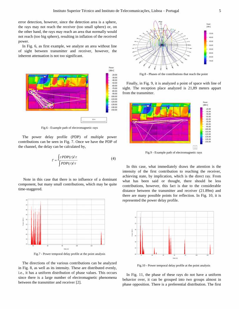
Typically, the bandwidth in Wi-Fi is in the order of 20
MHz. So the challenge is in detecting the Doppler Effect of a
few Hertz in 20MHz Wi-Fi signal bandwith. This problem is
solved by transforming the received signal into a narrow band
signal of a few Hertz as needed. Given this, the receiver
inspects the frequency of the pulses, as such, it can detect the
Doppler Effect of this order. The system uses OFDM based
systems. OFDM divides the available bandwidth into sub-
bands, carrying out modulation of each of these subchannels.
For example, the Wi-Fi divides the 20 MHz channel in 64 sub-
channels of 312.5 KHz. In this case, the receiver does not
perform the FFT operation on each OFDM symbol, but
performs a large number of FFT on M consecutive OFDM
symbols. As a result of this operation, the bandwidth of each
OFDM subchannel is reduced by factor M. In Fig. 12, it is
noted that the receiver performs the FFT operation on the 2N
points over two consecutive OFDM symbols,
2 22
2 2
1 1
i kn i knN N
N Nn k k
k k N
X x e x e
A (6)
A : Noise from the OFDM decoding process.
Fig.12 - Result of the FFT operation on one and two symbols respectively [1]
Returning to the above equation, since the first N symbols are
identical to the last N symbols, meaning that k k Nx x , with
1k until N, we can rewrite the equation,
2 2 ( )
2 2
1 1
i kn i k N nN N
N Nn k k
k k
X x e x e
A (7)
It is obtained,

Instituto Superior Técnico and Instituto de Telecomunicações, Lisboa – Portugal 7
2
2
1
1i knN
i nNn k
k
X x e e
A (8)
The above equation have two possible outcomes, i.e. when it is
an even number, and when it is an odd number. So we can
rewriting the equation:
2
2
1
2i klN
Nl k
k
X x e
, 2 1X 0l (9)
The first graph of Fig. 12 shows the result of the FFT on an
OFDM symbol. The second graph of the Fig. 12 shows the
result of the FFT operation on two identical OFDM symbols.
This occurs because the same information is sent in two
modulated OFDM information symbols. Thus, the bandwidth
of each subchannel passes to half of it. More generally, when a
receiver performs FFT on an OFDM symbol points repeatedly
M times, the bandwidth of each channel is M times reduced. In
conclusion, it is possible to create several narrow-band signals
centered at the center frequency of each subchannel by
repeating an OFDM symbol and performing a large number of
FFT operations.
In a house or building, typically, there are several people
influencing the electromagnetic propagation at the same time.
In order to solve the interference coming from the non-target
users, it is used MIMO capacity, this in order to focus the
gesture in a particular direction, and therefore in a particular
user [14, 17]. If we consider the various reflections from the
various humans as various emitters, it can, then, be separated
using a MIMO receiver. It is important at this point to note
that the decoder estimates the MIMO channel between the
transmitting antenna and the receiver by sending a known
preamble of each emitter. The target user needs to make a
repetitive gesture that become in a personal preamble and as a
result. The receiver can take this preamble to estimate the
MIMO channel that maximizes the energy of the reflections
from that user. Once booked this channel, we can already do
normal gestures.
Until now, it was assumed that the transmitter is transmitting
continuously and the receiver uses the signal to calculate the
Doppler Effect. However, this simplification is not feasible.
Although the transmission remains possible in a not very dense
network, in a real scenario can significantly affect the
throughput of other devices [3]. This technology does the
following: linearly interpolates the received OFDM symbol to
fill the time intervals where transmission does not happen. The
interpolation is performed by subchannel, after the OFDM
symbols are transformed to the frequency domain. After the
interpolation, the receiver makes all OFDM symbols, both
original and interpolated, back to the time domain and forms a
continuous time trace synthesized [2].
A transmitter sends a cyclic prefix between every two
consecutive OFDM symbols so that there is no intersymbol
interference. The aforementioned prefix is generated by taking
the last k bits of each OFDM symbol, so that, this prefix can
be regarded as a discontinuity between OFDM symbols. As
with this sampling of symbols is not supposed to change the
default Doppler Effect, so in practice the prefix is not
processed, reducing also the computational complexity.
Now, it is explained in three steps how to extract the
Doppler Effect and hence it makes the correspondence with
human gestures. Firstly, there is the Doppler extraction, which
processes the Doppler effect coming from the narrowband
signals; secondly there is the segmentation, which identifies a
set of segments that identifies the gesture and finally there is
the classification that determines the most likely gesture from
the set of defined gestures.
Doppler Effect extraction
The receiver extracts information about the Doppler
Effect processing a time-frequency profile of a
narrowband signal. To this end, the receiver
calculates an FFT sequence over time, i.e., calculates
the FFT on the samples in the first half second. FFT
can have such a resolution of 2 Hz. The receiver then
moves 5ms (prefix) and calculates the FFT during
another half second. Repeat the process until the
time-frequency profile is completed.
Fig.13 - Time-frequency profile of a gesture [1]
The Fig. 13 shows the time-frequency profile,
expressed in dB, from a user moving the hand
towards the receiver. The profile portrays that the
energy is concentrated around the DC frequency,
which corresponds to the signal energy between the
transmitter and the receiver without human
intervention. However, when the user starts the
movement is observed an increase of the positive
Doppler shift (corresponding to the hand’s
acceleration), and then a lower positive Doppler shift
(corresponding to the hand’s deceleration).
Segmentation
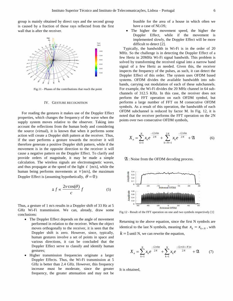
To accomplish this step, the receiver inspects
the Doppler profiles from the gestures defined in
Fig. 14, shown in Fig. 15. The last figure
mentioned shows that the profiles are a combination
of positive and negative Doppler Effect. Thus, each
listed profile contains a set of segments having
positive or negative Doppler Effect. For example, the
profile (a) has only one segment with a positive
Doppler Effect, however, the profile (e) is constituted
by two segments, one is a positive Doppler Effect and
the other is a negative Doppler Effect. The receiver
inspects the mentioned properties of the profile and
then clusters the segments to be able to see a pattern
that is probably the gesture.
Instituto Superior Técnico and Instituto de Telecomunicações, Lisboa – Portugal 8
Fig.14 - Tabulated gestures used in recognition over the
electromagnetic waves
Fig. 15 - Standard Doppler effect of each previously tabulated
gesture [1]
Classification
As already mentioned, the Doppler profile is
considered as a set of segments. As it can be seen in
Fig. 15, the Doppler profile is unique for each gesture
defined. So, the receiver can sort the gesture-based
segments of positive or negative Doppler Effect.
There are three segments: segments with Doppler
Effect only positive, segments with Doppler Effect
only negative and segments with positive and
negative Doppler Effect - mixed. It can represent
these effects to "1", "-1", "2", respectively. Every
gesture set can now be represented by a unique
sequence of three numbers. Given this, the
classification of the gesture may be made by
comparing the sequence obtained with a set of
already determined and unique sequence of each
gesture.
The described, so far, assumes that the target user performs
a gesture from a fixed location and performs a repetitive
motion (preamble) when changing position on the
environment. However, one can eliminate the need to repeat
the pattern mentioned when the user moves in space. In a more
concrete way, some human movements such as walking or
running, create a very significant Doppler Effect. It is greater
than the defined movements. So in principle the receiver can
track the MIMO channel as the subject user moves, without
thereby any need to repeat the gesture new preamble, because
it ignore the Doppler Effect bigger that the defined. It creates a
maximum and a minimum Doppler energy, ignoring what is
outside the range.
One of the hazards of this technology is a stranger to the
home user may have control over the receiver and
consequently of the house. To address this issue, there may be
a secret Doppler profile, so that only after this we can use
technology normally.
The extraction of Doppler profiles in the presence of signals
from multipath is quite challenging. However using only
positive and negative Doppler Effect in gestures classification
greatly simplifies the problem. There are two issues to be
resolved in this section. First, due to multipath, the target user,
gesturing toward the receiver in a certain room, can create
positive or negative Doppler Effect in the receiver. Secondly,
reflective materials such as metallic surfaces, for example, can
produce both positive and negative Doppler effects.
Exemplifying the situation, the receiver may see a negative
Doppler Effect if the target user move your hand towards the
receiver if it is near a metal surface behind the user [2]. To
solve the problem of obtaining the positive or negative
Doppler Effect, the receiver inspects the preamble. More
specifically, since, before completion of the gesture required to
move the hand towards the receiver, creating repetitive
preamble, a receiver can perform calibration and get the
correct Doppler Effect. For example, if the receiver note a
negative Doppler Effect where it should be positive (known
preamble), then the gesture recognition receiver inverts the
sign of the Doppler Effect. In conclusion, it is possible to
recognize the gesture, regardless of user location.
V. CONCLUSION
This paper addresses the use of the existing wireless
technologies, such as Wi-Fi, to build a system that recognizes
human gestures. Since the wireless signals need not line of
sight and can pass through walls, this system allows the
recognition of gestures in a certain indoor area with the use of
a few devices.
REFERENCES
[1] Q. Pu, S. Gupta, S. Gollakota, and S. Patel, “Whole-home gesture
recognition using wireless signals,” MobiCom’13, September 30–
October 4, Miami, FL, USA, 2013;
[2] J. M. Garcia; Topa, A., "Gesture Recognition by Electromagnetic-Wave
Reflection", Proc Encuentro Ibérico de Electromagnetismo
Computacional - EIEC , Baeza, Spain, Vol. 1, pp. 1 - 2, May, 2015;
[3] John C. Stein, “Indoor Radio WLAN Performance Part II: Range
Performance in a Dense Office Environment”, Intersil Corporation,
2401 Palm Bay, Florida 32905;
[4] Kamol Kaemarungsi, Prashant Krishnamurthy, “Properties of Indoor

Instituto Superior Técnico and Instituto de Telecomunicações, Lisboa – Portugal 9
Received Signal Strength for WLAN Location Fingerprinting”,
Proceedings of the First Annual International Conference on Mobile and
Ubiquitous Systems: Networking and Services (MobiQuitous’04),0-
7695-2208-4/04,2004,IEEE;
[5] Jean-Paul M. G. Linmartz's, Wireless Communication, The Interactive
Multimedia CD-ROM, Baltzer Science Publishers, P.O.Box 37208,
1030 AE Amsterdam, ISSN 1383 4231, Vol. 1 (1996), No.1;
[6] Dongjin Son, Bhaskar Krishnamachari, John Heidemann,
“Experimental study of the effects of Transmission Power Control and
Blacklisting in Wireless Sensor Networks”, Department of Electrical
Engineering-Systems, Information Sciences Institute Viterbi School of
Engineering, University of Southern California, Los Angeles, CA ;
[7] Anton A. Huurdeman, “The worldwide history of telecommunications”,
John Wiley & Sons, ISBN 0-471-20505-2;
[8] José Cavalheiro, "Telecomunicações e Redes”, Universidade Atlântica;
[9] Probability Distributions Relevants to Radiowave Propagation
Modelling, Recomendations ITU-R_P.1057;
[10] B.LeFloch, M. Alard, and C.Berrou, "Coded orthogonal frequency
division multiplex,", Proc. IEEE, vol.83, pp.982-1966, June 1995;
[11] Faculdade de Ciências e Tecnologia da Universidade de Lisboa,
Telecomunicações 1, 2004/2005, DEE;
[12] Daniel W. Bliss, Keith W. Forsythe, and Amanda M. Chan, “MIMO
Wireless Communications”, VOLUME 15, NUMBER 1, 2005,
LINCOLN LABORATORY JOURNAL;
[13] Dr. Jacob Sharony, “Introduction to Wireless MIMO, Theory and Applications”, IEEE LI, November 15, 2006;
[14] M. Fisher. Sweet Moves: Gestures and Motion-Based Controls on the
Galaxy S III;
[15] S. Gupta, D. Morris, S. Patel, and D. Tan. Soundwave: using the
doppler effect to sense gestures. In HCI 2012;
[16] Y. Kim and H. Ling. Human Activity Classification Based on Micro-
Doppler Signatures Using a Support Vector Machine. In Trans.
Geoscience and Remote Sensing, 2012;
[17] T. Ralston, G. Charvat, and J. Peabody. Real-time through-wall imaging
using an ultrawideband MIMO phased array radar system. In Array,
2010;
[18] S. Gollakota, F. Adib, D. Katabi, and S. Seshan. Clearing the RF Smog:
Making 802.11 Robu;
[19] K. Tan, J. Fang, Y. Zhang, S. Chen, L. Shi, J. Zhang, and Y. Zhang.
Fine-grained Channel Access in Wireles LAN. In SIGCOMM, 2010;
[20] Mathew G. Pelletier, “Multipath Interference Investigation for Cotton
Bale Microwave Moisture Sensing”, The Journal of Cotton Science
8:170–178 (2004);
[21] Joseph B. Keller, “Geometrical Theory of Diffraction”, Journal of the
Optical Society of America, Vol. 52, Issue 2, pp. 116-130,
1962, DOI: 10.1364/JOSA.52.000116;
[22] Y. Kim and H. Ling, “Human activity classification based on micro-
Doppler signatures using a support vector machine,” IEEE Trans.
Geoscience and Remote Sensing, 47 (5), 1328-1337, 2009.