GEOTECHNICAL REPORT ADDENDUM #1 - 4cd.edu REFERENCES.pdfHand Auger 4 in. Boring terminated at 1.5...
61
Carson (310) 684-4854 Rancho Cucamonga (909) 989-1751 Sacramento (916) 631-7194 San Diego (858) 609.7138 San Jose (408) 362-4920 October 19, 2017 Project Number: 16-0772-0 Contra Costa Community College Districtd 500 Court Street Martinez, CA 94553 Attention: Mr. Ray Pyle Subject: GEOTECHNICAL REPORT ADDENDUM #1 Switchgear Facility (D-4009) Diablo Valley College 321 Golf Club Road Pleasant Hill, California Reference: 1. Geotechnical Investigation Report for Proposed Switchgear Facility (D-4009), Diablo Valley College, prepared by RMA Group, Inc., project number 16-772-0, dated January 6, 2017. Dear Mr. Pyle: In accordance with your request, we have prepared the following geotechnical report addendum to address a proposed change in the location of the Switchgear enclosure facility. Based on our review of the revised site plan provided by YEI Engineers, we understand that the planned location of the proposed Switchgear Facility will be relocated approximately 90 feet to southwest. The proposed new location of the facility will place it immediately adjacent to the existing Engineering Technology Building (see attached Figure 1). In order to verify that the subsurface conditions of the relocated Switchgear facility are consistent with the conditions found during our previous investigation (Reference 1), a total of two hand auger borings were advanced within the footprint of the proposed new switchgear facility. Our borings encountered approximately 8 inches of top soil consisting of soft dark brown sandy lean clay with organics. Below the topsoil layer, our borings encountered very dense sandstone bedrock, known as Briones Sandstone, consisting of yellowish brown fine to medium silty sand as excavated. The presence of shallow bedrock was found to be consistent with bedrock found during our initial field investigation. Logs of our hand auger borings are presented as Figures 2 and 3 and attached to this addendum. Based on the findings of our additional field investigation, it is our professional opinion that the findings, conclusions, and recommendations of the referenced geotechnical report are considered to be applicable to the design and construction of the revised location of the switchgear facility. We trust that the information provided herewith will satisfy your present needs. Should you require additional information or have any questions, please contact our office. Sincerely, RMA Group Josh R. Summers, PE Gary Wallace, PG | CEG Engineering Manager Vice President - Geology PE 85240 CEG 1255 Jorge Meneses, PE, GE, PhD, D.GE, F. ASCE Principal Geotechnical Engineer GE 3041
Transcript of GEOTECHNICAL REPORT ADDENDUM #1 - 4cd.edu REFERENCES.pdfHand Auger 4 in. Boring terminated at 1.5...

Carson (310) 684-4854 Rancho Cucamonga (909) 989-1751 Sacramento (916) 631-7194
San Diego (858) 609.7138 San Jose (408) 362-4920
October 19, 2017 Project Number: 16-0772-0
Contra Costa Community College Districtd 500 Court Street Martinez, CA 94553
Attention: Mr. Ray Pyle
Subject: GEOTECHNICAL REPORT ADDENDUM #1 Switchgear Facility (D-4009) Diablo Valley College 321 Golf Club Road Pleasant Hill, California
Reference: 1. Geotechnical Investigation Report for Proposed Switchgear Facility (D-4009), Diablo Valley College,prepared by RMA Group, Inc., project number 16-772-0, dated January 6, 2017.
Dear Mr. Pyle:
In accordance with your request, we have prepared the following geotechnical report addendum to address a proposed change in the location of the Switchgear enclosure facility.
Based on our review of the revised site plan provided by YEI Engineers, we understand that the planned location of the proposed Switchgear Facility will be relocated approximately 90 feet to southwest. The proposed new location of the facility will place it immediately adjacent to the existing Engineering Technology Building (see attached Figure 1).
In order to verify that the subsurface conditions of the relocated Switchgear facility are consistent with the conditions found during our previous investigation (Reference 1), a total of two hand auger borings were advanced within the footprint of the proposed new switchgear facility. Our borings encountered approximately 8 inches of top soil consisting of soft dark brown sandy lean clay with organics. Below the topsoil layer, our borings encountered very dense sandstone bedrock, known as Briones Sandstone, consisting of yellowish brown fine to medium silty sand as excavated. The presence of shallow bedrock was found to be consistent with bedrock found during our initial field investigation. Logs of our hand auger borings are presented as Figures 2 and 3 and attached to this addendum.
Based on the findings of our additional field investigation, it is our professional opinion that the findings, conclusions, and recommendations of the referenced geotechnical report are considered to be applicable to the design and construction of the revised location of the switchgear facility.
We trust that the information provided herewith will satisfy your present needs. Should you require additional information or have any questions, please contact our office.
Sincerely,
RMA Group
Josh R. Summers, PE Gary Wallace, PG | CEG Engineering Manager Vice President - Geology PE 85240 CEG 1255
Jorge Meneses, PE, GE, PhD, D.GE, F. ASCE Principal Geotechnical Engineer GE 3041

Switchgear Facility (D-4009)Diablo Valley College | Contra Costa Community College District
RMA Project No.: 16-772-0Figure 1
Previous Location of Proposed Switchgear Enclosure
Revised Location of Proposed Switchgear Enclosure
SITE GEOLOGIC MAPScale: 1 inch ≈ 30 feet
Tbraf/Tbr
B-3-1
B-3-2
B-3-3
B-3-4
Contact
Geologic Legend
Approx. Boring LocationB-3-1
Briones SandstoneTbr
Artificial Fillaf
Approx. Hand Auger Boring Location
B-3-3
Base Map: Google Earth Aerial Image Dated 3/11/2017

Material DescriptionSamples
Dep
th(f
t)
Sam
ple
Typ
e
Blo
ws
(blo
ws/
ft)
Bu
lkSa
mp
le
Mo
istu
reC
on
ten
t(%
)
Dry
Den
sity
(pcf
)
USC
S This log contains factual information and interpretation of the subsurface conditions between the samples. The stratum indicated on this log represent the approximate boundary between earth units and the transition may be gradual. The log show subsurface conditions at the date and location indicated, and may not be representative of subsurface conditions at other locations and times.
Gra
ph
icSy
mb
ol
1
2
3
5
6
7
4
Date Drilled:
Logged By:
Location:
Drilling Equipment:
Borehole Diameter:
Drive Weights:
Exploratory Boring Log
D. Hassel
Not ApplicableSee Site Geologic Map
Boring No.Sheet of
Drop Height: Not Applicable
- Groundwater
- End of Boring
S
T
- SPT Sample
- Modified California Tube Sample
- Bulk Sample
Sample Types: Symbols:*NoteAll blow counts associated with Modified California Sample are uncorrected. The sampler dimensions are as follows:
ID = 2.5" OD = 3"R - Ring Sample
RMA Project No.: 16-0772-0Figure 2
Switchgear Facility (D-4009)Diablo Valley College | Contra Costa Community College District
Elevation:
October 6, 2017
B-3-31 1
Hand Auger
4 in.
Boring terminated at 2.0 feetNo groundwater encounteredHole backfilled with soil cuttings
62 feet (approx.)
Briones Sandstone (Tbr): Yellow brown silty sandstone, fine to medium sand, about 15% silt, moist, very dense
--
CL Top Soil: Dark brown sandy lean clay, fine to medium sand, medium plasticity, moist, organics consisting of grass roots, soft

Material DescriptionSamples
Dep
th(f
t)
Sam
ple
Typ
e
Blo
ws
(blo
ws/
ft)
Bu
lkSa
mp
le
Mo
istu
reC
on
ten
t(%
)
Dry
Den
sity
(pcf
)
USC
S This log contains factual information and interpretation of the subsurface conditions between the samples. The stratum indicated on this log represent the approximate boundary between earth units and the transition may be gradual. The log show subsurface conditions at the date and location indicated, and may not be representative of subsurface conditions at other locations and times.
Gra
ph
icSy
mb
ol
1
2
3
5
6
7
4
Date Drilled:
Logged By:
Location:
Drilling Equipment:
Borehole Diameter:
Drive Weights:
Exploratory Boring Log
D. Hassel
Not ApplicableSee Site Geologic Map
Boring No.Sheet of
Drop Height: Not Applicable
- Groundwater
- End of Boring
S
T
- SPT Sample
- Modified California Tube Sample
- Bulk Sample
Sample Types: Symbols:*NoteAll blow counts associated with Modified California Sample are uncorrected. The sampler dimensions are as follows:
ID = 2.5" OD = 3"R - Ring Sample
RMA Project No.: 16-0772-0Figure 3
Switchgear Facility (D-4009)Diablo Valley College | Contra Costa Community College District
Elevation:
October 6, 2017
B-3-41 1
Hand Auger
4 in.
Boring terminated at 1.5 feetNo groundwater encounteredHole backfilled with soil cuttings
62 feet (approx.)
Briones Sandstone (Tbr): Yellow brown silty sandstone, fine to medium sand, about 15% silt, moist, very dense
--
CL Top Soil: Dark brown sandy lean clay, fine to medium sand, medium plasticity, moist, organics consisting of grass roots, soft

January 25, 2017 16-772-P
GEOTECHNICAL INVESTIGATION REPORT forPROPOSED SWITCHGEAR FACILITY (D4009)DIABLO VALLEY COMMUNITY COLLEGEPLEASANT HILL, CA
FOR:CONTRA COSTA COMMUNITY COLLEGE DISTRICT500 COURT STREETMARTINEZ, CA 94553
3150 Fitzgerald Road, Rancho Cordova, CA 95742 | T: 916.631.7194 | F: 916.631.7256 | www.rmacompanies.com
January 25, 2017 RMA Project No.: 16-772-0
Contra Costa Community College District 500 Court Street Martinez, CA 94553
Attention: Mr. Ray Pyle
Subject: Geotechnical Investigation for Proposed Electrical Switchgear Facility (D-4009) Diablo Valley College 321 Golf Club Road Pleasant Hill, CA
Dear Mr. Pyle:
In accordance with your request, a geotechnical investigation has been completed for the above-referenced project. The report addresses both engineering geologic and geotechnical conditions. The results of the investigation are presented in the accompanying report, which includes a description of site conditions, results of our field exploration and laboratory testing, conclusions, and recommendations.
We appreciate this opportunity to be of continued service to you. If you have any questions regarding this report, please do not hesitate to contact us at your convenience.
Respectfully submitted,
RMA Group
Josh Summers, PE Project Engineer PE 85240
Gary Wallace, PG|CEG Vice President - Geology CEG 1255
Jorge Meneses, PE|GE|PhD|D.GE|F. ASCE Principal Geotechnical Engineer GE 3041

GEOTECHNICAL INVESTIGATION FOR
PROPOSED SWITCHGEAR FACILITY (D-4009) DIABLO VALLEY COLLEGE
321 GOLF CLUB ROAD PLEASANT HILL, CA
for
Contra Costa Community College District 500 Court Street
Martinez, CA 94553
January 25, 2017
16-772-0
Electrical Switchgear Facility (D-4009) January 25, 2017 Diablo Valley College | Contra Costa Community College District RMA Job No.: 16-772-0 Page i
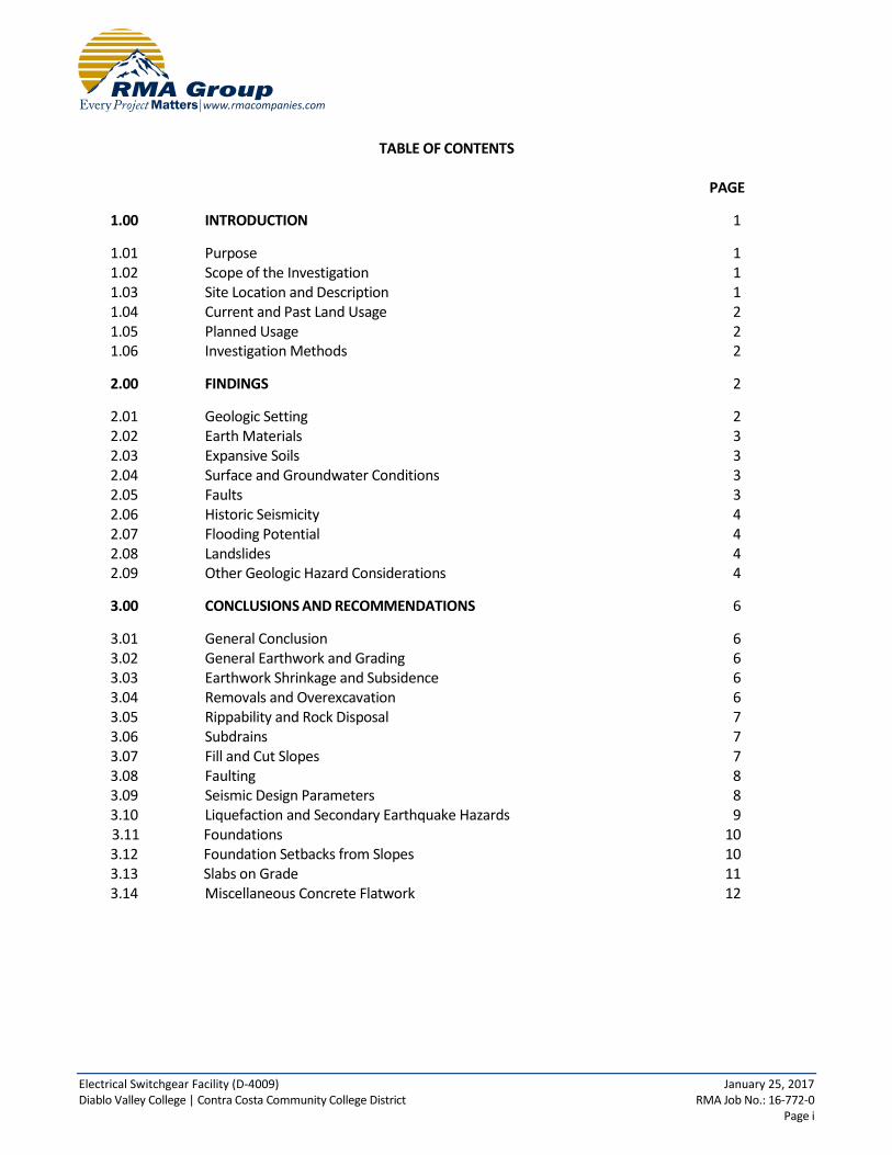
TABLE OF CONTENTS PAGE
1.00 INTRODUCTION 1
1.01 Purpose 1 1.02 Scope of the Investigation 1 1.03 Site Location and Description 1 1.04 Current and Past Land Usage 2 1.05 Planned Usage 2 1.06 Investigation Methods 2
2.00 FINDINGS 2
2.01 Geologic Setting 2 2.02 Earth Materials 3 2.03 Expansive Soils 3 2.04 Surface and Groundwater Conditions 3 2.05 Faults 3 2.06 Historic Seismicity 4 2.07 Flooding Potential 4 2.08 Landslides 4 2.09 Other Geologic Hazard Considerations 4
3.00 CONCLUSIONS AND RECOMMENDATIONS 6
3.01 General Conclusion 6 3.02 General Earthwork and Grading 6 3.03 Earthwork Shrinkage and Subsidence 6 3.04 Removals and Overexcavation 6 3.05 Rippability and Rock Disposal 7 3.06 Subdrains 7 3.07 Fill and Cut Slopes 7 3.08 Faulting 8 3.09 Seismic Design Parameters 8 3.10 Liquefaction and Secondary Earthquake Hazards 9 3.11 Foundations 10 3.12 Foundation Setbacks from Slopes 10 3.13 Slabs on Grade 11 3.14 Miscellaneous Concrete Flatwork 12

Electrical Switchgear Facility (D-4009) January 25, 2017 Diablo Valley College | Contra Costa Community College District RMA Job No.: 16-772-0 Page ii
TABLE OF CONTENTS (Continued)
PAGE 3.15 Footing Excavation and Slab Preparations 12 3.16 Lateral Load Resistance 13 3.17 Drainage and Moisture Proofing 13 3.18 Cement Type and Corrosion Potential 14 3.19 Temporary Slopes 14 3.20 Utility Trench Backfill 16 3.21 Pavement Sections 16 3.22 Plan Review 17 3.23 Geotechnical Observation and Testing During Rough Grading 17 3.24 Post-Grading Geotechnical Observation and Testing 17 4.00 CLOSURE 18 FIGURES AND TABLES Figure 1 Site Location Map Figure 2 Regional Geologic Map Figure 3 Site Geologic Map Figure 4 Geologic Cross Section Figure 5 Regional Fault Map Table 1 Notable Faults within 100 Km Table 2 Historical Strong Earthquakes APPENDICES Appendix A Field Investigation A1 Appendix B Laboratory Tests B1 Appendix C General Earthwork and Grading Specifications C1 Appendix D References D1

Electrical Switchgear Facility (D-4009) January 25, 2017 Diablo Valley College | Contra Costa Community College District RMA Job No.: 16-772-0 Page 1
1.00 INTRODUCTION
1.01 Purpose
A geotechnical investigation has been completed for a new electrical switchgear facility at Diablo Valley College in Pleasant Hill, California. The purpose of the investigation was to summarize geotechnical and geologic conditions at the site, to assess their potential impact on the proposed development, and to develop geotechnical and engineering geologic design parameters.
1.02 Scope of the Investigation
The general scope of this investigation included the following:
Review of published and unpublished geologic, seismic, groundwater and geotechnical literature.
Examination of aerial photographs.
Contacting of underground service alert to locate onsite utility lines.
Locating of underground utilities using a private utility locator.
Contacting the Contra Costa County Environmental Health Department and obtaining well permits for the drilling of exploratory borings.
Logging, sampling and backfilling of 2 exploratory borings drilled with a CME-45B drill rig.
Laboratory testing of representative soil samples.
Geotechnical evaluation of the compiled data.
Preparation of this report presenting our findings, conclusions and recommendations.
Our scope of work did not include a preliminary site assessment for the potential of hazardous materials onsite.
1.03 Site Location and Description
The proposed switchgear facility will be located within the existing Diablo Valley College campus in the City of Pleasant Hill, Contra Costa County, California. The address of the school is 321 Golf Club Road.
The school is bounded by Viking Drive to the south, residential development and the Contra Costa Canal to the west, Golf Club Road to the north, and Grayson Creek to the east (Figure 1). Its geographic position is at Latitude 37.96831° and Longitude -122.07004°.
The overall gradient of the property is about 30% to the west. Elevation at the site is approximately 62 feet above mean sea level.
The proposed switchgear facility at Diablo Valley College is situated within the existing college campus and is currently covered with maintained landscaping, asphalt pavement, and concrete walkways. The proposed facility site is located on the slope between parking lot 3 and the Engineering Technology complex, immediately south of an existing utility shed.

Electrical Switchgear Facility (D-4009) January 25, 2017 Diablo Valley College | Contra Costa Community College District RMA Job No.: 16-772-0 Page 2
1.04 Current and Past Land Usage
Aerial photographs indicate that the proposed construction site was vacant from at least 1946 to 1949. Diablo Valley College officially opened in 1952. Aerial photographs reviewed from 1958 to 1968 show that significant construction occurred within the limits of the campus. Aerial photographs reviewed from 1980 to 2012 show that conditions within the proposed construction site during that time period were similar to conditions that currently exist at the site.
1.05 Planned Usage
It is our understanding that the proposed construction will consist of a single-story building covering approximately 450 square feet to house electrical equipment. In addition, the proposed construction will also include a retaining wall located immediately west of the proposed structure.
Our investigation was performed prior to the preparation of grading or foundation plans. To aid in preparation of this report, we utilized the following assumptions:
Maximum foundation loads of 2 to 3 kips per linear foot for continuous footings and 60 kips for isolated spread footings.
Cuts and fills will be less than 5 feet.
1.06 Investigation Methods
Our investigation consisted of office research, field exploration, laboratory testing, review of the compiled data, and preparation of this report. It has been performed in a manner consistent with generally accepted engineering and geologic principles and practices, and has incorporated requirements of California Geological Survey Note 48 and the California Buildings Code (CBC). Definitions of technical terms and symbols used in this report include those of the ASTM International, the California Building Code, and commonly used geologic nomenclature. Technical supporting data are presented in the attached appendices. Appendix A presents a description of the methods and equipment used in performing the field exploration and logs of our subsurface exploration. Appendix B presents a description of our laboratory testing and the test results. Appendix C presents the results of site-specific seismic hazard analysis including the development of design acceleration response spectra for this project. Standard grading specifications and references are presented in Appendices C and D, respectively.
2.00 FINDINGS
2.01 Geologic Setting
The Diablo Valley College is located within the central Coast Ranges geomorphic province. This province consists of northwest trending mountain ranges and valleys that extend from southern California to Oregon. The bedrock within the Coast Ranges consists of a belt of sedimentary, volcanic and metamorphic rocks that have been deformed by transpressional stresses concentrated along the San Andreas fault zone. Valleys within the Coast Ranges are filled with Holocene age alluvium and older sedimentary deposits.
The proposed Switchgear facility is located in the eastern fringe of the Berkeley Hills just west of the Ygnacio Valley Groundwater Basin (California Department of Water Resources, 2004). According to regional geologic mapping by Dibblee and Minch (2005), the Switchgear site is underlain by the Tertiary age Briones Sandstone which has been

Electrical Switchgear Facility (D-4009) January 25, 2017 Diablo Valley College | Contra Costa Community College District RMA Job No.: 16-772-0 Page 3
locally folded into a syncline with steeply dipping limbs (Figure 2).
2.02 Earth Materials
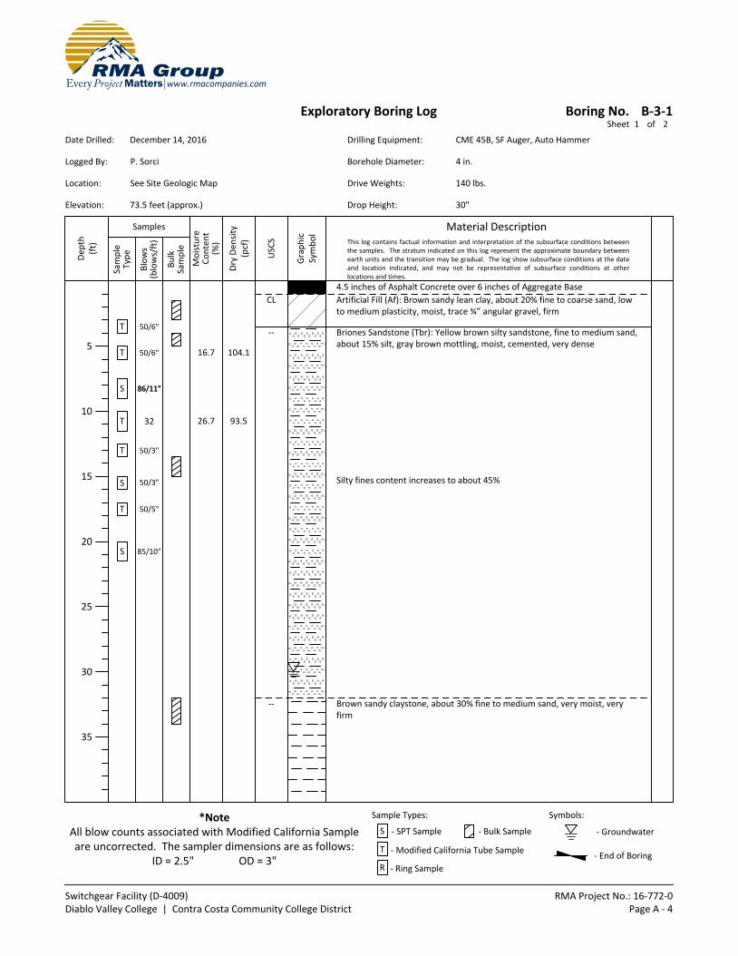
Our subsurface investigation encountered asphalt, base, artificial fill and sedimentary bedrock.
The asphalt was found to be 4.5 inches thick in Boring B-3-1 and 4 inches thick in Boring B-3-2. Six inches of aggregate base was encountered beneath the asphalt in both borings.
Approximately 3.5 feet of artificial fill composed of sandy lean clay was found to underlie the base in Boring B-3-1.
Sandstone bedrock, the Briones Sandstone, was found to underlie the fill in Boring B-3-1 and the base in Boring B-3-2. It was observed to be yellowish brown in color with some reddish brown and gray brown mottling, fine to medium grained, very dense and hard. Blow counts using a 140 lbs hammer and 30 inch drop ranged from 32 to 50 for 3 inches for a California split spoon sampler and 50 for 3 inches to 86 for 11 inches for a standard penetration test sampler. The sandstone was observed to be essential massive with some subtle, high angle variations in grained sizes possibly suggestive of bedding. The sandstone was found to be underlain by brown claystone at a depth of 32 feet in Boring B-3-1 and light brown siltstone at a depth of 8.5 feet in Boring B-3-2. The siltstone or a harder underlying layer caused refusal to drilling at a depth of 10 feet in Boring B-3-2. Orientation of the contact between the sandstone and the underlying siltstone/claystone could not be determined by the drilling method used.
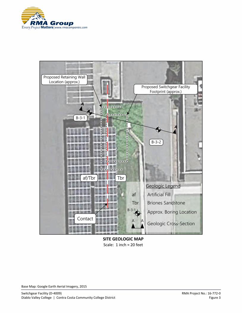
A Site Geologic Map showing the locations of our borings is presented as Figure 3. A geologic cross section is presented as Figure 4.
The subsurface soils encountered in the exploratory borings drilled at the site are described in greater detail on the logs contained in Appendix A.
2.03 Expansive Soils
Soil classification and particle size analysis indicate that near surface soils have a very low expansion potential.
2.04 Surface and Groundwater Conditions
No areas of ponding or standing water were present at the time of our study. Further, no springs or areas of natural seepage were found.
Minor groundwater seepage within the Briones Sandstone was encountered in Boring B-3-1 at a depth of 30 feet. However, California Department of Water Resources (Bulletin 118, 2004) did not identify the Briones Sandstone as a water bearing formation.
2.05 Faults
The site is not located within the boundaries of an Earthquake Fault Zone for fault-rupture hazard as defined by the Alquist-Priolo Earthquake Fault Zoning Act and no faults are known to pass through the property. The nearest Earthquake Fault Zone is located about 1¾ mile to the northeast along the Concord fault.
Locally, Dibblee (2005) mapped a fault concealed by alluvium about ¼ of a mile to the east of the Switchgear site and bedrock faults about ½ of a mile and more to the north and northwest of the Switchgear site (Figure 2). These faults are not unknown to be active and have not been included in Alquist-Priolo Earthquake Fault Zones.
The accompanying Regional Fault Map (Figure 4) illustrates the location of the site with respect to major faults in the

Electrical Switchgear Facility (D-4009) January 25, 2017 Diablo Valley College | Contra Costa Community College District RMA Job No.: 16-772-0 Page 4
region. The distance to notable faults within 100 kilometers of the site is presented on Table 1.
2.06 Historic Seismicity
Numerous large earthquakes have occurred in the San Francisco region, but none have been epicentered near the site. The most notable earthquakes in the region were the great San Francisco Earthquake of 1906 and the Loma Prieta Earthquake of 1989. The Great San Francisco Earthquake had a magnitude of approximately 7.8 and was epicentered about 86 miles from the site. The Loma Prieta Earthquake had a magnitude of 6.9 and was epicentered about 80 miles from the site.
Strong earthquakes that have occurred in this region in historic time and their approximate epicentral distances are summarized in Table 2.
Seismic design parameters relative to the requirements of the 2016 California Building Code and ASCE 7 are presented in Section 3.09.
2.07 Flooding Potential
According to Federal Emergency Management Agency (2009), the site is located within Flood Zone X, which is an area determined to be outside the 0.2% annual chance floodplain.
Control of surface runoff originating from within and outside of the site should, of course, be included in design of the project.
2.08 Landslides
Landslides were not encountered during the current subsurface investigation and topographic landforms suggestive of landslides were not apparent in the field or on aerial photographs.
On a regional perspective, Dibblee and Minch (2005) do not map any landslides within the site (Figure 2).
2.09 Other Geologic Hazard Considerations
California Geological Survey Note 48 (2013) identifies a number of exceptional geologic hazards that can occur at individual sites, but do not occur statewide. Evaluation of these exceptional conditions is referred to as a conditional geologic assessment by Note 48. Specific assessment items listed in Note 48 are addressed in the table on the following page.

Electrical Switchgear Facility (D-4009) January 25, 2017 Diablo Valley College | Contra Costa Community College District RMA Job No.: 16-772-0 Page 5
CONDITIONAL GEOLOGIC ASSESSMENT
Hazard Assessment Reference
Methane gas, hydrogen-sulfide gas, tar seeps
Not applicable, site is not located within an oil field identified as a high risk area for hazardous gas accumulations.
See Section 2.02
Volcanic eruption Not applicable, site is not is a known hazard area for volcanic eruptions.
Miller, 1989
(U.S.G.S. Bulletin 1847)
Flooding The proposed development area is not located within the boundaries of a 100-year flood zone.
See Section 2.07
Tsunami and seiches inundation
Not applicable. See Section 3.10
Radon-222 gas Not applicable based on proposed use. See Section 1.04
Naturally occurring asbestos Not applicable, site is not underlain by serpentinite bedrock.
See Section 2.01
Hydrocollapse due to anthropic use of water
Not applicable, the site is underlain by bedrock.
See Section 2.01
Regional land subsidence Not applicable, the site is underlain by bedrock.
See Section 2.01
Clays and cyclic softening Not applicable, the site is underlain by bedrock.
See Section 3.04 and 3.12
Electrical Switchgear Facility (D-4009) January 25, 2017 Diablo Valley College | Contra Costa Community College District RMA Job No.: 16-772-0 Page 6
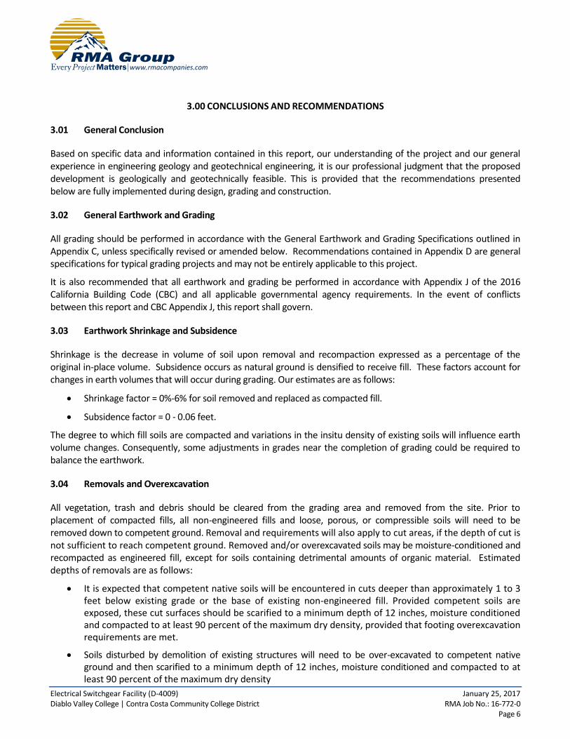
3.00 CONCLUSIONS AND RECOMMENDATIONS
3.01 General Conclusion
Based on specific data and information contained in this report, our understanding of the project and our general experience in engineering geology and geotechnical engineering, it is our professional judgment that the proposed development is geologically and geotechnically feasible. This is provided that the recommendations presented below are fully implemented during design, grading and construction.
3.02 General Earthwork and Grading
All grading should be performed in accordance with the General Earthwork and Grading Specifications outlined in Appendix C, unless specifically revised or amended below. Recommendations contained in Appendix D are general specifications for typical grading projects and may not be entirely applicable to this project.
It is also recommended that all earthwork and grading be performed in accordance with Appendix J of the 2016 California Building Code (CBC) and all applicable governmental agency requirements. In the event of conflicts between this report and CBC Appendix J, this report shall govern.
3.03 Earthwork Shrinkage and Subsidence
Shrinkage is the decrease in volume of soil upon removal and recompaction expressed as a percentage of the original in-place volume. Subsidence occurs as natural ground is densified to receive fill. These factors account for changes in earth volumes that will occur during grading. Our estimates are as follows:
Shrinkage factor = 0%-6% for soil removed and replaced as compacted fill.
Subsidence factor = 0 - 0.06 feet.
The degree to which fill soils are compacted and variations in the insitu density of existing soils will influence earth volume changes. Consequently, some adjustments in grades near the completion of grading could be required to balance the earthwork.
3.04 Removals and Overexcavation
All vegetation, trash and debris should be cleared from the grading area and removed from the site. Prior to placement of compacted fills, all non-engineered fills and loose, porous, or compressible soils will need to be removed down to competent ground. Removal and requirements will also apply to cut areas, if the depth of cut is not sufficient to reach competent ground. Removed and/or overexcavated soils may be moisture-conditioned and recompacted as engineered fill, except for soils containing detrimental amounts of organic material. Estimated depths of removals are as follows:
It is expected that competent native soils will be encountered in cuts deeper than approximately 1 to 3 feet below existing grade or the base of existing non-engineered fill. Provided competent soils are exposed, these cut surfaces should be scarified to a minimum depth of 12 inches, moisture conditioned and compacted to at least 90 percent of the maximum dry density, provided that footing overexcavation requirements are met.
Soils disturbed by demolition of existing structures will need to be over-excavated to competent native ground and then scarified to a minimum depth of 12 inches, moisture conditioned and compacted to at least 90 percent of the maximum dry density

Electrical Switchgear Facility (D-4009) January 25, 2017 Diablo Valley College | Contra Costa Community College District RMA Job No.: 16-772-0 Page 7
The asphalt and concrete currently onsite may be either processed and placed in the compacted fill, or hauled off the site. If the asphalt and concrete is use as fill material, it must be broken down to approximately 4 to 8-inch particles and mixed thoroughly with on-site soils. No large and flat pieces are to be used for fill. If asphalt is processed by grinding, it cannot be used in fills and must be removed from the site.
In addition to the above requirements, overexcavation will also need to meet the following criteria for the building pads, concrete flatwork and pavement areas:
Provided that the undisturbed bedrock is fully exposed at the foundation level, footing areas will not require overexcavation.
If bedrock is not exposed or if bedrock is only partially exposed at the foundation level, overexcavation should be performed as follows: (1) All footing areas, both continuous and spread, shall be undercut, moistened, and compacted as necessary to produce soils compacted to a minimum of 95% relative compaction to a depth equal to the width of the footing below the bottom of the footing or to a depth of 3 feet below the bottom of the footing, whichever is less. Footing areas shall be defined as the area extending from the edge of the footing for a distance of 5 feet. (2) Alternatively, footings may be deepened to provide a minimum of 12 inches of embedment into bedrock.
All floor slabs, concrete flatwork and paved areas shall be underlain by a minimum of 12 inches of soil compacted to a minimum of 90% relative compaction.
The exposed soils beneath all overexcavation should be scarified an additional 12 inches, moisture conditioned and compacted to a minimum of 90% relative compaction.
The above recommendations are based on the assumption that soils encountered during field exploration are representative of soils throughout the site. However, there can be unforeseen and unanticipated variations in soils between points of subsurface exploration. Hence, overexcavation depths must be verified, and adjusted if necessary, at the time of grading. The overexcavated materials may be moisture-conditioned and re-compacted as engineered fill.
3.05 Rippability and Rock Disposal
Our exploratory borings were advanced without difficulty and no oversize materials were encountered in our subsurface investigation. Accordingly we expect that all earth materials will be rippable with conventional heavy duty grading equipment and oversized materials are not expected.
It should be noted that some excavation difficulty may be encountered during construction when excavating into the bedrock encountered in our exploratory borings.
3.06 Subdrains
Surface water was not present at the time of our investigation. Minor Seepage was encountered in boring B-3-1 at a depth of about 30 feet below the ground surface. However, this is well below the anticipated depths of grading. Consequently, installation of subdrains is not expected to be necessary.
3.07 Fill and Cut Slopes
Fill and cut slopes reaching maximum heights feet of approximately 12 feet at inclinations of 2 to 1 (horizontal to vertical, H:V) or flatter are expected to be grossly and surficially stable. This is provided that fill slopes are properly keyed and compacted, as indicated in Appendix C, and cut slopes expose bedrock with favorable geologic structure
Electrical Switchgear Facility (D-4009) January 25, 2017 Diablo Valley College | Contra Costa Community College District RMA Job No.: 16-772-0 Page 8
and competent soils. Cut and fill slope stability should be further reviewed upon development of a grading plan.
3.08 Faulting
Since the site is not located within the boundaries of an Earthquake Fault Zone and no faults are known to pass through the property, surface fault rupture within the site is considered unlikely.
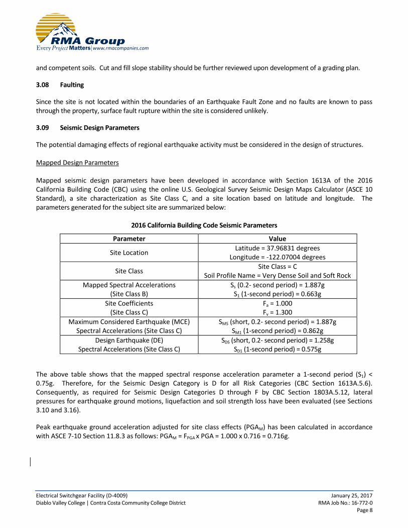
3.09 Seismic Design Parameters
The potential damaging effects of regional earthquake activity must be considered in the design of structures. Mapped Design Parameters Mapped seismic design parameters have been developed in accordance with Section 1613A of the 2016 California Building Code (CBC) using the online U.S. Geological Survey Seismic Design Maps Calculator (ASCE 10 Standard), a site characterization as Site Class C, and a site location based on latitude and longitude. The parameters generated for the subject site are summarized below:
2016 California Building Code Seismic Parameters
Parameter Value
Site Location Latitude = 37.96831 degrees
Longitude = -122.07004 degrees
Site Class Site Class = C
Soil Profile Name = Very Dense Soil and Soft Rock
Mapped Spectral Accelerations (Site Class B)
Ss (0.2- second period) = 1.887g S1 (1-second period) = 0.663g
Site Coefficients (Site Class C)
Fa = 1.000 Fv = 1.300
Maximum Considered Earthquake (MCE) Spectral Accelerations (Site Class C)
SMS (short, 0.2- second period) = 1.887g SM1 (1-second period) = 0.862g
Design Earthquake (DE) Spectral Accelerations (Site Class C)
SDS (short, 0.2- second period) = 1.258g SD1 (1-second period) = 0.575g
The above table shows that the mapped spectral response acceleration parameter a 1-second period (S1) < 0.75g. Therefore, for the Seismic Design Category is D for all Risk Categories (CBC Section 1613A.5.6). Consequently, as required for Seismic Design Categories D through F by CBC Section 1803A.5.12, lateral pressures for earthquake ground motions, liquefaction and soil strength loss have been evaluated (see Sections 3.10 and 3.16).
Peak earthquake ground acceleration adjusted for site class effects (PGAM) has been calculated in accordance with ASCE 7-10 Section 11.8.3 as follows: PGAM = FPGA x PGA = 1.000 x 0.716 = 0.716g.

Electrical Switchgear Facility (D-4009) January 25, 2017 Diablo Valley College | Contra Costa Community College District RMA Job No.: 16-772-0 Page 9
3.10 Liquefaction and Secondary Earthquake Hazards
Potential secondary seismic hazards that can affect land development projects include liquefaction, tsunamis, seiches, seismically induced settlement, seismically induced flooding and seismically induced landsliding.
Liquefaction
Liquefaction is a phenomenon where earthquake- induced ground vibrations increase the pore pressure in saturated, granular soils until it is equal to the confining, overburden pressure. When this occurs, the soil can completely lose its shear strength and enter a liquefied state. The possibility of liquefaction is dependent upon grain size, relative density, confining pressure, saturation of the soils, and intensity and duration of ground shaking. In order for liquefaction to occur, three criteria must be met: underlying loose, coarse-grained (sandy) soils, a groundwater depth of less than about 50 feet, and a potential for seismic shaking from nearby large-magnitude earthquake. Because the site is underlain by bedrock, the potential for liquefaction is nil. It should be noted that the California Geological Survey has not yet prepared a Seismic Hazard Zone Map of potential liquefaction hazards for the quadrangle in which the site is located.
Tsunamis and Seiches
Tsunamis are sea waves that are generated in response to large-magnitude earthquakes. When these waves reach shorelines, they sometimes produce coastal flooding. Seiches are the oscillation of large bodies of standing water, such as lakes, that can occur in response to ground shaking. Tsunamis and seiches do not pose hazards due to the inland location of the site and lack of nearby bodies of standing water.
Seismically Induced Settlement
Seismically induced settlement occurs most frequently in areas underlain by loose, granular sediments. Damage as a result of seismically induced settlement is most dramatic when differential settlement occurs in areas with large variations in the thickness of underlying sediments. Settlement caused by ground shaking is often non-uniformly distributed, which can result in differential settlement. Because the site is underlain by bedrock, no significant seismically induced settlement is expected to occur at the site.
Seismically Induced Flooding
There are no up gradient water reservoirs or dams located in close proximity of the site. Consequently seismically induced flooding at the site is unlikely.
Seismically Induced Landsliding
Since the bedrock within the site consists of dense, essentially massive sandstone, seismically induced landsliding is unlikely to occur at the site. It should be noted that the California Geological Survey has not yet prepared a Seismic Hazard Zone Map of potential earthquake-induced landslide hazards for the quadrangle in which the site is located.

Electrical Switchgear Facility (D-4009) January 25, 2017 Diablo Valley College | Contra Costa Community College District RMA Job No.: 16-772-0 Page 10
3.11 Foundations
Isolated spread footings and/or continuous wall footings are recommended to support the proposed structures. If the recommendations in the section on grading are followed and footings are established in firm native soils or compacted fill materials, footings may be designed using the following allowable soil bearing values:
Continuous Wall Footings:
Footings having a minimum width of 12 inches and a minimum depth of 12 inches below the lowest adjacent grade have allowable bearing capacity of 3,250 pounds per square foot (psf). This value may be increased by 10% for each additional foot of width and/or depth to a maximum value of 5,250 psf.
Isolated Spread Footings:
Footings having a minimum width of 12 inches and a minimum depth of 12 inches below the lowest adjacent grade have allowable bearing capacity of 3,500 psf. This value may be increased by 10% for each additional foot of width or depth to a maximum value of 5,250 psf.
Retaining Wall Footings:
Footings for retaining walls should be founded a minimum depth of 12 inches and have a minimum width of 12 inches. Footings may be designed using the allowable bearing capacity and lateral resistance values recommended for building footings. However, when calculating passive resistance, the upper 6 inches of the footings should be ignored in areas where the footings will not be covered with concrete flatwork. This value may also be increased by 10% for each additional foot of width or depth to a maximum value of 5,250 psf. Reinforcement should be provided for structural considerations as determined by the design engineer.
The above bearing capacities represent an allowable net increase in soil pressure over existing soil pressure and may be increased by one-third for short-term wind or seismic loads. The maximum expected settlement of footings designed with the recommended allowable bearing capacity is expected to be on the order of ½ inch with differential settlement on the order of ¼ inch.
Soils at the site are generally granular, non-plastic and non-expansive in nature. Therefore, reinforcement of footings for expansive soil is not required. However, in view of the seismic setting, a nominal reinforcement consisting of one #4 bar placed within 3 inches of the top of footings and another placed within 3 inches of the bottom of footings is recommended. The structural engineer may require heavier reinforcement.
Due to the preliminary nature of the expansion tests performed for this study, we recommend additional testing be performed near the completion of rough grading to verify the test results and recommended foundation design criteria.
3.12 Foundation Setbacks from Slopes
Setbacks for footings adjacent to slopes should conform to the requirements of the California Building Code (CBC). Specifically, footings should maintain a horizontal distance or setback between any adjacent slope face and the bottom outer edge of the footing.
For slopes descending away from the foundation, the horizontal distance may be calculated by using h/3, where h is the height of the slope. The horizontal setback should not be less than 5 feet, nor need not be greater than 40 feet (per CBC). Where structures encroach within the zone of h/3 from the top of the slope the setback may be maintained by deepening the foundations. Flatwork and utilities within the zone of h/3 from the top of slope may be subject to lateral distortion caused by gradual downslope creep. Walls, fences and landscaping improvements

Electrical Switchgear Facility (D-4009) January 25, 2017 Diablo Valley College | Contra Costa Community College District RMA Job No.: 16-772-0 Page 11
constructed at the top of descending slopes should be designed with consideration of the potential for gradual downslope creep.
For ascending slopes, the horizontal setback required may be calculated by using h/2 where h is the height of the slope. The horizontal setback need not be greater than 15 feet (per CBC).
3.13 Slabs on Grade
We recommend the use of unreinforced slabs on grade for structures. These floor slabs should have a minimum thickness of 4 inches and should be divided into squares or rectangles using weakened plane joints (contraction joints), each with maximum dimensions not exceeding 15 feet. Contraction joints should be made in accordance with American Concrete Institute (ACI) guidelines. If weakened plane joints are not used, then the slabs shall be reinforced with 6x6-10/10 welded wire fabric placed at mid-height of the slab.
If heavy concentrated or moving loads are anticipated, slabs should be designed using a modulus of subgrade reaction (k) of 120 psi/in when soils are prepared in conformance with the grading recommendations contained within the report.
Special care should be taken on floors slabs to be covered with thin-set tile or other inflexible coverings. These areas may be reinforced with 6x6-10/10 welded wire fabric placed at mid-height of the slab, to mitigate drying shrinkage cracks. Alternatively, inflexible flooring may be installed with unbonded fabric or liners to prevent reflection of slab cracks through the flooring.
A moisture vapor retarder/barrier is recommended beneath all slabs-on-grade that will be covered by moisture-sensitive flooring materials such as vinyl, linoleum, wood, carpet, rubber, rubber-backed carpet, tile, impermeable floor coatings, adhesives, or where moisture-sensitive equipment, products, or environments will exist. We recommend that design and construction of the moisture vapor retarder or barrier conform to Section 1805A of the 2016 California Building Code (CBC) and pertinent sections of American Concrete Institute (ACI) guidance documents 302.1R-04, 302.2R-06 and 360R-10.
The moisture vapor retarder/barrier should consist of a minimum 10 mils thick polyethylene with a maximum perm rating of 0.3 in accordance with ASTM E 1745. Seams in the moisture vapor retarder/barrier should be overlapped no less than 6 inches or in accordance with the manufacturer’s recommendations. Joints and penetrations should be sealed with the manufacturer’s recommended adhesives, pressure-sensitive tape, or both. The contractor must avoid damaging or puncturing the vapor retarder/barrier and repair any punctures with additional polyethylene properly lapped and sealed.
ACI guidelines allow for the placement of moisture vapor retarder/barriers either directly beneath floor slabs or below an intermediate granular soil layer.
The moisture vapor retarder/barrier may be placed directly beneath the floor slab with no intermediate granular fill layer. This method of construction will provide improved curing of the slab bottom and will eliminate potential problems caused by water being trapped in a granular fill layer. However, concrete slabs poured directly on a moisture vapor retarder/barrier can experience shrinkage cracking and curling due to differential rates of curing through the thickness of the slab. Therefore, for concrete placed directly on the moisture vapor retarder/barrier, we recommend a maximum water cement ratio of 0.45 and the use of water-reducing admixtures to increase workability and decrease bleeding.
Alternatively, the slabs may be constructed by placing a 4-inch layer of granular soil over the moisture vapor retarder/barrier in accordance with ACI 302.1R-04. Granular fill should consist of clean, fine-graded materials with 10% to 30% passing the No. 100 sieve and free from clay or silt. The granular layer should be uniformly compacted and trimmed to provide the full design thickness of the proposed slab. The granular fill layer should

Electrical Switchgear Facility (D-4009) January 25, 2017 Diablo Valley College | Contra Costa Community College District RMA Job No.: 16-772-0 Page 12
not be left exposed to rain or other sources of water such as wet-grinding, power washing, pipe leaks or other processes, and should be dry at the time of concrete placement. Granular fill layers that become saturated should be removed and replaced prior to concrete placement.
3.14 Miscellaneous Concrete Flatwork
Miscellaneous concrete flatwork and walkways may be designed with a minimum thickness of 4 inches. Large slabs should be reinforced with a minimum of 6x6-10/10 welded wire mesh placed at miC-height in the slab. Control joints should be constructed to create squares or rectangles with a maximum spacing of 15 feet.
Walkways may be constructed without reinforcement. Walkways should be separated from foundations with a thick expansion joint filler. Control joints should be constructed into non-reinforced walkways at a maximum of 5 feet spacing.
The subgrade soils beneath all miscellaneous concrete flatwork should be compacted to a minimum of 90 percent relative compaction for a minimum depth of 12 inches. The geotechnical engineer should monitor the compaction of the subgrade soils and perform testing to verify that proper compaction has been obtained.
3.15 Footing Excavation and Slab Preparations
All footing excavations should be observed by the geotechnical consultant to verify that they have been excavated into competent soils. The foundation excavations should be observed prior to the placement of forms, reinforcement steel, or concrete. These excavations should be evenly trimmed and level. Prior to concrete placement, any loose or soft soils should be removed. Excavated soils should not be placed on slab or footing areas unless properly compacted.
Prior to the placement of the moisture barrier and sand, the subgrade soils underlying the slab should be observed by the geotechnical consultant to verify that all under-slab utility trenches have been properly backfilled and compacted, that no loose or soft soils are present, and that the slab subgrade has been properly compacted to a minimum of 90 percent relative compaction within the upper 12 inches.
Footings may experience and overall loss in bearing capacity or an increased potential to settle where located in close proximity to existing or future utility trenches. Furthermore, stresses imposed by the footings on the utility lines may cause cracking, collapse and/or a loss of serviceability. To reduce this risk, footings should extend below a 1:1 plane projected upward from the closest bottom of the trench.
Slabs on grade and walkways should be brought to a minimum of 2% and a maximum of 6% above their optimum moisture content for a depth of 18 inches prior to the placement of concrete. The geotechnical consultant should perform insitu moisture tests to verify that the appropriate moisture content has been achieved a maximum of 24 hours prior to the placement of concrete or moisture barriers.

Electrical Switchgear Facility (D-4009) January 25, 2017 Diablo Valley College | Contra Costa Community College District RMA Job No.: 16-772-0 Page 13
3.16 Lateral Load Resistance
Lateral loads may be resisted by soil friction and the passive resistance of the soil. The following parameters are recommended.
Passive Earth Pressure = 351 pcf (equivalent fluid weight).
Coefficient of Friction (soil to footing) = 0.37
Retaining structures should be designed to resist the following lateral active earth pressures:
Surface Slope of Retained Materials
(Horizontal:Vertical)
Equivalent Fluid Weight
(pcf)
Level 39
5:1 41
4:1 43
3:1 47
2:1 63
These active earth pressures are only applicable if the retained earth is allowed to strain sufficiently to achieve the active state. The required minimum horizontal strain to achieve the active state is approximately 0.0025H. Retaining structures should be designed to resist an at-rest lateral earth pressure if this horizontal strain cannot be achieved.
At-rest Lateral Earth Pressure = 59 pcf (equivalent fluid weight)
The Mononobe-Okabe method is commonly utilized for determining seismically induced active and passive lateral earth pressures and is based on the limit equilibrium Coulomb theory for static stress conditions. This method entails three fundamental assumptions (e.g., Seed and Whitman, 1970): Wall movement is sufficient to ensure either active or passive conditions, the driving soil wedge inducing the lateral earth pressures is formed by a planar failure surface starting at the heel of the wall and extending to the free surface of the backfill, and the driving soil wedge and the retaining structure act as rigid bodies, and therefore, experiences uniform accelerations throughout the respective bodies (U.S. Army Corps of Engineers, 2003, Engineering and Design - Stability Analysis of Concrete Structures).
Seismic Lateral Earth Pressure = 20 pcf (equivalent fluid weight).
The seismic lateral earth pressure given above is an inverted triangle, and the resultant of this pressure is an increment of force which should be applied to the back of the wall in the upper 1/3 of the wall height.
3.17 Drainage and Moisture Proofing
Surface drainage should be directed away from the proposed structure into suitable drainage devices. Neither excess irrigation nor rainwater should be allowed to collect or pond against building foundations or within low-lying or level areas of the lot. Surface waters should be diverted away from the tops of slopes and prevented from draining over the top of slopes and down the slope face.
Walls and portions thereof that retain soil and enclose interior spaces and floors below grade should be waterproofed and dampproofed in accordance with CBC Section 1805A.

Electrical Switchgear Facility (D-4009) January 25, 2017 Diablo Valley College | Contra Costa Community College District RMA Job No.: 16-772-0 Page 14
Retaining structures should be drained to prevent the accumulation of subsurface water behind the walls. Backdrains should be installed behind all retaining walls exceeding 3 feet in height. A typical detail for retaining wall back drains is presented in Appendix C. All backdrains should be outlet to suitable drainage devices. Retaining wall less than 3 feet in height should be provided with backdrains or weep holes. Dampproofing and/or waterproofing should also be provided on all retaining walls exceeding 3 feet in height.
3.18 Cement Type and Corrosion Potential
Soluble sulfate tests indicate that concrete at the subject site will have a negligable exposure to water-soluble sulfate in the soil. Our recommendations for concrete exposed to sulfate-containing soils are presented in the table below.
Recommendations for Concrete exposed to Sulfate-containing Soils
Sulfate Exposure
Water Soluble Sulfate (SO4)
in Soil (% by Weight)
Sulfate (SO4) in Water
(ppm)
Cement Type
(ASTM C150)
Maximum Water-Cement
Ratio (by Weight)
Minimum Compressive
Strength (psi)
Negligible 0.00 - 0.10 0-150 -- -- 2,500
Moderate 0.10 - 0.20 150-1,500 II 0.50 4,000
Severe 0.20 - 2.00 1,500-10,000
V 0.45 4,500
Very Severe Over 2.00 Over 10,000 V plus pozzolan
or slag 0.45 4,500
Use of alternate combinations of cementitious materials may be permitted if the combinations meet design recommendations contained in American Concrete Institute guideline ACI 318-11.
The soils were also tested for soil reactivity (pH) and electrical resistivity (ohm-cm). The test results indicate that the on-site soils have a soil reactivity of 7.85, an electrical resistivity of 1,550 ohm-cm and a chloride content of 15.7 ppm. A neutral or non-corrosive soil has a value ranging from 5.5 to 8.4. Generally, soils that could be considered moderately corrosive to ferrous metals have resistivity values of about 3,000 ohm-cm to 10,000 ohm-cm. Soils with resistivity values less than 3,000 ohm-cm can be considered corrosive and soils with resistivity values less than 1,000 ohm-cm can be considered extremely corrosive. Chloride contents of approximately 500 ppm or greater are generally considered corrosive.
Based on our analysis, it appears that the underlying onsite soils are corrosive to ferrous metals. Protection of buried pipes utilizing coatings on all underground pipes; clean backfills and a cathodic protection system can be effective in controlling corrosion. A qualified corrosion engineer should be consulted to further assess the corrosive properties of the soil.
3.19 Temporary Slopes
Excavation of utility trenches will require either temporary sloped excavations or shoring. Temporary excavations in existing alluvial soils may be safely made at an inclination of 1:1 or flatter. If vertical sidewalls are required in excavations greater than 5 feet in depth, the use of cantilevered or braced shoring is recommended. Excavations less than 5 feet in depth may be constructed with vertical sidewalls without shoring or shielding. Our recommendations for lateral earth pressures to be used in the design of cantilevered and/or braced shoring
Electrical Switchgear Facility (D-4009) January 25, 2017 Diablo Valley College | Contra Costa Community College District RMA Job No.: 16-772-0 Page 15
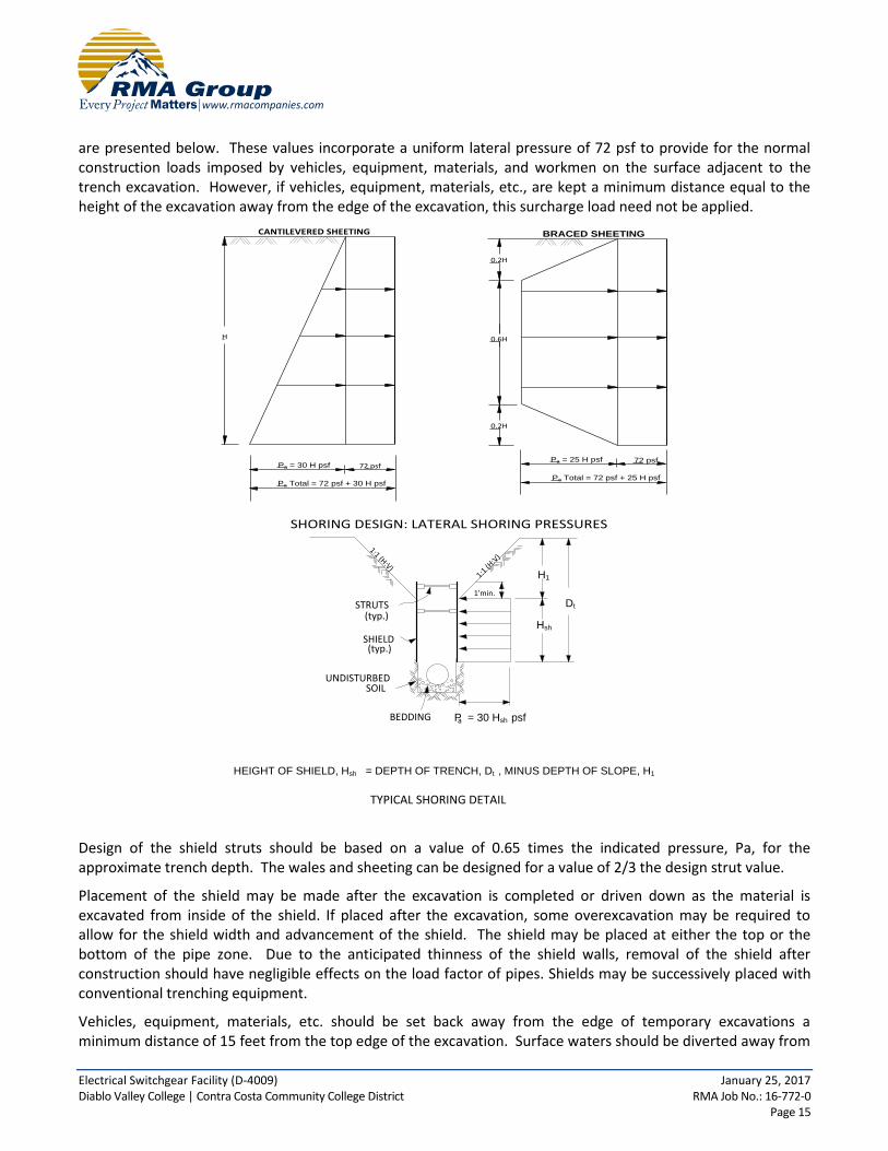
are presented below. These values incorporate a uniform lateral pressure of 72 psf to provide for the normal construction loads imposed by vehicles, equipment, materials, and workmen on the surface adjacent to the trench excavation. However, if vehicles, equipment, materials, etc., are kept a minimum distance equal to the height of the excavation away from the edge of the excavation, this surcharge load need not be applied.
SHORING DESIGN: LATERAL SHORING PRESSURES
BRACED SHEETING
H
CANTILEVERED SHEETING
72 psf
Pa Total = 72 psf + 30 H psf
Pa = 30 H psf
0.6H
0.2H
0.2H
Pa Total = 72 psf + 25 H psf
Pa = 25 H psf 72 psf
STRUTS(typ.)
SHIELD(typ.)
UNDISTURBED SOIL
BEDDING
1'min.
H1
Hsh
Dt
P = 30 Hsh psfa
HEIGHT OF SHIELD, Hsh = DEPTH OF TRENCH, Dt , MINUS DEPTH OF SLOPE, H1
TYPICAL SHORING DETAIL
1:1 (H
:V)
1:1 (H:V)
Design of the shield struts should be based on a value of 0.65 times the indicated pressure, Pa, for the approximate trench depth. The wales and sheeting can be designed for a value of 2/3 the design strut value.
Placement of the shield may be made after the excavation is completed or driven down as the material is excavated from inside of the shield. If placed after the excavation, some overexcavation may be required to allow for the shield width and advancement of the shield. The shield may be placed at either the top or the bottom of the pipe zone. Due to the anticipated thinness of the shield walls, removal of the shield after construction should have negligible effects on the load factor of pipes. Shields may be successively placed with conventional trenching equipment.
Vehicles, equipment, materials, etc. should be set back away from the edge of temporary excavations a minimum distance of 15 feet from the top edge of the excavation. Surface waters should be diverted away from

Electrical Switchgear Facility (D-4009) January 25, 2017 Diablo Valley College | Contra Costa Community College District RMA Job No.: 16-772-0 Page 16
temporary excavations and prevented from draining over the top of the excavation and down the slope face. During periods of heavy rain, the slope face should be protected with sandbags to prevent drainage over the edge of the slope, and a visqueen liner placed on the slope face to prevent erosion of the slope face.
Periodic observations of the excavations should be made by the geotechnical consultant to verify that the soil conditions have not varied from those anticipated and to monitor the overall condition of the temporary excavations over time. If at any time during construction conditions are encountered which differ from those anticipated, the geotechnical consultant should be contacted and allowed to analyze the field conditions prior to commencing work within the excavation.
Cal/OSHA construction safety orders should be observed during all underground work.
3.20 Utility Trench Backfill
The onsite fill soils will not be suitable for use as pipe bedding for buried utilities. All pipes should be bedded in a sand, gravel or crushed aggregate imported material complying with the requirements of the Standard Specifications for Public Works Construction Section 306-1.2.1. Crushed rock products that do not contain appreciable fines should not be utilized as pipe bedding and/or backfill. Bedding materials should be densified to at least 90% relative compaction (ASTM D1557) by mechanical methods. The geotechnical consultant should review and approve of proposed bedding materials prior to use.
The on-site soils are expected to be suitable as trench backfill provided they are screened of organic matter and cobbles over 12 inches in diameter. Trench backfill should be densified to at least 90% relative compaction (ASTM D1557). On-site granular soils may be water densified initially. Supplemental mechanical compaction methods may be required in finer ground soils to attain the required 90% relative compaction.
All utility trench backfill within street right of way, utility easements, under or adjacent to sidewalks, driveways, or building pads should be observed and tested by the geotechnical consultant to verify proper compaction. Trenches excavated adjacent to foundations should not extend within the footing influence zone defined as the area within a line projected at a 1:1 drawn from the bottom edge of the footing. Trenches crossing perpendicular to foundations should be excavated and backfilled prior to the construction of the foundations. The excavations should be backfilled in the presence of the geotechnical engineer and tested to verify adequate compaction beneath the proposed footing.
Cal/OSHA construction safety orders should be observed during all underground work.
3.21 Pavement Sections
Structural sections were designed using the procedures outlined in Chapter 630 of the California Highway Design Manual (Caltrans, 2008). This procedure uses the principle that the pavement structural section must be of adequate thickness to distribute the load from the design traffic index (TI) to the subgrade soils in such a manner that the stresses from the applied loads do not exceed the strength of the soil (R-value). A subgrade R-Value of 15 was assumed for use in the design of the pavement structural sections presented below.
Development of the design traffic indexes on the basis of a traffic study is beyond the scope of this report; however, our experience indicates that traffic index of 5 is typical for parking lots. We have provided alternate structural sections for each traffic index. Selection of the final pavement structural section should be based on economic considerations which are beyond the scope of this investigation.
Recommended structural sections are as follows:
Parking Lots (TI=5, R-Value=15): Parking Lots (TI=5, R-Value=15):

Electrical Switchgear Facility (D-4009) January 25, 2017 Diablo Valley College | Contra Costa Community College District RMA Job No.: 16-772-0 Page 17
3.0 inches of asphaltic concrete over 4.0 inches of asphalt concrete over 8.0 inches of crushed aggregate base 6.0 inches of crushed aggregate base
Portland cement concrete (PCC) pavements for areas which are not subject to traffic loads may be designed with a minimum thickness of 4.0 inches of Portland cement concrete on compacted native soils. If traffic loads are anticipated, PCC pavements should be designed for a minimum thickness of 6.0 inches of Portland cement concrete on 4.0 inches of crushed aggregate base.
Prior to paving, the subgrade soils should be scarified and the moisture adjusted to within 2% of the optimum moisture content. The subgrade soils should be compacted to a minimum of 90% relative compaction. All aggregate base courses should be compacted to a minimum of 95% relative compaction.
3.22 Plan Review
Once a formal grading and foundation plans are prepared for the subject property, this office should review the plans from a geotechnical viewpoint, comment on changes from the plan used during preparation of this report and revise the recommendations of this report where necessary.
3.23 Geotechnical Observation and Testing During Rough Grading
The geotechnical engineer should be contacted to provide observation and testing during the following stages of grading:
During the clearing and grubbing of the site.
During the demolition of any existing structures, buried utilities or other existing improvements.
During excavation and overexcavation of compressible soils.
During all phases of grading including ground preparation and filling operations.
When any unusual conditions are encountered during grading. A final geotechnical report summarizing conditions encountered during grading should be submitted upon completion of the rough grading operations.
3.24 Post-Grading Geotechnical Observation and Testing
After the completion of grading the geotechnical engineer should be contacted to provide additional observation and testing during the following construction activities:
During trenching and backfilling operations of buried improvements and utilities to verify proper backfill and compaction of the utility trenches.
After excavation and prior to placement of reinforcing steel or concrete within footing trenches to verify that footings are properly founded in competent materials.
During fine or precise grading involving the placement of any fills underlying driveways, sidewalks, walkways, or other miscellaneous concrete flatwork to verify proper placement, mixing and compaction of fills.
When any unusual conditions are encountered during construction.

Electrical Switchgear Facility (D-4009) January 25, 2017 Diablo Valley College | Contra Costa Community College District RMA Job No.: 16-772-0 Page 18
4.00 CLOSURE
The findings, conclusions and recommendations in this report were prepared in accordance with generally accepted engineering and geologic principles and practices. No other warranty, either expressed or implied, is made. This report has been prepared for Contra Costa Community College District to be used solely for design purposes. Anyone using this report for any other purpose must draw their own conclusions regarding required construction procedures and subsurface conditions.
The geotechnical and geologic consultant should be retained during the earthwork and foundation phases of construction to monitor compliance with the design concepts and recommendations and to provide additional recommendations as needed. Should subsurface conditions be encountered during construction that are different from those described in this report, this office should be notified immediately so that our recommendations may be re-evaluated.

FIGURES AND TABLES

Switchgear Facility (D-4009)Diablo Valley College | Contra Costa Community College District
RMA Project No.: 16-772-0Figure 1
SITE
Base Map: U.S. Geological Survey Walnut Creek Quadrangle, 2015
SITE LOCATION MAPScale: 1 inch ≈ 2000 feet

Switchgear Facility (D-4009)Diablo Valley College | Contra Costa Community College District
RMA Project No.: 16-772-0Figure 2
REGIONAL GEOLOGIC MAPScale: 1 inch ≈ 2,000 feet
Partial Legend
Qa – Holocene alluviumQoa – Pleistocene-Holocene older alluvium
Tbr, Tms, Tmc, Tsr, Tkm, Tkn, Tds, Tmg, Tmz – Tertiary Sedimentary Rock
Basemap: Dibblee and Minch, 2005, Geologic Map of Walnut Creek Quadrangle, Dibblee Geologic Foundation Map DF-149
SITE
Switchgear Facility (D-4009)Diablo Valley College | Contra Costa Community College District
RMA Project No.: 16-772-0Figure 3
Base Map: Google Earth Aerial Imagery, 2015
SITE GEOLOGIC MAPScale: 1 inch ≈ 20 feet
B-3-1
B-3-2
A
A
Proposed Switchgear Facility
Footprint (approx.)
Proposed Retaining Wall
Location (approx.)
Geologic Legend
Geologic Cross-SectionA A
Tbraf/Tbr
Contact
Approx. Boring LocationB-3-1
Briones SandstoneTbr
Artificial Fillaf

Switchgear Facility (D-4009)Diablo Valley College | Contra Costa Community College District
RMA Project No.: 16-772-0Figure 4
GEOLOGIC CROSS SECTIONHorizontal Scale: 1 inch ≈ 20 feet
Vertical Scale: 1 inch ≈ 10 feet
70
80
60
Ele
vatio
n in
Feet
50
A A
70
80
60
50
Ele
vatio
n in
Feet
B-3-2
B-3-1
Tbr
(Briones Sandstone)
Af
(Artificial Fill)
40
30
20
40
30
20
Proposed
Structure
Proposed
Retaining
Wall
Claystone
Siltstone
LEGEND
Silty Sandstone
Lean Clay
Refusal to
Drilling
Pavement Section

Switchgear Facility (D-4009)Diablo Valley College | Contra Costa Community College District
RMA Project No.: 16-772-0Figure 5
SITE
REGIONAL FAULT MAPScale: 1 inch ≈ 10 miles
Partial Legend
Red – Historic Fault Displacement
Orange – Holocene Fault Displacment
Green – Late Quaternary Fault Displacement
Purple – Quaternary Fault
Black – Pre-Quaternary Fault
Base Map: California Geological Survey Fault Activity Map, 2010

Electrical Switchgear Facility (D-4009) January 25, 2017 Diablo Valley College | Contra Costa Community College District RMA Job No.: 16-772-0 Table 1
Maximum Slip
Distance Distance Moment Rate
Fault Zone & geometry (km) (mi.) Magnitude (mm/yr)
Calaveras (rl-ss) 18 11 6.8 6.0
Concord (rl-ss) 2.8 1.7 6.2 4.0
Great Valley - Segment 4 (r) 40 25 6.6 1.5
Great Valley - Segment 5 (r) 31 19 6.5 1.5
Greenville - (rl-ss) 23 14 6.6 2.0
Hayward - (rl-ss) 19 12 6.7 9.0
Hunting Creek - Berryessa (ri-ss) 55 34 6.4 6.0
Maacama (rl-ss) 87 54 7.0 9.0
Monte Vista - Shannon (r) 61 38 6.7 0.4
Point Reyes (r) 67 42 7.0 0.3
San Andreas (rl-ss) 48 30 7.3 24.0
San Gregorio (rl-ss) 53 33 7.2 7.0
West Napa (rl-ss) 27 17 6.5 1.0
Zayante - Vergeles (rl-r) 98 61 7.0 0.1
Notes:
Fault geometry - (ss) strike slip, (r) reverse, (n) normal, (rl) right lateral, (ll) left lateral, (o) oblique
Fault and Seismic Data - California Geological Survey (Cao), 2003
NOTABLE FAULTS WITHIN 100 KILOMETERS AND SEISMIC DATA

Electrical Switchgear Facility (D-4009) January 25, 2017 Diablo Valley College | Contra Costa Community College District RMA Job No.: 16-772-0 Table 2
Epicentral
Distance
Date Event Magnitude (miles)
June 10, 1836 Near San Juan Bautista 6.4 78
June, 1938 San Juan Bautista - San Francisco 7.4 79
November 26, 1858 San Joase Region 6.2 54
February 26, 1964 Southeast of San Jose 6.1 62
March 5, 1864 East of San Francisco Bay 6.0 55
October 8, 1865 Santa Cruz Mountains 6.5 72
July 15, 1866 Western San Joaquin Valley 6.0 31
October 21, 1868 Bay Area - Hayward fault 7.0 64
April 19, 1892 Vacaville 6.6 63
March 31, 1998 Mara Island 6.4 86
June 11, 1903 San Jose 6.1 69
August 3, 1903 San Jose 6.2 63
April 18, 1906 Great San Francisco Earthqauke 7.8 86
July 1, 1911 Morgan Hill area 6.4 64
April 24, 1984 Morgan Hill 6.2 58
Oct. 17, 1989 Loma Prieta 6.9 80
Dec. 22, 2003 San Simeon 6.5 157
August 24, 2014 American Canyon 6.0 75
Notes:
Earthquake data: California Geological Survey online historic earthquake database, Magnitude ≥ 6.0
Magnitudes prior to 1932 are estimated from intensity.
Magnitudes after 1932 are moment, local or surface wave magnitudes.
Site Location:
Longitude: - 121.07004
Latitude: 37.96831
HISTORIC STRONG EARTHQUAKES SINCE 1836
SACRAMENTO - SAN FRANCISCO BAY REGION

APPENDIX A
FIELD INVESTIGATION
Electrical Switchgear Facility (D-4009) January 25, 2017 Diablo Valley College | Contra Costa Community College District RMA Job No.: 16-772-0 Page A - 1
APPENDIX A
FIELD INVESTIGATION
A-1.00 FIELD EXPLORATION A-1.01 Number of Borings Our subsurface investigation consisted of 2 borings drilled with a CME 45B drill rig. A-1.02 Location of Borings A Geologic Map showing the approximate locations of the borings is presented as Figure 3. A-1.03 Boring Logging Logs of borings were prepared by one of our staff and are attached in this appendix. The logs contain factual information and interpretation of subsurface conditions between samples. The strata indicated on these logs represent the approximate boundary between earth units and the transition may be gradual. The logs show subsurface conditions at the dates and locations indicated, and may not be representative of subsurface conditions at other locations and times. Identification of the soils encountered during the subsurface exploration was made using the field identification procedure of the Unified Soils Classification System (ASTM D2488). A legend indicating the symbols and definitions used in this classification system and a legend defining the terms used in describing the relative compaction, consistency or firmness of the soil are attached in this appendix. Bag samples of the major earth units were obtained for laboratory inspection and testing, and the in-place density of the various strata encountered in the exploration was determined

Electrical Switchgear Facility (D-4009) January 25, 2017 Diablo Valley College | Contra Costa Community College District RMA Job No.: 16-772-0 Page A - 2
Well graded gravel, gravel-sand mixtures.
Poorly graded gravel or gravel-sand mixtures,
Silty gravels, gravel-sand-silt mixtures.
Clayey gravels, gravel-sand-clay mixtures.
Well graded sands, gravelly sands, little or
Poorly graded sands or gravelly sands, little
Inorganic silts and very fine sands, rock floursilty or clayey fine sands or clayey silts
Inorganic clays of low to medium plasticity,gravelly clays, sandy clays, silty clays, lean
Organic silts and organic silty clays of low
Inorganic silts, micaceous or diatamaceousfine sandy or silty soils, elastic silts.
Inorganic clays of high plasticity, fat clays.
Organic clays of medium to high plasticity,
BOUNDARY CLASSIFICATIONS: Soils possessing characteristics of two groups are designated by combinations of group symbols.
Pt
OH
CH
MH
OL
CL
ML
SC
SM
SP
SW
GC
GM
GP
GW
MAJOR DIVISIONSGROUP
SYMBOLSTYPICAL NAMES
CLEAN
GRAVELS
GRAVELS
WITH FINES
GRAVELS
COARSE
GRAINED
SOILS
SANDS
CLEAN
SANDS
SANDS
WITH FINES
SILTS AND CLAYS
SILTS AND CLAYS
FINE
GRAINED
SOILS
HIGHLY ORGANIC SOILS
(More than 50% of
material is LARGER
than No. 200 sieve
size)
(More than 50% of
coarse fraction is
LARGER than the
No. 4 sieve size.
(More than 50% of
coarse fraction is
SMALLER than the
No. 4 sieve size)
(Appreciable
amount of fines)
(Little or no fines)
(Appreciable amt.
of fines)
(Little or no fines)
(More than 50% of
material is SMALLER
than No. 200 sieve
size)
(Liquid limit LESS than 50)
(Liquid limit GREATER than 50)
little or no fines.
little or no fines.
no fines.
or no fines.
Silty sands, sand-silt mixtures.
Clayey sands, sand-clay mixtures.
with slight plasticity
clays.
plasticity.
organic silts.
Peat and other highly organic soils.
P A
R T
I C
L E
S
I Z
E L
I M
I T
S
SIL
T O
R C
LA
Y
SA
ND
GR
AV
EL
CO
BB
LE
SB
OU
LD
ER
S
U.
S. S
T A
N D
A R
D S
I E
V E
S
I Z
E
FIN
EM
ED
IUM
CO
AR
SE
FIN
EC
OA
RS
E
No
. 2
00
No
. 4
0N
o.
10
No
. 4
3/4
in
.3
in
.1
2 i
n.
UNIFIED SOIL CLASSIFICATION SYSTEM

Electrical Switchgear Facility (D-4009) January 25, 2017 Diablo Valley College | Contra Costa Community College District RMA Job No.: 16-772-0 Page A - 3
I. SOIL STRENGTH/DENSITY
BASED ON STANDARD PENETRATION TESTS
Compactness of sand Consistency of clay
Penetration Resistance N (blows/Ft)
Compactness
Penetration Resistance N (blows/ft)
Consistency
0-4 4-10 10-30 30-50 >50
Very Loose Loose Medium Dense Dense Very Dense
<2 2-4 4-8
8-15 15-30 >30
Very Soft Soft Medium Stiff Stiff Very Stiff Hard
N = Number of blows of 140 lb. weight falling 30 in. to drive 2-in OD sampler 1 ft.
BASED ON RELATIVE COMPACTION
Compactness of sand Consistency of clay
% Compaction Compactness % Compaction Consistency
<75 75-83 83-90 >90
Loose Medium Dense Dense Very Dense
<80 80-85 85-90 >90
Soft Medium Stiff Stiff Very Stiff
II. SOIL MOISTURE
Moisture of sands Moisture of clays
% Moisture Description % Moisture Description
<5% 5-12% >12%
Dry Moist Very Moist
<12% 12-20% >20%
Dry Moist Very Moist, wet
SOIL DESCRIPTION LEGEND
Material DescriptionSamples
Dep
th(f
t)
Sam
ple
Typ
e
Blo
ws
(blo
ws/
ft)
Bu
lkSa
mp
le
Mo
istu
reC
on
ten
t(%
)
Dry
Den
sity
(pcf
)
USC
S This log contains factual information and interpretation of the subsurface conditions between the samples. The stratum indicated on this log represent the approximate boundary between earth units and the transition may be gradual. The log show subsurface conditions at the date and location indicated, and may not be representative of subsurface conditions at other locations and times.
Gra
ph
icSy
mb
ol
5
10
15
25
30
35
20
Date Drilled:
Logged By:
Location:
Drilling Equipment:
Borehole Diameter:
Drive Weights:
Exploratory Boring Log
P. Sorci
140 lbs. See Site Geologic Map
Boring No.Sheet of
Drop Height: 30"
- Groundwater
- End of Boring
S
T
- SPT Sample
- Modified California Tube Sample
- Bulk Sample
Sample Types: Symbols:*NoteAll blow counts associated with Modified California Sample are uncorrected. The sampler dimensions are as follows:
ID = 2.5" OD = 3"R - Ring Sample
RMA Project No.: 16-772-0Page A - 4
Switchgear Facility (D-4009)Diablo Valley College | Contra Costa Community College District
Elevation:
December 14, 2016
B-3-11 2
CME 45B, SF Auger, Auto Hammer
4 in.
Artificial Fill (Af): Brown sandy lean clay, about 20% fine to coarse sand, low to medium plasticity, moist, trace ¾” angular gravel, firm
4.5 inches of Asphalt Concrete over 6 inches of Aggregate Base
Briones Sandstone (Tbr): Yellow brown silty sandstone, fine to medium sand, about 15% silt, gray brown mottling, moist, cemented, very dense
T 50/6"
T 50/6"
S 86/11"
T 32
T 50/3"
S 50/3"
T 50/5"
S 85/10"
CL
--
--
26.7 93.5
104.116.7
86/11"
73.5 feet (approx.)
Silty fines content increases to about 45%
Brown sandy claystone, about 30% fine to medium sand, very moist, very firm

Samples
Dep
th(f
t)
Sam
ple
Typ
e
Blo
ws
(blo
ws/
ft)
Bu
lkSa
mp
le
Mo
istu
reC
on
ten
t(%
)
Dry
Den
sity
(pcf
)
USC
S
Gra
ph
icSy
mb
ol
45
50
55
65
70
75
60
Material DescriptionThis log contains factual information and interpretation of the subsurface conditions between the samples. The stratum indicated on this log represent the approximate boundary between earth units and the transition may be gradual. The log show subsurface conditions at the date and location indicated, and may not be representative of subsurface conditions at other locations and times.
Date Drilled:
Logged By:
Location:
Drilling Equipment:
Borehole Diameter:
Drive Weights:
Exploratory Boring Log
B. Wilson
140 lbs. See Site Geologic Map
Boring No.Sheet of
Drop Height: 30"
- Groundwater
- End of Boring
S
T
- SPT Sample
- Modified California Tube Sample
- Bulk Sample
Sample Types: Symbols:*NoteAll blow counts associated with Modified California Sample are uncorrected. The sampler dimensions are as follows:
ID = 2.5" OD = 3"R - Ring Sample
RMA Project No.: 16-772-0Page A - 5
Switchgear Facility (D-4009)Diablo Valley College | Contra Costa Community College District
Elevation:
Boring terminated at 45 feetGroundwater encountered at 30 feetHole backfilled with cement grout
December 14, 2016
B-3-12 2
CME 45B, SF Auger, Auto Hammer
4 in.
73.5 feet (approx.)
Claystone continues
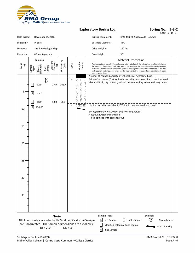
Material DescriptionSamples
Dep
th(f
t)
Sam
ple
Typ
e
Blo
ws
(blo
ws/
ft)
Bu
lkSa
mp
le
Mo
istu
reC
on
ten
t(%
)
Dry
Den
sity
(pcf
)
USC
S This log contains factual information and interpretation of the subsurface conditions between the samples. The stratum indicated on this log represent the approximate boundary between earth units and the transition may be gradual. The log show subsurface conditions at the date and location indicated, and may not be representative of subsurface conditions at other locations and times.
Gra
ph
icSy
mb
ol
5
10
15
25
30
35
20
Date Drilled:
Logged By:
Location:
Drilling Equipment:
Borehole Diameter:
Drive Weights:
Exploratory Boring Log
P. Sorci
140 lbs. See Site Geologic Map
Boring No.Sheet of
Drop Height: 30"
- Groundwater
- End of Boring
S
T
- SPT Sample
- Modified California Tube Sample
- Bulk Sample
Sample Types: Symbols:*NoteAll blow counts associated with Modified California Sample are uncorrected. The sampler dimensions are as follows:
ID = 2.5" OD = 3"R - Ring Sample
RMA Project No.: 16-772-0Page A - 6
Switchgear Facility (D-4009)Diablo Valley College | Contra Costa Community College District
Elevation:
December 14, 2016
B-3-21 1
CME 45B, SF Auger, Auto Hammer
4 in.
T 50/5"
S 50/5"
T 50/5"
S 15/0.5"
Boring terminated at 10 feet due to drilling refusalNo groundwater encounteredHole backfilled with cement grout
4 inches of Asphalt Concrete over 6 inches of Aggregate Base
18.8 85.9
17.9 105.7
62 feet (approx.)
Light brown siltstone, about 10% fine to medium sand, dry, hard
Briones Sandstone (Tbr): Yellow brown silty sandstone, fine to medium sand, about 15% silt, dry to moist, reddish brown mottling, cemented, very dense
--
--

APPENDIX B
LABORATORY TESTS

Electrical Switchgear Facility (D-4009) January 25, 2017 Diablo Valley College | Contra Costa Community College District RMA Job No.: 16-772-0 Page B - 1
APPENDIX B
LABORATORY TESTS
B-1.00 LABORATORY TESTS B-1.01 Maximum Density
Maximum density - optimum moisture relationships for the major soil types encountered during the field exploration were performed in the laboratory using the standard procedures of ASTM D1557. B-1.02 Soluble Sulfates and Chlorides
A test was performed on representative sample encountered during the investigation using the Caltrans Test Methods CTM 417 and CTM 422. B-1.03 Soil Reactivity (pH) and Electrical Conductivity (Ec)
A representative soil sample was tested for soil reactivity (pH) and electrical conductivity (Ec) using California Test Method 643. The pH measurement determines the degree of acidity or alkalinity in the soils. The Ec is a measure of the electrical resistivity and is expressed as the reciprocal of the resistivity. B-1.04 Particle Size Analysis
Particle size analysis was performed on representative samples of the major soils types in accordance to the standard test methods of the ASTM D422. The hydrometer portion of the standard procedure was not performed and the material retained on the #200 screen was washed. B-1.05 Direct Shear
Direct shear tests were performed on representative samples of the major soil types encountered in the test holes using the standard test method of ASTM D3080 (consolidated and drained). Tests were performed on remolded samples. Remolded samples were tested at 90 percent relative compaction.
Shear tests were performed on a direct shear machine of the strain-controlled type. To simulate possible adverse field conditions, the samples were saturated prior to shearing. Several samples were sheared at varying normal loads and the results plotted to establish the angle of the internal friction and cohesion of the tested samples. B-1.06 Moisture Determination
Moisture content of the soil samples was performed in accordance to standard method for determination of water content of soil by drying oven, ASTM D2216. The mass of material remaining after oven drying is used as the mass of the solid particles. B-1.07 Density of Split-Barrel Samples
Soil samples were obtained by using a split-barrel sampler in accordance to standard method of ASTM D1586 B-1.08 Test Results
Test results for all laboratory tests performed on the subject project are presented in this appendix.

Electrical Switchgear Facility (D-4009) January 25, 2017 Diablo Valley College | Contra Costa Community College District RMA Job No.: 16-772-0 Page B - 2
SAMPLE INFORMATION
Sample Number
Sample Description
Sample Location
Boring No. Depth (ft)
1 Silty Sand (SM) B-3-1 3.5
2 Silty Sand (SM) B-3-1 4-5
3 Silty Sand (SM) B-3-1 11.5
4 Silty Sand (SM) B-3-1 15-16
5 Silty Sand (SM) B-3-2 1-2.5
6 Silty Sand (SM) B-3-2 3
MAXIMUM DENSITY - OPTIMUM MOISTURE (Test Method: ASTM D1557)
Sample Number
Optimum Moisture (Percent)
Maximum Density (lbs/ft3)
2 17.8 110.3
SOLUBLE SULFATES AND CHLORIDES* (Test Method: CTM 417 and CTM 422)
Sample Number
Soluble Sulfate (ppm)
Chlorides (ppm)
5 80.3 15.7
*Testing performed by Sunland Analytical SOIL REACTIVITY (pH) AND ELECTRICAL CONDUCTIVITY* (Test Method: ASTM D4972)
Sample Number
pH
Resistivity (Ohm-cm)
5 7.85 1,550
*Testing performed by Sunland Analytical

Electrical Switchgear Facility (D-4009) January 25, 2017 Diablo Valley College | Contra Costa Community College District RMA Job No.: 16-772-0 Page B - 3
PERCENT PASSING #200 SIEVE (Test Method: ASTM D422)
Sample Location
Percent Passing #200 Sieve
1 16.1
3 23.3
4 46.0
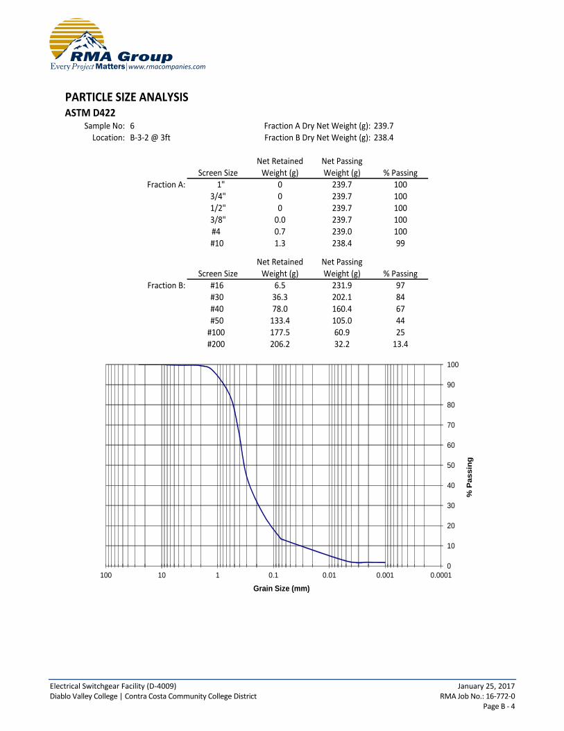
Electrical Switchgear Facility (D-4009) January 25, 2017 Diablo Valley College | Contra Costa Community College District RMA Job No.: 16-772-0 Page B - 4
PARTICLE SIZE ANALYSISASTM D422
Sample No: 6 Fraction A Dry Net Weight (g): 239.7Location: B-3-2 @ 3ft Fraction B Dry Net Weight (g): 238.4
Net Retained Net PassingScreen Size Weight (g) Weight (g) % Passing
Fraction A: 1" 0 239.7 100 3/4" 0 239.7 100 1/2" 0 239.7 100 3/8" 0.0 239.7 100 #4 0.7 239.0 100 #10 1.3 238.4 99
Net Retained Net PassingScreen Size Weight (g) Weight (g) % Passing
Fraction B: #16 6.5 231.9 97 #30 36.3 202.1 84 #40 78.0 160.4 67 #50 133.4 105.0 44#100 177.5 60.9 25#200 206.2 32.2 13.4
0
10
20
30
40
50
60
70
80
90
100
0.00010.0010.010.1110100
% P
assin
g
Grain Size (mm)

Electrical Switchgear Facility (D-4009) January 25, 2017 Diablo Valley College | Contra Costa Community College District RMA Job No.: 16-772-0 Page B - 5

APPENDIX C
GENERAL EARTHWORK AND GRADING SPECIFICATIONS
Electrical Switchgear Facility (D-4009) January 25, 2017 Diablo Valley College | Contra Costa Community College District RMA Job No.: 16-772-0 Page C - 1
APPENDIX C
GENERAL EARTHWORK AND GRADING SPECIFICATIONS
C-1.00 GENERAL DESCRIPTION
C-1.01 Introduction
These specifications present our general recommendations for earthwork and grading as shown on the approved grading plans for the subject project. These specifications shall cover all clearing and grubbing, removal of existing structures, preparation of land to be filled, filling of the land, spreading, compaction and control of the fill, and all subsidiary work necessary to complete the grading of the filled areas to conform with the lines, grades and slopes as shown on the approved plans. The recommendations contained in the geotechnical report of which these general specifications are a part of shall supersede the provisions contained hereinafter in case of conflict.
C-1.02 Laboratory Standard and Field Test Methods
The laboratory standard used to establish the maximum density and optimum moisture shall be ASTM D1557. The insitu density of earth materials (field compaction tests) shall be determined by the sand cone method (ASTM D1556), direct transmission nuclear method (ASTM D2922) or other test methods as considered appropriate by the geotechnical consultant. Relative compaction is defined, for purposes of these specifications, as the ratio of the in-place density to the maximum density as determined in the previously mentioned laboratory standard. C-2.00 CLEARING
C-2.01 Surface Clearing
All structures marked for removal, timber, logs, trees, brush and other rubbish shall be removed and disposed of off the site. Any trees to be removed shall be pulled in such a manner so as to remove as much of the root system as possible. C-2.02 Subsurface Removals A thorough search should be made for possible underground storage tanks and/or septic tanks and cesspools. If found, tanks should be removed and cesspools pumped dry. Any concrete irrigation lines shall be crushed in place and all metal underground lines shall be removed from the site.
C-2.03 Backfill of Cavities
All cavities created or exposed during clearing and grubbing operations or by previous use of the site shall be cleared of deleterious material and backfilled with native soils or other materials approved by the soil engineer. Said backfill

Electrical Switchgear Facility (D-4009) January 25, 2017 Diablo Valley College | Contra Costa Community College District RMA Job No.: 16-772-0 Page C - 2
shall be compacted to a minimum of 90% relative compaction.
C-3.00 ORIGINAL GROUND PREPARATION
C-3.01 Stripping of Vegetation
After the site has been properly cleared, all vegetation and topsoil containing the root systems of former vegetation shall be stripped from areas to be graded. Materials removed in this stripping process may be used as fill in areas designated by the soil engineer, provided the vegetation is mixed with a sufficient amount of soil to assure that no appreciable settlement or other detriment will occur due to decaying of the organic matter. Soil materials containing more than 3% organics shall not be used as structural fill. C-3.02 Removals of Non-Engineered Fills Any non-engineered fills encountered during grading shall be completely removed and the underlying ground shall be prepared in accordance to the recommendations for original ground preparation contained in this section. After cleansing of any organic matter the fill material may be used for engineered fill.
C-3.03 Overexcavation of Fill Areas
The existing ground in all areas determined to be satisfactory for the support of fills shall be scarified to a minimum depth of 6 inches. Scarification shall continue until the soils are broken down and free from lumps or clods and until the scarified zone is uniform. The moisture content of the scarified zone shall be adjusted to within 2% of optimum moisture. The scarified zone shall then be uniformly compacted to 90% relative compaction. Where fill material is to be placed on ground with slopes steeper than 5:1 (H:V) the sloping ground shall be benched. The lowermost bench shall be a minimum of 15 feet wide, shall be a minimum of 2 feet deep, and shall expose firm material as determined by the geotechnical consultant. Other benches shall be excavated to firm material as determined by the geotechnical consultant and shall have a minimum width of 4 feet. Existing ground that is determined to be unsatisfactory for the support of fills shall be overexcavated in accordance to the recommendations contained in the geotechnical report of which these general specifications are a part.
C-4.00 FILL MATERIALS
C-4.01 General
Materials for the fill shall be free from vegetable matter and other deleterious substances, shall not contain rocks or lumps of a greater dimension than is recommended by the geotechnical consultant, and shall be approved by the geotechnical consultant. Soils of poor gradation, expansion, or strength properties shall be placed in areas designated by the geotechnical consultant or shall be mixed with other soils providing satisfactory fill material.
C-4.02 Oversize Material
Oversize material, rock or other irreducible material with a maximum dimension greater than 12 inches, shall not be placed in fills, unless the location, materials, and disposal methods are specifically approved by the geotechnical consultant. Oversize material shall be placed in such a manner that nesting of oversize material does not occur and in such a manner that the oversize material is completely surrounded by fill material compacted to a minimum of 90% relative compaction. Oversize material shall not be placed within 10 feet of finished grade without the

Electrical Switchgear Facility (D-4009) January 25, 2017 Diablo Valley College | Contra Costa Community College District RMA Job No.: 16-772-0 Page C - 3
approval of the geotechnical consultant.
C-4.03 Import
Material imported to the site shall conform to the requirements of Section 4.01 of these specifications. Potential import material shall be approved by the geotechnical consultant prior to importation to the subject site.
C-5.00 PLACING AND SPREADING OF FILL
C-5.01 Fill Lifts
The selected fill material shall be placed in nearly horizontal layers which when compacted will not exceed approximately 6 inches in thickness. Thicker lifts may be placed if testing indicates the compaction procedures are such that the required compaction is being achieved and the geotechnical consultant approves their use. Each layer shall be spread evenly and shall be thoroughly blade mixed during the spreading to insure uniformity of material in each layer.
C-5.02 Fill Moisture
When the moisture content of the fill material is below that recommended by the soils engineer, water shall then be added until he moisture content is as specified to assure thorough bonding during the compacting process. When the moisture content of the fill material is above that recommended by the soils engineer, the fill material shall be aerated by blading or other satisfactory methods until the moisture content is as specified.
C-5.03 Fill Compaction
After each layer has been placed, mixed, and spread evenly, it shall be thoroughly compacted to not less than 90% relative compaction. Compaction shall be by sheepsfoot rollers, multiple-wheel pneumatic tired rollers, or other types approved by the soil engineer. Rolling shall be accomplished while the fill material is at the specified moisture content. Rolling of each layer shall be continuous over its entire area and the roller shall make sufficient trips to insure that the desired density has been obtained.
C-5.04 Fill Slopes
Fill slopes shall be compacted by means of sheepsfoot rollers or other suitable equipment. Compacting of the slopes may be done progressively in increments of 3 to 4 feet in fill height. At the completion of grading, the slope face shall be compacted to a minimum of 90% relative compaction. This may require track rolling or rolling with a grid roller attached to a tractor mounted side-boom. Slopes may be over filled and cut back in such a manner that the exposed slope faces are compacted to a minimum of 90% relative compaction. The fill operation shall be continued in six inch (6") compacted layers, or as specified above, until the fill has been brought to the finished slopes and grades as shown on the accepted plans.

Electrical Switchgear Facility (D-4009) January 25, 2017 Diablo Valley College | Contra Costa Community College District RMA Job No.: 16-772-0 Page C - 4
C-5.05 Compaction Testing
Field density tests shall be made by the geotechnical consultant of the compaction of each layer of fill. Density tests shall be made at locations selected by the geotechnical consultant. Frequency of field density tests shall be not less than one test for each 2.0 feet of fill height and at least every one thousand cubic yards of fill. Where fill slopes exceed four feet in height their finished faces shall be tested at a frequency of one test for each 1000 square feet of slope face. Where sheepsfoot rollers are used, the soil may be disturbed to a depth of several inches. Density reading shall be taken in the compacted material below the disturbed surface. When these readings indicate that the density of any layer of fill or portion thereof is below the required density, the particular layer or portion shall be reworked until the required density has been obtained. C-6.00 SUBDRAINS
C-6.01 Subdrain Material
Subdrains shall be constructed of a minimum 4-inch diameter pipe encased in a suitable filter material. The subdrain pipe shall be Schedule 40 Acrylonitrile Butadiene Styrene (ABS) or Schedule 40 Polyvinyl Chloride Plastic (PVC) pipe or approved equivalent. Subdrain pipe shall be installed with perforations down. Filter material shall consist of 3/4" to 1 1/2" clean gravel wrapped in an envelope of filter fabric consisting of Mirafi 140N or approved equivalent.
C-6.02 Subdrain Installation
Subdrain systems, if required, shall be installed in approved ground to conform the approximate alignment and details shown on the plans or herein. The subdrain locations shall not be changed or modified without the approval of the geotechnical consultant. The geotechnical consultant may recommend and direct changes in the subdrain line, grade or material upon approval by the design civil engineer and the appropriate governmental agencies.
C-7.00 EXCAVATIONS
C-7.01 General
Excavations and cut slopes shall be examined by the geotechnical consultant. If determined necessary by the geotechnical consultant, further excavation or overexcavation and refilling of overexcavated areas shall be performed, and/or remedial grading of cut slopes shall be performed.
C-7.02 Fill-Over-Cut Slopes
Where fill-over-cut slopes are to be graded the cut portion of the slope shall be made and approved by the geotechnical consultant prior to placement of materials for construction of the fill portion of the slope.
C-8.00 TRENCH BACKFILL

Electrical Switchgear Facility (D-4009) January 25, 2017 Diablo Valley College | Contra Costa Community College District RMA Job No.: 16-772-0 Page C - 5
C-.01 General
Trench backfill within street right of ways shall be compacted to 90% relative compaction as determined by the ASTM D1557 test method. Backfill may be jetted as a means of initial compaction; however, mechanical compaction will be required to obtain the required percentage of relative compaction. If trenches are jetted, there must be a suitable delay for drainage of excess water before mechanical compaction is applied.
C-9.00 SEASONAL LIMITS
C-9.01 General
No fill material shall be placed, spread or rolled while it is frozen or thawing or during unfavorable weather conditions. When the work is interrupted by heavy rain, fill operations shall not be resumed until field tests by the soils engineer indicate that the moisture content and density of the fill are as previously specified.
C-10.00 SUPERVISION
C-10.01 Prior to Grading
The site shall be observed by the geotechnical consultant upon completion of clearing and grubbing, prior to the preparation of any original ground for preparation of fill. The supervisor of the grading contractor and the field representative of the geotechnical consultant shall have a meeting and discuss the geotechnical aspects of the earthwork prior to commencement of grading.
C-10.02 During Grading
Site preparation of all areas to receive fill shall be tested and approved by the geotechnical consultant prior to the placement of any fill. The geotechnical consultant or his representative shall observe the fill and compaction operations so that he can provide an opinion regarding the conformance of the work to the recommendations contained in this report.

Electrical Switchgear Facility (D-4009) January 25, 2017 Diablo Valley College | Contra Costa Community College District RMA Job No.: 16-772-0 Page C - 6
RETAINING WALL DRAINAGE DETAIL
Soil backfill, compacted to
90% relative compaction*
Filter fabric envelope
(Mirafi 140N or approved
equivalent) **
Minimum of 1 cubic foot
3" diameter perforated
PVC pipe (schedule 40 or
equivalent) with perforations
oriented down as depicted
minimum 1% gradient to
suitable outlet.
3" min.
Wall footing
Compacted fill
Finished Grade
Retaining wall
Wall waterproofing
per architect's
specifications
* Based on ASTM D1557
** If class 2 permeable material (See
gradation to left) is used in place of
3/4" - 1 1/2" gravel. Filter fabric may
be deleted. Class 2 permeable material
compacted to 90% relative compaction. *
SPECIFICATIONS FOR CLASS 2
PERMEABLE MATERIAL
(CAL TRANS SPECIFICATIONS)
Sieve Size % Passing1"
3/4"
3/8"
No.4
No.8
No.30
No.50
No.200 0-3
0-7
5-15
18-33
25-40
40-100
90-100
100
per linear foot of 3/4"crushed rock
50 feet on center to a
joints or outlet drain atProvide open cell head
suitable drainage device
.
..
.
.
.
.
..
.
.
.
.

APPENDIX D
REFERENCES

Electrical Switchgear Facility (D-4009) January 25, 2017 Diablo Valley College | Contra Costa Community College District RMA Job No.: 16-772-0 Page D - 1
APPENDIX D
REFERENCES
1. Bryant, W.A. and Hart, E.W., 2007, Fault-Rupture Hazard Zones in California: California Department of Conservation, Division of Mines and Geology Special Publication 42, Interim Revision 2007 and online updates.
2. California Building Standards Commission, 2016 California Building Code.
3. California Department of Water Resources, 2015, Online Water Data Library, http://www.water.ca.gov/waterdatalibrary/.
4. California Division of Mines and Geology, 1993, Special Studies Zone Map, Walnut Creek Quadrangle.
5. California Geological Survey, 2013, Checklist for the Review of Engineering Geology and Seismology Reports for California Public Schools, Hospitals, and Essential Services Buildings, Note 48.
6. Caltrans, 2008, California Department of Transportation Highway Design Manual, Chapter 630 – Flexible Pavement, updated July 24, 2009.
7. Cao, Y. and others, 2003, The Revised 2002 California Probabilistic Seismic Hazard Maps, June 2003.
8. Churchill, R.K. and Hill, R.L., 2000, A General Location Guide for Ultramafic Rocks in California – Areas More Likely to Contain Naturally Occurring Asbestos: Department of Conservation, Division of Mines and Geology Open-File Report 2000-19.
9. City of Pleasant Hill, 2003, General Plan.
10. Dibblee, T.W. and Minch, J.A., 2005, Geologic Map of the Walnut Creek Quadrangle, Contra Costa County, California: Dibblee Foundation Map DF-149.
11. Federal Emergency Management Agency, 2009, Flood Insurance Rate Map (FIRM) Map #06013C0279F dated June 16, 2009.
12. Google Earth, Aerial Photographs, 2015.
13. Historicaerials.com, Aerial Photographs, 1946, 1949, 1968, 1979, 2012.
14. Jennings, C.W., and Bryant, W.A, 2010, Fault Activity Map of California, California Geological Survey, Geologic Data Map No. 6.
15. Martin, G.R. and Lew, M., 1999, Recommended Procedures for Implementation of DMG Special Publication 117, Guidelines for Analyzing and Mitigating Liquefaction Hazards in California, Southern California Earthquake Center publication.
16. Miller, Dan C., 1989, Potential Hazards from Future Volcanic Eruptions in California: U.S. Geological Survey Bulletin 1847.
Electrical Switchgear Facility (D-4009) January 25, 2017 Diablo Valley College | Contra Costa Community College District RMA Job No.: 16-772-0 Page D - 2
17. Seed, H.B. and Whitman, R.V., 1970, Design of Earth Structures for Dynamic Loads in American Society of Civil Engineers Specialty Conference State-of-the Art Paper, Lateral Stresses in the Ground and Design of Earth-Retaining Structures.
18. U.S. Army Corps of Engineers, 2003, Engineering and Design - Stability Analysis of Concrete Structures, Publication CECW-E, Circular No. 1110-2-6058, Appendix G, http://www.usace.army.mil/publications/eng-circulars/ec1110-2-6058/
19. U.S. Geological Survey, 2016, Seismic Design Maps Calculator, ASCE 7-10 Standard, http://ehp2-earthquake.wr.usgs.gov/designmaps/us/report.php.