Geotechnical Investigation Robinson Park Development Corp ...
45
Geotechnical Investigation Robinson Park Development Corp. 17 Robinson Avenue, Ottawa, ON Project No. 163808203 Task 104 November 2013
Transcript of Geotechnical Investigation Robinson Park Development Corp ...

Geotechnical Investigation
Robinson Park Development Corp.
17 Robinson Avenue, Ottawa, ON
Project No. 163808203 Task 104
November 2013

GEOTECHNICAL INVESTIGATION November 2013
i
Table of Contents
1.0 INTRODUCTION ................................................................................................................ 1
2.0 SITE DESCRIPTION AND BACKGROUND ....................................................................... 1
3.0 SCOPE OF WORK ............................................................................................................. 1
4.0 METHOD OF INVESTIGATION .......................................................................................... 2
4.1 GEOTECHNICAL FIELD INVESTIGATION......................................................................... 2
4.2 SURVEYING ....................................................................................................................... 3
5.0 RESULTS OF INVESTIGATION ......................................................................................... 3
5.1 SUBSURFACE INFORMATION .......................................................................................... 3 5.1.1 Surficial Materials ................................................................................................. 3 5.1.2 Till ........................................................................................................................ 3 5.1.3 Bedrock ................................................................................................................ 4
5.2 GROUNDWATER ............................................................................................................... 4
6.0 DISCUSSION AND RECOMMENDATIONS ....................................................................... 4
6.1 SITE GRADING AND PREPARATION ................................................................................ 4 6.1.1 Building Footprint ................................................................................................. 4 6.1.2 Paved Areas ......................................................................................................... 5
6.2 FOUNDATIONS .................................................................................................................. 5
6.3 BELOW GRADE PARKING ENTRANCE AND RETAINING WALLS................................... 6 6.3.1 Below Grade Parking Entrance ............................................................................ 6 6.3.2 Retaining Walls .................................................................................................... 6
6.4 TEMPORARY EXCAVATIONS AND BACKFILLING ........................................................... 7 6.4.1 General Excavations ............................................................................................ 7 6.4.2 Foundation Backfill ............................................................................................... 7 6.4.3 Pipe Bedding and Backfill ..................................................................................... 7 6.4.4 Groundwater and Dewatering ............................................................................... 8
6.5 CONCRETE FLOOR SLABS .............................................................................................. 8
6.6 CEMENT TYPE AND CORROSION POTENTIAL ............................................................... 9
6.7 PAVEMENT STRUCTURE RECOMMENDATIONS ............................................................ 9
6.8 SEISMIC SITE CLASSIFICATION .....................................................................................10
6.9 LATERAL EARTH PRESSURES .......................................................................................11
7.0 CLOSURE .........................................................................................................................14

GEOTECHNICAL INVESTIGATION November 2013
ii
List of Tables Table 6.1: Geotechnical Bearing Resistance for Foundations on Native Till .............................. 5 Table 6.2: pH, Sulphate, Chloride and Resistivity Analysis Results ........................................... 9 Table 6.3: Recommended Pavement Design ...........................................................................10 Table 6.4: Parameters for Seismic Site Classification ..............................................................11 Table 6.5: Lateral Earth Pressure Parameters .........................................................................11 Table 6.6: Unfactored Friction Coefficients ...............................................................................11 Table 6.7: Combined Coefficients of Static and Seismic Earth Pressure ..................................13
List of Appendices
APPENDIX A Statement of General Conditions
APPENDIX B Key Plan
Borehole Location Plan with Existing Site
Borehole Location Plan with Proposed Development
APPENDIX C Symbols and Terms Used on Borehole and Test Pit Records
Borehole Records
Field Rock Core Log
APPENDIX D Laboratory Test Results
APPENDIX E Bedrock Core Photos
APPENDIX F Factor of Safety Against Liquefaction (FSL) with Depth Profile

GEOTECHNICAL INVESTIGATION November 2013
1
1.0 Introduction
This report presents the results of the Geotechnical Investigation carried out for the proposed
multi-unit apartment building at 17 Robinson Avenue in Ottawa, ON. The work was carried out
in general accordance with our scope of work for a geotechnical investigation outlined in
Stantec’s proposal.
This report has been prepared specifically and solely for the project described herein. It
presents the factual results of the investigation and provides geotechnical recommendations for
the design and construction of the proposed building.
2.0 Site Description and Background
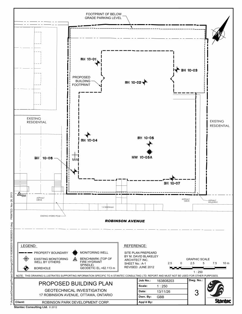
It is understood that the proposed building is to be located at the civic addresses 17, 19 and 23
Robinson Avenue in Ottawa, Ontario. The proposed footprint of the building has an
approximate area of 654 m2. The building will be a low rise multi-unit structure with six storeys
above ground and one below ground. The development will include below ground parking with
a concrete ramp entering from Robinson Avenue and asphalt walkways. The building is
assumed to be supported on strip or spread footings. The location of the proposed building is
shown on Drawing No. 3 in Appendix B.
The site for the proposed building is currently occupied with three residential units. The existing
units are two storeys high and occupy civic addresses 17, 19 and 23 Robinson Avenue. The
footprints of the existing units are about 65 m2, 90 m2 and 100 m2, respectively. The area
surrounding the units consists of grassed areas and both gravel and asphalt driveways.
Existing residential houses are located along the east and west property boundaries. Robinson
Avenue is positioned southeast from the site, and is an urban cross section with a concrete
sidewalk and a concrete curb situated between the site and the road.
Based on soil mapping of the area, the subsurface conditions consist of till overlying shale
bedrock. The depth to bedrock is estimated to be between 5 and 15 m below ground surface,
and the shale bedrock is the Carlsbad Formation.
3.0 Scope of Work
The scope of work for this geotechnical investigation included the following:
Advance seven boreholes, three of the boreholes drilled to refusal on bedrock, and four boreholes drilled to 8.5 m below the ground surface or to refusal, if shallower.
Perform standard penetration tests (SPT) while collecting soil samples at regular intervals.
GEOTECHNICAL INVESTIGATION November 2013
2
Install a monitoring well within one borehole. Decommissioning the well is not included within the scope of the project.
Characterize the soils on site with laboratory tests including soil resistivity and pH, gradation, moisture contents and Atterberg Limits.
Survey the ground surface elevations at the borehole locations with reference to a local benchmark.
Prepare a Geotechnical Investigation Report for the proposed building. The report will include; summary of the field investigation results and observations, laboratory test results, a borehole location plan, and geotechnical engineering recommendations for the design and construction of the project including:
Soil and bedrock conditions;
Site preparation, demolition, excavation and backfilling;
Groundwater levels and dewatering recommendations;
Seismic Site Class;
ULS and SLS Geotechnical Resistances for foundations;
Pavement structure for paved areas.
Concrete structure for ramp
4.0 Method of Investigation
4.1 GEOTECHNICAL FIELD INVESTIGATION
Prior to carrying out the investigation, Stantec Consulting Limited (Stantec) personnel marked
out the proposed borehole locations at the site. As a component of our standard procedures
and due diligence, Stantec contracted USL-1 to ensure that all borehole locations were clear of
all public and private underground utilities.
The field drilling program was carried out between July 26, 2010 and July 28, 2010. The seven
boreholes were advanced, at the locations shown on Drawing 2 in Appendix B, with a truck
mounted CME 75 auger drill rig. The subsurface stratigraphy encountered in each borehole
was recorded in the field by Stantec personnel while performing Standard Penetration Tests
(SPT). Split spoon samples were collected at regular depth intervals in each borehole. Bedrock
was cored with NQ size coring equipment. Bedrock cores were logged in the field and returned
to our office.
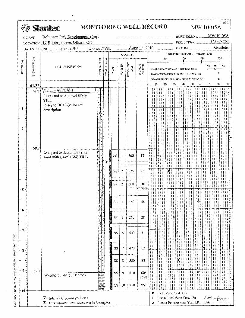
A 50 mm diameter monitoring well was installed within borehole MW10-05A. The monitoring
well construction consisted of; well screen between elevation 48 m and 51 m, silica sand to
approximately 0.6 m above the screen, 0.6 m thick bentonite seal and backfilled with auger
cutting to ground surface.
Following drilling, all boreholes were backfilled with auger cuttings. Samples were returned to
the laboratory and subjected to detailed visual examination and additional classification by a
geotechnical engineer. Selected samples were tested for soil resistivity, pH, chlorides, soluble
sulphate, gradation, and moisture contents. Results of this testing are shown on the Borehole
Records and in Appendix D.

GEOTECHNICAL INVESTIGATION November 2013
3
Samples will be stored for a period of one (1) month after issuance of this report unless we are
otherwise directed by the client.
4.2 SURVEYING
The ground surface elevation at each test hole was surveyed with reference to a geodetic
benchmark established at the fire hydrant located in front of civic address 13-11 Robinson
Avenue, approximately 9 m southwest from the southernmost corner of the site. The location of
the benchmark is shown on Drawing 2 of Appendix B and had a geodetic elevation of 62.113 m.
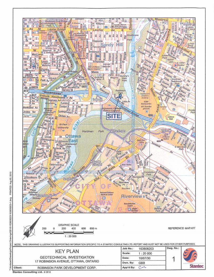
5.0 Results of Investigation
The location of the site is shown on Drawing No. 1 in Appendix B. At the time of the
investigation, the site for the proposed building was occupied with three residential units. The
area surrounding the units on site consisted of grassed areas and both gravel and asphalt
driveways as shown in Drawing No. 2 in Appendix B.
5.1 SUBSURFACE INFORMATION
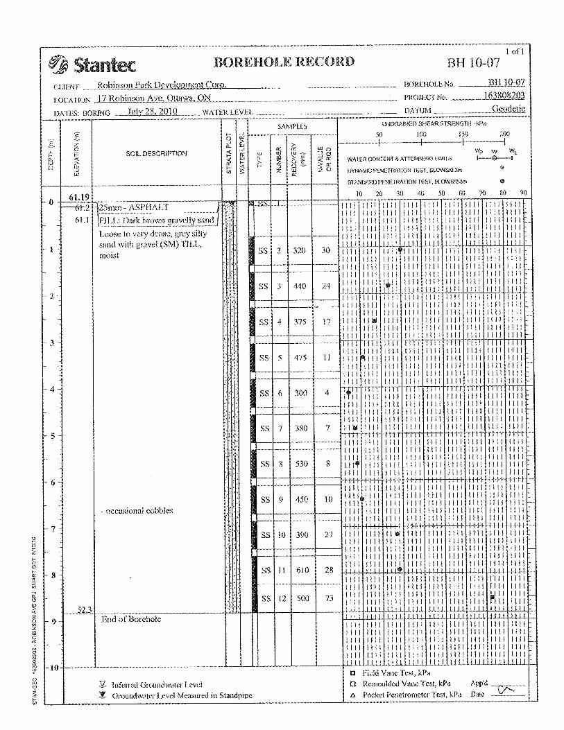
In general, the subsurface profile at this site consisted of a surficial layer of topsoil, gravel or
asphalt over fill underlain with a deposit of silty sand with gravel till over shale bedrock.
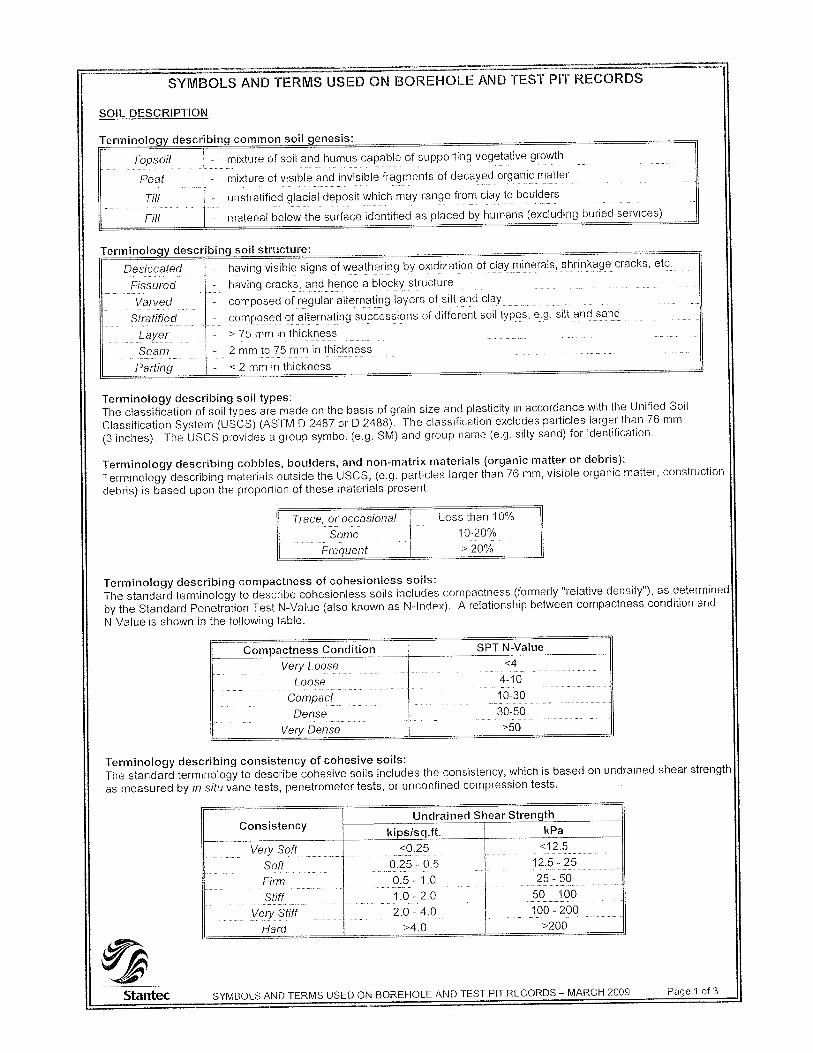
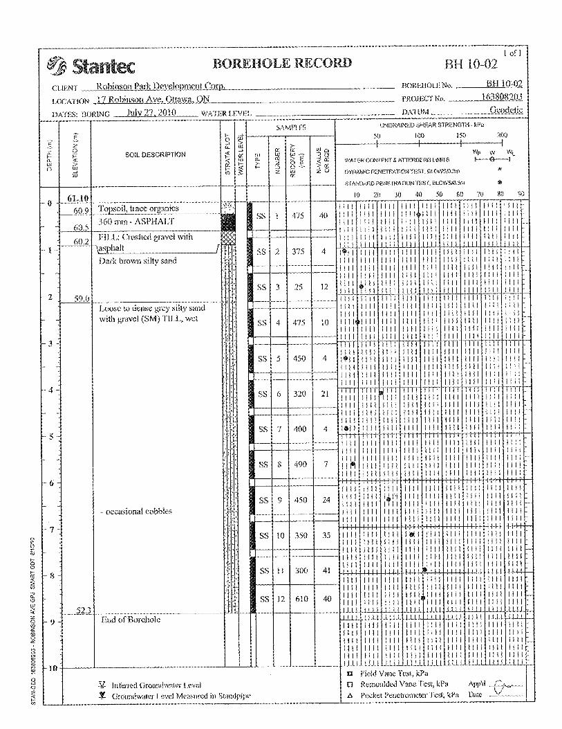
The subsurface conditions observed are presented on the Borehole Records in Appendix C. An
explanation of symbols and terms used is provided. A summary of the laboratory results, which
are included in Appendix D, is provided below.
5.1.1 Surficial Materials
Topsoil was encountered in two of the boreholes, the topsoil varied from 250 mm to 610 mm in
thickness. Generally, the surficial materials were variations of dark brown sand with gravel and
organics. A layer of asphalt was encountered within boreholes BH10-02, BH10-03, BH10-05
and BH10-07. The thickness of the asphalt varied between 25 mm to 360 mm. Underlying the
asphalt a thin layer of fill was encountered.
5.1.2 Till
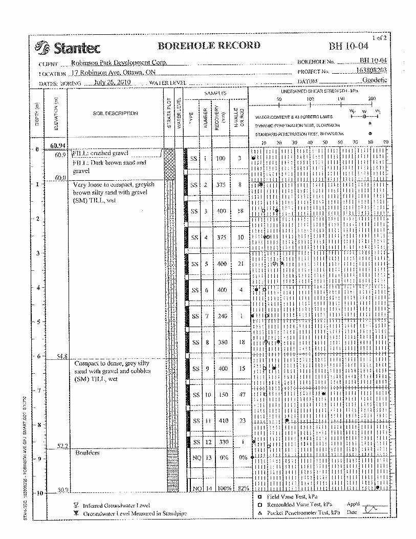
A layer of till was encountered underlying the surficial materials. The till consisted of silty sand
with gravel and varying amounts of cobbles and boulders. Standard Penetration Tests on the
material ranged between 4 to >50 which indicates a loose to dense state. The moisture content
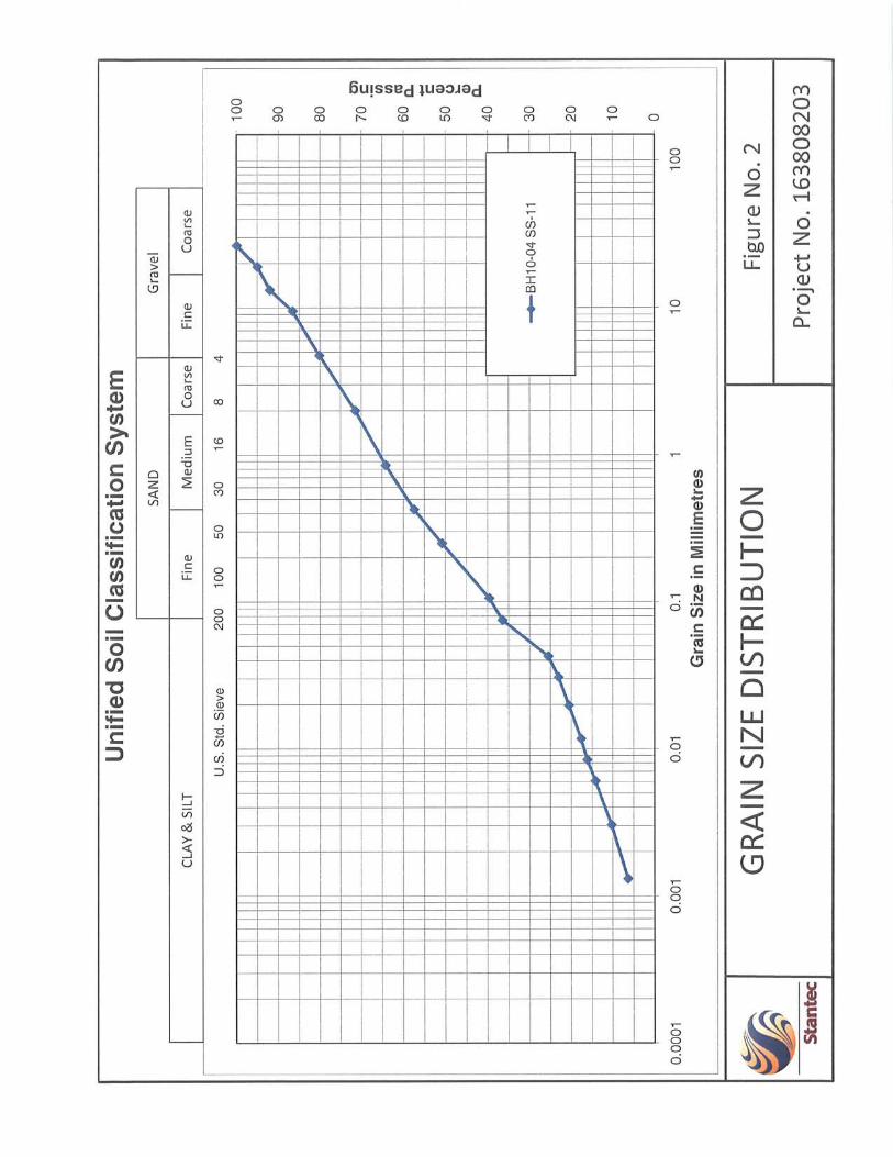
of this material ranged from 7.1 % to 12.8 %. Gradation tests performed on this material ranges
between 19% and 22% gravel, between 44% and 45% sand, and between 34% and 35% fines
(silt and clay). The gradation results are presented on Figures 1 and 2 in Appendix D. This
material can be classified as a silty sand with some gravel SM, according to the Unified Soil
Classification System (USCS).

GEOTECHNICAL INVESTIGATION November 2013
4
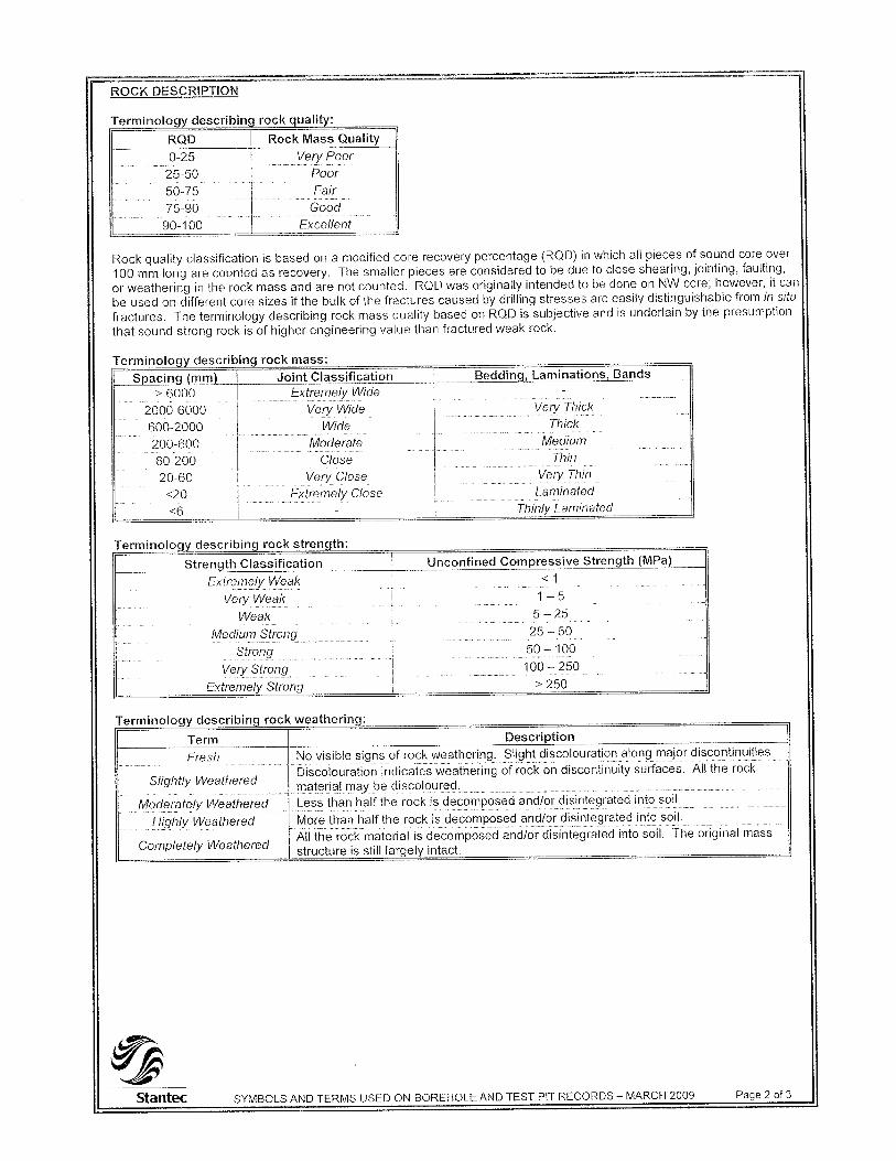
5.1.3 Bedrock
Shale bedrock was encountered in borehole BH10-04 and MW10-05A. The depth of the top of
bedrock ranged from 8.7 m to 9.1 m below ground surface. The shale bedrock cored within
BH10-04 was observed to be moderately weathered. The bedrock Rock Quality Designation
(RQD) values ranged from 9% to 82% within the two samples that were cored from BH10-04.
The lower RQD value is due to the drilling equipment. Photographs of the rock cores are
presented in Appendix E.
Unconfined compressive strength tests on samples of rock core yielded strengths of 56 and 70
MPa.
5.2 GROUNDWATER
Groundwater level was measured within the monitoring well installed in MW10-05A.
Groundwater was measured on August 4, 2010 one week after completion of drilling. The
groundwater level in MW10-05A was measured at 3.70m below ground surface, which
corresponds to a groundwater elevation of 57.51 m.
6.0 Discussion and Recommendations
The following geotechnical issues should be considered during design activities:
Conventional spread footings founded on native material (till) are appropriate for the design of structures at this site.
Groundwater was not encountered at depths within the proposed depth of construction. It is anticipated that groundwater elevations will fluctuate throughout the year and will likely rise to the level of the below grade parking. The building design should include a perimeter and floor slab drainage system and damp-proofing.
The recommended Site Classification for Seismic Site Response for the site is Site Class D in accordance with NBCC 2006.
The excavation for the proposed building will be approximately 3.0 to 3.5 m below the ground surface. The excavation will be approximately 1.8 m away from the existing residential buildings. The excavation will need to be shored; the shoring system should be designed to ensure the stability of the existing residential buildings.
6.1 SITE GRADING AND PREPARATION
6.1.1 Building Footprint
Currently there are three residential units present on site. The existing units are two storeys in
height, with footprints of approximately 65 m2, 90 m2 and 100 m2, respectively. Underground
services have been located on site within the footprint of the proposed building. Water and
sewer services are connected to the existing units, telephone and cable utilities are present
overhead, a hydro pole is located on the southeast corner of the site and a gas line runs north of
the sidewalk. All existing residential units and utilities should be removed from site.

GEOTECHNICAL INVESTIGATION November 2013
5
The area surrounding the three units consists of grassed areas and both gravel and asphalt
driveways. All existing topsoil, asphalt, concrete (foundations), services, fill and any deleterious
materials should be removed from beneath the footprint of the building, the footings and the
zone of influence of all footings. The zone of influence is defined by a line drawn at 1 horizontal
to 1 vertical, outward and downward from the edge of the footings.
Prepared subgrade surfaces should be inspected by experienced geotechnical personnel prior
to placement of either Structural Fill or concrete. All soft or disturbed areas revealed during
subgrade excavation or inspection should be removed and replaced with approved Structural
Fill, as defined below.
Structural Fill should conform to the requirements of OPSS Granular B Type II or OPSS
Granular A. Structural Fill placed beneath building should contain no recycled materials such as
concrete or asphalt. It should be compacted in lifts no thicker than 300 mm to at least 100%
Standard Proctor Maximum Dry Density (SPMDD). This material should be tested and
approved by a Geotechnical Engineer prior to delivery to the site.
Earth removals should be inspected by a geotechnical engineer to ensure that all unsuitable
materials are removed prior to placement of fill. Inspection and testing services will be critical to
ensure that all fill used is suitable and is placed and compacted to the required degree.
6.1.2 Paved Areas
All vegetation, topsoil, asphalt and other deleterious material should be removed from beneath
pavement areas. The subgrade should be proof rolled in the presence of geotechnical
personnel. All soft areas revealed during proof rolling or subgrade inspections should
excavated to a maximum depth of 500 mm and replaced with compacted Subgrade Fill.
6.2 FOUNDATIONS
The foundations for the proposed building may be supported on spread footings provided that
the foundation preparation work described in Section 6.1 above is carried out. Spread footings
should be placed on clean undisturbed native till.
Table 6.1 provides Geotechnical Bearing Resistances for shallow foundations on native till. The
values have been calculated assuming a footing embedment depth of 0.5 m.
Table 6.1: Geotechnical Bearing Resistance for Foundations on Native Till
Foundation Type Footing Width (m) Geotechnical Resistances - Till
ULS (kPa) SLS (kPa)
Strip Footing 0.8 130 130
Strip Footing 1.0 150 150
Square Footing 1.0 170 150
Square Footing 2.0 210 130
Square Footing 3.0 260 100
GEOTECHNICAL INVESTIGATION November 2013
6
The factored geotechnical bearing resistance at Ultimate Limit States (ULS) incorporates a
resistance factor of 0.5. The geotechnical reaction at Serviceability Limit States (SLS) is the
bearing pressure that corresponds to 25 mm of settlement or has been limited to the ULS
resistance.
The design frost depth for this site is 1.8 m. All exterior spread footings and footings for
unheated structures should be protected from frost action by a minimum soil cover of 1.8 m or
equivalent insulation. Perimeter footings and interior footings within 1.5 m of perimeter walls of
heated structures should be protected by a minimum soil cover of 1.5 m or equivalent insulation.
Where proposed footings have insufficient soil cover for frost protection, the use of insulation
will be required.
The base of all footing excavations should be inspected by a geotechnical engineer prior to
placing concrete to confirm the design pressures and to ensure that there is no disturbance of
the founding soils.
Where construction is undertaken during winter conditions, all footing subrades should be
protected from freezing. Foundation walls and columns should be protected against heave due
to soil adfreeze.
6.3 BELOW GRADE PARKING ENTRANCE AND RETAINING WALLS
6.3.1 Below Grade Parking Entrance
For below-grade parking entrance, it is recommended that the ramps be constructed with a
concrete ramp.
Where concrete ramps are placed, some deterioration of the asphalt abutting the concrete
should be anticipated as a result of the differential behaviour of each in response to frost heave
and temperature change. The concrete ramps should have a minimum thickness of 200 mm.
In the area of the below-grade ramp, it is recommended that the following granular thicknesses
be used for drainage and support purposes:
OPSS Granular A 150 mm
OPSS Granular B Type I 300 mm
The granulars should be connected to a perimeter drainage system provided around the ramp.
Potential damage from frost heave beneath exterior slabs-on-grade can be minimized by
placing 100 mm of insulation beneath the concrete or non frost susceptible granular fill to a
depth of 1200 mm below finished grades.
6.3.2 Retaining Walls
The bearing surface preparation comments that are provided in Section 6.1 are applicable to
foundations for retaining walls. Retaining wall foundations can be designed as conventional
spread footings as described in Section 6.2. The underside of the retaining walls should be
provided with a minimum of 1.8 m of soil cover or equivalent insulation for frost protection.
GEOTECHNICAL INVESTIGATION November 2013
7
To prevent hydrostatic pressure buildup, backfill against structures should consist of free
draining granular materials. The granular materials must be at least 0.9 m wide and be
connected to a drainage system at the base of the wall.
6.4 TEMPORARY EXCAVATIONS AND BACKFILLING
6.4.1 General Excavations
The native silty sand till present at the site is considered a Type 3 soil in accordance with the
Occupational Health and Safety Act (OHSA) and Regulations for Construction Projects.
Temporary excavations in the overburden may be supported or should be sloped at 1 horizontal
to 1 vertical from the base of the excavation and as per the requirements of OHSA.
The below grade building footprint covers a greater area than the above grade building footprint.
The lateral distance between the existing residential unit to the west of the proposed building
and the below grade wall on the west side is approximately 1.8 m as shown on Drawing No. 3 in
Appendix B. The depth of the one level below-grade parking level (3.0 to 3.5 m) and the site
geometry will require a shored excavation for the construction of the foundations. The shoring
design should be designed by a Professional Engineer. The contract specifications should
require the Contractor to submit an excavation plan to the Owner for review. The shoring
system should be designed to ensure the stability of the existing structure adjacent to the site.
The shoring design should also include loading from the existing structure foundations. A pre-
construction survey should also be carried out prior to excavation.
If anchored sheet piles are chosen to support the excavation, consideration should be given to
settlement adjacent to the excavation. Based on the lateral distance between foundations of
1.8 m and the assumed excavation depth of 3.5 m, settlement within the range of 10 to 20 mm
should be anticipated.
6.4.2 Foundation Backfill
Backfill within the footprint of the proposed buildings should consist of Structural Fill placed as
described in Section 6.1. Exterior foundation backfill should consist of a material meeting the
requirements of OPSS Granular B Type I.
The Subgrade Fill must be placed in lifts no thicker than 300 mm and compacted using suitable
compaction equipment to at least 95% of SPMDD. Care should be taken immediately adjacent
to the foundation walls to avoid overcompaction of the soil which could result in damage to the
walls.
6.4.3 Pipe Bedding and Backfill
Bedding for utilities should be placed in accordance with the pipe design requirements. It is
recommended that a minimum of 150 mm to 200 mm of OPSS Granular A be placed below the
pipe invert as bedding material. Granular pipe backfill placed above the invert should consist of
GEOTECHNICAL INVESTIGATION November 2013
8
Granular A material. A minimum of 300 mm vertical and side cover should be provided. These
materials should be compacted to at least 95% of SPMDD.
Backfill for service trenches in landscaped areas may consist of excavated material replaced
and compacted in lifts. Where the service trenches extend below paved areas, the trench
should be backfilled with subgrade fill material as defined in Section 6.1 from the top of the pipe
cover to within 1.2 m of the proposed pavement surface, placed in lifts and compacted to at
least 95% of SPMDD. The material used within the upper 1.2 m and below the subgrade line
should be similar to that exposed in the trench walls to prevent differential frost heave, placed in
lifts and compacted to at least 95% of SPMDD. Different abutting materials within this zone will
require a 3 horizontal to 1 vertical frost taper in order to minimize the effects of differential frost
heaving.
Excavations for catch basins and manholes should be backfilled with compacted granular
material. A 3 horizontal to 1 vertical frost taper should be built within the upper 1.2 m. The
joints between catch basin or manhole sections must be wrapped with non-woven geotextile.
It should be noted that reuse of the site generated material will be highly dependent on the
material’s moisture content at time of placement.
Backfill should be compacted in lifts not exceeding 300 mm.
6.4.4 Groundwater and Dewatering
Groundwater was encountered during this geotechnical investigation below the depths of the
anticipated excavations. The groundwater level was measured at 3.70 m below the ground
surface. However, groundwater elevations will fluctuate seasonally and will likely rise to the
level of the below grade parking structure.
Sump and pump dewatering techniques may not be suitable for the proposed development due
to the granular properties of the till and level of excavation. The Contractor should provide a
Dewatering Plan. It should be noted that a MOE Permit to Take Water will be required if
dewatering exceeds 50,000 L/Day. Additional in-situ hydraulic conductivity testing is
recommended to estimate the dewatering quantities.
Foundation walls should be protected with a damp-proofing and backfilled with free-draining
granular material such as OPSS Granular B Type I. The zone of free-draining backfill should
extend a horizontal distance at least 500 mm out from the foundation wall. It is recommended
that a perimeter drain and underslab drainage system be installed. The drainage system should
be designed to allow positive drainage to a frost free outlet.
6.5 CONCRETE FLOOR SLABS
Conventional slab-on-grade units are suitable for use for the proposed structure provided the
floor slab areas are prepared as outlined in Section 6.1. A layer of free-draining granular
material such as OPSS Granular A, at least 200 mm in thickness should be placed immediately
GEOTECHNICAL INVESTIGATION November 2013
9
beneath the floor slab for leveling and support purposes. This material should be compacted to
at least 100% SPMDD. The installation of a vapor barrier below the floor slab is recommended.
The floor slabs constructed as recommended above may be designed using a soil modulus of
subgrade reaction, k, of 55 MPa/m, based on a loaded area of 0.3 m by 0.3 m. The slab-on-
grade units should float independently of all load-bearing walls and columns.
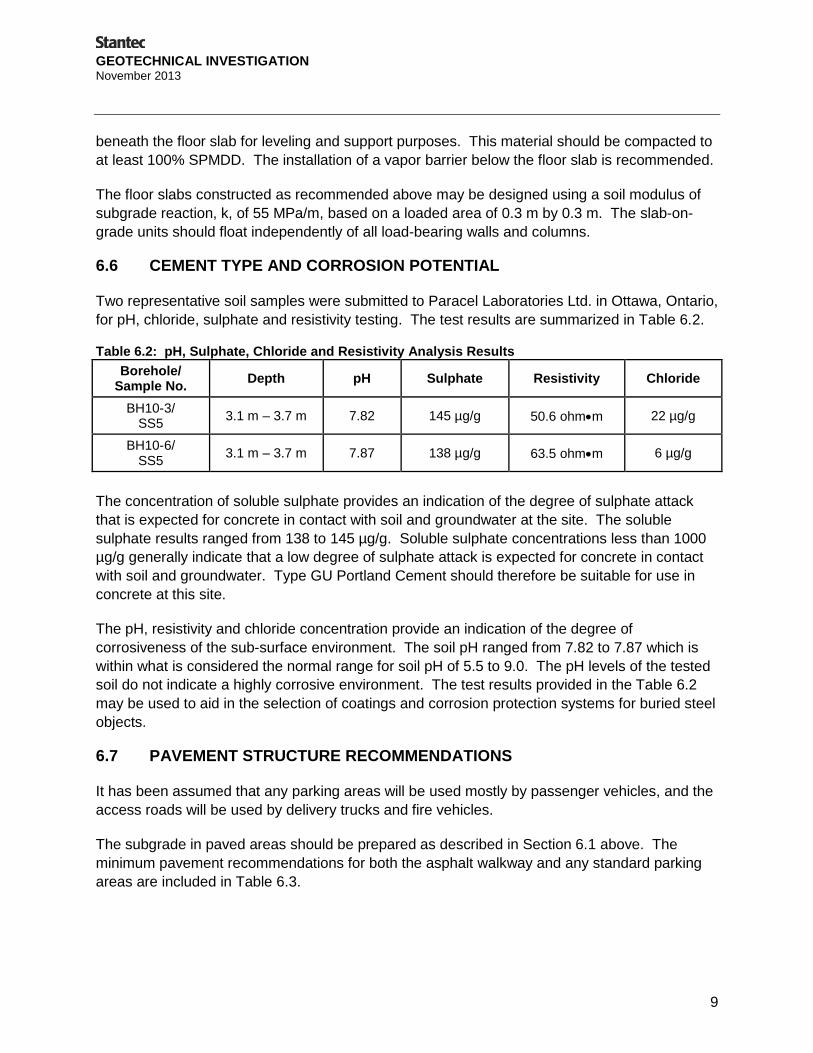
6.6 CEMENT TYPE AND CORROSION POTENTIAL
Two representative soil samples were submitted to Paracel Laboratories Ltd. in Ottawa, Ontario,
for pH, chloride, sulphate and resistivity testing. The test results are summarized in Table 6.2.
Table 6.2: pH, Sulphate, Chloride and Resistivity Analysis Results
Borehole/ Sample No.
Depth pH Sulphate Resistivity Chloride
BH10-3/ SS5
3.1 m – 3.7 m 7.82 145 µg/g 50.6 ohmm 22 µg/g
BH10-6/ SS5
3.1 m – 3.7 m 7.87 138 µg/g 63.5 ohmm 6 µg/g
The concentration of soluble sulphate provides an indication of the degree of sulphate attack
that is expected for concrete in contact with soil and groundwater at the site. The soluble
sulphate results ranged from 138 to 145 µg/g. Soluble sulphate concentrations less than 1000
µg/g generally indicate that a low degree of sulphate attack is expected for concrete in contact
with soil and groundwater. Type GU Portland Cement should therefore be suitable for use in
concrete at this site.
The pH, resistivity and chloride concentration provide an indication of the degree of
corrosiveness of the sub-surface environment. The soil pH ranged from 7.82 to 7.87 which is
within what is considered the normal range for soil pH of 5.5 to 9.0. The pH levels of the tested
soil do not indicate a highly corrosive environment. The test results provided in the Table 6.2
may be used to aid in the selection of coatings and corrosion protection systems for buried steel
objects.
6.7 PAVEMENT STRUCTURE RECOMMENDATIONS
It has been assumed that any parking areas will be used mostly by passenger vehicles, and the
access roads will be used by delivery trucks and fire vehicles.
The subgrade in paved areas should be prepared as described in Section 6.1 above. The
minimum pavement recommendations for both the asphalt walkway and any standard parking
areas are included in Table 6.3.

GEOTECHNICAL INVESTIGATION November 2013
10
Table 6.3: Recommended Pavement Design
Material Asphalt Walkway Standard Duty Parking
Area
HL-3 Asphaltic Concrete 40 mm 50 mm
Granular Base Course, OPSS Granular A 150 mm 150 mm
Granular Subbase Course, OPSS Granular B Type II 150 mm 300 mm
It is estimated that the service life prior to major rehabilitation for the above pavement structures
is 20 years provided they are properly maintained. The pavement surface and the underlying
subgrade should be graded to direct runoff water towards suitable drainage.
All granular materials should be tested and approved by a geotechnical engineer prior to
delivery to the site. Both base and subbase materials should be compacted to at least 100%
SPMDD. Asphalt should be compacted to at least 97% Marshal bulk density.
It is recommended that the lateral extent of the subbase and base layers not be terminated in a
vertical fashion immediately behind the curb line. A taper with a grade of 5 horizontal to 1
vertical is recommended in the subgrade line to minimize differential frost heave problems under
sidewalks.
6.8 SEISMIC SITE CLASSIFICATION
Liquefaction Induced Settlements
An assessment for seismic liquefaction has been carried out for this site. Seismic liquefaction is
the sudden loss in stiffness and strength of soil due to the loading effects of an earthquake.
Liquefaction can cause significant settlements and structural failure.
The analysis followed was the one set forth in the Canadian Foundation and Engineering
Manual, 2006 (CFEM). For the analysis, a magnitude 6.2 design earthquake with a Peak
Ground Acceleration of 0.42g, were assumed. Based on the SPT N for the soil, plots of Factor
of Safety against Liquefaction (FSL) with depth were developed for the site. It should be noted
that the recorded SPT ‘N’ values may be artificially low due to the drilling method which would
result in conservative estimates of the FSL. The FSL profiles for the site are included in
Appendix F of this report.
Our analysis indicates that the site soil is not considered susceptible to liquefaction. The FSL
result from boreholes BH10-02 and BH10-07 indicated values less than 1, however these
results are attributed to low ‘N’ values caused by the drilling activities.
Seismic Site Classification
As outlined in the 2006 Ontario Building Code buildings, their foundations must be designed to
resist a minimum earthquake force. In accordance with Table 4.1.8.4.A of the 2006 Ontario
Building Code the seismic site response for the site is Class D – Stiff Soil. The site class is
based on the Average Standard Penetration Resistance shown in Table 6.4.

GEOTECHNICAL INVESTIGATION November 2013
11
Table 6.4: Parameters for Seismic Site Classification
Depth Soil N60 Value
3 m to 6 m Till 10
6 m to 9 m Till 25
9 m to 33 m Bedrock 100
Design N60 45
6.9 LATERAL EARTH PRESSURES
The earth pressures recommended in Table 6.5 are based on the assumption that a permanent
horizontal back slope will be utilized behind the wall. In order to use the coefficients of
pressures for the granular materials, the granular backfill must be provided within a wedge
extending from the base of the wall at 45 degrees (or smaller) to the horizontal. If a smaller
wedge is used, the coefficients of earth pressures of the materials outside the backfill wedge
must be used for lateral pressure design calculations.
For walls that are designed to allow rotation, active earth pressure may be used for design. For
rigidly tied structures, the at rest pressure should be used for design, unless the wall can deflect
enough (approximately 0.05% of the wall height) to establish the active pressure.
Lateral earth pressures may be calculated using parameters provided in Table 6.5.
Table 6.5: Lateral Earth Pressure Parameters
Parameter Native Till OPSS Granular A OPSS Granular B Type II
Unit Weight (kN/m3) 23.0 22.8 21.2
Angle of Internal Friction, Φ 34° 35° 32°
Coefficient of Passive Earth Pressure, Kp
3.5 3.7 3.3
Coefficient of at Rest Earth Pressure, Ko
0.44 0.43 0.47
Coefficient of Active Earth Pressure, Ka
0.28 0.27 0.31
Sliding resistance can be calculated using the following unfactored friction coefficients, outlined
in Table 6.6.
Table 6.6: Unfactored Friction Coefficients
Condition Unfactored Friction Coefficient
Between Concrete and Structural Fill 0.55
Between Concrete and Native Soil 0.35
GEOTECHNICAL INVESTIGATION November 2013
12
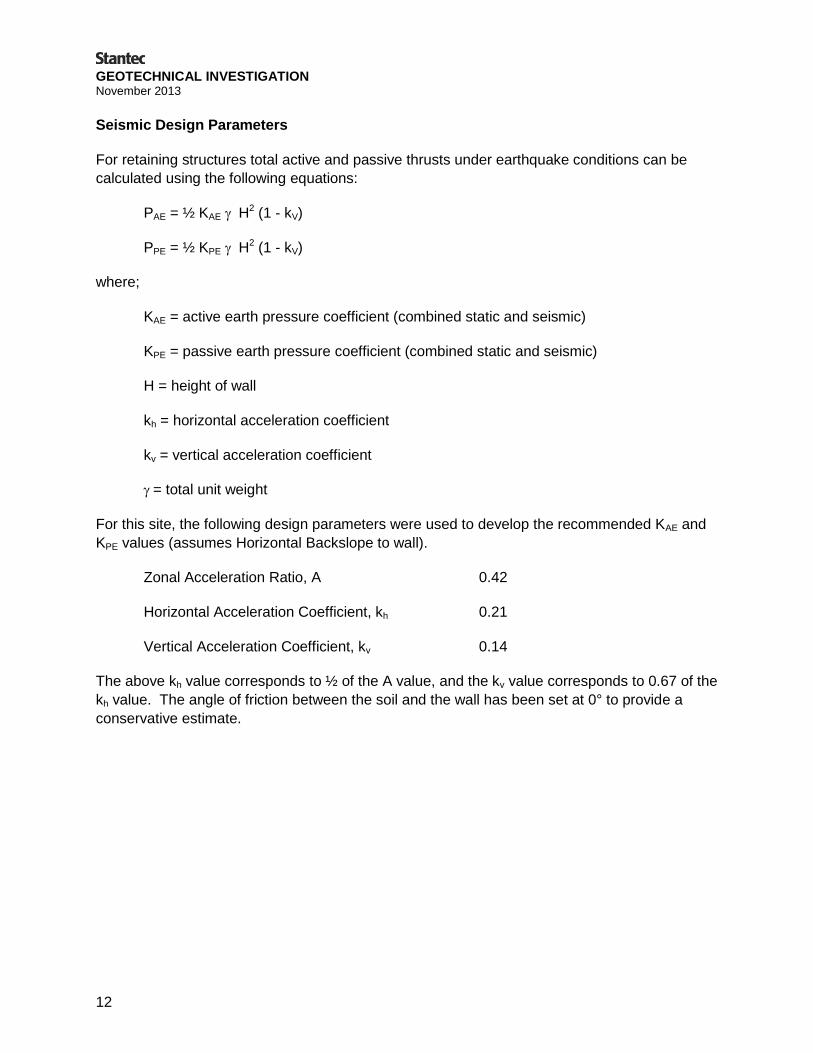
Seismic Design Parameters
For retaining structures total active and passive thrusts under earthquake conditions can be
calculated using the following equations:
PAE = ½ KAE H2 (1 - kV)
PPE = ½ KPE H2 (1 - kV)
where;
KAE = active earth pressure coefficient (combined static and seismic)
KPE = passive earth pressure coefficient (combined static and seismic)
H = height of wall
kh = horizontal acceleration coefficient
kv = vertical acceleration coefficient
= total unit weight
For this site, the following design parameters were used to develop the recommended KAE and
KPE values (assumes Horizontal Backslope to wall).
Zonal Acceleration Ratio, A 0.42
Horizontal Acceleration Coefficient, kh 0.21
Vertical Acceleration Coefficient, kv 0.14
The above kh value corresponds to ½ of the A value, and the kv value corresponds to 0.67 of the
kh value. The angle of friction between the soil and the wall has been set at 0° to provide a
conservative estimate.

GEOTECHNICAL INVESTIGATION November 2013
13
Table 6.7: Combined Coefficients of Static and Seismic Earth Pressure
Parameter
Native Till
OPSS Granular A
OPSS Granular B Type II
Bulk Unit Weight, (kN/m3) 23.0 22.8 21.2
Effective Friction Angle 34° 35° 32°
Angle of Internal Friction between wall and backfill
0 degrees 0 degrees 0 degrees
Yielding Wall
Active Earth Pressure (KAE) 0.45 0.43 0.48
Height of Application of PAE from base as a ratio of wall height (H)
0.403 0.404 0.401
Passive Earth Pressure (KPE) 3.04 3.19 2.78
Height of Application of PPE from base as a ratio of wall height (H)
0.239 0.241 0.236
If the wall is designed as non-yielding wall it could be designed with the Wood (1973) method:
= Steady state dynamic thrust
= 20 kn/m3
= Height of wall (m)
= Amplitude of harmonic base acceleration = 0.42 m/s2
= Acceleration due to gravity (m/s2) = 9.81 m/s2
= 1.1
heq = 0.63H


GEOTECHNICAL INVESTIGATION November 2013
APPENDIX A Statement of General Conditions


GEOTECHNICAL INVESTIGATION November 2013
APPENDIX B Key Plan
Borehole Location Plan on Existing Site
Borehole Location Plan on Proposed Site

T:\A
utocad\D
raw
ings\P
roject D
raw
ings\2013\163808203\163808203-3.dw
g P
RIN
TE
D: N
ov 26, 2013
163808203
3
1 : 250
13/11/26
GBB
PROPOSED BUILDING PLAN
GEOTECHNICAL INVESTIGATION
17 ROBINSION AVENUE, OTTAWA, ONTARIO
ROBINSON PARK DEVELOPMENT CORP.
© 2012
PROPERTY BOUNDARY
EXISTING MONITORING
WELL BY OTHERS
BOREHOLE
LEGEND:
SITE PLAN PREPEARD
BY M. DAVID BLAKELEY
ARCHITECT INC.
SHEET No.: A-1
REVISED: JUNE 2012
REFERENCE:
MONITORING WELL
BENCHMARK (TOP OF
FIRE HYDRANT
SPINDLE)
GEODETIC EL.=62.113 m

GEOTECHNICAL INVESTIGATION November 2013
APPENDIX C Symbols and Terms Used on Borehole and Test Pit Records
Borehole Records
Field Rock Core Log


GEOTECHNICAL INVESTIGATION November 2013
APPENDIX D Laboratory Test Results


GEOTECHNICAL INVESTIGATION November 2013
APPENDIX E Bedrock Core Photos

Bedrock Core Photos Project No. 163808203
Page 1
Photo No. 1: BH10-04 9.60m – 11.58m
Photo No. 2: BH10-04 9.60m – 11.58m

GEOTECHNICAL INVESTIGATION November 2013
APPENDIX F Factor of Safety Against Liquefaction (FSL) with Depth Profile