Geotechnical Investigation - Industrial Site Readiness ...
27
GEOTECHNICAL INVESTIGATION FOR PROPOSED INDUSTRIAL SITE READINESS – KALLA LOT BESSEMER, MICHIGAN JULY 15, 2020 CEC PROJECT NO. GD‐200149
Transcript of Geotechnical Investigation - Industrial Site Readiness ...

GEOTECHNICAL INVESTIGATION
FOR
PROPOSED INDUSTRIAL SITE READINESS – KALLA LOT
BESSEMER, MICHIGAN
JULY 15, 2020
CEC PROJECT NO. GD‐200149

GEOTECHNICAL INVESTIGATION
FOR
PROPOSED INDUSTRIAL SITE READINESS – KALLA LOT
BESSEMER, MICHIGAN
JULY 15, 2020
CEC PROJECT NO. GD‐200149
Prepared By: COLEMAN ENGINEERING COMPANY 200 E. Ayer Street Ironwood, MI 49938
July 15, 2020 Ms. Charly Loper, City Manager City of Bessemer 411 S. Sophie Street Bessemer, MI 49911 Re: Geotechnical Investigation Proposed Industrial Site Readiness – Kalla Lot Bessemer, Michigan Dear Ms. Loper: Coleman Engineering Company (CEC) has completed the geotechnical investigation for the above referenced project. Enclosed are two (2) copies of a Geotechnical Report that includes a summary of the field and laboratory activities associated with the investigation. We appreciate the opportunity to serve you. If you have any questions about our report, please feel free to call me in our Ironwood office at (906) 932‐5048. Sincerely, COLEMAN ENGINEERING COMPANY
Garth C. Stengard, P.E. Geotechnical Engineering Manager GCS/ks Enclosure CEC Project No. GD‐200149

Coleman Engineering Company 4 Geotechnical Investigation Report
Proposed Industrial Site Readiness‐Kalla Lot July 15, 2020
TABLE OF CONTENTS
PAGE #
I. INTRODUCTION ............................................................................................... 1
II. FIELD PROCEDURES ......................................................................................... 1
III. LABORATORY PROCEDURES ............................................................................ 1
. IV. SITE CONDITIONS ............................................................................................. 2
V. ANALYSIS AND RECOMMENDATIONS ............................................................. 2
Site Preparation and Grading .......................................................................... 2
Shallow Foundations ....................................................................................... 4
Floor Slabs ....................................................................................................... 4
Pavement Areas .............................................................................................. 4
Lateral Loads ................................................................................................... 5
Underground Utility Construction ................................................................... 6
Exterior Concrete Flatwork ............................................................................. 7
Inspection and Testing .................................................................................... 7
Construction Considerations ........................................................................... 8
VI. LIMITATIONS OF SUBSURFACE EXPLORATION ................................................ 9
APPENDIX
APPENDIX A. LOCATION MAPS ‐ Project Location Map ‐ Boring Location Maps
APPENDIX B. CLASSIFICATION OF SOILS FOR ENGINEERING PURPOSES (UNIFIED SOIL CLASSIFICATION SYSTEM) APPENDIX C. SOIL EXPLORATION‐GENERAL NOTES AND LEGEND APPENDIX D. BORING LOGS

Coleman Engineering Company 1 Geotechnical Investigation Report
Proposed Industrial Site Readiness‐Kalla Lot July 15, 2020
I. INTRODUCTION
The City of Bessemer is investigating their industrial areas for new building sites. This investigation
covers recommendations for the Kalla Lot. The site is located in the northwest quadrant of Eli
Avenue and Kalla Road in Bessemer, Michigan. Industrial buildings are typically one to two story,
slab‐on‐grade structures. Wall and column loads were not known at the time of the report. The
purpose of this report is to document the results of the field investigation and to provide
recommendations/guidance for soil bearing capacity, settlement mitigation, groundwater
management, pavement design, earthwork quality assurance/control (QA/QC) and other
geotechnical considerations.
II. FIELD PROCEDURES
The site was evaluated with a total of three (3) soil borings designated as B‐10 through B‐12. The
borings were advanced with a Diedrich D‐120 all‐terrain mounted drill unit present at the site on
June 19, 2020. Drilling was completed using 4 ¼‐inch I.D. hollow‐stem augers (HSA).
The HSA act as continuously‐advancing steel casing that prevents the borehole walls from
collapsing in above the depths to be tested/sampled. Sampling tools are lowered inside the augers
for testing into undisturbed soils ahead of the tip of the augers.
Drilling and field sampling of soils were performed in accordance with American Society for Testing
and Materials (ASTM) D‐1586, "Penetration Test and Split Barrel Sampling of Soils" with a 2‐inch
O.D. split spoon. Twenty‐one (21) such samples were obtained.
A field log was prepared for each boring during exploration, which contained the work method,
standard penetration test (SPT) data, samples recovered and the indication of the presence of
various soil types. The field logs were submitted to Coleman Engineering Company’s (CEC)
laboratory along with the soil samples for evaluation of the subsurface information and preparation
of the final boring logs.
The boring locations were selected by the City of Bessemer and established in the field by the CEC
drill crew. Ground surface elevations at the boring locations were provided by the CEC Survey
Crew. The general project location and boring location maps are presented in Appendix A.
III. LABORATORY PROCEDURES
All field soil samples collected were visually classified in accordance with ASTM D‐2488,

Coleman Engineering Company 2 Geotechnical Investigation Report
Proposed Industrial Site Readiness‐Kalla Lot July 15, 2020
“Description and Identification of Soils (Visual‐Manual Procedure).” Because of the relative
uniformity and density of the subsurface conditions encountered and extensive past experience
with local subsurface conditions, additional laboratory testing was deemed unnecessary.
The final logs contain both factual and interpretive information. It should be emphasized that the
recommendations are based only on the final boring logs. On the final logs, horizontal lines
designating the interface between differing materials encountered represent approximate
boundaries. The transition between soil strata is typically gradual.
IV. SITE CONDITIONS The site is sloping downward to northeast with corresponding elevations at the boring locations
ranging from +1448.51 to 1452.65.
The borings encountered interbedded layers of glacial sandy silt (ML), silty sand (SM) and poorly
graded sand (SP) to the maximum depths explored. The native soils were generally in a very loose
to medium dense condition. For a more detailed soil description see the individual soil boring logs
in Appendix D.
Measureable groundwater was encountered in the borings at depths ranging from about 6.0 to 6.5
feet below the existing ground surface corresponding to elevations +1442.51 and 1445.45. The
groundwater levels may fluctuate several feet seasonally, owing to rainfall, snowmelt, surface
runoff, and other factors.
V. ANALYSIS AND RECOMMENDATIONS
Our analysis and recommendations related to the geotechnical aspects of the proposed project
include:
Site Preparation and Grading
We recommend that topsoil and any deleterious materials be stripped/excavated from within the
building footprint, building appurtenances, sidewalks, pavements and utilities to a lateral distance
equal to the depth of removal (1 foot horizontal to 1 foot vertical) and replaced with engineered fill
as defined below.
Excavations deeper than about 6.0 feet at this site will encounter groundwater. It is anticipated
that groundwater will flow unpredictably into excavations at this depth. Any excavation that is

Coleman Engineering Company 3 Geotechnical Investigation Report
Proposed Industrial Site Readiness‐Kalla Lot July 15, 2020
anticipated to intersect the water table will require dewatering.
Dewatering will likely need to be accomplished with a combination of a perimeter dewatering
system or deep well system. Dewatering operations will need to be sufficient to allow fill
placement and foundation construction activities to take place in dry conditions. Dewatering
should lower the groundwater surface to at least 2 feet below the bottom of all excavations to
avoid upward flow gradients that could destabilize the base of the excavation and so that any
required engineered fill placement can take place in “dry” conditions.
Dewatering systems are typically installed in the field by contractors using “trial and error”
methods. The contractor may need to adjust the system a number of times until finding a
combination of pump size and well spacing best matched to the local conditions. In any case,
prospective contractors will need to evaluate dewatering methods and discharge permitting
appropriate to this project for themselves. Dewatering operations will need to be maintained 24
hours a day, 7 days a week, until all construction activities taking place below the groundwater
surface are complete. Dewatering activities may require discharge permitting.
All subgrades exposed after stripping/excavation should be evaluated by a geotechnical engineer or
person under the direction of a geotechnical engineer. The evaluation should include shallow hand
auger borings and/or dynamic cone penetrometer tests to determine if the native subgrade soils
are similar to those encountered in the soil borings and suitable for support of fill and structure
loads. All native subgrade exposed after stripping/excavation should be compacted to a minimum
of ninety percent (90%) of modified Proctor (ASTM D‐1557) maximum dry density prior to any
backfilling or placing foundations.
Excavation equipment operating on an exposed subgrade that is within 12 inches of the
groundwater table may cause significant disturbance to bearing conditions of the soil. Therefore,
we recommend that all excavation/stripping be accomplished using a tracked backhoe. All
construction traffic needs to be eliminated from traveling across the exposed subgrade until
foundations have been constructed and the interior foundation walls have been backfilled.
Engineered fill should consist of sand and/or gravel with less than about ten percent (10%) by
weight of fines passing the No. 200 sieve with a maximum rock size of about 4 inches. A soil
meeting Michigan Department of Transportation (MDOT) specifications for Class II or IIA sand
would be acceptable for use as engineered fill. Fill shall be placed in lifts not exceeding about 12
inches in loose thickness compacted to a minimum of ninety‐five percent (95%) of modified Proctor
(ASTM D‐1557) maximum dry density. The on‐site poorly graded sand (SP) may be acceptable for
use as engineered fill pending the results of laboratory testing.

Coleman Engineering Company 4 Geotechnical Investigation Report
Proposed Industrial Site Readiness‐Kalla Lot July 15, 2020
Shallow Foundations
We recommend that any proposed buildings at this site be supported on conventional spread
footings supported on native sand and/or compacted engineered fill. Foundations so supported can
be proportioned for a net allowable soil bearing pressure of up to 2,000 pounds per square foot.
The net allowable soil bearing pressure refers to that pressure in excess of the final overburden
pressure. The recommended net allowable bearing pressure can be increased by one‐third for
short‐term transient type live loadings. For the recommended design soil bearing pressure, we
estimate a total settlement of less than ¾ inch. Differential settlement is expected to approach
fifty to seventy‐five percent (50 to 75%) of the total settlement for similarly sized structures and
loads.
All perimeter footings should extend to a minimum depth of 42 inches or below frost depth, as
defined by local building codes/practice. Interior footings in heated areas can be located
immediately below the floor slab. All continuous wall footings should have a minimum width of 16
inches. An adequate thickness of insulation is recommended on the inside face of all
footing/foundation walls exposed to cold weather. All isolated exterior footings should extend a
minimum depth of 60 inches or below frost depth, as defined by local building codes/practice.
Floor Slabs
As with the footings, earth supported interior floors are recommended to be constructed on native
soil or engineered fill. We recommend that the base of the slab be separated from the subgrade
with an appropriate vapor barrier (Visqueen or similar). If the structure cannot accommodate
curling or shrinkage of the floor, industry standards often recommend burying the vapor barrier
beneath a minimum of 4 inches of free draining sand. However, we would caution that this
practice risks trapping water between the slab and vapor barrier. We recommend contacting the
floor covering manufacturer for placement of vapor barrier. If required, earth supported floor slabs
can be designed using a modulus of subgrade reaction of 225 pounds per square inch per inch (pci)
of deflection.
Pavement Areas We recommend that any deleterious materials be stripped/excavated from beneath the proposed
pavement area as defined in the “Site Preparation” section. Excavation should extend to a depth to
accommodate the pavement section defined below. Where fill is required, we recommend it be
compacted to at least ninety‐five percent (95%) modified Proctor density (ASTM D‐1557). Any
natural soils within 2 feet of top of subgrade should be scarified to a depth of at least 6 inches

Coleman Engineering Company 5 Geotechnical Investigation Report
Proposed Industrial Site Readiness‐Kalla Lot July 15, 2020
before placing fill or pavements and then surface compacted. This is intended to disrupt any near
surface seams of saturated sands, which could later result in weak spots or frost boils in the
subgrade.
If there are areas which cannot be compacted, we recommend that the unstable materials be
subexcavated to a depth of at least 2 feet and be replaced by materials which can be compacted.
Ideally, the fill should be similar to the existing soils. Subsequent fill should be similarly moistened
and compacted.
Prior to placing fill, we advise “proof‐rolling” the subgrade with a rubber‐tire roller or heavy truck.
The rolling should be observed by a geotechnical engineer or a field technician under the direction
of a geotechnical engineer. Soft or spongy areas should be sub‐cut, replaced and compacted as
directed. The surface of the subgrade should be graded so as not to create low areas where water
will collect.
Flexible Bituminous Pavement
For the assumptions of a firm subgrade and light traffic volumes, we recommend a pavement
section of 3 inches of MDOT bituminous concrete surface course and 8 inches of MDOT 22A
aggregate base course for car and light truck areas. For heavy truck areas, we recommend
increasing the bituminous concrete thickness to 4 inches. The aggregate base course should be
compacted to ninety‐five percent (95%) modified Proctor density; the bituminous concrete should
be compacted to ninety‐two percent (92%) Theoretical Maximum Density. Density tests should be
conducted to confirm that these densities are achieved.
Rigid Concrete Pavement
For concrete pavements, we recommend a minimum pavement section of six inches of reinforced
Portland cement concrete and eight inches of MDOT Class IIA sand for uniform load support. The
sand base should be compacted to ninety‐five percent (95%) modified Proctor density. Density
tests should be conducted to confirm that these densities are achieved.
Paved areas should be inspected frequently, particularly in the fall, and cracks sealed as soon as
possible.
Lateral Loads We recommend using the following equivalent fluid pressures and a triangular‐shaped pressure
distribution for the design of any walls resisting lateral loads from soil backfill:

Coleman Engineering Company 6 Geotechnical Investigation Report
Proposed Industrial Site Readiness‐Kalla Lot July 15, 2020
WALL TYPE
EQUIVALENT ACTIVE FLUID PRESSURE
EQUIVALENT PASSIVE FLUID
PRESSURE
Restrained at top
60 pcf 300 pcf
Free to rotate at top
40 pcf 300 pcf
Backfill within 5 lateral feet of the back of the walls should consist of MDOT Class II Sand. The
backfill should be compacted to at least ninety‐five percent (95%) of modified Proctor maximum
dry density. Relatively light manually‐propelled compactors should be used within five (5) feet of
walls. Compactors used beyond five (5) feet should be limited in weight to 3,000 lbs.
A minimum 4‐inch diameter perforated flexible drainage pipe (ADS green stripe or similar) should
be located behind, parallel to, the wall, above the water table. The pipe should be embedded in
washed concrete aggregate wrapped with filter fabric (Mirafi 140N or similar). The pipe should be
routed to gravity discharge away from any structure.
External loads on the back of walls have not been taken into account in our recommendations.
Surcharge loads imposed by vehicle parking, construction equipment and material storage should
be considered during structural design.
Underground Utility Construction
Soil types encountered during utility installation will likely be native sand. Based on the borings,
the native sands encountered at depth are generally suitable for utility support provided the
excavations are adequately dewatered. If over‐excavation is required, we recommend that the
unsuitable soils be removed a lateral distance equal to the depth of removal (1 foot horizontal to
1 foot vertical) below the utility line and replaced with engineered fill. In the event that unstable
soils are encountered, it may be necessary to undercut these soils 1 to 3 feet (depth to be
determined by field observation) and replace them with engineered fill as outlined in the site
preparation and grading section in order to provide a stable work surface. Engineered fill below
utility lines should be compacted to a minimum of ninety percent (90%) modified Proctor density
(ASTM D‐1557).
All trench backfill above utility lines should be compacted to a minimum of ninety percent (90%) of
modified Proctor maximum dry density. Trench backfill should be placed in lifts not exceeding
about 12 inches in loose thickness. Excavated soils are recommended for trench backfill above the
pipe bedding material if they are at or can be brought, with reasonable effort, to the moisture
content optimum for compaction as defined by the modified Proctor test (ASTM D‐1557). Also, the

Coleman Engineering Company 7 Geotechnical Investigation Report
Proposed Industrial Site Readiness‐Kalla Lot July 15, 2020
excavated soils shall be free of chunks of frozen soil, organics, cobbles and boulders larger than
about 4 inches and other deleterious materials. If this is not the case, we recommend that all
excavations be backfilled with a soil recommended by a geotechnical engineer familiar with site
subsurface conditions. Backfill to at least 12 inches above the pipe crown (pipe bedding) should
consist of MDOT Class II sand.
Trench spoil, heavy equipment and any type of vibrating machinery should not be permitted within
a lateral distance from the top of the trench/excavation equal to 0.5 times the depth of the
trench/excavation.
Caving of trench sidewalls and soils at the site should be expected to occur at any depth and
without warning. All utility trenches should be cut back or braced as required to provide safe
trench working conditions. Trench safety is the responsibility of the utility contractor.
Exterior Concrete Flatwork
We recommend that exterior concrete flatwork be supported on a minimum of 12 inches of
engineered backfill as defined in the “Site Preparation and Grading” section compacted to a
minimum of ninety‐five percent (95%) of modified Proctor maximum dry density.
We recommend that concrete entrance stoops be supported on frost‐depth footings to prevent
frost heave from negatively impacting door operation. Walkways leading to the entrance flatwork,
as well as other exterior concrete flatwork, should be supported on a minimum of 12 inches of
engineered fill placed over a firm subgrade. Exterior flatwork should be pitched to drain away from
the building.
Inspection and Testing
A qualified testing laboratory should be retained throughout the course of earthwork operations
for testing and documentation of compliance with the recommendations of this report and related
project specifications. As a guide, the following compaction testing schedule is recommended:
Area or Material To Be Tested
Recommended Minimum Testing Frequency
Native Subgrades 1 test per 2,500 sq. ft.
Engineered Fill 1 test per 2,500 sq. ft. per lift
Wall Footings 1 test per 25 lineal feet
Utility Trenches 1 test per 50 lineal feet per lift

Coleman Engineering Company 8 Geotechnical Investigation Report
Proposed Industrial Site Readiness‐Kalla Lot July 15, 2020
Construction Considerations We anticipate that the sidewalls of excavations to depths greater than 4 feet below surrounding
grades will cave to 1 vertical to 1.5 horizontal or flatter. Excavation spoil, heavy equipment and any
type of vibrating machinery should not be permitted within a lateral distance from the top of the
excavation to 0.5 times the depth of the excavation. Excavation safety is the excavation
contractor's responsibility.
Dewatering systems are typically installed in the field by contractors using “trial and error”
methods. The contractor may need to adjust the system a number of times until finding a
combination of pump size and well spacing best matched to the local conditions. In any case,
prospective contractors will need to evaluate dewatering methods appropriate to this project for
themselves.
Excavation equipment operating on an exposed subgrade that is within 12 inches of the
groundwater may cause significant disturbance to bearing conditions of the soil. Therefore, we
recommend that all excavation be accomplished using a tracked backhoe. All construction traffic
needs to be eliminated from traveling across the exposed subgrade until foundations have been
constructed and the interior foundation walls have been backfilled. Footing excavations should be
performed with a smooth bucket excavator to minimize disturbance to excavation bottoms.
During construction, adequate provision should be made for proper drainage, so as to prevent
erosion and possible damage to this site and adjacent property. Temporary cut slopes during
construction above the water table should not exceed about 2:1 (horizontal:vertical). Post‐
construction finished slopes above the water table should not exceed about 3:1
(horizontal:vertical).

Coleman Engineering Company 9 Geotechnical Investigation Report
Proposed Industrial Site Readiness‐Kalla Lot July 15, 2020
VI. LIMITATIONS OF SUBSURFACE EXPLORATION Services performed by Coleman Engineering Company as part of this investigation have been
conducted in a manner consistent with that level of care and skill ordinarily exercised by members
of the engineering profession currently practicing under similar conditions. No other warranty,
expressed or implied, is made.
Subsurface conditions between borings will probably vary from those encountered at the locations
where borings have been made. The data, interpretations and recommendations contained herein
are based solely on the information obtained from the three (3) soil borings completed for this
study.
The conclusions and recommendations contained in this report are based on the assumption that
the materials encountered in the borings represent the site conditions. If any unforeseen
difficulties or unusual conditions are encountered, Coleman Engineering Company should be
contacted immediately in order to make supplemental recommendations.
This report completes our present assignment for this project. As the design nears completion, we
recommend that you consult with us on unanticipated problems or questions regarding the design
and/or review of any plans or specifications. The work assignments for the above services are
subject to your prior approval and authorization.
OUR CONCLUSIONS AND RECOMMENDATIONS ARE PREDICATED ON OBSERVATION AND TESTING
OF THE EXCAVATION AND FOUNDATION PREPARATIONS BY QUALIFIED PERSONNEL. IT WOULD BE
LOGICAL FOR COLEMAN ENGINEERING COMPANY TO PROVIDE THAT SERVICE, SINCE WE ARE BEST
ABLE TO DETERMINE IF THE CONDITIONS ENCOUNTERED MATCH THOSE USED IN OUR ANALYSES,
TO DETERMINE IF MODIFICATIONS OF OUR RECOMMENDATIONS ARE NEEDED AND TO MAKE SUCH
MODIFICATIONS OF OUR RECOMMENDATIONS AS MAY BE NECESSARY. MODIFICATIONS OF OUR
RECOMMENDATIONS BY OTHERS RELIEVES US OF RESPONSIBILITY FOR THEM.
This report has been completed by Garth C. Stengard, a registered engineer in the State of Michigan.
Garth C. Stengard, P.E. Geotechnical Engineer Registration #: 6201050531

APPENDIX A
PROJECT LOCATION MAPS Project Location Map
Boring Location Maps


APPENDIX B
CLASSIFICATION OF SOILS FOR ENGINEERING PURPOSES (UNIFIED SOIL CLASSIFICATION SYSTEM)

COLEMAN ENGINEERING COMPANY 635 Circle Drive
Iron Mountain, Michigan 49801
CLASSIFICATION OF SOILS FOR ENGINEERING PURPOSES ASTM Designation: D-2487 – 83
(Based on Unified Soil Classification System)
Criteria for Assigning Group Symbols and Group Names Using Laboratory TestsA Soil Classification
Group Group NameB Symbol
Coarse-Grained Soils More than 50 % retained on No. 200 sieve
Gravels More than 50 % of coarse fraction retained on No. 4 sieve
Clean Gravels Less than 5 % finesC
Cu > 4 and 1 < Cc < 3 E GW Well-graded gravel F
Cu < 4 and/or 1 > Cc > 3E GP Poorly graded gravelF
Gravels with Fines more than 12 % finesC
Fines classify as ML or MH GM Silty gravelF.G.H.
Fines classify as CL or CH GC Clayey gravelF.G.H.
Sands 50 % or more of coarse fraction passes No. 4 sieve
Clean Sands Less than 5 % finesD
Cu > 6 and 1 < Cc < 3E SW Well-graded sand
Cu < 6 and/or 1 > Cc > 3E SP Poorly graded sand l
Sands with Fines More than 12 % finesD
Fines classify as ML or MH SM Silty sandG.H.J.
Fines classify as CL or CH SC Clayey sandG.H.I.
Fine-Grained Soils 50 % or more passes the No. 200 sieve
Silts and Clays Liquid limit less than 50
inorganic Pl > 7 and plots on or above “A” lineJ CL Lean clayK.L.M.
Pl < 4 or plots below “A” lineJ ML SiltK.L.M.
organic Liquid limit – oven dried < 0.75 OL Organic clayK.L.M.N.
Liquid limit – not dried Organic siltK.L.M.O.
Silts and Clays Liquid limit 50 or more
inorganic Pl plots on or above “A” line CH Fat clayK.L.M.
Pl plots below “A” line MH Elastic siltK.L.M.
organic Liquid limit – oven dried < 0.75 OH Organic clayK.L.M.P.
Liquid limit – not dried
Organic siltK.L.M.Q.
Highly organic soils Primarily organic matter, dark in color, and organic odor PT Peat
A Based on the material passing the 3-in. (75-mm) sieve. B If field sample contained cobbles or boulders, or both, add “with cobbles or boulders, or both” to group name. C Gravels with 5 to 12 % fines require dual symbols: GW-GM well-graded gravel with silt GW-GC well-graded gravel with clay GP-GM poorly graded gravel with silt GP-GC poorly graded gravel with clay D Sands with 5 to 12 % fines require dual symbols: SW-SM well-graded sand with silt SW-SC well-graded sand with clay SP-SM poorly graded sand with silt SP-SC poorly graded sand with clay
E Cu = D60/D10 (D30)
2 L If soil contains > 30 % plus No. 200, predominantly sand, add “sandy” to group name. M If soil contains > 30 % plus No. 200, predominately gravel, add “gravelly” to group name. N Pl > 4 and plots on or above “A” line. O Pl < 4 or plots below “A” line. P Pl plots on or above “A” line. Q Pl plots below “A” line.
D10 x D60 F If soils contains > 15 % sand, add “with sand” to group name. G If fines classify as CL-ML, use dual symbol GC-GM, or SC-SM. H If fines are organic, add “with organic fines” to group name. I If soil contains > 15 % gravel, add “with gravel” to group name. J If Atterberg limits plot in hatched area, soil is a CL-ML, silty clay. K If soil contains 15 to 29 % plus No. 200, add “with sand” or “with gravel”, whichever is predominant.

APPENDIX C
SOIL EXPLORATION‐GENERAL NOTES AND LEGEND


APPENDIX D
BORING LOGS

1.2
1.2
1.0
1.0
1.2
1.0
2-6-3
4-5-5
5-8-5
2-1-2
2-2-3
3-3-4
(9)
(10)
(13)
(3)
(5)
(7)
1
2
3
4
5
6
(SM) SILTY SAND, brown, fine, with gravel, from0.0' to ± 2.0', moist, loose
...trace clay from ± 4.5' to ± 7.0', medium dense
...wet, very loose
(Glacial Outwash) ± 9.5'(SP) POORLY GRADED SAND, brown, fine tomedium, some silt, wet, loose
...fine
4-1/4" Hollow Stem Auger2" SPT Sampling140# wt., 30" dropAuto Hammer
Driller's note: Samples wet 6.0' to21.5'
DRILLING METHOD:
D. Edlebeck
hours
(tsf)
21.5BORING DEPTH:
JOB NO.:
B-10
HOLE CLOSURE:
CLIENT:
Kalla Lot - 46.468798656° N, -90.075366730 (See soil boring location drawing)
-3ST-3" Shelby Tube
(tsf)-4
-2ST-2" Shelby TubeBORING NO.:
6.0
COMMENTS
0
1
2
3
4
5
6
7
8
9
10
11
12
13
14
15
16
17
18
19
20
200149.GPJ
BORING NO.:
+4
6.0
WA
TE
R T
AB
LE
OF
DRILL CREW:
7/10/20
-2SS-2" Split Spoon after drilling
NU
MB
ER
Industrial Site Readiness
RIG TYPE:
DATE COMPLETED:
1
-AS-Auger Sample while drilling
Soil Cuttings
-PS-Piston Tube
DE
PT
H (
FT
)
RE
CO
VE
RY
2
a
qu
BORING LOCATION:
1452.7
1447.7
1442.7
1437.7
1432.7
BL
OW
S/6
"(N
)
TEST RESULTS
SP
T V
AL
UE
S
EL
EV
. (F
T)
LE
GE
ND
-3SS-3" Split Spoon
Diedrich D-120 ATV
6.0
(tsf)
after
-RC-Rock-Core
SAMPLE
REVIEWED BY:
B-10
-MC-Macrocore
C. Reidner / W. Lake
DATE STARTED:
Telephone: (906)-774-3440 Fax: (906)-774-7776
COLEMAN ENGINEERING COMPANY635 CIRCLE DRIVE
IRON MOUNTAIN, MICHIGAN 49801
TLLPL
CO
NT
EN
T (
%)
DATE:
PROJECT:
4-1/4" Hollow Stem Auger
MO
IST
UR
E
-200
City of Bessemer
6.0-BS-Bag Sample
SOIL DESCRIPTION
1452.65 +/-ELEV.:
6/19/20 6/19/20
q
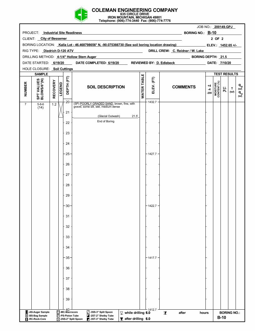
1.25-8-6(14)
7 (SP) POORLY GRADED SAND, brown, fine, withgravel, some silt, wet, medium dense
(Glacial Outwash) 21.5'
End of Boring
DRILLING METHOD:
D. Edlebeck
hours
(tsf)
21.5BORING DEPTH:
JOB NO.:
B-10
HOLE CLOSURE:
CLIENT:
Kalla Lot - 46.468798656° N, -90.075366730 (See soil boring location drawing)
-3ST-3" Shelby Tube
(tsf)-4
-2ST-2" Shelby TubeBORING NO.:
6.0
COMMENTS
20
21
22
23
24
25
26
27
28
29
30
31
32
33
34
35
36
37
38
39
40
200149.GPJ
BORING NO.:
+4
6.0
WA
TE
R T
AB
LE
OF
DRILL CREW:
7/10/20
-2SS-2" Split Spoon after drilling
NU
MB
ER
Industrial Site Readiness
RIG TYPE:
DATE COMPLETED:
2
-AS-Auger Sample while drilling
Soil Cuttings
-PS-Piston Tube
DE
PT
H (
FT
)
RE
CO
VE
RY
2
a
qu
BORING LOCATION:
1432.7
1427.7
1422.7
1417.7
1412.7
BL
OW
S/6
"(N
)
TEST RESULTS
SP
T V
AL
UE
S
EL
EV
. (F
T)
LE
GE
ND
-3SS-3" Split Spoon
Diedrich D-120 ATV
6.0
(tsf)
after
-RC-Rock-Core
SAMPLE
REVIEWED BY:
B-10
-MC-Macrocore
C. Reidner / W. Lake
DATE STARTED:
Telephone: (906)-774-3440 Fax: (906)-774-7776
COLEMAN ENGINEERING COMPANY635 CIRCLE DRIVE
IRON MOUNTAIN, MICHIGAN 49801
TLLPL
CO
NT
EN
T (
%)
DATE:
PROJECT:
4-1/4" Hollow Stem Auger
MO
IST
UR
E
-200
City of Bessemer
6.0-BS-Bag Sample
SOIL DESCRIPTION
1452.65 +/-ELEV.:
6/19/20 6/19/20
q

1.0
1.5
1.5
1.5
1.5
1.5
1-2-2
3-4-3
2-2-2
3-3-4
WOH/1'-1
2-2-3
(4)
(7)
(4)
(7)
(-)
(5)
1
2
3
4
5
6
TOPSOIL0.2'
(ML) SANDY SILT, brown, non-plastic, moist, veryloose
...slightly plastic, loose
...moderately plastic, wet, very loose
(Glacial Outwash) ± 7.0'(SM) SILTY SAND, brown, fine, wet, loose
...fine to medium, very loose
(Glacial Outwash) ± 13.0'(SP) POORLY GRADED SAND, brown, fine tomedium, some silt, wet, loose
(Glacial Outwash) ± 18.0'(SM) SILTY SAND WITH GRAVEL, brown, fine tocoarse, wet, medium dense
4-1/4" Hollow Stem Auger2" SPT Sampling140# wt., 30" dropAuto Hammer
Driller's note: Samples wet 6.0' to21.5'
DRILLING METHOD:
D. Edlebeck
hours
(tsf)
21.5BORING DEPTH:
JOB NO.:
B-11
HOLE CLOSURE:
CLIENT:
Kalla Lot - 46.468895900° N, -90.074608707 (See soil boring location drawing)
-3ST-3" Shelby Tube
(tsf)-4
-2ST-2" Shelby TubeBORING NO.:
6.0
COMMENTS
0
1
2
3
4
5
6
7
8
9
10
11
12
13
14
15
16
17
18
19
20
200149.GPJ
BORING NO.:
+4
6.0
WA
TE
R T
AB
LE
OF
DRILL CREW:
7/10/20
-2SS-2" Split Spoon after drilling
NU
MB
ER
Industrial Site Readiness
RIG TYPE:
DATE COMPLETED:
1
-AS-Auger Sample while drilling
Soil Cuttings
-PS-Piston Tube
DE
PT
H (
FT
)
RE
CO
VE
RY
2
a
qu
BORING LOCATION:
1448.5
1443.5
1438.5
1433.5
1428.5
BL
OW
S/6
"(N
)
TEST RESULTS
SP
T V
AL
UE
S
EL
EV
. (F
T)
LE
GE
ND
-3SS-3" Split Spoon
Diedrich D-120 ATV
6.0
(tsf)
after
-RC-Rock-Core
SAMPLE
REVIEWED BY:
B-11
-MC-Macrocore
C. Reidner / W. Lake
DATE STARTED:
Telephone: (906)-774-3440 Fax: (906)-774-7776
COLEMAN ENGINEERING COMPANY635 CIRCLE DRIVE
IRON MOUNTAIN, MICHIGAN 49801
TLLPL
CO
NT
EN
T (
%)
DATE:
PROJECT:
4-1/4" Hollow Stem Auger
MO
IST
UR
E
-200
City of Bessemer
6.0-BS-Bag Sample
SOIL DESCRIPTION
1448.51 +/-ELEV.:
6/19/20 6/19/20
q

1.26-11-12(23)
7 (SM) SILTY SAND WITH GRAVEL, brown, fine tocoarse, wet, medium dense
(Glacial Outwash) 21.5'
End of Boring
DRILLING METHOD:
D. Edlebeck
hours
(tsf)
21.5BORING DEPTH:
JOB NO.:
B-11
HOLE CLOSURE:
CLIENT:
Kalla Lot - 46.468895900° N, -90.074608707 (See soil boring location drawing)
-3ST-3" Shelby Tube
(tsf)-4
-2ST-2" Shelby TubeBORING NO.:
6.0
COMMENTS
20
21
22
23
24
25
26
27
28
29
30
31
32
33
34
35
36
37
38
39
40
200149.GPJ
BORING NO.:
+4
6.0
WA
TE
R T
AB
LE
OF
DRILL CREW:
7/10/20
-2SS-2" Split Spoon after drilling
NU
MB
ER
Industrial Site Readiness
RIG TYPE:
DATE COMPLETED:
2
-AS-Auger Sample while drilling
Soil Cuttings
-PS-Piston Tube
DE
PT
H (
FT
)
RE
CO
VE
RY
2
a
qu
BORING LOCATION:
1428.5
1423.5
1418.5
1413.5
1408.5
BL
OW
S/6
"(N
)
TEST RESULTS
SP
T V
AL
UE
S
EL
EV
. (F
T)
LE
GE
ND
-3SS-3" Split Spoon
Diedrich D-120 ATV
6.0
(tsf)
after
-RC-Rock-Core
SAMPLE
REVIEWED BY:
B-11
-MC-Macrocore
C. Reidner / W. Lake
DATE STARTED:
Telephone: (906)-774-3440 Fax: (906)-774-7776
COLEMAN ENGINEERING COMPANY635 CIRCLE DRIVE
IRON MOUNTAIN, MICHIGAN 49801
TLLPL
CO
NT
EN
T (
%)
DATE:
PROJECT:
4-1/4" Hollow Stem Auger
MO
IST
UR
E
-200
City of Bessemer
6.0-BS-Bag Sample
SOIL DESCRIPTION
1448.51 +/-ELEV.:
6/19/20 6/19/20
q

0.5
1.0
1.5
1.0
1.5
1.5
3-4-1
5-5-5
3-7-7
1-3-5
2-3-4
6-13-17
(5)
(10)
(14)
(8)
(7)
(30)
1
2
3
4
5
6
(SM) SILTY SAND, brown, fine, moist, loose
...with gravel from ± 2.0' to ± 4.5'
...wet, medium dense
(Glacial Outwash) ± 7.0'(SP) POORLY GRADED SAND, brown, fine tomedium, some silt, wet, loose
(Glacial Outwash) ± 9.5'(SM) SILTY SAND, brown, fine, wet, loose
(Glacial Outwash) ± 13.5'(GM) SILTY GRAVEL WITH SAND, brown, fine tocoarse, rounded to subangular, wet, medium dense
(Glacial Outwash) ± 18.0'(SP) POORLY GRADED SAND, brown, fine tomedium, trace silt, wet, medium dense
4-1/4" Hollow Stem Auger2" SPT Sampling140# wt., 30" dropAuto Hammer
Driller's note: Samples wet 6.5' to21.5'
DRILLING METHOD:
D. Edlebeck
hours
(tsf)
21.5BORING DEPTH:
JOB NO.:
B-12
HOLE CLOSURE:
CLIENT:
Kalla Lot - 46.468561711° N, -90.074472712 (See soil boring location drawing)
-3ST-3" Shelby Tube
(tsf)-4
-2ST-2" Shelby TubeBORING NO.:
6.5
COMMENTS
0
1
2
3
4
5
6
7
8
9
10
11
12
13
14
15
16
17
18
19
20
200149.GPJ
BORING NO.:
+4
6.5
WA
TE
R T
AB
LE
OF
DRILL CREW:
7/10/20
-2SS-2" Split Spoon after drilling
NU
MB
ER
Industrial Site Readiness
RIG TYPE:
DATE COMPLETED:
1
-AS-Auger Sample while drilling
Soil Cuttings
-PS-Piston Tube
DE
PT
H (
FT
)
RE
CO
VE
RY
2
a
qu
BORING LOCATION:
1452.0
1447.0
1442.0
1437.0
1432.0
BL
OW
S/6
"(N
)
TEST RESULTS
SP
T V
AL
UE
S
EL
EV
. (F
T)
LE
GE
ND
-3SS-3" Split Spoon
Diedrich D-120 ATV
6.5
(tsf)
after
-RC-Rock-Core
SAMPLE
REVIEWED BY:
B-12
-MC-Macrocore
C. Reidner / W. Lake
DATE STARTED:
Telephone: (906)-774-3440 Fax: (906)-774-7776
COLEMAN ENGINEERING COMPANY635 CIRCLE DRIVE
IRON MOUNTAIN, MICHIGAN 49801
TLLPL
CO
NT
EN
T (
%)
DATE:
PROJECT:
4-1/4" Hollow Stem Auger
MO
IST
UR
E
-200
City of Bessemer
6.5-BS-Bag Sample
SOIL DESCRIPTION
1451.95 +/-ELEV.:
6/19/20 6/19/20
q

1.56-11-12(23)
7 (SP) POORLY GRADED SAND, brown, fine tomedium, trace silt, wet, medium dense
(Glacial Outwash) 21.5'
End of Boring
DRILLING METHOD:
D. Edlebeck
hours
(tsf)
21.5BORING DEPTH:
JOB NO.:
B-12
HOLE CLOSURE:
CLIENT:
Kalla Lot - 46.468561711° N, -90.074472712 (See soil boring location drawing)
-3ST-3" Shelby Tube
(tsf)-4
-2ST-2" Shelby TubeBORING NO.:
6.5
COMMENTS
20
21
22
23
24
25
26
27
28
29
30
31
32
33
34
35
36
37
38
39
40
200149.GPJ
BORING NO.:
+4
6.5
WA
TE
R T
AB
LE
OF
DRILL CREW:
7/10/20
-2SS-2" Split Spoon after drilling
NU
MB
ER
Industrial Site Readiness
RIG TYPE:
DATE COMPLETED:
2
-AS-Auger Sample while drilling
Soil Cuttings
-PS-Piston Tube
DE
PT
H (
FT
)
RE
CO
VE
RY
2
a
qu
BORING LOCATION:
1432.0
1427.0
1422.0
1417.0
1412.0
BL
OW
S/6
"(N
)
TEST RESULTS
SP
T V
AL
UE
S
EL
EV
. (F
T)
LE
GE
ND
-3SS-3" Split Spoon
Diedrich D-120 ATV
6.5
(tsf)
after
-RC-Rock-Core
SAMPLE
REVIEWED BY:
B-12
-MC-Macrocore
C. Reidner / W. Lake
DATE STARTED:
Telephone: (906)-774-3440 Fax: (906)-774-7776
COLEMAN ENGINEERING COMPANY635 CIRCLE DRIVE
IRON MOUNTAIN, MICHIGAN 49801
TLLPL
CO
NT
EN
T (
%)
DATE:
PROJECT:
4-1/4" Hollow Stem Auger
MO
IST
UR
E
-200
City of Bessemer
6.5-BS-Bag Sample
SOIL DESCRIPTION
1451.95 +/-ELEV.:
6/19/20 6/19/20
q