GEOTECHNICAL INVESTIGATION - BLN Plan Room
59
GEOTECHNICAL INVESTIGATION ROADWAY RECONSTRUCTION CR N 500 E FROM CR E 600 N TO CR E 700 N NEWTON COUNTY, INDIANA CTL PROJECT NO.: 19050128IND PREPARED FOR: BEAM, LONGEST AND NEFF, LLC 8320 CRAIG STREET INDIANAPOLIS, INDIANA 46250 PREPARED BY: CTL ENGINEERING, INC. 1310 S. FRANKLIN ROAD INDIANAPOLIS, INDIANA 46239 JANUARY 27, 2020
Transcript of GEOTECHNICAL INVESTIGATION - BLN Plan Room

GEOTECHNICAL INVESTIGATION
ROADWAY RECONSTRUCTION CR N 500 E FROM CR E 600 N TO CR E 700 N
NEWTON COUNTY, INDIANA CTL PROJECT NO.: 19050128IND
PREPARED FOR:
BEAM, LONGEST AND NEFF, LLC 8320 CRAIG STREET
INDIANAPOLIS, INDIANA 46250
PREPARED BY:
CTL ENGINEERING, INC. 1310 S. FRANKLIN ROAD
INDIANAPOLIS, INDIANA 46239
JANUARY 27, 2020

CTL Engineering, Inc. 1310 S. Franklin Road Indianapolis, Indiana 46239 Phone: (317) 295-8650 • Fax: (317) 295-8395 www.ctleng.com Consulting Engineers – Testing – Inspection Services – Analytical
Offices: Ohio, Indiana, Kentucky, Pennsylvania, Virginia, West Virginia, India
January 27, 2020 Beam, Longest and Neff, LLC 8320 Craig Street Indianapolis, Indiana 46250 Attention: Mr. Scott Wilkinson, PE
Mr. Vance Epple, PE
Reference: Geotechnical Investigation Roadway Reconstruction
CR N 500 E from CR E 600 N to CR E 700 N Newton County, Indiana
CTL Project No.: 19050128IND Dear Mr. Wilkinson: In accordance with your authorization to proceed, CTL Engineering, Inc. has completed the geotechnical investigation on the above referenced site. The report includes the results of the field and laboratory testing, and recommendation for the proposed roadway reconstruction. Thank you for the opportunity to be of service to you on this project. If you have any questions or need further information, please contact us at (317) 295-8650. Sincerely, CTL ENGINEERING, INC. Ali Karaki, PE Principal Engineer

This summary is provided for general information only, and it should not be used as the only source for any design, estimating or bidding. Detailed recommendations are provided in the geotechnical report. The report should be used in its entirety.
EXECUTIVE SUMMARY Roadway Reconstruction
CR N 500 E from CR E 600 N to CR E 700 N Newton County, Indiana
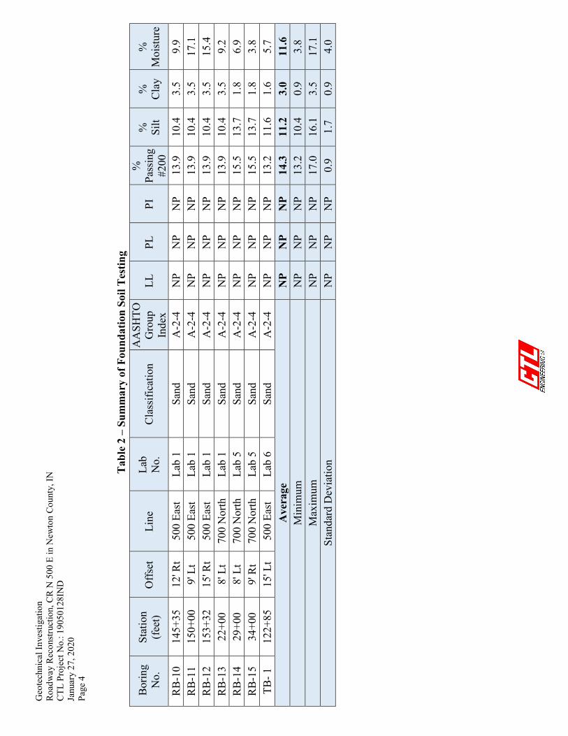
Project Description: The project involves reconstruction of CR N 500 E from CR E 600 N to CR E 700 N, and CR 700 N from approximately 415 feet west of CR 500 N to approximately 885 feet east of CR 500 N in Newton County, Indiana. The existing gravel roadways are approximately 24 feet wide with earthen shoulders. The proposed improvement consists of converting the existing gravel road to an HMA roadway with one 11-foot wide lane in each direction bordered by 2 foot wide paved and 2 foot wide aggregate shoulders. Subsurface Conditions: The test borings exhibited a surface cover consisting of 4 to 8 inches of gravel, averaging approximately 5 inches in thickness. Below the surface cover, the test borings encountered soils classified as sand of A-2-4 soil category. Samples collected from the upper the existing surficial soils (topsoil) exhibited the results summarized in Table 1 of the geotechnical report. Dark gray to black colored sand soils were encountered in all the test borings at depths ranging from 1.2 to 4.5 feet below the existing grade. Loss on ignition test performed on selected samples of this sand exhibited values ranging from 2.7 to 4.0 percent. Natural moisture content values of these foundation soils ranged from 4 to 17 percent. The pH values of the subgrade soils ranged from 7.0 to 7.6 percent. Detailed information of soil type and standard penetration values are shown in Appendices B and C and summarized in Table 2 of the geotechnical report. Pavement Considerations: The proposed HMA pavement may be designed using the soil parameters provided below in Table 4. The recommended subgrade treatment should be performed in accordance with INDOT Standard Specifications Section 207. The foundation soils should be proofrolled following INDOT Standard Specification (ISS) 203.26. Soft or wet soils not meeting the proofrolling shall be undercut up to 18 inches below the bottom of the subgrade elevation and replaced with approved material in accordance with ISS 214.03 (b). A geotextile 918.02 (c) Type 2A shall be placed at the bottom of the excavation, if needed. The subgrade treatment shall then be constructed on top of the foundation improvement. It is expected that soil improvement may be required in the widening areas. It is estimated that 15 percent of the total paved area may require foundation improvement. This estimated may fluctuate depending upon the time of construction and fluctuation in rainfall. Foundation improvement will be at the discretion of the Engineer.

Geotechnical Investigation – Executive Summary Roadway Reconstruction, CR N 500 E in Newton County, IN CTL Project No.: 19050128IND January 27, 2020 Page 2
This summary is provided for general information only, and it should not be used as the only source for any design, estimating or bidding. Detailed recommendations are provided in the geotechnical report. The report should be used in its entirety.
Table A – Soil Parameters for Pavement Design
Resilient Modulus (MR) of Prepared Subgrade 9,000 Resilient Modulus (MR) of Natural Subgrade 3,000 Predominant Soil Type Sand (A-2-4) Percent Passing #200 14.3 % Silt 11.2 LL NP PL NP PI NP Depth to Water Table > 2.8 feet below existing grade Natural Density (pcf) of Natural Subgrade 115 % Moisture of Natural Subgrade 12 Organic Content (1)
Marl Content (1) Sulfate Content (ppm) 120 Rock Depth > 15 feet below existing grade Filter Fabric Required for Underdrains 918.02(b) Type 1B (NW) (2)
Subgrade Treatment Type IC or Type IB cement only
(1) Loss on Ignition test indicated 2.7% to 4.0% organic matter and 0.6% to 1.3% calcium carbonate on the upper gray/black colored sand layer.
(2) Underdrain trench < 3 ft. deep.

TABLE OF CONTENTS
PAGE
I. PROJECT LOCATION AND DESCRIPTION ............................................................. 1 II. SUBSURFACE INVESTIGATION ................................................................................ 1 III. FINDINGS ......................................................................................................................... 2
A. Subsurface Conditions ................................................................................................ 2
B. Groundwater ............................................................................................................... 2
IV. DISCUSSION AND RECOMMENDATIONS............................................................... 6 A. Pavement Considerations ........................................................................................... 6
B. General Site Preparation and Earthwork ................................................................ 7
V. CONCLUDING REMARKS ........................................................................................... 8
LIST OF TABLES
Table 1 – Topsoil Test Results ..................................................................................................... 3 Table 2 – Summary of Foundation Soil Testing ......................................................................... 3 Table 3 – Groundwater Readings ................................................................................................ 5 Table 4 – Soil Parameters for Pavement Design ........................................................................ 6
LIST OF APPENDICES
APPENDIX A BORING LOCATION PLANS APPENDIX B TEST BORING RECORDS APPENDIX C LABORATORY TESTING APPENDIX D SOIL PROFILES

Geotechnical Investigation Roadway Reconstruction, CR N 500 E in Newton County, IN CTL Project No.: 19050128IND January 27, 2020 Page 1
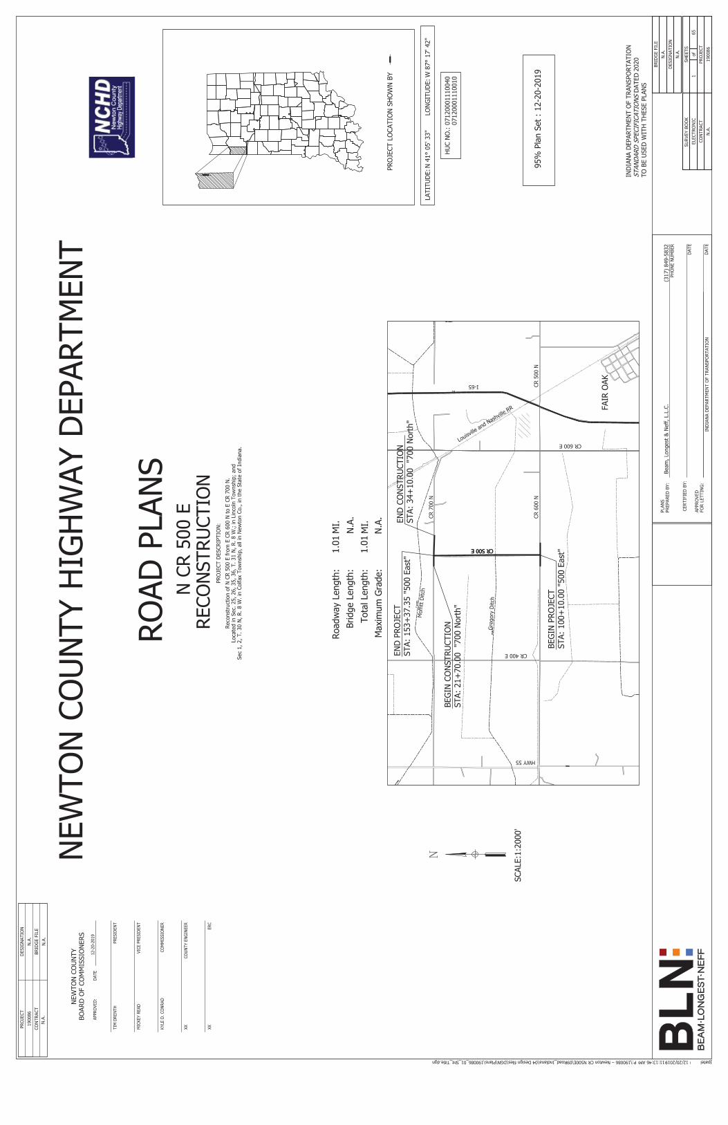
I. PROJECT LOCATION AND DESCRIPTION
The project involves reconstruction of CR N 500 E from CR E 600 N to CR E 700 N, and CR 700 N from approximately 415 feet west of CR 500 N to approximately 885 feet east of CR 500 N in Newton County, Indiana. The existing gravel roadways are approximately 24 feet wide with earthen shoulders. The proposed improvement consists of converting the existing gravel road to an HMA roadway with one 11-foot wide lane in each direction bordered by 2 foot wide paved and 2 foot wide aggregate shoulders. The roadway improvement on CR 500 E begins at Station 100+09.76 and ends at Station 153+48.48 Line “500 East”, for a total length of 5,338.72 feet. The roadway improvement on CR 700 N begins at Station 21+70 and ends at Station 34+10 Line “700 North”, for a total length of 1,240.00 feet. The proposed HMA roadway will be constructed at or near the existing grade with approximately 1-foot of fill in the widening areas. Additionally, end sections will be installed for Structure No. 12 the pipe culvert at Station 122+72 “500 East”.
II. SUBSURFACE INVESTIGATION
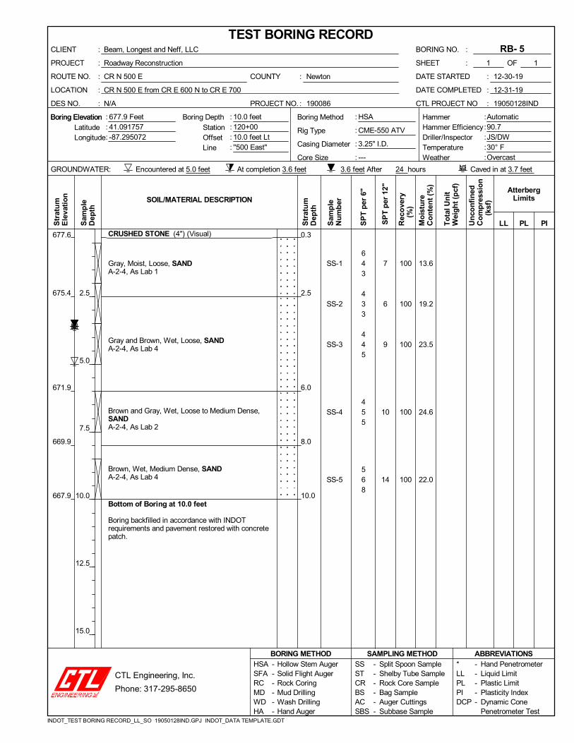
Fifteen (15) roadway test borings, designated as RB-1 through RB-15, were drilled to a depth of 10.0 feet each below the existing grade. Test Borings RB-1 through RB-12 were drilled on CR N 500 E while RB-13, RB-14 and RB-15 were drilled on CR E 700 N. Additionally, one (1) test boring, designated as TB-1 was drilled to a depth of 15 feet on CR N 500 E in the vicinity of the small culvert. The test borings were advanced with an ATV mounted drilling rig utilizing hollow stem augers (HSA) between December 30th, 2019 and January 8th, 2020. Standard Penetration tests were conducted using 140-pound automatic hammers falling 30 inches to drive a 2-inch O.D. split barrel sampler for 18 inches. Soil samples obtained from the drilling operation were preserved in glass jars and visually classified in the field by the drilling crew and in the laboratory by a geotechnical engineer, and tested for Natural Moisture Content. Representative soil samples were tested for Atterberg Limits, Grain Size Distribution, pH, Loss on Ignition and Calcium Carbonate.

Geotechnical Investigation Roadway Reconstruction, CR N 500 E in Newton County, IN CTL Project No.: 19050128IND January 27, 2020 Page 2
Drilling, soil sampling and laboratory testing were performed following standard geotechnical engineering practices, INDOT and current AASHTO/ASTM procedures. Results from field tests are shown on the enclosed Test Boring Records in Appendix B and laboratory test sheets in Appendix C.
Station and offset of the test borings were estimated using the plans prepared by BLN dated 12/13/2019. The points were plotted in Google Earth to estimate Latitude and Longitude and then located using a Trimble Geo7X GPS system. Surface elevation of the test borings were estimated from plans and profiles prepared by BLN. Boring locations and elevation shown on the Boring Location Plans in Appendix A and Test Boring Records in Appendix B should be considered approximate.
III. FINDINGS
A. Subsurface Conditions
The test borings exhibited a surface cover consisting of 4 to 8 inches of gravel, averaging approximately 5 inches in thickness. Below the surface cover, the test borings encountered soils classified as sand of A-2-4 soil category. Samples collected from the upper the existing surficial soils (topsoil) exhibited the results summarized below in Table 1. Laboratory test results are included in Appendix C. Dark gray to black colored sand soils were encountered in all the test borings at depths ranging from 1.2 to 4.5 feet below the existing grade. Loss on ignition test performed on selected samples of this sand exhibited values ranging from 2.7 to 4.0 percent. Natural moisture content values of these foundation soils ranged from 4 to 17 percent. The pH values of the subgrade soils ranged from 7.0 to 7.6 percent. Detailed information of soil types and standard penetration values are shown in the Test Boring Records in Appendix B, laboratory test results in Appendix C and summarized below in Table 2.
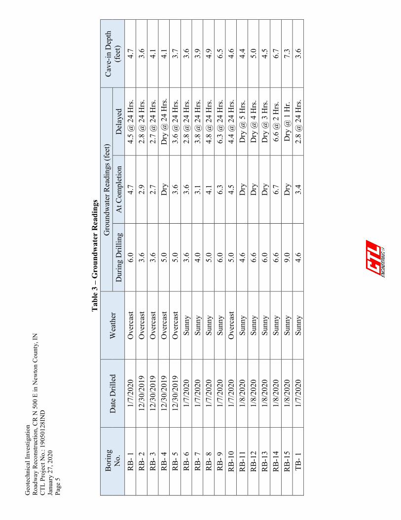
B. Groundwater
Groundwater was encountered in the test borings as shown on the attached Test Boring Records in Appendix B. A summary of groundwater measurements and cave-in depths is provided in Table 3. It should be noted that fluctuations in groundwater levels should be expected over time due to variations in precipitation.

Geo
tech
nica
l Inv
estig
atio
n
Roa
dway
Rec
onst
ruct
ion,
CR
N 5
00 E
in N
ewto
n C
ount
y, IN
C
TL P
roje
ct N
o.: 1
9050
128I
ND
Ja
nuar
y 27
, 202
0
Page
3
T
able
1 –
Top
soil
Tes
t Res
ults
*
Des
. St
atio
n O
ffset
Li
ne
Test
ed
Dep
th
(inch
) pH
G
rave
l Sa
nd
Silt
Cla
y O
rgan
ic C
onte
nt
(% b
y W
eigh
t) Ph
osph
orus
(p
pm)
Pota
ssiu
m
(p
pm)
(% b
y W
eigh
t)
TS-1
10
0+18
16
’ Rt
'500
Eas
t' 2
7.0
1 81
16
2
3.4
83
103
TS-2
12
2+85
15
’ Lt
'500
Eas
t' 2
7.5
4 80
10
6
2.5
47
48
TS-3
15
3+32
15
’ Rt
'500
Eas
t' 2
7.1
25
64
9 3
2.9
82
56
TS-4
22
+00
8’ L
t '7
00 N
orth
' 2
6.7
28
59
12
1 3.
0 30
68
*
All e
xist
ing
tops
oil t
est r
esul
ts p
rese
nted
her
ein
are
for i
nfor
mat
ion
only
.
Tab
le 2
– S
umm
ary
of F
ound
atio
n So
il T
estin
g
Borin
g N
o.
Stat
ion
(feet
) O
ffset
Li
ne
Lab
No.
C
lass
ifica
tion
AA
SHTO
G
roup
In
dex
LL
PL
PI
%
Pass
ing
#200
%
Silt
%
Cla
y %
M
oist
ure
RB-
1
100+
18
16' L
t 50
0 Ea
st
Lab
1 Sa
nd
A-2
-4
NP
NP
NP
13.9
10
.4
3.5
9.0
RB-
2
105+
00
10' R
t 50
0 Ea
st
Lab
1 Sa
nd
A-2
-4
NP
NP
NP
13.9
10
.4
3.5
13.8
R
B- 3
11
0+00
10
' Lt
500
East
La
b 1
Sand
A
-2-4
N
P N
P N
P 13
.9
10.4
3.
5 11
.4
RB-
4
115+
25
9' R
t 50
0 Ea
st
Lab
4 Sa
nd
A-2
-4
NP
NP
NP
17.0
16
.1
0.9
16.7
R
B- 5
12
0+00
10
' Lt
500
East
La
b 1
Sand
A
-2-4
N
P N
P N
P 13
.9
10.4
3.
5 13
.6
RB-
6
125+
00
9' R
t 50
0 Ea
st
Lab
1 Sa
nd
A-2
-4
NP
NP
NP
13.9
10
.4
3.5
13.3
R
B- 7
13
0+00
9'
Lt
500
East
La
b 1
Sand
A
-2-4
N
P N
P N
P 13
.9
10.4
3.
5 11
.7
RB-
8
135+
00
9' R
t 50
0 Ea
st
Lab
1 Sa
nd
A-2
-4
NP
NP
NP
13.9
10
.4
3.5
11.9
R
B- 9
14
0+00
10
' Lt
500
East
La
b 1
Sand
A
-2-4
N
P N
P N
P 13
.9
10.4
3.
5 16
.3
Geo
tech
nica
l Inv
estig
atio
n
Roa
dway
Rec
onst
ruct
ion,
CR
N 5
00 E
in N
ewto
n C
ount
y, IN
C
TL P
roje
ct N
o.: 1
9050
128I
ND
Ja
nuar
y 27
, 202
0
Page
4
Tab
le 2
– S
umm
ary
of F
ound
atio
n So
il T
estin
g
Borin
g N
o.
Stat
ion
(feet
) O
ffset
Li
ne
Lab
No.
C
lass
ifica
tion
AA
SHTO
G
roup
In
dex
LL
PL
PI
%
Pass
ing
#200
%
Silt
%
Cla
y %
M
oist
ure
RB-
10
145+
35
12' R
t 50
0 Ea
st
Lab
1 Sa
nd
A-2
-4
NP
NP
NP
13.9
10
.4
3.5
9.9
RB-
11
150+
00
9' L
t 50
0 Ea
st
Lab
1 Sa
nd
A-2
-4
NP
NP
NP
13.9
10
.4
3.5
17.1
R
B-12
15
3+32
15
' Rt
500
East
La
b 1
Sand
A
-2-4
N
P N
P N
P 13
.9
10.4
3.
5 15
.4
RB-
13
22+0
0 8'
Lt
700
Nor
th
Lab
1 Sa
nd
A-2
-4
NP
NP
NP
13.9
10
.4
3.5
9.2
RB-
14
29+0
0 8'
Lt
700
Nor
th
Lab
5 Sa
nd
A-2
-4
NP
NP
NP
15.5
13
.7
1.8
6.9
RB-
15
34+0
0 9'
Rt
700
Nor
th
Lab
5 Sa
nd
A-2
-4
NP
NP
NP
15.5
13
.7
1.8
3.8
TB- 1
12
2+85
15
' Lt
500
East
La
b 6
Sand
A
-2-4
N
P N
P N
P 13
.2
11.6
1.
6 5.
7 A
vera
ge
NP
NP
NP
14.3
11
.2
3.0
11.6
M
inim
um
NP
NP
NP
13.2
10
.4
0.9
3.8
Max
imum
N
P N
P N
P 17
.0
16.1
3.
5 17
.1
Stan
dard
Dev
iatio
n
NP
NP
NP
0.9
1.7
0.9
4.0
Geo
tech
nica
l Inv
estig
atio
n
Roa
dway
Rec
onst
ruct
ion,
CR
N 5
00 E
in N
ewto
n C
ount
y, IN
C
TL P
roje
ct N
o.: 1
9050
128I
ND
Ja
nuar
y 27
, 202
0
Page
5
T
able
3 –
Gro
undw
ater
Rea
ding
s
Borin
g N
o.
Dat
e D
rille
d W
eath
er
Gro
undw
ater
Rea
ding
s (fe
et)
Cav
e-in
Dep
th
(feet
) D
urin
g D
rillin
g A
t Com
plet
ion
Del
ayed
R
B- 1
1/
7/20
20
Ove
rcas
t 6.
0 4.
7 4.
5 @
24
Hrs
. 4.
7 R
B- 2
12
/30/
2019
O
verc
ast
3.6
2.9
2.8
@ 2
4 H
rs.
3.6
RB-
3
12/3
0/20
19
Ove
rcas
t 3.
6 2.
7 2.
7 @
24
Hrs
. 4.
1 R
B- 4
12
/30/
2019
O
verc
ast
5.0
Dry
D
ry @
24
Hrs
. 4.
1 R
B- 5
12
/30/
2019
O
verc
ast
5.0
3.6
3.6
@ 2
4 H
rs.
3.7
RB-
6
1/7/
2020
Su
nny
3.6
3.6
2.8
@ 2
4 H
rs.
3.6
RB-
7
1/7/
2020
Su
nny
4.0
3.1
3.8
@ 2
4 H
rs.
3.9
RB-
8
1/7/
2020
Su
nny
5.0
4.1
4.8
@ 2
4 H
rs.
4.9
RB-
9
1/7/
2020
Su
nny
6.0
6.3
6.3
@ 2
4 H
rs.
6.5
RB-
10
1/7/
2020
O
verc
ast
5.0
4.5
4.4
@ 2
4 H
rs.
4.6
RB-
11
1/8/
2020
Su
nny
4.6
Dry
D
ry @
5 H
rs.
4.4
RB-
12
1/8/
2020
Su
nny
6.6
Dry
D
ry @
4 H
rs.
5.0
RB-
13
1/8/
2020
Su
nny
6.0
Dry
D
ry @
3 H
rs.
4.5
RB-
14
1/8/
2020
Su
nny
6.6
6.7
6.6
@ 2
Hrs
. 6.
7 R
B-15
1/
8/20
20
Sunn
y 9.
0 D
ry
Dry
@ 1
Hr.
7.3
TB- 1
1/
7/20
20
Sunn
y 4.
6 3.
4 2.
8 @
24
Hrs
. 3.
6

Geotechnical Investigation Roadway Reconstruction, CR N 500 E in Newton County, IN CTL Project No.: 19050128IND January 27, 2020 Page 6
IV. DISCUSSION AND RECOMMENDATIONS
A. Pavement Considerations
The proposed HMA pavement may be designed using the soil parameters provided below in Table 4. The recommended subgrade treatment should be performed in accordance with INDOT Standard Specifications Section 207.
Table 4 – Soil Parameters for Pavement Design
Resilient Modulus (MR) of Prepared Subgrade 9,000 Resilient Modulus (MR) of Natural Subgrade 3,000 Predominant Soil Type Sand (A-2-4) Percent Passing #200 14.3 % Silt 11.2 LL NP PL NP PI NP Depth to Water Table > 2.8 feet below existing grade Natural Density (pcf) of Natural Subgrade 115 % Moisture of Natural Subgrade 12 Organic Content (1)
Marl Content (1) Sulfate Content (ppm) 120 Rock Depth > 15 feet below existing grade Filter Fabric Required for Underdrains 918.02(b) Type 1B (NW) (2)
Subgrade Treatment Type IC or Type IB cement only
(1) Loss on Ignition test indicated 2.7% to 4.0% organic matter and 0.6% to 1.3% calcium carbonate on the upper gray/black colored sand layer.
(2) Underdrain trench < 3 ft. deep.
Geotechnical Investigation Roadway Reconstruction, CR N 500 E in Newton County, IN CTL Project No.: 19050128IND January 27, 2020 Page 7
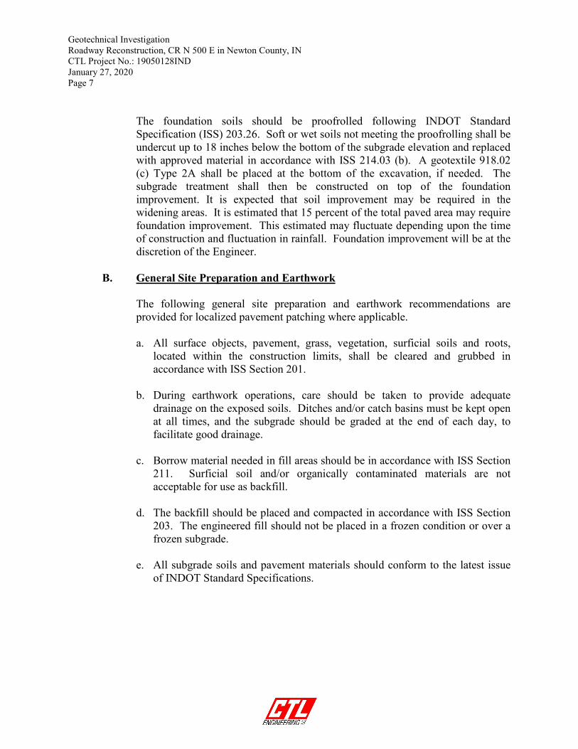
The foundation soils should be proofrolled following INDOT Standard Specification (ISS) 203.26. Soft or wet soils not meeting the proofrolling shall be undercut up to 18 inches below the bottom of the subgrade elevation and replaced with approved material in accordance with ISS 214.03 (b). A geotextile 918.02 (c) Type 2A shall be placed at the bottom of the excavation, if needed. The subgrade treatment shall then be constructed on top of the foundation improvement. It is expected that soil improvement may be required in the widening areas. It is estimated that 15 percent of the total paved area may require foundation improvement. This estimated may fluctuate depending upon the time of construction and fluctuation in rainfall. Foundation improvement will be at the discretion of the Engineer.
B. General Site Preparation and Earthwork
The following general site preparation and earthwork recommendations are provided for localized pavement patching where applicable.
a. All surface objects, pavement, grass, vegetation, surficial soils and roots,
located within the construction limits, shall be cleared and grubbed in accordance with ISS Section 201.
b. During earthwork operations, care should be taken to provide adequate
drainage on the exposed soils. Ditches and/or catch basins must be kept open at all times, and the subgrade should be graded at the end of each day, to facilitate good drainage.
c. Borrow material needed in fill areas should be in accordance with ISS Section 211. Surficial soil and/or organically contaminated materials are not acceptable for use as backfill.
d. The backfill should be placed and compacted in accordance with ISS Section 203. The engineered fill should not be placed in a frozen condition or over a frozen subgrade.
e. All subgrade soils and pavement materials should conform to the latest issue of INDOT Standard Specifications.

Geotechnical Investigation Roadway Reconstruction, CR N 500 E in Newton County, IN CTL Project No.: 19050128IND January 27, 2020 Page 8
V. CONCLUDING REMARKS
The evaluations, conclusions, and recommendations in this report are based on our interpretation of the field and laboratory data obtained during the exploration, information available at the time of this report, our understanding of the project scope at the time of the report and our experience with similar sites and subsurface conditions using generally accepted geotechnical engineering practices. Although individual test borings are representative of the subsurface conditions at the boring locations on the dates drilled, they are not necessarily representative of the subsurface conditions between boring locations or subsurface conditions during other seasons of the year. If the scope of the project changes the recommendations may change and may require additional investigation.
During the design process, it is recommended that CTL work with the project designers to confirm that the geotechnical recommendations are properly incorporated into the final plans and specifications, and to assist with establishing criteria for the construction observation and testing. CTL is not responsible for independent conclusions, opinions and recommendations made by others based on the data and the recommendations provided in this report. The report was prepared by CTL Engineering, Inc. (Consultant) solely for the use of the Client in accordance with an executed contract. The Client’s use of or reliance on this report is limited by the terms and conditions of the contract and by the qualifications and limitations stated in the report. It is also acknowledged that the Client’s use of and reliance of this report is limited for reasons which include: actual site conditions that may change with time; hidden conditions, not discoverable within the scope of the assessment, may exist at the site; and the scope of the investigation may have been limited by time, budget and other constraints imposed by the Client. Neither the report, nor its contents, conclusions nor recommendations are intended for the use of any party other than the Client. Consultant and the Client assume no liability for any reliance placed on this report by such party. The rights of the Client under contract may not be assigned to any person or entity, without the consent of the Consultant which consent shall not be unreasonably withheld.
Geotechnical Investigation Roadway Reconstruction, CR N 500 E in Newton County, IN CTL Project No.: 19050128IND January 27, 2020 Page 9
This geotechnical report does not address the environmental conditions of the site. The Consultant is not responsible for consequences or conditions arising from facts that were concealed, withheld, or not fully disclosed at the time the assessment was conducted.
To the fullest extent permitted by law, the Consultant and Client agree to indemnify and hold each other, and their officers and employees harmless from and against claims, damages, losses and expenses arising out of unknown or concealed conditions. Furthermore, neither the Consultant nor its employees shall be liable to the Owner in an amount in excess of the available professional liability insurance coverage of the Consultant. In addition, Client and Consultant agree neither shall be liable for any special, indirect or consequential damages of any kind or nature.
The Consultant’s services have been provided consistent with its professional standard of care. No other warranties are made, either expressed or implied.
Sincerely, CTL ENGINEERING, INC. Ali Karaki, P.E. Pawan Sigdel, PhD, EIT Principal Engineer Project Engineer

APPENDIX A
GENERAL SITE PLAN BORING LOCATION PLANS

Bor
ing
Loca
tio P
lan
Roa
dway
Rec
onst
ruct
ion
CR
N 5
00 E
from
CR
E 6
00 N
to C
R E
700
NN
ewto
n C
ount
y, IN
Lege
nd
Sta
tion
(Lin
e '7
00 N
')
Sta
tion
(Lin
e '5
00 E
ast')
Test
Bor
ings
900
ft
N
➤➤
N©
201
9 G
oogl
e
© 2
019
Goo
gle
© 2
019
Goo
gle

Bor
ing
Loca
tio P
lan
Roa
dway
Rec
onst
ruct
ion
CR
N 5
00 E
from
CR
E 6
00 N
to C
R E
700
NN
ewto
n C
ount
y, IN
Lege
nd
Sta
tion
(Lin
e '7
00 N
')
Sta
tion
(Lin
e '5
00 E
ast')
Test
Bor
ings
900
ft
N
➤➤
N©
201
9 G
oogl
e
© 2
019
Goo
gle
© 2
019
Goo
gle

Bor
ing
Loca
tio P
lan
Roa
dway
Rec
onst
ruct
ion
CR
N 5
00 E
from
CR
E 6
00 N
to C
R E
700
NN
ewto
n C
ount
y, IN
Lege
nd
Sta
tion
(Lin
e '7
00 N
')
Sta
tion
(Lin
e '5
00 E
ast')
Test
Bor
ings
900
ft
N
➤➤
N©
201
9 G
oogl
e
© 2
019
Goo
gle
© 2
019
Goo
gle

APPENDIX B
TEST BORING RECORDS

SOIL DESCRIPTION
NON-COHESIVE STANDARD PENETRATION SOIL DESCRIPTION BLOWCOUNTS PER FOOT (BPF)
Very Loose ............................................................................ 0 - 5 Loose ................................................................................. 6 - 10 Medium Dense ................................................................... 11 - 30 Dense ............................................................................... 31 - 50 Very Dense ..................................................................... Over 50
COHESIVE SOIL STANDARD PENETRATION DESCRIPTION BLOWCOUNTS PER FOOT (BPF)
Very Soft ............................................................................... 0 - 3 Soft ................................................................................... 4 - 5 Medium Stiff ....................................................................... 6 - 10 Stiff ............................................................................... 11 - 15 Very Stiff ........................................................................... 16 - 30 Hard ............................................................................ Over 30
GRADATION COMPONENT SIZE
Boulders ..................................................................... Retained on 8" Cobbles .................................................... Passing 8" Retained on 3" Gravel ................................................... Passing 3" Retained on #10 Sand ............................................. Passing #10 Retained on #200 Silt ..........................................................0.075 mm to 0.002 mm Clay ......................................................... Smaller than 0.002 mm
MOISTURE TERMS DESCRIPTION
Dry ................................................................................. Powdery Slightly Moist .................................................... Below Plastic Limit Moist ................................................ Above Plastic, Below Liquid Very Moist ......................................................................... At Liquid Wet ....................................................................... Above Liquid

SS-1
SS-2
SS-3
SS-4
SS-5
NP
NP
NP
NP
100
100
100
100
67
677.1
673.3
671.8
667.8
9.0
14.0
20.2
27.2
24.0
CRUSHED STONE (8") with Asphalt (Visual)
Brown and Gray, Moist to Very Moist, MediumDense to Loose, SANDA-2-4 (0), Lab 1
Brown, Wet, Loose, SANDA-2-4, As Lab 4
Gray, Wet, Very Loose to Loose, SANDA-2-4 (0), Lab 2
Bottom of Boring at 10.0 feet
Boring backfilled in accordance with INDOTrequirements and pavement restored with concretepatch.
NP
NP
0.7
4.5
6.0
10.0
699
643
334
223
234
18
7
7
5
7
:
:
:
COUNTY
PROJECT NO.
DATE STARTED
DATE COMPLETED
CTL PROJECT NO
GROUNDWATER:
:::::
CR N 500 E
CR N 500 E from CR E 600 N to CR E 700
N/A
ROUTE NO.
LOCATION
DES NO.
Encountered at 6.0 feet At completion 4.7 feet
Newton
190086
HSA
CME-550 ATV
3.25" I.D.
---
01-07-20
01-08-20
19050128IND
::::
Boring ElevationBoring Elevation Boring Depth HammerHammer EfficiencyDriller/InspectorTemperatureWeather
Caved in at 4.7 feet
:
:
:
:::
StationOffsetLine
Automatic90.7JS/DW30° FOvercast
:
:
24 hours
LatitudeLongitude
677.8 Feet41.086315-87.295015
4.5 feet After
:
:
:
:
Boring Method
Rig Type
Casing Diameter
Core Size
10.0 feet100+1816.0 feet Lt''500 East''
Sam
ple
Dep
th
Un
con
fin
edC
om
pre
ssio
n
(ks
f)
Mo
istu
reC
on
ten
t (%
)
AtterbergLimits
PI
SOIL/MATERIAL DESCRIPTION
Str
atu
mE
leva
tio
n
Str
atu
mD
epth
SP
T p
er 1
2"
Rec
ove
ry
(%
)
LLTo
tal U
nit
Wei
gh
t (p
cf)
PLSam
ple
Nu
mb
er
SP
T p
er 6
"
Hollow Stem AugerSolid Flight AugerRock CoringMud DrillingWash DrillingHand Auger
1
Beam, Longest and Neff, LLC
Roadway Reconstruction
RB- 1:
:
2.5
5.0
7.5
10.0
12.5
15.0
SSSTCRBSACSBS
------
------
SAMPLING METHOD*LLPLPIDCP
Split Spoon SampleShelby Tube SampleRock Core SampleBag SampleAuger CuttingsSubbase Sample
HSASFARCMDWDHA
ABBREVIATIONS
BORING NO.
SHEET OF1
BORING METHODHand PenetrometerLiquid LimitPlastic LimitPlasticity IndexDynamic ConePenetrometer Test
-----
TEST BORING RECORD:
:
CLIENT
PROJECT
INDOT_TEST BORING RECORD_LL_SO 19050128IND.GPJ INDOT_DATA TEMPLATE.GDT
CTL Engineering, Inc.
Phone: 317-295-8650

SS-1
SS-2
SS-3
SS-4
SS-5
19
NP
6
NP
100
100
100
100
56
677.1
675.6
674.1
671.6
667.6
13.8
27.1
22.3
22.3
22.6
CRUSHED STONE (6") (Visual)
Brown and Gray, Moist, Medium Dense, SANDA-2-4, As Lab 1
Brown, Moist, Loose, SANDY LOAMA-2-4 (0), Lab 3
Brown, Very Moist to Wet, Medium Dense to VeryLoose, SANDA-2-4 (0), Lab 4
Gray, Wet, Very Loose, SANDA-2-4, As Lab 2
Bottom of Boring at 10.0 feet
Boring backfilled in accordance with INDOTrequirements and pavement restored with concretepatch.
24
NP
0.5
2.0
3.5
6.0
10.0
767
324
568
422
522
13
6
14
4
4
:
:
:
COUNTY
PROJECT NO.
DATE STARTED
DATE COMPLETED
CTL PROJECT NO
GROUNDWATER:
:::::
CR N 500 E
CR N 500 E from CR E 600 N to CR E 700
N/A
ROUTE NO.
LOCATION
DES NO.
Encountered at 3.6 feet At completion 2.9 feet
Newton
190086
HSA
CME-550 ATV
3.25" I.D.
---
12-30-19
12-31-19
19050128IND
::::
Boring ElevationBoring Elevation Boring Depth HammerHammer EfficiencyDriller/InspectorTemperatureWeather
Caved in at 3.6 feet
:
:
:
:::
StationOffsetLine
Automatic90.7JS/DW30° FOvercast
:
:
24 hours
LatitudeLongitude
677.6 Feet41.087642-87.294936
2.8 feet After
:
:
:
:
Boring Method
Rig Type
Casing Diameter
Core Size
10.0 feet105+0010.0 feet Rt''500 East''
Sam
ple
Dep
th
Un
con
fin
edC
om
pre
ssio
n
(ks
f)
Mo
istu
reC
on
ten
t (%
)
AtterbergLimits
PI
SOIL/MATERIAL DESCRIPTION
Str
atu
mE
leva
tio
n
Str
atu
mD
epth
SP
T p
er 1
2"
Rec
ove
ry
(%
)
LLTo
tal U
nit
Wei
gh
t (p
cf)
PLSam
ple
Nu
mb
er
SP
T p
er 6
"
Hollow Stem AugerSolid Flight AugerRock CoringMud DrillingWash DrillingHand Auger
1
Beam, Longest and Neff, LLC
Roadway Reconstruction
RB- 2:
:
2.5
5.0
7.5
10.0
12.5
15.0
SSSTCRBSACSBS
------
------
SAMPLING METHOD*LLPLPIDCP
Split Spoon SampleShelby Tube SampleRock Core SampleBag SampleAuger CuttingsSubbase Sample
HSASFARCMDWDHA
ABBREVIATIONS
BORING NO.
SHEET OF1
BORING METHODHand PenetrometerLiquid LimitPlastic LimitPlasticity IndexDynamic ConePenetrometer Test
-----
TEST BORING RECORD:
:
CLIENT
PROJECT
INDOT_TEST BORING RECORD_LL_SO 19050128IND.GPJ INDOT_DATA TEMPLATE.GDT
CTL Engineering, Inc.
Phone: 317-295-8650

SS-1
SS-2
SS-3
SS-4
SS-5
78
100
100
100
100
677.1
674.1
671.6
667.6
11.4
28.2
25.8
26.3
21.8
CRUSHED STONE (6") (Visual)
Gray and Brown, Moist, Loose to Very Loose,SANDA-2-4, As Lab 1
Brown, Wet, Loose, SANDA-2-4, As Lab 4
Gray, Wet, Loose to Medium Dense, SANDA-2-4, As Lab 2
Bottom of Boring at 10.0 feet
Boring backfilled in accordance with INDOTrequirements and pavement restored with concretepatch.
0.5
3.5
6.0
10.0
454
322
333
355
458
9
4
6
10
13
:
:
:
COUNTY
PROJECT NO.
DATE STARTED
DATE COMPLETED
CTL PROJECT NO
GROUNDWATER:
:::::
CR N 500 E
CR N 500 E from CR E 600 N to CR E 700
N/A
ROUTE NO.
LOCATION
DES NO.
Encountered at 3.6 feet At completion 2.7 feet
Newton
190086
HSA
CME-550 ATV
3.25" I.D.
---
12-30-19
12-31-19
19050128IND
::::
Boring ElevationBoring Elevation Boring Depth HammerHammer EfficiencyDriller/InspectorTemperatureWeather
Caved in at 4.1 feet
:
:
:
:::
StationOffsetLine
Automatic90.7JS/DW25° FOvercast
:
:
24 hours
LatitudeLongitude
677.6 Feet41.089012-87.295031
2.7 feet After
:
:
:
:
Boring Method
Rig Type
Casing Diameter
Core Size
10.0 feet110+0010.0 feet Lt''500 East''
Sam
ple
Dep
th
Un
con
fin
edC
om
pre
ssio
n
(ks
f)
Mo
istu
reC
on
ten
t (%
)
AtterbergLimits
PI
SOIL/MATERIAL DESCRIPTION
Str
atu
mE
leva
tio
n
Str
atu
mD
epth
SP
T p
er 1
2"
Rec
ove
ry
(%
)
LLTo
tal U
nit
Wei
gh
t (p
cf)
PLSam
ple
Nu
mb
er
SP
T p
er 6
"
Hollow Stem AugerSolid Flight AugerRock CoringMud DrillingWash DrillingHand Auger
1
Beam, Longest and Neff, LLC
Roadway Reconstruction
RB- 3:
:
2.5
5.0
7.5
10.0
12.5
15.0
SSSTCRBSACSBS
------
------
SAMPLING METHOD*LLPLPIDCP
Split Spoon SampleShelby Tube SampleRock Core SampleBag SampleAuger CuttingsSubbase Sample
HSASFARCMDWDHA
ABBREVIATIONS
BORING NO.
SHEET OF1
BORING METHODHand PenetrometerLiquid LimitPlastic LimitPlasticity IndexDynamic ConePenetrometer Test
-----
TEST BORING RECORD:
:
CLIENT
PROJECT
INDOT_TEST BORING RECORD_LL_SO 19050128IND.GPJ INDOT_DATA TEMPLATE.GDT
CTL Engineering, Inc.
Phone: 317-295-8650

SS-1
SS-2
SS-3
SS-4
SS-5
100
100
100
67
100
677.7
677.2
672.4
668.4
7.9
16.7
18.1
20.8
24.2
CRUSHED STONE (8") (Visual)
Gray, Moist, Loose, SANDA-2-4, As Lab 1
Brown, Moist to Wet, Very Loose to Loose, SANDA-2-4, As Lab 4
Brown, Wet, Very Loose to Loose, SANDA-2-4, As Lab 2
Bottom of Boring at 10.0 feet
Boring backfilled in accordance with INDOTrequirements and pavement restored with concretepatch.
0.7
1.2
6.0
10.0
444
323
333
101
334
8
5
6
1
7
:
:
:
COUNTY
PROJECT NO.
DATE STARTED
DATE COMPLETED
CTL PROJECT NO
GROUNDWATER:
:::::
CR N 500 E
CR N 500 E from CR E 600 N to CR E 700
N/A
ROUTE NO.
LOCATION
DES NO.
Encountered at 5.0 feet At completion Dry
Newton
190086
HSA
CME-550 ATV
3.25" I.D.
---
12-30-19
12-31-19
19050128IND
::::
Boring ElevationBoring Elevation Boring Depth HammerHammer EfficiencyDriller/InspectorTemperatureWeather
Caved in at 4.1 feet
:
:
:
:::
StationOffsetLine
Automatic90.7JS/DW25° FOvercast
:
:
24 hours
LatitudeLongitude
678.4 Feet41.090453-87.295003
Dry After
:
:
:
:
Boring Method
Rig Type
Casing Diameter
Core Size
10.0 feet115+259.0 feet Rt''500 East''
Sam
ple
Dep
th
Un
con
fin
edC
om
pre
ssio
n
(ks
f)
Mo
istu
reC
on
ten
t (%
)
AtterbergLimits
PI
SOIL/MATERIAL DESCRIPTION
Str
atu
mE
leva
tio
n
Str
atu
mD
epth
SP
T p
er 1
2"
Rec
ove
ry
(%
)
LLTo
tal U
nit
Wei
gh
t (p
cf)
PLSam
ple
Nu
mb
er
SP
T p
er 6
"
Hollow Stem AugerSolid Flight AugerRock CoringMud DrillingWash DrillingHand Auger
1
Beam, Longest and Neff, LLC
Roadway Reconstruction
RB- 4:
:
2.5
5.0
7.5
10.0
12.5
15.0
SSSTCRBSACSBS
------
------
SAMPLING METHOD*LLPLPIDCP
Split Spoon SampleShelby Tube SampleRock Core SampleBag SampleAuger CuttingsSubbase Sample
HSASFARCMDWDHA
ABBREVIATIONS
BORING NO.
SHEET OF1
BORING METHODHand PenetrometerLiquid LimitPlastic LimitPlasticity IndexDynamic ConePenetrometer Test
-----
TEST BORING RECORD:
:
CLIENT
PROJECT
INDOT_TEST BORING RECORD_LL_SO 19050128IND.GPJ INDOT_DATA TEMPLATE.GDT
CTL Engineering, Inc.
Phone: 317-295-8650
SS-1
SS-2
SS-3
SS-4
SS-5
100
100
100
100
100
677.6
675.4
671.9
669.9
667.9
13.6
19.2
23.5
24.6
22.0
CRUSHED STONE (4") (Visual)
Gray, Moist, Loose, SANDA-2-4, As Lab 1
Gray and Brown, Wet, Loose, SANDA-2-4, As Lab 4
Brown and Gray, Wet, Loose to Medium Dense,SANDA-2-4, As Lab 2
Brown, Wet, Medium Dense, SANDA-2-4, As Lab 4
Bottom of Boring at 10.0 feet
Boring backfilled in accordance with INDOTrequirements and pavement restored with concretepatch.
0.3
2.5
6.0
8.0
10.0
643
433
445
455
568
7
6
9
10
14
:
:
:
COUNTY
PROJECT NO.
DATE STARTED
DATE COMPLETED
CTL PROJECT NO
GROUNDWATER:
:::::
CR N 500 E
CR N 500 E from CR E 600 N to CR E 700
N/A
ROUTE NO.
LOCATION
DES NO.
Encountered at 5.0 feet At completion 3.6 feet
Newton
190086
HSA
CME-550 ATV
3.25" I.D.
---
12-30-19
12-31-19
19050128IND
::::
Boring ElevationBoring Elevation Boring Depth HammerHammer EfficiencyDriller/InspectorTemperatureWeather
Caved in at 3.7 feet
:
:
:
:::
StationOffsetLine
Automatic90.7JS/DW30° FOvercast
:
:
24 hours
LatitudeLongitude
677.9 Feet41.091757-87.295072
3.6 feet After
:
:
:
:
Boring Method
Rig Type
Casing Diameter
Core Size
10.0 feet120+0010.0 feet Lt''500 East''
Sam
ple
Dep
th
Un
con
fin
edC
om
pre
ssio
n
(ks
f)
Mo
istu
reC
on
ten
t (%
)
AtterbergLimits
PI
SOIL/MATERIAL DESCRIPTION
Str
atu
mE
leva
tio
n
Str
atu
mD
epth
SP
T p
er 1
2"
Rec
ove
ry
(%
)
LLTo
tal U
nit
Wei
gh
t (p
cf)
PLSam
ple
Nu
mb
er
SP
T p
er 6
"
Hollow Stem AugerSolid Flight AugerRock CoringMud DrillingWash DrillingHand Auger
1
Beam, Longest and Neff, LLC
Roadway Reconstruction
RB- 5:
:
2.5
5.0
7.5
10.0
12.5
15.0
SSSTCRBSACSBS
------
------
SAMPLING METHOD*LLPLPIDCP
Split Spoon SampleShelby Tube SampleRock Core SampleBag SampleAuger CuttingsSubbase Sample
HSASFARCMDWDHA
ABBREVIATIONS
BORING NO.
SHEET OF1
BORING METHODHand PenetrometerLiquid LimitPlastic LimitPlasticity IndexDynamic ConePenetrometer Test
-----
TEST BORING RECORD:
:
CLIENT
PROJECT
INDOT_TEST BORING RECORD_LL_SO 19050128IND.GPJ INDOT_DATA TEMPLATE.GDT
CTL Engineering, Inc.
Phone: 317-295-8650

SS-1
SS-2
SS-3
SS-4
SS-5
100
100
100
100
100
676.9
673.4
671.9
667.4
13.3
17.7
17.1
25.1
27.1
CRUSHED STONE (6")
Black, Moist to Very Moist, Loose to Very Loose,SANDA-2-4, As Lab 1
Brown, Wet, Very Loose to Loose, SANDA-2-4, As Lab 4
Gray and Brown, Wet, Very Loose to Loose,SANDA-2-4, As Lab 2
Bottom of Boring at 10.0 feet
Boring backfilled in accordance with INDOTrequirements and pavement restored with concretepatch.
0.5
4.0
5.5
10.0
445
313
335
223
324
9
4
8
5
6
:
:
:
COUNTY
PROJECT NO.
DATE STARTED
DATE COMPLETED
CTL PROJECT NO
GROUNDWATER:
:::::
CR N 500 E
CR N 500 E from CR E 600 N to CR E 700
N/A
ROUTE NO.
LOCATION
DES NO.
Encountered at 3.6 feet At completion 3.6 feet
Newton
190086
HSA
CME-550 ATV
3.25" I.D.
---
01-07-20
01-08-20
19050128IND
::::
Boring ElevationBoring Elevation Boring Depth HammerHammer EfficiencyDriller/InspectorTemperatureWeather
Caved in at 3.6 feet
:
:
:
:::
StationOffsetLine
Automatic90.7JS/DW35° FSunny
:
:
24 hours
LatitudeLongitude
677.4 Feet41.093129-87.295009
2.8 feet After
:
:
:
:
Boring Method
Rig Type
Casing Diameter
Core Size
10.0 feet125+009.0 feet Rt''500 East''
Sam
ple
Dep
th
Un
con
fin
edC
om
pre
ssio
n
(ks
f)
Mo
istu
reC
on
ten
t (%
)
AtterbergLimits
PI
SOIL/MATERIAL DESCRIPTION
Str
atu
mE
leva
tio
n
Str
atu
mD
epth
SP
T p
er 1
2"
Rec
ove
ry
(%
)
LLTo
tal U
nit
Wei
gh
t (p
cf)
PLSam
ple
Nu
mb
er
SP
T p
er 6
"
Hollow Stem AugerSolid Flight AugerRock CoringMud DrillingWash DrillingHand Auger
1
Beam, Longest and Neff, LLC
Roadway Reconstruction
RB- 6:
:
2.5
5.0
7.5
10.0
12.5
15.0
SSSTCRBSACSBS
------
------
SAMPLING METHOD*LLPLPIDCP
Split Spoon SampleShelby Tube SampleRock Core SampleBag SampleAuger CuttingsSubbase Sample
HSASFARCMDWDHA
ABBREVIATIONS
BORING NO.
SHEET OF1
BORING METHODHand PenetrometerLiquid LimitPlastic LimitPlasticity IndexDynamic ConePenetrometer Test
-----
TEST BORING RECORD:
:
CLIENT
PROJECT
INDOT_TEST BORING RECORD_LL_SO 19050128IND.GPJ INDOT_DATA TEMPLATE.GDT
CTL Engineering, Inc.
Phone: 317-295-8650

SS-1
SS-2
SS-3
SS-4
SS-5
100
100
100
100
100
677.5
674.8
667.8
11.7
16.3
4.7
24.3
23.3
CRUSHED STONE (4") (Visual)
Black, Moist to Very Moist, Loose, SANDA-2-4, As Lab 1
Gray, Wet, Loose to Very Loose, SANDA-2-4, As Lab 2
Bottom of Boring at 10.0 feet
Boring backfilled in accordance with INDOTrequirements and pavement restored with concretepatch.
0.3
3.0
10.0
655
334
332
213
324
10
7
5
4
6
:
:
:
COUNTY
PROJECT NO.
DATE STARTED
DATE COMPLETED
CTL PROJECT NO
GROUNDWATER:
:::::
CR N 500 E
CR N 500 E from CR E 600 N to CR E 700
N/A
ROUTE NO.
LOCATION
DES NO.
Encountered at 4.0 feet At completion 3.1 feet
Newton
190086
HSA
CME-550 ATV
3.25" I.D.
---
01-07-20
01-08-20
19050128IND
::::
Boring ElevationBoring Elevation Boring Depth HammerHammer EfficiencyDriller/InspectorTemperatureWeather
Caved in at 3.9 feet
:
:
:
:::
StationOffsetLine
Automatic90.7JS/DW35° FSunny
:
:
24 hours
LatitudeLongitude
677.8 Feet41.094502-87.295089
3.8 feet After
:
:
:
:
Boring Method
Rig Type
Casing Diameter
Core Size
10.0 feet130+009.0 feet Lt''500 East''
Sam
ple
Dep
th
Un
con
fin
edC
om
pre
ssio
n
(ks
f)
Mo
istu
reC
on
ten
t (%
)
AtterbergLimits
PI
SOIL/MATERIAL DESCRIPTION
Str
atu
mE
leva
tio
n
Str
atu
mD
epth
SP
T p
er 1
2"
Rec
ove
ry
(%
)
LLTo
tal U
nit
Wei
gh
t (p
cf)
PLSam
ple
Nu
mb
er
SP
T p
er 6
"
Hollow Stem AugerSolid Flight AugerRock CoringMud DrillingWash DrillingHand Auger
1
Beam, Longest and Neff, LLC
Roadway Reconstruction
RB- 7:
:
2.5
5.0
7.5
10.0
12.5
15.0
SSSTCRBSACSBS
------
------
SAMPLING METHOD*LLPLPIDCP
Split Spoon SampleShelby Tube SampleRock Core SampleBag SampleAuger CuttingsSubbase Sample
HSASFARCMDWDHA
ABBREVIATIONS
BORING NO.
SHEET OF1
BORING METHODHand PenetrometerLiquid LimitPlastic LimitPlasticity IndexDynamic ConePenetrometer Test
-----
TEST BORING RECORD:
:
CLIENT
PROJECT
INDOT_TEST BORING RECORD_LL_SO 19050128IND.GPJ INDOT_DATA TEMPLATE.GDT
CTL Engineering, Inc.
Phone: 317-295-8650

SS-1
SS-2
SS-3
SS-4
SS-5
100
100
100
100
100
678.4
676.8
672.8
668.8
11.9
14.4
18.0
26.6
21.3
CRUSHED STONE (5") (Visual)
Black and Gray, Moist, Medium Dense, SANDA-2-4, As Lab 1
Gray and Brown, Wet, Loose to Medium Dense,SANDA-2-4, As Lab 4
Brown and Gray, Wet, Very Loose, SANDA-2-4, As Lab 2
Bottom of Boring at 10.0 feet
Boring backfilled in accordance with INDOTrequirements and pavement restored with concretepatch.
0.4
2.0
6.0
10.0
365
344
356
101
223
11
8
11
1
5
:
:
:
COUNTY
PROJECT NO.
DATE STARTED
DATE COMPLETED
CTL PROJECT NO
GROUNDWATER:
:::::
CR N 500 E
CR N 500 E from CR E 600 N to CR E 700
N/A
ROUTE NO.
LOCATION
DES NO.
Encountered at 5.0 feet At completion 4.1 feet
Newton
190086
HSA
CME-550 ATV
3.25" I.D.
---
01-07-20
01-08-20
19050128IND
::::
Boring ElevationBoring Elevation Boring Depth HammerHammer EfficiencyDriller/InspectorTemperatureWeather
Caved in at 4.9 feet
:
:
:
:::
StationOffsetLine
Automatic90.7JS/DW35° FSunny
:
:
24 hours
LatitudeLongitude
678.8 Feet41.095873-87.295032
4.8 feet After
:
:
:
:
Boring Method
Rig Type
Casing Diameter
Core Size
10.0 feet135+009.0 feet Rt''500 East''
Sam
ple
Dep
th
Un
con
fin
edC
om
pre
ssio
n
(ks
f)
Mo
istu
reC
on
ten
t (%
)
AtterbergLimits
PI
SOIL/MATERIAL DESCRIPTION
Str
atu
mE
leva
tio
n
Str
atu
mD
epth
SP
T p
er 1
2"
Rec
ove
ry
(%
)
LLTo
tal U
nit
Wei
gh
t (p
cf)
PLSam
ple
Nu
mb
er
SP
T p
er 6
"
Hollow Stem AugerSolid Flight AugerRock CoringMud DrillingWash DrillingHand Auger
1
Beam, Longest and Neff, LLC
Roadway Reconstruction
RB- 8:
:
2.5
5.0
7.5
10.0
12.5
15.0
SSSTCRBSACSBS
------
------
SAMPLING METHOD*LLPLPIDCP
Split Spoon SampleShelby Tube SampleRock Core SampleBag SampleAuger CuttingsSubbase Sample
HSASFARCMDWDHA
ABBREVIATIONS
BORING NO.
SHEET OF1
BORING METHODHand PenetrometerLiquid LimitPlastic LimitPlasticity IndexDynamic ConePenetrometer Test
-----
TEST BORING RECORD:
:
CLIENT
PROJECT
INDOT_TEST BORING RECORD_LL_SO 19050128IND.GPJ INDOT_DATA TEMPLATE.GDT
CTL Engineering, Inc.
Phone: 317-295-8650
SS-1
SS-2
SS-3
SS-4
SS-5
100
100
100
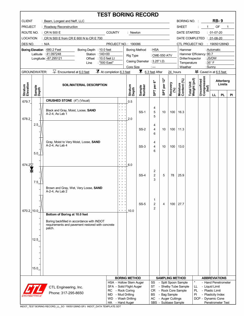
78
100
679.7
678.2
674.2
670.2
16.3
11.3
13.0
25.9
27.7
CRUSHED STONE (4") (Visual)
Black and Gray, Moist, Loose, SANDA-2-4, As Lab 1
Gray, Moist to Very Moist, Loose, SANDA-2-4, As Lab 4
Brown and Gray, Wet, Very Loose, SANDA-2-4, As Lab 2
Bottom of Boring at 10.0 feet
Boring backfilled in accordance with INDOTrequirements and pavement restored with concretepatch.
0.5
2.0
6.0
10.0
455
446
446
223
122
10
10
10
5
4
:
:
:
COUNTY
PROJECT NO.
DATE STARTED
DATE COMPLETED
CTL PROJECT NO
GROUNDWATER:
:::::
CR N 500 E
CR N 500 E from CR E 600 N to CR E 700
N/A
ROUTE NO.
LOCATION
DES NO.
Encountered at 6.0 feet At completion 6.3 feet
Newton
190086
HSA
CME-550 ATV
3.25" I.D.
---
01-07-20
01-08-20
19050128IND
::::
Boring ElevationBoring Elevation Boring Depth HammerHammer EfficiencyDriller/InspectorTemperatureWeather
Caved in at 6.5 feet
:
:
:
:::
StationOffsetLine
Automatic90.7JS/DW35° FSunny
:
:
24 hours
LatitudeLongitude
680.2 Feet41.097248-87.295121
6.3 feet After
:
:
:
:
Boring Method
Rig Type
Casing Diameter
Core Size
10.0 feet140+0010.0 feet Lt''500 East''
Sam
ple
Dep
th
Un
con
fin
edC
om
pre
ssio
n
(ks
f)
Mo
istu
reC
on
ten
t (%
)
AtterbergLimits
PI
SOIL/MATERIAL DESCRIPTION
Str
atu
mE
leva
tio
n
Str
atu
mD
epth
SP
T p
er 1
2"
Rec
ove
ry
(%
)
LLTo
tal U
nit
Wei
gh
t (p
cf)
PLSam
ple
Nu
mb
er
SP
T p
er 6
"
Hollow Stem AugerSolid Flight AugerRock CoringMud DrillingWash DrillingHand Auger
1
Beam, Longest and Neff, LLC
Roadway Reconstruction
RB- 9:
:
2.5
5.0
7.5
10.0
12.5
15.0
SSSTCRBSACSBS
------
------
SAMPLING METHOD*LLPLPIDCP
Split Spoon SampleShelby Tube SampleRock Core SampleBag SampleAuger CuttingsSubbase Sample
HSASFARCMDWDHA
ABBREVIATIONS
BORING NO.
SHEET OF1
BORING METHODHand PenetrometerLiquid LimitPlastic LimitPlasticity IndexDynamic ConePenetrometer Test
-----
TEST BORING RECORD:
:
CLIENT
PROJECT
INDOT_TEST BORING RECORD_LL_SO 19050128IND.GPJ INDOT_DATA TEMPLATE.GDT
CTL Engineering, Inc.
Phone: 317-295-8650
SS-1
SS-2
SS-3
SS-4
SS-5
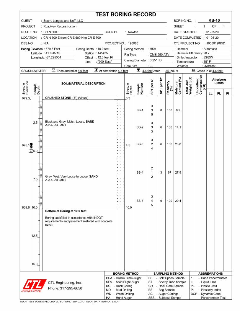
100
100
100
67
100
679.3
675.1
669.6
9.9
14.1
23.0
27.9
20.4
CRUSHED STONE (4") (Visual)
Black and Gray, Moist, Loose, SANDA-2-4, As Lab 1
Gray, Wet, Very Loose to Loose, SANDA-2-4, As Lab 2
Bottom of Boring at 10.0 feet
Boring backfilled in accordance with INDOTrequirements and pavement restored with concretepatch.
0.3
4.5
10.0
335
333
324
212
345
8
6
6
3
9
:
:
:
COUNTY
PROJECT NO.
DATE STARTED
DATE COMPLETED
CTL PROJECT NO
GROUNDWATER:
:::::
CR N 500 E
CR N 500 E from CR E 600 N to CR E 700
N/A
ROUTE NO.
LOCATION
DES NO.
Encountered at 5.0 feet At completion 4.5 feet
Newton
190086
HSA
CME-550 ATV
3.25" I.D.
---
01-07-20
01-08-20
19050128IND
::::
Boring ElevationBoring Elevation Boring Depth HammerHammer EfficiencyDriller/InspectorTemperatureWeather
Caved in at 4.6 feet
:
:
:
:::
StationOffsetLine
Automatic90.7JS/DW35° FOvercast
:
:
24 hours
LatitudeLongitude
679.6 Feet41.098715-87.295054
4.4 feet After
:
:
:
:
Boring Method
Rig Type
Casing Diameter
Core Size
10.0 feet145+3512.0 feet Rt''500 East''
Sam
ple
Dep
th
Un
con
fin
edC
om
pre
ssio
n
(ks
f)
Mo
istu
reC
on
ten
t (%
)
AtterbergLimits
PI
SOIL/MATERIAL DESCRIPTION
Str
atu
mE
leva
tio
n
Str
atu
mD
epth
SP
T p
er 1
2"
Rec
ove
ry
(%
)
LLTo
tal U
nit
Wei
gh
t (p
cf)
PLSam
ple
Nu
mb
er
SP
T p
er 6
"
Hollow Stem AugerSolid Flight AugerRock CoringMud DrillingWash DrillingHand Auger
1
Beam, Longest and Neff, LLC
Roadway Reconstruction
RB-10:
:
2.5
5.0
7.5
10.0
12.5
15.0
SSSTCRBSACSBS
------
------
SAMPLING METHOD*LLPLPIDCP
Split Spoon SampleShelby Tube SampleRock Core SampleBag SampleAuger CuttingsSubbase Sample
HSASFARCMDWDHA
ABBREVIATIONS
BORING NO.
SHEET OF1
BORING METHODHand PenetrometerLiquid LimitPlastic LimitPlasticity IndexDynamic ConePenetrometer Test
-----
TEST BORING RECORD:
:
CLIENT
PROJECT
INDOT_TEST BORING RECORD_LL_SO 19050128IND.GPJ INDOT_DATA TEMPLATE.GDT
CTL Engineering, Inc.
Phone: 317-295-8650

SS-1
SS-2
SS-3
SS-4
SS-5
100
100
100
100
100
679.3
676.6
669.6
17.1
15.7
23.5
25.1
24.4
CRUSHED STONE (4") (Visual)
Brown, Moist, Loose to Very Loose, SANDA-2-4, As Lab 1
Gray and Brown, Moist to Wet, Very Loose toMedium Dense, SANDA-2-4, As Lab 4
Bottom of Boring at 10.0 feet
Boring backfilled in accordance with INDOTrequirements and pavement restored with concretepatch.
0.3
3.0
10.0
654
312
223
346
467
9
3
5
10
13
:
:
:
COUNTY
PROJECT NO.
DATE STARTED
DATE COMPLETED
CTL PROJECT NO
GROUNDWATER:
:::::
CR N 500 E
CR N 500 E from CR E 600 N to CR E 700
N/A
ROUTE NO.
LOCATION
DES NO.
Encountered at 4.6 feet At completion Dry
Newton
190086
HSA
CME-550 ATV
3.25" I.D.
---
01-08-20
01-08-20
19050128IND
::::
Boring ElevationBoring Elevation Boring Depth HammerHammer EfficiencyDriller/InspectorTemperatureWeather
Caved in at 4.4 feet
:
:
:
:::
StationOffsetLine
Automatic90.7JS/DW15° FSunny
:
:
5 hours
LatitudeLongitude
679.6 Feet41.09999-87.295145
Dry After
:
:
:
:
Boring Method
Rig Type
Casing Diameter
Core Size
10.0 feet150+009.0 feet Lt''500 East''
Sam
ple
Dep
th
Un
con
fin
edC
om
pre
ssio
n
(ks
f)
Mo
istu
reC
on
ten
t (%
)
AtterbergLimits
PI
SOIL/MATERIAL DESCRIPTION
Str
atu
mE
leva
tio
n
Str
atu
mD
epth
SP
T p
er 1
2"
Rec
ove
ry
(%
)
LLTo
tal U
nit
Wei
gh
t (p
cf)
PLSam
ple
Nu
mb
er
SP
T p
er 6
"
Hollow Stem AugerSolid Flight AugerRock CoringMud DrillingWash DrillingHand Auger
1
Beam, Longest and Neff, LLC
Roadway Reconstruction
RB-11:
:
2.5
5.0
7.5
10.0
12.5
15.0
SSSTCRBSACSBS
------
------
SAMPLING METHOD*LLPLPIDCP
Split Spoon SampleShelby Tube SampleRock Core SampleBag SampleAuger CuttingsSubbase Sample
HSASFARCMDWDHA
ABBREVIATIONS
BORING NO.
SHEET OF1
BORING METHODHand PenetrometerLiquid LimitPlastic LimitPlasticity IndexDynamic ConePenetrometer Test
-----
TEST BORING RECORD:
:
CLIENT
PROJECT
INDOT_TEST BORING RECORD_LL_SO 19050128IND.GPJ INDOT_DATA TEMPLATE.GDT
CTL Engineering, Inc.
Phone: 317-295-8650

SS-1
SS-2
SS-3
SS-4
SS-5
100
100
100
56
100
679.3
676.6
675.6
669.6
15.4
12.7
26.3
24.7
23.2
CRUSHED STONE (4") (Visual)
Black and Gray, Moist, Loose, SANDA-2-4, As Lab 1
Brown, Moist, Loose to Very Loose, SANDYLOAM (Visual)
Brown, Moist to Wet, Very Loose to MediumDense, SAND with Traces of Clay in SS-3BA-2-4, As Lab 4
Bottom of Boring at 10.0 feet
Boring backfilled in accordance with INDOTrequirements and pavement restored with concretepatch.
0.3
3.0
4.0
10.0
444
333
221
223
5710
8
6
3
5
17
:
:
:
COUNTY
PROJECT NO.
DATE STARTED
DATE COMPLETED
CTL PROJECT NO
GROUNDWATER:
:::::
CR N 500 E
CR N 500 E from CR E 600 N to CR E 700
N/A
ROUTE NO.
LOCATION
DES NO.
Encountered at 6.6 feet At completion Dry
Newton
190086
HSA
CME-550 ATV
3.25" I.D.
---
01-08-20
01-08-20
19050128IND
::::
Boring ElevationBoring Elevation Boring Depth HammerHammer EfficiencyDriller/InspectorTemperatureWeather
Caved in at 5.0 feet
:
:
:
:::
StationOffsetLine
Automatic90.7JS/DW15° FSunny
:
:
4 hours
LatitudeLongitude
679.6 Feet41.100897-87.295068
Dry After
:
:
:
:
Boring Method
Rig Type
Casing Diameter
Core Size
10.0 feet153+3215.0 feet Rt''500 East''
Sam
ple
Dep
th
Un
con
fin
edC
om
pre
ssio
n
(ks
f)
Mo
istu
reC
on
ten
t (%
)
AtterbergLimits
PI
SOIL/MATERIAL DESCRIPTION
Str
atu
mE
leva
tio
n
Str
atu
mD
epth
SP
T p
er 1
2"
Rec
ove
ry
(%
)
LLTo
tal U
nit
Wei
gh
t (p
cf)
PLSam
ple
Nu
mb
er
SP
T p
er 6
"
Hollow Stem AugerSolid Flight AugerRock CoringMud DrillingWash DrillingHand Auger
1
Beam, Longest and Neff, LLC
Roadway Reconstruction
RB-12:
:
2.5
5.0
7.5
10.0
12.5
15.0
SSSTCRBSACSBS
------
------
SAMPLING METHOD*LLPLPIDCP
Split Spoon SampleShelby Tube SampleRock Core SampleBag SampleAuger CuttingsSubbase Sample
HSASFARCMDWDHA
ABBREVIATIONS
BORING NO.
SHEET OF1
BORING METHODHand PenetrometerLiquid LimitPlastic LimitPlasticity IndexDynamic ConePenetrometer Test
-----
TEST BORING RECORD:
:
CLIENT
PROJECT
INDOT_TEST BORING RECORD_LL_SO 19050128IND.GPJ INDOT_DATA TEMPLATE.GDT
CTL Engineering, Inc.
Phone: 317-295-8650

SS-1
SS-2
SS-3
SS-4
SS-5
44
56
67
100
100
678.9
676.2
674.7
669.2
9.2
12.1
13.6
20.0
22.0
CRUSHED STONE (4") (Visual)
Black and Gray, Moist, Loose to Very Loose,SANDA-2-4, As Lab 1
Brown and Gray, Moist, Very Loose to MediumDense, SANDY LOAMA-2-4, As Lab 3
Brown, Wet, Medium Dense, SANDA-2-4, As Lab 4
Bottom of Boring at 10.0 feet
Boring backfilled in accordance with INDOTrequirements and pavement restored with concretepatch.
0.3
3.0
4.5
10.0
655
332
456
457
4511
10
5
11
12
16
:
:
:
COUNTY
PROJECT NO.
DATE STARTED
DATE COMPLETED
CTL PROJECT NO
GROUNDWATER:
:::::
CR N 500 E
CR N 500 E from CR E 600 N to CR E 700
N/A
ROUTE NO.
LOCATION
DES NO.
Encountered at 6.0 feet At completion Dry
Newton
190086
HSA
CME-550 ATV
3.25" I.D.
---
01-08-20
01-08-20
19050128IND
::::
Boring ElevationBoring Elevation Boring Depth HammerHammer EfficiencyDriller/InspectorTemperatureWeather
Caved in at 4.5 feet
:
:
:
:::
StationOffsetLine
Automatic90.7JS/DW15° FSunny
:
:
3 hours
LatitudeLongitude
679.2 Feet41.100974-87.296308
Dry After
:
:
:
:
Boring Method
Rig Type
Casing Diameter
Core Size
10.0 feet22+008.0 feet Lt''700 North''
Sam
ple
Dep
th
Un
con
fin
edC
om
pre
ssio
n
(ks
f)
Mo
istu
reC
on
ten
t (%
)
AtterbergLimits
PI
SOIL/MATERIAL DESCRIPTION
Str
atu
mE
leva
tio
n
Str
atu
mD
epth
SP
T p
er 1
2"
Rec
ove
ry
(%
)
LLTo
tal U
nit
Wei
gh
t (p
cf)
PLSam
ple
Nu
mb
er
SP
T p
er 6
"
Hollow Stem AugerSolid Flight AugerRock CoringMud DrillingWash DrillingHand Auger
1
Beam, Longest and Neff, LLC
Roadway Reconstruction
RB-13:
:
2.5
5.0
7.5
10.0
12.5
15.0
SSSTCRBSACSBS
------
------
SAMPLING METHOD*LLPLPIDCP
Split Spoon SampleShelby Tube SampleRock Core SampleBag SampleAuger CuttingsSubbase Sample
HSASFARCMDWDHA
ABBREVIATIONS
BORING NO.
SHEET OF1
BORING METHODHand PenetrometerLiquid LimitPlastic LimitPlasticity IndexDynamic ConePenetrometer Test
-----
TEST BORING RECORD:
:
CLIENT
PROJECT
INDOT_TEST BORING RECORD_LL_SO 19050128IND.GPJ INDOT_DATA TEMPLATE.GDT
CTL Engineering, Inc.
Phone: 317-295-8650

SS-1
SS-2
SS-3
SS-4
SS-5
100
100
100
100
100
680.5
673.9
670.9
6.9
4.2
14.9
19.4
23.6
CRUSHED STONE (5") (Visual)
Brown, Moist to Wet, Loose to Very Loose, SANDA-2-4, As Lab 5
Brown, Wet, Very Loose, SANDA-2-4, As Lab 2
Bottom of Boring at 10.0 feet
Boring backfilled in accordance with INDOTrequirements and pavement restored with concretepatch.
0.4
7.0
10.0
434
434
322
223
112
7
7
4
5
3
:
:
:
COUNTY
PROJECT NO.
DATE STARTED
DATE COMPLETED
CTL PROJECT NO
GROUNDWATER:
:::::
CR N 500 E
CR N 500 E from CR E 600 N to CR E 700
N/A
ROUTE NO.
LOCATION
DES NO.
Encountered at 6.6 feet At completion 6.7 feet
Newton
190086
HSA
CME-550 ATV
3.25" I.D.
---
01-08-20
01-08-20
19050128IND
::::
Boring ElevationBoring Elevation Boring Depth HammerHammer EfficiencyDriller/InspectorTemperatureWeather
Caved in at 6.7 feet
:
:
:
:::
StationOffsetLine
Automatic90.7JS/DW20° FSunny
:
:
2 hours
LatitudeLongitude
680.9 Feet41.1009-87.291948
6.6 feet After
:
:
:
:
Boring Method
Rig Type
Casing Diameter
Core Size
10.0 feet29+008.0 feet Lt''700 North''
Sam
ple
Dep
th
Un
con
fin
edC
om
pre
ssio
n
(ks
f)
Mo
istu
reC
on
ten
t (%
)
AtterbergLimits
PI
SOIL/MATERIAL DESCRIPTION
Str
atu
mE
leva
tio
n
Str
atu
mD
epth
SP
T p
er 1
2"
Rec
ove
ry
(%
)
LLTo
tal U
nit
Wei
gh
t (p
cf)
PLSam
ple
Nu
mb
er
SP
T p
er 6
"
Hollow Stem AugerSolid Flight AugerRock CoringMud DrillingWash DrillingHand Auger
1
Beam, Longest and Neff, LLC
Roadway Reconstruction
RB-14:
:
2.5
5.0
7.5
10.0
12.5
15.0
SSSTCRBSACSBS
------
------
SAMPLING METHOD*LLPLPIDCP
Split Spoon SampleShelby Tube SampleRock Core SampleBag SampleAuger CuttingsSubbase Sample
HSASFARCMDWDHA
ABBREVIATIONS
BORING NO.
SHEET OF1
BORING METHODHand PenetrometerLiquid LimitPlastic LimitPlasticity IndexDynamic ConePenetrometer Test
-----
TEST BORING RECORD:
:
CLIENT
PROJECT
INDOT_TEST BORING RECORD_LL_SO 19050128IND.GPJ INDOT_DATA TEMPLATE.GDT
CTL Engineering, Inc.
Phone: 317-295-8650
SS-1
SS-2
SS-3
SS-4
SS-5
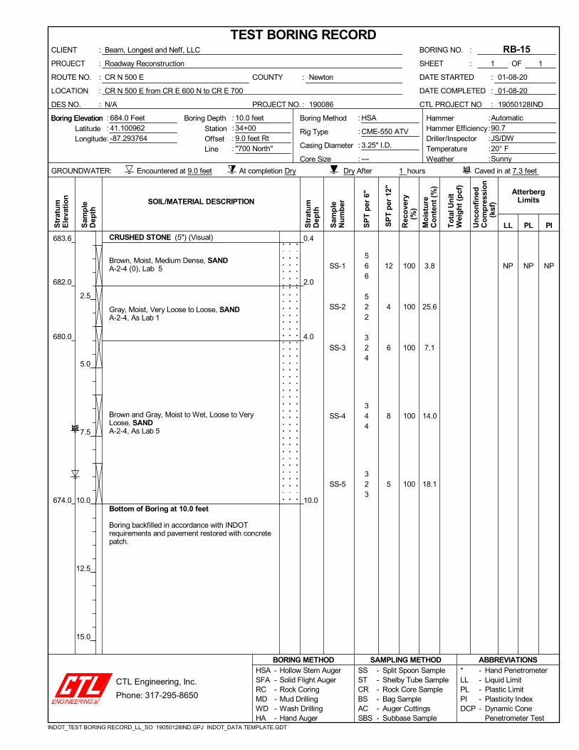
NP NP100
100
100
100
100
683.6
682.0
680.0
674.0
3.8
25.6
7.1
14.0
18.1
CRUSHED STONE (5") (Visual)
Brown, Moist, Medium Dense, SANDA-2-4 (0), Lab 5
Gray, Moist, Very Loose to Loose, SANDA-2-4, As Lab 1
Brown and Gray, Moist to Wet, Loose to VeryLoose, SANDA-2-4, As Lab 5
Bottom of Boring at 10.0 feet
Boring backfilled in accordance with INDOTrequirements and pavement restored with concretepatch.
NP
0.4
2.0
4.0
10.0
566
522
324
344
323
12
4
6
8
5
:
:
:
COUNTY
PROJECT NO.
DATE STARTED
DATE COMPLETED
CTL PROJECT NO
GROUNDWATER:
:::::
CR N 500 E
CR N 500 E from CR E 600 N to CR E 700
N/A
ROUTE NO.
LOCATION
DES NO.
Encountered at 9.0 feet At completion Dry
Newton
190086
HSA
CME-550 ATV
3.25" I.D.
---
01-08-20
01-08-20
19050128IND
::::
Boring ElevationBoring Elevation Boring Depth HammerHammer EfficiencyDriller/InspectorTemperatureWeather
Caved in at 7.3 feet
:
:
:
:::
StationOffsetLine
Automatic90.7JS/DW20° FSunny
:
:
1 hours
LatitudeLongitude
684.0 Feet41.100962-87.293764
Dry After
:
:
:
:
Boring Method
Rig Type
Casing Diameter
Core Size
10.0 feet34+009.0 feet Rt''700 North''
Sam
ple
Dep
th
Un
con
fin
edC
om
pre
ssio
n
(ks
f)
Mo
istu
reC
on
ten
t (%
)
AtterbergLimits
PI
SOIL/MATERIAL DESCRIPTION
Str
atu
mE
leva
tio
n
Str
atu
mD
epth
SP
T p
er 1
2"
Rec
ove
ry
(%
)
LLTo
tal U
nit
Wei
gh
t (p
cf)
PLSam
ple
Nu
mb
er
SP
T p
er 6
"
Hollow Stem AugerSolid Flight AugerRock CoringMud DrillingWash DrillingHand Auger
1
Beam, Longest and Neff, LLC
Roadway Reconstruction
RB-15:
:
2.5
5.0
7.5
10.0
12.5
15.0
SSSTCRBSACSBS
------
------
SAMPLING METHOD*LLPLPIDCP
Split Spoon SampleShelby Tube SampleRock Core SampleBag SampleAuger CuttingsSubbase Sample
HSASFARCMDWDHA
ABBREVIATIONS
BORING NO.
SHEET OF1
BORING METHODHand PenetrometerLiquid LimitPlastic LimitPlasticity IndexDynamic ConePenetrometer Test
-----
TEST BORING RECORD:
:
CLIENT
PROJECT
INDOT_TEST BORING RECORD_LL_SO 19050128IND.GPJ INDOT_DATA TEMPLATE.GDT
CTL Engineering, Inc.
Phone: 317-295-8650

SS-1
SS-2
SS-3
SS-4
SS-5
SS-6
NP
NP
NP
NP
100
78
100
100
100
100
673.3
662.8
5.7
22.9
24.2
21.1
20.5
21.6
Brown, Moist, Loose, SANDA-2-4 (0), Lab 6
Brown and Gray, Wet, Loose to Medium Dense,SANDA-2-4 (0), Lab 7
(Heaving Sand at 12.5 feet).
Bottom of Boring at 15.0 feet
Boring backfilled in accordance with INDOTrequirements and pavement restored with concretepatch.
NP
NP
4.5
15.0
644
333
456
679
565
776
8
6
11
16
11
13
:
:
:
COUNTY
PROJECT NO.
DATE STARTED
DATE COMPLETED
CTL PROJECT NO
GROUNDWATER:
:::::
CR N 500 E
CR N 500 E from CR E 600 N to CR E 700
N/A
ROUTE NO.
LOCATION
DES NO.
Encountered at 4.6 feet At completion 3.4 feet
Newton
190086
HSA
CME-550 ATV
3.25" I.D.
---
01-07-20
01-08-20
19050128IND
::::
Boring ElevationBoring Elevation Boring Depth HammerHammer EfficiencyDriller/InspectorTemperatureWeather
Caved in at 3.6 feet
:
:
:
:::
StationOffsetLine
Automatic90.7JS/DW30° FSunny
:
:
24 hours
LatitudeLongitude
677.8 Feet41.092537-87.295089
2.8 feet After
:
:
:
:
Boring Method
Rig Type
Casing Diameter
Core Size
15.0 feet122+8515.0 feet Lt''500 East''
Sam
ple
Dep
th
Un
con
fin
edC
om
pre
ssio
n
(ks
f)
Mo
istu
reC
on
ten
t (%
)
AtterbergLimits
PI
SOIL/MATERIAL DESCRIPTION
Str
atu
mE
leva
tio
n
Str
atu
mD
epth
SP
T p
er 1
2"
Rec
ove
ry
(%
)
LLTo
tal U
nit
Wei
gh
t (p
cf)
PLSam
ple
Nu
mb
er
SP
T p
er 6
"
Hollow Stem AugerSolid Flight AugerRock CoringMud DrillingWash DrillingHand Auger
1
Beam, Longest and Neff, LLC
Roadway Reconstruction
TB- 1:
:
2.5
5.0
7.5
10.0
12.5
15.0
17.5
20.0
SSSTCRBSACSBS
------
------
SAMPLING METHOD*LLPLPIDCP
Split Spoon SampleShelby Tube SampleRock Core SampleBag SampleAuger CuttingsSubbase Sample
HSASFARCMDWDHA
ABBREVIATIONS
BORING NO.
SHEET OF1
BORING METHODHand PenetrometerLiquid LimitPlastic LimitPlasticity IndexDynamic ConePenetrometer Test
-----
TEST BORING RECORD:
:
CLIENT
PROJECT
INDOT_TEST BORING RECORD_LL_SO 19050128IND.GPJ INDOT_DATA TEMPLATE.GDT
CTL Engineering, Inc.
Phone: 317-295-8650

APPENDIX C
LABORATORY TESTING
Summary of Classification Test Results Grain Size Distribution Curves
Topsoil Analysis Results Summary of Special Laboratory Test Results

Lab
1R
B-
1S
S-2
2.0-
3.5
SA
ND
A-2
-4 (
0)1.
784
.410
.43.
5N
PN
PN
P14
.0
Lab
2R
B-
1S
S-4
6.0-
7.5
SA
ND
A-2
-4 (
0)0.
083
.016
.10.
9N
PN
PN
P27
.2
Lab
3R
B-
2S
S-2
2.0-
3.5
SA
ND
Y L
OA
MA
-2-4
(0)
0.0
70.7
14.7
14.6
24.4
18.5
5.9
27.1
Lab
4R
B-
2S
S-3
3.5-
5.0
SA
ND
A-2
-4 (
0)0.
083
.016
.10.
9N
PN
PN
P22
.3
Lab
5R
B-1
5S
S-1
0.5-
2.0
SA
ND
A-2
-4 (
0)0.
084
.513
.71.
8N
PN
PN
P3.
8
Lab
6T
B-
1S
S-1
1.0-
2.5
SA
ND
A-2
-4 (
0)9.
077
.911
.61.
6N
PN
PN
P5.
7
Lab
7T
B-
1S
S-3
6.0-
7.5
SA
ND
A-2
-4 (
0)0.
084
.913
.41.
7N
PN
PN
P24
.2
Lab
10T
S-1
TS
-10.
0-5.
01.
081
.215
.82.
018
.8
Lab
11T
S-2
TS
-10.
0-5.
04.
179
.99.
86.
212
.3
Lab
12T
S-3
TS
-10.
0-5.
024
.564
.19.
02.
511
.9
Lab
13T
S-4
TS
-10.
0-5.
028
.258
.911
.81.
114
.2
Pla
stic
ityIn
dex
(PI)
Moi
stur
e%
Pla
stic
Lim
it(P
L)
Liqu
idLi
mit
(LL)
San
d%
Silt %
Cla
y%
Gra
vel
%A
AS
HT
OC
lass
ifica
tion
Tex
tura
lC
lass
ifica
tion
Dep
th(f
eet)
Sam
ple
No.
She
et 1
of
1
Lab
No.
Bor
ing
No.
SU
MM
AR
Y O
F C
LA
SS
IFIC
AT
ION
TE
ST
RE
SU
LT
S
: : :1900
86
New
ton
1905
0128
IND
Pro
ject
No.
Cou
nty
CT
L P
roj.
No.
Des
. No.
Pro
ject
Typ
e
Rou
te
Loca
tion
: : : :N/A
Roa
dway
Rec
onst
ruct
ion
CR
N 5
00 E
CR
N 5
00 E
from
CR
E 6
00 N
to C
R E
700
CT
L E
ngin
eerin
g, In
c.P
hone
: 31
7-29
5-86
50
INDOT_SUMMARY_CLASSIFICATION TESTING 19050128IND.GPJ INDOT_4.GDT 1/15/20

0
5
10
15
20
25
30
35
40
45
50
55
60
65
70
75
80
85
90
95
100
0.0010.010.1110100
60
A-2-4(0)
14.0
2.0-3.5
D50
3/81.5 14
HYDROMETER
4 16
RB- 1
84.4
NP
50
Classification
0.041
Easting
10.4
PE
RC
EN
T F
INE
R B
Y W
EIG
HT
Lab 1
GRAIN SIZE DISTRIBUTION
1001
LL
D60
200
D30
0.202
D100 %Sand
Boring No.
406
4.97
1.7
SAND
SS-2
3/4
PL
COBBLES
10
fineSILT
3
Sample
GRAIN SIZE IN MILLIMETERS
NP NP
Remarks
Cu
D10
Depth
GRAVEL CLAY
SAND
%Clay
6 3
1.37
U.S. SIEVE NUMBERS
0.1060.163
30
3.5
4
U.S. SIEVE OPENING IN INCHES
Northing
8
Cc
2
MC
9.525
%Silt
coarse
%Gravel
PI
1401/2 20
:
:
:
:
:CTL Engineering, Inc.Phone: 317-295-8650
Des No.
County
Client
Route
Location
N/A
Newton
Beam, Longest and Neff, LLC
CR N 500 E
CR N 500 E from CR E 600 N to CR E 700
INDOT_GRADATION_NE 19050128IND.GPJ

0
5
10
15
20
25
30
35
40
45
50
55
60
65
70
75
80
85
90
95
100
0.0010.010.1110100
60
A-2-4(0)
27.2
6.0-7.5
D50
3/81.5 14
HYDROMETER
4 16
RB- 1
83.0
NP
50
Classification
0.045
Easting
16.1
PE
RC
EN
T F
INE
R B
Y W
EIG
HT
Lab 2
GRAIN SIZE DISTRIBUTION
1001
LL
D60
200
D30
0.185
D100 %Sand
Boring No.
406
4.12
0.0
SAND
SS-4
3/4
PL
COBBLES
10
fineSILT
3
Sample
GRAIN SIZE IN MILLIMETERS
NP NP
Remarks
Cu
D10
Depth
GRAVEL CLAY
SAND
%Clay
6 3
1.17
U.S. SIEVE NUMBERS
0.0980.15
30
0.9
4
U.S. SIEVE OPENING IN INCHES
Northing
8
Cc
2
MC
2
%Silt
coarse
%Gravel
PI
1401/2 20
:
:
:
:
:CTL Engineering, Inc.Phone: 317-295-8650
Des No.
County
Client
Route
Location
N/A
Newton
Beam, Longest and Neff, LLC
CR N 500 E
CR N 500 E from CR E 600 N to CR E 700
INDOT_GRADATION_NE 19050128IND.GPJ
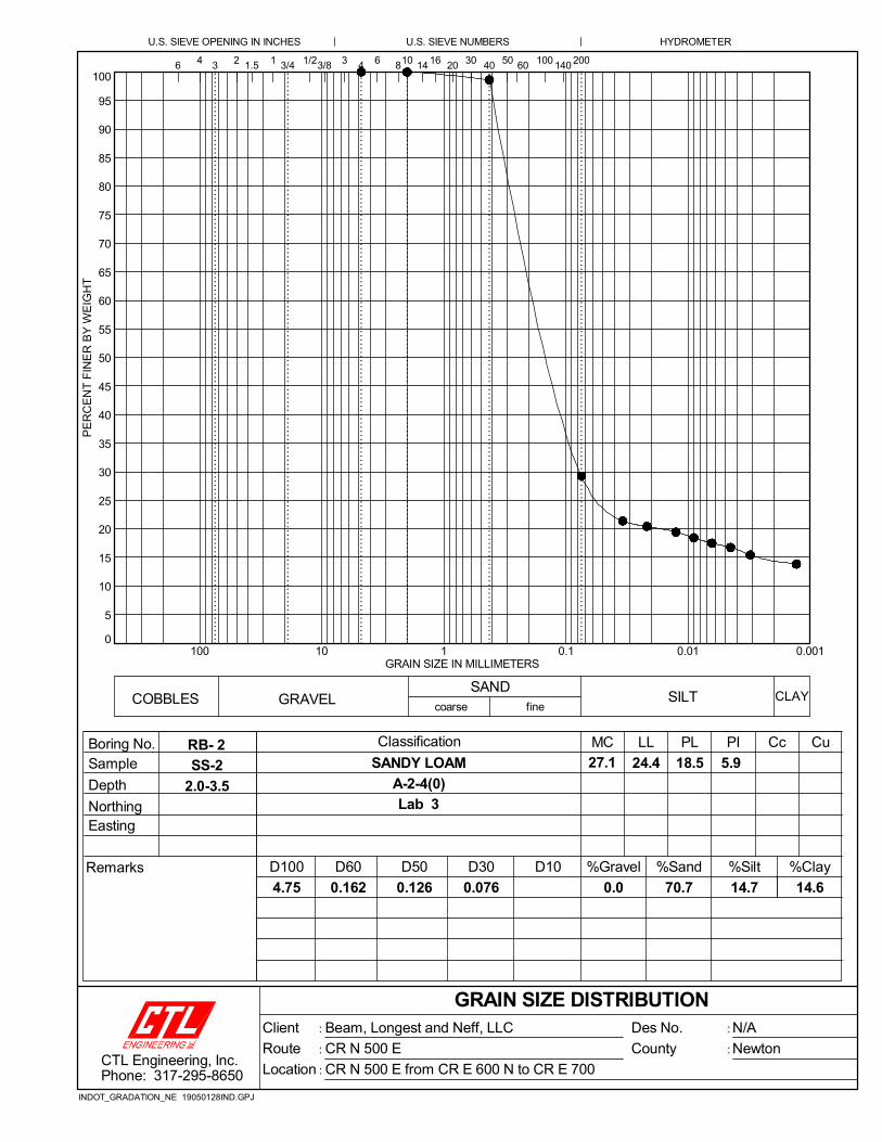
0
5
10
15
20
25
30
35
40
45
50
55
60
65
70
75
80
85
90
95
100
0.0010.010.1110100
60
A-2-4(0)
27.1
2.0-3.5
D50
3/81.5 14
HYDROMETER
4 16
RB- 2
70.7
5.9
50
Classification
Easting
14.7
PE
RC
EN
T F
INE
R B
Y W
EIG
HT
Lab 3
GRAIN SIZE DISTRIBUTION
1001
LL
D60
200
D30
0.162
D100 %Sand
Boring No.
406
0.0
SAND
SS-2
3/4
PL
COBBLES
10
fineSILT
3
Sample
GRAIN SIZE IN MILLIMETERS
24.4 18.5
Remarks
Cu
D10
Depth
GRAVEL CLAY
SANDY LOAM
%Clay
6 3
U.S. SIEVE NUMBERS
0.0760.126
30
14.6
4
U.S. SIEVE OPENING IN INCHES
Northing
8
Cc
2
MC
4.75
%Silt
coarse
%Gravel
PI
1401/2 20
:
:
:
:
:CTL Engineering, Inc.Phone: 317-295-8650
Des No.
County
Client
Route
Location
N/A
Newton
Beam, Longest and Neff, LLC
CR N 500 E
CR N 500 E from CR E 600 N to CR E 700
INDOT_GRADATION_NE 19050128IND.GPJ
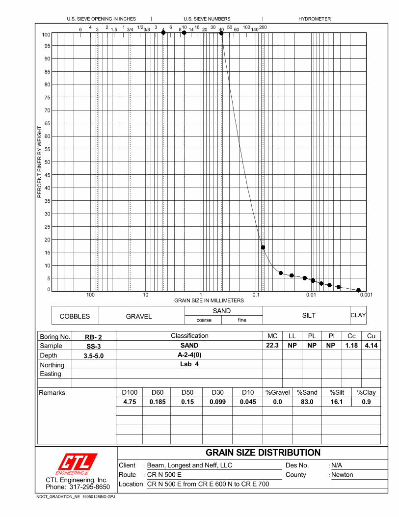
0
5
10
15
20
25
30
35
40
45
50
55
60
65
70
75
80
85
90
95
100
0.0010.010.1110100
60
A-2-4(0)
22.3
3.5-5.0
D50
3/81.5 14
HYDROMETER
4 16
RB- 2
83.0
NP
50
Classification
0.045
Easting
16.1
PE
RC
EN
T F
INE
R B
Y W
EIG
HT
Lab 4
GRAIN SIZE DISTRIBUTION
1001
LL
D60
200
D30
0.185
D100 %Sand
Boring No.
406
4.14
0.0
SAND
SS-3
3/4
PL
COBBLES
10
fineSILT
3
Sample
GRAIN SIZE IN MILLIMETERS
NP NP
Remarks
Cu
D10
Depth
GRAVEL CLAY
SAND
%Clay
6 3
1.18
U.S. SIEVE NUMBERS
0.0990.15
30
0.9
4
U.S. SIEVE OPENING IN INCHES
Northing
8
Cc
2
MC
4.75
%Silt
coarse
%Gravel
PI
1401/2 20
:
:
:
:
:CTL Engineering, Inc.Phone: 317-295-8650
Des No.
County
Client
Route
Location
N/A
Newton
Beam, Longest and Neff, LLC
CR N 500 E
CR N 500 E from CR E 600 N to CR E 700
INDOT_GRADATION_NE 19050128IND.GPJ

0
5
10
15
20
25
30
35
40
45
50
55
60
65
70
75
80
85
90
95
100
0.0010.010.1110100
60
A-2-4(0)
3.8
0.5-2.0
D50
3/81.5 14
HYDROMETER
4 16
RB-15
84.5
NP
50
Classification
0.045
Easting
13.7
PE
RC
EN
T F
INE
R B
Y W
EIG
HT
Lab 5
GRAIN SIZE DISTRIBUTION
1001
LL
D60
200
D30
0.193
D100 %Sand
Boring No.
406
4.29
0.0
SAND
SS-1
3/4
PL
COBBLES
10
fineSILT
3
Sample
GRAIN SIZE IN MILLIMETERS
NP NP
Remarks
Cu
D10
Depth
GRAVEL CLAY
SAND
%Clay
6 3
1.20
U.S. SIEVE NUMBERS
0.1020.156
30
1.8
4
U.S. SIEVE OPENING IN INCHES
Northing
8
Cc
2
MC
2
%Silt
coarse
%Gravel
PI
1401/2 20
:
:
:
:
:CTL Engineering, Inc.Phone: 317-295-8650
Des No.
County
Client
Route
Location
N/A
Newton
Beam, Longest and Neff, LLC
CR N 500 E
CR N 500 E from CR E 600 N to CR E 700
INDOT_GRADATION_NE 19050128IND.GPJ

0
5
10
15
20
25
30
35
40
45
50
55
60
65
70
75
80
85
90
95
100
0.0010.010.1110100
60
A-2-4(0)
5.7
1.0-2.5
D50
3/81.5 14
HYDROMETER
4 16
TB- 1
77.9
NP
50
Classification
0.052
Easting
11.5
PE
RC
EN
T F
INE
R B
Y W
EIG
HT
Lab 6
GRAIN SIZE DISTRIBUTION
1001
LL
D60
200
D30
0.223
D100 %Sand
Boring No.
406
4.29
9.0
SAND
SS-1
3/4
PL
COBBLES
10
fineSILT
3
Sample
GRAIN SIZE IN MILLIMETERS
NP NP
Remarks
Cu
D10
Depth
GRAVEL CLAY
SAND
%Clay
6 3
1.06
U.S. SIEVE NUMBERS
0.1110.177
30
1.6
4
U.S. SIEVE OPENING IN INCHES
Northing
8
Cc
2
MC
19
%Silt
coarse
%Gravel
PI
1401/2 20
:
:
:
:
:CTL Engineering, Inc.Phone: 317-295-8650
Des No.
County
Client
Route
Location
N/A
Newton
Beam, Longest and Neff, LLC
CR N 500 E
CR N 500 E from CR E 600 N to CR E 700
INDOT_GRADATION_NE 19050128IND.GPJ

0
5
10
15
20
25
30
35
40
45
50
55
60
65
70
75
80
85
90
95
100
0.0010.010.1110100
60
A-2-4(0)
24.2
6.0-7.5
D50
3/81.5 14
HYDROMETER
4 16
TB- 1
84.9
NP
50
Classification
0.045
Easting
13.4
PE
RC
EN
T F
INE
R B
Y W
EIG
HT
Lab 7
GRAIN SIZE DISTRIBUTION
1001
LL
D60
200
D30
0.19
D100 %Sand
Boring No.
406
4.25
0.0
SAND
SS-3
3/4
PL
COBBLES
10
fineSILT
3
Sample
GRAIN SIZE IN MILLIMETERS
NP NP
Remarks
Cu
D10
Depth
GRAVEL CLAY
SAND
%Clay
6 3
1.23
U.S. SIEVE NUMBERS
0.1020.154
30
1.7
4
U.S. SIEVE OPENING IN INCHES
Northing
8
Cc
2
MC
2
%Silt
coarse
%Gravel
PI
1401/2 20
:
:
:
:
:CTL Engineering, Inc.Phone: 317-295-8650
Des No.
County
Client
Route
Location
N/A
Newton
Beam, Longest and Neff, LLC
CR N 500 E
CR N 500 E from CR E 600 N to CR E 700
INDOT_GRADATION_NE 19050128IND.GPJ

0
5
10
15
20
25
30
35
40
45
50
55
60
65
70
75
80
85
90
95
100
0.0010.010.1110100
60
A-2-4(0)
18.8
0.0-5.0
D50
3/81.5 14
HYDROMETER
4 16
TS-1
81.2
NP
50
Classification
0.032
Easting
15.8
PE
RC
EN
T F
INE
R B
Y W
EIG
HT
Lab 10
GRAIN SIZE DISTRIBUTION
1001
LL
D60
200
D30
0.189
D100 %Sand
Boring No.
406
5.84
1.0
SAND
TS-1
3/4
PL
COBBLES
10
fineSILT
3
Sample
GRAIN SIZE IN MILLIMETERS
NP NP
Remarks
Cu
D10
Depth
GRAVEL CLAY
SAND
%Clay
6 3
1.56
U.S. SIEVE NUMBERS
0.0980.152
30
2.0
4
U.S. SIEVE OPENING IN INCHES
Northing
8
Cc
2
MC
19
%Silt
coarse
%Gravel
PI
1401/2 20
:
:
:
:
:CTL Engineering, Inc.Phone: 317-295-8650
Des No.
County
Client
Route
Location
N/A
Newton
Beam, Longest and Neff, LLC
CR N 500 E
CR N 500 E from CR E 600 N to CR E 700
INDOT_GRADATION_NE 19050128IND.GPJ

0
5
10
15
20
25
30
35
40
45
50
55
60
65
70
75
80
85
90
95
100
0.0010.010.1110100
60
A-2-4(0)
12.3
0.0-5.0
D50
3/81.5 14
HYDROMETER
4 16
TS-2
79.9
NP
50
Classification
0.009
Easting
9.8
PE
RC
EN
T F
INE
R B
Y W
EIG
HT
Lab 11
GRAIN SIZE DISTRIBUTION
1001
LL
D60
200
D30
0.203
D100 %Sand
Boring No.
406
22.22
4.1
SAND
TS-1
3/4
PL
COBBLES
10
fineSILT
3
Sample
GRAIN SIZE IN MILLIMETERS
NP NP
Remarks
Cu
D10
Depth
GRAVEL CLAY
SAND
%Clay
6 3
5.70
U.S. SIEVE NUMBERS
0.1030.162
30
6.2
4
U.S. SIEVE OPENING IN INCHES
Northing
8
Cc
2
MC
19
%Silt
coarse
%Gravel
PI
1401/2 20
:
:
:
:
:CTL Engineering, Inc.Phone: 317-295-8650
Des No.
County
Client
Route
Location
N/A
Newton
Beam, Longest and Neff, LLC
CR N 500 E
CR N 500 E from CR E 600 N to CR E 700
INDOT_GRADATION_NE 19050128IND.GPJ

0
5
10
15
20
25
30
35
40
45
50
55
60
65
70
75
80
85
90
95
100
0.0010.010.1110100
60
A-2-4(0)
11.9
0.0-5.0
D50
3/81.5 14
HYDROMETER
4 16
TS-3
64.1
NP
50
Classification
0.058
Easting
8.9
PE
RC
EN
T F
INE
R B
Y W
EIG
HT
Lab 12
GRAIN SIZE DISTRIBUTION
1001
LL
D60
200
D30
0.351
D100 %Sand
Boring No.
406
6.01
24.5
SAND
TS-1
3/4
PL
COBBLES
10
fineSILT
3
Sample
GRAIN SIZE IN MILLIMETERS
NP NP
Remarks
Cu
D10
Depth
GRAVEL CLAY
SAND
%Clay
6 3
0.89
U.S. SIEVE NUMBERS
0.1350.255
30
2.5
4
U.S. SIEVE OPENING IN INCHES
Northing
8
Cc
2
MC
25.4
%Silt
coarse
%Gravel
PI
1401/2 20
:
:
:
:
:CTL Engineering, Inc.Phone: 317-295-8650
Des No.
County
Client
Route
Location
N/A
Newton
Beam, Longest and Neff, LLC
CR N 500 E
CR N 500 E from CR E 600 N to CR E 700
INDOT_GRADATION_NE 19050128IND.GPJ

0
5
10
15
20
25
30
35
40
45
50
55
60
65
70
75
80
85
90
95
100
0.0010.010.1110100
60
A-2-4(0)
14.2
0.0-5.0
D50
3/81.5 14
HYDROMETER
4 16
TS-4
58.9
NP
50
Classification
0.055
Easting
11.8
PE
RC
EN
T F
INE
R B
Y W
EIG
HT
Lab 13
GRAIN SIZE DISTRIBUTION
1001
LL
D60
200
D30
0.34
D100 %Sand
Boring No.
406
6.12
28.2
SAND
TS-1
3/4
PL
COBBLES
10
fineSILT
3
Sample
GRAIN SIZE IN MILLIMETERS
NP NP
Remarks
Cu
D10
Depth
GRAVEL CLAY
SAND
%Clay
6 3
0.89
U.S. SIEVE NUMBERS
0.130.246
30
1.1
4
U.S. SIEVE OPENING IN INCHES
Northing
8
Cc
2
MC
19
%Silt
coarse
%Gravel
PI
1401/2 20
:
:
:
:
:CTL Engineering, Inc.Phone: 317-295-8650
Des No.
County
Client
Route
Location
N/A
Newton
Beam, Longest and Neff, LLC
CR N 500 E
CR N 500 E from CR E 600 N to CR E 700
INDOT_GRADATION_NE 19050128IND.GPJ

Rev
11/
17D
ate:
Des
. No.
:Pr
ojec
t:Lo
catio
n:
REF
.A
ASH
TO T
28
9
AA
SHTO
T 88
and
T
89
AA
SHTO
T 88
and
T
89
AA
SHTO
T 88
and
T
89
AA
SHTO
T 88
and
T
89
AA
SHTO
T 26
7 an
d
T 21
**
Bra
y P-
1 Eq
uiva
lent
NC
RR
P 22
1,
Cha
pt 7
***
Gra
vel*
Sand
Silt
Cla
y
TS-1
100+
1816
Rt
27.
01
8116
23.
483
103
TS-2
122+
8515
Lt2
7.5
480
106
2.5
4748
TS-3
153+
3215
Rt
27.
125
649
32.
982
56TS
-422
+00
8Lt
26.
728
5912
13.
030
68
6.0
- 7.3
N/A
5 - 5
0%30
- 80
%5
- 30%
3 - 1
0%**
20 -
8010
5 - 2
50
* **In
Dav
ies,
Gib
son,
Kno
x, P
ike
Pose
y, a
nd V
ande
rbur
gh C
ount
ies,
AA
SHTO
T 2
1 sh
all a
lso
be p
erfo
rmed
. A
ccep
tabl
e ra
nge
is 4
- 10
%**
*N
orth
Cen
tral R
egio
nal R
esea
rch
Publ
icat
ion
221,
Cha
pter
7
Bor
ing
Log
Stat
ion
(% b
y W
eigh
t)
pH
LOC
ATI
ON
Org
anic
C
onte
nt
(%
by
Wt)
IND
IAN
A D
EPA
RTM
ENT
OF
TRA
NSP
OR
TATI
ON
1/13
/202
0N
/AR
oadw
ay R
econ
stru
ctio
nC
R N
500
E fr
om C
R E
600
N to
CR
E 7
00 N
AN
ALY
SIS
OFF
ICE
OF
GEO
TEC
HN
ICA
L SE
RV
ICES
Sum
mar
y of
Exi
stin
g To
psoi
l Tes
t Res
ults
for u
se w
ith P
lant
Gro
wth
Lay
er
Not
e: A
ll ex
istin
g to
psoi
l tes
t res
ults
pre
sent
ed h
erei
n ar
e fo
r inf
orm
atio
n on
ly.
For i
nfor
mat
iona
l pur
pose
s onl
y
Acc
epta
ble
Ran
ges p
er 9
14.0
1 =
Off
set
(fee
t)Lt
/Rt
Test
ed
Dep
th
(inch
)
Phos
phor
us
(ppm
)Po
tass
ium
(ppm
)

RB
- 1
SS
-10.
5-2.
09.
0
RB
- 1
SS
-22.
0-3.
514
.07.
1
RB
- 1
SS
-33.
5-5.
020
.2
RB
- 1
SS
-46.
0-7.
527
.27.
0
RB
- 1
SS
-58.
5-10
.024
.0
RB
- 2
SS
-10.
5-2.
013
.83.
80.
8
RB
- 2
SS
-22.
0-3.
527
.112
07.
3
RB
- 2
SS
-33.
5-5.
022
.37.
6
RB
- 2
SS
-46.
0-7.
522
.3
RB
- 2
SS
-58.
5-10
.022
.6
RB
- 3
SS
-10.
5-2.
011
.43.
21.
3
RB
- 3
SS
-22.
0-3.
528
.2
RB
- 3
SS
-33.
5-5.
025
.8
RB
- 3
SS
-46.
0-7.
526
.3
RB
- 3
SS
-58.
5-10
.021
.8
RB
- 4
SS
-10.
5-2.
07.
9
RB
- 4
SS
-22.
0-3.
516
.7
RB
- 4
SS
-33.
5-5.
018
.1
RB
- 4
SS
-46.
0-7.
520
.8
RB
- 4
SS
-58.
5-10
.024
.2
RB
- 5
SS
-10.
5-2.
013
.62.
70.
9
RB
- 5
SS
-22.
0-3.
519
.2
RB
- 5
SS
-33.
5-5.
023
.5
RB
- 5
SS
-46.
0-7.
524
.6
RB
- 5
SS
-58.
5-10
.022
.0
RB
- 6
SS
-10.
5-2.
013
.33.
50.
6
Dep
thS
ampl
eB
orin
g
She
et 1
of
4W
etD
ensi
ty(p
cf)
Dry
Den
sity
(pcf
)@
Opt
.pH
Cal
cium
Car
bona
te(%
)LO
I(%
)P
otas
sium
(ppm
)M
oist
ure
%
Max
Dry
Den
sity
(pcf
)Q
u(k
sf)
c(k
sf)
Opt
imum
Moi
stur
e%
SU
MM
AR
Y O
F S
PE
CIA
L L
AB
OR
AT
OR
Y T
ES
T R
ES
UL
TS
In-s
itu+
2% o
f O
pt.
Res
ilien
tM
odul
usP
hosp
horu
s(p
pm)
Sul
fate
(ppm
)
: : :1900
86
New
ton
1905
0128
IND
Pro
ject
No.
Cou
nty
CT
L P
roj.
No.
Des
. No.
Pro
ject
Typ
e
Rou
te
Loca
tion
: : : :N/A
Roa
dway
Rec
onst
ruct
ion
CR
N 5
00 E
CR
N 5
00 E
from
CR
E 6
00 N
to C
R E
700
CT
L E
ngin
eerin
g, In
c.P
hone
: 31
7-29
5-86
50
INDOT_SUMMARY_SPECIAL TESTING 19050128IND.GPJ INDOT_4.GDT 1/24/20

RB
- 6
SS
-22.
0-3.
517
.7
RB
- 6
SS
-33.
5-5.
017
.1
RB
- 6
SS
-46.
0-7.
525
.1
RB
- 6
SS
-58.
5-10
.027
.1
RB
- 7
SS
-10.
5-2.
011
.7
RB
- 7
SS
-22.
0-3.
516
.3
RB
- 7
SS
-33.
5-5.
04.
7
RB
- 7
SS
-46.
0-7.
524
.3
RB
- 7
SS
-58.
5-10
.023
.3
RB
- 8
SS
-10.
5-2.
011
.9
RB
- 8
SS
-22.
0-3.
514
.4
RB
- 8
SS
-33.
5-5.
018
.0
RB
- 8
SS
-46.
0-7.
526
.6
RB
- 8
SS
-58.
5-10
.021
.3
RB
- 9
SS
-10.
5-2.
016
.3
RB
- 9
SS
-22.
0-3.
511
.3
RB
- 9
SS
-33.
5-5.
013
.0
RB
- 9
SS
-46.
0-7.
525
.9
RB
- 9
SS
-58.
5-10
.027
.7
RB
-10
SS
-10.
5-2.
09.
9
RB
-10
SS
-22.
0-3.
514
.1
RB
-10
SS
-33.
5-5.
023
.0
RB
-10
SS
-46.
0-7.
527
.9
RB
-10
SS
-58.
5-10
.020
.4
RB
-11
SS
-10.
5-2.
017
.14.
00.
9
RB
-11
SS
-22.
0-3.
515
.7
Dep
thS
ampl
eB
orin
g
She
et 2
of
4W
etD
ensi
ty(p
cf)
Dry
Den
sity
(pcf
)@
Opt
.pH
Cal
cium
Car
bona
te(%
)LO
I(%
)P
otas
sium
(ppm
)M
oist
ure
%
Max
Dry
Den
sity
(pcf
)Q
u(k
sf)
c(k
sf)
Opt
imum
Moi
stur
e%
SU
MM
AR
Y O
F S
PE
CIA
L L
AB
OR
AT
OR
Y T
ES
T R
ES
UL
TS
In-s
itu+
2% o
f O
pt.
Res
ilien
tM
odul
usP
hosp
horu
s(p
pm)
Sul
fate
(ppm
)
: : :1900
86
New
ton
1905
0128
IND
Pro
ject
No.
Cou
nty
CT
L P
roj.
No.
Des
. No.
Pro
ject
Typ
e
Rou
te
Loca
tion
: : : :N/A
Roa
dway
Rec
onst
ruct
ion
CR
N 5
00 E
CR
N 5
00 E
from
CR
E 6
00 N
to C
R E
700
CT
L E
ngin
eerin
g, In
c.P
hone
: 31
7-29
5-86
50
INDOT_SUMMARY_SPECIAL TESTING 19050128IND.GPJ INDOT_4.GDT 1/24/20

RB
-11
SS
-33.
5-5.
023
.5
RB
-11
SS
-46.
0-7.
525
.1
RB
-11
SS
-58.
5-10
.024
.4
RB
-12
SS
-10.
5-2.
015
.4
RB
-12
SS
-22.
0-3.
512
.7
RB
-12
SS
-33.
5-5.
026
.3
RB
-12
SS
-46.
0-7.
524
.7
RB
-12
SS
-58.
5-10
.023
.2
RB
-13
SS
-10.
5-2.
09.
2
RB
-13
SS
-22.
0-3.
512
.1
RB
-13
SS
-33.
5-5.
013
.6
RB
-13
SS
-46.
0-7.
520
.0
RB
-13
SS
-58.
5-10
.022
.0
RB
-14
SS
-10.
5-2.
06.
9
RB
-14
SS
-22.
0-3.
54.
2
RB
-14
SS
-33.
5-5.
014
.9
RB
-14
SS
-46.
0-7.
519
.4
RB
-14
SS
-58.
5-10
.023
.6
RB
-15
SS
-10.
5-2.
03.
87.
4
RB
-15
SS
-22.
0-3.
525
.6
RB
-15
SS
-33.
5-5.
07.
1
RB
-15
SS
-46.
0-7.
514
.0
RB
-15
SS
-58.
5-10
.018
.1
TB
- 1
SS
-11.
0-2.
55.
712
07.
2
TB
- 1
SS
-23.
5-5.
022
.9
TB
- 1
SS
-36.
0-7.
524
.27.
4
Dep
thS
ampl
eB
orin
g
She
et 3
of
4W
etD
ensi
ty(p
cf)
Dry
Den
sity
(pcf
)@
Opt
.pH
Cal
cium
Car
bona
te(%
)LO
I(%
)P
otas
sium
(ppm
)M
oist
ure
%
Max
Dry
Den
sity
(pcf
)Q
u(k
sf)
c(k
sf)
Opt
imum
Moi
stur
e%
SU
MM
AR
Y O
F S
PE
CIA
L L
AB
OR
AT
OR
Y T
ES
T R
ES
UL
TS
In-s
itu+
2% o
f O
pt.
Res
ilien
tM
odul
usP
hosp
horu
s(p
pm)
Sul
fate
(ppm
)
: : :1900
86
New
ton
1905
0128
IND
Pro
ject
No.
Cou
nty
CT
L P
roj.
No.
Des
. No.
Pro
ject
Typ
e
Rou
te
Loca
tion
: : : :N/A
Roa
dway
Rec
onst
ruct
ion
CR
N 5
00 E
CR
N 5
00 E
from
CR
E 6
00 N
to C
R E
700
CT
L E
ngin
eerin
g, In
c.P
hone
: 31
7-29
5-86
50
INDOT_SUMMARY_SPECIAL TESTING 19050128IND.GPJ INDOT_4.GDT 1/24/20
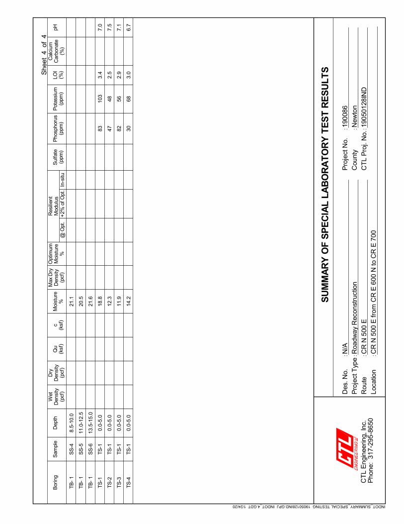
TB
- 1
SS
-48.
5-10
.021
.1
TB
- 1
SS
-511
.0-1
2.5
20.5
TB
- 1
SS
-613
.5-1
5.0
21.6
TS
-1T
S-1
0.0-
5.0
18.8
8310
33.
47.
0
TS
-2T
S-1
0.0-
5.0
12.3
4748
2.5
7.5
TS
-3T
S-1
0.0-
5.0
11.9
8256
2.9
7.1
TS
-4T
S-1
0.0-
5.0
14.2
3068
3.0
6.7
Dep
thS
ampl
eB
orin
g
She
et 4
of
4W
etD
ensi
ty(p
cf)
Dry
Den
sity
(pcf
)@
Opt
.pH
Cal
cium
Car
bona
te(%
)LO
I(%
)P
otas
sium
(ppm
)M
oist
ure
%
Max
Dry
Den
sity
(pcf
)Q
u(k
sf)
c(k
sf)
Opt
imum
Moi
stur
e%
SU
MM
AR
Y O
F S
PE
CIA
L L
AB
OR
AT
OR
Y T
ES
T R
ES
UL
TS
In-s
itu+
2% o
f O
pt.
Res
ilien
tM
odul
usP
hosp
horu
s(p
pm)
Sul
fate
(ppm
)
: : :1900
86
New
ton
1905
0128
IND
Pro
ject
No.
Cou
nty
CT
L P
roj.
No.
Des
. No.
Pro
ject
Typ
e
Rou
te
Loca
tion
: : : :N/A
Roa
dway
Rec
onst
ruct
ion
CR
N 5
00 E
CR
N 5
00 E
from
CR
E 6
00 N
to C
R E
700
CT
L E
ngin
eerin
g, In
c.P
hone
: 31
7-29
5-86
50
INDOT_SUMMARY_SPECIAL TESTING 19050128IND.GPJ INDOT_4.GDT 1/24/20

APPENDIX D
SOIL PROFILES

662
664
666
668
670
672
674
676
678
680
10,000 10,200 10,400 10,600 10,800 11,000 11,200 11,400 11,600 11,800 12,000 12,200 12,400662
664
666
668
670
672
674
676
678
680
GROUND WATER ATCOMPLETION OF DRILLING
GROUNDWATER AT "N"HOURS AFTER COMPLETION
PERCENT MOISTURECONTENT(w)
STANDARD PENETRATION INBLOWS PER FOOT (N)
PERCENT ROCK CORERECOVERY
ROCK QUALITYDESIGNATION (%)
W%
REC
RQDSheet
Scale
Drawn By
Reviewed By19050128IND
Beam, Longest and Neff, LLCRoadway Reconstruction
CR N 500 E from CR E 600 N to CR E 700Newton County, Indiana
Des. No.: N/A
LEGENDSand &Gravel Sand Sandy
Loam
CAVED IN DEPTH
N GROUNDWATER DURINGDRILLING As Shown
Date1/17/20
1CTL Project No.:
GENERALIZED SOIL PROFILE
Ele
vati
on
IND
OT
_SO
190
501
28IN
D.G
PJ
IND
OT
_DA
TA
TE
MP
LAT
E.G
DT
1/1
7/2
0
CTL Engineering, Inc.www.ctleng.com
9%
14%
20%
27%
24%
18
7
7
5
7
0.7
4.5
6.0
10.0
RB- 1100+18
16' Lt ''500 East''677.8
14%
27%
22%
22%
23%
13
6
14
4
4
0.5
2.0
3.5
6.0
10.0
RB- 2105+00
10' Rt ''500 East''677.6
11%
28%
26%
26%
22%
9
4
6
10
13
0.5
3.5
6.0
10.0
RB- 3110+00
10' Lt ''500 East''677.6
8%
17%
18%
21%
24%
8
5
6
1
7
0.7
1.2
6.0
10.0
RB- 4115+25
9' Rt ''500 East''678.4
14%
19%
24%
25%
22%
7
6
9
10
14
0.3
2.5
6.0
8.0
10.0
RB- 5120+00
10' Lt ''500 East''677.9
6%
23%
24%
21%
21%
22%
8
6
11
16
11
13
4.5
15.0
TB- 1122+85
15' Lt ''500 East''677.8

667
668
669
670
671
672
673
674
675
676
677
678
679
680
681
12,500 13,000 13,500 14,000 14,500 15,000 15,500667
668
669
670
671
672
673
674
675
676
677
678
679
680
681
GROUND WATER ATCOMPLETION OF DRILLING
GROUNDWATER AT "N"HOURS AFTER COMPLETION
PERCENT MOISTURECONTENT(w)
STANDARD PENETRATION INBLOWS PER FOOT (N)
PERCENT ROCK CORERECOVERY
ROCK QUALITYDESIGNATION (%)
W%
REC
RQDSheet
Scale
Drawn By
Reviewed By19050128IND
Beam, Longest and Neff, LLCRoadway Reconstruction
CR N 500 E from CR E 600 N to CR E 700Newton County, Indiana
Des. No.: N/A
LEGEND
Sand SandyLoam
CAVED IN DEPTH
N GROUNDWATER DURINGDRILLING As Shown
Date1/17/20
CTL Project No.:
GENERALIZED SOIL PROFILE
Ele
vati
on
IND
OT
_SO
190
501
28IN
D.G
PJ
IND
OT
_DA
TA
TE
MP
LAT
E.G
DT
1/1
7/2
0
CTL Engineering, Inc.www.ctleng.com
13%
18%
17%
25%
27%
9
4
8
5
6
0.5
4.0
5.5
10.0
RB- 6125+00
9' Rt ''500 East''677.4
12%
16%
5%
24%
23%
10
7
5
4
6
0.3
3.0
10.0
RB- 7130+00
9' Lt ''500 East''677.8
12%
14%
18%
27%
21%
11
8
11
1
5
0.4
2.0
6.0
10.0
RB- 8135+00
9' Rt ''500 East''678.8 16%
11%
13%
26%
28%
10
10
10
5
4
0.5
2.0
6.0
10.0
RB- 9140+00
10' Lt ''500 East''680.2
10%
14%
23%
28%
20%
8
6
6
3
9
0.3
4.5
10.0
RB-10145+35
12' Rt ''500 East''679.6
17%
16%
24%
25%
24%
9
3
5
10
13
0.3
3.0
10.0
RB-11150+00
9' Lt ''500 East''679.6
15%
13%
26%
25%
23%
8
6
3
5
17
0.3
3.0
4.0
10.0
RB-12153+32
15' Rt ''500 East''679.6
2
CrushedStone

668
670
672
674
676
678
680
682
684
686
2,000 2,200 2,400 2,600 2,800 3,000 3,200 3,400 3,600668
670
672
674
676
678
680
682
684
686
GROUND WATER ATCOMPLETION OF DRILLING
GROUNDWATER AT "N"HOURS AFTER COMPLETION
PERCENT MOISTURECONTENT(w)
STANDARD PENETRATION INBLOWS PER FOOT (N)
PERCENT ROCK CORERECOVERY
ROCK QUALITYDESIGNATION (%)
W%
REC
RQDSheet
Scale
Drawn By
Reviewed By19050128IND
Beam, Longest and Neff, LLCRoadway Reconstruction
CR N 500 E from CR E 600 N to CR E 700Newton County, Indiana
Des. No.: N/A
LEGEND
Sand SandyLoam
CAVED IN DEPTH
N GROUNDWATER DURINGDRILLING As Shown
Date1/17/20
CTL Project No.:
GENERALIZED SOIL PROFILE
Ele
vati
on
IND
OT
_SO
190
501
28IN
D.G
PJ
IND
OT
_DA
TA
TE
MP
LAT
E.G
DT
1/1
7/2
0
CTL Engineering, Inc.www.ctleng.com
15%
13%
26%
25%
23%
8
6
3
5
17
0.3
3.0
4.0
10.0
RB-12153+32
15' Rt ''500 East''679.6
9%
12%
14%
20%
22%
10
5
11
12
16
0.3
3.0
4.5
10.0
RB-1322+00
8' Lt ''700 North''679.2
7%
4%
15%
19%
24%
7
7
4
5
3
0.4
7.0
10.0
RB-1429+00
8' Lt ''700 North''680.9
4%
26%
7%
14%
18%
12
4
6
8
5
0.4
2.0
4.0
10.0
RB-1534+00
9' Rt ''700 North''684.0
CrushedStone
3