Geotechnical Engineering Study - San Antonio Water System · Table 9: Drilled Pier Geotechnical...
46
Geotechnical Engineering Study Leon Creek Water Recycling Center (WRC) Interconnect to Media River Sewer Outfall San Antonio, Texas Arias Job No. 2010-475 Prepared For CP&Y, Inc. August 31, 2011
Transcript of Geotechnical Engineering Study - San Antonio Water System · Table 9: Drilled Pier Geotechnical...

Geotechnical Engineering Study
Leon Creek Water Recycling Center (WRC) Interconnect to Media River Sewer Outfall
San Antonio, Texas
Arias Job No. 2010-475
Prepared For CP&Y, Inc.
August 31, 2011


TABLE OF CONTENTS Page
Arias & Associates, Inc. 3 Arias Job No. 2010-475
INTRODUCTION ...................................................................................................................... 5
SCOPE OF SERVICES ............................................................................................................ 5
PROJECT DESCRIPTION AND SITE DESCRIPTION ............................................................ 5
SOIL BORINGS AND LABORATORY TESTING ..................................................................... 6
SUBSURFACE CONDITIONS ................................................................................................. 8 Geology ................................................................................................................................ 8 Generalized Site Stratigraphy and Engineering Properties .................................................. 8 Groundwater ....................................................................................................................... 10
AERIAL CROSSING FOUNDATION RECOMMENDATIONS ............................................... 12 Expansive Soil Considerations ........................................................................................... 12 Straight-Shaft Drilled Piers ................................................................................................. 13 Drilled Piers Construction Considerations .......................................................................... 17 IBC Site Classification and Seismic Design Coefficients ................................................... 18
BELOW GRADE STRUCTURES AND PIPELINE DESIGN CONSIDERATIONS ................. 19 Trenchless Technology Considerations ............................................................................. 19 Groundwater Control .......................................................................................................... 21 Trenching and Shoring ....................................................................................................... 21 OSHA Soil Classifications .................................................................................................. 22 Lateral Earth Pressures ...................................................................................................... 23
GENERAL COMMENTS ........................................................................................................ 24 Review ................................................................................................................................ 24 Quality Assurance Testing ................................................................................................. 24 Subsurface Variations ........................................................................................................ 24 Standard of Care ................................................................................................................ 25
APPENDIX A: FIGURES AND SITE PHOTOGRAPHS .................................................. A-1
APPENDIX B: SOIL BORING LOGS AND KEY TO TERMS .......................................... B-1
APPENDIX C: FIELD AND LABORATORY EXPLORATION .......................................... C-1
APPENDIX D: GRAIN SIZE DISTRIBUTION .................................................................. D-1
APPENDIX E: ASFE INFORMATION – GEOTECHNICAL REPORT ............................. E-1

TABLE OF CONTENTS Page
Arias & Associates, Inc. 4 Arias Job No. 2010-475
Tables Table 1: Approximate Existing and Proposed Grades at New Structures ............................... 7 Table 2: Generalized Soil Conditions, Location A, Boring B-1 ................................................ 8 Table 3: Generalized Soil Conditions, Location B, Boring B-2 ................................................ 9 Table 4: Generalized Soil Conditions, West Side of Comanche Creek, Location C, Boring B-
3 ............................................................................................................................................... 9 Table 5: Generalized Soil Conditions, East Side of Comanche Creek, Location D, Boring B-4
............................................................................................................................................... 10 Table 6: Generalized Soil Conditions, Location E, Boring B-5 .............................................. 10 Table 7: Summary of the Groundwater Observations at Boring Locations ........................... 11 Table 8: Drilled Pier Axial Design Parameters for Aerial Crossing, Location C and D– Axial
Capacity ................................................................................................................................. 14 Table 9: Drilled Pier Geotechnical Input Parameters for LPILE Analyses – Aerial Crossing,
Location C and D.................................................................................................................... 16 Table 10: Drilled Pier Installation Considerations for Locations C and D .............................. 17 Table 11: Seismic Design Parameters .................................................................................. 18 Table 12: Recommended Allowable Bearing Pressure for Drainage Structures ................... 19 Table 13: OSHA Soil Classifications ...................................................................................... 22 Table 14: Lateral Earth Pressure Parameters ........................................................................ 23 Figures in Appendix A 1 Site Vicinity Map
2 Boring Location Plan
3 Geologic Map

Arias & Associates, Inc. 5 Arias Job No. 2010-475
INTRODUCTION
The results of a Geotechnical Engineering Study for the Leon Creek Water Recycling Center
(WRC) Interconnect to Media River Sewer Outfall in San Antonio, Texas are presented in
this report. This project was authorized on September 24, 2010 by Mr. David Wiekel, P.E. of
CPY&, Inc. by means of the Standard Agreement for Professional Services between CP&Y,
Inc. and Arias & Associates, Inc. (Arias). The Notice-to-Proceed for the geotechnical
engineering services was issued June 7, 2011 by Mr. Josh Marazzini, P.E. A preliminary
report was issued June 28, 2011. Although the preliminary report was completed in June
2011, preparation of the final geotechnical report was delayed in order to incorporate
topographic survey data provided by CP&Y, Inc.
SCOPE OF SERVICES
The purpose of this geotechnical engineering study was to establish engineering properties
of the subsurface soil and groundwater conditions present at the site. The scope of the study
is sufficient to provide geotechnical engineering criteria for use by design engineers in
preparing the bridge and pipeline designs. Environmental studies, corrosivity testing,
pavement engineering or analyses of slopes and/or retaining walls were beyond our
authorized scope of services for this project.
PROJECT DESCRIPTION AND SITE DESCRIPTION
The planned project will consist of an approximate 12,000 linear foot, 60-inch diameter
gravity sewer main to convey raw wastewater from the Leon Creek Water Recycling Center
(WRC) to the Medina River Sewer Outfall. The current proposed sewer main location begins
at the Leon Creek WRC and travels northeast to cross Comanche Creek then turns to the
southeast and ends at the Toyota manufacturing plant railroad easement. Our scope of
services includes providing geotechnical design criteria for the proposed structures to be
constructed along the sewer main alignment to include: (1) expanding an existing Flow
Diversion Structure near the Leon Creek WRC, (2) placement of a new Flow Diversion
Structure to tie-in the existing Flow Equalization Basin (FEB) drainage system to the new
sewer main, (3) an aerial/structural crossing over Comanche Creek supported by drilled pier
foundations and (4) trenchless installation methods at the railroad crossing adjacent to the
Toyota Property.
The project site is located southwest of Mauermann Road and Old Pleasanton Road in
Southern Bexar County, San Antonio, Texas. A Vicinity Map is included as Figure 1 in
Appendix A. Geographically, the project area is situated to the west of Mitchell Lake at the
confluence of Comanche Creek and Leon Creek. Locally, the existing ground surface within
the project area is characterized by flat flood plains and a steep sided drainage course.
Based on our observations, the south bank of Comanche Creek, near the area of the
proposed pipeline crossing, has a vertical relief visually estimated to be about 20 feet, while
the north bank has a visually estimated vertical relief of 40 feet.

Arias & Associates, Inc. 6 Arias Job No. 2010-475
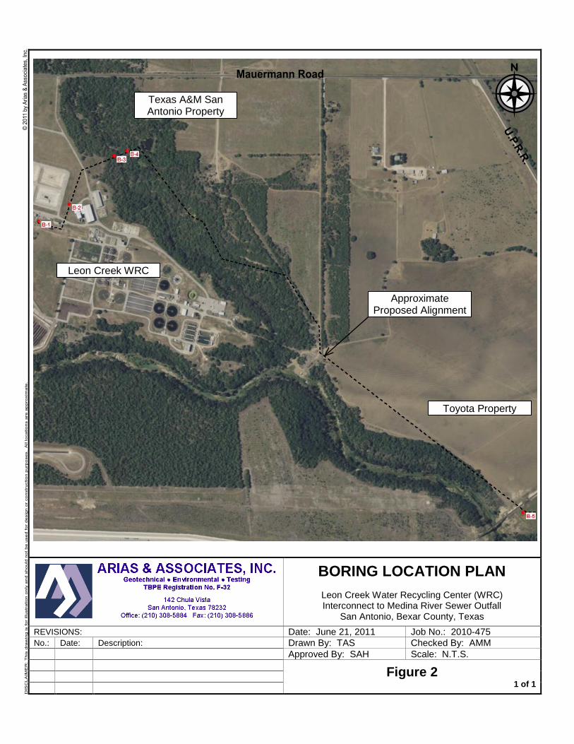
At the time of our field exploration, the project area varied from being well developed within
the Leon Creek WRC to an open farm field to a natural stream side that is heavily vegetated.
Site photographs are included in Appendix A of this report.
SOIL BORINGS AND LABORATORY TESTING
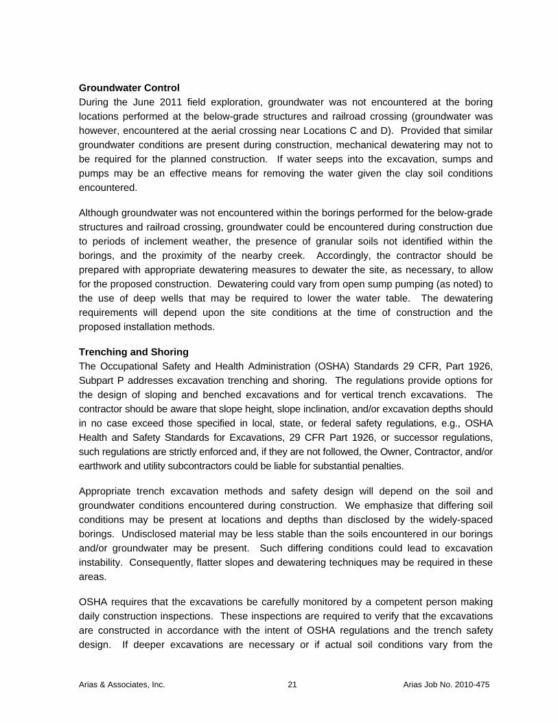
Five (5) soil borings were drilled at the approximate locations shown on the attached Boring
Location Plan included as Figure 2 in Appendix A. The borings were drilled to depths of
approximately 15 to 50 feet below the existing ground surface on June 17, 2011. The boring
depths were selected by CP&Y, Inc. based on the anticipated bearing depth of the proposed
project element. Drilling was performed in general accordance with ASTM D1586 and ASTM
D 1587 procedures for Split Spoon and Shelby Tube sampling techniques as described in
Appendix C. A truck-mounted drill rig using continuous flight augers together with the
sampling tools noted were used to secure the subsurface soil samples. After completion of
drilling, the boreholes were backfilled using cuttings generated during the drilling process.
Samples of encountered materials were obtained by: (1) using a split-barrel sampler while
performing the Standard Penetration Test (ASTM D 1586), (2) using a thin-walled tube
sampler (ASTM D 1587), and (3) by taking material from the auger as it was advanced
(ASTM D 1452). The sample depth interval and type of sampler used is included on the soil
boring log. Arias’ field representative visually logged each recovered sample and placed a
portion of the recovered sampled into a plastic bag for transport to our laboratory.
SPT N-values for those intervals where the sampler was advanced for a 12-inch penetration
after the initial 6-inch seating are shown on the individual boring logs included in Appendix B.
If the test was terminated during the 6-inch seating interval, or after 25 hammer blows were
applied where no advancement of the sampler was noted, the boring logs denote this
condition as blow count during seating penetration. Penetrometer readings recorded for thin-
walled tube samples that remained intact are also shown on the boring logs.
For each sample, Arias’ field representative visually classified the soil within the split-barrel
sampler and placed a portion into a plastic bag with zipper seal. The samples were then
placed into wax-coated cardboard sample boxes designed for transporting soil specimens to
the laboratory.
Subsequent to the drilling activities, ground surface elevations at the boring locations were
measured and provided to us by CP&Y, Inc. A summary of the boring number, general
location, corresponding project element, approximate ground surface elevation, approximate
boring termination depth and approximate bottom of pipe/structure at each of the boring
locations is provided in Table 1 below.

Arias & Associates, Inc. 7 Arias Job No. 2010-475
Table 1: Approximate Existing and Proposed Grades at New Structures
Boring No. General Location Description of Proposed
Structure Approximate
Ground Surface Elevation (ft)
Approximate Boring
Termination Elevation (ft)
Approximate Bottom of
Pipe/Structure (ft)
B-1 A – Leon Creek WRC
Expand Existing Flow Diversion Structure
541.6 (by survey) 526.6 533.5
B-2 B – Leon Creek WRC
New Flow Diversion Structure
529.5 (by survey) 505.5 515.25
B-3 C – Texas A&M Property
Aerial Pipeline Crossing over Comanche Creek,
West Side
526 (Note 2) 476 513.6
B-4 D – Texas A&M Property
Aerial Pipeline Crossing over Comanche Creek,
East Side
537 (Note 2) 488.5 513
B-5 E – Toyota Property
Directional Boring under Railroad
521 (Note 3) 496 507
Notes: 1. The topographic survey data and approximate ground surface elevations were provided by
CP&Y, Inc.
2. The approximate ground surface elevations for Locations C and D are assumed based on the Plan and Profile sheets provided by CP&Y, Inc. (Station 84+00 to 89+00, dated August 2011) and could vary from the actual locations. The approximate bottom of pipe/structure elevation shown for Locations C and D is in reference to the bottom of the diversion structure at the creek crossing.
3. Topographic survey data was not provided by CP&Y, Inc. for Location E (i.e., Boring B-5), therefore an approximate ground surface elevation was provided based on an existing topographic survey. The boring location is referenced from the ground surface where the boring was drilled and not at the top of the railroad track.
Soil classifications and borehole logging were conducted during the exploration by one of our
Engineering Technicians working under the supervision of the project Geotechnical
Engineer. Final soil classifications, as seen on the attached boring logs, were determined in
the laboratory based on laboratory and field test results and applicable ASTM procedures.
As a supplement to the field exploration, laboratory testing to determine soil water content,
Atterberg limits, and percent passing the US Standard No. 200 sieve was conducted. The
laboratory results are reported in the boring logs included in Appendix B. A key to the terms
and symbols used on the logs is also included in Appendix B. The soil laboratory testing for
this project was done in accordance applicable ASTM procedures with the specifications and
definitions for these tests listed in Appendix C.

Arias & Associates, Inc. 8 Arias Job No. 2010-475
Remaining soil samples recovered from this exploration will be routinely discarded following
submittal of this report.
SUBSURFACE CONDITIONS
Geology, generalized stratigraphy and groundwater conditions encountered at the project
site are discussed in the following sections. The subsurface and groundwater conditions are
based on conditions encountered at the boring locations to the depths explored.
Geology The earth materials underlying the project site have been regionally mapped as the alluvial
Terrace (Qt) deposits of Pleistocene age underlain by shallow marine or coastal deposits of
the Midway Formation (Emi) of Eocene age (approximately 36 to 56 million years before
present). The contact between the alluvial and shallow marine deposits represents a
significant erosional time gap which could be irregular with depth within the project area.
Locally, the materials encountered in the borings consist primarily of alluvial terrace soils
comprised of clays, gravelly clays and clayey gravels in a stiff to very hard and medium
dense condition. The underlying marine deposits consist of clays and claystone with
scattered iron oxide and gypsum deposits and are generally in a hard to very hard condition.
A Geologic Map is included as Figure 3 in Appendix A.
Generalized Site Stratigraphy and Engineering Properties The generalized stratigraphy and soil properties for the interpreted strata are summarized in
the following tables.
Table 2: Generalized Soil Conditions, Location A, Boring B-1
Stratum Approx. Elevation Depth, ft Material Type PI
range No. 200 range
N Range
I 541.6 to
537.6 0 to 4
LEAN CLAY (CL) trace gravel and calcareous deposits, dark brown and brown, very stiff to hard (possible fill)
26 88 23-27
II 537.6 to
533.6 4 to 8
LEAN CLAY (CL) trace calcareous deposits, light brown, hard
23 -- 32-39
III 533.6 to
526.6 8 to 15 LEAN CLAY (CL), tan, hard 19-27 91 28-42
Where: Depth - Depth from existing ground surface during geotechnical study, feet PI - Plasticity Index, % No. 200 - Percent passing #200 sieve, % N - Standard Penetration Test (SPT) value, blows per foot PP - Pocket Penetrometer (PP), tons per square foot
Notes: 1. Elevations provided by CP&Y, Inc.

Arias & Associates, Inc. 9 Arias Job No. 2010-475
Table 3: Generalized Soil Conditions, Location B, Boring B-2
Stratum Approx. Elevation Depth, ft Material Type PI
range No. 200 range
PP range
N Range
FILL 529.5 to
526 0 to 3.5
LEAN CLAY (CL) with sand and trace gravel, dark brown to brown, very stiff
to hard 27 -- 24-32
I 526 to 521.5
3.5 to 8 FAT CLAY (CH) dark brown to black,
hard 33 95 -- 28-34
II 521.5 to
516.5 8 to 13
LEAN CLAY (CL) with calcareous deposits, light brown, very hard
28 92 4.5+ --
III 516.5 to
505.5 13 to 24
LEAN CLAY (CL) with calcareous deposits, tan, very stiff to hard
19 -- 3.75-4.5
32
Notes: 1. Elevations provided by CP&Y, Inc.
Table 4: Generalized Soil Conditions, West Side of Comanche Creek, Location C, Boring B-3
Stratum Approx. Elevation Depth, ft Material Type PI
range No. 200 range
PP range
N Range
I 526 to 516 0 to 10 FAT CLAY (CH) very dark brown to
dark brown, stiff to very hard 32-36 95 4.5+ 9-26
II 516 to 501 10 to 25 LEAN CLAY (CL) with sand and
gypsum crystals, light brown, hard to very hard
26 82 4.25-4.5+
35
IIb 501 to 494 25 to 32 Clayey GRAVEL (GC) with sand, tan,
medium dense 34 40 -- 24
III 494 to 477.5
32 to 48.5
FAT CLAY (CH) with gravel, tan, very stiff to hard
42 94 -- 25-36
IV 477.5 to
476 48.5 to
50 CLAYSTONE with iron oxide seams,
gray, very hard -- -- -- 72
Notes: 1. Elevations provided by CP&Y, Inc.
2. The Stratum IIb Clayey GRAVEL (GC) was only observed at this location.

Arias & Associates, Inc. 10 Arias Job No. 2010-475
Table 5: Generalized Soil Conditions, East Side of Comanche Creek, Location D, Boring B-4
Stratum Approx. Elevation Depth, ft Material Type PI
range No. 200 range
PP range
N Range
I 537 to 533 0 to 4 Gravelly FAT CLAY (CH) with sand,
brown, stiff to very stiff 28 59 -- 13-23
III 533 to 497 4 to 40 FAT CLAY (CH) with iron oxide
seams, tan and gray, very stiff to very hard
30-41 96-97 4.5+ 20-77
IV 497 to 488.5
40 to 48.5
CLAYSTONE with cemented seams, gray, very hard
-- -- -- >100
Notes: 1. Elevations provided by CP&Y, Inc.
2. The Stratum II light brown, LEAN CLAY (CL) was not observed at this location.
Table 6: Generalized Soil Conditions, Location E, Boring B-5
Stratum Approx. Elevation Depth, ft Material Type PI
range No. 200 range
PP range
N Range
I 521 to 509 0 to 12 LEAN CLAY (CL) with sand, brown,
stiff to hard 22 82-88 4.5+ 12-15
III 509 to 486 12 to 25 LEAN CLAY (CL) tan, hard 27 -- 3.25-3.75
--
Notes: 1. Elevations provided by CP&Y, Inc.
2. The Stratum II light brown, LEAN CLAY (CL) was not observed at this location.
Groundwater A dry soil sampling method was used to obtain the soil samples at the project site.
Groundwater was observed within one of the five borings during the soil sampling activities
which were performed on June 17, 2011. The borings were left open for an approximate 24-
hour period in order to obtain delayed groundwater readings and the depth to
caving/sloughing. Groundwater observations made during drilling and following an
approximate 24-hour period are noted on the individual borings logs and summarized in
Table 7.
It should be noted that water levels in open boreholes may require several hours to several
days to stabilize depending on the permeability of the soils. Groundwater levels at this site
may be subject to seasonal conditions, recent rainfall, drought or temperature affects.
Groundwater conditions may vary during construction from the conditions encountered in our

Arias & Associates, Inc. 11 Arias Job No. 2010-475
soil borings. Importantly, South Texas, including the area of the project site, is currently
experiencing drought conditions.
Table 7: Summary of the Groundwater Observations at Boring Locations
Boring No.
General Location
Approximate Ground Surface
Elevation (ft)
Depth to Groundwater
During Drilling Operations (ft)
Depth to Groundwater Observed After a 24-
hour delay (ft)
Approximate Groundwater Elevation (ft)
B-1 A – Leon Creek WRC
541.6 (by survey)
Not Observed Backfilled upon Completion
n/a
B-2 B – Leon Creek WRC
529.5 (by survey)
Not Observed Backfilled upon Completion
n/a
B-3 C – Texas A&M Property
526 (Note 2) 32 26 (Borehole caved at ~28.5 ft)
~500
B-4 D – Texas A&M Property
537 (Note 2) Not Observed 39.4 (Borehole caved
at ~44.2 ft)
~497.6
B-5 E – Toyota Property
521 (Note 3) Not Observed Backfilled upon Completion
n/a
Notes: 1. The topographic survey data and approximate ground surface elevations were provided by
CP&Y, Inc.
2. The approximate ground surface elevations for Locations C and D are assumed based on the Plan and Profile sheets provided by CP&Y, Inc. (Station 84+00 to 89+00, dated August 2011) and could vary from the actual locations. The approximate bottom of pipe/structure elevation shown for Locations C and D is in reference to the bottom of the diversion structure at the creek crossing.
3. Topographic survey data was not provided by CP&Y, Inc. for Location E (i.e., Boring B-5), therefore an approximate ground surface elevation was provided based on an existing topographic survey. The boring location is referenced from the ground surface where the boring was drilled and not at the top of the railroad track.
4. Groundwater measurements were recorded during field exploration on July 17, 2011. Delayed groundwater measurements were recorded following an approximate 24-hour period.
Clay soils are generally not conducive to the presence of groundwater; however, pockets or
seams of gravels, sands, silts or open fractures and joints can store and transmit “perched”
groundwater flow or seepage. The gravelly and sandy soils encountered within the borings
can store and transmit “perched” groundwater flow or seepage. Perched groundwater
seepage can also occur within joints and factures or at strata interfaces, particularly
clay/gravel, or soil/claystone interfaces. Seasonal weather conditions or other factors may
dictate actual shallow groundwater conditions at the time of construction.

Arias & Associates, Inc. 12 Arias Job No. 2010-475
The installation of temporary piezometers (observation wells) can be performed to obtain
more accurate groundwater data. Additionally, pump and recharge tests can be performed
using the piezometers to aid in estimating groundwater seepage rates. Subsurface water
readings and seepage rates will generally provide an indication of groundwater conditions at
that respective location and time. If needed, this information can be used to assist the
contractor in developing construction dewatering plans. We should note that installing
piezometers and performing groundwater testing was beyond our authorized scope of
services for this project. We can provide these services if desired.
AERIAL CROSSING FOUNDATION RECOMMENDATIONS
The type of foundation most appropriate for a given structure depends on several factors: (1)
the function of the structure and the loads it may carry, (2) the subsurface conditions, and (3)
the cost of the foundation in comparison with the cost of the superstructure. In addition, the
performance criteria for the structure are significant relative to the foundation system
selected.
We have been informed by CP&Y, Inc. that it is desired to utilize straight-shaft drilled piers to
support the proposed aerial crossing over Comanche Creek (i.e., structure corresponding to
Locations C and D). The piers when properly founded can help reduce foundation
movement of the superstructure. Geotechnical design criteria for this foundation type in
consideration of the site’s expansive soil conditions are presented herein.
Expansive Soil Considerations Structural damage can be caused by volume changes in clay soils. Clays can shrink when
they lose water and swell (grow in volume) when they gain water. The potential of expansive
clays to shrink and swell is typically related to the Plasticity Index (PI). Clays with a higher PI
generally have a greater potential for soil volume changes due to moisture content variations.
The soils found at this site are capable of swelling and shrinking in volume dependent on
potentially changing soil water content conditions during or after construction. The term
swelling soils implies not only the tendency to increase in volume when water is available,
but also to decrease in volume or shrink if water is removed. Considering the plasticity of the
site soils, these soils would have a moderate to high swell potential upon future changes in
soil moisture content.
Several methods exist to evaluate swell potential of expansive clay soils. We have estimated
potential heave for this site utilizing the TXDOT method (Tex 124-E). Using the TXDOT
method, we estimate that the PVR is approximately 2 to 4½ inches at this site considering
the existing soil moisture conditions at the time of the sampling activities. This is a soil heave
magnitude considering a change from a dry to wet soil moisture condition within the active
zone due to climate variations.
Arias & Associates, Inc. 13 Arias Job No. 2010-475
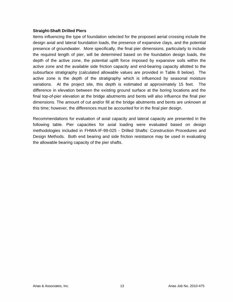
Straight-Shaft Drilled Piers Items influencing the type of foundation selected for the proposed aerial crossing include the
design axial and lateral foundation loads, the presence of expansive clays, and the potential
presence of groundwater. More specifically, the final pier dimensions, particularly to include
the required length of pier, will be determined based on the foundation design loads, the
depth of the active zone, the potential uplift force imposed by expansive soils within the
active zone and the available side friction capacity and end-bearing capacity allotted to the
subsurface stratigraphy (calculated allowable values are provided in Table 8 below). The
active zone is the depth of the stratigraphy which is influenced by seasonal moisture
variations. At the project site, this depth is estimated at approximately 15 feet. The
difference in elevation between the existing ground surface at the boring locations and the
final top-of-pier elevation at the bridge abutments and bents will also influence the final pier
dimensions. The amount of cut and/or fill at the bridge abutments and bents are unknown at
this time; however, the differences must be accounted for in the final pier design.
Recommendations for evaluation of axial capacity and lateral capacity are presented in the
following table. Pier capacities for axial loading were evaluated based on design
methodologies included in FHWA-IF-99-025 - Drilled Shafts: Construction Procedures and
Design Methods. Both end bearing and side friction resistance may be used in evaluating
the allowable bearing capacity of the pier shafts.

Arias & Associates, Inc. 14 Arias Job No. 2010-475
Table 8: Drilled Pier Axial Design Parameters for Aerial Crossing, Location C and D– Axial Capacity
Depth Approximate Elevation (ft) Material
Recommended Design Parameters
Allowable Skin Friction,
psf (αc/FS)
Allowable End Bearing,
psf (cNc/FS)
Uplift Force, kips
West Bridge Abutment, Location C, Boring B-3
0 to 5 526 to 521 FAT CLAY (CH) Neglect Contribution
5 to 15 521 to 511 FAT CLAY (CH) and
LEAN CLAY (CL) 700 --
65D
15 to 25 511 to 501 LEAN CLAY (CL) 750 --
25 to 38 501 to 488 CLAYEY GRAVEL (GC) and LEAN CLAY (CL)
800 12,000
38 to 48.5 488 to 477.5 FAT CLAY (CH) 1,250 15,000
48.5 to 50 477.5 to 476 CLAYSTONE 1,600 24,000
East Bridge Abutment, Location D, Boring B-4
0 to 5 537 to 532 FAT CLAY (CH) Neglect Contribution
5 to 15 532 to 522 FAT CLAY (CH) 700 --
75D 15 to 25 522 to 512 FAT CLAY (CH) 800 --
25 to 40 512 to 497 FAT CLAY (CH) 1,250 15,000
40 to 50 497 to 488.5 CLAYSTONE 1,600 24,000
Constraints to be Imposed During Pier Design
Minimum embedment depth 30 feet below existing ground surface (June 2011)
Minimum shaft diameter 24 inches

Arias & Associates, Inc. 15 Arias Job No. 2010-475
Notes: 1. Topographic survey information was provided by CP&Y, Inc.
2. For straight shaft piers, the contribution of the soils for the top 5 feet of soil embedment and for a length equal to at least 1 pier diameter from the bottom of the shaft should be neglected in determination of friction capacity. The recommended design parameters include a factor of safety of 2 for skin friction and of 3 for end bearing.
3. The uplift force resulting from expansion of soils in the active zone may be computed using the above formula where D is the shaft diameter in feet. For drilled straight-sided piers, the contribution from soils to resist uplift is the allowable skin friction resistance of the soils below the 15-foot deep estimated active zone. Sustained dead loads will also aid in resisting uplift forces. Pier depths greater than 30 feet may be required to resist expansive soil uplift forces.
4. The minimum embedment depth was selected to locate the pier base below the depth of seasonal moisture change and within a specified desired bearing stratum. Pier vertical reinforcing steel should be designed to resist the uplift forces from swelling soils. A minimum of 1% of the gross cross-sectional area should be considered and the final reinforcing requirements should be determined by the project structural engineer. Tensile rebar steel should be designed in accordance with ACI Code Requirements.
5. Total and differential settlement of piers is expected to be less than 1 inch and 0.5 inch, respectively. Estimated settlements are based on performance of properly installed piers in the San Antonio metropolitan area. A detailed settlement estimate is outside of the scope of this service.
6. If the piers are subject to water action, scour may occur. If this is the case, the pier length should be referenced from the level of the maximum scour depth. Likewise, the Lpile analysis should neglect the contribution of soils down to the maximum scour depth. The grain size analysis curve for the sample retrieved within the creek area is included in Appendix D.
Since groundwater (Borings B-3 and B-4) and granular soils (Boring B-3) were present within
the borings performed at the proposed bridge crossing, we anticipate that the construction of
piers which extend below this depth range will require either: (1) the temporary casing
method should the tip of the pier excavation and casing be extended, as necessary, in a
relatively impervious clay stratum to adequately seal the drill hole from the excessive influx of
groundwater, or (2) the slurry displacement method should the pier tip bear within water-
bearing strata and/or if an adequate casing seal cannot be established. The presence and location of groundwater and potentially caving soils should be confirmed before construction commences. It should be noted that high-torque drilling equipment capable of drilling in rock would be required at this site due to the very hard and dry clay, claystone, and dense gravel encountered during the drilling operations. Drilled pier installation considerations are
discussed further in Table 10.
Lateral pile analyses including capacity, maximum shear, and maximum bending moment
should be evaluated by the project structural engineer using LPILE or similar software. In the
following table, Arias presents geotechnical input parameters for the encountered soils.
Please note that the depths to the top and bottom of each layer were interpreted using
approximate elevation data at the explored boring locations and layer boundaries as shown
on the boring logs.

Arias & Associates, Inc. 16 Arias Job No. 2010-475
Table 9: Drilled Pier Geotechnical Input Parameters for LPILE Analyses – Aerial Crossing, Location C and D
Depth (ft) Approximate Elevation (ft)
Material γe Cu φ K (cyclic loading) e50
West Bridge Abutment, Location C, Boring B-3
0 to 5 526 to 521 FAT CLAY (CH) Neglect Contribution
5 to 15 521 to 511 FAT CLAY (CH) and
LEAN CLAY (CL) 120 3,000 0 400 0.005
15 to 25 511 to 501 LEAN CLAY (CL) 125 3,500 0 400 0.005
25 to 38 501 to 488 CLAYEY GRAVEL
(GC) and LEAN CLAY (CL)
63 4,000 0 400 0.005
38 to 48.5 488 to 477.5 FAT CLAY (CH) 63 5,000 0 800 0.004
48.5 to 50 477.5 to 476 CLAYSTONE 68 8,000 0 800 0.004
East Bridge Abutment, Location D, Boring B-4
0 to 5 537 to 532 FAT CLAY (CH) Neglect Contribution
5 to 15 532 to 522 FAT CLAY (CH) 120 3,000 0 400 0.005
15 to 25 522 to 512 FAT CLAY (CH) 125 4,000 0 400 0.005
25 to 40 512 to 497 FAT CLAY (CH) 63 5,000 0 800 0.004
40 to 50 497 to 488.5 CLAYSTONE 68 8,000 0 800 0.004
Where: γe = effective soil unit weight, pcf cu = undrained soil shear strength, psf
φ = undrained angle of internal friction, degrees K = modulus of subgrade reaction, pci e50 = 50% strain value
Design depth to groundwater is 26 feet based on boring data

Arias & Associates, Inc. 17 Arias Job No. 2010-475
Drilled Piers Construction Considerations The contractor should verify groundwater conditions before production pier installation
begins. Comments pertaining to high-torque drilling equipment, groundwater, slurry, and
temporary casing are based on generalized conditions encountered at the explored
locations. Conditions at individual pier locations may differ from those presented and may
require that these issues be implemented to successfully install piers. Construction
considerations for drilled pier foundations are outlined in the following table.
Table 10: Drilled Pier Installation Considerations for Locations C and D
Recommended installation procedure USACE refers to FHWA (FHWA-NHI-10-016, May 2010)
High-torque drilling equipment anticipated Yes
Groundwater anticipated
Yes; groundwater observed at 32 feet during sampling activities; delayed groundwater
measured at 26 to 39 feet below the existing ground surface at the time of the field exploration
Temporary casing anticipated Yes
Slurry installation anticipated Yes, if casing seal into relatively impervious clay soil cannot be achieved
Concrete placement Same day as drilling
Maximum water accumulation in excavation 2 inches
Concrete installation method needed if water accumulates
Tremie or pump to displace water
Quality assurance monitoring
Geotechnical engineer’s representative should be present during drilling of all piers, should observe drilling and document the installed depth, should
confirm bearing material type at the base of excavation and cleanliness of base, should
observe placement of reinforcing steel
The following installation techniques will aid in successful construction of the shafts:
• The clear spacing between rebar or behind the rebar cage should be at least 3 times
the maximum size of coarse aggregate.
• Centralizers on the rebar cage should be installed to keep the cage properly
positioned.
• Cross-bracing of a reinforcing cage may be used when fabricating, transporting,
and/or lifting. However, experience has shown that cross-bracing can contribute to
the development of voids in a concrete shaft. Therefore, we recommend the removal
of the cross-bracing prior to lowering the cage in the open shaft.
Arias & Associates, Inc. 18 Arias Job No. 2010-475
• The use of a tremie should be employed so that concrete is directed in a controlled
manner down the center of the shaft to the shaft bottom. The concrete should not be
allowed to ricochet off the pier reinforcing steel nor off the pier side walls.
• The pier concrete should be designed to achieve the desired design strength when
placed at a 7-inch slump, plus or minus 1-inch tolerance. Adding water to a mix
designed for a lower slump does not meet these recommendations.
Arias should be given the opportunity to review the proposed specifications prior to
construction.
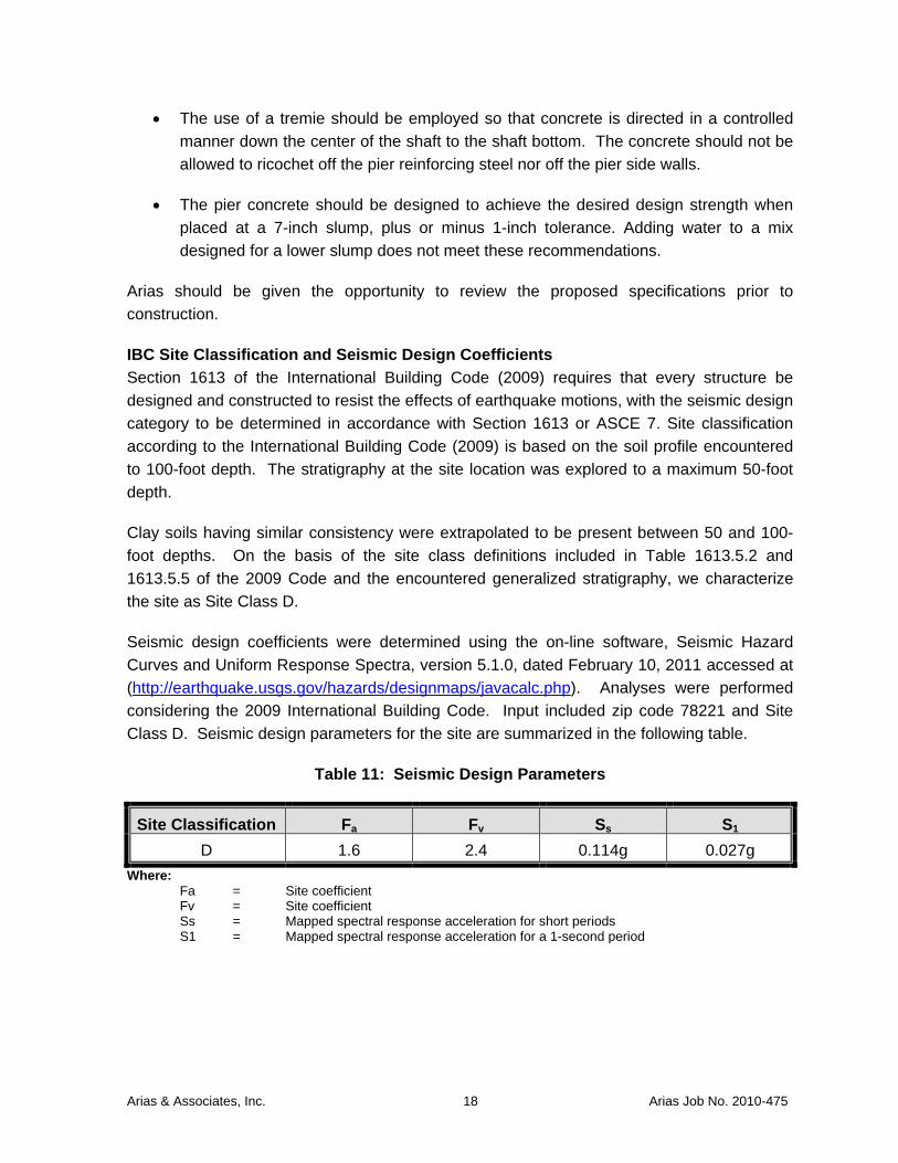
IBC Site Classification and Seismic Design Coefficients Section 1613 of the International Building Code (2009) requires that every structure be
designed and constructed to resist the effects of earthquake motions, with the seismic design
category to be determined in accordance with Section 1613 or ASCE 7. Site classification
according to the International Building Code (2009) is based on the soil profile encountered
to 100-foot depth. The stratigraphy at the site location was explored to a maximum 50-foot
depth.
Clay soils having similar consistency were extrapolated to be present between 50 and 100-
foot depths. On the basis of the site class definitions included in Table 1613.5.2 and
1613.5.5 of the 2009 Code and the encountered generalized stratigraphy, we characterize
the site as Site Class D.
Seismic design coefficients were determined using the on-line software, Seismic Hazard
Curves and Uniform Response Spectra, version 5.1.0, dated February 10, 2011 accessed at
(http://earthquake.usgs.gov/hazards/designmaps/javacalc.php). Analyses were performed
considering the 2009 International Building Code. Input included zip code 78221 and Site
Class D. Seismic design parameters for the site are summarized in the following table.
Table 11: Seismic Design Parameters
Site Classification Fa Fv Ss S1 D 1.6 2.4 0.114g 0.027g
Where: Fa = Site coefficient Fv = Site coefficient Ss = Mapped spectral response acceleration for short periods S1 = Mapped spectral response acceleration for a 1-second period

Arias & Associates, Inc. 19 Arias Job No. 2010-475
BELOW GRADE STRUCTURES AND PIPELINE DESIGN CONSIDERATIONS
Details regarding excavation, dewatering, site safety, shoring and excavation retention,
selection of machinery and equipment, and benching and sloping requirements are
considered construction means and methods to accomplish the work, and thus, are the sole
responsibility of the Contractor. The information presented herein pertaining to groundwater
control and trenching and shoring is for informational purposes only. Additional information
should be collected by the Contractor, as they deem appropriate.
We understand that below grade structures and utilities are planned to include: (1) Location
A – expand existing concrete diversion structure, (2) Location B – install new diversion
structure for FEB drain line and (3) Location E – trenchless installation methods along
existing railroad near the Toyota property. The net allowable bearing pressure at each of the
proposed structure locations is provided below based on the results of the soil borings and the
approximate elevations provided.
Table 12: Recommended Allowable Bearing Pressure for Drainage Structures
Boring No.
General Location
Approximate Ground Surface
Elevation (ft)
Approximate Boring
Termination Elevation (ft)
Approximate Bottom of
Pipe/Structure (ft)
Anticipated Bearing Surface
Net Allowable Bearing
Pressure (psf)
B-1 A – Leon
Creek WRC
541.6 (by survey) 527 533.5
Tan LEAN CLAY (CL), hard
4,000
B-2 B – Leon
Creek WRC
529.5 (by survey)
505.5 515.25 Tan LEAN CLAY (CL), hard
4,000
B-5 E –
Toyota Property
521 (Note 2) 496 507 Tan LEAN CLAY (CL), hard
4,000
Notes: 1. The topographic survey data and approximate ground surface elevations were provided by
CP&Y, Inc.
2. Topographic survey data was not provided by CP&Y, Inc. for Location E (i.e., Boring B-5), therefore an approximate ground surface elevation was provided based on an existing topographic survey. The boring location is referenced from the ground surface where the boring was drilled and not at the top of the railroad track.
Trenchless Technology Considerations Based on the information provided by CP&Y, Inc., we understand that trenchless boring
methods will be utilized at Location E along the existing railroad near the Toyota Property.
We understand that open-cut methods will be employed at all other structure locations.

Arias & Associates, Inc. 20 Arias Job No. 2010-475
Trenchless methods may include directional boring techniques or micro-tunneling and pipe-
jacking techniques. These methods will be employed to install the pipe below and across the
crossing. The size of the pipe and pipe flexibility will often determine what trenchless
construction technique will be selected. Our experience is that directional boring techniques
are often selected when more flexible, smaller diameter pipes are being installed. If
directional boring techniques cannot be accomplished, then micro-tunneling and pipe-jacking
may be the more feasible installation method.
The proposed boring depth is anticipated to be near the 15 foot depth but has not been
finalized at this time. For roadway crossings, according to Special Provisions for TxDOT –
San Antonio District Utility Permits, Revised December 5, 2003, Paragraph 6, Open
Trenching or Boring Operations for Utility Work and Paragraph 8 Boring and Jacking and The
San Antonio District Minimum Depth of Cover Table dated April 4, 2002, the depth of
horizontal earth boring operations should be a minimum of 10 feet (minimum cover over the
steel casing) below pavement section and 10 feet beyond the edge of the pavement at a
given area. It is also recommended that this minimum depth guideline be used for the
railroad crossing.
It is recommended that the Contractor review the boring logs prior to performing trenchless
boring operations. The boring logs and Table 14 include our interpreted geotechnical design
parameters typically used for trenchless technology. The information included herein
indicates the soil consistency at the time of exploration, soil strength (SPT value,
Penetrometer value), undrained cohesion (C, shear strength), φ value (angle of internal
friction), applicable coefficient of active and passive soil pressures (Ka and Kp), and effective
soil unit weight (γ’). The soil design parameters as presented in the referenced table are
meant to supplement the Boring Logs to provide general baseline information of the
anticipated geotechnical conditions and constructability issues in constructing the pipeline,
which bidders should take into consideration. The purpose of this report is not intended as a sole reliance for bid development; additional studies may be required to reduce the risk of unanticipated conditions. The soil parameters provided in this report can be used to assess temporary pipe installation
techniques. That is, temporary access pits should be designed to consider the short-term
lateral earth pressures and base stability. The soil parameters can be used to calculate
estimated lateral earth pressures for the short-term construction condition. Furthermore, the
soil parameters can be used to assess the passive resistance of a reaction block or anchor
associated with pipe-jacking. A factor of safety of at least 2 should be used for a short-term
passive resistance condition.
Arias & Associates, Inc. 21 Arias Job No. 2010-475
Groundwater Control During the June 2011 field exploration, groundwater was not encountered at the boring
locations performed at the below-grade structures and railroad crossing (groundwater was
however, encountered at the aerial crossing near Locations C and D). Provided that similar
groundwater conditions are present during construction, mechanical dewatering may not to
be required for the planned construction. If water seeps into the excavation, sumps and
pumps may be an effective means for removing the water given the clay soil conditions
encountered.
Although groundwater was not encountered within the borings performed for the below-grade
structures and railroad crossing, groundwater could be encountered during construction due
to periods of inclement weather, the presence of granular soils not identified within the
borings, and the proximity of the nearby creek. Accordingly, the contractor should be
prepared with appropriate dewatering measures to dewater the site, as necessary, to allow
for the proposed construction. Dewatering could vary from open sump pumping (as noted) to
the use of deep wells that may be required to lower the water table. The dewatering
requirements will depend upon the site conditions at the time of construction and the
proposed installation methods.
Trenching and Shoring The Occupational Safety and Health Administration (OSHA) Standards 29 CFR, Part 1926,
Subpart P addresses excavation trenching and shoring. The regulations provide options for
the design of sloping and benched excavations and for vertical trench excavations. The
contractor should be aware that slope height, slope inclination, and/or excavation depths should
in no case exceed those specified in local, state, or federal safety regulations, e.g., OSHA
Health and Safety Standards for Excavations, 29 CFR Part 1926, or successor regulations,
such regulations are strictly enforced and, if they are not followed, the Owner, Contractor, and/or
earthwork and utility subcontractors could be liable for substantial penalties.
Appropriate trench excavation methods and safety design will depend on the soil and
groundwater conditions encountered during construction. We emphasize that differing soil
conditions may be present at locations and depths than disclosed by the widely-spaced
borings. Undisclosed material may be less stable than the soils encountered in our borings
and/or groundwater may be present. Such differing conditions could lead to excavation
instability. Consequently, flatter slopes and dewatering techniques may be required in these
areas.
OSHA requires that the excavations be carefully monitored by a competent person making
daily construction inspections. These inspections are required to verify that the excavations
are constructed in accordance with the intent of OSHA regulations and the trench safety
design. If deeper excavations are necessary or if actual soil conditions vary from the

Arias & Associates, Inc. 22 Arias Job No. 2010-475
borings, the trench safety design should be reviewed and revisions should be made to the
design as needed based on encountered conditions. The effects of changed weather
conditions, surcharge loadings, and cuts into adjacent backfills of existing utilities are critical
items that should be evaluated by the inspector. The flow of water into the base and sides of
the excavation and the presence of any surface slope cracks should also be carefully
monitored by the Trench Safety Engineer.
Regardless of excavation depth, we recommend that all vehicles and material stockpiles be
located at distance equal to or preferably greater than the trench vertical height. The trench
safety design should consider the impacts of surcharge loads that may result from the
presence of material stockpiles, equipment traffic, and other loadings in close proximity to the
trench.
OSHA Soil Classifications For access pits and open-cut excavations, OSHA regulations must be followed concerning
temporary allowable slopes. The contractor should be aware that slope height, slope
inclination, or excavation depths (including utility trench excavations) should in no case
exceed those specified in local, state, or federal safety regulations, e.g., OSHA Health and
Safety Standards for Excavations, 29 CFR Part 1926, dated October 31, 1989. Such
regulations are strictly enforced and, if not followed, the Owner, Contractor, and/or earthwork
and utility subcontractors could be liable for substantial penalties. The soils encountered at
this site were classified as to type in accordance with this publication and are shown in the
table below.
Table 13: OSHA Soil Classifications
Stratum Description OSHA Classification
I Dark Brown to Brown, CLAY (CH-CL) B
II Light Brown, LEAN CLAY (CL) B
IIb Clayey GRAVEL (GC) C
III Tan and Gray, CLAY (CH-CL) C
IV Gray, CLAYSTONE B or C
**It must be noted that layered slopes cannot be steeper at the top than the underlying slope and that all materials that become wet or are situated below the water table must be classified as Type “C” soils. The OSHA publication should be referenced for layered soil conditions, benching, etc.** For excavations less than 20 feet deep, the maximum allowable slope for Type “C” soils is
1.5H:1V (34°), for Type “B” soils is 1H:1V (45°) and for Type “A” soils is ¾H:1V (53°). It
should be noted that the table and allowable slopes above are for temporary slopes.

Arias & Associates, Inc. 23 Arias Job No. 2010-475
Lateral Earth Pressures Lateral earth pressures for design of temporary trench shoring and permanent below grade
structures can be assessed utilizing the soil design parameters provided in the following table.
Active earth pressure can be used to assess temporary trench shoring. At rest earth pressure
should be used to assess permanently buried structures.
Table 14: Lateral Earth Pressure Parameters
Stratum Description
Soil Unit
Weight, γe
Undrained Conditions
Drained Conditions ka kp* ko
C φ C’ φ’
I CLAY (CH-CL) 125 1,000 0 0 17 0.55 1.8 0.71
II LEAN CLAY (CL) 125 1,500 0 0 19 0.50 2.0 0.68
IIb Clayey GRAVEL
(GC) 125 0 26 0 26 0.39 2.6 0.56
III CLAY (CH) 125 2,000 0 0 17 0.55 1.8 0.71
IV CLAYSTONE 125 5,000 0 0 17 0.55 1.8 0.71
where: γe = effective soil unit weight, pcf
C = undrained soil shear strength, psf
φ = angle of internal friction, deg.
C’ = drained soil shear strength, psf
φ’ = effective stress angle of internal friction, deg.
ka = coefficient of active earth pressure
kp = coefficient of passive earth pressure
ko = coefficient of at-rest earth pressure
* = These are ultimate passive earth pressure coefficients. A factor of safety of at least 2
should be applied when determining passive resistance.
Short-term lateral earth pressures on the trench shoring can be calculated considering a
rectangular pressure diagram having a magnitude of:
(γ)(H)(ka)
where γ and ka are provided above and H is the depth of excavation in feet. Any surcharge
loads including equipment loads, and soil stockpiles and hydrostatic pressures should be
added to this value as required.

Arias & Associates, Inc. 24 Arias Job No. 2010-475
GENERAL COMMENTS
This report was prepared as an instrument of service for this project exclusively for the use of
CP&Y, Inc., Inc. and the project design team. If the development plans change relative to
the proposed construction or anticipated loading conditions, or if different subsurface
conditions are encountered, we should be informed and retained to ascertain the impact of
these changes on our recommendations. We cannot be responsible for the potential impact
of these changes if we are not informed.
Review Arias should be given the opportunity to review the design and construction documents. The
purpose of this review is to check to see if our recommendations are properly interpreted into
the project plans and specifications. Please note that design review was not included in the
authorized scope and additional fees may apply.
Quality Assurance Testing The long-term success of the project will be affected by the quality of materials used for
construction and the adherence of the construction to the project plans and specifications.
As Geotechnical Engineer of Record, we should be engaged by the Owner to provide quality
assurance testing. Our services, as a minimum, will be to observe and confirm that the
encountered materials during earthwork for site subgrade improvement and pipeline
installation are consistent with those encountered during this study. We also should verify
that the materials used as part of subgrade improvement, pipeline installation, and other
pertinent elements conform to the project specifications and that placement of these
materials is in conformance with the specifications. With regard to drilled pier construction,
we should be engaged to observe and evaluate the foundation installation to determine that
the actual bearing materials are consistent with those encountered during the field
exploration and to observe and document the pier installation process. In the event that
Arias is not retained to provide quality assurance testing, we should be immediately
contacted if differing subsurface conditions are encountered during construction. Differing
materials may require modification to the recommendations that we provided herein.
Subsurface Variations Soil and groundwater conditions may vary away from the sample boring locations. Transition
boundaries or contacts, noted on the boring logs to separate soil types, are approximate.
Actual contacts may be gradual and vary at different locations. The contractor should verify
that similar conditions exist throughout the proposed area of excavation. If different
subsurface conditions or highly variable subsurface conditions are encountered during
construction, we should be contacted to evaluate the significance of the changed conditions
relative to our recommendations.

Arias & Associates, Inc. 25 Arias Job No. 2010-475
Standard of Care This report has been prepared in accordance with generally accepted geotechnical
engineering practice with a degree of care and skill ordinarily exercised by reputable
geotechnical engineers practicing in this area and the area of the site.

Arias & Associates, Inc. A-1 Arias Job No. 2010-475
APPENDIX A: FIGURES AND SITE PHOTOGRAPHS

VICINITY MAP
Leon Creek Water Recycling Center (WRC) Interconnect to Medina River Sewer Outfall
San Antonio, Bexar County, Texas
Date: June 21, 2011 Job No.: 2010-475 Figure 1 1 of 1
Drawn By: TAS Checked By: AMM
Approved By: SAH Scale: N.T.S.
Approximate Site Limits
BORING LOCATION PLAN
Leon Creek Water Recycling Center (WRC) Interconnect to Medina River Sewer Outfall
San Antonio, Bexar County, Texas REVISIONS: Date: June 21, 2011 Job No.: 2010-475 No.: Date: Description: Drawn By: TAS Checked By: AMM
Approved By: SAH Scale: N.T.S.
Figure 2 1 of 1
Leon Creek WRC
Toyota Property
Texas A&M San Antonio Property
Approximate Proposed Alignment

PORTION OF GEOLOGIC ATLAS OF TEXAS
LEGEND
Symbol Name Age Qal Active Alluvial Deposits Quaternary Period / Holocene Epoch Qt Alluvial Terrace Deposits Quaternary Period / Pleistocene Epoch Qle Leona Formation (Alluvium) Quaternary Period / Pleistocene Epoch Q-Tu Uvalde Gravel Formation Quaternary – Tertiary Periods Ec Carrizo Sand Formation Tertiary Period / Eocene Epoch Ewi Wilcox Formation Tertiary Period / Eocene Epoch Emi Midway Formation Tertiary Period / Eocene Epoch Fault Segment with Indication of Relative Movement
GEOLOGIC MAP
Proposed Leon Creek Water Recycling Center (WRC) Mauerman Road
City of San Antonio, Bexar County, TX
Date: June 27, 2011 Job No.: 2010-475 Figure 3 1 of 1
Drawn By: JLK Checked By: AMM Approved By: SAH Scale: N.T.S.
U D
ESTIMATED PROJECT LOCATION
Qal
Ec

Photo 1: Looking towards Boring B-1
Photo 2: Looking towards Boring B-2
SITE PHOTOS
Leon Creek Water Recycling Center (WRC) Interconnect to Medina River Sewer Outfall
San Antonio, Bexar County, Texas
Date: June 22, 2011 Job No.: 2010-475 Appendix A 1 of 3
Drawn By: TAS Checked By: AMM Approved By: SAH Scale: N.T.S.
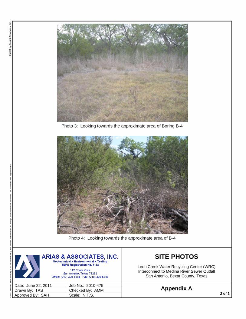
Photo 3: Looking towards the approximate area of Boring B-4
Photo 4: Looking towards the approximate area of B-4
SITE PHOTOS
Leon Creek Water Recycling Center (WRC) Interconnect to Medina River Sewer Outfall
San Antonio, Bexar County, Texas
Date: June 22, 2011 Job No.: 2010-475 Appendix A 2 of 3
Drawn By: TAS Checked By: AMM Approved By: SAH Scale: N.T.S.

Photo 5: Looking at the area of Boring B-5
SITE PHOTOS
Leon Creek Water Recycling Center (WRC) Interconnect to Medina River Sewer Outfall
San Antonio, Bexar County, Texas
Date: June 22, 2011 Job No.: 2010-475 Appendix A 3 of 3
Drawn By: TAS Checked By: AMM Approved By: SAH Scale: N.T.S.

Arias & Associates, Inc. B-1 Arias Job No. 2010-475
APPENDIX B: SOIL BORING LOGS AND KEY TO TERMS

LEAN CLAY (CL) trace gravel and calcareous deposits, very stiff tohard, dark brown and brown, (possible fill)
LEAN CLAY (CL) trace calcareous deposits, hard, light brown
LEAN CLAY (CL), hard, tan
Borehole terminated at 15 feet
23
27
39
32
42
30
28
7
8
10
10
11
13
14
88
91
19
17
15
14
45
40
42
33
26
23
27
19
SS
SS
SS
SS
SS
SS
SS
Nomenclature Used on Boring Log
Arias & Associates, Inc.
Backfill: Cuttings
Elevation: 541.6 ft (By survey)
Split Spoon (SS)
Job No.: 2010-475
Boring Log No. B-1
Soil Description
Groundwater Data:During drilling: Not encountered
Sampling Date: 6/17/11Project: Leon Creek WRCInterconnect to Media River Sewer OutfallSan Antonio, Texas
Location: See Boring Location Plan
WC = Water Content (%)PL = Plastic LimitLL = Liquid LimitPI = Plasticity IndexN = SPT Blow Count
-200 = % Passing #200 SieveField Drilling Data:Logged By: R. ArizolaDriller: Eagle Drilling, Inc.Equipment: Truck-mounted drill rig
2010
-475
.GP
J 9/
2/11
(B
OR
ING
LO
G S
A11
-01,
AR
IAS
SA
10-0
1.G
DT
,LIB
RA
RY
2010
.GLB
)
NWC -200PL LL PIDepth(ft)
5
10
15
SN

FILL: LEAN CLAY (CL) with sand and trace gravel, very stiff tohard, dark brown and brown
FAT CLAY (CH), hard, dark brown to black
LEAN CLAY (CL) with calcareous deposits, very hard, lightbrown
LEAN CLAY (CL) with calcareous deposits, very stiff to hard,tan
- gravel seam observed at 18ft.
Borehole terminated at 24 feet
24
32
28
34
32
4.5+
4.5+
3.75
4.5
8
7
14
14
14
14
15
12
14
95
92
19
19
19
15
46
52
47
34
27
33
28
19
SS
SS
SS
SS
T
T
T
SS
T
Nomenclature Used on Boring Log
Arias & Associates, Inc.
Backfill: Cuttings
Elevation: ~529.5 ft (By survey)
Split Spoon (SS) Thin-walled tube (T)
Job No.: 2010-475
Boring Log No. B-2
Soil Description
Groundwater Data:During drilling: Not encountered
Sampling Date: 6/17/11Project: Leon Creek WRCInterconnect to Media River Sewer OutfallSan Antonio, Texas
Location: See Boring Location Plan
WC = Water Content (%)PL = Plastic LimitLL = Liquid LimitPI = Plasticity Index
PP = Pocket Penetrometer (tsf)
N = SPT Blow Count-200 = % Passing #200 Sieve
Field Drilling Data:Logged By: R. ArizolaDriller: Eagle Drilling, Inc.Equipment: Truck-mounted drill rig
2010
-475
.GP
J 9/
2/11
(B
OR
ING
LO
G S
A11
-01,
AR
IAS
SA
10-0
1.G
DT
,LIB
RA
RY
2010
.GLB
)
NPPWC -200PL LL PIDepth(ft)
5
10
15
20
SN

FAT CLAY (CH), stiff to very hard, very dark brown to darkbrown
LEAN CLAY (CL) with sand and gypsum crystals, very hard tohard, light brown
- with scattered gravel lenses
CLAYEY GRAVEL (GC) with sand, medium dense, tan
FAT CLAY (CH) with gravel, very stiff to hard, tan
CLAYSTONE with iron oxide seams, very hard, gray
Borehole terminated at 50 feet
9
26
35
24
25
36
34
72
4.5+
4.5+
4.5+
4.5+
4.5+
4.25
14
20
17
16
14
14
13
14
18
17
7
26
24
25
95
82
40
94
20
20
17
18
21
52
56
43
52
63
32
36
26
34
42
SS
SS
T
T
T
T
T
SS
T
SS
SS
SS
SS
SS
Nomenclature Used on Boring Log
Arias & Associates, Inc.
Backfill: Cuttings
Water encountered during drilling
Elevation: 526 ft (Estimated)
Split Spoon (SS) Thin-walled tube (T)
Job No.: 2010-475
Delayed water reading
Boring Log No. B-3
Coordinates: N29o16'52.4'' W98o31'8.7''
Soil Description
Groundwater Data:First encountered during drilling: 32-ft depthAfter 24 hr.: At 26-ft depth (28.5-ft openborehole depth)
Sampling Date: 6/17/11Project: Leon Creek WRCInterconnect to Media River Sewer OutfallSan Antonio, Texas
Location: See Boring Location Plan
WC = Water Content (%)PL = Plastic LimitLL = Liquid LimitPI = Plasticity Index
PP = Pocket Penetrometer (tsf)
N = SPT Blow Count-200 = % Passing #200 Sieve
Field Drilling Data:Logged By: R. ArizolaDriller: Eagle Drilling, Inc.Equipment: Truck-mounted drill rigCoordinates: Hand-held GPS Unit
2010
-475
.GP
J 9/
2/11
(B
OR
ING
LO
G S
A11
-01,
AR
IAS
SA
10-0
1.G
DT
,LIB
RA
RY
2010
.GLB
)
NPPWC -200PL LL PIDepth(ft)
5
10
15
20
25
30
35
40
45
50
SN

GRAVELLY FAT CLAY (CH) with sand, stiff to very stiff, brown
FAT CLAY (CH) with iron oxide seams, very stiff to very hard,tan and gray
- gravel seam observed at 26ft.
- gypsum crystals observed
CLAYSTONE with cemented seams, very hard, gray
Borehole terminated at 48.5 feet
13
23
20
29
30
39
58
51
77
50/1"
25/0"
4.5+
4.5+
4.5+
7
11
1514
15
16
13
13
14
21
14
23
16
16
59
97
96
22
17
20
20
50
57
61
50
28
40
41
30
SS
SS
SST
SS
SS
T
SS
SS
SS
T
SS
SS
SS
Nomenclature Used on Boring Log
Arias & Associates, Inc.
Backfill: Cuttings
Elevation: 537 ft (Estimated)
Split Spoon (SS) Thin-walled tube (T)
Job No.: 2010-475
Delayed water reading
Boring Log No. B-4
Coordinates: N29o16'52.98'' W98o31'6.88''
Soil Description
Groundwater Data:During drilling: Not encounteredAfter 24 hr.: At 39.4-ft depth (44.2-ft openborehole depth)
Sampling Date: 6/17/11Project: Leon Creek WRCInterconnect to Media River Sewer OutfallSan Antonio, Texas
Location: See Boring Location Plan
WC = Water Content (%)PL = Plastic LimitLL = Liquid LimitPI = Plasticity Index
PP = Pocket Penetrometer (tsf)
N = SPT Blow Count-200 = % Passing #200 Sieve
Field Drilling Data:Logged By: R. ArizolaDriller: Eagle Drilling, Inc.Equipment: Truck-mounted drill rigCoordinates: Hand-held GPS Unit
2010
-475
.GP
J 9/
2/11
(B
OR
ING
LO
G S
A11
-01,
AR
IAS
SA
10-0
1.G
DT
,LIB
RA
RY
2010
.GLB
)
NPPWC -200PL LL PIDepth(ft)
5
10
15
20
25
30
35
40
45
SN
LEAN CLAY (CL) with sand, stiff to hard, brown
- hard
LEAN CLAY (CL), hard, tan
Borehole terminated at 25 feet
14
14
15
12
4.5+
4.5+
3.75
3.25
3.25
10
11
13
15
15
16
17
18
17
82
88
17
17
17
39
39
44
22
22
27
115
110
6.52
4.08
SS
SS
SS
SS
T
T
T
T
T
Nomenclature Used on Boring Log
Arias & Associates, Inc.
Backfill: Cuttings
Elevation: 521 ft (Estimated)
Split Spoon (SS) Thin-walled tube (T)
Job No.: 2010-475
Boring Log No. B-5
Coordinates: N29o16'9.8'' W98o30'13.2''
Soil Description
Groundwater Data:During drilling: Not encountered
Sampling Date: 6/17/11Project: Leon Creek WRCInterconnect to Media River Sewer OutfallSan Antonio, Texas
Location: See Boring Location Plan
WC = Water Content (%)PL = Plastic LimitLL = Liquid LimitPI = Plasticity Index
PP = Pocket Penetrometer (tsf)
N = SPT Blow Count-200 = % Passing #200 Sieve
DD = Dry Density (pcf)Uc = Compressive Strength (tsf)
Field Drilling Data:Logged By: R. ArizolaDriller: Eagle Drilling, Inc.Equipment: Truck-mounted drill rigCoordinates: Hand-held GPS Unit
2010
-475
.GP
J 9/
2/11
(B
OR
ING
LO
G S
A11
-01,
AR
IAS
SA
10-0
1.G
DT
,LIB
RA
RY
2010
.GLB
)
NPPWC -200PL LL PI DD UcDepth(ft)
5
10
15
20
25
SN

Indurated Argillaceous Limestones
Massive or Weakly Bedded Limestones
Mudstone or Massive Claystones
Massive or Poorly Bedded Chalk Deposits
Cretaceous Clay Deposits
CLAYSTONE
CHALK
MARINE CLAYS
Poorly-Graded Gravels, Gravel-Sand Mixtures,Little or no Fines
Silty Gravels, Gravel-Sand-Silt Mixtures
Clayey Gravels, Gravel-Sand-Clay Mixtures
Well-Graded Sands, Gravelly Sands,Little or no Fines
Inorganic Silts & Very Fine Sands, Rock Flour,Silty or Clayey Fine Sands or Clayey Silts
with Slight Plasticity
Indicates Final Observed Groundwater Level
Indicates Initial Observed Groundwater Location
GP
GM
GC
SW
Mor
e Th
an H
alf o
f Coa
rse
Frac
tion
is L
AR
GE
R T
han
No.
4 S
ieve
Siz
e Well-Graded Gravels, Gravel-Sand Mixtures, Littleor no Fines
FOR
MA
TIO
NA
LM
ATE
RIA
LS
Mor
e Th
an H
alf o
f Coa
rse
Frac
tion
is S
MA
LLE
R T
han
No.
4 S
ieve
Siz
e
Cle
an G
rave
ls(L
ittle
or n
o Fi
nes)
MARLSTONE
LIMESTONE
SM
SP
SANDSTONE
Cle
an S
ands
(Litt
le o
r no
Fine
s)S
ands
With
Fin
es(A
ppre
ciab
leA
mou
nt o
f Fin
es)
Liqu
id L
imit
Less
Tha
n50
Liqu
id L
imit
Gre
ater
Tha
n50
SILT
S &
CLA
YSG
RA
VELS
CO
AR
SE-G
RA
INED
SO
ILS
FIN
E-G
RA
INED
SO
ILS
Silty Sands, Sand-Silt Mixtures
Clayey Sands, Sand-Clay Mixtures
Inorganic Clays of Low to Medium Plasticity,Gravelly Clays, Sandy Clays, Silty Clays,
Lean Clays
Inorganic Silts, Micaceous or Diatomaceous FineSand or Silty Soils, Elastic Silts
Inorganic Clays of High Plasticity, Fat Clays
Massive Sandstones, Sandstoneswith Gravel Clasts
Mor
e Th
an H
alf o
f Mat
eria
l is
SM
ALL
ER
Tha
n N
o. 2
00 S
ieve
Siz
e
SILT
S &
CLA
YS
GROUNDWATER
SAN
DS
Mor
e Th
an H
alf o
f Mat
eria
l LA
RG
ER
Tha
n N
o. 2
00 S
ieve
siz
e
Gra
vels
With
Fin
es(A
ppre
ciab
leA
mou
nt o
f Fin
es)
GW
ML
CL
MH
CH
SC
Arias & Associates, Inc.
KEY TO CLASSIFICATION SYMBOLS USED ON BORING LOGSMAJOR DIVISIONS GROUP
SYMBOLS DESCRIPTIONS
Poorly-Graded Sands, Gravelly Sands,Little or no Fines

Arias & Associates, Inc. C-1 Arias Job No. 2010-475
APPENDIX C: FIELD AND LABORATORY EXPLORATION
Arias & Associates, Inc. C-2 Arias Job No. 2010-475
FIELD AND LABORATORY EXPLORATION
The field exploration program included drilling at selected locations within the site and
intermittently sampling the encountered materials. The boreholes were drilled using single
flight auger (ASTM D 1452). Samples of encountered materials were obtained using a split-
barrel sampler while performing the Standard Penetration Test (ASTM D 1586), or by taking
material from the auger as it was advanced (ASTM D 1452). The sample depth interval and
type of sampler used is included on the soil boring log. Arias’ field representative visually
logged each recovered sample and placed a portion of the recovered sampled into a plastic
bag for transport to our laboratory.
SPT N-values and blow counts for those intervals where the sampler could not be advanced
for the required 18-inch penetration are shown on the soil boring log. If the test was
terminated during the 6-inch seating interval or after 10 hammer blows were applied used
and no advancement of the sampler was noted, the log denotes this condition as blow count
during seating penetration.
Arias performed soil mechanics laboratory tests on selected samples to aid in soil
classification and to determine engineering properties. Tests commonly used in geotechnical
exploration, the method used to perform the test, and the column designation on the boring
log where data are reported are summarized as follows:
Test Name Test Method Log Designation Water (moisture) content of soil and rock by mass ASTM D 2216 WC
Liquid limit, plastic limit, and plasticity index of soils ASTM D 4318 PL, LL, PI
Amount of material in soils finer than the No. 200 sieve ASTM D 1140 -200
The laboratory results are reported on the soil boring log.

Arias & Associates, Inc. D-1 Arias Job No. 2010-475
APPENDIX D: GRAIN SIZE DISTRIBUTION

0
5
10
15
20
25
30
35
40
45
50
55
60
65
70
75
80
85
90
95
100
0.0010.010.1110100
Depth
1.5
medium
6 810 14
Classification
503/4 1/23/8
Boring
Boring Depth
GRAIN SIZE DISTRIBUTION
Arias & Associates, Inc.
COBBLESGRAVEL SAND
PI Cc
HYDROMETERU.S. SIEVE OPENING IN INCHES U.S. SIEVE NUMBERS
D100 D60
CuLL PL
GRAIN SIZE IN MILLIMETERS
PE
RC
EN
T F
INE
R B
Y W
EIG
HT
coarse
3
%Gravel %Sand %Silt %Clay
100 1403 2
D10
4
fine coarseSILT OR CLAY
4
D30
0.0
A
20016 20 30 4016 60
fine
Elev
A
5.953 0.075 42.8
Silt and clay fractions were determined using 0.002 mm as the maximum particle size for clay.
0.0 76.2 27.0 16.3 13.7
Project: Leon Creek WRC
Location: See Boring Location Plan
Job No.: 2010-475
2010
-475
.GP
J 8/
31/1
1 (G
RA
IN S
IZE
AR
IAS
,US
_LA
B.G
DT
,LIB
RA
RY
2010
.GLB
)
142 Chula VistaSan Antonio, Texas 78232Phone: (210) 308-5884Fax: (210) 308-5886

Arias & Associates, Inc. E-1 Arias Job No. 2010-475
APPENDIX E: ASFE INFORMATION – GEOTECHNICAL REPORT