Geotechnical Engineering and Geology - ACGOV.orgUCKLEY ENGINEERING ASSOCIATES Geotechnical...
42
UCKLEY ENGINEERING ASSOCIATES Geotechnical Engineering and Geology Mr. Wayne Ting 42329 Osgood Road, Suite A Fremont, CA 94539-5061 RE: GEOLOGIC REPORT UPDATE Proposed Residential Subdivision 2492 D Street Hayward, California Dear Mr . Ting: 1770 Golden Hills Drive Milpitas, CA 95035 Phone: 408/942-6952 Fax : 408/942-6952 September 19, 2 00 5 Job #02505.1 COUNTY OF ALAMEDA BUILDING INSPECTION As requested, we are providing this report update referenced project . Previously, we have prepared a investigation report report, dated 8-21-02. for the geologic We observed the site conditions on September 16t 20 0 5. Except for lush vegetation growing along the westward linear trending drainage, the conditions were essentially unchanged from the time of the original investigation. Therefore, the conclusions of that report remain valid for the present project. We understand that the surficial fill and debris on the southern portion of the site will be addressed during grading. The project geotechnical engineer should review the plans and observe the geotechnical aspects of construction. If you have any questions concerning this letter, please call our office. Very truly yours, David W. Buckley Certified Engineering Geologist 111 0 Distribution: 2 to Mr. Wayne Ting
Transcript of Geotechnical Engineering and Geology - ACGOV.orgUCKLEY ENGINEERING ASSOCIATES Geotechnical...

UCKLEY ENGINEERING ASSOCIATES Geotechnical Engineering and Geology
Mr. Wayne Ting 42329 Osgood Road, Suite A Fremont, CA 94539-5061
RE: GEOLOGIC REPORT UPDATE Proposed Residential Subdivision 2492 D Street Hayward, California
Dear Mr . Ting:
1770 Golden Hills Drive Milpitas, CA 95035 Phone: 408/942-6952 Fax : 408/942-6952
September 19, 200 5 Job #02505.1
COUNTY OF ALAMEDA BUILDING INSPECTION
---·-----DI-VIS~IO~N------~
As requested, we are providing this report update referenced project . Previously, we have prepared a investigation report report, dated 8-21-02.
for the geologic
We observed the site conditions on September 16t 20 05. Except for lush vegetation growing along the westward linear trending drainage, the conditions were essentially unchanged from the time of the original investigation. Therefore, the conclusions of that report remain valid for the present project.
We understand that the surficial fill and debris on the southern portion of the site will be addressed during grading. The project geotechnical engineer should review the plans and observe the geotechnical aspects of construction.
If you have any questions concerning this letter, please call our office.
Very truly yours,
B~E: E~ASSOCIATES
David W. Buckley Certified Engineering Geologist 111 0
Distribution: 2 to Mr. Wayne Ting
any
Text Box
Addendum Attachment E-5/p.1

UCKLEY ENGINEERING ASSOCIATES Geotechnical Engineering and Geology
3452 Lisbon Drive San Jose, CA 95132 Phone: 408/942-6952 Fax : 408/942-6952
August 21, 2 0 02 Job #02505.1
Mr. Wayne Ting Wayne Ting & Associates 44360 South Grimmer Blvd. Fremont, CA 94538
RE: GEOLOGIC INVESTIGATION Proposed Subdivision 2492 D Street Hayward, California
Dear Mr. Ting:
INTRODUCTION
As requested, we are providing this geologic investigation letter report for the referenced project. This investigation was conducted to evaluate the potential risks associated with geologic hazards in this area of Alameda County in order to aid in the planning and design of the proposed residential project. Cleary Consultants provided a geotechnical investigation for the site in 1989.
The site is located on the north side of D Street about 3 00 feet west of Stratton Court as shown on Plate 1, existing unimproved narrow road extending northward off of D Street (Site Plan, Plate site.
Vicinity Map. An about 600 feet 3) accesses the
The scope of services undertaken to arrive at the findings and conclusions in this report included:
• Review of geologic maps and reports covering the site area.
• Geologic interpretation of stereo aerial photography.
• Site reconnaissance of the site and surrounding area.
• Geologic logging of 7 test pits excavated by backhoe.
• Analysis and preparation of this report.

Wayne Ting & Associates Geologic Investigation Job #02505.1
FINDINGS
Page 2
Moderate to steep, smoothly rounded slopes underlain at shallow depths by competent bedrock characterize the site. Intervening areas are underlain by thick colluvial-filled, ephemeral drainages. The site is covered with eucalyptus trees, grasses and brush.
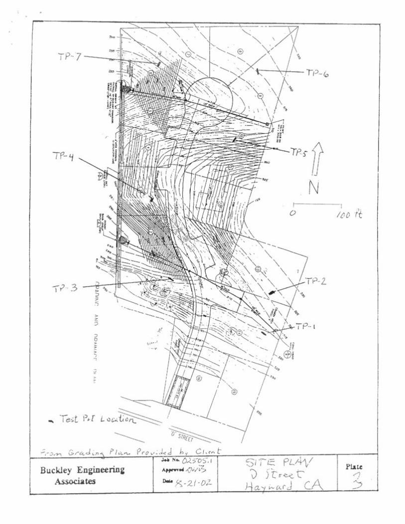
The site is approximately 3 00 feet above sea level in the Castro Valley-Hayward foothills, about 1.4 miles northeast of the active Hayward Fault (Geologic Map, Plate 2) . The site is far enough away not to be located in the Special Studies Zone associated with the Hayward Fault (CDMG, 1982). Parallel traces of the East and West Chabot Faults lie concealed under alluvium about ~ and 1-mile southwest of the site, respectively.
According to Dibblee (1980) the site is underlain by the Panoche Formation consisting of siltstone and sandstone with occasional shale and claystone interbeds. Northeast of the Chabot Faults, Dibblee shows that beds strike northwesterly and dip steeply to the northeast. We did not observe any rock outcrops on the site. However, bedrock was exposed at the bottom portions of all of the test pits.
The site lies in a seismically active region dominated by faults of the San Andreas Fault System. The trace of the active San Andreas Fault is located about 20 miles northeast of the site. The active Calaveras Fault lies about 7 miles northeast of the site. Major historic earthquakes produced by the San Andreas Fault System have produced strong to violent ground shaking at the site. The most recent of the strong earthquakes on the northern segment of the nearby Hayward Fault is thought to have occurred in 1868. This earthquake ruptured the ground surface along the main trace of the Hayward Fault southwest of the site.
In the aerial photographs, we did not observe any evidence of landsliding on the slopes at the site. In the 1939 photos the slopes appeared smooth, like they do today. The only difference in 1939 was that the site was covered with orchards.
In the test pits we encountered a variable thickness (from 1 to 7 feet) of generally low plasticity, silty clay underlain by sandstone bedrock (See the logs contained in Plates 4 6) . Plate 4 also contains general descriptions of the materials encountered. The sandstone was fine-grained, massive, blocky and fractured. In Test Pit TP-2 we measured bedding trending North 4 0 degrees west and dipping almost vertically. Joints or
any
Text Box
Addendum Attachment E-5/p.3

Wayne Ting & Associates Geologic Investigation Job # 02505.1
Page 3
perhaps bedding trending North 2 0 degrees west and dipping vertical ly were measured in Test Pit TP-7. Localized ground water seepage occurred at a depth of about 6 feet in Test Pit TP-1.
CONCLUSIONS
On the basis of our study, we conclude that there are no geologic hazards that would prohibit the proposed residential development. No faults have been mapped through the building sites, and no evidence of faulting through the building areas was found during this evaluation. Consequently, the risk of fault rupture affecting the project is low.
Geologists agree that the seismic shaking hazard is high in many areas in California, especially within about 30 miles of the San Andreas Fault System, which includes the San Andreas, Hayward and Calaveras Faults (State of California, 1996). Consequently, on the basis of the historic record, it is reasonable to assume that the site will be subject to violent ground shaking within the lifetime of the proposed project. Building damage due to shaking can be reduced provided the project is designed according to the seismic provisions of the 1997 Uniform Building Code and lessons learned from recent large earthquakes.
Because of the shallow depth to liquefaction is very low. The use retaining walls can mitigate possible on the steeper slopes to be developed.
bedrock, the risk of of engineered fills and seismic lateral spreading
On the basis of our site reconnaissance and the materials encountered in the test pits, we believe that the site is underlain by relatively stable bedrock. In our opinion, provided drainage and ground water seepage is controlled, either static or earthquake-induced landsliding at the site is of low probability. This hazard can be further mitigated through the use of grading, engineered retaining walls and prudent foundation design.
Adverse bedding (bedding parallel to slopes ) was not encountered during our investigation. Therefore, we do not expect adverse bedding conditions to be a factor during grading for this project.
Although backhoe refusal was encountered in a few of the test pits on the northern part of the site, we expect that the specified cuts can be achieved by heavy conventional excavating equipment.

Wayne Ting & Associates Geologic Inve stigation Job #0 2505.1
REFERENCES CITED
Pa ge 4
California Division of Mines and Geology, 1996, Probabilistic Seismic Hazard Assessment for the State of California, CDMG Open File Report 96-08.
State of California, Quadrangle.
1982, Special Studies Zones, Hayward
J. Michael Cleary and Associates, 1989, "Geotechnical Investigation, 2492 D Street, Alameda County, California.
Dibblee, T. W., 1950 "Preliminary Quadrangle, Alameda and Contra U.S.G.S. Open-File Report 80-540.
Geologic Map of Costa Counties,
the Hayward California:
United States Geologic Survey, Menlo Park, Aerial Photography: BUT-282-31, 32; 1:2 0 , 000 ; 7-26-39.
LI MITATIONS
This letter report has been prepared in accordance with generally accepted engineering geologic principles and practices and is in accordance with the standards of practice set by the geologic consultants in the area. This acknowledgment is in lieu of all warranties, either expressed or implied.
We trust that this report provides the necessary information. If you have any questions, please call.
Very truly yours,
B~.::~~IATES David W. Buckley Certified Engineering Geologist 111 0
Distribution: 3 to Wayne Ting & Associates
any
Text Box
Addendum Attachment E-5/p.5

Buckley Engineerin~ Associates
J.a No. o;;~.so·;;, l AW""• ,()vv'i5
o. ~-2..1-oL.
I
I -+ I I
1 N
' +
-+--1
I I +
I
PAlO.WA /. s.
-~ ---
~
'
\ \ \ \
--- '--,·,~-
'
Piau
\

':: di !j ~] ! ) .. - ~,., ... ,, .. "111
1 J ·, r:,1
1 ·~1 :.'L'~:::1~(~. '111
/·;:J,.('... : . ; ~;~:' . . fi l<duw•J ,. >! ' :: li :i I J. ' :i ··
· qiA s /f i' J{ o · v\-A,id d 1~1 )r~f1J(' i,: __ ! ! I •,, 'i! ' ;:- ·· ' 'I '
I !' '' j/' t )! ; if { .,. r1
I •i'--1 .. I'' : !( .. . . , .1'
I If I
" ii
Oacv Older 1\ i JL-{V~~rn...
K '? - ? 0.. h 0 L- h e F <)On tzi ~ () VL 1------1
aD6D {'t.
.- i)~ 'bbh:e , IYSD; 1-laywcuJ Q;....,.Jra" ~le. -. rro"h.
~No. D25'0c;', 1 (0iSOLO Gj t Buckley Engineerin~ AHI'".C i)..<./7'~ v '5 t. t"-{'~ ~tes 0.. >:; -:;2. l - tJ 2
I~ a h/Cil' j'
1 '· ;
IV] AI-' t- Pta~
(A 2
any
Text Box
Addendum Attachment E-5/p.7
TP··7
IP- ij
-::; 0 > 7
> ) 'l
> ,..
I'
Buckley Engineerin~ Associates
···)'
xw.,~-21-Dl-
IPr /]
N 0
~)i 'It~ PLA"\/ 0 f[t-tz t'
Pl.au

CD ® ®
) DC a. ) Lz_ed seefCL'j e.. ·
TP- \
IV 75W ....._
TP-2
NSD E
·i3l2dd~nj ~ 1V'to ltV> Veri~ c.:.a [ . \ t1 f). I >ea...., s )
Gra. y ·- bro~v~. silty Cia.y 8>yo~11.. s~lty t.lay, m(Jre cJa.ye:y /N:.tA. roc.k.. Pru5 rne_..i~
8odW;1. ' ·fro.<:iU.re..d) n,ac:;>:ve.. 1
soft io h.cud I .r~n e- jf'tt~he-d w~ath ere.d sand s;lOh 8-
Buckley Engineerin~ Associates
~No. 1.505.( Affr"e4;)wi:S
o. 'g-2.1 ~ D2_
IESI PIT LOGS D S'iree t
Hu..· · wa..rd cA ./
Plate
w
any
Text Box
Addendum Attachment E-5/p.9

Buckley Engineerin& Associates
TP-3
0
T e- '-1
N . 2 o E. ·· ·:::----.-.
JM No. 025'05: i AH""fell /Ji-v -z& o.. '6-2 i-o2
0 5 feet
-1 · s,)[sioh e.. c:.un !..CLt.'IS
c.~nc) sh.czJe. , b£/."t Jnc<~s ~ ve_
h.o bedcl~nj o bse!'ved
Pb.te
5

•
TP-5
IV 15 E
;V iO E
TP-'7 N
---
:fo~n ts: IV '20 w) Ve.rt;, <: "' ' or De. d "S :
Buckley Engineerini! Associates
J.e No. 0250 , 1 ~t4JJw3.
lWa 8·-21-02.
0 5 -ft
TES.T PfT LDuS D )[ reet
Ha wo..rdl C.A
Pbte (y
any
Text Box
Addendum Attachment E-5/p.11


.. ... -.--. t_:.~,
~-,,..,;,:·:r;~.= AOS/9zt2~6:9~2
~<JX 408/942-6952
~\:· ::~ _ fr?J -~1-~.l ::"'f ~7~ T j __ t::. g /}.~~~~_-:;,;=:: Iit~~~ &: riss-.:: .. c:.iate:~~ 4 4. :!, -::· C: ::.3 :.:; .. :..l t. !: ~ 1: lro.r:·~e :c E-.l \-··.:I
Proposed Suodivlsiort 2492' L ~;tx>~-::et:
:~ tti" - ~!.~) Dt-;J· ::_~~~I (_;SI _______________ ,_., ___
P:..'(:. g'-~ ::= r.. :~ 1 .. · -- ~ :~; :2 J'c?;::. # :J 2 _:. C 5 .. ::;.
.P:.:£.· :c ·e:;'~ft::.e ~:-t:.t2t.~ ~ ~:-:e 3-Y€ !) r ~:~- ·;.lJ.. t_'ii !'l:'} t , h.: -~ S-t7:<)l ·.::. ;; i c
..:_:.:;·:::~:er :r·ec·ort. ICJr· ::~ie :r·efe::.:·en.c:e:J_ }) .. r~-~(~-~ ~ -~_:t .. T·hi~~ -~~a-~ . .:.:-:;:t.1·1":..! -:::·t-~~~- .,.. -·- ~ c·7··~::!l t1t-~ tc- t t;.·:::: ~~:·vt :2rl·t.ia 1 .c l .s 'k .s J:-t:5 s c-c·:.a teci ~-\:.:. r-.. h geoloJi~ h~zar~s in t~is area 0f Ala~eda Cc~mty l n order to aid i~ the p l annlng and des~gn o~ t~L proposed residential pYCJe~t . Cleary Consultants provided a geotechnical i~vestigaticn ~or tha si.~.€ - i.r·. 2.989
J t.1. ~ sC:(:;-pe (J{ s~r,.;·ic~es t1ncie~r-::a ker~ t.() ~3r .. ~Cl \.Ye a.t. t. l~ e fi::--1c~ir~g·s
~cnc:~s1ons i~ t~~s report i~c!uced:
• Re~lew of gao~~gic maps and reporcs sovering ~he sire area.
• Site reconnaissan ce of t~e site and dUrrou~ding area
r::_;f ex c a ·:Ta_ ·c ~~-j_
~ Analysis a nd preparation of this =eport.
any
Text Box
Addendum Attachment E-6/p.1

c~~~e ~i~~ ~ As~~~~a~~s 2~~:~~ic =~qe&ti?~~~~n ·:,~:b FC12 s-~ .' s ~ 1
s:rncc;t!-:·.1 \t
.. '
-·~ -~ . .: C: t ~.! J.. -·-- -~-. :5 . -
~ctive Hayward Fa~i~
charact~r~ze the sl~e. co~luvia~-filled.
c. r:. ·.) :_~ := !Hl.l. e~
J?late ·; ' -J
, • .,. T' . )' - ~~ th . ..g
site is .-;:: - . . _,..._ j..;::l.!,._
~D~ugh awdy ~ot to ne locacea ln che SPec2al Studies zone ~ ::. s~J -.::i. -s.r:,(~·=.i ··J i__.c:r··: l he .:.ld ~--~-c.: l :~ Fall.::. t. ~ C:Jf<:; J 19 8 Z) ~ -~. a .. r a l le:l. :.. :;c·ace .s ' .L "'Cii·C ~a_:a:. .:3.:"'_.~ 1\.::·st C~-~-~-~):._2. ·~- ?·o_ :_:~_t.·s .l ~~E:-- COfiC:e.a~~ec1 u:-~cie.'C 8). ____ :_r:ll.:_·:rrt
~-:7.tl.l ··c: .S_y.3t.err: ha~.rt pJ:-r:;;-:!tl-cecL st :co.r::~-, tc~- \t:L~Jle.r~t ·;;rt:it~r!d s.t1aki:0.'3' at T. ~r.e Sit .. e .. -ffi1-E:. :n::)'37:. 1:.~--e.. C:~~)_t.)~ c::;f ·en.:~ ':> tron~;~ -CCt!:t_t~ -~tla.ke.S ·::~-l t!l~
.n·::~ct.l-1erri se:;iT(1e.n:t G·f :~:r~~e t:ea.cL_y ha:y~·'fi-:1.:~~~ f'autt. i.s t!1c.'ug·ht. ro !1a.\r{:;
occurred in 186b.
?he only d~ffere~ce
I-~1 "!_:Y.te 1:· es:.: ~).i.t. ~3 'i.!¥".8 C:~tC()l.IT! t.£~ __ --r.ed 2 ·., ... a .C ~i. a.·})·.J..e ::-f~~i ,..~~.k.Cl€ 5 ~· ( f y·c:-rn 1 t ·:: '/ -_p..,.:!.~ .• · ,.-_.·.1.~ ·~.-:='/;~l~.r .. ,::::.L. : ·;r _1."~~. ·· ~·· ~~-;_.~c...-:--._.;_.("_~ r. :' .. "~.-- · -,, ~ -·, . --- ~ 3 - ·~ _, .. ~ ~ ..... ..:i - _. r., ;- .. _ ,..._. - - ..... ... ..: - 8 ~L ..:.. ··: }''. C.::_~~.}-' ~-r ... (t£.=.;:( J...d .. tr.;. ;:~~{
san\:lstor!e J:;ed:t::::;.,::~ ;:see t:-!~ lc~l;s ~:::c.r~t~.Ln. s'j in PlA.te.c:: 4 ,,._ .

I-.:~":; :.cl:ar:.~ s. t:.-e :id-i :rlr;; \t-er.~~-=.i ::::all':! ·v.;e !:·e
-~-: ~-Ft ~~( y·i-<J- c::a .. I~: '.
_,;._,~, :··-~.: :':>['("1 ... \ 'A(] t ·=·
t. .L C>: T I d ·: .. -~·~- :::~
rnEC:S'JJ:."'8d.
-:- r~ -, }.E.;-._.
. ~ 1r' !- ···;._.
~..,..-~ ......... ""';-, .... ~ "::;1 ..:... ... .,J ~ .... .! J. .... ...
that ~~ere ar6 no
a.x E:~ s·-
3u ~i~es of the San
-~ - ---~-···. --···, .t"" l...o.C..-L..UC-!."::_JO
;;::'1:·- o j e c. 1: i. ~ 1 C• C; '7 TT ..-•. ; ..__~:: ,-., ...-. .... . ............. _ .......... ............ ~ =-' -, ..: ; --~ ' .... ··-~
.:._,__, • ..1-_ ....... __ ;..l'-_j
Code ~nd Lessens learned !r~m re~e~t ~~zge earthqaakes.
o::: li.g1iefo.ct.:L()::':: fil ~- -~--.:.:··=- ·-;~i:::~ _j_-:1.1. ~'!-·;1 \'•.l _ ~j_ l~~-: ·_·;a.~-~ :r:n:;_ -r: l g·-.a -~_:. :::; i:"){)·~· S_"l.iJJ..G S :2 2.. -Silt.l ~:: la·t,S:r 2.1. e;.f:::t f;.~.c1 i.~-9 02 the steeper sloces to be developed_
foundation design.
test ~---. ~ 1·· ·=r :...-· .......... ....... .:-.'\...,- ~ ..
L-r.~a;_ t.hs
any
Text Box
Addendum Attachment E-6/p.5

I~- •}~:.-~st5~:~;~.·:i<J::~
~ .: ·-::::·:t-. Tr ·J LD:.::S .. 1
l Q (,.'; .r-: --- ....,. ~
SE.: ~ ;_,;Yfti..~:.:. H.:::.z.c~ rc~ J~s ~E:- .;'3 ::;~n·~T".~t. :.~:.:':.:c ~r: 1::;.~ 3.t .. ~t. :.::.· -:_) £ =:al:.. f ;~z:.r:i.a . p F1ie Report 96-CB.
rlaywarn
Cl.ea.r:'l 2nd Ass ·::·c:~at .:::: s , 1 '18 9 t "Ge<:>t: :;,:.c':--.!;ical .2 4 9 2 D 3 t. r -::::e t'" ~-;l .~!necia ;_~-Ct,::.n t y J c.a 1. t f o 1:-n. t a ~
C~.(t'Llll. "t l e S ..
2:2; - · ..... ('. , .... . . ; y
-· ;t~ 1.,}) ·...!~,) '"'-' ;·
~~ -! ~r·ro~li T ,~~-r = c;~I s • - ------••"o•O<o•M•-·- • •••••~~~.---
.:.. !'l.l..:3. l.·?t. t.-2. I.:
, ... . , -.-~ ... " t" ~ ,,"":,Q J.;:-' ·-· ....... . _, ·- ..... ·--~ ·~ · set.
,':1 r-~ ~-y·\ (";, r .) ·; ~ ,...1 ,-.. ·ry~ •.. o·~ ...... j-· ·- ~- .... - -·--- "-J•··-·" v
yOU nave dn~ quest~?ns.
3r.JC:?~! ... EY. El:IGIN· E~~~~It·.IC: .-~\
./"·-~1 •t
_ .... '\_./~t:f' ... _/t. t.:v-

--~~ .. ~-~~-0:--:-~ ..
--·~
~;,'';'~~~'rjRt . '\:~ /> ;J.fjJ / ·- ·' ..
. ~} .. __ ~_ -· •!,•
~t~?'
/~'~;;;:·
:';~~1 - :~:-.-.:·~ ·r _:-- '*..;:;---
·'" !:~l .·' ,.• ' '.'; _.;;.~·.r-
~-/ ~~ .... , ,.,..-_,
,-t~.,:. .-;f .
...... -·--·1
~- ~ ~--'\. r
-- • ..t .. -.
·- .. "\
.-.. -, (_li
any
Text Box
Addendum Attachment E-6/p.7
\
,. /
·~-· r<~ ·~:.·
:_~/ •. J ,: ~.::. ...
.-. . -.,..__ .
'.''.·
... • ·.
· .... r \ ~.)/
·· .··.
,.,..------· --.-..~--....._-'fi~...,~r·~.M'":·-~· ~.""N:"'_¥,-!~:~~.;:'='", ~;£.; ~~- ~M>r---···~, ... ,..~~ ~- ~~J-~., ....... ~ ...... , ... ................. ~,-- .......... _. .......... r ... ··"""""""'---~--4 • --· :._:! ~- ·-"' ·~ . ·· .: __
--·--·-.:

1)'1
I:.J
l.d ·,!) ·~ n. () ':t ~£:
!'-·'i o~: LU
~!)
I l
c; f~i t_
"!
~· i }
·•!
•.J , .. 1 1
'.1
;:~~
t:~ U"": {•,)
~r:
·:r tU
()_l I';)
•,")
'-·' . ·' ',
-
1.',' \"
,•
r---------------
1 I l
1.,1 ") •'\
<'
..,_
r .:1
I I I , .. "~
1 I tl :-
l 1"1..
~ \
k_ ..... ll ..
~--I -" .. . ... ;
l -
/ .
\ ,', , \
. :·~.J:.
1\' ! . ·
, ,,. . ,,_, .. j
I .-·
, ,~
. ~
' . ,·
' \ : ·<'. '·. }, '•
! •
' \./ >
'_/,;/ r
\; ··l·' "-'~: J
:· :
_,
.-1 ,r \
1 ' ~ ' I ' ~-~ \
' ~l
""\
J ~
_... l
.,_ ,
·-r L'.~' ,li\w
,·Prrf -
I.
,_ .r
... !;· ..
.. :..... ,
\
\ #
' _
I j·'t\\
11 . 1JJ~.\i't1\l\L"f.l\} i . 1 ·I
. · ,f'
J f
/ 1
11 I
'1 '
j1 ,i\1.1(1
11 '
~-' '
•l' I
I .•
I ·~.
't\•j
l i'lj
I IJ~r~
l,~f
. /
'• '
, "r,
>
,• ~
I l
' ~
II \
I I
l •
I ~
' '
' -.·
I ·/1-
J .tl,/it'r·~lA:IL'.'\'-''', ·•. -
"--'!,
. .
. t
/--,, .. __ . ::·
1
1 ,_ "'
, ,, .. ,
I. ~-~,J~~~./I'tuHI'.'<I,_.\\ '-
·-.
. .• ·...
, ..
i / .·
r. / .-.-·,.
l .
/)''i' I
,1,11~\.-u.:l~l r~IJT·\ ... \'.~·' t' .;
:··],.. ·-..
{mt('· ~,.,..:: .... ,_ '.·
J '.f
/ i
;'.
';~~:
·"
l ~ i
. : .,/· -----,tDl~·,i .. ~~;jf ~!il.li\ri(~l·\\\·~\-.:\'; 't;·:~--~>. ~ :~· .. ;_ :-... k
:-.·!¥(?·. ·;·?-·f,~, ·~··i~,);··. .f'.·
.,. t
i /~
,,· '.
1 ~·';
1!1 ~,
n~~.-
~ _, ., •·'·::·_ ..
-..:..-...-~ ..... ··~~ ·.· .. s .. 1
·' ,\;tl·"~·') :fl
~, ·/
I I
• f,
.: I I 1;\ 'I; \·l
'1Jii1
l',·:· t. ~'-·_
.,,_ ,, ~-., '-;'~:.:;~;'~~--.
'.I I
P,''
I·, i
,I ••
• .'·
. I
! "II I ' ~
l •
,, ' I
l '
' -
1. 1~ ·.J.
• •
i.~..
v"' f ~
~
. ,~ •
" I
.'
,. ~
I '
t .
·,I .t
.i. ~ .. y'
"lr
~~~ ·~·· t..r;',.,\?\.1
1, ~
·l . ; __ ;:,-.: .'
~ _-
1~;;~ .. (·· 1 ...
_ ... \
·/ ;·: ~·
r --~~
,.-,
10' ~,•.'
I'
\j
',•,'-t ''
• •
•'~"~J
~«
'~
I\" ...
I _
): !•
.. )i
l'
'•ft
'• ,_
_ ,~....
..,(
..... ·•. ,,.'-
t .
·' '-1
')
i
'
1.
·\.
i)f\:r:·
~l!l.\ 1 i-~~
~·~·J·;,..,\·,
t :.;-..
_·, ..
~>..".'~--.("··
· ··
.-t~~~4 /,/J
-·.v-.-:.i,r
' / ~I;
" '
; . j
•
·•'
! ' I t_ /
I i r
t; i
i,l .. )
! I.' ..
11
'·/
,[
•.,1 11 1,·\···
1\ll,·.,tl.
, ·~-
/'· \-'·
.·-·,·. ·r----;
_.,,1
11
I , 1 -·
· · '~ .. -.~/>/~---~/.t .. ;:t:l:;~\\'-;·~~-.:··,\. ·:_;-':. · ·----: ~~-~~~~:.:·· ·.-:<J_, ·':· ._.-:· .:/f"!·:·~~::,:;K::~;:;--~/ -) 1 .. I
\ . '
•' -
' ( r _(~ .. \,,t·\l•
t '
' ,\ t
-.
-----
-,,.
.-' ' ~--;:i"J.·t·r l ' •!'li••"f' /.-1
' ,_ :i l
~)' ·~1,_:-,='~:o. I
{ .• ,~ ... ,, :·~,,-ff
;/, J
~.-... :'·l·jt'~??.r..ll''· .. ~···t!~ ... 't
,t
11\ :i"·.
~ .
•jih
'-
·.
' .• ,-•<ilif:"~"'i~~/}':,..':
1 .~·~/1<·,·'·;'
1 .... ,
..
-•
.:-,_::i,,-
.-!AJ\,f.
',,. 1~11
• 1---"<~
;1
',:
• -
·.
.. ·-.
·_,r ·:-•·_.,"Jj-
-~',-.;{
o->"'1, 1•-v;
• -1-
...... i
•.;.!'~~·~··'
1•
1,
1...,. \
~ •
;.f ..... ---:.'r'~·,...r'"
r'J.~-
,I
~-'·:, ..
f,
I ~-·~:--.
.. :'' .· --\' , . "' .. , , . ·~· I
,, -----·•'
,,_(,k ~-.-<
''~ s ·.f·r' r~·
1.1. '
. .
~ _.
~"'\~ ;:-,.•',
~._ .'~,.
• l::t--1::,
l 't
•'
1\
•, ',
' \-.~
• ··•
.-
.... ~~~·!:;;.-,;~,.,
--'_.:,•::::. I"_,J
: I
I 'f.
I ,II,
• J
• f'l
• r.
-e<:.-,,
-:"'t'··
ql.,):.;.--:' .. >1 ~1
1 '\
1
...... ; ",;o-,.-.,~, .,, 1~•-:JI:.n
-<1;),,..,, ,•,
:
1 ; ... ·<'~.'~t"~r.J~~~--::~~:~l~,~~\r.: \: \._ .·· .-. ·. __ j-~ ··--Y~:-_v~: -~ :~ -'ff~i;~fl~llil!/~:~-t-~·-.. (·;_.;:-'.l
,I
I I ' : /
.-i · 1-.?l .;_; .J!!J\:.~4-· ~;\::., ·", _, ~· 'i _,
: "[•->·
.· r
•">7 i ;;: 1'•7{"~~~ ;-01 -r
i I, . .-/1·
·'r/' i I
l \! '
1 •
,• I ,''
'...
·:.:r.-l, '-1:.\:.)\·' ' 1'\ \·. '•
-1:
:. -
'{\
. ·'V
,-:~-·-·;-;Jp 17,-;;.I 'I I
. ·//' \
-, i
i//r _,-/· /·J~::,~~--:~~:.~r~.r:~:~~:: .. ~~~j> __ =-~-·· . ··:::,~:¥.~~~:~~ .n.~r.:~.;;;! 0;~:1Ji~.:/l~n{_·~\-:, / .. / l L ·L .
, -~ti''·"'•b;·. :-.• I~B~!A;,:"' ---~·v ._. ,~---··•·~-'9 f·· ;, -_,., --''·-~·-.;;;~ ~~y-;;,-:; •.•.•• 'f'·'4t;,_.;-.:.. i--
· l
1 ·;, · r· ~-· ·-lzr;.__:~:~g1'~:.:--· · .. ··;· ~~-::.
~i ... ,:· ,..
-t~· :·.".
·'/
) ./-~;~~·.~~~/ 1 /
I I
r,-:.·.. ~:.:~·:--,~..
". ,;
·+"·e~·It ,,.,,,
i /
..•.. " ..
. .. ' \ ..
. . '
.1 /
1 ......
.· i,'"t·;
ll ,.; ·
~ ' .
I \)
1 I
--l.
1 I
, ·, r:S >.
·1.
l
.... , .... ~---' .. ~.--
.-· .. ...,.
·~..... -
!! •
~:·H~'t,..,s. ...... _.:~t
~/
... 4
!..1
. ,. ' If
/I ,
,.f f i ,-
1
1..' r
1 ' :t2L 'I
~}
-i .{
I'
I /
-·~ .':1
';
}·
(.
1·11
I I 1
\
'' .. '
' ~
'L'
" -j
v :·, .' l
I,'\ <1\ ~ I i ,+
-·I :•I .. } \ I.
'l I
'· ~I
( ~ ...
' '
' I
.'.l ... , I I
}\
! •
. .-1 \
~ ·.-·
~: 1!
..
I l 1 I • I
~1 3
'tl l
~ ~~ l ~
•.. c 1
.. t ~~
~~ ,.~~
'
~:,
' ,;,
·~ :111
.-~: '
t~
':.1
;l:l i
.J
any
Text Box
Addendum Attachment E-6/p.9

-. ·-
,..,.., .. -.. ,,
~:~-/
_ ..
. .:--'·
I
L-i
;_ / .. 2. G.-.3 ----~ . -~ ,,_:,. ~.,;; p ( - -=· c... .-_.
:·.:;_.~_. / i \. .. ; - !
, ..
o:· - ' •r::.. _j
_ ... __ _.·1 __ ~
--fj •.,;;I
f .-,.: .. tJ: s
·f y-~ fACi r:;-~r
·"' -~-~--c::) !.r u ~--!., • .. ·-l ... ;~·r{.J.. r~ ~~- W,.- r C-(.J ~1'1"'·~-';._ r_.f) C..- c:J
..! . . ' ·..,,·vw-~ ~ f.)"t - e~~r-c .. d
J•i#.r.t
I I -"1 /-~- 0_ j: iA-" r..t. t" ci _,
-~~------~--~--------~------------~~~~-~~~~~~~-~

... _l',._rj.:::. •_: ::':
.;anv=ntTr>-
1 ·=-t= •
\~
\ \ ..... ~__..-,,
---0-- ·-·
-----
~r:;- ;··;. r 1 J , .. ·"··-·· ....... .,,
- - .1C.
Y\ o {;.:_, -e J .d -~ .. r. 11.:: ~) }; ~=: :;,=:,/' ~ ,r·e. <-J .J
I ; <
!
any
Text Box
Addendum Attachment E-6/p.11

..
! I i j '
- . ..
-::. --' ) ---
----
.~ LJ t:: ~--·----· :.:::::.::-~ .
J
! .:"' , .•. ,,,:;2 ... """'" : •.·-·~· - 1 i --~~-~ A ~ :s·---:;,~-t~- c:z_
-L:.. ...:~ ..:o··, ....... c •••• , : ..... ==:;;.----~···~· ~~=----=·-..... ~;;.;..:;.:...--------..:....·;;:,;,::;::.-L~-----
..,_
---, ;
(
j I
r .J---____________ __
v 5 -,. ~

GEOTECHNICAL INVESTIGATION
TRACT NO. 5965
2492 D STREET
ALAMEDA COUNTY, CALIFORNIA
CLEARY CONSULTANTS, INC. Geotechnical Engineers and Geologists
any
Text Box
Addendum Attachment E-7/p.1


CLEARY CONSULTANTS, INC» Geotechnical Engineers and Geologists
Mr. Lubomir Peichev 106 West 43rd A venue San Mateo, California 94403
RE: GEOTECHNICAL INVESTIGATION TRACT NO. 5965 2492 D STREET ALAMEDA COUNTY, CALIFORNIA
Dear Mr. Peichev:
July 7, 1989 Project No. 219.1A Ser. 3930
In accordance with your request, we have performed a geotechnical investigation for the proposed Tract 5965 at 2492 D Street in Alameda County, California. The accompanying report presents the results of our field investigation, laboratory testing, and engineering analyses. The site and subsurface conditions are discussed and recommendations for the soil and foundation engineering aspects of the project are presented. This report is contingent upon our review of the grading and foundation plans for the project and observation/testing of the earthwork and foundation installation phases of the project.
We refer you to the text of the report for detailed findings and recommendations. If you have any questions concerning our findings, please call.
Yours very truly,
CLEARY CONSULTANTS, INC.
~ere J~~-v-Rick Swanson
~il Engineer ~88:1_
\j~ii(AJLA-~u~ J. Michael Cleary 0 Engineering Geologist 35 2 Geotechnical Engineer 222
RS/JMC:ms Copies: Addressee (2)
Marvin E. Smitherman, Jr., Consulting Engineer (2) Arkady Faktorovich (1) Gene St. Onge (1)
900 N. SAN ANTONIO ROAD, LOS ALTOS, CALIFORNIA 94022 (415) 948-0574
any
Text Box
Addendum Attachment E-7/p.3

TABLE OF CONTENTS
Letter of Transmittal
INTRODUC'f I ON'. • • • • • • • • • • • • • • • • • • • • • • • • • • • • • • • • • • • • • ••••
smPE .......................................... "" ....... .
METHOD OF INVESTIGATIOO ..•.....•....•.........•••..•..
GEOLOOY AN1J SE I SMI CITY . .................•.......•.....
SITE A. B. c.
CONDITIONS. Surface ... Subsurface. Groundwater.
CONCLUSIONS AND RE~ATIONS .. A.
B. c. D. E.
Earthwork ... 1. 2. 3 • 4. 5·. 6. 7. 8 •
Site Preparation. of Surface Soils.
Clearing and Recompaction Placement of Fill on Slopes .. Slope Gradients ...••..••....... F i 11 P 1 acemen t and Compaction. Trench Backfill .. Drainage ..•..... Construction Observation ..
Foundations .... Slabs-on-Grade. Retaining Walls. Flexible Pavement.
~ . . . .
PLAN REVIEW AND CONSTRUCTION OBSERVATION ............. .
BIBLIOORAPHY
SITE VICINITY MAP ... SITE PLAN .........•.
FILL SECTION. ENGINEERED KEY TO BORING LOGS ....•.
DRAWINGS
SUMMARY OF FIELD SAMPLING PROCEDURES. LABORATORY TESTING PROCEDURES. LOGS OF BORINGS 1-12 .. PLASTICITY CHART .... R-VALUE DETERMINATION ..
CLEARY CONSULTANTS, INC.
Page No.
1
2
3
4
5 5 5 6
6 7 7 7 8 9 9 9
10 10 11 12 13 14
14
Drawing No.
1 2 3 4 5 6
7-18 19 20

1 ,. \
INTRODUCTION
This report presents the results of our geotechnical investigation for the proposed
Tract 5965 at 2492 D Street in Alameda County, California. The property is lo
cated on the north side of D Street about 300 feet west of Stratton Court as
shown on Drawing 1 - Site Vicinity Map. The purpose of this investigation was to
determine the prevailing soil and bedrock conditions within the areas to be
developed and provide soil and foundation engineering recommendations for the
project design:
As shown on the Preliminary Grading and Tentative Map by Marvin Smitherman, the
project will consist of twelve new single family lots at the 2.8 acre parcel. The
project will also include construction of a new cul-de-sac street as shown on Draw
ing 2 - Site Plan.
Construction will consist of single family homes built close to existing grades. The
homes will be one and two story, split level structures. It is anticipated that the
homes will have raised wood floors in living areas and concrete slab-on-grade
garage floors. Cuts and fills up to eight feet may be required for the street.
Grading details for the building pads are not available at this time. Trench ex-
. cavations 10 to 12 feet deep may be required for the planned gravity sewer.
We previously performed a geotechnical investigation of the site to provide soil and
foundation engineering recommendations for a condominium project that was not
built; the results of this study were presented in our report dated October 31,
1979. In addition to this report, we prepared a November 23, 1988, geotechnical
feasibility update letter which concluded the presently proposed tract development
is feasible from a geotechnical standpoint.
1
CLEARY CONSULTANTS, INC.
any
Text Box
Addendum Attachment E-7/p.5
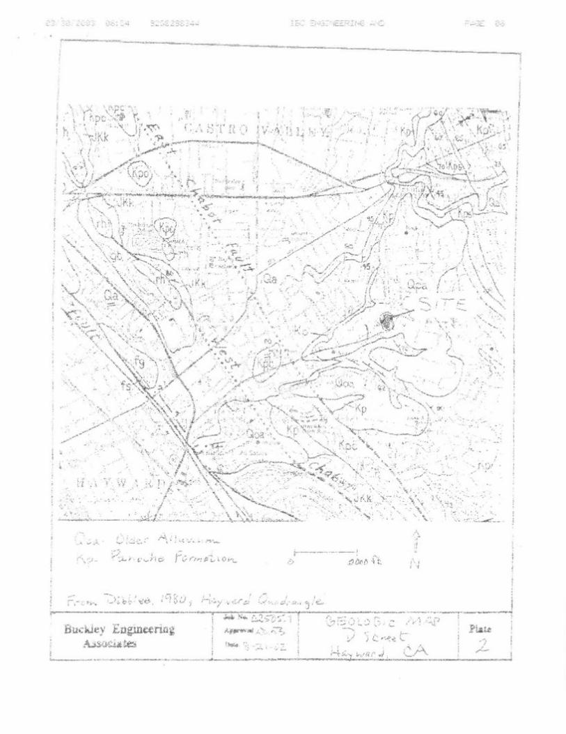
. SCOPE
A~ presented in our proposal dated June 2:, 1989, the scope of services for this in
vestigation included:
1. A site reconnaissance and review of available geologic information for this
area.
2. Subsurface exploration consisting of six borings drilled under the guidance
of our engineering geologist.
3. Laboratory testing of samples obtained from the borings.
4. Soil and foundation engineering analyses using the field and laboratory data
and preparation of a geotechnical investigation report. The report was to
present findings and recommendations for:
a) Suitability of the proposed building sites from a geotechnical
standpoint.
b) Site preparation and grading.
c) Building foundation type, minimum depth, and allowable skin friction
values.
d) Treatment of expansive soils.
e) Surface and subsurface drainage.
f) Earth pressure criteria for retaining wall design.
g) Excavation conditions and utility trench backfilling.
2
CLEARY CONSULTANTS, INC.

h) Flexible pavement sections for roadways and driveways.
i) Any other unusual design or construction conditions encountered during
this study.
This report has been prepared for the specific use of Mr. Lubomir Peichev and his
consultants in accordance with generally accepted soil and foundation engineering
principles and practices. No other warra.11ty, either expressed or implied, is made.
In the event that any substantial changes in the nature, design, or location of the
improvements are planned, the conclusions and recommendations of this report shall
not be considered valid unless such changes are reviewed and the conclusions of
this report modified or verified in writing.
METHOD OF INV:ESTIGA TION
A site reconnaissance was performed by our engineering geologist on June 20, 1989.
The subsurface exploration was also performed on June 20, 1989, using track
mounted, continuous flight auger drilling equipment. A total of six borings were
drilled to a maximum depth of 16.5 feet at the locations shown on Drawing 2. A
key describing the soil classification system and soil consistency terms used in this
report is presented on Drawing 4 and the soil sampling procedures are described in
Drawing 5. Logs of the borings are presented on Drawings 13 through 18. (Logs
of the previous borings drilled for our 1979 study are included in this report as
Drawings 7 through 12).
The borings were located in the field by pacing and interpolation of the features
shown on the drawings provided us. These locations should be considered accurate
only to the degree implied by the method used.
Samples of the soil materials from the borings were returned to our laboratory for
classification and testing. The results of moisture content, dry density, percent
finer than No. 200 sieve, unconfined compression, free swell, R-Value and plasticity
3
CLEARY CONSULTANTS, INC.
any
Text Box
Addendum Attachment E-7/p.7

index tests are shown on the boring logs. Drawing 19 presents additional informa
tion on the plasticity tests and Drawing 20 presents the results of an R-Value test.
The laboratory test procedures followed during this investigation are summarized on
Drawing 6.
A bibliography of references consulted during this investigation is included at the
end of the text.
GEOLOGY AND SElSMICITY
The site is underlain by highly weathered siltstone and sandstone of the Panache
Formation (Dibblee, 1980) with occasional shale and claystone interbeds. Bedrock is
exposed in cuts for the existing dwelling and access road at the site.
No active or inactive faults are known to pass through the site. The property,
however, is located approximately 1 1/2 miles northeast of the Hayward fault, 20
miles northeast of the San Andreas fault and 7 miles southwest of the Calaveras
fault, all of which are historically active. Therefore, as with the rest of the San
Francisco Bay Area, the property is in a region of high seismic activity.
Although research on earthquake prediction has greatly increased in recent years,
seismologists have not yet reached the point where they can accurately predict
when and where an earthquake will occur. Nevertheless, on the basis of current
technology, it is reasonable to assume that the proposed residences will be sub
jected to at least one moderate to severe earthquake during their design life.
During such an earthquake, the danger from fault offset through the site is remote,
but strong shaking is likely to occur.
4
CLEARY CONSULTANTS, INC.

SITE CONDITIONS
A; Surface
The property consists of a broad central ridge flanked by a sharply incised winter
drainage to the south and a shallow minor swale to the north. The central ridge
slopes westward at 7 to 14 percent and has 20 to 30 percent sideslopes on the
north and 24 to 50 percent sideslopes on the south. (The slopes steepen near the
bottom of the creek). Elevations vary from about 329 feet at the east central
boundary to 282 feet in the northwest corner in the swale.
At the time of our investigation, there was a. home near the center of the parcel
and several small sheds in the north swale. Access to the property was provided
by an asphalt paved driveway which is ·underlain ·by fill where it crosses the
southern drainage. Vegetation consisted of a few trees in the northern swale and
several large trees, shrubs, brushy debris, and weeds are in the southern portion of
the parcel.
B. Subsurface
The borings encountered 0.5 to 4.5 feet of natural soil overlying bedrock. The
natural soil consisted of very stiff to hard silty clay, sandy clay, and sandy silt and
loose to medium dense silty sand and clayey sand. The bedrock consisted of highly
weathered and fractured sandstone and siltstone of the Panache Formation that ex
tended to the maximum depth explored at the site (20.5 feet in Boring 5). Minor
sandy claystone bedrock was encountered in Boring 10 from 4.0 to 6.0 feet deep.
The bedrock became progressively stronger and more resistant with depth {drilling
refusal was encountered in Borings 6, 9, 11, and 12 at depths of 10.5 to 15 feet in
the hard sandstone bedrock).
5
CLEARY CONSULTANTS, INC.
any
Text Box
Addendum Attachment E-7/p.9

The. soil and bedrock materials have variable plasticity characteristics and have low
to high expansion potentials (plasticity index = 8 to 3 0). The results of six Atter
berg Limits tests are shown on the boring logs and on Drawing 19.
The attached boring logs and related information depict subsurface conditions only
at the specific locations shown on Drawing 2 and on the particular dates designated
on the logs. Soil and rock conditions at other locations may differ from conditions
occurring at these boring locations. Also, the passage of time may result in a
change of conditions at these boring locations due to environmental changes. .
C. Groundwater
No free groundwater was encountered in the borings at the time of drilling. It
should be noted, however, that fluctuations in the groundwater level may occur be
cause of variations in rainfall, temperature, runoff, irrigation and other factors not
evident at the time our measurements were made and reported herein.
CONCLUSIONS AND RECOMMENDATIONS
From a soil and foundation engineering standpoint, it is our opinion that the site is
suitable for the proposed tract development provided the recommendations contained
in this report are incorporated into the design and construction of the project. The
gently to moderately inclined, rolling site is underlain by expansive soils to variable
depths, consequently, we recommend that all residences and retaining walls be sup
ported on well reinforced drilled pier and grade beam foundation systems. The
drilled piers should be designed to obtain skin friction support in the bedrock
materials that underlie the site. All concrete slabs should be underlain by a layer
of non-expansive fill to minimize potential soil heave and shrinkage movements.
It is anticipated that conventional grading equipment can be used to grade the
planned street and building pads. However, difficult drilling of the drilled pier
6
CLEARY CONSULTANTS, INC.

holes may be encountered locally and we recommend that heavy duty drilling equip
ment in good working condition be used for the pier drilling. In addition, heavy
duty trenching equipment and jackhammers may be required to excavate deep
utility trenches in the planned street, such as the planned sewer trench.
(Excavation contractors should review the boring logs and observe the bedrock out
crops at the site to evaluate the excavation characteristics of the bedrock).
Detailed recommendations for use in design and construction of the project are
presented in the remainder of this report. These recommendations are contingent
on our review of the earthwork and foundation plans for the project and our obser
vation of the earthwork and foundation installation phases of construction.
A. Earthwork
L Clearing and Site Preparation
Initially the site should be cleared of the residence, sheds, designated trees,
brushy debris, and any other debris or underground obstructions encountered at
this time. Any holes resulting from the removal of underground obstructions
that extend below the planned finished grade should be cleared and backfilled
with suitable material compacted to the requirements given .·below for en
gineered fill.
2. Recompaction of Surface Soils
After the site has been cleared and any underground obstructions removed and
backfilled, the surface soils in areaS to be filled should be recompacted. The
recompaction should consist of ripping the upper eight inches, moisture con
ditioning the soils to approximately two percent above optimum and compacting
them to at least 90 percent relative compaction as determined by ASTM Test
7
ClEARY CONSULTANTS, INC.
any
Text Box
Addendum Attachment E-7/p.11

l l i
I Designation D1557-78(C). Compaction should be performed using heavy compac
tion equipment such as a sheepsfoot roller or self-propelled compactor.
3. Placement of Fill on Slopes
Any fill placed for the road or buildings on slopes steeper than 6:1 (horizontal
to vertical) should be keyed into firm undisturbed materials with a minimum
key depth of three feet. As the fill is brought up, it should be benched into
firm soil or rock with a series of two foot wide benches. The actual extent of
keying and benching should be determined in the field by the soil engineer.
A subdrain should be placed at the back of the keyway in the planned fills
across the swales as shown on Drawing 2. Details of the recommended keyway,
subdrain, and bench installations are shown on Drawing 3 - Engineered Fill Sec
tion.
The outboard portion of the existing roadfill across the southern swale should
be reworked in conjunction with the keying and benching operations for the new
road. The inboard portion of the existing· fill, although expected to be suitable
in its present condition for support of the new road, should be tested during
construction. The existing fill should have a minimum compaction of at least
90 percent relative compaction as determined by ASTM Test Designation
D1557-78(C). If the fill does not meet 90 percent relative compaction, then
the fill should be recompacted to at least 90 percent. The soil should be
moisture-conditioned to about two percent above optimum and compacted in ac
cordance with the recommendations presented below under Item AS, "Fill Place
ment and Compactionn.
8
CLEARY CONSULTANTS, INC •.
Slope Gradients
Permanent cut and fill slopes should be no steeper than 2:1 (horizontal to
vertical). Cut and fill slopes should be planted to minimize erosion. Surface
runoff should be diverted away from the top of slopes and carried to a suitable
drainage collection system.
5. Fill Placement and Compaction
On-site soils having an organic content of less than three percent by volume
can be used as fill. Fill material should not, however, contain rocks or lumps
greater than six inches in greatest dimension with not more than 15 percent
larger than 2.5 inches. All imported fill required at the site should be
predominantly granular with a plasticity index of 12 or less.
Engineered fills should be compacted to at least 90 percent relative compaction
as determined by ASTM Test Designation D1557-78(C). Fill material should be
spread and compacted in lifts not exceeding eight inches in uncompacted thick
ness. The moisture content of the soils utilized as fill should be adjusted to
about two percent above their optimum moisture content.
Pavement subgrade and aggregate baserock in street and parking areas should
be compacted to at least 95 percent relative compaction.
6. Trench Back!lll
Pipeline trenches should be backfilled with engineered fill placed in lifts not
exceeding eight inches in uncompacted thickness, except thicker lifts may be
used with the approval of the soil engineer provided satisfactory compaction is
achieved. If on-site soil is used, the material should be compacted to at least
85 percent relative compaction by mechanical means only. Imported sand can
9
CLEARY CONSULTANTS, iNC.
any
Text Box
Addendum Attachment E-7/p.13

also be used for backfilling trenches provided it is compacted to at least 90
percent relative compaction. In pavement areas, the upper three feet of trench
backfill should be compacted to at least 90 percent relative compaction for
on-site soils, and 95 percent where imported sand backfill is used. In addition,
the upper six inches of all trench backfill in pavement areas should be com
pacted to at least 95 percent relative compaction.
Crushed rock (3/4 inch maximum) can be used as trench backfill, particularly in
the deeper portions of trenches, and as pipe bedding materials •
. 7a Drainage
Positive surface gradients of at least two percent should be maintained away
from the structures so that water does not collect on slopes or in the vicinity
of the building foundations. Water from roof downspouts, pavements, and slabs
should be directed into drains and/or closed pipes and carried to suitable
drainage facilities.
8. Construction Observation
The grading operations should be monitored and the earthwork should be tested
by our representative for conformance with the project plans/specifications and
our recommendations. This work includes site preparation, selection of satisfac
tory fill materials, and placement and compaction of the subgrade, baserock,
and non-expansive fills. Sufficient notification prior to commencement of
earthwork operations is essential to make certain" that the work will be properly
observed and tested.
10
CLEARY CONSULTANTS, INC.

B., Foundations
Drilled piers should be used to support the planned residences and retaining walls
(except for certain low retaining walls as described below under Item D). The
drilled pier foundations should consist of cast-in-place, straight shaft friction piers
tied together with perimeter grade beams. Grade beams should be designed to span
between drilled piers. Upslope-downslope tie beams spaced not more than 15 feet
apart should be use·d to tie interior piers together. All piers should extend at least
eight feet into the underlying bedrock. Piers should be spaced no closer than three
diameters center to center and no further apart than eight to ten feet. The
drilled piers should have a minimum diameter of 16 inches.
The portion of the drilled piers within bedrock may be designed on the basis of 500
psf skin friction with a 50 percent increase for wind and seismic conditions. Point
bearing resistance should be neglected. For resistance to lateral loads, a passive
equivalent fluid pressure of 350 pcf can be assumed to act over 1.5 times the
projected area of the individual pier shaft. The passive pressure may be assumed
to start at a depth where there is at least seven feet of horizontal confinement
between the face of the pier and the edge of the nearest slope.
Because of the expansion potential of the on-site soils, we recommend that the
grade beams be designed to withstand an uplift pressure of 1000 psf. Grade beams
should be reinforced with at least 2 - #4 bars (top and bottom) reinforcement and
as required to resist uplift pressure from the expansive subgrade materials.
The bottom of the pier excavations should be dry and relatively free of loose soil
or fail-in prior to installing reinforcing steel and placing concrete. Since actual
lengths of the piers may depend on the subsurface conditions encountered in the
field, the excavation of piers should be performed under the observation of the soil
engineer.
11
CLEARY CONSULTANTS, INC.
any
Text Box
Addendum Attachment E-7/p.15

Reinforcement of the piers should be provided for their full length. Minimum pier
reinforcement should consist of 4 - #5 bars tied in a cage. Greater reinforcement
may be required as determined by the structural designerts analysis.
Hard drilling may be required to achieve the recommended pier hole depths. If
drilling refusal is encountered, we should be consulted regarding possible alternate
types of foundation support.
Settlements under building loads are expected to be within tolerable limits for the
proposed construction.
C. Slabs-on-Grade
Slab-on-grade construction will be used for the planned garages and exterior slabs.
We recommend that all slabs be supported on a minimum of nine inches of non
expansive fill consisting of granular soil with a plasticity index of twelve or less
and no more than ten percent finer than 1200 sieve. Reinforcement of slabs
should be provided in accordance with their anticipated use and loading, but as a
minimum, slabs should be reinforced with a 6x6 - 10/10 woven-wire mesh or num
ber three bars at 18 inches on center, both ways.
Prior to final construction of slabs, the subgrade surface should be proofrolled to
provide a smooth, firm support for the slab. In any areas where floor wetness
would be undesirable, four inches of free draining gravel should be placed beneath
the floor slab to serve as a capillary moisture break between the subgrade soil and
the slab. In order to minimize vapor transmission, an impervious membrane should
be placed over the gravel. The membrane should be covered with two inches of
sand to, protect it during construction. The sand should be lightly moistened just
prior to placing the concrete. The sand, membrane and gravel can be used in lieu
of six inches of the non-expansive fill required beneath slabs.
12
CLEARY CONSULTANTS, INC.

Dv Retaining Walls
All retaining walls required for the project must be designed to resist lateral earth
pressures and any additional lateral loads caused by surcharge loading. In general,
walls should be supported on drilled pier foundations designed in accordance with
our previous recommendations (Item B). However, any detached walls on level
ground and less than three feet high may be supported on footings bearing in en
gineered fill, firm natural soil, or bedrock. The footings should have a minimum
depth of 18 inches and width of 24 inches. The footings can be designed on the
basis of 2000 psf allowable bearing pressure.
We recommend that unrestrained walls with level or sloping backfill no steeper than
4:1 be designe·d to resist an equivalent fluid pressure of 45 pcf. Walls with backfill
sloping steeper than 4:1 should be designed to resist an equivalent fluid pressure of
60 pcf. Wherever walls will be subjected to areal surcharge loads, they should be
designed for an additional lateral pressure equal to one-third the anticipated sur
charge load.
Below grade retaining walls should be thoroughly waterproofed using two coats of
hot mop asphalt or tar, or equivalent protection.
The preceding pressures assume that sufficient drainage is provided the retaining
walls to prevent the build-up of hydrostatic pressures from surface or subsurface
water infiltration. Adequate drainage may be provided by means of 3/4 inch drain
rock material enclosed in a filter fabric, such as Mirafi 140, and a four inch
diameter, perforated pipe placed at the base of the wall. The perforated pipe
should be Schedule 40 PVC or equivalent and should be situated below interior
finished floor grade, where applicable. The perforated pipe should be tied into a
closed pipe and carried to a suitable"discharge facility. Weepholes with drain rock
material may be used instead of perforated pipe subdrains in detached walls.
13
CLEARY CONSULTANTS, INC.
any
Text Box
Addendum Attachment E-7/p.17

Backfill placed behind retaining walls should be non-expansive and compacted to at
least 90 percent relative compaction using light compaction equipment. If heavy
compaction equipment is used, the walls should be appropriately temporarily braced.
E. Flexible Pavement
A sample of the surface soil along the planned street alignment was found to have
an R-Value of 37 based on laboratory testing. Using an R-Value of 30 (reduced to
account for variations in soil conditions), a Traffic Index of 4.5 for the street and
parking areas as provided on the Preliminary Grading and Tentative Map, and Pro
cedure 301-F of the California Department of ,Transportation, we recommend that
the pavement section consist of two and one half (2 1/2) inches asphaltic concrete
over six (6) inches Class 2 Aggregate Base.
The upper six inches of soil subgrade should be compacted to at least 95 percent
within areas to be paved. Any fill required below the upper six inches of subgrade
should be compacted to at least 90 percent.
Class 2 Aggregate Base should have an R-Value of at least 78 and conform to the
requirements of Section 26, State of California neal Trans" Standard Specifications,
latest edition. The aggregate base material should be placed in thin lifts in a
manner to prevent segregation, and should be uniformly moisture conditioned and
compacted to at least 95 percent relative compaction to provide a smooth, unyield
ing surface.
PLAN REVIEW AND CONSTRUCTION OBSERVATION
We recommend that we review the foundation and grading plans and specifications
for the project. We should also be retained to provide monitoring and testing serv
ices during the grading and foundation installation phases of the project. This will
provide the opportunity for correlation of the soil and rock conditions found in the
14
CLEARY CONSULTANTS, INC.

t: -; ~ !:. -
investigation with those actually encountered in the field, and thus permit any
necessary modifications in our recommendations resulting from changes in an
ti<;ipated conditions.
15
CLEARY CONSULTANTS, INC.
any
Text Box
Addendum Attachment E-7/p.19

l . .-[_·_·
BIBLIOGRAPHY
Cleary Consultants, Inc., 1988, Geotechnical Feasibility Update Report, Tract No. 5965, 2492 D Street, Alameda County, California.
Dibblee, T.W., Jr., 1980, Preliminary Geologic Map of the Hayward Quadrangle, Alameda and Contra Costa Counties, California; U.S. Geological Survey OpenFile Report 80-540.
J. Michael Cleary and Associates, 1979, Geotechnical Investigation, Condominium Project, 2492 "D 11 Street, Alameda County, California.
Jennings, C. W ., 1975, Fault Map of California with Locations of Volcanoes, Thermal Springs and Thermal Wells, CDMG, Scale 1:750.000.
State of California, 1982, Special Studies Zones - Hayward Quadrangle.
CLEARY CO-NSULTANTS, INC.