Geotechnical Characteristics of the Barton Clay - IJSER · Geotechnical characteristics of the...
10
International Journal of Scientific & Engineering Research, Volume 5, Issue 2, February-2014 ISSN 2229-5518 IJSER © 2014 http://www.ijser.org Geotechnical characteristics of the Barton Clay Allamin Muhammad, Aminu Abdullahi Isyaku & Adedayo Agboola Abstract— The geotechnical properties of the Barton Clay from the Hampshire Basin in England are presented. Barton Beds are important lithologies for many prominent micro and macro fossils in Britain. The common index properties of the clay soil for engineering including moisture content, plasticity, liquid limit and shrinkage limits are investigated. Mineralogical properties of the clay to determine its expansive potential are determined using X-Ray Diffraction. Scanning Electron Microscopy (SEM) and Energy Dispersive X-Ray (EDX) were used to determine the clay fabric properties. The characteristics of the Barton Clay from samples obtained at the type locality for the soil at the Barton-on-Sea area as well as from exposures in the Isle of Wight are compared. Index Terms— Barton Clay, Barton-on-Sea, Geotechnical, Geology, Index Properties, Sampling —————————— —————————— 1 INTRODUCTION his paper describes the geology and geotechnical proper- ties of the Barton Clay Formation from the Barton-on-Sea and the Isle of Wight in the Hampshire Basin of southern England. The study was achieved through field work and la- boratory studies. Index properties of the Barton Clay includ- ing plasticity, moisture content, liquid limit, shrinkage proper- ties, mineralogy and fabric structure studies from representa- tive samples were carried out. Barton Clay Formation consists of layers of grey, greenish and brown clays intercalated with sands forming good cliff exposures at Barton-on-Sea and the Isle of Wight. The British Geological Society Lexicon described the formation as Olive grey and greenish grey shelly clays of varying sand content with fine-grained clayey, commonly glauconitic, sands and flint pebble beds forming in the lower part of the sequence. Barton-on-Sea is the type locality for the formation and provides good sources of well preserved macro and micro fossils. Exposures of the Barton Clay Formation are localised in the Barton and Highcliffe in Christchurch Bay, at Alum Bay and at Whitecliff Bay in the Isle of Wight of the Hampshire Basin of southern England, United Kingdom. 2 STUDY AREAS Main study area is the Barton-on-Sea is located on the English south coast about 10 km east of Bournemouth, United King- dom lying between Highcliffe and Milford-on-Sea along Christchurch Bay. The area comprises of 1.75 km of coastal cliffs and slopes forming southern part of the English coastline (Fig. 1). These cliffs range in height from 30 to 35 meters and composed of soft often very fine grained Eocene sequences capped unconformably by Pleistocene gravels and brickearths (Melville and Freshney, 1982). The Whitecliff Bay in Isle of Wight located in the English Channel southern England is the secondary study area. 3 GEOMORPHOLOGICAL SETTING The topography of the site at Barton-on-Sea is characterised by a series of terraced slopes and sedimentary cliffs rising upwards from a narrow beach to a plateau at approximately 31 moD. The cliff at the upper part consists of a naturally occurring near vertical cliff face with variable height with a colluvial slope having a char- acteristic inclination angle 30 0 to 34 0 at its toe. The undercliff often consists of a series of scarps lying below the talus. This is separated by benches with widths ranging between 5 to 10 m which is now used for accessibility in the area. The cliffs are characterised by the presence of series of sands and clays dipping gently to the east en- abling the development of a series of stratigraphically controlled bedding plane shear surfaces at various stratigraphic horizons (Bar- ton, 1973). Vast majority of the slopes along the frontage of this area have been historically subjected to marine toe erosion and as a re- sult numerous phases of investigation, coast protection and land- slide stabilization measures have been carried out at the site. Alt- hough clear reasons as to why these weak horizons develop might not have really been established, many of these failures (occurring along these slip planes) could partly be attributed to high pore pressure and inadequate drainage measures. Pore water pressure develops due to the fact that water infiltrating through the Plateau Gravel and Upper Barton Beds from precipitation and other sources is inhibited from draining downwards into the underlying low permeability Middle Barton Beds. The cliff landslides operat- ing here are mainly of the compound type (Skempton and Hutchinson, 1969), showing a basal translational shear surface co- inciding with a bedding plane (Barton et al., 2006). 4 GEOLOGICAL SETTING The Barton Clay is of the Bartonian age of the Upper Eocene analo- gous in age with the famous Eocene gypsum in Paris Basin whence the term Plaster of Paris (PoP) is referred (Harland et al., 1982). White (1921), Curry et al. (1972) and Murray and Wright (1974) identified the three fold divisions of the Barton Beds of Alum Bay in Isle of Wight. The Lower Barton comprises 17 m of grey or brown clay with scattered septaria and many small fossils. The base is marked by N. Prestwichianus while the upper part marked by N. Rectus (Daley, 1998). The Middle Barton has a thickness of 51 m in Alum Bay and consists of grey, green and brown clays being sandy in places and contains some layers of concretions. Abundant T ———————————————— Allamin Muhammad is an Assistant Lecturer in the Department of Geology at University of Maiduguri, Nigeria. E-mail: [email protected]. Aminu Abdullahi Isyaku is an Assistant Lecturer in the Department of Geology at Ahmadu Bello University Zaria, Nigeria. E-mail: [email protected]. Adedayo Agboola is an Engineering Geologist and CEO of Diorite Technology LTD Birmingham, UK, Email: [email protected]. 510 IJSER
Transcript of Geotechnical Characteristics of the Barton Clay - IJSER · Geotechnical characteristics of the...

International Journal of Scientific & Engineering Research, Volume 5, Issue 2, February-2014 ISSN 2229-5518
IJSER © 2014http://www.ijser.org
Geotechnical characteristics of the Barton Clay Allamin Muhammad, Aminu Abdullahi Isyaku & Adedayo Agboola
Abstract— The geotechnical properties of the Barton Clay from the Hampshire Basin in England are presented. Barton Beds are important lithologies for many prominent micro and macro fossils in Britain. The common index properties of the clay soil for engineering including moisture content, plasticity, liquid limit and shrinkage limits are investigated. Mineralogical properties of the clay to determine its expansive potential are determined using X-Ray Diffraction. Scanning Electron Microscopy (SEM) and Energy Dispersive X-Ray (EDX) were used to determine the clay fabric properties. The characteristics of the Barton Clay from samples obtained at the type locality for the soil at the Barton-on-Sea area as well as from exposures in the Isle of Wight are compared.
Index Terms— Barton Clay, Barton-on-Sea, Geotechnical, Geology, Index Properties, Sampling
—————————— ——————————
1 INTRODUCTION
his paper describes the geology and geotechnical proper-ties of the Barton Clay Formation from the Barton-on-Sea and the Isle of Wight in the Hampshire Basin of southern
England. The study was achieved through field work and la-boratory studies. Index properties of the Barton Clay includ-ing plasticity, moisture content, liquid limit, shrinkage proper-ties, mineralogy and fabric structure studies from representa-tive samples were carried out. Barton Clay Formation consists of layers of grey, greenish and brown clays intercalated with sands forming good cliff exposures at Barton-on-Sea and the Isle of Wight. The British Geological Society Lexicon described the formation as Olive grey and greenish grey shelly clays of varying sand content with fine-grained clayey, commonly glauconitic, sands and flint pebble beds forming in the lower part of the sequence. Barton-on-Sea is the type locality for the formation and provides good sources of well preserved macro and micro fossils. Exposures of the Barton Clay Formation are localised in the Barton and Highcliffe in Christchurch Bay, at Alum Bay and at Whitecliff Bay in the Isle of Wight of the Hampshire Basin of southern England, United Kingdom.
2 STUDY AREAS
Main study area is the Barton-on-Sea is located on the English south coast about 10 km east of Bournemouth, United King-dom lying between Highcliffe and Milford-on-Sea along Christchurch Bay. The area comprises of 1.75 km of coastal cliffs and slopes forming southern part of the English coastline (Fig. 1). These cliffs range in height from 30 to 35 meters and composed of soft often very fine grained Eocene sequences capped unconformably by Pleistocene gravels and brickearths (Melville and Freshney, 1982). The Whitecliff Bay in Isle of Wight located in the English Channel southern England is the secondary study area.
3 GEOMORPHOLOGICAL SETTING The topography of the site at Barton-on-Sea is characterised by a series of terraced slopes and sedimentary cliffs rising upwards from a narrow beach to a plateau at approximately 31 moD. The cliff at the upper part consists of a naturally occurring near vertical cliff face with variable height with a colluvial slope having a char-acteristic inclination angle 300 to 340 at its toe. The undercliff often consists of a series of scarps lying below the talus. This is separated by benches with widths ranging between 5 to 10 m which is now used for accessibility in the area. The cliffs are characterised by the presence of series of sands and clays dipping gently to the east en-abling the development of a series of stratigraphically controlled bedding plane shear surfaces at various stratigraphic horizons (Bar-ton, 1973). Vast majority of the slopes along the frontage of this area have been historically subjected to marine toe erosion and as a re-sult numerous phases of investigation, coast protection and land-slide stabilization measures have been carried out at the site. Alt-hough clear reasons as to why these weak horizons develop might not have really been established, many of these failures (occurring along these slip planes) could partly be attributed to high pore pressure and inadequate drainage measures. Pore water pressure develops due to the fact that water infiltrating through the Plateau Gravel and Upper Barton Beds from precipitation and other sources is inhibited from draining downwards into the underlying low permeability Middle Barton Beds. The cliff landslides operat-ing here are mainly of the compound type (Skempton and Hutchinson, 1969), showing a basal translational shear surface co-inciding with a bedding plane (Barton et al., 2006). 4 GEOLOGICAL SETTING The Barton Clay is of the Bartonian age of the Upper Eocene analo-gous in age with the famous Eocene gypsum in Paris Basin whence the term Plaster of Paris (PoP) is referred (Harland et al., 1982). White (1921), Curry et al. (1972) and Murray and Wright (1974) identified the three fold divisions of the Barton Beds of Alum Bay in Isle of Wight. The Lower Barton comprises 17 m of grey or brown clay with scattered septaria and many small fossils. The base is marked by N. Prestwichianus while the upper part marked by N. Rectus (Daley, 1998). The Middle Barton has a thickness of 51 m in Alum Bay and consists of grey, green and brown clays being sandy in places and contains some layers of concretions. Abundant
T
————————————————
Allamin Muhammad is an Assistant Lecturer in the Department of Geology at University of Maiduguri, Nigeria. E-mail: [email protected].
Aminu Abdullahi Isyaku is an Assistant Lecturer in the Department of Geology at Ahmadu Bello University Zaria, Nigeria. E-mail: [email protected].
Adedayo Agboola is an Engineering Geologist and CEO of Diorite Technology LTD Birmingham, UK, Email: [email protected].
510
IJSER

International Journal of Scientific & Engineering Research Volume 5, Issue 2, February-2014 ISSN 2229-5518
IJSER © 2014 http://www.ijser.org
fossils including Athleta luctator, Crassatella sulcata, Sycostoma pyrus and Corbula pisum were observed (Curry et al., 1972). In addition to these fossils, corals, wood fragments and shark teeth are also re-ported to have been observed (White, 1921). The diverse marine fauna in this sequence seems to indicate normal marine salinities. The possibility of sediment-starved offshore shelf condition is sug-gested by the marked concentration of glauconite at a number of horizons (Plint, 1982).
Fig 1. Main Study area location at the Barton-on-Sea, southern England
Lithologically the Barton Clay is divided into four categories, comprising of Lower Barton Bed or Highcliffe Member, Mid-dle Barton Bed or Naish Member, Upper Barton Bed or Becton Member as well as Lower Headon Bed or Huddle Member identified at Alum Bay Isle of Wight (Melville and Freshney, 1982). The type section of the Formation is found in the High-cliffe Barton-on-Sea and runs from Cliff End, about 1 km east of Mudford, to Paddy’s Gap near Milford. The thickness at Highcliffe is 67.5 m with increasing thickness in the south-east direction to about 102 m at Alum Bay and 111 m at Whitecliff Bay in Isle of Wight. Burton (1933) established 14 divisions which are only recognised in the type section. Fig. (2) shows the general lithological characteristics and most prominent fossils of Barton Formation. The base of the formation is marked by a bed of flint pebble at Cliff End which separates underlying sands from 3 m of overlying clay. This bed is in turn followed by glauconitic sandy clay, i.e. Bed A1 of Burton characterised by Nummulites prestwichianus indicating a more open sea with conditions being more turbulent. Nummulites rectus is found in Bed A2 located 6 m above N. Prestwichianus and is the last known Nummulites in Britain. Beds C, E and H are the most fossiliferous having yielded some 600 species of molluscs. Some hundreds of species including Cornulina minax, Clavilithes macrospira, Cardidcardia sulcata and Crassatella sulcata were found in Bed E alone. The boundary between Bar-tons Beds F and G composed of fossils which indicate that the sea level was shallow at the beginning of Barton times, contin-ued to deepen until the episode of Bed H known as the Chama Bed. Bed I contains no fossils while Bed K shows the first symptoms of progressive change from brackish to freshwater
conditions in the overlying Hordle Member. A massive cream-coloured limestone, known as the How Ledge Limestone marks the top of the Hordle Member at Headon Hill and Col-well Bay in the Isle of Wight (Melville and Freshney, 1982).
Fig 2. Lithological characteristics and most prominent fossils of Barton
Formation
In the Isle of Wight the Barton Formation is represented by clays overlying the Brackelsham Beds in both Alum Bay (Fig. 3). These deposits, composed of sandy clays, clays and sands with layers of Septaria, have a nature that is well displayed in the sections of Alum Bay where they attain a thickness of 250 feet (Bristow, 1889). Barton Beds were divided by Gardner et al. (1888) into three classes; the Lower, Middle and Upper Bar-ton. Edwards and Freshney (1987) regarded the first two of these as Barton Clay while the last is assigned to the Chama Sand and the succeeding Becton Sand.
In Whitecliff Bay most of the section of Barton Clay is hid-den by vegetation and slips and are poorly exposed. The muds are characterised by blue grey colour with sections that further deteriorated as a result of its use as an access way to beach and some cliff protection works (Daley, 1998). The formation is best studied foreshore and in low tides when the modern beach sediment is removed by storms. A rich and well pre-served calcareous nannofossil assemblage are reported to have
UNITED KINGDOM
511
IJSER

International Journal of Scientific & Engineering Research Volume 5, Issue 2, February-2014 ISSN 2229-5518
IJSER © 2014 http://www.ijser.org
been found by Aubry (1986) in the Lower Barton Beds but the Middle and Upper Barton beds were barren of calcareous nannofossils. At the base of the formation, about 8 m above the erosion surface macroinvertebrate remains from the fore-shore including corals were seen (Hugget and Gale, 1997). Molluscs also occur in numerous horizons but are sometimes present as reworked debris near the top of the sequence. A restricted foraminiferal assemblage associated by N. Prestwich-ianus was found by Murray and Wright (1974) and as a result reached the conclusion that the abundance of Rotaliina genus Cibicides among the foraminiferal assemblage indicated the presence of hypo-saline water and muddy shelf conditions with depths up to 100 m. An overall regressive trend can be inferred as the Barton Clay passes through Chama Sand to Becton Sand and subsequently the Solent Group.
Fig. 3 Cliff section at the Alum Bay Isle of Wight
At the Barton-on-Sea area the whole outcrop is overlain un-conformably by Pleistocene deposits (Fig 4). It is a continuous unfaulted sequence extending over a length of 4.8 km. The beds are characterised by an average dip from west to east of approximately 1-2o but the true dip being approximately 3-40 ENE, making it shallow enough to be regarded practically horizontal when viewed across the shore. The cliffs attain a height from about 15 m at the western end to nearly 30 m over the rest of the outcrop. However the point on the cliff where cut through by the stream known as Chewton Bunny is an exception as the height of the cliff here is far less than 30 m.
Fig 4. Cliff Section showing different zones of Barton Clay present at
Barton-on-Sea
The area between the cliff top and the landward end of the beach (defined as the width) varies from less than 30 m in the west to about 91.5 m over the main area and subsequently reduces to about 70 m in the east. Stiff overconsolidated Bar-ton Clay known as the Middle Barton Beds form the majority of the undercliff while towards the upper part of the slope and inland cliff are formed from Barton Sands composed of silty fine sands over a sandy clayey silt sequence called the Chama Bed (Barton, 1973).
HYDROGEOLOGY On the basis of piezometric data and field observation of seep-ages, a hydrogeological model has been constructed by Rendel Geotechnics (1998) based on five main hydrological units. These include Plateau Gravel, Upper Barton Beds, Middle Bar-ton Beds, Highcliffe Sands, colluviums, landslide debris and fill. The Plateau Gravel and Upper Barton Beds units together form a partly confined aquifer infiltrating water from rainfall and other sources is inhibited from percolating downwards owing to the presence of the underlying low permeability clay of the Middle Barton Beds. The flow is at some point partly restrained by the presence of low permeability colluvi-ums/talus, leading to the development of pore water pressure and, to a local extent high water tables. Highcliffe Sands in the Middle Barton Beds shows characteristics of a confined aqui-fer of different hydraulic properties to be differentiated from the surrounding deposits and as such may be regarded as a distinct hydrogeological unit. Groundwater investigations show that piezometric heads in Highcliffe Sands are typically some few meters above sea level, often indicating flow in a direction towards the sea. These heads are also found to be much lower than hydrostatic below the water table existing in the Plateau Gravel/Upper Barton Beds, or the landslide debris thereby indicating the presence of perched water table and insufficient drainage of the underlying Barton Clay directly into Highcliffe Sands (Fort et al., 2000). CLAYS PROPERTIES
ELASTICITY OF CLAYS Elastic materials such as clays are described as being either isotropic or anisotropic. An isotropic elastic material is one in which the elastic properties are not dependent on the coordi-nate axis to which the properties are referred. Thus when a sample is cut from such a material it exhibits the same elastic properties regardless of the orientation of the sample. Sample orientation refers to its orientation with regard to the parent material and it excludes the trivial rotations which may occur after the sample is removed from its original position. Elastic constants including the Young’s modulus E, Poison’s ratio v, Bulk modulus K and shear modulus G may aid in describing the elastic behaviour of the material. Conversely a material in which the elastic properties are solely dependent on the orien-tation of the sample is referred to as anisotropic. The elastic properties of a soil are sometimes assumed to be dependent on the mode of deposition and stress history of the soil. A soil
512
IJSER

International Journal of Scientific & Engineering Research Volume 5, Issue 2, February-2014 ISSN 2229-5518
IJSER © 2014 http://www.ijser.org
deposited vertically and then subsequently subjected to equal horizontal stresses will therefore be expected to exhibit a verti-cal symmetrical axis and be transversely isotropic. Tectonic and geomorphological processes such as crustal movements, tilting, erosion, moving ice sheets and solifluction may pro-duce soils with varying stresses in different directions. Clays are generally known to be characterised by non-linear elastic properties based on extensive tests on remoulded materials designed for determining strength parameters, and consolida-tion tests in which the preconsolidation pressure is exceeded. Central characteristic of some more complex models for soil behaviour is shown by an initial range of elastic behaviour. For small changes in stress, non-linearity in the volumetric behaviour is insignificant and the predicted behaviour gener-ally approximates to that of linear isotropic elasticity (Graham and Holsby, 1983).
SWELLING AND SHRINKAGE BEHAVIOUR OF CLAYS Expansive soils swell and shrink regularly when subjected to annual moisture changes. These soils are available throughout the world and continue causing substantial problems to build-ings. An estimated annual cost of damage due to expansion of soils is $1,000 million in USA, £I50 million in the UK and many billions of pounds worldwide (Gourley et al., 1993). The primary reason expansive clays cause significance damage is attributed to their shrink-swell behaviour. In arid and semi-arid areas where there is large seasonal variation in moisture and rainfall, small structures and highways constructed on expansive soils are exposed to periodic cycle of swelling and shrinkage. The outcome of this inevitable phenomenon is the undesirable cracking and fatigue to structures. Popesco (1980); Osipov et al. (1987); Day (1994) inferred that swelling potential of clays increases with the number of wetting and drying cy-cles when samples are allowed to completely shrink to a mois-ture content equal to or less than the shrinkage limit. Table 1: Soil expansivity prediction by liquid limit (after Sridharan and
Prakash,2000)
Degree of Expansion IP: %
Holtz and Gibbs (1956) Chen(1975) IS 1498 (1970)
Low <20 0-15 <12
Meduim 12-34 10-35 13-23
High 23-45 20-55 23-32
Very High >32 >35 >32
However almost all previously indicated studies noted that the expansion reaches an equilibrium condition after about 3 to 5 cycles. Some of the many criteria available for the identifi-cation and characterisation of expansive soils are liquid limit (Table 1), plasticity index (Table 2), shrinkage limit, shrinkage index, free swell index (FSI) and percent free swell (Table 3).
Table 2: Soil expansivity predicted by liquid plasticity index (after Sri-
dharan and Prakash, 2000)
Table 3: Soil expansivity prediction by other measures (after Sridharan
and Prakash, 2000)
Degree of
expansion
(%)Colloidal
content
(Holtz and
Gibbs, 1956)
(%)
Shrinkage
limit
(Holtz
and
Gibbs,
1956)
(%)
Shrinkage
index (IS
1498,
1970)
(%) Free
swell
index (IS
1498, 1970)
(%)
expansi-
si-
onHoltz
andGibb
s (1956)
(%) expan-
sion Seed et
al. (1962)
Low
Medium
High
V. High
<17
12-27
18-37
>27
>13
8-18
6-12
<10
<15
15-30
30-60
>60
<50
50-100
100-200
>200
<10
10-20
20-30
>30
0-15
1.5-5.0
5-25
>25
METHODOLOGY The methodology for the geotechnical characterisation of the Barton Clay here involved both field and laboratory investiga-tion. The study focuses mainly on the Barton Clay of the Bar-ton-on-Sea due to its good cliff exposure, however, Barton Clay of the Isle of Wight was also obtained for comparison. The field aspect involves the sampling regime while the labor-atory investigations involve testing of common index proper-ties, mineralogical and micro fabric investigations.
Sampling Site visits were carried out in order to collect the Barton Clay samples exposed at two different locations for laboratory in-vestigation according to recommended practice given in the BS 1377 (1990). The first sampling location is at the Whitecliff Bay situated in the east coast of the Isle of Wight where the formation is poorly exposed as a result of slips. The samples were collected by digging nearly half a meter depth in order to retrieve a fairly in-situ representative sample. This was initial-ly done by digging a small pit using a spade and subsequently cutting block samples having a rectangular shape. The clay seemed hard and brittle thereby making it difficult to cut to a greater thickness. The sample was thoroughly wrapped in a cling film in order to suppress loss of moisture. It is then la-belled appropriately in a polythene bag. The second and the main sampling location is at the Barton-on-Sea, where most
Degree of
expansion
WL: %
Chen (1975) IS 1498 (1970)
Low
Medium
High
Very high
<30 20-35
30-40 35-50
40-60 50-70
>60 70-90
513
IJSER
International Journal of Scientific & Engineering Research Volume 5, Issue 2, February-2014 ISSN 2229-5518
IJSER © 2014 http://www.ijser.org
samples for this study were obtained, is located on the English southern coastline between Highcliffe and Milford-on-Sea of the Christchurch Bay area. The samples here are better ex-posed than at the Isle of Wight. The samples collected were labelled Sample A, B, C and D. Sample A was collected from the Whitecliff Bay, Isle of Wight coastal exposures. Sample B was collected from the C Zone of the Barton Clay coastal cliffs at the Barton-on-Sea cliff expo-sures. Sample C was collected from the middle portion (along the D Horizon) at the Barton-on-Sea cliff exposures. Sample D was collected from the upper part (along F1 Bed) of the cliff at the Barton-on-Sea cliff exposures. This sampling strategy is to ensure a fairly representative collection of the Barton Clay at various locations for analysis. The samples collected were test-ed in the Soil Mechanics Laboratory of the University of Portsmouth, United Kingdom to ascertain their moisture con-tent, liquid limits and plasticity. Mineralogical properties were investigated using x-ray diffraction and micro fabric structure was determined using scanning electron microscopy.
LABORATORY INVESTIGATIONS
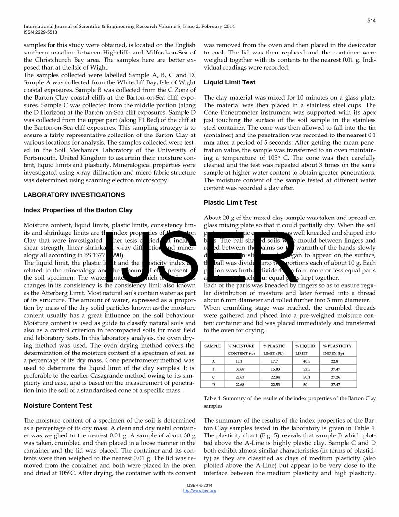
Index Properties of the Barton Clay Moisture content, liquid limits, plastic limits, consistency lim-its and shrinkage limits are the index properties of the Barton Clay that were investigated. Other tests carried out include; shear strength, linear shrinkage, x-ray diffraction and miner-alogy all according to BS 1377 (1990). The liquid limit, the plastic limit and the plasticity index are related to the mineralogy and the amount of clay present in the soil specimen. The water content at which it undergoes changes in its consistency is the consistency limit also known as the Atterberg Limit. Most natural soils contain water as part of its structure. The amount of water, expressed as a propor-tion by mass of the dry solid particles known as the moisture content usually has a great influence on the soil behaviour. Moisture content is used as guide to classify natural soils and also as a control criterion in recompacted soils for most field and laboratory tests. In this laboratory analysis, the oven dry-ing method was used. The oven drying method covers the determination of the moisture content of a specimen of soil as a percentage of its dry mass. Cone penetrometer method was used to determine the liquid limit of the clay samples. It is preferable to the earlier Casagrande method owing to its sim-plicity and ease, and is based on the measurement of penetra-tion into the soil of a standardised cone of a specific mass.
Moisture Content Test The moisture content of a specimen of the soil is determined as a percentage of its dry mass. A clean and dry metal contain-er was weighed to the nearest 0.01 g. A sample of about 30 g was taken, crumbled and then placed in a loose manner in the container and the lid was placed. The container and its con-tents were then weighed to the nearest 0.01 g. The lid was re-moved from the container and both were placed in the oven and dried at 1050C. After drying, the container with its content
was removed from the oven and then placed in the desiccator to cool. The lid was then replaced and the container were weighed together with its contents to the nearest 0.01 g. Indi-vidual readings were recorded.
Liquid Limit Test The clay material was mixed for 10 minutes on a glass plate. The material was then placed in a stainless steel cups. The Cone Penetrometer instrument was supported with its apex just touching the surface of the soil sample in the stainless steel container. The cone was then allowed to fall into the tin (container) and the penetration was recorded to the nearest 0.1 mm after a period of 5 seconds. After getting the mean pene-tration value, the sample was transferred to an oven maintain-ing a temperature of 105o C. The cone was then carefully cleaned and the test was repeated about 3 times on the same sample at higher water content to obtain greater penetrations. The moisture content of the sample tested at different water content was recorded a day after. Plastic Limit Test About 20 g of the mixed clay sample was taken and spread on glass mixing plate so that it could partially dry. When the soil paste was plastic enough, it was well kneaded and shaped into balls. The ball shaped soils were mould between fingers and rolled between the palms so the warmth of the hands slowly dried it. When slight cracks began to appear on the surface, the ball was divided into two portions each of about 10 g. Each portion was further divided into four more or less equal parts and the set of each four equal parts kept together. Each of the parts was kneaded by fingers so as to ensure regu-lar distribution of moisture and later formed into a thread about 6 mm diameter and rolled further into 3 mm diameter. When crumbling stage was reached, the crumbled threads were gathered and placed into a pre-weighed moisture con-tent container and lid was placed immediately and transferred to the oven for drying.
Table 4. Summary of the results of the index properties of the Barton Clay
samples
The summary of the results of the index properties of the Bar-ton Clay samples tested in the laboratory is given in Table 4. The plasticity chart (Fig. 5) reveals that sample B which plot-ted above the A-Line is highly plastic clay. Sample C and D both exhibit almost similar characteristics (in terms of plastici-ty) as they are classified as clays of medium plasticity (also plotted above the A-Line) but appear to be very close to the interface between the medium plasticity and high plasticity.
SAMPLE
% MOISTURE
CONTENT (w)
% PLASTIC
LIMIT (PL)
% LIQUID
LIMIT
% PLASTICITY
INDEX (Ip)
A 17.1 17.7 40.5 22.8
B 30.68 15.03 52.5 37.47
C 20.63 22.84 50.1 27.26
D 22.68 22.53 50 27.47
514
IJSER

International Journal of Scientific & Engineering Research Volume 5, Issue 2, February-2014 ISSN 2229-5518
IJSER © 2014 http://www.ijser.org
Sample A which plots above the A-Line is also a medium plas-tic clay.
Fig. 5. Plasticity Chart showing plasticity index for the Barton Clay sam-
ples Linear Shrinkage Test Linear shrinkage test was carried out to determine the per-centage linear shrinkage of the clay soil. About 150 g of the Barton Clay sample in its natural state was placed on a glass plate and thoroughly mixed with distilled water continuously until it becomes a smooth homogeneous paste at about its liq-uid limit. In order to ensure accuracy, cone penetrometer was used to obtain a penetration of 20 mm. A thin film of petrole-um jelly was added to the inner surfaces of a clean and dry mould so as to prevent the soil from sticking to the mould. The soil paste prepared was placed carefully in the mould avoiding air to be trapped so that the mould was slightly over-filled. The mould was then tapped gently to remove any air pockets. The top edge was then levelled with the aid of a pal-let knife. Soil adhering to the rim of the mould was wiped off. The mould was transferred to the oven immediately after be-ing left exposed to air so that the soil could dry slowly. The oven was initially set at 650C and after shrinkage has virtually ceased, the drying temperature was increased to 1050 C to complete the drying process. The mould and the soil were allowed to cool and the length of the soil bar was measured using engineers steel rule to obtain the final length of the spec-imen. Results obtained indicate that Samples B, C and D were curved after oven drying while Sample A was intact and showed no sign of curvature. This is probably due to the high-er plasticity of samples B, C and D when compared to A. The summary of the linear shrinkage test result is shown in Table (5).
Table 5. Summary of linkage test for the Barton Clay samples
Clay Mineralogy Test Mineralogical properties of the Barton Clay samples were car-ried out using X-Ray Diffraction test. X-Ray Diffraction is a technique used in determining the nature and proportion of clay minerals present in mudrocks. This method generally relies on the manner in which the atomic structure of the min-eral compound diffracts X-rays of certain wavelength and de-termines the arrangement of the atoms within the constituent crystals. In situation where interstratification exists within individual crystals, such as when illite and montmorillonite, or montmorillonite and kaolinite alternate at random within a single crystal, XRD yields misleading results and therefore care must be taken in the interpretation of clay minerals in such scenarios. The sample was dried and disaggregated by gently grinding with an agate pestle and mortar. A small quantity of the pow-dered clay was placed into a small beaker containing distilled water. The beaker was then placed in an ultrasonic tank for at 15 minutes to aid further disaggregation. As the grinded parti-cles may still be attached together, a deflocculating substance (NaPO3) was added. The clay suspension was transferred to a settling column (a measuring cylinder) and allowed to stand for 4 hours. The top 5 cm was pipette (2 μm suspension) and deposited on a glass slide, and allowed to dry. Three slides were prepared for each sample and placed in the X-Ray Dif-fraction Machine. Montmorillonite, illite and kaolinite groups are the most important clay minerals in geotechnical engineer-ing. Montmorillonite undergo swelling upon contact with wa-ter, whereas clay minerals of the other two groups suffer con-siderably less. The magnitude of swelling depends largely on the quantity of montmorillonite minerals. Although the rela-tive proportion of all the individual clay minerals present in Barton Clay cannot be known from qualitative XRD results only, it is obvious that the constituent clay minerals tested in the sample are mainly smectite, illite and kaolinite. However Bale (1984) has shown that smectite is relatively high in the Barton Clay at Barton (i.e. the type locality) with a remarkable abundance in the Middle Barton Beds. Smectite is usually high in the marine Eocene strata of Hampshire Basin. Whereas kao-linite, when compared to other parts of local marine Eocene strata, is fairly low. Figure (6) shows a model indicating the effect of various treatments on the 00l reflection of oriented clay samples. It can be depicted that in an air dried sample, smectite gives a characteristic d spacing and a peak respectively at 14 Ang-strom and 6.40 2θ. When treated with ethylene glycol, smectite expands thereby showing a characteristic d spacing of about 17 Angstrom and a peak at an angle of reflection of 5.10 2θ.
SAMPLE ORIGINAL
LENGTH (CM)
FINAL LENGTH
(CM)
LINEAR SHRINKAGE
(%)
A 140 130 7.14
B 140 123 12.14
C 140 122 12.8
D 140 120 14.2
515
IJSER

International Journal of Scientific & Engineering Research Volume 5, Issue 2, February-2014 ISSN 2229-5518
IJSER © 2014 http://www.ijser.org
Fig 6. The effect of various treatments on the 00l reflection of oriented
Barton Clay samples Smectite heated at 6000C gives a peak at 8.90 2θ and a d spac-ing 0f 10 Angstrom. Illite, when air-dried usually possesses a d spacing of 10 Angstrom and a reflection angle of about 8.80 2θ. The same mineral when subjected to treatment with ethylene glycol and then heated at 6000C shows no difference from the air-dried in both d spacing and reflection angle. Both air dried and ethylene glycol treated samples show kaolinite having the same properties (7 Angstrom d spacing and a peak at about 12.50 2θ) but becomes amorphous when subjected to a tem-perature of 6000 C. Fig. 7. llite/Smectite interlayering in Sam-
ple A.
Depending on the relative proportion of either of the interlay-ered minerals, illite-smectite interlayering gives a peak at an angle less than or greater than the one given by smectite (non-interlayered). Sample B (Fig. 8), Sample C (Fig. 9) and Sample D (Fig. 10) all show similar composition as they are chiefly made up of smectite, illite and kaolinite. Subsequent peaks shown by air-dried samples at greater angles imply higher orders of reflection.
Fig 8. Smectite, Illite and Kaolinite signatures in Sample B
Fig 9. Smectite, illite and Kaolinite signatures in Sample C
The effect of various treatments on the reflection of oriented clay samples00l
3 4 5 6 7 8 9 10 11 12 13 143 4 5 6 7 8 9 10 11 12 13 14
3 4 5 6 7 8 9 10 11 12 13 143 4 5 6 7 8 9 10 11 12 13 14
3 4 5 6 7 8 9 10 11 12 13 14
3 4 5 6 7 8 9 10 11 12 13 14
3 4 5 6 7 8 9 10 11 12 13 143 4 5 6 7 8 9 10 11 12 13 143 4 5 6 7 8 9 10 11 12 13 14
3 4 5 6 7 8 9 10 11 12 13 143
3 4 5 6 7 8 9 10 11 12 13 143
3 4 5 6 7 8 9 10 11 12 13 14 3 4 5 6 7 8 9 10 11 12 13 14
3 4 5 6 7 8 9 10 11 12 13 143 4 5 6 7 8 9 10 11 12 13 14
3 4 5 6 7 8 9 10 11 12 13 14
3 4 5 6 7 8 9 10 11 12 13 14
Smectite Illite Kaolinite Chlorite
3 4 5 6 7 8 9 10 11 12 13 14
3 4 5 6 7 8 9 10 11 12 13 14
3 4 5 6 7 8 9 10 11 12 13 14
3 4 5 6 7 8 9 10 11 12 13 14
AirDried
Heated@600 Cfor 1 hour
0
Treated withethylene glycol
Boiled in50% HCl(15 mins)
14 A0
17 A0
14 A0
10 A0
10 A0
10 A0
10 A0
10 A0
7 A0
7 A0
7 A0
7 A0
14 A0
14 A0
14 A0
7 A0
7 A0
dehydroxylation of hydroxide sheet
most chlorites dissolve in HCl, but Mg rich chlorites may be unaffectedhowever they are not common insedimentary rocks
ethylene glycol penetratesthe interlayer space andcauses expansion of the
spacing of the cell00l
water driven from the interlayer space
kaolinite becomes amorphous to x-rays
516
IJSER

International Journal of Scientific & Engineering Research Volume 5, Issue 2, February-2014 ISSN 2229-5518
IJSER © 2014 http://www.ijser.org
Fig 10. Smectite, Illite and Kaolinite signatures in Sample D
Clay Microfabric Test The microfabrics study of the Barton Clay was carried out us-ing the Scanning Electron Microscope (SEM). The use of imag-ing techniques has enhanced microfabric studies of soils. A typical investigation of soil microfabric was carried out by Shi et al. (1999). Scanning Electron Microscopy is an effective and convenient tool for soil microfabric studies and as a result, applied by many soil scientists to extract and analyse the physical and mechanical properties of soils. Tovey, (1980); Smart and Leng, (1993); Shi et al., (1998); Martinez-Nistal et al., (1999) have used various techniques of image analysis to de-velop quantitative relationship between SEM images and characteristic features such as porosity, permeability, fractal dimension as well as aggregate orientation. Much information regarding particle morphology in soils can also be obtained with the aid of the image analysis. However interpretations that form the basis of soil properties described above are af-fected by soil magnification and as such scale is seldom quan-titatively analysed in soil fabric studies. The clay sample was coated with a thin conductive layer and the specimen is placed within the SEM sample chamber, and placed under a va cuum. A tungsten filament is charged with between 5 and 20 kilovolts (kV) of energy, which releases a beam of electrons onto the surfaces of the sample. The elec-tron beam is focussed using electromagnets, and an image is produced on the main screen. The images were captured digi-tally onto a PC as a standard image file. Microfabrics of the four Barton Clay samples examined by the SEM are shown in Figure (21). This method shows that the samples are rich in clayey fabrics. Sample D (Fig. 11 (e)) shows the presence of a structure resembling pyrite framboids, as such an Energy Dis-persive X-ray (EDX) investigation needs to be carried out to prove whether it was pyrite. Pyrite presence in soil can be a threat to stability by causing heaving.
Fig. 11. Microfabric images of the Barton Clay Samples
Energy Dispersive X-Ray (EDX) Investigation Energy dispersive X-ray (EDX) analysis works by applying a very high energy beam of electrons from the SEM to a selected area of a sample. This high energy beam excites the electrons in the different atoms of the sample, and as these electrons move to a higher energy orbit in the atom, others fill their space. The difference in energy (in kilo electron volts, or KeV) is measured by a spectrometer in the machine, and recorded. Each element in the periodic table has unique energy levels at which its electrons change orbit, so from this the elements pre-sent can be identified in the sample. If the sample has been coated in gold-palladium for SEM imaging, then these ele-ments will also show up on the analysis. SEM examination of the samples reveals that Sample D (Figure 11 (e)) shows a crystal structure similar to pyrite. As a result, EDX technique was employed to clearly define such crystals. The image of the EDX spectrum, which shows peaks relating to the different elements that were detected in a spot analysis of the crystals which were thought to be pyrite is shown in Figure 12. The EDX supports the findings of the X-ray analyses, in that there doesn't appear to be a large amount of sulphur in the sample (as would be expected with pyrite, or iron sulphide). The main elements found were silicon and iron (with large peaks for gold and palladium - the metallic coating we added to the specimens) - a sulphur peak would be seen just to the right of the large gold (Au) peak if it were present. The crystal in ques-tion is presumably an iron mineral.
517
IJSER

International Journal of Scientific & Engineering Research Volume 5, Issue 2, February-2014 ISSN 2229-5518
IJSER © 2014 http://www.ijser.org
Fig. 12. EDX Analysis on Sample D
DISCUSSION AND CONCLUSION Mineralogical analysis of the Barton Clay samples show that they are of illite, smectite and kaolinite. Illite is characterised by silicate layers that together with strong hydrogen bonds that cannot be broken easily except when the potassium cation is removed. Clay soils composed of illites are typical of soils deposited in temperate environments where leaching is less intense. Although there is no considerable difference the ex-tent of its swelling when compared to illite, but kaolinite was found to swell to a greater extent. Both illite and kaolinite are bound by strong hydrogen bonds thereby preventing the soil from excessive degree of expansion. Kaolinite is often deposit-ed in acid tropical soils in which leaching are usually intensive around rivers that drains in regions of tropical weathering (Tucker, 1991). This finding may be suggestive of the idea that Barton Clay was influence by more acidic fresh waters. Due to the constituent silicate sheets held by weaker oxygen bonds, montmorillonite is known to be the most expansive clay of all the groups. Mixed layer illite-smectite found in sample A may form as a result of leaching of illite/mica clay from the overly-ing strata. The presence of kaolinite in the samples indicates the non water absorption capacity of the clay due to the strong hydrogen bonding of the kaolinite layer structure. The pres-ence of illites in the clay also indicates its non-expanding ca-pacity owing to the non swelling ionic structure of illites. Alt-hough, the study did not clearly indicate the nature of the ex-act member of the smectite group present, the smectites in the clay would influence its engineering behavior due to its abiliy to expand and contract with addition and removal of water. Sample A obtained from the Isle of Wight did not indicate the presence of kaolinite while the other samples from the Barton-on-Sea indicate kaolinites presence. The percentage liquid limits results from the Barton Clay samples indicated values ranging from 40.5 – 52.5 with the lowest value obtained from Sample A obtained at the Isle of Wight. This value range corresponds with ‘High’ degree of
soil expansion for the Barton Clay based on Chen (1975) classi-fication criteria for soil expansivity prediction. However this range corresponds to the Medium-High category based on the IS 1498 (1970) classification (Table 1). Percentage plasticity index for the Barton Clay samples indi-cated values ranging from 22.8 – 37.47 with the lowest value also recorded in Sample A obtained at the Isle of Wight. These values corresponds with those of (Holz and Gibbs, 1956) for soils with ‘High’ degree of expansion and ‘High-Very High’ classification based on (Chen, 1975) as well as Very High’ based on the IS 1498 (1970) (Table 2). The Barton Clay of the Isle of Wight (Sample A) also has the lowest plasticity index with Meduim plasticity (Fig. 5).Sample A obtained from the Isle of Wight is also associated with the lowest percentage moisture content value of 17.1 compared to the Samples B,C and D obtained at the Barton-on -Sea.The percentage shrink-age limit obtained for the Barton Clay indicated values rang-ing from 7.14-14.2 which corresponds to the ‘Medium’ classsi-fication based on Holtz and Gibbs, (1956). REFERENCES
[1] Aubry, M. P. (1986). Palaeogene calcareous nanoplakton
biostratigraphy of northwestern Europe. Palaeogeography,
Palaeoclimatology, Palaeocology , 55:267-334.
[2] Barton, M. E. (1973). The degradation of Barton Clay Cliffs of
Hampshire. Quaterly Journal of Engineering Geology and Hydrogeology,
423-440.
[3] Barton, M. E., Hillier, S., & Watson, G. (2006). The slip surface in the
D Zone of Barton Clay. Quaterly Journal of Engineering Geology and
Hydrogeology , 357-370.
[4] Bristow, H. W., Reid, C., & Strahan, A. (1889). Geology of the Isle of
Wight. Memoirs of the Geological Survey of the United Kingdom .
[5] BS 1377-7. (1990). Methods of test for Soils for Civil Engineering
Purposes. London: British Standard Institute.
[6] Burton, E. S. (1933). Faunal horizons of the Barton Beds in
Hampshire. Proc. Geol. Assoc. , 44,131-163.
[7] Chen, F. (1975). Foundations on Expansive Soils. Amsterdam: Elsevier.
[8] Curry, D., Dalley, B., Edwards, N., Middlemiss, F. A., Stinton, F. C.,
& Wright, C. W. (1972). The Isle of Wight. geologists Association Guide,
No 25.
[9] Daley, B. (1998). Palaeogene sections in the Isle of Wight. A revision
of their description and significance in the light of research
undertaken over recent decades. Tertiary Research .
[10] Day, R. W. (1994). Swell-shrink behaviour of compacted clay. ASCE
Journal of Geotechnical Engineering , 618-623.
[11] Edwards, R. A., & Freshney. (1987). Lithostratigraphical
classification of Hampshire Basin Palaeogene Deposits (Reading
Formation and Headon Hill Formation). Tertiary Research , 8,43-73.
[12] Fort, D. S., Clark, A. R., & Cliffe, D. G. (2000). The investigation and
monitoring of landslides at Barton on Sea, Hampshire, UK. London: High
518
IJSER

International Journal of Scientific & Engineering Research Volume 5, Issue 2, February-2014 ISSN 2229-5518
IJSER © 2014 http://www.ijser.org
Point Rendel.
[13] Gardner, J., Keeping, H., & Monkton, H. (1888). The Upper Eocene
comprising the Barton and Upper Bagshot Beds. Quaterly Journal of
the Geological Society of London , 44,578-635.
[14] Gourley, C. S., Newill, D., & Shreiner, H. D. (1993). Expansive ssoils.
Proceedings of the first international symposium on enginering
characteristics of arid soils (pp. 109-121). TRL's reseach strategy.
[15] Graham, J., & Houlsby, G. (1983). anisotrpic elasticity of a natural
clay. Geotechnique , 164-180.
[16] Harland , W.B., Cox, A.V., Llewellyn, P.G., Pickton, C.A.G., Smith,
A.G. and Walters, R. 1982. A Geologic Time Scale. Cambridge
University Press, Cambridge.
[17] Holtz, W. G., & Gibbs, H. J. (1956). Engineering properties of
expansive soils. Transactions of ASCE , 121:641-663.
[18] Hugget, J. M., & Gale, A. S. (1997). Petrology and
palaeoenvironmental significance of glaucony in the Eocene
succession at Whitecliff Bay, Hampshire Basin, UK. Journal of the
Geological Society of London, 154:897-912.
[19] IS 1498:1970 (R2002) Classification and Identification Of Soils For
General Engineering Purposes.
[20] Martinez-Nistal, A., Vaniale, F., Setti, M., & Coteccia, F. (1999). A
scanning electron microscopy image processing method for
quantifying fabric orientation of clay geomaterials. Applied Clay
Science , 14;235-243.
[21] Melville, R. V and Freshney (1982). The Hampshire Basin and adjoining
areas. London: Institute of Geological Sciences.
[22] Murray, J. W., & Right, C. A. (1974). Palaeogene Foraminifera and
Palaeoecology, Hampshire and Paris Basins and the English
Channel. Palaeontology , 14,1-29.
[23] Osipov, V. I., Bik, N. N., & Rumjantseva, N. A. (1987). Cyclic
swelling of clays. Applied Clay Science , 363-374.
[24] Plint, A. G. (1982). Eocene sedimentation and tectonics in the
Hampshire Basin. Journal of the Geological Society of London , 139,239-
254.
[25] Popesco, M. (1980). Behaviour of expansive soils with crumb
structure. 4th International Conference on Expansive soils, (pp. 158-171).
Denver, CO.
[26] Rendel Geotechnics. (1998). Barton on Sea cliff stabilization, monitoring
of ground movement and groundwater, 1991-1997. New Forest District.
[27] Shi, B., Mukarami, Y., & Wu, Z. (1998). Orientation of aggregate of
fine grained soil:Quantification and Application. Eng. Geol. , 50;59-
70.
[28] Shi, B., Wu, Z., Inyang, H. I., Chen, J., & Wang, B. (1999). Preparation
of soil specimen for SEM analysis using freeze-cut-drying. Bull. Int.
Assoc. Eng. Geol. Environ. , 58; 1-7.
[29] Skempton, A. W., & Hutchinson, J. N. (1969). Stability of natural
slopes and embankment foundations. Proceedings of the 7th
International Conference on Soil Mechanics and Foundations Engineering
(pp. 291-340). Mexico City: State of Art.
[30] Skempton, A. W., & LaRochelle. (1965). The Bradwell Slip:A Short
term Failure in London Clay. Geotechnique , 221-242.
[31] Smart, P., & Leng, X. (1993). Present developments in image
analysis. Scanning Microsc , 7; 5-16.
[32] Sridharan, A., & Prakash, K. (2000). Classification procedure for
expansive clays. Proc. Instn Civ. Engng. , 235-240.
[33] Tovey, N. K. (1980). A digital computer technique for orientation
analysis for micrograph of soil fabric. J. Microsc , 120; 303-315.
[34] Tucker, M. (1991). Techniques in Sedimentology. London: Blackwell
Scientific Publications.
[35] Van Auken, F. M. (1963). Shear strength of clay-shales found in the
southwestern USA . Soil Mechanics and Foundations , 255-287.
[36] White, H. J. (1921). A short account of the Geology of the Isle of
Wight. Memoirs of the Geological Survey of Great Britain.
519
IJSER