Geosynthetic Engineering: Geosynthetic Separators Engineering... · Geosynthetic Engineering:...
44
Geosynthetic Engineering: Geosynthetic Separators Course No: G04-005 Credit: 4 PDH Yun Zhou, PhD, PE Continuing Education and Development, Inc. 9 Greyridge Farm Court Stony Point, NY 10980 P: (877) 322-5800 F: (877) 322-4774 [email protected]
-
Upload
phamkhuong -
Category
Documents
-
view
238 -
download
0
Transcript of Geosynthetic Engineering: Geosynthetic Separators Engineering... · Geosynthetic Engineering:...

Geosynthetic Engineering: Geosynthetic Separators Course No: G04-005
Credit: 4 PDH
Yun Zhou, PhD, PE
Continuing Education and Development, Inc. 9 Greyridge Farm Court Stony Point, NY 10980 P: (877) 322-5800 F: (877) 322-4774 [email protected]

5.0 GEOSYNTHETICS IN ROADWAYS AND PAVEMENTS
5.1 INTRODUCTION
The most common use of geosynthetics is in road and pavement construction. Geotextiles increase
stability and improve performance of weak subgrade soils primarily by separating the aggregate from the subgrade. In addition, geogrids and some geotextiles can provide strength through
friction or interlock developed between the aggregate and the geosynthetic. Geotextiles can also
provide filtration and drainage by allowing excess pore water pressures in the sub grade to dissipate
into the aggregate base course and, in cases of poor-quality aggregate, through the geotextile plane
itself.
In this chapter, each of the geosynthetic functions will be discussed and related to design concepts
and performance properties. Selection, specification, and construction procedures will also be
presented.
5.1-1 Functions of Geosynthetics in Roadways and Pavements
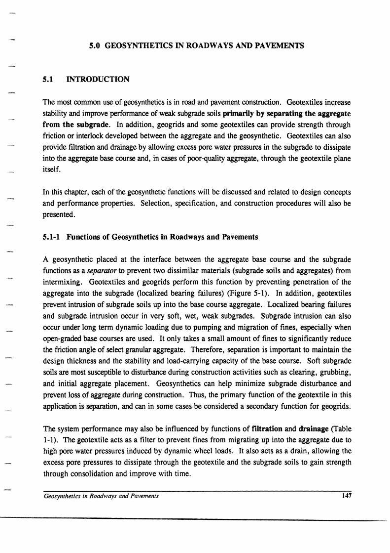
A geosynthetic placed at the interface between the aggregate base course and the subgrade
functions as a separator to prevent two dissimilar materials (subgrade soils and aggregates) from
intermixing. Geotextiles and geogrids perform this function by preventing penetration of the
aggregate into the subgrade (localized bearing failures) (Figure 5-1). In addition, geotextiles
prevent intrusion of subgrade soils up into the base course aggregate. Localized bearing failures
and subgrade intrusion occur in very soft, wet, weak subgrades. Subgrade intrusion can also
occur under long term dynamic loading due to pumping and migration of fines, especially when
open-graded base courses are used. It only takes a small amount of fines to significantly reduce
the friction angle of select granular aggregate. Therefore, separation is important to maintain the
design thickness and the stability and load-carrying capacity of the base course. Soft sub grade
soils are most susceptible to disturbance during construction activities such as clearing, grubbing,
and initial aggregate placement. Geosynthetics can help minimize sub grade disturbance and
prevent loss of aggregate during construction. Thus, the primary function of the geotextile in this
application is separation, and can in some cases be considered a secondary function for geogrids.
The system performance may also be influenced by functions of filtration and drainage (Table 1-1). The geotextile acts as a filter to prevent fines from migrating up into the aggregate due to
high pore water pressures induced by dynamic wheel loads. It also acts as a drain, allowing the
excess pore pressures to dissipate through the geotextile and the subgrade soils to gain strength
through consolidation and improve with time.
Geosynthetics in Roadways and Pavements 147

"0 (I) CIl (I) e:: Q) Ole::
0- ..y. (I) 0 CIl 0_
Cl..c
Figure 5-1
Soft subgrade ... Soft subgrode
Concept of geotextile separation in roadways (after Rankilor, 1981).
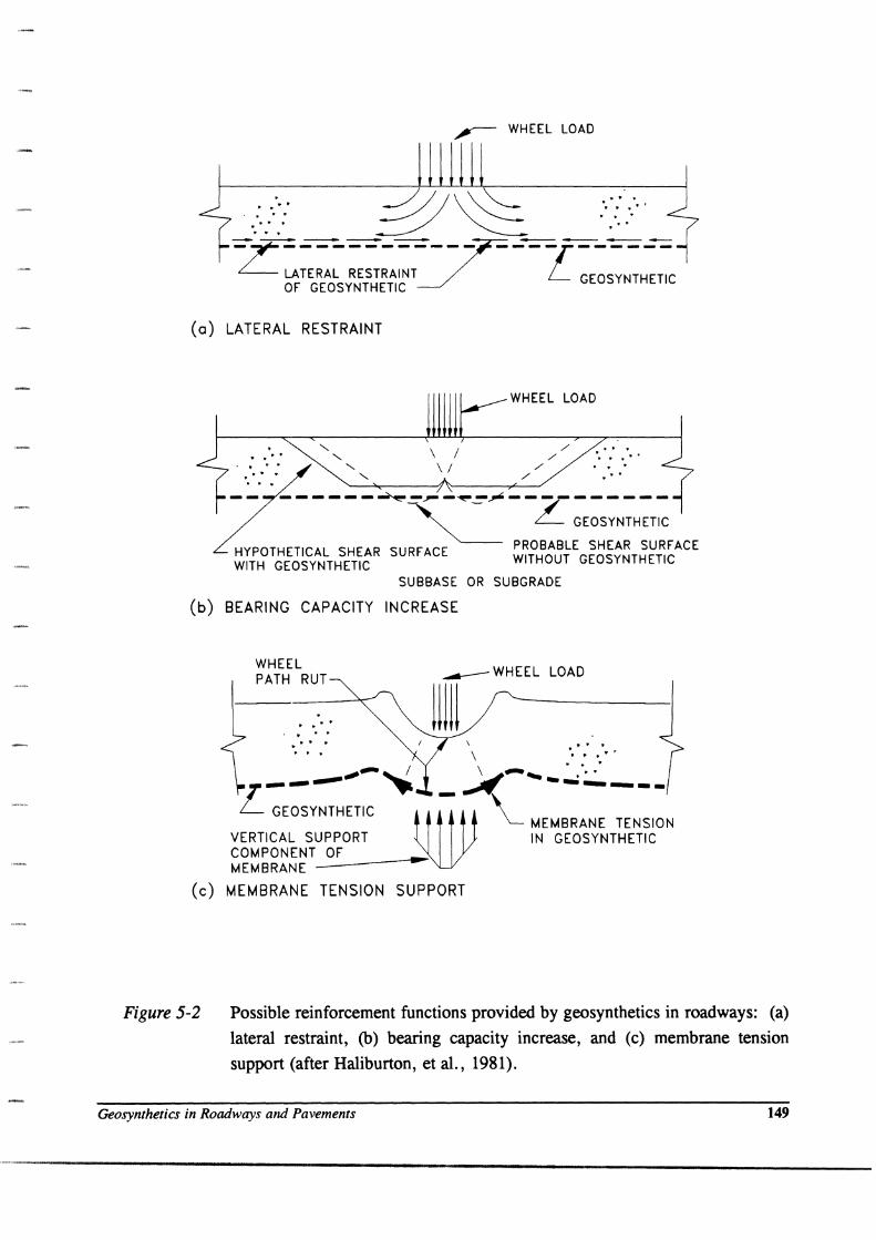
System perfonnance may also be improved through reinforcement. Geogrids and geotextiles
provide reinforcement through three possible mechanisms.
1. Lateral restraint of the base and subgrade through friction and interlock between the
aggregate, soil and the geosynthetic (Figure 5-2a).
2. Increase in the system bearing capacity by forcing the potential bearing capacity failure surface
to develop along alternate, higher shear strength surfaces (Figure 5-2b).
3. Membrane suppon of the wheel loads (Figure 5-2c).
When an aggregate layer is loaded by a wheel or track, the aggregate tends to move or shove
laterally, as shown in Figure 5-2a, unless it is restrained by the subgrade or geosynthetic
reinforcement. Soft, weak subgrade soils provide very little lateral restraint, so when the
aggregate moves laterally, ruts develop on the aggregate surface and also in the subgrade. A
geogrid with good interlocking capabilities or a geotextile with good frictional capabilities can
provide tensile resistance to lateral aggregate movement. Another possible geosynthetic
reinforcement mechanism is illustrated in Figure 5-2b. Using the analogy of a wheel load to a
footing, the geosynthetic reinforcement forces the potential bearing capacity failure surface to
follow an alternate higher strength path. This tends to increase the bearing capacity of the
roadway.
148 April 1998
,-- WHEEL LOAD
(0) LATERAL RESTRAINT
. . . . . . .. . ' . \ / \ /
WHEEL LOAD
/ ./ 9" .... ..
./ .... . /
------~-~-~-~----------~ L GEOSYNTHETIC
HYPOTHETICAL SHEAR SURFACE PROBABLE SHEAR SURFACE WITH GEOSYNTHETIC WITHOUT GEOSYNTHETIC
SUBBASE OR SUBGRADE
(b) BEARING CAPACITY INCREASE
(c)
Figure 5-2
WHEEL PATH RUT
. . . . . . . . .. .. " to . . .
LOAD
.' . \ "" .. .. ....
,,--~ ~\ ----_.:.: Z-_........ -----GEOSYNTHETIC llilV- MEMBRANE TENSION
VERTICAL SUPPORT IN GEOSYNTHETIC COMPONENT OF .-MEMBRANE
MEMBRANE TENSION SUPPORT
Possible reinforcement functions provided by geosynthetics in roadways: (a)
lateral restraint, (b) bearing capacity increase, and (c) membrane tension
support (after Haliburton, et al., 1981).
Geosynthetics in Roadways and Pavements 149
A third possible geosynthetic reinforcement function is membrane-type support of wheel loads,
as shown conceptually in Figure 5-2c. In this case, the wheel load stresses must be great enough
to cause plastic deformation and ruts in the subgrade. If the geosynthetic has a sufficiently high
tensile modulus, tensile stresses will develop in the reinforcement, and the vertical component of
this membrane stress will help support the applied wheel loads. As tensile stress within the
geosynthetic cannot be developed without some elongation, wheel path rutting (in excess of 100
mm) is required to develop membrane-type support. Therefore, this mechanism is generally
limited to temporary roads or the first aggregate lift in permanent roadways.
5.1-2 Subgrade Conditions in which Geosynthetics are Useful
Geotextile separators have a 20 + year history of successful use for the stabilization of very soft
wet subgrades. Based on experience and several case histories summarized by Haliburton,
Lawmaster, and McGuffey (1981) and Christopher and Holtz (1985), the following subgrade
conditions are considered to be the most appropriate for geosynthetic use in roadway construction:
• Poor soils (USCS: SC, CL, CH, ML, MH, OL, OH, and PT)
(AASHTO: A-5, A-6, A-7-5, and A-7-6)
• Low undrained shear strength
t f = Cu < 90 kPa
CBR < 3
MR ::: 30MPa
• High water table
• High sensitivity
{Note: CBR as determined with ASTM D 4429 Bearing
Ratio of Soils in Place (1994)}
Under these conditions, geosynthetics function primarily as separators and filters to stabilize the
subgrade, improving construction conditions and allowing long-term strength improvements in the
subgrade. If large ruts develop during placement of the first aggregate lift, then some reinforcing
effect is also present. As a summary recommendation, the following geotextile functions are
appropriate for the corresponding subgrade strengths:
Undrained Shear
Stren~th (kPa)
60 - 90
30 - 60 < 30
Sub~rade
eBB. 2-3
1 - 2
< 1
Functions
Filtration and possibly separation
Filtration, separation, and possibly reinforcement
All functions, including reinforcement
As the geosynthetic allows for subgrade improvement with time, AASHTO M288 has identified
applications where the undrained shear strength is less than about 90 kPa (CBR about 3) as
ISO April 1998
stabilization applications. From a foundation engineering point of view, clay soils with undrained
shear strengths of 90 kPa are considered to be stiff clays (Terzaghi and Peck, 1967, P 30) and are
generally quite good foundation materials. Allowable footing pressures on such soils equal 150
kPa or greater. Simple stress distribution calculations show that for static loads, such soils will
readily support reasonable truck loads and tire pressures, even under relatively thin granular bases.
Dynamic loads and high tire pressures are another matter. Some rutting will probably occur in
such soils, especially after a few hundred passes (Webster, 1993). If traffic is limited, as it is in
many temporary roads, or if shallow « 75 mm) ruts are acceptable, as in most construction
operations, then a maximum undrained shear strength of about 90 kPa (CBR = 3) for geosynthetic
use in highway construction seems reasonable. However, for soils that are seasonally weak (e.g.,
from frost heave) or for high fines content soils which are susceptible to pumping, a geotextile
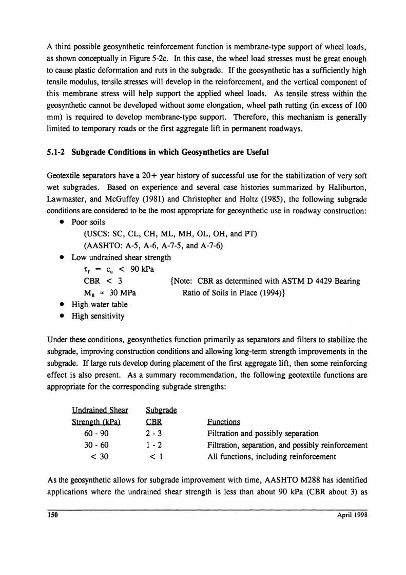
separator may be of benefit in preventing migration of fines. This is especially the case for
permeable base applications. Even on firm subgrades, a geotextile placed beneath the base
functions as a separator and filter, as illustrated in Figure 5-3. A greater range of geotextile
applicability is recognized in the M288 specification (AASHTO, 1997) with a CBR ~ 3 the
geotextile application is identified as separation. Further discussion of potential applicability of
geotextiles on soils with CBR > 3 is presented in Appendix G of this manual, and the complete
M288 specification is presented in Appendix D .
., .' • • ., •. • t. • • ., .
• ' •• ' .~., "'I"'~ '0.;' " '0' ~. " I' • " .' • ': "', .,,' fO, ' •• ' .,'
• • ., I • • to t' ..• . • • • ': • .'" •
. , . .' . ",
,.' ........ • \. ".'...., • • I, 0"
, "" , •. .", PCC Pavement .'.",', , .. .: ~," ,.':. " ", '.' . ,.", ' . , .' ., ". . :. .' .. "
• ., , ". • .' • , '.' • I.. • ., '. "':".:;'" • ',.. • '.
,l' t' ••• ,. ,", '.' •• ~'" :,: ".
Figure 5-3 Geotextile separator beneath permeable base (Baumgartner, 1994).
Geosynthetics in Roadways and Pavements lSI
5.2 APPLICATIONS
5.2-1 Temporary and Pennanent Roads
Roads and highways are broadly classified into two categories: permanent and temporary,
depending on their service life, traffic applications, or desired performance. Permanent roads
include both paved and unpaved systems which usually remain in service 10 years or more.
Permanent roads may be subjected to more than a million load applications during their design
lives. On the other hand, temporary roads are, in most cases, unpaved. They remain in service
for only short periods of time (often less than 1 year), and are usually subjected to fewer than
10,000 load applications during their services lives. Temporary roads include detours, haul and
access roads, construction platforms, and stabilized working tables required for the construction
of permanent roads, as well as embankments over soft foundations.
Geosynthetics allow construction equipment access to sites where the soils are normally too weak
to support the initial construction work. This is one of the more important uses of geosynthetics.
Even if the finished roadway can be supported by the subgrade, it may be virtually impossible to
begin construction of the embankment or roadway. Such sites require stabilization by dewatering,
demucking, excavation and replacement with select granular materials, utilization of stabilization
aggregate, chemical stabilization, etc. Geosynthetics can often be a cost-effective alternate to
these expensive foundation treatment procedures.
Furthermore, geosynthetic separators enable contractors to meet minimum compaction
specifications for the first two or three aggregate lifts. This is especially true on very soft, wet
subgrades, where the use of ordinary compaction equipment is very difficult or even impossible.
Long term, a geosynthetic acts to maintain the roadway design section and the base course
material integrity. Thus, the geosynthetic will ultimately increase the life of the roadway.
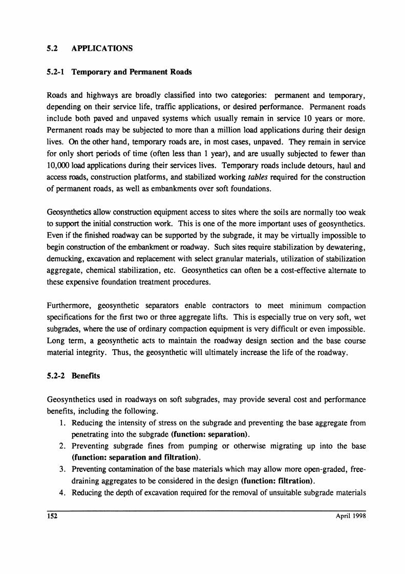
5.2-2 Benefits
Geosynthetics used in roadways on soft subgrades, may provide several cost and performance
benefits, including the following.
152
1. Reducing the intensity of stress on the subgrade and preventing the base aggregate from
penetrating into the sub grade (function: separation). 2. Preventing subgrade fines from pumping or otherwise migrating up into the base
(function: separation and filtration). 3. Preventing contamination of the base materials which may allow more open-graded, free
draining aggregates to be considered in the design (function: filtration). 4. Reducing the depth of excavation required for the removal of unsuitable subgrade materials
April 1998

(function: separation and reinforcement). 5. Reducing the thickness of aggregate required to stabilize the subgrade (function:
separation and reinforcement). 6. Reducing disturbance of the subgrade during construction (function: separation and
reinforcement) . 7. Allowing an increase in subgrade strength over time (function: filtration). 8. Reducing the differential settlement of the roadway, which helps maintain pavement
integrity and uniformity (function: reinforcement). Geosynthetics will also aid in
reducing differential settlement in transition areas from cut to fill. {NOTE: Total and
consolidation settlements are not reduced by the use of geosynthetic reinforcement.}
9. Reducing maintenance and extending the life of the pavement (functions: all).
Geosynthetics are also used in permanent roadways to provide capillary breaks to reduce frost
action in frost-susceptible soils, and to provide membrane-encapsulated soil layers (MESL) to
reduce the effects of seasonal water content changes on roadways on swelling clays.
5.3 POSSmLE FAILURE MODES OF PERMANENT ROADS
Yoder and Witczak (1975) define two types of pavement distress, or failure. The first is a
structural failure, in which a collapse of the entire structure or a breakdown of one or more of the
pavement components renders the pavement incapable of sustaining the loads imposed on its
surface. The second type failure is a functional failure; it occurs when the pavement, due to its
roughness, is unable to carry out its intended function without causing discomfort to drivers or
passengers or imposing high stresses on vehicles. The cause of these failure conditions may be
due to excessive loads, climatic and environmental conditions, poor drainage leading to poor
subgrade conditions, and disintegration of the component materials. Excessive loads, excessive
repetition of loads, and high tire pressures can cause either structural or functional failures.
Pavement failures may occur due to the intrusion of subgrade soils into the granular base, which
results in inadequate drainage and reduced stability. Distress may also occur due to excessive
loads that cause a shear failure in the subgrade, base course, or the surface. Other causes of
failures are surface fatigue and excessive settlement, especially differential of the subgrade.
Volume change of subgrade soils due to wetting and drying, freezing and thawing, or improper
drainage may also cause pavement distress. Inadequate drainage of water from the base and
subgrade is a major cause of pavement problems (Cedergren, 1987). If the subgrade is saturated,
excess pore pressures will develop under traffic loads, resulting in subsequent softening of the
subgrade. Under dynamic loading, fines can be literally pumped up into the subgrade or base.
Geosynthetics in Roadways and Pavemellts 153
Improper construction practices may also cause pavement distress. Wetting of the subgrade during
construction may permit water accumulation and subsequent softening of the subgrade in the rutted
areas after construction is completed. Use of dirty aggregates or contamination of the base
aggregates during construction may produce inadequate drainage, instability, and frost
susceptibility. Reduction in design thickness during construction due to insufficient subgrade
preparation may result in undulating subgrade surfaces, failure to place proper layer thicknesses,
and unanticipated loss of base materials due to subgrade intrusion. Yoder and Witczak (1975)
state that a major cause of pavement deterioration is inadequate observation and field control by
qualified engineers and technicians during construction.
After construction is complete, improper or inadequate maintenance may also result in pavement
distress. Sealing of cracks and joints at proper intervals must be performed to prevent surface
water infiltration. Maintenance of shoulders will also affect pavement performance.
As indicated in the list of possible benefits resulting from geosynthetic use in permanent roadway
systems (section 5.2-2), properly designed geosynthetics can enhance pavement performance and
reduce the likelihood of failures.
5.4 ROADW A Y DESIGN USING GEQTEXTILES
Certain design principles are common to all types of roadways, regardless of the design method.
Basically, the design of any roadway involves a study of each of the components of the system,
(surface, aggregate base courses and subgrade) detailing their behavior under traffic load and their
ability to carry that load under various climatic and environmental conditions. All roadway
systems, whether permanent or temporary, derive their support from the underlying subgrade
soils. Thus, the geotextile functions are similar for either temporary or permanent roadway
applications. However, due to different performance requirements, design methodologies for temporary roads should not be used to design permanent roads. Temporary roadway design
usually allows some rutting to occur over the design life, as ruts will not necessarily impair
service. Obviously, ruts are not acceptable in permanent roadways. In the following two
sections, recommended design procedures for both temporary and permanent roads are presented.
Our permanent road and pavement design basically uses geotextiles for the construction or
stabilization lift only; the base course thickness required to adequately carry the design traffic
loads for the design life of the pavement is not reduced due to the use of a geotextile. There is
some evidence, however, that suggests a geogrid placed at the bottom of the aggregate base may
permit a 10 to 20% base thickness reduction, as noted in Appendix 0, Recent Roadway Research.
154 April 1998
5.5 GEOTEXTILE SURVIVABILITY
Selecting a geotextile for either permanent or temporary roads depends upon one thing -- the
survivability criteria. If the roadway system is designed correctly, then the stress at the top of the
subgrade due to the weight of the aggregate and the traffic load should be less than the bearing
capacity of the soil plus a safety factor. However, the stresses applied to the subgrade and the
geotextile during construction may be much greater than those applied in service. Therefore,
selection of the geotextile in roadway applications is usually governed by the anticipated
construction stresses. This is the concept of geotextile survivability -- the geotextile must survive
the construction operations if it is to perform its intended function.
The geotextile strength required to survive the most severe conditions anticipated during
construction is listed in Table 5-1 (a Class 1 geotextile per AASHTO M288 (1997». Geotextiles
that meet or exceed these survivability requirements can be considered acceptable for most
projects. The selected geotextile must also retain the underlying subgrade soils, allowing the
subgrade to drain freely, consolidate, and gain strength. Thus, the geotextile must be checked,
using the drainage and filtration requirements discussed in Chapter 2. Default geotextile
requirements are presented in Table 5-1.
The survivability requirements in Table 5-1 were based on both research and on the properties of
geotextiles which have performed satisfactorily as separators in roads and in similar applications.
In the absence of any other information, they should be used as minimum property values.
Judgment and experience may be used to reduce the geotextile requirements as indicated by
AASHTO M288.
Geotextiles with less survivability strength (i.e., a Class 2 geotextile per AASHTO M288 (1997»
may be acceptable for applications where a moderate level of survivability is needed. Table 5-2
relates the elements of construction (i.e., equipment, aggregate characteristics, subgrade
preparation, and subgrade shear strength) to the severity of the loading imposed on the geotextile.
If one or more of these items falls within a particular severity category (i.e., moderate or high),
then geotextiles meeting those survivability requirements should be selected. A Class 1 geotextile
should be used for the high category, and a Class 2 geotextile may be considered for the moderate
category. Variable combinations indicating a NOT RECOMMENDED rating suggests that one
or more variables should be modified to assure a successful installation. Some judgment is
required in using these criteria.
Geosynthetics in Roadways and Pavements 155
Property
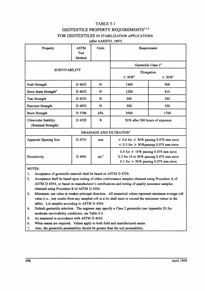
TABLE 5-1
GEOTEXTILE PROPERTY REQUIREMENTS t ,2,3
FOR GEOTEXTILES IN ST ABILIZA TION APPLICATIONS
(after AASHTO, 1997)
ASTM Units Requirement
Test
Method
Geotextile Class 14
SURVIVABILITY Elongation
< 50%5 > 50%5
Grab Strength D 4632 N 1400 900
Sewn Seam Strength6 D 4632 N 1200 810
Tear Strength D4533 N 500 350
Puncture Strength D4833 N 500 350
Burst Strength D 3786 kPa 3500 1700
Ultraviolet Stability D4355 % 50 % after 500 hours of exposure
(Retained Strength)
DRAINAGE AND FILTRATION7
Apparent Opening Size D 4751 mm < 0.6 for < 50% passing 0.075 mm sieve
< 0.3 for> 50 % passing 0.075 mm sieve
0.5 for < 15 % passing 0.075 mm sieve
Penni ttivity D 4491 sec-1 0.2 for 15 to 50% passing 0.075 mm sieve
0.1 for> 50% passing 0.075 mm sieve
NOTES:
1. Acceptance of geotextile material shall be based on ASTM D 4759.
2. Acceptance shall be based upon testing of either conformance samples obtained using Procedure A of
ASTM D 4354, or based on manufacturer's certifications and testing of quality assurance samples
obtained using Procedure B of ASTM D 4354.
3. Minimum; use value in weaker principal direction. All numerical values represent minimum average roll
value (i.e., test results from any sampled roll in a lot shall meet or exceed the minimum values in the
table). Lot samples according to ASTM D 4354.
4. Default geotextile selection. The engineer may specify a Class 2 geotextile (see Appendix D) for
moderate survivability conditions, see Table 5-2.
5. As measured in accordance with ASTM D 4632.
6. When seams are required. Values apply to both field and manufactured seams.
7. Also, the geotextile permeability should be greater than the soil permeability.
156 April 1998
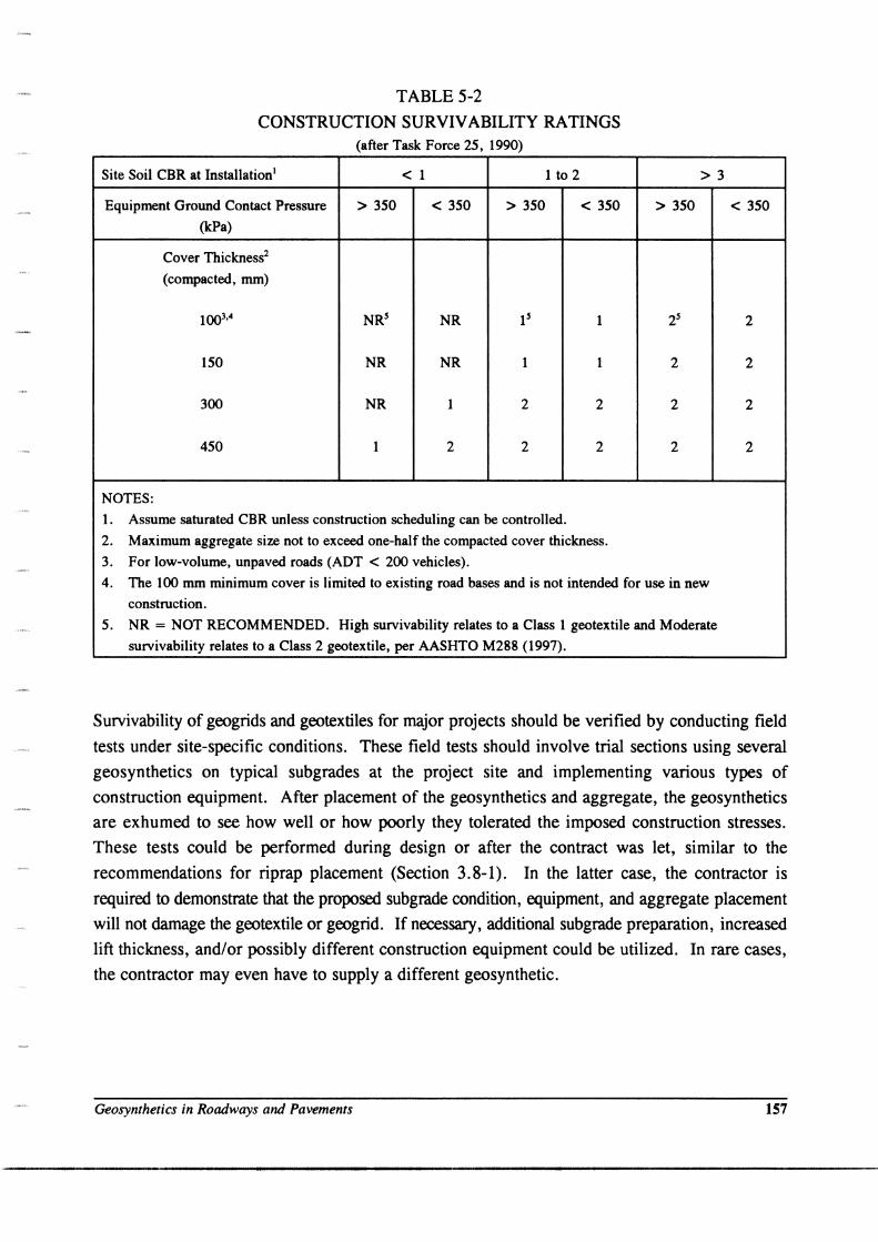
TABLE 5-2
CONSTRUCTION SURVIVABILITY RATINGS (after Task Force 25, 1990)
Site Soil CBR at Installation l
Equipment Ground Contact Pressure
(kPa)
NOTES:
Cover Thickness2
(compacted, mm)
150
300
450
> 350
NR
NR
1
< 1 1 to 2
< 350 > 350
NR
NR 1
1 2
2 2
1. Assume saturated CBR unless construction scheduling can be controlled.
< 350
1
1
2
2
2. Maximum aggregate size not to exceed one-half the compacted cover thickness.
3. For low-volume, unpaved roads (ADT < 200 vehicles).
> 3
> 350
2
2
2
4. The 100 mm minimum cover is limited to existing road bases and is not intended for use in new
construction.
5. NR = NOT RECOMMENDED. High survivability relates to a Class 1 geotextile and Moderate
survivability relates to a Class 2 geotextile, per AASHTO M288 (1997).
< 350
2
2
2
2
Survivability of geogrids and geotextiles for major projects should be verified by conducting field
tests under site-specific conditions. These field tests should involve trial sections using several
geosynthetics on typical subgrades at the project site and implementing various types of
construction equipment. After placement of the geosynthetics and aggregate, the geosynthetics
are exhumed to see how well or how poorly they tolerated the imposed construction stresses.
These tests could be performed during design or after the contract was let, similar to the
recommendations for riprap placement (Section 3.8-1). In the latter case, the contractor is
required to demonstrate that the proposed subgrade condition, equipment, and aggregate placement
will not damage the geotextile or geogrid. If necessary, additional subgrade preparation, increased
lift thickness, and/or possibly different construction equipment could be utilized. In rare cases,
the contractor may even have to supply a different geosynthetic.
Geosynthetics in Roadways and Pavements 157
----_.----------------------------------------------------------------------------------

5.6 DESIGN GUIDELINES FOR TEMPORARY AND UNPAVED ROADS
There are two main approaches to the design of temporary and unpaved roads. The first assumes
no reinforcing effect of the geotextile; that is, the geotextile acts as a separator only. The second
approach considers a possible reinforcing effect due to the geotextile. It appears that the
separation function is more important for thin roadway sections with relatively small live loads
where ruts, approximating 50 to 100 mm are anticipated. In these cases, a design which assumes
no reinforcing effect is generally conservative. On the other hand, for large live loads on thin
roadways where deep ruts (> 100 mm) may occur, and for thicker roadways on softer subgrades,
the reinforcing function becomes increasingly more important if stability is to be maintained. It
is for these latter cases that reinforcing analyses have been developed and are appropriate.
The design method presented in this manual considers mainly the separation and filtration
functions. It was selected because it has a long history of successful use, it is based on principles
of soil mechanics, and it has been calibrated by full-scale field tests. It can also be adapted to a
wide variety of conditions. Other methods considering reinforcement functions are described by
Koerner (1994), Christopher and Holtz (1985) and Giroud and Noiray (1981). For roadways
where stability of the embankment foundation is questionable (i.e., (yH)/c > 3), refer to Chapter
7 for information on reinforced embankments.
The following design method was developed by Steward, Williamson, and Mohney (1977) for the
U.S. Forest Service (USFS). It allows the designer to consider:
• vehicle passes;
• equivalent axle loads;
• axle configurations;
• tire pressures;
• sub grade strengths; and
• rut depths.
The following limitations apply:
• the aggregate layer must be a) compacted to CBR 80,
b) cohesion less (nonplastic);
• vehicle passes less than 10,000; • geotextile survivability criteria must be considered; and • subgrade undrained shear strength less than about 90 kPa (CBR < 3).
As discussed in Section 5.1-2, for subgrades stronger than about 90 kPa (CBR > 3), geotextiles
are rarely required for stabilization, although they may provide some drainage and filtration. In
158 April 1998
this case, the principles developed in Chapter 2 are applicable, just as they are for weaker
subgrades where drainage and filtration are likely to be very important.
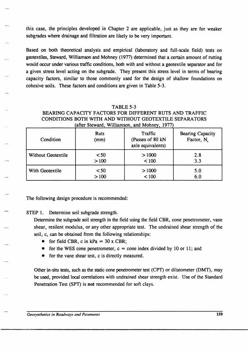
Based on both theoretical analysis and empirical (laboratory and full-scale field) tests on
geotextiles, Steward, Williamson and Mohney (1977) determined that a certain amount of rutting
would occur under various traffic conditions, both with and without a geotextile separator and for
a given stress level acting on the subgrade. They present this stress level in terms of bearing
capacity factors, similar to those commonly used for the design of shallow foundations on
cohesive soils. These factors and conditions are given in Table 5-3.
TABLE 5-3 BEARING CAPACITY FACTORS FOR DIFFERENT RUTS AND TRAFFIC CONDITIONS BOTH WITH AND WITHOUT GEOTEXTILE SEPARATORS
after Steward, Williamson and Mohney, 1977
Ruts Traffic Bearing Capacity Condition (mm) (Passes of 80 kN Factor, Nc
axle equivalents)
Without Geotextile <50 >1000 2.8 > 100 < 100 3.3
With Geotextile <50 >1000 5.0 > 100 < 100 6.0
The following design procedure is recommended:
STEP 1. Determine soil subgrade strength.
Detennine the subgrade soil strength in the field using the field CBR, cone penetrometer, vane
shear, resilent modulus, or any other appropriate test. The undrained shear strength of the
soil, c, can be obtained from the following relationships:
• for field CBR, c in kPa = 30 x CBR;
• for the WES cone penetrometer, c = cone index divided by 10 or 11; and
• for the vane shear test, c is directly measured.
Other in-situ tests, such as the static cone penetrometer test (CPT) or dilatometer (DMT), may
be used, provided local correlations with undrained shear strength exist. Use of the Standard
Penetration Test (SPT) is not recommended for soft clays.
Geosynthetics in Roadways and Pavements 159
STEP 2. Determine subgrade strength at several locations and at different times of the year.
Make strength determinations at several locations where the subgrade appears to be the
weakest. Strengths should be evaluated at depth of 0 to 200 mm and from 200 - 500 mm; six
to ten strength measurements are recommended at each location to obtain a good average
value. Tests should also be performed when the soils are in their weakest condition, when the
water table is the highest, etc.
STEP 3. Determine wheel loading.
Determine the maximum single wheel load, maximum dual wheel load, and the maximum dual
tandem wheel load anticipated for the roadway during the design period. For example, an
8 m3 dump truck with tandem axles will have a dual wheel load of approximately 35 kN. A
motor grader has a wheel load of 22 to 44 kN.
STEP 4. Estimate amount of traffic.
Estimate the maximum amount of traffic anticipated for each design vehicle class.
STEP 5. Establish tolerable rutting.
Establish the amount of tolerable rutting during the design life of the roadway. For example,
50 to 75 mm of rutting is generally acceptable during construction.
STEP 6. Obtain bearing capacity factor.
Obtain appropriate subgrade stress level in terms of the bearing capacity factors in Table 5-3.
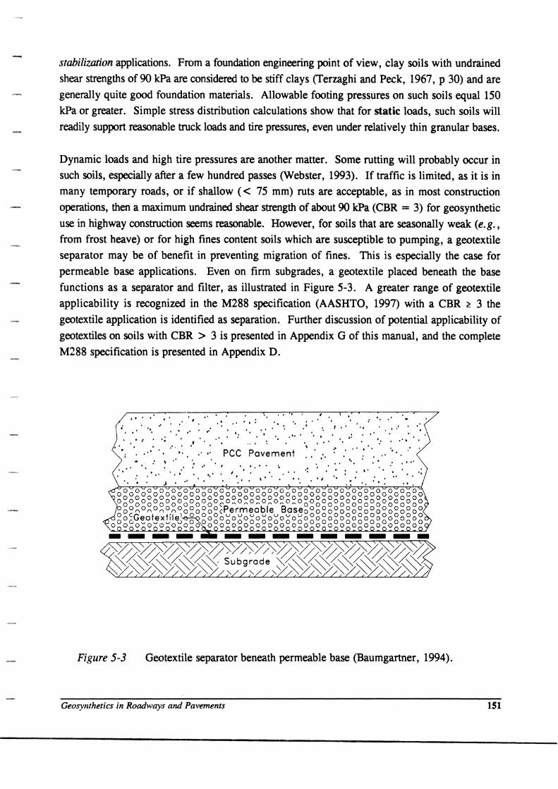
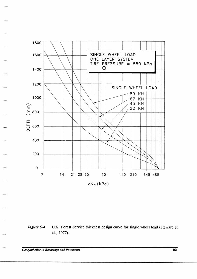
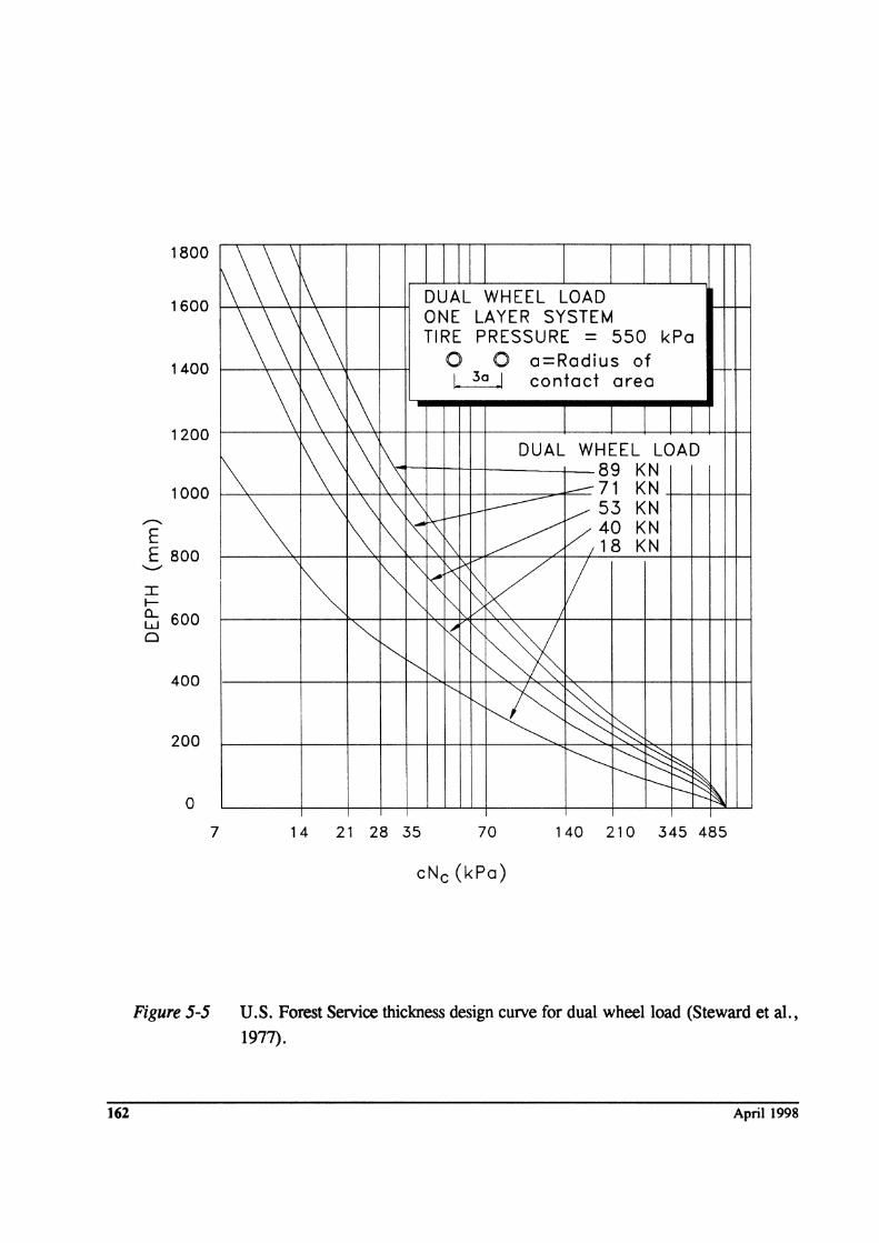
STEP 7. Determine required aggregate thickness.
Determine the required aggregate thickness from the USFS design charts (Figures 5-4, 5-5,
and 5-6) for each maximum loading. Enter the curve with appropriate bearing capacity factors
(Nc) multiplied by the design subgrade undrained shear strength (c) to evaluate each required
stress level (cNc)'
STEP 8. Select design thickness.
160
Select the design thickness based on the design requirements. The design thickness should be
given to the next higher 25 mm.
April 1998
1800
1600
1400
1200
1000
--.. E E 800
I I-
~ 600 o
400
200
o 7
\ \ \ i\ SINGLE WHEEL LOAD \\ \\ ONE LAYER SYSTEM TIRE PRESSURE = 550 kPa
0
\ \ 1\ 1\ \ 1\ \ SINGLE WHEEL LOAD
~ 89 KN \. 1\ -----Y 67 KN \ 1\ \ 1\ --f--
I"'" ..-
~ 45 KN
"" \ 0 22 KN '\ '" ~ 1'\ "" -<x VI / ~ ~ "" "" ~
"" ",<
~ '" ~ "'" "-
~ ~ ~ ~ ~ ~ ~
......... ............... ~ ~ I'---- ~ .............
~ ~ 14 21 28 35 70 140 210 345 485
cNc (kPa)
Figure 5-4 U. S. Forest Service thickness design curve for single wheel load (Steward et
at., 1977).
Geosynlhelics in Roadways and Pavements 161
1800
1600
1400
1200
1000
,..-...
E E 800
I I-
f:j 600 o
400
200
o 7
\\ \\ 1\ DUAL WHEEL LOAD
\ \\ 1\\ ONE LAYER SYSTEM TIRE PRESSURE = 550 kPa
0 0 a=Radius of r--r- r-
\ ~\ l\ I 30 I contact area
\\ ~ 1\ DUAL WHEEL LOAD
1\ \ 89 KN \ -71 KN
\ \ \ \ \ I------ /53 KN K
,...-
1\ ~ ~ ~ /.40 KN '\. 1\ /18 KN
~ ~ "'" ~
XV
K'I / '<: ,,1\
"" "" [> ~ r< ~ ~ ~ "'-
~ '" '-... i"'--
...............
~ ~ ~ ~ ~ ~ ~ r-------- ~ -----I-.........: ~
14 21 28 35 70 140 210 345 485
cNc(kPa)
Figure 5-5 U.S. Forest Service thickness design curve for dual wheel load (Steward et aI.,
1977).
162 April 1998

1800
1600
1400
1200
1000
--. E E 800
I f-
EJ 600 o
400
200
o 7
\ \ \\ TANDEM WHEEL LOAD ONE LAYER SYSTEM
\ \ \ TIRE PRESSURE = 550 kPa
1\ E[O ° a=Radius of ~ 0 0 contact area
\
1\\ 1\ I 30 I
1\ \ '\ I TANDEM WHEEL LOAD
\ \ \ \ rs 1-195 KN (912 KN GVW Log Truck)
1\167 KN (712 KN GVW Log Truck) \ 1\ r\
\ \ \ 1\ \ \ \\ 1\ 1\ 11\ 1\ '\
\ ~ 1\ ~ ~ !\ ~ ~ !\
~ '" ~ ~
~ '" """ t'-, '~K
107 KN (480 KN GVW Log Truck) ~ ~ ~ I I I I I I I I C> ~ ~ ~ 78 KN (Legal Log or 7.6 m3 Dump) / --......... ~ ~ ~ I I I I I I I I 36 KN /
r---. --- ~ I I I I I
14 21 28 35 70 140 210 345 485
cNc (kPa)
Figure 5-6 u.s. Forest Service thickness design curve for tandem wheelload (Steward et
at., 1977).
Geosynthetics in Roadways and Pavements 163

STEP 9. Check geotexti1e drainage and filtration characteristics.
Check the geotextHe drainage and filtration requirements. Use the gradation and permeability
of the subgrade, the water table conditions, and the retention and permeability criteria given
in Chapter 2. In high water table conditions with heavy traffic, filtration criteria may also be
required. From Chapter 2, that criteria is:
AOS :s: D85 (Wovens)
AOS :s: 1.8 D85 (Nonwovens)
~eotextile ~ k.oil
liT ~ 0.1 sec-I
(Eq. 2-3)
(Eq. 2-4)
(Eq.2-7a)
(Eq.2-8c)
STEP 10. Determine geotextile survivability requirements.
Check the geotextile survivability strength requirements as discussed in Section 5.5.
STEP 11. Specify geotextile property requirements.
Specify geotextiles that meet or exceed these survivability criteria.
STEP 12. Specify construction requirements.
Follow the construction recommendations in Section 5.12
5.7 TEMPORARY ROAD DESIGN EXAMPLE
DEFINITION OF DESIGN EXAMPLE
• Project Description: A haul road over wet, soft soils is required for a highway construction project.
• Type of Structure: temporary unpaved road
• Type of Application: geotextile separator
• Alternatives:
GIVEN DATA
• subgrade
• traffic
164
i) excavate unsuitable material and increased aggregate thickness ii) geotextile separator between aggregate and subgrade iii) use an estimated depth of aggregate and maintain as required
cohesive subgrade soils high water table average undrained shear strength about 30 kPa or CBR = 1
approximately 5000 passes 90 kN single axle truck 550 kPa tire pressure
April 1998

• ruts maximum of 50 to 100 mm
REOUIRED
Design the roadway section.
Consider: 1) design without a geotextile; and 2) alternate with geotextile.
DEFINE
A. Geotextile function(s):
B. Geotextile properties required:
C. Geotextile specification:
SOLUTION
A. Geotextile function(s): Primary separation Secondary filtration, drainage, reinforcement
B. Geotextile properties required: survivability apparent opening size (AOS)
DESIGN Design roadway with and without geotextile inclusion. Compare options.
STEP 1. DETERMINE SOIL SUBGRADE STRENGTH
given CBR'" 1
STEP 2. DETERMINE SUBGRADE STRENGTH AT SEVERAL LOCATIONS
Assume that CBR '" 1 is taken from area(s) where the subgrade appears to be the weakest.
STEP 3. DETERMINE WHEEL LOADING
given 90 kN single-axle truck, with 550 kPa tire pressure therefore, 45 kN single wheel load
STEP 4. ESTIMATE AMOUNT OF TRAFFIC
given 5,000 passes
STEP 5. ESTABLISH TOLERABLE RUTTING
given 150 to 200 mm
Geosynthetics in Roadways and Pavements 165
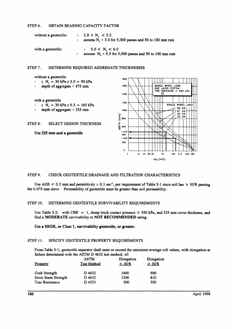
STEP 6. OBTAIN BEARING CAPACITY FACTOR
without a geotextile: 2.8 < N. < 3.3 assume N. '" 3.0 for 5,000 passes and 50 to 100 mm ruts
with a geotextile: 5.0 < N. < 6.0 assume N. '" 5.5 for 5 ,000 passes and 50 to 100 mm ruts
STEP 7. DETERMINE REQUIRED AGGREGATE THICKNESSES
without a geotextile c N. = 30kPax3.0 = 90kPa depth of aggregate'" 475 mm
with a geotextile
STEP 8.
c N. = 30 kPax 5.5 = 165 kPa depth of aggregate '" 325 mm
SELECT DESIGN THICKNESS
Use 325 mm and a geotextile
1800
1600
1400
1200
1000
E !. 800
:I: .... e; 600 Q
~475
400
~325
200
o
\ \ \ \ \
\ \ 1\ \
\ '\.
'"
II I SINGLE WHEEL LOAD ONE LAYER SYSTEM TIRE PRESSURE = 550 kPo
0
\ \ 1\ SINGLE WHEEL LOAD
....--I-- 89 KN
\ 1'\[\ V 67 KN
/ V.45 KN /22 KN
"" ~ ~/ r'- ~ ~
rz :::-.:. ~ "-.. ~ ......... r---R~
14 21 28 J5 70 140 210 J45 485
eNe (kPo)
STEP 9. CHECK GEOTEXTILE DRAINAGE AND FILTRATION CHARACTERISTICS
Use AOS < 0.3 mm and permittivity ~ 0.1 sec·', per requirement of Table 5-1 since soil has > 50% passing the 0.075 mm sieve. Permeability of geotextile must be greater than soil permeability.
STEP 10. DETERMINE GEOTEXTILE SURVIVABILITY REQUIREMENTS
Use Table 5-2: with CBR = 1, dump truck contact pressure> 550 kPa, and 325 mm cover thickness, and find a MODERATE survivability to NOT RECOMMENDED rating.
Use a IDGH, or Class 1, survivability geotextile, or greater.
STEP 11. SPECIFY GEOTEXTILE PROPERTY REQUIREMENTS
166
From Table 5-1; geotextile separator shall meet or exceed the minimum average roll values, with elongation at failure determined with the ASTM D 4632 test method, of:
Property
Grab Strength Sewn Seam Strength Tear Resistance
ASTM Elongation Test Method < 50 %
D4632 D4632 D4533
1400 1200
500
Elongation > 50%
900 810 350
April 1998
Puncture Burst Ultraviolet Stability
D 4833 D 3786 D4355
500 350 3500 1700
50 % strength retained after 500 hours
The geotextile shall have an AOS < 0.3 rom, ljr ~ 0.1 sec-I, and the permeability shall be __ .
STEP 12. SPECIFY CONSTRUCTION REQUIREHENTS
See Section 5.12
5.8 DESIGN GUIDELINES FOR PERMANENT ROADWAYS
The recommended design method for using geotextiles in permanent pavements is that developed
by Christopher and Holtz (1985; 1991). It is based on the following concepts:
1. Standard methods are used to design the overall pavement system (i.e., AASHTO, CBR,
R-value, resilent modulus, etc.).
2. The geotextile is assumed to provide no structural support, therefore, no reduction is allowed in aggregate thickness required for structural support.
3. Aggregate savings is achieved through a reduction in the stabilization aggregate required
for construction but not used for structural support.
4. The recommended method is used to design the first construction lift, which is called the
stabilizer lift since it sufficiently stabilizes the subgrade to allow access by normal
construction equipment.
5. Once the stabilizer lift is completed, construction proceeds using standard methods.
The design method assumes that the stabilizer lift is an unpaved road which will be exposed to
relatively few vehicle passes (i. e., construction equipment only) and which can tolerate 50 to 75
mm of rutting under the equipment loads. The design consists of the following steps:
STEP 1. Assess need for geotextile.
Estimate the need for a geotextile based on the subgrade strength and by past performance in
similar types of soils.
STEP 2. Design pavement without geotextile.
Design the roadway for structural support using normal pavement design methods; provide no
allowance for the geotextile.
Geosynthetics in Roadways and Pavements 167

STEP 3. Determine need for additional aggregate.
See Figure 5-7 to determine if additional aggregate above that required for structural support
is needed due to susceptibility of soils to pumping and base course intrusion. If so, reduce that
aggregate thickness and include a geotextile at the base/subgrade interface. Note that a
thickness reduction of approximately 50% is normally cost effective.
1.00 1 CDR
2.00
Figure 5-7 Aggregate loss to weak subgrades (FHW A, 1989; in Christopher and
Holtz, 1991).
STEP 4. Determine aggregate depth required to support construction equipment.
Determine the additional aggregate required for stabilization of the subgrade during
construction activities. Use a 50 to 75 mm rutting criteria for construction equipment, and
refer to the procedures outlined in Section 5.6.
STEP 5. Compare thicknesses.
Compare the aggregate-geotextile system thicknesses determined in Steps 3 and 4. Use the
system with the greater thick.'1ess.
STEP 6. Check geotextile filtration.
168
Check the geotextile filtration characteristics using the gradation and permeability of the
subgrade, the water table conditions, and the retention and permeability criteria. From
Chapter 2, that criteria is:
April 1998

AOS ~ D85 (Wovens)
AOS ~ 1. 8 D85 (Nonwovens)
~eotextile ~ ~oil \jI ~ 0.1 sec-I
(Eq. 2-3)
(Eq. 2-4)
(Eq. 2-7a)
(Eq. 2-8c)
STEP 7. Determine geotextile survivability requirements.
Check the geotextile strength requirements for survivability as discussed in Section 5.5.
STEP 8. Specify geotextiles that meet or exceed those survivability criteria.
STEP 9. Follow the construction recommendations in Section 5.12.
Design methods for improving the structural capacity of permanent roads using geotextiles (e.g.,
Hamilton and Pearce, 1981) and geogrids (e.g., Haas, 1986; Haas, et. aI., 1988; Barksdale, et
aI., 1989; Webster, 1993) have been proposed and may also be used. If a geogrid is used, either
the base material should be sufficiently well graded to provide subgrade filtration and prevent soil
intrusion, or for more open bases, a geotextile filter should be used with the geogrid.
5.9 PERMANENT ROAD DESIGN EXAMPLE (Christopher and Holtz, 1991)
DEFINITION OF DESIGN EXAMPLE
• Project Description: New public street and service drive for a suburban Washington, D.C., townhouse development. State of Virginia DOT regulations apply.
• Type of Structure: Category IV street (permanent road)
• Type of Application: geotextile separator
• Alternatives:
GIVEN DATA
• subgrade
i) excavate unsuitable material and increase subgrade aggregate thickness; or ii) geotextile separator between aggregate and subgrade
surficial soils: micaceous silts (CBR '" 2) local areas of very poor soils (CBR '" 0.5) low-lying topography poor drainage other nearby streets and roads require frequent maintenance
Geosynthetics in Roadways and Pavements 169
• traffic maximum 300 vehicles per day 96 % passenger, 5 % single-axle, 1 multiaxle equivalent daily 90 kN single-axle load (EAL) applications = 10
REOUIRED
Design the pavement section.
Consider: 1) standard AASHTO design; and 2) alternate with geotextile
DEFINE
A. Geotextile function(s):
B. Geotextile properties required:
C. Geotextile specification:
SOLUTION
A. Geotextile function(s): Primary separation Secondary filtration
B. Geotextile properties required: survivability apparent opening size (AOS) permeability
DESIGN Design pavement with and without geotextile inclusion. Compare options.
STEP 1. ESTIMATE NEED FOR GEOTEXTILE
Ideal conditions for considering a geotextile; e.g., low CBR, saturated subgrade, and poor performance history with conventional design.
STEP 2. DESIGN WITHOUT GEOTEXTILE
170
The structural design for the pavement section is based on the AASHTO Guide for Design of Pavement Structures (1977) using an equivalent design structural number for the anticipated loading and soil support conditions. (NOTES: i) AASHTO design uses English units; and ii) this case history used the AASHTO guide, 1977, which was current at time of design.)
traffic - as given
Determine structural number, SN: from AASHTO design charts and with 20 years, CBR = 2, EAL = 10, and Regional Factor = 2 SN is equal to 2.9
April 1998
Compute pavement thickness for structural support on a stable subgrade (i.e., no fines pumped into aggregate subbase and no aggregate loss down into the subgrade):
Assume 2.5 inches asphaltic concrete surface and S inches aggregate base course
surface + base + subbase
SN a. D. + ~D2 + ~D)
2.9 0.4 x 2.5" + 0.14xS" + 0.13 x D)
Therefore, D) = 6 inches required for subbase.
Structural design: 2.5" asphaltic concrete S" aggregate base 6" aggregate subbase
STEP 3. ADDITIONAL AGGREGATE FOR PUMPING AND INTRUSION
By local experience in this area, and for subgrades of CBR s: 2, an additional S inches of aggregate subbase is required (stabilization aggregate).
For the geotextile separator alternate, this entire stabilization layer could be eliminated. However, some very poor soils are anticipated, and some conservatism can be applied. Therefore, reduce subbase aggregate thickness to 4 inches (100 mm) with use of a geotextile separator.
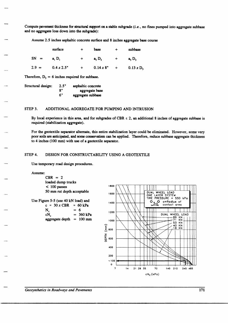
STEP 4. DESIGN FOR CONSTRUCT ABILITY USING A GEOTEXTILE
Use temporary road design procedures.
Assume: CBR = 2 loaded dump trucks < 100 passes 50 mm rut depth acceptable
Use Figure 5-5 (use 40 kN load) and c '" 30 x CBR :::J 60 kPa N. 6 cN. 360 kPa aggregate depth 100 mm
Geosynthetics in Roadways and Pavements
1800
1600
1(00
1200
1000
E .5. 800
:J: I-
~ 600 0
.00
200
-100
0
7
1\\ \\\ I I DUAL WHEEL LOAD
\\' \\ ONE LAYER SYSTEM TIRE PRESSURE = 550 kPa
o 0 o=Rodius of
i ~\ ,\ I 30 I contad area
~\ ,\1\ DUAL WHEEL LOAD
~ 89 KN ~7' KN
-~ \ \ \ ~ ~ 53 KN
~ 1\ "'\:" ~ V,40 KN 18 KN
i~ I"" ",<, ~ / I" '-.....
f'--r---r< ~ ~ ~ ~
0 ~ §;~ It- f\
U 21 28 35 70 1 (0 210 345 (85
cNc (kPo)
171
STEP 5. COMPARE THE THICKNESSES DETERMINED IN STEPS 3 AND 4
The two thicknesses are equal; therefore, use 100 mm of stabilization aggregate with a geotextile separator. Note that the minimum thickness of aggregate for a construction haul road is 100 mm, though the contractor will likely use a greater thickness.
STEP 6. CHECK GEOTEXTILE FILTRATION CHARACTERISTICS
Use AOS < 0.3 mm per Table 5-1 because> 50% passing the 0.015 mm sie·"e.
Permeability of geotextile must be greater than soil permeability per Table 5-1. Estimate soil permeability and determine geotextile requirement.
STEP 1. DETERMINE GEOTEXTILE SURVIVABILITY REQUIREMENTS
Use Table 5-2, with CBR = 2, dump truck contact pressure> 350 kPa, and 150 mm cover thickness (note that 100 mm cover is limited to existing road bases, therefore 150 mm minimum compacted lift thickness is recommended), and determine that a geotextile with a mGH, or Class 1, survivability rating is required.
STEP 8. SPECIFY GEOTEXTILE PROPERTY REQUIREMENTS
From Table 5-1; geotextile separator shall meet or exceed the minimum average roll values, with elongation at failure determined with the ASTM D 4632 test method, of:
ASTM Elongation Elongation Property Test Method < 50% > 50%
Grab Strength D4632 1400 900 Sewn Seam Strength D 4632 1200 810 Tear Resistance D 4533 500 350 Puncture D4833 500 350 Burst D 3186 3500 1100 Ultraviolet Stability 04355 50% strength retained after 500 hours
The geotextile shall have an AOS < 0.3 mm, lJI ~ 0.1 sec"I, and the permeability shall be __ .
STEP 9. SPECIFY CONSTRUCTION REQUIREMENTS
See Section 5.12
5.10 COST CONSIDERATIONS
Estimation of construction costs and benefit-cost ratios for geosynthetic-stabilized road
construction is straight-forward and basically the same as that required for alternative pavement
designs. Primary factors include the following:
1. cost of the geosynthetic;
2. cost of constructing the conventional design versus a geosynthetic design (i.e., stabilization
172 April 1998
requirements for conventional design versus geosynthetic design), including
a) stabilization aggregate requirements,
b) excavation and replacement requirements,
c) operational and technical feasibility, and
d) construction equipment and time requirements;
3. cost of conventional maintenance during pavement service life versus improved service
anticipated by using geosynthetic (estimated through pavement management programs);
and
4. regional experience.
Annual cost formulas, such as the Baldock method (Illinois DOT, 1982), can be applied with an
appropriate present worth factor to obtain the present worth of future expenditures.
Cost tradeoffs should also be evaluated for different construction and geosynthetic combinations.
This should include subgrade preparation and equipment control versus geosynthetic survivability.
In general, higher-cost geosynthetics with a higher survivability on the existing subgrade will be
less expensive than the additional subgrade preparation necessary to use lower-survivability
geosynthetics.
Research is ongoing to quantify the cost-benefit life cycle ratio of using geosynthetics in
permanent roadway systems. In any case, the cost of a geosynthetic is generally $1.25/m2 while
the cost of the pavement section is generally $25/m2. The life extension of the roadway section will more than make up for the cost of the geosynthetic. The ability of a geosynthetic to prevent premature failure provides an extremely low-cost performance insurance.
5.11 SPECIFICATIONS
5.11-1 Geotextile for Separation and Stabilization Applications Specifications should generally follow the guidelines in Section 1.6. The main considerations
include the minimum geotextile requirements for design and those obtained from the survivability,
retention, and filtration requirements in (Sections 5.5 and 5.8), as well as the construction
requirements covered in Section 5.12. As with other applications, it is very important that an
engineer's representative be on site during placement to observe that the correct geotextile has
been delivered, that the specified construction sequence is being followed in detail, and that no
damage to the geotextile is occurring. The following example specification is a combination of
the AASHTO M288 (1997) geotextile material specification and its accompanying
construction/installation guidelines.
Geosynthetics in Roadways and Pavements 173
SPECIFICATION FOR GEOTEXTILES USED IN
SEPARATION AND STABILIZATION APPLICATIONS (after AASHTO M288, 1997)
1. SCOPE
1.1 Description. This specification is applicable to the use of a geotextile to prevent mixing of a subgrade soil and
an aggregate cover material (i.e., separation application); and to the use of a geotextile in wet, saturated
conditions to provide the coincident functions of separation and filtration (i. e., stabilization application). In some
stabilization applications, the geotextile can also provide the function of reinforcement.
1.2 Separation. The separation application is appropriate for pavement structures constructed over soils with a
California Bearing Ratio greater than or equal to three (CBR 2 3) (shear strength greater than .pproximately 90
kPa). It is appropriate for unsaturated subgrade soils. The primary function of a geotextile in this application
is separation.
1.3 Stabilization. The stabilization application is appropriate for subgrade soils which are saturated due to a high
groundwater table or due to prolonged periods of wet weather. Stabilization is applicable to pavement structures constructed over soils with a CBR between one and three (1 < CBR < 3) (shear strength between approximately
30 kPa and 90 kPa). This specification is not appropriate for embankment reinforcement where stress conditions
may cause global subgrade foundation or stability failure. Reinforcement of the pavement section is a site-specific
design issue.
2. REFERENCED DOCUMENTS
2.1 AASHTO Standards
T88 Particle Size Analysis of Soils
T90 Determining the Plastic Limit and Plasticity Index of Soils
T99 The Moisture-Density Relationships of Soils Using a 2.5 kg Rammer and a 305 mm Drop
2.2 AS1M Standards
174
D 123 Standard Terminology Relating to Textiles
D 276 Test Methods for Identification of Fibers in Textiles
D 3786 Test Method for Hydraulic Burst Strength of Knitted Goods and Nonwoven Fabrics, Diaphragm Bursting Strength Tester Method
D 4354 Practice for Sampling of Geosynthetics for Testing
D 4355 Test Method for Deterioration of Geotextiles from Exposure to Ultraviolet Light and Water (Xenon Arc
Type Apparatus) D 4439 Terminology for Geosynthetics
D 4491 Test Methods for Water Permeability of Geotextiles by Permittivity
D 4632 Test Method for Grab Breaking Load and Elongation of Geotextiles
D 4751 Test Method for Determining Apparent Opening Size of a Geotextile D 4759 Practice for Determining the Specification Conformance of Geosynthetics
D 4833 Test Method for Index Puncture Resistance of Geotextiles, Geomembranes and Related Products
D 4873 Guide for Identification, Storage, and Handling of Geotextiles
April 1998

D 5141 Test Method to Determine Filtering Efficiency and Flow Rate for Silt Fence Applications Using Site
Specific Soil
3. PHYSICAL AND CHEMICAL REQUIREMENTS
3.1 Fibers used in the manufacture of geotextiles and the threads used in joining geotextiles by sewing, shall consist
of long chain synthetic polymers, composed of at least 95 % by weight polyolefins or polyesters. They shall be
formed into a stable network such that the filaments or yams retain their dimensional stability relative to each
other, including selvages.
3.2 Geotextile Requirements. The geotextile shall meet the requirements of following Table. Woven slit film
geotextiles (i.e., geotextiles made from yams of a flat, tape-like character) will not be allowed. All numeric
values in the following table, except AOS, represent minimum average roll values (MARV) in the weakest
principal direction (i. e., average test results of any roll in a lot sampled for conformance or quality assurance
testing shall meet or exceed the minimum values). Values for AOS represent maximum average roll values.
4. CERTIFICATION
4.1 The Contractor shall provide to the Engineer a certificate stating the name of the manufacturer, product name,
style number, chemical composition of the filaments or yams and other pertinent information to fully describe
the geotextile.
4.2 The Manufacturer is responsible for establishing and maintaining a quality control program to assure compliance
with the requirements of the specification. Documentation describing the quality control program shall be made
available upon request.
4.3 The Manufacturer's certificate shall state that the furnished geotextile meets MARV requirements of the
specification as evaluated under the Manufacturer's quality control program. The certificate shall be attested to
be a person having legal authority to bind the Manufacturer.
4.4 Either mislabeling or misrepresentation of materials shall be reason to reject those geotextile products.
s. SAMPLING, TESTING, AND ACCEPTANCE
5.1 Geotextiles shall be subject to sampling and testing to verify conformance with this specification. Sampling for
testing shall be in accordance with ASTM D 4354. Acceptance shall be based on testing of either conformance
samples obtained using Procedure A of ASTM D 4354, or based on manufacturer's certifications and testing of
quality assurance samples obtained using Procedure B of ASTM D 4354. A lot size for conformance or quality
assurance sampling shall be considered to be the shipment quantity of the given product or a truckload of the
given product, whichever is smaller.
5.2 Testing shall be performed in accordance with the methods referenced in this specification for the indicated
application. The number of specimens to test per sample is specified by each test method. Geotextile product
acceptance shall be based on ASTM D 4759. Product acceptance is determined by comparing the average test
results of all specimens within a given sample to the specification MARV. Refer to ASTM D 4759 for more
details regarding geotextile acceptance procedures.
Geosynthetics in Roadways and Pavements 175

Geotextile Requirements for Separation and Stabilization Applications
Separation Application Stabilization Application Class 2(1) Class 1(2)
Property ASTM Test Units Geotextile Geotextile Geotextile Geotextile
Method Elongation Elongation Elongation Elongation < 50%(3) 2.. 50%(3) < 50%(3) 2.. 50%(3)
Grab Strength D4632 N 1100 700 1400 900
Sewn Seam Strength(4) D 4632 N 990 630 1200 810
Tear Strength D 4533 N 400(3) 250 500 350
Puncture Strength D 4833 N 400 250 500 350
Burst Strength D 3786 kPa 2700 1300 3500 1700
Permittivity D 4491 sec'! 0.02(3) 0.05(3)
Apparent Opening Size D4751 mm 0.60 max. 0.43 max.
Ultraviolet Stability D 4355 % 50 % after 500 hours of exposure
(Retained Strength)
NOTES:
(1) Default geotextile selection. The Engineer may specify a Class 3 geotextile [Appendix D] based on one or
more of the following:
a) The Engineer has found Class 3 geotextiles to have sufficient survivability based on field experience.
b) The Engineer has found Class 3 geotextiles to have sufficient survivability based on laboratory testing
and visual inspection of a geotextile sample removed from a field test section constructed under
anticipated field conditions.
c) Aggregate cover thickness of the first lift over the geotextile exceeds 300 mm and aggregate diameter
is less than 50 mm.
d) Aggregate cover thickness of the first lift over the geotextile exceeds 150 mm, aggregate diameter is
less than 30 mm, and construction equipment contact pressure is less than 550 kPa.
(2) Default geotextile selection. The Engineer may specify a Class 2 or 3 geotextile [Appendix D] based on
one or more of the following:
a) The Engineer has found the class of geotextile to have sufficient survivability based on field
experience.
b) The Engineer has found the class of geotextile to have sufficient survivability based on laboratory
testing and visual inspection of a geotextile sample removed form a field test section constructed under
anticipated field conditions.
(3) As measured in accordance with ASTM D 4632.
(4) When sewn seams are required.
(5) Default value. Permittivity of the geotextile should be greater than that of the soil CP, > 11'.). The
Engineer may also require the permeability of the geotextile to be greater than that of the soil (k, > k.).
6. SHIPMENT AND STORAGE
6.1 Geotextile labeling, shipment, and storage shaH foHow ASTM D 4873. Product labels shaH clearly show the
manufacturer or supplier name, style number, and roH number. Each shipping document shaH include a notation
176 April 1998
certifying that the material is in accordance with the manufacturer's certificate.
6.2 Each geotextile roll shall be wrapped with a material that will protect the geotextile from damage due to shipment,
water, sunlight, and contaminants. The protective wrapping shall be maintained during periods of shipment and
storage.
6.3 During storage, geotextile rolls shall be elevated off the ground and adequately covered to protect them from the
following: site construction damage, precipitation, extended ultraviolet radiation including sunlight, chemicals
that are strong acids or strong bases, flames including welding sparks, temperatures in excess of 71 °C (l60°F),
and any other environmental condition that may damage the physical property values of the geotextile.
7. CONSTRUCTION
7.1 General. Atmospheric exposure of geotextiles to the elements following lay down shall be a maximum of 14 days
to minimize damage potential.
7.2 Seaming.
a. If a sewn seam is to be used for the seaming of the geotextile, the thread used shall consist of high strength
polypropylene, or polyester. Nylon thread shall not be used. For erosion control applications, the thread shall
also be resistant to ultraviolet radiation. The thread shall be of contrasting color to that of the geotextile itself.
b. For seams which are sewn in the field, the Contractor shall provide at least a 2 m length of sewn seam for
sampling by the Engineer before the geotextile is installed. For seams which are sewn in the factory, the
Engineer shall obtain samples of the factory seams at random from any roll of geotextile which is to be used on
the project.
b.l For seams that are field sewn, the seams sewn for sampling shall be sewn using the same equipment and
procedures as will be used for the production of seams. If seams are to be sewn in both the machine and
cross machine directions, samples of seams from both directions shall be provided.
b.2 The seam assembly description shall be submitted by the Contractor along with the sample of the seam. The
description shall include the seam type, stitch type, sewing thread, and stitch density.
7.3 Site Preparation. The installation site shall be prepared by clearing, grubbing, and excavation or filling the area
to the design grade. This includes removal of top soil and vegetation.
NOTE: Soft spots and unsuitable areas will be identified during site preparation or subsequent proof
rolling. These areas shall be excavated and backfilled with select material and compacted using
normal procedures.
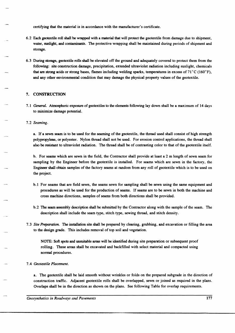
7.4 Geotextile Placement.
a. The geotextile shall be laid smooth without wrinkles or folds on the prepared subgrade in the direction of
construction traffic. Adjacent geotextile rolls shall be overlapped, sewn or joined as required in the plans.
Overlaps shall be in the direction as shown on the plans. See following Table for overlap requirements.
Geosynthetics in Roadways and Pavements 177
Overlap Requirements
SOIL CBR MINIMUM OVERLAP
Greater than 3 300 - 450 mm
1 - 3 0.6 - 1 m
0.5 - 1 1 m or sewn
Less than 0.5 Sewn
All Roll Ends 1 m or sewn
a.l On curves the geotextile may be folded or cut to conform to the curves. The fold or overlap shall be in the
direction of construction and held in place by pins, staples, or piles of fill or rock.
a.2 Prior to covering, the geotextile shall be inspected by a certified inspector of the Engineer to ensure that the
geotextile has not been damaged (i. e., holes, tears, rips) during installation. Damaged geotextiles, as
identified by the Engineer, shall be repaired immediately. Cover the damaged area with a geotextile patch
which extends an amount equal to the required overlap beyond the damaged area.
b. The subbase shall be placed by end dumping onto the geotextile from the edge of the geotextile, or over
previously placed subbase aggregate. Construction vehicles shall not be allowed directly on the geotextile. The
subbase shall be placed such that at least the minimum specified lift thickness shall be between the geotextile and
equipment tires or tracks at all times. Turning of vehicles shall not be permitted on the first lift above the
geotextile.
NOTE: On subgrades having a CBR values of less than 1, the subbase aggregate should be spread
in its full thickness as soon as possible after dumping to minimize the potential of localized subgrade
failure due to overloading of the sub grade.
b.l Any ruts occurring during construction shall be filled with additional subbase material, and compacted to
the specified density.
b.2 If placement of the backfill material causes damage to the geotextile, the damaged area shall be repaired as
previously described in section 7.4.a.2. The placement procedures shall then be modified to eliminate further
damage from taking place. (i.e., increased initial lift thickness, decrease equipment loads, etc.)
NOTE: In stabilization applications, the use of vibratory compaction equipment is not
recommended with the initial lift of subbase material, as it may cause damage to the geotextile.
8. METHOD OF MEASUREMENT
178
8.1 The geotextile shall be measured by the number of square meters computed from the payment lines shown
on the plans or from payment lines established in writing by the Engineer. This excludes seam overlaps, but shall
include geotextiles used in crest and toe of slope treatments.
April 1998
8.2 Slope preparation, excavation and backfill, bedding, and cover material are separate pay items.
9. BASIS OF PAYMENT
9.1 The accepted quantities of geotextile shall be paid for per square meter in place.
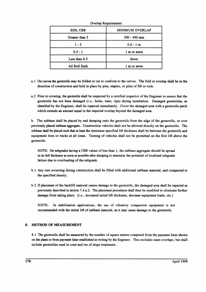
9.2 Payment will be made under:
Pay Item
Separation Geotextile
Stabilization Geotextile
5.11-2 Geogrid Reinforcement
Pay Unit
Square Meter
Square Meter
An AASHTO, or other standard setting organization, geogrid specification for reinforcement of
pavement structures is, presently, not available. Nor was a widely accepted, typical state agency
specification for geogrid reinforcement located for inclusion in this manual (though several
agency's do have a geogrid reinforcement specification). A typical, generic type material
specification for geogrid reinforcement for pavements will be difficult to develop because of: the
proprietary naturt; (Le., current product patents) of biaxial geogrids; the absence of generic design
procedure; a lack of understanding of the mechanistic benefits of geogrid reinforcement; lack of a clear definition of the function(s) of the geogrid in pavement reinforcement application; lack of
side-by-side product performance testing; lack of performance documentation; and inability to
measure contribution of geogrid reinforcement to pavement structure with non-destructive testing
methods.
Agencies which are using geogrids in pavements have typically initiated use after the following
considerations:
1. Define purpose and applicability geogrid reinforcement. For example, geogrid reinforcement
may be used to minimize over excavation over soft subgrades, to reduce or minimize
aggregate base course thickness, to extend pavement life (Le., analysis period), or a
combination of these.
2. Define function(s) of geosynthetic, and assess applicability of geogrids.
3. Construct and monitor a demonstration project to examine performance of candidate geogrid
reinforcement(s) versus the agency's conventional construction technique.
4. With satisfactory performance, write a material specification which either lists prequalified
products or lists key property requirements.
5. Monitoring of additional projects to confirm anticipated performance, and construction of
additional demonstration projects to confirm performance of new products, as needed.
Geosynthetics in Roadways and Pavements 179

Thus, a geogrid pavement reinforcement specification may list prequalified products or key
property requirements. Key property requirements may include definition of some, or all, of the
following properties: aperture size; percent open area; tensile modulus (initial, or 2 % or 5 %
secant); rib junction strength; rib junction efficiency; rib thickness; flexural rigidity; and secant
aperture stability. See Webster (1993) for a description of the aperture stability test procedure,
and applicability of results to their test program.
A geogrid reinforcement specification should allow use of other geogrid products that either: (i)
meet the physical properties defined by the key property requirements; or (ii) by demonstrating
performance equivalency through full-scale laboratory testing, in-ground testing of pavements,
and prior projects.
5.12 INSTALLATION PROCEDURES
5.12-1 Roll Placement Successful use of geotextiles in pavements requires proper installation, and Figure 5-8 shows the
proper sequence of construction. Even though the installation techniques appear fairly simple,
most geotextile problems in roadways occur as the result of improper construction techniques.
If the geotextile is ripped or punctured during construction activities, it will not likely perform as
desired. If the geotextile is placed with a lot of wrinkles or folds, it will not be in tension, and,
therefore, cannot provide a reinforcing effect. Other problems occur due to insufficient cover
over the geotextile, rutting of the subgrade prior to placing the geotextile, and thin lifts that exceed
the bearing capacity of the soil. The following step-by-step procedures should be followed, along
with careful observations of all construction activities.
1. The site should be cleared, grubbed, and excavated to design grade, stripping all topsoil,
soft soils, or any other unsuitable materials (Figure 5-8a). If moderate site conditions
exist, i. e., eBR greater than 1, lightweight proofrolling operations should be considered
to help locate unsuitable materials. Isolated pockets where additional excavation is
required should be backfilled to promote positive drainage. Optionally, geotextile
wrapped trench drains could be used to drain isolated areas.
2. During stripping operations, care should be taken not to excessively disturb the subgrade.
180
This may require the use of lightweight dozers or grade-alls for low-strength, saturated,
noncohesive and low-cohesive soils. For extremely soft ground, such as peat bog areas,
do not excavate surface materials so you may take advantage of the root mat strength, if
it exists. In this case, all vegetation should be cut at the ground surface. Sawdust or sand
can be placed over stumps or roots that extend above the ground surface to cushion the
April 1998

a. Prepare the ground by removing stumps. boulders. etc.: fill in low spots
PREPARE THE GROUND
c. Back dump aggregate onto previously placed aggregate. Do not drive on the geotextile. Maintain 150 mm to 300 mm cover between truck tires and Geotextile.
BACK DUMP AGGREGATE
b. Unroll the geotextile directly over the ground to be stabilized. If more than one roll is required. overlap rolls. Inspect geotextile.
UNROLL THE GEOTEXTILE
d. Spread the aggregate over the geotextile to the design thickness.
SPREAD THE AGGREGATE
e. Compact the aggregate using dozer tracks or smooth drum vibratory roller.
COMPACT THE AGGREGATE
Figure 5-8 Construction sequence using geotextiles.
Geosynthetics in Roadways and Pavements 181
geotextile. Remember, the subgrade preparation must correspond to the survivability
properties of the geotextile.
3. Once the subgrade along a particular segment of the road alignment has been prepared, the
geotextile should be rolled in line with the placement of the new roadway aggregate
(Figure 5-8b). Field operations can be expedited if the geotextile is pre-sewn to design
widths in the factory so it can be unrolled in one continuous sheet. The geotextile should
not be dragged across the sub grade. The entire roll should be placed and rolled out as
smoothly as possible. Wrinkles and folds in the fabric should be removed by stretching
and staking as required.
4. Parallel rolls of geotextiles should be overlapped, sewn, or joined as required. (Specific
requirements are given in Sections 5.12-2 and 5.12-3.)
5. For curves, the geotextile should be folded or cut and overlapped in the direction of the
turn (previous fabric on top) (Figure 5-9). Folds in the geotextile should be stapled or
pinned approximately 0.6 m on centers.
6. When the geotextile intersects an existing pavement area, the geotextile should extend to
the edge of the old system. For widening or intersecting existing roads where geotextiles
have been used, consider anchoring the geotextile at the roadway edge. Ideally, the edge
of the roadway should be excavated down to the existing geotextile and the existing
geotextile sewn to the new geotextile. Overlaps, staples, and pins could also be utilized.
7. Before covering, the condition of the geotextile should be checked for excessive damage
(i.e., holes, rips, tears, etc.) by an inspector experienced in the use of these materials. If
excessive defects are observed, the section of the geotextile containing the defect should
be repaired by placing a new layer of geotextile over the damaged area. The minimum
required overlap required for parallel rolls should extend beyond the defect in all
directions. Alternatively, the defective section can be replaced.
8. The base aggregate should be end-dumped on the previously placed aggregate (Figure 5-
8c). For very soft subgrades, pile heights should be limited to prevent possible subgrade
failure. The maximum placement lift thickness for such soils should not exceed the design
thickness of the road.
9. The first lift of aggregate should be spread and graded to 300 mm, or to the design
thickness if less than 300 mm, prior to compaction (Figure 5-8d). At no time should
traffic be allowed on a soft roadway with less than 200 mm (150 mm for CBR ~ 3) of
aggregate over the geotextile. Equipment can operate on the roadway without aggregate
for geotextile installation under permeable bases, if the subgrade is of sufficient strength.
For extremely soft soils, lightweight construction vehicles will likely be required for access
on the first lift. Construction vehicles should be limited in size and weight so rutting in
the initial lift is limited to 75 mm. If rut depths exceed 75 mm, it will be necessary to
decrease the construction vehicle size and/or weight or to increase the lift thickness. For
182 April 1998

FILL OR COVER MATERIAL
........
r 'E FILL OR ~
COVER ~ MATERIAL ~
~ ........
x = PINS ON O.6mm CENTERS (MIN.)
DIRECTION OF COVERING AND OVERLAP
FORMING A CURVE USING FOLDS
~ DIRECTION OF COVERING AND OVERLAP
x x / x
/ x /
/ / x /
/ x /
~~ x x
x = PINS ON O.6mm CENTERS x (MIN.)
FORMING A CURVE USING CUT PIECES
Figure 5-9 Forming curves using geotextiles.
Geosynthetics in Roadways and Pavements 183
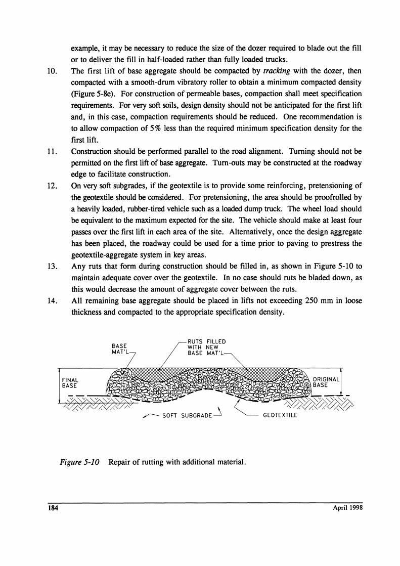
example, it may be necessary to reduce the size of the dozer required to blade out the fill
or to deliver the fill in half-loaded rather than fully loaded trucks.
10. The first lift of base aggregate should be compacted by tracking with the dozer, then
compacted with a smooth-drum vibratory roller to obtain a minimum compacted density
(Figure 5-8e). For construction of permeable bases, compaction shall meet specification
requirements. For very soft soils, design density should not be anticipated for the first lift
and, in this case, compaction requirements should be reduced. One recommendation is
to allow compaction of 5 % less than the required minimum specification density for the
first lift.
11. Construction should be performed parallel to the road alignment. Turning should not be
permitted on the first lift of base aggregate. Tum-outs may be constructed at the roadway
edge to facilitate construction.
12. On very soft subgrades, if the geotextile is to provide some reinforcing, pretensioning of
the geotextile should be considered. For pretensioning, the area should be proofrolled by
a heavily loaded, rubber-tired vehicle such as a loaded dump truck. The wheel load should
be equivalent to the maximum expected for the site. The vehicle should make at least four
passes over the first lift in each area of the site. Alternatively, once the design aggregate
has been placed, the roadway could be used for a time prior to paving to prestress the
geotextile-aggregate system in key areas.
13. Any ruts that form during construction should be filled in, as shown in Figure 5-10 to
maintain adequate cover over the geotextile. In no case should ruts be bladed down, as
this would decrease the amount of aggregate cover between the ruts.
14. All remaining base aggregate should be placed in lifts not exceeding 250 mm in loose
thickness and compacted to the appropriate specification density.
184
FINAL BASE
BASE MAT'l
RUTS FIllED WITH NEW BASE MAT'l
,,---- SOFT SUBGRADE ~
Figure 5-10 Repair of rutting with additional material.
ORIGINAL ~"=\BASE
April 1998
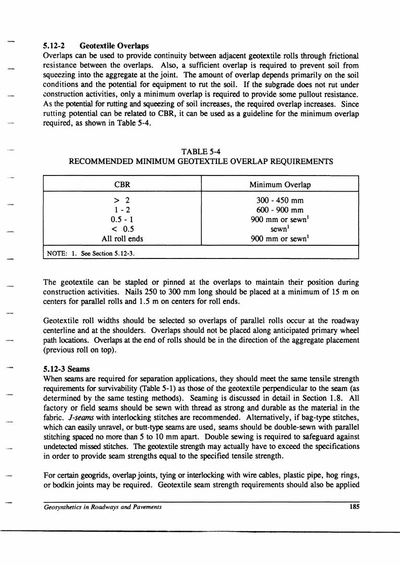
5.12-2 Geotextile Overlaps Overlaps can be used to provide continuity between adjacent geotextile rolls through frictional resistance between the overlaps. Also, a sufficient overlap is required to prevent soil from squeezing into the aggregate at the joint. The amount of overlap depends primarily on the soil conditions and the potential for equipment to rut the soil. If the subgrade does not rut under construction activities, only a minimum overlap is required to provide some pullout resistance. As the potential for rutting and squeezing of soil increases, the required overlap increases. Since rutting potential can be related to CBR, it can be used as a guideline for the minimum overlap required, as shown in Table 5-4.
TABLE 5-4 RECOMMENDED MINIMUM GEOTEXTILE OVERLAP REQUIREMENTS
CBR Minimum Overlap
> 2 300 - 450 mm 1 - 2 600 - 900 mm
0.5 - 1 900 mm or sewn! < 0.5 sewn!
All roll ends 900 mm or sewn!
NOTE: 1. See Section 5.12-3.
The geotextile can be stapled or pinned at the overlaps to maintain their position during construction activities. Nails 250 to 300 mm long should be placed at a minimum of 15 m on centers for parallel rolls and 1.5 m on centers for roll ends.
Geotextile roll widths should be selected so overlaps of parallel rolls occur at the roadway centerline and at the shoulders. Overlaps should not be placed along anticipated primary wheel path locations. Overlaps at the end of rolls should be in the direction of the aggregate placement (previous roll on top).
5.12-3 Seams When seams are required for separation applications, they should meet the same tensile strength requirements for survivability (Table 5-1) as those of the geotextile perpendicular to the seam (as determined by the same testing methods). Seaming is discussed in detail in Section 1.8. All factory or field seams should be sewn with thread as strong and durable as the material in the fabric. J-seams with interlocking stitches are recommended. Alternatively, if bag-type stitches, which can easily unravel, or butt-type seams are used, seams should be double-sewn with parallel stitching spaced no more than 5 to 10 mm apart. Double sewing is required to safeguard against undetected missed stitches. The geotextile strength may actually have to exceed the specifications in order to provide seam strengths equal to the specified tensile strength.
For certain geogrids, overlap joints, tying or interlocking with wire cables, plastic pipe, hog rings, or bodkin joints may be required. Geotextile seam strength requirements should also be applied
Geosynthetics in Roadways and Pavements 185
to overlapped or mechanically fastened geogrids. Consult the manufacturer for specific recommendations and strength test data.
5.13 FIELD INSPECTION
The field inspector should review the field inspection guidelines in Section 1.7. Particular attention should be paid to factors that affect geotextile survivability: subgrade condition, aggregate placement, lift thickness, and equipment operations.
5.14 SELECTION CONSIDERATIONS
For a geotextile to perform its intended function as a separator in a roadway, it must be able to tolerate the stresses imposed on it during construction; i. e., the geotextile must have sufficient survivability to tolerate the anticipated construction operations. Geotextile selection for roadways is usually controlled by survivability, and the guidelines given in Section 5.5 are important in this regard. As mentioned, the specific geotextile property values given in Table 5-2 are minimums. For important projects, you are strongly encouraged to conduct your own field trials, as described in Section 5.5.
5.15 REFERENCES
References quoted within this section are listed below. Additional discussion on recent roadway research is presented in Appendix G. Detailed lists of specific ASTM and GRI test procedures are presented in Appendix E. The Koerner (1994) is a recent, comprehensive textbook on geosynthetics and is a key reference for design. This and other key references are noted in bold type.
AASHTO, Standard Specifications/or Geotextiks - M 288, Standard Specifications (or Transportation Materials and Method! of Samplin& and Tett.in&, 181h Edition, American Association o( State Transportation and Highway Officials, Washington, D.C., 1997.
AASHTO, Task Force 25 Report - Guide Specifications and Test procedures for Geotextiles, Subcommittee 00 New Highway Materials, American Association of State Transportation and Highway Officials, Washington, D.C., 1990.
AASHTO, Interim Guide/or the Design 0/ Pavement Structures, American Association of State Transportation and Highway Officials, Washington, D.C., 1972.
ASTM, Soil and Rock (II): D 4943 - imestj Geosynthetics, Annual Book o( ASTM Standards, Section 4, V olwoe 04.09, American Society (or Testing and Materials, Wett Conshohocken, PA, 1997, 1246 p.
ASTM Test Methods - see Appendix E.
Barksdale, R.D., Brown, S.F. and Chan, F., Potential Benefits of Geosynthetics in Flexible Pavement Systems, National Cooperative Highway Retearch Program Report 315, Transportation Retearch Board, Washington, D.C., 1989, 56 p.
186 April 1998

Baumgartner, R.H., Geotextile Design Guidelines for Permeable Bases, Federal Highway Administration, Washington, D.C., June, 1994,33 p.
Cedergren, H.R., Draina!:e of Hiibway and Airfield Pavements, Krieger, 1987,289 p.
Chan, F., Barksdale, R.D. and Brown, S.F., Aggregate Base Reinforcement of Sulface Pavements, Geotextiles and Geomembranes, Vol. 8, No.3, 1989, pp. 165-189.
Christopher, B.R. and Holtz, R.D., Geotextile En!:ineerin!: Manual, Report No. FHW A-TS-86/203, Federal Highway Administration, Washington, D.C., Mar 1985, 1044 p.
Christopher, B.R. and Holtz, R.D., Geotextilesfor Subgrade StabiliuUion in PemuJnent Roads and Highways, ProceediD8s of Geosyntbetics 191, Atlanta, GA, Vol. 2, 1991, pp. 701-713.
Federal Aviation Administration, Engineering Brief No. 49, Geogrid Reinforced Base Course, U.S. Department of Transportation, 1994.
FHW A, Geotextile Design Examples, GeoServices, Inc., Federal Highway Administration, Contract No. DTFH-86-R-00102, Washington, D.C., 1989.
Giroud, J.P. and Noiray, L., Geotextile-Reinforced Unpaved Roads, Journal of the Geotechnical Enl:ineerinl: Diyision, American Society of Civil Engineers, Vol 107, No GT 9, Sep 1981, pp. 1233-1254.
Haas, R, Granular Base Reinforcement of Flexible Pavements Using Tensar Geogrids, Technical Note BRl, The Tensar Corporation, Atlanta, GA, 1986,22 p.
Haas, R., Walls, J. and Carroll, R.G., Geogrid Reinforcement of Granular Base in Flexible Pavements, presented at the 67th Annual Meeting, Transportation Research Board, Washington, D.C., 1988.
Haliburton, T.A., Lawmaster, J.D. and McGuffey, V.C., Use of EPl:iPeerinl: Fabrics in Trapsportatiop Related Applications, FHWA DTFH61-80-C-00094, 1981.
Hamilton, J.S. and Pearce, R.A., Guidelines for Design of Flexible Pavements using Mirafi Woven Stabilization Fabrics, Law Engineering Testing Co. Report to Celanese Corp., 1981, 47 p.
Illinois Department of Transportation, Design Manual - Section 7: Pavement Design, 1-82-2, Bureau of Design, Springfield, 1982.
Koerner, R.M., Designing With Geosynthetjcs, 3rd Edition, Prentice-Hall Inc., Englewood Cliffs, NJ, 1994, 783p.
Koerner, R.M., Editor, The Seaming of Geosynthetics, Special Issue, Geotextiles and Geomembrapes, Vol. 9, Nos. 4-6, 1990, pp. 281-564.
Miuara, N., Sakai, A., Taesiri, Y., Yamanouchi, T. and Yasuhara, K., Polymer Grid Reinforced Pavement on Soft Clay Grounds, Geotextiles and Geomembranes, Vol. 9, No. I, 1990, pp. 99-123.
Rankilor, P.R., Membranes ip Ground EPl:ipeeriPl:, John Wiley & Sons, Inc., Chichester, England, 1981, 377 p.
Steward, J., Williamson, R. and Mohney, J., Guidelinesfor Use of Fabrics in Construction and Maintenance of Low-Volume Roads, USDA, Forest Service, Portland, OR, 1977. Also reprinted as Report No. FHWA-TS-78-20S.
Terzahgi, K. and Peck, R.B., Soil Mechanics in EPl:iPeeriPI: Practice, John Wiley & Sons, New York, 1967, 729p.
Geosynthetics in Roadways and Pavements 187

Webster, S.L., Geol:rid Reinforced Base Courses for Flexible Pavements for LiKht Aircraft: Test Section Construction. Behayior Under Traffic. Yborato[)' Tests. and Desil:D Criteria, USAE Waterways Experiment Station, Vicksburg, MS, Technical Report GL-93-6, 1993, 100 p.
Yoder, E.J. and Witczak, M.W., Principles ofPavemeut Desil:D, Second Edition, Wiley, 1975,711 p.
188 April 1998