
Georgia Tech A.R.E.S. Project Name: KRIOS Georgia Institute of...
135
By: Georgia Tech A.R.E.S. NASA Student Launch 2017 Project Name: KRIOS March 6th, 2017 Georgia Institute of Technology School of Aerospace Engineering 270 Ferst Drive, Atlanta GA 30332 - 0150
Transcript of Georgia Tech A.R.E.S. Project Name: KRIOS Georgia Institute of...

By:
Georgia Tech A.R.E.S.
NASA Student Launch 2017
Project Name: KRIOS
March 6th, 2017
Georgia Institute of Technology
School of Aerospace Engineering
270 Ferst Drive, Atlanta GA 30332 - 0150

Table Of Contents
1. Introduction
1.1. Team Summary
1.2. Work Breakdown Structure
1.3. Launch Vehicle Summary
1.4. Avionics Summary
1.5. Control System Summary
1.6. Structural Changes since CDR
1.7. Roll Changes since CDR
1.8. Project Plan Changes
2. Project KRIOS Overview
2.1. Mission Statement
2.2. Mission Objectives and Mission Success Criteria
2.2.1 Mission Objectives
2.2.2 Mission Success Requirements
3. Launch Vehicle
3.1. Overview
3.1.1. Rocket Requirements and Specifications
3.1.2. Assembly of Sections
3.2 Launch Vehicle Features
3.2.1 Nosecone GPS
3.2.2 Payload Section
3.2.3 Avionics Bay
3.2.4 Booster Section
3.2.5 Fins and Ailerons
3.2.6 GPS Bay

3.2.7 Final Motor Selection
3.3. Structural Elements
3.3.1. Structure Components Analysis
3.3.2. Thrust Plate Analysis
3.4 Mass Breakdown
3.5 Mission Performance
3.5.1 Mission Performance Overview
3.5.2 Mission Performance Criteria
3.5.3 Mission Performance Predictions
3.5.4 Aerodynamics Analysis
3.5.5 Aerodynamic Locations
3.5.6 Kinetic Energy Breakdown
3.5.7 Drift Profile
3.5.8 Mass Addition System
3.5.8.1 Mass Addition System Predictions
3.5.8.2 Reliability and Confidence
3.6 Recovery Subsystem
3.6.1 Recovery System Overview
3.6.2 Structural and Electrical Elements
3.6.3 Parachute Analysis
3.7 Full Scale Test Flight
3.7.1 Full Scale Recovery System Test
3.7.2 Flight Data
3.7.3 Flight Analysis
3.7.4 Mass Addition System Effectiveness
3.7.5 Roll Control System Effectiveness
3.8 Testing
3.8.1 Ejection Charge Simulation
3.8.2 Parachute Deployment Simulation

3.8.3 Load Testing
3.8.4 Wind Tunnel Testing
3.8.5 Other Testing
3.8.6 Various Failure Modes
3.9. Manufacturing Process
3.9.1 Access
3.9.2 Fabrication Tasks
3.9.3 Machining Plywood
3.9.4 Fabrication Using 3D Printers
3.9.5. Machining Aluminum Alloys
3.9.6. Machining Fiberglass
3.10 Payload Integration
4. Roll Control Criteria
4.1 Roll Control Overview
4.2 Roll Control Features
4.3 Structural Elements
4.4 Precision and Repeatability
4.5 Performance Predictions
5. Electrical Subsystem
5.1 Flight Systems Overview
5.2 Flight System Features
5.2.1 Launch Vehicle
5.2.2 Roll Control
5.3 Flight Systems Software
5.4 Recovery System Electronics
5.5 Workmanship
6. Safety and Launch Operations Procedure
6.1 Personal Hazards Analysis
6.2 Failure Modes and Effect Analysis

6.3 Mitigations List
6.4 Environmental Hazards Analysis
6.5 Launch Operations Procedure
6.6 Launch Operations Checklist
7. Project Plan
7.1 Budget Plan
7.2 Funding Plan
7.3 Timeline
7.3.1 Gantt Chart
7.4 Educational Engagement Plan and Status
7.4.1 Overview
7.4.2 Engineering Merit Badge
7.4.3 Peachtree Charter Middle School
7.4.4 Atlanta Science Festival
7.5 Team Derived Requirements
7.6 Verification Plan

1. Introduction
1.1. Team Summary
Table 1.1.1: Team Summary
Team Summary
School Name Georgia Institute of Technology
Mailing Address 270 Ferst Drive, Atlanta GA 30332 - 0150
Team Name Team A.R.E.S. (Autonomous Rocket Equipment System)
Project Title Mile High Club
Rocket Name KRIOS
Project Lead Sam Rapoport
Project Lead E-mail [email protected]
Team Email [email protected]
Safety Officer Vikas Molleti
Team Advisor Dr. Eric Feron
Team Advisor e-mail [email protected]
NAR Section Primary: Southern Area Launch Vehicle (SoAR) #571
NAR Contact, Number &
Certification Level
Gerardo Mora
NAR Number: 98543
Certification Level: Level 2 Certified for HPR by NAR

1.2. Work Breakdown Structure
Team Autonomous Rocket Equipment System (A.R.E.S.) is composed of 22 students
studying various fields of engineering. Our team is composed of less than 50% Foreign Nationals
(FN) per NASA competition requirements. To work more effectively, the team is broken down
into groups that focus on special tasks. Each sub-team has a lead supported by several
specialized task groups. Team memberships were selected based on each individual's area of
expertise and personal interest. Figure 1.2.1 shows the work breakdown structure of Team
ARES.

Figure 1.1.1: Team Structure
1.3. Launch Vehicle Summary
KRIOS is 102 inches long and 5.5 inches outer diameter When loaded, weighing 33.4
pounds when loaded. The rocket is wide enough to house all avionics while maintaining a
sufficient stability. At the bottom of each fin is an aileron mounted on a hinge. These ailerons are
actuated by servos mounted at the bottom of the booster section. This actuation will induce the
moment needed to accomplish the “roll” mission objective. The Mass Addition System is located
in the GPS bay in the Nose Cone. Its purpose is to house any ballast needed to adjust the rocket’s
center of mass to match the simulations that have been conducted. Above the Motor is the
Weight Addition Transmission Equipment System (WATES). It consists of a sealed
compartment with a removeable PVC cap. If, after construction, the rocket was found to have
less mass than anticipated, sand could have been added to WATES to increase the overall mass.
WATES is located near the rocket’s center of mass, so adding mass in this location would not
greatly affect the center of mass.
1.4. Avionics Summary The main components of the avionics of system of the Krios are listed as follows: two
stratologgerCF altimters to ensure a dual redundant recovery, the Pixhawk px4 autopilot system, used as
an external IMU and data collection device, and the MBED
1.5. Control System Summary
Team ARES’s payload will consist of an experimental control system. The mission is to
induce a roll and counter roll post motor burnout. Roll will be controlled by ailerons located on
the trailing edge of each fin. Each aileron is individually controlled by a servo, and each servo
assembly is mechanically linked by a common gears. The servos will receive commands from a
Pixhawk collecting gyroscopic and air-speed data.

1.6. Structural Changes Since CDR
There have been some very minor changes to the structure of the rocket. The length of
both parachute compartments have been decreased due to the realization that the packing
volume was significantly less than what was estimated. To keep a similar stability, the MAS
compartment was increased such that the overall length of the rocket did not change.
1.7 Avionics Changes since CDR
The recovery system of the rocket has not changed since the submission of the CDR.
The roll system of the rocket has undergone adaptations due to difficulties surrounding the
Pixhawk autopilot system.
As discussed in the CDR, the Pixhawk px4 is an autopilot system designed for RC copters and
fixed wing aircrafts. The board is designed with users of these vehicles in mind and, therefore,
only offers firmware to support the motor control of these types of aircrafts. The original plan
was to code a custom firmware for the purpose of our flight in C++, bypass the system’s GUI,
and flash our custom build onto the board. However, the development guide for the Pixhawk is
still in its beta stages and lacks the resources to complete such a project in a timely manner.
Because the motors on the launch vehicle serve a far different function than those found on the
RC crafts, the px4 will no longer be responsible for actuating the servo motors of the vehicle.
Instead, an MBED ARM microcontroller will fulfill this role within the roll system of the rocket.
The MBED is coded using C++ and has an expansive and well established developer’s library
for creating custom builds. The Pixhawk, equipped with 9DOF IMU, dedicated telemetry, and
data acquisition capabilities, is still responsible for streaming sensor data to the MBED and
reporting the official roll path of the rocket. The fixed wing firmware will be flashed to the
board with many features disabled. This decision was made to ensure that our system is both
reliable and achievable.

1.8. Roll Control Changes Since CDR
Changes to the Roll Control System since the CDR have been minimal. The servos which
actuate the ailerons are now mounted to a bottom plate now sit on an ABS plastic mount. This
mount was added to ensure that the servo would remain secured in place during flight and to
more easily allow wires to be routed through the compartment. Additionally, the shaft in the
ailerons’ shaft has been changed from a square shaft to a D-shaft. A D-shaft was chosen to make
assembly less complex
1.9. Project Plan Changes
● Available funding expanded to $7000
● Peachtree Charter Outreach timeline slowed due slow response times
● Permanent access to rocket construction area acquired
● Student Foundation funding unsuccessful, however funding still exceeds budget
● March 4th Launch unsuccessful- plan to launch in future and participate in USLI

2. Project KRIOS Overview
2.1. Mission Statement
To maintain a sustainable team dedicated to the gaining of knowledge through the
designing, building, and launching of reusable launch vehicles with innovative payloads in
accordance with the NASA University Student Launch Initiative Guidelines. Project KRIOS
specifically will launch a rocket reaching as close to an apogee of 5280 ft as possible, induce a
roll of at least 2 rotations with counter roll, and further community enthusiasm for STEM and
rocketry.
2.2. Mission Objectives and Mission Success Criteria
2.2.1 Mission Objectives
Table 6.2.1. Verification Plan
Requirement Design Feature Verification
Vehicle altimeter will report
an apogee altitude of most
nearly 5,280 feet AGL.
The size and strength of the
motor will be
selected to ensure an apogee
of 5280 ft
Gathering data post-launch
from on-board
altimeters
Launch vehicle will be
designed to be recoverable
and reusable within the day
of initial launch.
Vehicle will be constructed of
fiberglass to
resist fractures and ensure
stability.
By inspecting every element
of the launch
vehicle post recovery
Vehicle will require minimal Modular/flexible assembly Conduct evaluation of time

assembly/disassembly time
and effort
construction required to
assemble/disassemble key
components of vehicle
The vehicle will complete
two
rolls and then produce a
counter-roll
The roll system will deploy
post motor burnout
by actuating flaps on the
fins to create asymmetrical
drag and generate roll.
Gathering data post-launch
from the onboard
gyroscope and onboard
cameras
The launch vehicle shall have
a maximum of four (4)
independent sections.
Three (3) sections include:
payload/nosecone,
avionics, and booster
Observe separated sections
during descent
The vehicle will be limited to
a single stage, solid motor
propulsion system, delivering
an impulse of no
more than 5,120
Newton-seconds.
Design using one L-class
motor
Control installation process
The launch vehicle shall stage
the deployment of its
recovery devices, where a
drogue parachute is deployed
at apogee and a main
parachute is deployed at a
much lower altitude.
All recovery systems will be
dual-redundant to
ensure deployment at a safe
altitude
Observe flight data to check
for separation and
parachute deployment at
correct altitudes
At landing, the launch vehicle
shall have a maximum
Main parachute selected by
deriving Kinetic
Evaluate post-recovery
altimeter data to check

kinetic energy of 75 ft-lbf. Energy for heaviest
independent section
impact velocity
The recovery system will
contain redundant
altimeters, each with their
own power supply and
dedicated
arming switch located on the
exterior of the rocket airframe
Install a master key-switch at
the rear of the
avionics bay to close all
circuits simultaneously
Analyze altimeter data
post-launch
Each detachable section of
the vehicle and
payload must contain an
electronic tracking device and
continue transmission
to the ground throughout
flight and landing.
Will implement and test a
GPS system with proper
shielding and protection to
ensure vehicle tracking
Track each section of vehicle
in-flight
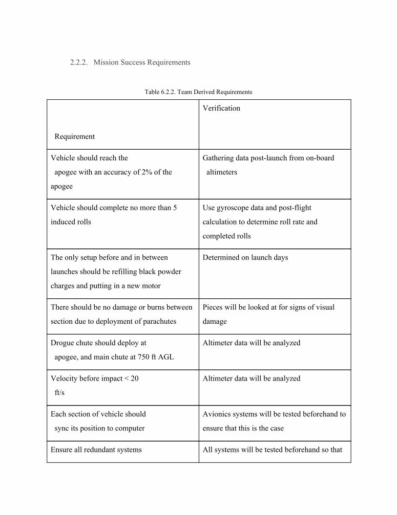
2.2.2. Mission Success Requirements
Table 6.2.2. Team Derived Requirements
Requirement
Verification
Vehicle should reach the
apogee with an accuracy of 2% of the
apogee
Gathering data post-launch from on-board
altimeters
Vehicle should complete no more than 5
induced rolls
Use gyroscope data and post-flight
calculation to determine roll rate and
completed rolls
The only setup before and in between
launches should be refilling black powder
charges and putting in a new motor
Determined on launch days
There should be no damage or burns between
section due to deployment of parachutes
Pieces will be looked at for signs of visual
damage
Drogue chute should deploy at
apogee, and main chute at 750 ft AGL
Altimeter data will be analyzed
Velocity before impact < 20
ft/s
Altimeter data will be analyzed
Each section of vehicle should
sync its position to computer
Avionics systems will be tested beforehand to
ensure that this is the case
Ensure all redundant systems All systems will be tested beforehand so that

are powered and capable the validity of their redundancy is legitimate
Ability to access components
without compromising rocket in any way
Ease of access will be determined on launch
day and through various stages of testing

3. Launch Vehicle
3.1. Overview
3.1.1. Rocket Requirements and Specifications
Our team has designed the Krios rocket to fulfill all of the mission objectives described in
section 2.2 as safely and effectively as possible. The rocket is 102 inches long and 5.5 inches
wide. When loaded, The weight is approximately 33.4 pounds. The rocket is wide enough to
house all avionics while maintaining a sufficient stability margin of 2.56.
The Nose Cone, like the rest of the airframe, is fiberglass. The GPS unit and its power
supply are located in the nose cone to ensure that they are far enough from the avionics
equipment to not be affected by electromagnetic interference. The Avionics Bay is located near
the middle of the rocket, between the main chute and drogue chute. It houses the Pixhawk
microcontroller, its power supply, and the primary and backup altimeters. The fins provide
stability. At the bottom of each fin is an elevon mounted on a hinge. These elevons are actuated
by servos mounted at the bottom of the booster section. This actuation will induce the moment
needed to accomplish the “roll” mission objective. The Mass Addition System is located in the
GPS bay in the Nose Cone. Its purpose is to house any ballast needed to adjust the rocket’s
center of mass to match the simulations that have been conducted. Above the Motor is the
Weight Addition Transmission Equipment System (WATES). It consists of a sealed
compartment with a removeable PVC cap. If, after construction, the rocket was found to have
less mass than anticipated, sand could have been added to WATES to increase the overall mass.
WATES is located near the rocket’s center of mass, so adding mass in this location would not
greatly affect the center of mass. After the rocket was constructed, we decided that additional
mass was not needed, so WATES is empty.

3.1.2. Assembly of Sections
The different sections of the rocket are held together by friction with the couplers and
shear pins. The shoulder of the Nose Cone fits into the Upper Transition Tube. The Avionics bay
acts as a coupler between the Upper Transition Tube and the Main Body Tube. The fins fit into
slots in the Main Body Tube. They epoxied to the outside of the Main Body Tube as well as
Centering Rings inside the tube to ensure secure attachment. The Centering rings are epoxied to
the Engine Mount which contains the Motor Casing. A Thrust plate is epoxied to the Main Body
Tube above the engine mount, and the Bottom Plate is screwed to the Main Body Tube below the
Engine Mount. The Bottom Plate also supports the servos for the Roll System, which are
mounted on 3D printed Servo Brackets.
3.2 Launch Vehicle Features
3.2.1 Nosecone GPS
The purpose of installing a separate, isolated GPS system in the nose cone was to ensure
that no detrimental electromagnetic interference would be likely to occur. Interference was seen
as a possible issue if the GPS was located in the avionics bay due to the high concentration of
crucial flight control electronics. An additional benefit of the nose cone placement is that the
GPS system is farther from the recovery system charges and therefore in a lower pressure and
thereby safer area for the durability of the GPS system as a whole.

GPS Bay on Rocket
The GPS is housed in the GPS Bay, which shares space with the Mass Addition System.
Both are located within the PVC pipe near the nose cone. The GPS Bay is well separated from
the Mass Addition System because the GPS and its equipment, including a 9 V battery are to be
placed inside a foam insert. The foam insert has holes cut out to make the exact amount of space
for the GPS. The reason the GPS is to be placed in the foam is to help cushion the impact of the
launch and the fall. The ends of the PVC pipe are capped on both ends. The GPS assembly is
held in place by the centering rings which are epoxied to the pvc pipe and to the inside of the
nose cone up to the cone shoulder. They were epoxied to ensure that the entire system is kept
safe and doesn’t move during the launch or when the rocket is airborne.

Exploded GPS Capsule
3.2.3 Avionics Bay
The purpose of the Avionics Bay (A-Bay) is to contain, protect, and enable the function
of all avionics components. Additionally, it serves as a separator between the main and drogue
parachutes. Avionics are mounted to a removable sled inside of the bay. The A-Bay is sealed on
both ends to protect the electronics from hot ejection gases. The fiberglass structure shields the
avionics from any impacts experienced during flight. A hole in the A-Bay enables the avionics to
measure the barometric pressure of the atmosphere surrounding the vehicle. Figure 3.2.1 shows
the location of the A-Bay in the rocket.


Figure 3.2.1 Avionics Bay Location
When designing the A-Bay, we decided to place it on a sled rather than attach it to the
airframe body due to the safety and accessibility improvements. By being on a sled attached to
multiple bulkheads at multiple locations, the components of the A-Bay would be stable from
ejection charge discharges and other events that would cause instability within the rocket. In
addition, a removable tray would allow for easy modification of A-Bay components as well as
data collection after flights. As the components of the A-Bay are necessary for a proper flight,
the removable nature of the tray allows for emergency maintenance, such as battery replacement.
The Avionics Bay (A-Bay) is housed inside of a 12in section of fiberglass coupler tube.
Avionics components are mounted onto a 9.75in by 3.25in plywood sled contained in the
coupler. Two 14in long threaded rods are attached along the length of the sled, so that the extend
out of the coupler. On the aft end of the A-Bay, the rails run through and are attached to a
fiberglass cap. This cap is formed by connecting together two concentric disks: one with the
same outer diameter as the coupler, and one with the same inner diameter as the coupler. A
second cap, which is free, is slid of the rails at the top of the A-bay. This cap is secured by nuts
placed over the threaded rail. When the nuts are tightened, both caps are pulled against the edge
of the coupler, forming a seal.
Figure 3.2.2 Empty Avionics Bay

Figure 3.2.3 Exploded View
Figure 3.2.4 Tray With Mounted Hardware

3.2.4 Booster Section
The booster section assembly has not changed since the submission of the CDR. A .5 in
thrust plate resides on the end of a 75mm LOC tube, which houses the motor. There are 3
centering rings, two within the fin and one at the end of the LOC tube. Every plate/ring going
down from the avionics bay was designed with the intention of eventually being drilled and
assembled with avionics equipment to pass wiring through all parts of the rocket down to the
servos.
Figure 3.2.5 CAD Booster Tube
The entirety of the booster section, which comprises of the mounting of the 4 fins to their
respective ailerons, as well as the mounting of the fins to the LOC and fiberglass tubes remained
unchanged. The only problem identified with this design was that with constant removeall of the
servo+pinion gear plate on the bottom of the rocket, it becomes very difficult to lign up the gear
perfectly enough to ensure a good mash.

Figure 3.2.6 CAD Booster Section
Figure 3.2.7 Fabricated Booster Section

3.2.5 Fins and Ailerons
The fins and elevons of KRIOS are made of G10 fiberglass. The aft end of the fins and
forwards end of the ailerons have rectangular depressions machined into them which allow them
to interface with the roll control system via aluminum brackets.
Figure 3.2.5 Fin + Aileron Assembly

3.2.6 GPS Bay
The Mass Addition System is coupled with the GPS Bay. They are both housed in the
same component. The Mass Addition System is held towards the top of the rocket near the
nose-cone. The system along with the GPS bay are housed in a PVC pipe. The PVC pipe is
capped on both ends. The mass is added to the system in the form of sand. The PVC pipe is
epoxied to the the centering rings, and the centerings rings are epoxied up to the inside of the
nose cone shoulder.
Figure 3.2.6 GPS Bay
Figure 3.2.7 EndCap

The location of Mass Addition System is important because it is situated towards the top
of the rocket. Any addition of mass would have a bigger impact on the center of gravity (CG) of
the rocket. If, after the construction of the rocket, the CG is slightly lower than was anticipated,
extra mass could be added to the Mass Addition System to move the CG back to what was
initially calculated.
Mass Addition System
3.2.7 Final Motor Selection
The final motor selected remains the Aerotech L1150. The expected apogee given its
thrust profile is within 5 feet of 5280ft. The data of the L1150 is below in table 3.2.5 and the
thrust profile in figure 3.2.5.

Aerotech L1150
Diameter 75.00 mm
Length 53.1 cm
Propellant Weight 2065.3g
Overall Weight 3,673.6g
Average Thrust 1,102.2 N
Maximum Thrust 1,309.7 N
Total Impulse 3,488.6 Ns
Specific Impulse 96.9s?
Burn Time 3.2s
Table 3.2.5- Aerotech L1150 Specifications

Figure 3.2.5 Thrust Curve Profile for L1150
3.3. Structural Elements
It was necessary to test different components of the rocket prior to full assembly, due to
the risk involved with the failure of these components. If a bulkhead failed in flight, parachute
deployment would not be successful, as a proper connection between the bulkheads and the
airframe is necessary for the parachutes to work properly. In addition, if the avionics bay
bulkheads failed, the altimeters and other electronics equipment would be put at risk of damage,
which may interfere with parachute deployment and data collection. Therefore, the bulkheads of
the rocket required the most structural analysis, to confirm that these components could
withstand the forces of a rocket launch.
During the rocket’s flight, the bulkheads would experience two major forces: the pressure
from the ejection charge explosion during parachute deployment, and the impulse from the shock
cord as the parachute deployed. In both of these situations, the components with a likelihood of
failing were the fiberglass bulkheads themselves and the epoxy that held the bulkheads to the

body tubes. To test these components, it was necessary to first calculate the forces exerted on
each, perform simulations on Solidworks, then design and perform physical load tests to
determine if the simulations were accurate. Figure 3.3.1 below shows each bulkhead to be tested,
as well as its location in the rocket.
Figure 3.3.1 Bulkhead Locations
3.3.1. Ejection Charge Simulation
The first internal force exerted on the bulkheads adjacent to both the main parachute and
drogue parachute would be from the detonation of black powder ejection charges to snap the
shock cords. Table 3.3.1. details the pressure of each charge on the bulkheads.

Table 3.3.1 Pressure from Ejection Charges
Bulkhead Amount of black
powder(grams)
Volume of
compartment(in3)
Pressure on bulkhead
(psi)
Main 1 3 594.8 9.9
Main 2 3 594.8 9.9
Drogue 1 3 297.4 19.8
Drogue 2 3 297.4 19.8
When first conducting the simulation tests on Solidworks, it was necessary to create the
fiberglass material, as it was not one of the presets on the software. Using data sheets for G10
fiberglass, the material was created and applied to the parts in the CAD model. When testing
each bulkhead, a fixed geometry was assumed, chosen based on the area of the component that
was fixed in place. For the avionics bay bulkheads, the fixed geometry was the intersection of the
bulkhead and the threaded rod that connected the two. This was represented by the inside of the
two holes on either side of the bulkhead, as this was where the threaded rod was placed. In order
for this fixed geometry to fail, the nuts would have to fail or the threads of the rods themselves
would have to be destroyed, something that was unlikely to occur. For the other bulkheads, the
fixed geometry was on the outside circumference of the bulkheads, where epoxy connected them
to the body tube. The assumption in this case was that the fiberglass bulkheads would fail before
the cured, crosslinked epoxy bond. The pressure was then applied to the plate. The figures below
show the results of the tests from the ejection charges. Every bulkhead successfully withstood
the simulated pressure from the respective charge detonations.

Figure 3.3.2. Main 1 Ejection Charge Test
Figure 3.3.3. Main 2 Ejection Charge Test

Figure 3.3.4. Drogue 1 Ejection Charge Test
Figure 3.3.5. Drogue 2 Ejection Charge Test

3.3.2 Parachute Deployment Simulation
The next force that each bulkhead experiences would be an impulse from parachute
deployment. Each parachute deployment would drastically reduce the downwards acceleration of
the rocket, and would create an upwards force on the bulkhead due to Newton’s First Law. Using
OpenRocket simulations, we measured the acceleration of the rocket at different wind speeds,
and with the mass of the rocket, we were able to measure the maximum force on a bulkhead at
each given time. For these tests, Main Bulkhead 2 and Drogue Bulkhead 2, as those sections
would support the most mass of the rocket after parachute deployment and therefore experience
the most force. Table 3.3.2 details the acceleration and force on the bulkheads. In terms of the
OpenRocket software, as seen in Figure 3.3.6, the exact location characteristics of the Huntsville,
AL launch site were inputted into the program to ensure that the proper scenario is put into play
when running the simulations, such as the coordinates, altitude, etc.
Figure 3.3.6 from OpenRocket Simulations

Table 3.3.2 Force from Parachute Deployment
Wind Speed
(mph)
Mass of Rocket
(kg)
Mass of
Booster/Avionics
Bay(kg)
Acceleration
(m/s2)
Force (N) on
Main 2
5 13.232 12.706 78.5 997.421
10 13.232 12.706 78.5 997.421
15 13.232 12.706 78.6 998.711
20 13.232 12.706 78.6 998.711
Wind Speed (mph) Mass of Booster (kg) Acceleration (m/s2) Force (N) on Drogue 2
5 9.469 78.5 743.296
10 9.469 78.5 743.296
15 9.469 78.6 744.243
20 9.469 78.6 744.243
Using the same fixed geometries assumed during ejection charge testing, these forces
were tested in the SolidWorks Simulations add-on. The worst-case scenario force was 998.711
N, so this was used during the testing. The figures below show the results of the simulation tests.
Each bulkhead successfully withstood the maximum possible force.

Figure 3.3.7 Main 2 Parachute Deployment
Figure 3.3.8 Drogue 2 Parachute Deployment
All structural components withstood the simulated stress. The next step was to construct
physical mockups of the different components for load testing, which is discussed later in the
Testing section.

3.4 Mass Breakdown
The components of KRIOS and their masses are sorted by subsystem below in table
3.4.1.. It can be seen from these tables and figures that the subsystems with the greatest mass are
the Structure of the rocket and Propulsion. The components with the most mass are the motor
and the fiberglass airframe tubes. The rocket’s center of mass is located in the middle of the
Drogue Chute Compartment above the MAS.
Table 3.4.1 Mass Breakdown
System Component Material
Mass per
Unit (lbm) QTY.
Total
Mass (lb)
Nose Cone
Nose Cone Fiberglass 1.07 1 1.07
GPS Bay Tube PVC 0.66 1 0.66
Bottom Nose Cone
Bulkplate Fiberglass 0.27 1 0.27
Top Nose Cone
Bulkplate Fiberglass 0.26 1 0.26
U-Bolt Steel 0.127 1 0.127
GPS Bay Foam Foam 0.09 1 0.09
Nose Cone Weight Lead Shot 2.1 1 2.1
Structure
Upper Transition
Tube Fiberglass 3.06 1 3.06
Main Body Tube Fiberglass 5.28 1 5.28
Drogue Chute Rip-Stop Nylon 0.16 1 0.16

Recovery Main Chute Rip-Stop Nylon 1.07 1 1.07
A-Bay
Airframe Bulkhead Fiberglass 0.37 2 0.74
A-Bay Airframe Fiberglass 0.1 1 0.1
A-Bay Coupler Fiberglass 1.41 1 1.41
Coupler Bulkhead Fiberglass 0.18 2 0.36
Mounting Plate Balsa Wood 0.05 1 0.05
Plate Bracket Aluminum 0.05 4 0.2
Threaded Rod Steel 0.2 2 0.4
Nut Steel 0.01 8 0.08
Batteries N/A 0.96 1 0.96
Blast Cap N/A 0.04 2 0.08
Eye-Bolt Steel 0.11 2 0.22
Hardware N/A
MAS
PVC Cap PVC 0.04 1 0.04
PVC Nozzle PVC 0.02 1 0.02
Compartment PVC 0.42 1 0.42
U-Bolt Steel 0.127 1 0.127
Roll
Flap Bracket Aluminum 0.01 12 0.12
Fin Bracket Aluminum 0.01 12 0.12
D-shaft Steel 0.06 4 0.24
Flap Fiberglass 0.09 4 0.36
Fin Fiberglass 0.75 4 3
Face Gear ABS Plastic 0.41 1 0.41

Small Bevel Gear Brass 0.01 4 0.04
Large Bevel Gear Brass 0.01 4 0.04
Servo Hub Aluminum 0.01 4 0.04
Servo Mount ABS Plastic 0.03 4 0.12
Propulsion
Motor Casing
(loaded) N/A 8.15 1 8.15
Centering Rings Fiberglass 0.13 3 0.39
Thrust Plate Plywood 0.23 1 0.23
Bottom Plate Aluminum 0.21 1 0.21
Bottom Plate Bracket Steel 0.02 4 0.08
Engine Mount Cardboard 0.49 1 0.49
Table 3.4.2 Mass by Subsystem
Subsystem Mass (lb)
Nose Cone 4.577
Structure 8.34
Recovery 1.23
A-Bay 4.3
MAS 0.607
Roll 4.49
Propulsion 9.55
Total 33.394

Figure 3.4.1: Mass Distribution Pie Chart
Figure 3.4.2: Mass Visualization
Table 3.4.3: Mass Visualization Key
Color Mass
Green Greater than 2 lb

Blue Between 0.5 lb and 2 lb
Red Less than 0.5 lb
*Note that the motor appears red because it is inside the Engine Mount, which is made from cardboard and weighs
less than 0.5 lbs. The rocket’s center of mass is shown as the black and white circle.
3.5 Mission Performance
3.5.1 Mission Performance Overview
The success of the mission can be measured by various criteria and the ability of the
rocket flight to meet these objectives. Through OpenRocket and ANSYS simulations, the flight
of the rocket can be tracked to determine if these objectives are expected to be accomplished.
3.5.2 Mission Performance Criteria In order for the mission to be considered a success, the following criteria must be met:
1) The launch vehicle will report an apogee within 2% of 5,280 ft, the target altitude, due to
the Mass Addition System (MAS).
2) The launch vehicle will return reusable, with fully functioning systems and no structural
damage.
3) The roll system completes at least two rolls and produces a counter-roll between time of
motor burnout and time at apogee.
4) The launch vehicle successfully separates into three stages connected via shock cord.
5) The drogue parachute deploys at apogee, and the main parachute deploys at 750 ft above
ground level.
6) The velocity of the launch vehicle before impact is less than 20 ft/s.
7) The GPS successfully remains synced to the computer and reports its position.

3.5.6 Kinetic Energy Breakdown
Just above the avionics bay, before the nosecone, is the main parachute bay. To ensure
that each section of the rocket lands with less than 75lb-ft of Kinetic Energy, a 120” TFP
Parachute has been chosen. This will ensure that our landing velocity falls below 20 ft/s. The
calculations are shown below:
According to OpenRocket, the vehicle will touchdown with a velocity of 18.5ft/s. The
most massive section of the vehicle upon touchdown will be the booster section, with a weight of
220oz. First convert this weight into a mass.
20oz 427 slugs2 *1lbf16oz *
1slug32.17lbf = .
Now kinetic energy may be calculated using the equation:
mvEk = 21 2
404 slugs 18.5 f t/s)Ek = 21 * . * ( 2
7.32 lb tEk = 8 · f
Section Mass(lb) Kinetic Energy (ft-lbf)
Nose Cone 9.177 49.05
Avionics 7.53 40.27
Booster 16.03 87.32

3.5.7 Drift Profile


3.5.8 Mass Addition in GPS Bay
The GPS Bay allows for the addition of mass to the top of the rocket. This is an effective
way to raise the location of the CG if an increase in stability is needed. The Mass is held towards
the top of the rocket inside the nose-cone. The system is essentially in a PVC pipe. The PVC
pipe is capped on both ends. The mass is added to the system in the form of metal weights. The
PVC pipe is epoxied to the the centering rings, and the centerings rings are epoxied up to the

inside of the nose cone shoulder to ensure the Mass Addition System is stable and doesn’t move
during the launch, flight, or landing of the rocket.
One End of the system Opposite end of the system
The location of the added mass is important because it is situated towards the top of the
rocket. Any addition of mass would have a bigger impact on the center of gravity (CG) of the
rocket. If, after the construction of the rocket, the CG is slightly lower than was anticipated, extra
mass could be added to move the CG back to what was initially calculated.

Assembled GPS Bay

3.6 Recovery Subsystem
3.6.1 Recovery System Overview
The recovery system has not changed since the preliminary design or the CDR. At the top
desired high a drogue parachute is deployed in order to start the rocket's descent and to lower its
speed. A second main parachute is deployed closer to the ground to bring the rocket down to the
desired landing speed. Each parachute is deployed using small charges that are set to explode at
the desired heights. Each parachute has a series of redundancies, such as a secondary charge, to
be sure that the parachute will be deployed.
Figure 3.6.1 Parachute Positions in Rocket
3.6.2 Structural and Electrical Elements
The primary component of the recovery system is the Perfectflite StratloggerCF altimeter
which is capable of measuring altitude through a barometric pressure sensor. The StratoLogger
altimeter additionally has the ability to deploy parachutes by ejecting a large output current at the

desired height. Two of these will act as the sole electrical components of the recovery system.
They will both be powered independently and connected to both the main and drogue chutes in
order to ensure dual redundant chute employment. Additionally, one altimeter is set to blow its
charges at a delay of one second. As seen in figure 3.6.2, the StratoLogger CF is an industry
standard model rocketry altimeter. Through its robust and easily modifiable design, it provides a
desired reliability for the recovery system of the rocket.. The stratologger altimeter was
carefully selected in order to ensure successful recovery: the subscale launch confirmed that it
can be both trustworthy and reliable.
Figure 3.6.2 The StratologgerCF altimeters with connection labels
The two stratologger altimeter will be the sole electrical components of the recovery
system. The reason for this is to ensure that the recovery of the rocket is completely independent
of the flight control system system and minimize risk to ensure successful recovery. The
tandem altimeters, each with an independent 9V power supply and their own drogue and main
chute deployment charges create a dual redundant system. If one altimeter were to fail, the other
would be able to recover the rocket. One altimeter is set to have a delayed drogue and main
charge firing so that both blasts will not fire at the same time, which could potentially damage
the rocket. Figure 3.6.3 below depicts the StratologgerCF wiring path and illustrates the dual
redundant system.

Figure 3.6.3: Dual Redundant System
The rocket will have live GPS capabilities through the implementation of the Eggfinder
GPS system; comprised of the RX Receiver module, connected to a ground station, and a TX
transmitter module, embedded into the nosecone of the rocket. The two will communicate
through 900 MHz ISM band signals. 100 mW will enable roughly 10,000 feet of lossless
communication: enough for the purposes of the task at hand. The eggfinder will satisfy the
competition requirement of live tracking capabilities and allow the team to know the exact
latitude and longitude of the rocket throughout the flight, and, more importantly, to find the
rocket upon recovery.

3.6.3 Parachute Analysis
The recovery system will consist of one drogue and one main parachute of 120” and 45”
respectively. A GPS system is placed in the nosecone of the rocket and used in order to locate
the rocket at the landing site. First, a drogue chute will deploy at apogee to slow the rocket’s
descent and stabilize its trajectory, limiting the rocket’s horizontal drift due to air currents. The
drogue chute will be housed above the avionics bay. Once the rocket descends to 750 ft, the main
parachute will deploy, slowing the rocket to a safe landing speed and allowing it to remain intact
upon impact with the ground. The main parachute will be housed below the avionics bay. At
apogee (5280 ft), the ejection charges for the drogue parachute will activate. The drogue
parachute will be deployed to slow and stabilize descent and reduce downrange drift, allowing
for payload and main parachute deployment. Deployment of the main parachute will occur
between 700 ft and 800 ft, further decelerating the rocket so that the impact kinetic energy is
below 75 ft-lbf. The main parachute will also prevent a considerable amount of horizontal
displacement that occurs as a result of wind gusts and drift.
Both parachutes will be fabricated from rip-stop nylon in order to support the weight of
the launch vehicle. Parachutes will be secured in their individual sections using an insulated
material to prevent the ignition of the nylon due to explosive charges that will separate the
different sections of the rocket sections during descent deployed from the blasting caps that are
attached to 0.25 in bulkheads which seal the avionics bay from the rest of the rocket’s
compartments. The parachutes will be attached and secured to the rocket via the shock-cords
which are connected to U-bolts installed onto the respective bulkheads/centering rings insulating
each section of the rocket from pressurization.

Figure 3.6.4 Rip-Stop Nylon Parachute

3.8. Testing
3.8.1 Bulkhead Load Tests
After the bulkheads simulations had been completed, it was necessary to construct and
test a mockup of the different bulkheads to confirm that the simulations were accurate. For this
testing, two different mockups had to be constructed: an avionics bay setup using the threaded
rods, coupler bulkheads, main bulkheads, and eye-bolts used in the actual rocket, and a bulkhead
epoxied to the fiberglass body tube. This would allow us to test the durability of both the
fiberglass bulkhead material and the epoxy bond used in the rocket.
For the main bulkhead mockup we used the waterjet to cut a piece of fiberglass tubing to
the dimensions of the CAD model that was used for simulations of that part. We also waterjetted
the plate to be used for the top. Then we drilled holes in the top for where the u-bolt goes and
drilled four holes around the tube. We mixed epoxy and used it to connect the top plate to the
tubing. It can be seen in Figure 3.8.1 that we created fillets with the epoxy in the figure below.
To simulate the force we tied string to the u-bolt, as it would be in the actual rocket.

Figure 3.8.1 Bulkhead after epoxy
And to hold it down in testing and simulate the force from the other side we strung cord
through the four holes that were drilled into the side of the tubing, as seen in Figure 3.8.9. This
way when put into the stress testing machinery we would be sure that the single point of contact,
the system we were testing, the u-bolt would fail before the other side since it had many points of
contact and therefore spread out the pressure evenly along the whole body of the tubing.

Figure 3.8.2 Mockup with cord
When constructing the avionics bay mockup, it was necessary to construct both sides of
the avionics bay, as the two bulkheads are connected to each other by threaded rods in the full
scale rocket. To create the bulkheads, a waterjet was used, which accurately cut both the coupler
bulkheads and the main bulkheads. However, when using the waterjet on the fiberglass, air
bubbles formed within the fiberglass, due to the high pressure of the water causing a separation
in the fiberglass layers. Therefore, the holes for the threaded rod and the eyebolt had to be drilled
by hand.
To measure the center of the bulkheads, multiple methods were used. First, we drew
multiple chords across each bulkhead, and drew line segments from their midpoints. The
intersection of these lines was the location of the center of the bulkhead. This was not accurate,
however, so we used a caliper and ruler to measure the widest section of the bulkhead, the
diameter, and used its midpoint to determine the center. In order to drill these holes, all four
bulkheads (2 coupler, 2 main) were clamped together, and a hole was drilled at the center
multiple times, with incrementally increasing drill bit sizes. To determine the location of the
threaded rod holes, measurements were taken in the CAD model, and were replicated using a
caliper on the actual bulkheads. Once again, the four bulkheads were clamped together while

drilling to ensure that the holes were at the same location on each. Figure 3.8.3 shows a bulkhead
with the hole locations.
Figure 3.8.3 Bulkhead with Hole Locations
Then, the bulkheads were placed 3 inches apart, a value that allowed them to not be
interfering with each other while minimizing the length of threaded rod used. The rods were
inserted through the holes, and nuts and washers were used to fix the bulkheads in place. The
eyebolts were fastened in a similar fashion. Finally, shock cord was tied to each eyebolt, to
simulate the parachute shock cord connection to the bulkheads. The final assembly is shown in
Figure 3.8.4.

Figure 3.8.4 Avionics Bay Mockup
The impulse from parachute deployment generated a larger force than the ejection charge
detonation, so the parachute deployment force was chosen as the test force.
Testing the mockups required placing them in a tensile tester, which pulled the mockups
from both sides until they failed. To test each mock up, we tied a segment of the shock cord to
either side with a bowline knot, and tested by attaching the shock cord to the tensile tester. Then,
we repeated the experiments with doubled-up shock cord to provide additional strength. The
figures below show the test setup.

Figure 3.8.5 Bulkhead Epoxy Test
Figure 3.8.6. Avionics Bay Bulkhead Test

Figure 3.8.7. Deformation of fiberglass bulkheads
As seen in Figure 3.8.6 and 3.8.7, failure in all instances occurred due to a
breakage of the shock cord rather than a failure in the fiberglass or the epoxy bond. The
maximum force experienced in the simulations was 998.711 N, or 224.5 lbs. During the load
testing, the loads approached near 500 lbs, over double the maximum force that the rocket would
theoretically experience. However, the shock cords were rated to withstand up to 1500 lbs, so
they failed much before they were expected to. One explanation for this is that tying the knots on
the cord and clamping these knots in the tensile tester caused fraying, which detracted from the
structural integrity of the shock cord. Another observation was that at the maximum load force,
the fiberglass bulkheads were beginning to bend, an example of an elastic deformation. This is
shown in Figure 3.8.7, as the centers of the bulkheads moved away from their equilibrium
positions. However, this will not pose a problem, as the force was double the magnitude of the
force the rocket would experience, and the bulkheads still returned to their original configuration
after the test was completed. Overall, all of the components tested passed the physical load tests
as well as the simulations from the calculated forces, and will perform as expected during the
rocket’s flight.

3.8.2 Bulkhead Failure Modes
As mentioned previously, the process of testing these simulations is tremendously pivotal
to the creation of a proper structure. Without these tests, there would be absolutely no data to
support the durability of the rocket, allowing many possible points of breakage. The CAD
models definitively show the distribution of stress along the bulkheads, expressing their weakest
points. However, the force simulation emphasized the fact that the durability of each bulkhead
was well above the max force experienced from both the impulse of the parachute deployments,
and the black powder explosions. Had the bulkheads experienced a force greater than their limits,
they would immediately break away from the body of the rocket. This would cause the launch
vehicle to separate, and then quickly accelerate pass the maximum, allowed velocity. Depending
on which bulkhead would initially break, either the nosecone section or the thruster section
would become separated, accelerating without any resistance and possibly injuring those below.
To support this claim, in accordance with the CAD models, if the bulkheads exceeded a force
greater than the G10 fiberglass’ maximum yield strength of 6.5 * 10^7 N/m^2, the bolts attached
would break away, destroying the only connection between the main sections of the rocket.
Even though the destruction of the bulkhead is a major concern, according to the data
presented in the load testing section, the thread connection between the bulkhead and the
parachute has a greater tendency to break. If there was 500 lbs of force created during the
impulse of the parachute deployment, the thread would rip, thus causing the rocket to, again,
separate. The thread failure testing setup consisted of a tensile testing machine with a aluminum
force transducer setup attached. The failure point of the transducer setup was first tested to
determine the max load that could be accurately measured before necking occurred in the
aluminum used to construct the instrument. However, the thread would be the first to break,
emphasizing that it’s the rocket’s weakest point. Even though it’s the weakest connection, the

testing is imperative in that it allows the team to know that it will not reach its maximum force
load, keeping the rocket intact. Therefore, these tests are crucial to ensuring the team that the
rocket structure will not fail.
As for the ejection testing, the black powder explosion has the most points of possible
errors. This is not only due to its inherently volatile nature, but the direction in which the
explosion can be concentrated in. This could lead to numerous breaches in the tubing of the
rocket, which will alter the aerodynamics of the overall air flow. However, as seen in the ejection
simulations, the max force of the black powder explosion is nowhere near the maximum load,
thus ensuring the team, once again, that the launch vehicle will persevere through the flight as
safely return.
The force simulations for the aluminum plates and brackets in the launch vehicle all
indicated an ability to withstand much greater loads than they will be subjected to from flight. To
ensure the accuracy of the data obtained from the simulations, tensile tests were done on

aluminum stock to understand at exactly what loading profile the aluminum will fail.
Figure 3.8.8 Aluminum Stress Tests
The displays above show images of the aluminum test piece before it had been stressed, and just
before it has reached its ultimate tensile stress and failed. It is clear that the workpiece has been
strained, as the uniform section is significantly longer after being stressed. There is also a clear
difference in the surface appearance at the two moments. While the part was initially smooth, the
Aluminum surface becomes severely wrinkled after stressed, and is most affected toward the
center of the piece where necking occurred at the moment of failure. This wrinkling is a results
of the stress overcoming the surface tension of the part and causing it to crack as it elongates.

Figure 3.8.4: Aluminum Test Piece After Failure
Figure 3.8.4 shows the aluminum workpiece after failure. When lining the pieces up
against a straight piece of paper, it is clear to see the curvature of the piece that was created
during necking. This phenomenon occurred because, as the part was strained, it needed to reduce
the cross sectional area to satisfy its conservation of volume. An interesting observation that was
made after analyzing the pieces was that there were two points of severe cracking that resulted in
failure. The figure on the right shows the primary and secondary points of failure. It seems that,
although the primary point of failure was the final place of separation, there was a secondary
point along the workpiece that was very close to failing as well. There is a deep wrinkle that
would most likely have completed failed if stressed for a little bit longer.
If the aluminum were to fail it is expected that any external parts attached would have a
significant detrimental impact to the flight profile of the rocket. External aluminum parts include:
the wing brackets ( both the parts that rotate the flap and the parts that hold on to the fins) and
the bottom most plate of the rocket. The only internal aluminum fixtures are the brackets that

hold the avionics tray in place and the gear that ensures the synchronization of the flap motion .
If the internal aluminum brackets failed it is expected that the avionics bay mounting tray with
the electronics installed will be subjected to the previously modeled flight forces and
subsequently be free to move around the entire bay. This movement could theoretically damage
the crucial control and recovery systems and allow the vehicle to go ballistic and impact the
Earth at a detrimental rate. If the gear failed it is likely that at least one of the flaps would rotate
out of sync and impart a significant torque that may lead to a ballistic trajectory back to Earth
where the rocket would impact the Earth at a seriously destructive velocity. If the bottom plate
failed the motor would fall out of the rocket and back to Earth. If the fin brackets failed then they
would be subjected to a strong drag force and would subsequently depart from the vehicle and
fall back to Earth.
3.9 Manufacturing Process
Figure 3.9.1: Invention Studio

Figure 3.9.2: Student Competition Center
3.9.1 Access
On of the most significant resources that Team ARES had access to on campus is the
Invention Studio (Figure 3.9.1). This is a student-run makerspace that provides Georgia Tech
students access to a fully equipped Metal Shop, Wood Shop, 3D Print Room, Waterjetting and
Laser-Cutting Room, as well as other miscellaneous tools. Much of our prototyping and
fiberglass cutting was done here.
Also notable in providing the team with access to machining space and tools is the
Georgia Tech Student Competition Center (Figure 3.9.2). This is a large garage-style space
where all of the competition team of the school do their work. Equipped with its own waterjet, a
set of mills, bandsaws, grinders/sanders, and drill presses, this space was extremely valuable for
high precision machining.

3.9.2. Fabrication Tasks
The full list of what tools were used for what can be found below in Table 3.9.1. The
tasks laid out are color coded according to what section of the rocket they pertain to. This color
coding scheme can be found under the chart.
Table 3.9.1: Fabrication Tasks
# Task Description
Material
Handled
Fabrication
Techniques ETA
Fabrication
Locations
Safety
Precautions
1
3D Print Servo
Brackets PLA/ABS 3D Printer < 1hr
Inv Studio / AE
MakerSpace N/A
2
Cut Motor Tube to
Length Cardboard Chop Saw < 1hr Inv Studio / SCC N/A
3 Cut Tubing to Length Fiberglass Chop Saw < 1hr Inv Studio
2 ppl, shop vac,
N95/P95 mask
4
Drill Shear Pin Holes
(8) Fiberglass Drill < 1hr RR room / Inv Studio 2 ppl, shop vac
5 Drill Rivet Holes (4) Fiberglass Drill < 1hr RR room / Inv Studio 2 ppl, shop vac
6
Drill wire routing
holes Fiberglass Drill < 1hr RR room / Inv Studio 2 ppl, shop vac
7
Drill Holes for Bottom
Plate
6061
Aluminum Drill < 1hr RR room / Inv Studio
8
Slots into Body
Tubing Fiberglass
Jigsaw/Bandsaw/
Chop Saw/Mill 2 hrs Inv Studio / SCC
2 ppl, shop vac,
N95/P95 mask
9 Cut out Thrust Plate Plywood Laser Cutter < 1hr
Inv Studio / AE
MakerSpace N/A
10
Fin Features for
Brackets Fiberglass Mill
1-2
hrs BME Shop
2 ppl, shop vac,
N95/P95 mask
11
Flap Features for
Brackets Fiberglass Mill
1-2
hrs BME Shop
2 ppl, shop vac,
N95/P95 mask

12 Flats into Shafts 1024 Steel Mill/Grinder
1-2
hrs Montgomery MM N/A
13 Fin Brackets
6013
Aluminum Waterjet
1-2
hrs Inv Studio / SCC N/A
14
Avionics Bay Tray
Brackets
6013
Aluminum Waterjet
1-2
hrs Inv Studio / SCC N/A
15 Fins Cut Out Fiberglass Waterjet 2 hrs Inv Studio N/A
16
Avionics Bay
bulkheads (2 coupler,
2 body) Fiberglass Waterjet
1-2
hrs Inv Studio N/A
17 Cut Out Bottom Plate
6061
Aluminum Waterjet
1-2
hrs Inv Studio / SCC N/A
18
Cut Out Bevel Ring
Gear
6061
Aluminum Waterjet
1-2
hrs Inv Studio N/A
19 Cut Out Flaps
6061
Aluminum Waterjet
1-2
hrs Inv Studio N/A
20
Set Screws for gears
/ servo hub
attachments
Brass /
Aluminum Drill, Saws, etc... 2 hrs Anywhere you can N/A
21
Cut servo hub to
length Aluminum Band Saw <1hr Inv Studio N/A
22
Drill gears bore
diameter Brass Drill <1hr Inv Studio N/A
Booster
Fins
Avionics Bay
Recovery
Fin-Roll Mechanism

Looking at the chart, it is clear to see that the majority of work revolved around the
cutting of fiberglass, aluminum alloys, and plywood. All of our precision cuts were made on
computer controlled machines that just took our design files and interpreted them to create
precise cuts. This chart was used as a checklist to monitor the progress of the machining effort
that occurred in the last three weeks before the deadline of the FRR.
3.9.3. Machining Plywood
Plywood is a comparatively soft material and is very easy to work with. For the cutting of
the avionics bay, and other miscellaneous bracket for avionics equipment, a Trotec speedy300
laser cutting machine was used. While laser cutting wood does profuce a fair amount of smoke,
the rooms were vacuumed and the machines actively suck it out of the cutting bed.
Figure 3.9.3: Prototyped Avionics Bay using Laser Cutter

Figure 3.9.3: Assembled Avionics Bay
3.9.4. Fabrication Using 3D Printers
3D printing is a convenient way of creating complex geometry at the cost of strength, but
at the gain of creating much lighter parts. Due to the large amount of vibration to be expected
during launch, team ARES avoicded using 3D printed parts they were load bearing. For this
reason, this tool was used primarily to make small brackets and prototype ideas. This method of
manufacturing was used for:
● Brackets to mount Pixhawk and other avionics components to avionics tray
● Brackets to hold the servos upright and creat the correct standoff distance needed
to achieve a perfect mesh beteween the standard bevel and pinion bevel gears
used in the fin-roll mechanism
● Prototyping the large, custom, ring gear made to be place above all of the gears in
the fin-roll mechanism to mechanically lock the rotation of the servos

Figure 3.9.4: 3D Printed Avionics Tray Brackets
Figure 3.9.5: 3D Printed Servo Mounts

3.9.5. Machining Aluminum Alloys
Due to the results of our simulations, we decided to purchase Aluminum 6013 for all of
our brackets. This is an alloy that has almost double the yield strength of 6061, and is cheaper to
use than 7075. Unfortunately, it is also a very difficult material to machine using cutting blades.
For this reason, all of the brackets for the find roll mechanism, as well as for the avionics tray,
were done using a waterjet. By providing the 2 dimensional cross section of the workpiece to the
computer it can generate a cut layout.
Figure 3.9.6: Setting Up WaterJet Cut of Avionics Tray Brackets

3.9.6. Machining Fiberglass
The most dangerous of all the maching jobs was the machining of fiberglass. Due to the
danegr of inhaling the small glass fibers that are thrust into the air when it is machined, everyone
in the area must wear masks and eye protection. It is also advised to cover all areas of exposed
skin on hands and arms, as the fibers will pierce skin and remain lodged for quite some time.
Fortunately, waterjetting fiberglass does not produce any such hazards, as the dust
particulates become instantly trapped in the large bed of water under which the the part is cut.
However, a number of milling operations were carried out that required full protection. In order
to allow the fin hinge brackets to fit over the fin and flaps, and still sit flush with the surface, a
number of packets had to be created along the edges of the fins and flaps to accomodate the
brackets. (Figure 3.9.8)
Figure 3.9.7: Waterjetted Fins

Figure 3.9.8: Resulting Fins

As necessary, all of the milling operations took place while using full protection, as well
as the application of a shop vac on the workpiece throughout the cut to prevent buildup of dust.
Figure 3.9.9: Protection While Cutting Fiberglass

3.10 Payload Integration
Each servo used in the roll system is held in place by individual, 3D-printed, PLA servo
mounts. The four servo mounts are bolted to the baseplate of the rocket securely. Careful
consideration was taken in the design of the servo mounts. Holes for the bolts were included in
the CAD file as to prevent having to drill into the interior, honeycombed structure of the prints.
The baseplate and servos were designed as to be easily removable in case adjustments regarding
the positioning and meshing of the geared components were deemed necessary. Each of the four
servos is independently wired to a microcontroller in the avionics bay. The wires are run through
the sides of the servo mounts and up the sides of the launch vehicle through concentric holes the
motor centering rings.
Each of the four fins is attached to the sides of the motor tube and to the centering rings
with epoxy. After the motor assembly and fins were inserted into the main body tubes, fillets
between the body tube and the fins were created by skillful use of tongue depressors and more
epoxy.
4. Roll Control Criteria
4.1 Roll Control Overview
The launch vehicle includes a system capable of controlling the launch vehicle’s roll after
burnout. Between the instances when burnout occurs and when the rocket reaches its apogee, the
launch vehicle will perform two complete rotations around its longitudinal axis. Shortly

afterwards, the same system will induce a counter-moment returning the launch vehicle to its
initial, post-burnout angular velocity. Hinged ailerons on the trailing edge of the fins are used to
induce the roll and counter-roll. The roll system is comprised entirely of mechanical devices.
4.2 Roll Control Features
The roll control system mainly consists of 3 sub-assemblies, including the fin roll
assembly and the bevel gear assembly. Figure 4.2.1 illustrates the integration of the roll control
system. The fin roll assembly consists of a fin, a flap, fin brackets, flap brackets, and an D-shaft.
Figure 4.2.2 shows how the parts are assembled together in the fin roll assembly. Figure 4.2.3
illustrates how the flap brackets, fin brackets, and D-shaft are assembled. A 7” D-shaft with 5
mm diameter was chosen to provide torque that allows the flap brackets to move. The flat
surface on the D-shaft provide a secure set screw mount. The fin brackets and the flap brackets
have different hole profiles. The flap brackets have the same hole profile as the surface profile of
the D-shaft to provide contact with the shaft. The fin brackets have a round hole with 5.1 mm
diameter to prevent any friction with the shaft. The bevel gear assembly consists of a pair of
bevel gears with 2:1 gear ratio. Figure 4.2.4 represents the bevel gear assembly. The Y48036
bevel gear is mounted to the D-shaft. The Y48018 pinion bevel gear is attached to a HS-5245MG
servo, which provides the torque to turn the D-shaft. The D-shaft runs through each of brackets
on the hinge assembly. A custom made, aluminum gear links all four ailerons by engaging the
bevelled gear attached to the shaft.

Fig 4.21. Roll Control System
Fig 4.2.2. Fin Roll Assembly

Fig 4.2.3. Hinge Assembly
Fig 4.2.4. Bevel Gear Assembly

4.3 Structural Elements
The roll system is fitted with four HS-5245MG servos that are held in place by four, individual,
3D printed, PLA mounting structures shown in figure 4.3.1. These mounts are affixed to the base
plate. This design allows all four servos to be easily removed when it is necessary to access the
mechanics of the roll system.
Fig 4.3.1. Servo Mount

Fig 4.3.2 Servo Mount Dimensions
Fig 4.3.3 Base Plate
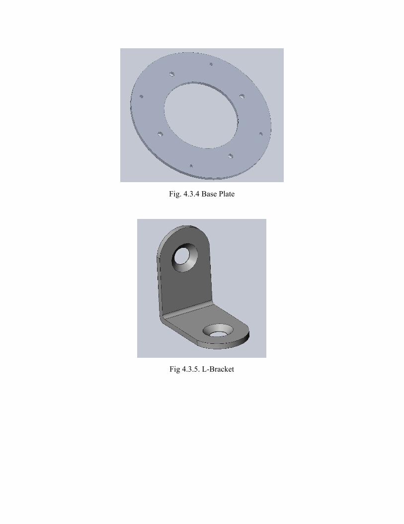
Fig. 4.3.4 Base Plate
Fig 4.3.5. L-Bracket

Fig. 4.3.6 Base Plate Bracket Assembly
The base plate is attached to the body tube by 4 25x25mm stainless steel L-Brackets. These
L-brackets are affixed to the base plate by screws and the sides of the main body tube by screws.
The 4 brackets assure that the forces will be evenly spread out along the body of the rocket and
the base plate. In Fig. X it is shown that the rocket is able to easily withstand the forces that will
be presented on it. L-brackets were used because they provide easy access to the inside of the
rocket by simply removing 4 easily accessible screws at the bottom of the base plate. The
L-Brackets are mounted to the sides of the body tube around 7mm up from the bottom of the
tube. This is done with screws and hex nuts on the inside of the body tube as well as on the
actual base plate. All the holes are fitted and placed exactly so the brackets and servo mounts lie
flush with the body tube of the rocket.
The base plate is water jetted for perfect hole sizes and locations to ensure that the servos can be
mounted properly in place as well as the brackets. The staggering of the holes allows for plenty
of space between the servos and the brackets as well as keeping the weight distribution exactly
even within the rocket. The water jetting of the base plate allows for perfect dimensions for the
motor assembly to fit into.

4.4 Precision and Repeatability
The system can be confidently predicted as consistent because the microcontroller sends
a consistent signal to each servo, and each servo is both electrically and mechanically linked to
each other, so they always rotate to the same angle. Electrically, if one servo is shown to fail or
not be moving, all servos will hold their position to prevent the rocket from spinning out of
control. Mechanically, the attached to each servo shaft is a bevelled gear that interfaces to one
large gear. This forces each servo to always actuate to the same angular position, and if a motor
fails the gear will still be turned by the other 3 motors, and the system will perform the same.
4.5 Performance Predictions
The team has planned the roll system to induce slightly over 2 full rolls post burnout.
After doing this, gyroscopes will detect the current angular velocity and induce a counter roll to
bring the rocket back to its initial angular velocity. This will be done using a closed loop
autonomous program to induce the correct angle given current position and angular velocity, and
initially will be controlled with a hard coded roll system in order to choose between our possible
final configurations for the final launch . We have primarily used OpenRocket and simple
calculations to determine this initial hard coded roll. The calculations are listed below:
The Lift Coefficient for a flat plate is approximately where alpha is in radians,πα2
l≈2παC
Below is the equation for lift:
Cl ·ρ·v ·A·.5L = 2
2πα ·ρ·v ·A·.5L = 2
≈ ·10ρavg 22.2743+2.0174 −3
.843188 in 0127999 f tA = 1 2 = . 2

2πα · 2.14585× 10 ·v ·.0127999·.5L = −3 2
8.62891866428× 10 ·αvL = −5 2
287.9031 f t/secvavgork =
7.153741·αL =
Assuming the rocket can be simplified as a disc, we then substitute into the following
equation to see how angular velocity relates to the torque on the rocket:
5Iω θ. 2 = τ
5Iω t. 2 = τ 2ω
1.73965tα·4ω = t·τ.5MR2 = 7
1.73965tα·4tθ = 7
1.73965t α·4θ = 7 2
π 1.73965t α·44 = 7 2
Angle of Attack for the fin was predetermined at 5 degrees or .0872665 rad
π
.0872665 71.73...*= t2
.708 secst =
This calculation for 2 spins is further corroborated by the OpenRocket Program which
gives 3.2337 rolls in .71 seconds when starting with the flaps at an initial angle of attack of 5
degrees. According to our OpenRocket simulations,this will occur approximately 11 seconds into
flight.

5. Electrical Subsystem
5.1 Flight Systems Overview
As stated previously, the development guide for the Pixhawk is still in its beta stages and lacks
the resources to complete such a project in a timely manner. The Pixhawk will no longer be responsible
for actuating the servo motors of the vehicle, but instead, an MBED ARM microcontroller will take its
place. The only external connections made to the Pixhawk will include a reset switch, power
source, air speed sensor, the eggfinder GPS receiver, and four servo controllers located at the
bottom of the rocket. Simply put, our flight systems consists of the Pixhawk, the recovery
system, and the Servo Actuation System, which comprised of MBED and HS-5085 servo motors.
Figure 5.1.1 below includes the performance specifications of the HS-5085 Premium Metal Gear
Micro Servo in the Servo Actuation System, and Figure 5.1.2 includes the specifications of the
Eggfinder GPS system.
Figure 5.1.1 HS-5085 Servo Specifications

Figure 5.1.2 Eggfinder TX GPS Module Specifications
5.2 Flight System Features
The electrical subsystem onboard the flight vehicle has several purposes including:
deployment of parachutes, acquisition of data for post-flight analysis, and control of the flaps in
order to reach the desired apogee of one mile. Data acquisition and parachute deployment are
accomplished by the altimeter solely, but control of the rocket flaps calls for a more elaborate
flight software, a microcontroller flight computer, and the use of an added sensor: the
accelerometer. Both the altimeter and the accelerometer output sensed values into an Mbed
microcontroller, which then filters noise from the sensors according to the kalman filter
specifications. The filtered values are then compared to flight simulation data generated via
Simulink, and the control algorithm makes the difference between sensed and simulation values
go to zero as time gets larger. The control algorithm works based on an equation, shown in
Figure XX, that relates the change in height to the change in velocity.
Figure XX. The equation that describes control of the rocket.
5.2.1 Launch Vehicle
The avionics system is comprised of three primary components: a Pixhawk flight
controller, an mbed microcontroller, and an array of servos.

The integrated IMU (Inertial Measurement Unit) of the Pixhawk is used to gather angular
velocity, acceleration data. An airspeed sensor and Eggfinder GPS provide the Pixhawk with
airspeed and location data. This data is then transferred from the Pixhawk to the mbed via serial
from the Pixhawk’s UART port to the serial pins on the mbed. The mbed then uses this
information to actuate the 4 servos linked to the fins and induce a roll and counter-roll. The
Pixhawk is set up with a triple redundant power supply. Utilizing the Pixhawk allows for a more
compact and simpler wiring scheme, easy calibration of sensors, and an all-around more robust
system.
Power, ground, and PWM signal must be transferred from the avionics bay roughly 55
inches down the fuselage to the servos mounted near the base of the rocket. This is accomplished
using a single braided cable. Two female servo plugs joined by a three pin header fasten the
servo leads at the junction between the avionics bay and lower-most fuselage section. This
configuration ensures smooth detachment of the servo connections during separation. At the base
of the rocket, this cable interfaces with a breakout board that distributes power, ground, and
signal to all four servos. The use of a single cable and breakout board simplifies the wiring
scheme, allows for easy assembly and disassembly (each servo, as well as the central cable, can
be unplugged from the power distribution board) and reduces the number of wires that must be
severed at separation from 12 to 3.
The avionics system is powered by a two amp hour, three cell, 11.1 volt, lithium polymer
battery. This capacity was chosen to ensure that the vehicle can remain on standby for a
minimum of one hour. The voltage is reduced to the 5 volts needed to operate the servos,
Pixhawk, and mbed using step down regulator mounted on a protoboard. An addition one amp
hour battery and 5 volt regulator are also present to provide redundancy in the event that a
battery or regulator fails. Also, on this protoboard are headers to supply the Pixhawk and mbed
with power, headers to supply the servo cable with power, ground, and signal (from the mbed),
and circuitry that supports two switches on the exterior of the fuselage.
The avionics system has only three components visible from the exterior of the rocket: a
key switch to turn on power to the system, an arming switch for the Pixhawk, and a SPDT
(Single Pole Double Throw) switch that turns on the mbed as the vehicle leaves the launch rail.

The arming switch interfaces directly with the Pixhawk. Both the key switch and the SPDT
switch interface with the protoboard housed in the avionics bay. The SPDT switch is required
because the code running on the mbed requires the microcontroller to boot up only once the
rocket has taken to the air. While on the pad, the SPDT switch remains depressed against the
guide rail, depriving the mbed of power. As soon as the rocket clears the rail, the switch closes
the circuit with the mbed, the mbed boots up, and its code is executed.
5.2.2 Roll Control
5.2.2.1 Overview: Roll Description
The roll maneuver of the rocket will occur between the time that burnout occurs and the
time that the rocket reaches its apogee. The roll will consist of at least two 360 degree turns, and
then the rocket will experience a counter-moment in order to stop rolling. It will then roll back to
its initial angular speed prior to the motor burnout. The rolls and counter-rolls will be induced
when the ailerons on the fins are angled a predetermined amount; this amount will be determined
after testing and analysis.
5.2.2.2 Roll System: Explanations and Alternatives
The main issues with our chosen design were determining at which angle to actuate the
fin, determining the area of the flap, figuring out how long the fin should be actuated, and seeing
if the servos themselves could handle the force on the fins. Using a predetermined angle of 5
degrees and a predetermined area of the flap, testing allowed the team to see if the chosen servo
could handle the drag force. Testing also enabled the team to determine the length of time for
which the fins need to be actuated. The calculations are listed below (Units used in the
calculation below are ft, sec, and radians):

The Lift Coefficient for a flat plate is approximately where alpha is in radians,πα2
l≈2παC
Below is the equation for lift:
Cl ·ρ·v ·A·.5L = 2
2πα ·ρ·v ·A·.5L = 2
≈ ·10ρavg 22.2743+2.0174 −3
.843188 in 0127999 f tA = 1 2 = . 2
2πα · 2.14585× 10 ·v ·.0127999·.5L = −3 2
8.62891866428× 10 ·αvL = −5 2
287.9031 f t/secvavgork =
7.153741·αL =
Assuming the rocket can be simplified as a disc, we then substitute into the following
equation to see how angular velocity relates to the torque on the rocket:
5Iω θ. 2 = τ
5Iω t. 2 = τ 2ω
1.73965tα·4ω = t·τ.5MR2 = 7
1.73965tα·4tθ = 7
1.73965t α·4θ = 7 2
π 1.73965t α·44 = 7 2
Angle of Attack for the fin was predetermined at 5 degrees or .0872665 rad
π
.0872665 71.73...*= t2
.708 secst =

This calculation for 2 spins is further corroborated by the OpenRocket Program which
gives 3.2337 rolls in .71 seconds when starting with the flaps at an initial angle of attack of 5
degrees. Team ARES’s rocket will as such have four fins, each with a movable flap at the rear, to
initiate rolls. Given the calculations, the flaps will be deployed for .71 seconds at an angle of 5
degrees to roll at least 2 times. The torque experienced by each individual servo, approximately
30 oz-in, is also well below the 59.7 oz-in max that each servo can handle. This torque was
derived from the OpenRocket rotational velocity and the calculations above. In order to perform
the counter-roll, the rocket will reverse the direction of the fins until the roll of the rocket
matches the final roll of the rocket post motor-burnout. The HS-5085MG Servo will be used,
which should be adequate based on the calculations for the necessary torque to directly drive the
flap attached to the shaft.
The two main alternatives considered when initially designing the roll system were
including a pneumatic system or inserting a flywheel. The pneumatic system would have
released pressurized gas out of the rocket in order to induce a spin, but the team decided against
it due to the amount of possible errors, additional weight, and safety issues of the complicated
system. The flywheel was not chosen because the flywheels that were available to the team for
purchase were either built for much larger craft or were too massive for use.
Calculations for Flywheel:
3.134337) (720 deg/s) (1/2) Mass of F lywheel) radius ) ω( * 2 = * ( * ( 2 * 2
f lywheel ω = √ (3.134337 720 )* 2
(.5 2kg 5cm 5cm)* * *
f lywheel deg/s ω = √ (.5 2 .05 .05)* * *(3.134337 720 )* 2
25493.8 deg/s 70 0 4200 rpmω = = * 6 =

As seen in the calculations above, a 2 Kg. mass flywheel would be necessary to generate
enough moment at a low enough rpm that the motor would be able to accelerate in both
directions in the short duration of the remaining flight time after motor burnout. This mass would
account for nearly 40% of the rocket mass, which is not feasible, especially because this could
introduce gyroscopic precession into the system if the rocket is not perfectly vertical at all times.
Additionally, there was not much data available for flywheel use in hobby sized craft and rough
calculations suggested that a flywheel would not be able to accelerate in one direction and then
reverse directions fast enough to meet the post motor burnout requirements.
5.2.2.3 Roll Dimensional Drawings and Component Description
The roll system consists of four fins, four servos, and 4 control surfaces under the four
main fins, which are shown in Figures 5.2.2.1, 5.2.2.2, and 5.2.2.3 below, with dimensions given
in Table 5.2.4.1. The servo that will be used for this project is the HS-5085MG Servo; it has 60
oz.-in. of torque and requires 4.8-6.0 volts for operation. The servos will be directly modulating a
control surface next to the main fins. This control surface will redirect the flow of air in order to
generate a moment about the center axis of the rocket. The servos will be modulated in real time
using a programmable Pixhawk devboard. This system will monitor the gyroscopic and
acceleration sensors in order to determine motor burnout and roll rate, and it will in turn allow
for the rocket to achieve two rotations and stabilization. The control surfaces be attached to a rod
in front of the surface, and this rod will be directly driven by the servo motor. The rod will be
secured by installing it through rings extending from the fin above the control surface. This is
done to ensure the control surface will be stable, while preventing any excessive moments on the
servo. The servo will be secured to the inner tube and centering rings of the rocket by a 3D
printed housing, allowing easy access by sliding out the inner tube from the rocket.

Figure 5.2.2.1 - Rocket Fin & Flap Mechanism
Figure 5.2.2.2 - Hinge Mechanism

Figure 5.2.2.3 Hinge Assembly
Figure 5.2.2.4 Fin Bracket (left), Rotating Flap Bracket (right)

5.2.2.4 Design Meets All Requirements with Acceptable Risk Levels
The launch vehicle is to be outfitted with 4 adjustable fins attached to the end of 4
stationary fins. The main purpose of these is to induce a roll in the launch vehicle. However, this
presents a pressing issue that the failure of this mechanism would result in a catastrophic crash.
Therefore it is imperative that the design be designed with enough safeguards such that when the
launch vehicle is subject to aerodynamic loads on the variable fins, all fins shall maintain the
same orientation. This will be accomplished with large gear ring that will constrain all the
variable fins to the same orientation. The design will solve the issue of a single servo failure,
effectively adding parity to the design.
The fins will be manufactured from fiberglass and the hinge mechanism will be
constructed from a high strength steel. This will prevent fractures in the variable fin assembly. In
order to prevent slip of the rotating fin on the drive shaft, the shaft will be machined into a square
shape. This design will ensure that force transfer is efficient and there will be reduced risk of fin
slip on the shaft. Additionally, the drive shaft will place its weight on the rocket frame thereby
removing direct stresses applied to the servo motor directly. This will reduce the likeliness for
failure due to servo motor burnout.
The failure mode of this assembly has now been limited to failures that would be
catastrophic, but impossible to prevent without using significantly more expensive materials or
weight. Therefore, the risk in this design has been minimized to as low as possible given the
budget, manufacturing, and rule constraints.
5.2.2.5 Fin Shape and Style
The fins were designed and tested in OpenRocket software at the beginning of the
semester; once an OpenRocket model of the entire rocket was created, differently shaped fins
were added to the model and tested using the software’s test flight simulator. After assessing all
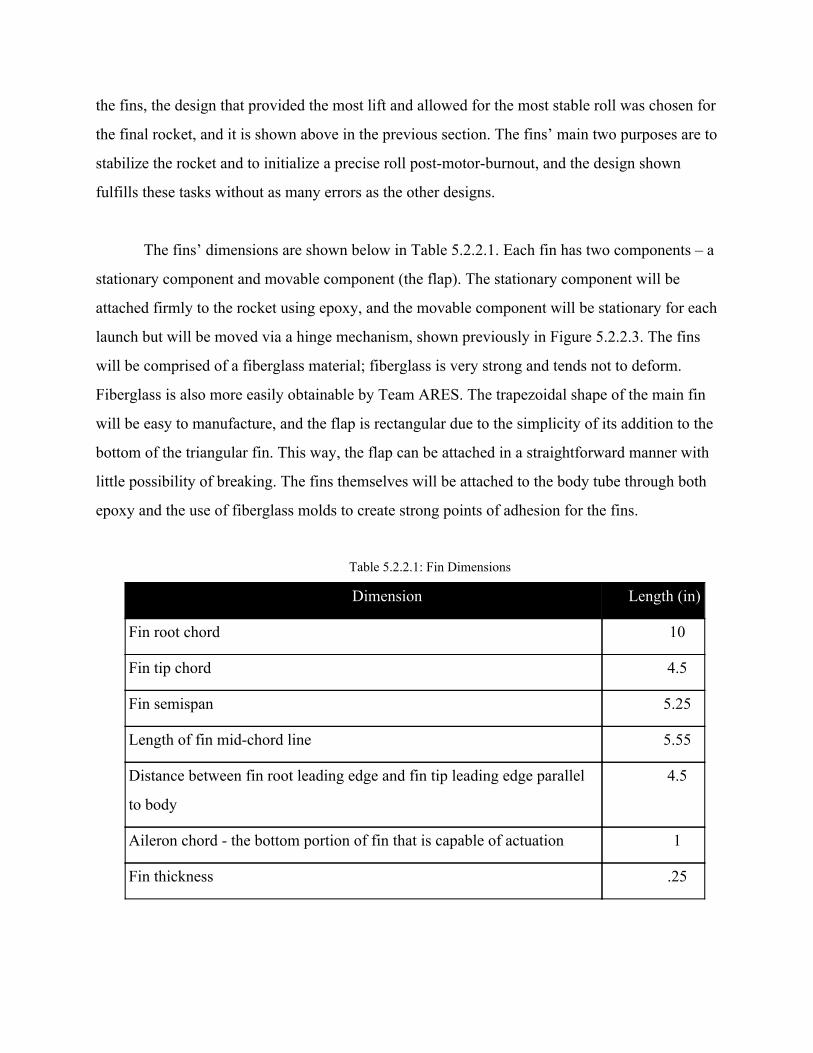
the fins, the design that provided the most lift and allowed for the most stable roll was chosen for
the final rocket, and it is shown above in the previous section. The fins’ main two purposes are to
stabilize the rocket and to initialize a precise roll post-motor-burnout, and the design shown
fulfills these tasks without as many errors as the other designs.
The fins’ dimensions are shown below in Table 5.2.2.1. Each fin has two components – a
stationary component and movable component (the flap). The stationary component will be
attached firmly to the rocket using epoxy, and the movable component will be stationary for each
launch but will be moved via a hinge mechanism, shown previously in Figure 5.2.2.3. The fins
will be comprised of a fiberglass material; fiberglass is very strong and tends not to deform.
Fiberglass is also more easily obtainable by Team ARES. The trapezoidal shape of the main fin
will be easy to manufacture, and the flap is rectangular due to the simplicity of its addition to the
bottom of the triangular fin. This way, the flap can be attached in a straightforward manner with
little possibility of breaking. The fins themselves will be attached to the body tube through both
epoxy and the use of fiberglass molds to create strong points of adhesion for the fins.
Table 5.2.2.1: Fin Dimensions
Dimension Length (in)
Fin root chord 10
Fin tip chord 4.5
Fin semispan 5.25
Length of fin mid-chord line 5.55
Distance between fin root leading edge and fin tip leading edge parallel
to body
4.5
Aileron chord - the bottom portion of fin that is capable of actuation 1
Fin thickness .25

Figure 5.2.2.5 - System on Rocket
All of these components will either be purchased online, or manufactured from bulk
material using our campus machine shops. Table 3.2.3 provides additional details on this topic.
Table 5.2.2.2. Component Breakdown
Component Material Manufacturing Method
Small Gears 6061 T6 Aluminum N/A → Purchased
Large Ring Gear 6061 T6 Aluminum Waterjet
Fin G10 Fiberglass Waterjet + Mill
Rotary Flap G10 Fiberglass Waterjet + Mill
Hinges 6061 T6 Aluminum Waterjet
Square Shaft Carbon Steel N/A → purchased
Shaft-Servo
Interface ABS Plastic 3D printed

5.3 Flight Systems Software
The software component of the rocket operates in three primary stages: data collection, data
transfer, and response. Location of the rocket in latitude and longitude is collected by the GPS; this data is
then sent to the Pixhawk. Airspeed is recorded by an airspeed sensor, which is also sent to the Pixhawk.
The Pixhawk itself takes in the angular velocity of the rocket, as well as the acceleration and altitude. The
Pixhawk stores all of this data collectively, which can be analyzed after flight. This completes the data
collection stage of the software component. After the following data is collected, it is compiled and sent
to the MBED Microcontroller. The MBED compares this data that of previous launches and based on
certain criteria determines if the fins should be adjusted. If an adjustment is necessary, the MBED
activates the 4 servos to respond. The following diagram Figure 5.3.1 shows a schematic of the flight
software and the data flow.
Figure 5.3.1 Flight System Software Flow of Data

5.4 Recovery System Electronics
The recovery system has not changed since the preliminary design review. The primary
component of the rocket’s recovery system, the Perfectflite StratloggerCF altimeter, is capable of
measuring altitude through the use of a barometric pressure sensor. The StratoLogger altimeter
additionally has the ability to deploy parachutes by ejecting a large output current at the desired
height. Two of these will act as the sole electrical components of the recovery system. They will
both be powered independently and connected to both the main and drogue chutes in order to
ensure dual redundant chute employment. Additionally, one altimeter is set to blow its charges
at a delay of one second. As seen in figure 5.4.1, the StratoLogger CF is an industry standard
model rocketry altimeter. Through its robust and easily modifiable design, it provides a desired
reliability for the recovery system of the rocket.. The stratologger altimeter was carefully
selected in order to ensure successful recovery: the subscale launch confirmed that it can be both
trustworthy and reliable.
Figure 5.4.1: The StratologgerCF altimeters with connection labels (for reference)

6. Safety
6.1 Overview: Personnel Hazard Analysis
The following table entails the information on the general risks that the team may
experience while constructing the rocket. The table goes through the severity, likelihood, and
prevention methods for each hazard.
Table 6.1.1. Safety Risks
Hazard Severity Likelihood Mitigation & Control
Batteries
Explode
Burns, skin and
eye irritation
Low Wear safety glasses and gloves when
handling. Make sure no shorts exist in
circuits using batteries. If battery gets
too hot, stop its use and disconnect it
from any circuits.
Fiberglass irritate the eyes, skin
and upper respiratory
tract
High Gloves, particulate masks, safety
glasses, and the proper clothing will be
worn. Work in well ventilated areas
and wash hands thoroughly after. Hold
vacuum over any open machining
process.
Black Powder Explosions, burns,
skin and eye
irritation
Medium Wear safety glasses, gloves when
handling black powder. Be careful
when pouring black powder. Operate
in a static-free environment.

Dremel Cuts and scrapes Medium Only operate tools with supervision of
teammates. Use tools in appropriate
manner. Wear safety glasses to prevent
debris from getting into eyes.
Power Tools Cuts, punctures,
and scrapes
Medium Only operate power tools with
supervision of teammates. Use tools in
appropriate manner. Wear safety
glasses to prevent debris from getting
into eyes.
Epoxy/Glue Toxic fumes, skin
and eye irritation
High Wear gloves, nitrile for epoxy, face
masks, and safety glasses. Work in
well ventilated area.
Exacto/Craft
Knives
Cuts, serious/fatal
injury
Medium Only use knives with teammate
supervision. Only use tools in
appropriate manner. Do not cut in the
direction towards oneself.
Fire Burns,
serious/fatal injury
Low Keep a fire extinguisher nearby. If an
object becomes too hot, or does start a
fire, remove power (if applicable) and
be prepared to use the fire
extinguisher.
Hammers Bruises,
serious/fatal injury
Medium Be aware of where you are swinging
the hammer, so that it does not hit
yourself, others, or could bounce and
hit someone.

Hand Saws Cuts, serious/fatal
injury
Medium Only use saws with teammate
supervision. Only use tools in
appropriate manner. Wear safety
glasses to prevent debris from getting
in eyes.
Sanding Irritation of skin,
dust particles
Low Only use sander while wearing safety
glasses and mask
Waterjet Cutter Cuts, serious/fatal
injury, flying
debris
Low Only operate under supervision of
Undergraduate/Graduate Learning
Instructors or PI in the Invention
Studio, and with other teammates.
Follow proper operating procedures,
wear safety glasses.
Laser Cutter Serious burns, eye
damage
Low Be sure to use proper materials when
laser cutting and wear safety goggles
Improper dress
during
construction
Cuts, serious/fatal
injury
High Wear closed toed shoes, tie back long
hair, do not wear baggy clothing.
Power Supply Electrocution,
serious/fatal injury
Medium Only operate power supply with
teammate supervision. Turn off power
supply when working with circuitry.
6.2 Failure Modes and Effects Analysis

The following table entails the potential failure modes that may be experienced by the
Launch Vehicle team and the prevention method for each failure mode.
Table 6.2.2. Failure Mode
Potential Failure Effects of Failure Mitigation and Control
Body structure
buckling on takeoff
Launch failure, damage to
launch vehicle, unable to be
reused, flying shrapnel
towards personnel/crown
Test structure to withstand expected
forces at launch with a factor of
safety. Have proper sized couplers
connecting sections.
Drogue separation Main parachute will deploy
at high speed and may rip or
disconnect from vehicle,
launch vehicle may become
ballistic
Perform ground test and flight test to
ensure drogue separation
Fins Fins could fall off, causing
unstable flight.
Fins break or disconnect
from launch vehicle, unable
to be classified as reusable
Test fin at attachment points using
expected forces to ensure strength of
attachment method.
Do not have fins with sharp pointed
edges, ensure parachute is large
enough to minimize impact kinetic
energy, test fin at attachment points
using expected forces to ensure
strength of attachment.
Ignition failure Failure to launch Follow proper procedures when
attaching igniter
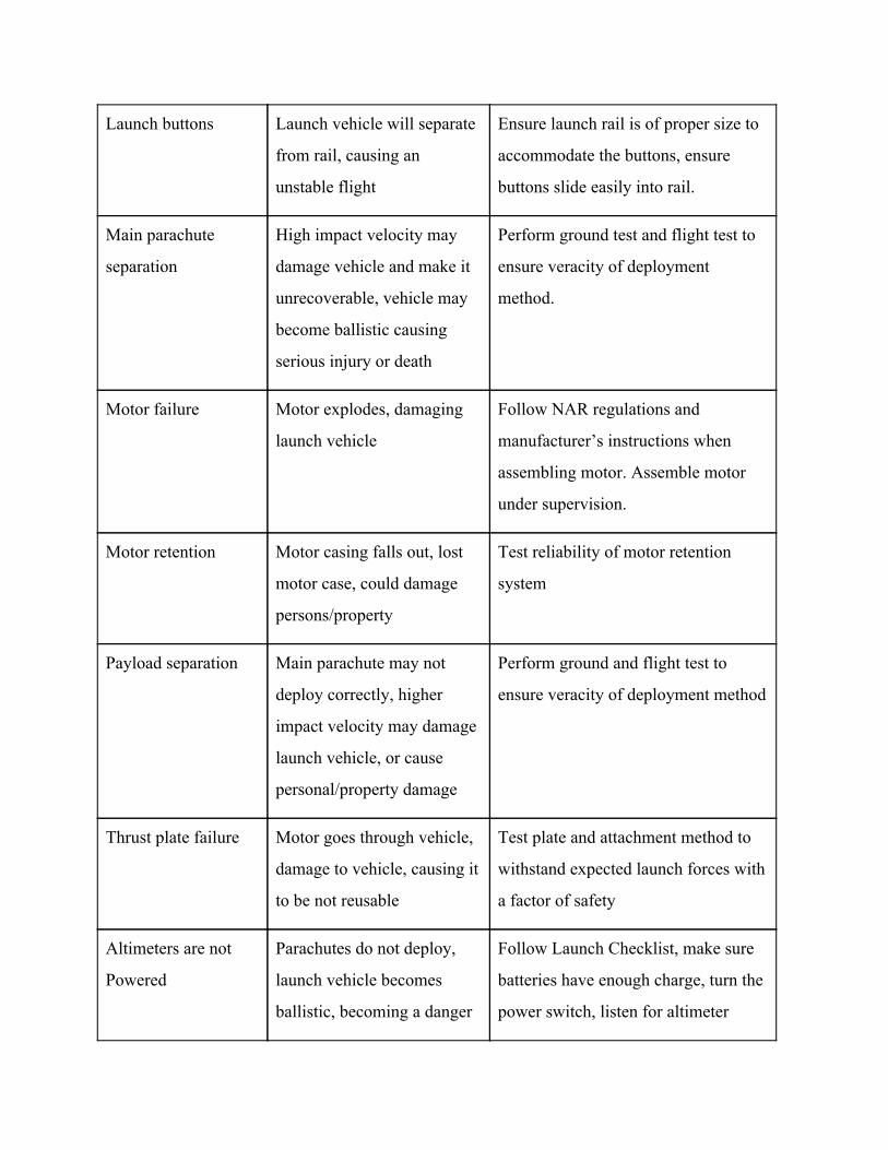
Launch buttons Launch vehicle will separate
from rail, causing an
unstable flight
Ensure launch rail is of proper size to
accommodate the buttons, ensure
buttons slide easily into rail.
Main parachute
separation
High impact velocity may
damage vehicle and make it
unrecoverable, vehicle may
become ballistic causing
serious injury or death
Perform ground test and flight test to
ensure veracity of deployment
method.
Motor failure Motor explodes, damaging
launch vehicle
Follow NAR regulations and
manufacturer’s instructions when
assembling motor. Assemble motor
under supervision.
Motor retention Motor casing falls out, lost
motor case, could damage
persons/property
Test reliability of motor retention
system
Payload separation Main parachute may not
deploy correctly, higher
impact velocity may damage
launch vehicle, or cause
personal/property damage
Perform ground and flight test to
ensure veracity of deployment method
Thrust plate failure Motor goes through vehicle,
damage to vehicle, causing it
to be not reusable
Test plate and attachment method to
withstand expected launch forces with
a factor of safety
Altimeters are not
Powered
Parachutes do not deploy,
launch vehicle becomes
ballistic, becoming a danger
Follow Launch Checklist, make sure
batteries have enough charge, turn the
power switch, listen for altimeter

to people and property beeps when switches are activated.
Altimeter Switch
wires break
Altimeters will not arm Provide for space within the avionics
bay so that the other electronics and
structures will not pull or apply force
to the wires.
Ejection charges do
not detonate
Parachutes do not deploy,
rocket becomes ballistic,
payload does not deploy
Test connections of the terminal
blocks with wires shorting the
connections, listen for the right
number of beeps from the altimeter
Flame retardant cloth
is not attached to
shock cords
Parachutes and Shock Cords
may become burned and do
not decelerate the rocket
sufficiently, the rocket will
have too much kinetic
energy, causing the rocket to
break on impact, and become
a danger to people and
property
Follow Launch Checklist, attach the
cloth to shock cord before parachute is
inserted into appropriate bay.
Parachute shock
cords are not
connected to the
tethered sections
Sections of the rocket will
become detached without
parachutes, becoming a
danger to people and
property
Follow Launch Checklist, ensure
shock cords are connected to each
tethered section using appropriate
knots
Failure to separate Inevitable deployment
failures with ballistic descent
and guaranteed severe
Sand the coupler extensively to assure
a smooth separation and pay close
attention to separation during testing

structural damages due to
high velocity impact with an
additional risk of injury
High descent speed Likely structural damages
due to high velocity impact
Drogue parachute sizing calculations
Low descent speed Likely loss of launch vehicle
due to cross range
displacement and rocket may
land in unauthorized areas
Use of a properly sized parachute and
careful timing of drogue parachute
deployment
Parachute ignition Avionics bay or payload may
also be set on fire
Will use “dog barf” to insulate
Parachute rupture or
entanglement
Likely structural damages
due to high velocity impact
Will ensure that parachute is properly
folded and packed
Premature,
unintended
deployment
If mid-flight, rocket may
de-stabilize the structural
integrity of parachutes is in
peril
Key switch and electronics
regulations; off until rocket is on
launchpad
6.3 Mitigation List
The following table entails potential failures that were experienced by the Launch
Vehicle team and the mitigation for each failure mode.

Table 6.3.3. Failure Mode
Place of Failure Failure Cause Solution
ATS
Tube could buckle
during flight or
landing
Cut-outs for flaps
would structurally
weaken tube Removed ATS
Parachute
deployment
Both main and
drogue parachutes
were prone to getting
caught on shear pins
during deployment
Shear pins were in the
coupler that joined
avionics bay to
adjacent sections. The
parachutes lie in these
couplers
Placed avionics bay into a
coupler rather than tube,
and placed shear pins
inside avionics bay, so
they would never interact
with parachutes
Fasteners
Risk of having nuts
and screws shake
loose
Intense vibrations
during ascent
Minimize fasteners, and
use locktite where possible
Battery Fastening
Batteries could be
forced out of their
method of
securement and
disconnect
mid-flight
High acceleration
during launch could
break form of
securement as it did in
subscale (zipties)
Use actual battery holders
designed for high stress
applications. Screw down
battery mounts to the
avionics tray.
Servo failure in roll
control Mechanism
A servo failure, or
misalignment could
cause one of the
flaps to not rotate
equally, thus
inducing a moment
on the rocket that
A servo could burn out
or become misaligned
with regards to the
other servos. Its
connection to the
pixhawk in the
avionics bay could
All servos are
mechanically joined with a
single large gear that is
connected to the small
gears riding on each shaft
to ensure all the shafts are
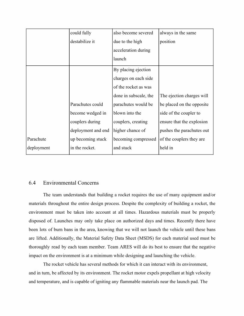
could fully
destabilize it
also become severed
due to the high
acceleration during
launch
always in the same
position
Parachute
deployment
Parachutes could
become wedged in
couplers during
deployment and end
up becoming stuck
in the rocket.
By placing ejection
charges on each side
of the rocket as was
done in subscale, the
parachutes would be
blown into the
couplers, creating
higher chance of
becoming compressed
and stuck
The ejection charges will
be placed on the opposite
side of the coupler to
ensure that the explosion
pushes the parachutes out
of the couplers they are
held in
6.4 Environmental Concerns
The team understands that building a rocket requires the use of many equipment and/or
materials throughout the entire design process. Despite the complexity of building a rocket, the
environment must be taken into account at all times. Hazardous materials must be properly
disposed of. Launches may only take place on authorized days and times. Recently there have
been lots of burn bans in the area, knowing that we will not launch the vehicle until these bans
are lifted. Additionally, the Material Safety Data Sheet (MSDS) for each material used must be
thoroughly read by each team member. Team ARES will do its best to ensure that the negative
impact on the environment is at a minimum while designing and launching the vehicle.
The rocket vehicle has several methods for which it can interact with its environment,
and in turn, be affected by its environment. The rocket motor expels propellant at high velocity
and temperature, and is capable of igniting any flammable materials near the launch pad. The

vehicle motor could explode, causing shrapnel to fly at people and property, and could cause a
fire. After launch, the rocket accelerates upward and becomes a hazard to flying machines and
animals, so the rocket will not be launched in the presence of birds or airplanes/helicopters in the
immediate launch vicinity. Excessive windy conditions Clouds in the launch vicinity may
obscure the launch vehicle as it climbs to apogee, which could make the vehicle a ballistic threat
to people and property if the parachutes do not deploy.
6.5 Launch Procedures
Table 6.5.1 Launch Preparation
Prepare Payload Recovery System
Ensure batteries and switches are wired correctly
Ensure batteries, power supply, switches, microprocessor, GPS,
pixhawk is/are wired correctly
Install and secure fresh batteries into battery holders
Insert payload recovery electronics into payload recovery bay
Connect appropriate wires
Arm altimeter with output shorted to verify jumper settings. This is
done to verify battery power and continuity
Disarm Altimeter, un-short outputs
Prepare Body Recovery System
Ensure batteries and switches are wired correctly

Ensure batteries, power supply, switches, microprocessor, GPS,
pixhawk is/are wired correctly
Install and secure fresh batteries into battery holders
Insert body recovery electronics into payload recovery bay
Connect appropriate wires
Arm altimeter with output shorted to verify jumper settings. This is
done to verify battery power and continuity
Disarm Altimeter, un-short outputs
Assemble Charges
Test e-match resistance to see if it is within specifications
Remove protective cover from e-match
Measure amount of black powder used in testing
Place e-match on tape with sticky side up
Pour black powder over e-match
Seal Tape
Re-test e-match
Check Altimeters
Ensure altimeters are disarmed
Connect charges to ejection wells
Turn on altimeters to verify continuity

Disarm altimeters
Pack Parachutes
Connect drogue shock cord to booster section and body section
Attach drogue parachute to drogue shock cord
Pack drogue parachute
Fold excess shock cord so it does not tangle
Attach Nomex cloth to shock cord so it will enclose and shield the
parachute while exposing only the Kevlar shock cord to ejection
charge
Insert cellulose wadding into drogue parachute bay between ejection
charges and parachute
Insert drogue parachute and shock cord into drogue parachute bay
Insert booster section into lower body section, and secure with shear
pins
Attach main parachute shock cord to upper body section and lower
payload parachute bay
Attach main parachute to main parachute shock cord
Pack main parachute
Fold excess shock cord so it does not tangle
Attach Nomex cloth to shock cord so it will enclose and shield the
parachute while exposing only the Kevlar shock cord to ejection
charge

Insert cellulose wadding into main parachute bay between ejection
charges and parachute
Insert main parachute and shock cord into main parachute bay and
Insert upper body section into the lower section of the payload
parachute bay, and secure with shear pins
Attach payload parachute shock cord to payload section
Attach parachute to the end of the payload parachute shock cord
Pack payload section parachute
Fold excess shock cord so it does not tangle
Attach Nomex cloth to shock cord so it will enclose and shield the
parachute while exposing only the Kevlar shock cord to ejection
charge
Insert cellulose wadding into upper payload parachute bay between
ejection charges and parachute
Insert drogue parachute and shock cord into upper payload parachute
bay
Insert payload section into payload parachute bay and secure with
shear pins
Assemble motor
Follow manufacturer’s instructions
Do not get grease on propellant grains or delay grain
Do not install igniter

Install Motor in launch vehicle
Secure motor retention system
Launch Vehicle Prep
Inspect launch vehicle, check CG and make sure it is within specified
range
Bring launch vehicle to Range Safety Officer(RSO) for inspection
Touch igniter clips together to make sure they will not fire the igniter
when connected
Connect igniter clips to motor igniter
Launch
Watch flight so launch vehicle sections do not get lost
Post Launch Payload/Vehicle Recovery
Recover Payload Section and tethered Body/Booster Section
Disarm Altimeters if there are unfired charges
Disassemble launch vehicle, clean motor case, other parts, and inspect
for damage
Record altimeter data

6.6 Launch Checklist
PRE-LAUNCH
Checklist Performer Inspector
Pack all necessary equipment/supplies the night
before team leaves for the launch site.
On the morning of departure, check to make sure
all necessary equipment/supplies have been stored
in a secure manner.
LAUNCH
Checklist Performer Inspector
Prepare Payload Bay
Ensure the batteries and switches are properly
connected to the altimeters.
Ensure the batteries, power supply, switches, data
recorders, and pressure sensors are properly wired.
Install and secure new batteries into the battery
holders.
Insert the altimeter into the bay.
Arm the altimeters to verify the jumper settings.
Check the battery voltage and continuity once the
altimeters have been armed.

Disarm the altimeters afterwards.
Assemble Charges
Test e-match resistance and make sure it is within
specifications.
Remove protective cover from e-match.
Measure the required amount of black powder that
was determined during testing.
Place e-match on tape with the sticky side facing
up.
Pour the black powder over the e-match and seal
the tape.
Retest the e-match resistance.
Check Altimeters (Figure 1 for configurations)
Ensure altimeters have been properly disarmed.
Connect charges to the ejection wells/altimeter bay.
Turn on altimeters and verify continuity. Disarm
altimeters afterwards.
ALTIMETER 1
ALTIMETER 2
Pack Parachutes
Connect drogue shock cord to booster section and
altimeter.
Make sure shock cord and parachute have no tears,
burns or frays

Fold excess shock cord so it does not tangle.
Add Nomex cloth to ensure only the Kevlar shock
cord is exposed to ejection charge.
Insert altimeter bay into drogue section and secure
with shear pins.
Pack main chute.
Attach main shock cord.
Tug on both ends of the shock cord or recovery
harness. It should be firmly attached.
Assemble Motor
Follow manufacturer’s instruction.
Use the necessary safety equipment needed such as
gloves and safety glasses.
Be careful not to get any grease on propellant or
delay grain.
Do not install the igniter until at launch pad.
Install motor in launch vehicle.
Secure motor retention system.
Final Preparation
Make sure fin flaps are aligned properly
Inspect the launch vehicle. Verify the CG in order
to make sure it is in safe range. Add nose weight in
the MAS if necessary.
Connect shock cord to nose cone, install nose cone,
and secure with shear pins.

Bring launch vehicle to the range safety officer
(RSO) table for inspection.
Bring launch vehicle to pad, install on pad, and
verify that it can move freely.
Install igniter in launch vehicle.
Touch igniter clips together to make sure they will
not fire igniter when connected.
Make sure clips are not shorted to each other or
blast deflector.
Arm altimeters via switches and wait for continuity
check for both.
Launch
Watch flight so launch vehicle sections do not get
lost.
POST-LAUNCH
Checklist Performer Inspector
Recovery
Recover launch vehicle, document landing.
Disarm altimeters if there are any unfired charges.
Disassemble launch vehicle, clean motor case,
other parts, and inspect for damage.
Record altimeter data and download payload data.
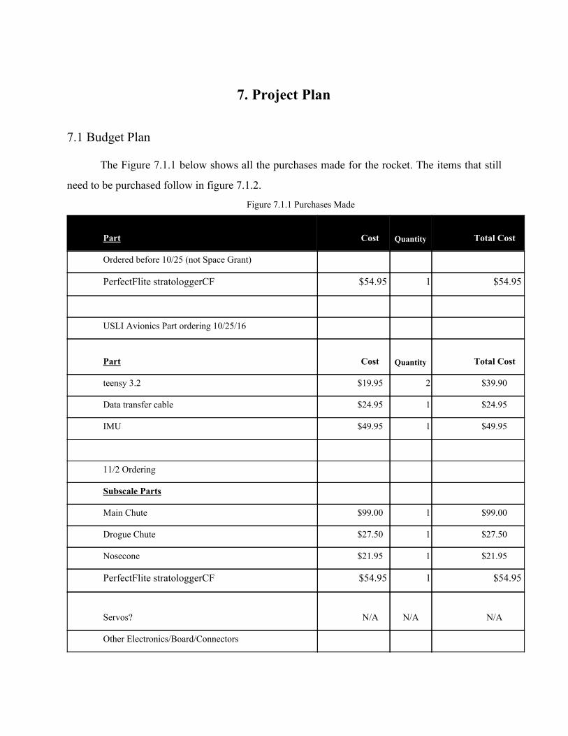
7. Project Plan
7.1 Budget Plan
The Figure 7.1.1 below shows all the purchases made for the rocket. The items that still
need to be purchased follow in figure 7.1.2.
Figure 7.1.1 Purchases Made
Part Cost
Quantity Total Cost
Ordered before 10/25 (not Space Grant)
PerfectFlite stratologgerCF $54.95 1 $54.95
USLI Avionics Part ordering 10/25/16
Part Cost
Quantity Total Cost
teensy 3.2 $19.95 2 $39.90
Data transfer cable $24.95 1 $24.95
IMU $49.95 1 $49.95
11/2 Ordering
Subscale Parts
Main Chute $99.00 1 $99.00
Drogue Chute $27.50 1 $27.50
Nosecone $21.95 1 $21.95
PerfectFlite stratologgerCF $54.95 1 $54.95
Servos? N/A
N/A N/A
Other Electronics/Board/Connectors
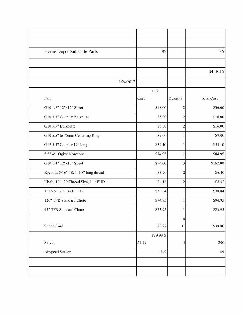
Home Depot Subscale Parts 85 - 85
$458.15
1/24/2017
Part
Unit
Cost
Quantity Total Cost
G10 1/8" 12"x12" Sheet $18.00 2 $36.00
G10 5.5" Coupler Bulkplate $8.00 2 $16.00
G10 5.5" Bulkplate $8.00 2 $16.00
G10 5.5" to 75mm Centering Ring $9.00 1 $9.00
G12 5.5" Coupler 12" long $54.10 1 $54.10
5.5" 4:1 Ogive Nosecone $84.95 1 $84.95
G10 1/4" 12"x12" Sheet $54.00 3 $162.00
Eyebolt: 5/16"-18, 1-1/8" long thread $3.20 2 $6.40
Ubolt: 1/4"-20 Thread Size, 1-1/4" ID $4.16 2 $8.32
1 ft 5.5" G12 Body Tube $38.84 1 $38.84
120" TFR Standard Chute $94.95 1 $94.95
45" TFR Standard Chute $23.95 1 $23.95
Shock Cord $0.97
4
0 $38.80
Servos
$39.99-$
59.99 4 200
Airspeed Sensor $49 1 49

Total = $838.31
2/7
Part Name
Unit
Cost
Quantity Total Cost
APOGEE COMPONENTS
75mm LOC tube $14.95 1 $14.95
Removeable plastic rivet $3.71 2 $7.42
AeroPack 75mm Retainer (Flanged) $53.50 1 $53.50
SERVOCITY
5mm Shaft (250mm) $2.29 4 $9.16
WILDMAN
5.5" G10 Coupler Bulkplate $8.00 3 $24.00
Parachute Protector $10.95 1 $10.95
5.5" G12 Body Tube (5ft length) $194.18 2 $388.36
2/56 Shear Pins $2.95 3 $8.85
Ejection Charges (10 pack) $15.79 2 $31.58
3/8" Tubular Kevlar Shock Cord $2.50
1
2 $30.00
5.5" G12 Coupler (12" length) $54.11 1 $54.11
5.5" G10 Bulkplate $8.00 5 $40.00
5.5" to 75MM centering ring $9.00 4 $36.00
SDPSI
5 mm (HTD) Pitch,22 Teeth, 8mm Bore pulley $13.04 1 $13.04
5 mm (HTD) Pitch, 59 Teeth, 9mm belt $8.27 1 $8.27

Pinion Bevel Gear $13.89 4 $55.56
Bevel Gear $16.58 4 $66.32
MCMASTER-CARR
4 flute, 1/4" end mill (carbide) $21.46 1 $21.46
G10 12"x12" sheet .25" $30.28 1 $30.28
G10 12"x24" sheet .25" $52.68 1 $52.68
2" dia 36" Lg Foam Rod $6.64 1 $6.64
1" x 2" x 1' Al 6063 Bar $34.68 1 $34.68
$997.81
2/5
Gerardo Purchase from CS Rocketry
Payment w/
AE Dept hasn't gone
through yet
L1150R Motor 200 2 400
Motor Casing+Aft/Front Closure 360 1 360
760
Servo Hub (24 tooth splines) $7.99 5 $39.95
5mm Shaft (250mm) $2.29 3 $6.87
Aluminum .25" sheet 6x20" $25.03 1 $25.03
Mask $22.99 1 $22.99
P100 Filter $6.48 1 $6.48
$101.32
Shipping Costs 200 200

Total Spending from Space Grant 2600
Total Spending from AE Department 760
Figure 7.1.2 Items to Be Purchased
Part Name
Unit Cost
Quantity
Total Cost
J380 Motors from Rambling Rocket Club 100 2 200
Eggfinder GPS $50 1 $50
1 night in 4 hotel rooms- competition $330 3
$1,000.00
Gas reimbursement Competition travel $150
$150.00
Rental Car competition $200
$200.00
Total
$1600
Figure 7.1.3 and Table 7.1.1 show the projected total budget for this year’s competition.
Some categories became more costly than anticipated, while others became cheaper. The cost of
the launch vehicle has now been estimated to $3000, larger than the original estimated $2100,
and travel and lodging became more expensive due to the necessity of a rental vehicle. However,
our avionics cost decreased because the Pixhawk controller we use is owned r by our department,
not internally. The expenses we anticipated for outreach also disappeared, because all the events
we are hosting have the materials covered by the participants. For example, the engineering merit
badge we hosted had all materials and food supplied by the troop, and the outreach program

we’re doing with Peachtree Charter Middle school will have the low powered rocket purchases
covered by the school. Our total estimated expenses grew to $5900, which would be concerning;
however, we expanded our funding sources by more than necessary to at least $6900, ensuring
we will not run out of monetary resources.
Table 7.1.1 Projected Budget
Section Cost
Launch Vehicle $3000
Avionics $300
Outreach $0
Travel $1400
Test Flights $1200
Total $5900
Figure 7.1.3 Projected Budget Distribution
7.2 Funding Plan
We are working closely with the Georgia Space Grant Consortium to receive most of the
rocket materials budget as we have done in the past, and they have allocated us $4000, a marked
increase from the $2500 they estimated earlier. The remaining costs will covered through the
Georgia Tech Aerospace Department by alumni and corporate donations, which can allocate

$2500, more than covering all remaining expenses. CCTV Camera World has given us a camera
that will be used to film launches, rocket construction, and outreach events for publicity
purposes. Table 7.2.1 shows our funding sources, which exceeds our cost estimates by 15%,
giving appropriate room for unanticipated costs. The Georgia Tech Ramblin’ Rocket Club has
generously offered the use of some of their tools, storage space, and facilitating the purchase of
rocket motors. Georgia Tech has also provided us a room in the Engineering Science and
Materials Building to use for construction, storage, and meeting space. Orbital ATK also
generously provides a motor and travel stipend.
Table 7.2.1 Planned Sponsors
Sponsor Contribution Date
2015-2016 Unused Funds $388 --
Georgia Space Grant Consortium $4000 Oct 2016
Georgia Tech Aerospace Department $2500 Jan 2017
Orbital ATK Motor and Travel Stipend ? Apr 2017
Total $6888+
7.3 Timeline
7.3.1 Gantt Chart
In order to meet the deadlines given by NASA and the internal deadlines created by
Team ARES, we have created a streamlined Gantt Chart (Figure 6.3.2) to more easily visualize
the timeline of our project milestones, and broke down each task into smaller tasks with
completion dates (Table 6.3.4). This task breakdown contains every step required to achieve our
project milestones and the timing of them to ensure everything is done by deadline. The
breakdown allows us to more easily see if we’re on track to task completion while making it

easier for every team member to understand their assignments and due dates. The figure gives a
streamlined visual layout while the table itself has much more detailed items and dates.

Figure 7.3.1 GANTT Chart
Table 6.3.5 - GANTT Timeline Line Items
Task Start Date End Date
Airframe 10/15/2016 10/20/2016
ATS Design 10
/15/2016
10/17/2016
ATS PDR 10/15/2016 10/20/2016
Recovery Design 10/15/2016 10/17/2016
Recovery PDR 10/15/2016 10/20/2016

Payload Casing Design 10/15/2016 10/17/2016
Payload Casing PDR 10/15/2016 10/20/2016
Flight: CP/CG/Stability 10/15/2016 10/20/2016
Motor + Housing Selection 10/15/2016 10/18/2016
Motor Specs PDR 10/15/2016 10/20/2016
Avionics 9/26/2016 11/13/2016
Order Parts 9/26/2016 10/2/2016
Prototype recovery system 10/3/2016 10/9/2016
Sensor Testing 10/10/2016 10/16/2016
Avionics bay design 10/17/2016 10/23/2016
Prototyping 10/17/2016 10/30/2016
Control script 10/24/2016 10/30/2016
finalize subscale system 10/31/2016 11/13/2016
Operations 10/7/2016 10/30/2016
Assign PDR sections 10/7/2016 10/14/2016
PDR rough draft 10/15/2016 10/21/2016
PDR final draft 10/23/2016 10/30/2016
Subscale Rocket 10/16/2016 1/14/2017
Design 10/16/2016 11/3/2016
Order Parts 11/4/2016 11/4/2016
Building 11/5/2016 11/14/2016
Launch Window 1 11/15/2016 11/15/2016
Launch Window 2 12/3/2016 12/3/2016
Launch Window 3 12/10/2016 12/10/2016
Launch Window 4 12/11/2016 12/12/2016
Repair and Refitting 1/7/2017 1/13/2017
Final Launch Window 1/14/2017 1/14/2017
CDR 1/13/2017 1/31/2017

Assignment Distribution 12/11/2016 12/11/2016
Outline Creation 12/12/2016 12/12/2016
Design Updates 12/13/2016 1/7/2017
Report Writing 1/2/2017 1/13/2017
Formatting 1/13/2017 1/13/2017
Subscale Launch Results Addition 1/14/2017 1/14/2017
Submission 1/15/2017 1/15/2017
Teleconference 1/17/2017 1/31/2017
FRR 1/14/2017 3/24/2017
Final Design Decisions 1/14/2017 1/28/2017
Finalize CAD and OpenRocket 1/28/2017 2/3/2017
Engineering Merit Badge Clinic 2/04/2017 2/04/2017
Create Document Distribution Spreadsheet 2/15/2017 2/15/2017
Distribute Writing Assignments 2/16/2017 2/16/2017
Order Full Scale Parts 1/21/2017 2/15//2017
Create Load Testing Setups 1/15/2017 2/3/2017
Load Tests 2/3/2017 2/10/2017
Roll Control Motor Skeleton Working 1/20/2017 2/3/2017
Finalize Wind Tunnel Test Setup 2/1/2017 2/20/2017
Wind Tunnel Testing 2/21/2017 2/24/2017
Full Scale Part Manufacturing 2/12/2017 2/23/2017
Full Scale Construction 2/20/2017 3/3//2017
Avionics Bay Construction 2/22/2017 2/26/2017
Booster Section Construction 2/22/2017 2/26/2017
Nosecone/GPS Bay Construction 2/19/2017 2/26/2017
Completed Section Assembly 2/26/2017 3/1/2017
Ejection Charge Testing 3/2/2017 3/2/2017
Avionics Working on Rocket 3/1/2017 3/3/2017

Miscellaneous Rocket Assembly 3/1/2017 3/3/2017
Full Scale Test Launch 3/4/2017 3/4/2017
FRR Section Writing 2/18/2017 2/24/2017
FRR Editing 2/25/2017 3/1/2017
Document Formatting 3/1/2017 3/4/2017
Student Foundation Funding Results 2/20/2017 2/20/2017
Submission 3/6/2017 3/6/2017
Teleconference 3/8/2017 3/24/2017
Secondary Test Launch 3/18/2017 4/1/2017
Launch Readiness Review 4/5/2017 4/7/2017
Competition 4/5/2017 4/8/2017
Post Launch Assessment Review 4/8/2017 4/24/2017
Document Write-up 4/8/2017 4/23/2017
Submission 4/24/2017 4/24/2017
7.4 Educational Engagement Plan and Status
7.4.1 Overview
One of the main goals of the GT A.R.E.S. Team is to reach out to the community in order to
promote the Science, Technology, Engineering, and Math fields and to positively affect anyone
with whom the team interacts. Throughout the school year, the A.R.E.S. Team has taken part in
multiple outreach events, including teaching classes to children and talking to teachers about the
team and about how to teach rocketry. The team plans to visit schools in the Atlanta area, with
the goal of encouraging students there to seek careers in STEM fields.

7.4.2. Engineering Merit Badge
The A.R.E.S. team taught an Engineering Merit Badge to a Boy Scouts Of America Troop,
specifically Troop 433, a local metro-Atlanta troop. The badge was taught at Georgia Tech at an
aerospace facility, and the badge included a presentation that showcased different careers in
engineering and introduced numerous examples of engineers’ methods and mindsets. The team
then took the troop on a tour of campus and the aerospace labs located in multiple buildings. This
has created a large amount of interest in teaching more Engineering Merit Badge classes as well
as other merit badges as well, such as Astronomy, Aviation, and Robotics badges.
7.4.3. Peachtree Charter Middle School
Team A.R.E.S. had a successful afterschool program at Frederick Douglass High School in the
previous year, and when the team attempted to restart the program, they learned that the previous
teacher contact at that school had moved to Peachtree Charter Middle School. The teacher,
Aaron Campbell, was greatly interested in creating a similar program at his new school, so the
team went to PCMS one day and formed a plan to come to PCMS during the school day to help
teach rocketry, physics, and math principles to students.This program will be implemented in
March and April, when the curriculum at the middle school begins to include rocket-related
topics.
7.4.4 Atlanta Science Festival
The Atlanta Science Festival is a yearly event in Atlanta celebrating and promoting STEM in the
community. Team ARES plans on volunteering at the festival, and hosting our own booth to
teach the community about our team and rocketry. This event will be held March 14th-25th.
7.5 Team Derived Requirements

7.6 Verification Plan
Table 7.6.1 - Requirements and Design Features
Requirement Design Feature
Vehicle altimeter will report an apogee altitude of
most nearly 5,280 feet AGL.
Mass Addition System(MAS)
Launch vehicle will be designed to be recoverable
and reusable within the day of initial launch.
Vehicle will be constructed of fiberglass to
resist fractures upon landing. Bullet connectors
will be used on wires spanning multiple sections
to prevent damage to wiring upon separation.
Vehicle will require minimal assembly/disassembly
time and effort
Vehicle will be designed to be assembled from
a series of sections/modules with basic hand
tools.
The vehicle will complete two rolls and then
produce a counter-roll
The roll system will deploy post motor burnout
by actuating flaps on the fins to create
asymmetrical drag and generate roll. Roll rate
and direction controlled by Pixhawk.
The launch vehicle shall have a maximum of four
(4) independent sections.
Three (3) sections include: nosecone, avionics,
and booster
The vehicle will be limited to a single stage, solid
motor propulsion system, delivering an impulse of
no more than 5,120 Newton-seconds.
Design using one L-class motor
The launch vehicle shall stage the deployment of its
recovery devices, where a drogue parachute is
All recovery systems will be dual-redundant to
ensure deployment at a safe altitude

deployed at apogee and a main parachute is
deployed at a much lower altitude.
At landing, the launch vehicle shall have a
maximum kinetic energy of 75 ft-lbf.
Main parachute selected by deriving Kinetic
Energy for heaviest independent section
The recovery system will contain redundant
altimeters, each with their own power supply and
dedicated arming switch located on the exterior of
the rocket airframe
A master key-switch installed at the rear of the
avionics bay to close all circuits simultaneously
Each detachable section of the vehicle and payload
must contain an electronic tracking device and
continue transmission to the ground throughout
flight and landing.
A properly shielded GPS system will transmit
real-time position to the ground station via a
radio modem.
Table 7.6.2 - Requirements and Verification Method
Requirement Verification
Vehicle altimeter will report an apogee altitude of
most nearly 5,280 feet AGL.
Data from the three onboard altimeters will
verify this requirement is met.
Launch vehicle will be designed to be recoverable
and reusable within the day of initial launch.
Every element of the launch vehicle will be
inspected post recovery
Vehicle will require minimal
assembly/disassembly time and effort
Conduct evaluation of time required to
assemble/disassemble key components of
vehicle
The vehicle will complete two rolls and then
produce a counter-roll
Angular acceleration data recorded in the log
file will verify that this requirement has been
met. Camera footage may also be utilized.

The launch vehicle shall have a maximum of four
(4) independent sections.
Observe separated sections during descent
The vehicle will be limited to a single stage, solid
motor propulsion system, delivering an impulse of
no more than 5,120 Newton-seconds.
Control installation process
The launch vehicle shall stage the deployment of
its recovery devices, where a drogue parachute is
deployed at apogee and a main parachute is
deployed at a much lower altitude.
Inspect flight log file to check for separation
and parachute deployment at correct altitudes
At landing, the launch vehicle shall have a
maximum kinetic energy of 75 ft-lbf.
Inspect flight log to determine impact velocity
The recovery system will contain redundant
altimeters, each with their own power supply and
dedicated arming switch located on the exterior of
the rocket airframe
Altimeters will visually inspected after each
launch and their batteries switched prior to each
launch.
Each detachable section of the vehicle and payload
must contain an electronic tracking device and
continue transmission to the ground throughout
flight and landing.
Range checks will be performed prior launch.
Table 7.6.3 - Team Goals and Design Features
Team Goals Design Feature
Vehicle will attain an altitude within 150 feet of the
5,280 foot AGL goal.
Mass Addition System(MAS)
A log of velocity, acceleration, airspeed, fin
position, and time will be recorded during each
flight.
Pixhawk will write a log file of mission data to
its onboard microSD card.

The roll/counter roll maneuver will be performed in
under 5 seconds.
Modular/flexible assembly construction
The vehicle will be capable of waiting on standby
for a minimum of 1.5 hours.
Battery capacities chosen to fulfill this goal.
Roll control system will incorporate backups for
mission all critical components within reason.
The Pixhawk will be utilize a triple redundant
power supply and four servos will actuate the
gear train that tilts the fins.
Table 7.6.4 - Team Goals and Verification method
Team Goals Verification
Vehicle will attain an altitude within 150 feet of
the 5,280 foot AGL goal.
Data from the three onboard altimeters will
determine whether we have met this goal.
A log of velocity, acceleration, airspeed, fin
position, and parachute deployment with respect
to time will be recorded during each flight.
Verified by removing the flight controller and
ensuring the log file is present and that it
contains the desired measurements.
The roll/counter roll maneuver will be performed
in under 5 seconds.
Angular acceleration data recorded in the log
file will determine if we have met this goal.
Camera footage may also be utilized.
The vehicle will be capable of waiting on
standby for a minimum of 1.5 hours.
Vehicle will be armed (without a motor or
ignition system present) for 1.5 hours then
battery voltages checked.
Roll control system will incorporate backups for
mission all critical components within reason.
Failure of one or more redundant components
will be simulated to ensure the vehicle will
operate properly on the backup components.


![I Georgia I Old sweet I Georgia GEORGIA ON the whole MY ...files.meetup.com/1338639/Georgia On My Mind [F] Pet.pdf · I Georgia I Old sweet I Georgia GEORGIA ON the whole MY MIND](https://static.fdocuments.net/doc/165x107/5b75d8c57f8b9ad8518df6a5/i-georgia-i-old-sweet-i-georgia-georgia-on-the-whole-my-files-on-my-mind-f.jpg)


