George Silvestro - Landscape Architecture Portfolio
36
LANDSCAPE ARCHITECTURE PORTFOLIO GEORGE M. SILVESTRO
-
Upload
george-silvestro -
Category
Documents
-
view
222 -
download
2
description
Samples of undergraduate work at Temple University School of Environmental Design
Transcript of George Silvestro - Landscape Architecture Portfolio

LANDSCAPE ARCHITECTURE PORTFOLIO
GEORGE M. SILVESTRO

Vincent Van Gogh - Mulberry Tree Painting
Landscape Architecture through my eyes - “Provide a visually attractive canvas while remaining sensitive to environmental practices; demonstrate a blend of art, engineering, and design, to create memorable outdoor spaces for the human and natural eye.”
- George M. Silvestro
Philadelphia Flower Show 2010 - Temple University’s Exhibit
Inspiration

Sketches
Point
Line
Section


PLANTING DESIGN
DIXON ROOF TOP GARDEN THE GILBERT HOUSE

Design Precedent : The High Line, West Side NYC
The goal of this project was to provide an outdoor rooftop classroom, site a sculpture of choice, address wind, seasonal breezes, views, and plant colors, while understanding the rooftop layering system.
The High Line in NYC was used as a precedent; due to its raised undulating trail system, and natural fl owing, soft plant arrangement.
Planting Design DIXON ROOF GARDEN
1
1
2
2
3
34
4
5
5
2
6
6 7
7
7
OutdoorClassroom
Cut Granite Boulder Seating
Roof Layer Section
Dimensions: 6 ft
Medium: Bronze
Sculptor: Tim Fortune
Elevator

Master Plan
8
8
9
9
9
10
10
10
11
11
12
13
13
1314
Sculpture
Eragrostis spectabilisPurple Love GrassH 2-3’W 2-3’Bloom Color Red Orange
Miscanthus sinensis ‘purpurascens’ Flame Grass H 4-6’W 4-5’Bloom Color Orange Red
Carex pensylvanicaPennsylvania SedgeH 8-10”W 6-8”Bloom Color Green
Festuca glauca (cinerea) ‘Elijah Blue’ Blue FescueH 10-12”W 1’-1.5’Bloom Color Golden
Muhlenbergia capillarisPink Muhlygrass H 3’W 3-4’Bloom Color Light Pink
Sorghastrum nutans ‘Sioux Blue’ Indian GrassH 3-5’W 2-3’Bloom Color Golden
Panicum virgatum ‘Shenandoah’ Switch GrassH 3-4’W 3-4’Bloom Color Deep Red
Salvia verticillataMeadow SedgeH 18”W 1.5’-2’Bloom Color Purple
Eupatorium purpureumJoe Pye weedH 5-7’W 2-4’Bloom Color Light Pink
Tiarella cordifoliaFoam FlowerH 1-1.5’W 1-2’Bloom Color White
Panicum amarum ‘Dewey Blue’ Switch GrassH 4-5’W 3-4’Bloom Color Light Blue
Andropyon scopariasLittle BluestemH 2-3’W 2’-3’Bloom Color Green Blue
Deschampsia fl exuosaCrinkled HairgrassH 8-18”W 12’-18”Bloom Color Light Brown
Andropogon gerardiiBig Blue StemH 4-6’W 2-3’Bloom Color Light Green
11 22 33 44 55 66 77
88 99 1010 1111 1212 1313 1414
PLANTING MEDIUMPLANTING MEDIUMFILTER BLANKETFILTER BLANKET
DRAINAGE MEDIUMDRAINAGE MEDIUMCONCRETE PROTECTIVE SLABCONCRETE PROTECTIVE SLAB
2” RIGID INSULATION2” RIGID INSULATION PROTECTION BOARD/WATERPROOFINGPROTECTION BOARD/WATERPROOFING
2X6 DECKING2X6 DECKING
CONCRETE SLABCONCRETE SLAB
CONCRETE SUPPORTSCONCRETE SUPPORTS
SCULPTURESCULPTURE
PLANT MATERIALPLANT MATERIAL
Concept Plan
Roof Layer Section

WOODLAND
WOODLAND
WOODLAND
MEADOW
MEADOW
MEADOW
MEA
DO
W
LAW
N
LAWN
LOWMAINTENANCELAWN
PLANTING
PLANTING
PLANTING
PLANTING
PLANTING
PLANTINGS
GATHERING AREA
QUIET SPACE
MEETING HOUSE RD.
COM
MU
TER
PATH
HER
BACE
OU
S /
Planting Design GILBERT HOUSE
Planting Plan
Conceptual plan
Views & Edges
Circulation
______
______

Location : Temple University Ambler Campus
The master plan refl ects the sustainable mission of the Gilbert House. The landscape was connected to the existing pedestrian path system on campus, while a native plant palette was established. Project was designed in harmony with the existing woodland canopy.
Site context within campus
Rendered Plan
CRUSHED STONE PATH TO RESEARCH GARDEN
CRUSHED STONE PATH TO GREENHOUSE
COM
MU
TER
PATH
ADA RAMP
MEETING HOUSE RD.
LOWMAINTENANCELAWN
MEADOW
QUIET AREA
GATHERING AREA
HERBACEOUS LAWN
MEADOW
LAWN
Planting Design GILBERT HOUSE


TOWN PLANNING
FRANCISVILLE URBAN IN‐FILL BUCKINGHAM VILLAGE

Master Plan
Town Planning URBAN IN-FILL PROJECT
Illustration Locations
Town Center Detail
Francisville, Philadelphia P.A.
The master plan refl ects the concept of an active, mixed use community tied into the existing urban fabric.
Incorporation of street trees, outdoor activities, plazas, paths, and a the celebration of the existing artwork helps to unify the community.
Town Center Program
- Cafe with outdoor seating- Workable vineyards for community use -Green Roofs- Focal fountain gathering area- Outdoor food market- Linking streets to the arts center
Town Center Detail
Section BB0’ 10’ 20’
Scale 1”= 10’-0”
Arts Center Section

Town Planning TRANSPORTATION ORIENTED DEVELOPMENT
CommercialLow Density Housing
High Density HousingOpen Space
Institutional
Master Plan
Conceptual Plan
BUCKINGHAM VILLAGE
Buckingham Township, P.A.
Buckingham village emphasizes a transportation oriented development and mixed use community, while providing multiple pedestrian linked parks, and reducing traffi c speed from Rt. 611.


PLAZA DESIGN
DOYLESTOWN FOUNTAIN HOUSE

STARBUCKS
FOUNTAIN HOUSE PLAZA
2 SPLIT FOUNTAINSCONCRETE
COBBLE STONE
STORM GRATE RUNNELS
(3) Cercis
canadensis
(2) Cercis
canadensis
ROW
OF Gleditsia triacanthos inerm
is
LINKING PEDESTRIANS TO CO
URT ST.
STEET TREES T.B.D.
CONCRETE
ASPHALT
GRASSES
GRASSES
ASSORTMENT OF WETLAND
GRASSES
ASSORTMENT OF WETLAND
GRASSES
5’ STORM WATER COLLECTION
PLANTING BUMP OUTS
GRASSES
CURB BUMP OUTS
A
A’B
B’CLASS HARLAN REAL ESTATE BLDG.
Master Plan
SECTION AA’SCALE 1” = 4’0”
STEET T
REES T.
B.D.
ASPHALT
ASSORTMA
GRASSES
CURB BUMP OUTS
A
TE BLDG.
Section AA’ Fountain House to Street Width
Sidewalk FountainStreet width StormWater Planter
Sidewalk PlazaPlaza Fountain House
Fountain House Plaza Doylestown, P.A.
The Doylestown Fountain House plaza doubles as gathering space, and storm water tutorial area for the town. Run off from the Fountain House is captured through storm grate runnels, a sustainable fountain, and storm water planters. Street tree connection to the surrounding town provides links into the plaza.

COBBLE STONE
CONCRETE
Plaza Design DOYLESTOWN FOUNTAIN HOUSE
Darker red colored buildings are commercial stores in Doylestown that pose more pedestrian volume during a typical day; which consist of specialty shops, entertainment, and some restaurants
Lighter red represents smaller volume commercial shops that may be less visited
Light blue represents the typical movement of the storm water run off
Darker blue areas show where larger quantities of run off gathers as it fl ows down site
The blue squared area within the plaza shows run off aff ected by paving materials. The plaza’s existing cobblestone paving will slow down, as well as trap some run off which will diff er from the rest of the site’s smooth brick, concrete, and asphalt material
Yellowed area depicts the best location within the Doylestown center to enjoy most of the morning throughout the afternoon’s sunlight
Green areas represents views into the plaza from surrounding corners and streets
Analysis Maps


TECHNICAL DRAWINGS
SITE DESIGNSTORM WATER MANAGEMENT

422.80
FFE 423.77
423.75
423.75
422.85421.75 421.87
422.77 422.96424.10
423.60423.35
423.35423.85
423.95
423.65 423.55 423.96424.04
HP 423.82 424.40 HP 424.95424.92
423.54
423.14423.22 424.20
TC 423.11BC 422.61 BC 423.47
TC 423.97BC 422.02TC 422.52
TYPE C INLET
TC423.94
BC 423.44
BC 422.80
TC 423.30422.66
421
420
422
423
421
422
422
423
424
Grading Plan
1.7.
TYPICAL STEPS WITH FROST FOOTING 6” RISERS 12” TREADS
10”
2’2”
6”
1’
6” 1/2” CLOSED CELL EXPANSION JOINT WITH BACKER ROD AND TOOLED SILICONE SEALANT
2500 PSI CONCRETE STAIRS 6” RISER, 1’ TREAD
2A MODIFIED COMPACT AGGREGATE 6”
COMPACTED SUBGRADE
2500 PSI CONCRETE STAIRS 6” RISER, 1’ TREAD
(1/2”) CLOSED CELL EXPANSION JOINTWITH BACKER ROD, TOOLED SILICONE SEALANT
(1” X 1/2”) KEYHOLE
3/4” = 1’0”
4’
1’ - 6”
6” 2A MODIFIED COMPACTED AGGREGATE FILL / BASE300MM (12”) MIN.
EMBED KEY STONE (2-3’)
CONC. BASE TO FROST LINE
STONE MASONRY W/ (1/2 -3/4”) JOINTS
WEEP HOLES(2”) DIA. PIPING (6’)
SLOPE AWAY
1’
EXISTING PROPOSEDFLAGSTONE PATIO
4.7.
MORTARED STONE GRAVITY RETAINING WALL
NTS
(2’)
(12’
)(3
-6’)
ACRYLIC PLASTIC GLOBE AND CAST ALUMINUM HOLDERAS SPECIFIED
CAST IRON LAMP POST AND BASE AS SPECIFIED, ANCHOR TO CONCRETE FOUNDATION
FINISH GRADE(1”) DIA. PVC CONDUITFOUR (5/8” X 6” X 3’ G.S. ANCHOR BOLTS WITH NUTS AND WASHERS6” 2A MODIFIED COMPACTED AGGREGATE BASEPREPARED SUBGRADE(1/2” X 8’) COPPER WELD GROUND ROD CONNECT TO GROUND LUG IN POLE
12.7.
HISTORIC WALKWAY LIGHTNTS
6”
GRATE (CAST IRON)
TYPE C INLET CONCRETE TOP UNIT
GRADE ADJUSTMENT RING
INLET BOX
2.7.
TYPE C INLET
NTS
Lower Merion Bagel & Lunch
Lower Merion Township, Montgomery County, P.A.
An eight sheet CD set detailing the renovations chosen to the abandoned site. The project included existing conditions, demolition plan, site plan, grading plan, landscape and lighting plan, sections, elevations, and site details.
Technical DRAWINGS
PLANT MIX AS SPECIFIED
(1”) FINELY SHREDDED COMPOSITE BARK
FINISH GRADEMINIMUM (4”) TOPSOIL
11.7.
GROUND COVER PLANTINGNTS
Sample Details

Roof Drain
Hotel
Roof Drain
Service
WS #1
DI #1
CB #1TF : 74.1INV IN: 70.5INV OUT: 70.24
CB #2TF: 75.4INV IN : 70INV OUT: 68.11
CB #3TF: 70.1INV IN : 67.1INV OUT : 66
CB #4TF : 65.9INV IN : 62.4INV OUT : 60.89
CB #5TF: 65.9INV IN : 62.4INV Out: 60.42
CB #6TF: 67.4INV IN: 63.9INV OUT: 63.4
CB #9TF : 64.1INV IN : 60.5INV OUT: 60.42
CB #8TF: 69.4INV IN : 65.5INV OUT: 61.6
CB #7TF : 71INV IN : 66.5INV OUT: 65.87
DI #2TF : 70.4INV OUT : 65.34
DI #3TF : 68.4INV OUT : 64.13DI #4
INV OUT : 66.9
WS #2
WS #3
WS #4 WS #5
WS #6 WS #7
WS #8
WS #12
WS #10
WS #11
WS #9
INV OUT 70.79
EX CBTF : 64.4INV IN : 60.4
NTS
INVIN
INVOUT
TFC
- 70 79 -
Hotel
Roof DrainDI #1
Peak Discharge = 7.36 cfsDiameter = 24”Slope = 0.002 ft/ftLength = 130’Velocity = 3.2 fps
CB #1
CB #2
CB #3
Peak Discharge = 1.97cfsDiameter = 24” Slope = 0.003 ft/ftLength = 80’Velocity = 3.9 fps
Peak Discharge = 1.33cfs Diameter = 24”Slope = 0.033 ft/ftLength = 300’Velocity = 4.5 fps
Peak Discharge = 1.25 fpsDiameter = 24”Slope = 0.004 ft/ftLength = 280’Velocity = 4.9 fps
Peak Discharge = 2.14cfsDiameter = 12”Slope = 0.006 ft/ftLength = 140’Velocity = 2.4fps
Peak Discharge = 2.71 cfsDiameter = 30”Slope = 0.006 ft/ftLength = 65’Velocity = 4.8fps
Peak Discharge = 7.42 cfsDiameter = 24”Slope = 0.002 ft/ftLength = 200’Velocity = 3.2 fps
Peak Discharge = 3.04 cfsDiameter = 24”Slope = 0.006 ft/ftLength = 160’Velocity = 3.8fps
Peak Discharge = 3.30cfsDiameter = 12”Slope = 0.01 ft/ftLength = 40’Velocity = 2.3fps
CB #4
Peak Discharge = 3.30 cfsDiameter = 18”Slope = 0.009ft/ftLength = 120’Velocity = 3.0 fps
Peak Discharge = 1.82 cfsDiameter = 24”Slope = 0.003 ft/ftLength = 120’Velocity = 4.1 fps
Peak Discharge = 1.06 cfsDiameter = 30”Slope = 0.004 ft/ftLength = 280’Velocity = 5.9fps
Peak Discharge = 1.04 cfsDiameter = 36”Slope = 0.004 ft/ftLength = 40’Velocity =3.5 fps
CB #6 CB #5
CB #7 CB #8
CB #9
EX CB
DI #2
DI #3
DI #4
NTS
Area To C Ta(Min)
I(IPH)
A(Ac)
Q Sub(CFS)
Q(CFS)
D(IN)
S(FT/FT)
L(FT)
V(FPS)
N INVIN
INVOUT
TFC
DL NO. 1 CB NO. 1 .95 .67 5.7 1.36 7.36 7.36 24 .002 130 3.2 .013 - 70.79 -CB NO. 1 CB NO. 2 .90 .34 5.7 .20 1.03 1.97 24 .003 80 3.9 .013 70.50 70.24 74.10
.30 5.7 .55 .94CB NO. 2 CB NO. 3 .90 1.11 5.7 .24 1.23 1.33 24 .033 300 4.5 .013 70.0 68.11 75.40
.90 5.7 .02 .10CB NO. 3 CB NO. 4 .30 .95 5.7 .73 1.25 1.25 24 .004 280 4.9 .013 67.10 66.00 70.10DL NO. 2 CB NO. 4 .90 .97 5.7 .39 2.0 2.14 12 .006 140 2.4 .013 - 65.34 70.40
.30 5.7 .06 .10
.80 5.7 .009 .04CB NO. 4 CB NO. 5 .90 .70 5.7 .57 2.92 3.04 24 .006 160 3.8 .013 64.80 63.37 67.80
.30 5.7 .07 .12DL NO. 3 CB NO. 6 .90 .28 5.7 .46 2.36 3.30 12 .01 40 2.3 .013 - 64.13 68.40
.80 5.7 .18 .82
.30 5.7 .07 .12CB NO. 6 CB NO. 5 .90 .66 5.7 .38 1.95 3.30 18 .009 120 3.0 .013 63.90 63.40 67.40
.90 5.7 .20 1.03
.80 5.7 .07 .32CB NO. 5 CB NO. 9 .90 .22 5.7 .50 2.57 2.71 30 .006 65 4.8 .013 62.40 60.89 65.90
.30 5.7 .08 .14DL NO. 4 CB NO. 7 .95 1.04 5.7 1.37 7.42 7.42 24 .002 200 3.2 .013 - 66.90 -CB NO. 7 CB NO. 8 .90 .48 5.7 .15 .77 1.82 24 .003 120 4.1 .013 65.50 65.87 71.00
.80 5.7 .23 1.05CB NO. 8 CB NO. 9 .30 .79 5.7 .23 .39 1.06 30 .004 280 5.9 .013 65.50 61.60 69.40
.90 5.7 .13 .67
CB NO. 9 EX CB .30 .19 5.7 .61 1.04 1.04 36 .004 40 3.5 .013 60.50 60.42 64.10
STORM WATER MANAGEMENT PROJECT
Calculating the water shed run off from the hotel roof while understanding pipe fi tment, and sheet run off calculation, was the purpose of the storm water project.
ws - watersheddi - drain inletcb - catch basinex cb - existing catch basintf - top of frameinv in - invert ininv out - invert out
Technical DRAWINGS


CAMPUS MASTER PLAN
VILLANOVA UNIVERSITY

Existing Aerial Conditions
Existing Conditions
Proposed Master Plan
MENDEL SCIENCE CENTER
FALVEY LIBRARY
ALUMNI HALL
ST. RITA HALLST. THOMAS MONASTERY
EXISTING PARKING / TRANSPORTATION
TRAIN STATION
Existing Tree
Proposed Tree

Villanova University CAMPUS MASTER PLAN
A semester long master plan project of the Villanova University Campuslocated in Radnor Township, PA.
The campus was split into 7 areas to redesign, with an emphasis on circulation connectivity between spaces, outdoor activity, existing building connections, and open space use.
Existing conditions lack outdoor activity and gathering, connectivity between areas on campus, responses to the historic architecture, and ADA accessibility.
Campus Goals
- Create one pedestrian friendly campus
- Provide strong pedestrian connections that link open spaces
- Provide strong special defi nitions
- Create visual links to surrounding architecture
- Emphasize connectivity to public transportation
SHEEHAN HALL
CORR HALL
KENNEDY HALL
CONNELLY CENTER
DOUGHERTY HALLVASEY HALL
SULLIVAN HALLAUSTIN HALL
BARTL
EY H
ALL
ITHAN A
VE
DOUGHERTY DRIVE
ST. AUGUSTINE

Villanova University CAMPUS MASTER PLAN
St. Augustine Frontage & Rear Connelly Center drop off / Storm water area
Connelly Center
Existing Faculty Parking
Proposed Drop off area
Storm water / Bio-retention area
Observation area
Amphitheater / Outdoor Classroom worked into grade
Kennedy Hall
Amphitheater / Outdoor Classroom photo simulation
ST. AUGUSTINE
The outdoor classroom and amphitheater in front of the St. Augustine Center will address the grade change in front of the building, provide seating, and strengthen pedestrian interaction. Natural meadows adjacent to the amphitheater will soften the backdrop, and quiet the outdoor learning area.

Refl ection pool and Seating cove
Pervious paving around central fountain
Pervious paving around University crest design
Meadow back drop
Rain gardens to catch run off
Piazza style, plaza drop off area
Storm water planters& Storm grate runnelsthrough the dorms walkway
Villanova Dorm Halls & South Campus Entrance
Plaza style entrance with seating


PARK DESIGN
PHILADELPHIA NAVY YARD

Figure Ground Relationship
Rittenhouse Square Philadelphia Palmer Square Princeton, NJ Central Green, Philadelphia Navy Yard
Entrance PerspectiveEB.
AxonometricAA.
Central Fountain Area PerspectiveCC.
The radiating entrances into the Central Green, plaza style street scape extension off of Diagonal Blvd, circular lawns, and main linear path into the central fountain area are expressed within this view.
Central fountain area perspective illustrates the gathering space around the statue, and circular walkway around the pitched refl ection pools.
15’ steel trellis will provide an overhead structure wrapping around one of the four pools walkways.
- 4’ retaining walls reside around the perimeter of the front of the park behind the mounded lawns, giving pedestrians walking by a city scape feel. Walls are rounded to simulate waves, and have lighting situated within them for night activity.
Philadelphia Navy Yard THE CENTRAL GREEN

Philadelphia Navy Yard THE CENTRAL GREEN
Existing Vegetation Kept Proposed VegetationDesign Program:
- Outdoor open event areas- Circular gardens- Seating and gathering areas- Pitched refl ection pools- Raised steel trellis- Natural meadow areas- Plaza style street scape frontage- Concession stand- Subway stop- Radiating entrances
5.5 Acre park located in the center of the Philadelphia Navy Yard.
B.
C.
Gardens
Mounded lawnsmeeting 4’ retaining wall
Open Event Lawn
Woodland Trail system
Sloped refl ection pools
Raised steel trellis
Meadow
Movable tables
A.
Concession
Subway stop
Diagonal Blvd.
Children’s play area
Proposed Master Plan
The Central Green was designed as a seamless composition of landscaped and open spaces for the surrounding residential, retail, and offi ce LEED certifi ed buildings.


DESIGN BUILD
PHILADELPHIA FLOWER SHOW 2010
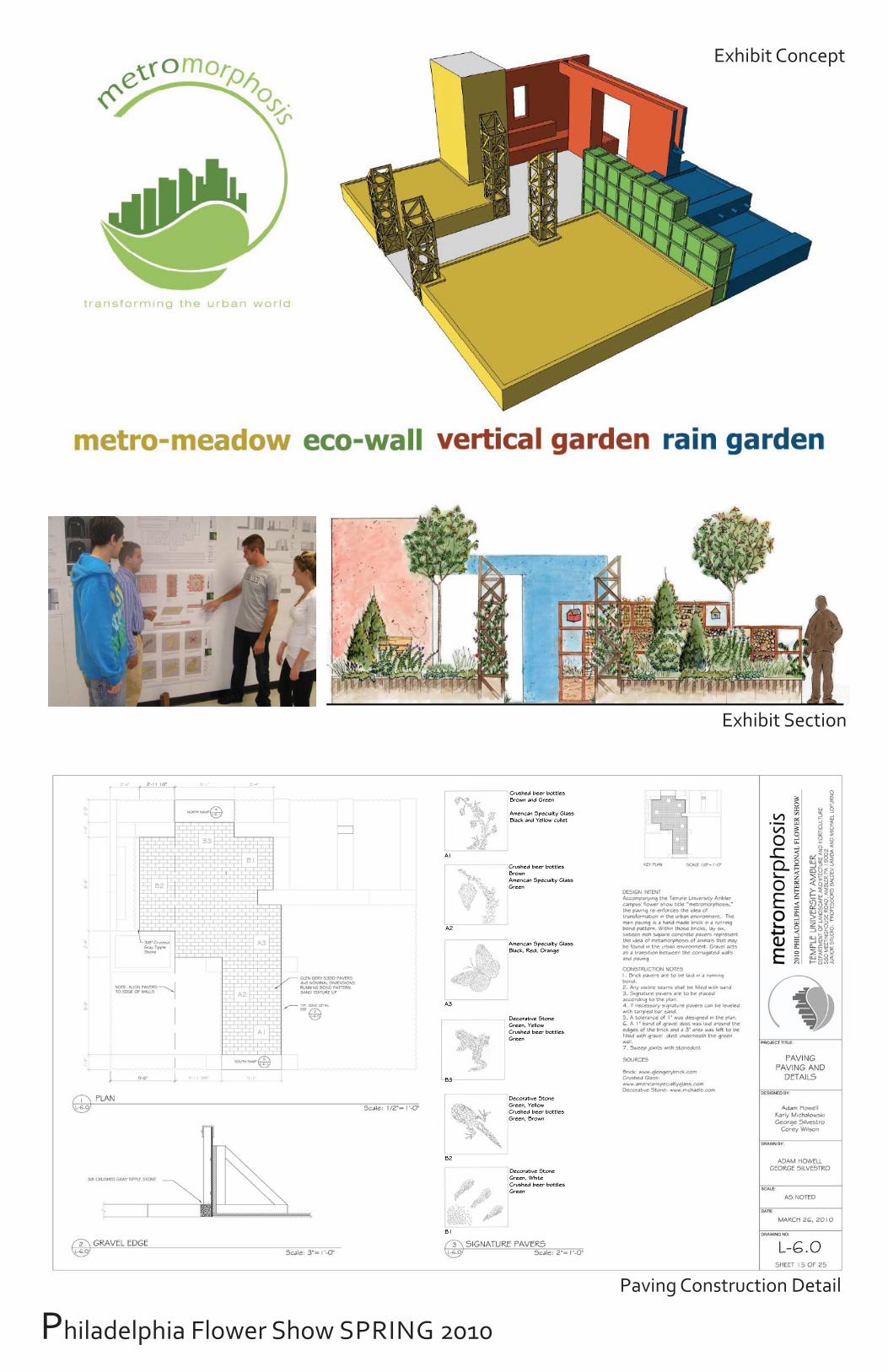
Philadelphia Flower Show SPRING 2010
Exhibit Concept
Exhibit Section
Paving Construction Detail

2010 Philadelphia International Flower Show
Theme: Passport to the World
Temple Exhibit: Metromorphosis Transforming the Urban World.
The Junior class design build studio undertakes the challenge of representing a 22'x 25' life size exhibit representing a theme that the fl ower show provides.
We constructed an exhibit demonstrating sustainable, ecological practices that can be applied in an urban environment. Design features included a metro meadow, green wall, crack garden, livable pond, eco wall, and recycled glass pavers.
Philadelphia Flower Show SPRING 2010 Construction & Built Exhibit

TEMPLE UNIVERSITY SCHOOL OF ENVIRONMENTAL DESIGN LANDSCAPE ARCHITECTURE
2007 - 2011