Geometry of Axisymmetric 3D Origami Consisting of … · 17th international conference on geometry...
10
17 TH INTERNATIONAL CONFERENCE ON GEOMETRY AND GRAPHICS ©2016 ISGG 4–8 AUGUST, 2016, BEIJING, CHINA Paper #11 GEOMETRY OF AXISYMMETRIC 3D ORIGAMI CONSISTING OF TRIANGLE FACETS Yan ZHAO, Yoshihiro KANAMORI, and Jun MITANI University of Tsukuba, Japan ABSTRACT: Origami, the art of folding a piece of paper into a three-dimensional (3D) form, has received much attention in geometry, mathematics, and engineering. In recent years, several approaches for designing 3D origami have been proposed, and many creative origami pieces have been generated. In this paper, we propose a novel 3D origami design method for a new category of 3D origami that is constructed with triangle facets with axisymmetric structure. Our method interactively designs a rotationally-symmetric crease pattern and then analytically calculates the 3D origami model with real-time human interaction. The proposed method enables us to change one parameter to deform the 3D origami model while preserving the axisymmetric structure. By changing another parameter, our method leads to a way of folding a 3D origami model called “arc-direction flat-folding”. By using our prototype system, we interactively explore various origami designs before actually making them. Several 3D origami pieces and folding sequences are presented to demonstrate the validity. Keywords: Computational Origami, Axisymmetric, Deployable Structure, Flat-foldable. 1. INTRODUCTION Origami, the art of folding a piece of paper into a three-dimensional (3D) form, has received much attention in geometry, mathematics, and engi- neering. In recent years, several approaches for designing 3D origami have been proposed, and many creative origami pieces have been gener- ated. In this paper, we propose a novel 3D origami design method for a new category of 3D origami that is constructed with triangle facets with ax- isymmetric structure. Our method interactively designs a rotationally-symmetric crease pattern (i.e., a set of creases on a surface that defines the structure of an origami piece) and then ana- lytically calculates the 3D origami model with real-time human interaction. Specifically, we first design the right part of the 1/N part (N = 8 for this example) of the whole crease pattern (Figure 1 (a)), where N indicates the order of rotational symmetry (N > 2) and the angle θ is determined by N , i.e., θ = 180 ◦ /N . Figure 1: Overview of our method. After the 1/N part has been specified, we gen- erate the rotationally-symmetric crease pattern (Figure 1 (b)) by repeating such part N - 1 times around the origin. Then, we use the crease pat- tern together with a user-specified value ϕ , which is the angle between line P 0 P 1 and the z axis, to calculate a 3D origami model (Figure 1 (c)). Fi- nally, based on the generated 3D model, we deter- mine the mountain and valley assignments on the crease pattern, which are used to fold an origami piece (Figure 1 (d)). We analyze the effects of variations by chang- ing two parameters. By changing the angle ϕ and keeping the crease pattern fixed, we can deform
Transcript of Geometry of Axisymmetric 3D Origami Consisting of … · 17th international conference on geometry...

17TH INTERNATIONAL CONFERENCE ON GEOMETRY AND GRAPHICS ©2016 ISGG4–8 AUGUST, 2016, BEIJING, CHINA
Paper #11
GEOMETRY OF AXISYMMETRIC 3D ORIGAMI CONSISTING OFTRIANGLE FACETS
Yan ZHAO, Yoshihiro KANAMORI, and Jun MITANIUniversity of Tsukuba, Japan
ABSTRACT: Origami, the art of folding a piece of paper into a three-dimensional (3D) form, hasreceived much attention in geometry, mathematics, and engineering. In recent years, several approachesfor designing 3D origami have been proposed, and many creative origami pieces have been generated.In this paper, we propose a novel 3D origami design method for a new category of 3D origami thatis constructed with triangle facets with axisymmetric structure. Our method interactively designsa rotationally-symmetric crease pattern and then analytically calculates the 3D origami model withreal-time human interaction. The proposed method enables us to change one parameter to deform the3D origami model while preserving the axisymmetric structure. By changing another parameter, ourmethod leads to a way of folding a 3D origami model called “arc-direction flat-folding”. By usingour prototype system, we interactively explore various origami designs before actually making them.Several 3D origami pieces and folding sequences are presented to demonstrate the validity.
Keywords: Computational Origami, Axisymmetric, Deployable Structure, Flat-foldable.
1. INTRODUCTIONOrigami, the art of folding a piece of paper into athree-dimensional (3D) form, has received muchattention in geometry, mathematics, and engi-neering. In recent years, several approaches fordesigning 3D origami have been proposed, andmany creative origami pieces have been gener-ated.
In this paper, we propose a novel 3D origamidesign method for a new category of 3D origamithat is constructed with triangle facets with ax-isymmetric structure. Our method interactivelydesigns a rotationally-symmetric crease pattern(i.e., a set of creases on a surface that definesthe structure of an origami piece) and then ana-lytically calculates the 3D origami model withreal-time human interaction.
Specifically, we first design the right part of the1/N part (N = 8 for this example) of the wholecrease pattern (Figure 1 (a)), where N indicatesthe order of rotational symmetry (N > 2) and theangle θ is determined by N, i.e., θ = 180◦/N.
Figure 1: Overview of our method.
After the 1/N part has been specified, we gen-erate the rotationally-symmetric crease pattern(Figure 1 (b)) by repeating such part N−1 timesaround the origin. Then, we use the crease pat-tern together with a user-specified value ϕ , whichis the angle between line P0P1 and the z axis, tocalculate a 3D origami model (Figure 1 (c)). Fi-nally, based on the generated 3D model, we deter-mine the mountain and valley assignments on thecrease pattern, which are used to fold an origamipiece (Figure 1 (d)).
We analyze the effects of variations by chang-ing two parameters. By changing the angle ϕ andkeeping the crease pattern fixed, we can deform

the 3D origami model while preserving devel-opability and the axisymmetric structure. Thisenables us to figure out a folding motion from thefold-state to the flat-state of such a 3D origamimodel. By changing another parameter, ourmethod leads to a way of folding a 3D origamimodel called “arc-direction flat-folding” basedon the flat-foldability of each interior point veri-fied by Kawasaki’s theorem [4] and Maekawa’stheorem [3] (Section 5.2). By using our prototypesystem, we interactively explore various origamidesigns before actually making them. Several3D origami pieces and folding sequences are pre-sented.
2. RELATED WORKIn recent years, origami has advanced signifi-cantly both in quantity and complexity based onthe development of mathematical theories andmore powerful computational resources [2, 13].
TreeMaker is software used to design flat-foldable origami [5]. This software generatesthe crease pattern from a graph tree that repre-sents the base structure of the object by usingthe circle/river packing technique. Tess is a com-puter program that can make crease patterns fororigami tessellations that involve twist folds ina repeating pattern [1]. These approaches focuson flat-foldable origami, but we are aiming atmaking 3D origami with a set of triangle facets.
The Origamizer algorithm, created by Tachi[12], is a very generalized approach that can gen-erate a crease pattern for an arbitrary 3D trian-gle mesh model with topological disc condition.The basic idea is to place clearances betweeneach polygon of the unfolded pattern and con-struct flaps from them inside the target shape; hecalled this “tucking”. This method generates acrease pattern where the “tucks” are placed inthe empty spaces so that the target 3D shape canbe made from a single sheet of paper withoutrequiring any cutting [10]. Origamizer can han-dle 3D rotational shapes; the appearance of thefolded origami piece is equivalent to the targetshape, but the generated pattern might be overly
complicated for a simple model.Mitani proposed a method for designing 3D
origami based on rotational sweep [6] that gen-erates a simpler crease pattern. Another of hismethods [7] can generate 3D shapes that have 3Dtucks with a triangular cross section. Althoughthe outer flags might be considered obtrusive,his methods succeed in generating 3D curvedorigami from simple crease patterns. His method[8], which combines the advantages of the rota-tional sweep and mirror reflection approaches,has been used to build geometrically attractiveorigami pieces. Even though these methods canhandle the axisymmetric structure of origami, itis difficult for them to handle the axisymmetric3D origami consisting of triangle facets (Figures1 and 12).
The interactive system is a creative and explo-rative tool for designers in computer-aided design(CAD) modeling and in 3D origami design. Tachi[11] proposed a design system where the user canintuitively vary a Miura-ori pattern in 3D whilepreserving the developability and other optionalconditions inherent in the origami pattern. An-other interactive system proposed by Mitani andIgarashi [9] allows the user to design 3D curvedorigami surfaces by using mirror operation withselecting and moving a vertex on the 3D origamiwhile maintaining the developability of the result-ing shape. In our work, the system implementingour method interactively designs a rotationally-symmetric crease pattern and then analyticallycalculates the 3D origami model with real-timehuman interaction.
3. DESIGNING CREASE PATTERNIn this section, we describe a rotationally-symmetric crease pattern consisting of trianglefacets. The determination of mountain and valleyassignments on a crease pattern based on the gen-erated 3D origami model is described in Section4.2.
Figure 2(a) shows a 1/N part of the creasepattern, and Figure 2(b) shows the shape in 3Dspace. The symbols in Figure 2 are as follows:
2
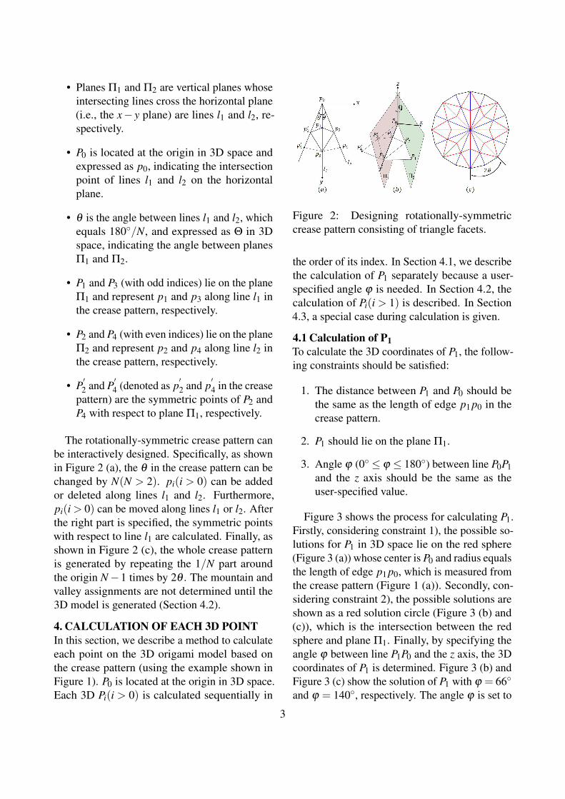
• Planes Π1 and Π2 are vertical planes whoseintersecting lines cross the horizontal plane(i.e., the x− y plane) are lines l1 and l2, re-spectively.
• P0 is located at the origin in 3D space andexpressed as p0, indicating the intersectionpoint of lines l1 and l2 on the horizontalplane.
• θ is the angle between lines l1 and l2, whichequals 180◦/N, and expressed as Θ in 3Dspace, indicating the angle between planesΠ1 and Π2.
• P1 and P3 (with odd indices) lie on the planeΠ1 and represent p1 and p3 along line l1 inthe crease pattern, respectively.
• P2 and P4 (with even indices) lie on the planeΠ2 and represent p2 and p4 along line l2 inthe crease pattern, respectively.
• P′2 and P
′4 (denoted as p
′2 and p
′4 in the crease
pattern) are the symmetric points of P2 andP4 with respect to plane Π1, respectively.
The rotationally-symmetric crease pattern canbe interactively designed. Specifically, as shownin Figure 2 (a), the θ in the crease pattern can bechanged by N(N > 2). pi(i > 0) can be addedor deleted along lines l1 and l2. Furthermore,pi(i > 0) can be moved along lines l1 or l2. Afterthe right part is specified, the symmetric pointswith respect to line l1 are calculated. Finally, asshown in Figure 2 (c), the whole crease patternis generated by repeating the 1/N part aroundthe origin N−1 times by 2θ . The mountain andvalley assignments are not determined until the3D model is generated (Section 4.2).
4. CALCULATION OF EACH 3D POINTIn this section, we describe a method to calculateeach point on the 3D origami model based onthe crease pattern (using the example shown inFigure 1). P0 is located at the origin in 3D space.Each 3D Pi(i > 0) is calculated sequentially in
Figure 2: Designing rotationally-symmetriccrease pattern consisting of triangle facets.
the order of its index. In Section 4.1, we describethe calculation of P1 separately because a user-specified angle ϕ is needed. In Section 4.2, thecalculation of Pi(i > 1) is described. In Section4.3, a special case during calculation is given.
4.1 Calculation of P1To calculate the 3D coordinates of P1, the follow-ing constraints should be satisfied:
1. The distance between P1 and P0 should bethe same as the length of edge p1 p0 in thecrease pattern.
2. P1 should lie on the plane Π1.
3. Angle ϕ (0◦ ≤ ϕ ≤ 180◦) between line P0P1and the z axis should be the same as theuser-specified value.
Figure 3 shows the process for calculating P1.Firstly, considering constraint 1), the possible so-lutions for P1 in 3D space lie on the red sphere(Figure 3 (a)) whose center is P0 and radius equalsthe length of edge p1 p0, which is measured fromthe crease pattern (Figure 1 (a)). Secondly, con-sidering constraint 2), the possible solutions areshown as a red solution circle (Figure 3 (b) and(c)), which is the intersection between the redsphere and plane Π1. Finally, by specifying theangle ϕ between line P1P0 and the z axis, the 3Dcoordinates of P1 is determined. Figure 3 (b) andFigure 3 (c) show the solution of P1 with ϕ = 66◦
and ϕ = 140◦, respectively. The angle ϕ is set to
3
66◦ and fixed throughout the subsequent calcula-tion of the remaining 3D points.
Figure 3: Calculation of P1.
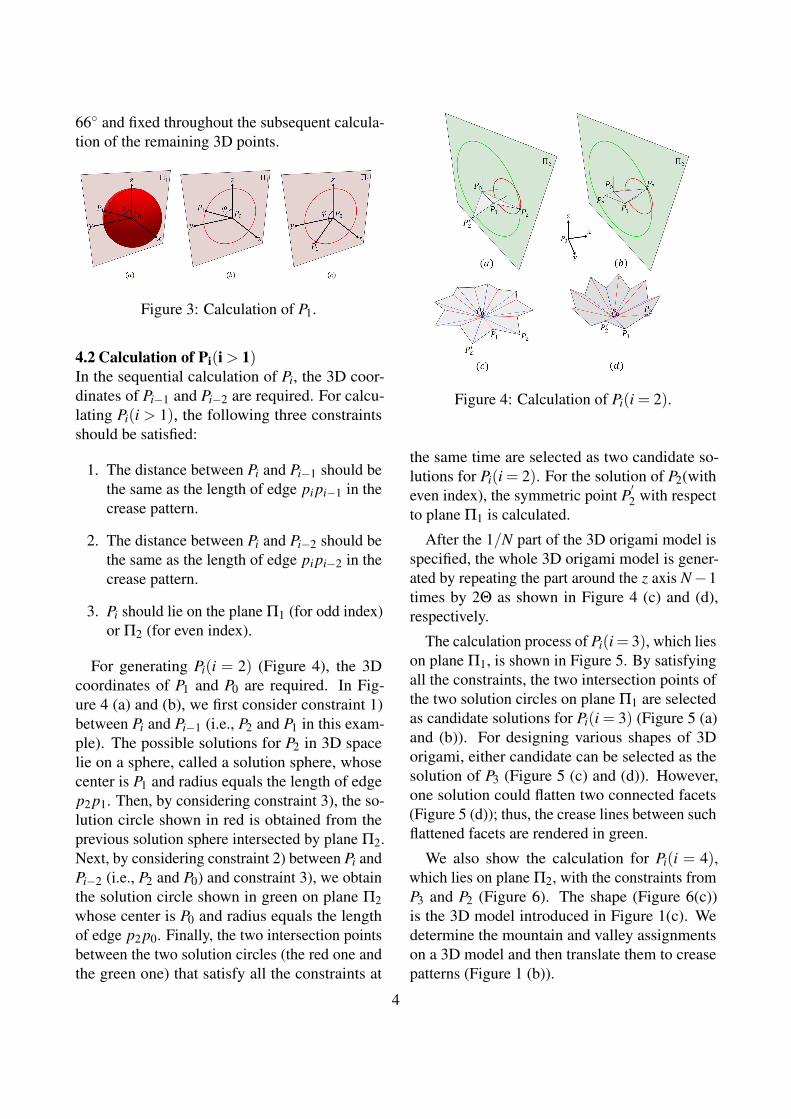
4.2 Calculation of Pi(i > 1)In the sequential calculation of Pi, the 3D coor-dinates of Pi−1 and Pi−2 are required. For calcu-lating Pi(i > 1), the following three constraintsshould be satisfied:
1. The distance between Pi and Pi−1 should bethe same as the length of edge pi pi−1 in thecrease pattern.
2. The distance between Pi and Pi−2 should bethe same as the length of edge pi pi−2 in thecrease pattern.
3. Pi should lie on the plane Π1 (for odd index)or Π2 (for even index).
For generating Pi(i = 2) (Figure 4), the 3Dcoordinates of P1 and P0 are required. In Fig-ure 4 (a) and (b), we first consider constraint 1)between Pi and Pi−1 (i.e., P2 and P1 in this exam-ple). The possible solutions for P2 in 3D spacelie on a sphere, called a solution sphere, whosecenter is P1 and radius equals the length of edgep2 p1. Then, by considering constraint 3), the so-lution circle shown in red is obtained from theprevious solution sphere intersected by plane Π2.Next, by considering constraint 2) between Pi andPi−2 (i.e., P2 and P0) and constraint 3), we obtainthe solution circle shown in green on plane Π2whose center is P0 and radius equals the lengthof edge p2 p0. Finally, the two intersection pointsbetween the two solution circles (the red one andthe green one) that satisfy all the constraints at
Figure 4: Calculation of Pi(i = 2).
the same time are selected as two candidate so-lutions for Pi(i = 2). For the solution of P2(witheven index), the symmetric point P
′2 with respect
to plane Π1 is calculated.
After the 1/N part of the 3D origami model isspecified, the whole 3D origami model is gener-ated by repeating the part around the z axis N−1times by 2Θ as shown in Figure 4 (c) and (d),respectively.
The calculation process of Pi(i= 3), which lieson plane Π1, is shown in Figure 5. By satisfyingall the constraints, the two intersection points ofthe two solution circles on plane Π1 are selectedas candidate solutions for Pi(i = 3) (Figure 5 (a)and (b)). For designing various shapes of 3Dorigami, either candidate can be selected as thesolution of P3 (Figure 5 (c) and (d)). However,one solution could flatten two connected facets(Figure 5 (d)); thus, the crease lines between suchflattened facets are rendered in green.
We also show the calculation for Pi(i = 4),which lies on plane Π2, with the constraints fromP3 and P2 (Figure 6). The shape (Figure 6(c))is the 3D model introduced in Figure 1(c). Wedetermine the mountain and valley assignmentson a 3D model and then translate them to creasepatterns (Figure 1 (b)).
4

Figure 5: Calculation of Pi(i = 3).
Figure 6: Calculation of Pi(i = 4)
4.3 Special Case in Calculation of Pi(i > 1)The candidate solutions for each Pi(i> 1) are twointersection points of the two solution circles asdescribed in Section 4.2. A special case occurswhen the two solution circles are identical. Then,the candidate solutions for Pi(i > 1) are not justtwo points but all the points along the solutioncircle.
Figure 7 shows one example of the specialcase for calculating P3, where ϕ = 90◦ and line
Figure 7: Special case in calculation.
P2P1 is vertical to plane Π1. In such a case, thesolution circle shown in red is constructed bypoints that satisfy constraints 1) and 3). The othersolution circle shown in green is constructed bythe points that satisfy constraint 2) and 3). Bothcircles share the same center P1 and have thesame radius, which is the length of edge p3 p1.As a result, the candidate solutions for P3 in thiscase are not just two points but all the pointsalong the solution circle. In Figure 7, P3 canbe selected arbitrarily on the solution circle todesign various 3D origami models.
5. EFFECTS ON GEOMETRYIn this section, we analyze the effects of varia-tions by changing the parameters including angleϕ (Section 5.1) and angle Θ (Section 5.2).
5.1 Changing angle ϕ
The 3D origami model is a developable surfacethat is isometric, which means that the distancebetween two points on the flat undeveloped planewill be equivalent to the distance between the twocorresponding points on the developed surface.In this section, benefit the process of generatingthe 3D origami model that are
1. The change in angle ϕ only affects P1 di-rectly.
2. Each subsequent Pi(i > 1) is to be recalcu-lated sequentially, which means Pi is notrecalculated until the previous Pi−1 and Pi−2have been recalculated.
3. Each Pi(i > 1) is recalculated based on Pi−1
5
and Pi−2, which have already been recalcu-lated.
, we are able to change only angle ϕ , and theresulting surface remains developablility.
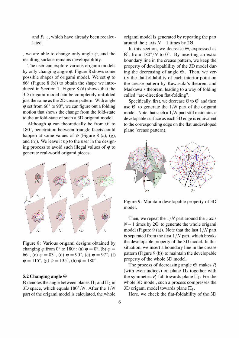
The user can explore various origami modelsby only changing angle ϕ . Figure 8 shows somepossible shapes of origami model. We set ϕ to66◦ (Figure 8 (b)) to obtain the shape we intro-duced in Section 1. Figure 8 (d) shows that the3D origami model can be completely unfoldedjust the same as the 2D crease pattern. With angleϕ set from 66◦ to 90◦, we can figure out a foldingmotion that shows the change from the fold-stateto the unfold-state of such a 3D origami model.
Although ϕ can theoretically be from 0◦ to180◦, penetration between triangle facets couldhappen at some values of ϕ (Figure 8 (a), (g),and (h)). We leave it up to the user in the design-ing process to avoid such illegal values of ϕ togenerate real-world origami pieces.
Figure 8: Various origami designs obtained bychanging ϕ from 0◦ to 180◦: (a) ϕ = 0◦, (b) ϕ =66◦, (c) ϕ = 83◦, (d) ϕ = 90◦, (e) ϕ = 97◦, (f)ϕ = 115◦, (g) ϕ = 135◦, (h) ϕ = 180◦.
5.2 Changing angle Θ
Θ denotes the angle between planes Π1 and Π2 in3D space, which equals 180◦/N. After the 1/Npart of the origami model is calculated, the whole
origami model is generated by repeating the partaround the z axis N−1 times by 2Θ.
In this section, we decrease Θ, expressed asΘ′, from 180◦/N to 0◦. By inserting an extra
boundary line in the crease pattern, we keep theproperty of developablility of the 3D model dur-ing the decreasing of angle Θ
′. Then, we ver-
ify the flat-foldability of each interior point onthe crease pattern by Kawasaki’s theorem andMaekawa’s theorem, leading to a way of foldingcalled “arc-direction flat-folding”.
Specifically, first, we decrease Θ to Θ′and then
use Θ′
to generate the 1/N part of the origamimodel. Note that such a 1/N part still maintains adevelopable surface as each 3D edge is equivalentto the corresponding edge on the flat undevelopedplane (crease pattern).
Figure 9: Maintain developable property of 3Dmodel.
Then, we repeat the 1/N part around the z axisN−1 times by 2Θ
′to generate the whole origami
model (Figure 9 (a)). Note that the last 1/N partis separated from the first 1/N part, which breaksthe developable property of the 3D model. In thissituation, we insert a boundary line in the creasepattern (Figure 9 (b)) to maintain the developableproperty of the whole 3D model.
The process of decreasing angle Θ′
makes Pi(with even indices) on plane Π2 together withthe symmetric P
′i fall towards plane Π1. For the
whole 3D model, such a process compresses the3D origami model towards plane Π1.
Here, we check the flat-foldability of the 3D
6

origami model by verifying the flat-foldabilityof each interior point using Kawasaki’s theo-rem and Maekawa’s theorem. Kawasaki’s the-orem gives a criterion for an origami construc-tion to be flat, which states that a given creasepattern can be folded to a flat origami iff all thesequences of angles α1,α2, · · · ,α2n surroundingeach interior vertex fulfill the following condition:α1 +α3 + · · ·+α2n−1 = α2 +α4 + · · ·+α2n =180◦. Maekawa’s theorem is another criterion,which states that the numbers of mountains andvalleys always differ by 2. Kawasaki’s theo-rem and Maekawa’s theorem are two local flat-foldable conditions.
We show one middle state of the 3D model fordecreasing Θ
′in the left of Figure 10. Note that
the 3D origami model preserves the developa-bility with respect to the updated crease pattern(Figure 9 (b)); thus, the surrounding crease ofeach interior point is fixed during the decreasingof Θ
′to 0◦.
Without loss of generality, we verify the flat-foldability of the interior points by showing thedetails of the crease pattern around P1 and P4,which lie on the planes Π1 and Π2, respectively.Angle αi,k denotes the k−th incident sector angleof pi as shown on the right of Figure 10. Here, wedo not consider p0 since the added boundary linemakes p0 a boundary point (Figure 9 (b)). Specif-ically, for P1, since α1,1 = α1,2 and α1,3 = α1,4and thus α1,1+α1,3 = α1,2+α1,4 = 180◦, whichsatisfies Kawasaki’s theorem. Also, since thenumber of mountain lines (3) minus the num-ber of valley lines (1) equals 2, Maekawa’stheorem is satisfied. Similarly, for P4, sinceα4,1 =α4,2, α4,3 =α4,6 and α4,4 =α4,5, and thusα4,1 + α4,3 + α4,5 = α4,2 + α4,4 + α4,6 = 180◦,which satisfies Kawasaki’s theorem. Also, sincethe number of mountain lines (4) minus the num-ber of valley lines (2) equals 2, Maekawa’s theo-rem is satisfied.
If all interior points satisfy Kawasaki’s theo-rem and Maekawa’s theorem, we can decreaseΘ′
to 0◦ to fold the whole 3D model around the zaxis (Figure 11), which is a way of folding called
Figure 10: Check flat-foldability with Kawasaki’theorem and Maekawa’s theorem.
Figure 11: Arc-direction flat-folding sequence.
“arc-direction flat-folding”.
6. RESULTSWe show several resulting origami pieces in Fig-ure 12, where the first row is the crease pattern,the second row is the 3DCG model, and the thirdrow is the photo of the origami piece.
Figure 12 (a), (b), and (c) show the 3D origamipieces constructed with triangle facets. By ap-plying the special case, we design origami piecesthat have both a flat center area and triangle facets,as shown in Figure 13. In Figure 14, we show thefolding motion of the origami models from thefold-state to the flat-state (Figure 12 (a), (b), and(c)) by changing parameter ϕ .
7
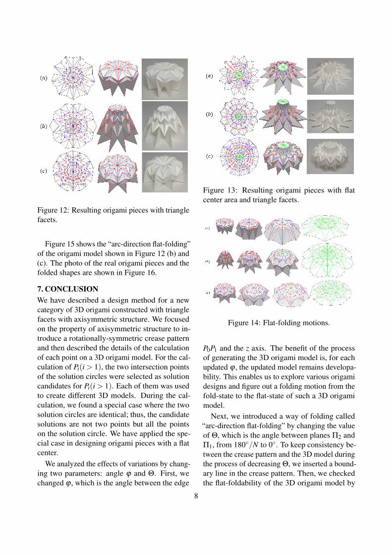
Figure 12: Resulting origami pieces with trianglefacets.
Figure 15 shows the “arc-direction flat-folding”of the origami model shown in Figure 12 (b) and(c). The photo of the real origami pieces and thefolded shapes are shown in Figure 16.
7. CONCLUSIONWe have described a design method for a newcategory of 3D origami constructed with trianglefacets with axisymmetric structure. We focusedon the property of axisymmetric structure to in-troduce a rotationally-symmetric crease patternand then described the details of the calculationof each point on a 3D origami model. For the cal-culation of Pi(i > 1), the two intersection pointsof the solution circles were selected as solutioncandidates for Pi(i > 1). Each of them was usedto create different 3D models. During the cal-culation, we found a special case where the twosolution circles are identical; thus, the candidatesolutions are not two points but all the pointson the solution circle. We have applied the spe-cial case in designing origami pieces with a flatcenter.
We analyzed the effects of variations by chang-ing two parameters: angle ϕ and Θ. First, wechanged ϕ , which is the angle between the edge
Figure 13: Resulting origami pieces with flatcenter area and triangle facets.
Figure 14: Flat-folding motions.
P0P1 and the z axis. The benefit of the processof generating the 3D origami model is, for eachupdated ϕ , the updated model remains developa-bility. This enables us to explore various origamidesigns and figure out a folding motion from thefold-state to the flat-state of such a 3D origamimodel.
Next, we introduced a way of folding called“arc-direction flat-folding” by changing the valueof Θ, which is the angle between planes Π2 andΠ1, from 180◦/N to 0◦. To keep consistency be-tween the crease pattern and the 3D model duringthe process of decreasing Θ, we inserted a bound-ary line in the crease pattern. Then, we checkedthe flat-foldability of the 3D origami model by
8

Figure 15: Arc-direction flat-folding sequences.
Figure 16: Arc-direction flat-folding of realorigami pieces.
verifying the flat-foldability of each interior pointusing Kawasaki’s theorem and Maekawa’s theo-rem. We showed the “arc-direction flat-folding”sequences and practiced such folding in realorigami pieces.
One future work is to use tuck folding technol-ogy to design axisymmetric 3D origami consist-ing of triangle facets.
REFERENCES[1] A. Bateman. Paper mosaic origami tessel-
lations. http://www.papermosaics.co.uk/software.html.
[2] E. D. Demaine and J. ORourke. Geometricfolding algorithms. Cambridge universitypress Cambridge, 2007.
[3] K. Kasahara and J. Maekawa. Viva!origami, 1983.
[4] T. Kawasaki. On the relation betweenmountain-creases and valley-creases of a
flat origami. In Proceedings of the 1st Inter-national Meeting of Origami Science andTechnology, pages 229–237. 1989.
[5] R. J. Lang. Treemaker. RobertJ. lang Origami, 2006. http://www.langorigami.com/article/treemaker/.
[6] J. Mitani. A design method for 3D origamibased on rotational sweep. Computer-Aided Design and Applications, 6(1): 69–79, 2009.
[7] J. Mitani. A design method for axisym-metric curved origami with triangular prismprotrusions. In Origami 5: Fifth Interna-tional Meeting of Origami Science, Math-ematics, and Education, page 437. CRCPress, 2011.
[8] J. Mitani. Column-shaped origami designbased on mirror reflections. Journal forGeometry and Graphics, 16(2): 185–194,2012.
[9] J. Mitani and T. Igarashi. Interactive de-sign of planar curved folding by reflection.Pacific Graphics (short paper), 2011.
[10] T. Tachi. 3D origami design based ontucking molecule. In The Fourth Interna-tional Conference on Origami in Science,Mathematics, and Education, R. Lang, ed.,Pasadena, pages 259–272. 2009.
9

[11] T. Tachi. Freeform variations of origami. J.Geom. Graph, 14(2): 203–215, 2010.
[12] T. Tachi. Origamizing polyhedral sur-faces. Visualization and Computer Graph-ics, IEEE Transactions on, 16(2): 298–311,2010.
[13] P. Wang-Iverson, R. J. Lang, and Y. Mark.Origami 5: Fifth International Meeting ofOrigami Science, Mathematics, and Educa-tion. CRC Press, 2011.
ABOUT AUTHORS1. Yan Zhao, Ph.D. student at the Depart-
ment of Computer Science, University ofTsukuba.
2. Yoshihiro Kanamori, Assistant Professor atthe Department of Computer Science, Uni-versity of Tsukuba.
3. Jun Mitani, Professor at the Department ofComputer Science, University of Tsukuba.
10