
Geometric modelingchriswilson/FEA/ANSYS/FEM...Geometric modeling 4 Computational Mechanics, AAU,...
53
Computational Mechanics, AAU, Esbjerg FEM – ANSYS Classic Course in FEM – ANSYS Classic Geometric modeling
Transcript of Geometric modelingchriswilson/FEA/ANSYS/FEM...Geometric modeling 4 Computational Mechanics, AAU,...
Computational Mechanics, AAU, EsbjergFEM – ANSYS Classic
Course inFEM – ANSYS Classic
Geometric modeling
Geometric modeling 2Computational Mechanics, AAU, EsbjergFEM – ANSYS Classic
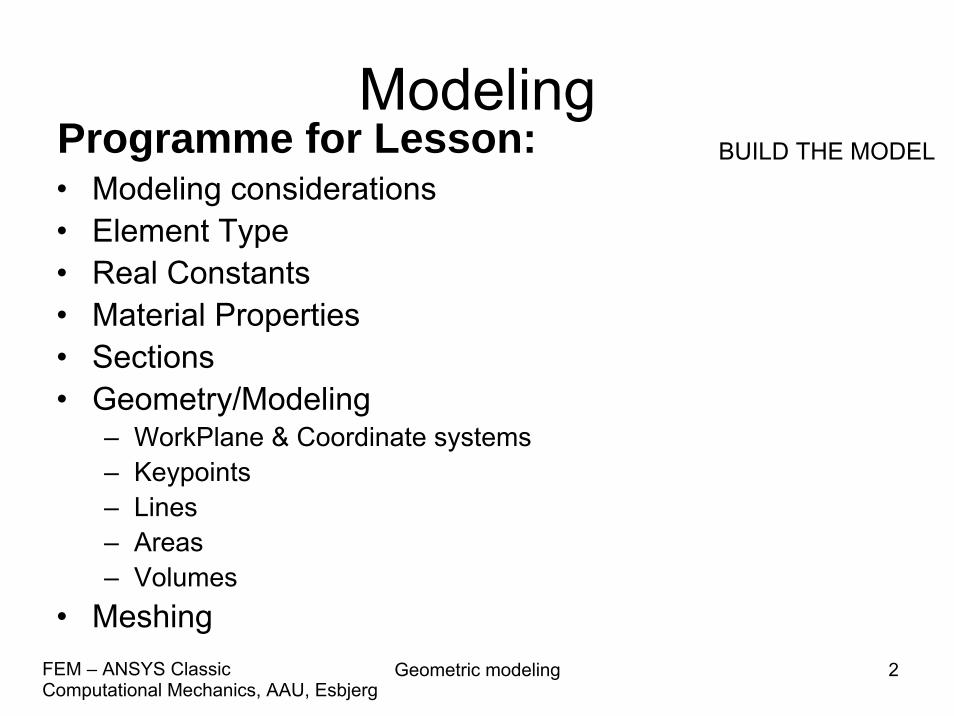
ModelingProgramme for Lesson: BUILD THE MODEL
• Modeling considerations• Element Type• Real Constants• Material Properties• Sections• Geometry/Modeling
– WorkPlane & Coordinate systems– Keypoints– Lines– Areas– Volumes
• Meshing
Geometric modeling 3Computational Mechanics, AAU, EsbjergFEM – ANSYS Classic
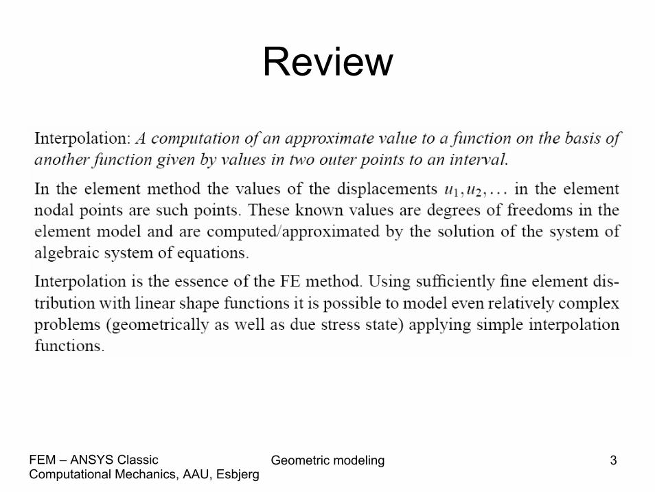
Review

Geometric modeling 4Computational Mechanics, AAU, EsbjergFEM – ANSYS Classic
Review• Equilibrium for nodal forces and -moments is satisfied.• Compatibility is satisfied in FE nodes.• Equilibrium is not satisfied across the element
boundaries.• Compatibility is not necessarily satisfied across element
boundaries. For the triangular and the rectangular element compatibility is satisfied as the element sides remain straight under deformation.
• Equilibrium is not satisfied for the individual element (due to the weak formulation – integral form).
• Compatibility is satisfied for the individual element, i.e. the displacement field must be continuous. This is automatically achieved by a proper formulation of the element shape functions, i.e. polynomial formulation.
Geometric modeling 5Computational Mechanics, AAU, EsbjergFEM – ANSYS Classic
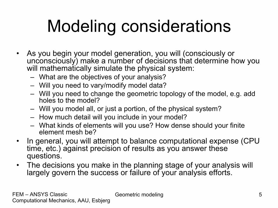
Modeling considerations• As you begin your model generation, you will (consciously or
unconsciously) make a number of decisions that determine how youwill mathematically simulate the physical system:– What are the objectives of your analysis?– Will you need to vary/modify model data?– Will you need to change the geometric topology of the model, e.g. add
holes to the model?– Will you model all, or just a portion, of the physical system? – How much detail will you include in your model? – What kinds of elements will you use? How dense should your finite
element mesh be? • In general, you will attempt to balance computational expense (CPU
time, etc.) against precision of results as you answer these questions.
• The decisions you make in the planning stage of your analysis will largely govern the success or failure of your analysis efforts.
Geometric modeling 6Computational Mechanics, AAU, EsbjergFEM – ANSYS Classic
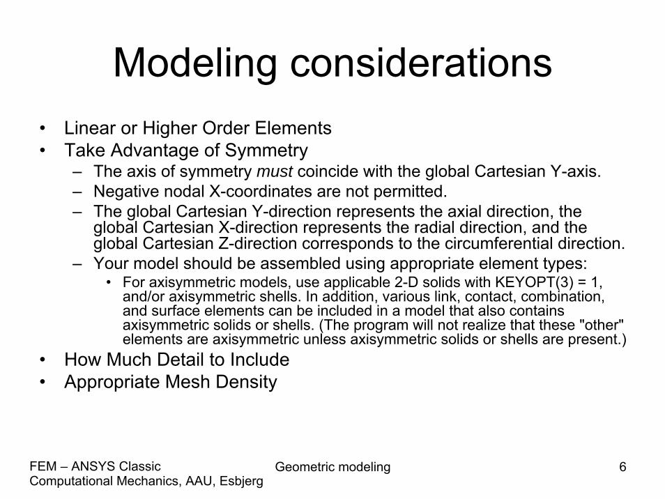
Modeling considerations• Linear or Higher Order Elements• Take Advantage of Symmetry
– The axis of symmetry must coincide with the global Cartesian Y-axis.– Negative nodal X-coordinates are not permitted.– The global Cartesian Y-direction represents the axial direction, the
global Cartesian X-direction represents the radial direction, and the global Cartesian Z-direction corresponds to the circumferential direction.
– Your model should be assembled using appropriate element types: • For axisymmetric models, use applicable 2-D solids with KEYOPT(3) = 1,
and/or axisymmetric shells. In addition, various link, contact, combination, and surface elements can be included in a model that also contains axisymmetric solids or shells. (The program will not realize that these "other" elements are axisymmetric unless axisymmetric solids or shells are present.)
• How Much Detail to Include• Appropriate Mesh Density
Geometric modeling 7Computational Mechanics, AAU, EsbjergFEM – ANSYS Classic
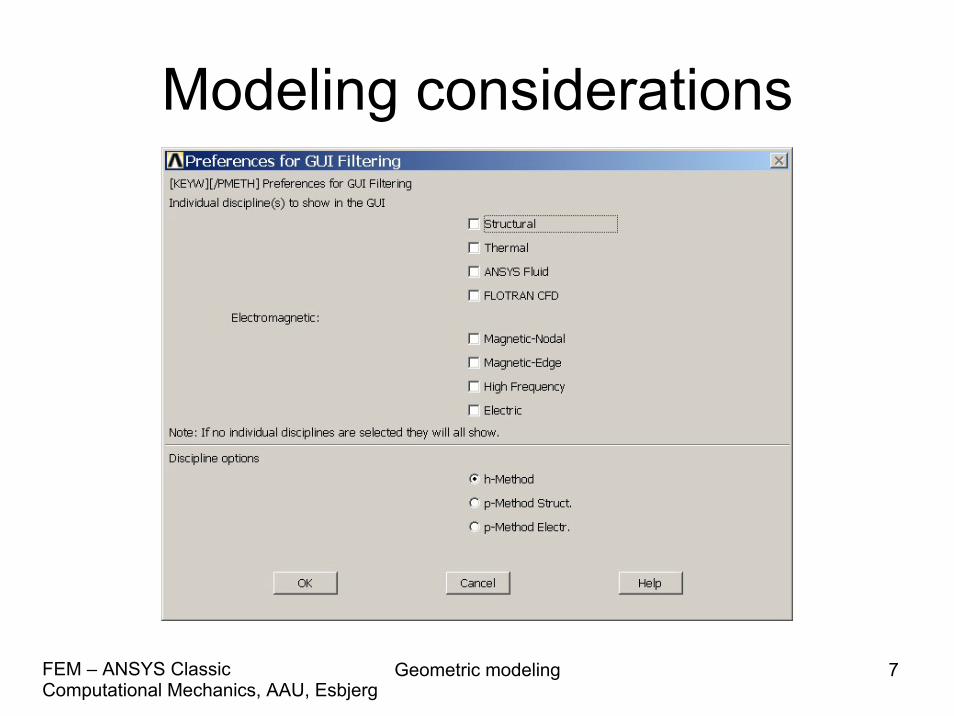
Modeling considerations
Geometric modeling 8Computational Mechanics, AAU, EsbjergFEM – ANSYS Classic
Modeling considerations
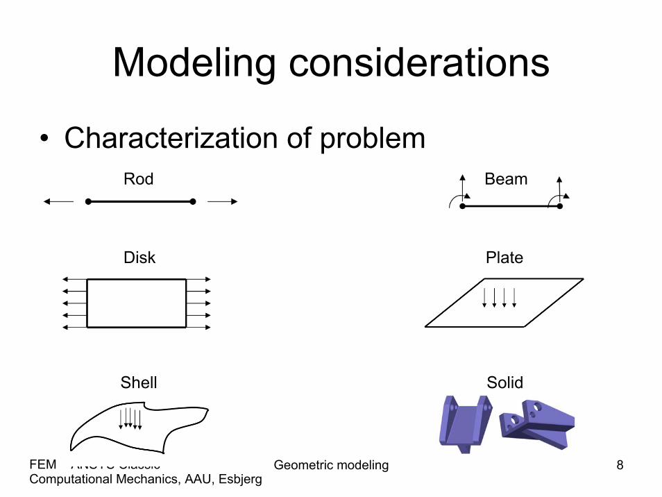
• Characterization of problemRod Beam
Disk Plate
Shell Solid

Geometric modeling 9Computational Mechanics, AAU, EsbjergFEM – ANSYS Classic
Modeling considerations
• The ANSYS program does not assume a system of units for your analysis.
• Units must however be consistent for all input data.
Geometric modeling 10Computational Mechanics, AAU, EsbjergFEM – ANSYS Classic
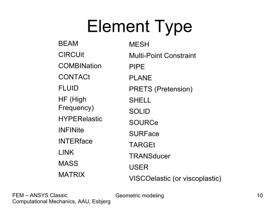
Element TypeBEAMCIRCUitCOMBINationCONTACtFLUIDHF (HighFrequency)HYPERelasticINFINiteINTERfaceLINKMASSMATRIX
MESHMulti-Point ConstraintPIPEPLANEPRETS (Pretension)SHELLSOLIDSOURCeSURFaceTARGEtTRANSducerUSERVISCOelastic (or viscoplastic)
Geometric modeling 11Computational Mechanics, AAU, EsbjergFEM – ANSYS Classic
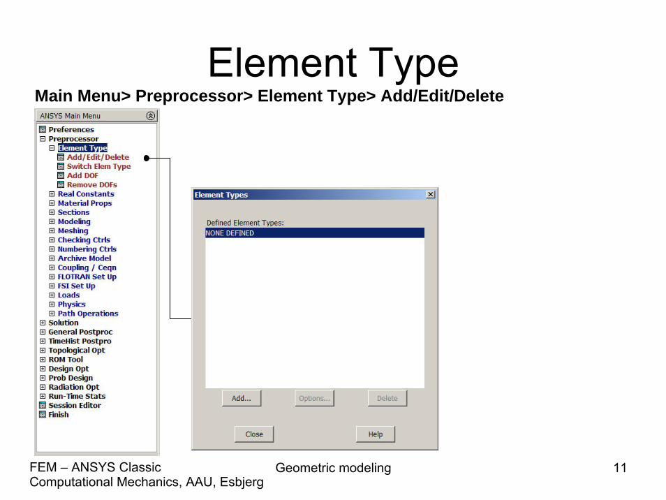
Element TypeMain Menu> Preprocessor> Element Type> Add/Edit/Delete
Geometric modeling 12Computational Mechanics, AAU, EsbjergFEM – ANSYS Classic
Element Type
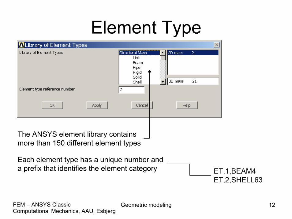
The ANSYS element library containsmore than 150 different element types
Each element type has a unique number and a prefix that identifies the element category ET,1,BEAM4
ET,2,SHELL63

Geometric modeling 13Computational Mechanics, AAU, EsbjergFEM – ANSYS Classic
Element Type
• Many element types have additional options, known as KEYOPTs, and are referred to as KEYOPT(1), KEYOPT(2), etc. e.g.:– KEYOPT(9) for BEAM4 allows you to choose results
to be calculated at intermediate locations on each element
– KEYOPT(3) for SHELL63 allows you to suppress extra displacement shapes
Geometric modeling 14Computational Mechanics, AAU, EsbjergFEM – ANSYS Classic
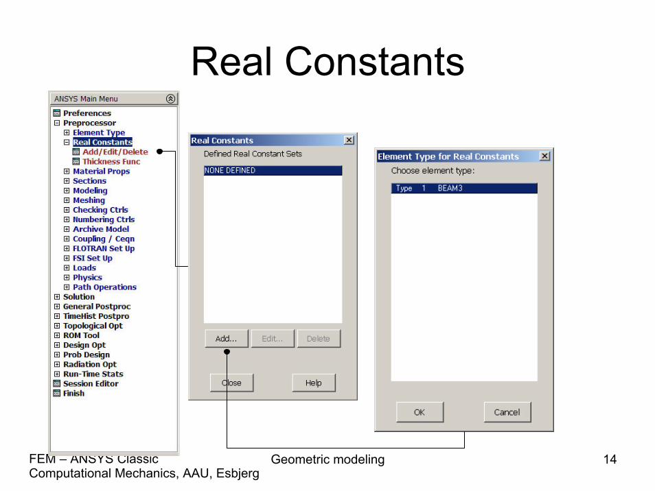
Real Constants
Geometric modeling 15Computational Mechanics, AAU, EsbjergFEM – ANSYS Classic
Real Constants• Element real constants are properties that depend on the
element type, such as cross-sectional properties of a beam element– e.g. real constants for BEAM3, the 2-D beam element, are area
(AREA), moment of inertia (IZZ), height (HEIGHT), shear deflection constant (SHEARZ), initial strain (ISTRN), and added mass per unit length (ADDMAS).
• Not all element types require real constants, and different elements of the same type may have different real constant values.
Geometric modeling 16Computational Mechanics, AAU, EsbjergFEM – ANSYS Classic
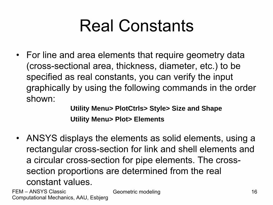
Real Constants• For line and area elements that require geometry data
(cross-sectional area, thickness, diameter, etc.) to be specified as real constants, you can verify the input graphically by using the following commands in the order shown:
• ANSYS displays the elements as solid elements, using a rectangular cross-section for link and shell elements and a circular cross-section for pipe elements. The cross-section proportions are determined from the real constant values.
Utility Menu> PlotCtrls> Style> Size and ShapeUtility Menu> Plot> Elements
Geometric modeling 17Computational Mechanics, AAU, EsbjergFEM – ANSYS Classic
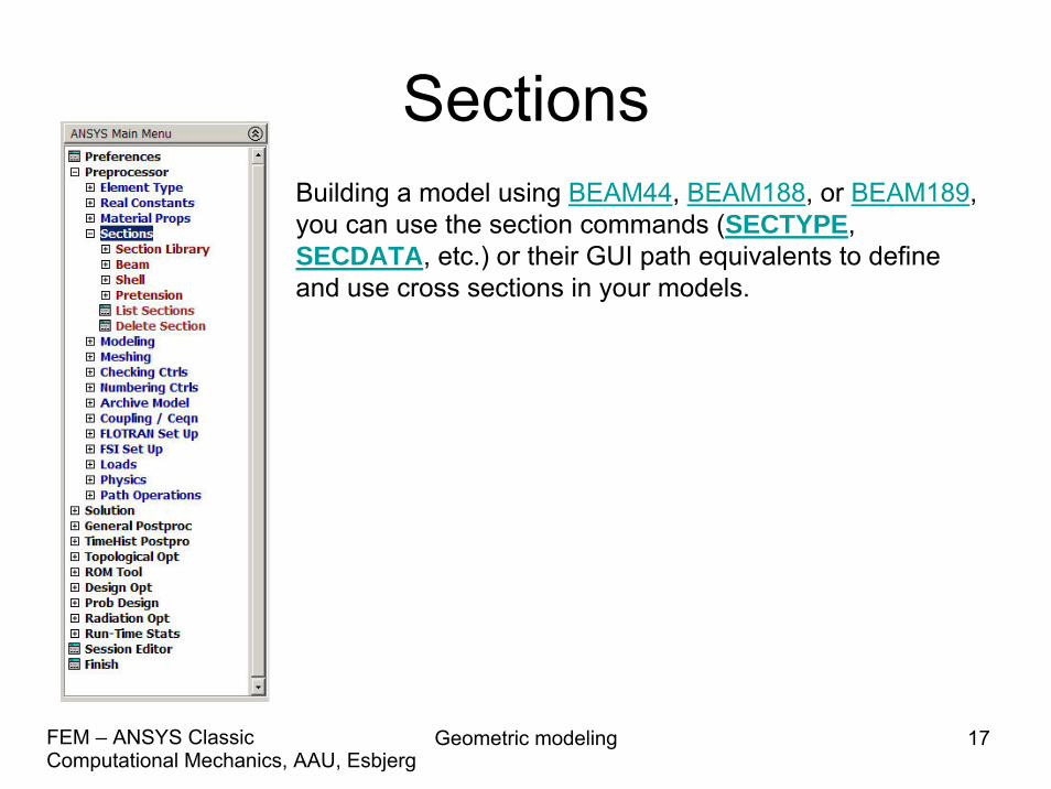
SectionsBuilding a model using BEAM44, BEAM188, or BEAM189,you can use the section commands (SECTYPE,SECDATA, etc.) or their GUI path equivalents to define and use cross sections in your models.
Geometric modeling 18Computational Mechanics, AAU, EsbjergFEM – ANSYS Classic
Sections
• A cross section defines the geometry of the beam in a plane perpendicular to the beam axial direction. ANSYS supplies a library of eleven commonly-used beam cross section shapes, and permits user-defined cross section shapes.
• When a cross section is defined, ANSYS builds a numeric model using a nine node cell for determining the properties (Iyy, Izz, etc.) of the section and for the solution to the Poisson's equation for torsional behaviour.

Geometric modeling 19Computational Mechanics, AAU, EsbjergFEM – ANSYS Classic
Sections
Geometric modeling 20Computational Mechanics, AAU, EsbjergFEM – ANSYS Classic
Geometry/Modelling
• Creating a solid model within ANSYS.• Using direct generation.• Importing a model created in a computer-
aided design (CAD) system.
Geometric modeling 21Computational Mechanics, AAU, EsbjergFEM – ANSYS Classic
Coordinate systems• Global and local coordinate systems are used to locate geometry
items (nodes, keypoints, etc.) in space.• The display coordinate system determines the system in which
geometry items are listed or displayed.• The nodal coordinate system defines the degree of freedom
directions at each node and the orientation of nodal results data.• The element coordinate system determines the orientation of
material properties and element results data.• The results coordinate system is used to transform nodal or element
results data to a particular coordinate system for listings, displays, or general postprocessing operations (POST1).
• The working plane, which is separate from the coordinate systemsdiscussed in this chapter, is used to locate geometric primitives during the modeling process.
Geometric modeling 22Computational Mechanics, AAU, EsbjergFEM – ANSYS Classic
Coordinate systems
• (a) Cartesian (X, Y, Z components) coordinate system 0 (C.S.0)
• (b) Cylindrical (R, θ, Z components) coordinate system 1 (C.S.1)
• (c) Spherical (R, θ, φ components) coordinate system 2 (C.S.2)
• (d) Cylindrical (R, θ, Y components) coordinate system 5 (C.S.5)
Geometric modeling 23Computational Mechanics, AAU, EsbjergFEM – ANSYS Classic
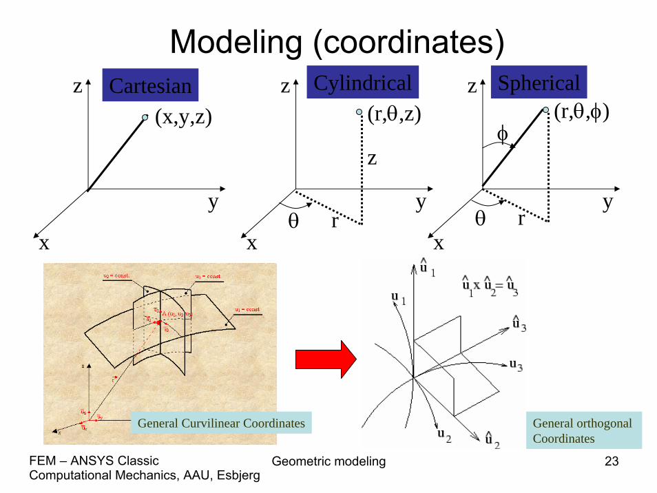
Modeling (coordinates)
x
y
z
x
y
z
x
y
z(r,θ,z)
z
rθ
(r,θ,φ)
rθ
φ(x,y,z)
Cartesian Cylindrical Spherical
General Curvilinear Coordinates General orthogonal Coordinates
Geometric modeling 24Computational Mechanics, AAU, EsbjergFEM – ANSYS Classic
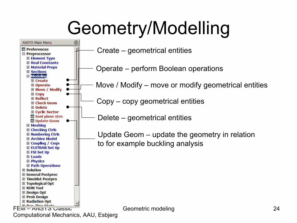
Geometry/ModellingCreate – geometrical entities
Operate – perform Boolean operations
Move / Modify – move or modify geometrical entities
Copy – copy geometrical entities
Delete – geometrical entities
Update Geom – update the geometry in relationto for example buckling analysis

Geometric modeling 25Computational Mechanics, AAU, EsbjergFEM – ANSYS Classic
Modeling - Create
• The hierarchy of modeling entities is as listed below:– Elements (and Element Loads)– Nodes (and Nodal Loads)– Volumes (and Solid-Model Body Loads)– Areas (and Solid-Model Surface Loads)– Lines (and Solid-Model Line Loads)– Keypoints (and Solid-Model Point Loads)
Geometric modeling 26Computational Mechanics, AAU, EsbjergFEM – ANSYS Classic
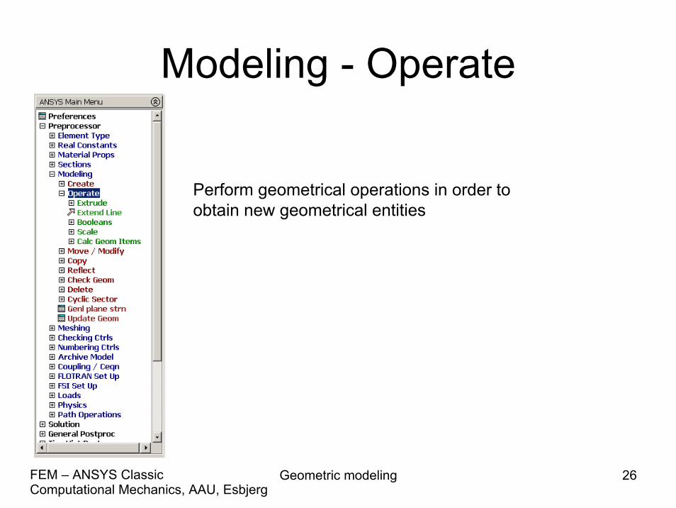
Modeling - Operate
Perform geometrical operations in order to obtain new geometrical entities

Geometric modeling 27Computational Mechanics, AAU, EsbjergFEM – ANSYS Classic
Modeling - Move/Modify
Move or modify locations or sizes of geometrical entities
Geometric modeling 28Computational Mechanics, AAU, EsbjergFEM – ANSYS Classic
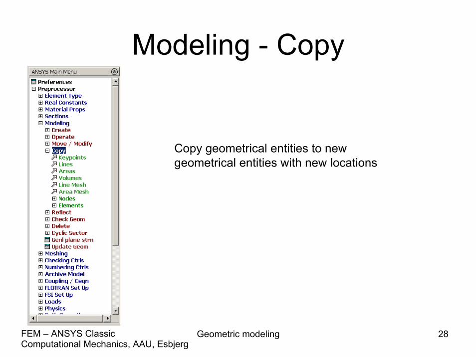
Modeling - Copy
Copy geometrical entities to new geometrical entities with new locations
Geometric modeling 29Computational Mechanics, AAU, EsbjergFEM – ANSYS Classic
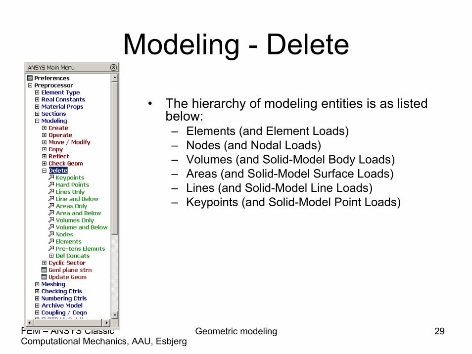
Modeling - Delete
• The hierarchy of modeling entities is as listed below:– Elements (and Element Loads)– Nodes (and Nodal Loads)– Volumes (and Solid-Model Body Loads)– Areas (and Solid-Model Surface Loads)– Lines (and Solid-Model Line Loads)– Keypoints (and Solid-Model Point Loads)
Geometric modeling 30Computational Mechanics, AAU, EsbjergFEM – ANSYS Classic
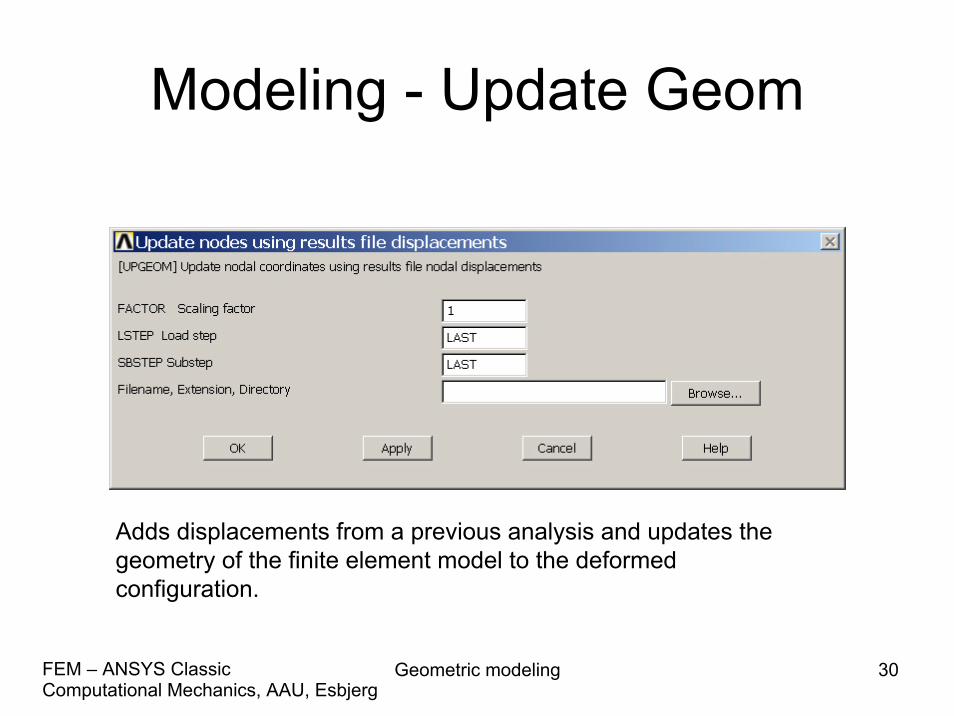
Modeling - Update Geom
Adds displacements from a previous analysis and updates the geometry of the finite element model to the deformed configuration.
Geometric modeling 31Computational Mechanics, AAU, EsbjergFEM – ANSYS Classic
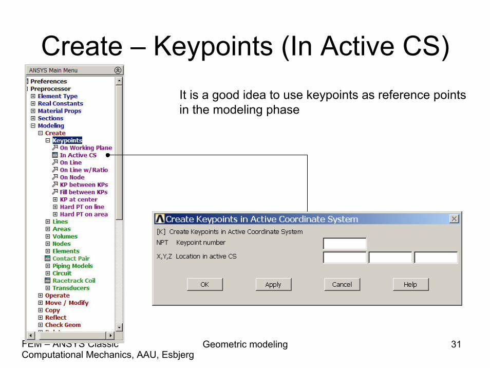
Create – Keypoints (In Active CS)It is a good idea to use keypoints as reference pointsin the modeling phase

Geometric modeling 32Computational Mechanics, AAU, EsbjergFEM – ANSYS Classic
Create – Lines (Straight Line)

Geometric modeling 33Computational Mechanics, AAU, EsbjergFEM – ANSYS Classic
Create – Lines - Arcs

Geometric modeling 34Computational Mechanics, AAU, EsbjergFEM – ANSYS Classic
Create – Areas (By 2 Corners)
Geometric modeling 35Computational Mechanics, AAU, EsbjergFEM – ANSYS Classic
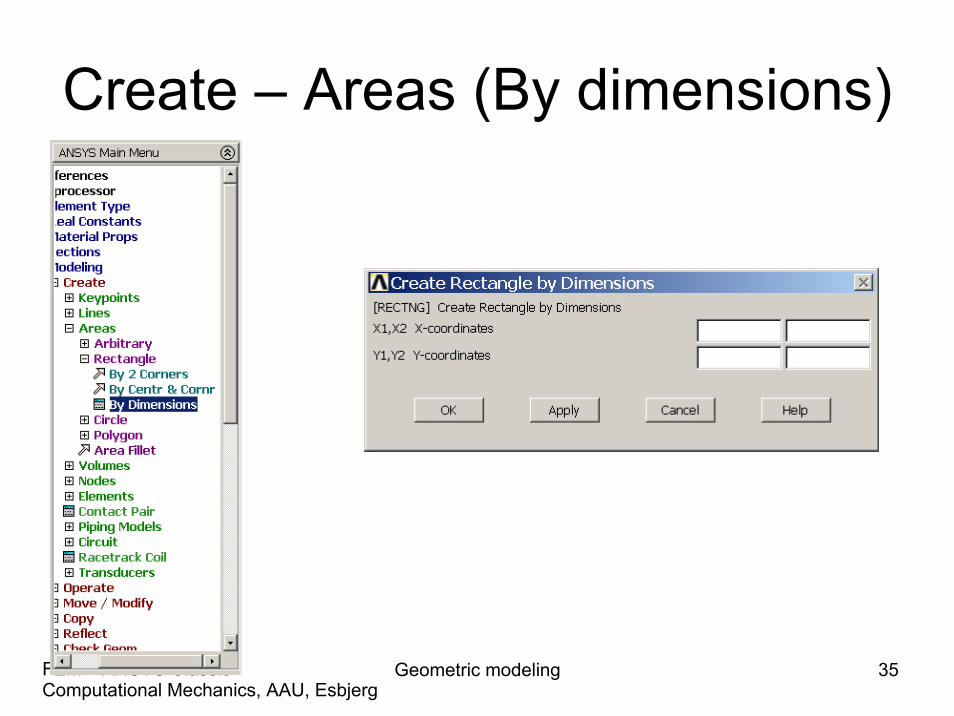
Create – Areas (By dimensions)
Geometric modeling 36Computational Mechanics, AAU, EsbjergFEM – ANSYS Classic
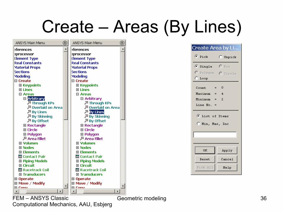
Create – Areas (By Lines)

Geometric modeling 37Computational Mechanics, AAU, EsbjergFEM – ANSYS Classic
Create - Volumes
Geometric modeling 38Computational Mechanics, AAU, EsbjergFEM – ANSYS Classic
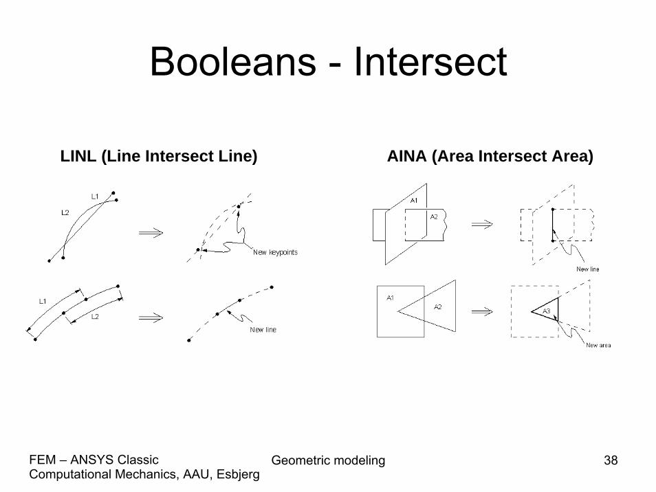
Booleans - Intersect
AINA (Area Intersect Area)LINL (Line Intersect Line)
Geometric modeling 39Computational Mechanics, AAU, EsbjergFEM – ANSYS Classic
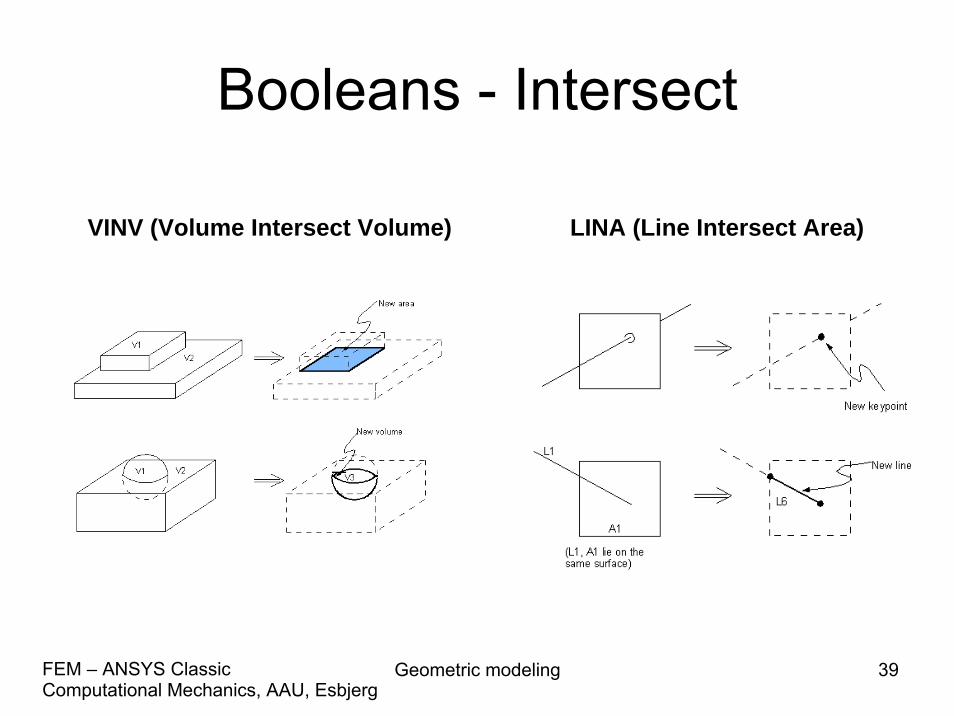
Booleans - Intersect
LINA (Line Intersect Area)VINV (Volume Intersect Volume)
Geometric modeling 40Computational Mechanics, AAU, EsbjergFEM – ANSYS Classic
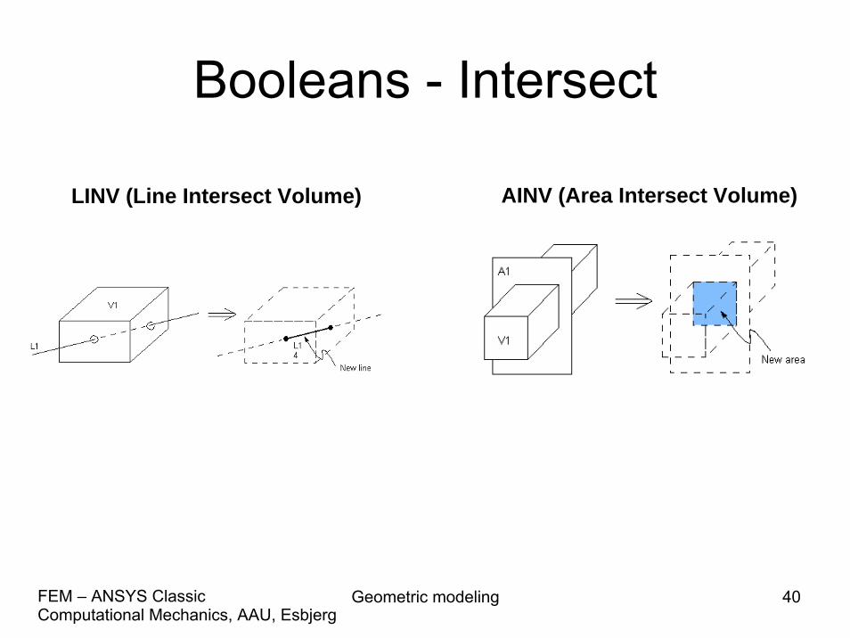
Booleans - Intersect
LINV (Line Intersect Volume) AINV (Area Intersect Volume)
Geometric modeling 41Computational Mechanics, AAU, EsbjergFEM – ANSYS Classic
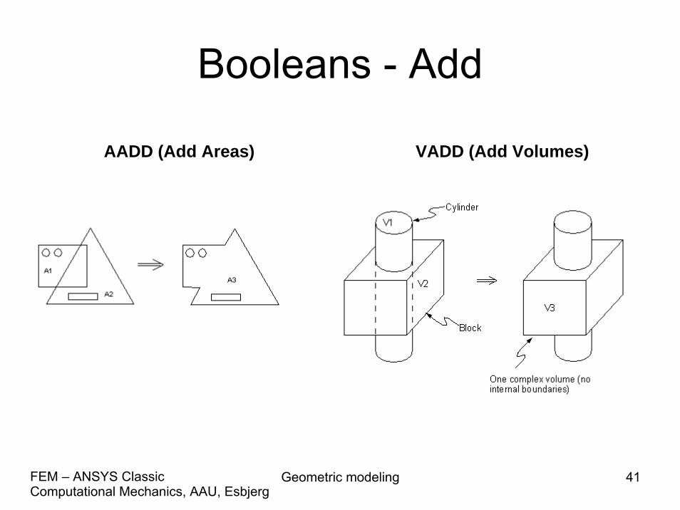
Booleans - Add
VADD (Add Volumes) AADD (Add Areas)
Geometric modeling 42Computational Mechanics, AAU, EsbjergFEM – ANSYS Classic
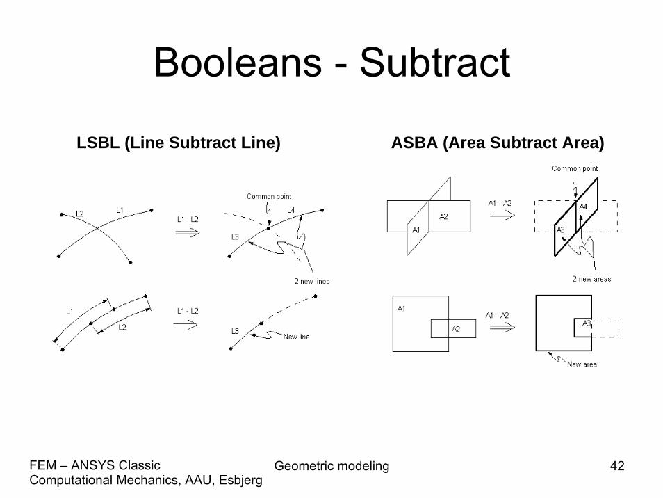
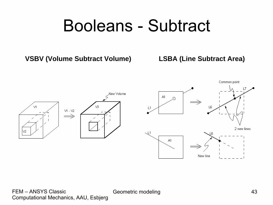
Booleans - Subtract
ASBA (Area Subtract Area)LSBL (Line Subtract Line)
Geometric modeling 43Computational Mechanics, AAU, EsbjergFEM – ANSYS Classic
Booleans - Subtract
LSBA (Line Subtract Area)VSBV (Volume Subtract Volume)
Geometric modeling 44Computational Mechanics, AAU, EsbjergFEM – ANSYS Classic
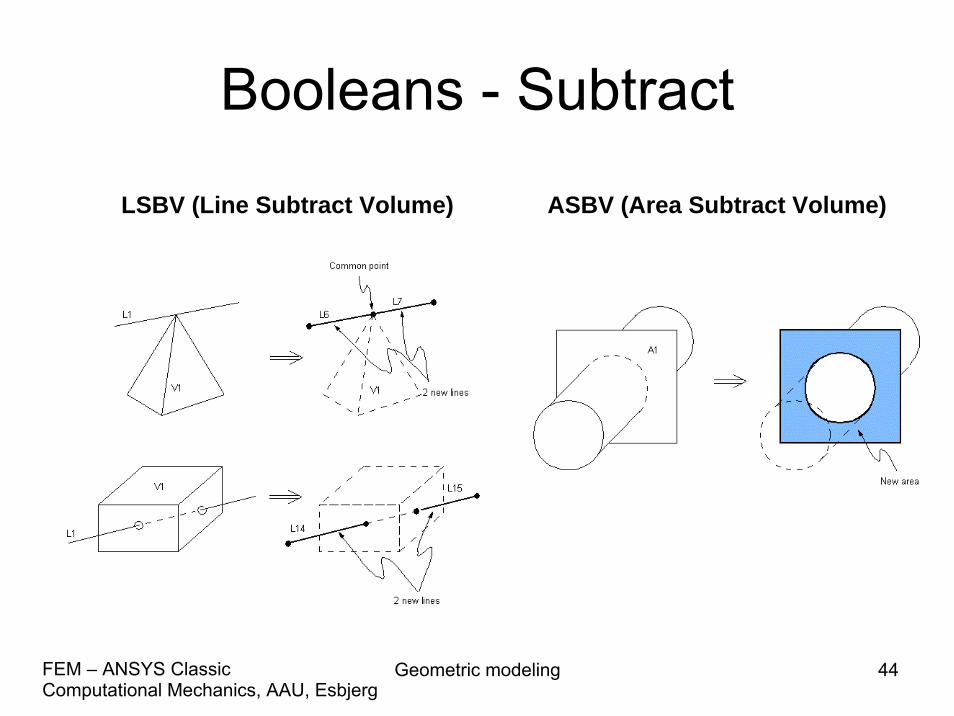
Booleans - Subtract
ASBV (Area Subtract Volume)LSBV (Line Subtract Volume)
Geometric modeling 45Computational Mechanics, AAU, EsbjergFEM – ANSYS Classic
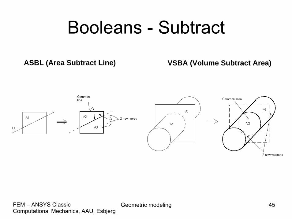
Booleans - Subtract
VSBA (Volume Subtract Area)ASBL (Area Subtract Line)

Geometric modeling 46Computational Mechanics, AAU, EsbjergFEM – ANSYS Classic
Booleans - Overlap
VOVLAP (Volume Overlap Volume)
AOVLAP (Area Overlap Area) LOVLAP (Line Overlap Line)

Geometric modeling 47Computational Mechanics, AAU, EsbjergFEM – ANSYS Classic
Booleans - Glue
VGLUE (Volume Glue Volume)
AGLUE (Area Glue Area)LGLUE (Line Glue Line)
Geometric modeling 48Computational Mechanics, AAU, EsbjergFEM – ANSYS Classic
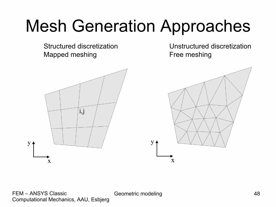
Mesh Generation ApproachesUnstructured discretizationFree meshing
Structured discretizationMapped meshing
Geometric modeling 49Computational Mechanics, AAU, EsbjergFEM – ANSYS Classic
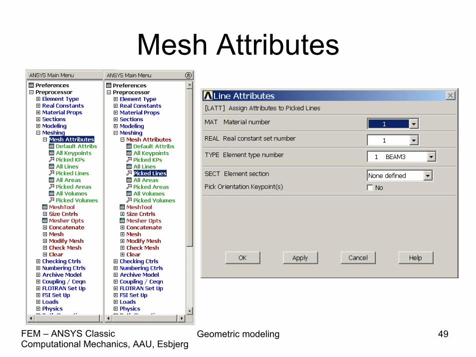
Mesh Attributes
Geometric modeling 50Computational Mechanics, AAU, EsbjergFEM – ANSYS Classic
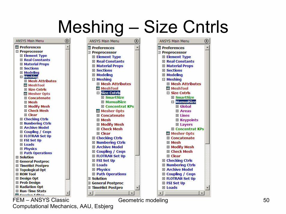
Meshing – Size Cntrls
Geometric modeling 51Computational Mechanics, AAU, EsbjergFEM – ANSYS Classic
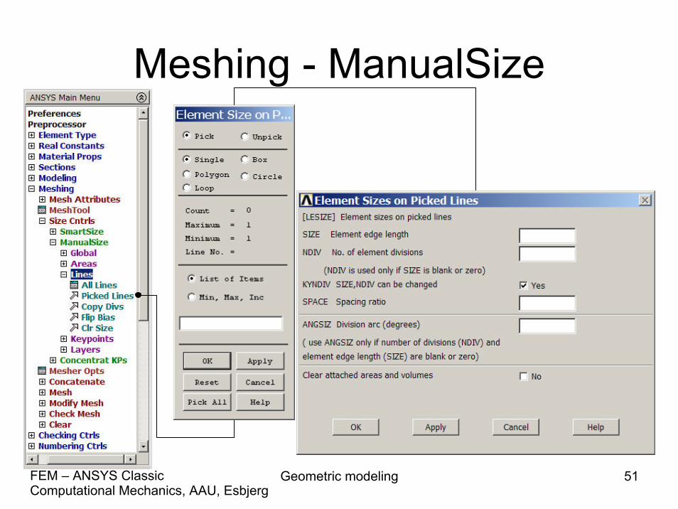
Meshing - ManualSize

Geometric modeling 52Computational Mechanics, AAU, EsbjergFEM – ANSYS Classic
Meshing - Lines
Geometric modeling 53Computational Mechanics, AAU, EsbjergFEM – ANSYS Classic
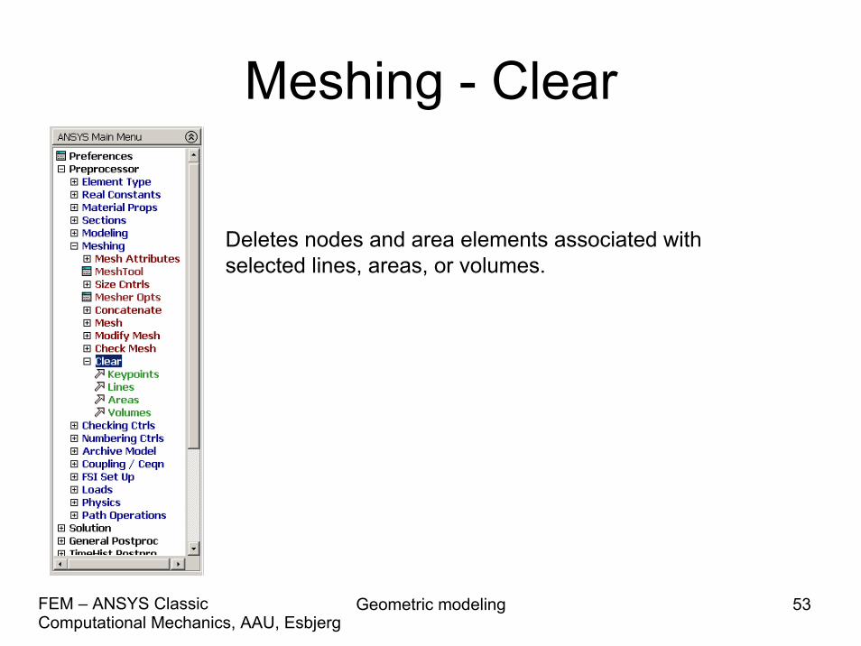
Meshing - Clear
Deletes nodes and area elements associated with selected lines, areas, or volumes.


![Introduction - Aalborg Universitethomes.civil.aau.dk/shl/ansysc/fem-nonlinear-introduction.pdf · • [ANSYS] ANSYS 10.0 Documentation (installed with ANSYS): – Basic Analysis Procedures](https://static.fdocuments.net/doc/165x107/608b42231337ee1469269f09/introduction-aalborg-a-ansys-ansys-100-documentation-installed-with-ansys.jpg)


