
Geospatial Technologies In the EAST Lab –GPS Technology –Intergraph GeoMedia GIS –ESRI GIS.
Upload
nguyennhanCategory
view
233download
0
i Customer Support Document Oct 2013
The leading provider of aerial imagery, remote sensing and geospatial solutions
Customer Support Document
BlomURBEX™ Geomedia Plug-in
User Manual
v. 4.0.1

Revision History
ii Customer Support Document Oct 2013
REVISION HISTORY
Revision Date Reason
1.0 December 2010 Document for release 2.5.0
2.0 November 2011 Document for release 3.0.0
3.0 October 2013 Document for release 4.0.0. Support for BlomSHOT
4.0 March 2014 Document for release 4.0.1
Contents
iii Customer Support Document Oct 2013
CONTENTS
1 INTRODUCTION .............................................................................................................. 1
2 SYSTEM REQUIREMENTS ................................................................................................. 2
3 Installing BlomURBEX plug-in for Geomedia .................................................................... 3
4 Starting with BlomURBEX plug-in for Geomedia .............................................................. 4
4.1 Setup the BlomURBEX Viewer plug-in in Geomedia .......................................................................4
4.2 Adding Data Sources ......................................................................................................................5
Adding BlomURBEXTM
as a Data Source .................................................................................................................. 5
Adding BlomSHOTTM
as a Data Source .................................................................................................................... 6
Adding Blom Library as a Data Source .................................................................................................................... 7 4.3 Manage the list of Datasources .....................................................................................................9
4.4 Setup the BlomURBEX Viewer basic options ..................................................................................9
4.5 Changing language interface .......................................................................................................13
4.6 Changing layout ...........................................................................................................................13
5 Viewing BlomURBEX images ......................................................................................... 15
5.1 Selecting location in Geomedia ....................................................................................................15
5.2 Introducing known coordinates in BlomURBEX Viewer ................................................................15
5.3 Panning images ............................................................................................................................16
5.4 Magnifying images .......................................................................................................................16
Zooming with the zoom bar in one view ............................................................................................................... 16
Zooming in or out with the mouse wheel in one view .......................................................................................... 17
Zooming to a extent in one view........................................................................................................................... 17 5.5 Changing views ............................................................................................................................17
5.6 The “intelligent” behavior ............................................................................................................18
5.7 Changing basemap ortho image ..................................................................................................19
5.8 Showing the visible and total extension in Geomedia ..................................................................20
5.9 Synchronizing views .....................................................................................................................21
5.10 Seeing historical images from different years ..............................................................................22
6 Obtaining image information ........................................................................................ 23
7 Using the measurement tools ....................................................................................... 25
7.1 Changing units of measure...........................................................................................................25
7.2 Viewing the coordinates of a location ..........................................................................................25
7.3 Measuring squared perimeter or distance ...................................................................................26
7.4 Measuring ground length .............................................................................................................27
7.5 Measuring bearing .......................................................................................................................27
7.6 Measuring area ............................................................................................................................28
7.7 Measuring height .........................................................................................................................29
7.8 Measuring elevation ....................................................................................................................30

Contents
iv
Customer Support Document Oct 2013
7.9 Measuring facade area ................................................................................................................30
7.10 Measuring diagonal length ..........................................................................................................31
7.11 Clearing measurements ...............................................................................................................32
8 Printing images ............................................................................................................. 33
8.1 Printing images ............................................................................................................................33
8.2 Changing print settings ................................................................................................................33
8.3 Page setup ....................................................................................................................................34
8.4 Print preview ................................................................................................................................34
9 Exporting images .......................................................................................................... 36
9.1 Exporting all visible views .............................................................................................................36
9.2 Projection of the extracted ortho images .....................................................................................36
10 Saving measurements ................................................................................................... 37
10.1 Setting measurement savings ......................................................................................................37
10.2 Starting and stopping save sessions .............................................................................................38
10.3 Procedure for saving measurements ............................................................................................39
11 Overlaying tile raster data............................................................................................. 41
11.1 Activating and deactivating tiled raster overlays .........................................................................41
12 Overlaying vector data .................................................................................................. 43
12.1 Activating and deactivating vector overlays ................................................................................43
12.2 Refreshing vector overlays ...........................................................................................................43
12.3 Overlay and performance considerations ....................................................................................43
12.4 Symbology limitations ..................................................................................................................44
13 Uninstalling BlomURBEX plug-in for Geomedia .............................................................. 45
14 Troubleshooting ........................................................................................................... 45
14.1 Log files ........................................................................................................................................45
15 Frequently Asked Questions ......................................................................................... 45
16 Appendix A: how to add new projections ...................................................................... 47
17 Appendix B: how to improve interface translation ......................................................... 47
BlomURBEX™ Geomedia Plug-in
1
Customer Support Document Oct 2013
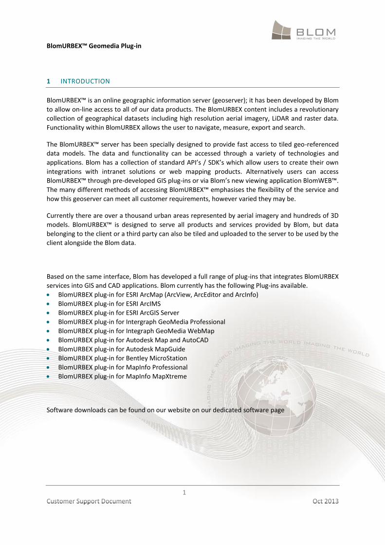
1 INTRODUCTION
BlomURBEX™ is an online geographic information server (geoserver); it has been developed by Blom
to allow on-line access to all of our data products. The BlomURBEX content includes a revolutionary
collection of geographical datasets including high resolution aerial imagery, LiDAR and raster data.
Functionality within BlomURBEX allows the user to navigate, measure, export and search.
The BlomURBEX™ server has been specially designed to provide fast access to tiled geo-referenced
data models. The data and functionality can be accessed through a variety of technologies and
applications. Blom has a collection of standard API’s / SDK’s which allow users to create their own
integrations with intranet solutions or web mapping products. Alternatively users can access
BlomURBEX™ through pre-developed GIS plug-ins or via Blom’s new viewing application BlomWEB™.
The many different methods of accessing BlomURBEX™ emphasises the flexibility of the service and
how this geoserver can meet all customer requirements, however varied they may be.
Currently there are over a thousand urban areas represented by aerial imagery and hundreds of 3D
models. BlomURBEX™ is designed to serve all products and services provided by Blom, but data
belonging to the client or a third party can also be tiled and uploaded to the server to be used by the
client alongside the Blom data.
Based on the same interface, Blom has developed a full range of plug-ins that integrates BlomURBEX
services into GIS and CAD applications. Blom currently has the following Plug-ins available.
BlomURBEX plug-in for ESRI ArcMap (ArcView, ArcEditor and ArcInfo)
BlomURBEX plug-in for ESRI ArcIMS
BlomURBEX plug-in for ESRI ArcGIS Server
BlomURBEX plug-in for Intergraph GeoMedia Professional
BlomURBEX plug-in for Integraph GeoMedia WebMap
BlomURBEX plug-in for Autodesk Map and AutoCAD
BlomURBEX plug-in for Autodesk MapGuide
BlomURBEX plug-in for Bentley MicroStation
BlomURBEX plug-in for MapInfo Professional
BlomURBEX plug-in for MapInfo MapXtreme
Software downloads can be found on our website on our dedicated software page
BlomURBEX™ Geomedia Plug-in
2
Customer Support Document Oct 2013
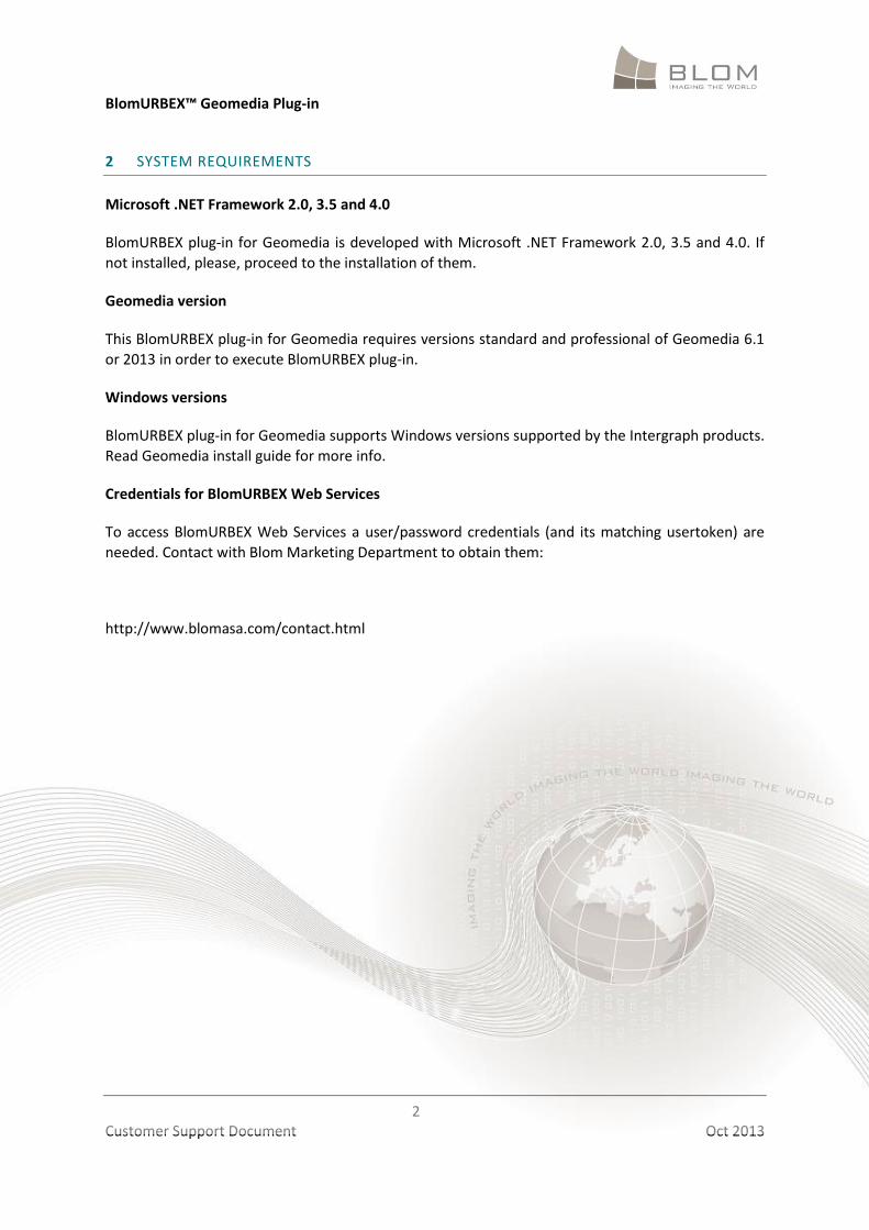
2 SYSTEM REQUIREMENTS
Microsoft .NET Framework 2.0, 3.5 and 4.0
BlomURBEX plug-in for Geomedia is developed with Microsoft .NET Framework 2.0, 3.5 and 4.0. If
not installed, please, proceed to the installation of them.
Geomedia version
This BlomURBEX plug-in for Geomedia requires versions standard and professional of Geomedia 6.1
or 2013 in order to execute BlomURBEX plug-in.
Windows versions
BlomURBEX plug-in for Geomedia supports Windows versions supported by the Intergraph products.
Read Geomedia install guide for more info.
Credentials for BlomURBEX Web Services
To access BlomURBEX Web Services a user/password credentials (and its matching usertoken) are
needed. Contact with Blom Marketing Department to obtain them:
http://www.blomasa.com/contact.html

BlomURBEX™ Geomedia Plug-in
3
Customer Support Document Oct 2013
3 INSTALLING BLOMURBEX PLUG-IN FOR GEOMEDIA
To install folow this steps: 1. Ensure you are logged onto your computer with Administrator privileges. 2. Close all programs. 3. If Plug-in is being installed for the first time then, ensure that GeoMedia has been run at least
once. 4. Uninstall previous “BlomURBEX plug-in” versions for any GIS or CAD package that could be
installed. Older “BlomURBEX plug-ins” cannot coexist with current version. If any other plug-in is installed for other GIS or CAD package, upgrade the plug-in also to last version.
5. Run setup.exe installer. Be careful to not run the MSI installer because this installer does not check if dependencies are already installed.
6. If Microsoft Interop Forms is not installed a dialog will appear to perform its installation. Click in Accept to accept the license agreement and continue. This software from Microsoft is an add-in to the .NET Framework that improves ActiveX / .NET interoperability.
7. Wait until Microsoft Interop Forms install completes. 8. The BlomURBEX plug-in for GeoMedia Setup Wizard will lead you through all stages of the setup
process. 9. Click Next > to begin installation. 10. The next screen displays the license agreement. Please read this and if you accept the terms
select the “I Agree” radio button. Click Next > to continue. 11. Click Browse to change the destination folder. Click “Disc cost” to confirm that there is enough
space to install. Select in the radio buttons if BlomURBEX plug-in for GeoMedia will be available to all users or just you in your computer. Click Next > to continue.
12. Click Next > to start installation. 13. Finally click Finish to close installation wizard.
BlomURBEX™ Geomedia Plug-in
4
Customer Support Document Oct 2013
4 STARTING WITH BLOMURBEX PLUG-IN FOR GEOMEDIA
4.1 Setup the BlomURBEX Viewer plug-in in Geomedia
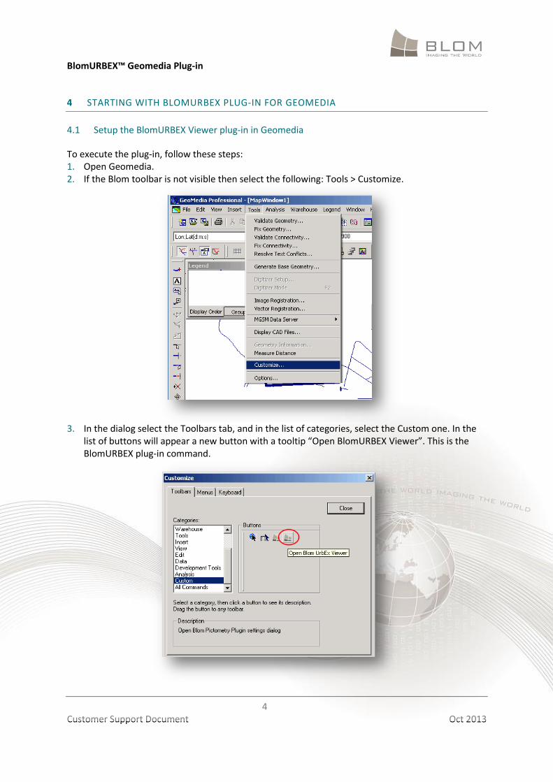
To execute the plug-in, follow these steps: 1. Open Geomedia. 2. If the Blom toolbar is not visible then select the following: Tools > Customize.
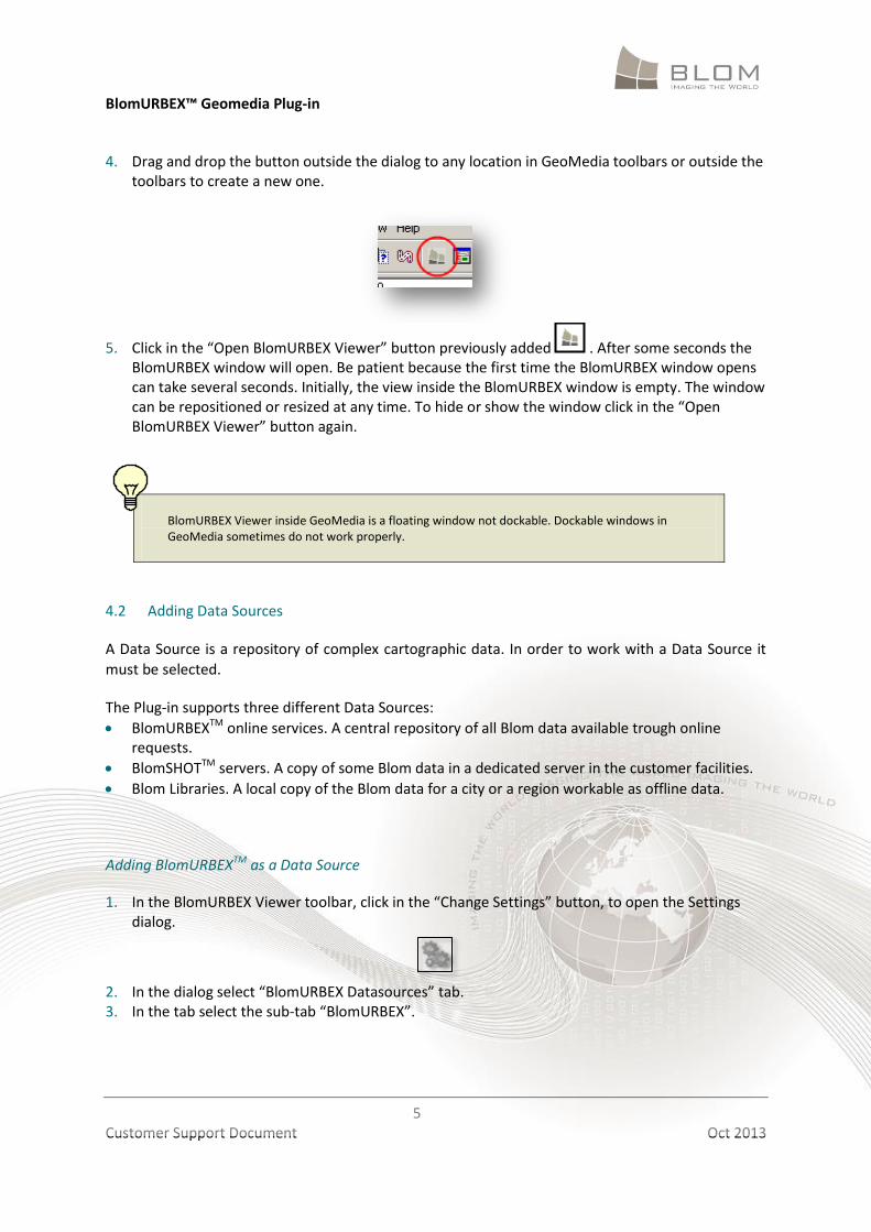
3. In the dialog select the Toolbars tab, and in the list of categories, select the Custom one. In the
list of buttons will appear a new button with a tooltip “Open BlomURBEX Viewer”. This is the BlomURBEX plug-in command.
BlomURBEX™ Geomedia Plug-in
5
Customer Support Document Oct 2013
4. Drag and drop the button outside the dialog to any location in GeoMedia toolbars or outside the toolbars to create a new one.
5. Click in the “Open BlomURBEX Viewer” button previously added . After some seconds the BlomURBEX window will open. Be patient because the first time the BlomURBEX window opens can take several seconds. Initially, the view inside the BlomURBEX window is empty. The window can be repositioned or resized at any time. To hide or show the window click in the “Open BlomURBEX Viewer” button again.
BlomURBEX Viewer inside GeoMedia is a floating window not dockable. Dockable windows in GeoMedia sometimes do not work properly.
4.2 Adding Data Sources
A Data Source is a repository of complex cartographic data. In order to work with a Data Source it
must be selected.
The Plug-in supports three different Data Sources:
BlomURBEXTM online services. A central repository of all Blom data available trough online requests.
BlomSHOTTM servers. A copy of some Blom data in a dedicated server in the customer facilities.
Blom Libraries. A local copy of the Blom data for a city or a region workable as offline data.
Adding BlomURBEXTM as a Data Source
1. In the BlomURBEX Viewer toolbar, click in the “Change Settings” button, to open the Settings dialog.
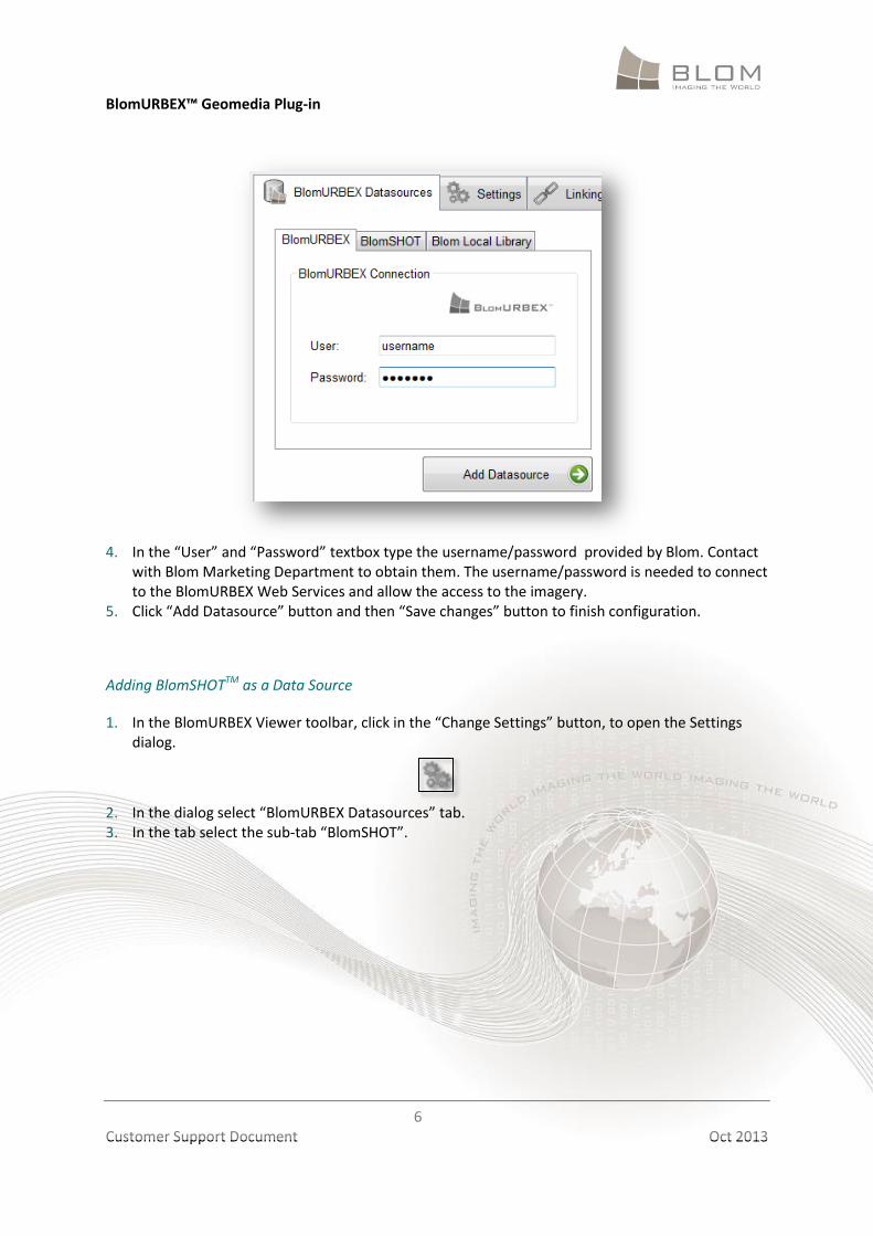
2. In the dialog select “BlomURBEX Datasources” tab. 3. In the tab select the sub-tab “BlomURBEX”.
BlomURBEX™ Geomedia Plug-in
6
Customer Support Document Oct 2013
4. In the “User” and “Password” textbox type the username/password provided by Blom. Contact
with Blom Marketing Department to obtain them. The username/password is needed to connect to the BlomURBEX Web Services and allow the access to the imagery.
5. Click “Add Datasource” button and then “Save changes” button to finish configuration.
Adding BlomSHOTTM as a Data Source
1. In the BlomURBEX Viewer toolbar, click in the “Change Settings” button, to open the Settings dialog.
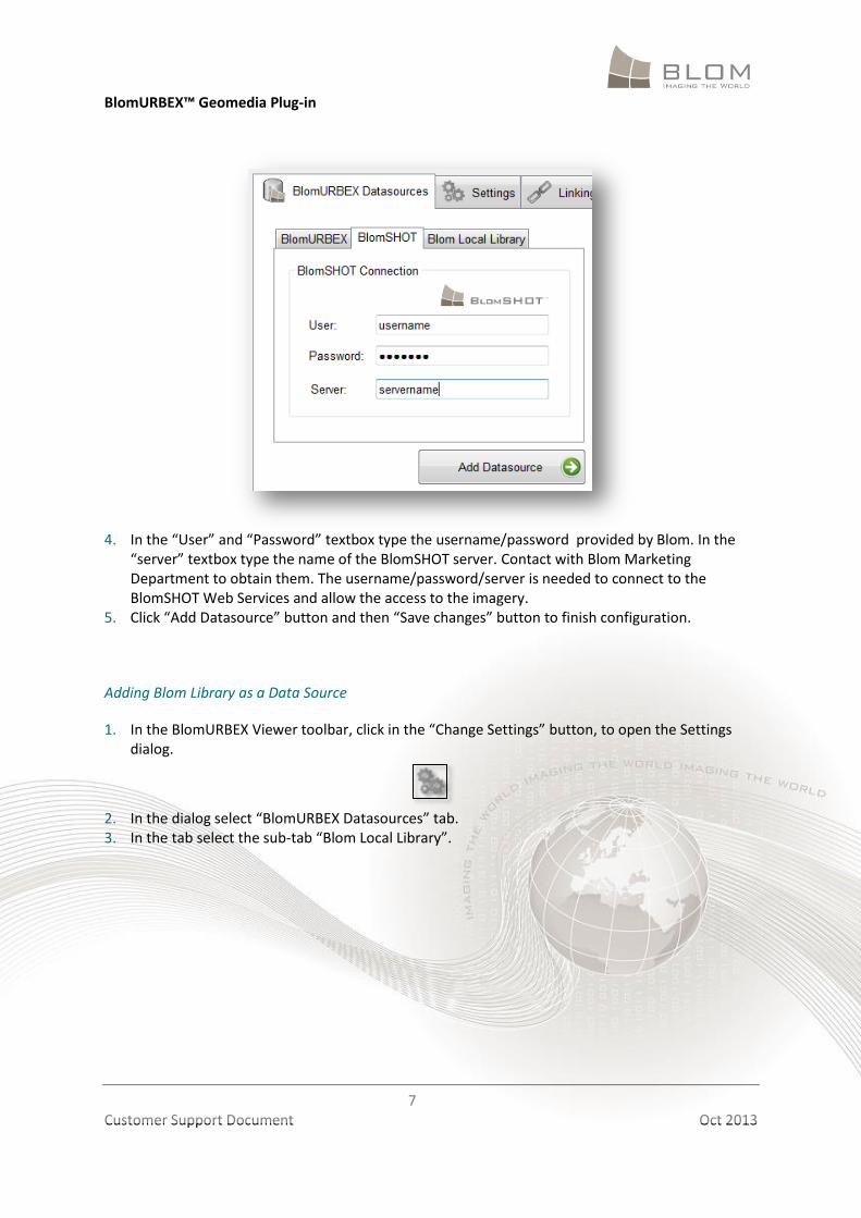
2. In the dialog select “BlomURBEX Datasources” tab. 3. In the tab select the sub-tab “BlomSHOT”.
BlomURBEX™ Geomedia Plug-in
7
Customer Support Document Oct 2013
4. In the “User” and “Password” textbox type the username/password provided by Blom. In the
“server” textbox type the name of the BlomSHOT server. Contact with Blom Marketing Department to obtain them. The username/password/server is needed to connect to the BlomSHOT Web Services and allow the access to the imagery.
5. Click “Add Datasource” button and then “Save changes” button to finish configuration.
Adding Blom Library as a Data Source
1. In the BlomURBEX Viewer toolbar, click in the “Change Settings” button, to open the Settings dialog.
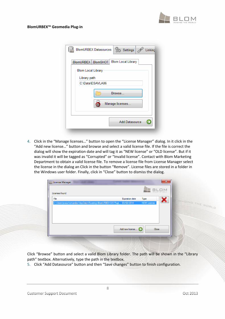
2. In the dialog select “BlomURBEX Datasources” tab. 3. In the tab select the sub-tab “Blom Local Library”.
BlomURBEX™ Geomedia Plug-in
8
Customer Support Document Oct 2013
4. Click in the “Manage licenses…” button to open the “License Manager” dialog. In it click in the
“Add new license…” button and browse and select a valid license file. If the file is correct the dialog will show the expiration date and will tag it as “NEW license” or “OLD license”. But if it was invalid it will be tagged as “Corrupted” or “Invalid license”. Contact with Blom Marketing Department to obtain a valid license file. To remove a license file from License Manager select the license in the dialog an Click in the button “Remove”. License files are stored in a folder in the Windows user folder. Finally, click in “Close” button to dismiss the dialog.
Click “Browse” button and select a valid Blom Library folder. The path will be shown in the “Library
path” textbox. Alternatively, type the path in the textbox. 5. Click “Add Datasource” button and then “Save changes” button to finish configuration.
BlomURBEX™ Geomedia Plug-in
9
Customer Support Document Oct 2013
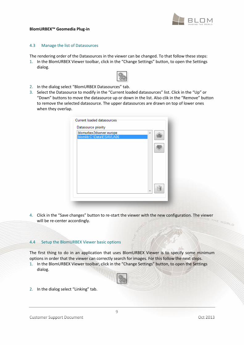
4.3 Manage the list of Datasources
The rendering order of the Datasources in the viewer can be changed. To that follow these steps: 1. In the BlomURBEX Viewer toolbar, click in the “Change Settings” button, to open the Settings
dialog.
2. In the dialog select “BlomURBEX Datasources” tab. 3. Select the Datasource to modify in the “Current loaded datasources” list. Click in the “Up” or
“Down” buttons to move the datasource up or down in the list. Also clik in the “Remove” button to remove the selected datasource. The upper datasources are drawn on top of lower ones when they overlap.
4. Click in the “Save changes” button to re-start the viewer with the new configuration. The viewer
will be re-center accordingly.
4.4 Setup the BlomURBEX Viewer basic options
The first thing to do in an application that uses BlomURBEX Viewer is to specify some minimum
options in order that the viewer can correctly search for images. For this follow the next steps. 1. In the BlomURBEX Viewer toolbar, click in the “Change Settings” button, to open the Settings
dialog.
2. In the dialog select “Linking” tab.
BlomURBEX™ Geomedia Plug-in
10
Customer Support Document Oct 2013
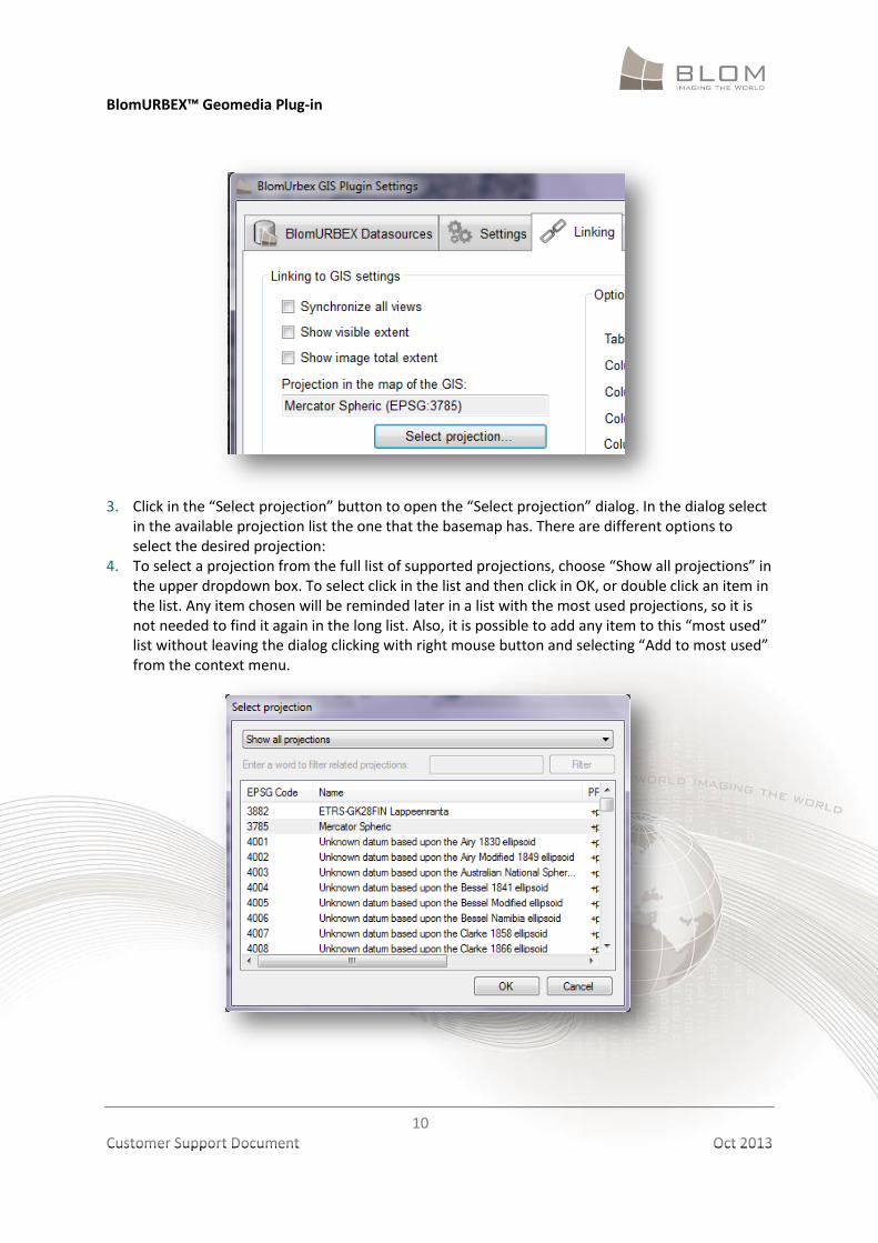
3. Click in the “Select projection” button to open the “Select projection” dialog. In the dialog select
in the available projection list the one that the basemap has. There are different options to select the desired projection:
4. To select a projection from the full list of supported projections, choose “Show all projections” in the upper dropdown box. To select click in the list and then click in OK, or double click an item in the list. Any item chosen will be reminded later in a list with the most used projections, so it is not needed to find it again in the long list. Also, it is possible to add any item to this “most used” list without leaving the dialog clicking with right mouse button and selecting “Add to most used” from the context menu.
BlomURBEX™ Geomedia Plug-in
11
Customer Support Document Oct 2013
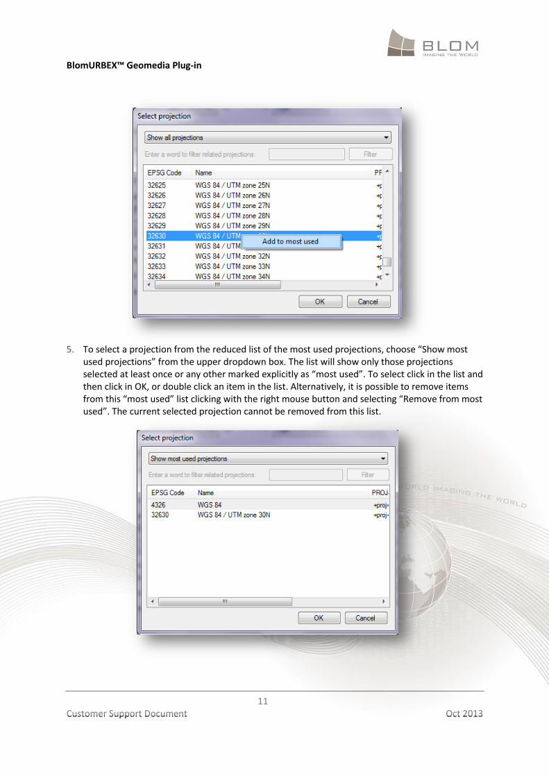
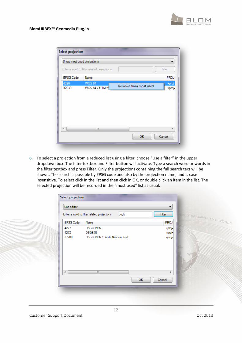
5. To select a projection from the reduced list of the most used projections, choose “Show most
used projections” from the upper dropdown box. The list will show only those projections selected at least once or any other marked explicitly as “most used”. To select click in the list and then click in OK, or double click an item in the list. Alternatively, it is possible to remove items from this “most used” list clicking with the right mouse button and selecting “Remove from most used”. The current selected projection cannot be removed from this list.
BlomURBEX™ Geomedia Plug-in
12
Customer Support Document Oct 2013
6. To select a projection from a reduced list using a filter, choose “Use a filter” in the upper
dropdown box. The filter textbox and Filter button will activate. Type a search word or words in the filter textbox and press Filter. Only the projections containing the full search text will be shown. The search is possible by EPSG code and also by the projection name, and is case insensitive. To select click in the list and then click in OK, or double click an item in the list. The selected projection will be recorded in the “most used” list as usual.
BlomURBEX™ Geomedia Plug-in
13
Customer Support Document Oct 2013
7. Click in the “Save changes” button to finish the configuration.
Settings do not persist, if the Plug-in is reinstalled. We need to set the settings again in case of re-installation.
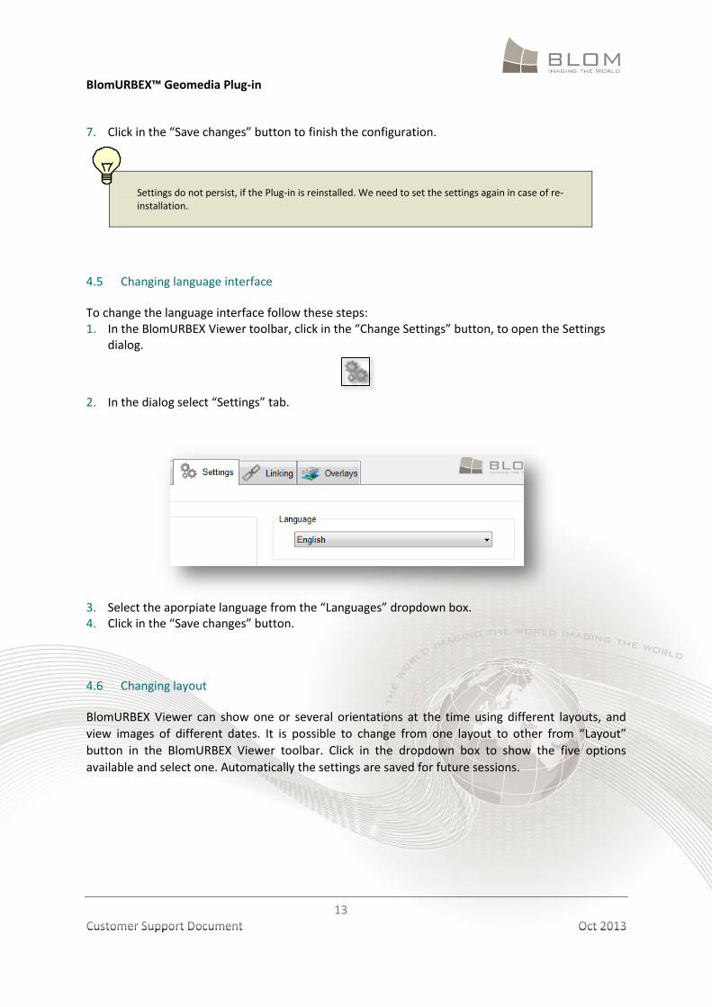
4.5 Changing language interface
To change the language interface follow these steps: 1. In the BlomURBEX Viewer toolbar, click in the “Change Settings” button, to open the Settings
dialog.
2. In the dialog select “Settings” tab.
3. Select the aporpiate language from the “Languages” dropdown box. 4. Click in the “Save changes” button.
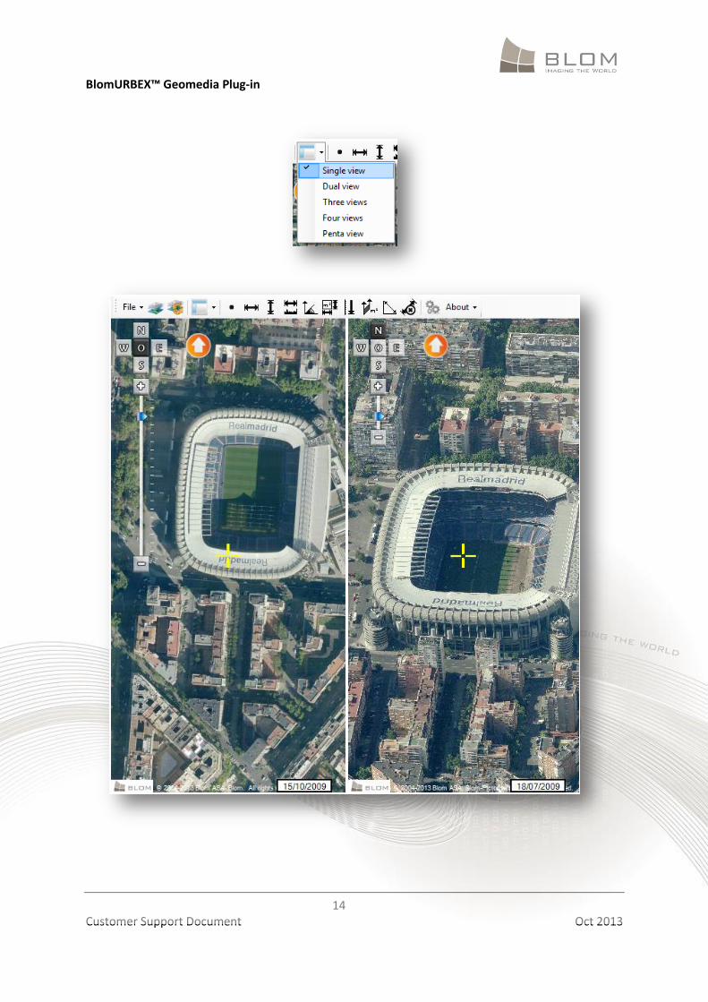
4.6 Changing layout
BlomURBEX Viewer can show one or several orientations at the time using different layouts, and
view images of different dates. It is possible to change from one layout to other from “Layout”
button in the BlomURBEX Viewer toolbar. Click in the dropdown box to show the five options
available and select one. Automatically the settings are saved for future sessions.
BlomURBEX™ Geomedia Plug-in
14
Customer Support Document Oct 2013
BlomURBEX™ Geomedia Plug-in
15
Customer Support Document Oct 2013
5 VIEWING BLOMURBEX IMAGES
The BlomURBEX Viewer is the window that shows BlomURBEX images. To open an image is needed
to select a location, either clicking in the basemap in Geomedia or introducing a known coordinates.
5.1 Selecting location in Geomedia
1. Open Geomedia with a basemap. 2. Open BlomURBEX Viewer if it is not, as explained previously. 3. Ensure that settings are correct, as previously indicated. 4. Resize and move application windows so they can be seen comfortably. 5. Open any map data in Geomedia. The data can use any projection if it is in the EPSG list in the
BlomURBEX Viewer options. It is only needed to know the projection and to indicate this projection in the BlomURBEX Viewer settings dialog.
Remember when using different drawing files in Geomedia with different projections to modify the options in BlomURBEX Viewer matching the active one.
6. Ensure that the button “BlomURBEX” is selected . 7. Click in any location in the map. 8. After some seconds BlomURBEX Viewer will open the best BlomURBEX images for that location,
in all the orientations selected in the BlomURBEX Viewer layout. The images are centered in the selected point and show a crosshair. If no image appears consider if your BlomURBEX user permissions do not allow seeing images for that location.
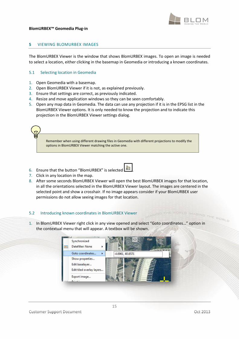
5.2 Introducing known coordinates in BlomURBEX Viewer
1. In BlomURBEX Viewer right click in any view opened and select “Goto coordinates…” option in the contextual menu that will appear. A textbox will be shown.
BlomURBEX™ Geomedia Plug-in
16
Customer Support Document Oct 2013
2. Introduce a correct longitude or X and latitude or Y coordinates, separating both value with comma. The projection for these coordinates must be the same of the current projection for the drawing in Geomedia, the same projection that was saved in the Settings dialog.
3. Click OK. 4. After some seconds BlomURBEX Viewer will open the best BlomURBEX images for that location,
in all the orientations selected in the BlomURBEX Viewer layout. The images are centered in the selected point and show a crosshair. If no image appears consider if your user permissions do not allow seeing images for that location.
5.3 Panning images
“Panning” is the default behaviour of the display when no tool is selected. 1. In BlomURBEX Viewer unselect any tool in the toolbar. 2. Click and hold the left mouse button in the view to pan. 3. Drag the image up, down, left, or right within the view, and finally release mouse.
5.4 Magnifying images
It is possible to zoom in for more detail or zoom out for more context information. Simply change
the image’s magnification by using the zoom buttons inside the views.
Zooming with the zoom bar in one view
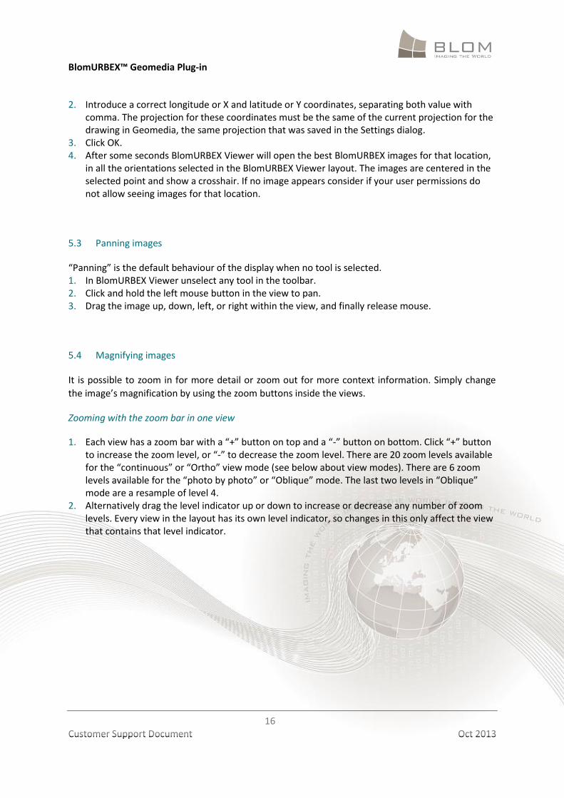
1. Each view has a zoom bar with a “+” button on top and a “-” button on bottom. Click “+” button to increase the zoom level, or “-” to decrease the zoom level. There are 20 zoom levels available for the “continuous” or “Ortho” view mode (see below about view modes). There are 6 zoom levels available for the “photo by photo” or “Oblique” mode. The last two levels in “Oblique” mode are a resample of level 4.
2. Alternatively drag the level indicator up or down to increase or decrease any number of zoom levels. Every view in the layout has its own level indicator, so changes in this only affect the view that contains that level indicator.
BlomURBEX™ Geomedia Plug-in
17
Customer Support Document Oct 2013
Zooming in or out with the mouse wheel in one view
Move the mouse wheel frontwards or backwards to zoom in or out in just one view.
Zooming to a extent in one view
1. Unselect any tool selected in the toolbar so the “Pan” default tool activates. 2. Press SHIFT key in keyboard. 3. Click with left mouse button in any view and hold pressed. Drag to draw a rectangle. A rectangle
appears showing the extent selected. Release button at the ending corner. 4. Map centers and zoom to the best level zoom that contains the selected extent. This action only
affects the view used.
5.5 Changing views
Initially each view in the layout has set an orientation, but it is possible to modify this selecting
orientations orientation selector. In fact, it is possible to have the same image several times. For
example, it is possible to use the dual view to have two times the same ortho image opened. It can
be useful to have a master – detail view to study two distant buildings at the same time that are in
the same photo. Each time an orientation is changed in a view this setting is saved so it will be used
until changed again.
There are two types of view modes: “Ortho”, that shows the images in a continuous mode, and
“Oblique”, that shows images one by one. In both modes it is possible to do “Pan” in the map
endlessly. In the Oblique mode a new image is loaded in a seamless way when “panning” reaches
the border of the current loaded image.
BlomURBEX™ Geomedia Plug-in
18
Customer Support Document Oct 2013
Oblique imagery shown in a “continuous” or “Ortho” mode may suffer some distortion due to the irregularities of the terrain model that affects the ortho-rectification process. In flatter terrains the distortion is lesser.
Tools are unselected when the view mode changes. Remember to select again the tool if using one when the mode is changed.
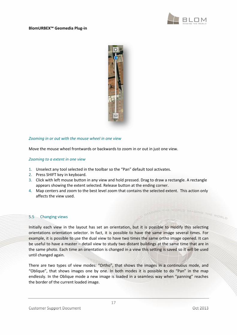
There are five types of orientations: “Ortho” orientation, that shows the image as an ortho-photo;
“North”, that shows the image looking from south to north; “South”, from north to south; “East”,
from west to east; and “West”, from east to west. To change the orientation click in the “O”, “N”,
“S”, “E” or “W” buttons in the upper left control to activate the “Ortho”, “North”, “South”, “East”
and “West” orientations, respectively.
The size of each view in the layout can be changed through the use of splitter bars between the
views. Just move the mouse in the boundary of two views, and when the cursor changes, drag and
drop the splitter to change the size of the views. Each time the size is changed this setting is saved in
settings.
5.6 The “intelligent” behavior
At closer zoom levels, oblique rectified images show big distortion on the buildings, while at furthest
zoom levels they do not offer better information than the ortho images.
Each view in the BlomURBEX Viewer is configured in an “intelligent” way so that any request that
attempts to change the zoom level of the view will check if the view is displaying any orientation
other than Ortho, and in this case decide what set of images should be displayed: ortho, oblique
rectified or natural obliques.
BlomURBEX™ Geomedia Plug-in
19
Customer Support Document Oct 2013
5.7 Changing basemap ortho image
By default the ortho image shown as basemap is one from several images available in BlomURBEX
server. These images are visible are certain resolutions, and among them are theses images:
“satellite”, with low resolution of the data. This source data is available in the furthest zoom levels (1 to 13), and contains Blue Marble and Landsat 7 imagery.
“countryortho”, imagery covering a whole country (or a region). This source data is available in the medium zoom levels (13 to 19), and contains imagery from several providers and from Blom.
As can be seen at certain zoom levels different sources coexist. It is possible to change what layers
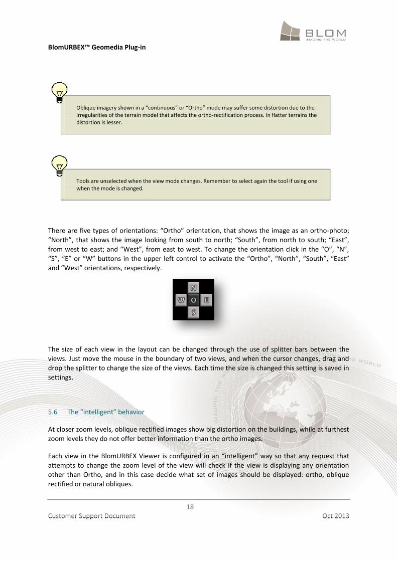
must be shown as baselayers. For that follow these steps: 1. Right click in any view and select “Edit baselayers…” option in the context menu. The “Configure
baselayers” dialog opens. 2. For load different baselayers instead of the default baselayers, uncheck the “Use default
baselayers” checkbox. This will enable the “Available baselayers” and “Selected baselayers” lists.
3. Select one or many layers in the “Available baselayers”. Depending on the user agreement with
Blom the layers should vary. Click in the “Add” button (>) to move that layers to the “Selected baselayers” list. To remove layers select them in the “Selected baselayers” list and click in the “Remove” button (<). Only layers in “Selected” list will be drawn.
BlomURBEX™ Geomedia Plug-in
20
Customer Support Document Oct 2013
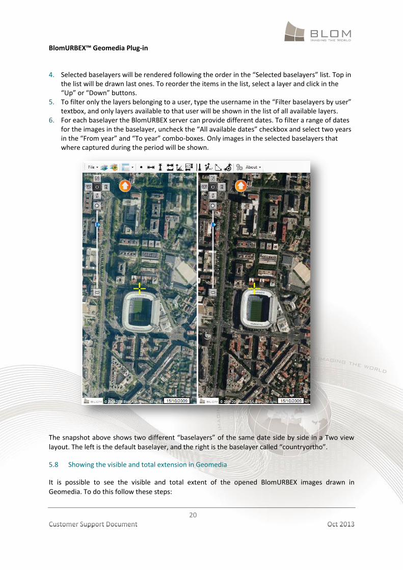
4. Selected baselayers will be rendered following the order in the “Selected baselayers” list. Top in the list will be drawn last ones. To reorder the items in the list, select a layer and click in the “Up” or “Down” buttons.
5. To filter only the layers belonging to a user, type the username in the “Filter baselayers by user” textbox, and only layers available to that user will be shown in the list of all available layers.
6. For each baselayer the BlomURBEX server can provide different dates. To filter a range of dates for the images in the baselayer, uncheck the “All available dates” checkbox and select two years in the “From year” and “To year” combo-boxes. Only images in the selected baselayers that where captured during the period will be shown.
The snapshot above shows two different “baselayers” of the same date side by side in a Two view
layout. The left is the default baselayer, and the right is the baselayer called “countryortho”.
5.8 Showing the visible and total extension in Geomedia
It is possible to see the visible and total extent of the opened BlomURBEX images drawn in
Geomedia. To do this follow these steps:
BlomURBEX™ Geomedia Plug-in
21
Customer Support Document Oct 2013
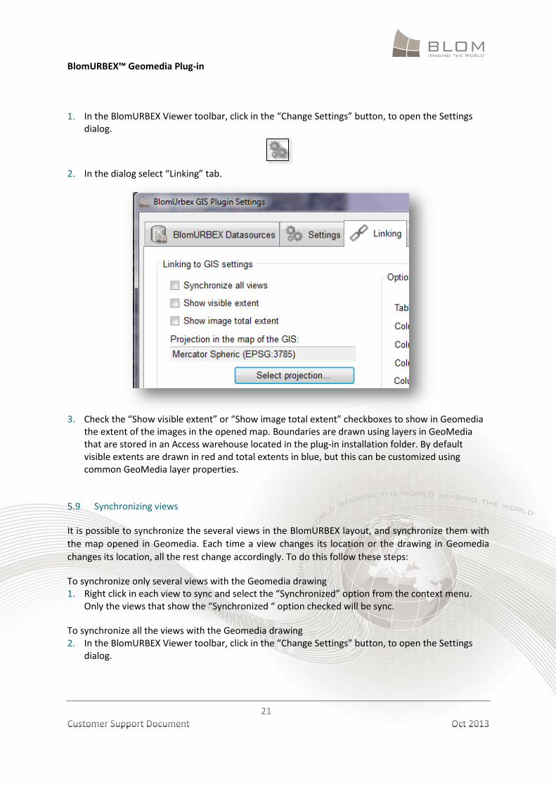
1. In the BlomURBEX Viewer toolbar, click in the “Change Settings” button, to open the Settings
dialog.
2. In the dialog select “Linking” tab.
3. Check the “Show visible extent” or “Show image total extent” checkboxes to show in Geomedia
the extent of the images in the opened map. Boundaries are drawn using layers in GeoMedia that are stored in an Access warehouse located in the plug-in installation folder. By default visible extents are drawn in red and total extents in blue, but this can be customized using common GeoMedia layer properties.
5.9 Synchronizing views
It is possible to synchronize the several views in the BlomURBEX layout, and synchronize them with
the map opened in Geomedia. Each time a view changes its location or the drawing in Geomedia
changes its location, all the rest change accordingly. To do this follow these steps:
To synchronize only several views with the Geomedia drawing 1. Right click in each view to sync and select the “Synchronized” option from the context menu.
Only the views that show the “Synchronized “ option checked will be sync.
To synchronize all the views with the Geomedia drawing 2. In the BlomURBEX Viewer toolbar, click in the “Change Settings” button, to open the Settings
dialog.
BlomURBEX™ Geomedia Plug-in
22
Customer Support Document Oct 2013
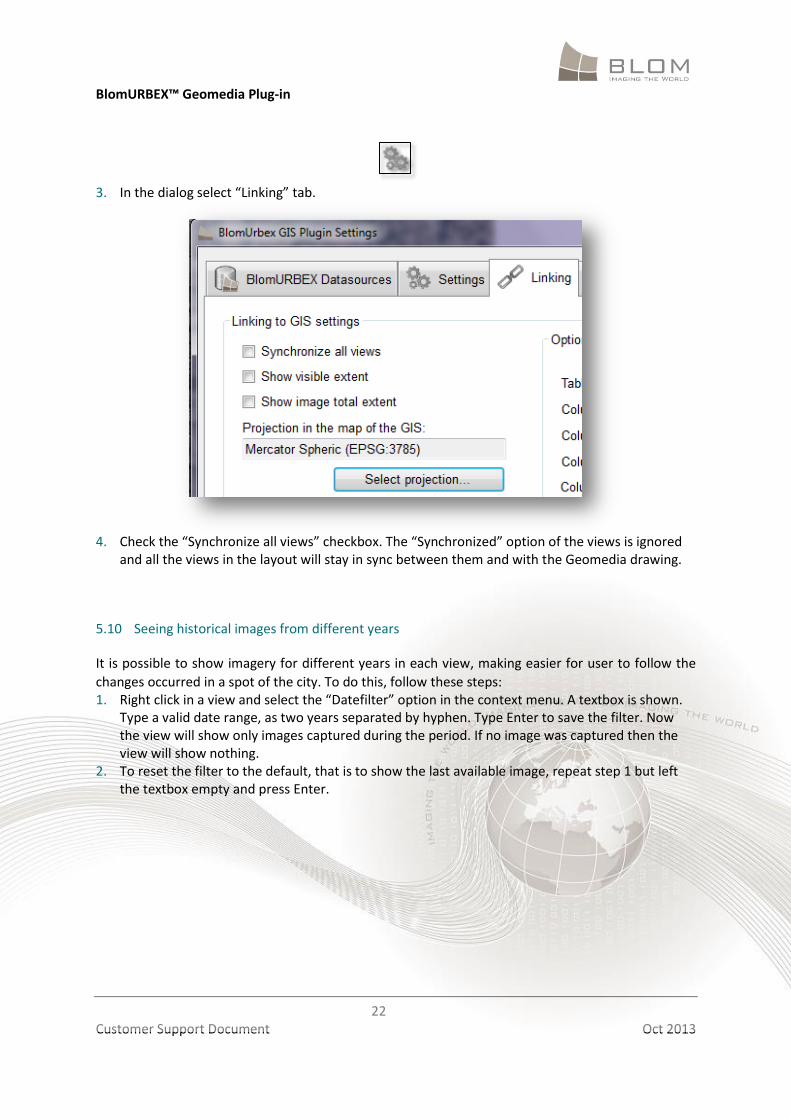
3. In the dialog select “Linking” tab.
4. Check the “Synchronize all views” checkbox. The “Synchronized” option of the views is ignored
and all the views in the layout will stay in sync between them and with the Geomedia drawing.
5.10 Seeing historical images from different years
It is possible to show imagery for different years in each view, making easier for user to follow the
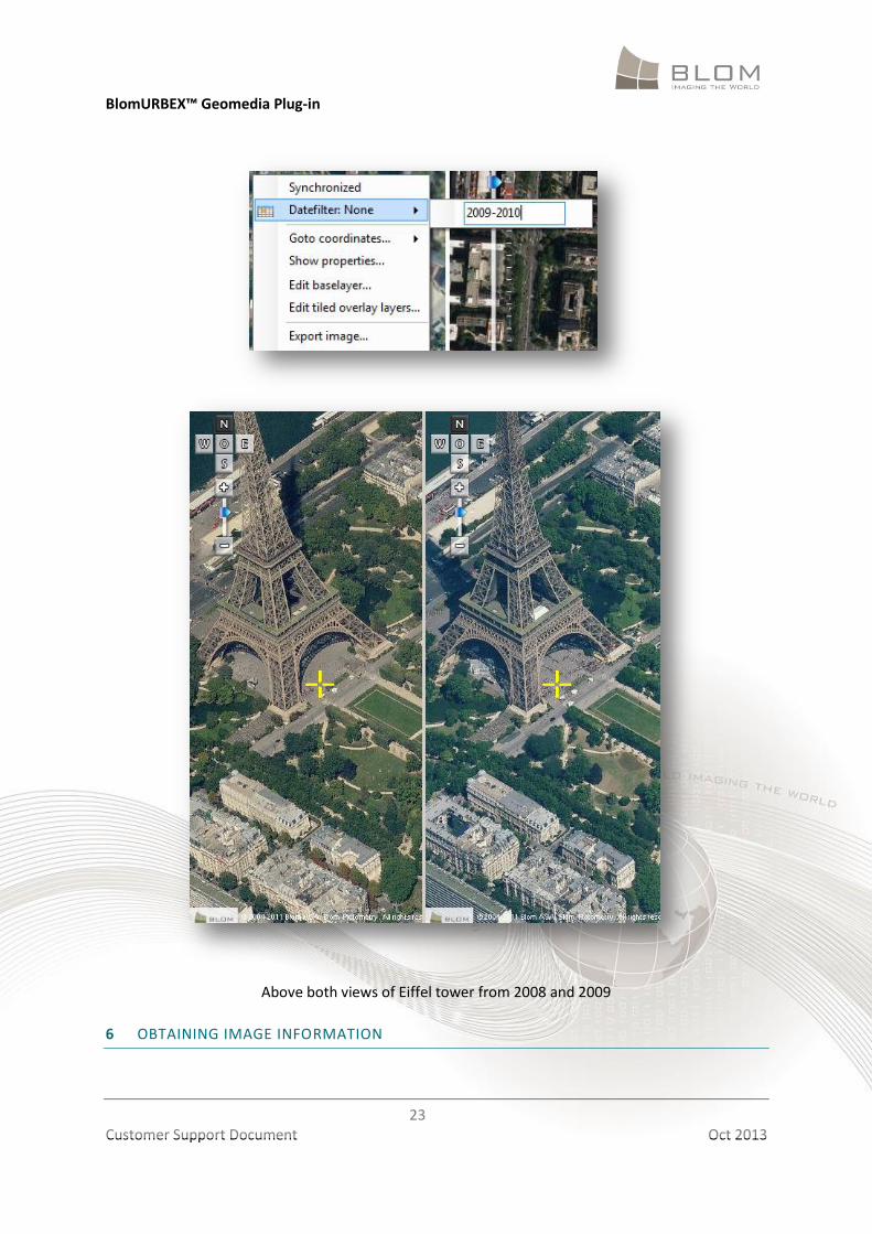
changes occurred in a spot of the city. To do this, follow these steps: 1. Right click in a view and select the “Datefilter” option in the context menu. A textbox is shown.
Type a valid date range, as two years separated by hyphen. Type Enter to save the filter. Now the view will show only images captured during the period. If no image was captured then the view will show nothing.
2. To reset the filter to the default, that is to show the last available image, repeat step 1 but left the textbox empty and press Enter.
BlomURBEX™ Geomedia Plug-in
23
Customer Support Document Oct 2013
Above both views of Eiffel tower from 2008 and 2009
6 OBTAINING IMAGE INFORMATION
BlomURBEX™ Geomedia Plug-in
24
Customer Support Document Oct 2013
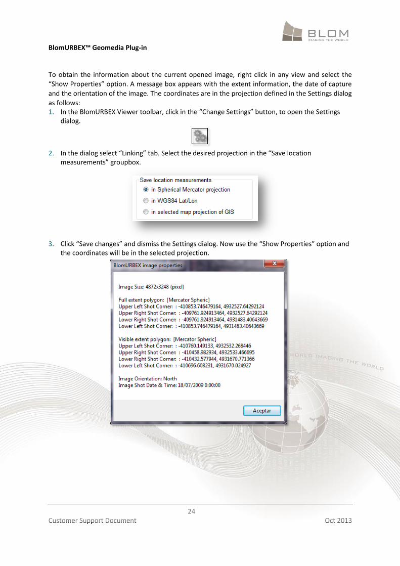
To obtain the information about the current opened image, right click in any view and select the
“Show Properties” option. A message box appears with the extent information, the date of capture
and the orientation of the image. The coordinates are in the projection defined in the Settings dialog
as follows: 1. In the BlomURBEX Viewer toolbar, click in the “Change Settings” button, to open the Settings
dialog.
2. In the dialog select “Linking” tab. Select the desired projection in the “Save location
measurements” groupbox.
3. Click “Save changes” and dismiss the Settings dialog. Now use the “Show Properties” option and
the coordinates will be in the selected projection.
BlomURBEX™ Geomedia Plug-in
25
Customer Support Document Oct 2013
7 USING THE MEASUREMENT TOOLS
BlomURBEX Viewer offers various tools for measuring features visible in images. For example, it is
possible to measure the distance between two points, the elevation of the terrain, building heights,
bearing, area, perimeter, the coordinates of a point, etc.
Before using the measurement tools, be sure that the unit of measure is set as desired.
7.1 Changing units of measure
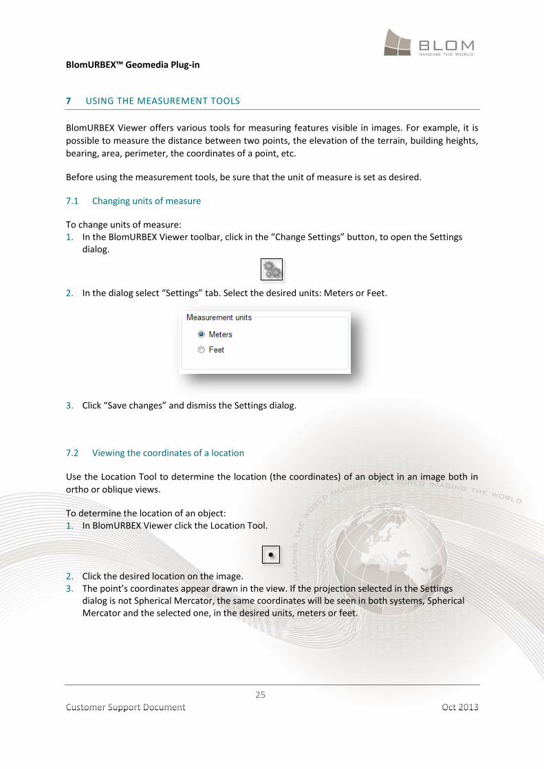
To change units of measure: 1. In the BlomURBEX Viewer toolbar, click in the “Change Settings” button, to open the Settings
dialog.
2. In the dialog select “Settings” tab. Select the desired units: Meters or Feet.
3. Click “Save changes” and dismiss the Settings dialog.
7.2 Viewing the coordinates of a location
Use the Location Tool to determine the location (the coordinates) of an object in an image both in
ortho or oblique views.
To determine the location of an object: 1. In BlomURBEX Viewer click the Location Tool.
2. Click the desired location on the image. 3. The point’s coordinates appear drawn in the view. If the projection selected in the Settings
dialog is not Spherical Mercator, the same coordinates will be seen in both systems, Spherical Mercator and the selected one, in the desired units, meters or feet.
BlomURBEX™ Geomedia Plug-in
26
Customer Support Document Oct 2013
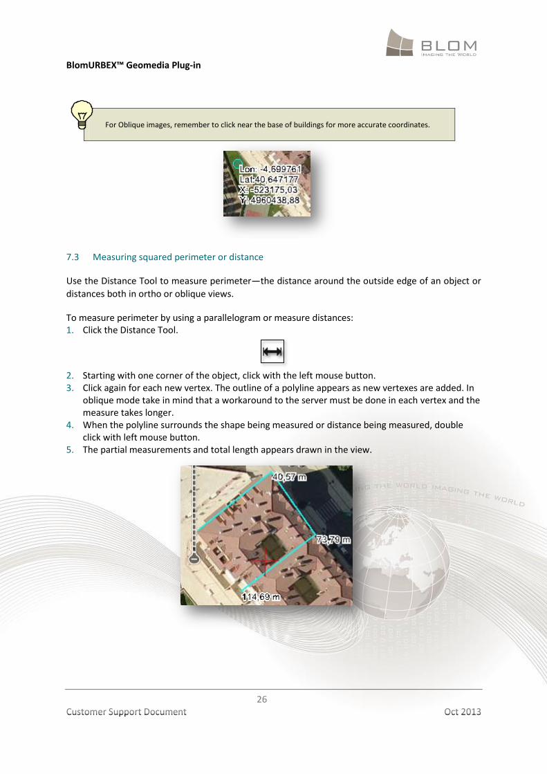
For Oblique images, remember to click near the base of buildings for more accurate coordinates.
7.3 Measuring squared perimeter or distance
Use the Distance Tool to measure perimeter—the distance around the outside edge of an object or
distances both in ortho or oblique views.
To measure perimeter by using a parallelogram or measure distances: 1. Click the Distance Tool.
2. Starting with one corner of the object, click with the left mouse button. 3. Click again for each new vertex. The outline of a polyline appears as new vertexes are added. In
oblique mode take in mind that a workaround to the server must be done in each vertex and the measure takes longer.
4. When the polyline surrounds the shape being measured or distance being measured, double click with left mouse button.
5. The partial measurements and total length appears drawn in the view.
BlomURBEX™ Geomedia Plug-in
27
Customer Support Document Oct 2013
7.4 Measuring ground length
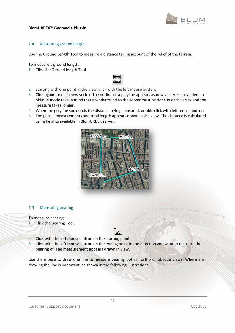
Use the Ground Length Tool to measure a distance taking account of the relief of the terrain.
To measure a ground length: 1. Click the Ground length Tool.
2. Starting with one point in the view, click with the left mouse button. 3. Click again for each new vertex. The outline of a polyline appears as new vertexes are added. In
oblique mode take in mind that a workaround to the server must be done in each vertex and the measure takes longer.
4. When the polyline surrounds the distance being measured, double click with left mouse button. 5. The partial measurements and total length appears drawn in the view. The distance is calculated
using heights available in BlomURBEX server.
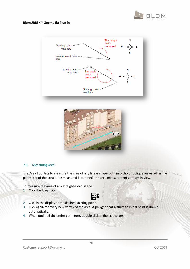
7.5 Measuring bearing
To measure bearing: 1. Click the Bearing Tool.
2. Click with the left mouse button on the starting point. 3. Click with the left mouse button on the ending point in the direction you want to measure the
bearing of. The measurement appears drawn in view.
Use the mouse to draw one line to measure bearing both in ortho or oblique views. Where start
drawing the line is important, as shown in the following illustrations:
BlomURBEX™ Geomedia Plug-in
28
Customer Support Document Oct 2013
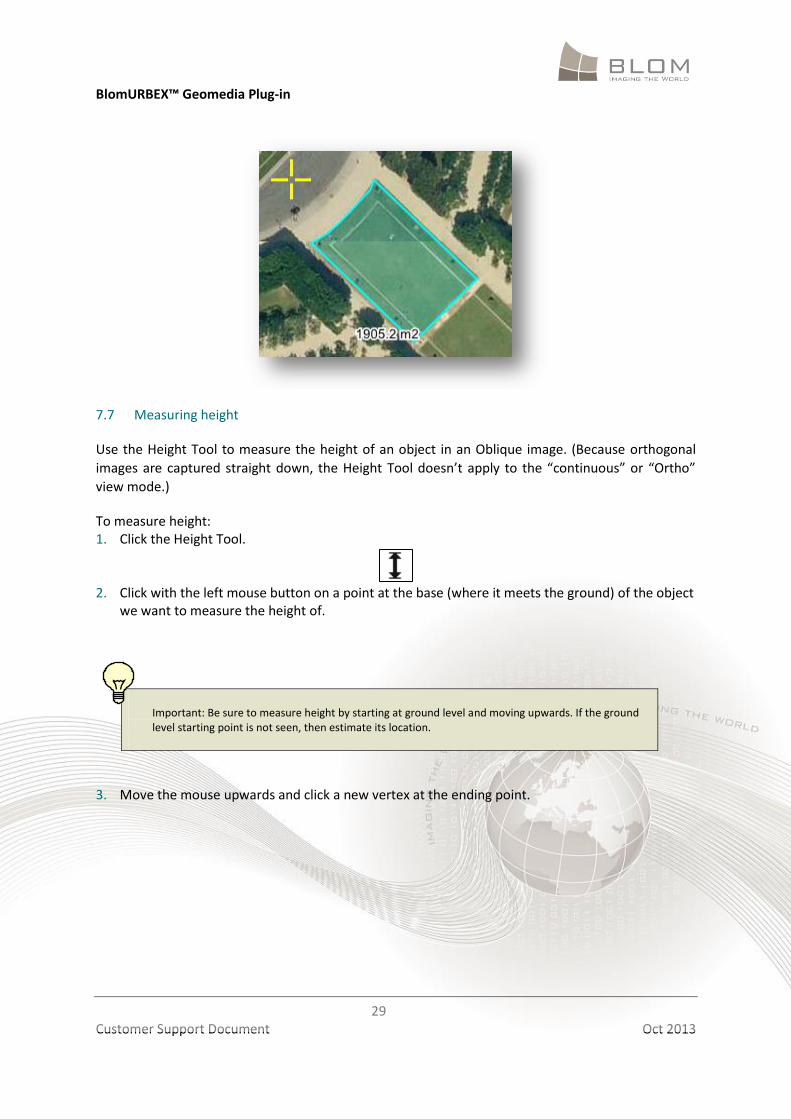
7.6 Measuring area
The Area Tool lets to measure the area of any linear shape both in ortho or oblique views. After the
perimeter of the area to be measured is outlined, the area measurement appears in view.
To measure the area of any straight-sided shape: 1. Click the Area Tool.
2. Click in the display at the desired starting point. 3. Click again for every new vertex of the area. A polygon that returns to initial point is drawn
automatically. 4. When outlined the entire perimeter, double click in the last vertex.
BlomURBEX™ Geomedia Plug-in
29
Customer Support Document Oct 2013
7.7 Measuring height
Use the Height Tool to measure the height of an object in an Oblique image. (Because orthogonal
images are captured straight down, the Height Tool doesn’t apply to the “continuous” or “Ortho”
view mode.)
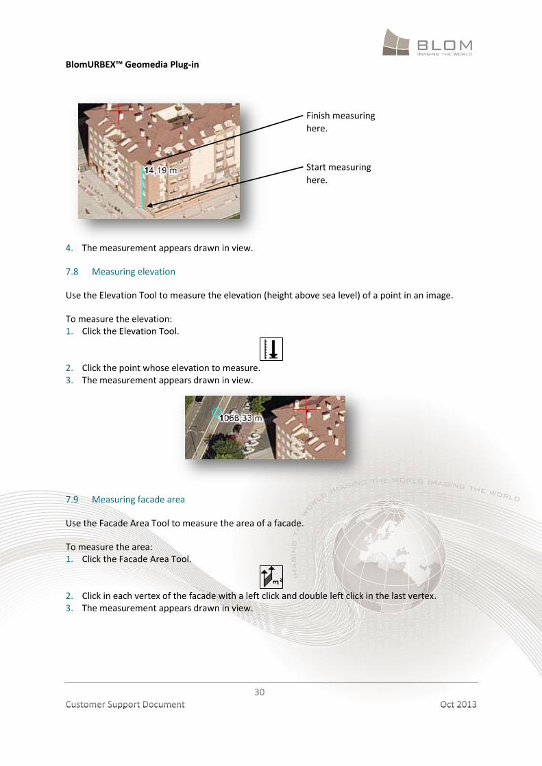
To measure height: 1. Click the Height Tool.
2. Click with the left mouse button on a point at the base (where it meets the ground) of the object
we want to measure the height of.
Important: Be sure to measure height by starting at ground level and moving upwards. If the ground level starting point is not seen, then estimate its location.
3. Move the mouse upwards and click a new vertex at the ending point.
BlomURBEX™ Geomedia Plug-in
30
Customer Support Document Oct 2013
4. The measurement appears drawn in view.
7.8 Measuring elevation
Use the Elevation Tool to measure the elevation (height above sea level) of a point in an image.
To measure the elevation: 1. Click the Elevation Tool.
2. Click the point whose elevation to measure. 3. The measurement appears drawn in view.
7.9 Measuring facade area
Use the Facade Area Tool to measure the area of a facade.
To measure the area: 1. Click the Facade Area Tool.
2. Click in each vertex of the facade with a left click and double left click in the last vertex. 3. The measurement appears drawn in view.
Start measuring
here.
Finish measuring
here.
BlomURBEX™ Geomedia Plug-in
31
Customer Support Document Oct 2013
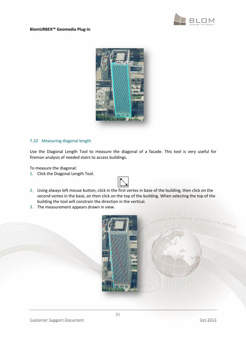
7.10 Measuring diagonal length
Use the Diagonal Length Tool to measure the diagonal of a facade. This tool is very useful for
fireman analysis of needed stairs to access buildings.
To measure the diagonal: 1. Click the Diagonal Length Tool.
2. Using always left mouse button, click in the first vertex in base of the building, then click on the
second vertex in the base, an then click on the top of the building. When selecting the top of the building the tool will constrain the direction in the vertical.
3. The measurement appears drawn in view.
BlomURBEX™ Geomedia Plug-in
32
Customer Support Document Oct 2013
7.11 Clearing measurements
Use the Eraser Tool to clear measurements in the map display.
To clear measurements: 1. Click the Eraser Tool.
2. The measurements are removed in all available views.
BlomURBEX™ Geomedia Plug-in
33
Customer Support Document Oct 2013
8 PRINTING IMAGES
BlomURBEX Viewer let print all the views opened to the selected printer, setup the page options and
preview the printing, along with the image properties if they were activated in the settings dialog.
Before printing, scroll or pan the image so that the portion we wish to print is visible in the display.
Also resize the views with the splitters and the size of the BlomURBEX Viewer window. The visible
portion of each image, and with the exact pixel size, will be send to printer.
8.1 Printing images
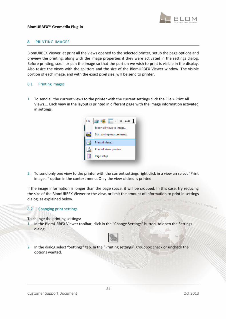
1. To send all the current views to the printer with the current settings click the File > Print All
Views…. Each view in the layout is printed in different page with the image information activated in settings.
2. To send only one view to the printer with the current settings right click in a view an select “Print
image…” option in the context menu. Only the view clicked is printed.
If the image information is longer than the page space, it will be cropped. In this case, try reducing
the size of the BlomURBEX Viewer or the view, or limit the amount of information to print in settings
dialog, as explained below.
8.2 Changing print settings
To change the printing settings: 1. In the BlomURBEX Viewer toolbar, click in the “Change Settings” button, to open the Settings
dialog.
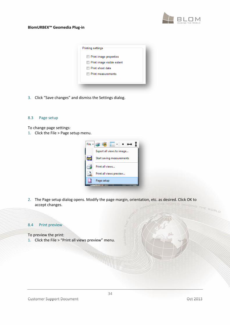
2. In the dialog select “Settings” tab. In the “Printing settings” groupbox check or uncheck the
options wanted.
BlomURBEX™ Geomedia Plug-in
34
Customer Support Document Oct 2013
3. Click “Save changes” and dismiss the Settings dialog.
8.3 Page setup
To change page settings: 1. Click the File > Page setup menu.
2. The Page setup dialog opens. Modify the page margin, orientation, etc. as desired. Click OK to
accept changes.
8.4 Print preview
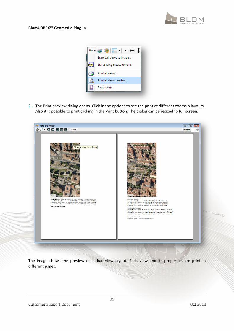
To preview the print: 1. Click the File > “Print all views preview” menu.
BlomURBEX™ Geomedia Plug-in
35
Customer Support Document Oct 2013
2. The Print preview dialog opens. Click in the options to see the print at different zooms o layouts.
Also it is possible to print clicking in the Print button. The dialog can be resized to full screen.
The image shows the preview of a dual view layout. Each view and its properties are print in
different pages.
BlomURBEX™ Geomedia Plug-in
36
Customer Support Document Oct 2013
9 EXPORTING IMAGES
9.1 Exporting all visible views
The BlomURBEX Viewer “Export all views to image” menu lets exporting the visible extent of the
active views to a set of JPG files.
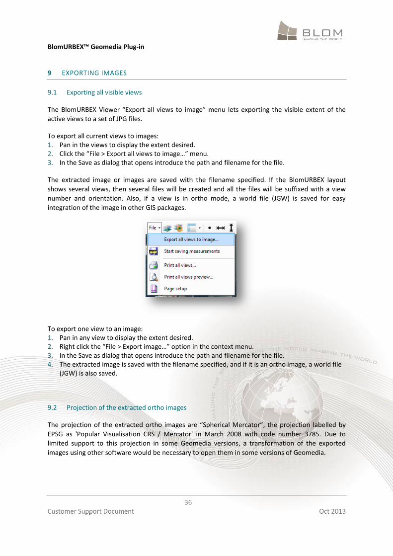
To export all current views to images: 1. Pan in the views to display the extent desired. 2. Click the “File > Export all views to image…” menu. 3. In the Save as dialog that opens introduce the path and filename for the file.
The extracted image or images are saved with the filename specified. If the BlomURBEX layout
shows several views, then several files will be created and all the files will be suffixed with a view
number and orientation. Also, if a view is in ortho mode, a world file (JGW) is saved for easy
integration of the image in other GIS packages.
To export one view to an image: 1. Pan in any view to display the extent desired. 2. Right click the “File > Export image…” option in the context menu. 3. In the Save as dialog that opens introduce the path and filename for the file. 4. The extracted image is saved with the filename specified, and if it is an ortho image, a world file
(JGW) is also saved.
9.2 Projection of the extracted ortho images
The projection of the extracted ortho images are “Spherical Mercator”, the projection labelled by
EPSG as 'Popular Visualisation CRS / Mercator' in March 2008 with code number 3785. Due to
limited support to this projection in some Geomedia versions, a transformation of the exported
images using other software would be necessary to open them in some versions of Geomedia.
BlomURBEX™ Geomedia Plug-in
37
Customer Support Document Oct 2013
10 SAVING MEASUREMENTS
BlomURBEX Viewer is able to notify when the user has made measurements in order to store this
measures into any opened table in Geomedia.
10.1 Setting measurement savings
To activate the measurement storage, it is needed to complete two one-time setup tasks. It is
needed to specify some options about the place where store the measurements, and some options
about the units and the projection to use (in the case the measurements are locations).
To specify the options regarding the place to store measurements: 5. In the BlomURBEX Viewer toolbar, click in the “Change Settings” button, to open the Settings
dialog.
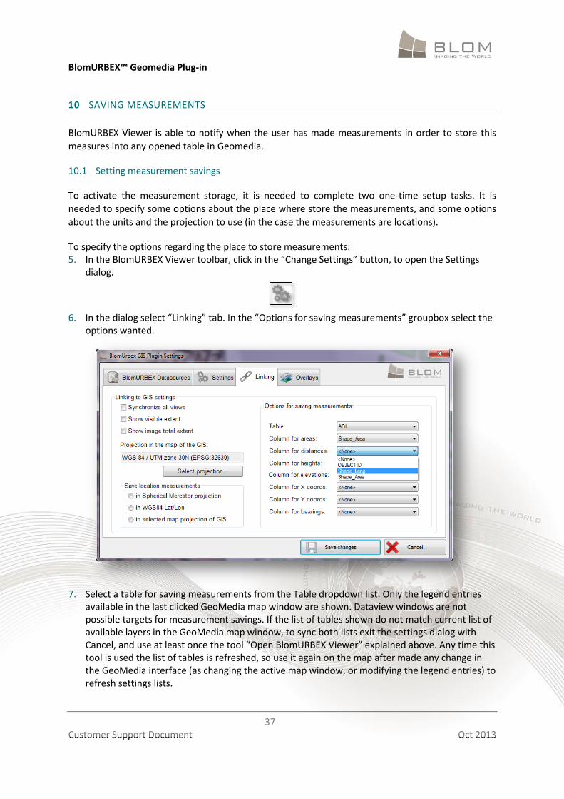
6. In the dialog select “Linking” tab. In the “Options for saving measurements” groupbox select the
options wanted.
7. Select a table for saving measurements from the Table dropdown list. Only the legend entries
available in the last clicked GeoMedia map window are shown. Dataview windows are not possible targets for measurement savings. If the list of tables shown do not match current list of available layers in the GeoMedia map window, to sync both lists exit the settings dialog with Cancel, and use at least once the tool “Open BlomURBEX Viewer” explained above. Any time this tool is used the list of tables is refreshed, so use it again on the map after made any change in the GeoMedia interface (as changing the active map window, or modifying the legend entries) to refresh settings lists.
BlomURBEX™ Geomedia Plug-in
38
Customer Support Document Oct 2013
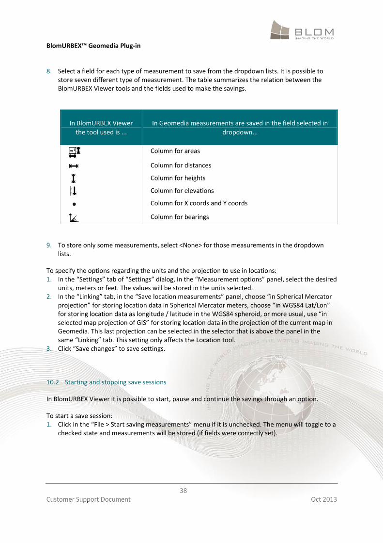
8. Select a field for each type of measurement to save from the dropdown lists. It is possible to store seven different type of measurement. The table summarizes the relation between the BlomURBEX Viewer tools and the fields used to make the savings.
In BlomURBEX Viewer
the tool used is ...
In Geomedia measurements are saved in the field selected in
dropdown...
Column for areas
Column for distances
Column for heights
Column for elevations
Column for X coords and Y coords
Column for bearings
9. To store only some measurements, select <None> for those measurements in the dropdown
lists.
To specify the options regarding the units and the projection to use in locations: 1. In the “Settings” tab of “Settings” dialog, in the “Measurement options” panel, select the desired
units, meters or feet. The values will be stored in the units selected. 2. In the “Linking” tab, in the “Save location measurements” panel, choose “in Spherical Mercator
projection” for storing location data in Spherical Mercator meters, choose “in WGS84 Lat/Lon” for storing location data as longitude / latitude in the WGS84 spheroid, or more usual, use “in selected map projection of GIS” for storing location data in the projection of the current map in Geomedia. This last projection can be selected in the selector that is above the panel in the same “Linking” tab. This setting only affects the Location tool.
3. Click “Save changes” to save settings.
10.2 Starting and stopping save sessions
In BlomURBEX Viewer it is possible to start, pause and continue the savings through an option.
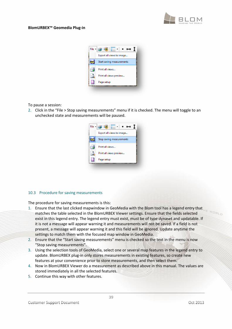
To start a save session: 1. Click in the “File > Start saving measurements” menu if it is unchecked. The menu will toggle to a
checked state and measurements will be stored (if fields were correctly set).
BlomURBEX™ Geomedia Plug-in
39
Customer Support Document Oct 2013
To pause a session: 2. Click in the “File > Stop saving measurements” menu if it is checked. The menu will toggle to an
unchecked state and measurements will be paused.
10.3 Procedure for saving measurements
The procedure for saving measurements is this: 1. Ensure that the last clicked mapwindow in GeoMedia with the Blom tool has a legend entry that
matches the table selected in the BlomURBEX Viewer settings. Ensure that the fields selected exist in this legend entry. The legend entry must exist, must be of type dynaset and updatable. If it is not a message will appear warning it and measurements will not be saved. If a field is not present, a message will appear warning it and this field will be ignored. Update anytime the settings to match them with the focused map window in GeoMedia.
2. Ensure that the “Start saving measurements” menu is checked so the text in the menu is now “Stop saving measurements”.
3. Using the selection tools of GeoMedia, select one or several map features in the legend entry to update. BlomURBEX plug-in only stores measurements in existing features, so create new features at your convenience prior to store measurements, and then select them.
4. Now in BlomURBEX Viewer do a measurement as described above in this manual. The values are stored immediately in all the selected features.
5. Continue this way with other features.
BlomURBEX™ Geomedia Plug-in
40
Customer Support Document Oct 2013
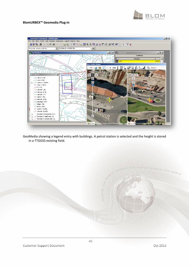
GeoMedia showing a legend entry with buildings. A petrol station is selected and the height is stored
in a TTGGSS existing field.
BlomURBEX™ Geomedia Plug-in
41
Customer Support Document Oct 2013
11 OVERLAYING TILE RASTER DATA
BlomURBEX Viewer is able to overlay tile raster data from BlomURBEX server, both in “Ortho” and
“Oblique” modes. In next chapter is explained how is possible to overlap also local vector data
loaded in Geomedia. Both tile raster layers and local vector layers can be overlapped at the same
time over the BlomURBEX Viewer. They all are treated as layers and drawn on top of the basemap
imagery.
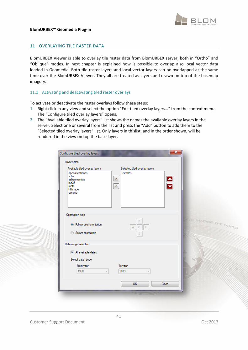
11.1 Activating and deactivating tiled raster overlays
To activate or deactivate the raster overlays follow these steps: 1. Right click in any view and select the option “Edit tiled overlay layers…” from the context menu.
The “Configure tiled overlay layers” opens. 2. The “Available tiled overlay layers” list shows the names the available overlay layers in the
server. Select one or several from the list and press the “Add” button to add them to the “Selected tiled overlay layers” list. Only layers in thislist, and in the order shown, will be rendered in the view on top the base layer.
BlomURBEX™ Geomedia Plug-in
42
Customer Support Document Oct 2013
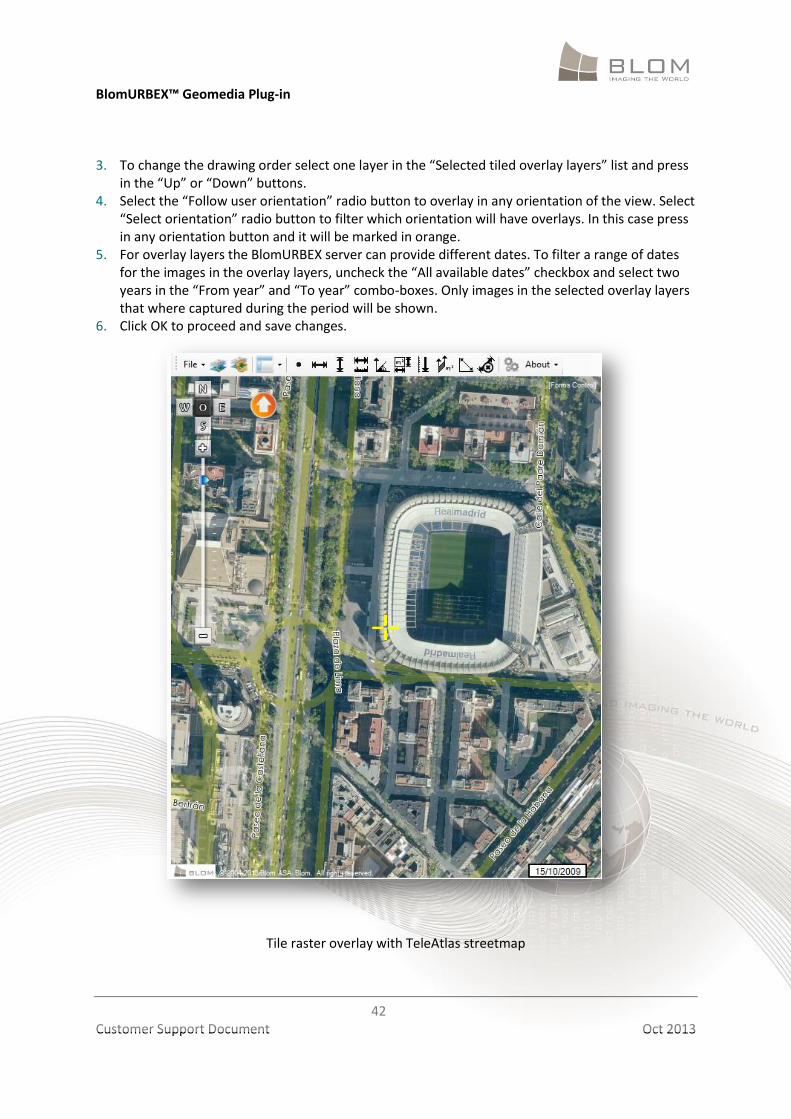
3. To change the drawing order select one layer in the “Selected tiled overlay layers” list and press
in the “Up” or “Down” buttons. 4. Select the “Follow user orientation” radio button to overlay in any orientation of the view. Select
“Select orientation” radio button to filter which orientation will have overlays. In this case press in any orientation button and it will be marked in orange.
5. For overlay layers the BlomURBEX server can provide different dates. To filter a range of dates for the images in the overlay layers, uncheck the “All available dates” checkbox and select two years in the “From year” and “To year” combo-boxes. Only images in the selected overlay layers that where captured during the period will be shown.
6. Click OK to proceed and save changes.
Tile raster overlay with TeleAtlas streetmap
BlomURBEX™ Geomedia Plug-in
43
Customer Support Document Oct 2013
12 OVERLAYING VECTOR DATA
BlomURBEX Viewer is able to overlay vector data from Geomedia on top of BlomURBEX imagery,
both in “Ortho” and “Oblique” modes.
12.1 Activating and deactivating vector overlays
To activate or deactivate the vector overlays click in “Overlay vector layers” button in the
BlomURBEX toolbar . This setting is not saved for better performance initialization. BlomURBEX
Viewer always start with the setting uncheck. It is needed to set it explicitly in each BlomURBEX
Viewer session.
Overlying on top of oblique imagery may be a long time operation. Be patient when overlaying a big number of features over oblique images. Read below for tricks to improve performance.
12.2 Refreshing vector overlays
When Overlay option is activated all the existing layers in the Geomedia active map window are
added to BlomURBEX views. If a new layer is added or any feature is modified in its geometry after
activating the Overlay option, these changes are not shown immediately. To reflect these changes is
needed to click in the “Reload overlays” button in the BlomURBEX Viewer toolbar . This
function again adds the layers to BlomURBEX; cleans all the overlays and redraw again the vector
data.
When overlaying vector data in oblique imagery, remember that vertexes of the geometries should match with the imagery at the ground level, not at the roof level. That is the reason of the apparent offset seen when overlapping over oblique imagery.
12.3 Overlay and performance considerations
To overlap geometries faster, a combination of requests to BlomURBEX server and local
interpolations is done. It is possible to adjust the precision of the interpolations.
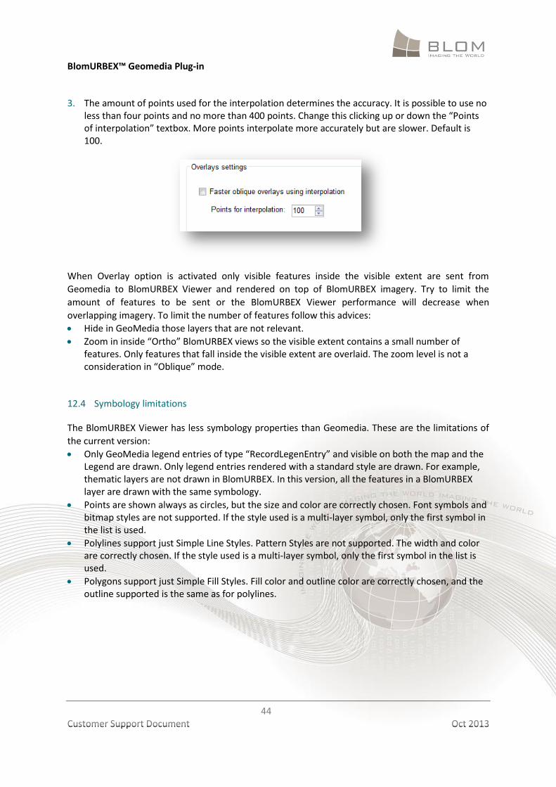
For that, follow these steps. 1. Open Settings dialog. 2. Select the Overlays tab.
BlomURBEX™ Geomedia Plug-in
44
Customer Support Document Oct 2013
3. The amount of points used for the interpolation determines the accuracy. It is possible to use no less than four points and no more than 400 points. Change this clicking up or down the “Points of interpolation” textbox. More points interpolate more accurately but are slower. Default is 100.
When Overlay option is activated only visible features inside the visible extent are sent from
Geomedia to BlomURBEX Viewer and rendered on top of BlomURBEX imagery. Try to limit the
amount of features to be sent or the BlomURBEX Viewer performance will decrease when
overlapping imagery. To limit the number of features follow this advices:
Hide in GeoMedia those layers that are not relevant.
Zoom in inside “Ortho” BlomURBEX views so the visible extent contains a small number of features. Only features that fall inside the visible extent are overlaid. The zoom level is not a consideration in “Oblique” mode.
12.4 Symbology limitations
The BlomURBEX Viewer has less symbology properties than Geomedia. These are the limitations of
the current version:
Only GeoMedia legend entries of type “RecordLegenEntry” and visible on both the map and the Legend are drawn. Only legend entries rendered with a standard style are drawn. For example, thematic layers are not drawn in BlomURBEX. In this version, all the features in a BlomURBEX layer are drawn with the same symbology.
Points are shown always as circles, but the size and color are correctly chosen. Font symbols and bitmap styles are not supported. If the style used is a multi-layer symbol, only the first symbol in the list is used.
Polylines support just Simple Line Styles. Pattern Styles are not supported. The width and color are correctly chosen. If the style used is a multi-layer symbol, only the first symbol in the list is used.
Polygons support just Simple Fill Styles. Fill color and outline color are correctly chosen, and the outline supported is the same as for polylines.
BlomURBEX™ Geomedia Plug-in
45
Customer Support Document Oct 2013
13 UNINSTALLING BLOMURBEX PLUG-IN FOR GEOMEDIA
Select Blom > Plugins > [ProductName] > “Uninstall” from the Start Menu entry that was created in
the installation process.
14 TROUBLESHOOTING
14.1 Log files
If the applications do not work as expected, the best way to know what is happening is to activate
the logging utility. Troubleshooting any issues is easier if log files are created and supplied to the
Blom technical support team.
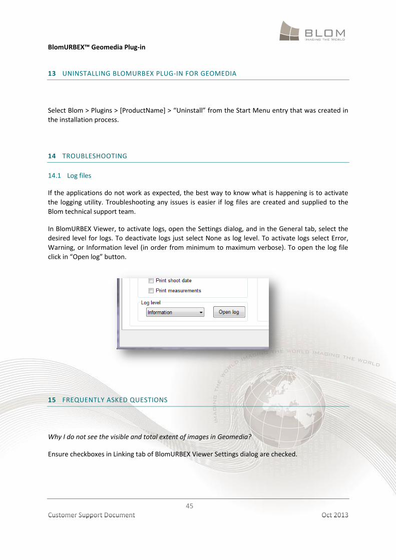
In BlomURBEX Viewer, to activate logs, open the Settings dialog, and in the General tab, select the
desired level for logs. To deactivate logs just select None as log level. To activate logs select Error,
Warning, or Information level (in order from minimum to maximum verbose). To open the log file
click in “Open log” button.
15 FREQUENTLY ASKED QUESTIONS
Why I do not see the visible and total extent of images in Geomedia?
Ensure checkboxes in Linking tab of BlomURBEX Viewer Settings dialog are checked.
BlomURBEX™ Geomedia Plug-in
46
Customer Support Document Oct 2013
Why the point I select in Geomedia is not exactly the same in the image in BlomURBEX Viewer?
The data opened in Geomedia can be in any coordinate system. When digitizing this data, a
coordinate system was used, defined by some parameters that describe the Earth and how to
convert between projections. BlomURBEX Viewer uses the Proj4 library to perform transformations
between any projection and Mercator Spheric (EPSG: 3785), the default projection that use
BlomURBEX Web Services at the moment. If the parameters used by the operator that digitizes the
data opened in Geomedia and the parameters used in DotSpatial are not the exactly the same, some
shift can occur in the location. In order to minimize this shift, it is possible to modify the epsg file
that comes in the BlomURBEX install dir. The parameters must comply with the rules that expect
Proj4 (PROJ4 format). To know more about this, check the appendix below.
What means the message “Intergraph products not found” that I obtain during installation?
At least one of the supported GeoMedia products must be installed prior to install the plug-in. If no
GeoMedia product is found, the installer could not register correctly the plug-in to work with
GeoMedia. Uninstall the plug-in, install a GeoMedia product, and then try again installing the plug-
in.
What means the error message that I obtain during un-installation?
If an error message appears during un-installation, it could be due to a corruption of the install
information in your system. Try using Windows Cleaner software to force the removal of the plug-in.
Why the measurements are not saved in GeoMedia?
The requirements to save measurements in GeoMedia are the following. If any of this requirements
are not fulfilled the saving will not takes place.
In the BlomURBEX Viewer settings dialog a table and a field must be selected for the desired measurement type. To store heights, the correct dropdown box with the field for heights must be selected, for example. If the dropdown has <None> selected that measurement will be ignored.
The “File > Start saving measurements” menu must be checked.
To be able to modify the Saving settings it is needed to click first on the map having the “Open BlomURBEX Viewer” button checked. This tries to open an BlomURBEX image but also refreshes the settings lists. Click again on the map after made any change in the GeoMedia interface (as changing the active map window, or modifying the legend entries) to refresh settings lists.
The window with the focus or active window in GeoMedia (BlomURBEX Viewer window is not in this list) must be a map window.
The focused map window must have a legend entry with the same name that was selected in the BlomURBEX Viewer settings dialog for the table.
The previous legend entry must be of type dynaset and updatable. Some sources of data for GeoMedia are not updatable. Check the GeoMedia Help about the updatable source types. Updatable means the same that “read write allowed”.
The field selected in BlomURBEX Viewer settings dialog to store the desired measurement must exist in the previous legend entry.
BlomURBEX™ Geomedia Plug-in
47
Customer Support Document Oct 2013
The previous field must be one of these types: Integer, Long, Single, Double, Currency, Text. If the field type is not Double the measurement will be converted to the field type (down casting the measurement value and perhaps losing some data), so the recommended type is Double.
In the map window some features in the previous legend entry must be selected. Measurements are saved in all the selected features.
16 APPENDIX A: HOW TO ADD NEW PROJECTIONS
The projection support relies on the PROJ4 public domain library. In the installation folder of the
plug-in a file “epsg” is provided that contains EPSG codes, names and parameters for the EPSG
coded projections. If you need to modify an existing projection, or to add support for new
projections, modify this file with any text editor following the PROJ4 rules for parameters. See the
http://proj.maptools.org/ webpage for more information.
For example, if support for the Microsoft Live Maps projection is needed, add the next two lines to
the file (the second line looks longer but is only one):
# World Mercator
<54004> +proj=merc +lat_ts=0 +lon_0=0 +k=1.000000 +x_0=0 +y_0=0 +ellps=WGS84
+datum=WGS84 +units=m no_defs <>
Or support for Google Maps projection:
<900913> +proj=merc +a=6378137 +b=6378137 +lat_ts=0.0 +lon_0=0.0 +x_0=0.0 +y_0=0 +k=1.0
+units=m +nadgrids=@null +wktext +no_defs <>
For optimize the Select projection dialog, delete from the “epsg” file any projection not needed.
Remember that each projection in the file uses two lines, so do not break the format of this file or
the plug-in could not work correctly.
Once the “epsg” file is modified, open again the Settings dialog in the plug-in and reselect again the
projection to refresh internal settings.
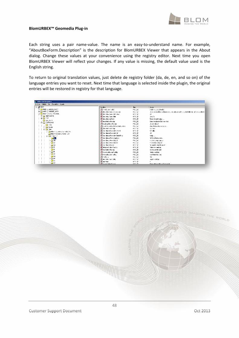
17 APPENDIX B: HOW TO IMPROVE INTERFACE TRANSLATION
The plug-in interface supports twelve languages. The strings for each language are stored in the
registry, in the path HKEY_CURRENT_USER / SOFTWARE / Blom / Urbex 2.0. Each language has a
section: english (en), español (es), deutsch (de), français (fr), italiano (it), nederlands (nl), portugués
(pt), dansk (da), norsk (no), svenska (sv), suomi (fi), româna (ro).
BlomURBEX™ Geomedia Plug-in
48
Customer Support Document Oct 2013
Each string uses a pair name-value. The name is an easy-to-understand name. For example,
“AboutBoxForm.Description” is the description for BlomURBEX Viewer that appears in the About
dialog. Change these values at your convenience using the registry editor. Next time you open
BlomURBEX Viewer will reflect your changes. If any value is missing, the default value used is the
English string.
To return to original translation values, just delete de registry folder (da, de, en, and so on) of the
language entries you want to reset. Next time that language is selected inside the plugin, the original
entries will be restored in registry for that language.