Geology and Geological Structure of Tsuruga Power Station ... › news › press › 2013 › pdf...
23
Geology and Geological Structure of Tsuruga Power Station Site D-1shatter zone(summary) Aug.01, 2013 The Japan Atomic Power Company ・Geography, geology and geological structure of the site ・Evaluation of the D-1 shatter zone - The additional survey plan - JAPC’s opinion at the Expert Meeting (Apr. 24, 2013) - NRA (Expert Meeting) ’s view at the NRA meeting (May 22, 2013) - JAPC’s opinion in the report submitted Jul.11, 2013 1
Transcript of Geology and Geological Structure of Tsuruga Power Station ... › news › press › 2013 › pdf...

Geology and Geological Structure of Tsuruga Power Station Site
D-1shatter zone(summary)
Aug.01, 2013
The Japan Atomic Power Company
・Geography, geology and geological structure of the site
・Evaluation of the D-1 shatter zone- The additional survey plan
- JAPC’s opinion at the Expert Meeting (Apr. 24, 2013)
- NRA (Expert Meeting) ’s view at the NRA meeting (May 22, 2013)
- JAPC’s opinion in the report submitted Jul.11, 2013
1

Location of Tsuruga power station
Minami-Echizen Town
Minami-Echizen Town
Takashima City
Nagahama City
●Tsuruga power station
Nagahama City
Tsuruga City
Mihama Town
TsurugaBay
WakasaBay
WakasaBay
Fukui Pref.
Gifu Pref.
Shiga Pref.Kyoto Pref.
Ishikawa Pref.
Shiga Pref.
2

-27 kmMikata
-23 kmTsuruga
14 km
21 km
12 km
18 km
15 km
23 km
18 km25 km
31 km
19 km
42 km
Length
49 km
-
-
-
-
-
-
60 km
As moving at a time
B
Continental shelf edge
Kaburagi
Faults
Nosaka
C
Shiraki-Nyu
Northern side of Utsurogi pass-
IkenokochiUrasoko-UchiikemiUrasoko-Ikenokochi
Yanagase
Mera-Kareizaki-oki
Note: Major faults within about 30km diameter are shown.
-
Lake Biwa
Wakasa Bay
B fault
Mer
a-Ka
reiza
kifa
ultYanagas e fau lt
Mikata
fault Tsur
uga
faul
t
Cfault
Northern side of Utsurogi pass-Ikenokochi fault
Goum
urafault
Yamada fault
Han
aore
faul
t
Urasoko-Uchiikemi fault
Kumagawa fault
-
FO-B faultFO-A
fault
FO-C fa
u lt
Kanbayashigawa fault
Nosaka fault
Cont in
ental
shelf
edge
fault
Kaburagi faultShiraki-Nyu fault
MIhamaPS
Kajiya fault
Daigo fault Sekigahara faultOshimizu fault
Monzen fault
0 20km
TsurugaPS
30km from Tsuruga PS
Syufukuji fault
Faults deemed to move simultaneously
Kaburagi-okifault
Major faults around Wakasa Bay
Major faults around Tsuruga power station
3

Location map of survey on the site (Units 1 and 2 side)
Unit2
Unit1
Legend
: Lineament
: Trench
(vertical) (dip)
: Preexisting drilling point around Units 1 and 2
: Drilling point for seismic back-check of Units 1 and 2
: Hole for borehole television
: Test tunnel, trial tunnel
: Electrical exploration line
: Reflection seismic survey line
: Range of precise topographical survey
Test tunnel
Trench at place B
Discharge channel drillingDrilling place A
Outcrop near lineament
Drilling point B
Seabed drilling
Range of precise topographical survey
Electrical exploration line
Reflection seismic surbey line
Interim report (No.2) (Mar.15, 2013) is partly retouched.
4

Unit1
Unit2
Distribution of major shatter zones based on additional survey result (Units 1 and 2 side)
B’
A’A
B
Ura
soko
faul
tLegend
Shatter zone and its numberDrilling point
*Additional survey results as of theend of June are reflected.
T.P. -15m horizontal section
(Vertical) (Dip)
Interim report (No.2) (Mar.15, 2013) is partly retouched.
5

Identified rock typesK
ojak
u gr
anite
Photo (drilling core)
・Holocrystalline-equiangular texture.・Grain size of minerals is about 5mm.・Minerals are mainly composed of K-feldspar, plagioclase, quartz and biotite.・Biotite granite is judged to be formed in the times between the late Cretaceous and
the Paleogene, since the values stand at around 66.6 Ma measured by K-Ar dating.
・Holocrystalline-porphyritic texture.・Grain size of phenocryst ranges 2-10 mm.・Grain size of groundmass is 1 mm or smaller.・Minerals are mainly composed of plagioclase, K-feldspar, quartz and biotite.・Granite porphyry is judged to be formed in the times between the late Cretaceous
and the Paleogene, since the values stand at around 66.3 Ma measured by K-Ardating.
・Holocrystalline-equiangular texture.・It contains a small amount of phenocryst and partly has porphyritic texture.・Groundmass in porphyritic texture is microcrystalline.・Minerals are mainly composed of quartz, K-feldspar, plagioclase and a very small
amount of biotite.・Aplite is judged to be formed in the times between the late Cretaceous and the
Paleogene, since the values stand at around 64.2 Ma measured by K-Ar dating.
・Intersertal texture.・Grain size is under 2 mm.・Minerals are mainly composed of plagioclase, pyroxene and a very small amount of
opaque minerals.・Dolerite is judged to be formed during the Neogene (Miocene), since the values
stand at around 21.1 Ma measured by K-Ar dating.
Excerpt fromInterim report (No.2)
6

Classification of fault rocks
In Kojaku granite found in the site, white fault gouge and cataclasite are distributed, while black fault gouge is distributed along dolerite.
Fault gouge
Fault gouge
ProtocataclasiteCataclasite
UltracataclasitePseudotachylyte
ProtomyloniteMylonite
Ultramylonite
Fault gouge
Megabreccia >256mmMesobreccia 10-256mm
Microbreccia <10mm
<10mm in normal
ProtocataclasiteCataclasite
Ultracataclasite<10mm in normal
ProtomyloniteMylonite
Ultramylonite
Cataclasite
Kojaku graniteFault gouge along dolerite
Crushing Fusion Recrystallization
Random fabric or foliated Foliated
Incohesive Cohesive
Fault breccia
Gra
in-s
ize
redu
ctio
n
Boundary values for sub-classification
Fault breccia
Name Proportion of visible fragments Grain size of fragments
Proportion of fragments Grain size of fragment
>30%
<30%
>50%10-50%<10%
Proportion of porphyroclasts Grain size of matrix mineral
Variable depending on deformation force and
lithology of protolith
>100μm20-100μm
<20μm
Source: Proposed classification of fault rocks (by Takagi & Kobayashi, 1996)
Interim report (No.2) (Mar.15, 2013) is partly retouched.
7

Sketch of Urasoko fault (southern slope of trench at place B)
E ←
→ W
Basement rock (aplite)
Facies
Mainly siltMainly sandMainly sand and gravel
Legend
Topsoil
Basement rock
Layer A: A layer composed of silty sand gravel layer containing angular and subangular aplite gravels and of sandy silt layer. A silt layer containing humic matter is sandwiched in certain places there. It consists of talus deposit where deposit structure is rarely seen.
Layer B: A layer of sand gravel and silty sand containing aplite as well as angular and subangular granite porphyry gravels. The upper portion consists of talus deposit where deposit structure is rarely seen and buried soil, while the lower portion is in a reduced color and consists of deposit where deposit structure is seen and talus deposit where deposit structure is not seen. The lowest portion consists of well sorted sand gravels.
Layer E: A sand gravel layer containing angular and subangular gravels of aplite, granite porphyry, biotite granite and a sand layer. These layers are composed of as well as alternate layers of sand gravel with clear deposit structure, sand and silt.
Layers C & D: The layers consist of a sand layer, silty sand layer as well as alternate layers of sand gravel with clear deposit structure and sand.
Stratum boundaryFaultMixed zone (a zone where granule materials constituting a shatter zone and sand gravels constituting the Quaternary system are mixed)
Kikai-Akahoya (K-Ah) tephra horizon
Aira-Tanzawa (AT) tephra horizon
○: 1,410 ± 40 Radiocarbon (14C) analysis of age (y. B. P.)
Southern slope
・ Basement rock consisting of aplite and Quaternary talus deposit that overlays the basement rock with unconformity are found. On the boundary between aplite and Quaternary talus deposit (layers B & E), a shatter zone (brown and grayish white clay of about 10cm wide) with a northeasterly dip of about 40° in the upper zone and about 70° in the lower zone is recognized.
・ Layer B (radiocarbon (14C) analysis of age: 24,480±190 y. B.P. to 3,960±50 y. B.P.) that contains Kikai-Akahoya tephra (about 7,300 years ago) and Aira-Tanzawa tephra (about 29,000-26,000 years ago) contacts with the basement rock in terms of a fault.
・ Displacement and deformation by the fault is not observed in layer A (radiocarbon (14C) analysis of age: 1,640±40 y. B.P. to 1,410±40 y. B.P.)
・ It is judged from the above that the latest active period is after the deposition of layer B and before the deposition of layer A.
・ In the boundary between the shatter zone and layer E, a mixed zone is continuously seen and the gravels inside layer E show strong preferred orientation. In the boundary between the shatter zone and layer B, a mixed zone is intermittently seen and the gravels inside layer B show poor preferred orientation.
・ Urasoko fault is a fault with an uplifting in the northeastern side between Kojaku granite (aplite) and Quaternary deposit. ・ Based on the results of trench survey etc., it is judged that the fault has been repeatedly active after the Late Pleistocene.・ It is judged that the last slip was at least no earlier than 4,000 years ago.・ Clay-like portions in the fault gouge are in various color tones and are distributed in striped.・ The fracture segment falling into the lower land side is displaced by a fault in the back.
Interim report (No.2) (Mar.15, 2013) is partly retouched.
8

Background of additional surveys on the shatter zones
○ The additional geological surveys have been carried out in order to collect additional data based on the opinions expressed by the Nuclear and Industrial Safety Agency (NISA) during the survey on the shatter zones in the site of Tsuruga PS on April 24, 2012 and the instructions issued by NISA,
○The basic principles and the specific plan for the additional surveys were explained at the hearing about earthquake and tsunami on May 14, 2012.
・Evaluation of activities of the crush zones in and after the Late Pleistocene should be based on the evaluation by the overlying strata analysis method.
・If evaluation based on the overlying strata analysis method would be difficult, evaluations should be carried out in a comprehensive manner, based on the results of various geological surveys and numerical analyses.
D-1
Unit 1
Unit 2
D-6
D-14
Unit3Unit4
f-13
f-19
D-5
Outcrop
Whole site・Reconfirmation of the existence of tectonic landform.
Airborne laser DEM, Air photo DEM, etc.
Outcrop・Evaluation by the overlying strata analysis method.
Tephra analysis at more sampling points.Dating of the overlying strata by OSL.
・Clarification of rock mass and quaternary depositboundary.
Detailed observation of geology through CT scan.
・Inquest of the activity age focused on fracture segments.Evaluation of the activity age by ESR, etc.
・Displacement sense of fracture segments.Measurement of slickenline’s direction.Observation of thin sections, etc.
Near Urasoko fault (in north)After confirming the geological strata of the last interglacial,
survey the relationship with the shatter zones.・Evaluation by overlying strata analysis method.
Tephra analysis at more sampling points.Dating of the overlying strata by OSL.(Tunnel survey, Trench survey)
・Inquest of the activity age focused on fracture segments.Evaluation of the activity age by ESR, etc.
・Displacement sense of fracture segments.Measurement of slickenline’s direction.Observation of thin sections, etc.
Near Urasoko fault (in south) Survey the relationship between the shatter zone and the
geological strata of the last interglacial distributed at about 30m to 50m deep underground.( Take account of the great depth and interference with the facilities. )・Evaluation by the overlying strata analysis method.
Tephra analysis at more sampling points.Dating of the overlying strata by OSL.(Deep test tunnel survey)
・Inquest of the activity age focused on fracture segments.Evaluation of the activity age by ESR, etc.
・Displacement sense of fracture segments.Measurement of slickenline’s direction.Observation of thin sections, etc.
Evaluation of the activity of the f-25 shatter zone by overlying strata analysis method.
③
④
⑤
⑥
⑧
⑨
⑦f-25
③’
②
9
Shatter zone
Dolerite Test tunnel
※Units 3 and 4 side :T.P.-9m slice
Legend
※Urasoko fault : T.P.-15m slice
Ura
soko
faul
t
0 300m
DEM : Digital Elevation ModelOSL : Optically Stimulated LuminescenceESR : Electron Spin Resonance

About the D-1 shatter zone and the G fault, the K fault
・In order to evaluate the activity of the D-1 shatter zone, the D-1 trench has been bored.・Expert Meeting call a fault “G fault” which the JAPC considers as the D-1 shatter zone.・Same as the above, Expert Meeting call a shear plane “K fault” which was found at an wall
of the D-1 trench and has displaced or deformed Quaternary deposit.【Issues at the Expert Meeting】① Depositional ages of the layers in D-1 trench② Activity period of the fault found in D-1 trench (K fault and G fault) ③ Relations between the fault found in D-1 trench (K fault and G fault) and D-1 shatter
zone.
Investigated at theconstruction of Unit 2
Unit 2
Offscraping survey of the southern slope of Unit 2 reactor building
D-1 trenchD1-1
B14-2D1-5D1-3
Unit 2 test tunnel (T.P.-15m)
No.14
No.②-1No.2
D-1 outcrop
Urasoko fault(T.P -15m)
D-1 shatter zone(T.P -15m)
K fault
G fault
10

・The hornblende in the lower part of layer⑤ corresponds with Mihama tephra, because their refractive indexes and main ingredients closely resemble each other.
・The age of Mihama tephra is pointed out to be earlier than that of Sanbe-Kisuki (110,000-115,000 years old) by Yasuno.T(1991).
→The tephra in the lower part of layer⑤ is about 120,000 years old.
・At least, both G fault and K fault haven’t displaced or deformed the upper part of layer③ and the lower part of layer⑤.
・The tephra in the lower part of layer⑤ is about 120,000 years old.→Both G fault and K fault are not “active faults to be taken into
account in seismic design.”
LL: Lower Limit
Ho: Hornblende
11
Geological plan of D-1 trench
Western pit
Northern pit
Southern pit
Urasoko fault
L-cut pit
Entrance pit
LL of DKP
LL of DKP
LL of Ho
LL of Ho
LL of Ho
LL of Ho
12
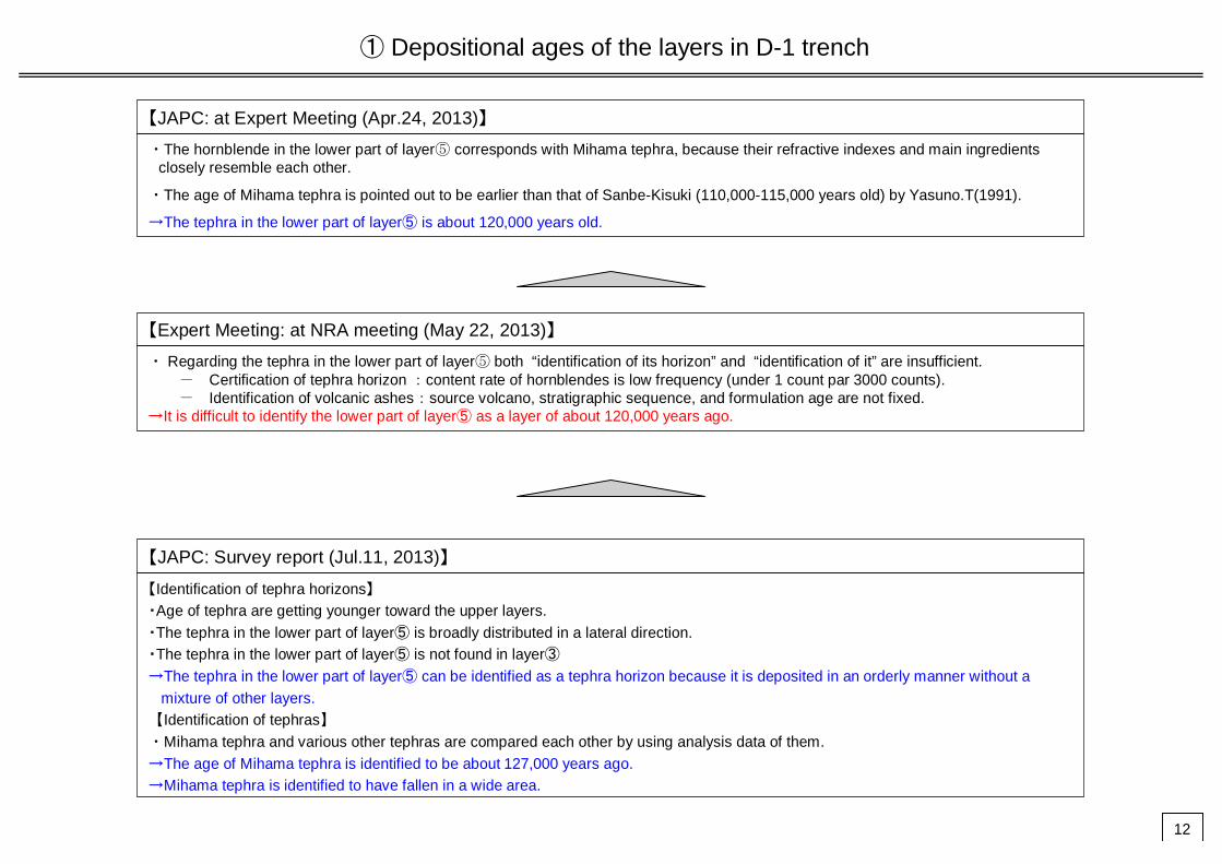
① Depositional ages of the layers in D-1 trench
【JAPC: at Expert Meeting (Apr.24, 2013)】
・The hornblende in the lower part of layer⑤ corresponds with Mihama tephra, because their refractive indexes and main ingredients closely resemble each other.
・The age of Mihama tephra is pointed out to be earlier than that of Sanbe-Kisuki (110,000-115,000 years old) by Yasuno.T(1991).
→The tephra in the lower part of layer⑤ is about 120,000 years old.
【Expert Meeting: at NRA meeting (May 22, 2013)】
・ Regarding the tephra in the lower part of layer⑤ both “identification of its horizon” and “identification of it” are insufficient. - Certification of tephra horizon :content rate of hornblendes is low frequency (under 1 count par 3000 counts).- Identification of volcanic ashes:source volcano, stratigraphic sequence, and formulation age are not fixed.
→It is difficult to identify the lower part of layer⑤ as a layer of about 120,000 years ago.
【JAPC: Survey report (Jul.11, 2013)】
【Identification of tephra horizons】・Age of tephra are getting younger toward the upper layers.・The tephra in the lower part of layer⑤ is broadly distributed in a lateral direction.・The tephra in the lower part of layer⑤ is not found in layer③→The tephra in the lower part of layer⑤ can be identified as a tephra horizon because it is deposited in an orderly manner without a
mixture of other layers. 【Identification of tephras】・Mihama tephra and various other tephras are compared each other by using analysis data of them.→The age of Mihama tephra is identified to be about 127,000 years ago.→Mihama tephra is identified to have fallen in a wide area.

Locations map of survey at D-1 shatter zone (Near D-1 trench)
G fault(Surface)
K fault(Surface)
Urasoko fault(Surface)
Mea
suri n
g li n
e
A Up pe
r
Mea
sur in
g lin
e B
Me asur
in g lin
e C
M ea s ur i ng
lin e D Lo we r
Me as u ri ng li n
e
DU pp er
Me as ur in g
lin e F
M ea sur i n g
lin e G
M ea s ur i ng
lin e G ’
Measuring
line H
Mea
suri n
g
line
A Lo wer
26-01
26-02
26-0318-01
P11
P2
P7P3
P1
P4
P5
P6
P8
P9
P10
P16
P15
P12
P14
P13
07-0307-02
Survey legend
Basement rock
Geologic legend
Name of layer
Layer post-⑦
Layer⑦
Layer⑨
Layer⑧
Layer⑥
Layer③
Layer②
Layer①
Upper part
Lower part
Layer⑤
Sampling point for pollen analysis
Measuring line for tephra analysis
※ Oxidized zone at thetop of layer③Layer④※
Measurin
g line C
’
M e as u ring li ne E ’
M e as u ring li ne E
Me a suri n
g li ne
K
M eas ur i ng li n
e L
Measuring line I
Measuring line J
Measuring
line J’
Data obtained afterApr.24, 2013 is reflected.
Sampling point for C14 dating
13

W ← → E
・Tephras are found in the order of DKP, K-Tz and the tephra in the lower part of layer⑤ (Mh) from the upper side, and no inversion is observed in the lower occurrence limits of each tephra. ・The lower occurrence limit of the tephra in the lower part of layer⑤ (Mh) is confirmed to be broadly distributed in a horizontal direction, and the peaks, which correspond to horizons, are found like K-Tz etc, at the multiple measuring lines. ・ A small amount of hornblende is found in layer③.
観察面
β quartz (/3,000
particles)
Content of heavy mineral (/3,000 particles)
Content of volcanic glass
by form (/3,000 particles)
Legend
Measuring line D Lower Measuring line E Measuring line F Measuring line G
Measuring line E’
Measuring line G’
Measuring line H
Layer⑦
Layer⑥
Layer⑤Upper part
Layer⑤Lower part
Layer②Layer①
Layer③
(β quartz 42.3 particles)
(β quartz 16.1 particles)
(GHo 6.6 particles)
(Volcanic glass Bw 1.1 particles)
Surface of observation
DKP horizon above 1.2m
Data obtained afterApr.24, 2013 is reflected.Tephra analysis at D-1 trench (projection on the slope surface 2/4)
14
DKP: about 59ka-58kaK-Tz: about 95kaMihama (Mh): about 127ka

Yasuno(1991)が示す気山露頭
H25.4.24以降得られたデータ
NEXCO drilling
NEXCO drilling
・This figure indicates the location of sampling points of tephra of which JAPC implemented main ingredient analysis of hornblende, etc.・Mihama tephra is detected at Kiyama outcrop that Yasuno(1991) pointed out, then NEXCO80(Lower) at NEXCO drilling, and BT37 at
off-Takashima of Lake Biwa, respectively. Offshore drilling in Tsuruga Bay was implemented by JAPC.
Offshore drilling in Tsuruga Bay
NEXCO drilling
Tsuruga Power Station
Drilling at off-Takashima of Lake Biwa
Kiyama outcrop that Yasuno(1991) pointed out
Kiyama outcrop that Yasuno(1991) pointed out
Tsuruga Power Station
Offshore drilling in Tsuruga Bay
Survey on regional distribution of tephra (location of existing surveys) Data obtained afterApr.24, 2013
15
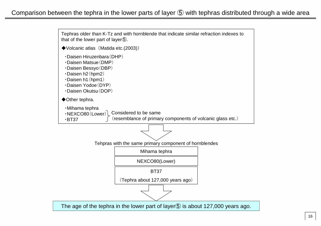
Comparison between the tephra in the lower parts of layer ⑤ with tephras distributed through a wide area
Tephras older than K-Tz and with hornblende that indicate similar refraction indexes to that of the lower part of layer⑤.
◆Volcanic atlas(Matida etc.(2003))
・Daisen Hiruzenbara(DHP)・Daisen Matsue(DMP)・Daisen Bessyo(DBP)・Daisen h2(hpm2)・Daisen h1(hpm1)・Daisen Yodoe(DYP)・Daisen Okutsu(DOP)
◆Other tephra.
・Mihama tephra・NEXCO80(Lower)・BT37
Considered to be same (resemblance of primary components of volcanic glass etc.)
Mihama tephra
NEXCO80(Lower)
BT37
(Tephra about 127,000 years ago)
Tehpras with the same primary component of hornblendes
The age of the tephra in the lower part of layer⑤ is about 127,000 years ago.
16

② Activity period of the fault found in D-1 trench (K fault and G fault)
・At least, both G fault and K fault haven’t displaced or deformed the upper part of layer③ and the lower part of layer⑤.・The tephra in the lower part of layer⑤ is about 120,000 years old.→Both G fault and K fault are not “active faults to be taken into account in seismic design.”
・Evaluation of the sedimentation period of layer⑤ is insufficient.・It could be considered that the sedimentation period of layer③ is not much earlier than that of layer⑤ and layer③ a
relatively new layer because of the appearance of weathered gravels in it.→K fault is an “active fault to be taken into account in the seismic design” because the possibility of it to have been
active after the Late Pleistocene cannot be denied.
・The age of Mihama tephra, which corresponds to the tephra in the lower part of layer⑤, is about 127,000 years old. ・The sedimentation period of layer③ is the Middle Pleistocene from the result of offshore drilling in Tsuruga Bay.・It is also confirmed that K fault has not displaced or deformed the upper part of layer③ in Genden road pit, though the
activity of K fault has been evaluated in only one survey point (the northern wall of D-1 trench).・K fault has some characteristics: running along a serpentine course in the basement rock near D-1 trench, and
decreasing its displacement sharply and disappearing in a quite narrow area.→It is elucidated that K fault is not an “active fault to be taken into account in the seismic design.
【JAPC: at Expert Meeting (Apr.24, 2013) 】
【Expert Meeting: at NRA meeting (May 22, 2013)】
【JAPC: Survey Report (Jul.11, 2013) 】
17

Location map of drilling in D-1 trench Data obtained afterApr.24, 2013 is reflected.
Urasoko fault (T.P.10m)
G fault (T.P.10m)K fault (T.P.10m)
Section BSection C
Section A
Section D
Section E
Section H
Section F
Section G
Legend of survey
Drilling
Legend of geology
Geological strata
Younger fan deposits
Layer post-⑦
Basement rock
Layer ①
Layer ②
Layer ③
Layer⑤ Lower
Upper
Layer ⑥
Layer ⑦
Layer ⑧
Layer ⑨
④(oxidized zone in the upper part of layer③)
H-1 7 70H-2 10 70H-3 11 90H-4 8 90H-5 8 90
H-5-1 10 45H-6 17 45
H-6-1 15 45H-7 11 90
H-7-1 5 90H-8 17 45
H-8-1 12 45H-9 8 90
H-9-1 12 60H-10 7 90
H-10-1 17 70H-11 11 90H-12 12 90
H-12-1 20 60H-13 20 60H-14 12 90H-15 16 90H-16 15 65H-17 16 90H-18 40 45H-19 13 90H-21 28 45H-22 13 90H-23 15 90H-24 23 50D1-1 100 45
孔名掘進長
(m)角度(°)
Drilling Location
Drilling length (m) Angle (°)
Section I
18

The apparent vertical displacement around K fault is over 1.2m to 1.8m, approximately same from northern N-S zone to NW-SE zone.In contrast, at southern NS zone from slope of removed retaining wall, displacement decreases sharply, and is about 0.05 m at west-facing slope of Genden road (G).
Displacement of K fault
Distance from Urasoko fault (m)
Appa
rent
ver
tical
dis
plac
emen
t(m
)
Urasoko faultNS zoneNW zoneNS zone
Legend for Displacement standard
Layer③ inside
Layer② upper side
Layer① upper side
Over
Variation of apparent vertical displacement against distance from Urasoko fault
Urasoko fault
Legend
K fault
Estimated location of Urasoko fault at T.P. +20m
Distance from Urasoko fault (m)
Gen
den
road
Data obtained afterApr.24, 2013
・The apparent vertical displacement of K fault in the Quaternary deposit decreases sharply in quite narrow area, and is almostdisappears in the west-facing slope of Genden road pit.
・K fault has not displaced or deformed the upper part of layer③.
Location Displacement standard
Apparent vertical displacement Remarks
Northern part of K fault
Northern wall of 1-1 pit
Southern wall of 1-1 pit
Backside slope of retaining wall
Slope of removed retaining wall
East-facing slope of Genden street
West-facing slope of Genden street
In layer③
Upper surface of layer②
In layer③
Upper surface of layer②
Upper surface of layer②
In layer③
1.3m
Over 1.2m
1.2mOver 1.1m1.5m
Over 1.3m
Over 0.6m
0.15m
0.05m
Estimated over 1.2m including flexure
Including flexure
Including flexure
Sum of the displacements of three branched faults, including flexure
Sum of the displacements of three branched faults is 0.6 m. Over 0.6m if Including flexure,
Sum of the displacements of two branched faults, flexure is not recognized.
Flexure is not recognized.
Layer①Uppersurface of layer②In layer③
19

H19-No.2N2W, 72W
Continuity between D-1 shatter zone, G fault and K fault
G faultD-1 trench
N6E, 67W2
G faultH24-No.B6-5
N7E, 89WG faultH24-No.B6-1
N3E, 81W
H24-No.B14-2N1W, 76W
Urasoko faultT.P.-70m
D-1 shatter zoneT.P.-70m
H19-No.14N20E, 81W
H20-No.②-1
D-1 outcropN9E, 73W
Test tunnel B(TP.-15m)N11W,78W
Test tunnel A(TP.-15m)N1E,88W
Test tunnel C(TP.-15m)N28E,84W
Basement rock of theshear test tunnel(TP.-15m) N3E,81W
Confirmed normal sense of displacement
Offscraping survey of the backslope of Unit2 reactor building
2-1 pit
Western pit
1-1 pit
Northern pit
Southern pit
Entrance pit
K fa
ultG fa
ult
Uras ok o fau lt
L-cut pit
20

③ Relations between the fault found in D-1 trench (K fault and G fault) and D-1 shatter zone
・’The strike and the dip’ and ‘the displacement senses of the last slips’ of the D-1 shatter zone is similar to the G fault but not to the K fault.
→ The D-1 shatter zone continues to the G fault but not to the K fault.
・The strike of the K fault changes from N-S to NNW-SSE in the D-1 trench.・At drilling hole B14-2, the fracture segments had the reverse fault senses which is the feature of the K fault
has not been recognized.→ At least, the K fault does not extend southward (i,.e., toward Unit2 reactor building) beyond B14-2 drilling hole.
・It is likely that the JAPC has not appropriately identified the displacement sense of the last slip.→It cannot be determined that the G fault and the D-1 shatter zone are identical.
・Both the G fault and the K fault are located near the extension of the D-1 shatter zone, and their shapes (strike and dips) are very similar to that of D-1 shatter zone.
→It is highly likely that G fault and K fault have continuous structure with D-1 shatter zone.
・Totally considering the continuity between D-1 shatter zone, G fault and K fault with additional viewpoints. (Viewpoints so far)
“Strike and dip” and “Displacement sense of the last slip”(Additional viewpoints)
“Structure of fault gouge”, “Color tone of fault gouge”, “Component minerals of fault gouge”, etc.→ It became much clear that the D-1 shatter zone continues to the G fault but not to the K fault.
【JAPC: at Expert Meeting (Apr.24, 2013) 】
【Expert Meeting: at NRA meeting (May 22, 2013)】
【JAPC: Survey Report (Jul.11, 2013) 】
21

Characteristics of the shatter zones Data obtained afterApr.24, 2013 is reflected.
CharacteristicD-1 shatter zone
(Back slope of Unit2 reactor building, D1-2 to D1-5 hole)G fault
(Northern pit of D-1 trench, etc.)K fault
(1-1 pit of D-1 trench, etc.)
Displacement sense Normal fault Normal fault Reverse fault
Microstructure of fault gouge
・Consti tuent particlesare grinded into round.
・Surface structure is developed and comparatively clear.
・Constituent particles are grinded into round.
・Surface structure is developed and comparatively clear.
・Constituent particlesare angular gravel.
・Surface structures are not clear.
Structure of fault gouge Striped Striped No specific
structure
Color tones of fault gouge Yellow, brown, etc. yellowish orange,
brownGrayish red, grayish white, etc.
Width of fault Narrow Narrow Wide
Solidness of fault gouge Tight T ight Soft
Strike Mainly N-S N-SWidely snake in basement rock(between N-S and NE-SW)
X-ray diffractionanalysis
Contain- smectite(sm)- kaolinite(kln)- quartz(qtz)
Contain - smectite(sm)- kaolinite(kln)- quartz(qtz)
Contain -high volume of smect ite(sm)- kaolinite(kln)
Not contain - quartz(qtz)
Evaluation of continuity G fault continues to D-1 shatter zone. K fault does not continue to D-1 shatter zone.
Evaluation of activ ity
G fault has not displaced or deformed layer①.G fault is not “a fault that has a possibility to be active in the future”.
K fault has not displaced or deformed the lower part of layer⑤.K fault is not “a fault that has a possibili ty to be active in the future”.
E‘-1 holeE‘-1 hole
A-11 holeA-11 hole
D1-4 holeD1-4 holeE’-1 holeE’-1 hole
2-1 pit2-1 pit
Southern slopeSouthern slope A-11 holeA-11 hole
Southern s lopeSouthern s lope North pitNorth pit
sm
sm smkln
sm
sm smklnsm
sm,klnill ill,qtz
klnqtzsm
sm,klnill ill,qtz
klnqtzsmsm,kln
qtz qtzklnsmsm,kln
qtz qtzkln
22

Overall judgment of the survey report (Jul.11, 2013)
It is elucidated that both D-1 shatter zone (including G fault) and K fault are not “active faults to be taken into account in the seismic design.
① Depositional ages of the layers in D-1 trench The tephra in the lower part of layer⑤ is identified as a tephra horizon.
・Age of tephra are getting younger toward the upper layers.・The tephra in the lower part of layer⑤ is broadly distributed in a lateral direction.・The tephra in the lower part of layer⑤ is not found in layer③
The age of Mihama tephra is identified to be about 127,000 years ago.・Mihama tephra and various other tephras are compared each other.
② Activity period of the fault found in D-1 trench (K fault and G fault) K fault is not an “active faults to be taken into account in seismic design.”・The age of Mihama tephra in the lower part of layer⑤ is about 127,000 years old. ・The sedimentation period of layer③ is the Middle Pleistocene.・It is confirmed that K fault has not displaced or deformed at the two survey points.・K fault has some characteristics: running along a serpentine course in the basement rock near D-1 trench, and
decreasing its displacement sharply and disappearing in a quite narrow area.
③ Relations between the fault found in D-1 trench (K fault and G fault) and D-1 shatter zone It became much clear that D-1 shatter zone continues to G fault but not to K fault.
(Viewpoints so far)“Strike and dip” and “Displacement sense of the last slip”
(Additional viewpoints)“Structure of fault gouge”, “Color tone of fault gouge”, “Component minerals of fault gouge”, etc.
On the issues below shown in the view of the Expert Meeting at May 22, the evaluation is implemented based on the survey results as of the eng of June.
23