GEOLOGICAL IMPACT ASSESSMENT REPORT
25
GEOLOGICAL IMPACT ASSESSMENT REPORT SPECIALIST INPUT FOR THE ENVIRONMENTAL IMPACT ASSESSMENT FOR THE PROPOSED VARIOUS CONCENTRATING SOLAR POWER COMPONENTS (CSP) AS PART OF THE FUTURE KAROSHOEK SOLAR VALLEY PARK, NEAR UPINGTON, NORTHERN CAPE PROVINCE, SOUTH AFRICA 14 June 2012 (Rev 2) Prepared for: SAVANNAH ENVIRONMENTAL (PTY) LTD UNIT 606, EGLIN OFFICE PARK 14 EGLIN RD, SUNNINGHILL, GAUTENG PO BOX 148, SUNNINGHILL, 2157 SOUTH AFRICA TEL: +27 (0)11 2346621 www.savannahsa.com Prepared by: OUTENIQUA GEOTECHNICAL SERVICES cc 26 COVE ST, KNYSNA PO BOX 3186, GEORGE INDUSTRIA, 6536 SOUTH AFRICA TEL: +27 (0)44 3820502 www.outeniqualab.co.za Ref No: 2012\Savannah\Karoshoek\Ilanga Karoshoek Solar Geological Report 14.6.2012 Rev 2
Transcript of GEOLOGICAL IMPACT ASSESSMENT REPORT

GEOLOGICAL IMPACT ASSESSMENT REPORT
SPECIALIST INPUT FOR THE ENVIRONMENTAL IMPACT ASSESSMENT FOR THE PROPOSED VARIOUS CONCENTRATING SOLAR POWER
COMPONENTS (CSP) AS PART OF THE FUTURE KAROSHOEK SOLAR VALLEY PARK, NEAR UPINGTON, NORTHERN CAPE PROVINCE, SOUTH
AFRICA
14 June 2012 (Rev 2)
Prepared for: SAVANNAH ENVIRONMENTAL (PTY) LTD UNIT 606, EGLIN OFFICE PARK 14 EGLIN RD, SUNNINGHILL, GAUTENG PO BOX 148, SUNNINGHILL, 2157 SOUTH AFRICA TEL: +27 (0)11 2346621 www.savannahsa.com
Prepared by: OUTENIQUA GEOTECHNICAL SERVICES cc 26 COVE ST, KNYSNA PO BOX 3186, GEORGE INDUSTRIA, 6536 SOUTH AFRICA TEL: +27 (0)44 3820502 www.outeniqualab.co.za
Ref No: 2012\Savannah\Karoshoek\Ilanga Karoshoek Solar Geological Report 14.6.2012 Rev 2

1
List of abbreviations and definitions AMSL: Above mean sea level ECO: Environmental Control Officer EIA: Environmental Impact Assessment EMP: Environmental Management Plan ER: Engineer’s representative Ma: Million years ago NEMA: National Environmental Management Act 107 of 1998 NGL: Natural ground level

2
1. INTRODUCTION 1.1. Background
FG Emvelo Energy (Pty) Ltd is currently undertaking an EIA process to determine the environmental feasibility of the proposed concentrating solar power plant (CSP) and associated infrastructure on a site located approximately 30 km east of Upington, in the Northern Cape Province (see Figure 1).
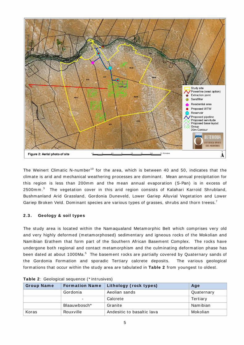
The proposed CSP project comprises a number of sub-projects or components as indicated in Table 1 and Figure 2.
Table 1: Project components Site area Project Name and Description DEA Reference
number Site 2 Karoshoek CPVPD 1 (1 x 25 MW Concentrating
photovoltaic or parabolic dish technology project) 14/12/16/3/3/2/292
Karoshoek CPVPD 2 (1 x 25 MW Concentrating photovoltaic or parabolic dish technology project)
14/12/16/3/3/2/291
Karoshoek CPVPD 3 (1 x 25 MW Concentrating photovoltaic or parabolic dish technology project)
14/12/16/3/3/2/290
Karoshoek CPVPD 4 (1 x 25 MW Concentrating photovoltaic or parabolic dish technology project)
14/12/16/3/3/2/289
Site 1.1 Karoshoek LF 1 (1 x 100 MW Linear Fresnel) 14/12/16/3/3/2/293 Site 1.3 Karoshoek PT (1 x 100 MW Parabolic Trough) 14/12/16/3/3/2/294 Site 1.4 Karoshoek LFT 2 (1 x 100 MW Linear Fresnel or Parabolic
Trough) 14/12/16/3/3/2/299
Site 3 Karoshoek Tower 1 (1 x 50MW Tower) 14/12/16/3/3/2/298 Karoshoek Tower 2 (1 x 50MW Tower) 14/12/16/3/3/2/297
Site 4 Karoshoek LFTT 1 (1 X 100 MW Linear Fresnel or Parabolic Trough or Tower)
14/12/16/3/3/2/296
Site 5 Karoshoek LFTT 2 (1 X 100 MW Linear Fresnel or Parabolic Trough or Tower)
14/12/16/3/3/2/295
Grid connection
Electricity distribution line(s) which will connect to an on-site substation / switchyard
14/12/16/3/3/2/288
Site 1.2 is the site where the already authorised Ilanga project is to be located. Although each project component is studied individually, this report broadly considers all project components as a whole and the description of the affected environment encompasses all components. Similarly, the potential impacts that are identified are relevant to all the components unless otherwise stated.
1.2. Legislation
In terms of the EIA regulations published in terms of Section 24(5) of the National Environmental Management Act (NEMA, No 107 of 1998), the applicant requires authorisation from the National

3
Department of Environmental Affairs (DEA) (in consultation with the Northern Cape Department of Agriculture and Nature Conservation) for the undertaking of the proposed project. This specialist study is undertaken in accordance with Regulation 17 of the NEMA. 1.3. Terms of reference Savannah Environmental has been appointed by FG Emvelo Energy (Pty) Ltd to carry out the EIA process for the proposed activities. Specialist input is required in order to assess the environmental impacts on the geology and soil cover associated with the proposed activity. Savannah Environmental has appointed Outeniqua Geotechnical Services to conduct a specialist geological study and impact assessment. The scope of work is as follows: Describe the geology and soil types and discuss the potential environmental impacts relating
to the geology and soil cover that may be associated with the proposed activity. Quantitatively assess the potential negative and positive impacts Provide mitigating measures for inclusion in the EMP. 1.4. Limitations Information provided in this specialist report has been based on information provided by the developer, published scientific literature, and maps. No detailed soil investigation or verification of the official geological maps was conducted. The information provided in this report is deemed adequate for the EIA process. 1.5. Authors credentials & declaration of independence The author of this report, Iain Paton of Outeniqua Geotechnical Services cc (OGS), is a professional engineering geologist registered with the South African Council for Natural and Scientific Professions (Pr Sci Nat # 400236/07) with 14 years experience in the built environment. Iain Paton is a member of the South African Institute of Engineering and Environmental Geologists (SAIEG) and the Geotechnical Division of the South African Institute of Civil Engineering (SAICE). Iain Paton declares that he does not have any financial interest in the undertaking of the activity, other than remuneration for work performed in the compilation of this specialist report. 2. SITE DESCRIPTION 2.1. Location The facility is proposed on the following farm portions:
» Karos 959/0 » Annashoek 41/3 » Matjiesrivier 41/2

4
» 1Matjiesrivier 41/Re » Zandemm 944/0
The study area is accessed via the N10 from Upington, which is the nearest major commercial centre (see Figure 1).
2.2. Topography, climate, & vegetation cover The eastern and northern portions of the study area are characterised by hilly topography, and the remaining area, which forms the majority of the study area, is characterised by relatively low relief (see Figure 2). The altitude range across the study area is 820m to 1100m amsl. Numerous natural ephemeral drainage lines traverse the study area, generally flowing in a northerly direction towards the Orange River.
1 No development is proposed on RE Portion of Matjiesrivier 41 at this stage, but the farm portion is included in the project scope as it is envisaged for future development
5
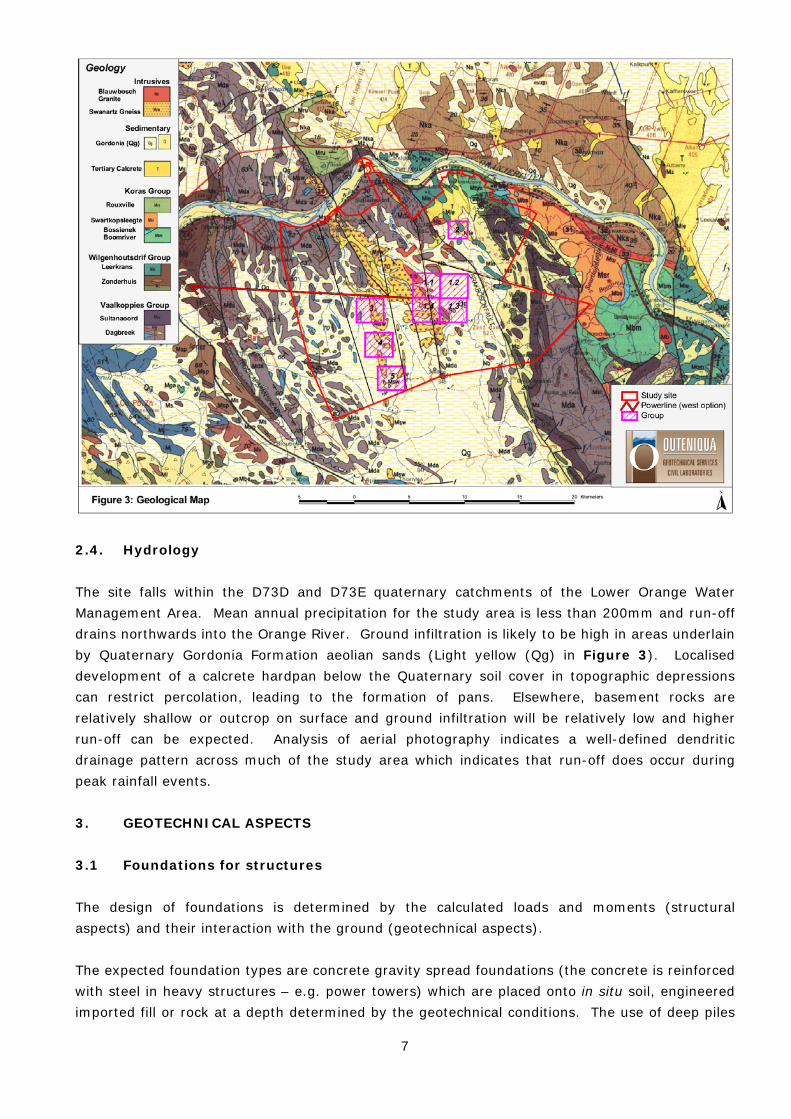
The Weinert Climatic N-number10 for the area, which is between 40 and 50, indicates that the climate is arid and mechanical weathering processes are dominant. Mean annual precipitation for this region is less than 200mm and the mean annual evaporation (S-Pan) is in excess of 2500mm.3 The vegetation cover in this arid region consists of Kalahari Karroid Shrubland, Bushmanland Arid Grassland, Gordonia Duneveld, Lower Gariep Alluvial Vegetation and Lower Gariep Broken Veld. Dominant species are various types of grasses, shrubs and thorn treess.7 2.3. Geology & soil types The study area is located within the Namaqualand Metamorphic Belt which comprises very old and very highly deformed (metamorphosed) sedimentary and igneous rocks of the Mokolian and Namibian Erathem that form part of the Southern African Basement Complex. The rocks have undergone both regional and contact metamorphism and the culminating deformation phase has been dated at about 1000Ma.5 The basement rocks are partially covered by Quaternary sands of the Gordonia Formation and sporadic Tertiary calcrete deposits. The various geological formations that occur within the study area are tabulated in Table 2 from youngest to oldest.
Table 2: Geological sequence (*intrusives) Group Name Formation Name Lithology (rock types) Age Gordonia Aeolian sands Quaternary - Calcrete Tertiary Blaauwbosch* Granite Namibian Koras Rouxville Andesitic to basaltic lava Mokolian

6
Group Name Formation Name Lithology (rock types) Age Swartkopsleegte Quartz-feldspar porphyry Mokolian Bossienek Conglomerate, sandstone, mudstone MokolianBoomrivier Andesitic to basaltic lava Mokolian
Wilgenhoutsdrif Leerkrans Metabasalt, felsic lavas, greenschist, conglomerate, chert
Mokolian
Zonderhuis Phyllite, schist, carbonate rocks, conglomerate, serpentinite, quartzite
Mokolian
Vaalkoppies Sultanaoord Quartzite, phyllite MokolianDagbreek Quartzite, schist grading into gneiss,
migmatite, amphibolite Mokolian
Swanartz* Gniess Mokolian The proposed solar facilities are underlain by both Quaternary unconsolidated sands of the Gordonia Formation and various basement rocks (dominantly gneiss, granite metavolcanics and quartzite). The proposed power-line route indicated in Figure 3 traverses the same Quaternary soil cover and basement rocks. There are several NW-SE trending geological faults traversing the study area which are indicated on the geological map in Figure 3. The dominant fault system is the Brakbosch Fault which traverses the farms Zandemm 944 and Karos 959 in the eastern part of the study area. The activity of these faults is considered dormant and the seismic activity of the area is considered low. The maximum anticipated seismic activity is rated as V on the Modified Mercalli Scale (movement felt by all, some damage to plaster, chimneys) and peak horizontal ground accelerations are typically less than 50cm/s with a 10% chance of being exceeded at least once in a 50 year period. No formal mining operations are known to have taken place within the study area. Rock outcrops are common on the higher relief areas, specifically the northern and eastern portions of the study area. The sand cover is likely to be thickest in the southern, central and western lowland areas where the bulk of the infrastructure is proposed.
7
2.4. Hydrology The site falls within the D73D and D73E quaternary catchments of the Lower Orange Water Management Area. Mean annual precipitation for the study area is less than 200mm and run-off drains northwards into the Orange River. Ground infiltration is likely to be high in areas underlain by Quaternary Gordonia Formation aeolian sands (Light yellow (Qg) in Figure 3). Localised development of a calcrete hardpan below the Quaternary soil cover in topographic depressions can restrict percolation, leading to the formation of pans. Elsewhere, basement rocks are relatively shallow or outcrop on surface and ground infiltration will be relatively low and higher run-off can be expected. Analysis of aerial photography indicates a well-defined dendritic drainage pattern across much of the study area which indicates that run-off does occur during peak rainfall events. 3. GEOTECHNICAL ASPECTS 3.1 Foundations for structures The design of foundations is determined by the calculated loads and moments (structural aspects) and their interaction with the ground (geotechnical aspects). The expected foundation types are concrete gravity spread foundations (the concrete is reinforced with steel in heavy structures – e.g. power towers) which are placed onto in situ soil, engineered imported fill or rock at a depth determined by the geotechnical conditions. The use of deep piles

8
is unlikely on this particular site but a comprehensive geotechnical investigation will have to be undertaken by the developer in order to determine the geotechnical nature of the site. 3.2. Access roads Access roads are required onto site and between structures for the construction and maintenance of infrastructure. The access roads are normally constructed with a gravel wearing course on the in situ soil (roadbed) or an imported selected subgrade layer. The design of roads is dependent on the anticipated traffic volumes and axle loads. The natural gradients of the site are always taken into account for the construction of access roads. 3.3. Underground services Excavations for buried services (pipelines) may encounter shallow rock. In some areas a tracked excavator with a rock bucket may be required to rip through weathered rock. Alternatively, hydraulic breakers may have to be used to excavate through hard rock. Blasting is used as a last resort in extremely difficult excavations. 4. IMPACT ASSESSMENT The geological impact assessment aims to assess the impact that the proposed development will have on the geological environment which broadly includes natural soil cover, bedrock and landforms. Important or prominent geological features or landforms that contribute to the aesthetic scenery or geological interest in the area also considered in the impact study. Archaeological and Palaeontological features are not assessed in this report. Impacts on the geohydrology are also not covered in this study. 4.1. Soil degradation Soil degradation is the negative alteration of the natural soil profile, usually directly or indirectly related to human activity. Soil degradation due to construction activity will negatively affect soil formation, natural weathering processes, moisture levels and soil stability. This will, in turn, affect biological processes operating in the soil. Soil degradation includes erosion (i.e. due to water and wind), soil removal, mixing, wetting, compaction, pollution, salinisation, crusting, and acidification. The proposed activity may potentially result in all or some of the above negative direct impacts. The proposed activity could also result in negative indirect impacts, such as increased siltation in waterways downstream from the site or dust pollution in the area surrounding the site. The severity or significance of the various impacts is related to the nature and extent of the activity. Impacts on soil degradation are primarily related to the construction phase with insignificant impacts in the post construction and decommissioning phases.
9
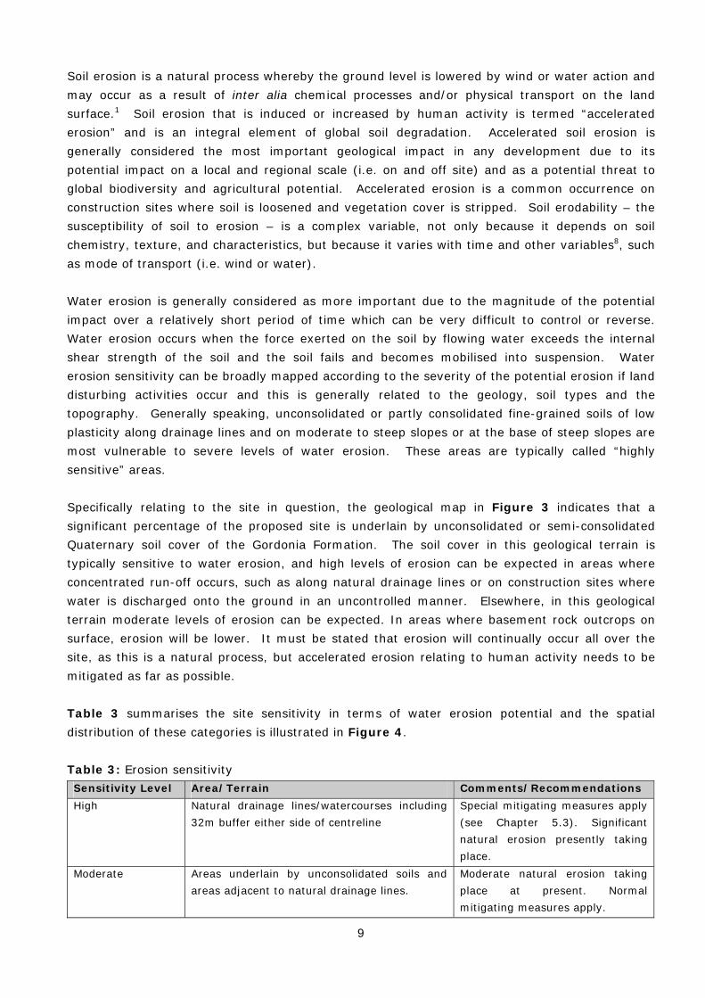
Soil erosion is a natural process whereby the ground level is lowered by wind or water action and may occur as a result of inter alia chemical processes and/or physical transport on the land surface.1 Soil erosion that is induced or increased by human activity is termed “accelerated erosion” and is an integral element of global soil degradation. Accelerated soil erosion is generally considered the most important geological impact in any development due to its potential impact on a local and regional scale (i.e. on and off site) and as a potential threat to global biodiversity and agricultural potential. Accelerated erosion is a common occurrence on construction sites where soil is loosened and vegetation cover is stripped. Soil erodability – the susceptibility of soil to erosion – is a complex variable, not only because it depends on soil chemistry, texture, and characteristics, but because it varies with time and other variables8, such as mode of transport (i.e. wind or water). Water erosion is generally considered as more important due to the magnitude of the potential impact over a relatively short period of time which can be very difficult to control or reverse. Water erosion occurs when the force exerted on the soil by flowing water exceeds the internal shear strength of the soil and the soil fails and becomes mobilised into suspension. Water erosion sensitivity can be broadly mapped according to the severity of the potential erosion if land disturbing activities occur and this is generally related to the geology, soil types and the topography. Generally speaking, unconsolidated or partly consolidated fine-grained soils of low plasticity along drainage lines and on moderate to steep slopes or at the base of steep slopes are most vulnerable to severe levels of water erosion. These areas are typically called “highly sensitive” areas. Specifically relating to the site in question, the geological map in Figure 3 indicates that a significant percentage of the proposed site is underlain by unconsolidated or semi-consolidated Quaternary soil cover of the Gordonia Formation. The soil cover in this geological terrain is typically sensitive to water erosion, and high levels of erosion can be expected in areas where concentrated run-off occurs, such as along natural drainage lines or on construction sites where water is discharged onto the ground in an uncontrolled manner. Elsewhere, in this geological terrain moderate levels of erosion can be expected. In areas where basement rock outcrops on surface, erosion will be lower. It must be stated that erosion will continually occur all over the site, as this is a natural process, but accelerated erosion relating to human activity needs to be mitigated as far as possible. Table 3 summarises the site sensitivity in terms of water erosion potential and the spatial distribution of these categories is illustrated in Figure 4. Table 3: Erosion sensitivity Sensitivity Level Area/Terrain Comments/Recommendations High Natural drainage lines/watercourses including
32m buffer either side of centreline
Special mitigating measures apply (see Chapter 5.3). Significant natural erosion presently taking place.
Moderate Areas underlain by unconsolidated soils and areas adjacent to natural drainage lines.
Moderate natural erosion taking place at present. Normal mitigating measures apply.

10
The distribution of thick deposits of unconsolidated soils can only be accurately determined by means of a detailed geotechnical investigation. Wind erosion from areas that are stripped of vegetation should not be underestimated and can lead to severe dust pollution which will attract negative response from neighbours. 4.2. Degradation of bedrock and landforms (natural topography) Foundation excavations for the 200m high power-tower are expected to be between 5-10m deep and 40m in diameter (depending on local geotechnical conditions). The excavations will be filled with concrete and covered up, thus leaving no visible scar on the landscape and no envisaged instability. The rock removed from the excavation will probably be re-used elsewhere on the site. Foundations for smaller structures such as linear Fresnel’s and parabolic troughs will be considerably smaller and shallower with significantly less impact on bedrock. Similarly, excavations for pipelines will be typically limited to a depth of approximately 1.5m. The impact on the bedrock is considered to be minor in terms of these activities. However, the cutting of access roads through areas of high relief will involve significant excavations into bedrock and this activity could carry a moderate to high impact on bedrock, depending on the proposed road layouts. The main environmental impacts of cutting into bedrock include unsightly scars in the hillside, alteration of the hydrological regime, soil degradation and slope instability.
11
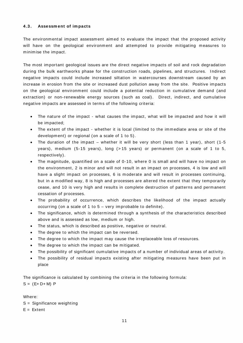
4.3. Assessment of impacts The environmental impact assessment aimed to evaluate the impact that the proposed activity will have on the geological environment and attempted to provide mitigating measures to minimise the impact. The most important geological issues are the direct negative impacts of soil and rock degradation during the bulk earthworks phase for the construction roads, pipelines, and structures. Indirect negative impacts could include increased siltation in watercourses downstream caused by an increase in erosion from the site or increased dust pollution away from the site. Positive impacts on the geological environment could include a potential reduction in cumulative demand (and extraction) or non-renewable energy sources (such as coal). Direct, indirect, and cumulative negative impacts are assessed in terms of the following criteria:
The nature of the impact - what causes the impact, what will be impacted and how it will be impacted;
The extent of the impact - whether it is local (limited to the immediate area or site of the development) or regional (on a scale of 1 to 5).
The duration of the impact – whether it will be very short (less than 1 year), short (1-5 years), medium (5-15 years), long (>15 years) or permanent (on a scale of 1 to 5, respectively).
The magnitude, quantified on a scale of 0-10, where 0 is small and will have no impact on the environment, 2 is minor and will not result in an impact on processes, 4 is low and will have a slight impact on processes, 6 is moderate and will result in processes continuing, but in a modified way, 8 is high and processes are altered the extent that they temporarily cease, and 10 is very high and results in complete destruction of patterns and permanent cessation of processes.
The probability of occurrence, which describes the likelihood of the impact actually occurring (on a scale of 1 to 5 – very improbable to definite).
The significance, which is determined through a synthesis of the characteristics described above and is assessed as low, medium or high.
The status, which is described as positive, negative or neutral. The degree to which the impact can be reversed. The degree to which the impact may cause the irreplaceable loss of resources. The degree to which the impact can be mitigated. The possibility of significant cumulative impacts of a number of individual areas of activity. The possibility of residual impacts existing after mitigating measures have been put in
place The significance is calculated by combining the criteria in the following formula: S = (E+D+M) P Where: S = Significance weighting E = Extent

12
D = Duration M = Magnitude P = Probability The significance weightings for each potential impact are as follows: <30 points: Low (i.e. where this impact would not have a direct influence on the decision to develop in the area); 30-60 points: Moderate (i.e. where the impact could influence the decision to develop in the area unless it is effectively mitigated); >60 points: High (i.e. where the impact will influence the decision to develop in the area). 4.3.1. Direct impacts An assessment of the individual direct potential impacts associated with the proposed activity is outlined in Table 4. Table 4: Assessment of potential direct impacts Nature: Soil and rock degradation – Excavation and removal of soil and/or rock for deep foundations (power tower). Without mitigation With mitigation Extent Local (1) Local (1) Duration Long term (4) Long term (4) Magnitude Moderate (6) Low (4) Probability Definite (5) Definite (5) Significance Moderate (55) Moderate (45) Status Negative Negative Reversibility Practically irreversible Partially reversible Irreplaceable loss of resources?
Yes, but minor Yes, minor
Can impacts be mitigated?
To a certain extent.
Mitigation: » Locate heavy structures on flat ground to minimise cut and fill operations. » Re-use excavated rock for road-building. » Reinstate and rehabilitate natural ground levels and topsoil after construction and
decommission. Cumulative impacts:
» Although the impact of soil and rock removal for the proposed activity has a moderate significance, the cumulative impact of soil removal in the area is considered low due to localised nature of the impact and the undeveloped nature of the area.
Residual impacts:
» Slow regeneration of topsoil. » Complete removal of deep foundations after decommission is impractical but it is
unlikely to have any significant impact on local biodiversity in the long term
Nature: Soil and rock degradation – Excavation and removal of soil and/or rock for roads, pipelines and light foundations. Without mitigation With mitigation Extent Local (1) Local (1) Duration Long term (4) Long term (4)

13
Magnitude Moderate (6) Low (4) Probability Definite (5) Definite (5) Significance Moderate (55) Moderate (45) Status Negative Negative Reversibility Partially reversible Partially reversible Irreplaceable loss of resources?
Yes, minor Yes, minor
Can impacts be mitigated?
Yes, to a certain extent.
Mitigation: » Use existing roads where possible. » Design platforms and roads according to contours to minimise cut and fill
operations. » Restrict activity outside of authorised construction areas. » Rehabilitate soil in activity areas after construction.
Cumulative impacts:
» Although the impact of soil removal for the proposed activity has a moderate significance, the cumulative impact of soil removal in the area is considered low due to undeveloped nature of the area.
Residual impacts:
» Minor negative – slow regeneration of topsoil.
Nature: Soil degradation – Loosening, mixing, wetting & compacting of natural soil in construction areas. Without mitigation With mitigation Extent Local (1) Local (1) Duration Medium term (3) Short term (2) Magnitude Moderate (6) Low (4) Probability Definite (5) Definite (5) Significance Moderate (50) Moderate (35) Status Negative Negative Reversibility Irreversible Partially reversible Irreplaceable loss of resources?
Yes Yes, minor
Can impacts be mitigated?
Yes, to a certain extent
Mitigation: » Use existing roads where possible. » Design platforms and roads according to contours to minimise cut and fill
operations. » Control activity outside of construction disturbance areas. » Rehabilitate soil in disturbance areas after construction.
Cumulative impacts:
» Although the impact for the proposed activity has only moderate-low significance, the cumulative impact of earthworks in the area is considered low due to the undeveloped nature of the area
Residual impacts:
» Minor negative – slow regeneration of vegetation & soil.
Nature: Soil degradation – Pollution of natural soil by waste products and contaminants used in construction (e.g. fuel, oil, chemicals, cement). Without mitigation With mitigation

14
Extent Local (1) Local (1) Duration Medium term (2) Very short term (1) Magnitude Low (4) Minor (2) Probability Probable (3) Probable (3) Significance Low (21) Low (12) Status Negative Negative Reversibility Partially reversible Partially reversible Irreplaceable loss of resources?
Yes, minor Yes, minor
Can impacts be mitigated?
Yes, to a certain extent
Mitigation: » Control use and disposal of potential contaminants or hazardous materials. » Control human ablution facilities » Remove contaminants and contaminated topsoil and replace topsoil in affected
areas. Cumulative impacts:
» The cumulative impact of soil pollution is considered low due to the undeveloped nature of the study area.
Residual impacts:
» Minor negative – slow regeneration of soil processes in and under topsoil
Nature: Soil degradation – Soil erosion by wind and water.
Without mitigation With mitigation Extent Local (1) Local (1) Duration Medium term (3) Very short term (1) Magnitude Moderate (6) Low (4) Probability Probable (3) Probable (3) Significance Moderate (30) Low (18) Status Negative Negative Reversibility Irreversible Practically irreversible Irreplaceable loss of resources?
Yes, moderate to low Yes, low
Can impacts be mitigated?
Yes
Mitigation: » Restrict size of construction disturbance areas. » Control activity outside of authorised construction areas. » Implement effective erosion control measures. » Carry out earthworks in phases across site to minimise exposed ground at any
one time. » Keep to existing roads, where practical, to minimise loosening of undisturbed
ground. » Protect and maintain bare slopes, excavations and material stockpiles to minimise
erosion and instability. Cumulative impacts:
» The cumulative impact of soil erosion in the area is considered low due to the undeveloped nature of the area.
Residual impacts:
» Minor – Localised movement of sediment. Slow regeneration of soil processes
4.3.2. Indirect impacts
15
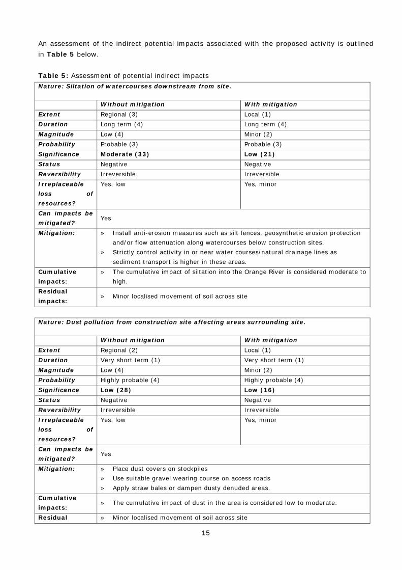
An assessment of the indirect potential impacts associated with the proposed activity is outlined in Table 5 below. Table 5: Assessment of potential indirect impacts Nature: Siltation of watercourses downstream from site.
Without mitigation With mitigation Extent Regional (3) Local (1) Duration Long term (4) Long term (4) Magnitude Low (4) Minor (2) Probability Probable (3) Probable (3) Significance Moderate (33) Low (21) Status Negative Negative Reversibility Irreversible Irreversible Irreplaceable loss of resources?
Yes, low Yes, minor
Can impacts be mitigated?
Yes
Mitigation: » Install anti-erosion measures such as silt fences, geosynthetic erosion protection and/or flow attenuation along watercourses below construction sites.
» Strictly control activity in or near water courses/natural drainage lines as sediment transport is higher in these areas.
Cumulative impacts:
» The cumulative impact of siltation into the Orange River is considered moderate to high.
Residual impacts:
» Minor localised movement of soil across site
Nature: Dust pollution from construction site affecting areas surrounding site.
Without mitigation With mitigation Extent Regional (2) Local (1) Duration Very short term (1) Very short term (1) Magnitude Low (4) Minor (2) Probability Highly probable (4) Highly probable (4) Significance Low (28) Low (16) Status Negative Negative Reversibility Irreversible Irreversible Irreplaceable loss of resources?
Yes, low Yes, minor
Can impacts be mitigated?
Yes
Mitigation: » Place dust covers on stockpiles » Use suitable gravel wearing course on access roads » Apply straw bales or dampen dusty denuded areas.
Cumulative impacts:
» The cumulative impact of dust in the area is considered low to moderate.
Residual » Minor localised movement of soil across site

16
impacts:
4.3.3. Impact statement The potential impacts on the geological environment associated with the proposed activity range from a low to moderate significance. A significant percentage of the proposed development is located in areas underlain by fine grained soils of the Gordonia Formation that are potentially sensitive to water erosion. The low annual rainfall does reduce the risk of erosion but effective implementation of mitigating measures must still be implemented in order to manage potential erosion, as well as other impacts, to a level deemed to be acceptable by the ECO. More detail regarding the soil types, thicknesses and erosion potential of the site can be obtained from the geotechnical investigations. The cumulative impact on the geological environment is generally considered low to moderate due to the localised and scattered nature of the proposed activity and the scarcity of development near the site. Increased siltation along watercourses feeding into the Orange River, as a result of agriculture and other human related activity in this catchment area, results in a potentially high cumulative impact on the catchment area. 4.3.4. Alternatives There are no site alternatives under consideration. The positioning of the infrastructure within the proposed site is determined by several factors, including the solar resources required for the effective operation of the plant, the proximity to existing infrastructure and water resources (Orange River) and the various environmental sensitivities that are identified during the scoping process. The only alternatives under consideration are concentrating solar power facilities with or without storage capacity on the site. In terms of potential impacts on the geological environment on the site under consideration, the benefits of the proposed activity are deemed to outweigh the potential impacts if appropriate mitigating measures that are provided in the EMP are diligently adhered to. 5. ENVIRONMENTAL MANAGEMENT PLAN (EMP) GUIDELINES FOR EARTHWORKS Negative impacts can be mitigated to a large degree by the implementation of an appropriate and effective EMP. The following generic guidelines relate specifically to the earthworks contract: 5.1. Earthworks 1. Prior to earthworks (including site clearance) starting on the site, a plant search and rescue
operation shall be undertaken as per the requirements set out in the EMP. 2. All earthworks shall be undertaken in such a manner so as to minimise the extent of any
impacts caused by such activities. 3. Defined access routes to and from the area of operations as well as around the area of
operation shall be detailed in a method statement for approval by the Site Manager.

17
4. No equipment associated with the activity shall be allowed outside of these areas unless expressly permitted by the Site Manager.
5. Mechanical methods of rock breaking, including hydraulic breakers, pneumatic drills or jackhammers, have noise and dust impacts, and must be addressed in the EMP.
6. Residents shall be notified at least one week prior to these activities commencing, and their concerns addressed.
7. Chemical breaking shall require a method statement approved by the Engineer’s Representative (ER).
5.2. Topsoil 1. Prior to construction, the topsoil areas to be disturbed should be stripped to a depth to be
confirmed by the ER and ECO and set aside for spreading to all areas to be reinstated after the construction. Temporary topsoil stock piles must be covered with net, shade cloth or straw bales to protect them.
2. Once all grades have been finalised and prepared, topsoil should be spread evenly to all affected areas to be re-vegetated.
5.3. Erosion and sedimentation control 1. Construction activity within a 32m buffer of the centreline of any natural drainage line can
only be undertaken with permission from the Dept of Environmental Affairs and/or Dept Water Affairs and must be subject to strict control by the ECO. No water-course is to be diverted or blocked/backfilled without the permission from relevant authorities. Similarly, the crossing of drainage lines with access roads (and the construction of culverts) is only to be undertaken with necessary authority from relevant authorities.
2. During construction the contractor shall protect areas susceptible to erosion by installing necessary temporary and permanent drainage works as soon as possible and by taking other measures necessary to prevent the surface water from being concentrated in streams and from scouring the slopes, banks or other areas.
3. A method statement shall be developed and submitted to the ER to deal with erosion issues prior to bulk earthworks operations commencing.
4. Any erosion channels developed during the construction period or during the vegetation establishment period shall be backfilled and compacted and the areas restored to a proper condition.
5. Stabilisation of cleared areas to prevent and control erosion shall be actively managed. The method of stabilisation shall determine in consultation with the ECO. Consideration and provision shall be made for the following methods (or combination): a) Brush cut packing b) Mulch or chip cover c) Straw stabilising d) Watering e) Planting/sodding f) Hand seed-sowing g) Hydroseeding h) Soil binders and anti erosion compounds

18
i) Gabion bolsters & mattresses for flow attenuation j) Geofabric k) Hessian cover l) Log/ pole fencing
6. Traffic and movement over stabilised areas shall be restricted and controlled and damage to stabilised areas shall be repaired and maintained to the satisfaction of the ECO.
7. Anti-erosion compounds shall consist of all organic or inorganic material to bind soil particles together and shall be a proven product able to suppress dust and erosion. The application rate shall conform to the manufacturer’s recommendations. The material used shall be approved by the ECO.
5.4. Blasting (If required) 1. A current and valid authorisation shall be obtained from the relevant authorities and copied to
the ER prior to any blasting activity. 2. A method statement shall be required for any blasting related activities. 3. All laws and regulations applicable to blasting activities shall be adhered to at all times. 4. A qualified and registered blaster shall supervise all blasting and rock splitting operations at
all times. 5. The contractor shall ensure that appropriate pre-blast monitoring records are in place (i.e.
photographic and inspection records of structures in close proximity to the blast area). 6. The contractor shall allow for good quality vibration monitoring equipment and record
keeping on site at all times during blasting operations. 7. The contractor shall ensure that emergency services are notified, in writing, a minimum of 24
hours prior to any blasting activities commencing on site. 8. The contractor shall take necessary precautions to prevent damage to special features and
the general environment, which includes the removal of fly-rock. Environmental damage caused by blasting / drilling shall be repaired at the contractor’s expense to the satisfaction of the ER.
9. The contractor shall ensure that adequate warning is provided immediately prior to all blasting. All signals shall also be clearly given.
10. The contractor shall use blast mats for cover material during blasting. Topsoil may not be used as blast cover.
11. During demolition the contractor shall ensure, where possible that trees in the area are not damaged.
12. Appropriate blast shaping techniques shall be employed to aid in the landscaping of blast areas, and a method statement to be approved by the ER, shall be required in this regard.
13. At least one week prior to blasting, the relevant occupants/owners of surrounding land shall be notified by the contractor and any concerns addressed. Buildings within the potential damaging zone of the blast shall be surveyed preferably with the owner present and any cracks or latent defects pointed out and recorded either using photographs or video. Failing to do so shall render the contractor fully liable for any claim of whatsoever nature, which may arise. The contractor shall indemnify the employer in this regard.
19
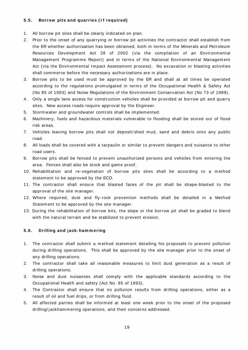
5.5. Borrow pits and quarries (If required) 1. All borrow pit sites shall be clearly indicated on plan. 2. Prior to the onset of any quarrying or borrow pit activities the contractor shall establish from
the ER whether authorisation has been obtained, both in terms of the Minerals and Petroleum Resources Development Act 28 of 2002 (via the compilation of an Environmental Management Programme Report) and in terms of the National Environmental Management Act (via the Environmental Impact Assessment process). No excavation or blasting activities shall commerce before the necessary authorizations are in place.
3. Borrow pits to be used must be approved by the ER and shall at all times be operated according to the regulations promulgated in terms of the Occupational Health & Safety Act (No 85 of 1993) and Noise Regulations of the Environment Conservation Act (No 73 of 1989).
4. Only a single lane access for construction vehicles shall be provided at borrow pit and quarry sites. New access roads require approval by the Engineer.
5. Stormwater and groundwater controls shall be implemented. 6. Machinery, fuels and hazardous materials vulnerable to flooding shall be stored out of flood
risk areas. 7. Vehicles leaving borrow pits shall not deposit/shed mud, sand and debris onto any public
road. 8. All loads shall be covered with a tarpaulin or similar to prevent dangers and nuisance to other
road users. 9. Borrow pits shall be fenced to prevent unauthorized persons and vehicles from entering the
area. Fences shall also be stock and game proof. 10. Rehabilitation and re-vegetation of borrow pits sites shall be according to a method
statement to be approved by the ECO. 11. The contractor shall ensure that blasted faces of the pit shall be shape-blasted to the
approval of the site manager. 12. Where required, dust and fly-rock prevention methods shall be detailed in a Method
Statement to be approved by the site manager. 13. During the rehabilitation of borrow bits, the slope or the borrow pit shall be graded to blend
with the natural terrain and be stabilized to prevent erosion. 5.6. Drilling and jack-hammering 1. The contractor shall submit a method statement detailing his proposals to prevent pollution
during drilling operations. This shall be approved by the site manager prior to the onset of any drilling operations.
2. The contractor shall take all reasonable measures to limit dust generation as a result of drilling operations.
3. Noise and dust nuisances shall comply with the applicable standards according to the Occupational Health and safety (Act No. 85 of 1993).
4. The Contractor shall ensure that no pollution results from drilling operations, either as a result of oil and fuel drips, or from drilling fluid.
5. All affected parties shall be informed at least one week prior to the onset of the proposed drilling/jackhammering operations, and their concerns addressed.

20
6. Drill coring with water or coolant lubricants shall require a method statement approved by the Site Manager.
7. Any areas or structures damaged by the drilling and associated activities shall be rehabilitated by the contractor to the satisfaction of the site manager.
5.7. Trenching 1. Trenching shall be kept to a minimum through the use of single trenches for multiple service
provision. 2. The planning and selection of trench routes shall be undertaken in liaison with the ER and
cognisance shall be given to minimising the potential for soil erosion. 3. Trench routes with permitted working areas shall be clearly defined and marked with painted
stakes prior to excavation. 4. The stripping and separation of topsoil shall occur as stipulated by the ER. Soil shall be
stockpiled for use as backfilling as directed by the ER. 5. Trench lengths shall be kept as short as practically possible before backfilling and
compacting. 6. Trenches shall be backfilled to the same level as (or slightly higher to allow for settlement)
the surrounding land surface to minimise erosion. Excess soil shall be stockpiled in an area approved by the engineer.
7. Immediately after backfilling, trenches and associated disturbed working areas shall be planted with a suitable plant species and regularly watered. Where there is a particularly high erosion risk, a fabric such as Geojute (biodegradable) shall be used in addition to planting.

21
5.8. Dust
1. The contractor shall be solely responsible for the control of dust arising from the contractor’s
operations and for any costs against the employer for damages resulting from dust. 2. The contractor shall take all reasonable measures to minimise the generation of dust as a
result of construction activities to the satisfaction of the site manager. 3. Removal of vegetation shall be avoided until such time as soil stripping is required and
similarly exposed surfaces shall be re-vegetated or stabilised as soon as is practically possible.
4. Excavation, handling and transport of erodible materials shall be avoided under high wind conditions or when a visible dust plume is present.
5. During high wind conditions the site manager will evaluate the situation and make recommendations as to whether dust damping measures are adequate, or whether working will cease altogether until the wind speed drops to an acceptable level.
6. Where possible, soil stockpiles shall be located in sheltered areas where they are not exposed to the erosive effects of the wind. Where erosion of stockpiles becomes a problem, erosion control measures shall be implemented at the discretion of the site manager.
7. Vehicle speeds shall not exceed 40km/h along dust roads or 20km/h when traversing unconsolidated and non-vegetated areas.
8. Appropriate dust suppression measures shall be used when dust generation as unavoidable, e.g. dampening with water, particularly during prolonged periods of dry weather in summer. Such measures shall also include the use of temporary stabilising measures (e.g. chemical soil binders, straw, brush packs, clipping etc.)
9. Straw stabilisation shall be applied at a rate of one bale/ 10m2 and harrowed into the top 100mm of top material for all completed earthworks.
5.9. Imported materials and stockpiles 1. Imported materials shall be free of weeds, litter and contaminants. 2. Sources of imported material shall be listed and approved by the ER on site. 3. The contractor shall provide samples to the ER for approval. 4. Stockpile areas shall be approved by the ER before any stockpiling commences. 5.10. Summary of objectives and performance monitoring A summary of the project components, potential impacts, mitigating measures and performance monitoring is outlined in Table 6. Table 6: Summary of objectives of the EMP OBJECTIVE: Soil and rock degradation and erosion control The geological environment including bedrock, soil cover and landforms must be preserved as far as possible to minimise unforeseen impacts on the surrounding environment.

22
A set of strictly adhered mitigation measures are required to effectively limit the impact on the geological environment. The proposed disturbance areas - where construction activity is likely to occur - are the focus of the mitigation measures laid out below.
Project component/s
Solar energy infrastructure (CSP towers/linear Fresnels/parabolic troughs) Access roads Substation linking the facility to the electricity grid Underground cabling Power lines
Potential Impact Soil and rock removal Soil mixing, wetting, stockpiling, compaction Soil pollution Accelerated soil erosion Increased siltation along drainage systems Increased run-off over the site Dust pollution
Activity/risk source
Construction activity – earthworks & transportation across site Machinery, chemicals and human waste – soil pollutants Rainfall - water erosion of disturbed areas Wind erosion of disturbed areas
Mitigation: Target/Objective
To minimise size of construction disturbance areas To minimise destructive activity within disturbance areas & prevent
unnecessary activity outside of disturbance areas To minimise soil degradation (removal, excavation, mixing, wetting,
compaction, pollution, erosion, etc.) To minimise deposition of soil into drainage lines To minimise dust pollution
Mitigation: Action/control Responsibility Timeframe
Identify areas of high erosion risk (drainage lines/watercourses). Only special works to be undertaken in these areas to be authorised by ECO and Engineer’s representative (ER)
ECO/ER/Contractor Before and during construction
Identify disturbance areas for general construction work and restrict construction activity to these areas.
ECO/ER/Contractor Before and during construction
Prevent unnecessary destructive activity within disturbance areas (prevent over-excavations and double handling)
ECO/ER/Contractor Before and during construction
Access roads to be carefully planned and constructed to minimise the impacted area and prevent unnecessary degradation of soil. Special attention to be given to roads that cross drainage lines and roads on steep slopes (to prevent unnecessary cutting and filling operations).
ECO/ER/Contractor Before and during construction
Dust control on construction site: Wetting or covering of cleared areas.
Contractor During construction
Minimise removal of vegetation which aids soil stability. ECO/Contractor During construction
Rehabilitate disturbance areas as soon as an area is vacated.
Contractor During and after construction
Soil conservation: Stockpile topsoil for re-use in Contractor Before and during
23
Mitigation: Action/control Responsibility Timeframe
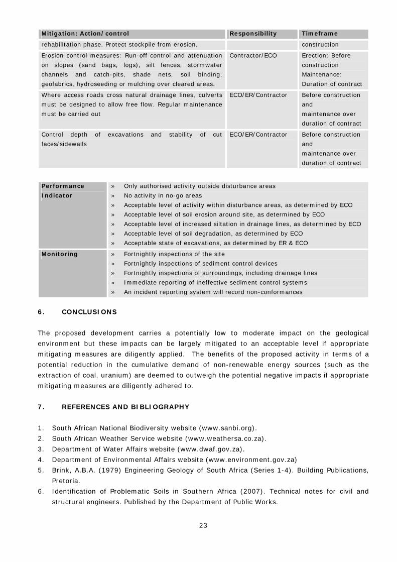
rehabilitation phase. Protect stockpile from erosion. construction
Erosion control measures: Run-off control and attenuation on slopes (sand bags, logs), silt fences, stormwater channels and catch-pits, shade nets, soil binding, geofabrics, hydroseeding or mulching over cleared areas.
Contractor/ECO Erection: Before construction Maintenance: Duration of contract
Where access roads cross natural drainage lines, culverts must be designed to allow free flow. Regular maintenance must be carried out
ECO/ER/Contractor Before construction and maintenance over duration of contract
Control depth of excavations and stability of cut faces/sidewalls
ECO/ER/Contractor Before construction and maintenance over duration of contract
Performance Indicator
» Only authorised activity outside disturbance areas » No activity in no-go areas » Acceptable level of activity within disturbance areas, as determined by ECO » Acceptable level of soil erosion around site, as determined by ECO » Acceptable level of increased siltation in drainage lines, as determined by ECO » Acceptable level of soil degradation, as determined by ECO » Acceptable state of excavations, as determined by ER & ECO
Monitoring » Fortnightly inspections of the site » Fortnightly inspections of sediment control devices » Fortnightly inspections of surroundings, including drainage lines » Immediate reporting of ineffective sediment control systems » An incident reporting system will record non-conformances
6. CONCLUSIONS The proposed development carries a potentially low to moderate impact on the geological environment but these impacts can be largely mitigated to an acceptable level if appropriate mitigating measures are diligently applied. The benefits of the proposed activity in terms of a potential reduction in the cumulative demand of non-renewable energy sources (such as the extraction of coal, uranium) are deemed to outweigh the potential negative impacts if appropriate mitigating measures are diligently adhered to. 7. REFERENCES AND BIBLIOGRAPHY 1. South African National Biodiversity website (www.sanbi.org). 2. South African Weather Service website (www.weathersa.co.za). 3. Department of Water Affairs website (www.dwaf.gov.za). 4. Department of Environmental Affairs website (www.environment.gov.za) 5. Brink, A.B.A. (1979) Engineering Geology of South Africa (Series 1-4). Building Publications,
Pretoria. 6. Identification of Problematic Soils in Southern Africa (2007). Technical notes for civil and
structural engineers. Published by the Department of Public Works.

24
7. Mucina, L., Rutherford, M.C. & Powrie, L.W. (eds) 2005. Vegetation map of South Africa, Lesotho and Swaziland, 1:1 000 000 scale sheet maps. South African National Biodiversity Institute, Pretoria.
8. Garland, G., Hoffman, T. And Todd, S. Soil degradation (in Hoffman, T., Todd, S., Ntshona, Z. And Turner, S. (eds) (1999). Land degradation in SA, Chapter 6, NBRI, Kistenbosch.
9. 1:250 000 Geological map Sheet 2820 Upington. Geological Survey of South Africa. Government Printer.
10. Wienert, H. H. (1980). The Natural Road Construction Materials of Southern Africa. H&R Academia Publ., Pretoria, 298pp.
11. SACS (1980). Stratigraphy of South Africa. Handbook 8, Geological Survey, Department of Mineral and Energy Affairs, Government Printer, 690pp.
12. Savannah Environmental (2011) Draft Scoping Report: Proposed Ilanga Solar Thermal Power Plant as part of the future Karoshoek Solar Thermal Park, near Upington, Northern Cape Province (DEA Ref: 12/12/20/2056).