GEOHM C-GB int. - Farnell element14 · In the interest of safety, maximum test voltage at the...
36
GEOHM ® C-GB int. Earth Tester 3-349-089-03 8/9.06 Operating Instructions
Transcript of GEOHM C-GB int. - Farnell element14 · In the interest of safety, maximum test voltage at the...

GEOHM®C-GB int.Earth Tester
3-349-089-038/9.06
Operating Instructions

2 GMC-I Gossen-Metrawatt GmbH
GEOHM®C Measuring and Test Instrument GEOHM®C Control and Display Unit
LIMIT RH>maxNetz
Mains
START
Control and
Keys for the Selection of Basic
LCD
Line or interference voltage at m
easurement input
Probe or auxiliary e
arth electrode resist
ance
Limit value vio
lation
Left Switch Contact:Displays Basic Functions,
Toggle SwitchMiddle Switch Contact:
Start Measurement
Functions and Sub-Functions
Right Switch Contact:Displays Basic Functions,
Scrolling from Right to Left Scrolling from Left to Right
Battery Level Display
Interference voltage too high (cannot be compensated)
Signal Lamps
S
(menu driven operation)The desired menu functions can be displayed with the
and keys.
The scroll bar indicates which menu is currently active.
Carry
ing S
trap
Clasp
Display Unit
UstörUnoise
HESE
RS>max
P2 C2P1C1
Jacks for:Z501D External battery chargerE/C1 Earth electrodeES/P1 Earth probe cable (4-pole measurement)S/P2 ProbeH/C2 Auxiliary earth electrode
Z501
D
greater than allowed
internationalmarking
Infrared Interface Interface Adapter(for plug-on instructionssee page 3)
GMC-I Gossen-Metrawatt GmbH 3
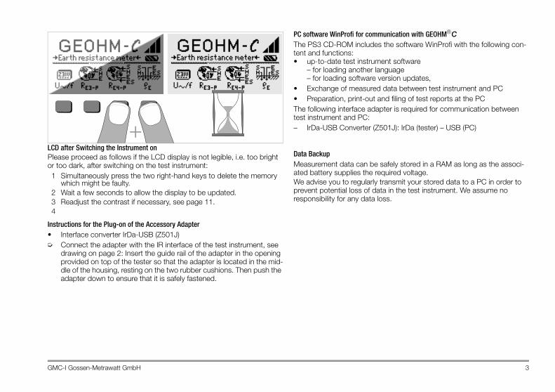
LCD after Switching the Instrument onPlease proceed as follows if the LCD display is not legible, i.e. too bright or too dark, after switching on the test instrument:1 Simultaneously press the two right-hand keys to delete the memory
which might be faulty.2 Wait a few seconds to allow the display to be updated.3 Readjust the contrast if necessary, see page 11.4
Instructions for the Plug-on of the Accessory Adapter• Interface converter IrDa-USB (Z501J)➭ Connect the adapter with the IR interface of the test instrument, see
drawing on page 2: Insert the guide rail of the adapter in the opening provided on top of the tester so that the adapter is located in the mid-dle of the housing, resting on the two rubber cushions. Then push the adapter down to ensure that it is safely fastened.
PC software WinProfi for communication with GEOHM®CThe PS3 CD-ROM includes the software WinProfi with the following con-tent and functions:• up-to-date test instrument software
– for loading another language– for loading software version updates,
• Exchange of measured data between test instrument and PC• Preparation, print-out and filing of test reports at the PCThe following interface adapter is required for communication between test instrument and PC:– IrDa-USB Converter (Z501J): IrDa (tester) – USB (PC)
Data BackupMeasurement data can be safely stored in a RAM as long as the associ-ated battery supplies the required voltage.We advise you to regularly transmit your stored data to a PC in order to prevent potential loss of data in the test instrument. We assume no responsibility for any data loss.
+

Contents Page Contents Page
4 GMC-I Gossen-Metrawatt GmbH
1 Applications .....................................................................................5
2 Safety Features and Precautions ....................................................6
3 Terminology ....................................................................................7
4 Initial Start-Up .................................................................................84.1 Switching the Instrument On and Off ................................................................84.2 Battery Test ....................................................................................................84.3 Installing and Replacing Batteries .....................................................................84.4 Additional User Interface Languages ................................................................84.5 Selecting Menus and Configuring Basic Settings ..............................................94.6 Downloading a Software Update, Managing Report Data .................................12
5 Operation .......................................................................................155.1 Display Functions ..........................................................................................155.2 Online Help ...................................................................................................155.3 Voltage Measurement ...................................................................................165.4 Earth Resistance Measurements in General ....................................................165.4.1 Configuring the Measuring Range – RANGE Function ......................................175.4.2 Setting a Limit Value – LIMIT Function ...........................................................185.5 Measuring Earthing Resistance ......................................................................185.5.1 Measuring Circuit Setup, Measuring Instructions .............................................185.6 Measuring Soil Resistivity ..............................................................................225.6.1 Geologic Surveys ..........................................................................................225.6.2 Calculating Dissemination Resistance ............................................................235.7 Measuring Ohmic Resistance ........................................................................245.7.1 2-Wire Connection ........................................................................................245.7.2 4-Wire Connection ........................................................................................24
6 Database Function ........................................................................256.1 Creating a Data Record – Data Function ........................................................ 256.2 Saving Measured Values to Memory – STORE Function .................................. 266.3 Querying Data Records – View Function ......................................................... 276.3.1 Deleting a Data Record from within a Memory Address – View Function .......... 276.3.2 Deleting a Memory Address – Data Function .................................................. 276.3.3 Delete All Memory Addresses – Data Function ............................................... 286.4 Print Function ............................................................................................... 28
7 Characteristic Values ....................................................................29
8 Maintenance .................................................................................318.1 Housing ....................................................................................................... 318.2 Battery Operation ......................................................................................... 318.3 Fuses .......................................................................................................... 32
9 Repair and Replacement Parts Service,DKD Calibration Lab and Rental Instrument Service .....................33
10 Product Support ............................................................................33
GMC-I Gossen-Metrawatt GmbH 5
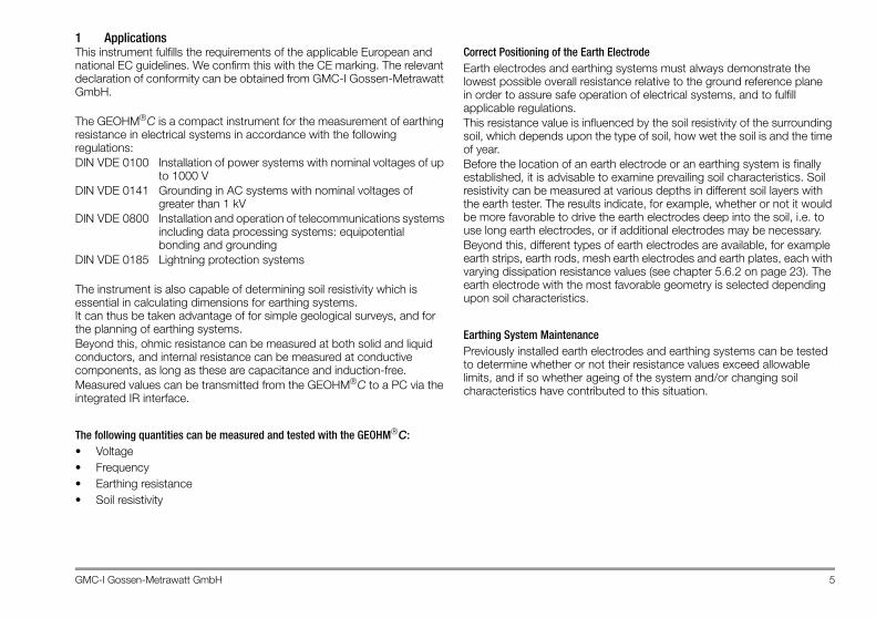
1 ApplicationsThis instrument fulfills the requirements of the applicable European and national EC guidelines. We confirm this with the CE marking. The relevant declaration of conformity can be obtained from GMC-I Gossen-Metrawatt GmbH.
The GEOHM®C is a compact instrument for the measurement of earthing resistance in electrical systems in accordance with the following regulations:DIN VDE 0100 Installation of power systems with nominal voltages of up
to 1000 VDIN VDE 0141 Grounding in AC systems with nominal voltages of
greater than 1 kVDIN VDE 0800 Installation and operation of telecommunications systems
including data processing systems: equipotential bonding and grounding
DIN VDE 0185 Lightning protection systems
The instrument is also capable of determining soil resistivity which is essential in calculating dimensions for earthing systems. It can thus be taken advantage of for simple geological surveys, and for the planning of earthing systems.Beyond this, ohmic resistance can be measured at both solid and liquid conductors, and internal resistance can be measured at conductive components, as long as these are capacitance and induction-free.Measured values can be transmitted from the GEOHM®C to a PC via the integrated IR interface.
The following quantities can be measured and tested with the GEOHM®C:• Voltage• Frequency• Earthing resistance• Soil resistivity
Correct Positioning of the Earth ElectrodeEarth electrodes and earthing systems must always demonstrate the lowest possible overall resistance relative to the ground reference plane in order to assure safe operation of electrical systems, and to fulfill applicable regulations.This resistance value is influenced by the soil resistivity of the surrounding soil, which depends upon the type of soil, how wet the soil is and the time of year.Before the location of an earth electrode or an earthing system is finally established, it is advisable to examine prevailing soil characteristics. Soil resistivity can be measured at various depths in different soil layers with the earth tester. The results indicate, for example, whether or not it would be more favorable to drive the earth electrodes deep into the soil, i.e. to use long earth electrodes, or if additional electrodes may be necessary. Beyond this, different types of earth electrodes are available, for example earth strips, earth rods, mesh earth electrodes and earth plates, each with varying dissipation resistance values (see chapter 5.6.2 on page 23). The earth electrode with the most favorable geometry is selected depending upon soil characteristics.
Earthing System MaintenancePreviously installed earth electrodes and earthing systems can be tested to determine whether or not their resistance values exceed allowable limits, and if so whether ageing of the system and/or changing soil characteristics have contributed to this situation.
6 GMC-I Gossen-Metrawatt GmbH
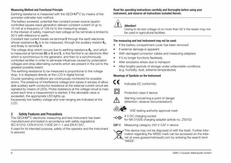
Measuring Method and Functional PrincipleEarthing resistance is measured with the GEOHM®C by means of the ammeter-voltmeter test method.The battery powered, potential-free constant power source (quartz-controlled square-wave generator) delivers constant current of up to 10 mA at a frequency of 128 Hz to the measuring ranges. In the interest of safety, maximum test voltage at the terminals is limited to 50 V with reference to earth. Constant test current travels via terminal E through the earth electrode whose resistance RE is to be measured, through the auxiliary resistor RH and finally to terminal H.The voltage drop which occurs due to earthing resistance RE, and which is measured at terminals ES or E and S, is first fed first to an electronic filter which is synchronous to the generator, and then to a synchronously controlled rectifier in order to eliminate influences caused by polarization voltages and stray alternating currents which are present in the soil to the greatest possible extent.The earthing resistance to be measured is proportional to the voltage drop. It is displayed directly at the LCD in digital format.Crucial operating conditions are continuously monitored for possible errors. The presence of interference voltage and values in excess of allow-able auxiliary earth conductor resistance at the external current circuit are signaled by means of LEDs. Probe resistance at the voltage circuit is mea-sured each time a measurement is started. If the allowable value is exceeded, the appropriate LED lights up. Excessively low battery voltage and over-ranging are indicated at the LCD.
2 Safety Features and PrecautionsThe GEOHM®C electronic measuring and test instrument has been manufactured and tested in accordance with safety regulations IEC 61010-1/EN 61010-1/VDE 0411-1 and EN 61557.If used for its intended purpose, safety of the operator and the instrument is assured.
Read the operating instructions carefully and thoroughly before using your instrument, and observe all instructions included therein.
Attention!!Owing to its test voltage of no more than 50 V the tester may not be used in agricultural facilities.
The measuring and test instrument may not be used:• If the battery compartment cover has been removed• If external damage is apparent• With damaged connector cables and measuring adapters• If it no longer functions flawlessly• After excessive stress due to transport• After lengthy periods of storage under unfavorable conditions
(e.g. humidity, dust, extreme temperatures)
Meanings of Symbols on the Instrument
Indicates EC conformity
Protection class II device
Warning concerning a point of danger(Attention: observe documentation!)
VDE testing authority approval mark
9 V DC charging socketfor NA 0100S charging adapter (article no. Z501D)
CAT I I Measuring category 250 V CAT I I device
This device may not be disposed of with the trash. Further infor-mation regarding the WEEE mark can be accessed on the Inter-net at www.gossenmetrawatt.com by entering the search term ’WEEE’.
!
–
GMC-I Gossen-Metrawatt GmbH 7
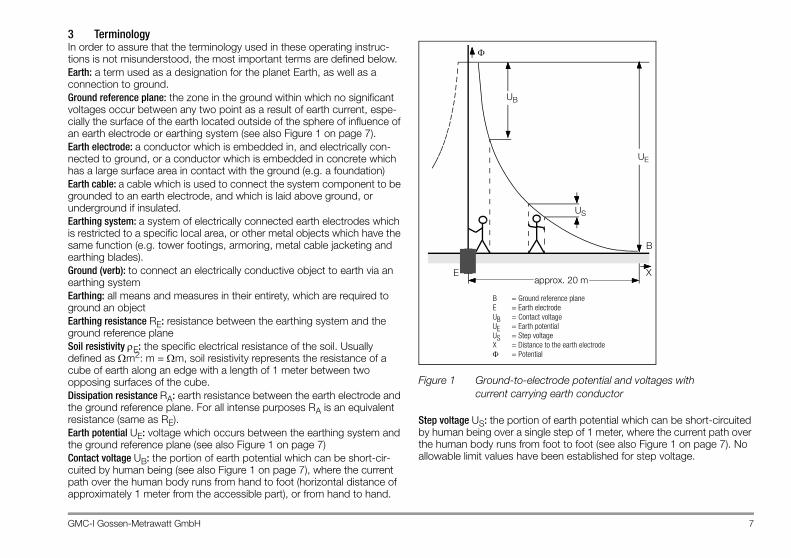
3 TerminologyIn order to assure that the terminology used in these operating instruc-tions is not misunderstood, the most important terms are defined below.Earth: a term used as a designation for the planet Earth, as well as a connection to ground.Ground reference plane: the zone in the ground within which no significant voltages occur between any two point as a result of earth current, espe-cially the surface of the earth located outside of the sphere of influence of an earth electrode or earthing system (see also Figure 1 on page 7).Earth electrode: a conductor which is embedded in, and electrically con-nected to ground, or a conductor which is embedded in concrete which has a large surface area in contact with the ground (e.g. a foundation)Earth cable: a cable which is used to connect the system component to be grounded to an earth electrode, and which is laid above ground, or underground if insulated.Earthing system: a system of electrically connected earth electrodes which is restricted to a specific local area, or other metal objects which have the same function (e.g. tower footings, armoring, metal cable jacketing and earthing blades).Ground (verb): to connect an electrically conductive object to earth via an earthing systemEarthing: all means and measures in their entirety, which are required to ground an objectEarthing resistance RE: resistance between the earthing system and the ground reference planeSoil resistivity ρE: the specific electrical resistance of the soil. Usually defined as Ωm2: m = Ωm, soil resistivity represents the resistance of a cube of earth along an edge with a length of 1 meter between two opposing surfaces of the cube.Dissipation resistance RA: earth resistance between the earth electrode and the ground reference plane. For all intense purposes RA is an equivalent resistance (same as RE).Earth potential UE: voltage which occurs between the earthing system and the ground reference plane (see also Figure 1 on page 7)Contact voltage UB: the portion of earth potential which can be short-cir-cuited by human being (see also Figure 1 on page 7), where the current path over the human body runs from hand to foot (horizontal distance of approximately 1 meter from the accessible part), or from hand to hand.
Figure 1 Ground-to-electrode potential and voltages withcurrent carrying earth conductor
Step voltage US: the portion of earth potential which can be short-circuited by human being over a single step of 1 meter, where the current path over the human body runs from foot to foot (see also Figure 1 on page 7). No allowable limit values have been established for step voltage.
B = Ground reference planeE = Earth electrodeUB = Contact voltageUE = Earth potentialUS = Step voltageX = Distance to the earth electrodeΦ = Potential
US
UB
Eapprox. 20 m
X
B
UE
Φ

8 GMC-I Gossen-Metrawatt GmbH
4 Initial Start-Up
4.1 Switching the Instrument On and Off
The instrument can be switched on by pressing any key.The instrument is switched off manually by simultaneously pressing and holding the two outermost softkeys.
4.2 Battery TestFive battery symbols ranging from depleted to fully charged continuously indicate the current battery level in the main menu.
4.3 Installing and Replacing BatteriesNew batteries must be installed before initial start-up, or when only one solid segment remains in the battery symbol.
Attention!!The instrument must be disconnected from the measuring circuit (mains) at all poles before the battery compartment is opened.
Four 1.5 V baby cells in accordance with IEC LR14 are required for operation of the GEOHM®C. Use alkaline-manganese batteries only.
Rechargeable NiCd or NiMH batteries may be used as well. Be absolutely sure to refer to chapter 8.2 on page 31 regarding the charging cycle and the charging adapter.Always replace the batteries in complete sets.Dispose of batteries in an environmentally sound fashion.➭ Loosen the two slotted screws at the battery compartment cover on
the housing rear panel and remove the cover.➭ Insert four 1.5 V baby cells making certain the they are poled in
accordance with the symbols. Insert the two batteries which are half covered by the housing first.
➭ Replace the cover and retighten the screws.
Attention!!The instrument may not be operated if the battery compartment cover has not been installed and properly tightened!
4.4 Additional User Interface LanguagesUser interface languages other than those included with the instrument can be uploaded with the help of a software update. Please ask for a list of currently available languages. All currently available languages are pro-posed for selection upon installation of WinProfi, see chapter 4.5.
ENTER
GMC-I Gossen-Metrawatt GmbH 9
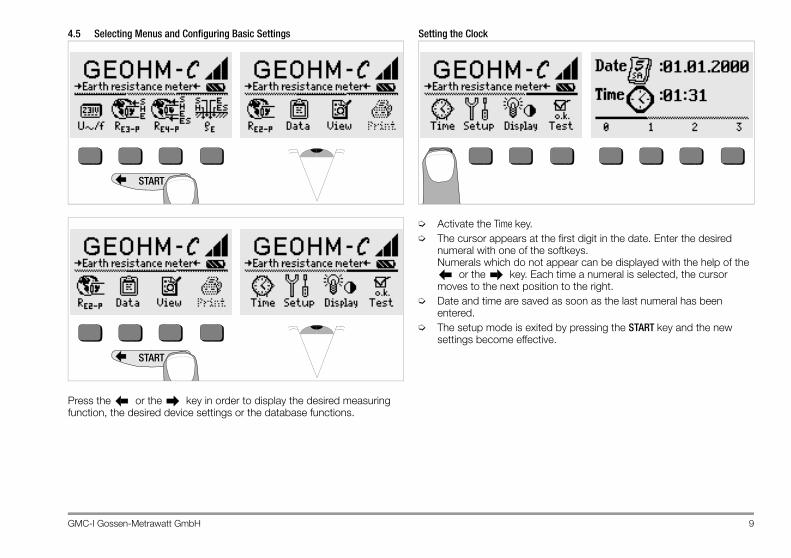
4.5 Selecting Menus and Configuring Basic Settings
Press the or the key in order to display the desired measuring function, the desired device settings or the database functions.
Setting the Clock
➭ Activate the Time key.➭ The cursor appears at the first digit in the date. Enter the desired
numeral with one of the softkeys. Numerals which do not appear can be displayed with the help of the
or the key. Each time a numeral is selected, the cursor moves to the next position to the right.
➭ Date and time are saved as soon as the last numeral has been entered.
➭ The setup mode is exited by pressing the START key and the new settings become effective.
START
START

10 GMC-I Gossen-Metrawatt GmbH
Default Settings – Last Used SettingsA selection can be made here as to whether the menus will be displayed according to the default settings, or if the last opened menus should be displayed.
➭ Press the Setup key.➭ Press the Default key if necessary:
on ✓ Settings such as Ton (20 sec.) are reset to the default settings when the instrument is switched on.
off ✓ The last used settings remain effective when the instrument is switched on.
➭ Exit the setup menu by pressing the key.
Setting On-Time, Manual Shutdown
➭ Press the Setup key.➭ Press the Ton key and then the 10sec, 20sec, 30sec or 60sec key depend-
ing upon the desired duration after which the test instrument should switch off automatically. Additional setting options can be displayed by activating the scroll bar with the or the key. If the “>>>>>” setting is selected, no automatic shutdown occurs. The selected setting has a substantial influence on battery service life.
➭ Exit the setup menu by pressing the key.

GMC-I Gossen-Metrawatt GmbH 11
Background Illumination and Contrast
➭ Press the Display key.➭ In order to extend battery service life, display illumination can be
switched off entirely. Press the corresponding softkey to this end.
If LCD illumination is activated (ON), it is automatically switched off several seconds after the last key has been activated in order to extend battery service life. As soon as a key is activated again, illumination is switched back on.➭ Contrast can be optimized with the two keys at the far right.➭ The setup menu is exited by pressing the START key, and the selected
settings become effective.
Self-Test
➭ The self-test is started from the main menu with the Test key. The test has a duration of several minutes.
The following information is displayed in the two headers: Type/Cal: Device type / date of last calibration (balancing)Version: Software version and issue date
Self-tests for items Chksum through LED are performed automatically, one after the other, and are checked off or marked with a horizontal dash if they are not passed.
Chksum1/2: Status display for internal testing (each test must be completed with a check mark). If not, the measuring and test instrument may no longer be used. Please contact our service center in this case.
Relays: Each relay is switched twice.LED: The RH/RS and LIMIT LEDs each blink twice in red, and the
Netz/Mains LED blinks twice in green and twice in red. The Unoise lamp blinks twice in red.
As soon as the tests in the left-hand column have been completed, the following tests must be started manually.➭ Illum: Press the Test key twice in order to activate and deactivate
display illumination.
low highContrast
off onLCD Illumination

12 GMC-I Gossen-Metrawatt GmbH
➭ Display: Press the Test key after each test pattern has been displayed in order test the display elements.
➭ Keytest: Perform the key test by pressing each of the softkeys once, and by pressing the start key once in each of its three positions. The keys appear filled in at the key pictograph after they have been tested.
Individual tests can be skipped by pressing the skip key before starting the respective test. These tests are then identified with a horizontal dash, as is also the case for tests which have not been passed.
4.6 Downloading a Software Update, Managing Report DataIf you require an updated test instrument software, it can be downloaded with the help of WinProfi PC software. The data file with the desired soft-ware version is transmitted to the test instrument via the serial interface. The previously installed language is overwritten.
NoteThis software includes all of the functions required for communica-tions between the GEOHM®C and the PC. A description of the program is included in the online user’s manual which can be accessed from WinProfi.
Programm WinProfi
A Install WinProfi to the PC and Start the Program➭ First install the software to your PC.
Insert the CD into the CD drive, for example drive E.Execute the file E:\GMCDEMO
➭ Click the globe icon.➭ Follow the instructions which appear at the monitor.The program is added to your START menu after installation.
➭ Establish a connection between your PC and the GEOHM®C test in-strument by using interface adapter IrDa-USB converter.
➭ Start WinProfi.➭ Switch on the test instrument.➭ Set the on-time period of the GEOHM®C to „>>>>>“, to give you
enough time for adjusting the settings in WinProfi before the test in-strument switches off again automatically, see chapter 4.5.
Display or print out online user’s manualThe online manual contains information concerning the software which is not included in these operating instructions.

GMC-I Gossen-Metrawatt GmbH 13
B Prerequisites for Software Update or Data Exchange➭ Find the interface to which the GEOHM®C is connected.
NoteAlways start this function first, before performing an update or chang-ing report templates. After starting this function, WinProfi loads the report files specifically necessary for the connected instrument. Due to the fact that WinProfi has been created for use with several types of test instruments, incorrect test reports may otherwise be loaded, or erroneous options may be made available.
➭ Query information regarding current software version
C Transmission of a Software Update to the Test Instrument
➭ PC: Select the Update All function from the Update menu. Follow the instructions which appear at the monitor.
Depending upon the utilized PC, transmission takes from 1 to 2 minutes.
The NETZ/MAINS LED of the GEOHM®C test instrument lights up green and indicates that the instrument is ready to receive data. If the PC and the test instrument are correctly synchronized, the same LED lights up yellow. During programming sequences, the LIMIT and RS>max/RH>max LEDs light up red and the NETZ/MAINS LED lights up yellow in alternating order. Upon completion of data transmission, the NETZ/MAINS LED briefly lights up green, afterwards all LEDs go out.The message „Transmission done“ appears on the computer screen
Attention!!The instrument may not, under any circumstances, be switched off during transmission, nor may the connection between the in-strument and the PC be interrupted!
14 GMC-I Gossen-Metrawatt GmbH
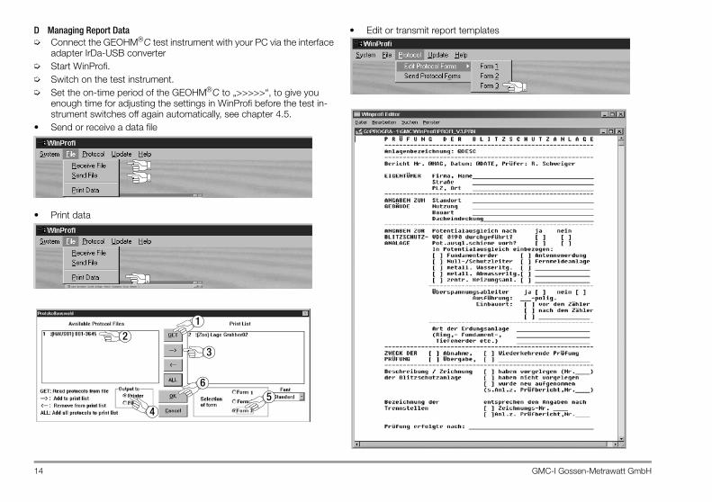
D Managing Report Data➭ Connect the GEOHM®C test instrument with your PC via the interface
adapter IrDa-USB converter➭ Start WinProfi.➭ Switch on the test instrument.➭ Set the on-time period of the GEOHM®C to „>>>>>“, to give you
enough time for adjusting the settings in WinProfi before the test in-strument switches off again automatically, see chapter 4.5.
• Send or receive a data file
• Print data
• Edit or transmit report templates
6
3
5
21
4

GMC-I Gossen-Metrawatt GmbH 15
5 Operation
5.1 Display FunctionsThe following items are displayed at the LCD:• Measured values with abbreviated designations and units of measure• The selected function• Error messagesDuring measuring sequences which are executed automatically, mea-sured values are saved and displayed in digital format until the next measuring sequence is started, or until the instrument is shut down automatically.If the upper measuring range limit is exceeded, the upper limit appears in the display preceded by the “>” symbol (greater than) in order to indicate over-ranging.
Attention!!Earthing resistance measurements are not valid if any of the following displays indicate the occurrence of an error before or during measurement, or if low battery voltage is indicated.
LED Functions
5.2 Online HelpAppropriate online help texts can be displayed at the LCD for each of the basic functions and sub-functions, after the respective function has been selected in the corresponding menu.➭ Press the key to query online help.
Press any key to exit the help function.
LED lights up red
Measuring Func-tion Significance Remedy
UStör/Unoise Interference voltage
Interference voltage in the soil to be measured exceeds the maximum value which can be compensated for by the earth tester.
Wait until the interference voltage clears on its own, or insert the test spike at a different location.
Netz/Mains Voltage Line voltage is present.
LIMIT Earthing resistance
RE is greater than the selected limit value.
Check the limit value, improve earthing.
RS > max Probe resistance during power-up
Resistance exceeded at the external current circuit.Cause: open circuit, poor connection between test cable and auxiliary earth electrode or high resistance in the ground in proximity to the auxiliary earth electrode
– Reposition the spike– Moisten the soil around the auxiliary
earth electrode– Use an auxiliary spike
RH > max Auxiliary earth electrode resistance
i
16 GMC-I Gossen-Metrawatt GmbH
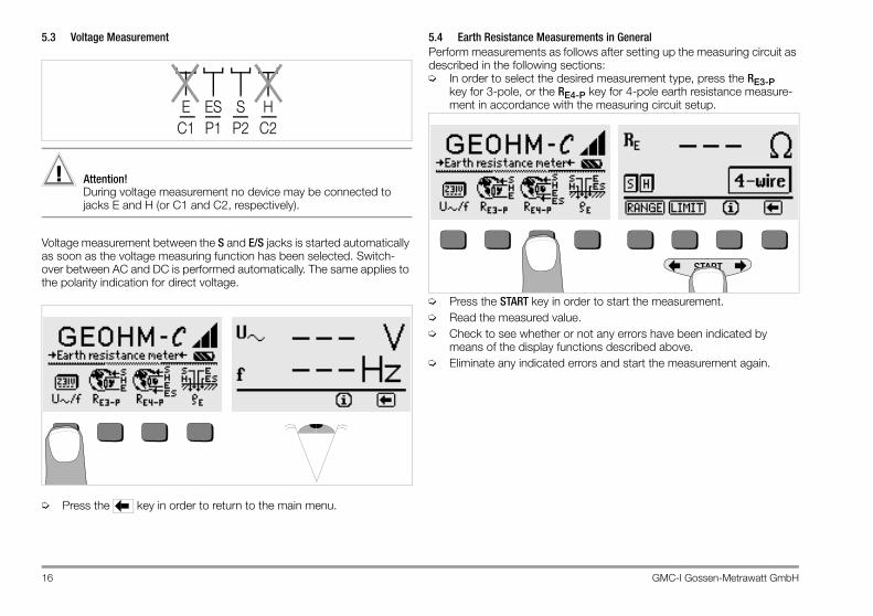
5.3 Voltage Measurement
Attention!!During voltage measurement no device may be connected to jacks E and H (or C1 and C2, respectively).
Voltage measurement between the S and E/S jacks is started automatically as soon as the voltage measuring function has been selected. Switch-over between AC and DC is performed automatically. The same applies to the polarity indication for direct voltage.
➭ Press the key in order to return to the main menu.
5.4 Earth Resistance Measurements in General Perform measurements as follows after setting up the measuring circuit as described in the following sections:➭ In order to select the desired measurement type, press the RE3-P
key for 3-pole, or the RE4-P key for 4-pole earth resistance measure-ment in accordance with the measuring circuit setup.
➭ Press the START key in order to start the measurement.➭ Read the measured value.➭ Check to see whether or not any errors have been indicated by
means of the display functions described above.➭ Eliminate any indicated errors and start the measurement again.
S HESEP2 C2P1C1
START

GMC-I Gossen-Metrawatt GmbH 17
5.4.1 Configuring the Measuring Range – RANGE FunctionAutomatic Measuring Range SelectionIf automatic measuring range selection is used, the instrument selects the highest possible current it is capable of transmitting from the earth electrode to the auxiliary earth electrode. This is a constant current with a square-wave frequency of 128 Hz. The following current values and resistance measuring values are possible:
NoteIf a resolution of only 1 Ω occurs with an earthing resistance value of, for example, 1 Ω, resistance between the earth electrode and the auxiliary earth electrode is so great that a measuring current of only 100 µA is possible. Remedy: Drive the auxiliary earth electrode deeper into the ground or pour a bucket of saltwater over the auxiliary earth electrode (only effective if the soil is dry). The auxiliary earth electrode becomes less resistive as a result and is capable of conducting a larger test current. Probe resistance is less critical, although a bucket of water may also be helpful if the soil is dry. Earthing resistance is not influenced by these measures. However, the earth electrode may not be artificially watered, because this would simulate optimized conditions for the measurement.
Manual Measuring Range SelectionAs a rule, you will not need to use manual measuring range selection unless no measurement value is displayed, or if greatly fluctuating measurement values occur with automatic range selection. In extreme cases, superimposed interference voltages may make it impossible for the automatic range selection function to find a suitable measuring range, and may result in continuous error messages. A suitable measuring range can be selected manually in such cases. However, extreme fluctuations in earthing resistance can only be eliminated by moving the measuring point to a different location.
➭ Press the RANGE key.➭ Select a suitable measuring range.➭ Start the measurement as described above.
NoteWhen the measuring range is selected manually, it must be kept in mind that the specified accuracy values are only valid as of mea-sured values of at least 5% of the upper range limit (except in the 10 Ω range: separate specification for small values).
The measuring range can be set as high as 50 kΩ by means of manual measuring range selection.
Constant Current Resistance Measuring Range
10 mA 0.01 ... 19.99 Ω1 mA 0.1 ... 199.9 Ω
100 μA 1 Ω ... 1.999 kΩ100 μA 10 Ω ... 19.99 kΩ

18 GMC-I Gossen-Metrawatt GmbH
5.4.2 Setting a Limit Value – LIMIT FunctionIf required, an earthing resistance limit value RE can be selected by press-ing the LIMIT key. If measured values in excess of this limit value occur, the red LIMIT LED lights up.
Activate the limit value menu. Set the limit value.
Setting the Limit Value: Display the desired numeric value and a decimal point if required with the help of the and the keys, and select the value with the corre-sponding softkey. The cursor moves one place to the right after each selection has been made. After entries have been made for a maximum of 3 places, and after either Ω or kΩ has been selected, the entry window is exited automatically. The cursor can be moved one place to the right or the entry window can be exited during data entry by pressing the → softkey. The selected limit value is automatically saved to memory when the entry window is exited.
5.5 Measuring Earthing Resistance
5.5.1 Measuring Circuit Setup, Measuring Instructions
3-Wire Connection
Figure 2 Measuring Earthing Resistance with a 3-WireTest Setup
➭ Position the probe at least 20 meters, and the auxiliary earth electrode at least 40 meters from the earth electrode (see also Figure 2 on page 18).
➭ Make sure that contact resistance between the probe and the soil is not too great.
➭ If a 3-wire test setup is utilized, the earth electrode is connected to jack “E” at the test instrument with a measurement cable, the probe is connected to jack “S” and the auxiliary earth electrode is connected to jack “H”.
➭ Press the RE3-P key in order to select 3-wire connection.Resistance of the cable from the earth electrode to the instrument has a direct influence on measuring results.In order to minimize error caused by measurement cable resistance, a short cable with a large cross section should be used to connect the earth electrode to jack “E” for measurements performed with a 3-wire setup.Connector cable resistance can be measured with the 2-wire method (see chapter 5.7 on page 24).
E S H
≥ 20 m≥ 20 m
S HESE

GMC-I Gossen-Metrawatt GmbH 19
NoteMeasurement cables must be well insulated in order to avoid shunting. In order to reduce coupling influence to a minimum, measurement cables should neither cross one another, nor should they run parallel to each other over long distances.
Measurement is performed as described in chapter 5.4 on page 16.
4-Wire Connection
Figure 3 Measuring Earthing Resistance with a 4-WireTest Setup
4-wire connection is used in the event of excessive cable resistance between the earth electrode and the test instrument.➭ Position the probe at least 20 meters, and the auxiliary earth electrode
at least 40 meters from the earth electrode (see also Figure 3 on page 19).
➭ Make sure that contact resistance between the probe and the soil is not too great.
➭ The earth electrode is connected to jacks “E” and “ES” with separate cables for 4-wire connection, the probe is connected to jack “S” and the auxiliary earth electrode is connected to jack “H”.
➭ Press the RE4-P key in order to select 4-wire connection.Cable resistance from the earth electrode to jack “E” at the instrument is not included in the measurement with this test setup.
NoteMeasurement cables must be well insulated in order to avoid shunting. In order to reduce coupling influence to a minimum, measurement cables should neither cross one another, nor should they run parallel to each other over long distances.
Measurement is performed as described in chapter 5.4 on page 16.
Potential GradientSuitable positioning of the probe and the auxiliary earth electrode can be determined by observing voltage characteristics and dissipation resis-tance in the ground.The test current which is generated by the test instrument and conducted through the earth electrode and the auxiliary earth electrode causes volt-age distribution around the earth electrode and the auxiliary earth elec-trode in the form of a potential gradient (see also Figure 5 on page 20). Resistance distribution is analog to voltage distribution.Earth electrode and auxiliary earth electrode dissipation resistance are generally different. For this reason, the two potential gradients are not symmetrical.
Dissipation Resistance of Earth Electrodes with Minimal SpreadPositioning of the probe and the auxiliary earth electrode is extremely important for correct determination of earth electrode dissipation resistance. The probe must be positioned between the earth electrode and the auxiliary earth electrode in the so-called ground reference plane (see also Figure 4 on page 20). The characteristic resistance curve is thus practically horizontal within the ground reference plane.Proceed as follows in order to select suitable probe and auxiliary earth electrode resistances:➭ Position the auxiliary earth electrode approximately 40 meters from
the earth electrode.➭ Position the probe halfway between the earth electrode and the
auxiliary earth electrode and measure earthing resistance.➭ Move the probe from its original position 2 to 3 meters closer to the
earth electrode, and then 2 to 3 meters closer to the auxiliary earth electrode, and measure earthing resistance at each position.
S HESE
E S H
≥ 20 m≥ 20 m

20 GMC-I Gossen-Metrawatt GmbH
If the same measured value results from all 3 measurements, the correct earthing resistance value has been obtained and the probe is in the ground reference plane.However, if these 3 measured values differ from one another, either the probe is not in the ground reference plane, or the characteristic resistance curve is not horizontal at the point at which the probe has been driven into the ground.
Figure 4 Characteristic Voltage Curve in Homogenous Soil between Earth Electrode E and Auxiliary Earth Electrode H
In such cases, correct measure-ment results can be obtained either by increasing the distance between the earth electrode and the auxiliary earth electrode, or by moving the probe along the vertical line between the earth electrode and the auxiliary earth electrode (see also Figure 5 on page 20). Moving the probe along this verti-cal line removes it from the zones of influence of the earth electrode and the auxiliary earth electrode.
Figure 5 Probe S lies outside of the overlapping potential gradients on a vertical line between earth electrode E and auxiliary earth electrode H.
Dissipation Resistance of Earth Electrodes with Large SpreadSignificantly greater distances to the probe and the auxiliary earth electrode are required for measurements performed at larger earthing systems. Distances of 2.5 and 5 times the largest diagonal included in the earthing system are used.It is especially important to position the probe within the ground reference plane for measurements at large earthing systems, because they fre-quently demonstrate dissipation resistances of only a few ohms or less. The probe and the auxiliary earth electrode should be positioned at a right angle to the largest longitudinal extension of the earthing system. Dissipa-tion resistance must be kept to a minimum, and several earth spikes should be used if necessary and connected to each other (at a distance of 1 to 2 meters from one another).However, larger distances to the probe are frequently impossible in practice due to physical obstacles.If this is the case, proceed as shown in Figure 6 on page 21.➭ Auxiliary earth electrode H is positioned as far as possible from the
earthing system. ➭ The area between the earth electrode and the auxiliary earth electrode
is measured at equidistant points (in steps of approx. 5 meters).
a = Distance from earth electrode to auxiliary earthelectrode
E = Earth electrodeH = Auxiliary earth electrodeI = Measuring currentK = Ground reference planeUE = Earth potentialRE = UE / I = Earthing resistanceΦ = Potential
Φ
I I
a
E H
UE
K
E = Earth electrodeH = Auxiliary earth electrodeS = Probe
S
HE
GMC-I Gossen-Metrawatt GmbH 21
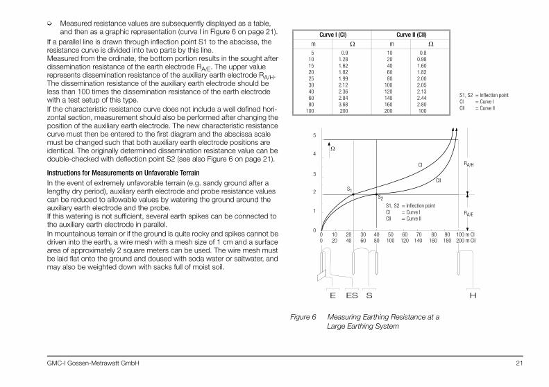
➭ Measured resistance values are subsequently displayed as a table, and then as a graphic representation (curve I in Figure 6 on page 21).
If a parallel line is drawn through inflection point S1 to the abscissa, the resistance curve is divided into two parts by this line.Measured from the ordinate, the bottom portion results in the sought after dissemination resistance of the earth electrode RA/E. The upper value represents dissemination resistance of the auxiliary earth electrode RA/H. The dissemination resistance of the auxiliary earth electrode should be less than 100 times the dissemination resistance of the earth electrode with a test setup of this type.If the characteristic resistance curve does not include a well defined hori-zontal section, measurement should also be performed after changing the position of the auxiliary earth electrode. The new characteristic resistance curve must then be entered to the first diagram and the abscissa scale must be changed such that both auxiliary earth electrode positions are identical. The originally determined dissemination resistance value can be double-checked with deflection point S2 (see also Figure 6 on page 21).
Instructions for Measurements on Unfavorable TerrainIn the event of extremely unfavorable terrain (e.g. sandy ground after a lengthy dry period), auxiliary earth electrode and probe resistance values can be reduced to allowable values by watering the ground around the auxiliary earth electrode and the probe. If this watering is not sufficient, several earth spikes can be connected to the auxiliary earth electrode in parallel.In mountainous terrain or if the ground is quite rocky and spikes cannot be driven into the earth, a wire mesh with a mesh size of 1 cm and a surface area of approximately 2 square meters can be used. The wire mesh must be laid flat onto the ground and doused with soda water or saltwater, and may also be weighted down with sacks full of moist soil.
Figure 6 Measuring Earthing Resistance at aLarge Earthing System
Curve I (CI) Curve II (CII)m Ω m Ω5
1015202530406080
100
0.91.281.621.821.992.122.362.843.68200
1020406080
100120140160200
0.80.981.601.822.002.052.132.442.80100
S1, S2 = Inflection pointCI = Curve ICII = Curve II
S1, S2 = Inflection pointCI = Curve ICII = Curve II
S1S2
CI
CII
Ω4
3
2
1
010 20 30 40 50 60 70 80 90 100 m CI20 40 60 80 100 120 140 160 180 200 m CII
5
RA/H
RA/E
00
S HESE
22 GMC-I Gossen-Metrawatt GmbH
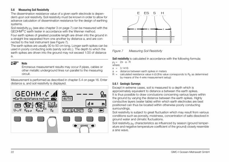
5.6 Measuring Soil ResistivityThe dissemination resistance value of a given earth electrode is depen-dent upon soil resistivity. Soil resistivity must be known in order to allow for advance calculation of dissemination resistance for the design of earthing systems.Soil resistivity ρE (see also chapter 3 on page 7) can be measured with the GEOHM®C earth tester in accordance with the Wenner method.Four earth spikes of greatest possible length are driven into the ground in a straight line separated from one another by distance a, and are con-nected to the test instrument (see Figure 7).The earth spikes are usually 30 to 50 cm long. Longer earth spikes can be used in poorly conducting soils (sandy soil etc.). The depth to which the earth spikes are driven into the ground may not exceed 1/20 of distance a.
NoteErroneous measurement results may occur if pipes, cables or other metallic underground lines run parallel to the measuring circuit.
Measurement is performed as described in chapter 5.4 on page 16. Enter distance a, and soil resistivity is displayed.
Figure 7 Measuring Soil Resistivity
Soil resistivity is calculated in accordance with the following formula:ρE = 2π ⋅ a ⋅ Rwhere:π = 3.1416a = distance between earth spikes in metersR = calculated resistance value in Ω (this value corresponds to RE as determined
by means of the 4-wire measurement setup)
5.6.1 Geologic SurveysExcept in extreme cases, soil is measured to a depth which is approximately equivalent to distance a between the earth spikes. It is thus possible to draw conclusions concerning various layers within the ground by varying the distance between the earth spikes. Highly conductive layers (water table) within which earth electrodes are best positioned can thus be located within otherwise poorly conducting surroundings.Soil resistivity is subject to great fluctuation which may result from various conditions such as porosity, moistness, concentration of salts dissolved in ground water and climatic fluctuations.Soil resistivity ρE characteristics as influenced by season (ground temper-ature and negative temperature coefficient of the ground) closely resemble a sine wave.
START
S HESE
aa a

GMC-I Gossen-Metrawatt GmbH 23
Figure 8 Soil resistivity ρE in as influenced by season without taking precipitation into consideration(earth spike depth < 1.5 m)
The following table shows typical soil resistivity for several types of soil.
Table 1 Soil Resistivity ρE for Various Types of Soil
5.6.2 Calculating Dissemination ResistanceThe following table includes formulas for calculating dissemination resistance for various types of earth electrodes. These rule-of-thumb formulas are entirely adequate for practical application.
Table 2 Formulas for the Calculation of Dissemination Resistance RA for Various Types of Earth Electrodes
RA= Dissemination resistance (Ω)ρE = Soil resistivity (Ωm)I = Earth electrode length (m)D = Ring earth electrode diameter, diameter of the equivalent circular area of a
mesh earth electrode or diameter of a hemispherical earth electrode (m)F = Surface area (square meters) enclosed by a ring or a mesh earth electrodea = Edge length (m) of a rectangular earth plate, a is defined as follows for rectan-
gular earth plates: √ b x c, where b and c are the two sides of the rectangle.J = Volume (cubic meters) of an individual foundation
Type of Soil Soil ResistivityρE [Ωm]
Wet bog soil 8 … 60
Arable fields, loam and clay, moist gravel 20 … 300
Moist, sandy soil 200 … 600
Dry sandy soil, dry gravel 200 … 2000
Rocky ground 300 … 8000
Bedrock 104 … 1010
+ρE (%)
10
20
30
-10
-20
-30
Jan. May Sept.March July Nov.
Number Earth Electrode Type Formula Auxiliary Information
1 Earth strip (crow’s foot earth electrode) —
2 Earth rod —
3 Ring earth electrode D = 1.13 ·
4 Mesh earth electrode D = 1.13 ·
5 Earth plate —
6 Hemispherical earth electrode D = 1.57 ·
RA
2 ρE⋅I
------------=
RA
ρE
I-----=
RA
2 ρE⋅3D------------= F2
RA
2 ρE⋅2D------------= F2
RA
2 ρE⋅
4,5 a⋅-------------=
RA
ρE
π D⋅----------= J3

24 GMC-I Gossen-Metrawatt GmbH
5.7 Measuring Ohmic ResistanceThe resistance of liquid and solid conductors can be measured with the GEOHM®C earth tester, as long as they are capacitance and induction-free.
5.7.1 2-Wire Connection➭ Connect the resistance to be measured RX between jacks E and H.
Figure 9 Measuring Ohmic Resistance with a 2-Wire Test Setup
NoteCable resistance can be measured with this test setup.
5.7.2 4-Wire Connection➭ Use 4-wire connection if cable resistance is not to be included in the
measurement results.
Figure 10 Measuring Ohmic Resistance with a 4-Wire Test Setup
S HESE
RX
START
RX
S HESE
START

GMC-I Gossen-Metrawatt GmbH 25
6 Database FunctionDisplayed measurement data can be saved individually for each measure-ment to the internal database either with or without a comment. In order to assign the individual measured values to various buildings, customers etc., a data record must first be created with its own memory address.
6.1 Creating a Data Record – Data Function➭ Press the data softkey.
➭ First, enter the desired memory address with the softkeys. After acknowledging this entry with the START key (press at center), the cursor appears at the first entry position (BUILDING).
No entry is required for the customer ID field, as long as measurements are only performed for a single company.The M-TYPE field (measurement type) is used to designate what kind of measurement is involved. This entry is required in order to generate a report with PS3 test instrument software for lightning protection systems.
M-TYPE Setting SignificanceD Continuity to metallic installations
DG Continuity to metallic gas lines
DW Continuity to metallic water lines
DL Continuity to metallic ventilation systems
D1, D2, D3, D4 Continuity to other, user-defined types of metallic systems
U Contact resistance measurement at all measuring points in order to determine continuity of all conductors. The number assigned to the measurement designates resistance between specific test joints, e.g. measurement number 1 indicates resistance between test joints 1 and 2, measurement 2 between test joints 2 and 3 etc.
E Measurement of earth dissemination resistance from individual earth electrodes with open test joints
! Measurement of earth dissemination resistance for the entire system with closed test joints

26 GMC-I Gossen-Metrawatt GmbH
➭ Entries can be made to the BUILDING, M-TYPE and CUSTOMER ID fields one after the other, and a building designation can be entered with the help of the softkeys.
Data Entry: The desired alphanumeric characters can be displayed with the help of the and keys, and then selected with the appropriate softkey. Control characters are entered in the same way and have the following functions: ←: Move cursor to the left (without deleting characters) →: Move cursor to the right (without deleting characters)↵: Same function as the START key
After a character has been selected, the cursor moves one place to the right. If the ↵ character is entered or the START key is pressed (press at center), the cursor moves to the next field. After the BUILDING, M-TYPE and CUSTOMER-ID fields have been completed and entries have been acknowledged with the ↵ command, they are highlighted at the display. After acknowledging once more with the ↵ character, a designation for the currently selected building can be entered.
NoteThis information is required by the PC software in order to enter measured values to the database, as well as for automatic generation of reports.
6.2 Saving Measured Values to Memory – STORE Function➭ Start the desired measurement. The STORE softkey is displayed after
the measurement instead of the INFO key. The STORE key is not displayed until after a given amount of time has elapsed for measurements which are performed without the START key, so that the operator can first query the help text with the INFO key.
➭ The displayed measurement values are stored to the currently selected database memory address by briefly acknowledging with the STORE key. The key is briefly displayed as an inverse image during storage to memory.
➭ Pressing and holding the STORE key allows for the entry of a comment, and storage of the current measurement. Entering a Comment: Display the desired alphanumeric character with the or the key and select the desired character with the corresponding softkey. Control characters are displayed in the same way and have the following functions: ←: Backspace and delete ↵: Same function as the START key After each character has been selected, the cursor moves one place to the right. Already entered characters can be deleted in reverse by pressing and holding any softkey (except for ↵). After entry of up to 15 characters, save the measurement values and the comment by acknowledging with the START key (press at center) . The following message appears: “Saving data”.
START

GMC-I Gossen-Metrawatt GmbH 27
6.3 Querying Data Records – View Function➭ Press the View key.➭ You can scroll forward through the memory addresses with the
key, or backwards with the key.➭ After the memory address has been opened, the individual data
records which have been stored to memory along with consecutive numbers can be queried with the Prev. and Next softkeys.
If you discover that a measurement value for the currently selected earthing system is missing, the required measurement can be performed immediately.
6.3.1 Deleting a Data Record from within a Memory Address – View Function➭ Press the Del key. No security requests appear.
Data record numbering is changed as soon as an individual data record is deleted.
6.3.2 Deleting a Memory Address – Data Function➭ Press the Data key.➭ Enter blanks to the data fields BUIDLING, M-TYPE and CUSTOMER ID. After
these fields have been entirely overwritten with blanks, they are dis-played as inverse images.
➭ Acknowledge with the START key (press at center). All data from the selected memory address are deleted.
START
START
28 GMC-I Gossen-Metrawatt GmbH
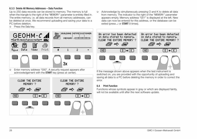
6.3.3 Delete All Memory Addresses – Data FunctionUp to 250 data records can be stored to memory. The memory is full when the triangle to the right of the “MEMORY:” parameter is entirely filled in. The entire memory, i.e. all data records from all memory addresses, can be deleted at once. We recommend uploading and saving your data to a PC before deletion.➭ Press the Data key.
➭ Enter memory address “000”. A security request appears after acknowledgement with the START key (press at center).
➭ Acknowledge by simultaneously pressing O and K to delete all data from memory. The indicator to the right of the “MEMORY:” parameter appears empty. Memory address “001” is displayed at the left. New data can now be entered for this address, or the database can be exited (press ↵ or START 9 times).
If the message shown above appears when the test instrument is switched on, you are provided with the opportunity of uploading and saving all data to a PC before deleting the memory in order to correct the error.
6.4 Print FunctionFunctions whose symbols appear in gray or which are displayed faintly, will not be available until after the next software update.
3x
+
+

GMC-I Gossen-Metrawatt GmbH 29
7 Characteristic Values
1) Manual measuring range selection only, for resistance measurements see chapter 5.72) as from software version AD3) For sinusoidal measured quantities only
Output Voltage max. 50 VTRMS at 128 Hz ±0.5 Hz
Reference ConditionsAmbient Temperature 23 °C ±2 KRelative Humidity 40% … 60%Battery Voltage 5.5 V ±1%Line Frequency 50 Hz ±0.2 HzLine Voltage Waveshape sine (deviation between effective and rectified
value < 1%)
Nominal Conditions of UseSeries Mode Interference Voltage < 3 V AC DCAdditional Error due to Probe andAux. Earth Electrode Resistance < 5% pf (RE+RH+RS)Max. Probe Resistance < 70 kΩMax. Auxiliary EarthElectrode Resistance < 50 kΩMax. Earth and AuxiliaryEarth Electrode Resistance ≤ 50 kΩ, see graph RE as a function of RH
Ambient ConditionsNominal Range of Use 0 °C … +40 °COperating Temperature –10 °C … +50 °CStorage Temperature –20 °C … +60 °C (without batteries)Relative Humidity max. 75%, no condensation allowedElevation to 2000 m
Power SupplyBatteries 4 ea. 1.5 V baby cell (4 x C-size)
(alkaline manganese per IEC LR14)Battery Voltage 4.6 … 6.5 VBattery Service Life 30 hours or 1000 measurements at RE
(with 10 s on-time and automatic device shutdown after each measurement, without display illumination)
Rechargeable Batteries NiCd or NiMHBattery Charger NA 0100S (article no. Z501D),(not included) 3.5 mm jack plugCharging Voltage / Time 9 V / approx. 14 hoursDue to their reduced charging capacity, fewer measurements can be per-formed with rechargeable batteries than with normal batteries as a rule.
Meas. Qty. Display range Measuring Range Impedance,
Test Current Intrinsic Error Measuring Error
RE
0.01 ... 20 Ω0.1 ... 200 Ω1 Ω ... 2 kΩ
10 Ω ... 20 kΩ10 Ω ... 50 kΩ
1.0 ... 20 Ω5 ... 200 Ω
50 Ω ... 2 kΩ500 Ω ... 20 kΩ
500 Ω ... 50 kΩ 1)
10 mA1 mA
100 µA100 µA100 µA
±(3%rdg.+6d)
±(10% rdg. + 6d)±(10% rdg. + 6d)±(10% rdg. + 6d)±(10% rdg. + 6d)±(16% rdg. + 10d)
U 2) 1.0 ... 99.9 V100 ... 250 V
10 ... 250 V 500 kΩ ±(2%rdg.+2d) ±(4% rdg. + 3d)U~ 3) 0 ... 99.9 V
100 ... 300 V
f 3) 15 ... 99.9 Hz100 ... 400 Hz 45 ... 200 Hz 500 kΩ ±(0.1%rdg.+1d) ±(0.2% rdg. + 1d) 0.5
25
50
0.5 25 50 RH [kΩ]
RE
[kΩ
]
30 GMC-I Gossen-Metrawatt GmbH
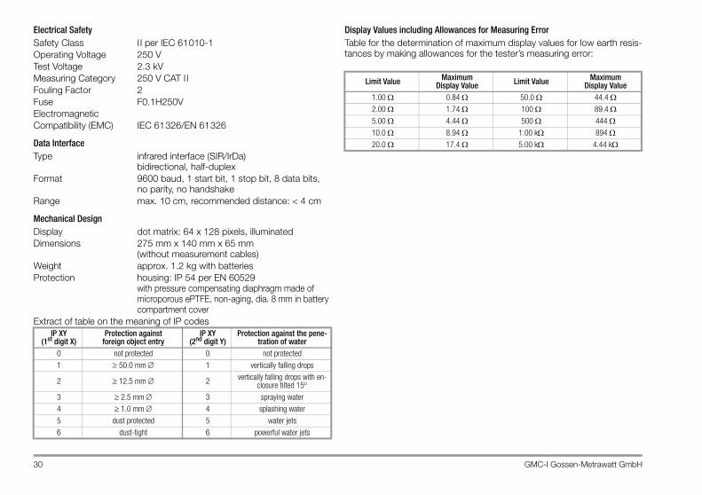
Electrical SafetySafety Class II per IEC 61010-1Operating Voltage 250 VTest Voltage 2.3 kVMeasuring Category 250 V CAT I IFouling Factor 2Fuse F0.1H250VElectromagneticCompatibility (EMC) IEC 61326/EN 61326
Data InterfaceType infrared interface (SIR/IrDa)
bidirectional, half-duplexFormat 9600 baud, 1 start bit, 1 stop bit, 8 data bits,
no parity, no handshakeRange max. 10 cm, recommended distance: < 4 cm
Mechanical DesignDisplay dot matrix: 64 x 128 pixels, illuminatedDimensions 275 mm x 140 mm x 65 mm
(without measurement cables)Weight approx. 1.2 kg with batteriesProtection housing: IP 54 per EN 60529
with pressure compensating diaphragm made of microporous ePTFE, non-aging, dia. 8 mm in battery compartment cover
Extract of table on the meaning of IP codes
Display Values including Allowances for Measuring ErrorTable for the determination of maximum display values for low earth resis-tances by making allowances for the tester’s measuring error:
IP XY (1st digit X)
Protection againstforeign object entry
IP XY (2nd digit Y)
Protection against the pene-tration of water
0 not protected 0 not protected
1 ≥ 50.0 mm ∅ 1 vertically falling drops
2 ≥ 12.5 mm ∅ 2 vertically falling drops with en-closure tilted 15°
3 ≥ 2.5 mm ∅ 3 spraying water
4 ≥ 1.0 mm ∅ 4 splashing water
5 dust protected 5 water jets
6 dust-tight 6 powerful water jets
Limit Value MaximumDisplay Value Limit Value Maximum
Display Value1.00 Ω 0.84 Ω 50.0 Ω 44.4 Ω2.00 Ω 1.74 Ω 100 Ω 89.4 Ω5.00 Ω 4.44 Ω 500 Ω 444 Ω10.0 Ω 8.94 Ω 1.00 kΩ 894 Ω20.0 Ω 17.4 Ω 5.00 kΩ 4.44 kΩ
GMC-I Gossen-Metrawatt GmbH 31
8 Maintenance
8.1 HousingNo special maintenance is required for the housing. Keep outside surfaces clean. Use a slightly dampened cloth and/or a special purifier for synthetic material for cleaning. Avoid the use of cleansers, abrasives and solvents.
Attention!!For the following reasons, the housing may not be opened by the operator: – Unexpected problems may occur during reassembly.– Sealing requirements are no longer fulfilled.
Device Return and Environmentally Compatible DisposalThe instrument is a category 9 product (monitoring and control instru-ment) in accordance with ElektroG (German Electrical and Electronic Device Law). This device is not subject to the RoHS directive.We identify our electrical and electronic devices (as of August 2005) in accordance with WEEE 2002/96/EG and ElektroG with the symbol shown to the right per DIN EN 50419 .These devices may not be disposed with the trash. Please con-tact our service department regarding the return of old devices.
8.2 Battery OperationWhen only one solid segment remains in the battery symbol, the batteries must be replaced, or recharged if rechargeable batteries are used.
Attention!!Before opening, the instrument must be completely disconnected from all external electrical circuits!
Check the batteries at short, regular intervals or after lengthy periods of storage to make sure no leakage has occurred. If leakage has occurred, the electrolyte must be carefully and completely removed from the instru-ment with a damp cloth before new batteries are installed.
Charging the Batteries
Attention!!Use only the Z501D battery charger with safe electrical isolation and a nominal secondary voltage of 9 V DC to recharge the bat-teries. Before connecting the battery charger to the charging socket at the instrument, make sure of the following points:– Rechargeable batteries have been installed (not normal batteries).– The instrument has been disconnected from the measuring
circuit at all poles.– The voltage selector at the charger has been set to 9 V.
Connect the Z501D battery charger to the charging socket with the 3.5 mm jack plug. Set the voltage selector switch at the Z501D to 9 V. Switch the test instrument on. The test instrument recognizes the fact that a battery charger has been connected and starts the charging cycle. The 5 segments of the battery symbol are continuously displayed in a sweep-ing pattern from left to right for the entire duration of the charging cycle.Depleted batteries require a charging cycle of approximately 14 hours. If the batteries are exhausted to a great enough extent, the test instrument can no longer be switched on. If this is the case, leave the test instrument connected to the activated battery charger for about 30 minutes, and then proceed as described above.
32 GMC-I Gossen-Metrawatt GmbH
Storing the Rechargeable Battery Pack1 year at –20 … +35 °C3 months at –20 … +45 °C1 month at –20 … +55 °C
Replacing the Rechargeable Battery Pack➭ Loosen the two slotted screws at the battery compartment cover on
the housing rear panel and remove the cover.➭ Insert the rechargeable battery pack making certain it is poled in
accordance with the symbols.➭ Replace the cover and retighten the screws.
Attention!!The instrument may not be operated if the battery compartment cover has not been installed and properly tightened!
Battery DisposalDispose of depleted batteries in an environmentally sound fashion, i.e. bring them to an official collection center.
8.3 FusesIf the fuse has blown due to an overload, an appropriate error message appears at the LCD (RH > max). However, the instrument’s voltage measuring range is still functional.
Replacing the FuseThe fuse can be accessed easily from the outside of the instrument, and is located to the left of the charging socket.➭ Remove the threaded fuse cap with the help of a suitable tool (e.g. a
screwdriver) by pressing and turning counterclockwise.
Attention!!Incorrect fuses may cause severe damage to the test instrument. Only original fuses from GMC-I Gossen-Metrawatt GmbH assure the required protection by means of suitable breaking character-istics (article no. 3-578-235-01). Bridging or repairing fuses is prohibited! The instrument may be damaged if fuses with other current ratings, blowing or breaking characteristics are used!
➭ Remove the defective fuse and replace it with a new replacement fuse. Replacement fuses are located in the battery compartment.
➭ Insert the new fuse and the cap together, and lock into place by turning clockwise.
➭ Replace the battery compartment cover and secure with the screws.

GMC-I Gossen-Metrawatt GmbH 33
9 Repair and Replacement Parts Service,DKD Calibration Lab* and Rental Instrument Service
If required please contact:
GMC-I Gossen-Metrawatt GmbHService Center Thomas-Mann-Str. 2090471 Nürnberg, GermanyPhone: +49 911 86 02 - 0Fax +49 911 86 02 - 2 53E-mail: [email protected]
This address is only valid in Germany.Please contact our representatives or subsidiaries for service in other countries.
* Calibration Laboratory for Electrical Quantities DKD–K–19701accredited per DIN EN ISO/IEC 17025
Accredited measured quantities: direct voltage, direct current values, DC resistance, alternating voltage, alternating current values, AC active power, AC apparent power, DC power, capacitance and frequency
Competent PartnerGMC-I Gossen-Metrawatt GmbH is certified in accordance with DIN EN ISO 9001:2000.Our DKD calibration laboratory is accredited by the Physikalisch Tech-nische Bundesanstalt (German Federal Institute of Physics and Metrology) and the Deutscher Kalibrierdienst (German Calibration Service) in accor-dance with DIN EN ISO/IEC 17025 by under registration number DKD–K–19701.We offer a complete range of expertise in the field of metrology: from test reports and proprietary calibration certificates right on up to DKD calibration certificates.Our spectrum of offerings is rounded out with free test equipment manage-ment.An on-site DKD calibration station is an integral part of our service depart-ment. If errors are discovered during calibration, our specialized personnel are capable of completing repairs using original replacement parts.As a full service calibration laboratory, we can calibrate instruments from other manufacturers as well.
10 Product SupportIf required please contact:
GMC-I Gossen-Metrawatt GmbHProduct Support Hotline Phone: +49 911 86 02 - 112Fax +49 911 86 02 - 709E-Mail [email protected]

34 GMC-I Gossen-Metrawatt GmbH
GMC-I Gossen-Metrawatt GmbH 35
Edited in Germany • Subject to change without notice • A pdf version is available on the internet.
GMC-I Gossen-Metrawatt GmbHThomas-Mann-Str. 16-2090471 Nürnberg • Germany
Phone +49-(0)-911-8602-0Fax +49-(0)-911-8602-669E-Mail [email protected]