GeoGebra Training Material -...
60
VccSSe Virtual Community Collaborating Space for Science Education “Virtual Instrumentation in Science Education” Training Material: Introduction to GeoGebra 1/60 Training material Introduction to GeoGebra Content: A. Introduction B. First steps with GeoGebra C. Introduction drill D. Export E. Represent and drag objects F. Algebra window G. Some proposed exercises H. Functions I I. Functions II J. How to insert the random function in a GeoGebra applet K. References A. Introduction The goal of this document is to facilitate the teaching staff the suitable knowledge which will enable them to handle and/or modify the proposed exercises and to adapt them to their didactic necessities. In general, an exercise or activity aimed at to the pupils of a specific level is taken as the starting point to know some of the possibilities that the GeoGebra software offers. Among other facilities, it allows to generate html files from GeoGebra documents. This free software application, General GNU Public License, has been developed by Markus Hohenwarter, from the University of Salzburg (Austria). It combines the benefits of the dynamic geometry software with those of the algebraic calculation systems. The GeoGebra objects are dynamically considered under these two aspects -graphical representation and analytical definition. The last stable version -GeoGebra 3.RC1 (Release Candidate- can be downloaded from the Website of this software: http://www.geogebra.org and, whenever possible, the WebStar versions in the already mentioned website (WebStar ) can be used to ensure the usage of the last stable release. It should be clarified that we are not dealing with a course on GeoGebra, so we will not exhaust the possibilities of this software. We will try to focus on those aspects that allow us to modify and/or to generate exercises similar to the ones displayed. Users will have at their disposal a Help file (in pdf and html formats), after installing the program,. Besides, a Quick Reference Guide and Help can be downloaded from the Website (Help ). In this very section there are other three GeoGebra documents: GeoGebra Applet parameter GeoGebra Applets and JavaScript GeoGebra XML file format that can be very useful for all those interested in knowing the features of the GeoGebra files and their possible ways to use. We will dedicate some chapters to explain how this
Transcript of GeoGebra Training Material -...

VccSSe
Virtual Community Collaborating Space for Science Education
“Virtual Instrumentat ion in Science Education”
Training Material: Introduction to GeoGebra 1/60
Training material
Introduction to GeoGebra
Content: A. Introduction B. First steps with GeoGebra C. Introduction drill D. Export E. Represent and drag objects F. Algebra window G. Some proposed exercises H. Functions I I. Functions II J. How to insert the random function in a GeoGebra applet K. References
A. Introduction
The goal of this document is to facilitate the teaching staff the suitable knowledge which will enable them to handle and/or modify the proposed exercises and to adapt them to their didactic necessities.
In general, an exercise or activity aimed at to the pupils of a specific level is taken as the starting point to know some of the possibilities that the GeoGebra software offers. Among other facilities, it allows to generate html files from GeoGebra documents.
This free software application, General GNU Public License, has been developed by Markus Hohenwarter, from the University of Salzburg (Austria). It combines the benefits of the dynamic geometry software with those of the algebraic calculation systems. The GeoGebra objects are dynamically considered under these two aspects -graphical representation and analytical definition.
The last stable version -GeoGebra 3.RC1 (Release Candidate- can be downloaded from the Website of this software:
http://www.geogebra.organd, whenever possible, the WebStar versions in the already mentioned website (WebStar) can be used to ensure the usage of the last stable release.
It should be clarified that we are not dealing with a course on GeoGebra, so we will not exhaust the possibilities of this software. We will try to focus on those aspects that allow us to modify and/or to generate exercises similar to the ones displayed.
Users will have at their disposal a Help file (in pdf and html formats), after installing the program,. Besides, a Quick Reference Guide and Help can be downloaded from the Website (Help). In this very section there are other three GeoGebra documents:
GeoGebra Applet parameterGeoGebra Applets and JavaScript
GeoGebra XML file formatthat can be very useful for all those interested in knowing the features of the GeoGebra files and their possible ways to use. We will dedicate some chapters to explain how this

VccSSe
Virtual Community Collaborating Space for Science Education
“Virtual Instrumentat ion in Science Education”
application works in a general way and also to the generation of interactive exercises in html format.
We suggest create 3 folders: activities, solutions and work and unzipping:
all the files of the file activities.zip in the folder activities.
all the files of the file solutions.zip in the folder solutions.
The folder work will contains the proposed activities. A1. Icons used
We will use the following icons:
Makes reference to an existing external link which requires an Internet connection
Opens a file in the folder activities
Saves (or Opens) a file in the folder work
One file in the folder solutions
A2. Configurations and programs
To enhance GeoGebra work the virtual Java machine is required. If you don’t have any installed you can download it here:
Sun Microsystems. Virtual Java machine corresponding to Java Runtime Environment Version 6.0 Update 5.
The eventual modification of the html files generated by GeoGebra can be made by using any web page editor. For these modifications we will use Microsoft FrontPage 2003 though any page editor could do. We will assume that the user knows how to use this program, at least, at a basic level (open, save, edit…).
B. First steps with GeoGebra
B1. Document window
To start the GeoGebra application double click on the corresponding icon in the desk
Or follow the path: Start All Programs Geogebra Geogebra.
Training Material: Introduction to GeoGebra 2/60

VccSSe
Virtual Community Collaborating Space for Science Education
“Virtual Instrumentat ion in Science Education”
Figure 1 – Start GeoGebra
You can do it either ways to get to the application window where the basic elements have been remarked: Toolbar, Input field, Algebra window and Drawing pad.
Figure 2 – The basic elements of the GeoGebra application
To Hide/show the axes, select the command Axes from the View menu. By selecting one of the modes in the tool bar you can do constructions on the drawing
pad. Coordinates or equations of the objects appear in the algebra window. In the input field you can write coordinates, equations, commands and functions that
are displayed at the drawing pad after pressing the Enter key (or equivalent).
Training Material: Introduction to GeoGebra 3/60

VccSSe
Virtual Community Collaborating Space for Science Education
“Virtual Instrumentat ion in Science Education”
B2. Representation of points
Click on New Point button. Place the cursor on the drawing pad and left click. Point A is
displayed as represented here:
Figure 3 – Representation of points
The last selected mode remains active until another one is selected, that is to say, if we scroll the mouse and left click again a new point will be created. The two arrows on the top right area (tool bar) allow us to undo or redo the last actions.
B3. Change name
GeoGebra assigns names to the objects alphabetically. In the case of the points: A, B, C…
To change the name of an object:
Training Material: Introduction to GeoGebra 4/60

VccSSe
Virtual Community Collaborating Space for Science Education
“Virtual Instrumentat ion in Science Education”
Click on Move button.
Place the cursor on the object and right click. In the context menu select
Rename
In the Rename window, type the new name of the object and press the key.
In this case we have changed the point A to Andrés. B4. Modify properties
As it can be seen in the previous picture, after right clicking on an object, the context menu with several commands is displayed. The last one, Properties … allows access to all the properties of an object.
Figure 4 – Modify properties
Training Material: Introduction to GeoGebra 5/60

VccSSe
Virtual Community Collaborating Space for Science Education
“Virtual Instrumentat ion in Science Education”
Let’s change the colour and the size of that point. To change the colour, click on the tab and choose a new one by clicking on
the suitable cell. To finish, click on the button .
Figure 5 – Change the colour
To change the size of the point, click on the tab and move the slider until the measure you want. To finish, click on the button .
Figure 6 – Change the size of the point
After the described modifications, the appearance of the point renamed as Andrés is presented this way:
Training Material: Introduction to GeoGebra 6/60

VccSSe
Virtual Community Collaborating Space for Science Education
“Virtual Instrumentat ion in Science Education”
Figure 7 – The appearance of the point Andrés
C. Introduction drill
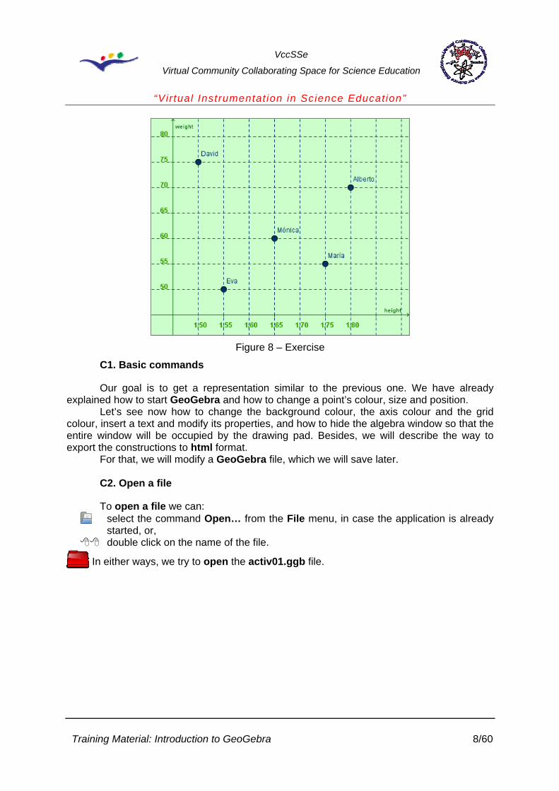
The image shows a height (in meters) - weight (in kilograms) graph corresponding to a group of 5 friends as it can be seen in the records made due to a check-up (notice the lack of reference to the interruption of the axes).
Look at the chart from the Figure 7 and answer the following questions: - How tall is Alberto? - Which is Mónica’s weight? - Who is the shortest person? And the tallest? - Who is the most obese person? And the thinnest? - How tall is David and which is his weight? - What happens if we join the points? - Do you find the axis scale appropriate?
Training Material: Introduction to GeoGebra 7/60
VccSSe
Virtual Community Collaborating Space for Science Education
“Virtual Instrumentat ion in Science Education”
Figure 8 – Exercise
C1. Basic commands
Our goal is to get a representation similar to the previous one. We have already explained how to start GeoGebra and how to change a point’s colour, size and position.
Let’s see now how to change the background colour, the axis colour and the grid colour, insert a text and modify its properties, and how to hide the algebra window so that the entire window will be occupied by the drawing pad. Besides, we will describe the way to export the constructions to html format.
For that, we will modify a GeoGebra file, which we will save later. C2. Open a file
To open a file we can: select the command Open… from the File menu, in case the application is already
started, or, double click on the name of the file.
In either ways, we try to open the activ01.ggb file.
Training Material: Introduction to GeoGebra 8/60

VccSSe
Virtual Community Collaborating Space for Science Education
“Virtual Instrumentat ion in Science Education”
Figure 9 – Open a file
Figure 10 – A GeoGebra file
If the grid is not visualized, select the command Grid from the View menu.
Training Material: Introduction to GeoGebra 9/60

VccSSe
Virtual Community Collaborating Space for Science Education
“Virtual Instrumentat ion in Science Education”
C3. Hide elements
Let’s hide the elements that, in this moment, are not going to be used (algebra window and edit line or input field).
To close the algebra window: Select the command Algebra window from the View menu.
To hide the input line select the command Input field from the View menu. The ticks shown in the image, in these items, must disappear.
Figure 11 – The View menu
C4. Background colour
To change the background colour: select Drawing Pad… from the Options menu or, place the cursor on any free area (from the drawing pad), right click and choose
Properties.
Training Material: Introduction to GeoGebra 10/60

VccSSe
Virtual Community Collaborating Space for Science Education
“Virtual Instrumentat ion in Science Education”
Training Material: Introduction to GeoGebra 11/60
aa)) bb))
Figure 12 – a) Options menu and b) context menu
In the Drawing Pad window, click on the Background colour button and proceed as in the case of the points (First steps).
Figure 13 – The Drawing Pad window
VccSSe
Virtual Community Collaborating Space for Science Education
“Virtual Instrumentat ion in Science Education”
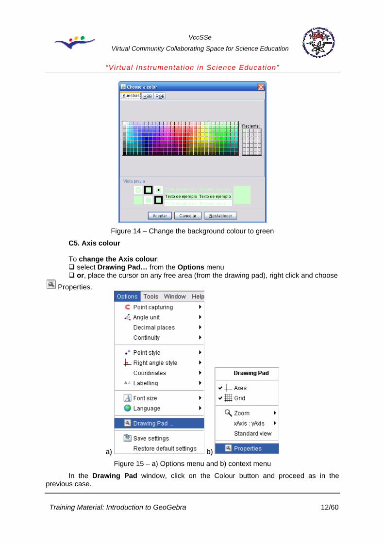
Figure 14 – Change the background colour to green
C5. Axis colour
To change the Axis colour: select Drawing Pad… from the Options menu or, place the cursor on any free area (from the drawing pad), right click and choose
Properties.
a
Training Material: Introduction to GeoGebra 12/60
a)) bb))
Figure 15 – a) Options menu and b) context menu
In the Drawing Pad window, click on the Colour button and proceed as in the previous case.

VccSSe
Virtual Community Collaborating Space for Science Education
“Virtual Instrumentat ion in Science Education”
Figure 16 – The Drawing Pad window. The Axes tab
Figure 17 – Change the axis colour to green.
C6. Grid colour
To change the grid colour proceed as in the previous cases until visualising the Drawing Pad window.
Click on the tab, and then on the Colour button and proceed as in any of the previous cases.
Change the grey colour to dark blue.
Training Material: Introduction to GeoGebra 13/60
VccSSe
Virtual Community Collaborating Space for Science Education
“Virtual Instrumentat ion in Science Education”
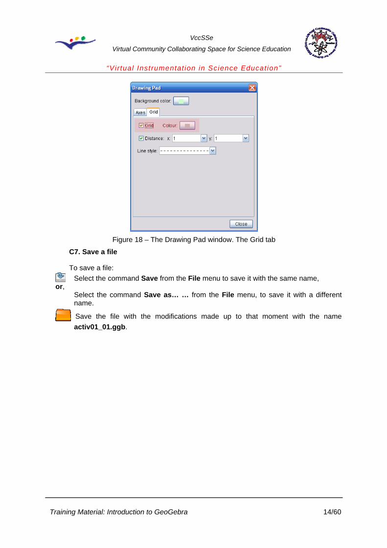
Figure 18 – The Drawing Pad window. The Grid tab
C7. Save a file
To save a file: Select the command Save from the File menu to save it with the same name,
or, Select the command Save as… … from the File menu, to save it with a different
name.
Save the file with the modifications made up to that moment with the name activ01_01.ggb.
Training Material: Introduction to GeoGebra 14/60
VccSSe
Virtual Community Collaborating Space for Science Education
“Virtual Instrumentat ion in Science Education”
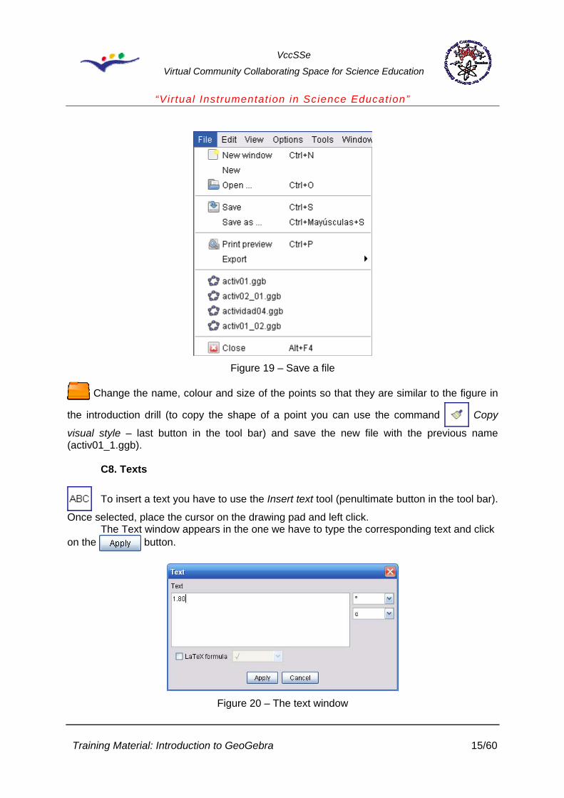
Figure 19 – Save a file
Change the name, colour and size of the points so that they are similar to the figure in
the introduction drill (to copy the shape of a point you can use the command Copy
visual style – last button in the tool bar) and save the new file with the previous name (activ01_1.ggb).
C8. Texts
To insert a text you have to use the Insert text tool (penultimate button in the tool bar).
Once selected, place the cursor on the drawing pad and left click. The Text window appears in the one we have to type the corresponding text and click
on the button.
Figure 20 – The text window
Training Material: Introduction to GeoGebra 15/60

VccSSe
Virtual Community Collaborating Space for Science Education
“Virtual Instrumentat ion in Science Education”
To complete the introduction drill we still need the texts 1.80 in the X axis and 80 in the Y axis. We type the texts (place the cursor, nearly at the same height that the already existing ones) and then, we modify its properties so that the style will be similar to that of the original figure.
We can use the Copy visual style tool, above mentioned, to copy some of the features in the existing texts. Once this operation is made, we place the cursor on the text, right click and in the context menu (Text T13) we choose Properties.
Figure 21 – The Properties window
In the Properties window, we select tab and we deactivate the Absolute position on screen cell.
In the Starting point field we write the coordinates of the text, (6.8, -0.5) and click on the button.
We repeat this operation with the Y axis. The coordinates in this case will be (-0.5, 7).
Save the new file with the name activ01_2.ggb.
D. Export
GeoGebra allows to export the constructions (the drawing pad or just a part of it) as graphics formats (png, eps, svg, emf), copy them in the Windows clipboard and turn them into an interactive html page.
Open the last saved activ01_2.ggb file in the previous session, or
the solution file activ01_2Sol.ggb.
Training Material: Introduction to GeoGebra 16/60

VccSSe
Virtual Community Collaborating Space for Science Education
“Virtual Instrumentat ion in Science Education”
It must look like the following figure:
Figure 22 – The activ01_2Sol.ggb file
The export menu is activated by the command Export from the File menu.
Figure 23 – Export a file in GeoGebra
By selecting the Drawing Pad as Picture (png, eps) … option, the drawing pad is copied in a chosen file.
The Export: Drawing Pad window allows to choose the format from the output file (png, eps, svg, emf), the scale and the resolution (only in the case of png format).
Training Material: Introduction to GeoGebra 17/60

VccSSe
Virtual Community Collaborating Space for Science Education
“Virtual Instrumentat ion in Science Education”
Figure 24 - Export: Drawing Pad window
By clicking on the button we get to the Save window, where we can choose the name and placement for the output file.
Figure 25 – The Save window
Training Material: Introduction to GeoGebra 18/60

VccSSe
Virtual Community Collaborating Space for Science Education
“Virtual Instrumentat ion in Science Education”
The Dynamic Worksheet as Webpage (html) … option allows to generate an html file which contains the construction and, at the same time, the movement of the free objects. It is possible to activate the application through a button and to allow the execution of the full program by double clicking on it.
In the window Export: Dynamic Worksheet (html) we can write the title, author and date on the corresponding fields which will appear as head and footnote of the html file. It is also possible to include a text above (Text above the construction) and after (Text after the construction) in the application window and to include html code in them.
a)
Training Material: Introduction to GeoGebra 19/60

VccSSe
Virtual Community Collaborating Space for Science Education
“Virtual Instrumentat ion in Science Education”
b) Figure 26 – The Export: Dynamic Worksheet (html) window. a) Advanced tab, b) General tab
The radio button Button to open application window with construction allows to hide the visualization of the construction until this button is pressed.
The tab allows to choose among the program options available for the user.
If the Double click opens application window cell is activated, the double click on the construction in the Web page generated allows to open GeoGebra with the same features that the Windows application.
In any case, several files are generated. If the name of the file is activ01_03.html, the files activ01_03.ggb, geogebra.jar, geogebra_cas.jar, geogebra_export.jar, geogebra_gui.jar, geogebra_properties.jar. are kept in the same folder.
Next, two images are presented as a result of the exportation of each of the options
found in the tab:
Training Material: Introduction to GeoGebra 20/60

VccSSe
Virtual Community Collaborating Space for Science Education
“Virtual Instrumentat ion in Science Education”
Figure 27 – Exportation result
Figure 28 – Exportation result
Training Material: Introduction to GeoGebra 21/60

VccSSe
Virtual Community Collaborating Space for Science Education
“Virtual Instrumentat ion in Science Education”
E. Represent and drag objects
E1. Representation of the points
1. In the following figure you can see the representation of the point P (3, 2). Remember that the first number, the abscise or x-coordinate, is represented on the horizontal axis (abscises); to the right of its origin if it is positive and to the left if negative. However, the ordinate or y-coordinate, the second number, is represented on the vertical axis (ordinates); above its origin if positive and below if negative.
Figure 29 – Example
If you drag the point P with the mouse you can see how the coordinates change. You can check that if the point is in the first or fourth quadrants, the x-coordinate (abscise) is positive, but if it is found in the third or in the second, the x-coordinate is negative. As regards the y-coordinate (ordinate), it is positive for the quadrants first and second and negative when the points are in the third or fourth quadrants.
2. The following figure has 4 points: two in the first quadrant, B and D, and two in the
second, A and C. The thing is to drag the points in such a way that there is one per quadrant regarding the attached table:
Point Quadrant
A 1
B 2
Training Material: Introduction to GeoGebra 22/60

VccSSe
Virtual Community Collaborating Space for Science Education
“Virtual Instrumentat ion in Science Education”
C 3
D 4
Figure 30 – Example
Complete now the following table:
Point Sign of x Sign of y
A
B
C
D
E2. Dragging objects, segments, texts
Let’s see how to make drills as the ones described in the previous paragraphs. We already know how to represent points and to change their names. Let’s see now how to limit their movement. We will explain later the way to define segments and to add texts with properties dealing with the existing objects.
Training Material: Introduction to GeoGebra 23/60

VccSSe
Virtual Community Collaborating Space for Science Education
“Virtual Instrumentat ion in Science Education”
E3. Restraint the dragging to the grid
We open the activ02.ggb file, which already has the labelled axis and it is placed in the centre of the window. The thing is to incorporate a point P, which can be dragged with the mouse and whose coordinates are to be shown together with the name, to present the corresponding segments to the abscise and ordinate values (see figure in Representation of the points, drill 1). Besides, we want this dragging limited to the points of the quadrant.
Let’s remember the way to define a point: Choose New Point, drag the cursor to the estimate position (3, 2) and left click. Change the name, size and colour until it looks like the original figure in this activity (see First steps).
To limit the dragging of the points to the grid we have to select the command Point capturing from the Options menu and choose on. If we drag now the point P we’ll see that when it is close to any of the points on the grid it is attracted by it. If we want it to jump from one point on the grid to another without allowing any mid-positions, we have to select on (Grid).
Figure 31 – Selecting On the grid
We can deal now with the distance between the units of the X and Y axis together with the ones defined for the grid. The definition of these distances is made in the Properties window in the Drawing Pad (see First steps).
The distance between the X and Y axis is set by default at 2 units and the distance between the points on the grid at 1 for both axis. If we want the points on the grid to be correspondent with 0.5 unit intervals, we will have to write that value in the unit field in the
tab. Let’s see these considerations with two figures. The one on the left shows the window
without the grid, whereas the one on the right with the 0.5 distance grid. If we have the on option (Grid) selected, the point P will change its coordinates in 0.5 unit intervals in both axis.
Training Material: Introduction to GeoGebra 24/60

VccSSe
Virtual Community Collaborating Space for Science Education
“Virtual Instrumentat ion in Science Education”
Figure 32 – Example
E4. Show the coordinates of one point
If in the Properties window of the point P, in the field Show label (in the tab), we select Name & Value, the P label adopts the shape we can see next in the image.
Figure 33 – Show the coordinate of one point
Another possibility is to hide the label (deactivate the Show label cell) and insert a text in the position of the point. That way we can get texts different in colour and printing to those in the point.
Training Material: Introduction to GeoGebra 25/60

VccSSe
Virtual Community Collaborating Space for Science Education
“Virtual Instrumentat ion in Science Education”
We define a text (see First steps) writing “P “ + P. What it is under quotation appears as it is; GeoGebra substitutes the P that follows + for the value of the point (in this case its
coordinates). Then, in the Properties window click on T1 (in the list of objects), tab, and
select bold ( ).
Figure 34 – Define a text
Figure 35 – The Properties window
In the tab choose a green shade and, finally, in the tab deactivate the Absolute position on screen cell.
Training Material: Introduction to GeoGebra 26/60

VccSSe
Virtual Community Collaborating Space for Science Education
“Virtual Instrumentat ion in Science Education”
Figure 36 – The Properties window. The Position tab
E5. Coordinates of a point
In the last figure it can be seen, in the Starting point field, a chunk of the original expression:
(x(P)) + 0.25, y(P) + 0.25) x(P) is the value of the x-coordinate of the P point and y(P) corresponds to the value
of the y-coordinate. These are dynamic values, that is to say, the values change regarding the position of the P point.
Save the file as activ02_01.ggb..
E6. Segments
The only thing left is to lay out the segments corresponding to the coordinates of the P point and put the appropriate labels.
We choose the Segment between two points tool (third button to the left in the tool bar). We draw the segment between P and the X axis, corresponding to the ordinate. In order to get this segment to always show the value of the ordinate, we have to modify its properties
(right click on the segment and choose ) and assign the point (x(P), 0) as its end. Next, we can delete the point A drawn by the program to lay the segment out.
Training Material: Introduction to GeoGebra 27/60

VccSSe
Virtual Community Collaborating Space for Science Education
“Virtual Instrumentat ion in Science Education”
Figure 37 – The Properties window
And the same way to draw the segment corresponding to the y-cooordinate. In this case the ends will be P and (0, y(P)).
In a similar way to the insertion of texts in the case of the point P, we can insert the labels of the segments (to show xP you have to write x_P).
E7. Text with parameters
With the cursor surrounding the segment a, we choose the Insert text tool (penultimate button in the tool bar) and we write
“y_P = “ + y(P) Remember that what it is under quotation will appear in the same way (but for the
subscript) and the expression under after + is replaced by the value of the object y(P), that is the y-coordinate of the point.
Figure 38 – The Properties window
And the same holds good for labelling the segment corresponding the x-coordinate.
Training Material: Introduction to GeoGebra 28/60

VccSSe
Virtual Community Collaborating Space for Science Education
“Virtual Instrumentat ion in Science Education”
Remember that in order to drag the text with the point you have to deactivate the Absolute position on screen cell and write in the Starting point field the corresponding coordinates (that must make reference, in any way, to the coordinates of the point).
Save the file as activ02_02.ggb.
Use the command Export (see Export) with the option Dynamic Worksheet as Webpage (html)… and save the generated file as activ02_03.html. Open it with your browser and check how it works.
Reproduce drill 2 at the beginning of this section. Save the file as activ02_04.ggb.
Use the command Export (see Export) with the option Dynamic Worksheet as Webpage (html)… and save the generated file as activ02_05.html. Open it with your browser and check how it works.
F. Algebra window
In the previous exercises we disregarded the algebra window. Let’s see now the information and the edition possibilities this window provides.
To open the Algebra window, click on the command named the same in the View menu.
The attached image corresponds to the exercise described in Represent and drag objects.
As you can see, there’s a free object, the point P, and two others dependent, the segments a and b, built to represent the x-coordinate and the y-coordinate of the point P.
Figure 39 – Example
The same considerations already mentioned dealing with the context menu in the Drawing Pad hold good for the algebra window. For instance, if we place the cursor on the
Training Material: Introduction to GeoGebra 29/60

VccSSe
Virtual Community Collaborating Space for Science Education
“Virtual Instrumentat ion in Science Education”
point P, in the Algebra window, and right click on it, we reach the context menu corresponding that point.
Figure 40 - The context menu of the P point
Any change made on any of the two windows immediately occurs in the other. So, for instance, the dragging of the point P to a new position causes the corresponding change in the algebra window regarding the definition of P and the measure of the segments. And reciprocally, all changes made in the algebra window are translated into changes in the objects represented in the drawing pad.
Figure 41 – Example
Training Material: Introduction to GeoGebra 30/60

VccSSe
Virtual Community Collaborating Space for Science Education
“Virtual Instrumentat ion in Science Education”
F1. Construction Protocol…
By selecting the command Construction Protocol… from the View menu, the Construction Protocol window is displayed where all the existing objects appear.
In the View menu of this window we can choose the fields listed there.
Figure 42 – The Construction Protocol…
Figure 43 – The Construction Protocol…
And with the arrows in the lower part of the window, we can regenerate the building from the very beginning, step by step.
The command Export as Webpage (html) in the File menu in this window allows us to export this protocol and decide whether to include the drawing of the construction or not.
This command is the same we had previously seen, command Export in the File menu.
Training Material: Introduction to GeoGebra 31/60

VccSSe
Virtual Community Collaborating Space for Science Education
“Virtual Instrumentat ion in Science Education”
Figure 44 – The Export as Webpage (html) window
The next figure shows how this export browser looks like.
Figure 45 - The export browser
Training Material: Introduction to GeoGebra 32/60

VccSSe
Virtual Community Collaborating Space for Science Education
“Virtual Instrumentat ion in Science Education”
F2. Export
Before, see Export, we mentioned that the use of this command to obtain a Web page generates several files. For instance, if the html file is named test.html, this one is also created unless the test.ggb file already exists.
Well, to modify the test.html file regarding the geometric construction, you only have to modify and save with the same name and in the same folder the test.ggb file. You can get this file from the browser if the option Double click opens application window is selected by default; otherwise you can open it from GeoGebra provided it is accessible in your computer.
Another possibility is to re-export the construction again, once all the proper changes have been made. But if we have made unrelated modifications with the construction in the html file (add and/or modify texts and/or graphics…), those will be lost with the new export.
Due to this considerations, when we have to open an html file that contains a GeoGebra construction, and we want to save it with a different name, we will have to follow the next steps:
1. Open the html file (let’s suppose that it is named test.html). 2. Open the GeoGebra construction by double clicking on the corresponding window. 3. Export the file with a different name (for instance, testNuevo.html). 4. Make the proper changes in the GeoGebra file and:
… Save it as testNuevo.ggb in the same folder that testNuevo.html, or,
Export the new construction with the same name testNuevo.html. In this case, the file testNuevo.ggb is automatically created.
G. Some proposed exercises
Next, some exercises which can be useful for working with the students, simply as they are, or after the modifications suggested. You must bear in mind that the usual way of working with didactic applications consists in re-using the existing material made by oneself or other partners.
Open the activ03.html file. You can get the GeoGebra file by double clicking on the Drawing Pad.
Export the construction to the activ03_1.html file. (Remember to activate the cell Double click opens the application window in the Drawing Pad, so that GeoGebra can be opened from your browser). Close GeoGebra and open now the exported file. You can access the application by double clicking on the window.
Training Material: Introduction to GeoGebra 33/60

VccSSe
Virtual Community Collaborating Space for Science Education
“Virtual Instrumentat ion in Science Education”
Figure 46 – Exercise
The coordinates of the points only accept integer numbers. Remove the restrictions which make the coordinates to take only integer numbers (use intervals of 0.25 units).
Save the modified file with the same name activ03_1.ggb. Check the changes made by opening again the activ03_1.html file.
Key: The command Point capturing in the Options menu is placed in on (Grid). To get
displacements of 0.25 units in both axes, activate the Distance cell in the tab in the Drawing Pad and place the 0.25 value in both axes. The activ03_1Sol.html file contains the solution.
Modify the activ03_1.html file to get an exercise like the one in the figure. The points A, B, C and D have two coordinates in the interval [-5, 5] and they can only accept integer numbers.
Training Material: Introduction to GeoGebra 34/60

VccSSe
Virtual Community Collaborating Space for Science Education
“Virtual Instrumentat ion in Science Education”
Figure 47 – Exercise
Save the modified file with the name activ03_2.html.
Key: Undo the changes made in the previous exercise by placing again the distance in the grid in 1. To limit the movement of the points to the interval [-5, 5] you only have to adjust the size of the GeoGebra window to these dimensions and check that he command Point capturing in the Options menu is placed in on (Grid). The activ03_2Sol.html file contains the solution.
The goal is to design an exercise like the one in the figure with the following features: The coordinates of the point P can only take integer numbers in the interval [-5, 5].
Training Material: Introduction to GeoGebra 35/60

VccSSe
Virtual Community Collaborating Space for Science Education
“Virtual Instrumentat ion in Science Education”
Figure 48 – Exercise
Note: To draw the circumference, activate the input line (command Input field in the View menu) and write the circumference equation in the way x^2+y^2=x(P)^2+y(P)^2, where x(P) and y(P) are the coordinates of the point P. Another possibility is to draw the centre circumference the origin of the coordinates through P:
Circle with centre through point
Export the file with the name activ03_3.html.
Key: To limit the movement of the point P to the interval [-5, 5] it is made like in the previous exercise. The activ03_3Sol.html file contains a solution.
Obtain an exercise like the one in the figure. The points A and C move on the x-axis, (to place these points on the x-axis, open the algebra window and move the pointer around the x-axis until the Line xAxis) label appears, while B and D can only be moved on the y-axis. The label this time must indicate Line yAxis). The 4 points have their movement restrained to the interval [-5, 5] and the coordinates vary every 0.1 units.
Training Material: Introduction to GeoGebra 36/60

VccSSe
Virtual Community Collaborating Space for Science Education
“Virtual Instrumentat ion in Science Education”
Figure 49 – Exercise
We can use the activ03_2.html (or activ03_2Sol.html in folder solutions) file as basis. In
order to limit the movement of the points to the axes, the tab in the Properties window must show, in the Definition field Point[xAxis] for the points A and C; and Point[yAxis] in the case of B and D.
Save the modified file with the name activ03_4.html.
Key: To limit the movement of the points to the interval [-5, 5], make it like in the previous exercises. The activ03_4Sol.html file contains a solution.
Training Material: Introduction to GeoGebra 37/60
VccSSe
Virtual Community Collaborating Space for Science Education
“Virtual Instrumentat ion in Science Education”
H. Functions I
H1. Functions. Tables
In these activities tables are related to associated graphics and formulae. They are aimed to students in the first years of secondary school, so we will just see degree one polynomial functions.
H2. Graphics and tables
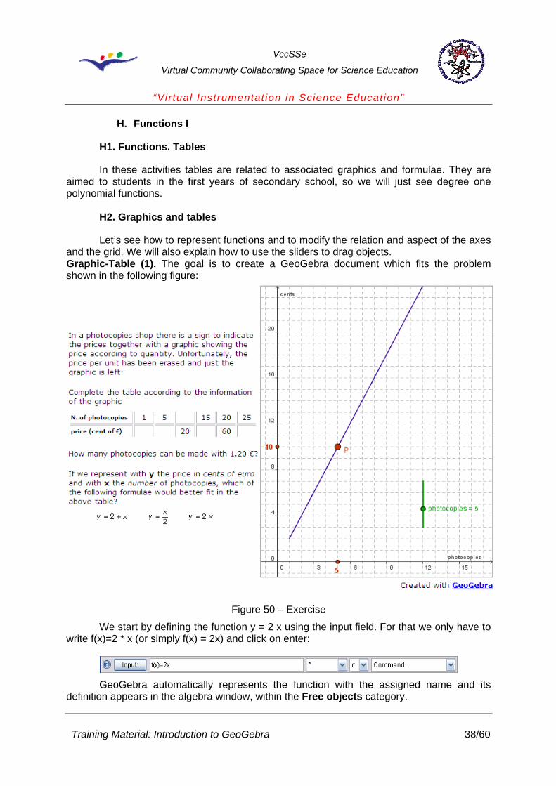
Let’s see how to represent functions and to modify the relation and aspect of the axes and the grid. We will also explain how to use the sliders to drag objects. Graphic-Table (1). The goal is to create a GeoGebra document which fits the problem shown in the following figure:
Figure 50 – Exercise
We start by defining the function y = 2 x using the input field. For that we only have to write f(x)=2 * x (or simply f(x) = 2x) and click on enter:
GeoGebra automatically represents the function with the assigned name and its
definition appears in the algebra window, within the Free objects category.
Training Material: Introduction to GeoGebra 38/60

VccSSe
Virtual Community Collaborating Space for Science Education
“Virtual Instrumentat ion in Science Education”
Figure 51 – Exercise
In the Properties window of the function f, tab, we have increased the Line
thickness to improve visualization, and in the tab we have chosen red.
Training Material: Introduction to GeoGebra 39/60

VccSSe
Virtual Community Collaborating Space for Science Education
“Virtual Instrumentat ion in Science Education”
Figure 52 – The Properties window
In the Drawing Pad window, tab, subtab, we have activated the
Numbers cell and inserted 3 in the Distance field. In the subtab, the same operations have been made but for inserting 4 in the Distance field instead. In both cases the texts for the axes have been placed in the Label field.
Figure 53 – The Drawing Pad window
Finally, in the tab, we have activated the Distance cell with the values x = 1, y = 1.
Training Material: Introduction to GeoGebra 40/60

VccSSe
Virtual Community Collaborating Space for Science Education
“Virtual Instrumentat ion in Science Education”
Figure 54 – Set de distance
We add a slider so that the position of the point P is still to be determined by the value of this parameter.
To define a Slider, place the cursor on the drawing pad and click on the corresponding button (button 6 in the tool bar, option 6). We change the name to photocopies (you can also use the command Rename for this purpose). From the Properties window of the defined slider we modify some of its features by selecting the corresponding tab.
Figure 55 – Slider features
Interval min: minimum value of the associated number. max: maximum value. Increment: number to be added to the present value of the slider when it moves.
Slider fixed: it avoids the control movement through the window.
Training Material: Introduction to GeoGebra 41/60

VccSSe
Virtual Community Collaborating Space for Science Education
“Virtual Instrumentat ion in Science Education”
vertical/horizontal: control orientation. Width: control width.
Figure 56 – The Properties window
The properties related to colour and style are modified by activating the corresponding tabs in the same way we have already explained for other objects.
In order to move the point P according to the value of the slider and on the line, we define it in the input line:
P=(photocopies,f(photocopies)) That is to say, the x-coordinate is provided by the value placed in the slider and the y-
coordinate is calculated by the defined function. A P point can also be defined in any position, and change its definition later. If instead of dragging the point with the slider we want to move it freely on the line,
you just have to choose the tool New Point and move the cursor around the graphic until the label Function f appears. If we check the definition now we will see P = Point [f]. Thus, the point is linked to the line and it is not possible to drag it outside it.
To limit the definition command of the function, like in the one described, we have to use the command Function (from the input line)
Function[f, a, b] where a and b are the limits of the definition interval of the function. Next, we are going to
hide the original function f ( ). GeoGebra defines a new function g equal to f in the definition interval. The properties
of this new function can be modified as usual. To finish, we can see that in the GeoGebra file the x-coordinate and the y-cooordinate
values on the corresponding axes appear in red. To achieve this effect you just have to define two points A(x(P), 0) y B(0, f(x(P)) and change their properties (colour and style).
The labels attached to these two points show the abscise and ordinate values of P and they are created with the command Insert text defining its position according to the coordinates of the point P.
Points Text of the label Position of the label
Training Material: Introduction to GeoGebra 42/60
VccSSe
Virtual Community Collaborating Space for Science Education
“Virtual Instrumentat ion in Science Education”
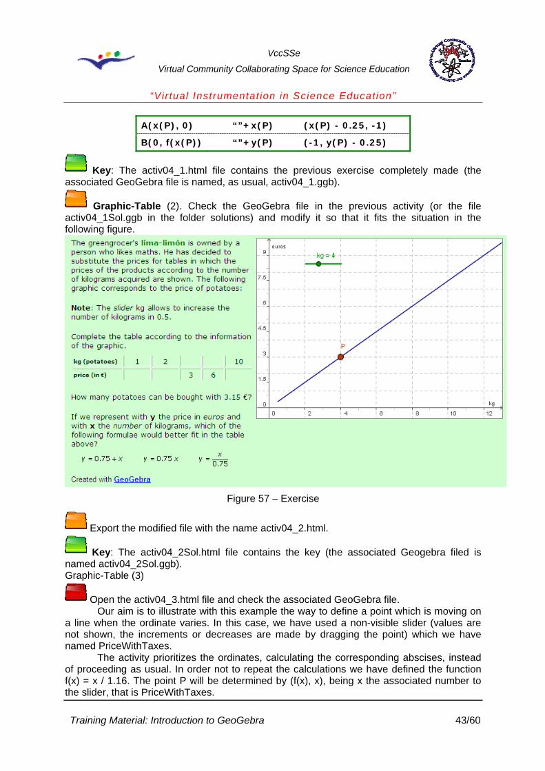
A(x(P), 0) “”+x(P) (x(P) - 0.25, -1)
B(0, f(x(P)) “”+y(P) (-1, y(P) - 0.25)
Key: The activ04_1.html file contains the previous exercise completely made (the associated GeoGebra file is named, as usual, activ04_1.ggb).
Graphic-Table (2). Check the GeoGebra file in the previous activity (or the file activ04_1Sol.ggb in the folder solutions) and modify it so that it fits the situation in the following figure.
Figure 57 – Exercise
Export the modified file with the name activ04_2.html.
Key: The activ04_2Sol.html file contains the key (the associated Geogebra filed is named activ04_2Sol.ggb). Graphic-Table (3)
Open the activ04_3.html file and check the associated GeoGebra file. Our aim is to illustrate with this example the way to define a point which is moving on
a line when the ordinate varies. In this case, we have used a non-visible slider (values are not shown, the increments or decreases are made by dragging the point) which we have named PriceWithTaxes.
The activity prioritizes the ordinates, calculating the corresponding abscises, instead of proceeding as usual. In order not to repeat the calculations we have defined the function f(x) = x / 1.16. The point P will be determined by (f(x), x), being x the associated number to the slider, that is PriceWithTaxes.
Training Material: Introduction to GeoGebra 43/60

VccSSe
Virtual Community Collaborating Space for Science Education
“Virtual Instrumentat ion in Science Education”
Graphic-Table (4) Modifies the GeoGebra file making that every increment of the slider corresponds to a
5 unit movement in the abscise axis (see figure). Change the name of the slider for PriceWithoutTaxes and add the value of the slider in the label.
Remember that the function to be used in this case is the one called g (g(x) = 1.16 x).
Save the modified file with a different name and export it with the name activ04_4.html.
Figure 58 – Exercise
Key: The activ04_4Sol.html file contains a key. The associated Geogebra file is named activ04_4Sol.ggb.
H3. Tables and graphics
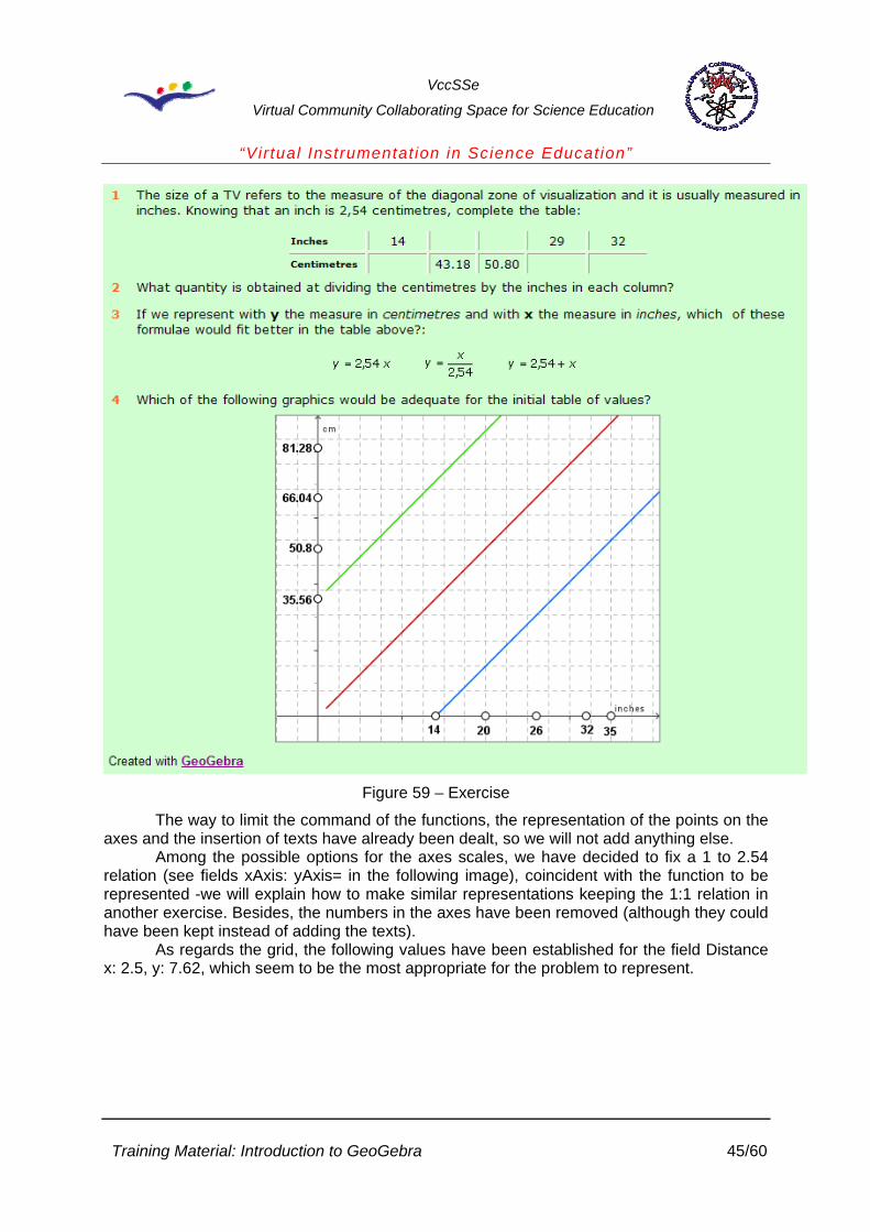
Open the activ04_5.html file. The thing is to identify the function corresponding to the statement.
Training Material: Introduction to GeoGebra 44/60
VccSSe
Virtual Community Collaborating Space for Science Education
“Virtual Instrumentat ion in Science Education”
Figure 59 – Exercise
The way to limit the command of the functions, the representation of the points on the axes and the insertion of texts have already been dealt, so we will not add anything else.
Among the possible options for the axes scales, we have decided to fix a 1 to 2.54 relation (see fields xAxis: yAxis= in the following image), coincident with the function to be represented -we will explain how to make similar representations keeping the 1:1 relation in another exercise. Besides, the numbers in the axes have been removed (although they could have been kept instead of adding the texts).
As regards the grid, the following values have been established for the field Distance x: 2.5, y: 7.62, which seem to be the most appropriate for the problem to represent.
Training Material: Introduction to GeoGebra 45/60

VccSSe
Virtual Community Collaborating Space for Science Education
“Virtual Instrumentat ion in Science Education”
Figure 60 – The Drawing Pad window
We have defined the functions f, g, h (and the corresponding ones which limit the command f1, g1, h1, the ones shown in the graphic)
f(x) = 2.54 x, g(x) = f(x) + f(14), h(x) = f(x) –f(14) As you can see in the algebra window, these new functions belong to the Dependent
objects category since another object is involved in its definition. Points on the axes
X_1 = (14,0), X_2 = (20,0) … X_5=(35,0) Y_1 = (0, f(x(X_1))), …, Y_4 = (0, f(x(X_4)))
Remember that X_1 turns into X1 in the GeoGebra window. On the other hand, x(X_1) represents the abscise of the point X1, so f(x(X_1)) will be the y-coordinate in the function f.
For the texts, proceed as in the previous exercises: once the Insert text tool is selected, place the cursor around the point and write the text. For instance, for the label 35.56 in the yAxis we should type “”+y(Y_1), while for the label 14 in the xAxis, we should type “”+x(X_1). Both the defined points and the labels have turned into fixed objects to avoid movement.
We must remark that the functionality of the exercise is kept without the need of adding the points and texts already mentioned. We could activate the field Numbers in the Drawing Pad window and use the appearing values.
Training Material: Introduction to GeoGebra 46/60

VccSSe
Virtual Community Collaborating Space for Science Education
“Virtual Instrumentat ion in Science Education”
Figure 61 – Exercise
H4. Tables and identification of graphics In this exercise a slider is used to show a set of graphics so that the student will be
able to identify the one corresponding to a given situation.
Open the activ04_6.html file. The slider allows to draw 4 lines, the ones corresponding to the family f(x) = 4 - sx, where s can take the values 1, 2, 3, 4.
Figure 62 – Exercise
For this activity an a slider has been defined (hidden label, green colour, style 5, min: 1, max: 4, Increment: 1) and a function f(x) = 4 – ax. The labels of the axes have been defined by means of the Insert text command fitting the values to the conditions of the problem.
Design an activity to identify the graphic of the family y = 2 + bx, where b takes values among -2 and 2 (increment 0.5). Use a slider to start changing the graphic.
Training Material: Introduction to GeoGebra 47/60

VccSSe
Virtual Community Collaborating Space for Science Education
“Virtual Instrumentat ion in Science Education”
Save the file naming it as activ04_7.ggb. Use the command export to generate an html file named as activ04_7.html.
Key: It is enough to modify the definitions of the slider and the one of the function to adapt them to the new situation. The activ04_7Sol.html file contains a key (the associated GeoGebra file is named activ04_7Sol.ggb).
H5. Some exercises about lines
The files activ04_8.html, activ04_9.html and activ04_A.html set out exercises where tables, formulae, graphics and verbal description of functions are used. They can be easily solved with what has been previously stated.
The activ04_8.html file presents a modification of the function to be represented, very usual when using the blackboard or the notebook to represent the functions. The function to be represented is f(x) = 0.6 x, but the one that is really represented is f(x) = 1.2 x. This situation holds good as an example to insist on the graphical representation of functions when the divisions of the axes are not adapted to the visualization necessities.
In general, computer applications need adjustments so that the representation fits the data visualized. If we had used the original function it would have been impossible to match the used divisions in the axes and the graphic of the function.
The following image shows the point P under the restriction of being dragged on the line.
f(x) = 0.6 x, The segments corresponding to the coordinates have been drawn to ease the
visualization of the difference among the reality of the function and what we have represented.
As expected, GeoGebra represents the point P(3,1.8) corresponding to f(x) = 0.6 x.
Figure 63 – Point P under restriction
Training Material: Introduction to GeoGebra 48/60

VccSSe
Virtual Community Collaborating Space for Science Education
“Virtual Instrumentat ion in Science Education”
Figure 64 - Exercise
But what we really want to represent is the point P(3,3.6) belonging to the graphical function
g(x) = 1.2 x You can always define the original function and use it for the function which fits the
measures we want to represent on the axes. In the example,
g(x) = 2 * f(x)
I. Functions II
I1. Polynomial functions and their graphics
In these activities we will analyze the polynomial functions and the shapes of their graphics. The GeoGebra functionalities to carry out these exercises have already been explained. Remember that the usual way to introduce the functions is by means of the edit line or input field.
Open the activ05_1.html file. The thing is to compare the graphics of the functions belonging to the type f(x) = xn, depending on whether n is even or odd.
Compare the graphics of the functions y = x2, y = x4 and y = x6 with the graphics of y = x3 and y = x5 and write the similarities and/or differences between the ones in the first group and the ones in the second.
Note: The slider n allows you to visualize the graphics of the functions above.
Training Material: Introduction to GeoGebra 49/60

Virtual Comm
VccSSe
unity Collaborating Space for Science Education
“Virtual Instrumentat ion in Science Education”
As it has been shown in the graphics above, if n is any positive integer, describe as detailed as possible the aspect of the graphic of the functions of the type
f(x) = xn, according to whether n is even or odd.
Which of the following graphics correspond to the functions of the type f(x) = xn with n even? And with n odd?
We have defined an n slider (for integer values between 2 and 6) and the function
f(x) =xn is represented with the corresponding text.
Training Material: Introduction to GeoGebra 50/60

VccSSe
Virtual Community Collaborating Space for Science Education
“Virtual Instrumentat ion in Science Education”
Open the activ05_2.html file. The thing is to draw conclusions on the influence of the sign k in the graphics of the function belonging to the type f(x) = (x – k)2.
Describe in detail the characteristics of the graphics of the functions y = (x - k)2, being k any nonzero real number.
Note: The slider k allows you to visualize the graphics of the functions above for the values of k among -4 and 4.
Describe in detail the influence which the sign k has in the graphic of the functions f(x) = (x - k)2 Identify which of the following graphics correspond to the functions of the type f(x) = (x - k)2 with k positive and with k negative.
We have defined a k slider (for integer values among -4 and 4), the function f(x) = (x-k)2 and the corresponding text.
To avoid the visualization of f(x) = (x-0)2 we have included two texts. The first, adequate for all values of k but for 0 - "f(x) = " + f – and the second which can only be visualized when k = 0 - f(x) = x^2. To get this effect you just have to impose the conditions shown in the tab in the Properties window of the corresponding object.
Figure 65 – The Advanced tab in the Properties window
Training Material: Introduction to GeoGebra 51/60

VccSSe
Virtual Community Collaborating Space for Science Education
“Virtual Instrumentat ion in Science Education”
Open the activ05_3.html file. The thing is to draw conclusions on the influence of the sign k in the graphics of the functions belonging to the type f(x) = kx2.
Describe in detail the characteristics of the graphics of the functions y = kx2, being k any nonzero real number.
Note: The slider k allows you to visualize the graphics of the functions above for the values of k between -3 and 3.
Describe in detail the influence which the sign k has in the graphic of the functions f(x) = kx2. Identify which of the following graphics correspond to the functions of the type f(x) = kx2 with k positive and with k negative.
We have defined a k slider (for integer values among -3 and 3 with 0.5 increments),
the function f(x) = kx2 and the corresponding text. In this case the exception is applicable both to the text and the function f.
Training Material: Introduction to GeoGebra 52/60

VccSSe
Virtual Community Collaborating Space for Science Education
“Virtual Instrumentat ion in Science Education”
Open the activ05_4.html file. The thing is to draw conclusions on the influence of the sign k in the graphics of the functions belonging to the type f(x) = x2 + k.
We have defined a k slider (for values betweens -4 and 4), the function f(x) = x2 + k and the corresponding text with similar restrictions to the previous exercise (see image).
Describe in detail the characteristics of the graphics of the functions y = x2 + k, being k
any nonzero real number. Note: The slider k allows you to visualize the graphics of the functions above for the
values of k between -4 and 4.
Describe in detail the influence which the sign k has in the graphic of the functions f(x) = x2 + k Identify which of the following graphics correspond to the functions of the type f(x) = x2 + k with k positive and with k negative.
Training Material: Introduction to GeoGebra 53/60

VccSSe
Virtual Community Collaborating Space for Science Education
“Virtual Instrumentat ion in Science Education”
Open the activ05_5.html file. The thing is, according to the previous exercises, to draw conclusions on the influence of the signs a, b and c in the graphics of the functions of the type f(x) = a (x – b)2 + c We have defined two sliders b and c (for values between -4 and 4), the function
f(x) = a (x – b)2 + c and the corresponding texts similar restrictions to the previous exercises.
Describe in detail the characteristics which the graphics of the functions y = a(x - b)2 + c,
should have being a, b and c real numbers with a nonzero. Note: The sliders b and c allows you to visualize the graphics of the functions above for
the values b and c between -4 and 4.
Describe in detail the influence the parameters a, b and c have on the graphic of the functions f(x) = a(x - b)2 + c referring to the sign. Identify which of the following graphics corresponds to the function f(x) = (x -2)2 + 2 and which corresponds to f(x) = -(x +2)2 - 2.
Training Material: Introduction to GeoGebra 54/60

VccSSe
Virtual Community Collaborating Space for Science Education
“Virtual Instrumentat ion in Science Education”
We have defined a number n using the GeoGebra function random which generates a random number between 0 and 1: n = random()
The coefficient a can only take the values 1 and -1. To define it we have used the auxiliary number n previously generated jointly with the conditional:
If [n < 0.5, 1, -1] The syntax of the conditional is the following: If [condition, action_1, action_2],
where action_1 is performed when condition is true and action_2 when it is false. The symbol reset -mark the cell Show icon to reset construction, in the tab in the Export: Dynamic Worksheet (html) window- generates again the number n and, thus, the value of a.
Figure 66 – The Properties window
A different way to make this exercise: Define b and c as random integers with values between -4 and 4 and write their values. To change the values of the coefficients we must use then the symbol reset.
The definitions of b and c, would be: b = ceil(8 random() - 4) c = ceil(8 random() - 4)
The same procedure could have been used in the previous exercises.
Figure 67 – Exercise
Training Material: Introduction to GeoGebra 55/60

VccSSe
Virtual Community Collaborating Space for Science Education
“Virtual Instrumentat ion in Science Education”
J. How to insert the random function in a GeoGebra applet
Although you can use the random function, GeoGebra turns the objects in which this function is involved into dependent objects so that it is not possible for them to be dragged with the mouse.
As an alternative, let’s see how to insert random objects by modifying the code in an html page containing a GeoGebra applet.
We will start by using the activ03.html as basis.
You can use any text editor, but we will use FrontPage 2003. In the File menu, select the command Open or just click on the Open icon.
The Open File window is displayed, search the folder which contains the file and select it.
Figure 68 – The Open window
Click on the Code tab at the bottom of the window and we will see how the web page code is.
Training Material: Introduction to GeoGebra 56/60

VccSSe
Virtual Community Collaborating Space for Science Education
“Virtual Instrumentat ion in Science Education”
Figure 69 – The web page code
The part of the code corresponding the GeoGebra applet is:
Figure 70 – The GeoGebra applet
This method consists on 3 steps: Step 1: Name the applet to be easily found.
Let’s place the cursor of the mouse between the words applet and code. Then write:
name=”applet_ticmates” as it can be seen in the following figure.
Training Material: Introduction to GeoGebra 57/60

VccSSe
Virtual Community Collaborating Space for Science Education
“Virtual Instrumentat ion in Science Education”
Figure 71 – Name the applet
Step 2: Just under the applet code we will insert the JavaScript code which will enable us to calculate a integer number by random and pass it to the applet to place the points A, B, C and D regarding the random coordinates, generated every time you load or refresh the web page.
Copy the following code: <script type="text/javascript">
//function to obtain an integer among -6 and 6
function entero_azar(){
var el_entero = Math.floor(Math.random()*(13)-6);
return el_entero;
}
//Function to assign ramdom values to points A, B, C & D
//it will be called from the "body" tag after loading the page
function coordenadas_puntos_azar(){
var applet=document.ticmates;
applet.evalCommand("A = (" + entero_azar() + ", " + entero_azar() + ")");
applet.evalCommand ("B = (" + -entero_azar() + ", " + entero_azar() + ")");
applet.evalCommand ("C = (" + -entero_azar() + ", " + -entero_azar() + ")");
applet.evalCommand ("D = (" + entero_azar() + ", " + -entero_azar() + ")");
}
</script>
And we paste it under the applet code as shown in the following figure:
Training Material: Introduction to GeoGebra 58/60

VccSSe
Virtual Community Collaborating Space for Science Education
“Virtual Instrumentat ion in Science Education”
Figure 72 – Insert the JavaScript code
Step 3: In order that the web page can execute the function coordenadas_puntos_azar() from the added code, we must modify the content of the tag body
Write (in between the quotation marks) onload="coordenadas_puntos_azar()" as
shown in the following figure:
Once these three steps have been accomplished we can save the file, activ03Random.html.
Key: The activ03RandomSol.html file contains a key. To check the result we will open the folder with the browser to ensure that the points are placed by random every time we open or refresh the web page. In the way we have defined the function coordenadas_puntos_azar, the coordinates of the points A, B, C and D take values in the intervals that are shown in the following table:
A B C D
x [1, 5] [-1, -5] [-1, -5] [1, 5]
y [1, 5] [1, 5] [-1, -5] [-1, -5]
You can check some more examples about the use of JavaScript in this url:
http://www.geogebra.org/source/program/applet/geogebra_applet_javascript.html
Training Material: Introduction to GeoGebra 59/60

VccSSe
Virtual Community Collaborating Space for Science Education
“Virtual Instrumentat ion in Science Education”
Training Material: Introduction to GeoGebra 60/60
K. References
[1] The Geogebra web site: http://www.geogebra.org/ [2] Hohenwarter Markus, Hohenwarter Judith, Introduction to Geogebra, second
edition, Unites States, 2008; [3] Geogebra, http://notropis.net/geogebra/