Geodetic Aircraft Structure - Freea.moirier.free.fr/Conception/Conception/Geodetic aircraft... ·...
6
PART TWO Geodetic Aircraft Structure By Keith D. Powell, EAA 1939 Economy and Ease of Construction. Mr. Player's quotation of $500. cost for constructing the "Player" is indicative of the economy geodetic pro- vides. This quotation is at the 1939 dollar value but even today comparable cost cannot be matched by other materials. The geodetic strips are sawed from a good straight grain spruce plank. Much cheaper than aircraft plywood and aluminum sheet or steel tubing. Earl says the "Play- er" fuselage material cost about $10.00. Compare this to the $300.00 or more required for steel tubing used in the average two-place available homebuilt such as the Tailwind, Cougar, Skyhopper, and most others. Simple tools are required. The average handyman or hobbyist should have drills, a bench saw, a saber saw and the necessary hand tools. Planing mills and cabinet shops are readily available and reasonable for the small amount of heavy "finishing" that may be required. Thai- man used large spring clothes pins as clamps in gluing the geodetic spirals. Earl constructed the "Player" in less than a year without previous aircraft building ex- perience. Ingenuity rather than several special skills, fancy tools and expensive material seems to be the answer here. Details of Construction. The foregoing indicates what can be done. Now let's see how we can do it with a few technical tips mentioned by the experts. Looking at an uncovered geodetic fuselage it seems to be an intricate maze of criss-crossed thin strips spiral- ing hither and yon in a most confusing manner. Closer inspection reveals the maze to have a definite pattern and lo and behold the strips are not woven over and under as the common term "Basket-weave" leads one to believe. See Fig. 6 and more on this later. Looking deeper inside the structure we see bulkheads and formers with a longeron or two at cutouts such as the cockpit openings, high load carrying points, etc. The geodetic strips are, in function, the stressed skin of our structure but a little ground work is neces- sary to provide a place for them so let's start with the innards. Bulkheads and Formers. We deal with the fuselage only now with the thought that references to formers and longerons will apply, in kind, the same as would ribs and spars for a wing. The bulkheads and formers must be constructed first and as the sketches show, several methods are available in design and construction. A combination of two or more types can be used in one fuselage. The "Player" has only one type (Fig. 7) and is the easiest to build. All were cut from marine plywood sheet, graduating in thickness from nose to tail, utiliz- ing "beef" in the load carrying areas of the forward sec- tion and thinner lighter material for the aft. We quote GUlt /*"• OVtK LAPf-ffAILS 1M fiHMOIT - CtJtfCflfO oA FKtssvaf Fig. 6 from the ANC-19 Bulletin, "Fuselage rings or bulkheads are frequently cut out of solid plywood or utilize plywood webs in combination with other parts. In either in- stance the plywood is most easily cut to shape by rout- ing. Fuselage rings for one plane model have been made by band sawing from plywood with reportedly satisfactory results in service. Excellent utilization was reputedly attained by cutting a series of rings of successively de- creasing size from the same sheet of plywood and, in addi- tion, using small scraps for other purposes." Unquote. A proven, simple, and economical method of fabrication for the homebuilt it seems. Wood end grain provides a weak glue joint and at least 50% of the sawed or routed former edge receiving the geodetic strips is end grain. Small glue blocks added as shown in Fig. (7b) correct this problem. Steel straps are bolted to the plywood at important stations such as the landing gear and strut fitting loca- tions to relieve the wood of stresses and to transfer loads from fitting point to fitting point. Many methods are available to prevent localized stress and subsequent failure of the wood fibers. All rules of good design en- gineering must be followed of course. Typical methods used to spread stress over as large an area as possible are high density reinforcement plates of birch plywood, compreg, impreg, or hardwood inserts; metal plates, large wood washers, bolt bushings, etc. The EAA Builder's Manuals, and SPORT AVIATION back issues contain a wealth of information on this subject as well as the aforementioned ANC Bulletins. The Thalman ships use the more intricate laminated and built-up bulkheads and formers. (Fig. 7c). Though more trouble to build, they feature greater strength with light weight and are recommended for the advanced designer-builder. Thin strips of Vs in. thick spruce are glued up on a mold to form the laminated ring type former (Fig. 8). Very light rings are used in the aft fuselage. continued on page 16 SPORT AVIATION 15
Transcript of Geodetic Aircraft Structure - Freea.moirier.free.fr/Conception/Conception/Geodetic aircraft... ·...
PART TWO
Geodetic Aircraft StructureBy Keith D. Powell, EAA 1939
Economy and Ease of Construction.Mr. Player's quotation of $500. cost for constructing
the "Player" is indicative of the economy geodetic pro-vides. This quotation is at the 1939 dollar value buteven today comparable cost cannot be matched by othermaterials.
The geodetic strips are sawed from a good straightgrain spruce plank. Much cheaper than aircraft plywoodand aluminum sheet or steel tubing. Earl says the "Play-er" fuselage material cost about $10.00. Compare thisto the $300.00 or more required for steel tubing usedin the average two-place available homebuilt such as theTailwind, Cougar, Skyhopper, and most others.
Simple tools are required. The average handymanor hobbyist should have drills, a bench saw, a saber sawand the necessary hand tools. Planing mills and cabinetshops are readily available and reasonable for the smallamount of heavy "finishing" that may be required. Thai-man used large spring clothes pins as clamps in gluingthe geodetic spirals. Earl constructed the "Player" inless than a year without previous aircraft building ex-perience. Ingenuity rather than several special skills,fancy tools and expensive material seems to be theanswer here.
Details of Construction.The foregoing indicates what can be done. Now
let's see how we can do it with a few technical tipsmentioned by the experts.
Looking at an uncovered geodetic fuselage it seemsto be an intricate maze of criss-crossed thin strips spiral-ing hither and yon in a most confusing manner.
Closer inspection reveals the maze to have a definitepattern and lo and behold the strips are not woven overand under as the common term "Basket-weave" leadsone to believe. See Fig. 6 and more on this later.
Looking deeper inside the structure we see bulkheadsand formers with a longeron or two at cutouts such asthe cockpit openings, high load carrying points, etc.
The geodetic strips are, in function, the stressedskin of our structure but a little ground work is neces-sary to provide a place for them so let's start with theinnards.
Bulkheads and Formers.We deal with the fuselage only now with the thought
that references to formers and longerons will apply, inkind, the same as would ribs and spars for a wing. Thebulkheads and formers must be constructed first andas the sketches show, several methods are available indesign and construction. A combination of two or moretypes can be used in one fuselage.
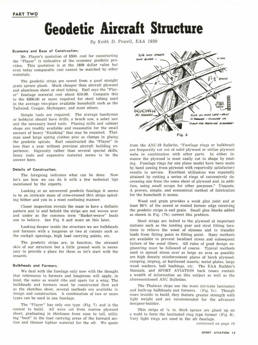
The "Player" has only one type (Fig. 7) and is theeasiest to build. All were cut from marine plywoodsheet, graduating in thickness from nose to tail, utiliz-ing "beef" in the load carrying areas of the forward sec-tion and thinner lighter material for the aft. We quote
GUlt /*"• OVtK LAPf-ffAILS1M fiHMOIT - CtJtfCflfO oA
FKtssvaf
Fig. 6
from the ANC-19 Bulletin, "Fuselage rings or bulkheadsare frequently cut out of solid plywood or utilize plywoodwebs in combination with other parts. In either in-stance the plywood is most easily cut to shape by rout-ing. Fuselage rings for one plane model have been madeby band sawing from plywood with reportedly satisfactoryresults in service. Excellent utilization was reputedlyattained by cutting a series of rings of successively de-creasing size from the same sheet of plywood and, in addi-tion, using small scraps for other purposes." Unquote.A proven, simple, and economical method of fabricationfor the homebuilt it seems.
Wood end grain provides a weak glue joint and atleast 50% of the sawed or routed former edge receivingthe geodetic strips is end grain. Small glue blocks addedas shown in Fig. (7b) correct this problem.
Steel straps are bolted to the plywood at importantstations such as the landing gear and strut fitting loca-tions to relieve the wood of stresses and to transferloads from fitting point to fitting point. Many methodsare available to prevent localized stress and subsequentfailure of the wood fibers. All rules of good design en-gineering must be followed of course. Typical methodsused to spread stress over as large an area as possibleare high density reinforcement plates of birch plywood,compreg, impreg, or hardwood inserts; metal plates, largewood washers, bolt bushings, etc. The EAA Builder'sManuals, and SPORT AVIATION back issues containa wealth of information on this subject as well as theaforementioned ANC Bulletins.
The Thalman ships use the more intricate laminatedand built-up bulkheads and formers. (Fig. 7c). Thoughmore trouble to build, they feature greater strength withlight weight and are recommended for the advanceddesigner-builder.
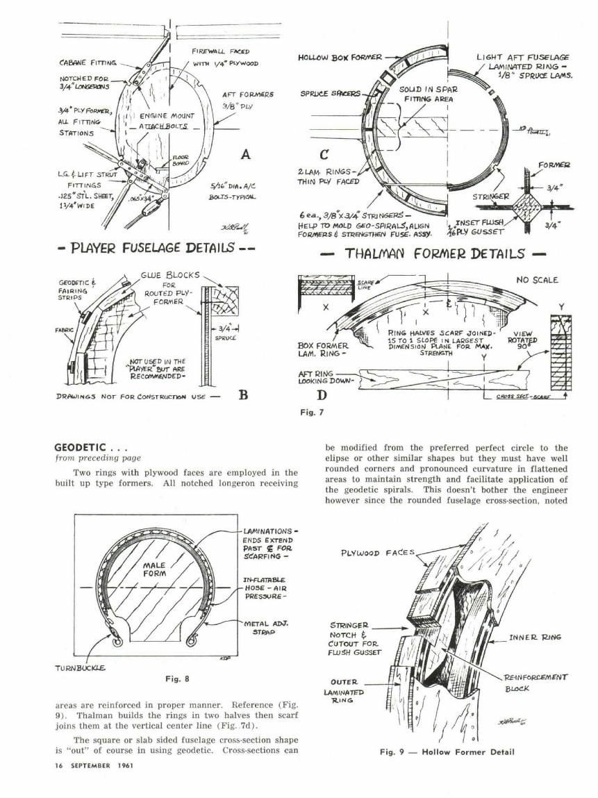
Thin strips of Vs in. thick spruce are glued up ona mold to form the laminated ring type former (Fig. 8).Very light rings are used in the aft fuselage.
continued on page 16
SPORT AVIATION 15
WITH 1/4" PLX WOOD
UG. £ Li F T STRUTFITTINGS
J25*STL. SHSET,
- PLAYER FUSELAGE DETAILS —
GLUE BLOCKSFOE
ROOTb'D PL.y-FORMER
NOT USED IN THE' PIAVER*BWT ARE
DRAWINGS NOT FOR CONSTRUCTION vse — B
HOLLOW BOX
SPRJXE
LIGHT AFT FUSELAGELAM/MATED
1/8" SPRUCE
j ••-/*_/ ^*>-V*T wr i r̂ i > w- • — j/^^^J
TO MOLD 6tO-SP/«AU?,flLIGN 'l.*̂ !?^ ft- •"
— THAI/WJ FORMER DETAILS —
NO SCALE
RING HALVES SCARF JOINED- VIEW15 TO 1 SLOPE 1M LABGEST ROTATEDDIMENSION PLAME FOR *"~ °"*
STRENGTHBOX FORMERLAM. RlNG-
AFTCIf^SLOOKING DOUW- P
DFig. 7
GEODETIC . . .from preceding page
Two rings with plywood faces are employed in thebuilt up type formers. All notched longeron receiving
LAW/NATIONS •ENDS EXTENDPAST <g FOR
HOSE-AIRPRESSURE -
METAL ADJ.ST&iP
TURNBOC«X£Fig. 8
areas are reinforced in proper manner. Reference (Fig.9). Thalman builds the rings in two halves then scarfjoins them at the vertical center line (Fig. 7d).
The square or slab sided fuselage cross-section shapeis "out" of course in using geodetic. Cross-sections can16 SEPTEMBER 1961
be modified from the preferred perfect circle to theelipse or other similar shapes but they must have wellrounded corners and pronounced curvature in flattenedareas to maintain strength and facilitate application ofthe geodetic spirals. This doesn't bother the engineerhowever since the rounded fuselage cross-section, noted
PLY WOOD
STRINGERNOTCHCUTOUT FOR.
GUSSET
OUTER.LAAt/NATFP
•RINA
Fig. 9 — Hollow Former Detail

&s sf<f -
ROTATIONLOOC
GEO-SPtRAL
FULL SWIVELDETACHABLE
STANJJS
IWOODCOMPLETED SHELL REMOVED REARWARD
FORMER. RINGS COMPED TOWOOD SUPPORTS PRE-ALIGNED $SECURED ON -J IS FRAME AT FUSE.STATIONS •—
Fig. 10
for aerodynamic efficiency (looks pretty too), is madeto order. Streamlining is built in eliminating the re-quirement for "weighty", non-functional, superstructuresas used in some other airframe types.
Assembly Jig.With the formers complete some sort of fixture will
be needed to continue assembly. Since the strips arewrapped around the outside of the formers an internaljig must be used.
Player spotted the formers by hanging them on aplank, braced them in position then attached four % in.square spruce longerons in the pre-notched formers tostart construction and tie things together. The geodeticstrip application followed and when complete, the plankand internal bracing were removed. The four longeronsremained a part of the structure. Earl cautions that
some twisting problems developed during the spiralstrip application and recommends that the assemblyfixture used be completely rigid to prevent trouble.
Mr. Thalman also used an internal assembly fix-ture made up of a scrap wood 2 x 2 truss framework withscrap plywood gusseted joints, (Fig. 10). Remember theway we built the old balsa stick slab sided modelfuselages? Two sides, then put in the cross pieces?The truss frame jig is supported with a pivot point ateach end so the whole assembly can be rotated 360 deg.for ease in working. Formers are attached at theirrespective stations and construction started. After com-pletion the jig is disassembled and removed.
Many other methods undoubtedly would work suchas the crutch and half bulkhead system as used inmodeling, or ??? (The old ingenuity factor again.) Wing
continued on page 18SPORT AVIATION 17
GEODETIC . . .from preceding pagespars and ribs properly supported are actually the jigfor assembly of these components.
Wings.At the risk of being incongruous in our step by step
fabrication of a fuselage (and to break the monotony)here is the answer to the inevitable question: "How isgeodetic used in building a wing?"
The Thalman geodetic full cantilever wing (Fig. 11)consists of one main box spar at about 25% chord, a rear
TRUSS1 OR Pty RJ85STRINCERS
Fig. 11
spar to which the flaps and ailerons attach and a smallfalse spar very close to the leading edge. Ribs arespaced at 32 to 36 in. intervals. Stringers of % by %in. dimension run spanwise to align and support ribsbetween the spars.
The geodetic "skin" can be applied on the wing topand bottom in the same manner as the fuselage withthe exception that strips are not continuous around theleading edge but terminate at the rear spar and L. E. falsespar. Harry builds the diamond mesh "skins" flat on theshop floor. For all surfaces other than the fuselage,this method provides faster lattice assembly and attach-ment. Attachment is similar to the plywood coveredwing skinning procedures. The novel exception is thatyou can see where the nails are going, the glue squeezeout and all the other "hidden" details not discernableduring and after skinning with plywood.
A thin plywood or light aluminum leading edgecovering and the fairing strips are added over the geo-detic before the final fabric cover. Use of monospar,"D" spar, lift strut or flying wire braced wing variationsof the Thalman system with proper design engineeringwould be practical.
Not to knock geodetic, but in the interest of "go-grease" for the really high performance airplane, Harry18 SEPTEMBER 1941
LflM/NATET) RINGBUILT UP FOHMEP.
so* V f^EP- -̂ V
NO SCfcLE
1/16* PLYWOOD FACED
BOX
/' '/'I ^ '/Al .;'/
FORM* ft* - Rolt. StiltsADDED L.A3TT ——
Fig. 12 — Box Longeron • Cabin Framing Detail
recommends the use of the all plywood covered wingwith its smooth, airfoil preserving surface and aerodyna-mic efficiency. Using wings of geodetic, the ultra-lightor Sunday "sportster" would reap other and possiblymore important benefits. Designed and constructedcarefully geodetic wings are superior or equal to the plycovered in strength, weight and other respects. The standout and possibly determining factor again in its usewould be the savings in cost of material.
Now back to the fuselage.
Framing of Cut-Outs.The perfect geodetic structure, strengthwise, would
be one without any cut-outs for cockpits, passengercompartments, wing or tail junctures; however this isimpossible so such openings or breaks in the "stressedskin" must be framed and re-inforced.
It's up to the builder to determine the type of fram-ing he needs. The "Player", a parasol monoplane withonly the cockpit opening breaking the geodetic, requireda simple plywood sheet framing. The 3/32 in. plywoodwas glued over the geodetic strips in the pre-determinedarea, then the cockpit opening was marked and cutthrough the ply and the strips in one simple operation.
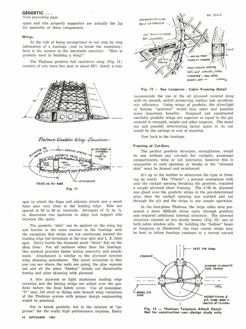
In the four-place Thalman, the large cabin area pre-sented a more difficult stress carry through problemand required additional internal structure. The internalstructure consists of two sturdy beams (Fig. 12) one atboth cabin window sills. By building the "hollow" beamor longeron as illustrated, the four corner strips maybe bent to follow fuselage contours or a curved cut-out
Fig. 13 — Thalman Tailplane Attach Detail.Not for construction use—design study only.
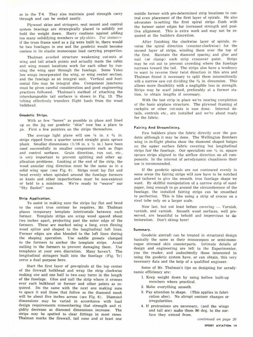
as in the T-4. They also maintain good strength carrythrough and can be ended neatly.
Plywood skins and stringers, seat mount and controlsystem bracings are strategically placed to solidify yethold the weight down. Harry cautions against addingtoo many solidifying members or ply-skins. For instanceif the truss frame used as a jig were built in, there wouldbe two fuselages in one and the geodetic would becomeuseless in its elastic monocoque load carrying properties.
Thalman avoided structure weakening cut-outs atwing and tail attach points and actually made the cabinand wing mount locations work for each other by run-ning the wing spar through the fuselage. Some Yateslow wings incorporated the wing, or wing center section,and the fuselage as an integral unit. Vertical and hori-zontal fins may be integral also. Component juncturesmust be given careful consideration and good engineeringpractices followed. Thalman's method of attaching theinterchangeable tail surfaces is shown in Fig. 13. Thetubing effectively transfers flight loads from the woodbulkhead.
Geodetic Strips.With as few "bones" as possible in place and lined
up on the jig our geodetic "skin" now has a place togo. First a few pointers on the strips themselves.
The average light plane will use Vs in. x % in.strips ripped from a quarter sawed straight grain spruceplank. Smaller dimensions (1/16 in. x >/2 in.) have beenused successfully in smaller components such as flapsand control surfaces. Grain direction, run out, etc.,is very important to prevent splitting and other ap-plication problems. Looking at the end of the strip, thewood annular ring direction must be the same as in asolid wing spar (see Fig. 6). Strips must lay flat andbend evenly when spiraled around the fuselage formersso knots and other imperfections must be non-existentor held to a minimum. We're ready to "weave" our"Sky Basket" now.
Strip Application.To assist in making sure the strips lay flat and bend
to the exact true contour he requires, Mr. Thalmanplaces temporary template intercostals between eachformer. Template strips are scrap wood spaced abouttwo inches apart, projecting past the outer edge of theformers. These are marked using a long, even flexingwood spline and shaped to the longitudinal loft lines.Former edges are also blended to the loft lines duringthe shaping operation. Use saddle gussets clampedto the formers to anchor the template strips. Avoidnailing to the formers to prevent damaging them. Usetemplates at your own discretion. Many haven't. Thelongitudinal stringers built into the fuselage (Fig. 7c)serve a dual purpose here.
Start the first layer of geo-spirals at the top centerof the firewall bulkhead and wrap the strip clockwisemaking one and one half to two easy turns in the lengthof the fuselage. Glue and nail the strip where it crossesover each bulkhead or former and other points as re-quired. Do the same with the next one making sureto space it and those that follow so the diamond meshwill be about five inches across (see Fig. 6). Diamonddimensions may be varied in accordance with loaddesign requirements remembering that strength and ri-gidity decrease as diamond dimensions increase. Thestrips may be spotted to clear fittings in most cases.Thalman marks the firewall, tail cone and at least one
middle former with pre-determined strip locations to con-trol even placement of the first layer of spirals. He alsoadvocates in-setting the first spiral strips flush withthe former outer edges for increased strength and posi-tive alignment. This is extra work and may not be re-quired at the builders discretion.
After finishing the clockwise layer of spirals, re-verse the spiral direction (counter-clockwise) for thesecond layer of strips, winding them over the top ofthe first. Maintain the diamond spacing and glue andnail (or clamp) each strip crossover point. Stripsmay be cut out to prevent crowding where the fuselagenarrows toward the tail. The strips also have a tendencyto want to reverse their twist direction in this area andThalman found it necessary to split them intermittentlywih a narrow saw cut dividing the 3/4 in. dimension. Thisallows more flexibility with a negligible loss in strength.Strips may be scarf joined, preferably at a former sta-tion, to obtain lengths if necessary.
With the last strip in place we're nearing completionof the basic airplane structure. The plywood framing ofcockpits or other cut-outs is now done. Internal de-tails, controls etc., are installed and we're about readyfor the fabric.
Fairing And Streamlining.Few builders place the fabric directly over the geo-
detic although it may be done. The Wellington Bomberswing in in-flight photos show the diamond shaped bulgeson the upper surface fabric covering but longitudinalstrips fair the fuselage. Our specialists use Vt in. squarespruce strips aligned in the airflow direction on all com-ponents. In the interest of aerodynamic cleanliness theiruse is recommended.
If the geodetic spirals are not contoured evenly insome areas the fairing strips will now have to be notchedand tailored to give the smooth, true fuselage shape wewant. By skillful manipulation of a narrow strip of sand-paper, long enough to go around the circumference of thefuselage, the installed fairing strips can be smoothedto perfection. This is like using a strip of crocus on asteel tube only on a larger scale.
Now last, but not least before covering — Varnish,varnish, and varnish. Smooth wood surfaces, well pre-served, are beautiful to behold and impervious to de-terioration. Don't skimp here!
Summary.
Geodetic aircraft can be treated in structural designbasically the same as their monocoques or semi-mono-coque stressed skin counterparts. Intimate details ofdesign and engineering are left to the Experimenter,you the reader, and undoubtedly those interested inusing the geodetic system have, or can obtain, this verynecessary data and the help of a qualified engineer.
Some of Mr. Thalman's tips on designing for aerody-namic efficiency are:
1. Keep weight down by using hollow built-upmembers where practical.
2. Make everything smooth.3. Pay attention to shape. (This applies in fabri-
cation also). No abrupt contour changes orirregularities.
4. If protrusions are necessary, (and the wingsand tail are) make them 90 deg. to the sur-face they extend from.
continued on page 20SPORT AVIATION 19

Shaping Tube Ends On A Metal LatheBy Francis H. Spickler, EAA 4209
One of the most important steps toward making a goodweld is to produce parts that fit accurately. The
writer is using a simple attachment for a metal lathe toshape tube ends to fit other tubes accurately and quicklyand at any angle.
The main body of the attachment is made of hardmaple 2 in. x 2 in. x 4 in. A % in. x 4'6 in. hexagonhead machine bolt is turned as shown for a 9 in. SouthBend metal lathe, or modified as necessary to fit thelathe available. The small piece of mild steel is fittedto the block and screwed in place in order to keep theblock in proper alignment with the compound rest at alltimes and yet permit easy exchange of blocks for form-ing any desired size of tubing.
Slide the head of the bolt in the "T" slot on the com-pound rest and slip the block on the bolt through the11/16 in. hole. Seat the block so that the piece of mildsteel slips into the "T" slot and fasten the block securelywith a washer and nut. Place a drill of the desired sizetubing in a chuck on the spindle of the lathe and drill ahole through the block. A second hole for a differentsize tube is also drilled the same way. Remove the blockfrom the lathe and split it in half by sawing on a circularsaw and the attachment is completed. As many blockscan be made as desired to prepare for tubing of varioussizes. By placing the 11/16 in. hole slightly off centera larger hole and a smaller hole can easily be accommo-dated on one block.
In using the attachment the piece of tubing is clamp-ed in place on the compound rest, the compound restis set to the desired angle and tightened. A standardreamer with the diameter of the tube against which theshaped tube will butt is mounted between centers of the
lathe. Flood the reamer with cutting oil, feed the tubeinto the turning reamer with the cross feed, and in amatter of moments one has a perfectly fitted pair oftubes.
Fitting tubes on an angle is no problem. One onlyhas to measure the angle of the center line of the tubes onthe jig or from an accurate plan, set up the compoundrest for the desired angle, and feed the tube into thereamer as it turns. The fit will be better than absolutelynecessary with less than a minute spent in making thecut.
To obtain the proper length, cut tho raw stock asclosely as possible to length, form one end, form the sec-ond end being careful to align the tube in the block sothat the two ends will be on the proper angle with eachother. Next try the tube in the jig. At this point it iseasy to measure how much must be removed to achievethe proper length. If the lathe has a graduated crossfeed it is a simple matter to remove precisely the re-quired amount. With practice one can usually cut thetube to the proper length so that it fits accurately thefirst time.
The writer first tried the idea without the mild steelguide block. It worked satisfactorily, but alignment ofthe tube was tedious, and took more time than formingthe tube end. Cutting and fastening this small itemsaves much time on setting up the tubes for forming.
Carbon steel reamers are satisfactory as long asplenty of cutting oil is used with relatively slow speeds.Of course high speed reamers will stand up better.
Be sure to remove all cutting oil before welding inaccordance with good welding practice. A
GEODETIC . . .from preceding page
5. Close exterior gaps. Keep outside air out andinside air in. Prevent leak through from onesurface to the other at control gaps.
6. The midwing is the most efficient and doesn'tneed fairings at the fuselage juncture, butsmall radii at such points help.
Looking at the T-4 you know he practices what hepreaches.
Wood geodetic for light aircraft is a safe, proven,strong, light, easy to fabricate, versatile and IN-EX-PENSIVE construction medium well suited to compoundaerodynamic form. Through intelligent use of its in-
North Pacific Aircraft Corp., Portland,Ore. geodetic plane before covering.
North Pacific geodetic aircraft ready for flight.
herent features it is hoped that the average EAA mem-ber, of modest means, may obtain his long dreamedof custom made "Set of Wings".
A couple of new "Flying Baskets" showing at oneof the not so distant future EAA Fly-ins would be pay-ment aplenty for our efforts here.
Many thanks to Mr. Player, Mr. Thalman, and allthe Ogden Chapter 58 members who helped with re-search, time, and technical advice.
20 SEPTEMBER 1961