genVHDL: Automatic HDL code generation from high...
34
TR OCIECE-07-01, Ottawa-Carleton Institute for Electrical and Computer Engineering, January 2007 genVHDL: Automatic HDL code generation from high-level XML based hardware specifications * Shahid Alam [email protected] and * Misbah Islam [email protected] Abstract In software and hardware design projects teams need to collaborate with each other by sharing their design data. When the teams are geographically apart, as is the case in new global economy, the need to share data on a daily basis becomes the norm. This paper proposes a novel scheme and implements a tool that allows sharing of hardware design data using XML based hardware specifications. This can be used as a basis for a framework for model driven architecture (MDA). Data in XML can be expressed in different forms, e.g. schematic, HDL and state machines etc, to be used by different teams. XML has more advantages than traditional documentation systems. It has standard tools support, ease of storage and retrieval, flexibility and compactness. To minimize communication traffic on internet we are using high level hardware design in XML to make it as compact as possible, without loosing much information. According to the survey this is apparently the first such effort for using XML for this purpose and implementation of this tool. A tool “genVHDL” has been designed and developed in C++ to generate VHDL code from high level XML based hardware specifications. This can be used as runtime or compile time code generation tool. The code generated has been successfully synthesized for digital circuits. A basic digital logic components library has also been implemented. This is to show that XML has the potential of becoming a vehicle for documenting high level hardware specifications. Using XML it will be easier to store, retrieve, manipulate and provide shared access to data. Currently the tool only supports VHDL code generation but it can be extended to add support for other HDL and other forms. It can easily be integrated into other tools or applications, unlike other scripting languages which need a script engine. Index Terms Code generation, hardware description languages, information sharing, XML I. INTRODUCTION Extensible Markup Language (XML) is a simple, very flexible text format derived from SGML [11] (ISO 8897:1986). Originally designed to meet the challenges of large scale electronic publishing, XML is also playing an increasingly important role in the exchange of a wide variety of data on the Web and elsewhere [6]. In the last few years, it has been successfully adopted in fields like finance, law, aeronautics, robotics, multimedia, telecommunication and software design. There is a need to * Misbah Islam is a full-time Professor in the School of Information Technology and Engineering at University of Ottawa and Professional Engineer in the Province of Ontario. Shahid Alam is a full-time Master student and member of IEEE in the department of Systems and Computer Engineering at Carleton University. 1
Transcript of genVHDL: Automatic HDL code generation from high...

TR OCIECE-07-01, Ottawa-Carleton Institute for Electrical and Computer Engineering, January 2007
genVHDL: Automatic HDL code generation from high-level XML based hardware specifications
* Shahid Alam [email protected] and * Misbah Islam [email protected]
Abstract In software and hardware design projects teams need to collaborate with each other by
sharing their design data. When the teams are geographically apart, as is the case in new global
economy, the need to share data on a daily basis becomes the norm. This paper proposes a novel
scheme and implements a tool that allows sharing of hardware design data using XML based hardware
specifications. This can be used as a basis for a framework for model driven architecture (MDA). Data in
XML can be expressed in different forms, e.g. schematic, HDL and state machines etc, to be used by
different teams. XML has more advantages than traditional documentation systems. It has standard tools
support, ease of storage and retrieval, flexibility and compactness. To minimize communication traffic on
internet we are using high level hardware design in XML to make it as compact as possible, without
loosing much information. According to the survey this is apparently the first such effort for using XML for
this purpose and implementation of this tool. A tool “genVHDL” has been designed and developed in C++
to generate VHDL code from high level XML based hardware specifications. This can be used as runtime
or compile time code generation tool. The code generated has been successfully synthesized for digital
circuits. A basic digital logic components library has also been implemented. This is to show that XML has
the potential of becoming a vehicle for documenting high level hardware specifications. Using XML it will
be easier to store, retrieve, manipulate and provide shared access to data. Currently the tool only
supports VHDL code generation but it can be extended to add support for other HDL and other forms. It
can easily be integrated into other tools or applications, unlike other scripting languages which need a
script engine.
Index Terms Code generation, hardware description languages, information sharing, XML
I. INTRODUCTION
Extensible Markup Language (XML) is a simple, very flexible text format derived from SGML [11] (ISO 8897:1986). Originally designed to meet the challenges of large scale electronic publishing, XML is also playing an increasingly important role in the exchange of a wide variety of data on the Web and elsewhere [6].
In the last few years, it has been successfully adopted in fields like finance, law, aeronautics, robotics, multimedia, telecommunication and software design. There is a need to
* Misbah Islam is a full-time Professor in the School of Information Technology and Engineering at University of Ottawa
and Professional Engineer in the Province of Ontario. Shahid Alam is a full-time Master student and member of IEEE in the
department of Systems and Computer Engineering at Carleton University.
1

TR OCIECE-07-01, Ottawa-Carleton Institute for Electrical and Computer Engineering, January 2007
formally express hardware specifications in a format that can be easily understood and shared by different teams and tools having different functions.
In software and hardware design projects teams need to collaborate with each other by sharing their design data. When the teams are geographically apart, as is the case in new global economy, the need to share data on a daily basis becomes the norm.
If teams from different companies wants to exchange their high level design, either they have to come up with a standardized documentation or they will use well defined standards that have already been defined for documenting those designs. They want to keep it as compact as possible without loosing any information to minimize the communication traffic. That also depends on the frequency of exchange, number of exchanges and the amount of information or data that has to be exchanged / shared between teams.
One of the fastest growing areas where different teams need to collaborate with each other is Hardware design. The most popular languages used to design and document hardware specifications are HDL, hardware description languages (VHDL, Verilog and SystemC). But is it practical to exchange design data between teams in HDL? Different teams working on different part of the Project requires data in different forms. Some wants to see it in schematic other want the data in a form of a state machine or in HDL. So there has to be a common way that can be used and transformed into different forms that the team receiving it understands.
1.1. Code GenerationIn computer science, code generation is the process by which a compiler’s code generator converts a syntactically correct program into a series of instructions. These instructions could be targeted to a microprocessor, an abstract machine or an intermediate language. The code generated by genVHDL is targeted to an intermediate language VHDL. By validating XML through XML-Schema we are making sure it is syntactically correct.
In general we can say that code generation is used to automatically create programs reducing the need for human programmers to write code manually. Code generations can be done either at runtime or compile time.
In general a code generator processes scripts written in a simple scripting language to generate the actual program code. A simple language is used to create a functional description of the application or component's behavior. This achieves a good separation between the underlying implementation (the output of the code generator) and the functional description of the application (the input to the code generator). This separation has the following benefits:
• The code generator can be tuned and optimized separately. Hence improving the quality of the generated code for all applications that use the code generation tool.
• It allows code to be generated in a variety of languages, just by changing the target lan-guage.
2

TR OCIECE-07-01, Ottawa-Carleton Institute for Electrical and Computer Engineering, January 2007
• Any person without any specific knowledge of the design can create and manage the functional description. Hence the engineer can concentrate on the details of the design it-self.
1.2. XSLT as a code generation toolThe natural choice for processing XML is to use XSLT [13] in the processing tool. It is a language for transforming XML documents into other XML documents. XSLT uses the expression language defined by XPath [14]. Expressions are used in XSLT for a variety of purposes including:
• Selecting nodes for processing.
• Specifying conditions for different ways of processing a node.
• Generating text to be inserted in the result tree.
There are a number of limitations to XSLT that should be accounted for when considering it as a code generation tool:
• XSLT is not a generic transformation language. It has restricted capabilities in several key areas. Its plain-text output option is limited, making it difficult to control issues like white space and indenting. The built-in string manipulation functions are restricted, as is its abil-ity to work with typed values (for example, dates and numbers).
• XSLT has limited access to the operating system, giving no control over the naming of its output, which is additionally limited to a single output file. This constrains the options available for generation and requires the creation of multiple interdependent output files.
These limitations can be overcome by using extension functions. But these extensions are still not standardized.
II. RELATED EFFORTS
In recent years XML is becoming popular in industry and academia for specifying and designing hardware. Here we will give a brief overview of the efforts that have been put into making XML the language of choice for expressing hardware.
A modeling CAD tool Paragon [2] which is based on XML format has been implemented at University of Arkansas. This tool is used for mixed signal behavior modeling. It generates multiple hardware languages like VHDL-AMS, Verilog-A and MAST. This tool uses XML database to store design information of the model. The purpose of using XML in the tool is quite different
3

TR OCIECE-07-01, Ottawa-Carleton Institute for Electrical and Computer Engineering, January 2007
from what we are using in genVHDL. XML used in their tool may not be suitable for transmitting over the web. One of the examples where this tool is used with other tools is a MultiTranslator tool [12].
Another hardware description in XML is PD-XML [4]. Although it is independent of the architecture, compiler or simulation environments but is only used for describing embedded processors.
One team from Japan is using XML in their tool [3] for hardware logic design. This tool is used by the learners on the web. This tool is using XML to share design information between the learners. Their tool lacks an XML-Schema and validation.
Another paper [5] presents XML as an intermediate representation for fully elaborating the designs of VHDL-AMS. The tool developed, addresses the exchange of intellectual property (IP) of hardware between different design teams. VHDL-AMS design is converted to XML and then it’s translated to HTML using Extensible Style Sheet Transformations (XSLT) [13].
Another approach used is HDML (hardware description markup language) [7]. It’s a model to represent VHDL design in XML format. It also uses XML as an intermediate representation as is done in [5]. This XML format is then used for checking the syntax and semantics of VHDL code. XSLT is used to validate and transform XML by reading XML DTD (document type definition) [6].
III. OVERVIEW OF APPROACH
We propose a novel scheme that’s based on XML and is also supported by a configurable tool. XML schema is used to validate the XML. The main advantage of using XML is that it can be exchanged easily between different teams using transformation tools. It can be transformed to different forms such as HDL, schematic, state machines and other visual formats on the client’s side. It has more advantages than traditional documentation systems. There are a wide range of off-the-shelf tools available for working with XML. We are using high level hardware design in XML to make it as compact as possible, without loosing much information.
A tool “genVHDL” has been designed, developed and implemented in C++ for this purpose to generate VHDL code from high level XML based hardware specifications. This tool also validates the input XML according to an XML-Schema. The code generated can be ported to hardware design tools such as Quartus II. A basic digital logic components library has also been implemented.
The scheme proposed can be used as a base for the model-driven-architecture (MDA) [15]. Higher level hardware specifications in XML are platform independent model (PIM). This PIM is translated to platform specific model (PSM) by genVHDL. In this case PIM is independent of the generated hardware language. PIM can also be translated directly to another language, visual
4

TR OCIECE-07-01, Ottawa-Carleton Institute for Electrical and Computer Engineering, January 2007
representation of the circuit or any other form desired. So we can define and describe the electronic design at higher level, which we call as PIM. This model is independent of the model, which we call PSM, and that can be generated out of this model.
The reason for choosing a high level and object oriented language C++ is to get more control over generating and transforming the data in different forms (schematic, HDL, state machines and other formats). Although we could have used XSLT and other scripting languages but they won’t give us more control over converting XML to different HDL languages and forms, as mentioned in section I. It can easily be integrated into other tools on different platforms. For other scripting languages script engine is needed for the specific scripting language to integrate them with other tools. Currently the tool only supports VHDL code generation but it’s much easier to extend the tool to add support for other HDL languages and forms. Moreover future extensions to the tool are much easier.
In XML approach, the input language is always XML. However there is no restriction on what the output can be. XML has fixed grammar, which has enabled the development of excellent parsers. There are two major types of XML (or SGML) APIs for parsing:
3.1. Tree-based APIsThese map an XML document into an internal tree structure, then allow an application to navigate that tree. The Document Object Model (DOM) [9] working group at the World-Wide Web Consortium (W3C) maintains a recommended tree-based API for XML and HTML documents, and there are many such APIs from other sources.
3.2. Event-based APIs
An event-based API, on the other hand, reports parsing events (such as the start and end of elements) directly to the application through callbacks, and does not usually build an internal tree. The application implements handlers to deal with the different events, much like handling events in a graphical user interface. SAX [10] is the best known example of such an API.
Tree-based APIs are useful for a wide range of applications, but they normally put a great strain on system resources, especially if the document is large. If the application needs to build its own strongly typed data structures rather than using a generic tree corresponding to an XML document. It is inefficient to build a tree of parse nodes, only to map it onto a new data structure and then discard the original.
In both of those cases, an event-based API provides a simpler, lower-level access to an XML document. You can parse documents much larger than your available system memory, and you can construct your own data structures using your callback event handlers. Since we need to build an AST (abstract syntax tree), so we are using SAX parser / API.
Consider, for example, the following task:Locate the record element containing the word "Ottawa".
5

TR OCIECE-07-01, Ottawa-Carleton Institute for Electrical and Computer Engineering, January 2007
If your XML document were 20MB large (or even just 2MB), it would be very inefficient to construct and traverse an in-memory parse tree just to locate this one piece of contextual information; an event-based interface would allow you to find it in a single pass using very little memory.
To understand how an event-based API can work, consider the following sample document. This is the XML used as an example for describing two carry look-ahead adders (CLA):
<?xml version="1.0" encoding="UTF-8" standalone="no"?>
<componentLibrary>
<digitalLogicComponent>
<cla>
<widthOfDataInput>4</widthOfDataInput>
</cla>
<cla>
<widthOfDataInput>8</widthOfDataInput>
</cla>
</digitalLogicComponent>
</componentLibrary>
An event-based interface will break the structure of this XML document down into a series of linear events, such as these:
start documentstart element: componentLibrarystart element: digitalLogicComponentstart element: clacharacters: 4end element: clastart element: clacharacters: 8end element: claend element: digitalLogicComponentend element: componentLibraryend document
An application handles these events just as it would handle events from a graphical user interface. There is no need to cache the entire document in memory or secondary storage.
6

TR OCIECE-07-01, Ottawa-Carleton Institute for Electrical and Computer Engineering, January 2007
IV. IMPLEMENTATION OF GENVHDL
The tool genVHDL as shown in figure 1, reads high-level hardware specifications in XML and parse them to produce an intermediate representation. This intermediate representation is used to automatically generate VHDL with the help of a symbol table. The parser used in genVHDL is Xerces-C++ a validating XML parser [8] from apache software foundation. XML-Schema has been written for validating the XML, as shown in figure 2. We are using the SAX parser. The SAX API presents a callback based API to the parser. A handler class is called whenever any XML construct is recognized. Our handler class is ProcessXML.
A state diagram of genVHDL is shown in figure 3. The main program parses command line parameters and passes control to ProcessXML along with the names of the input XML file and the output VHDL file. If command line parameters are not specified, then it generates default filenames. ProcessXML parses the specifications in the XML file using the SAX parser. This is an event based parser. It processes each element one by one as it is read in. ProcessXML then creates an intermediate representation of XML in the form of an AST (abstract syntax tree). This AST is then passed to genVHDL along with the name of VHDL file that is to be created.
A Symbol Table in the form of a simple perfect hash table has been implemented to be used for storing all the nodes of the defined in XML schema (as XSD file). This table is a static list of components each with a link to the action function. Since, we already know the number of components; it was decided to allocate memory statically to keep searching perfect. In this version of the tool only one action is added per node that creates the structure and behavior of the digital component, which is already defined. Symbol table is used to create annotated AST. This AST is a linked list of components each with its parameters and a link to the symbol in the symbol table. The class genVHDL take this annotated AST and generate VHDL.
The reason for using AST as an intermediate representation is to make XML independent of the language. AST is created for the specific language. Then code is generated. AST can also be used in the validation and verification of the input data, whether it's true digital logic component or not. It will be easy to create other data structures like DAG or dependency graph for further implementation to improve the generated code. It can be used to create circuits for simple digital blocks. It can also be extended for generating codes for complex circuits.
7

TR OCIECE-07-01, Ottawa-Carleton Institute for Electrical and Computer Engineering, January 2007
Figure 1. Design flow genVHDL
8

TR OCIECE-07-01, Ottawa-Carleton Institute for Electrical and Computer Engineering, January 2007
Figure 2. XML-Schema
9

TR OCIECE-07-01, Ottawa-Carleton Institute for Electrical and Computer Engineering, January 2007
Figure 3. State diagram genVHDL
10

TR OCIECE-07-01, Ottawa-Carleton Institute for Electrical and Computer Engineering, January 2007
Figure 4. XML-VHDL
11

TR OCIECE-07-01, Ottawa-Carleton Institute for Electrical and Computer Engineering, January 2007
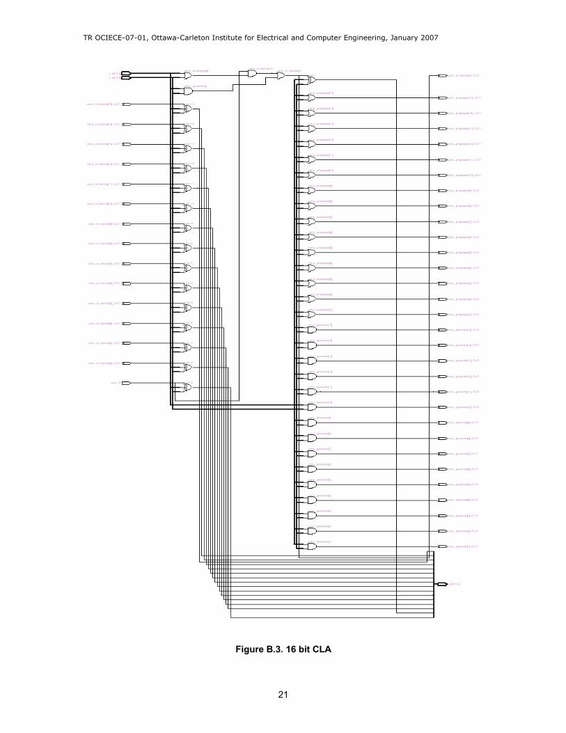
V. RESULTS
The ability of genVHDL to generate VHDL code is demonstrated using a use case and an example of a CLA (see APPENDEX ‘A’ for more details on CLA). The carry term for each stage has been recursively expanded. This allows to implement each individual stage of carry expression to be implemented as two-level AND-OR gates. It reduces the carry signal propagation delay (a limiting factor when ripple carry adder is used). In this way we get a high performance circuit for addition. The generated VHDL for CLA has been synthesized using Quartus II IDE (integrated development environment) from Altera. Register transfer level (RTL) view of
architectures and timing waveforms of 4 and 16 bit CLA are shown in APPENDEX ‘B’.
An example XML file containing 3 library components is shown in figure 4. These library components are 8 bit 8x1 multiplexer, 8 bit CLA and 16 bit CLA and the code generated for them is also shown in 3 different lists.
VI. COMPARISON WITH HAND CODED HDL
To compare synthesis of our generated code in VHDL, we have compared it with a hand written code in Verilog for 8 bit CLA. The Architecture and timing Waveforms are shown in figure 5 and figure 6 for hand written code (Verilog) for 8 bit CLA.
Figure 5 (a). 8 bit CLA (hand implemented in Verilog)
12

TR OCIECE-07-01, Ottawa-Carleton Institute for Electrical and Computer Engineering, January 2007
Figure 5 (b). Expansion of 4 bit CLA (hand implemented in Verilog) block used in (b)
Figure 6. 8 bit CLA (hand implemented in Verilog) Timing Waveforms
13

TR OCIECE-07-01, Ottawa-Carleton Institute for Electrical and Computer Engineering, January 2007
Figure 7. 8 bit CLA (genVHDL)
14

TR OCIECE-07-01, Ottawa-Carleton Institute for Electrical and Computer Engineering, January 2007
The Architecture and timing Waveforms are shown in figure 7 and figure 8 for generated code (VHDL) by genVHDL for 8 bit CLA. If we compare the timing waveforms of both the circuits, we don’t find any difference. That tells us that there is no difference in the output of both the circuits. However there is a difference in the architecture of both the circuits. There is a difference in the number of gates used and wires. Although we could have compared that with the power used in he circuit. But this is out of scope of this report.
Figure 8. 8 bit CLA (genVHDL) Timing Waveforms
VII. CONCLUSION AND FUTURE RESEARCH
We have demonstrated that XML which is an open source and universally accepted standard can be used to describe hardware specifications at a higher level, to make it as compact as possible and easy for different design teams to exchange and share design data. The tool genVHDL has been used to generate code from XML for different digital logic components. As an example and a use case the code for CLA has been generated using genVHDL and synthesized using Altera Quartus II IDE.
15

TR OCIECE-07-01, Ottawa-Carleton Institute for Electrical and Computer Engineering, January 2007
AST is used as an intermediate representation in the tool. So in the future this tool can be
extended for generating code from a grammar defined in XML. This grammar can be used to optimize the code generation for different languages. Different rules and actions can be defined
using this grammar, to accommodate an action semantic language, and let us change the behavior of the particular library component. This action language can also be used in combining different library components to generate code for much more complex circuits and chips.
7.1. Future extensionsFuture extensions for the tool can be summarized as follows:
i. This tool can be extended to include code generation for other languages.ii. A language grammar can be implemented using the AST as described above. iii. Database of library components can be created and can be used for building complex
chips and circuits.
Using extensions ii and iii complex circuits and chips can be designed. The block diagram in figure 9 gives an overview of some of the extensions listed above:
Figure 9. Future extensions to genVHDL
16

TR OCIECE-07-01, Ottawa-Carleton Institute for Electrical and Computer Engineering, January 2007
Because of the length of the source code a complete hard copy has not been included in this report. Appendix 'D' lists the source code for important header files. The source code and the documentation can be downloaded from the following URL:
http://chat.carleton.ca/~salam3/pub/genVHDL/tr.html
17

TR OCIECE-07-01, Ottawa-Carleton Institute for Electrical and Computer Engineering, January 2007
APPENDIX 'A'
CASE Study: Carry Look-Ahead Adder (CLA)
We chose CLA as an example application because it’s a very popular implementation of an adder which improves on ripple carry adder. It is also used as one of the important block in building commercial circuits. In ripple carry adder the carry ripples through the addition. As an example we can take a look at the following binary addition.
The carry ripples through the addition and we get it after 4th addition. In this way it creates logic gate delays, and is also called as propagation delay. To decrease the number of delays in this circuit a carry look-ahead adder is used. The carry is calculated in advance. This is how it works:
C1 = A0B0 + (A0 ⊕ B0)C0
We take Gi = AiBi
And
Pi = Ai ⊕ Bi
So putting these values in above equation we get:C1 = G0 + P0C0
SimilarlyC2 = G1 + P1C1
C2 = G1 + P1 (G0 + P0C0)C2 = G1 + P1G0 + P1P0C0
SimilarlyC3 = G2 + P2G1 + P2P1G0 + P2P1P0C0
C4 = G3 + P3G2 + P3P2G1 + P3P2P1G0 + P3P2P1P0C0 (1)
So to calculate the Pi we need an XOR gate and that’s two gate delays. There is a delay for an AND gate and another for OR gate. Total four gate delays.
18

TR OCIECE-07-01, Ottawa-Carleton Institute for Electrical and Computer Engineering, January 2007
To calculate the sum:
Si = Ai ⊕ Bi ⊕ Ci
So two additional gate delays for sum (XOR gate)
So now we have to generate Si, Pi and Gi. We can do that using partial full adders. The complete circuit for 4 bit CLA is shown in figure A.
Figure A. A simple 4 bit CLA
Similarly we can build CLA for 8, 16, 32 and 64 bits. As shown in APPENDEX ‘B’.
19

TR OCIECE-07-01, Ottawa-Carleton Institute for Electrical and Computer Engineering, January 2007
APPENDIX ‘B’
RTL view of Architectures and Timing Waveforms of 4 and 16 bit CLA
Figure B.1. 4 bit CLA
Figure B.2. 4 bit CLA Timing Waveforms
20
TR OCIECE-07-01, Ottawa-Carleton Institute for Electrical and Computer Engineering, January 2007
Figure B.3. 16 bit CLA
21

TR OCIECE-07-01, Ottawa-Carleton Institute for Electrical and Computer Engineering, January 2007
Figure B.4. 16 bit CLA Timing Waveforms
22

TR OCIECE-07-01, Ottawa-Carleton Institute for Electrical and Computer Engineering, January 2007
APPENDIX ‘C’
User Guide genVHDL
The tool genVHDL [16] generates VHDL code from higher level hardware specifications in XML. It's written in C++ and currently compiled for Windows platform. But it should be easily ported to other platforms.
a. Command line usage
genVHDL [options] <XML file> <VHDL file>
Options: -v=xxx Validation scheme [always | never | auto*] -o=xxx Name of VHDL file to be created [DCL.vhdl*] -? Show this help
* = Default if not provided explicitly.
Example of executing genVHDL with auto validation and sample.xml as input and sample.vhdl as output files:
genVHDL -o=sample.vhdl sample.xml
b. Example XML
An example XML file containing 3 library components and the code generated for them is shown
in Figure 4.
c. Future extensions
Future extensions for genVHDL are described in section VII.
23

TR OCIECE-07-01, Ottawa-Carleton Institute for Electrical and Computer Engineering, January 2007
APPENDIX 'D'
/*---------------------------------------------------------------------|| Filename: gencode.h| Dated: 26 February, 2006| By: Shahid Alam ([email protected])|| Description: Header file for to be included in genCodeVHDL and AST|| TO DO: | ---------------------------------------------------------------------*/
#ifndef _GENCODE_H_#define _GENCODE_H_
#include "global.h"
/**** Function defined in genCodeVHDL.cpp to be linked in the Symbol / Hash Table* for creating actions to generate VHDL code for OR gate**/const void genEntityOR (unsigned int numberOfDataInput, unsigned int notUsed);
/**** Function defined in genCodeVHDL.cpp to be linked in the Symbol / Hash Table* for creating actions to generate VHDL code for AND gate**/const void genEntityAND (unsigned int numberOfDataInput, unsigned int notUsed);
/**** Function defined in genCodeVHDL.cpp to be linked in the Symbol / Hash Table* for creating actions to generate VHDL code for NAND gate**/const void genEntityNAND (unsigned int numberOfDataInput, unsigned int notUsed);
/**** Function defined in genCodeVHDL.cpp to be linked in the Symbol / Hash Table* for creating actions to generate VHDL code for XOR gate**/const void genEntityXOR (unsigned int numberOfDataInput, unsigned int notUsed);
/**** Function defined in genCodeVHDL.cpp to be linked in the Symbol / Hash Table* for creating actions to generate VHDL code for MULTIPLEXER**/const void genEntityMUX (unsigned int numberOfDataInput, unsigned int widthOfDataInput);
24

TR OCIECE-07-01, Ottawa-Carleton Institute for Electrical and Computer Engineering, January 2007
/**** Function defined in genCodeVHDL.cpp to be linked in the Symbol / Hash Table* for creating actions to generate VHDL code for CARRY LOOK AHEAD ADDER**/const void genEntityCLA (unsigned int widthOfDataInput, unsigned int notUsed);
/**** Pointer listed as array in the symbol / hash table.* Points to functions above defined in genCodeVHDL.cpp**/typedef const void (*tLinkSymTable) (unsigned int, unsigned int);
/**** Copy 'src' String to 'tgt' String including 'from' and 'to' as starting and ending indices* @param src source string to be copied from* @param from position in the src string to start from* @param to end position in the src string to finish to* @param tgt target string to be copied to**/int copyStringToString (const char *src, int from, int to, char *tgt);
#endif // _GENCODE_H_
/*----------------------------------------------------------------------|| Filename: ast.h| Dated: 26 February, 2006| By: Shahid Alam ([email protected])|| Description: Header file for AST class to be included in AST and processXML|| TO DO: | ---------------------------------------------------------------------*/
#ifndef _AST_H_#define _AST_H_
#include "global.h"#include "list.h"#include "symtable.h"
namespace khudi{
/**** This is the intermediate representation during translation * from XML to the specified language in the form of an * Abstract Syntax Tree (AST). It's a linked list of XML * structure. It contains a copy of XML with annotation i.e a * link to a symbol table for actions to create code for * specified component in a particular language. * If traversed from bottom to top, and using the symbol table, * it produces the source code for the specified * language (VHDL / Verilog).
25

TR OCIECE-07-01, Ottawa-Carleton Institute for Electrical and Computer Engineering, January 2007
**/class AST : public List{public:
/**** Constructor**/AST ();/**** Destructor**/~AST ();/**** Create and insert OR node into AST* @param numberOfDataInput number of data input to the OR gate**/void insertOR (unsigned int numberOfDataInput);/**** Create and insert AND node into AST* @param numberOfDataInput number of data input to the AND gate**/void insertAND (unsigned int numberOfDataInput);/**** Create and insert NAND node into AST* @param numberOfDataInput number of data input to the NAND gate**/void insertNAND (unsigned int numberOfDataInput);/**** Create and insert XOR node into AST* @param numberOfDataInput number of data input to the XOR gate**/void insertXOR (unsigned int numberOfDataInput);/**** Create and insert MUX node into AST* @param numberOfDataInput number of data input to the MUX gate* @param widthOfDataInput width of data input to the MUX gate**/void insertMUX (unsigned int numberOfDataInput, unsigned int
widthOfDataInput);/**** Create and insert CLA node into AST* @param numberOfDataInput number of data input to the MUX gate**/void insertCLA (unsigned int widthOfDataInput);/**** Print AST for debugging**/void print (void);
26

TR OCIECE-07-01, Ottawa-Carleton Institute for Electrical and Computer Engineering, January 2007
/**** Returns a pointer to the first node.**/const char * getFirstNode (void);/**** Returns a pointer to the nex node.**/const char * getNextNode(void);
private:List list;void * nPtr;
symTable *symT;
OR *or;AND *and;NAND *nand;XOR *xor;MUX *mux;CLA *cla;
void printTableIndex (long int index);};
}
#endif // _AST_H_
/*----------------------------------------------------------------------|| Filename: symtable.h| Dated: 26 February, 2006| By: Shahid Alam ([email protected])|| Description: Header file for symtable.cpp|| TO DO: | ---------------------------------------------------------------------*/
#ifndef _SYMTABLE_H_#define _SYMTABLE_H_
#include "global.h"#include "gencode.h"#include "xmlstruct.h"
namespace khudi{
/**** It's a simple hash table for storing all the Nodes defined in XML * Schema. Symbol Table is a static list of components with a link to the * action function. Since we already know the number of components * so it was decided to keep this static. Advantage is that searching * is O(1) complex. It also doesn't take as much space as the number of * components. Currently only one action is added that creates the * structure and behavior of the digital component, which is already * defined. So it doesn't give flexibility to the user to change the
27

TR OCIECE-07-01, Ottawa-Carleton Institute for Electrical and Computer Engineering, January 2007
* behavior,in the XML. Latter this facility can be added in the form of * an Action Language, based on Action Semantics.**/class symTable{public:
/**** Constructor. It creates all the links to the action functions * defined in gencode.h**/symTable ();/**** Destructor**/~symTable ();/**** Searches the link to the action function for particular Node * from the table in constant O(1) time.* @param nodeIndex index / hash of the Node stored in the table.**/tLinkSymTable getActionLink (long int nodeIndex);/**** Prints the action function for particular Node for debugging* @param index index / hash of the Node stored in the table.**/const void printSymbol (long int index);/**** Prints the complete symbol table for debugging**/const void print (void);
private:/**** Declaration of the hash table for storing all the Nodes * defined in XML Schema with a link to the action function * for that particular Node.**/typedef struct stable{
tLinkSymTable action;} Table;Table table[MAX_NUMBER_NODES];
};}
#endif // _SYMTABLE_H_
28

TR OCIECE-07-01, Ottawa-Carleton Institute for Electrical and Computer Engineering, January 2007
/*----------------------------------------------------------------------|| Filename: list.h| Dated: 26 February, 2006| By: Shahid Alam ([email protected])|| Description: Header for Link List class in list.cpp|| TO DO: | ---------------------------------------------------------------------*/
#ifndef _LIST_H_#define _LIST_H_
#include "global.h"
namespace khudi{
/**** Class ListNode. Data structure for a Node in the List.**/class ListNode{
/**** Data Pointer points to the data stored in the list. It can be * be any data structure. But then handling of data structure is * the responsibility of the caller.**/const char *dataPtr;/**** Next and Previous pointers**/ListNode *nextptr, *prevptr;
public:/**** Constructor* @param dPtr data pointer points to the data stored in the Node* @see dataPtr**/ListNode (const char *dPtr){
dataPtr = dPtr;nextptr = 0;
};
/**** Sets the pointer to the next Node.* @param ptr pointer to the Node in the List* @see ListNode**/void setNextPtr (ListNode *ptr) {
nextptr = ptr;return;
};
29

TR OCIECE-07-01, Ottawa-Carleton Institute for Electrical and Computer Engineering, January 2007
/**** Gets the next pointer of the Node* @return pointer to ListNode* @see ListNode**/ListNode* getNextPtr () const{
return nextptr;};
/**** Sets the previous pointer of the Node.* @param ptr pointer to the ListNode* @see ListNode**/void setPrevPtr (ListNode *ptr) {
prevptr = ptr;return;
};
/**** Gets the previous pointer of the Node.* @return pointer to ListNode* @see ListNode**/ListNode* getPrevPtr () const{
return prevptr;};
/**** Gets the value of the data.* @return pointer to data linked in the List* @see dataPtr**/const char * getDataPtr () const{
return dataPtr;};
};
/**** Class List. Implements a linked list**/class List{
/**** pointers for first and last Node in the List.* @see ListNode**/ListNode *firstptr, *lastptr;/***
30

TR OCIECE-07-01, Ottawa-Carleton Institute for Electrical and Computer Engineering, January 2007
* Dynamically allocates memory for the new Node.* @param dPtr data pointer points to the data stored in the Node* @see dataPtr**/ListNode *getNewNode (const char *dPtr);
public:/**** Constructor**/List ();/**** Destructor**/~List ();/*****/const char * getData (void *nPtr);/**** Returns first pointer* @return void pointer*/void * getFirst (void);/**** Returns next pointer* @param cPtr current pointer to the Node**/void * getNext (void * cPtr);/**** Appends a List. If it is empty new Node will be added * and the pointer of the Node will be assigned to first else * it will be assigned to last and the previous last pointer's * next pointer will be set to the newptr.* @param dPtr data pointer points to the data stored in the Node* @see ListNode::dataPtr**/void append (const char *dPtr);/**** Removes the last Node of the list. It starts with the * firstptr then reach to the lastptr keeping track of the * previous pointer because then that becomes the lastptr * when lastptr is removed.**/void removeLast (void);/**** It counts the number of Nodes in the List by counting * the linking pointers of the List using getNextPtr () * function.* @return the number of nodes in the List**/long int count (void) const;
31

TR OCIECE-07-01, Ottawa-Carleton Institute for Electrical and Computer Engineering, January 2007
/**** It adds a Node with a value(val) at the given position(posn). * If the user gives the position as -1 it will however add the * Node but with a warning. Position '0' is for first Node.* @param dPtr data pointer points to the data stored in the Node* @see ListNode::dataPtr* @param posn position in the List where a new Node will added**/void addN (const char *dPtr, long int posn);/**** Prints the List for debugging. CALLBACK the function passed* to it to let the caller print the data. Because data can have* different strucure. And it should be handled by the caller.* @see ListNode::dataPtr* @param fPtr function pointer passed to be called while * traversing the list. Function has one input parameter which * points to the data stored in the List.**/void print (void(*fPtr)(const char *)) const;
/**** Check if List is empty or not* @return 0 if List is empty**/int isempty (void) const{
return firstptr == 0;};
};
}
#endif // _LIST_H_
32

TR OCIECE-07-01, Ottawa-Carleton Institute for Electrical and Computer Engineering, January 2007
ACKNOWLEDGMENTS
I thank for the support of Professor Misbah Islam of School of Information Technology and Engineering at University of Ottawa in encouraging and guiding me in the development of this tool, and writing of this report. Without his support this wouldn't have been possible. I would also like to thank my wife and four lovely kids for giving me their support by providing me all the time to work on this research project and the report.
33

TR OCIECE-07-01, Ottawa-Carleton Institute for Electrical and Computer Engineering, January 2007
REFERENCES
[1] Alfred V. Aho, Ravi Sethi and Jeffrey D. Ullman, “Compilers principles, techniques and tools”, published by Addison –Wesley © 1986.
[2] Chaudhary, V.; Francis, M.; Xiaoling Huang; Mantooth, H.A.; Paragon-a mixed-signal behavioral modeling environment; International Conference on Communications, Circuits and Systems and West Sino Expositions, IEEE © 2002 Volume 2, 29 June-1 July 2002 Page(s):1315 - 1321 vol.2.
[3] Fuji, N. (Graduate School of Computer Science., Hosei., Japan;); Yukita, S.; Koike, N.; Kunli, T.L. “Top-down eLearning tools for hardware logic design” Proceedings. 2003 International Conference on Cyberworlds, © 2003, p 410-17.
[4] Seng, S.P. (Imperial Coolege. Of Science. Technological. & Medical., London, UK;); palem, K.V.; Rabbah, R.M.; Wong, W.F.; Luk, W.; Cheung, P.Y.K. “PD-XML: extensible markup language for processor description”, 2002 IEE International Conference on Field-Programmable Technology (FPT). Proceedings (Cat. No.02EX603), © 2002, p 437-40.
[5] Karayiannis, T. (York Univ., UK;); Mades, J.; Schneider, T.; Windisch, A.; Ecker, W. “Using XML for representation and visualization of elaborated VHDL-AMS models”, Proceedings VHDL International Users Forum Fall Workshop, 2000, p 83-7.
[6] Extensible Markup Language (XML); http://www.w3.org/XML
[7] HDML: compiled VHDL in XML, Reshadi, M.H.; Goji-Ara, B.; Navabi, Z.; VHDL International Users Forum Fall Workshop, 2000. Proceedings 18-20 Oct. 2000 Page(s):69 – 74.
[8] Xerces-C++ a validating XML parser; http://xml.apache.org/xerces-c
[9] W3C Document Object Model (DOM); http://www.w3.org/DOM
[10] Simple API for XML (SAX); http://www.saxproject.org
[11] Standard Generalized Markup Language (SGML); http://www.w3.org/MarkUp/SGML
[12] Yuri Chernukhin, Maxim Polanov, Chandrasekhar Vemulally, Eugene Solodovnik, H. Alan mantooth and Roger Dougal, “Deploying Modelica Models into Multiple Simulation Environments”, Proceeding of the 2005 IEEE International Behavioral Modeling and Simulation Workshop (IEEE Cat No.05 8833) © 2005.
[13] Extensible Style Sheet Transformations (XSLT); http://www.w3.org/TR/xslt
[14] XML Path Language; http://www.w3.org/TR/xpath [15] Anneke Kleppe, Wim Bast, Jos B Warmer “MDA Explained, the Model Driven Architecture: The Model Driven Architecture: Practice and Promise” ISBN: 032119442X © Addison-Wesley Professional 2003.
34