Generic Mechanical Design Criteria for PWR Fuel Designs · Generic Mechanical Design Criteria for...
139
SIEMENS L L EMF-92-116(NP)(A) Revision 0 Siemens Power Corporation Nuclear Division Generic Mechanical Design Criteria for PWR Fuel Designs February 1999
Transcript of Generic Mechanical Design Criteria for PWR Fuel Designs · Generic Mechanical Design Criteria for...

SIEMENS
L L
EMF-92-116(NP)(A) Revision 0
Siemens Power Corporation
Nuclear Division
Generic Mechanical Design Criteria for PWR Fuel Designs
February 1999
SIEMENS ISSUED IN SPC ON-LINE DOCUMENT SYSTEM DATE: 17,0a 0
Issue Date:
Generic Mechanical Design Criteria for PWR Fuel Designs
Prepared by:
~Z9~k4 4L 7-2t-y12 R. A. Copeland, Manager
Reload Ucensing Technical Projects
R. J. DeSteese, Project Engineer PWR Design Fuel Design
July 1992
EMF-92-116
Imah
4
U.S. Nuclear Regulatory Commission 4 Report Disclaimer
Important Notice Regarding the Contents and Use of This Document
Please Read Carefully
This technical report was derived through research and development programs sponsored by Siemens Power Corporation. It is being submitted by Siemens Power Corporation to the U.S. Nuclear Regulatory Commission as part of a technical contribution to facilitate safety analyses by licensees of the U.S. Nuclear Regulatory Commission which utilize Siemne•nPower Corporation fabricated reload fuel or technical servic•sp-rovided by Siemens Power Corporation for light water power reactors and it is true and correct to the best of Siemens Power Corporation's knowledge, information, and belief. The information contained herein may be used by the U.S. Nuclear Regulatory Commission in its review of this report and, under the terms of the respective agreements, by licensees or applicants before the U.S. Nuclear Regulatory Commission which are customers of Siemens Power Corporation in their demonstration of compliance with the U.S. Nuclear Regulatory Commission's regulations.
Siemens Power Corporation's warranties and representations concerning the subject matter of this document are those set forth in the agreement between Siemens Power Corporation and the Customer pursuant to which this document is issued. Accordingly, except as otherwise expressly provided in such agreement, neither Siemens Power Corporation nor any person acting on its behalf:
a. makes any warranty, or representation, express or implied, with respect to the accuracy, completeness, or usefulness of the information contained in this document, or that the use of any information, apparatus, method, or process disclosed in this document will not infringe privately owned rights;
or
b. assumes any liabilities with respect to the use of, or for damages resulting from the use of, any information, apparatus, method, or process disclosed in this document.
A•
UNITED STATES NUCLEAR REGULATORY COMMISSION
WASHINGTON, D.C. 20o8800
February 2, 1999
Mr.. James F. Mallay, Director Regulatory Affairs . ~ r Siemens Power Corporation 2101 Horn Rapids Road P. O. Box 130 Richland, WA 99352-0130
SUBJECT: ACCEPTANCE FOR REFERENCING OF SIEMENS POWER CORPORATION TOPICAL REPORT EMF-92-116(P): "GENERIC MECHANICAL DESIGN CRITERIA FOR PWR FUEL DESIGNS," (TAC NO. M84245)
Dear Mr. Mallay:
The staff has reviewed the subject report submitted by Siemens Power Corporation (SPC) by letter of August 3, 1992, and your responses dated June 29, August 23, and November 16, 1994, January 31 and October 12, 1995, June 30, 1997, and January 14, 1998, to our requests for additional information. On the basis of our review, the staff has found the subject report to be acceptable for referencing in license applications to the extent specified and under the limitations stated in the enclosed report and U.S. Nuclear Regulatory Commission (NRC) technical evaluation. The evaluation defines the basis for acceptance of the report.
The staff will not repeat its review of the matters described in SPC Topical Report EMF-92-116(P) and found acceptable when the report appears as a reference in license applications, except to ensure that the material presented applies to the specific plant involved. NRC acceptance applies only to the matters described in SPC Topical Report EMF-92-116(P). In accordance with procedures established in NUREG-0390, the NRC requests that SPC publish accepted versions of the report, proprietary and non-proprietary, within 3 months of receipt of this letter. The accepted versions shall incorporate this letter and the enclosed evaluation between the title page and the abstract and an -A (designating accepted) following the report identification symbol.
Should our acceptance criteria or regulations change so that our conclusions as to the acceptability of the report are no longer valid, applicants referencing this topical report will be expected to revise and resubmit their respective documentation, or submit justification for the continued applicability of the topical report without revision of their respective documentation.
Sin rely,
n-~i Akst '~icz. Actin g Chief' Generic Issues and Environmenta-tfojects Branch Division of Reactor Program Management Office of Nuclear Reactor Regulation
Enclosures: SPC Topical Report EMF-92-1 16(P) Safety Evaluation
UNITED STATES NUCLEAR REGULATORY COMMISSION
WASHINGTON. D.C. 20555-001
ENCLOSURE 1
SAFETY EVALUATION OF SIEMENS POWER CORPORATION TOPICAL REPORT EMF-92-116(P)
"GENERIC MECHANICAL DESIGN CRITERIA FOR PWR FUEL DESIGNS"
I INTRODUCTION
In a letter dated August 3, 1992, from D. E. Hershberger, Siemens Power Corporation (SPC), to the U.S. Nuclear Regulatory Commission (NRC), SPC submitted a Topical Report EMF-92-116(P), "Generic Mechanical Design Criteria for PWR Fuel Designs," for NRC review. EMF-92-116(P) describes an approach to fuel mechanical design criteria that SPC intends to apply to changes or improvements in existing fuel designs for pressurized-water reactor (PWR) fuel. This approach will not require the staff review and prior approval when these criteria are met. This approach Is consistent with the staff position on other fuel vendors.
The NRC staff was supported in this review by its consultant, Pacific Northwest National Laboratory (PNNL). Our consultant's technical evaluation report (TER), which is attached, provides technical findings relative to its review.
2 EVALUATION
The staff has reviewed the enclosed TER, and concludes that the TER provides an adequate technical basis to approve EMF-92-116(P), except for Section 3.2, Violent Expulsion of Fuel. With regard to Section 3.2, the staff believes that additional clarification is necessary with respect to the acceptance criteria in Regulatory Guide 1.77 and Standard Review Plan 4.2 for the rod ejection accidents. These acceptance criteria are considered nonconservative in light of some test data from foreign test reactors on reactivity-initiated accidents. However, the staff considers the fuel to be acceptable to a rod-average bumup level of 62 GWd/MTU bumup because the probability of these accidents is low and generic plant transient calculations indicate that energy inputs during these transients are low and will remain below the relevant test data failure levels. This position is consistent with the Agency Program Plan for HighBumup Fuel and the memorandum from L. Callan to the Commissioners dated July 15, 1997.
With this clarification, the staff agrees with PNNL's conclusion that the fuel mechanical design criteria described in EMF-92-116(P) are acceptable for PWR licensing applications. Based on our review, the staff adopts the findings in the attached TER.
3 CONCLUSIONS
The staff has reviewed the SPC's PWR fuel mechanical design criteria described in EMF-92-116(P), and finds that the design criteria are acceptable for PWR licensing applications up to 62,000 MWd/MTU rod average bumup.

2
For each application of the mechanical design criteria, SPC must document the design evaluation process demonstrating conformance to these criteria and submit a summary of the evaluation to the NRC staff for possible use in an audit to confirm that SPC is in compliance with these design criteria.
,!
;V
uq
TECHNICAL EVALUATION REPORT OF THE TOPICAL REPORT EMF-92-116(P), "GENERIC MECHANICAL DESIGN CRITERIA FOR PWR FUEL DESIGNS"
C. E. Beyer
September 1998
Prepared for Reactor Systems Branch Office of Nuclear Reactor Regulation U.S. Nuclear Regulatory Commission under contract DE-AC06-76RLO 1830 NRC FIN 12009
Pacific Northwest National Laboratory Richland, Washington 99352
1.0 INTRODUCTION ...................................................... 1.1
2.0 THERMAL-MECHANICAL DESIGN CRITERIA ................. ....... 2.1 2.1 DESIGN STRESS LIMITS ....................................... 2.1 2.2 CLADDING DESIGN STRAIN LIMITS ............................ 2.1 2.3 CLADDING STRAIN FATIGUE .................................. 2.2 2.4 FRETTING WEAR ............................................. 2.3 2.5 OXIDATION, HYDRIDING, AND CRUD BUILDUP ................. 2.3 2.6 AXIAL IRRADIATION GROWTH ................................ 2.5 2.7 ROD INTERNAL PRESSURE .................................... 2.6 2.8 ASSEMBLY LIFTOFF .......................................... 2.6 2.9 FUEL ASSEMBLY HANDLING .................................. 2.7 2.10 INTERNAL HYDRIDING ....................................... 2.7 2.11 CLADDING COLLAPSE ........................................ 2.8 2.12 OVERHEATING OF FUEL PELLETS .............................. 2.8 2.13 PELLET/CLADDING INTERACTION ............................. 2.9 2.14 FUEL ROD MECHANICAL FRACTURING ........................ 2.9 2.15 ROD BOWING ............................................... 2.10 2.16 FUEL DENSIFICATION AND SWELLING ........................ 2.11
3.0 FUEL COOLABILITY .......................................... 3.1 3.1 CLADDING EMBRITTLEMENT ................................. 3.1 3.2 VIOLENT EXPULSION OF FUEL ................................ 3.1 3.3 CLADDING RUPTURE ......................................... 3.2
4.0 THERMAL AND HYDRAULIC DESIGN CRITERIA ......................... 4.1 4.1 HYDRAULIC COMPATIBILITY ................................. 4.1 4.2 THERMAL MARGIN PERFORMANCE ............................ 4.2 4.3 FUEL MELTING ............................................... 4.3 4.4 ROD BOW ING ................................................ 4.3
5.0 NUCLEAR DESIGN ANALYSIS .......................................... 5.1 5.1 POWER AND EXPOSURE HISTORIES ............................ 5.1 5.2 KINETIC PARAMETERS ....................................... 5.1 5.3 CONTROL ROD REACTIVITY .................................. 5.1
6.0 TESTING, INSPECTION AND SURVEILLANCE ............................ 6.1
7.0 CONCLUSIONS ....................................................... 7.1
8.0 REFERENCES ........................................................ 8.1
LIST OF ACRONYMS
AO0 Anticipated Operational Occurrence
CFR Code of Federal Regulations
DNB Departure From Nucleate Boiling
DNBR Departure From Nucleate Boiling Ratio
EOL End of Life
ECCS Emergency Core Cooling System
GDC General Design Criterion
LFA Lead Fuel Assembly
LOCA Loss-of-Coolant Accident
NRC Nuclear Regulatory Commission
PWR Pressurized Water Reactor
PNNL Pacific Northwest National Laboratory
PCT Peak Cladding Temperature
RIA Reactivity Initiated Accident
SAFDL Specified Acceptable Fuel Design Limits
SPC Siemens Power Corporation
SRP Standard Review Plan
1.0 RIIRODUCTION
In order to support customer needs and remain competitive, the fuel vendors are continually improving their fuel designs. Generally, the changes in design are made with approved methodologies. The regulatory procedures to qualify and approve the new designs are standard. However, the review and approval of these new designs place a burden on the staff resources.
Recently, the U.S. Nuclear Regulatory Commission (NRC) staff proposed that a set of acceptance criteria, to be satisfied by new fuel designs, be established for each fuel vendor. Once the acceptance criteria are approved, fuel designs or changes satisfying the criteria would not require explicit staff review. Satisfaction of the acceptance criteria would be sufficient for approval by reference to the acceptance criteria. Also, the NRC staff requires that the acceptance criteria be nonproprietary so that any interested party will have access to the acceptance criteria. The objective of this approach is to expedite the review process and reduce the staff and industry resources needed for review of new fuel designs.
In response to the NRC staffs proposal, the Siemens Power Corporation (SPC) has submitted to the NRC a topical report, entitled "Generic Mechanical Design Criteria for PWR Fuel Designs" for review and approval (Reference 1). Described in this report are the process and criteria that SPC intends to apply to minor changes in existing PWR fuel designs that will not require NRC review and approval as long as these criteria are satisfied. SPC intends to apply these criteria to all of their current PWR fuel designs. The SPC analysis methodologies that are used for determining that the specific fuel licensing criteria are satisfied have in most cases been identified and previously approved by the NRC and, therefore, these previously approved criteria have not been reviewed in detail during this review, but discussed briefly and verified that they are generically applicable to future design changes. Those that have not been previously reviewed were reviewed and will be discussed in much greater detail. Most of the SPC analysis methodologies are generic but there are some that can be design specific depending on the design change. The analysis methodologies that can be design specific will be discussed in more detail as to when analysis methods need to be altered and when NRC review is required.
Pacific Northwest National Laboratory (PNNL) has acted as a consultant to the NRC in this review. As a result of the NRC staff and their PNNL consultant's review of this topical report, a list of questions were sent by the NRC to SPC requesting clarification of specific licensing criteria and licensing analyses (Reference 2). SPC responded to the questions in Reference 3. SPC supplied further information in Reference 4 on criteria for changes in the coefficients of the PWR rod and assembly growth correlations which is discussed in Section 2.6 of this report. Following discussions with SPC staff, a further response was transmitted to NRC (Reference 5) that provided more detailed information in response to the original NRC questions (Reference 2).
1.1
A request was made to SPC for further information on 1) when changes can be made to SPC axial growth model without NRC review and the determination of the upper bound growth prediction, 2) why is it not necessary for SPC to test for flow induced vibration for each new design particularly since SPC has seen fretting failures in Palisades due to vibration, 3) providing corrosion data from high coolant outlet temperature plants, and 4) how does SPC determine when a design change requires a new DNB correlation.' SPC responded to this request in Reference 6. SPC provided additional information in Reference 7 on the limitations to changes to the SPC fuel rod axial growth model without the need for NRC review. SPC also provided additional high bumup corrosion data in Reference 8 including a plant with high coolant outlet temperatures as requested in Reference 2. As a result of PNNL's review of this data SPC altered their corrosion model to provide a higher corrosion rate when corrosion exceeded a given level and presented additional corrosion data from a high coolant temperature plant with rod-average burnups up to 63.4 GWd/MTU. This information was transmitted in " Reference 9.
This review of topical report EMF-92-116 was based on those licensing requirements identified in Section 4.2 of the Standard Review Plan (SRP) (Reference 10). The objectives of this review of fuel licensing criteria, as described in Section 4.2 of the SRP, are to provide assurance that 1) the fuel system is not damaged as a result of normal operation and anticipated operational occurrences (AOOs); 2) the fuel system damage is never so severe as to prevent control rod insertion when it is required; 3) the number of fuel rod failures is not underestimated for postulated accidents; and 4) the coolability is always maintained. A "not damaged" fuel system is defined as fuel rods that do not fail, fuel system dimensions that remain within operational tolerances, and functional capabilities that are not reduced below those assumed in the safety analyses. Objective 1, above, is consistent with General Design Criterion (GDC) 10 (10 Code of Federal Regulations (CFR) 50, Appendix A] (Reference 11), and the design limits that accomplish this are called specified acceptable fuel design limits (SAFDLs). "Fuel rod failure" means that the fuel rod leaks and that the first fission product barrier (the cladding) has, therefore, been breached. Fuel rod failures must be accounted for in the dose analysis required by 10 CFR 100 (Reference 12) for postulated accidents. "Coolability," which is sometimes termed "coolable geometry," means, in general, that the fuel assembly retains its rod-bundle geometrical configuration with adequate coolant channels to j permit removal of residual heat even after a severe accident. The general requirements to maintain control rod insertability and core coolability appear repeatedly in the GDC (e.g., GDC 27 and 35). Specific coolability requirements for the loss-of-coolant accident (LOCA) are given in 10 CFR 50, Section 50.46 (Reference 13).
The proposed SPC PWR licensing criteria address thermal-mechanical, thermal-hydraulic, accident analysis, and nuclear licensing criteria including power history selection criteria for specific design calculations. Within the discussions of these licensing criteria a brief discussion of the NRC approved analysis methods used by SPC is provided. However, these methods are not reviewed unless otherwise noted. The exception to this is when an analysis methodology is design specific. In this situation the discussion will identify;
1.2

1) when an analysis methodology needs to be altered due to a design change and, 2) whether the altered analysis methodology needs to be submitted and reviewed by the NRC. If no discussion is provided, it should be assumed that changes to an analysis methodology need to be submitted to NRC for review. In addition, SPC addresses testing inspection and surveillance requirements to further verify conformance to the licensing criteria.
The purpose of the PWR licensing criteria or limits are to provide limiting values that prevent fuel damage or failure with respect to each damage mechanism. Reviewed in this report is the applicability of the SPC PWR licensing criteria/limits to the SPC fuel designs up to currently approved burnup levels. These approved licensing criteria/limits, along with certain definitions for fuel failure, constitute the SAFDLs required by GDC 10.
1.3
2.0 THERMAL-MECHANICAL DESIGN CRITERI
' The licensing criteria presented in this section should not be exceeded during normal operation and AQOs. The evaluation portion of each damage mechanism evaluates the analysis methods and analyses used by SPC to demonstrate that the licensing criteria are not exceeded during normal operation including AQOs for SPC PWR designs.
2.1 DESIGN STRESS LIMITS
Srk - The SPC licensing basis for fuel assembly, fuel rod, burnable poison rod, and upper end fitting spring stresses is that the fuel system will be functional and will not be damaged due to excessive stresses. The licensing limits for fuel rod cladding stress under normal operation and AQOs are derived from the ASME Boiler Code, Section III, Article 111-2000 (Reference 14); and the specified 0.2% offset yield strength and ultimate strength for Zircaloy as provided in Table 3.1 of Reference 1. The stress categories include primary membrane and bending stresses, and the secondary stresses. Stress limits for normal operation and AQO events for assembly components also use the ASME Boiler and Pressure Vessel Code, Section III as a general guide. Stress limits for postulated accidents for the assembly components use the methods outlined in Appendix F of the ASME Boiler and Pressure Vessel Code, Section II. These criteria have been previously approved by the NRC (Reference 15 and 16) and continue to be applicable to SPC PWR designs up to a rod-average burnup level of 62 GWd/MTU.
E t - The SPC stress calculations use conventional open literature equations and finite element stress analysis codes such as ANSYS (Reference 17). These analysis methods have been previously approved by the NRC and continue to be applicable to SPC PWR designs. PNNL concludes that these analysis methods remain applicable for SPC PWR designs up to a rod-average bumup level of 62 GWd/MTU.
2.2 CLADDING DESIGN STRAIN LIMITS
Bases/Criteria - The SPC licensing basis for fuel rod cladding strain is that the fuel system will not be damaged due to excessive cladding strain. In order to meet this basis, the SPC design limit for cladding strain during steady-state operation and AOOs is that the cladding will not exceed 1% uniform strain (elastic + plastic) up to peak rod exposures of 60 GWd/MTU and a lower proprietary limit for peak exposures above 60 GWd/MTU. The former strain limit is the same limit that is used in Section 4.2 of the SRP and the latter is more conservative. Both of these limits have been previously approved for SPC PWR fuel designs (References 15 and 16). However, recently NRC has instituted a research program to examine the observed decrease in cladding ductility, i.e., less than 1% uniform strain capability, when the cladding has corrosion thicknesses above 100 pm and high bumup (References 18, 19, 20 and 21); however, this program has not been completed. The NRC has some concerns about cladding ductility but is waiting for the conclusions of the research program before
2.1
implementing any further ductility requirements on a generic basis. Therefore, PNNL concludes that the SPC licensing basis and strain limits are applicable for SPC PWR designs up to a rod-average bumup level of 62 GWd/MTU.
a - SPC utilizes two fuel performance codes for calculating cladding strain. The steady state RODEX2 fuel performance code (Reference 22) is used for normal operation and the RAMPEX code (Reference 23) is used for calculating cladding strain during transient events. Previous SPC PWR design approvals (References 15 and 16) have been based on cladding strain analyses using these codes. PNNL concludes that these codes remain acceptable for evaluating cladding strains for SPC PWR designs up to a rod-average bumup level of 62 GWd/MTU.
2.3 CLADDING STRAIN FATIGUE,
Bases/Criteria - The SPC criterion for strain fatigue limits the "total fatigue usage factor" to a conservative value less than one, where the fatigue usage factor is the number of expected power cycles during each duty cycle divided by the number of allowed cycles. The "total fatigue usage factor" is the sum of the individual usage factors for each duty cycle. Ther O'Donnell and Langer fatigue curves (Reference 24) are used to determine the number of allowed cycles for each stress amplitude. SPC further incorporates the NRC recommended (Reference 6) factor of 2 on stress amplitude or the factor of 20 on the number of cycles, whichever is more conservative. For the SPC analysis approach, the factor of 20 represents a reduction of 20 in the number of allowed cycles. This criterion is consistent with that in 3 Section 4.2 of the SRP and has previously been approved for SPC PWR fuel designs (References 15 and 16). PNNL concludes that this criterion remains applicable for SPC PWR designs up to a rod-average burnup level of 62 GWd/MTU.
Evaluation - The SPC analysis methodology for determining stress amplitude is based on the use of the RODEX2 code (Reference 22) and the RAMPEX code (Reference 23) along with the O'Donnell and Langer fatigue curve (Reference 24). The RODEX2 code provides initial steady state conditions while the RAMPEX code provides stress amplitude for the power cycles. This analysis methodology has been approved for SPC fuel designs. SPC was questioned (Reference 2) on why they do not include the effects of wall thinning due to cladding oxidation. SPC responded that cladding oxidation does not become significant until later in the life of the fuel rods and in addition SPC has a very conservative fatigue lifetime limit. PNNL agrees with the latter argument for not including cladding thinning due to oxidation in their fatigue analysis because the SPC fatigue lifetime limit is considerably more conservative than that recommended in Section 4.2 of the SRP and more than covers for the lack of conservatism for not including cladding thinning due to oxidation. Therefore, PNNL concludes that this analysis methodology remains applicable for PWR fuel designs up to a rodaverage bumup level of 62 GWd/MTU.
2.2 3
2.4 FRETINGWAR
Bases/Criteria - Fretting wear is a concern for the fuel rod cladding. Fretting, or wear, may occur on the fuel cladding surfaces in contact with the spacer grids if there is a reduction in grid spacing loads in combination with small amplitude, flow induced, vibratory forces. The SPC licensing basis for fretting wear is that fuel rod failures due to fretting shall not occur. This licensing basis has been previously approved by the NRC for SPC PWR designs (References 15 and 16). PNNL concludes that this basis remains applicable for SPC PWR designs up to a rod-average burnup level of 62 GWd/MTU.
v t - SP performs out-of-reactor flow tests on fuel assemblies with new spacer designs to verify their fretting performance (Reference 1). SPC claims that the appropriateness of these out-of-reactor flow tests is substantiated by the satisfactory in-reactor performance of these new designs through fuel surveillance. SPC was further questioned about the recent SPC fuel rod failure and cladding damage due to fretting observed in the Palisades plant and whether they could be due to vibrations induced by assembly flow characteristics. SPC responded (Reference 6) that the exact cause of the Palisades failures were not known but SPC felt that they could rule out flow induced assembly or rod vibration as the cause. This is because excore noise detector measurements from the Palisades cycle with fretting damage showed frequency peaks that were inconsistent with the measured natural frequencies of the SPC assembly design in Palisades. In addition, the failed and damaged rods were all in assemblies at the core edge, i.e., next to the core barrel, indicating that the core barrel may have had some influence on the vibrational induced fretting damage. PNNL concludes that based on the evidence provided by SPC that assembly flow induced vibrations were not the likely cause of the Palisades fretting damage. Therefore, PNNL concludes that the SPC methodology of performing flow tests on assemblies with new spacer designs is acceptable for verifying fretting performance. However, it is noted that SPC should pay particular attention to the vibrational characteristics of new fuel assembly designs over their entire flow operating range during their out-of-reactor flow tests to avoid vibrational fretting wear during operation.
2.5 OX!DATION-HYDRIDING. AND CRUD BUILDUP
e - Cladding waterside corrosion reduces cladding wall thickness and results in less load carrying capacity. SPC has a proprietary limit for oxide thickness and reduces the cladding wall thickness by a proprietary amount for their stress analysis. SPC has indicated that this proprietary limit on oxidation automatically protects the cladding against excessive hydriding and, therefore, there is no need for an additional hydriding limit. PNNL agrees that hydride pickup due to waterside corrosion can be related to oxide corrosion thickness and, therefore, a separate limit on hydriding is not necessary at this time.
PNNL has examined the SPC limit on oxide thickness and notes that it is above an oxide thickness of I00 ,um. As noted in Section 2.2 of this report, the NRC has concerns when
2.3
oxide exceeds 100 sm because recent data (References 18,19,20, and 21) indicates that
cladding ductility is very low, i.e., the ductility is below the I% strain criterion in the NRC SRP
and also below the SPC strain criterion, when oxide thicknesses are above 100 /m due to the4
corrosion induced hydriding. The hydrides appear to create crack initiation points in the
cladding which results in lower failure thresholds for the cladding. However, the NRC is
awaiting the completion of an NRC research program that is examining cladding corrosion and
ductility data at extended burnups before placing generic requirements on vendor cladding
corrosion or ductility.
SPC was questioned why their limit on oxide thickness was acceptable. SPC responded
(Reference 8) that their limit is based on a very conservative predictive corrosion model that
bounds 95% of their corrosion data with 95% confidence and the majority of industry that uses
a 100 Am limit on oxide thickness uses a best estimate predictive corrosion model.
Furthermore, SPC demonstrated that the combination of their corrosion limit and conservative
corrosion model is more conservative than a 100 AM limit on corrosion and using a best
estimate prediction of their corrosion data. PNNL concurs that the combination of SPCs
corrosion limit and conservative predictive corrosion model for licensing is conservative
compared to a 100 Am limit and a best estimate predictive model. Therefore, PNNL concludes
that the current SPC cladding corrosion limit is satisfactory up to a rod-average bumup level of
62 GWd/MTU.
In addition, SPC does not have a limit on crud thickness but includes crud buildup in
their fuel performance predictions and its effect on thermal performance is included in these
calculations. The inclusion of crud in the thermal performance predictions satisfies the intent of
the NRC SRP requirements and PNNL concludes that the SPC PWR design criteria for
corrosion are acceptable and agrees that no hydriding limit or crud limit is necessary for the
reasons stated by SPC.
Evlgi - The SPC analysis methodology for determining cladding oxidation and
crud buildup is based on the use of the RODEX2 computer code (Reference 22). The corrosion
model in RODEX2 has been benchmarked against a narrow range of fuel bumups and reactor
coolant temperatures. SPC was questioned (Reference 2) on the applicability of the RODEX2
corrosion model to PWR plants with high outlet coolant temperatures up to rod average
burnups of 62 GWd/MTU and to provide the data that demonstrates the applicability of this
corrosion model.' SPC responded (References 3,5 and 8) that they currently have corrosion data
from a high coolant temperature plant that utilizes their new optimized Zircaloy4 cladding at
rod-average bumups up to 55 GWd/MTU and expect data up to or above 60 GWd/MTU in the
near future. SPC indicated that these fuel rods demonstrated acceptable corrosion behavior at a
rod-average burup of 55 GWdIMTU. SPC further indicated that they intend to use either the
optimized Zircaloy- 4 or duplex cladding in high temperature plants.
PNNL examined this cladding corrosion data and concluded that the conservative SPC
corrosion model used for evaluating their limit on corrosion may not bound the high burnup
2.4
data when corrosion exceeds a given amount. SPC responded (Reference 9) that they have increased the rate of corrosion in their model when corrosion exceeds a given level in order to bound the high burnup data from high temperature plants at a two sigma level (average plus twice the standard deviation of the data). SPC also presented additional corrosion data with rod-average bumups up to 63.4 GWd/MTU from a high temperature plant. The increased rate of corrosion proposed by SPC bounds the data at a 95/95 upper confidence level. PNNL concludes that SPC has adequately addressed cladding corrosion up to a rod-average burnup level of 62 GWd/MTU.
2.6 AXIAL IRRADIATION'GROWTH
Bases/Criteri - SPC requires that the fuel assembly be compatible with the upper and lower core support plates such that a minimum space is retained relative to the core support plates to be consistent with the working range of the assembly hold down springs throughout operation. In addition, SPC requires that adequate clearances be maintained between the fuel rods and the upper and lower tie plates of the fuel assembly throughout their lifetime. These licensing bases are consistent with the SRP guidelines and, therefore, have previously been approved for SPC PWR fuel designs. PNNL concludes these licensing bases remain applicable for SPC PWR designs up to a rod-average burnup level of 62 GWd/MTU.
Evaluation - SPC has developed several empirical methods to compute irradiation growth for various assembly and fuel rod designs. SPC proposes (Reference 4) a numerical criterion below which they can make minor changes to the coefficients of their axial growth models without NRC review as new axial growth data are collected. The numerical criterion proposed in Reference 5 was judged by PNNL to be too large and the base axial growth model for comparison with the new models for demonstrating acceptability to the criterion was not acceptable. SPC subsequently proposed (Reference 7) a lower criterion based on the standard deviation of the base models fit to the'data. The base axial growth model is that presented in Figure 1 of Reference 5. If either the upper or lower bounds of the new axial growth model change by more than a standard deviation from the upper or lower bounds of the base axial growth model in Reference 5 the new model is required to be submitted to NRC for review.
SPC further proposes to use a 95/95 upper confidence bound on assembly growth and worst case assembly fabricated tolerances to determine the minimum clearances with the core plates at end-of-life (EOL). For determining fuel rod clearances SPC proposes to use a 95/95 upper confidence bound on rod growth and a 95/95 lower confidence bound on assembly growth plus worst case fabricated tolerances on the fuel rods and assembly. SPC provided examples of the rod and assembly growth 95/95 confidence bounds compared to data in Reference 4. It was noted that the data showed an increase in variance with increasing fast fluence but the 95/95 confidence bounds did not reflect this change in variance with fast fluence. SPC responded in Reference 5 with a recalculation of the 95/95 confidence bound that accounts for the increased variance in the growth data with increasing fast fluence. This new
2.5
SPC methodology for determining the 95/95 confidence bounds which includes the increased variance with fast fluence is acceptable.
Therefore, PNNL concludes that the criterion for changes to the model without NRC review and the methodology for determining the 95/95 confidence bounds are acceptable up to a rod-average burnup level of 62 GWd/MTU.
2.7 ROD IERNAL PRESSUREJ
S-Criteri Rod internal pressure is a driving force for, rather than a direct mechanism of, fuel system damage that could contribute to the loss of dimensional stability and cladding integrity. Section 4.2 of the SRP presents a rod pressure limit that is sufficient to preclude fuel damage in this regard, and it has been widely used by the industry; it states that rod internal gas pressure should remain below the nominal system pressure during normal operation, unless otherwise justified. SPC has elected to justify limits other than those provided in the SRP. A proprietary limit above system pressure for fuel designs has been justified in Reference 15. In addition, SPC has imposed a second limit (Reference 15) that requires the fuel-cladding gap to remain closed during constant and increasing rod power operation under normal reactor operating conditions, when internal rod pressure exceeds the system pressure. These SPC limits for PWR fuel designs are presented in Reference 15 and have been reviewed and accepted by the NRC. PNNL concludes that these limits are also acceptable for SPC PWR designs up to a rod-average burnup level of 62 GWd/MTU.
Evaluation - The RODEX2 fuel performance code, with conservative power histories, has been used by SPC to show that SPC designs are within the SPC licensing limits. The RODEX2 code has been reviewed and found acceptable by the NRC (Reference 22) for the calculation of PWR rod internal pressures at extended burnup levels provided that it is used to calculate rod internal pressures. The SPC methodology for determining the PWR power histories used as input to this code have also been reviewed and found acceptable by the NRC (Reference 15) for extended burnup applications. PNNL concludes that both the RODEX2 code and the power history methodology are acceptable for application to SPC PWR designs up to a rod-average burnup level of 62 GWd/MTU.
2.8 ASSEMBLYLIFTOFF
Bases/Criteria - The guidelines in Section 4.2 of the SRP to prevent assembly liftoff are that worst-case hydraulic loads that occur during normal operation and AOOs should not exceed the hold-down capability of the fuel assembly. SPC licensing criteria requires that the assembly not levitate from hydraulic or accident loads. Therefore, for normal operation the submerged fuel assembly weight, including the channel, must be greater than the hydraulic loads. The criterion covers both cold and hot conditions and uses the maximum specified flow .J limits for the reactor. For accident conditions the normal hydraulic loads plus accident loads shall not cause the assembly to become disengaged from the fuel support. This licensing
2.6
criterion is consistent with the SRP and, therefore, has been previously approved by NRC for SPC PWR designs. PNNL concludes that this licensing criterion remains applicable for SPC PWR designs up to a rod-average burnup level of 62 GWd/MTU.
Evaluatio - The SPC analysis methodology for SPC PWR fuel designs has been reviewed and approved previously in Reference 15 for lower burnups and in Reference 16 for a rod-average burnup level up to 62 GWd/MTU. Assembly liftoff is an issue for each new assembly design in regards to the design of the holddown spring particularly for early-in-life operation but is not an issue with regards to high burnup operation. This is because the growth of the assembly with irradiation actually increases the fuel assembly holddown forces with irradiation time. SPC conservatively assumes worst case as-fabricated dimensions, minimum holddown spring rate, minimum assembly mass, and minimum assembly growth in this analysis. PNNL concludes that this analysis methodology remains applicable to SPC PWR designs up to a rod-average bumup level of 62 GWd/MTU.
2.9 FUEL ASSEMBLY HANDLING
Desi•n Base/Criteria - The SPC licensing basis is that the fuel assembly must withstand all normal axial loads from shipping and fuel handling operations without permanent deformation. In order to maintain compliance with this licensing basis, SPC uses a licensing criterion that the fuel assembly structural components must not show any yielding at an axial load 2.5 times the static assembly weight. In addition, SPC has licensing criteria on the fuel rod plenum spring to prevent fuel column movement during handling. These licensing bases and criteria are consistent with SRP requirements and have previously been found acceptable for SPC PWR designs References 15 and 16. PNNL concludes that these licensing basis and criteria remain applicable for SPC PWR designs up to a rod-average burnup level of 62 GWd/MTU.
Evaluation - SPC uses either stress analysis methods or testing to demonstrate compliance with the licensing basis and criteria. The fuel assembly structural components must not show any yielding and include appropriate conservatisms in the design criteria discussed above. These analysis and testing methods are judged to be acceptable and have been previously approved by the NRC in Reference 15 for lower burnups and in Reference 16 for rod-average burnups up to 62 GWd/MTU. PNNL concludes that these methods remain applicable to SPC PWR designs up to a rod-average burnup level of 62 GWd/MTU.
2.10 INTERNAL HYDRIDING..
Bases/Criteria - The release of hydrogenous impurities inside the fuel rod can result in premature cladding failure due to the formation of hydride blisters and reduced ductility. Hydriding, as a cladding failure mechanism, is precluded by controlling the level of moisture and other hydrogenous impurities during fuel pellet fabrication. The SPC fabrication limit for total hydrogen in fuel pellets has not been defined in Reference 1 but has been defined in
2.7
Reference 16 as equal to the ASTM limit cited in the SRP. PNNL concludes that this limit on total hydrogen in the fuel pellet is acceptable for application to SPC PWR designs up to a rodaverage burnup level of 62 GWd/MTU.
Evaluation - The moisture and hydrogenous impurity level of SPC fuel pellets is determined by taking a statistical sample of the fabricated pellets and measuring total hydrogen content to ensure that it is below the SPC limit. Cladding failures due to excessive moisture in the fuel typically occur early-in-life. Because SPC has not experienced any significant fuel failures due to hydriding in past SPC fuel designs, this method of testing the impurity level of SPC fuel pellets has been found to be acceptable by the NRC for previous SPC fuel designs References 15 and 16. PNNL concludes that this method of testing remains applicable for SPC PWR fuel designs up to a rod-average burnup level of 62 GWd/MTU.
2.11 CLADDING COLLAPSE
C - If axial gaps in the fuel pellet column were to occur due to fuel densification, the cladding would have the potential of collapsing into a gap, i.e., flattening. Because of the large local strains that would result from collapse, the cladding is assumed to fail. SPC's licensing criterion for preventing cladding collapse is to maintain a radial gap large enough to prevent pellet hang up and, therefore, axial gap formation. This licensing criterion has also been accepted for previous SPC PWR fuel designs References 15 and 16. PNNL concludes that this licensing criterion remains acceptable for SPC PWR designs up to a rodaverage burnup level of 62 GWd/MTU.
Evaluation - SPC uses approved RODEX2 and COLAPX codes (References 22 and 25) to predict cladding creep collapse. The RODEX2 code is used to provide initial in-reactor rod conditions to COLAPX, e.g., radial fuel-cladding gap size, fill gas pressure, and cladding temperatures. The COLAPX code calculates cladding ovality changes (flattening) and creep deformation of the cladding as a function of time. This analysis methodology has previously been found acceptable (Reference 15) and for SPC PWR designs up to a rod-average burnup level of 62 GWd/MTU (Reference 16). PNNL concludes that this methodology remains applicable for SPC PWR designs up to a rod-average burnup level of 62 GWd/MTU.
2.12 OVERHEATING OF FUEL PELLETS
Bases/Criteria - In order to avoid fuel rod cladding failure due to overheating, SPC precludes fuel centerline melting for normal operation and AOOs. This licensing. limit is the same as given in the SRP, Section 4.2.Il.A-2(e), and, therefore, has previously been approved by the NRC for SPC PWR designs. PNNL concludes that this licensing limit remains applicable for SPC PWR designs up to a rod-average burnup level of 62 GWd/MTU.
E - SPC utilizes a correlation for the fuel melting point that accounts for the effects of bumup and gadolinia content. In addition, SPC uses the RODEX2 computer code
2.8
(Reference 22) to calculate maximum possible fuel centerline temperatures for normal operation with conservative power histories. For AQOs, SPC uses the RODEX2 (Reference 22) and RAMPEX (Reference 23) computer codes to calculate maximum possible fuel centerline temperatures with ramped power histories at least 120% of those for the steady-state power histories. This analysis is strongly dependent on fuel thermal conductivity that has recently been found to decrease with increasing fuel bumup, and this decrease is not explicitly modeled in RODEX2. PNNL reviewed the RODEX2 fuel performance code and concluded that the inherent conservatisms in the codes thermal predictions compensated for the recently observed decrease in fuel thermal conductivity with burnup. It is also noted that SPC PWR designs have considerable margin with respect to fuel melting. Therefore, PNNL concludes that SPC's fuel melting limit and analysis methods remain applicable to SPC PWR designs up to a rod-average burnup level of 62 GWd/MTU.
2.13 PELLET/CLADDING INTERACTION
Bases/Criteria - The SRP does not contain an explicit criterion for pellet/cladding interaction. However, it does present two related criteria that implicitly address PCI. The first one is that transient-induced deformations must be less than 1% uniform cladding strain, Section 2.2. The second one is that fuel melting cannot occur, Section 2.12. SPC requires compliance with both criteria for steady state and transient conditions over the lifetime of the fuel. In addition, for peak local exposures greater than 60 GWd/MTU SPC has a more restrictive (conservative) cladding strain criteria that is proprietary. PNNL concludes that these criteria are acceptable.
Ev-aluatio - Compliance with the cladding strain criterion and the fuel melting criterion is discussed in Sections 2.2 and 2.12 of this report, respectively.
2.14 FUEL ROD-MECHANICAL FRACTUIN
D Literia - The term "mechanical fracture" refers to a fuel rod defect that is caused by an externally applied force, such as a hydraulic load or a load derived from core plate motion induced by LOCA-seismic events. The licensing bases and criteria for mechanical fracturing of SPC PWR reload fuel are presented in the ASME Boiler and Pressure Vessel Code, Section III, Appendix F for faulted conditions. The licensing basis is that the fuel assemblies must withstand the external loads due to earthquakes and postulated pipe breaks without fracturing the fuel rod cladding. The licensing limit proposed by SPC is that the stresses, due to postulated accidents in combination with the normal steady-state fuel rod stresses, should not exceed the allowables from the ASME Boiler and Pressure Vessel Code, Section III, Appendix F for faulted conditions. This design limit for mechanical fracturing has been reviewed and approved in the NRC review of Reference 26 and has previously been acceptable for application to SPC PWR designs in References 15 and 16. PNNL concludes that these licensing bases and limits remain applicable to SPC PWR designs up to a rod-average burnup level of 62 GWd/MTU.
2.9
Ealuation - The approved methodology for evaluating seismic-LOCA loads is described in Reference 26 and an example plant application is described in Reference-27. These analysis methods have been previously approved by the NRC. It should be noted that seismic-LOCA loads are not calculated as part of the standard mechanical design analyses performed by SPC but are part of the SPO seismic-LOCA analyses. However, Section 4.2 of the SRP lists mechanical fracture as part of the fuel design review process and, therefore, will be discussed in this report. Reference 1 has stated that "plants with existing seismic-LOCA analyses a change in fuel design does not typically necessitate a full reanalysis". SPC was questioned (Reference 2) on when a reanalysis was required and the extent of the analyses to demonstrate that a complete reanalysis was not required. SPC responded (Reference 3) that in some situations the loads and deflections from an existing seismic analysis may be used for the evaluation of another plant specific application such as in Reference 27. They further stated that a full reanalysis was not performed in the following situations.
1) The analysis for a particular design evaluated for one plant is applicable to another plant with the same design and the same or lesser seismic amplitudes.
2) A design has similar mass and stiffness properties to a fully analyzed design. In this situation, the loads and deflections for the existing case may be used in evaluating the new application.
3) The dynamic properties such as mass, spacer stiffness, and bundle stiffness of a new design are within 15% of those of a fully evaluated similar design. The loads for the existing case may be used when adjusted to conservatively account for the difference in properties. Spacer and fuel rod forces are increased in proportion to any increase in weight. Bundle deflections are increased in proportion to any decrease in bundle stiffiess.
4) A design if substantially different from an analyzed design, but analyses for other inputs have been performed which show that the use of loads from the existing plant specific analysis will be conservative. In this situation, other analyses or sensitivity studies have shown improved performance for the new design, indicating that it will provide equal or improved performance in the plant application under consideration.
PNNL concludes that these criteria and approved analysis methodology remain applicable to SPC PWR designs up to a rod-average bumnup level of 62 GWd/MTU.
2.15 ROD BOWING
Bases/Criteria - Fuel and burnable poison rod bowing is a phenomenon that alters the design-pitch dimensions between adjacent rods. Bowing affects local nuclear power peaking and the local heat transfer to the coolant. Rather than place design limits on the amount of bowing that is permitted, the effects of bowing are included in the analyses of thermal margin
2.10
a
performance discussed in Section 3.2. PNNL concludes that this approach is consistent with Section 4.2 of the SRP and is acceptable for SPC PWR fuel designs.
Evaluatin - Rod bowing has been found to be dependent on the distance between grid spacers, the rod moment of inertia, and the neutron flux distribution. SPC analysis methods used to account for the effects of rod bowing in PWR fuel assemblies are presented in References 28 and 29, and are extended to 62 GWD/MTU rod-average burnup in Reference 29. References 28 and 29 have compared the licensing bow rod model to SPC PWR rod bow data with assembly-average bumups below 50 GWd/MTU and demonstrated that the model becomes more conservative at higher burnups. PNNL concludes that the SPC analysis methods for rod bowing are acceptable for SPC PWR fuel designs up to a rod-average bumup level of 62 GWd/MTU. The effects of rod bowing on thermal margin analysis is discussed in Section 4.2 Thermal Margin Performance.
2.16 FUEL DENSIFICATION AND SWELLING
Bases/Criteria - There are no specific licensing criteria for fuel densification and swelling other than licensing criteria for fuel temperatures, cladding strain, cladding collapse and internal rod pressure. PNNL concludes that this is acceptable for SPC PWR designs up to a rod-average burnup level of 62 GWd/MTU.
a - The PWR evaluation models for densification and swelling are included in the NRC approved fuel performance code RODEX2 (Reference 22). PNNL concludes that these models and the code remain applicable to SPC PWR designs up to a rod-average burnup level of 62 GWd/MTU.
2.11
3.0 FUEL COOLAB1LITY
For postulated accidents in which severe fuel damage might occur, core coolability must be maintained as required by several GDCs (e.g., GDC 27 and 35). In the following paragraphs, limits and methods used to assure that coolability is maintained are discussed for the severe damage mechanisms listed in the SRP.
3.1 CLADDING EMBRfILEMENT
SsLCri ria - The most severe occurrence of cladding oxidation and possible fragmentation during a postulated accident is the result of a LOCk In order to reduce the effects of cladding oxidation during LOCA, SPC uses a limiting criteria of 2200'F on peak cladding temperature (PCT) and a limit of 17% on maximum cladding oxidation as prescribed in 10 CFR 50.46. These criteria are consistent with the SRP criteria. PNNL concludes that these criteria are also applicable to SPC designs up to a rod-average burnup level of 62. GWd/MTU.
Evaluation - The requirements on cladding embrittlement and fragmentation are evaluated in the SPC LOCA analysis methods approved by the NRC. PNNL concludes that the NRC approved LOCA analysis methods remain applicable to SPC PWR designs up to a rodaverage burnup level of 62 GWd/MTU.
3.2 VIOLENT EXPULSIONiOF FUEL
Bases/Criteria - In a severe reactivity initiated accident (RIA), such as control rod ejection accident, large and rapid deposition of energy in the fuel could result in melting, fragmentation, and dispersal of fuel. The mechanical action associated with fuel dispersal might be sufficient to destroy the fuel cladding and rod bundle geometry and provide significant pressure pulses in the primary system. To limit the effects of an RIA event, Regulatory Guide 1.77 (Reference 30) recommends "that the radially-averaged energy deposition at the hottest axial location be restricted to less than 280 cal/g.
The SPC design criterion for this event is identical to that in Regulatory Guide 1.77,. such that the peak fuel enthalpy for the hottest axial fuel rod location shall not exceed 280 cal/g. The NRC is currently reevaluating the 280 cal/gm limit and the failure threshold limit of DNB. Recent RIA testing has indicated that fuel expulsion and failure may occur before the 280 cal/g limit and the onset of DNB, respectively, at high burnup levels (References 31 and 32). Therefore, in the event that the limits change SPC will be expected to modify their design criteria accordingly and notify NRC if this change impacts their ability to meet these new criteria. However, NRCS evaluation of new criteria for RIAs has not been completed at this time and the current Regulatory Guide 1.77 remains applicable. Therefore, PNNL concludes that SPC design limits for fuel dispersal are acceptable for application to SPC PWR designs up to a rod-average bumup level of 62 GWd/MTU.
3.1
va -i - The SPC reload analysis methods approved by NRC for SPC PWR designs for RIA events will be used to evaluate this criterion. PNNL concludes that these NRC approved analysis methods remain applicable up to a rod-average burnup level of 62 GWd/MTU.
3.3 CLADDING KRUPIUE
Bases/Criteria,- Zircaloy cladding will burst (rupture) under certain combinations of temperature, heating rate, and differential pressure conditions that occur during a LOCA. While there are no specific licensing criteria in the SRP associated with cladding rupture, the requirements of Appendix K to 10 CFR Part 50 (Reference 33) must be met such that cladding rupture not be underestimated for LOCA analyses; therefore, a rupture temperature correlation must be used in the LOCA emergency core cooling system (ECCS) analysis. SPC has developed cladding deformation and rupture models that are consistent with NUREG-0630 (Reference 34) and that have been approved by the NRC (Reference 35). PNNL concludes that SPC has addressed the requirements for cladding rupture as defined in 10 CFR Part 50 Appendix K for SPC PWR designs up to a rod-average burnup level of 62 GWdIXMTU.
Evaluation - As noted above, the SPC cladding deformation and rupture models described in Reference 35 have been approved by NRC. These models are essentially identical to those presented in NUREG-0630 (Reference 34). PNNL concludes that these deformation and rupture models remain applicable to SPC PWR designs up to a rod-average burnup level of 62 GWd/MTU. J
3.2
4.0 THERMAL AM HYDRAULIC DESIGN CRTEA
Thermal and hydraulic licensing criteria are used to determine and provide thermal operating limits with acceptable margins of safety during normal reactor operation and AQOs. To the maximum extent possible, SPC tries to do these analyses on a generic fuel licensing basis; however, many are performed on plant and cycle specific bases because of reactor and cycle operating differences.
4.1 HYDRAULIC COMPATIBILITY
Bases/Criteria - The SPC licensing criterion is that the hydraulic flow resistance of reload assemblies shall be sufficiently similar to existing fuel in the reactor such that there is no significant impact on total core flow or the flow distribution among assemblies and the thermal performance margin in the core. The SRP does not have a specific criteria on hydraulic flow resistance other than having acceptable core flow distributions including bypass flow, such that heat transfer limits are met for all models of operation. However, this SPC licensing criterion is desirable in order to keep core thermal hydraulics similar to previous cores in a given reactor. Therefore, SPC was questioned regarding what specific criteria are used to determine when there is a significant impact on core performance (flow distribution and thermal margin) particularly when a mixed core of different fuel designs is being evaluated. SPC responded (Reference 3) that they have an NRC approved methodology for performing analyses of mixed core configurations in Reference 36. This methodology describes how licensing analyses are performed in mixed cores with different fuel designs and pressure drops at the spacer, upper tie
- plate and lower tie plate. This methodology explicitly calculates the axial and radial flow ' distributions in a mixed core and the impact of the overall assembly flow drop differences and their impact on flow distributions. The impact of these flow distributions are accounted for in the calculation of departure from nucleate boiling ratio (DNBR) and fuel centerline melt. Because no specific criteria have been proposed in the SRP other than the thermal margin limits, and NRC has previously approved SPC methodology for evaluating these limits for mixed cores, PNNL concludes that the SPC design criteria of meeting thermal margins is acceptable for SPC PWR designs up to a rod-average burnup level of 62 GWd/MTU.
a - SPC utilizes a combination of both analytical techniques and experimental data to determine hydraulic resistances of the individual assembly components. For example, the single-phase flow resistances of the orifice, lower tie plate, bare rod region, spacers, and upper tie plate of the SPC fuel designs are generally determined in single phase flow tests with full scale assemblies. As noted above, these resistances and ultimate pressure drops are used to account for flow distributions and are accounted for in the calculation of DNBR and centerline melt. In addition, SPC has an NRC approved methodology for evaluating thermal performance margins for mixed cores (Reference 36). PNNL concludes that this methodology is acceptable for application to SPC PWR designs up to a rod-average burnup level of 62 GWd/MTU.
4.1
4.2 THERMAL MARGIN PERFORMANCE
Bases/Criteria - The SPC PWR fuel licensing basis is that the likelihood of DNB shall be minimized to a very low level of occurrence during normal operation and AOOs. In order to achieve this licensing basis, SPC specifies that there will be at least a 95 percent probability at a 95 percent confidence level that departure from nucleate boiling (DNB) will not occur during normal operation and AQOs. This design limit is consistent with the thermal margin criterion of Section 4.2 of the SRP and, therefore, PNNL concludes it is acceptable for SPC PWR designs up to a rod-average burnup level of 62 GWd/MTU.
Evauaion - As mentioned above,* SPC uses NRC approved DNB correlations that are empirically derived from DNB data for specific PWR designs to determine that these designs meet the thermal margin limit for DNB for each design application. Therefore, these DNB correlations are design specific. The NRC approved SPC DNB correlations are the XNB, ANFP, and HTP correlations. The XNB correlation was developed for the bi-metallic spacer design while the ANFP correlation was developed for the high thermal performance (HTP) spacer and the intermediate flow mixers (IFMs) for Westinghouse reactors. The HTP correlation is for fuel with varying fuel lengths using the HTP and HTP/IFM spacer designs of reactor manufacturers other than Westinghouse. The effects of rod bow are explicitly included in the calculation of DNB.
SPC was questioned (Reference 2) on what criteria are used to determine if an'existing DNB correlation is applicable to a new fuel design. If the existing correlation is not applicable to the new design, will a new correlation be developed and submitted to NRC for review? SPC responded (Reference 3) that each design is evaluated relative to the NRC-approved range of the parameters of the correlation. If any parameters are outside of this range, (e.g., inlet enthalpy, rod diameter, rod pitch axial spacer span, or hydraulic diameter), new DNB test data will be obtained in test bundles with the new design parameters (Reference 6). The range of data obtained in the DNB testing for the new fuel design must span the full range of operating conditions for which the DNB correlation is to be applied for the new fuel. The existing DNB correlation is deemed applicable if it predicts the results of the new DNB test data conservatively enough to yield a 95/95 safety limit for the new data set alone that is within the existing approved safety limit of the correlation safety limit. Altematively, the correlation would be deemed applicable to the new fuel if addition of the new test data to the correlation j data base yields a 95/95 safety limit equal to or less than the existing safety limit. This approach to verifying the applicability of NRC approved DNB correlations to new SPC fuel designs is acceptable.
SPC was also questioned about changes to design parameters, e.g., change in spacer design, that are not represented in the DNB correlation but which may alter the DNB performance of the assembly. SPC responded (Reference 6) that a new DNB test may be performed using an identical test bundle as to the reference design differing only in the one j
4.2 j
design change. If the results of this new test do not differ from the reference design results by an amount greater than the bundle-to-bundle repeatability allowance for the DNB facility, then the design change would be judged to have had no significant effect on DNB performance. This approach to verifying the applicability of NRC approved DNB correlations to new SPC fuel designs is acceptable.
PNNL concludes that the analysis methodology to determine the applicability of existing DNB correlations to new fuel designs is acceptable, provided that the range of data obtained in the DNB testing for the fuel design spans the full range of operating conditions for which it is to be applied. To assist in future NRC audits, SPC is required to supply documentation to NRC that describes and justifies SPC's conclusion whenever an existing DNB correlation is deemed applicable to a new fuel design.
4.3 EIfL MELTING
Bae/Criteiat. - This issue has already been addressed in Section 2.12 of this report that addresses the Thermal Design Criteria and, therefore, will not be discussed further in this section.
Evaluationl - See Evaluation in Section 2.12.
4.4 ROD BONWIN
Bs/itia - This issue has already been addressed in Section 2.15 that addresses the Thermal-Mechanical Design Criteria and Section 4.2 of this report and, therefore, will not be discussed further in this section.
nvlatio - See Evaluation in Section 2.15.
4.3
The nuclear design analyses are divided into two parts: a nuclear fuel assembly design analysis and a core design analysis. Nuclear fuel assembly and core analyses are performed using NRC approved methodology to assure the new assembly and/or design features meet the nuclear design characteristics established for the fuel and core. The neutronic design characteristics are selected such that fuel design limits are not exceeded during normal operation of AOOs, and that the effects of postulated accidents will not cause significant damage to the reactor coolant pressure boundary or impair the capability to cool the core. These characteristics are evaluated on a reload cycle specific basis during the neutronic, thermal mechanical, and thermal hydraulic safety analysis.
The core design analyses include the evaluation of power distributions, kinetic parameters and control-rod reactivity.
5.1 POWER AND EXPOSURE HISTORIES
The power histories are generated using an approved SPC three-dimensional core simulator code. These histories are used to verify that peaking limits are in accordance with technical specifications and are provided for thermal mechanical analyses taking into account AQOs.
The Pacific Northwest National Laboratory (PNNL) concludes that the previously approved SPC neutronic codes and peaking limits remain applicable up to a rod-average burnup level of 62 GWd/MTU.
5.2 KINETIC PARAMETERS
The SPC design criteria for reactivity coefficients are:
"* Doppler coefficients shall be negative at all operating conditions; "* Power coefficient shall be negative at all operating power levels relative to hot zero
power; "• Moderator temperature coefficient shall be in accordance with the plant technical
specifications. PNNL concludes that these SPC design criteria and previously approved codes for calculating reactivity coefficients remain applicable up to a rod-average burnup level of 62 GWd/MTU.
5.1

5.3 CONTROL ROD REACTWIVIT
The SPC design criterion is that the design of the assembly shall be such that the Technical Specification shutdown margin will be maintained. Specifically, the assemblies and the core must be designed to remain subcritical with'the highest reactivity worth control rod fully withdrawn and the remaining control rods fully inserted. Shutdown margin is calculated and demonstrated at beginning-of-cycle (as a minimum) for each reactor. PNNL concludes that these SPC design criteria and previously approved codes for calculating control rod reactivity and shutdown margin remain applicable up to a rod-average burnup level of 62 GWd/MTU.
5.2
I
6.0 TESTING. NPECTION AND SURVEILLANCE
SPC was requested to provide a specific fuel surveillance program for new fuel designs (Reference 2). SPC responded (Reference 3) that SPC introduces new PWR fuel designs through Lead Fuel Assembly (LFA) programs which include surveillance of the in-reactor performance of the new design features. SPC further states that they generally perform detailed visual inspections of lead fuel assemblies and, depending on the design changes introduced, can make poolside measurements of parameters that are pertinent to the design change. Examples of the types of measurements include rod profilometry (rod diameters), oxide thickness, rod length, fission gas release, pellet column location, axial power profile, cladding defects, rod-torod spacing, and assembly length. Due to the commitment by SPC to employ LFAs for new fuel designs, PNNL concludes that this is acceptable.
6.1
7.0 CONCLUSIONS
PNNL has reviewed the subject topical report and concludes that the submittal describes a set of licensing acceptance criteria and methods that are acceptable for application to new PWR fuel designs up to a rod-average burnup level of 62 GWd/MTU.
For each application of the "Generic Mechanical Design Criteria for PWR Fuel Designs," SPC must demonstrate compliance to these criteria and is required to document this assessment to the NRC staff for future audits. SPC should also understand that future audits are possible based on this assessment, in order to confirm that SPC is in compliance with these criteria.
7.1
8.0 EFERENCES
1. Copeland, R. A., R. J. DeSteese. July 1992. Generic Mechanical Design Criteria for PWR Fuel Dsigns. EMF-92-116(P). Siemens Power Corporation, Richland, Washington.
2. Letter, T. E. Collins (USNRC) to R. A. Copeland (SPC), dated May 6 1994. Subject: Request for Additional Information on Topical Report, EMF-92-116(P). G Mechanical Design Criteria for PWR Fuel Designs (TAC No. M84245).
.3. Letter, R. A. Copeland (SPC) to Dr. S. L. WU (USNRC), dated June 29, 1994. Subject: Responses to NRC Request for Information on EMF-92-116(P) RAC-94:094.
4. Letter, R. A. Copeland (SPC) to Dr. S. L. Wu (USNRC), dated August 23, 1994. Subject: Criteria for PWR Rod and Assembly Growth Correlation. RAC: 94:116.
5. Letter, R. A. Copeland (SPC) to Dr. S. L. Wu (USNRC), dated November 16, 1994. Subject: Response to NRC Request tbr Information on EMF-92-116(P). RAC:94:172.
6. Letter, R. A. Copeland (SPC) to Dr. S. L. Wu (USNRC), dated January 31, 1995. Subject: Response to Additional NRC Questions on EMF-92-116 (P), RAC: 95:019.
Letter, R. A. Copeland (SPC) to Dr. S. L. Wu (USNRC), dated October 12, 1995, RAC:95:136.
8. Letter, H. D. Curet (SPC) to Document Control Desk (NRC) dated June 30, 1997. Subject: Response to Question on EMF-92-116 (P), HDC: 97:068.
9. Letter. H. D. Curet (SPC) to Document Control Desk (NRC) dated January 14. 1998. Subject: Response to Question on EMF-92-116 (P), NRC: 98:003.
10. U.S. Regulatory Commission. July 1981. "Section 4.2, Fuel System Design." In Standard Review Plan for the Review of Safety Analysis Reports for Nuclear Power Plants--LWR Edition. NUREG-0800. Revision 2. U.S. Nuclear Regulatory Commission. Washington, DC.
11. United States Federal Register. "Appendix A. General Design Criteria for Nuclear Power Plants." In 10 Code of Federal RegLulation iCFR). Part 50. U.S. Printing Office. Washington. DC.
12. United States Federal Register. "Reactor Site Criteria." In i0 Code o Federa] Regulations (CFR). Part 100. U.S. Printing Office. Washington. DC.
8.1
13. United States Federal Register. "Acceptance Criteria for Emergency Core Cooling Systems for Light Water Nuclear Power Reactors." In 10 Code of Federal Regulations (CFR). Part 50. Section 50.46. U.S. Printing Office, Washington, D. C.
14. American Society of Mechanical Engineers. 1983 Edition. "Section III, Nuclear Power
Plant Components." In ASME Code, American Society of Mechanical Engineers, New York.
15. Advanced Nuclear Fuels Corporation. October 1986. Qualification of n Fuel for Extended Burnup. XN-NF-82-06(P)(A), Revision 1, Supplements 2,4, and 4,
Advanced Nuclear Fuels Corporation, Richland, Washington.
16. Siemens Power Corporation. June 1994. Generic Mechanical Licensing Report for
Advanced 17 x 17 Fuel. EMF-93-074A, Supplement.
17. Swanson Analysis System, ANSYS-Engineering Analysis Theoretical Manual, 1977,
and ANSYS-User's Guide, 1979.
18. Garde, A. M. 1986. Hot Cell Examination of Extended Burnup Fuel from Fort Calhoun, DOE/ET-34030-1 I.
19. Newman, L. W., et. al. 1986. The Hot Cell Examination of Oconee 1 Fuel Rods After Five Cycles of Irradiation, DOE/ET/34212-50.
20. Smith, G. P., et al. 1993. Hot Cell Examination of Extended Burnup Fuel from Calvert Cliffs -1, EPRI TR-103302, Vol. 2. Electric Power Research Institute, Palo Alto, CA.
21. Smith, G. P., et. al. 1994. The Evaluation and Demonstration of Methods for Improved Nuclear Fuel Utilization. DOE/ET/34013-15.
22. Merckx, K. R., et al. March 1984. RODEX2 Fuel Rod Thermal-Mechanical Resnse Evaluation Model. XN-NF-81-58(P)(A), Revision 2, Supplements I and 2, Advanced Nuclear Fuels Corporation, Richland, Washington.
23. Merckx, K. R. and N. E. Hoppe. May 1982. RAMPEX: Pellet-Clad Interaction Evaluation Code for Power Ramps. XN-NF-573(A), Advanced Nuclear Fuels Corporation, Richland, Washington.
24. O'Donnell, W. J. and B. F. Langer. 1964. "Fatigue Design Basis for Zircaloy Components." In Nu ..ScJ..Eng., 20:1.
8.2
25. Advanced Nuclear Fuels Corporation. November 1972. -Cladding C01apse Calculational Procedure. JN-72-73(A), Rev. 1, Advanced Nuclear Fuels Corporation, Richland, Washington.
26. Exxon Nuclear Company. April 1986. ENC's Solution to the NRC Sample Problems PWR Fuel Assemblies Mechanical Response to Seismic and LOCA Events.. XN-NF696(P)(A), Exxon Nuclear Company, Richland, Washington.
27. Advanced Nuclear Fuels Corporation. April 1991. Seismic Analysis of Palisades High Temperature Performance Fuel Design. ANF-89-115(P), Rev. 3, Advanced Nuclear Fuels Corporation, Richland, Washington.
28. Exxon Nuclear Company. October 1983. Computational Procedure for Evaluating Fuil R•Bwing. XN-75-32(A), Supplements 1, 2, 3, and 4, Exxon Nuclear Company, Richland, Washington.
29. Advanced Nuclear Fuels Corporation, December 1991. Qualification of Advanced Nuclear Fuels PWR Design Methodology for Rod Bumups of 62 GWd/MTiU. ANF-88133 (P), Supplement 1, Advanced Nuclear Fuel Corporation, Richland, Washington.
30. U.S. Atomic Energy Commission. May 1974. "Assumptions Used for Evaluating a Control Rod Ejection Accident for Pressurized Water Reactors." In Regulatory Guide 1.77. U.S. Atomic Energy Commission, Washington, DC.
31. Papin, J. And F. Schmitz. March 1998. "The Status of the CABRI-REP-Na Test Programme: Present Understanding and Still Pending Questions," Proceedings-Of the 25th Water Reactor Safety Meeting October 20-22, 1997.
32. Fuketa, T., et. al. March 1998. "The Status of the RIA Test Program in the NSRR," Proceedings of the 25th Water Reactor Safety Meeting. October 20-22. 1997.
33. U.S. Federal Register. "Appendix K, ECCS Evaluation Models." In 10 Code of Federal Regulations. Part 50. U.S. Printing Office, Washington, DC.
34. Powers, D. A. and R. 0. Meyer. April 1980. Cladding. Swelling. and Rpre Models for LOCA Analysis. NUREG/0630, U.S. Nuclear Regulatory Commission, Washington, DC.
35. Kayser, W. V. August 1982. Exxon Nuclear Company ECCS Swelling and Rupture Model. XN-NF-82-07(P)(A), Revision 1, Advanced Nuclear Fuels Corporation, Richland, Washington.
8.3
36. Exxon Nuclear Company. September 1983. Application of Exxon Nuclear Company PWR Thermal Margin Methodology to Mixed Core Configuration. XN-NF-8221(P)(A), Revision 1, Exxon Nuclear Company, Richland, Washington.
J
8.4
fm
SIEMENS August 3,1992 DEH:052:92
Director of Nuclear Reactor Regulation U. S. Nuclear Regulatory Commission Mail Station P1-137 Washington, D. C. 20555
Dear Sir:
Transmittal of EMF-92-116(P)
Reference: EMF-92-116(P) "Generic Mechanical Design Criteria for PWR Fuel Designs" Siemens Power Corporation, Nuclear Division, July 1992
Enclosed are twenty-five copies of the referenced topical report which are being submitted to the NRC for review and approval, this topical report provides the generic mechanical design criteria used by Siemens Power Corporation, Nuclear Division, when performing PWR fuel designs.
Siemens Power Corporation, Nuclear Division, considers the information contained in this reference topical report to be proprietary. Therefore, in compliance with the requirements of 10. CFR 2.790(b) to support the withholding of documents from public disclosure, an affidavit is attached.
If there are additional questions, or if more information is needed, please contact me at (509) 375-8675.
Very truly yours,
D. E. Hershberger Senior Engineer Reload Ucensing
/skm cc: Mr. R. Jones (USNRC) w/encl.
Mr. L E. Phillips (USNRC) w/encl. Dr. S. LKI Wu (USNRC) w/encl.
Siemens Power Corporation
Nuclear Division - Engineering and Manufacturing Facility
2101 Horn Rapids Road, PO Box 130 Richland, WA 99352-0130 Tel: (509) 375-8100 Fax: (509) 375-402
AFFIDAVIT
STATE OF WASHINGTON ) ) ss.
COUNTY OF BENTON
I, D. E. Hershberger being duly sworn, hereby say and depose:
1. I am Senior Engineer, Reload Ucensing, for Siemens Power Corporation,
Nuclear Division, ("SPC"), and as such I am authorized to execute this Affidavit.
2. 1 am familiar with SPC's detailed document control system and policies which
govern the protection and control of information.
3. 1 am familiar with the topical report EMF-92-116(P) entitled "Generic Mechanical
Design Criteria for PWR Fuel Designs," referred to as "Document. Information contained in this
Document has been classified by SPC as proprietary in accordance with the control system and
policies established by SPC for the control and protection of information.
4. The Document contains information of a proprietary and confidential nature and
is of the type customarily held in confidence by SPC and not made available to the public.
Based on my experience, I am aware that other companies regard information of the kind
contained in the Document as proprietary and confidential.
5. The Document has been made available to the U.S. Nuclear Regulatory
Commission in confidence, with the request that the information contained in the Document will
not be disclosed or divulged.
S. The Document contains information which is vital to a competitive advantage
of SPC and would be helpful to competitors of SPC when competing with SPC.
7. The information contained in the Document is considered to be proprietary by
SPC because it reveals certain distinguishing aspects of SPC mechanical design methodology
which secure competitive advantage to SPC for fuel design optimization and marketability, and
includes information utilized by SPC in its business which affords SPC an opportunity to obtain
a competitive advantage over its competitors who do not or may not know or use the information
contained in the Document.
8. The disclosure of the proprietary information contained in the Document to a
competitor would permit the competitor to reduce its expenditure of money and manpower and
to improve its competitive position by giving it valuable insights into SPC mechanical design
methodology and would result in substantial harm to the competitive position of SPC.
9. The Document contains proprietary information which is held in confidence by
SPC and is not available in public sources.
10. In accordance with SPC's policies governing the protection and control of
information, proprietary information contained in the Document has been made available, on a
limited basis, to others outside SPC only as required and under suitable agreement providing for
nondisclosure and limited use of the information.
11. SPC policy requires that proprietary information be kept in a secured file or
area and distributed on a need-to-know basis.
12. Information in this Document provides insight into SPC mechanical design
methodology developed by SPC. SPC has invested significant resources in developing the
methodology as well as the strategy for this application. Assuming a competitor had available
the same background data and incentives as SPC, the competitor might, at a minimum, develop
the information for the same expenditure of manpower and money as SPC.
THAT the statements made hereinabove are, to the best of my knowledge, information,
and belief, truthful and complete.
FURTHER AFFIANT SAYETH NOT.
SUBSCRIBED before me this "3 V-ý
day of August ,1992.
Susan K. McCoy N: \ ( NOTARY PUBUC, STATE OF WA.•)Q MY COMMISSION EXPIRES: 1/10/96
a . 11

UNITED STATES NUCLEAR REGULATORY COMMISSION
WASHINGTON. D.C. 20555-0001
"May 6, 1994z
Mr. R. A. Copeland, Manager Reload Licensing Siemens Nuclear Power Corp. 2101 Horn Rapids Road
L. P. 0. Box 130 Richland, WA 99352
v Dear Mr. Copeland:
SUBJECT: REQUEST FOR ADDITIONAL INFORMATION ON EMF-92-116(P), "GENERIC MECHANICAL DESIGN CRITERIA FOR PWR FUEL DESIGN," (TAC NO. M84245)
We are currently reviewing the Siemens' Topical Report EMF-92-116(P), "Generic Mechanical Design Criaeri _r ?R uo
- Designs." The initial review reveals the need for addiziona] information requested in the enclosure. You are requeszed to respond to the question as.expeditiously as possible in order f zr us to complete the review. Should you have any question regarding this request for information, please contact Mr. S. L. Wu of my staff at (301)504-3284.
Sincerely,
.i/othyy •.Collins, Acting Chief Reactor Systems Branch
- Division of Systems Safety and Analysis
Enclosure: - Request for Information
Questions on Siemens Nuclear Power Corporation (SPC) Report'EMF-92-116(P)
in Section 3.2.7 it is stated that SPC seismic analysis methodology is used to calculate seismic/LOCA responses for new fuel designs. ?lease provide references for this approved methodology. This section also states that a full reanalysis is not done as long as the new designs meets certain assembly design characteristics. Is this methodology for determining when a new design does not need complete reanalysis defined in the NRC approved SPC methodology for seismic/LOCA analyses? if not, the SPC methodology needs to be explicitly defined in this resDonse for a new design that does not need a complete reanalysis for seismic/LOCA loading for plant specific applications.
2. Please provide further information on what kind of fretting wear tests (Section 3.3.3) SPC performs for new spacer designs and intermediate flow spacers. Are flow tests performed and if so, what are the range of flow conditions considered and do these envelope all flow conditions for SPC assemblies? What criteria are used to determine isa fetting wear test is needed for a given design change. Also, are there other design changes Vat could impac: 1retting wear such as f!7w cnarac:erisrics due to inlet flow nozzle and bypass flow changes, etc? What pos:i-radiation tests does SPC perform on the saacer springs to verify Vhat they have adequate loads at high burnup levels to orevent fretting wear and are these tests performed on lead tests assemblies wi:n the new spacer designs?
3. What is the cladding wall reduction value used for stress analyses and why shouldn't this value also be used for other mechanical analyses such as for cladding fatigue? Also, what is the equivalent oxide thickness based on the cladding wall reduction value? 4. Please demonstrate that the SPC corrosion model is applicable to high primary coolant temperature plants up to rod average burnups of 62 GWd/MTM by comparison to fuel rod corrosion data from these plants. 5. Section 4.1.1 (Hydraulic Compatibility) (p.4-i) states that the hydraulic resistance of the reload assemblies shall be "sufficiently similar' to existing fuel to ensure that the core performance will be "acceptable from a thermal margin performance viewpoint."
- What criteria are used on total core, by'pass, and assemoiy 1ow distributions :o judge whether the design has "suflic:ent similarity" to other iesigns in a core?
- dhat parameters are considered important in determining the hydraulic cnarac:eristics of a fuel bundle nith -esoec: :o :hermal margin peryormance? tif existing 'IRC acor~vec methouoiogy will be used to make these aeterminations, piease reference them appropriately.)
6. Section 4.1.2 (Thermal Margin Perfomance) (p.4-2) states that "For new fuel designs and changes in features, usage of the correlations is reviewed and justified."
- What criteria, design variables and correlation variables will be used to justify whether or not a new fuel design falls within the data range of the variables of an existing DNB correlation?
- If a new fuel design does not fit within the data range of an existing correlation, will a new correlation be developed and submitted to NRC for review?
2
June 29, 1994 RAC:94:094
U. S. Nuclear Regulatory Commission Washington, D.C. 20555-0001 Document Control Desk
Attn: Dr. S. L. Wu
Dear Dr. Wu:
Responses to NRC Request for Information on EMF-92-116(P)
Reference: Letter, T. E. Collins (USNRC) to R. A. Copeland (SPC), 'Request for Additicnal Information on EMF-92-116(P), 'Generic Mechanical Design Criteria Icr PWR Fuel Design', (TAC NO. M84245)," May 6, 1994.
Attached are the responses to the questions transmitted in the referenced letter. Please consider the information contained in these responses to be proprietary to Siemens Power Corporation. The affidavit attached to the original submittal of the topical report satisfies the requirements of 10 CFR 2.790(b) to support withholding of these responses from public disclosure.
If you have additional questions or if I can be of further assistance, please call me at
(509) 375-8290.
Very truly yours,
R. A. Copeland. Manager
Product Licensing
/smg
Attachment
cc: Mr. C. E. Beyer (PNL) Mr. L E. Phillips (USNRC)
bcc: C. A. Brown D. E. Hershberger J. S. Holm T. M. Howe L. 0. O'Dell A. Reparaz J. R. Tandy File/LB
Siemens Power Corporation Nuclear Division - Engineering and Manufacturing Facility
2101 Horn Racids Road, PO Box 130 Richland. WA 99352-0130 Tel: (509) 375-8100 Fax: (5091 375-8402
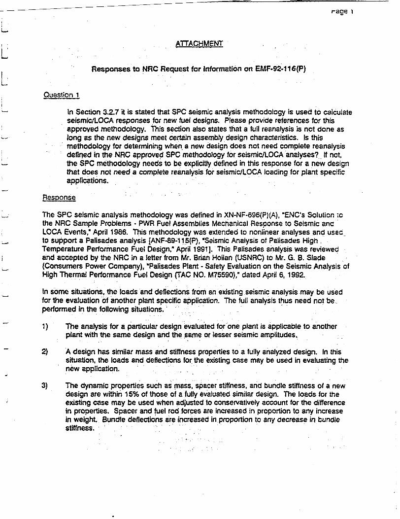
r-age I
ATTACHMENT
Responses to NRC Request for Information on EMF-92-116(P)
Question 1
In Section 3.2.7 it is stated that SPC seismic analysis methodology is used to calculate seismic/LOCA responses for new fuel designs. Please provide references for this approved methodology. This section also states that a full reanalysis is not done as long as the new designs meet certain assembly design characteristics. Is this methodology for determining when a new design does not need complete reanalysis defined in the NRC approved SPC methodology for seismic/LOCA analyses? If not, the SPC methodology needs to be explicitly defined in this response for a new design that does not need a complete reanalysis for seismiciLOCA loading for plant specific applications.
Response
The SPC seismic analysis methodology was defined in XN-NF-696(P)(A), "ENC's Solution ,o the NRC Sample Problems - PWR Fuel Assemblies Mechanical Response to Seismic anc LOCA Events," April 1986. This methodology was extended to nonlinear analyses and usec to support a Palisades analysis [ANF-89-1 15(P), "Seismic Analysis of Palisades High Temperature Performance Fuel Design," April 1991]. This Palisades analysis was reviewed and accepted by the NRC in a letter from Mr. Brian Holian (USNRC) to Mr. G. B. Slade (Consumers Power Company), *Palisades Plant - Safety Evaluation on the Seismic Analysis of High Thermal Performance Fuel Design (TAC NO. M75590)," dated April 6, 1992.
In some situations, the loads and deflections from an existing seismic analysis may be used for the evaluation of another plant specific application. The full analysis thus need not be performed in the following situations.
1) The analysis for a particular design evaluated for one plant is applicable to another plant with the same design and the same or lesser seismic amplitudes.
2) A design has similar mass and stiffness properties to a fully analyzed design. In this situation, the loads and deflections for the existing case may be used in evaluating the new application.
3) The dynamic properties such as mass, spacer stiffness, and bundle stiffness of a new design are within 15% of those of a fully evaluated similar design. The loads for the existing case may be used when adjusted to conservatively account for the difference in properties. Spacer and fuel rod forces are increased in proportion to any increase in weight. Bundle deflections are increased in proportion to any decrease in bundle stiffness.
Page 2
4) A design is substantially different from an analyzed design but analyses for other inputs have been performed which show that the use of loads from the existing plant specific analysis will be conservative. In this situation, other analyses or sensitivity studies have shown improved performance for the new design, indicating that it will provide equal or improved performance in the plant application under consideration.
Question 2
Please provide further information on what kind of fretting wear tests (Section 3.3.3) SPC performs for new spacer designs and intermediate flow spacers. 'Are flow tests performed and if so, what are the range of flow conditions considered and do these
envelope all flow conditions for SPC assemblies? What criteria are used to determine if a fretting wear test is needed for a given design change. Also, are there other design changes that could impact fretting wear such as flow characteristics due to inlet flow nozzle and bypass flow changes, etc? What post irradiation tests does SPC perform on the spacer springs to verify that they have adequate loads at high burnup levels to prevent fretting wear and are these tests performed on iead test assembiies with the new spacer designs?
Resoonse
SPC performs fretting wear tests on fuel assembly designs in its Portable Hydraulic Test Facility (PHTF). The PHTF has the capability to perform fretting wear tests on full size fuel assemblies with spacers, Intermediate Flow Mixers (IFMs), tie plates, and fuel rods configured to the requirements of the test.
Fretting wear test parameters include defining the test assembly configuration and test flow conditions. Generally the test flow conditions are conducted for fretting tests at the maximum dynamic flow conditions expected for the particular reactor type. The forces created by the flow are calculated by the Padoussis methodology to assure that the hydraulic forces seen in the test bound those expected from operating reactors. Other conditions considered include inlet nozzle and by-pass flow conditions. SPC spacers and IFMs are designed with a zero net flow directed away from the spring assembly. Therefore, by-pass flow is generally not accounted for in the test. Contact/interference forces are also parameters that are tested, and include tests with gaps to bound potential end-of-life conditions.
When SPC changes the fuel assembly hydraulic characteristics, e.g., with a new spacer or IFM, a fretting wear assessment is performed to determine if a fretting wear test is needed. This assessment is based on the expected impact of the change to a previously tested design. For example, a change to the strip thickness should probably not prompt a fretting wear test, but a change to the spring contact configuration' could.
To date, SPC has supplied fuel to approximately 30 PWR plants. This total includes introduction of HTP leads in 14xl 4, 16x1 6, and 18x1 8 plants and reloads in CE 1 5x1 5 as well as Westinghouse 15x1 5 and 17x1 7 plants. All of these cases required the new SPC. fuel to co-reside with fuel designed by other fuel vendors including Westinghouse, CE, KWU, and Framatome. This history of mixed cores includes the introduction of different fuel rod
Page 3
diameters, IFMs, and a large variety of spacer and lower tie plate designs. SPC has experienced no adverse spacer fretting wear resulting from the introduction of SPC fuel into a reactor core.
During 1993 poolside examinations were conducted at 8 PWRs and since 1979 a total of 119 poolside examinations have been conducted at PWRs. Examinations may be performed on reload fuel or lead assemblies. Most of these poolside inspections include examination and measurement activities such as visual, eddy current, and rod withdrawal force, which are capable of determining if fretting corrosion has occurred. Since 1970, 6 fuel rod failures have been attributed to spacer/fuel rod fretting out of a total of 1,867,644 PWR fuel rods under irradiation. The 6 failures were manufacturing related and did not result from design related operational problems. The fretting failure at Palisades is most likely attributable to core baffle interaction and has not been established as a spacer/fuel rod fretting problem.
Question 3
What is the cladding wall reduction value used for stress analyses and why shouldn this value also be used for other mechanical analyses such as for c!adding fatigue? Also, what is the equivalent oxide thickness based on the cladding wall reduction value?
Response
Steady-state stress analysis uses an end of life wall reduction of j Jdue to external corrosion of the cladding. The analysis conservatively assumes a uniform wall reduction around the cladding circumference. AC ] wall reduction of metal corresponds to [ E J of oxide.
Cladding fatigue resulting from cyclic mechanical strains during normal operation transients is determined by fatigue analysis techniques. The total fatigue represents a summation of fatigue damage from several types of transients. A transients contribution to total fatigue damage is calculated at the times during the operating history of the fuel where the transient is expected to occur. Conditions for the transient are calculated by RODEX2 and the transient ramp is performed by RAMPEX. Transients are applied at times representing hot and cold startups and mid-cycle power changes and therefore represent times where wall thinning is less that the end of life value.
Conservatism in the analysis precludes the need to continuously change code input for cladding dimensions in order to account for the wall thinning by corrosion during the fuel lifetime. Threshold benchmarking of RAMPEX includes the effects of wall thinning due to corrosion since the tests were conducted on a variety of commercial reactor irradiated fuel rods. SPC's criteria limit for cumulative fatigue damage is set at 67% of the design fatigue lifetime for Zircaloy cladding, and the fatigue cycles used for this determination conservatively bound potential rod power maneuvering.
Page 4
Question 4
Please demonstrate that the SPC corrosion model is applicable to high primary
coolant temperature plants up to rod average burnups of 62 GWd/MTM by
comparison to fuel rod corrosion data from these plants.
Resoonse
SPC does not at this time have the corrosion data needed to demonstrate the applicability of
the SPC corrosion model to 62 GWd/MTM for high temperature PWRs. Corrosion
measurement data from fuel in the Gosgen reactor is expected in June 1994. The data will
represent SPC cladding at exposures up to 60 GWd/MTM. At present we will continue to
take restrictions on the burnup of fuel in high temperature PWRs based on the available data.
We anticipate the new data will continue to be bounded by the current model.
The SPC corrosion correlation uses an enhancement factor based on experimental data. The
corrosion data from high temperature plants indicate that the standard Zircaloy-4 corrosicn
will be unacceptably high for the projected end-of-life exposures. Therefore, for the hign
temperature plants, SPC will use the optimized Zircaloy-4 or duplex cladding. Optimized
Zircaloy-4.fabricated with tighter tolerances on the constituent and the tin content biased to
the low range of the allowed content. Duplex cladding has a thin outer layer of a zirconium
alloy which is more resistant to waterside corrosion than Zircaloy-4.
SPC has several corrosion lead test programs in high temperature reactors. The lead
assemblies for the optimized'Zircaloy-4 with the highest exposures are at the Gosgen reactor.
which has a coolant exit temperature of 628°F. The examinations for fuel rods with up to
60 GWdi/MTU is scheduled for 1994. Previous examinations demonstrate the acceptable
corrosion behavior of the optimized Zircaloy-4 to peak rod exposures of about 55 GWd/MTU.
The lead programs for the duplex cladding have reached rod exposures of 55 GWd/MTU.
The inspections of this cladding indicate superior corrosion performance when_ compared with
the optimized Zircaloy-4 material. At the 55 GWd/MTU exposure, the corrosion rate of this
duplex cladding appears to be about half that of the optimized cladding.
SPC will continue with these programs to verify the adequacy of the SPC corrosion
correlation.
Question 5
Section 4.1.1 (Hydraulic Compatibility) (p.4-1) states that the hydraulic resistance of
the reload assemblies shall be "sufficiently Similar" to existing fuel to ensure that the
core performance will be "acceptable from a thermal margin performance viewpoint."
What criteria are used on total core, bypass, and assembly flow distributions to
judge whether the design has "sufficient similarity" to other designs in a core?
Page 5
What parameters are considered important in determining the hydraulic characteristics of a fuel bundle with respect to thermal margin performance? (If existing NRC approved methodology will be used to make these determinations, please reference them appropriately.)
Response
SPC has an NRC approved methodology for performing analyses of mixed core configurations. This methodology is described in XN-NF-82-21(P)(A), Revision 1, OApplication of Exxon Nuclear Company PWR Thermal Margin Methodology to Mixed Core Configuration," September 1983. The methodology describes how licensing analyses are performed in mixed cores for fuel designs with different rod designs and pressure drops at the spacer, upper tie plate and lower tie plate locations. The methodology explicitly calculates the axial and radial flow distributions in a mixed core and addresses the impact on DNBR and fuel centerline melt.
Any overall assembly pressure drop differences are also evaluated with respect to impac: cn total core and bypass flow. These flow impacts are also accounted for in the calculation of the DNBR and fuel centerline melt criteria.
Question 6
Section 4.1.2 (Thermal Margin Performance) (p.4-2) states that "For new fuel designs and changes in features, usage of the correlations is reviewed and justified."
What criteria, design variables and correlation variables will be used to justify whether or not a new fuel design falls within the data range of the variables of an existing ONB correlation?
If a new fuel design does not fit within the data range of an existing correlation,
will a new correlation be developed and submitted to NRC for review?
Response
SPC develops DNBR correlations to cover a range of coolant conditions and fuel design parameters. These parameter ranges are included in the ONBR correlation reports provided for NRC review and approval. The coolant conditions are pressure, local mass flux, inlet enthalpy and local quality and the fuel design parameters are fuel rod diameter, fuel rod pitch. axial spacer span, hydraulic diameter and heated length. A fuel design is evaluated relative to the fuel design parameters before each application of a DNBR correlation to insure that the fuel design is covered by the correlation. The coolant parameters are evaluated during the XCOBRA-IIIC DNBR calculation and a message printed in the code output if the coolant conditions are out of range.
Page 6
The SPC developed DNBR correlations are generally related to a specific SPC spacer design.
For example, XNB covers the SPC bi-metallic spacer design and the HTP correlation covers
the SPC HTP and HTP/IFM spacer designs. If SPC develops a new fuel/spacer design, SPC
would generally perform the required CHF testing to support a new spacer specific DNBR
correlation. This correlation would be documented and submitted to the NRC for review and
approval.
Should a parameter of an existing fuel design be somewhat outside an existing DNBR
correlation, one of three approaches is generally used. The first approach is to treat the
parameter in a conservative manner. For example, if the spacer span should be slightly
below the correlation range, then the minimum spacer span covered by the correlation could
be used. This would result in the calculation of a conservatively low DNBR value. The
second approach would be to run a CHF test to confirm that the DNBR correlation is
conservatively applicable to the expanded parameter range. If neither of these two
approaches is successful, the third approach is to modify the fuel design to bring it within the
DNBR correlation ranges or develop a new DNB correlation for NRC review.
SIEMENS
August 23,1994 RAC:94:118
Dr. S. L Wu Reactor Systems Branch Division of Engineering and System Technology Office of Nuclear Reactor Regulation U.S. Nuclear Regulatory Commission Washington, D.C. 20555
Dear Dr. Wu:
Criteria for PWR Rod and Assembly Growth Correlation
Reference: EMF-92-116(P), "Generic Mechanical Design Criteria for PWR Fuel Designs." Siemens Power Corporation, July 1992.
Attached is the criteria for establishing the PWR rod and assembly growth correlations, and a description of the methodology that uses these correlations. As we discussed, this information is being submitted as part of the NRC review of the referenced topical report.
Siemens Power Corporation considers the information contained in this attachment to be proprietary. The affidavit submitted with the original submittal of the topical report provides the support for withholding the information in this attachment from public disclosure, as required by 10 CFR 2.790(b).
If you have questions, or if I can be of further assistance, please call me at (509) 375-8290.
Very truly yours,
R. A. Copeland, Manager
Product Ucensing
/smg bc: A. Reparaz
Attachment J. R. Tandy File/LB
- cc: Mr. C. E. Beyer (PNL) Mr. L E. Phillips (USNRC)
Siemens Power Corporation
Nuclear Division - Engineering and Manufacturing Facility
2101 Horn Rapids Road, PO Box 130 Richltand, WA 99352-0130 Tel: (509) 375-8100 Fax: (509) 375.8402
ATTACHMENT
Rod and Assembly Growth Correlations and Criteria
Siemens Power Corporation's (SPC) fuel assembly and fuel rod growth correlations are established based on irradiation data. The correlations use irradiation data to determine nominal growth values, then include conservative upper and lower bounding growth curves. These bounding curves are then used in the fuel design calculation to establish the fuel assembly growth and differential fuel assembly to fuel rod growth.
SPC's generic PWR design criteria includes the methodology for determination of the upper and lower bounding growth limits for fuel assemblies and the upper bounding limit for fuel rods. Using this methodology, new growth information can be incorporated into the correlation without additional NRC review.
DesiQn Evaluations
Irradiation-induced growth of fuel assemblies and differential growth of fuel assembly and fuel rod are evaluated as part of each fuel design. Fuel assembly growth is a result of guide tube or guide bar growth and is influenced by the holddown forces exerted on the fuel assembly by the reactor upper core plate. Holddown forces restrict the free growth of the fuel assembly since the force places a compressive axial load on the guide tubes.
Guide tubes and guide bars are heat treated to fully anneal the zircaloy material. Annealed Zircaloy-4 exhibits lower growth rate at lower fast fluence followed by a transition to a higher growth rate. SPC's growth correlation transitions this growth rate at a fast fluence of 8x10²¹ n/cm2 . This transition represents a change from fully annealed Zircaloy-4 growth to a growth value representative of cold worked material.
Maximum fuel assembly growth is determined based on the upper bounding growth curve. Worst case tolerances of fuel assembly dimensions are used and the fuel assembly must remain within the working range of the holddown springs or within allowable growth space of the reactor core.
Differential fuel assembly to fuel rod growth is calculated based on minimum assembly growth and maximum fuel rod growth. Thus, the minimum gap between the fuel assembly cage and fuel rods is determined and can limit the lifetime of fuel. Since fuel rods are fabricated with cold worked stress relieved cladding and are not under compression, the irradiation-induced growth is more rapid than the fuel assembly. As a result, the gap tends to decrease with increasing fluence. Design criteria requires that the fuel rod shall not grow to contact both upper and lower tie plates. Calculations are performed using worst case tolerances.
Growth Correlation Criteria
Fuel assembly and fuel rod growth correlations presented in SPC mechanical design reports are based on irradiation data. Data obtained to date on guide tube and guide bar growth indicate that fully annealed Zircaloy-4 exhibits two distinct growth rates. Initially, annealed Zircaloy-4 growth is relatively low up to a fast fluence of 8x1 02' n/cm2 . Past this point, the growth rate of Zircaloy-4 changes to that of cold worked material. Consequently, growth
above 8x10²¹ n/cm2 is determined at the cold worked Zlrcaloy-4 growth rate. In the
previously approved designs, the upper and lower bounding curves enveloping this data were
conservatively drawn and used in the fuel design calculations. Because these curves were
approved by the NRC, additional data could not be included into the data base without
subsequent NRC review.
SPC oroposes to use the same linear form of the correlation with the slope transition at
8x10²¹ n/cm2 , and establish the upper and lower bounding curve estimate based on a 95/95
confidence level for the lower region of the curve.' Umits for the higher exposure region
(higher growth rate) of the curve will begin at the 95/95 values at the transition then proceed
parallel the nominal data. Using this method, a correlation will be established for each type of
PWR reactor with unique holddown characteristics. Figure 1 shows the correlation ana 95/95
estimates for PWRs utilizing 2-leaf holddown springs. Using this criteria for establishing the
correlation, the fuel assembly growth correlation can be updated as new data becomes
available and maintain the margin approved by the NRC without additional NRC review.
Similarly, fuel rod growth can be represented by a linear fit of irradiation data. There is no
change in slope at higher fast fluences because fuel rod cladding is cold worked and stress
relieved. Previously, the upper estimate of the fuel rod growth correlation was established by
drawing a bounding line. As with fuel assembly growth, SPC proposes to calculate the upper
limit line based on a 95/95 confidence limit prediction of the data. Figure 2 shows the
correlation and the 95/95 upper level for the current data base. The fuel rod data base can
then be updated to include additional data as it becomes available While maintaining the
margin approved by the NRC without additional review.
The methodology to use these correlations would be unchanged. The worst case
dimensions and a deterministic combination of 95/95 curves will be used to perform the
design evaluations.
LL
rn
CD
13
cn
igL ED
a)
LL
U. Prlim SIL 0,)L49311 P LQ.*IM SEIAAJaýxDU701aMU24La.AIIY. TDWF 90 &M
Figure 2 SPC PWR Assembly Growth (versus Fast Fluence)
I I E.. ~. Li L 4-. 'L~ iL.~. 9 *~. , L~ &J L & 7' i
I
November 16, 1994 RAC:94:172
Dr. S. L. Wu Reactor Systems Branch U. S. Nuclear Regulatory Commission Washington, D.C. 20555-0001
Dear Dr. Wu:
Responses to NRC Request for Information on EMF-92-116(P)
In a September 1994 telephone conversaticn with you ano the PNL reviewer, Carl Beyer, there were some additional requests for information concerning the PWR generic criteria topical report, EMF-92-1 16(P). Attached are the responses to these requests.
Please consider the information contained in these responses to be proprietary to Siemens Power Corporation. The affidavit provided with the original submittal of the topical report satisfies the requirements of 2.790(b) to support withholding of the attachment from public disclosure.
If you have any additional questions, or if I can be of further assistance, please call me at (509) 375-8290.
Very trulY yours, S"
R. A. Copeland, Manager Product Licensing
/smg
Attachment
cc: Mr. C. E. Beyer (PNL)
bcc: F. T. Adams D. E. Hershberger T. M. Howe A. Reparaz S. H. Shann J. R. Tandy L. E. Van Swam FileiLB
Siemens Power Corporation
-C.:. . -aA CS F:.-: ;EC-.c 2`-5-3 1 0luc:ear :M~
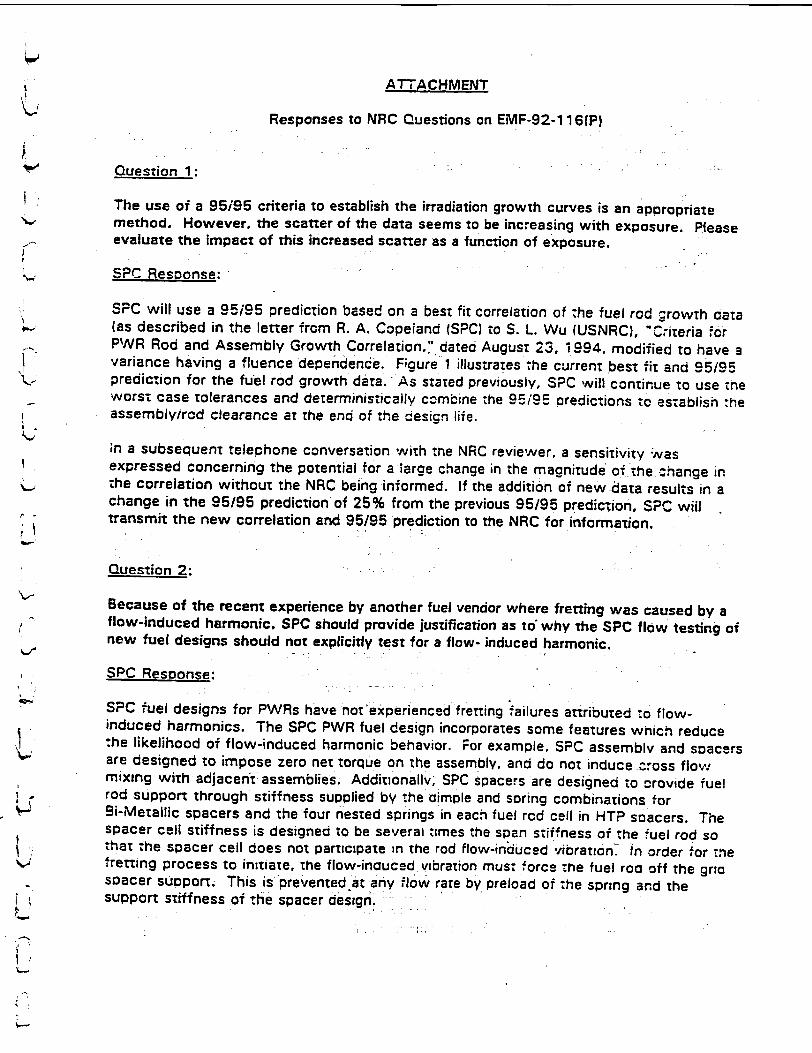
ATTACHMENT
Responses to NRC Questions on EMF-92-116(P)
Question 1:
The use of a 95/95 criteria to establish the irradiation growth curves is an aooropriate method. However, the scatter of the data seems to be increasing with exposure. Please evaluate the impact of this increased scatter as a function of exposure.
SPC Response:
SPC will use a 95i95 prediction based on a best fit correlation of -he fuel rod growTh data (as described in the letter from R. A. Copeland (SPC) to S. L. Wu (USNRC), "Coiteria #or PWR Rod and Assembly Growth Correlation." dated August 23, 1994, modified to have a variance having a fluence dependence. Figure 1 illustrates the current best fit and .95i95 prediction for the fuel rod growth data. As stated previously, SPC will continue to use tne worst case tolerances and deterministically cOmbine the 9i/95 predictions to establish :he assembly/rod clearance at the end of the cesign life.
;n a subsequent telephone conversation with the NRC reviewer, a sensitivity Was expressed concerning the potential for a large change in the magnitude of the .change in the correlation without the NRC being informed. If the addition of new-data results in a change in the 95/95 prediction of 25% from the previous 95/95 prediction, SPC will transmit the new correlation and 95/95 prediction to the NRC for information.
Question 2:
Because of the recent experience by another fuel vendor where fretting was caused by a flow-induced harmonic. SPC should provide justification as to' why the SPC flow testing of new fuel designs should not explicitly test for a flow- induced harmonic.
SPC Resoonse:
SPC fuel designs for PWRs have not experienced fretting failures attributed to flowinduced harmonics. The SPC PWR fuel design incorporates some features which reduce the likelihood of flow-induced harmonic behavior. For example, SPC assembly and spacers are designed to impose zero net torque on the assembly, and do not induce Cross flow mixing with adjacent assemblies. AdditionalWl, SPC spacers are designed to -rovide fuel rod support through stiffness supplied by the aimple and soring combinations for Si-Metallic spacers and the four nested springs in each fuel rod cell in HTP soacers. The spacer cell stiffness is designed to be several times the span stiffness of the fuel rod so that the spacer cell does not participate =n the rod flow-induced vibratin. In order nor .e Iretting process to initiate, the flow-inouced vibration must, force the fuel rod off the gra soacer suoport. This is prevented at any flow rate by preload of the spring and the support stiffness of the spacer design.'
01
Question 3:
Cross-flow is a significant design concern because of fretting. The NRC is aware that SPC addresses the cross-flow when evaluating a new design and would like for SPC to formally document that this assessment is performed.
SPC Resoonse:
Although there is no defined accectance criteria for cross-flow, SPC uses :.-e flow zest data on the SPC design and the co-resident fuel to examine -he potential tcr rcass-flcw and fretting resulting from this cross-flow, particularly at the lower zle olate.
Question 4:
In the letter referenced in Response 1, SPC commented that additional corrosion data was to be obtained in the summer of 1994. If this data is available, the reviewer would like to have it submitted.
SPC Resoonse:
Figure 2 shows the data obtained this June from tne G-sgen PWR. a high :erncerature German reactor. The open circles are the recent data, and the ciosed circles are the previous data. The open circles are the production optimized Zircaloy-4 cladding used. As this data demonstrates, the corrosion performance of the optimized Zircaloy continues to be acceptable. Therefore, SPC concludes that, with the restriction that SPC use the optimized Zircaloy for the high temperature plants. the corrosion performance of the fuel will be acceptable to the currently approved exposure limits.
Question 5:
The description of when SPC develops a new DNB correlation discusses when the correlation input for a design is beyond the data base as a potential cause for creating a new correlation. The reviewer would like more information concerning when design changes, e.g., spacer changes, can precipitate a new correlation.
SPC Resoonse:
The brief history below illustrates several situations which have led to the develoament of a new DNB correlation. A more direct discussion of design changes as they affect DNB correlation applicability and development foilows the historical discussion.
Past SPC DNB Correlation Efforts:
In its over 25 years of nuclear fuel supply. SPC has develooed three DNB correlations for use in U.S. licensing. The XNB correlation was develooed to accurately describe the DNB performance of the then-standard SPC bi-metallic spacer design. The ANFP correlation was developed to describe the DNB performance of SPC's present standard HTP and
HTP!IFM spacer designs for Westinghouse reactors of 12 foot heated length. The HTP correlation is an extension of the ANFP correlation vaiid for various heated iengths and HTP and HTP!IFM fuels for reactors of other manufacture.
SPC originally used the W-3 correlation fcr its bi-metailic spacer cesigns. The -.I-3 correlation was quite conservative in its predictions or -he bi-metailic soacer. The XNB correlation was develooed to provide more accurate.xredictions of the bi-metailic spacer performance, permitting greater flexibility in core design. The need for octimizec predictions of a particular fuel design's DNB performance may !ead to the -Jeveiooment of a new DNB correlation.
The HTP spacer represents a new concept in spacer design incorporating advances in mechanical and thermal-hydrauiic performance. Improved DNB performance is ootained by inducing a swirling component to flow downstream of the soacer, a mechanism fundamentally different from the simple deflection of flow caused by the mixing vanes of the bi-metailic spacer. To afford accurate prediction of the improvedperformance of the HTP spacer design, the ANFP DNB correlation was developed. Thus, a fundamental change in spacer design may'impel the development of a new DNB correlation.
The ANFP correlation also describes the DNB performance improvement resulting from intermediate flow mixers (IFMs), which are non-structural grids piaced between structurai spacers to improve flow mixing. A new DNB correlation may follow on the introduction of a new assembly component which affects DNB performance.
SPC supplies HTP and HTP/IFM fuel for PWRs of Combustion Engineering, Westinghouse, Siemens, and other NSSS vendors. A large amount of DNB data may be necessary to support licensing of the many fuel arrays represented in this diverse scope of suOply, requiring a significant amount of time to obtain (5 years for the HTP designs, for examole). Like ANFP, a correlation may be developed on an initial subset of this large data base to meet licensing schedule pressures. The HTP correlation was developed on the entire HTP and HTP'IFM data base .o provide a
single predictive tool for the reactor types for which HTP fuel designs may be soid.
Handling Component Design Modifications:
Fuel rod internal design or tie plate design do not significantly affect DNB performance. Change of these components of the fuel design will typically not require the development of a new DNB correlation.
Modifications to an existing spacer design are carefully evaluated for impact on DNB performance. Such modifications include changes in spacer strip thickness, a shift from ring-type spacer capture aevices to direct spacer-to-guide tube welding, changed spacer soring design, altered mixing vane or flow nozzle configuration, or changed siceplate aesign. When sound engineering judgement deems it appropriate, additional DNB testing is performed to ascertain the effect of sucn design modifications. Changes in fuet rod pitcn. outside diameter, or active length are treated similarly if outside the range of apokicability of the existing correlation.
,I esZ results nc::3-te :n'at the design cnange causes no significant per-ur-aticr. of. ONE zerrzcrmance. ;-;aa~ns notr necessarv. Most spacer de-sign m-ocifications nave lailer,
Ths Lec~c-%. -- es zn canages /;ieicing major CJNB cerformianc aeeisnv *esu.1Zr, 3 e-~orriaton r-:-. esicn criange yielcing 3 S;gnific~nrt 'ýNE zerfcrmance :efic:TL N!:i
isuailv -. t --e rc:-::c-s=tea 'n tne final issernoiv ies~gn. -L~T rncorcoraTec :%oil -Jemanc 3 -nCciTfiC3-9on ef x s-t:ng *DNS corregaticn.
Question 6:
In a subsequent :ete-r~cne conversation with the NRC reviewer, he requested a descriolion of the approacin used :-v SPC to define a fuel surveillance program.
SPC Pescornse:
NewN SPC fue.l 3es gns nicorporate proven design features :n comoination wvith new aesic~n 7eatures :o r-.=rc-.e a -ei oerformance cnaracteristics. SPC 'ntrocuces new fuei desicrs -nrougn '-eac u.e- AsSaeroiv programs -Nhic.;- .nc:uae survetilance cf zhe ;n-r-eac::-r :er~crrm-ance _-T :-P- :es~gn features.
71ne par-iculars :- aaa Fuei Assembly surveillance progra m- eoeno . :n ::,e scec_;fics zJ, .:anewv ue,:a-! zestures and are dieveicpea on a case snecffic basis fn ::cccerat-cr
Nvttr. me -jtili-,/i :r -..cse reactor the Lead '--el Assemblies are irraciatea.
SPC can oerfcrrn :er~aiied visual inscec-tion of fuel assembijes and make Pcoolsce measurements --; :ne -tesign parameters as needed to support :he sco pe deveiopea 'or -zhe oarticuier leac. ass-err~iy program. Examples of the types Of measurements :hat can be-erf'orrred irnc~uce:
-cc :A:arr-eter profilometrv * x::e -:-:ckness * cc ernc-r
fss-:cn: =as release Pe,.et ::iumn location
* ax:a=i -.cw.er profile * ~azzir~c :jefec-.s * c!--:o-rza spacing * assmc~vlength.
j

S.PrIbe i. 13-07M A*X U VJ01 4BAr1 tI17* i3Mft438U.ADTttj0.? to 10 4a
Figure I SPC Assembly Averaged PWR Rod Growth (vs Fast Fluience)I
2 Cladding ColititJoll
I L-ý-4 tL ý IL ý il -,%" I -
January 31, 1995 RAC:95:019
Dr. S. L. Wu Reactor Systems Branch Division of Engineering and System Technology Office of Nuclear Reactor Regulation U.S. Nuclear Regulatory Commission Washington, D.C. 20555
-Cear Dr. Wu:
- Response to Additional NRC Question on EMF-92-116(P)
In our telephone conversation with you arc Mr. Beyer of PNL. :nere wevsre :wo =ddi;tcn-i •'-' ciarifications needed to suppcr, the review o- 2MF-92-1 I (PI, :he generic PW'R desicn cr-re:-a
topical report. Attached are the responses to these two requests. P!ease consider the ' information contained in these responses to be proprietary to Siemens Power Corporation. The
affidavit supplied with the original submittal satisfies the requirements of 10 CFR 2.790(b) to - allow withholding from public disclosure.
If you have any additional questions, or if I can be of further assistance, please call me at (509) 375-8290.
. Very truly yours,
R. A. Copeland, Manager Product Licensing
stag
L_ Artacnment
c•: Mr. C. Beyer !PNL.c :c:" . . A. M.
,R. C. D. E.
;M.
J. W. F-ieiLB
Adams Brown Gottula Hersnberger Howe Hulsman
Siemens Power Corporation
-lcta .3.. u- .�a. �
.1� -
Attachment
Response to Additional NRC Question on EMF-92-116(P)
•uestion:
In -he reference, :he resoonse to Question 5 states: "if test resuits indicate "ha: -me :es cn change -causes no significant perturbation of DNB performance. re-correlation is -7:c necessary. What criterion is used :o judge whether the test results represent a s.gnificant :er.urcaz~cn?
Response:
!n SPC's experience. at !east two siruations have arisen whic.: :nvoivec :ne aco;.:',C,sightlv cifferent :r:ter:a:
"= zesicr zaram eter ".r.ic.n ;s nc "ecreserrec :r :7e Z-X.S:.N:.r-_. e.C:., Assume :na. zhe sz-acer .s Bi!-erec :!. scme -;-!Ecre.•.-.. X ar IN..::e. :NE :ees rnav ze oer,:crm. e: ;s;nc a test zundle dcer:-cai in res:e::s :z-- : -:c -sz.
n ver:rn: . V'.:c havinc .- n.e ' soc .r. . ' , sut :4 . -"- ".-_- air zo rtct :iffer tv an amcunrt ;reater :nan :n-e :.raole-.c-zunc~ e reoeatccmj;.. -:v.O... ";r ,:ne DNB test fac:jit*/, .nen :ne design change would ze udced tc ,nave nac. no ;JcrIcart effect on ONE performance.
2) A design parameter on which the correlation depends is extended beyond zhe correlation limits. As an example, assume an increase in the fuel assembly spacer pitch from 20" (within present correlation limits) to 50" (outside of present correlation limits). A DNB cest may be performed using a test bundle having the extended pitch. The result is exoectea :o be influenced significantly by the extended soacer pitch. The DNB correlation -s aoplicaole without change if t predicts mhe .est oata on a 95:95 basis witnin the existing correlation safety limit, or if adaition of tne test oata :o thne ccrreiaton data base ,ielas a 95i95 safety limit equal to or less t'han Zhe existing safety limit.
if a different situation were -o arise, SPC would devise a criterion basea on a simijar 3cc•icotion of stancarcd engineering crincioies.
;2ues,;c r:
SPC snhcuc exoiain INnV -e fretting faiiure at Palisaces :s .nc 3 .:lo;, nCLC•.C ':ra.:o :ncern such as seen cr Vantace e.PC snou:caiso .cescr:,e -e :esign. -c:'r.- : - mace -orec!uce :.u: -r. -cz rre.ces of "re "retinc =rcorem :.-.at :ý= rrec :!t .i.rsacz.s.
Resconse:
SPC has continued its investigation of the P3lisades 1-024 fuel assembly failure. The investigation has included a review of the reactor noise analysis. The frequencies apparent in the power spectral density evaluation of :he ex-core detectors 0o not show a resonance at the
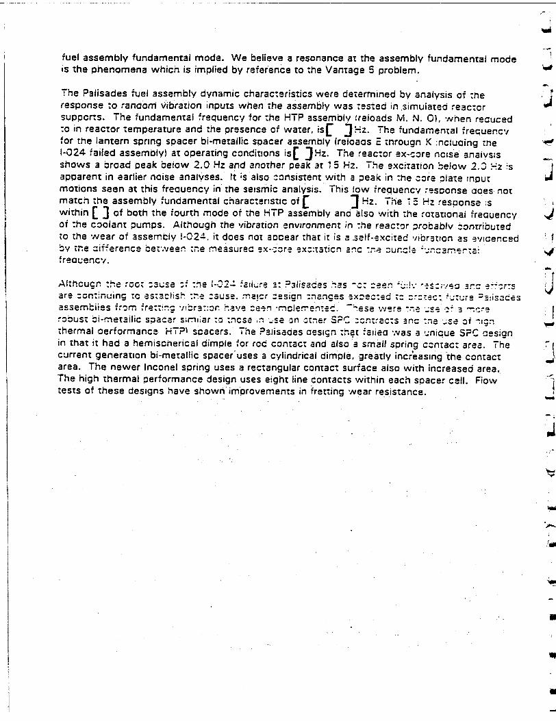
fuel assembly fundamental mode. We believe a resonance at the assembly fundamental mode is the phenomena which is implied by reference to the Vantage 5 problem.
The Palisades fuel assembly dynamic characteristics were determined by analysis of :he response to random Vibration inputs when the assembly was tested in .simuiated reactor suppcrts. The fundamental frequency for -he HTP assembly freloads M. N. 0), wnen recuced :o in reactor temperature and the presence of water, is• I3Hz. The fundamental frecuenc,/ for the lantern spring spacer bi-metallic spacer assembly freioacs E througn K :nciuaing the 1-024 failed assembly) at operating conditions isA 3Hz. The reactor ex-core ncise anaivszs shows a broad peak below 2.0 Hz and another peak at 1 5 Hz. The excitation below 2.3 .'-H.z .s apparent in earlier noise analyses. It is also consistent with - peak in :he core plate input motions seen at this frecuency in the seismic analysis. This low frequency resconse aces not match the assembly fundamental characteristic of £ 3Hz. The 5Hz response -s within E J of both the fourth mode of the HTP assembly and also with the rotational freauency of :he coolant pumps. Although the vibration environment in :he reactor probably :ontributed to the wear of assemiyv !-024, it does not aocear that it is a self -excited vibration as evicenced by te cifference between the measurec ex-:;re -3x::taticn anc :-e. our, cle ;-:'cam=rna: freouencv.
Althcucn -he roct :suse ;, :ne •-024 aliure 3: R31lSadeS ýs z._. -c: :-B . So --e --e"n.--S are zommuing to as;as'ljs :-e cause. maicr :esign :nrianges -xcecte :ed z- tr: .-" . -- es assemb.iies from frettz.. *ibra-:or h.ae cc cn .mlernen.ec. Z.ese ,r. t.e _se- robust bi-metailic spacer s zriar to .rcse , se - n -.:zer $PO :cntracls Bno -. e -Se oi .Ign thermal oerformance HTPI scacers. The Pajisades desicn t-hat fafiea was a -nicue SPC cesign in that it had a hemiscnerical dimple for rod contact and also a small spring contacz are-a. The current generation bi-metallic spacer'uses a cylindrical dimple, greatly incr'easing the contact area. The newer Inconel spring uses a rectangular contact surface also with increased area. The high thermal performance design uses eight line contacts within each spacer cell. Fiow tests of these designs have shown improvements in fretting wear resistance.
IN
SIEMENS
October 12, 1 995 RAC:95: !36
Dr. S. L. Wu Reactor Systems Branch Division of Engineering and System Technology Office of Nuclear Reactor Reguiation U.S. Nuclear Regulatory Commission Washington. D.C. 20555
D e r ..O . '.I:
Documentation of NRC Review Requirement
,R.eference.: Letter, R. A. C-ceiand iSPC, .c S. L. 'US"..USNPC, "Resccrses -:NPC ecuest .or Infcrm-trcn on EMF--2-1 16. . C.. : 7N. >cvernoer 1.9. 1. c".
As you recuested 7n -ur --eteonone conversaticn on Octcber 92. .Sieme.s Power Corporation agrees with your reauirement to submit to the NRC for review any future reve:son :.o the growth model presented in the reference letter in excess of one standard deviation from this model.
If you have questions, or if I can be of additional assistance, please call me at (509) 375-8290.
Very truly yours,
R. A. Co ager
Product Licensing
sM a
cc: Mr. C. E. Beere PNLU
bcc: C. H.
A. R. M.
A. Brown D. Curet Reoara, S. Reynolds H. Smith
Siemens Power Corporation
Iuclear Oivision S'".fneerg S ,'Aanuac:ur-mPg
2101 Horn Raoes Road '0. Box 130 =icnaanO. 'IA .=93Z-0120
"el: 1509) 373.8100 :ix: '509) 375-8402
SIEMENS
June 30, 1997 HOC:97:068
Document Control Desk ATTN: Chief, Planning, Program and Management Support Branch U.S. Nuclear Regulatory Commission Washington, D.C. 20555
Response to Question on EMF-92-116(P)
Ref.: 1. EMF-92-116(P), "Generic Mechanical Design Criteria for PWR Fuel Designs," Siemens Power Corporation, July 1992.
Attached is an additional response to an NRC question on the referenced topical report. The "additional information was requested by the NRC reviewer, Dr. S. L. Wu, in recent discussions with me.
.V Siemens Power Corporation considers some of the information contained in the attached response to be proprietary to Siemens Power Corporation. This proprietary information is indicated by brackets, '[ 1". The affidavit provided with the original submittal of this report provides the necessary information required by 10 CFR 2.790(b) to support the withholding of
-• this proprietary information from public disclosure.
Yr If you have any questions, or if additional information is needed, please call me at (509) 375-8563.
t" Very truly yours,
H. Donald Curet, Manager Product Licensing
/smg
Attachment
cc: C. E. Beyer (PNNL) E. Y. Wang (USNRC) S. L. Wu (USNRC) Project No. 702
bc: C. A. Brown R. A. Copeland V. N. Gallacher A. Reparaz R. S. Reynolds M. H. Smith L. F. van Swam File/LB
Siemens Power Corporation
Nuclear Division Engineering & Manufacturing
2101 Horn Rapids Road P.O. Box 130 Richland. WA 99352-0130
Tel: Fax:
(509) 375-8100 (5091 375-8402
Page 1
Attachment - Response to Question on EMF-92-116(P)
A previous question from the NRC on the topical report EMF-92- 1 6, (Ref. 2), requested fuel rod corrosion data. In the time since the response was provided (Reference 1, Question 4), additional fuel rod corrosion data has become available. Also, in recent discussions with the NRC reviewer and the technical reviewer of the topical report, a comparison was requested as to how the SPC design limit compares with a 100 micron best estimate, peak local corrosion limit.
This response contains a review of the generic criteria for fuel rod oxidation provided in Section 3.3.4 of Reference 2. It describes in greater detail the oxidation criterion, summarizes how the criterion was developed, and demonstrates how SPC's chemistry and process optimized z'ircaloy-4 is performing compared to the approved prediction methodology and the oxidation design !imit. The optimized zircaloy-4 performance is shown in graphs comparing the SPC design corrosion correlation for different fuel designs with fuel rod corrosion measurements for thcse designs.
The design criterion for corrosion requires that the upper bou'nd oxidation calculated -,cr the peak axial location of the fuel rcd for the most limiting fuel rod design history shall be ,ess than [ 1. The design basis for SPC's corrosion methodology and criteria has been provided in reference 3. In that reference two main points are presented.
1) An oxidation prediction methodology was developed for design calculations whereby the design correlation bounds 95% of the peak measured data with 95% confidence.
2) A maximum design limit of[ .I was established for the highest oxidation axial location ýon the most limiting fuel rod in the core. This limit is conservatively established from data on fuel rods that have operated without failure to o ] Oxidation.
When the design prediction reaches the I criterion limit, the corresponding best estimate maximum for a fuel rod is I I microns. Therefore SPC's methodology with the I I bounding design criterion conservatively protects "00 microns best estimate peak local oxidation.
A large experience base has confirmed that the f I design limit for the maximum projected rod history is conservative for protecting fuel rod integrity. In the mid 1 9-0"s Siemens operated European reloads of a corrosion susceptible cladding to oxide thicknesses greater than [ I. A total of approximately 180,000 rods with susceptible cladding were irradiated From statistical considerations it is estimated that I I reached oxide thickness leveis in excess of f 1. This was estimated from the proportion of I I with oxide thickness in this range to a total of
Page 2
[. None of the rods with corrosion in the [ 1 range failed.
Approximately I ] that were irradiated for four cycles attained an oxide thickness of I ] or greater. Five rods out of the population of rods with corrosion in excess of [ ] failed near the end of their fourth cycle in the core. SPC thus considers that [ oxide thickness is the lower limit for corrosion induced failures of zircaloy cladding and conservatively takes [
.1 as the design criterion.
Since the approval of the corrosion methodology (Ref. 3) additional measured oxide data has been obtained. Experience at high burnup has shown that the design projections ;cr standard (tin near the mid-range of the ASTM specification) zircaloy-4 clad do not always conservatively bound the data. The experience with this non-optimized chemistry and processing zircaloy-4 cladding is illustrated in Figure 1. The figure shows the peak oxide measurement results for SPC's 15xl 5 high burnup lead assemblies, irradiated to a maximum rod burnup of I
Zircaloy-4 with optimized chemistry (tin content near the low enc of the ASTM specification) and optimized processing for improved corrosion cerformance has been used in SPC's full production since about 1990. Data has been cotained cn this clad type to burnups of I ,
I. Data obtained from measurements in high temperature piaPrts is included in the database. The measured data versus a typical design calculation for each PWR fuel type supplied by SPC in the U.S. is shown in Figures 2 through 5. The measured results are conservatively bounded by the reference design calculations. The optimized zircaloy-4 data is more tightly grouped than the previous data for standard zircaloy-4, and falls typically at or below the previous best estimate correlation.
-.
SPC previously provided oxide measurement data(l) on low tin zircaloy clad fuel rods in a hot KWU plant. These measurements included data on cladding with fully optimized chemistry and processing, and also low tin zircaloy precursor material that was not fully optimized with regard to processing. The plot of the measurement data, Figure 6, has been updated to include all measurements taken up to [ I rod burnup. The design calculation for a high burnup power history in this hot plant is also shown. The calculation projects a bounding oxide thickness of about [
1. The data indicates that the precursor material had a slightly higher corrosion rate than the full,, optimized low tin zircaloy-4 cladding. When compared with the design bound calcuiation this precursor and optimized cladding data demonstrate that SPC's methodology will be conservative for optimized clad over the approved burnup range.
Mild

Page 3
References:
1.. Letter, R. A. Copeland (SPC) to S. L. Wu (USNRC), "Responses to NRC Request for Information on EMF-92-1 16," RAC:94:172. November 6, 1994.
2. EMF-92-116(P), "Generic Mechanical Design Criteria for PWR Fuel Designs," Siemens Power Corporation, July 19942. 3. EMF-88-133(P)(A) and Supplement 1, "Qualification of Advanced Nuclear Fuels PWR Design Methodology for Rod Burnups of 62 GWd/MTU," Siemens Power Corporation, December 1991.
ain6ij
Figure 2.
Figure 3.
' V ai~jf6 rj-
- -I~ ) ~ --) --
--A
I
Fýgure 5.
A il-
r-- Fine) Ir : ( -
9
N(" 7ý (C r*-
iC-- r
Figure 6.
( - 'r --
SIEMENS
January 14, 1998 NRC:98:003
Document Control Desk ATTN: Chief, Planning, Program and Management Support Branch U.S. Nuclear Regulatory Commission Washington, D.C. 20555-0001
Response to Question on EMF-92-116(P)
bc: (w/attachment) C. A. Brown R. L. Feuerbacher V. N. Gallacher L. E. Hansen
J. S. Hcdm l T1. M. Howe
R. E. Narum C. M. Powers R. S. Reynolds M. H. Smith C" . L. F. van Swarded' FileiL-B
Ref.: 1. Letter, H. D. Curet (SPC) to NRC Document Control Desk, "Response to Question on EMF-92-116(P)," HDC:97:068, June 30, 1997. As suggested by Dr. S. L. Wu, Mr. Carl Beyer of PNNL was contacted regarding the concerns he mentioned to Dr. Wu related to Siemens' prediction of PWR corrosion data presented in the reference.
Mr. Beyer was called on August 27, 1997 and he expressed his concerns to Dr. Leo van Swam and Messrs. Charlie Brown and Don Curet. Siemens' response to Mr. Beyer's concerns are addressed in the attachment to this letter. The penultimate paragraph on page 2 of the attachment describes the implemented changes intended to eliminate Mr. Beyer's concerns. The transmittal of the attached response to the NRC was deliberately delayed in order to avoid a conflict with an ongoing review of Siemens Power Corporation's (SPC) topical reports regarding BWR burnup limits.
SPC considers some of the information contained in the attached response to be proprietary. This proprietary information is indicated by brackets, "[ ." The affidavit provided with the original submittal of this report provides the necessary information required by 10 CFR 2.790(b) to support the withholding of this proprietary information from public disclosure. If you have any questions or if additional information is needed, please call me at (509) 375-8563.
Very truly yours,
H. Donald Curet, Manager
Product Licensing
larn
Attachment
cc: C. E. Beyer (PNNL) S. L. Wu, (USNRC) E. Y. Wang, (USNRC) Project No. 702
Siemens Power Corporation
Nuc!ear Division Engineering I, Manutac:Lurang
^*01 Horn Ra•ams Roaw PO. Box :3c Ricnlanc. WA ?935:-0130
.• 09g 375-a1100 :5091 375-8402
;e:JX

NRC:98:003
Attachment Page 1
Response to Question on EMF-92-116(P) A previous question from the NRC on the topical report EMF-92-116(P}, iReference .), requested fuel rod corrosion data. In the time since the response was provided (Reference 2, Question 4), additional fuel rod corrosion data has become available. Also, in recent discussions with the NRC reviewer and the technical reviewer of the topical reoort. a comparison was requested as to how the SPC design limit compares with a 100 micron best estimate, peak local corrosion limit.
This response contains a review of the generic criteria for fuel rod oxidation provided in Section 3.3.4 of Reference 1. It describes in greater detail the oxidation criterion, summarizes how the criterion was developed, and demonstrates how SPC's chemistry and process optimized Zircaloy-4 is performing compared to the approved prediction methodology and the oxidation design limit. The optimized Zircaloy-4 performance is shown in graphs comparing the SPC design corrosion correlation for different fuel desicns with fuel rod corrosion measurements for those designs. SThe design criterion for corrosion requires that the upper bound oxidation calculated fcr the peak axial location of the fuel rod for the most limiting fuel rod design history shall be less than I 1. The design basis for SPC's corrosion methodology ana criteria has
been provided in Reference 3. In that reference two main points are presented. 1. An oxidation prediction methodology was developed for design calculations whereby the design correlation bounds 95% of the peak measured data with 95% confidence.
.1 2. A maximum design limit of f J was established for the highest oxidation axial location on the most limiting fuel rod in the core. This limit is conservativeiy established from data on fuel rods that have operated without failure to [ oxidation. When the design prediction reaches the [ I criterion limit, the corresponding best estimate maximum for a fuel rod is [ J microns. Therefore, SPC's methodology with the [ .1 bounding design criterion conservatively protects 100 microns best estimate peak local oxidation. A large excerience bas'e has confirmed that the [ d aesign Jimit for the maximum projected rod history is conservative for protecting fuel roa integrity. In :he mic I 9 80's Siemens operatec Eurcean reloads of a corrosion susceptibie cladaing to oxbde thic•Knesses greater than [. A toral of approximately .62,00C roas With susceotibie cladding were irradiated. From statistical consioerations it .s eszimatec :nat reacned oxide thickness ieveis in excess of I .i. This was est:mated from the propor-:on of f I rod measurements of oxide thickness in this range zo a totai of I. None of the rods with corrosion in ;he range failed.
NRC:98:003 Attachment
Page 2
Approximately [. ] that were irradiated for four
cycles attained an oxide thickness of [ ] or greater based on the proportion of
measurements above this level. Five rods out of the population of rods with corrosion in
excess of [ I failed near the end of their fourth cycle in the core. SPC thus
considers that I ] oxide thickness is the lower limit for corrosion induced
failures of Zircaloy cladding .and conservatively takes [ las
the design criterion.
Since the approval of the corrosion methodology (Reference 3), additional measured oxide
data has-been obtained. Experience at high burnup has shown that the design projections
for standard (tin near the mid-range of the ASTM specification) Zircaloy-4 clad do not
always conservatively bound the data. The experience with this non-optimized chemistry
and processing Zircaly-4 cladding is illustrated in Figure 1. The figure shows the peak
oxide measurement results for SPC's 15xl 5 high bumup lead assemblies, irradiated to a
maximum rod burnup of [
Zircaloy-4 with optimized chemistry (tin content near the low end of the ASTM
specification) and optimized processing for improved corrosion performance has been used
in SPC's full production since about 1990. Data has been obtained on this cladding type to
burnups of I Data obtained from measurements in high temperature plants is
included in the database.
The measured data are compared to a typical design calculation for each PWR fuel type
supplied by SPC in Figures 2 through 5. The optimized Zircaloy-4 data is more tightly
grouped than the previous data for standard Zircaloy-4. The measured results are
conservatively bounded by the design calculations.
SPC previously provided oxide measurement data (Reference 1) on low-tin Zircaloy clad
fuel rods in a high temperature KWU plant. The fuel cladding in this plant operated at high
inlet temperature and an aggressive power history that results in a high projected bounding
corrosion, and also in relatively high measured corrosion. The measurements included data
on cladding with fully optimized chemistry and processing, and also low-tin Zircaioy
precursor material that was not fully optimized with regard to processing. The plot of the
measured data, Figure 6, has been updated to include all measurements taken
,1. The data indicates that the orecursor material had a slightly higher
corrosion rate than the fully optimized low-tin Zircaloy-- cladding.
The averaoe oxide thickness and, standard deviation of " I at the
KWU plant at the higher burnuos were determined. The average oxide .hickness [
I for th I.e orecursor material is [ I at a burnup of
[. For -he octimized c!adding at a burnup of
the corresponding oxide thickness [h
138 microns]. These values are indicated in Figure 6. In order to conservatively bound the
above indicated 1 I values, about an [ 1 needs to
be added at the i I level to the upper bound corrosion projections.
Attachment Page 3
To achieve this increase the addition is applied as f.
] The moditied upper bound cesign calculation for the KWU plant, also shown in Figure 6, thus bounds the statistical limits on the data sets.
Current SPC calculations for U.S. plants are [.
] The adjusted calculations as compared to the data for typical U.S. plants are shown in Figures 7 through 10. Design calculations that do not reach f I are unchanged by the additionai uncertainty. These calculations are conservative with respect to the data and the [
I design limit. The addition to the upper bound will be applied to future corrosion projections. The modified correlation takes into account the observed accelerated oxide thickness accumulation above approximately [ J.
References:
1. EMF-92-116(P), "Generic Mechanical Design Criteria for PWR Fuel Designs," Siemer.s Power Corporation, July 1992.
2. Letter, R. A. Copeland (SPC) to S. L. Wu (NRC1, 'Responses to NRC Recues: fcr
Information on EMF-92-116(P)," RAC:94:172, November 6, 1994.
3. EMF-88-133(P)(A) and Supplement 1, "Qualification of Advanced Nuclear Fuels PWR Design Methodology for Rod Burnups of 62 GWd/MTU," Siemens Power Corporation, December 1991.
"711
0) c
E -
.1 1
NRC:98:003 Attachment
Page 5
NRC:98:003 Attachment
Page 6
I.
4I I
NRC:G-8:003 Attachment
Page 7
!C,
I I
NRC:98:003 Attachment
Page 8
I
_7
NRC:98:003
Attachment
Page 9
1i
U
A
U _ ___ __
NRC:98:003 Attachment
Page 10
1J
I I
N R C:98:003 Attachment Page 11
• II !
NRC:98:003 Attachment
Page 12
I'
FitItire lo.
EMF-92-116
Generic Mechanical Design Criteria for PWR Fuel Designs
July 1992
EMF-92-116 Page i
Table of Contents
Section Paaigce
1.0 INTRODUCTION ............................................. 1-1
2.0 SUMMARY AND CONCLUSIONS .................................. 2-1
3.0 GENERIC FUEL SYSTEM DESIGN CRITERIA .......................... 3-1
3.1 Objectives ..... . . ................ ... 3-1 32 Fuel Rod Coritera ..................... ............ 3-2 3.2.1 Internal Hydriding .................. 3-2 3.2.2 Cladding Collapse ....................................... 3-2 3.2.3 Overheating of Cladding ............................ ......... 3-3 3.2.4 Overheating of Fuel Pellets ............................... ....... 3-3 3.25 Stress and Strain Umlts................................... 3-4 3.2.6 Cladding Rupture ..................... 3-4 3.2.7 Fuel Rod Mechanical Fracturing .............................. 3-5 3.2.8 Fuel Densification and Swelling ............................... 3-5 3o3 Fuel System Criteria ..... .. .. 3-5 3.3.1 Stress, Strain, or Loading Umits on Assembly Components............ 3-6 3.3.2 Fatigue .............................. .................... 3-7 3.3.3 Fretting Wear .......................................... 3-7 3.3.4 Oxidation, Hydriding, and Crud Buildup ........................... 3-8 3.3.5 Rod Bow ............... ............... ............... 3-8 3.3.6 Axial Growth ........................................... 3-9 3.3.7 Rod Internal Pressure ........................................ 3-9 3.3.8 Assembly Uftoff ........................................... 3-10 3.3.9 Fuel Assembly Handling ..................................... 3-10 3.4 Fuel Coolability ...................................... 3-10 3.4.1 Cladding Embrittlement ...................................... 3-11 3.4.2 Violent Expulsion of Fuel ..................................... 3-11 3.4.3 Fuel Ballooning/Rupture . .................................... 3-11
4.0 THERMAL AND HYDRAUUC DESIGN CRITERIA ........................ 4-1
4.1 Thermal and Hydraulic Design Criteria .......................... 4-1 4.1.1 Hydraulic Compatibility ................................... 4-1 4.1.2 Thermal Margin Performance ................................ 4-2 4.1.3 Fuel Centerline Temprature .................................. 4-2 4.1.4 Rod Bow ............................................. 4-3
EMF-92-116. Page ii
Table of Conteni , (Cont.)
Section Paae
5.0 NUCLEAR DESIGN ANALYSIS .................................... 5-1
5.1 Power and Exposure Histories ................................... 5-2 5.2 KInetic Parameters ............ .............. ............................. 5-2 5.3 Control Rod Reactivity ............ ........................ 5-3
6.0 TESTING, INSPECTION, AND SURVEILLANCE ........................... 6-1
7.0 SAMPLE CALCULATION RESULTS .................................... 7-1
8.0 REFERENCES ................................................... 8-1
Appendix A - Fuel Assembly Component Drawings ........................ A-1
EMF-92-1 16, Page Iii
Ust of Tables
Table Page
3.1 Steady State Stress Design Umits .................................... 3-12
4.1 Summary Description of Thermal and Hydraulic Design Criteria .............. 4-4
5.1 Summary Description of Nuclear Design Criteria ....................... :... 5-4
7.1 Fuel Assembly Component Description ................................. 7-2
7.2 Example Fuel Rod Design Results for SPC 1 5x1 5 Fuel ..................... 7-4
7.3 Example Fuel System Design Results for SPC I 5x1 5 Fuel ................... 7-6
7.4 Duty Cycles ..................................................... 7-8
EMF-92-116 Page Iv
List of Figures
Figure Paaqe 7.1 AOO Total Uniform Strain ........................................... 7-9
7.2 Straln Analysis: Maximum Corrosion .................................. 7-9
7.3 Strain Analysis: Clad Creepdown .................................... 7-10
7.4 Gas Pressure Analysis: Fission Gas Release ............................ 7-11
7.5 Gas Pressure Analysis: Gas Pressure ................................. 7-11
7.6 Gas Pressure Analysis: Fuel Temperature ............................ 7-12
EMF-92-116, Page 1-1
1.0 INTRODUCTION
Siemens Power Corporation (SPC) has established a set of design criteria for PWR fuel. These criteria provide assurance that the nuclear fuel will perform satisfactorily In the core of a pressurized water reactor throughout the design lifetime. This report presents the SPC design
criteria. Except as noted, the NRC has already reviewed and approved mechanical design
reports for various PWR fuel designs using these crdteria.'"
The design criteria represent standards to which the fuel assemblies are designed and provide
assurance of the adequacy of the design throughout the design life. These criteria include the issues given in Chapter 4 of the Standard Review Plan.4 Mechanical, neutronic and thermal hydraulic design criteria are presented. SPC uses design calculations, testing, and performance
data to demonstrate compliance with these criteria.
The purpose of this report is to present for NRC review and acceptance the generic mechanical design criteria for SPC PWR fuel designs. With NRC acceptance, PWR fuel designs which meet
these design criteria will not need to be submitted to the NRC for explicit review and approval.
Compliance with the design criteria would constitute approval.
The summary and conclusions of the document are reported in Chapter 2. Chapter 3 presents the generic fuel system criteria and describes how SPC demonstrates compliance. Thermal and hydraulic design criteria are reported In Chapter 4. Chapter 5 describes nuclear design criteria including a description of the power history selection criteria for the specific design calculations.
Chapter 6 discusses the Inspections and surveillance by SPC, and Chapter 7 presents the results
of a sample application. Chapter 8 provides the references.

EMF-92-116 Page 1-2
This page intentionally left blank.
EM F-92-1116, Page 2-1
2.0 SUMMARY AND CONCLUSIONS
The SPC design criteria are consistent with Chapter 4 of the Standard Review Plan. These criteria are chosen to provide assurance that all SPC PWR fuel designs will perform satisfactorily throughout their design lifetimes. Compliance with the design criteria is demonstrated by:
* Documenting the fuel system description and fuel assembly design drawings;
* Performing analyses with NRC-approved models and methods;
• Testing significant new design features with prototype testing and/or lead test assemblies prior to full reload Implementation;
• Continuing Irradiation surveillance programs including post Irradiation examinations to confirm fuel system (assembly) performance; and
• Using the NRC approved QA procedures, OC Inspection program and Design Control Requirements Identified EMF-1.S
As required for future designs, the design criteria presented In this report will be evaluated and updated, as necessary. Any changes to the criteria will be submitted to the NRC for review and acceptance.

EMF-92-116 Page 2-2
This page Intentionally left blank.
Uj
j
U U
j
U U -I
U
EMF-92-116 Page 3-1
3.0 GENERIC FUEL SYSTEM DESIGN CRITERIA
3.1 Oblectives
The objectives of building fuel assemblies (systems) to specific design criteria are to provide
assurance that:
* The fuel assembly (system) shall not fail as a result of normal operation and anticipated operational occurrences. The fuel assembly (system) dimensions shall be designed to remain within operational tolerances and the functional capabilities of the fuels shall be established to either meet, or exceed those assumed In the safety analysis.
* Fuel assembly (system) damage shall never prevent control rod Insertion when it Is required.
* The number of fuel rod failures shall be conservatively estimated for postulated
accidents.
* Fuel coolability shall always be maintained.
0 The mechanical design of fuel assemblies shall be compatible with co-resident fuel and the reactor core internals.
* Fuel assemblies shall be designed to withstand the loads from in-plant handling and shipping.
The first four objectives are those cited in the Standard Review Plan. The latter two objectives are to assure the structural Integrity of the fuel and the compatibility with the existing reload fuel. To satisfy these objectives, the criteria are applicable to the fuel rod and the fuel assembly
(system) designs. Specific component criteria are also necessary to assure compliance. The criteria established to meet these objectives Include those given In Chapter 4.2 of the Standard Review Plan. As noted In the specific items, some of the criteria specified In the Standard Review Plan are for analyses other than the mechanical design evaluations.
EMF-92-1 16S Page 3-2
3.2 Fuel Rod Criteria
The detailed fuel rod design establishes such parameters as pellet diameter and density, cladding-pellet diametral gap, fission gas plenum size, and rod prepressurization level. The design also considers effects and physical properties of fuel rod components which vary with bumup. The integrity of the fuel rods Is ensured by designing to prevent excessive fuel temperatures, excessive Internal rod gas pressures, and excessive cladding stresses and strains. This end Is achieved, by. designing the fuel rods to satisfy the design criteria during normal operation and anticipited operational occurrences over the fuel lifetime. For each design criteria, the performance of the most limiting fuel rod shall not exceed the specified limits.
3.2.1 Internal Hydridinq
The absorption of hydrogen by the cladding can result in cladding failure due to reduced ductility and formation of hydride platelets. Careful moisture control during fuel fabrication reduces the potential for hydrogen absorption on the Inside of the cladding. The fabrication limit for total hydrogen inside a fuel rod assembly is maintained at a minimal level to limit internal hydriding. This is accomplished by controlling the moisture content of the fuel pellets.
3.2.2 Cladding Collapse
Creep collapse of the cladding and the subsequent potential for fuel failure Is avoided In the SPC fuel system design by eliminating the formation of axial gaps. The maximum cladding circumferential creep and ovalization consistent with the time of maximum densificatlon is 'computed during a creep collapse evaluation to demonstrate that no axial gaps are present. The evaluation must show that the pellet column is compact at the burnup of maximum densification (u 6000 MWd/MTU). The Internal plenum spring provides an axial load on the fuel stack that Is sufficient to assist In the closure of any gaps caused by handling, shipping, and densification. Evaluation of cladding creep stability in the unsupported condition Is performed considering the
EMF-92-116, Page 3-3
compressive load on the cladding due to the difference between primary system pressure and the fuel rod internal pressure. SPC fuel Is designed to minimize the potential for the formation of axial gaps In the fuel and to minimize clad creepdown which would prevent the closure of axial
gaps or allow creep collapse.
3.2.3 Overheating of Cladding
The design basis to preclude fuel rod cladding overheating 1S that there is at least 95% probability at a 95% confidence level that any fuel rod in the core does not experience departure
from nucleate boiling (DNB) during steady state operation and anticipated operational
occurrences AOO. Compliance with this criterion is confirmed as part of the reload thermal
hydraulics analsis. Experimentally based DNB correlations which have been accepted by the
NRC are used (see Section 4.12.).
3.2.4 Overheating of Fuel Pellets
-The centerline temperature of the fuel pellets must remain below melting during normal operation
and anticipated operational occurrences (AOO). The melting point of the fuel Includes
adjustments for burnup and gadolinia content. SPC establishes steady state and transient design LHGR peaking limits for each fuel system which protect against centerline melting using the approved RODEX2 code. The AOO compliance is verified as part of the transient analysis.
These peaking limits are appropriate for normal operation and anticipated operational
occurrences throughout the design lifetime of the fuel.
EMF-92-116 Page 3-4
3.2.5 Stress and Strain Umits
Pellet/Cladding Interaction J The Standard Review Plan does not contain an explicit criteria for pellet/cladding Interaction. However, it does present two related criteria. The first one Is that transient-Induced deformations must be less than 1% uniform cladding strain. The second criterion is that fuel melting cannot occur. SPC requires'compliance with both criteria for steady state and transient conditions over J the lifetime of the fuel. For high burnups, rod exposures greater than 60,000 MWd/MTU, SPC further restricts the uniform cladding strain to less thanC 7 Compliance with the fuel melting criteria is discussed In Section 3.2.4.
Cladding Stress
The design basis for the fuel cladding stress limits Is that the fuel system will not be damaged due to fuel cladding stresses. Conservative limits (Table 3.1) are derived from the ASME Code, Section ill, Appendix Ill, Article 111-2000; and the specified 0.2% offset yield strength and ultimate
strength for Z.rcaloy.
3.2.6 Cladding Rupture
According to 10 CFRj 50 Appendix K,. the cladding rupture must not be underestimated when analyzing a loss of coolant accident. NRC approved cladding ballooning and rupture models are used by SPC in the evaluation of cladding rupture. The specific models are those presented in NUREG-0630. 7 There is no explicit limit on the deformation. However, the calculations with the j deformation models must satisfy the event criteria given in 10 CFR 50.46.5 This analysis is performed as part of the reload licensing and Is evaluated for each plant reload on a cycle j specific basis.
a
EMF-92-i 16 Page 3-5
3.2.7 Fuel Rod Mechanical Fracturing
A mechanical fracture refers to a defect In a fuel rod caused by an externally applied force such as loads due to earthquakes and postulated pipe breaks. These externally applied forces
therefore Include hydraulic loads or loads derived from core-plate motion. SPC limits the combined stresses from postulated accidents to the stress limits given In ASME Code, Section III, Appendix F9 for faulted conditions. The stress limits are based on specified material properties
or on component load tests. For complete reanalysis of the seismic/LOCA response the stresses are calculated using the SPC seismic analysis methodology and are not part of the standard mechanical design evaluations. However, for plants with existing seismic/LOCA analyses, a change In fuel design does not typically necessitate a full reanalysis. SPC verifies the assembly characteristics for new designs to ascertain that these characteristics (assembly weight and
vibration mode) are similar to the co-resident fuel.
3.2.8 Fuel Densification and Swelling
Fuel densification and swelling are limited by the design criteria specified for fuel temperature, cladding strain, cladding collapse, and internal pressure criteria. GPC uses the NRC reviewed and accepted densification and swelling models in the fuel performance codes.
3.3 Fuel System Criteria
Fuel system criteria are established to assure that fuel system dimensions remain within operational tolerances and that functional capabilities of the fuel assembly (system) are not reduced below those assumed in the safety analysis. The criteria apply for normal operation and for anticipated operational occurrences. The GPC criteria for the fuel system Include those topics Identified In the Standard Review Plan. This section presents these fuel system criteria.
EMF-92-116(P) Page 3-6
3.3.1 Stress, Strain, or Loading Limits on Assembly Components
The structural integriý of the fuel assemblies is assured by setting design limits on stresses and deformations due toyarious handling, operational and accident loads. These limits are applied to the design and •valuatlon of upper and lower tie plates, grid spacers, guide tubes, fuel assembly cage, and springs where applicable.
SPC uses Appendix ii1, Article 111-2000 of ASME Code Section III to establish acceptable stress levels for standard assembly components. Cladding stress categories Include the primary membrane and bending stresses, and the secondary stresses. The loadings considered are fluid pressure, Internal gas pressure, thermal gradients, restrained mechanical bow, flow Induced vibration, and spacer contact. The example results provided In Section 7.0 give the ASME stress level criteria. Also, the cladding must satisfy a strain requirement This strain limit is that the cladding must not exceed 1% uniform strain for normal operation and anticipated operational occurrences and peak rod exposures up to 60,000 MWd/MTU. For peak rod exposures greater than 60,000 MWd/MTU, the uniform cladding strain must be less thanC 3
The stress calculations use conventional. open-literature equations. A general purpose, finite element stress analysis code such as ANSYS'O is used to calculate the spacer spring contact stresses. Section 3.2.5 discusses the SPC cladding strain criteria.
The design criteria for evaluating the structural Integrity of the fuel assemblies follow:
0 Fuel Assembly Handling - The assembly must withstand dynamic axial loads approximately 2.5 times assembly weight.
* For all applied loads for normal operation and anticipated operational events'- The fuel assembly component structural design criteria are established for the two primary material categories, austenitic stainless steels (tie plates) and Zircaloy (guide: tubes, grids). The stress categories and strength theory for austenitic stainless steel presented in the ASME Boiler and Pressure Vessel Code, Section III, are used as a general guide.
EMF-92-116 Page 3-7
* Loads during Postulated accidents - Deflection or failure of components shall not Interfere with reactor shutdown or emergency coioling of the fuel rods.
The fuel assembly structural component stresses under faulted conditions are evaluated using primarily the methods outlined In Appendix F of the ASME Boiler and Pressure Vessel Code,
Section Ill.
The allowable component stress limits are based on Appendix F of the ASME Boiler and Pressure Vessel Code, Section III, with some criteria derived from component tests.
3.3.2 Fatique
Cycle loading associated with relatively large changes in power can cause cumulative damage which may eventually tend to fatigue failure. Therefore, SPC requires that the cladding not exceed a cumulative fatigue usage factor of 0.67. The O'Donnell and Langer fatigue curves" are used In the analysis. These fatigue curves have been adjusted to Incorporate the recommended *2 or 204 safety factor. This safety factor reduces the stress amplitude by a factor of 2 or reduces the number of cycles by a factor of 20, whichever Is more conservative. The fatigue curves provide the maximum allowed number of cyclic loading for each stress amplitude. The fatigue usage factor Is the number of expected cycles divided by the number of allowed cycles. The total cladding usage factor Is the sum of the Individual usage factors for each duty
cycle.
3.3.3 Fretting Wear
The design basis for fretting corrosion and wear is that fuel rod failures due to fretting shall not occur. Since significant amounts of fretting wear can eventually lead to fuel rod failure, the grid spacer assemblies are designed to prevent such wear. SPC performs fretting tests to verify consistent fretting performance for new spacer designs. Examination of a large number of Irradiated rods has substantiated the appropriateness of the loop tests.

EMF-92-116 Page 3-8
3.3.4 Oxidation. Hydridinq, and Crud Buildup
Corrosion reduces the material thickness and results In less load carrying capacity. At normal light water reactor (LWR) operating conditions, this mechanism is not limiting except under unusual conditions where high cladding temperatures greatly accelerate the corrosion rate.
The current design limit for the peak oxide thickness in the corrosion analysis is conservatively based on measured oxide thickness data. The data base also Indicates that the limit on oxide thickness will automatically protect the cladding against excessive hydriding and that there is no need to evaluate the hydriding for waterside corrosion separately with its own design criteria.
There Is no specific limit for crud buildup. SPC fuel performance codes, reviewed and approved J by the NRC, include the crud buildup In the fuel performance predictions. That Is, the crud and oxidation models are a part of the approved models and therefore impact the temperature calculation. The end of life stress analysds include a wall thickness reduction coinciding with the limiting oxidation. This limiting oxidation is assumed to be uniform although the thickness is approximately the amount observed for the maximum nodular corrosion.
3.3.5 Rod Bow t
Differential expansion between the fuel rods, and lateral thermal and flux gradients can lead to lateral creep bow of the rods in the spans between spacer grids. This lateral creep bow alters the pitch between the rods and may affect the peaking and local heat transfer. The SPC design basis for fuel rod bowing is that lateral displacement of the fuel rods shall not be of sufficient magnitude to Impact thermal margins. Extensive post-irradiation examinations have confirmed that such rod bow has not reduced spacing between adjacent rods by more than 50%. The potential effect of this bow on thermal margins Is negligible. Rod bow at extended bumup does not affect thermal margins due to the lower powers achieved at high exposure.
EMF-92-116, Page 3-9
3.3.6 Axial Growth
SPC uses empirical models to compute the Irradiation growth of the various components. The resulting dimensional changes are then compared with the specified dimensions (including the largest tolerance accumulation).
Fuel Rod Growth
The clearance between the upper and lower tie plate shall be able to accommodate the maximum differential fuel rod and fuel assembly growth to the design bumup. The upper bound fuel rod growth Is used In conjunction with the lower bound assembly growth and the manufacturing tolerances that would result In the minimum fabricated clearance.
Fuel Assembly Growth
The fuel assembly. growth shall not exceed the minimum space between the upper and lower core plates at the reactor cold condition. The reactor cold condition Is limiting since the expansion coefficient of the stainless steel core barrel Is greater than the coefficient of expansion
of the zArcaloy guide tubes.
3.3.7 Rod Internal Pressure
To prevent unstable thermal behavior and to maintain the Integrity of the cladding, SPC limits the maximum Internal rod pressure relative to system pressure to avoid significant hydride reorientation during cooldown conditions or depressurization conditions. When the fuel rod internal pressure exceeds system pressure, the pellet-cladding gap has to remain closed If it Is already closed or it should not tend to open for steady or increasing power conditions. Outward circumferential creep which may cause an Increase In pellet-to-cladding gap must be prevented since It would lead to higher fuel temperature and higher fission gas release. The maximum
EMF-92-11 a Page 3-10
Internal pressure is also limited to protect embrittlement of the cladding caused by hydride reorientation during cooldown and depressurization conditions.
3.3.8 Assembly Uftoff
SPC requires that the assembly not levitate from hydraulic loads. Therefore, for normal operation and anticipated operational occurrences, the submerged fuel assembly weight and hold-down must be greater than the hydraulic loads. The criteria covers both cold and hot conditions and uses the maximum flow limits specified for the reactor.
3.3.9 Fuel Assembly Handlinga
The assembly design must withstand all normal axial loads from shipping and fuel handling
operations without permanent deformation. SPC uses either a stress analysis or testing to demonstrate compliance. The analysis or test uses an axial load of 2.5 times the static fuel assembly weight. At this load, the fuel assembly structural components must not show any
yielding.
The rod plenum spring also has design criteria associated with handling requirements. The spring must maintain a force against the stack weight to prevent column movement during
handling.
3.4 Fuel Coolability.
For accidents in which severe fuel damage might occur, core coolability and the capability to insert control rods are essential. (Normal operation or anticipated operational occurrences must remain within the thermal margin criteria). Chapter 4.2 of the Standard Review Plan provides several specific areas important to the coolability and the capability of control rod Insertion. The
sections below discuss these areas.

EMF-92-116 Page 3-11
3.4.1 Claddina EmbrIttlement
The requirements on cladding embrittlement relate to the loss of coolant accident requirements of 10 CFR 50.46. SPC complies with the Part 50.46 limits (22000F peak cladding temperature, local and corewide oxidation, and long term coolability). The models to compute the temperatures and oxidation are those prescribed by Appendix K of 10 CFR 50. These models are In the approved SPC ECCS evaluation model. The LOCA analysis is performed on a plant
specific basis.
3.4.2 Violent Expulsion of Fuel
In a reactivity Initiated severe accident, the deposition of energy in the fuel Is the critical Item. A large deposition could result In melting, fragmentation, and dispersal of fuel. The NRC has established a guideline In Regulatory Guide 1.77 and the Standard Review Plan that restricts the radially-averaged energy deposition. The guideline requires the hottest axial deposition to be less than 280 cal/gm. SPC uses the 280 cal/gm as a design criteria.4
3.4.3 Fuel Balloonina/Ruoture
During a loss of coolant accident, the cladding swelling and burst strain can result in flow blockage. Therefore, the LOCA analysis must consider the cladding swelling and burst strain impacts on the flow. As discussed in Section 3.2.6, SPC uses the models in NUREG 0630. This swelling and rupture model Is an integral part of the LOCA evaluation and is not part of the
mechanical design analysis.

EMF-92-116 Page 3-12
Table 3.1 Steady State Stress Design Umits*
Stress Intensity Umt**
Yield Strength
-(a)
Ultimate Tensile Strength
(1%)
General Primary Membrane Stress 2/3ay 1/3 ou
Primary Membrane Plus Primary Bending Stress 1.0 1/2 a
Primary Plus Secondary Stress 2.00y 1.0 OU
Characteristics of the stress categories are defined as follows:
a) Primary stress Is a stress developed by the Imposed loading which Is necessary to satisfy the laws of equilibrium between external and internal forces and moments. The basic characteristic of a primary stress Is that it is not self-limiting. If a primary stress exceeds the yield strength of the material through the entire thickness, the prevention of failure Is entirely-dependent on the strain-hardening properties of the material.
b) Secondary stress Is a stress developed by the self-constraint of a structure. it must satisfy an imposed strain pattern rather than being in equilibrium with an external load. The basic characteristic of a secondary stress is that it is selflimiting. Local yielding and minor distortions can satisfy the discontinuity conditions due to thermal expansions which cause the stress to occur.
"* The stress intensity Is defined as twice the maximum shear stress and Is equal to the largest algebraic difference between any two of the three principal stresses.
J
J J J
-I Ji
J
J
uJ J
,I
EMF-92-1 16 Page 4-1
4.0 THERMAL AND HYDRAUUC DESIGN CRITERIA
Fuel designs are evaluated relative to the thermal and hydraulic design criteria to demonstrate that the thermal operating limits provide acceptable margins of safety during normal reactor operation and anticipated operational occurrences. To the extent possible these analyses are performed for each plant on a generic fuel design basis (cycle Independent). Table'4.1 contains a summary of the Generic Thermal and Hydraulic Design Criteria.
SPC uses NRC approved methods and models In the thermal and hydraulic design and analysis of new fuel designs and new fuel design features. In the event the proposed design features are determined to be outside the range of the methods and models, applicable documentation will be submitted to the NRC for review and approval.
4.1 Thermal and Hydraulic Design Criteria
Primary thermal and hydraulic design criteria for SPC PWR reload fuel are as follows:
4.1.1 Hydraulic Compatibility
The hydraulic flow resistance of the reload fuel assemblies shall be sufficiently similar to existing fuel In the reactor such that the Impact on total core flow and the flow distribution among assemblies In the core Is acceptable from a thermal margin performance viewpoint. The component hydraulic resistances In the reactor core are determined by a combination of both analytical techniques and experimental data. For example, the single-phase flow resistances of the lower tie plate, bare rod region, spacers, and upper tie plate of the SPC fuel designs are generally determined In single phase flow tests with full scale assemblies.

EMF-92-116 Page 4-2
4.1.2 Thermal Margin Performance
The fuel design shall fall within the limits of applicability of approved departure from nucleate boiling (DNB) correlations (e.g., XNB DNB Correlation11 , the ANFP DNB Correlation"', or other applicable correlations). The new fuel assembly design and/or changes In an existing assembly design shall minimize the likelihood of DNB during normal reactor operation and anticipated operational occurrences.
Operation of a PWR requires protection against fuel damage during normal reactor operation and anticipated operational occurrences. A rapid decrease in heat removal capacity associated with departure from nucleate boiling can potentially result In high transient temperatures In the cladding. Deterioration of mechanical properties associated with the elevated temperature may result in a loss of the fuel rod integrity. Protection of the fuel against DNB assures that such degradation is avoided.
The calculation of the fuel assembly DNB performance Is established by means of empirical correlations based upon results of test programs. For new fuel designs and changes in features, usage of the correlations is reviewed and justified. J 4.1.3 Fuel Centerline Temperature .
Fuel design and operation shall be such that fuel centerline melting Is not projected for normal operation and anticipated operational occurrences. This analysis is performed as part of the fuel mechanical design analysis (Section 3.2.4) or transient analysis.
EMF-92-116 Page 4-3
4.1.4 Rod Bow
The anticipated magnitude of fuel rod bowing under Irradiation shall be accounted for in establishing thermal margins requirements. As discussed In Section 3.3.5, post-irradiation examinations of PWR fuel fabricated by SPC show that the magnitude of fuel rod bowing Is small and therefore has no Impact on thermal margins.
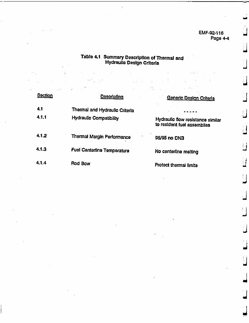
EMF-92-1 16 Page 4-4
Table 4.1 Summary Description of Thermal and Hydraulic Design Criteria
Description
Thermal and Hydraulic Criteria
Hydraulic Compatibility
Thermal Margin Performance
Fuel Centerline Temperature
Rod Bow
Generic Desion Criteria
Hydraulic flow resistance similar to resident fuel assemblies
95/95 no DNB
No centerlne melting
Protect thermal limits
Section
4.1
4.1.1
4.1.2
4.1.3
4.1.4
EMF-92-116 Page 5-1
5.0 NUCLEAR DESIGN ANALYSIS
The nuclear design analyses are subdivided Into two parts: a nuclear fuel assembly design analysis and a core design analysis. The fuel bundle nuclear design analysis is assembly
specific and changes only as features affecting the nuclear characteristics of the fuel change, I.e., rod enrichments, burnable absorber content, etc. The core nuclear design analysis Is specific to the core configuration and changes'on a cycle basis. Nuclear fuel and core analyses are performed using NRC approved methodology" to assure that the new fuel assembly and/or
design features meet the nuclear design criteria eaablished for the fuel and core.
The fuel bundle nuclear design characterisi~cs are considered for each SPC fuel bundle design added to the core. The key characteristics affecting the nuclear design analysis include the
following items:
0 Assembly average enrichment;
* Radial and axial enrichment distribution; and
• Burnable poison content and distribution.
These key characteristics establish the fuel (local) and core power distributions and the kinetic
parameters which are used In the thermal hydraulic, mechanical, and nuclear safety evaluations. The key neutronic design characteristics are selected such that fuel design limits are not exceeded during either normal operation or anticipated operational occurrences, and that the
effects of postulated reactivity accidents will not cause significant damage to the reactor coolant pressure boundary or impair the capability to cool the core. These fuel assembly characteristics are evaluated on a reload cycle specific basis during the neutronic and thermal hydraulic safety
analyses.
The core nuclear characteristics are evaluated during the core design analysis. These analyses
include evaluation of the power distributions, kinetic parameters, control rod worths, etc. These
EMF-92-116 & Page 5-2
4 characteristics (summarized in Table 5.1) are calculated for the reference core loading configuration for each operating cycle. J
5.1 Power and Exposure Histories J
The peaking limits are verified for each fuel design In each reactor. The power histories are J generated using an approved SPC three-dimensional core simulator code. Several histories are provided for the mechanical design; the histories for the rods which would see the peak power in each indMdual cycle and the history for the maximum exposure rod. For example, if a rod was designed for four cycles of operation before reaching the design exposure, there could be up j to five, power histories used In the mechanical design to represent the limiting powers and exposure. For particular analyses, these power histories would then be augmented by the j amount needed to raise the single highest power rod in any of the power histories to the Technical Specification limit.
5.2 Kinetic Parameters
Design criteria for the reactivity coefficients are as follows:
* Doppler Coefficient shall be negative at all operating conditions;
S ' Power Coefficient shall be negative at all operating power levels relative to hot zero power;
• Moderator Temperature Coefficient shall be in accordance with the plant specific Technical Specifications.
Design of fuel assemblies such that less moderation and/or higher temperatures reduce the reactivity of the core results in an automatic shutdown mechanism. Thus, prompt critical J reactivity Insertion events such as the control rod withdrawal accident have an Inherent shutdown
mechanism..
EMF-92-116 Page 5-3
5.3 Control Rod Reactivity
The design of the assembly shall be such that the Technical Specification shutdown margin will
be maintained. Specifically, the assemblies and the core must be designed to remain subcritical
with the highest reactivity worth control rod fully withdrawn and the remaining control rods fully
Inserted. Shutdown margin Is calculated and demonstrated at BOC (as a minimum) for each
reactor.

EMF-92-1 16, Page 5-4
Table 5.1 Summary Description of Nuclear Design Criteria
I Description
Power Distribution
Kinetic Parameter Doppler Reactivity Coefficient Power Coefficient Moderate Temperature Coefficient
Control Rod Reactivity
Generic Design Criteria
In accordance with Technical Specification
Negative Negative relative to HZP In accordance with Technical Specification
Technical Specification - Margin Maintained
Section
5.1
5.2
5.3
'J
-J
J
4
J
j
j
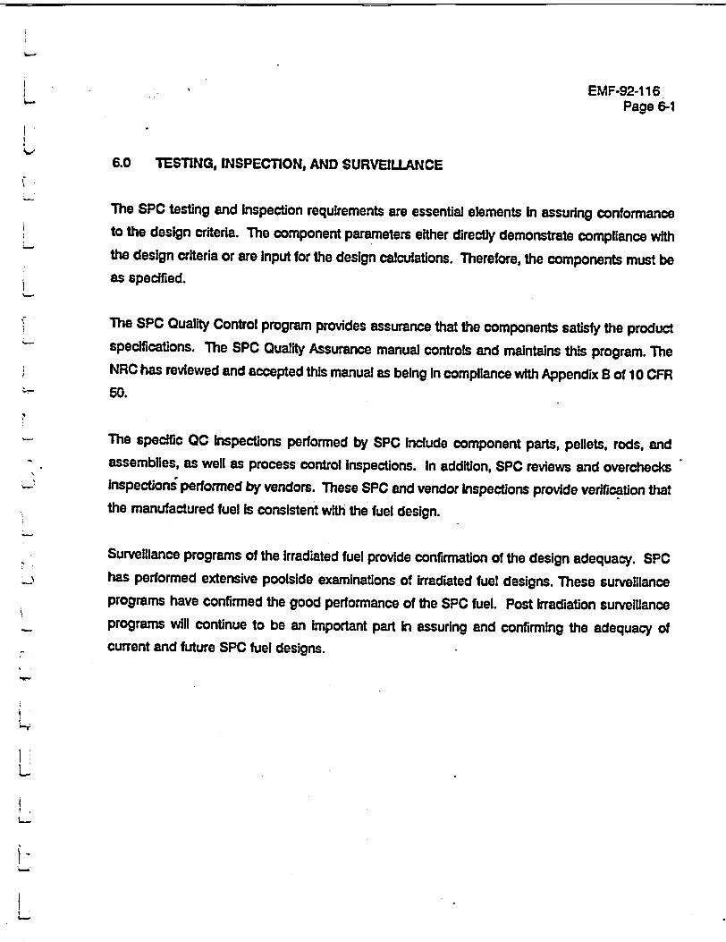
EMF-92-116 Page 6-1
6.0 TESTING, INSPECTION, AND SURVEILLANCE
The SPC testing and Inspection requirements are essential elements in assuring conformance to the design criteria. The component parameters either directly demonstrate compliance with the design criteria or are input for the design calculations. Therefore, the components must be as specified.
The SPC Quality Control program provides assurance that the components satisfy the product specifications. The SPC Quality Assurance manual controls and maintains this program. The NRC has reviewed and accepted this manual as being In compliance with Appendix B of 10 CFR
50.
The specific 0C inspections performed by SPC Include component parts, pellets, rods, and assemblies, as well as process control Inspections. In addition, SPC reviews and overchecks Inspections performed by vendors. These SPC and vendor Inspections provide verification that the manufactured fuel is consistent with the fuel design.
Surveillance programs of the Irradiated fuel provide confirmation of the design adequacy. SPC has performed extensive poolside examinations of Irradiated fuel designs. These surveillance programs have confirmed the good performance of the SPC fuel. Post irradiation surveillance programs will continue to be an important part in assuring and confirming the adequacy of current and future SPC fuel designs.
EMF-92-116 Page 6-2
.4
• j
This page Intentionally left blank.
EMF-92-1 16 Page 7-1
7.0 SAMPLE CALCULATION RESULTS
This section of the report illustrates the application of the design criteria. Also, this section provides typical results from a design calculation. The illustrative design Is a representative 15x1 5 PWR design. The plant specific input and Technical Specification limits are typical of this
design.
Table 7.1 shows the fuel assembly component attributes. Appendix A provides typical nonproprietary component drawings. Tables 7.2 and 7.3 provide the results of the design calculations for the example fuel design. These results reference the respective paragraph in Section 3.0 describing the criteria. Table 7.4 shows typical design duty cycles for the fatigue analysis. The Technical Specification LHGR peaking limit and power history Input is typical of those used In previously approved analysis. This Information In conjunction with the methods described In References 1 and 2, allows the calculation of the fuel assembly behavior. The remaining tables and figures are design results referenced in Tables 7.2 and 7.3.
These results Illustrate typical calculational results for a PWR fuel design. When applied for future
designs, similar calculations would be performed.
This PWR design has been extensively irradiated and has demonstrated excellent In-reactor performance. The Irradiation experience supports the conclusion that the SPC design criteria
provide assurance of the fuel design throughout its design life.
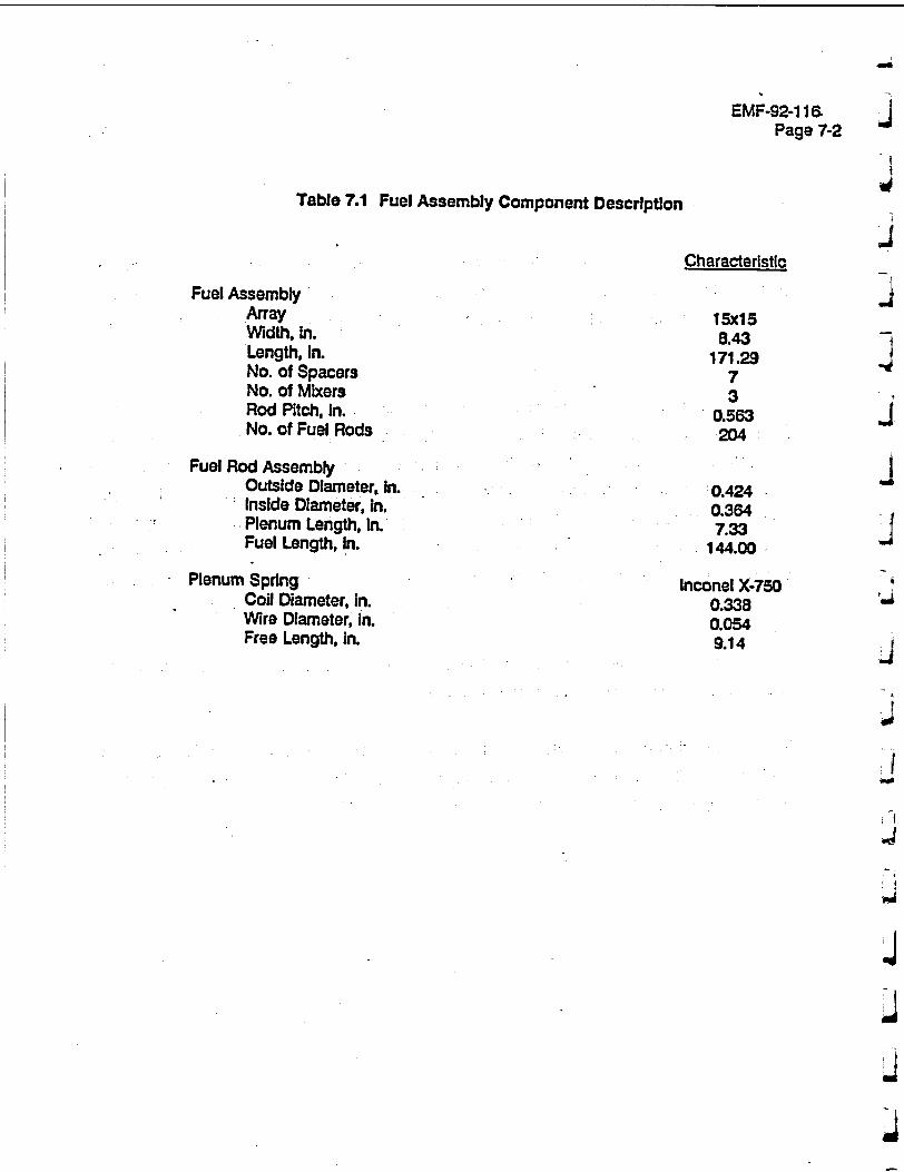
EMF-92-116. Page 7-2
Table 7.1 Fuel Assembly Component Description
Characteristic
Fuel Assembly Array Width, In. Length, In. No. of Spacers No. of Mixers Rod Pitch, In. No. of Fuel Rods
Fuel Rod Assembly Outside Diameter, in. Inside Diameter, In. Plenum Length, in. Fuel Length, In.
Plenum Spring Coil Diameter, in. Wire Diameter, In. Free Length, in.
15x15 8.43
171.29 7 3
0.563 ý204
0.424 0.364 7.33
144.00
Inconel X-750 0.338 0.054 9.14
j
I
J
ii
J
tJ
0'
I �1
4
j
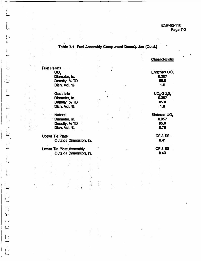
EMF-92-116 Page 7-3
Table 7.1 Fuel Assembly Component Description (Cont.)
Characteristic
Fuel Pellets uo2 Diameter, in. Density, % TD Dish, Vol. %
Gadolinla Diameter. In. Density, % TD Dish, Vol. %
Natural Diameter, In. Density, % TD Dish, Vol. %
Upper Tie Plate Outside Dimension, in.
Lower Tie Plate Assembly Outside Dimension, In.
Enriched UO2 0.357 95.0 1.0
UO2-Gd203 0.357 95.0 1.0
Sintered U02 0.357 95.0 0.75
CF-3 SS65 8.41
CF-3 SS 8.43
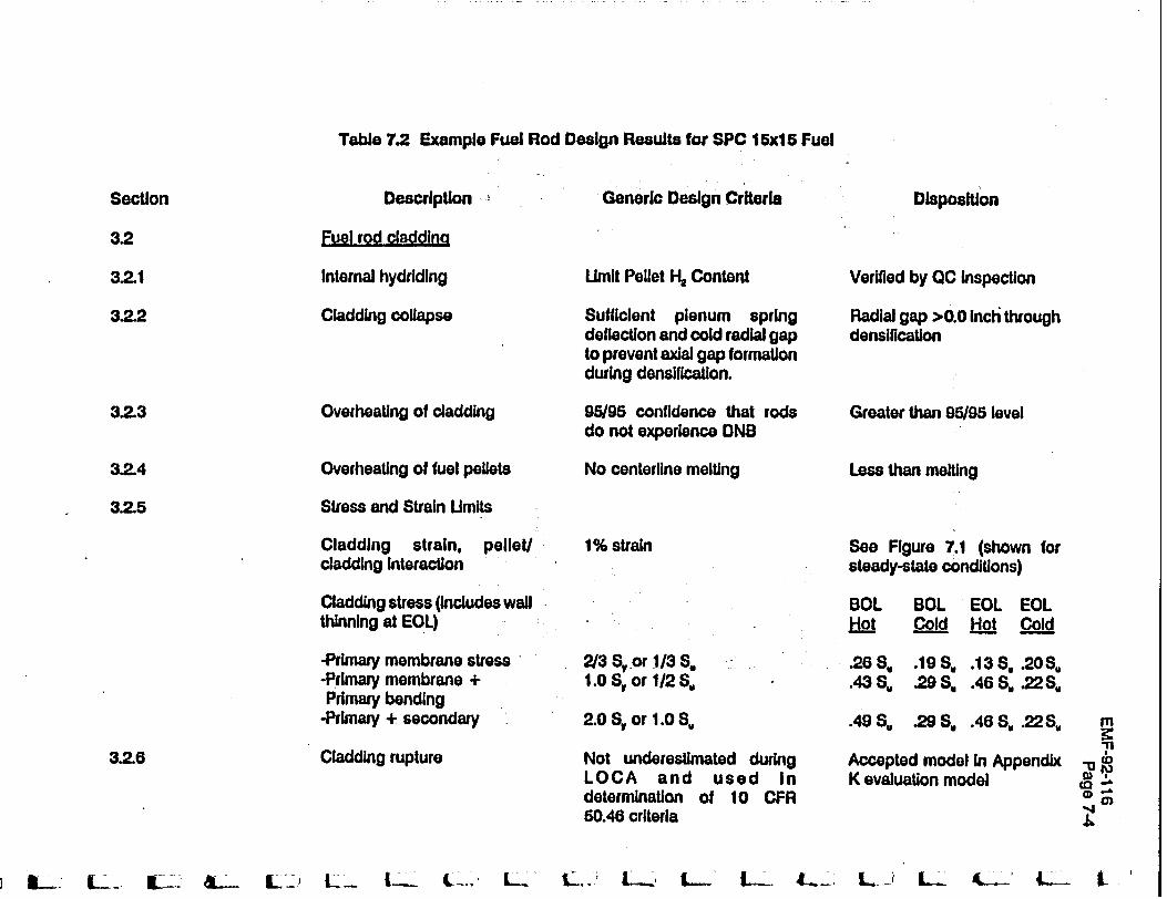
Table 7.2 Example Fuel Rod Design Results for SPC 15x15 Fuel
Section
3.2
3.2.1
3.2.2
3.2.3
3.2.4
3.2.5
3.2.6
Description
Fuel rod claddina
Internal hydriding
Cladding collapse
Overheating of cladding
Overheating of fuel pellets
Stress and Strain Umlts
Cladding strain, pellet/ cladding interaction
Cladding stress (includes wall thinning at EOL)
-Primary membrane stress -Primary membrane + Primary bending
-Primary + secondary
Cladding rupture
Generic Design Criteria
Umit Pellet H. Content
Sufficient plenum spring deflection and cold radial gap to prevent axial gap formation during densification.
95/95 confidence that rods do not experience DNB
No centerline melting
1% strain
2/3 S, or 1/3 S,
1.0 6, or 1/2 S,
2.0 S. or 1.0 S.
Not underestimated during LOCA and used in determination of 10 CFR 50.46 criteria
SL_.'~ L..__ IL-. &ý. ILu_ L_.. L_.. ., Lý .' L L. L. L w L. i L
Disposition
Verified by OC Inspection
Radial gap >0.0 Inch through denslilcation
Greater than 95/95 level
Less than melting
See Figure 7.1 (shown for steady-state conditions)
BOL BOL EOL EOL Hot C ol t Col_._d
.268. .19S. .13 S .20S.
.438. .29S, .46S..22S.
.498, .29S. .46S,.22S.
Accepted model in Appendix K evaluation model
"111 ,.4 KD
"(0 .Q

l-�--, [� F1 f' f7 U - (��7 f-.� f��L 1-- r�
Table 7.2 Example Fuel Rod Design Results for SPC 15x15 Fuel (Cont.)
Description Generic Design Criteria
Fuel rod cladding (cont.)
Mechanical Fracturing Limits ASME Section III, App. F As 8sr
Densification and Swelling Section 3.2.4, 3.2.5.1, and M3.3.7 fm
Disposition
sembly characteristics nOtar to co-resident fuel
)del Included In accepted Il performance codes
Section
3.2
3.2.7
3.2.8
m "1C
fl.
[•- { .... ( . ... (, .. .... I-.... ... ( --•
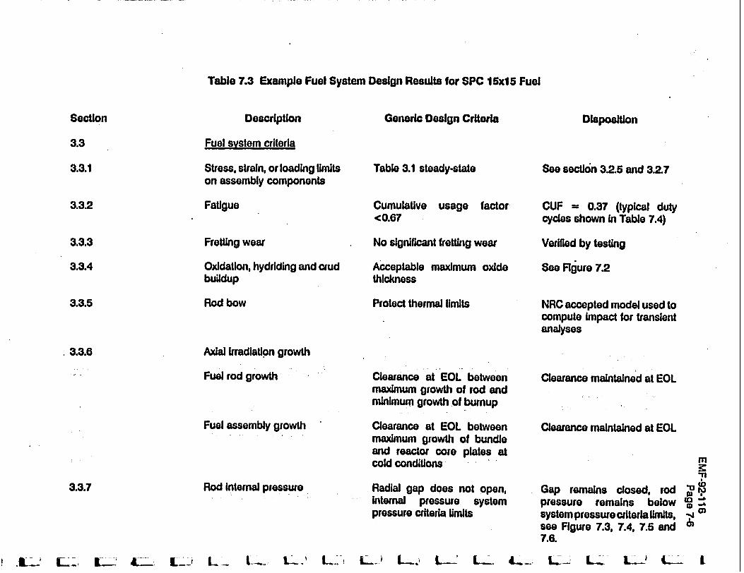
Table 7.3 Example Fuel System Design Results for SPC 15x15 Fuel
Description Generic Design Criteria Disposition
Fuel system criteria
Stress, strain, or loading limits on assembly components
Fatigue
Table 3.1 steady-state
Cumulative <0.67
Fretting wear
Oxidation. hydriding and crud buildup
Rod bow
Axial Irradiation growth
Fuel rod growth
Fuel assembly growth
Rod Internal pressure
usage factor
No significant fretting wear
Acceptable maximum oxide thickness
Protect thermal limits
Clearance at EOL between maximum growth of rod and minimum growth of burnup
Clearance at EOL between maximum growth of bundle and reactor core plates at cold conditions
Radial gap does not open, Internal pressure system pressure criteria limits
Seo section 3.2.5 and 3.2.7
CUF = 0.37 (typical duty cycles shown In Table 7.4)
Verified by testing
See Figure 7.2
NRC accepted model used to compute impact for transient analyses
Clearance maintained at EOL
Clearance maintained at EOL
Gap remains closed, rod pressure remains below system pressure criteria limits, see Figure 7.3, 7.4, 7.5 and 7.6.
L- L . I t-' -! LL L- L ) L..ý L.- L- 4,.. -.. L L"L LL
Section
3.3
3.3.1
3.3.2
3.3.3
3.3A
3.3.5
.3.3.6
3.3.7
m "11
9 WI
D -A
L--1 L- I.I.AL-' Lý-- tý- L: L_ L--
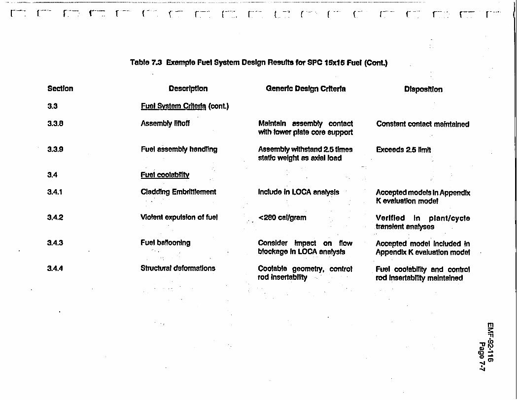
Table 7.3 Example Fuel System Design Results for SPC I Sx 5 Fuel (Cont.)
Description Generic Design Criteria
Fuel System Criteria (cont.)
Assembly liftoff Maintain assembly contact Cor with lower plate core support
Fuel assembly handling Assembly withstand 2.5 times Exo static weight as axial load
Fuel coolabillty
Cladding Embrittlement Include In LOCA analysis Ace K m
Violent expulsion of fuel <280 callgram Ver tran
Fuel ballooning Consider Impact on flow Aco blockage In LOCA analysis App
Structural deformations Coolabie geometry, control Fuelrod Insertabitity rod
DispositionSection
3.3
3.3.8
3.3.9
3.4
3.4.1
3.4.2
3.4.3
3.4.4
(�7 (.
istant contact maintained
eds 2.5 limit
opted models In Appendix valuation model
Ifled In plantlcycle slent analyses
opted model Included In endix K evaluation model
I coolabllity and control Insertability maintained
m '11
0..r ,-
( F -- .-. -, - V

EMF-92-1 16
Page 7-8
Table 7.4 Duty Cycles
Desiqn Duty Cycles: The number of operational cycles over the expected lifetime of the fuel assembly:
1. Current and Anticipated Practice
a. Weekly valve operating test 100% to 70% J hold @ 70% for 2.5 hours 70% to 100% @ a specified maneuvering rate .J
b. Twice/month steam generator leakage test 100% to hot standby hold @ hot standby for one day hot standby to 30% hold @ 30% for 0.5 hour 30% to 100% @ a specified maneuvering rate
c. One/B months steam generator Inspection 100% to 0 power 3 cold for one week 0 power to 30% hold @ 30% for 0.5 hour 30% to 100% @ a specified maneuvering rate
2. Load Follow J 100% to 50% to 100% @ a specified maneuvering rate. - /day
3. Arbitrary Cycles
a. 10 scrams/year b. step load decrease of 95% - 2/year c. step load Increase from 0 power to 30% - 2/year d. step load Increase of 20% power- 1/week e. 30% to 100% @ a specified maneuvering rate - 2/year
!j
EMF-92-116 Page 7-9
Figure 7 .i AO0 Total Uniform Strain
Strain Analysis: Maximum CorrosionFigure 7.2
I
EMF-92-116 Page 7-10
Figure 7.3 Strain Analysis: Clad Creepdown
J j
a"
j
J
F- J
I
I I I I k d
, !
EMF-92-116 Page 7-11
F I 7 Figure 7.4 Gas Pressure Analysis: Fission Gas Release K
Figure 7.5 Gas Pressure Analysis: Gas PressureI
EMF-92- 6 1 Page 7-12
J
j
I~i Figure 7.6 Gas Pressure Analysis: Fuel Temperature
kj
J
1,4
d
EMF-92-116 Page 8-1
L 8.0 REr.RENCES
1. XN-NF-82-06(A), Rev.1, & Supplements 2, 4, & 5, "Qualification of Exxon Nuclear Fuel for Exended Bumup," Exxon Nuclear Co., Oct. 1986.
2. ANF-88-133(A) and Supplement 1, "Qualification of Advanced Nuclear Fuels' PWR Design Methodology for Rod Bumup of 62 GWd/MTU', Advanced Nuclear Fuels Corporation, December 1991.
3. ANF-89-060(A) and Supplement 1, "Generic Mechanical Design Report High Thermal Performance Spacer and Intermediate Row Mixeru, Advanced Nuclear Fuels Corporation, May 1991.
4. NUREG-0800, Rev. Z 'Standard Review Plan for the Review of Safety Analysis Reports for Nuclear Power Plants, LWR Edition," U. S. Nuclear Regulatory Commission, July 1981.
5. EMF-1 (A), "Quality Assurance Manual," Siemens Power Corporation.
6. Code of Federal Regulations, Title 10, "Energr, Part 50, Appendix K, "ECCS Evaluation Models'.
7. NUREG 0630, "Cladding Swelling and Rupture Models for LOCA Analysis," U. S. Nuclear Regulatory Commission, April 1980.
8. Code of Federal Regulations, Title 10, "Energy", Part 50.46, "Acceptance Criteria for Emergency Core Cooling Systems for Ught Water Nuclear Power Reactors."
9. ASME Boiler and Pressure Vessel Code, Section 111, "Rules for Construction of Nuclear Power Plant Components', 1977.
10. Swanson Analysis System, "ANSYS-Engineering Analysis System Theoretical Manual," 1977, and "ANSYS-User's Guide, 1979.
11. O'Donnell, W.J. and Langen, B.F., *Fatigue Design Basis for Zircaloy Components', Nuclear Science and Enqineerina, 20:1.
12. XN-NF-621 (A), Rev. 1, "Exxon Nuclear DNB Correlation for PWR Fuel Designs', Exxon Nuclear Company, September 1983.
13. ANF-1 224(A), "Departure from Nucleate Boiling Correlation for High Thermal Performance Fuel", Advanced Nuclear Fuels Corporation, March 1990.
14. XN-75-27(A), and Supplements 1,2, 3, and 4, "Neutronlc Design Methods for Pressurized "Water Reactors", Exxon Nuclear Company, main report issued April 1977.
U
EMF-92-1 1 6 Page A-1
Appendix A - Fuel Assembly romponent Drawings
Description
EMF-SK-30.,558, Rev. 0 Fuel Bundle Assembly
EMF-SK-02560, Rev. 0 Fuel Rod Assembly
EMF-SK-302,559, Rev. 0 "Spacer Assembly"
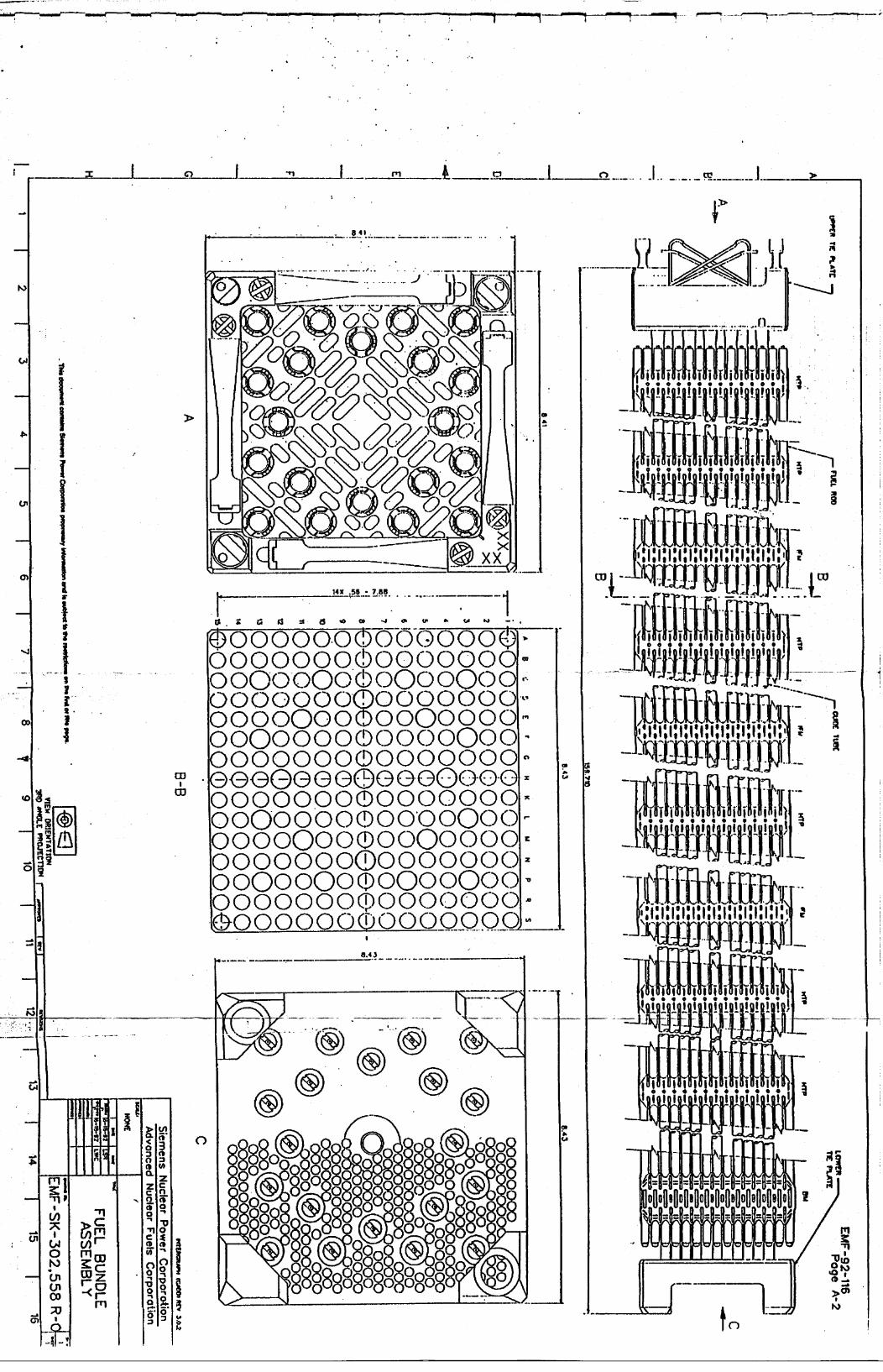
14X .55 7.86
. OOOOOOOO |
t
I I 11 T I I I aI
I I
I S I
3. I
z z
K
IA
I-
10
13A
i ar i *.,
ie IsI. mI
ý
jj a0E1J a00iiirir1L
oc 01¶ 1
a
I.'
÷oo~ooQo~ooQoooo O0000000000000 oo~oo~o~ooo~oo
OO©OOOOO®OOOOOOO 000000000000OOO @@@GG@@e@@OOO-O0-OOOQOOOOO®OOOOOOO oo~oooo®ooooooO oooo~ooQooQoooo 0000000000000
oo0oo0oo00o0ooO ~ooooooorooooooo
14-
ED
83
1 � -
____AL....__ 0
I
V
I
.4
lq-- 11I.
W
I
T n•
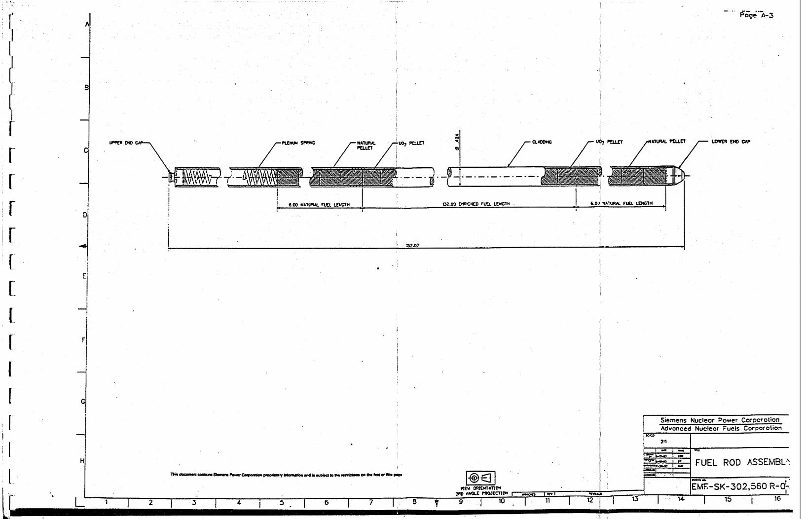
II
I17
71*d- "emu ~f~ S4- Aft- Pews C om i.ppv~watw hftom 8-din "Mm alogo ~~i C ' W ~toP9
VIEW ORIENTATMO' wn ONCI PROn.WVIOflI - ,
C5 A = in- pii I ilI 1
21 4j -5 - Iý -6 7 V
Siemens Nuclear Power Co!rpor o4,on Advanced Nuclear Fuels Corporotion
291
FUEL ROD ASSEr-MBL\
_______EMF-SK-302,560 R-Oj-
I - -4- 1 ý15 1 715
APoge A-3
WLOWEND CAP~I
9
LIPPER 0DO
Cl
0
LIL
El
C
HI
1
M.= -M
I I-10 1 11 1 lz---- T

EMF-92-116 Page A-4
0J
VIEW ORIENTATION 3M ANGLIE PROJECTION
Siemens Nuclear Power Corporoation Advanced Nuclear Fuels Corporotion
b~1-17-92 ISR
SPACER ASSEMBLY
EMF-SK-302.559 R-o-
A
C
C
E4
F
C
HI
!
EMF-92-116 Issue Date: 8/3/92
Generic Mechanical Design Criteria
for PWR Fuel Designs
Distribution
CA Brown GJ Busselman
RA Copeland (25) RJ DeSteese U Federico
DE Hershberger "TIM Howe A Reparaz
HE Williamson PWR Fuel Engineering (35)
Fuel Design (10) Document Control (5)


![TOPIC: 192004 KNOWLEDGE: K1.01 [3.1/3.2] QID: P133...NRC Generic Fundamentals Examination Question Bank--PWR November 2019-1- Reactivity Coefficients TOPIC: 192004 KNOWLEDGE: K1.01](https://static.fdocuments.net/doc/165x107/60d8d67d9d74587fe765ad25/topic-192004-knowledge-k101-3132-qid-p133-nrc-generic-fundamentals.jpg)


![TOPIC: 193006 KNOWLEDGE: K1.04 [3.4/3.6] QID: P78 · NRC Generic Fundamentals Examination Question Bank--PWR February 2017-1- Fluid Statics and Dynamics . TOPIC: 193006 . KNOWLEDGE:](https://static.fdocuments.net/doc/165x107/5adc4ee37f8b9a213e8b5d4a/topic-193006-knowledge-k104-3436-qid-p78-generic-fundamentals-examination.jpg)