![VDOT CONSTRUCTION CONTRACT CLAIMS · 2019-09-10 · o 6 claims resolved by State Construction Engineer [Step 1 in 2-Step Claims Process] o 3 claims resolved by Deputy Commissioner](https://static.fdocuments.net/doc/165x107/5e8eb69192128d1a7122c500/vdot-construction-contract-claims-2019-09-10-o-6-claims-resolved-by-state-construction.jpg)
Generic Design Assessment - Westinghouse AP1000 - Step … · or claims specific to chemistry. This...
59
NUCLEAR DIRECTORATE GENERIC DESIGN ASSESSMENT – NEW CIVIL REACTOR BUILD STEP 3 REACTOR CHEMISTRY ASSESSMENT OF THE WESTINGHOUSE AP1000 DIVISION 6 ASSESSMENT REPORT NO. AR 09/035 HSE Nuclear Directorate Redgrave Court Merton Road Bootle Merseyside L20 7HS Health and Safety Executive
Transcript of Generic Design Assessment - Westinghouse AP1000 - Step … · or claims specific to chemistry. This...

NUCLEAR DIRECTORATE
GENERIC DESIGN ASSESSMENT – NEW CIVIL REACTOR BUILD
STEP 3 REACTOR CHEMISTRY ASSESSMENT OF THE WESTINGHOUSE AP1000
DIVISION 6 ASSESSMENT REPORT NO. AR 09/035
HSE Nuclear Directorate Redgrave Court Merton Road Bootle Merseyside L20 7HS
Health and Safety Executive

HSE Nuclear Directorate Division 6 Assessment Report No. AR 09/035
EXECUTIVE SUMMARY
This report presents the findings of the reactor chemistry assessment of the Westinghouse AP1000 Pre-Construction Safety Report (PCSR) and relevant sections of the European Design Control Document (DCD) (Refs 1 and 12) undertaken as part of Step 3 of the Generic Design Assessment (GDA) process.
Scope of Assessment Carried Out
The scope of the reactor chemistry assessment is detailed within the Project Initiation Document and its addendum (Refs 10 and 11).
There was no Step 2 assessment for chemistry and the AP1000 safety case contains no sections or claims specific to chemistry. This report for Step 3 therefore identifies the main chemistry claims implied in various chapters of the PCSR and DCD together with claims made in response to technical queries and at meetings. The information gathered by this process was sufficient to allow consideration of arguments presented by Westinghouse mainly in relation to operational chemistry.
It is important to stress that the Step 3 report represents a progress statement; some areas are not programmed for assessment until Step 4. Not all areas have been assessed to the same extent due to the limited detail of some analyses presented to date.
During Step 3 we raised 11 Technical Queries (TQ) and commissioned contract support to examine the main processes controlling primary circuit chemistry in normal operation.
Conclusions
We were encouraged that Westinghouse has put considerable effort into the chemistry of AP1000 but the principal aspects of the presentation of safety that need improvement are;
1. A topic report or PCSR overview of chemistry (including boron chemistry and faults) will be needed during Step 4.
2. Severe accident chemistry has received significant attention, however some of the analyses appear to be dated and the relevance to AP1000 needs to be established.
3. Chemical behaviour of the Chemical Volume (and control) System (CVS) and other novel, simplified and passive systems will need further justification during Step 4.
4. Zinc dosing and the high duty core will need further justification during Step 4.
As a vendor Westinghouse often leaves operators some scope in respect to site-specific and operational chemistry, including many elements needed for licensing. This could limit the scope of the GDA assessment. We believe many of these are presentational issues, however Westinghouse has;
a) Recently itself identified design changes for specific chemistry aspects of AP1000.
b) No plans to undertake key analyses of secondary circuit safety, at present.
Additional support contracts are being put in place to provide support in reviewing Westinghouse documentation for different chemistry aspects of accidents, fuel, materials and operations. Assessment of the chemistry of fuel and accidents will be coordinated with equivalent fault studies planned to begin in Step 4. The programme for Step 4 allows limited time for assessment of severe accidents.
So far no chemistry-related Regulatory Issues (RI) have been identified and Westinghouse’s readiness to address TQs is encouraging. The possibility of changes to a part of the primary coolant circuit or its ancillaries arising from analyses and assessments during Step 4 cannot be ruled out.
Page (i)

HSE Nuclear Directorate Division 6 Assessment Report No. AR 09/035
LIST OF ABBREVIATIONS
ADS Automatic Depressurisation System
ALARP As Low as Reasonably Practicable
AOA Axial Offset Anomaly (see also CIPS)
BMS (Nuclear Directorate) Business Management System
BOP Balance Of Plant
CCWS Component Cooling Water System
CIPS Crud-Induced Power Shift
CMT Core Make-up Tank
CORS Catalytic Oxygen Reduction System
CoSHH Control of Substances Hazardous to Health (Regulations)
CP Corrosion Product
CPS Condensate Polishing System
CRDM Control Rod Drive Mechanism
CVS Chemical Volume (and control) System
DCD Design Control Document
DSEAR Dangerous Substances and Explosive Atmosphere Regulations
DTS Demineralised Water Transfer System
DWS Demineralised Water System
EA The Environment Agency
EDI Electrodeionisation
EMIT Examination, Maintenance, Inspection and Testing
EPRI Electric Power Research Institute (US)
FAC Flow Accelerated Corrosion
FP Fission Product
GDA Generic Design Assessment
HEPA High Efficiency Particulate Air
HFT Hot Functional Testing
HSE The Health and Safety Executive
HX Heat Exchanger
I600 Inconel 600 alloy
I690 Inconel 690 alloy
IAEA The International Atomic Energy Agency
IGA Inter-granular Attack
IGSCC Inter-granular Stress Corrosion Cracking
IRWST In-containment Reactor Water Storage Tank
IVR In-Vessel Retention
IX Ion Exchange
Page (ii)

HSE Nuclear Directorate Division 6 Assessment Report No. AR 09/035
LIST OF ABBREVIATIONS
LOCA Loss of Coolant Accident
LTCP Low-temperature Crack Propagation
MA Mill Annealed alloy (specifically Inconel 600 or 690)
MTC Moderator Temperature Coefficient
ND The (HSE) Nuclear Directorate
NRC Nuclear Regulatory Commission (US)
NSS Nuclear Sampling System
NSSS Nuclear Steam Supply System
ORE Operator Radiation Exposure
PAR Passive Autocatalytic Recombiner
PASS Post-Accident Sampling System
PCER Pre-construction Environment Report
PCSR Pre-construction Safety Report
PID Project Initiation Document
PRA Probabilistic Risk Assessment
PRHR Passive Residual Heat Removal system
PSR Preliminary Safety Review
PSS Primary (circuit) Sampling System
PWR Pressurised Water Reactor
PWSCC Primary Water Stress Corrosion Cracking
PXS Passive Cooling System
PZR Pressuriser
RCDT Reactor Coolant Drain Tank
RCP Reactor Coolant Pump
RCS Reactor Coolant System
RI Regulatory Issue
RIA Regulatory Issue Action
RNS Residual Heat Removal System
RO Regulatory Observation
ROA Regulatory Observation Action
RP Requesting Party
RPV Reactor Pressure Vessel
RSG Recirculatory Steam Generator
RWST Refuelling Water Storage Tank
SAP Safety Assessment Principle
SCC Stress Corrosion Cracking
SFAIRP So Far as is Reasonably Practicable
Page (iii)

HSE Nuclear Directorate Division 6 Assessment Report No. AR 09/035
LIST OF ABBREVIATIONS
SFP Spent Fuel Pool
SG Steam Generator
SGBS Steam Generator Blowdown System
SGTR Steam Generator Tube Rupture
SINCAD SIlver-INdium-CADmium alloy
SSC System, Structure or Component
SSS Secondary (circuit) Sampling System
TAG (Nuclear Directorate) Technical Assessment Guide
TQ Technical Query
TS Tube Sheet (in SG)
TSC Technical Support Contractor
TSP Tube Support Plate (in SG)
TSP Trisodium Phosphate
TT Thermally Treated alloy (specifically Inconel 600 or 690)
VCT Volume Control Tank
VGB Verenigate Grosskraftwerke Betreiber (Federation of Large Power Station Operators, Germany)
WEC Westinghouse Electric Company LLC
WENRA The Western European Nuclear Regulators’ Association
WGS Waste Gas System
WLS Waste Liquid System
Page (iv)
HSE Nuclear Directorate Division 6 Assessment Report No. AR 09/035
Page (v)
TABLE OF CONTENTS
1 INTRODUCTION...................................................................................................................... 1
1.1 GDA Process..................................................................................................................... 1
1.2 Assessment Methodology ................................................................................................. 1
1.3 Assessment Objectives ..................................................................................................... 2
1.4 Assessment Scope............................................................................................................ 2
2 NUCLEAR DIRECTORATE’S ASSESSMENT ........................................................................ 4
2.1 Requesting Party’s Safety Case........................................................................................ 4
2.1.1 Structure................................................................................................................. 4
2.1.2 Reactor Chemistry Content .................................................................................... 4
2.1.3 Reactor Chemistry Claims...................................................................................... 5
2.2 Standards and Criteria ...................................................................................................... 5
2.2.1 Safety Assessment Principles ................................................................................ 5
2.2.2 Other Nuclear Directorate Guidance ...................................................................... 5
2.2.3 External Standards and Guidance.......................................................................... 5
2.3 Assessment....................................................................................................................... 6
2.3.1 Chemistry Standards.............................................................................................. 6
2.3.2 Start-up and Shutdown Chemistry.......................................................................... 7
2.3.3 Primary Circuit ........................................................................................................ 9
2.3.4 Secondary Circuit ................................................................................................. 25
2.3.5 Fuel Pool Systems ............................................................................................... 31
2.3.6 Waste Treatment Systems ................................................................................... 34
2.3.7 Ancillary Systems ................................................................................................. 34
2.3.8 Accident Chemistry............................................................................................... 35
2.3.9 GDA Assessment Requirements.......................................................................... 39
3 CONCLUSIONS AND RECOMMENDATIONS...................................................................... 42
4 REFERENCES....................................................................................................................... 44
Figure 1: Reactor Chemistry Safety Assessment Principles ‘Mind Map’
Table 1: Design Control Document (Ref. 12) Reactor Chemistry Content
Table 2: Relevant Safety Assessment Principles Considered During Step 3
Table 3: Relevant Technical Assessment Guides Considered During Step 3
Annex 1: Reactor Chemistry – Status of Regulatory Issues and Observations

HSE Nuclear Directorate Division 6 Assessment Report No. AR 09/035
1 INTRODUCTION
1 This report presents the findings of the reactor chemistry assessment of the Westinghouse AP1000 Pre-Construction Safety Report (PCSR) (Ref. 1) undertaken as part of Step 3 of the Health and Safety Executive (HSE) Generic Design Assessment (GDA) process. This assessment has been undertaken in line with the requirements of the Business Management System (BMS) document AST/001 (Ref. 2) and its associated guidance document G/AST/001 (Ref. 3). AST/001 sets down the process of assessment within the Nuclear Directorate (ND) and explains the process associated with sampling of safety case documentation. The Safety Assessment Principles (SAP) (Ref. 4) have been used as the basis for the assessment of reactor chemistry associated with the AP1000 design. The SAPs require that reactor chemistry on a nuclear power plant be identified and considered in safety assessments. Ultimately, the goal of assessment is to reach an independent and informed judgment on the adequacy of safety in the generic design.
1.1 GDA Process
2 The HSE and the Environment Agency (EA) developed the GDA process in response to a request from the Government following its 2006 Energy Review (Ref. 5). In summary, HSE and EA proposed that new nuclear power stations should be subject to a methodical, defined, multi stage assessment and licensing/permitting process, which includes an assessment process for generic designs.
3 Subsequently, the nuclear regulators published a suite of guidance material on GDA for new nuclear power station designs (in January 2007 and August 2008) which led to a number of companies asking to participate in GDA.
4 The GDA process splits the ND assessment into 4 steps and 15 assessment areas, one area being reactor chemistry. Overall, Steps 1 and 2 have been completed (but not for reactor chemistry expressly) and reported previously (Ref. 6) and ND has completed Step 3 of GDA, which has led to the production of this reactor chemistry assessment report. GDA Step 3 is defined as an ‘overall design safety review’. The overall ND description and aims for Step 3 (and the other steps) are given in the GDA guidance material (Ref. 7).
5 GDA Step 3 is not a complete assessment. Implicit in this description and aims of GDA is that it is expected that assessment of the design will continue in GDA Step 4. This is defined as a ‘detailed design assessment’ and will provide an in-depth assessment of the safety case and generic site envelope (Ref. 7). To put these aims into context of a UK safety submission, Step 3 represents assessment of the ‘arguments’ and Step 4 represents the ‘evidence’ stage of a structured ‘claims - arguments - evidence’ safety case.
1.2 Assessment Methodology
6 As stated previously (para. 1) this report has been prepared in accordance with relevant ND guidance (Ref. 8 and 9), which also informs the methodology used, namely a sampling basis, dictated by consideration of risk and hazard significance, in coordination with the other assessment disciplines and the scope defined in the Project Initiation Document (PID) (Ref. 10).
7 The Step 3 assessment process consists of examining the arguments and identifying the evidence in Requesting Party (RP) submissions relevant to reactor chemistry. These are then assessed against the expectations and requirements of the SAPs and other guidance considered appropriate. Further details on the information that supported this assessment are given in Section 2.2 of this report.
Page 1
HSE Nuclear Directorate Division 6 Assessment Report No. AR 09/035
8 The basis of the assessment undertaken to prepare this report is therefore;
Reading the appropriate chapters of the RP’s PCSR and DCD submission.
Consideration of internal and international standards and guidance.
Consideration of international experience, operational feedback and expertise.
Consideration of assessments performed by other regulators, especially their findings.
Interaction with other relevant technical areas (where available).
Following the GDA interface arrangements (Ref. 7); raising and issuing of Technical Queries (TQ), Regulatory Observations (RO) as appropriate, followed by assessment of RP responses.
Holding the necessary technical meetings to progress TQ resolution.
9 Consistent with the GDA deadlines and to provide ND with information for use in our assessment of reactor chemistry in AP1000, we have initiated a significant programme of work involving a number of Technical Support Contractors (TSC). This external work programme is just beginning and has already provided seminars for several ND staff. Some initial feedback from the programme has been included in this report. The programme of TSC support will increase during Step 4.
1.3 Assessment Objectives
10 In line with the generic aims for Step 3 (Ref. 7), the following general objectives have informed the assessment for reactor chemistry;
Improve ND knowledge of the design.
Identify significant issues.
Identify whether any significant design or safety case changes may be needed.
Identify major issues that may affect design acceptance and attempt to resolve them.
Achieve a significant reduction in regulatory uncertainty.
11 Timely and appropriate input to each of these activities was also considered as an objective during the assessment process. The assessment resulted in this assessment report (effectively a progress statement) prepared against the defined assessment scope for reactor chemistry in Step 3 which concludes on the adequacy or otherwise of the reactor chemistry of the generic design.
12 This assessment report is a principal output from Step 3. This report will be used by ND to produce a cross-discipline project assessment report of the reactor design at the end of Step 3, taking into account the findings from the other assessment areas.
1.4 Assessment Scope
13 As indicated previously, para. 6, prior to instigation of the Step 3 assessment a PID (Ref. 10) was prepared which defined the scope of the assessment of reactor chemistry. Part way through Step 3 an addendum to this PID (Ref. 11) was prepared which accounted for an increased ND resource. Together these documents formed the basis for the subsequent assessment.
14 In order to understand the scope of the assessment conducted, it is first sensible to consider the definition of reactor chemistry that has been applied during this assessment such that the boundaries are clearly stated. For the purpose of this assessment reactor chemistry was taken to be;
Page 2
HSE Nuclear Directorate Division 6 Assessment Report No. AR 09/035
"the chemistry of the design including the effects of coolant chemistry on reactivity, pressure boundary integrity, fuel and core component integrity, fuel storage in cooling pools, radioactive waste generation and radiological doses to workers"
15 Thus, reactor chemistry is principally concerned with five main areas; reactivity control, protection of the structural materials (specifically related to integrity of the pressure boundaries), maintaining fuel integrity and safety performance, minimisation of out of core radiation fields and releases during accident conditions. The relative influence each of these can have on safety can vary depending upon the system under assessment; however these main areas were considered throughout.
16 Historically, reactor chemistry was a poorly controlled parameter in early Pressurised Water Reactors (PWRs) which gave rise to a number of safety issues related to structural integrity, fuel damage and high radiation fields as might be expected. Subsequently, recognition of the importance of a properly controlled chemistry led to great improvements in each of these areas and modern PWRs would be expected to operate under a regime where due consideration has been given to each of these aspects.
17 In line with the PID, the assessments of reactor chemistry during Step 3 has concentrated on chemical processes that;
May cause an uncontrolled variation in core reactivity.
May threaten the containment of nuclear matter.
Contribute to operator radiation exposure.
Generate radioactive waste and discharges.
Determine source terms for severe accident analysis.
18 Due to the nature of the GDA process, it was not considered feasible or realistic for the RP’s to be able to fully define the chemistry that may be used at this stage. As such, detailed site specific aspects and commissioning are excluded from the assessment during this step and are to be considered during Phase 2 (licensing). However, it is considered appropriate to regard these aspects in more general terms during Step 3 (and Step 4) especially where it is deemed appropriate that the RP must demonstrate the capability of the design to accommodate the likely range of operating chemistry regimes or conditions, and cope with deviations from normal chemistry without ‘cliff edge’ effects.
19 Reactor chemistry is an area which interacts with a number of other GDA technical assessment disciplines. Principal amongst these are the radiation protection, structural integrity, radwaste and fault studies areas where chemistry can have a direct impact on safety. For the same reasons reactor chemistry is of interest to the EA as part of their assessment processes; however, this does not preclude interaction with the other areas. For all the disciplines there is significant and appropriate coordination between technical areas to ensure that the regulatory effort is proportionate and targeted.
20 It should be noted that reactor chemistry was not an assessment area during Step 2 and assessment did not start at the outset of Step 3. This means that the assessment for reactor chemistry is not as progressed as some of the other technical disciplines considered, but this can be recovered in Step 4. Specifically for Step 3, this meant that the Step 2 assessment had to be effectively incorporated into the Step 3 scope. It is also worth noting that none of the other disciplines assessed during Step 2 raised any issues related to reactor chemistry during their Step 2 assessment work.
Page 3
HSE Nuclear Directorate Division 6 Assessment Report No. AR 09/035
2 NUCLEAR DIRECTORATE’S ASSESSMENT
2.1 Requesting Party’s Safety Case
2.1.1 Structure
21 The UK AP1000 PCSR (Ref. 1) is described as the ‘top-tier’ document within the Westinghouse safety submission for GDA and as such contains the claims and arguments of the safety case, indicating the location of the supporting evidence. This document was produced specifically as part of the Westinghouse GDA submission.
22 The PCSR claims that most of the evidence for the claims and arguments can be found within the European AP1000 Design Control Document (DCD) (Ref. 12). This document has been adapted from one produced for the US licensing process for AP1000 and was essentially formatted, with only minor changes, to become part of the UK GDA submission. The European DCD is essentially identical to Revision 17 of the US DCD.
23 Although a number of other documents are present in the Westinghouse submission, and do contain useful information, together the PCSR and DCD represent the bulk of the safety case.
24 The structure of the PCSR does not relate directly to the corresponding structure of the DCD and as such it is not straightforward to transfer directly between the two documents. We believe this is a consequence of the nature of the safety case presented for AP1000, which is structured from the DCD up rather than from the PCSR down. Overall this has had a negative impact on the reactor chemistry assessment of AP1000.
2.1.2 Reactor Chemistry Content
25 Neither the PCSR nor the DCD contain any main sections which deal with reactor chemistry as a whole for the design. This is perhaps not unexpected, due to the nature of reactor chemistry and the many interactions it has with systems, structures and components throughout the entire plant. Instead reactor chemistry is detailed within the text for specific individual systems, principally within the DCD.
26 This is exemplified in Table 1 which details the sections of the DCD relevant to reactor chemistry. For the significant systems of interest to the reactor chemistry assessment, information is scattered widely throughout the DCD.
27 Although we were encouraged that the chemistry of severe accidents has been considered and is presented in the DCD, some of the analysis may be dated and the relevance to AP1000 will need to be established.
28 Similarly, Westinghouse has provided some information on the secondary circuit components and systems, however they did not intend to supply some of the more relevant analysis for these systems to ND during GDA and hence they are not included in the PCSR or DCD.
29 These factors have had a negative impact on the reactor chemistry assessment of AP1000.
30 It should be recognised that at present the PCSR and DCD together do not represent a complete safety case in a UK context, especially from a reactor chemistry perspective. It is expected that a number of other documents would be required to fully substantiate the ‘evidence’ stage of the assessment; these could include such items as ‘design specifications’ or ‘assessment reports’. By their very nature these documents would not form part of a PCSR, but should be referenced as appropriate as they are an important part of the overall safety case. At this stage, the complete suite of documents is not needed (and in fact some will not yet be available), however a number of these will be required in GDA Step 4.
Page 4

HSE Nuclear Directorate Division 6 Assessment Report No. AR 09/035
2.1.3 Reactor Chemistry Claims
2.1.3.1 Pre-construction Safety Report
31 Despite the PCSR claiming to provide the ‘claims and arguments’ for the AP1000 design there are only 9 explicit claims made throughout the entire document (Ref. 1, Section 1.4). Although these claims are reasonable, they are all pitched at a very high level and are not expressly related to reactor chemistry (although they could be readily interpreted to a reactor chemistry context if desired). Most claims in the PCSR are made implicitly.
2.1.3.2 Design Control Document
32 Due to its origin as a means of demonstrating to the US Nuclear Regulatory Commission (NRC) compliance with US law, the DCD would not be expected to have any explicit claims presented in a manner compatible with UK requirements and this proved to be the case. Most claims in the DCD are made implicitly.
2.2 Standards and Criteria
33 The following section outlines the relevant standards and criteria that have informed the reactor chemistry assessment.
2.2.1 Safety Assessment Principles
34 Of all of the standards and criteria that have informed the assessment, it is the selection of the relevant SAPs that plays a key role in determining the scope of any assessment in ND. These were defined in the PID (Ref. 10) and are given in Table 2. These SAPs are focussed on the functions and systems leading to the largest hazards or risk reduction.
35 Also included within the PID (Ref. 10) was a ‘mind map’ for the relevant SAPs. This is a pictorial representation of how the SAPs interact with the reactor chemistry assessment and is also useful in understanding the holistic nature of the subject. This is reproduced in Figure 1.
2.2.2 Other Nuclear Directorate Guidance
36 Assessment has been conducted to relevant ND internal standards and guidance (Refs 2, 3, 8 and 9). In addition, the ND Technical Assessment Guides (TAGs) have informed the assessment. Those relevant to the reactor chemistry assessment are given in Table 3.
37 Although not part of the formal assessment, a brief review of documents relating to the permissioning of Sizewell B was conducted to provide background information and guidance on the levels of assessment applicable for this and subsequent Steps of GDA.
2.2.3 External Standards and Guidance
38 External standards and guidance specific to reactor chemistry are very limited in number.
39 The International Atomic Energy Authority (IAEA) has prepared a standard on reactor chemistry (Ref. 13). Although authoritative, wide-reaching and consistent with the assessment planned for GDA Step 3 (and 4) this document is currently only available as a draft issue and as such is only suitable as advisory guidance in the current state.
Page 5

HSE Nuclear Directorate Division 6 Assessment Report No. AR 09/035
40 As part of the GDA Step 2 assessment, HSE requested that IAEA undertake a technical review of AP1000 against the relevant IAEA standards (Ref. 14). IAEA did not reveal any fundamental safety problems with the AP1000, but indicated a number of areas where further assessment work may be required, particularly in areas that are novel or technically complex. The findings from the IAEA technical review have been taken into account by ND during our own assessment.
41 A large number of operating Pressurised Water Reactors (PWRs) worldwide use standards and guidance based upon work undertaken by the Electric Power Research Institute (EPRI). Their standards are based upon both reactor operating experience and research and, almost uniquely, contain detailed justification and background on the recommendations made. However, EPRI are a commercial organisation and much of the work (and hence standards and guidance) is of a proprietary nature often requiring large financial costs to access. However earlier versions of these standards (Refs 15 and 16), which are updated around every 3 to 4 years, are freely available and were treated as advisory guidance for this assessment. It should be noted that like some other regulators, ND is not a member of EPRI and as such does not have access to the latest versions of the most relevant standards on primary and secondary chemistry. For the secondary chemistry, ND has access to the published revision 6 of the guides, AP1000 was designed to revision 5 and the latest revision is number 7. The position with the guidelines for primary water is similar although revision 7 of the primary guidelines has yet to be issued.
42 AP1000 has been reviewed by the US Nuclear Regulatory Commission (NRC), leading to the production of a ‘Final Safety Evaluation Report’ (FSER) (Ref. 17). This FSER summarizes the US NRC’s safety review of the AP1000 design against the requirements of US regulations. Relevant information in this report has been used as advisory for the GDA assessment of AP1000.
43 A review of WENRA reference levels (Ref. 18) found none specific to reactor chemistry.
2.3 Assessment
44 The following sections details the specific assessment undertaken for each of the main areas identified for reactor chemistry in GDA Step 3.
45 The following aspects of reactor chemistry were specifically excluded from Step 3;
Conventional chemical hazards; for example the application of the Control of Substances Hazardous to Health (CoSHH) and the Dangerous Substances and Explosive Atmosphere Regulations (DSEAR).
Management of fuel and burn-up cycles.
Site specific aspects, which includes construction, commissioning and site-specific operational matters such as marine fouling.
Implications associated with any load-following.
46 These should be considered in regulatory Phase 2 (site-licensing).
2.3.1 Chemistry Standards
47 Chemical standards are used to define the chemistry around reactor circuits to ensure that the levels of purposeful additions and potentially deleterious impurities are maintained within acceptable limits. The derivation of an acceptable chemical standard is the first step in assuring that the plant chemistry can be controlled and maintained, and hence the safety implications of poor chemistry are minimised. Historically, chemical
Page 6

HSE Nuclear Directorate Division 6 Assessment Report No. AR 09/035
standards in the UK nuclear industry were prepared using in-house expertise and experience. The latest UK nuclear plant, the Sizewell B PWR, utilises Electric Power Research Institute (EPRI) guidance in determining the most appropriate chemical regime.
48 Whilst AP1000 was designed with the EPRI guidelines in mind, some European operators may also subscribe to guidelines produced by VGB Powertech, in Essen.
49 For Step 3 the assessment in this area has concentrated on exploring the proposed chemical standards for the design, how these standards have been derived and approved and the compatibility of the design with other potential standards.
50 TQ-AP1000-089 (Ref. 19) was raised to further examine these points.
51 The response to this TQ and subsequent discussions with Westinghouse have shown that Westinghouse intends to follow current US practice with the AP1000, namely adherence to EPRI standards and guidance (Refs 15 and 16); although they do produce supplementary guidance where a particular requirement (especially for the fuel) is not met within the EPRI documents. As for compatibility with other standards, Westinghouse believes that the EPRI guidelines are often more prescriptive than others and as such should represent a bounding case. For GDA Westinghouse does not propose to deviate from the use of EPRI material.
52 At this stage of the assessment we believe this is a reasonable argument. However, as this approach relies on EPRI evidence which is applicable to a wide range of reactors, Westinghouse may need to supply a more detailed examination and comparison, particularly where AP1000 requires differences in approach or levels are presented in other standards (e.g. primary circuit dissolved hydrogen, as discussed in Section 2.3.3.8.5).
53 A TSC contract has recently been started to examine the area of chemistry standards in more detail. Output from this work will form part of the Step 4 assessment in this area.
54 In common with other regulators, ND does not have direct access to the current EPRI documentation applicable to AP1000. We will require Westinghouse to provide an appropriate means of accessing this information during Step 4, especially where it is cited as evidence.
2.3.2 Start-up and Shutdown Chemistry
55 Start-up and shutdown chemistry deals with those periods when the reactor is transitioning from cold shutdown to operations at normal temperatures and pressures and vice versa. These transitional periods are of particular interest to the reactor chemistry assessment as the perturbations in ‘normal’ chemistry during these events can lead to effects (such as dissolution of activated species or impurity control issues) having waste / Operator Radiation Exposure (ORE) implications.
2.3.2.1 Commissioning and Hot Functional Testing
56 Commissioning of the reactor is a lengthy and intensive process that involves testing and confirming the operability of each of the reactor systems and components; from a chemistry perspective commissioning involves activities such as surface cleaning and conditioning. More general commissioning is commonly followed by Hot Functional Testing (HFT). HFT is a unique period in start-up (and shutdown) of the reactor as it represents the first occasion(s) when the reactor is operated under full temperature and pressure conditions, albeit without the fuel. The chemistry adopted during this period is likely to be important in determining the subsequent behaviour of the reactor, especially the primary circuit, in the ensuing fuel cycles (e.g. shutdown releases and susceptibility to degradation mechanisms).
Page 7
HSE Nuclear Directorate Division 6 Assessment Report No. AR 09/035
57 For GDA it is not reasonable to expect the vendors to have fully developed commissioning and HFT methods and procedures, especially as these are areas where recent international experience is expected to influence the final choices (especially from AP1000 plant which may commission overseas before any UK plant is licensed). This is an area which will require much closer assessment during any subsequent plant licensing phase.
2.3.2.2 Primary Circuit Start-up and Shutdown
58 At the end of each fuel cycle all PWRs shutdown for refuelling and maintenance and, when this is completed, returned to normal operating conditions during a start-up. A number of significant chemical changes take place during these periods as the primary circuit is taken from hot reducing alkaline conditions to cold oxidising acidic conditions and back again. These changes cause a number of potential effects; the principal of these is an increase in the concentrations of both soluble and particulate radionuclides (from fuel deposits and soluble corrosion products - crud) in the coolant, known as a ’crud burst‘. This change has a pronounced effect not only on the speed and safety of the outage activities but also on future operation of the reactor during the subsequent fuel cycles. A similar (but much smaller) event occurs during start-up.
59 Early PWRs operated with virtually no control over the start-up and shutdown chemistry and as a result suffered from very long and dose intensive refuelling outages. In recent years however, much effort has been made to try and understand these changes and find methods or techniques that could be applied to alleviate their impact. Although the understanding of these processes is incomplete, mainly because they are highly complex (and to some extent variable between plants), a number of guiding principles have been identified. As a result, plants of different design follow different shutdown and start-up chemistry procedures, but even reactors of similar design do not shut down in an identical manner.
60 There is a significant current work in this area, because of;
The reasons described in para. 60 (i.e. the shutdown ‘crud’ burst)
Potential Low Temperature Crack Propagation (LTCP) of nickel alloys. Some experts suggest that switching from reducing to oxidising conditions at 150C might initiate LTCP in alloy 690; however, this has never been observed in western power reactors.
Levels of tritium in recycled coolant.
61 For Step 3 the assessment of this area has not received a large amount of attention, principally due to the lack of developed arguments from Westinghouse. It is not reasonable at this stage of GDA to expect Westinghouse to have fully developed proposals in this area. As such the focus for GDA is instead on using current ‘good practice’ and confirming;
Westinghouse’s current approach and expectations for start-up and shutdown chemistry.
The extent that this ‘good practice’ has influenced the AP1000 design, especially anything undertaken to minimise the potential impacts of these transient conditions on other factors such as Occupational Radiation Exposure (ORE), structural integrity or radwaste production.
Compatibility of the AP1000 design with this ‘good practice’, particularly where there may be significant differences in the final approach adopted (e.g. as imposed by particular AP1000 design features).
Page 8

HSE Nuclear Directorate Division 6 Assessment Report No. AR 09/035
2.3.2.3 Secondary Circuit Start-up and Shutdown
62 During any shutdown the secondary circuit will be taken from normal operating conditions of high temperature and pressure to almost ambient conditions. As the secondary circuit is non active the corresponding chemistry changes this causes do not produce a ‘crud’ burst with ORE and waste implications, rather the concern is more with maintaining adequate chemistry during the outage. A correctly controlled shutdown regime can be beneficial for subsequent plant safety by removing impurities and corrosion products which have built up during the fuel cycle. Start-up is of particular concern due to the difficulty with establishing and maintaining the correct chemistry during these periods.
63 As with the corresponding primary circuit, assessment of this topic has not started during Step 3. Unlike the primary circuit however, the plant specific nature of secondary circuits means that ‘good practice’ may be less relevant and as such the focus may be on examining AP1000 specific features for start-up and shutdown periods.
2.3.3 Primary Circuit
64 The primary circuit is the focal point of a PWR. It contains the vast majority of the mobile activity in the reactor and fulfils the main purpose of the reactor, namely, transfer of heat generated in the reactor core to electrical energy (via the secondary circuit). This task is mainly fulfilled by the reactor cooling system (RCS) but a number of other systems are also required, including specifically for AP1000;
The Automatic Depressurisation System (ADS)
The Passive Core Cooling System (PXS)
The chemical and volume control system (CVS)
The Primary Sampling System (PSS)
65 Primary circuit chemistry in a PWR is dominated by boron. Boric acid is added to control nuclear reactivity throughout most of the operating cycle and a number of key faults relate to the loss or dilution of boron. The neutron absorbing properties of boron are particularly needed at the start of the cycle and during shutdowns. However, too much boric acid makes the Moderator Temperature Coefficient (MTC) positive. Lithium hydroxide is added to neutralise the acidic effect of boron but lithium itself can adversely affect the fuel cladding if too much is used.
66 We are examining aspects relating to permanent gases in AP1000 with Westinghouse. These cover gas ingress / production in the primary circuit, their effect on safety and wastes. Whilst these discussions have just started, a short section below outlines our progress to date.
67 The primary coolant is also the medium which transports active species around the reactor circuits. These active species are derived from a number of chemistry related sources including any fission products from tramp uranium or defective fuel rods, activated corrosion products and adventitious impurities.
68 Whilst fuel pin leaks are nowadays very rare, the potential for release of fission products to the environment in discharges or accidents must always be assessed by the vendor and quantities of 131I remain a key measure.
69 Other key themes in the assessment have included the effects of chemistry on the integrity of materials of construction of the primary circuit, fuel clad material and the effects of materials on the build up of ORE and fuel deposits (‘crud’).
70 The Chemical and Volume control System (CVS) controls primary circuit chemistry as it is used to remove radioactive materials by continuous bleed and recycle in operation and
Page 9

HSE Nuclear Directorate Division 6 Assessment Report No. AR 09/035
particularly at shutdown, when transients occur. The CVS also adds the chemicals required to control the primary circuit chemistry; however, the added materials may themselves create radioactive wastes. Their addition, usually via the CVS, also brings adventitious contaminants any of which may cause problems in the primary coolant if not controlled.
71 The coolant circuits of all reactors are provided with sampling systems to monitor coolant chemistry. These systems are critical in maintaining the reactor chemistry within the specified levels. AP1000 relies on grab-sampling and not on-line monitoring for key parameters such as boron and oxygen
72 The assessment undertaken during Step 3 is described below. The next two sections discuss the overall primary circuit chemistry regime and reactor chemistry core considerations. Subsequent sections outline the assessment in more specific areas.
2.3.3.1 Chemical Regime
73 Primary circuit chemistry of all PWRs is dictated by a number of operational factors for which a balance must be struck to give the optimum performance in terms of fuel integrity, structural integrity, ORE and radwaste. Over 50 years of commercial PWR operations have developed and refined these conditions to those that are used today. This means that all (western) PWRs have adopted a primary circuit chemistry regime based upon;
Coordinated Li7OH / H3BO3 to a desired pH based upon reactivity considerations.
Maintenance of reducing conditions throughout the circuit.
Minimisation of impurity ingress.
74 Although these appear relatively simple, small changes to any of these parameters can have a pronounced effect on the performance of the reactor (e.g. the precise pH chosen can significantly effect the degree of fuel ‘crud’ hence influencing fuel integrity, ORE and radwaste).
75 The AP1000 primary circuit chemistry is defined in the DCD (Ref. 12, Section 5.2.3.2) and the RCS coolant specifications are given in table 5.2-2. During the technical meeting (Ref. 20) Westinghouse stated that the expected primary circuit chemistry for AP1000 would be a constant pH with controls on the lithium upper limit and that these are consistent with Electric Power Research Institute (EPRI) primary water guidance (Revision 6 of Ref. 15).
76 This is consistent with industry ‘good practice’ and as such we consider this to be a reasonable starting point upon which the Step 3 (and 4) assessment can be based, although there may be further queries on the information presented (e.g. no specific sulphate limit despite the use of a high temperature CVS).
77 Whilst the PCSR describes normal operations and principal hazards, it is weaker in presenting analyses of sensitivity to deviations from normal chemistry and justifications for claims made for normal performance.
2.3.3.2 Core
78 The core of a PWR is constructed from a number of zirconium alloy clad, uranium dioxide pellet fuel assemblies arranged in an approximately circular array. Each fuel assembly is itself constructed from a square array of fuel rods, control rod guide tubes and instrumentation tubes. The AP1000 core is described in the DCD (Ref. 12, Section 4) which states that the core is produced from 157 fuel assemblies with each assembly in a 17x17 array. The number of fuel rods in each fuel assembly is 264 with 25 control rod
Page 10
HSE Nuclear Directorate Division 6 Assessment Report No. AR 09/035
guide tubes and 1 central instrumentation tube. The fuel rods are clad in ZIRLO alloy of approximately 0.6 mm wall thickness.
79 One of the aims of reactor chemistry within the primary circuit is to maintain the integrity of the fuel cladding.
80 High levels of lithium in the coolant could increase cladding oxidation rate. The upper lithium limit described in sub-section 2.3.3.1 has been set with this effect in mind. Fuel burn-up will increase the degree of oxidation. Cladding alloy integrity can also be threatened by departure from ‘normal’ hydrogen levels, either due to too much or reduced hydrogen (oxidising) conditions. The use of ZIRLO will to some degree offset some of these issues as this is an optimised alloy designed with increased resistance to these effects. From a reactor chemistry perspective these are reasonable arguments.
81 During operations there is a temperature gradient through the core of a PWR as the coolant is heated, this can change the solubility of some dissolved species present in the coolant and can them to deposit on the surfaces of the fuel rods forming ‘crud’. The process which leads to crud formation is complex, but the primary circuit chemistry can influence the extent to which this occurs (e.g. pH, dissolved hydrogen levels etc.) (for example, Ref. 21). Crud can act as a crevice which can allow higher concentrations than might ordinarily be expected of deleterious species to accumulate and increase the likelihood of fuel cladding damage.
82 Development of heavy fuel crud deposit (often associated with poor start of cycle pH control on high duty cores) has led a number of operating PWRs to experience a phenomenon known as Crud Induced Power Shift (CIPS) or Axial Offset Anomaly (AOA). This is significant as it can lead to a reduced safety margin during the latter part of the fuel cycle. CIPS is a result of soluble boron from the coolant precipitating on the upper sections of the fuel and causing a shift in the core axial power distribution.
83 A build up of crud can increase the fuel temperature and hence corrosion, as well as influencing boiling parameters and making control more difficult. It may also hinder flow through guide thimbles and between grids. This can reduce the efficiency of cooling of these components. Westinghouse has not presented an analysis of chemistry influencing fuel integrity and this will be expected during Step 4.
84 AP1000 is a high boiling duty core. This puts the plant at a higher risk of developing fuel crud and CIPS which requires tighter control over the precise primary circuit chemistry regime in order to mitigate these effects. There are 4 main approaches to reducing the risk of CIPS in a high-duty core;
Minimize crud by tight pH control
Minimize crud by adding zinc.
Reduce boron concentration by using enriched boric acid (EBA)
Cleaning of fuel during outages, although this may be less effective
85 Westinghouse has chosen the zinc option for AP1000 and insists on zinc for the fuel warranty. This is a novel application for zinc which is commonly used to reduce out-of-core radiation fields and, to a lesser extent, for material integrity. Westinghouse has not yet completed an analysis of these phenomena specifically for the AP1000 and cites EPRI guidance as evidence. Westinghouse should provide a justification for the use of zinc, predicting the amount of crud expected and provide its own assessment of the safety. We have asked to see the results of the analyses as soon as they become available, in collaboration with the ND fuel design inspector.
86 We intend to have a TSC run independent analyses of the proposed AP1000 chemistry during Step 4.
Page 11

HSE Nuclear Directorate Division 6 Assessment Report No. AR 09/035
87 The AP1000 design is proposed with the capability for load following. In order to achieve this, without having to adjust boron levels hourly in the primary circuit, Grey Rods are utilised. These are similar to the normal control rods, consisting of stainless steel clad SINCAD (SIlver-INdium-CADmium) alloy, but are of reduced diameter meaning they exert less of an effect on the core reactivity during use. Although it is unlikely that a UK AP1000 would utilise load following to any meaningful extent the provision of this system in the design merits attention, from the point of view of any consequential effects of its inclusion (irrespective of its use or not). For example, it is known that PWRs which have used a similar system have experienced increased ORE and radwaste due to 110mAg.
88 Secondary neutron sources are included within the core to provide a measureable background neutron flux for the core detectors. The AP1000 design proposes the use of Sb-Be sources. Beryllium in the source generates significant quantities of tritium via the two step reaction 9Be (n,) 6Li (n,) 3H. This tritium readily diffuses through the stainless steel cladding into the primary circuit coolant. Evidence from Sizewell B and French PWRs indicates that the presence of Sb-Be sources causes the tritium levels in the primary circuit to build up over and above that expected (due to other mechanisms alone) and they potentially account for a significant fraction of the tritium generated. Tritium is, and has been, a key feature in determining the shutdown profile in a number of PWRs.
89 We asked Westinghouse TQ-AP1000-072 (Ref. 19) which relates to the use of Mixed Oxide (MOx) fuel and fuel poisons in the AP1000 design. The response to this TQ clarified that MOx fuel is not part of the AP1000 GDA design and that a range of fuel poisons are possible; Westinghouse offers Zirconium Diboride (ZrB2), Gadolinia (Gd2O3), and mixed Integral Fuel Burnable Absorbers (IFBAs), as well as discrete Wet Annular Burnable Absorbers (WABAs). We were content with the response to this TQ. Progress the assessment on this topic during Step 4 may be limited, as the final core design (hence use of poison) may not be decided until much later in the licensing process (i.e. during Phase 2).
2.3.3.3 Reactor Coolant System
90 The AP1000 Reactor Coolant System (RCS) is described in detail in the DCD (Ref. 12, Section 5). The AP1000 RCS configuration is a two-loop design. The design of the major components for the RCS is designs and experience from various Westinghouse plants worldwide;
Component Previous Use
RPV and internals Doel 4, Tihange 3
CRDMs Westinghouse plants worldwide
Fuel South Texas 1 and 2, Doel 4, Tihange 3
Model F SGs ANO-2, San Onofre, Waterford, Palo Verde
Canned RCPs Fossil boilers
PZR 70 Westinghouse plants worldwide
91 The Reactor Pressure Vessel (RPV) is located at the centre of the reactor building and contains the core. The reactor coolant flows through the hot leg pipes to the Steam Generators (SGs) and returns to the RPV via the twin cold leg pipes from each SG via the Reactor Coolant Pumps (RCPs), of which there are two attached directly to each SG channel head. A pressuriser (PZR) is connected to one hot leg via the surge line and to two cold legs by the spray lines.
Page 12

HSE Nuclear Directorate Division 6 Assessment Report No. AR 09/035
92 From a reactor chemistry perspective an important characteristic of the RCS is the materials which are in contact with the primary coolant; it is these materials that will interact with the coolant and therefore determine the susceptibility to corrosion and the production of activated corrosion products. The AP1000 follows the well established and developed approach of restricting the material in contact with the primary coolant to mainly austenitic stainless steels or Ni-Cr-Fe alloys (or cladding equivalents). An important design choice, from the reactor chemistry perspective, for the AP1000 RCS is the use of Inconel 690 in the thermally treated state (I690 TT) for the tube material in the SGs. A number of other alloys, which are important from a radiation field and ORE perspective, are also included but the surface areas of these is minimised.
93 For Step 3, we have focused on two main topics for the assessment of the RCS, namely, primary circuit radioactivity (and hence ORE and radwaste) and integrity.
2.3.3.3.1 Reactor Coolant Radioactivity
94 Radioactivity carried by the primary coolant of a PWR is a principal source of operator radiation exposure and routine radioactive wastes as well as a potential source term in accidents. As well as fission products from the fuel, other sources of radioactivity arise from activation of the coolant species and products of metallic corrosion or wear.
95 Some of the more significant nuclides produced from the RCS materials in current PWRs are given below;
Nuclide Production Approximate half life /
days
Main RCS sources
60Co 59Co (n,) 60Co 1925 Stainless steels, Co alloys, Inconels 58Co 58Ni (n,p) 58Co 71 Inconels 59Fe 58Fe (n,) 59Fe 45 Stainless and mild steels 51Cr 50Cr (n,) 51Cr 28 Chromium steels 95Nb 94Zr (n,) 95Zr → - → 95Nb 35 Zirconium (also fission product)
110mAg 109Ag (n,) 110mAg 250 Silver containing seals, control rods 122Sb 121Sb (n,) 122Sb 2.7 Seals and bearings 124Sb 123Sb (n,) 124Sb 60 Seals and bearings
96 General corrosion affects the surface of PWR structural metals at rates in the order of 1 m per year. This is very small when compared to the roughness of a metal surface that has been smoothed by grinding, which can be up to 5 m. Some of the corrosion results in an increase in the thickness of a protective oxide layer on high alloy steels.
97 Put simply, general corrosion is a question for radioprotection and not structural integrity.
98 Nevertheless, the exchange of material that occurs in general corrosion over several thousand square metres can create, indirectly, quantities of Corrosion Products (CPs) which are significant for radioprotection. Activated CPs are principally an issue for ORE during shut-down, but they also impact on waste production and decommissioning.
99 There are three principal sources of activated CPs;
Corrosion of components made from cobalt or high cobalt alloys.
Corrosion of steels and alloys; those which contain traces of cobalt are particularly significant.
Page 13

HSE Nuclear Directorate Division 6 Assessment Report No. AR 09/035
Corrosion of nickel alloys.
100 Cobalt has a large cross-section for neutron absorption and even small levels of cobalt can cause high levels of radiation from 60Co, which is radiologically significant due to the high energy gamma it emits and long half life.
101 High cobalt alloys are of particular use as hard wearing alloys, hence are commonly used in PWR components such as Control Rod Drive Mechanisms (CRDMs), valve seats and wear pads where this property is desirable. However, it has been demonstrated that these alloys (principally ‘StellitesTM’) have contributed significant cobalt to radioactivity in older PWRs. Almost perversely, the loss of microscopic amounts of cobalt from these surfaces by wear caused the most 60Co. Once this problem was identified, much work was undertaken, principally with the ‘Konvoi’ reactors in Germany, progressively to eliminate Stellite from components in the PWR.
102 We asked Westinghouse what work they were doing to reduce the quantities of Stellites employed in AP1000. Westinghouse has not replaced valves in existing US plants and does not consider a need specifically to replace Stellites in AP1000 valves, since the latter contains only around 150 valves in total (compared to ~400 in older PWRs). For CDRM mechanisms, Westinghouse has performed tests which demonstrated that replacing Stellite by alternatives (NOREMTM) was ineffective, because increased wear of nickel negated reduced loss of cobalt.
103 Based upon the simplified AP1000 design, Westinghouse believes that the effect of Stellite valves on 60Co will be lower than comparable plants due to an overall reduced number of valves.
104 However, basing an ALARP argument on the total number of valves may be spurious, since a few valves may dominate the effect. Westinghouse appeared willing to consider substitute materials where substitution can be proved feasible (from a mechanical perspective). We have asked Westinghouse to provide their assessment of Stellites in AP1000 (prepared for their potential customers) particularly for Stellite valves in hotter locations or subjected to wear and relapping, which may be most significant.
105 We are obtaining advice on primary circuit radiation via a TSC contract. This will inform the Step 4 assessment in this area.
106 Whilst Westinghouse is making progress in this area, it is worth noting that EDF and AREVA have achieved much greater reduction of Stellites in EPR.
107 Nickel forms a substantial proportion of the high-grade alloys needed for PWR construction, especially the SG tubing which is I690 TT. Fortunately its cross section is lower than cobalt itself, and the radioactive product 58Co has only a 71 day half-live. The principal source of nickel in AP1000 is the steam generator tubing. The surface finish and commissioning of the SG tubing will be important in determining overall corrosion rates. Westinghouse believes that electropolishing of tubing is not beneficial (Ref. 29).
108 Antimony and Silver are known to cause hotspots in primary circuits and pools. The design of AP1000 ‘will restrict the presence of antimony and silver’ in all materials that contact the coolant and prohibit them completely from the main cooling pumps and bearings. We see this as beneficial from a primary circuit radioactivity perspective.
109 Based on the reference GDA design, we conclude that the major contributor to shutdown radiation in AP1000 is likely to be 60Co.
110 Westinghouse should demonstrate that primary circuit radiation is reduced ALARP, including (but not restricted to) analyses of the isotopes listed in the table in para. 97.
Page 14

HSE Nuclear Directorate Division 6 Assessment Report No. AR 09/035
2.3.3.4 Primary Circuit Integrity
111 Provided the coolant chemistry is controlled, the most important factor determining integrity of modern PWR components is the choice of materials and chemistry has only a second order effect. The controls over chemical impurities and electrochemistry needed to achieve integrity are, with few exceptions, well understood.
112 In a modern reactor the first barrier, the cladding of the fuel, is also the primary barrier, because it is responsible for retaining the vast majority of the entire activity present in the reactor whether the fuel is in the core or in storage. Chemistry affecting the integrity of the fuel cladding has been described previously (Section 2.3.3.2).
113 The reactor coolant pressure boundary (of which the RCS represents the main area) acts as the second barrier to escape of nuclear material from fuel in an operating reactor and also maintains cooling. The chemistry affecting the integrity of this barrier is described in this section of the assessment.
114 The containment building, which is the outmost barrier, is covered in Section 2.3.8.1.
115 The following subsection summarizes relevant issues and progress on this topic during Step 3.
116 Internal RCS corrosion. General corrosion (metal thinning) from the inside is not a threat to the integrity of a PWR; sufficient allowance is made for this process in the design. For current operating PWRs, Intergranular Stress Corrosion Cracking (IGSCC), also known as Primary Water Stress Corrosion Cracking (PWSCC), presents the main threat to stainless steel loop components, Inconel 600 steam generator tubing, penetrations, nozzles and associated welding. PWSCC occurs in oxidising conditions when impurities such as fluorides are present.
117 Previous generations of PWRs have suffered from extensive corrosion issues with the use of Inconel 600. Westinghouse states that the AP1000 does not use any I600 material. We consider this to be a valuable and beneficial design choice, especially given the 60 year plant design life.
118 Westinghouse has specified I690 TT SG tubing and other high-grade stainless steels and linings for AP1000. These alloys are much less susceptible to PWSCC than the alloys used in older PWRs. We consider that the general chemistry conditions that limit cracking of alloy 600 will also be beneficial to modern alloys (see also Ref. 22)
119 It is known that limiting the concentration of anions like fluoride at all times and maintaining reducing conditions in operation will prevent PWSCC and other types of cracking in most of the circuit. Since the effect of anions on stainless steel has been well known since the earliest reactors, the tight limits concentrations for most anions defined by EPRI and other relevant standards are generally adequate.
120 The main sources challenging impurity control are;
Breakdown of ion-exchange resins.
Adventitious impurities in reagents.
Unapproved materials (e.g. Teflon seals)
Coolant recycle (not proposed for AP1000)
121 The primary coolants of PWRs have been successfully dosed with hydrogen for many decades. Whilst there is consensus on the magnitude of the protection afforded by hydrogen, current opinions differ on the exact concentrations of hydrogen needed. It has recently been discovered that the current hydrogen dosing level coincides with the peak crack growth rate at Ni/NiO equilibrium. A discussion of these phenomena is beyond the
Page 15

HSE Nuclear Directorate Division 6 Assessment Report No. AR 09/035
scope of this assessment but issues related to the application of hydrogen are discussed under Section 2.3.3.8.5 in more detail.
122 Of the primary circuit chemistry parameters, Hydrogen can have the greatest effect on cracking. With modern methods, microscopic cracks can be detected by inspection during shutdown and future performance predicted. There is a possibility that SG tube cracking may be determined by the crack initiation rate and not growth. We may commission TSC support to advise on hydrogen dosing during Step 4, part of which will be to advise on the effects of hydrogen concentration on circuit integrity.
123 Similarly, several operators now add zinc to the primary coolant to reduce PWSCC susceptibility. Zinc additions at levels above 40 ppb are used. Westinghouse has proposed using zinc at a much lower concentration to protect the fuel, in addition to providing ORE benefits, as discussed in Section 2.3.3.8.6.
124 External Corrosion. Boric acid is corrosive and there have been a number of high-profile events where boric acid has caused substantial thinning of pressure-vessel walls from the outside. The design of the reactor should include adequate external wash-down and sufficient access to permit appropriate inspection to take place. We would require a PWR operator to implement appropriate controls including a maintenance and inspection programme to prevent external corrosion.
2.3.3.5 Permanent Gases in the Primary Circuit
125 There are a number of potential issues associated with permanent gases in any PWR. Hydrogen is added to the primary circuit for corrosion control, while other gaseous species can be introduced as impurities or as a result of processes or reactor operations. Uncontrolled, permanent gases can have a number of safety significant consequences including an increase in 14C production, radiation build-up in the pressuriser, radiolysis, corrosion, cavitation and other effects.
126 More permanent gas will enter the primary circuit of AP1000 for several reasons including;
Many vessels servicing the primary circuit are air ullaged, potentially providing a route for oxygen and nitrogen into primary coolant.
A relatively high hydrogen dosing level.
127 As described in the section dealing with the CVS (Section 2.3.3.8), AP1000 does not operate a continuous letdown, degas and recharge of coolant and has no volume control tank. The CVS is used intermittently in the current design and operator intervention is needed to line up the Waste Liquid System (WLS) degasifier, which is not a normal configuration.
128 Thus there is a potential to accumulate radioactive or flammable gases in the pressuriser and Reactor Coolant Drain Tank (RCDT) and for air-borne contaminants to enter the RCS. We are also concerned over the potential for liquid which may not be RCS quality contained in the WLS degasifier to inadvertently enter the RCS, as the WLS is used to treat a number of waste liquid streams.
129 We raised these questions at our August meeting with Westinghouse (Ref. 20). Whilst Westinghouse initially advised that operators can ‘line up’ degasification via the WLS, it appears that a modification to engineer a pressuriser vent is being considered.
130 We issued a TQ (TQ-AP1000-086, Ref. 19) on gases and pump cavitation and were satisfied with the answer provided by Westinghouse regarding the main coolant pumps. For some other pumps in auxiliary systems (not the primary circuit) design calculations are not yet complete.
Page 16
HSE Nuclear Directorate Division 6 Assessment Report No. AR 09/035
131 The behaviour of permanent gases in the RCS during faults may be an important aspect in the AP1000 design.
2.3.3.6 Automatic Depressurisation System
132 The Automatic Depressurisation System (ADS) is a novel feature of the AP1000 design (Ref. 12, Section 5.4.6). The ADS valves are connected to the RCS and are an important prerequisite to operation of the passive core cooling system (PXS), as they act to rapidly depressurise the primary circuit so that the PXS can operate. The ADS consists of twenty valves, of various sizes, which are connected in different locations and depressurise the system in four controlled stages. Stages one to three connect to the pressuriser while the fourth stage connects to the hot leg of each RCS loop.
133 The general principle of an ADS system is novel to PWRs. As such this was identified as an area for assessment in reactor chemistry during Step 3.
134 The reactor chemistry interest in the ADS is two-fold;
Understanding the effects this system may have on the chemistry of the coolant when operated and during subsequent recovery actions (e.g. out-gassing of radioactive gases or dissolved hydrogen in PXS, IRWST etc).
The stage four ADS (squib) valves, specifically the energetic material they contain (e.g. potential degradation mechanisms and consequences).
135 Westinghouse recognises that potential operation of the ADS precludes human access to the containment during pressure operation and we are working with colleagues to identify any situations where manual work within containment might be needed for maintenance of safety.
2.3.3.7 Passive Core Cooling System
136 In line with the overall design philosophy of adopting simplified and passive safety systems, the AP1000 design for the emergency core cooling system is very different from ‘conventional’ PWRs and features a number of novel components and systems. These are described in the DCD (Ref. 12, Section 6). The AP1000 passive core cooling system (PXS) performs two major functions; safety injection and reactor coolant makeup. Safety injection sources are connected directly to two nozzles dedicated for this purpose on the RPV. The principal components of the PXS include;
Core make-up tanks (CMTs).
Accumulators.
In-containment Refuelling Water Storage Tank (IRWST).
Passive Residual Heat Removal Heat Exchanger (PRHR HX).
137 The inclusion of these features in the AP1000 design is encouraging but we have yet to assess the detailed implications. We have identified a number of areas where we feel additional information will be required from Westinghouse, including;
Maintenance of appropriate chemical conditions in the accumulators, CMTs and IRWST, not least in terms of boron and corrosion.
The IRWST is a larger vessel where operational maintenance of filters, cleanliness etc. also need consideration.
Page 17
HSE Nuclear Directorate Division 6 Assessment Report No. AR 09/035
AP1000 relies on a natural siphon for the first stage of passive heat removal using the PRHR HX. Natural siphons have a low tolerance to gas bubbles (cf. operation of the ADS).
Means of isolating, sampling and refilling these systems.
The fate of permanent gases in these systems is important for natural circulation, including gas generated due to stagnant line radiolysis (e.g. in the RHRS HX).
2.3.3.8 Chemical and Volume Control System
138 The Chemical and Volume control System (CVS, Ref 12., Section 9.3.6) is the primary means of controlling the chemistry, purity and inventory within the primary circuit and a number of other auxiliary systems (notably the accumulators, CMTs, IRWST and SFP). The CVS is a key system for the assessment of reactor chemistry as it assures the chemistry within the primary circuit (and auxiliaries).
139 An overview of the AP1000 CVS systems is given in the following paragraphs, followed by more detailed discussion of aspects important to the reactor chemistry assessment.
2.3.3.8.1 Overview
140 The AP1000 CVS has a number of novel features when compared with current PWR CVS system which are of direct relevance to the assessment, namely;
An in-containment purification loop operating at full primary circuit pressure, the driving force for which is the Reactor Coolant Pumps (RCPs) or the Residual Heat Removal System (RHRS) pumps when the RCPs are not operational.
A minimal RCS charging system which operates only intermittently. This is made possible due to the used of canned rotor RCPs and grey rods.
No volume control tank (VCT), which is used for coolant gas control (dissolved hydrogen and fission products) in current PWR designs. The liquid radwaste system (WLS) degasifier can be used for this purpose in the AP1000 design.
A combined hydrogen and zinc injection system which feeds directly into the purification loop RCS return.
141 The AP1000 design includes the CVS equipment inside containment, citing safety and ALARP considerations. The purification equipment located inside containment includes two mixed bed ion exchangers (one normally operating plus one backup), one cation bed ion exchanger, and two reactor coolant filters (one normally operating plus one backup). Westinghouse states that the design of this system is at least comparable to current plants in terms of purification performance, with an expected lifetime for the ion exchange beds in excess that of current plants (although it is not clear at the current stage of the assessment if this is due in part to the reduced corrosion product transport characteristics claimed for the overall design). There is no engineered by-pass system for the purification loop mixed bed demineralisers.
142 Westinghouse clearly believes that, in line with the AP1000 design philosophy, the simplification of the CVS design has considerable benefits (most significantly the removal of a need to continuously bring coolant outside containment which has been shown to be beneficial to plant safety in Probabilistic Risk Assessment (PRA) terms). However, this arrangement is very different from ‘conventional’ CVS designs and we will require reassurance that it represents ‘good practice’.
143 TQ-AP1000-071 (Ref. 19) was raised for Westinghouse to identify any temporary connections or flange joints within the CVS (especially those at pressure). The response
Page 18

HSE Nuclear Directorate Division 6 Assessment Report No. AR 09/035
to this TQ provided the information required and we were reassured to find that the number of such connections were small (in fact there are no temporary CVS lines) and also feature downstream isolation valves.
144 The importance of the CVS to the reactor chemistry assessment of the primary circuit has led us to place a TSC contract to advise on the AP1000 CVS design. The initial phase of this work has begun and has started to provide feedback which is used in the assessment.
145 We are satisfied that keeping the CVS entirely within containment practically eliminates the possibility of a CVS leak by-passing containment.
146 Due to the novel nature of the AP1000 CVS it is worthwhile discussing each aspect separately, as below.
2.3.3.8.2 Ion Exchange
147 Assessment during Step 3 has concentrated on a number of specific features of the ion exchange sub-system;
Operational modes and flexibility.
Media capacity and performance.
Use at high pressure.
Use of RCP (or RHRS) motive force.
148 Operational modes and flexibility. The DCD (Ref. 12) design basis for the AP1000 CVS ion exchange beds is that the mixed bed units will last at least one full fuel cycle, while the downstream cation bed will last for several cycles between replacements. As indicated above the back-up mixed bed unit will not be required during the cycle for capacity reasons, rather from an unexpected condition which hinders or negates the use of the operational mixed bed. Due to the use of in-containment vessels, media changes would only be expected during outages.
149 Current PWR purification systems are based upon the same technology, however the ion exchange units are outside containment and are therefore more accessible (including at power) and offer the plant a higher degree of operational chemistry flexibility. This has led to plants operating the CVS resins in a number of different ‘modes’ which can directly affect the primary circuit chemistry control, such as;
‘On-line’ lithiation using two mixed beds in parallel. This practice can reduce cation resin consumption in the CVS and has implications for pH control.
Alternative purification options, without the use of mixed bed, have been proposed for existing CVS plant. This practice may be useful in segregating the higher activity cation resin from the lower activity anion component which is not practicable for mixed bed systems.
The use of a dedicated shutdown bed. The majority of stations that currently use this technique will change the shutdown bed immediately prior to shutdown (i.e. at power) to ensure the media has sufficient capacity and has decayed “in situ”.
150 This topic of CVS purification system flexibility was discussed during the technical meeting (Ref. 20). Westinghouse believes that the AP1000 design offers sufficient flexibility to allow different CVS ion exchange system options. Westinghouse will need to provide evidence to support this argument. This issue impacts on the assessment of both health physics and radwaste so will be taken forward in collaboration with these areas.
Page 19

HSE Nuclear Directorate Division 6 Assessment Report No. AR 09/035
151 Media capacity and performance. The AP1000 CVS design means that the capacity and performance of the ion exchange media will be important to ND. The DCD basis for operation of the system (as per para. 144) is reliant on the capacity in each vessel being sufficient to provide a minimum of one full fuel cycle of capacity. There is a strong interaction between the media capacity and performance and the operating primary circuit chemistry regime.
152 Industry experience (not only from the nuclear industry) has repeatedly demonstrated that accurately predicting the capacity and performance of ion exchange media can be problematic and as such it is common practice to be pessimistic in estimating the media volumes required.
153 This topic was discussed during the technical meeting (Ref. 20) where Westinghouse stated that the size of the AP1000 ion exchange vessels are significantly increased over those in current 1,000 MWe PWRs (by nearly two-fold, 1m3 vessels increased to 1.9m3). At a high level this is a reasonable argument, however Westinghouse will need to provide further substantiation of this argument as a size increase does not necessarily relate directly to increased performance.
For Step 3 the ND assessment in this area is at a relatively early stage.
154 ND will require further detailed information from Westinghouse on the system operation for Step 4 in order to complete the assessment.
155 Use at high pressure and temperature. In the AP1000 design the purification loop operates at full RCS pressure, thus the ion exchange media is expected to operate under these conditions. The use of high pressure leads to concerns in terms of both;
Ion exchange media is known to generally be somewhat friable under certain circumstances; it is not clear from the Westinghouse submission how operation under these conditions has been established as justifiable. This relates to both general operations under steady state conditions but also during potential depressurisation of the RCS during, for example, a LOCA or ADS operation.
Changes in pressure may have an effect on the physio-chemical performance of the media.
156 No justification is provided in the AP1000 safety submission for this regime; this will be required during Step 4.
157 The CVS demineraliser design basis temperature is given as 93 °C (Ref. 12). This is significantly higher than current CVS demineraliser temperatures which are typically limited to around 60 – 65 °C in order to limit degradation of the media (particularly the anion exchange resin). Media degradation will not only limit the capability of the CVS to perform its intended functions but it may also lead to the release of potentially harmful species and even media fines into the RCS. No documented argument is given for this apparent increase in allowable temperature.
158 Use of RCP (or RHRS) motive force.
159 During the technical meeting with Westinghouse (Ref. 20) we asked how the CVS would operate if RCP motive force was lost. Westinghouse stated that RHRS pumps do have the capability to drive CVS flow into the main circuit, but that mixing (of boron) was not guaranteed. This implies that shutdown boronation must be achieved prior to final depressurization and cooldown.
160 We were satisfied that RHRS pumps could be used in this mode and that use of RCP pressure represents a considerable simplification over more conventional, pumped CVS systems.
Page 20
HSE Nuclear Directorate Division 6 Assessment Report No. AR 09/035
2.3.3.8.3 Filters
161 Whilst most reactor operators recognise that most of the mobile activity in the primary circuit is in particulate form, AP1000 does not have dedicated coolant filters for cleanup. Instead AP1000 relies on the IX beds to also perform a filtration function. This is of particular relevance in AP1000 where the CVS is inside containment.
162 Filters are provided downstream of the CVS IX beds, for resin trapping. These filters may be sized in the expectation that resins are robust at high temperatures and pressures (see para. 159).
163 If any CVS components get blocked during operations an entry into the containment may be needed. We would not expect containment access to be a normal activity.
164 We expect Westinghouse to provide an assessment of the potential blinding of filters and the impact of this on waste production.
2.3.3.8.4 Chemical Additions
165 An important design feature of the AP1000 CVS in relation to chemical additions is the minimised RCS make-up system. The design intent is that this system will be operated only intermittently during normal operations. The implications of this on reactor chemistry control in AP1000 are numerous.
166 Boric Acid. As described in para. 75, all modern PWRs use boron dissolved in the coolant to control the neutron flux for safety and operational reasons. At times, the dissolved boron could control more of the core reactivity than the control rods.
167 Westinghouse proposes to use natural boron for AP1000, which would also be dissolved in stocks of emergency coolant and pool waters. The precise concentration used will depend on the fuel management and pH profile eventually specified for the reactor.
168 The DCD presents bounding boron concentrations for conventional core loadings. In conventional cores the boron concentration in the primary coolant will start at a high value and decrease, in line with the core reactivity, until the reactor is shut down for refuelling.
169 We have asked Westinghouse, via TQ-AP1000-067 (Ref. 19), to confirm a number of aspects of the MTC, interactions with burnable poisons and variation with use of burnable poison. With some Integral Fuel Burnable Absorbers (IFBA) loadings, it is possible that boron may increase in the middle of the cycle. In that case, Westinghouse advises that some control rods would have to be inserted in order to maintain a negative MTC. This appears to be an administrative control, and we expect Westinghouse to provide a justification for this approach.
170 In all phases of operation, the CVS must control the boron level to control reactor power in conjunction with the control rods. Frequent adjustment of boron concentration should not be necessary, because grey control rods are provided in AP1000.
171 The simplicity of the AP1000 coolant system and circuits reduces the number of faults and types of event that might cause unintentional dilution
172 There are two types of fault that might cause unintentional dilution, namely the homogeneous dilution and the heterogeneous dilution accidents. In a homogeneous dilution, the boron concentration decreases gradually. This might be expected, for example, if a valve in an ancillary circuit sticks, feeding water into the primary circuit during otherwise normal operation. For a heterogeneous dilution fault, it is assumed that a slug of (un-borated) water enters the core suddenly, for example, in the unlikely event of a period of coolant stagnation during which a large volume of unborated water has had time to accumulate.
Page 21

HSE Nuclear Directorate Division 6 Assessment Report No. AR 09/035
173 During an accident, the CVS in AP1000 may be needed to mitigate a homogeneous dilution by adding boron. However the design means that Westinghouse cannot claim the CVS to maintain flow in order to prevent a heterogeneous dilution accident occurring in the first place.
174 It should be stressed that the core design presented in the DCD is a ’bounding case‘ provided for GDA. The parameters of actual core designs may not become available until Phase 2. However, boron faults still must be assessed and since this work is ongoing, the possibility that changes to the design of AP1000 may be requested by ND cannot be excluded.
175 Lithium hydroxide. In common with other PWR plant, there are safety limits and action levels associated with the primary coolant acidity. In order to limit corrosion within the RCS, lithium hydroxide is added to the boric acid in the primary circuit to produce an alkaline pH.
176 The DCD specifies that the pH at average coolant temperature (Tavg) will be greater than 5.0. In our meetings with Westinghouse staff (Ref. 20), Westinghouse stated that the expected primary circuit chemistry for AP1000 would be a constant pH 7.2 (at Tavg) with a 3.5 ppm lithium upper limit.
177 If lithium is held to this level, we do not expect lithium to greatly influence the fuel cladding oxidation rate.
178 Westinghouse has specified lithium enriched in the isotope 7Li to 99.9 percent in order to limit tritium production.
179 The proposed lithium programme is consistent with the Electric Power Research Institute (EPRI) guidance that ND has access to (Revision 4 of Ref. 15). Since extremes of pH are associated with greater corrosion and contaminant pickup by the coolant, we see the balance of constant pH against tritium production as a question of ALARP.
2.3.3.8.5 Hydrogen Injection
180 Most PWRs in operation today dose their primary coolant with hydrogen gas to control corrosion and radiolysis. Corrosion of the metals (particularly cracking) is minimised by maintaining chemically reducing conditions. In addition this also has the effect of suppressing radiolysis products such as hydrogen peroxide, which are highly oxidising, that might damage the fuel and structural materials.
181 Whilst hydrogen dosing has been proven to be beneficial for many decades, recent work suggests the actual hydrogen concentration used historically has not been optimal in terms of nickel solubility. This has the effect of potentially affecting the degradation rate of nickel based alloys such as the SG u-tube alloy. Therefore most experts now recommend a change either to higher or to lower concentrations of hydrogen.
182 Westinghouse recommends that operators of AP1000 follow EPRI guidelines. The next release of EPRI guidelines may recommend an increase in H2 levels up to 80 cc/kg. Whilst a provisional figure, we understand this increase is intended to delay crack propogation. Westinghouse will be expected to provide evidence for the effects of hydrogen on cracking in I690.
183 From a fundamental safety perspective, ND considers that quantities of hydrogen handled and processed in a reactor should be kept reasonably low. No details are provided in the AP1000 submissions on what minimal concentration of hydrogen could be provided by the CVS in order to maintain protection of the reactor. Conversely, additional work will be needed by Westinghouse to demonstrate the benefits of a revised hydrogen concentration against possible negative effects in terms of gas build-up, crud formation etc.
Page 22

HSE Nuclear Directorate Division 6 Assessment Report No. AR 09/035
184 The current design of AP1000 sends compressed hydrogen gas by a tortuous route through several areas of the plant. Westinghouse is considering a change to the design in this area.
2.3.3.8.6 Zinc Dosing
185 Zinc dosing is a technique that is being rapidly adopted in current operational PWRs to mitigate radiation fields and/or PWSCC susceptibility of nickel alloys by zinc incorporation (and replacement of 60Co for radiation fields) into the outer oxide layers formed on RCS surfaces. The concentrations of depleted zinc dosed vary greatly; 5-10 ppb for radiation fields in plants with replacement SGs, 10-40ppb for radiation fields in older plants with well developed oxides and higher levels for PWSCC mitigation.
186 Westinghouse insists on a zinc concentration of 5 ppb for fuel protection citing published EPRI guidance (Ref. 23). Zinc addition is supported by NRC as a means of dose reduction but we have yet to see evidence of its use to control crud on fuel in a modern PWR. This is a novel application suggested for AP1000 (see also para. 87).
187 Zinc dosing in AP1000 is likely to be as 64Zn acetate.
188 Zinc addition has an effect on waste production, by altering crud behaviour and producing isotopes of zinc plus a small amount of carbon-14. Alternative means of adding zinc may be possible, since zinc borates and hydroxides are also weakly soluble. We note that Westinghouse is currently improving physical arrangements for zinc dosing in AP1000.
189 Westinghouse should provide a justification for the use of zinc including information on the benefits of zinc for CIPS and radiation fields, quantification of waste production and consideration of alternatives to the acetate which do not produce 14C. This area interacts with a number of other ND assessment areas (fuel design, radwaste, health physics) so will be progressed in collaboration with other ND inspectors as appropriate.
2.3.3.9 Primary Sampling system
190 The Primary Sampling System (PSS, Ref 12, Section 9.3.3) is used to sample the RCS and primary auxiliary systems of the AP1000. The system has the capability of sampling both liquids and gases for a number of reasons including; monitoring of core reactivity, fuel clad integrity, clean-up system performance and chemistry parameters.
191 A poorly designed or implemented sampling system could result in at best, delays in or at worst, unrepresentative sampling of important chemical parameters. Therefore a sampling system must be designed, and operated, in a manner consistent with the needs for the safe and reliable operation of the plant. The sampling system must also provide data of the necessary quality and quantity during all modes of reactor operation, including shutdown and accident conditions to enable proper recovery and operator actions.
192 The AP1000 PSS consist of a number of grab sample locations in the primary and auxiliary circuits which are routed to a common collection point via a manifold arrangement. A total of 11 sampling points are included in this system. The use of a manifold allows the PSS to use a single containment penetration. Prior to the collection of liquid samples the lines are purged with source liquid to provide representative samples. The purging flow returns to the effluent holdup tank of the liquid radwaste system. A number of ‘local’ grab sample points (33) are also available but are not connected to the PSS. The sampling locations are given in Ref. 12, Tables 9.3.3-1 and 9.3.3-2. Two further samples are part of the PSS, a containment gaseous sample and a containment sump liquid sample.
Page 23
HSE Nuclear Directorate Division 6 Assessment Report No. AR 09/035
193 The importance of the AP1000 PSS is also increased due to the design not including on-line boron meters (Westinghouse believes that industry experience with such meters is poor and most US stations no longer use them). Refer to TQ-AP1000-066 (Ref. 19). This effectively means accurate sampling is vital in assuring proper reactivity and pH control.
194 This area was presented and discussed during the technical meeting (Ref. 20). These discussions and subsequent consideration by ND raised a number of concerns regarding the PSS, including;
Capability of the system to deliver representative samples (i.e. the potential for sampling mixed or contaminated samples, grab sampling arrangements).
Isokinetic sampling capability, especially for particulate sampling of the primary circuit.
Potential for system failure or unavailability due to use of a single sample line.
Possibility of misrouting of fluids across the sample manifold, especially driven be pressure differential.
Suitability of sample cooling functions.
Lack of effluent recycle provisions.
195 Sample flow from the PSS is routed to a grab sampling unit located inside the auxiliary building, in an area underneath the chemistry laboratory. Sample flow can be routed via this unit to the laboratory for ‘on-line’ analysis. Details on this unit are sparse within the DCD, although it is known to be based upon an enclosure, which contains the grab sampling unit. The unit is manually operated by valves from outside the enclosure. At the request of ND, Westinghouse has subsequently supplied schematic drawing for this unit.
196 Westinghouse has not presented sufficient details on the sample extraction suite. We did not see a sampling hood with spillage protection. Further information will be required on the sample extraction suite.
197 Another important consideration for the PSS is the capability to sample in post accident conditions. The AP1000 PSS does not include specific post accident sampling capability. The DCD states that the system does include contingency arrangements for obtaining and analyzing highly radioactive samples of reactor coolant, containment sump liquid, and containment atmosphere although no details are provided. Following discussions at the technical meeting (Ref. 20) these provisions are the ability to use an eductor system to remove samples when there is no driving force for sampling (in the same way as during depressurised conditions) and a method of performing ‘on-line’ dilutions. Westinghouse stated that this is consistent with current US station Post Accident Sampling System (PASS) designs.
198 Again, the current submissions provide insufficient detail to be able to assess this topic fully; however we have a number of reservations at this stage based upon the information that has been provided.
199 Overall, the current position is that we believe the AP1000 PSS is of dated design, may be compromised due to the simplifications and appears not to have benefited from a significant reactor chemistry input during development.
200 Examination of the sampling arrangements (PSS, SSS and other chemistry sampling) is currently expected to be the subject of a TSC contract.
Page 24

HSE Nuclear Directorate Division 6 Assessment Report No. AR 09/035
2.3.4 Secondary Circuit
201 The secondary circuit is actually a collection of individual systems that together form a closed loop (under normal conditions) that transfers thermal energy from the primary circuit to useful kinetic energy for the generation of electricity. All secondary circuits (be they nuclear or conventional plant) function in the same basic manner, namely, converting water to steam in a boiler to drive a turbine, the exhaust from which is then condensed and returned to the boiler where the process is repeated. This task is fulfilled mainly by several major systems, including;
The steam generators.
The steam systems (e.g. turbines, moisture separator-reheaters (MSRs), steam extraction lines, feedwater heater drains system).
The condenser.
The feed systems.
The chemical control systems (e.g. steam generator blowdown, condensate polishing plant, chemical dosing system).
202 The design of all of the secondary circuit systems, and hence the functions, must account for the operations required during start up, normal operation (including power changes), shut down, refuelling and during postulated accident scenarios. Each of these systems can act at various times, some of the systems operate continuously, others intermittently, some operate only during accident scenarios while some operate in parallel to others.
203 The principal functions of secondary circuit chemistry are to support safe plant operations, in particular;
Protection of the secondary circuit materials, specifically related to integrity of the system and component failure.
Avoid conditions which can have an adverse effect on plant performance, in particular heat transfer impairment or pressure drops, which may exercise safety systems.
Support system performance requirements, especially where related to safety.
204 For Step 3 assessment of the secondary circuit has concentrated on a number of areas, each of which is described in the following sections.
2.3.4.1 Chemical Regime
205 Since all power plants have complex secondary circuits which often contain a wide range of materials, it is common practice to reconcile the often divergent requirements of distinct systems against each other to achieve an overall balance. This process is further complicated by the fact that the operations of the system and its components can exert an effect (e.g. chemistry control system performance or pump capacity). As such it is evident that secondary circuit chemistry is based upon achieving the best possible overall balance for a particular plant design.
206 At a very high level, chemical control of a secondary circuit is essentially based upon maintaining a high pH reducing environment with minimal impurity ingress, and the options available by which this can be achieved are much more numerous than for the corresponding primary circuit regime.
207 The secondary circuit chemistry regime proposed for AP1000 is presented in the DCD (Ref. 12, Section 10.3.5). This is based upon the EPRI secondary chemistry guidelines (Ref. 16 - although the reference for these limits refers to revision 5 of the guidelines (2000), revision 7 has recently been published (2009) which contains specific details for
Page 25

HSE Nuclear Directorate Division 6 Assessment Report No. AR 09/035
plants which use I690 TT SG tubing). The dosing regime consists of a volatile pH agent and an oxygen scavenger. Impurity control is maintained by the balance of plant (i.e. use of the steam generator blowdown system (SGBS), condensate polishing plant (CPP), feedwater system and condenser design). An important point of note is that the AP1000 secondary circuit has been designed without copper or copper alloys which allows operation at a much higher pH.
208 At this stage of the assessment we believe this is a reasonable argument and is consistent with current ‘good practice’. Taking this area forward to Step 4 will require a more detailed examination, in particular where this influences other aspects of secondary circuit chemistry (e.g. susceptibility to Flow Accelerated Corrosion (FAC)). As with the primary circuit further evidence for this regime will be required, principally to assure us that there are no ‘cliff-edge’ effects in the design especially with variations from normal operation.
209 A number of adventitious impurities, not ordinarily present in the secondary circuit such as lead and copper, have been shown to have the capability to exert particularly damaging consequences on susceptible secondary circuit components. These were discussed briefly during the technical meeting (Ref. 20). Westinghouse will need to provide evidence that these have been considered and eliminated in the design.
210 A TSC contract has recently been started to examine the area of chemistry standards in more detail.
2.3.4.2 Flow Accelerated Corrosion
211 Flow accelerated corrosion (FAC) is an area of concern throughout the entire secondary circuit; hence this is dealt with as a separate topic rather than as part of the individual system assessments.
212 Numerous instances of FAC have been reported in the secondary circuit of power plants. It is a corrosion process that arises as a consequence of dissolution of the normally protective oxide film which forms on carbon and low alloy steel pipework. As the mechanism is a physico-chemical process, dissolution of the protective oxide layer and the transfer of dissolved iron from the surface controls the rate of damage. FAC can occur under both single and two-phase flow conditions, and can be particularly prevalent under the conditions that can occur around the secondary circuit. Not only can FAC lead to rapid failures of components it is also implicated as a significant source of Corrosion Product (CP) transport around the secondary circuit.
213 FAC susceptibility can be reduced using (or combining);
Materials selection (Cr content).
Flow conditions.
Water chemistry.
214 Overall, the assessment of FAC for AP1000 is at an early stage.
215 The AP1000 design basis (Ref. 12) is that FAC mitigation is provided by the selection of resistant materials. Detailed analyses of flow conditions and water chemistry were not included in the PCSR.
216 The topic of FAC was discussed during the technical meeting (Ref. 20). Westinghouse confirmed that the FAC assessments conducted for AP1000 were not complete and had concentrated on a sample materials and components, rather that the secondary circuit as a whole. Westinghouse saw this is principally an issue for operators and not for GDA.
217 The use of material selection is a reasonable argument for Step 3 but FAC has such a significant role in safety that we believe it should be a topic for GDA. Secondary circuits
Page 26
HSE Nuclear Directorate Division 6 Assessment Report No. AR 09/035
are complex, and as such there are many lines, components and structures which can be susceptible to FAC. Westinghouse will need to provide more information on how FAC control has been designed into the entire secondary circuit, particularly for ‘susceptible’ areas and components (e.g. MSRs or drain lines).
218 In addition questions were put to Westinghouse on FAC monitoring and surveillance. Monitoring is an important component of a successful FAC programme, giving early warning of any potential issues before they become safety significant. We would expect this to require a degree of cooperation between the vendor and operator such that details regarding the potentially susceptible areas of plant are transferred to the operator for inclusion in the monitoring scheme.
2.3.4.3 Steam Generators
219 The Steam Generators (SGs) are the interface between the primary and secondary circuits of a PWR. On the secondary side the outside of the heat transfer u-tubes are in permanent contact with the secondary circuit feed water and this water absorbs the heat and boils creating the steam necessary to drive the secondary circuit turbines. The upper section of a SG is fitted with various moisture separators and driers to improve the steam quality. An important point to recognise with SG designs is that although the basic design premise for operation (as described above) has been maintained, a number of design features have evolved throughout the many years of PWR operation. Some of these changes have been made to the SG to reduce their vulnerability to corrosion, others to assist in achieving the stringent chemical control of the secondary circuit.
220 For Step 3, the assessment on this topic has been focused on understanding how the lessons learnt from previous generations of SGs have been applied in the AP1000 design, especially from experiences where chemistry has been demonstrated to be the cause of issues, such as;
Tube denting as a result of tube support plate corrosion.
Tube pitting, Stress Corrosion Cracking (SCC) and Intergranular attack (IGA), mainly as a result of sludge piles and crevices on the tubesheet and tube support plates.
221 The AP1000 has two SGs (known as model Delta-125) which are similar to Westinghouse model Delta-75 and Delta-94 replacement SGs that are already in service in several plants; the main difference is an increase in size and rating from the replacement designs and the incorporation of the RCPs in the channel head. These are described in the DCD (Ref. 12, Section 5.4.2.). A number of design features have been incorporated which are relevant to the secondary circuit chemistry;
The u-tubes (10,025) are made from thermally treated Inconel 690 (I690 TT).
The Tube Support Plates (TSPs) use a broached trefoil support structure in type 405 stainless steel support plates.
The tubes are fixed into the tubesheet and are expanded along the full length of the joint to minimise crevices.
The feedwater ring is made of Ni-Cr-Fe alloys to minimise FAC damage. A separate feed ring is used for the start-up feedwater supply.
Provisions have been made to minimise the accumulation of sludge in inaccessible areas.
Incorporation of appropriate design feature to promote sludge removal during operation (e.g. SGBS extraction at the tubesheet).
Page 27

HSE Nuclear Directorate Division 6 Assessment Report No. AR 09/035
222 The principal design choice for the AP1000 SGs is the use of I690 TT tube material. When compared to the historically used material, Inconel 600, this material has improved corrosion performance in concentrated chemical environments that may form in secondary side crevices; however it is not invulnerable especially when subjected to environments which also contain lead, lower valence sulphur species (resulting from sulphate reduction) and acidic solutions that are slightly oxidizing. I690 is also used at the UK PWR, Sizewell B, thus far without any significant issues in around 15 years of operation and is the material of choice for replacement SGs in most plants. Notable exceptions are the German ‘Konvoi’ plants which use Alloy 800 NG tubing - performance of this material is generally taken as being comparable to I690 TT, however a few sporadic incidences of corrosion related failures are beginning to emerge after around 30 years of operation.
223 All of these features are consistent with the historical development of SG designs and should provide performance at least equivalent, if not better than the latest replacement SGs (provided appropriate chemistry controls are adopted). Further specific queries may be made on this topic during Step 4, but for Step 3 we are satisfied that Westinghouse has paid due attention to the secondary chemistry requirements for the SG in the design.
224 Despite design improvements and chemistry modifications the accumulation of some sludge and deposits within an operating SG is inevitable. An important consideration then becomes the provisions in the design for inspection and cleaning (lancing), especially in low flow areas. The AP1000 SGs includes a number of openings to provide access to both the primary and secondary sides of the SG. The secondary side openings include;
Two in the steam drum for inspection and maintenance of the upper shell internals. Additional access to the tube bundle u-bend area is provided through the internal deck plate at the bottom of the primary separators.
A minimum of four ‘hand holes’ in the shell, located just above the tube sheet secondary surface.
A minimum of two inspection openings are provided at each end of the tubelane between the upper tube support plate and the row 1 tubes.
225 Provisions for cleaning were also discussed with Westinghouse at the technical meeting (Ref. 20). The Westinghouse claim is that no area within the SG is inaccessible for inspection or cleaning. We have asked for schematics to demonstrate this, but these were not provided in time for this report.
2.3.4.4 Steam Generator Blowdown System
226 The SGBS is a common feature of Recirculatory Steam Generators (RSG). Typically, there is provision for continuous blowdown at a controlled rate of a small fraction of the main feed flow to each SG. This facility is invaluable in helping to reduce the inevitable build-up of deposits on the tube sheet (TS) and tube support plates (TSPs) within the secondary side of the SG during operation and also helps with controlling the concentration of aggressive ions in the steam generator water, thus reducing the potential for corrosion. The blowdown water is normally recovered by being returned to the condenser minimising the wastage of valuable ‘clean’ feedwater.
227 Once the secondary circuit is operating, maintenance of secondary circuit chemistry control is dependant upon the SGBS as this is the primary means of impurity control during normal operations. For this reason the SGBS was of interest to the Step 3 reactor chemistry assessment.
Page 28
HSE Nuclear Directorate Division 6 Assessment Report No. AR 09/035
228 The AP1000 SGBS is described in the DCD (Ref.12, Section 10.4.8). During power operation it is the intention to operate the SGs with 0.6% continuous blowdown (i.e. removal of 0.6% of SG steam flow). Note that Westinghouse mentioned possibly increasing this to 0.9% at the request of utilities (Ref. 20). Each SG has a separate SGBS train, extracted from a location just above the tube sheet. The flow is cooled by a regenerative heat exchanger and pressure reduced. Each train consists of an Electro-deionisation (EDI) unit which purifies the blowdown flow before it is returned to the condenser (or sent to waste if heavily contaminated). The SGBS is also used to drain, fill and recirculate the SGs during outages as necessary.
229 The use of EDI for SGBS treatment is a novel use of a pre-existing technology. The AP1000 PCSR contains no specific arguments for the selection of this technology over more conventional ion exchange which has been used in all previous generations of PWRs. Westinghouse themself confirmed that they have no previous experience of use of this technology for SGBS treatment.
230 The use of EDI raises a number of questions. These include;
Use of an electrolytic process for routine secondary circuit chemistry control, particularly faults with the EDI units.
Process concerns, namely; Fe fouling, release of ionic contaminants or release and retention of radioactive species under fault conditions.
Compatibility of the technique for likely secondary circuit chemistry conditions (e.g. use of dispersants, alternative amines).
Maintenance requirements for the EDI and the disposal route for contaminated units.
231 These were discussed with Westinghouse during the technical meeting and responses to these have provided us with a limited increase in confidence. Supplementary details will be required, specifically addressing the concerns given above in addition to providing us with confidence that the use of this technology is justified and appropriate.
2.3.4.5 Condensate and Feedwater System
232 The condensate and feedwater system is in fact a collection of individual systems which act together to supply feedwater at the required temperature, pressure and quality to the SGs. A number of these systems are of interest to the reactor chemistry assessment as they influence the secondary circuit chemistry and control.
233 The AP1000 condensate and feedwater system is described in the DCD (Ref. 12, Section 10.4.7). As is common with PWRs the condensate and feedwater system is actually somewhat complex, due to the use of a closed steam cycle using regenerative feedwater heating fed from steam extracted from various points of the main turbine. From a reactor chemistry perspective this is a significant feature of the secondary circuit as this means that a large proportion (typically around 40%) of the SG feedwater does not pass through the main condenser (or the Condensate Polishing system ‘CPS’ if it is used).
234 We raised TQ-AP1000-086 (Ref. 19) as a general query related to cavitation in pumps. Westinghouse’s response to this suggested they had give due consideration to the causes of cavitation in the design of the secondary circuit, particularly those which might be more susceptible such as the main feedwater booster pumps.
235 Assessment in this area is at an early stage.
2.3.4.5.1 Main Condenser
Page 29

HSE Nuclear Directorate Division 6 Assessment Report No. AR 09/035
236 The main condenser is the principal heat sink used to remove heat from the secondary side which has not been usefully extracted via the turbine.
237 The AP1000 condenser is described in the DCD (Ref. 12, Section 10.4.1). The main condenser is a three-shell, single-pass, multi-pressure, spring-supported unit. Each shell is located beneath its respective LP turbine. The condenser is equipped with titanium or stainless steel tubes. The main condenser interfaces with the SSS to permit sampling of the condensate in the condenser hotwell. A grab sampling capability is provided for each condenser tube sheet to detect cooling water in-leakage.
238 Leakage of the condenser heat exchanger tubes can be the principal cause of gross impurity ingress to the secondary circuit. The use of titanium or stainless steel tubing in the AP1000 design should mean that the condenser will be of a high leak-tight quality. Of particular relevance to reactor chemistry in the secondary circuit are the leak detection arrangements and impurity ingress provisions in the design.
239 We have requested further details of the condenser design as part of our assessment; however they were not received in time for this report.
240 Westinghouse also claims that the AP1000 condenser provides a deaeration function, although no details are provided in the safety submission.
2.3.4.5.2 Condensate Polishing System
241 The Condensate Polishing System (CPS) is a common feature of PWR secondary circuits and is used to remove impurities and contaminants from the condensate. The extent of condensate polishing is variable between reactors as, along with much of the secondary circuit, is very much Balance of Plant (BOP) and chemistry regime dependant.
242 The AP1000 CPP is described in DCD Section 10.4.6 (Ref. 12). The system consists of a single deep bed ion exchange polisher with the capability to accept 33% of main condensate flow. Also include is a tank and mechanism for removing and exchanging the spent media. Westinghouse states that the system is capable of providing sufficient polishing capability to deal with a ‘continuous leak’ in the condenser of 0.0002 m3 per hour or a ‘fault leak’ of 0.02 m3 per hour. The AP1000 design basis is that this system will be operated at start-up, shutdown and during ‘abnormal’ chemistry conditions or may be bypassed (i.e. continuous condensate polishing is not undertaken).
243 Details of the CPS provided in the Westinghouse submission are limited, for example the CPS is specifically sized to perform its intended duty but there are no details of how (or why) this has been determined. Information of this nature will be necessary in order to complete the assessment of this system. In addition a number of specific topics may require further assessment, as below.
244 Operational regime. The use of intermittent condensate polishing is a technique that has only recently been used in the UK. Traditionally, all UK nuclear power stations use seawater cooling and as such have the capacity to provide 100% condensate flow polishing. This process is very intensive on the polishing plant media and requires frequent regenerations to assure the capability to respond to faults is maintained. The AP1000 CPS differs significantly from these arrangements , as the AP1000 media is not regenerated on site this reduces the potential for secondary circuit contamination by regenerant chemicals.
245 Capacity. The system capacity statements made in the DCD are somewhat ambiguous (i.e. do they relate to only the CPS operating or are these based on the SGBS removing some of the contamination). The standard AP1000 design presented as part of GDA includes cooling towers rather that seawater cooling as would be expected for the UK; it is not clear if the capacity of the CPS would be adversely affected by seawater as opposed to cooling water ingress. The restricted nature of the AP1000 CPS (i.e. a single
Page 30

HSE Nuclear Directorate Division 6 Assessment Report No. AR 09/035
bed) limits operational flexibility and control, especially if an event occurred during maintenance or unavailability of the media.
246 Gross impurity control. On a fundamental level removal of non-radioactive contaminants before they enter the SGs is the preferable option as some will inevitable remain within the SG despite the efficiency of any SGBS, hence the retention of partial polishing capacity in the AP1000. In addition, UK nuclear plants all feature a system for detecting gross contamination of the secondary circuit and automatically isolating the source, thus limiting impurity ingress to the SGs. The AP1000 does not appear to have a similar capability and the response to a gross contamination event needs to be established.
247 In summary the AP1000 CPS differs significantly from those currently used in the UK. The impact of these changes has been recognised during Step 3 and will be taken forward during the assessment , recognising that the CPS represents only part of the AP1000 secondary circuit control provisions.
2.3.4.6 Secondary Sampling System
248 The Secondary Sampling System (SSS, Ref. 12, Section 9.3.4) is used to sample the secondary circuit systems of the AP1000. The SSS delivers representative samples of fluids from secondary systems to on-line monitors which are used to detect impurity ingress and provide information on deviations in plant performance. The SSS also acts to control the turbine island chemical feed system which automatically controls the secondary circuit chemistry of the condensate and feedwater system. The AP1000 SSS consists of both continuously monitored and ‘grab’ sample points. The sampling locations are given in Reference 12, Tables 9.3.4-1 and 9.3.4-2.
249 Details on the SSS are very limited within the Westinghouse submission. Although this was discussed during the technical meeting (Ref. 20), it is clear that this system has yet to be fully designed.
250 As such it has not been possible to assess the SSS during Step 3. Due to the importance of the system in providing the operator with data necessary to control the chemistry, further information will be required from Westinghouse along similar lines to the PSS, namely the capability of the system to deliver representative samples, isokinetic sampling capability and sampling locations. An important function of the SSS will be the capability to determine SG hide out returns during a shutdown.
251 .
2.3.5 Fuel Pool Systems
252 The fuel pool systems are an area of assessment highlighted for Step 3 (and 4) in reactor chemistry. In general terms the assessment so far has concentrated on the chemistry control of the systems and how provisions have been made in the designs to accommodate these requirements.
253 For reactor chemistry purposes we consider the fuel pool systems to include the following generic areas and their associated activities and/or equipment;
Spent Fuel Pool (SFP).
Transfer facilities between the SFP and the reactor building.
Refuelling cavity.
Ancillaries, such as the IRWST, RHRS, etc. (where not considered elsewhere in the assessment).
254 ND has asked Westinghouse for a presentation detailing the AP1000 fuel route and systems, such that a number of assessment areas (including reactor chemistry) can
Page 31

HSE Nuclear Directorate Division 6 Assessment Report No. AR 09/035
participate and form a holistic opinion of the AP1000 design in this safety significant area. A suitable date for this meeting has yet to be finalised.
255 Thus far the assessment has concentrated on two areas, the SFP and refuelling as these are considered the most significant at this stage.
2.3.5.1 Spent Fuel Pool
256 The spent fuel pool (SFP) holds the irradiated fuel while the short-lived high activity fission products decay. The pool consists of a large volume borated water filled tank containing a racking system which is used to accommodate the discharged fuel assemblies. The water in the pool acts as both a personnel dose shield and a cooling medium for the fuel. The cooling system maintains the SFP water at a low temperature while the associated clean-up system maintains the activity within the SFP at low levels.
257 The AP1000 SFP is a concrete filled structural module construction covered in stainless steel cladding as detailed in the DCD (Ref. 12, Section 9.12). The SFP cooling system consists of two 100% cooling trains with integral cleanup systems. Each train can also provide water pumping and cleanup service to other areas, such as the IRWST.
258 The design basis is that each SFP demineraliser has been sized to provide 6 months of service without media replacement. Each demineraliser contains 2.1 m3 of media. The outlet filter uses the same housing as those in the CVS but the filter porosity is likely to be higher (6 m), requiring replacement on around an annual basis.
259 This design of SFP cooling and clean-up system is very similar to those currently in use at current PWRs. However, the Westinghouse approach to the use of this system is different in a number of ways and we will require further information and justification for a number of features moving forward.
260 As is common for SFP systems both the filters and demineraliser are generally much larger than those used in the CVS (for AP1000 approximately a two fold increase). However, the AP1000 SFP clean-up demineralisers can also be used to treat the IRWST and refuelling cavity, which are an additional requirement for the system unique to the AP1000 design. The effect of these on the demineraliser (and filter) performance is not clear from the Westinghouse submission.
261 The spent fuel pool storage racks within the AP1000 SFP utilise a neutron absorber material, MetamicTM. Historically a number of chemistry problems have been associated with degradation of neutron absorbers within the SFP environment where they can be subjected to intense levels of gamma radiation and lower levels of neutron radiation. In addition, they may be subjected to above ambient temperatures for long periods of time in a potentially mildly corrosive aqueous environment. The AP1000 approach is to provide coupons to monitor the condition of the metamic within the SFP environment over time. This is a reasonable position, however we will require more information on this material before a complete assessment can be made.
262 The AP1000 SFP cooling system is classified by Westinghouse as ‘non-safety’. The Westinghouse approach to failure of this system is therefore to allow the SFP water to boil and provide sufficient safety grade water to make-up for at least 7 days. This is a novel proposal for the AP1000 and is part of their ‘passive’ safety argument. The justification for this approach is that, in addition to elimination of active systems, the resultant consequences of SFP boiling are low.
263 Our fault studies colleagues raised TQ-AP1000-290 (Ref. 19) on SFP cooling failure. The dose assessment provided in response to this TQ details the calculations undertaken by Westinghouse. Examination of these calculations, and discussion during the technical meeting (Ref. 20) highlighted a number of potential issues with allowing the SFP to boil.
Page 32

HSE Nuclear Directorate Division 6 Assessment Report No. AR 09/035
We consider boiling to be an undesirable method of protection and Westinghouse will need to provide an ALARP comparison of boiling against other forms of cooling at an early stage of the Step 4 assessment.
264 We discussed provisions made in the pool area for dealing with leaks and spillages of water, with potential slight radioactivity. The pool comprises of a number of structural modules welded together. Sumps are provided at the bottom of modules (Ref 12; 12.1.2.2). Bunding is arranged on a structural module basis and spillages could spread onto walk and stair-ways. These features probably exist elsewhere in AP1000.
265 The pool liner must be water-tight, able to be decontaminated, and must resist corrosion and any leak must be detected, the leakage collected and the leak repaired. Westinghouse claims that the AP1000 design fulfils these criteria, further evidence may be required in this area.
266 TQ-AP1000-084 (Ref. 19) was raised as part of the assessment of the fuel pool systems. This was a generic query based upon assessment of the inherent safety aspects of the at-reactor spent fuel pool and as such also informed other ND assessment areas concerned with this system. The scope of this TQ extended to external hazards, lifting routes for fuel, leaks, cooling, criticality, ventilation, containment, Examination, Maintenance, Inspection and Testing (EMIT), spatial aspects, final discharge routes and facility lifetime.
267 Their reply did not segregate functions which are due to inherently safe features. AP1000 has a number of such features; for example filling the refuelling cavity from the top potentially results in less dissolved solids in the water resulting in improved pool clarity and lower ORE.
2.3.5.2 Refuelling
268 Refuelling requires the removal of used fuel elements from the reactor core and replacement with new (or partially used) fuel assemblies via transfers between the refuelling cavity and the SFP. The AP1000 refuelling process (Ref. 12, Section 9.1.4) is very conventional in this sense, following the same principles as previous generations of PWRs.
269 The principal difference of the AP1000 refuelling procedure is the use of the In-Containment Refueling Water Storage Tank (IRWST). The IRWST (Ref. 12, Section 6.2.2.2.3) is part of the PXS and is a large volume, stainless-steel lined tank located underneath the operating deck inside the containment. The IRWST contains borated water at the refuelling boron concentration and is sized to provide the flooding of the refuelling cavity for normal refuelling (in addition to the PXS requirements as described in Section 2.3.3.6.). The use of this in-containment storage vessel replaces the more conventional Refuelling Water Storage Tank (RWST) which is located outside containment. The IRWST contents are transferred to and from the refuelling cavity via the RNS, purification and sampling is via the SFP cooling system and the boron concentration is adjusted via the CVS.
270 The chemistry requirements for the RNS, SFP and CVS systems are considered elsewhere in this assessment; hence they are not discussed further here.
271 A number of chemistry requirements impart controls on the refuelling process, such as tritium abatement prior to RPV head removal and boron control during the process (particularly assuring uniform concentration across the number of tanks and pools used). Westinghouse will need to provide further details of the chemistry associated with refuelling as the assessment progresses.
Page 33

HSE Nuclear Directorate Division 6 Assessment Report No. AR 09/035
2.3.6 Waste Treatment Systems
272 The design of AP1000 includes a number of features that reduce off-site releases in normal operation, including systems for both liquid and gaseous effluents. The overall system is complex and their chemistry may not be completely assessed during Phase 1.
273 During Step 3 we have supported colleagues in ND and EA in their Step 3 assessments in this area and will continue to do so during Step 4.
2.3.7 Ancillary Systems
274 In addition to the principal primary and secondary circuits, a number of ancillary systems are required in order to support safe reactor operations. These systems are of importance to the reactor chemistry assessment for a number of reasons, but these can be broadly summarised as they fulfil a safety function and either they provide or support chemistry control functions or they are chemically controlled for safety reasons.
275 The following sections describe the progress for the ancillary systems highlighted for assessment during Step 3 (and Step 4).
2.3.7.1 Component Cooling Water System
276 PWRs feature a large number of pumps and heat exchangers, which together produce significant quantities of reject heat. In order to assure safe operation and function of these, often safety significant, components a heat removal system is required. The system that fulfils these functions is the Component Cooling Water System (CCWS). To protect this system chemical conditioning of the cooling water is required to mitigate corrosion and damage mechanisms which would otherwise threaten integrity and, depending upon the component that is being cooled, containment of radioactivity.
277 In nuclear plants, a range of CCWS conditioning agents have been used including chromates, nitrites, molybdates, hydrazine, silicates, phosphates and inhibited glycol. In addition, some plants achieve satisfactory control of corrosion without additions, in pure water systems with stringent impurity controls. No details are presented in the PCSR on the proposed chemistry regime for the AP1000 CCWS.
278 Westinghouse will need to provide further information on the chemistry of the AP1000 CCWS, including;
Chemical conditioning regime; especially for the large range of corrosion mechanisms possible; general corrosion, localised corrosion (pitting, crevice corrosion, underdeposit), stress corrosion cracking (SCC), Microbiologically Influenced Corrosion (MIC) and Flow Accelerated Corrosion (FAC).
Evidence regarding fouling and scale growth provisions.
Chemistry control and addition provisions (e.g. sampling arrangements).
Leaks into the CCWS, especially from active sources (i.e. controls, mitigation, remedial actions)
Leaks from the CCWS, especially to sources where there is a risk of boron dilution or contamination with CCWS conditioning agents.
2.3.7.2 Demin Water System
279 Demineralised water is required for a significant number of nuclear and conventional systems in any PWR. Generally this is produced on site using a water treatment plant to filter and purify the raw water to a condition suitable for use by the plant systems. This is
Page 34

HSE Nuclear Directorate Division 6 Assessment Report No. AR 09/035
the first step in ensuring impurity levels are met and hence is of relevance to the reactor chemistry assessment.
280 The Demineralised Water Treatment (DTS) system, and associated Demineralised Water Transfer and Storage system (DWS), receives raw water, processes it to remove ionic impurities and stores the produced clean water to support a variety of plant systems. These systems are described in the DCD (Ref. 12, Section 9.2.3 and 9.2.4). Outlet specifications for the demineralised water are provided in the DCD.
281 The preliminary view formed is that the fundamental design and outlet specifications are reasonable, although further specific details may be required.
282 The AP1000 demin water system includes the condensate storage tank, which is used to supply the CVS, and the demineralised water storage tank. Both tanks are fitted with a Catalytic Oxidation Reduction System (CORS) to remove dissolved oxygen from the feedwater via reduction with hydrogen gas over catalytic resin. These systems are initiated automatically on detection of high oxygen levels. These devices are novel for UK nuclear plants and we will require evidence for their safety and suitability.
2.3.8 Accident Chemistry
283 Reactor chemistry can influence the course of a number of reactor faults and accidents. ND’s assessment in the faults studies area was delayed for resource reasons during Step 3 and therefore most assessment of chemistry in faults will now take place during Step 4.
284 The following sections summarize assessments of the reactor building, containment isolations and severe accident chemistry. It is important to note that Westinghouse claims that severe accidents (ie: those resulting on core damage) are “virtually excluded” by the design.
285 Put simply, the overall design intent for AP1000 containment is to retain the vast majority of activity in an accident.
286 For a number of postulated accident scenarios the underlying chemistry which occurs during the fault can have a direct impact on the consequences of the fault. In addition to highly radioactive gases and vapours, such a severe event may also generate quantities of steam and hydrogen.
287 Several foreign and international studies (SARNET, EUROCORE, FISA-INV, HYCOM, SURTSEY, PHEBUS) and various regulatory assessments have been undertaken to review the design concept and details.
288 For the assessment undertaken for Step 3, the principal activity has been to identify areas of key concern and to understand the input that chemistry has provided into these.
2.3.8.1 Containment Building
289 The AP1000 containment is described in the DCD (Ref. 12, Section 3.8). The AP1000 containment vessel is a high integrity, freestanding steel structure with a wall thickness of around 40 mm. The containment is approximately 40 m in diameter and 66 m high. The primary containment prevents the uncontrolled release of radioactivity to the environment. It has a design leakage rate of 0.10 weight percent per day of the containment air during a design basis accident and the resulting containment isolation.
290 The containment is surrounded by the outer concrete shield building. This building is a cylindrical, reinforced concrete structure with a conical roof that supports the water storage tank and air diffuser (or chimney) of the Passive Cooling System (PCS).
Page 35

HSE Nuclear Directorate Division 6 Assessment Report No. AR 09/035
291 Access to the containment is provided through personnel airlocks and a main equipment hatch. The effectiveness of the containment building would be impaired if a severe accident commenced during a shutdown when doors or the equipment hatch in the building were open.
292 ND assessment of containment chemistry and faults is not complete and its implications for the AP1000 design and the formulation of normal and emergency procedures have not been fully evaluated.
2.3.8.2 Containment Isolation
293 Since pipework for the secondary circuit and some auxiliary circuits leaves the containment, these systems perform an important role in containment of radioactive materials in normal and accident conditions. This containment isolation function is important in preventing containment bypass events and generally relies on robust pipework and a small number of check and quick-acting isolation valves.
294 In AP1000 containment isolation is provided with an isolation system to prevent or limit the escape of fission products that may result from postulated accidents. In the event of an accident, the containment isolation provisions are designed so that fluid lines penetrating the containment boundary are isolated. The containment isolation system consists of the piping, valves and actuators that isolate the containment.
295 Westinghouse states that the containment isolation functions of AP1000 are improved over current PWRs for a number of reasons, including;
The number of normally open penetrations is reduced by 50 percent, due to the simpler passive safety systems.
Penetrations that are normally open fail in the closed position.
There is no recirculation of irradiated water outside of containment for design-basis accidents.
The containment is a high integrity steel pressure vessel, rather than a concrete vessel.
The function of the AP1000 passive PCS prevents the containment vessel from overheating and exceeding the design pressure, which could result in a breach of the containment and the loss of the final barrier to radioactive release.
296 We believe that Westinghouse is taking due account of the requirements for containment of radioactive materials at this stage.
2.3.8.3 Steam Generator Tube Rupture
297 The Steam Generator (SG) heat transfer u-tubes are effectively a barrier between the active primary circuit and the non-active secondary circuit of a PWR. The principal function of these tubes is to allow heat transfer from the primary to secondary circuits; hence they account from the majority of the primary circuit surface area (typically > 60%) and are numerous small diameter tubes with relatively thin walls to facilitate easy heat transfer. Faults involving Steam Generator Tube Ruptures (SGTRs) are important within the safety case because this mechanism can potentially result in a route for primary coolant activity to be released to the environment.
298 Activity release caused by a SGTR is dependant upon both the fault sequence and the chemistry during the fault. The chemistry considered during a SGTR is essentially that of iodine; iodine is of particular significance due to its radiological consequences and potential volatility and is often taken as a bounding case for the other nuclides which may
Page 36
HSE Nuclear Directorate Division 6 Assessment Report No. AR 09/035
also be released during the fault. A number of chemistry factors are important in determining the extent of iodine releases including the prevailing primary and secondary chemistry conditions, temperature, radiation exposure, reaction kinetics and thermodynamics, geometric factors and partitioning coefficients. When all of these factors are considered it is possible to estimate the volatility of iodine which will determine the quantity released in the gaseous phase.
299 The AP1000 PCSR has considered SGTR events (Ref. 12, Section 15.6.3). This analysis considers a double ended rupture of a single tube (at the top of the tube sheet on the cold leg side) coincident with a failed open Power Operated Relief Valve (PORV). Westinghouse considers this to be a conservative approach.
300 It was apparent from examining the Westinghouse assessment of SGTR events that the quoted consequences are unacceptably high.
301 For Step 3 the ND assessment has concentrated on identifying the chemistry input to these calculations, particularly to understand if chemistry is influencing the higher than expected consequences. The DCD does not provide clarity on this subject nor does it provide any links to other documents from the safety case where this is discussed. As such, this area was presented by Westinghouse and discussed during the technical meeting in August (Ref. 20).
302 The SGTR calculations for AP1000 have been performed by Westinghouse in order to show compliance with US NRC guidance.
303 Discussions with Westinghouse experts on this subject reveal that the underlying chemistry behind the calculations appears consistent with what would be expected. Therefore, the preliminary conclusions of this comparison is that it is not the underlying chemistry that is leading to the larger than expected consequences. For Step 3 we are satisfied that Westinghouse has considered the chemistry in SGTR events.
304 Further detailed evidence in this area for this will be required, including Westinghouse recalculating the consequences for SGTR events in line with UK requirements.
305 A significant amount of research and development has been completed on SGTR chemistry in recent years. A TSC contract has been let to summarise the chemistry relevant to this topic.
306 Due to the close ties between the fault sequence and chemistry, the assessment of SGTR events will be taken forward in collaboration with the ND fault studies team.
2.3.8.4 Containment Hydrogen Control
307 During a number of design basis and potential severe accident sequences the possibility exists for the generation of hydrogen rich atmospheres within the containment. Effective management of this hydrogen is required to ensure that containment integrity is not threatened during these sequences.
308 The potential for hydrogen build up in AP1000 under design basis or severe accident conditions come from the possibility of ADS operation, water radiolysis, fuel cladding oxidation or metal structure corrosion.
309 The AP1000 strategy for containment hydrogen management is described in the DCD (Ref. 12, Section 6.2.4). This is based upon the use of two complementary technologies; Passive Autocatalytic Recombiners (PARs) and igniters. PARs use catalytic material (Pd or Pt based) to oxidise hydrogen to water and as the name suggests are passive in nature requiring no external inputs to function (other than sufficient oxygen in the air). The PARs are intended to remove low level-long term hydrogen sources. Conversely, igniters remove high level-short term hydrogen concentrations when the rate and
Page 37

HSE Nuclear Directorate Division 6 Assessment Report No. AR 09/035
concentration of hydrogen production is above what the PARs can reasonably handle. Igniters are non-passive, requiring an electrical supply to function.
310 In Step 3 we raised TQ-AP1000-084 (Ref. 19) to quantify the functionality of the AP1000 igniters and recombiners.
311 The response to this TQ provided more clarity on the design intent and was judged to be an adequate response; however further details on the ability of the system to meet the intended duty will be required. Progressing this area will require a closer examination of the evidence which supports the arguments, consistent with the accident conditions postulated. This will be progressed with ND fault studies colleagues.
312 A TSC contract has recently been started to examine the area of hydrogen control in more detail.
2.3.8.5 Containment Fission Product Control
313 During a number of design basis and severe accident scenarios, especially those associated with significant core damage, the possibility exists for the release of volatile fission products (FPs) into the containment as both gaseous phase species and aerosols. For this reason modern PWRs have specific provisions for dealing with the control of FPs released inside the containment.
314 The design of AP1000 includes conventional sprays which the PCSR might claim for containment FP control. However Westinghouse has taken the novel step of claiming that any fission-products released within containment would settle under gravity. The PCSR does claim the spray system for fire control.
315 To confuse things more, the DCD describes baskets containing granulated trisodium phosphate (TSP) would help to suppress iodine if the sprays were used. The baskets are located below the minimum post-accident flood-up level and at least a 30 cm above the floor to reduce accidental loss of TSP by spillages. (Ref. 12, Section 6.3.2).
316 These arrangements are contradictory. If the sprays are not needed, the baskets would not be necessary, yet they clearly are ALARP by Westinghouse’s own admission. The PCSR does little to justify these features of the design, which permits operators to leave the baskets empty.
317 We consider that an alkaline spray may suppress FPs more quickly than the system described above and hence may be considered ALARP. Westinghouse has provided no justification for this novel approach in the submissions.
2.3.8.6 Core Melt
318 For the AP1000 design, Wesinghouse claims that a core melt is ’virtually precluded‘. In-vessel Retention (IVR, for example, Ref. 24) is a severe accident mitigation strategy adopted by the AP1000 design (Ref. 12, Section 19.34). However, to place this fault in context, failure of a large number of other safety systems, principally the passive core cooling system (PXS), would have to take place simultaneously for this to occur.
319 The mechanism of external cooling of an RPV containing molten core materials (‘corium’) has been shown to be effective for the Loviisa reactor, however this reactor has a smaller RPV containing a much lower power rated core (440 MWe). In essence, the concept for Loviisa were extrapolated to AP600, and then once again to AP1000. Specific testing and analyses were performed for the AP600 and AP1000 to support IVR performance.
320 For the initial Step 3 assessment the main interest has been in determining the level and extent that chemistry has influenced this modelling and how the results of this have influenced the design.
Page 38

HSE Nuclear Directorate Division 6 Assessment Report No. AR 09/035
321 During postulated severe accidents in the AP1000, the reactor cavity is flooded by the water contained within the In-containment Refuelling Water Storage Tank (IRWST) submerging the reactor vessel, cooling the external surfaces and limiting the possibility of vessel failure. This prevents the molten debris contained within the vessel from escaping where it could potentially threaten containment integrity by a number of ex-vessel severe accident phenomena.
322 Through a TQ (Ref. 19), we asked if AP1000 provides for water level detection within the reactor pressure vessel. Westinghouse replied that feature was not needed because AP1000 had an in-vessel retention strategy.
323 The DCD quotes a temperature of 2,500K for the melting point of the fuel and on first reading, this looks conservative. However, through an accident sequence there are a number of chemical processes that could take place, between uranium dioxide, fuel poisons, fission products, zirconium and core internals. Additionally there is a strong influence of the accident sequence on which of these reactions dominates at a given time.
324 There may still be some uncertainty in the chemical reactions which affect the behaviour of certain fission-products (Ba, Sr, Ce, Ru, Mo) in phases of an accident when there is metallic zirconium present. These uncertainties are addressed mainly by ensuring that the frequency of containment failure is kept to a minimum. The formation of separate layers of molten metal would be expected to have a big effect on temperatures. This all affects the heat-generation rate, timing and radioactive release (within containment) of these events.
325 This area was presented by Westinghouse and discussed during the technical meeting in August (Ref. 20). This meeting demonstrated that IVR has received significant attention, and we were encouraged that the underlying chemistry appears to have been considered in understanding and determining the potential consequence of such events in the Westinghouse approach.
326 All these events would place demands on filters and recombiners and affect the timing of operator actions to mitigate and terminate the event, particularly if the containment is vented for any reason.
327 Understanding of such events requires computer modelling. Bespoke and system-specific models of the transport and phase behaviour of these systems are often used. We believe standards and benchmarks are need for the properties input to codes used to model such events. These would allow like-for-like comparisons of postulated scenarios and mitigation strategies between stations and reactors of different designs.
328 Additional discussions coupled with further evidence will be required from Westinghouse before this area can progress. Due to the highly specialised nature of this area, external TSC support may be sought.
2.3.9 GDA Assessment Requirements
329 The following section provides specific feedback on the reactor chemistry assessment against a number of requirements for the GDA process.
2.3.9.1 Issues from GDA Step 2
330 As stated in para. 20 reactor chemistry was not an assessment area during GDA Step 2, hence no reactor chemistry issues were raised. In addition, the other assessment areas covered during GDA Step 2 did not raise any issues for reactor chemistry.
Page 39
HSE Nuclear Directorate Division 6 Assessment Report No. AR 09/035
2.3.9.2 Interaction with Overseas Regulators
331 A meeting with NRC in August (Ref. 25) was very positive and US NRC would be happy to follow up topics discussed with us at that meeting.
332 Overall, interactions with overseas regulators are at a preliminary stage, yet there is no reason to suggest that more pertinent and structured interactions may not be possible during GDA Step 4.
2.3.9.3 ALARP Considerations
333 We have identified two potential areas of the AP1000 design where we consider an ALARP justification may be required from Westinghouse, namely;
Boiling of the spent fuel pool
Fission product control sprays
2.3.9.4 Technical Support Contracts
334 To meet the GDA deadlines and provide ND with information for use in our assessment of chemistry in AP1000, we have engaged a number Technical Support Contractor(s) (TSC) to assist with the reactor chemistry assessment work. This programme of work is at an early stage. The programme of TSC support will include accident chemistry, cooling circuit corrosion, chemistry control, sampling and standards for PWRs.
335 None of these will be directed towards ‘research’ type work; instead the focus will be on providing independent expert opinion on standards and aspects of reactor chemistry relevant to the GDA designs. The output from these contracts will be considered as part of the ND assessment.
2.3.9.5 Nuclear Directorate Queries
336 Overall we have been encouraged by the response of Westinghouse staff during Step 3 of the GDA process in this respect. They have shown themselves to be willing and able to respond to ND queries in a timely and proficient manner. We are satisfied that they have the capability to support a meaningful GDA assessment of AP1000, recognising that the interaction and resource requirements will increase for the reactor chemistry assessment during Step 4.
2.3.9.5.1 Technical Meetings
337 The principal technical meeting with Westinghouse was held during August (Ref. 20).
338 In addition, there have been a number of telephone calls and meetings at Bootle throughout the Step 3 assessment.
2.3.9.5.2 Technical Queries
339 We raised 11 TQs during the course of the Step 3 reactor chemistry assessment (Ref. 19). The response to these has generally been adequate.
340 We expect a significant increase in the number of TQs raised throughout Step 4.
2.3.9.5.3 Regulatory Observations
Page 40

HSE Nuclear Directorate Division 6 Assessment Report No. AR 09/035
341 No ROs have currently been issued in relation to the reactor chemistry assessment of AP1000.
2.3.9.5.4 Regulatory Issues
342 No RIs have currently been issued in relation to the reactor chemistry assessment of AP1000.
2.3.9.6 Potential Exclusions
343 If the demand for power fluctuates, power reactors like AP1000 have the capability to reduce their power output (also known as load following). This should not happen frequently to a nuclear power reactor in the UK. Therefore we have not assessed the reactor chemistry implications, in terms of crud buildup, radiation etc, of frequent load-following by AP1000 during Step 3. Use of AP1000 for load-following may therefore be an exclusion to GDA.
Page 41
HSE Nuclear Directorate Division 6 Assessment Report No. AR 09/035
3 CONCLUSIONS AND RECOMMENDATIONS
344 Not all areas have been fully assessed within the current AP1000 PCSR due to difficulties in separating out claims and arguments (Step 3) as Westinghouse is still developing arguments and evidence in a number of areas for reactor chemistry.
345 Detailed commentary on the AP1000 safety case has been provided. As stated the PCSR makes extensive use of the DCD in providing the bulk of the safety case information. However, even in combination these two documents do not provide a complete ‘claims – arguments - evidence’ submission; specifically some of the ‘evidence’ that would be required for reactor chemistry assessment, especially in GDA Step 4 and subsequent licensing, is lacking. Even with these shortcomings the submission provided for Step 3 was just satisfactory as a starting point for the reactor chemistry assessment conducted.
346 Westinghouse will need to address these shortcomings in safety documentation during Step 4. We will agree a way forward with Westinghouse for the next issue of the PCSR.
347 The AP1000 design includes a number of novel and/or technically complex systems. These interact directly with the reactor chemistry assessment. Westinghouse will need to supply evidence and justification for these systems (from a reactor chemistry perspective) during Step 4.
348 Westinghouse believes that reactor chemistry has been used as an input during the development of the AP1000 design. However, based on the balance of the assessment conducted so far, we believe that contrary to this belief the chemistry is on occasion being used as a remediation rather than mitigation and some systems may not have benefitted from a significant chemistry input. This is exemplified by the necessity (as opposed to an aim) of zinc addition in AP1000.
349 The overall view formed during this assessment is that ALARP justifications are an area where further work will be needed by Westinghouse.
350 Analysis and substantiation of reactor chemistry is ongoing at Westinghouse which is aimed at demonstrating the design proposal will meet the safety objectives before construction or installation commences.
351 Westinghouse has taken account of EPRI guidelines, but not the latest versions and has not accounted for the draft IAEA chemistry standard.
352 In common with other regulators, ND does not have direct access to current EPRI documentation applicable to AP1000. We will require Westinghouse to provide an appropriate means of accessing this information during Step 4, especially where it is cited as evidence.
353 For the regulator, further interaction with NRC and input from standard bodies for reactor chemistry (e.g. EPRI, VGB etc.) may be necessary.
354 We believe that the standards applied to the chemistry of AP1000 are becoming increasingly important. In the chemistry context a ‘standard’ relates to the ability of the designer or operator to compare chemical predictions and procedures with current practice of other designers, operators or even industries. Westinghouse may improve areas where design and operating safety assumptions for AP1000 can be verified against external evidence and present these in safety documentation.
355 Due to the design of AP1000, we expect containment access to be restricted when the RCS is at pressure. Direct operator access to containment to clear faults therefore cannot be assumed.
356 We believe significant safety aspects of secondary circuit corrosion and integrity should be included in the scope of GDA for Step 4.
Page 42

HSE Nuclear Directorate Division 6 Assessment Report No. AR 09/035
357 We are encouraged that Westinghouse appears to have put a significant effort into the chemistry effects of severe accidents, although some of the assessment may be dated.
358 To meet the GDA deadlines and provide ND with information for use in our assessment of chemistry in AP1000, we have engaged a number Technical Support Contractor(s) (TSC) to assist with the reactor chemistry assessment work. These programmes of work are just beginning. The programme of TSC support may include accident chemistry, cooling circuit corrosion, chemistry control, sampling and standards for PWRs.
Page 43

HSE Nuclear Directorate Division 6 Assessment Report No. AR 09/035
4 REFERENCES
1 AP1000 Pre-construction Safety Report. UKP-GW-GL-732, Revision 1, Westinghouse Electric Company LLC, March 2009.
2 ND BMS, Assessment Process, AST/001. Issue 2, HSE, February 2003.
3 ND BMS, Guide: Assessment Process. G/AST/001, Issue 2, HSE, February 2003.
4 Safety Assessment Principles for Nuclear Facilities. 2006 Edition, Revision 1, HSE, January 2008.
5 The Energy Challenge: Energy Review: A Report. Cm 6887 DTI July 2006.
6 Public Report on the Generic Design Assessment of New Nuclear Reactor Designs - Westinghouse Electric Company LLC AP1000 Nuclear Reactor, HSE, March 2008.
7 New Nuclear Power Station Generic Design Assessment – Guidance to Requesting Parties. Version 3, HSE, August 2008.
8 ND BMS, Assessment - Assessment Reports. AST/003, Issue 2, HSE, October 2003.
9 ND BMS, Guidance: Assessment Reports. G/AST/003, Issue 2, HSE, October 2003.
10 New Reactor Build. Scope of Work – Reactor Chemistry. Nuclear Directorate Division 6 PID No. AR 08/030, December 2008. TRIM Ref. 2008/565081.
11 Addendum to PID for Reactor Chemistry. HSE-ND, July 2009. TRIM Ref. 2009/274288.
12 AP1000 European Design Control Document. EPS-GW-GL-700, Revision 0, Westinghouse Electric Company LLC, February 2009.
13 Chemistry Programme for Water Cooled Nuclear Power Plants, DS388, Draft, International Atomic Energy Agency (IAEA), Vienna, August 2008.
14 IAEA Generic Review for UK HSE of New Reactor Designs against IAEA Safety Standards. International Atomic Energy Agency (IAEA), February 2008. TRIM Ref. 2008/135371.
15 Pressurized Water Reactor Primary Water Chemistry Guidelines: Volumes 1 and 2. Revision 4, EPRI, March 1999.
16 Pressurized Water Reactor Secondary Water Chemistry Guidelines. Revision 6, Report 1008224, EPRI, December 2004.
17 Final Safety Evaluation Report Related to Certification of the AP1000 Standard Design. NUREG-1793, US NRC, September 2004.
18 Reactor Safety Reference Levels. Issue O, Western European Nuclear Regulators Association (WENRA), January 2008.
19 Westinghouse AP1000 - Schedule of Technical Queries Raised during Step 3. HSE, TRIM Ref. 2009/358248.
20 GDA Level 4 Meeting – Reactor Chemistry and Radwaste. ND Division 6 Contact Report CR 09/154. TRIM Ref: 2009/362601.
21 Thermodynamic Evaluation of Nickel Solubility Depending on Redox Environment during Shutdown in PWR Primary Systems. Fujiwara K, Domae M in 14th International Conference on Properties of Water and Steam, Kyoto (2005).
22 Generic Design Assessment – New Civil Reactor Build. Step 3 Structural Integrity Assessment of the Westinghouse AP1000. ND Division 6 Assessment Report No. AR 09/013, November 2009. TRIM Ref. 2009/305953.
23 Pressurized Water Reactor Primary Water Zinc Application Guidelines. Report 1013420, EPRI, December 2006.
Page 44

HSE Nuclear Directorate Division 6 Assessment Report No. AR 09/035
24 In-vessel coolability and retention of a core melt. Theofanous TG, Angelini S in Nuclear Engineering and Design v169(1-3) pp1-48 (1997).
25 Meeting at NRC, Rockville. ND Division 6 Contact Report CR090143, 12 August 2009, TRIM Ref. 2009/329446.
Page 45
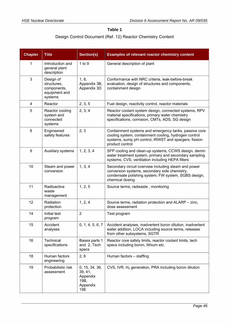
HSE Nuclear Directorate Division 6 Assessment Report No. AR 09/035
Table 1
Design Control Document (Ref. 12) Reactor Chemistry Content
Chapter Title Section(s) Examples of relevant reactor chemistry content
1 Introduction and general plant description
1 to 9 General description of plant
3 Design of structures, components, equipment and systems
1, 8, Appendix 3B, Appendix 3D
Conformance with NRC criteria, leak-before-break evaluation, design of structures and components, containment design
4 Reactor 2, 3, 5 Fuel design, reactivity control, reactor materials
5 Reactor cooling system and connected systems
2, 3, 4 Reactor coolant system design, connected systems, RPV material specifications, primary water chemistry specifications, corrosion, CMTs, ADS, SG design
6 Engineered safety features
2, 3 Containment systems and emergency tanks, passive core cooling system, containment cooling, hydrogen control systems, sump pH control, IRWST and spargers, fission product control
9 Auxiliary systems 1, 2, 3, 4 SFP cooling and clean-up systems, CCWS design, demin water treatment system, primary and secondary sampling systems, CVS, ventilation including HEPA filters
10 Steam and power conversion
1, 3, 4 Secondary circuit overview including steam and power conversion systems, secondary side chemistry, condensate polishing system, FW system, SGBS design, chemical dosing
11 Radioactive waste management
1, 2, 5 Source terms, radwaste , monitoring
12 Radiation protection
1, 2, 4 Source terms, radiation protection and ALARP – zinc, dose assessment
14 Initial test program
2 Test program
15 Accident analyses
0, 1, 4, 5, 6, 7 Accident analyses, inadvertent boron dilution, inadvertent water addition, LOCA including source terms, releases from other subsystems, SGTR
16 Technical specifications
Bases parts 1 and 2, Tech specs
Reactor core safety limits, reactor coolant limits, tech specs including boron, lithium etc.
18 Human factors engineering
2, 6 Human factors – staffing
19 Probabilistic risk assessment
0, 15, 34, 36, 39, 41, Appendix 19B, Appendix 19E
CVS, IVR, H2 generation, PRA including boron dilution
Page 46

HSE Nuclear Directorate Division 6 Assessment Report No. AR 09/035
Table 2
Relevant Safety Assessment Principles Considered During Step 3
SAP Title Description
Engineering principles: Key principles
EKP.2 Fault tolerance The underpinning safety aim for any nuclear facility should be an inherently safe design, consistent with the operational purposes of the facility.
EKP.3 Defence in depth A nuclear facility should be so designed and operated that defence in depth against potentially significant faults or failures are achieved by the provision of several levels of protection.
EKP.4 Safety function The safety function(s) to be delivered within the facility should be identified by a structured analysis.
Engineering principles: Safety classification and standards
ECS.2 Safety classification of structures, systems and components
Structures, systems and components that have to deliver safety functions should be identified and classified on the basis of those functions and their significance with regard to safety.
ECS.3 Standards Structures, systems and components that are important to safety should be designed, manufactured, constructed, installed, commissioned, quality assured, maintained, tested and inspected to the appropriate standards.
ECS.4 Codes and standards
For structures, systems and components that are important to safety, for which there are no appropriate established codes or standards, an approach derived from existing codes or standards for similar equipment, in applications with similar safety significance, may be applied.
ECS.5 Use of experience, tests or analysis
In the absence of applicable or relevant codes and standards, the results of experience, tests, analysis, or a combination thereof, should be applied to demonstrate that the item will perform its safety function(s) to a level commensurate with its classification.
Engineering principles: Ageing and degradation
EAD.1 Safe working life The safe working life of structures, systems and components that are important to safety should be evaluated and defined at the design stage.
EAD.2 Lifetime margins Adequate margins should exist throughout the life of a facility to allow for the effects of materials ageing and degradation processes on structures, systems and components that are important to safety.
EAD.3 Periodic measurement of material properties
Where material properties could change with time and affect safety, provision should be made for periodic measurement of the properties.
EAD.4
Periodic measurement of parameters
Where parameters relevant to the design of plant could change with time and affect safety, provision should be made for their periodic measurement.
Page 47
HSE Nuclear Directorate Division 6 Assessment Report No. AR 09/035
Page 48
SAP Title Description
Engineering principles: Layout
ELO.3 Obsolescence A process for reviewing the obsolescence of structures, systems and components important to safety should be in place.
Engineering principles: External and internal hazards
EHA.13 Fire, explosion, missiles, toxic gases etc – use and storage of hazardous materials
The on-site use, storage or generation of hazardous materials should be minimised, and controlled and located so that any accident to, or release of, the materials will not jeopardise the establishing of safe conditions on the facility.
Engineering principles: Pressure systems
EPS.2 Flow limitation Flow limiting devices should be provided to piping systems that are connected to or form branches from a main pressure circuit, to minimise the consequences of postulated breaches.
EPS.3 Pressure relief Adequate pressure relief systems should be provided for pressurised systems and provision should be made for periodic testing.
EPS.4 Overpressure protection
Overpressure protection should be consistent with any pressure-temperature limits of operation.
EPS.5 Discharge routes Pressure discharge routes should be provided with suitable means to ensure that any release of radioactivity from the facility to the environment is minimised.
Engineering principles: Integrity of metal components and structures
EMC.2 Use of scientific and technical issues
The safety case and its assessment should include a comprehensive examination of relevant scientific and technical issues, taking account of precedent when available.
EMC.16 Contamination The potential for contamination of materials during manufacture and installation should be controlled to ensure the integrity of components and structures is not compromised.
EMC.21 Safe operating envelope
Throughout their operating life, safety-related components and structures should be operated and controlled within defined limits consistent with the safe operating envelope defined in the safety case.
Engineering principles: Safety systems
ESS.1 Requirement for safety systems
All nuclear facilities should be provided with safety systems that reduce the frequency or limit the consequences of fault sequences, and that achieve and maintain a defined safe state.
ESS.2 Determination of safety system requirements
The extent of safety system provisions, their functions, levels of protection necessary to achieve defence in depth and required reliabilities should be determined.
ESS.3
Monitoring of plant safety
Adequate provisions should be made to enable the monitoring of the plant state in relation to safety and to enable the taking of any necessary safety actions.
HSE Nuclear Directorate Division 6 Assessment Report No. AR 09/035
Page 49
SAP Title Description
ESS.4
Adequacy of initiating variables
Variables used to initiate a safety system action should be identified and shown to be sufficient for the purpose of protecting the facility.
ESS.16 No dependency on external sources of energy
Where practicable, following a safety system action, maintaining a safe facility state should not depend on an external source of energy.
Engineering principles: Control and instrumentation of safety-related systems
ESR.8 Monitoring of radioactive substances
Instrumentation should be provided to enable monitoring of the locations and quantities of radioactive substances that may escape from their engineered environment.
Engineering principles: Control of nuclear matter
ENM.1 Strategies for nuclear matter
A strategy (or strategies) should be made and implemented for the management of nuclear matter.
ENM.2 Provisions for nuclear matter brought onto, or generated on, the site
Nuclear matter should not be generated on the site, or brought onto the site, unless sufficient and suitable arrangements are available for its safe management.
ENM.3 Transfers and accumulation of nuclear matter
Unnecessary or unintended generation, transfer or accumulation of nuclear matter should be avoided.
ENM.4 Control and accountancy of nuclear matter
Nuclear matter should be appropriately controlled and accounted for at all times.
ENM.5 Characterisation and segregation
Nuclear matter should be characterised and segregated to facilitate its safe management.
ENM.6 Storage in a condition of passive safety
When nuclear matter is to be stored on site for a significant period of time it should be stored in a condition of passive safety and in accordance with good engineering practice.
ENM.7 Retrieval and inspection of stored nuclear matter
Storage of nuclear matter should be in a form and manner that allows it to be retrieved and, where appropriate, inspected.
ENM.8 Nuclear material accountancy
Nuclear material accountancy data should be analysed and reviewed periodically.
Engineering principles: Containment and ventilation
ECV.1 Prevention of leakage
Radioactive substances should be contained and the generation of radioactive waste through the spread of contamination by leakage should be prevented.
ECV.2
Minimisation of releases
Nuclear containment and associated systems should be designed to minimise radioactive releases to the environment in normal operation, fault and accident conditions.
HSE Nuclear Directorate Division 6 Assessment Report No. AR 09/035
Page 50
SAP Title Description
ECV.3 Means of confinement
The primary means of confining radioactive substance should be by the provision of passive sealed containment systems and intrinsic safety features, in preference to the use of active dynamic systems and components.
ECV.6 Monitoring devices
Suitable monitoring devices with alarms and provisions for sampling should be provided to detect and assess changes in the stored radioactive substances or changes in the radioactivity of the materials within the containment.
ECV.7 Leakage monitoring
Appropriate sampling and monitoring systems and other provisions should be provided outside the containment to detect, locate, quantify and monitor leakages of nuclear matter from the containment boundaries under normal and accident conditions.
ECV.8 Minimisation of provisions
Where provisions are required for the import or export of nuclear matter into or from the facility containments, the number of such provisions should be minimised.
Engineering principles: Reactor core
ERC.1 Design and operation of reactors
The design and operation of the reactor should ensure the fundamental safety functions are delivered with an appropriate degree of confidence for permitted operating modes of the reactor.
ERC.4 Monitoring of safety-related parameters
The core should be designed so that safety-related parameters and conditions can be monitored in all operational and design basis fault conditions and appropriate recovery actions taken in the event of adverse conditions being detected.
Engineering principles: Heat transport systems
EHT.1 Design Heat transport systems should be designed so that heat can be removed or added as required.
EHT.2 Coolant inventory and flow
Sufficient coolant inventory and flow should be provided to maintain cooling within the safety limits for operational states and design basis fault conditions.
EHT.4 Failure of heat transport system
Provisions should be made in the design to prevent failure of the heat transport system that could adversely affect the heat transfer process, or safeguards should be available to maintain the facility in a safe condition and prevent any release in excess of safe limits.
EHT.5 Minimisation of radiological doses
The heat transport system should be designed to minimise radiological doses.
Fault analysis
FA.2 Identification of initiation faults
Fault analysis should identify all initiating faults having the potential to lead to any person receiving a significant dose of radiation, or to a significant quantity of radioactive material escaping from its designated place of residence or confinement.
FA.18 Calculation methods
Calculational methods used for the analyses should adequately represent the physical and chemical processes taking place.
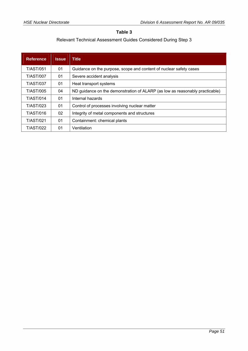
HSE Nuclear Directorate Division 6 Assessment Report No. AR 09/035
Table 3
Relevant Technical Assessment Guides Considered During Step 3
Reference Issue Title
T/AST/051 01 Guidance on the purpose, scope and content of nuclear safety cases
T/AST/007 01 Severe accident analysis
T/AST/037 01 Heat transport systems
T/AST/005 04 ND guidance on the demonstration of ALARP (as low as reasonably practicable)
T/AST/014 01 Internal hazards
T/AST/023 01 Control of processes involving nuclear matter
T/AST/016 02 Integrity of metal components and structures
T/AST/021 01 Containment: chemical plants
T/AST/022 01 Ventilation
Page 51

HSE Nuclear Directorate Division 6 Assessment Report No. AR 09/035
Figure 1
Reactor Chemistry Safety Assessment Principles ‘Mind Map’
Secondary Circuit
Primary Circuit
Auxiliary Facilities
pH Corrosion Cooling
Heat sink
Control Source Term
Boron Emergency Cooling CVS etc.
Process Wastes Radwastes
Materials for Flux Control Fuel Cladding
Feeds
Escapes
Discharges
FA.2, 18 ECS.2 - 5 EMC.2
ECV.1 - 3, 6 - 8
ENM.1 - 8
EPS.2 - 5 EHT.1 - 5
ERC.1, 4 DC.1, 2 EMC.16, 21
ESS.1 - 4, 16 EKP.2, 3, 4 EHA.13
Page 52

HSE Nuclear Directorate Division 6 Assessment Report No. AR 09/035
Annex 1 - Page 1
Annex 1 – Reactor Chemistry – Status of Regulatory Issues and Observations
RI / RO Identifier Date Raised Title Status
Required timescale
(GDA Step 4 / Phase 2)
Regulatory Issues
None
Regulatory Observations
None