Generator - Yamaha Motorsports USA · OWNER’S MANUAL ©2008 by Yamaha Motor Corporation, ......
60
Generator 7CK-28199-10 EF6300iSDE OWNER’S MANUAL PLEASE READ AND UNDERSTAND THIS MANUAL COMPLETELY BEFORE OPERATING THE MACHINE. LIT-19626-01-52
Transcript of Generator - Yamaha Motorsports USA · OWNER’S MANUAL ©2008 by Yamaha Motor Corporation, ......

Generator
7CK-28199-10
EF6300iSDE
OWNER’S MANUAL
PLEASE READ AND UNDERSTAND THIS MANUALCOMPLETELY BEFORE OPERATING THE MACHINE.
LIT-19626-01-52PRINTED ON RECYCLED PAPER
PRINTED IN JAPAN2008 909 – 1.0 × 1 !
7CK-28199-10_hyoshi 08.8.30 14:27 Page 1

7CK-28199-10_hyoshi 08.8.30 14:27 Page 2

AE00002
INTRODUCTIONCongratulations on your purchase of your new Yamaha.This manual will provide you with a good basic understanding of the operation andmaintenance of this machine.If you have any questions regarding the operation or maintenance of your machine,please consult a Yamaha dealer.
EF6300iSDEOWNER’S MANUAL
© 2008 by Yamaha Motor Corporation, U.S.A.1st Edition, September 2008
All rights reserved. Any reprinting or unauthorized use without the written permission of
Yamaha Motor Corporation, U.S.A. is expressly prohibited.
Printed in JapanP/N LIT-19626-01-52
AE00022
7CK-28199-10_a 08.9.15 17:47 Page A-1

Particularly important information is distin-guished in this manual by the followingnotations.
-The Safety Alert Symbol means ATTEN-TION! BECOME ALERT! YOUR SAFETYIS INVOLVED!
wFailure to follow WARNING instructionscould result in severe injury or death tothe engine operator, a bystander or a per-son inspecting or repairing the engine.
cCA CAUTION indicates special precautionsthat must be taken to avoid damage to theengine.
NOTE:A NOTE provides key information to makeprocedures easier or clearer.
AE00032
wPLEASE READ AND UNDERSTANDTHIS MANUAL COMPLETELY BEFOREOPERATING THE MACHINE.
NOTE:9 Yamaha continually seeks advance-
ments in product design and quality.Therefore, while this manual containsthe most current product informationavailable at the time of printing, theremay be minor discrepancies betweenyour engine and this manual. If thereis any question concerning this manu-al, please consult a Yamaha dealer.
9 This manual should be considered apermanent part of this engine andshould remain with this engine whenresold.
* Product and specifications are subject tochange without notice.
IMPOTANT MANUAL INFORMATION
7CK-28199-10_a 08.9.15 17:47 Page A-2

AE00041
CONTENTS
SAFETY INFORMATION ........................1EXHAUST FUMES ARE POISONOUS........................................1FUEL IS HIGHLY FLAMMABLE ANDPOISONOUS........................................1ENGINE AND MUFFLER MAY BE HOT......................................................1ELECTRIC SHOCK PREVENTION......2CONNECTION NOTES........................3CONNECTION .....................................3EXTENSION CORD NOTES................3
LOCATION OF IMPORTANT LABELS...................................................4DESCRIPTION ........................................6
Control Panel........................................6CONTROL FUNCTION............................7
Engine switch .......................................7Oil warning light (red) ...........................7AC protector .........................................8Economy control switch........................8G.F.C.I. receptacle ...............................9Voltage select switch ............................9Hour meter..........................................10Power meter .......................................10AC pilot light (green)...........................10Overload indicator light (red) ..............11Fuel tank cap ......................................11Fuel cock knob ...................................12Ground (Earth) terminal......................12Caster lock lever.................................12
PREPARATION.....................................13Fuel.....................................................13Engine oil............................................14Battery preparation .............................15
PRE-OPERATION CHECK ...................17Pre-operation check ...........................17
OPERATION..........................................18
Starting the engine .............................18Stopping the engine............................20Connection .........................................21Application range................................23
PERIODIC MAINTENANCE ..................25Maintenance chart ..............................25Spark plug inspection .........................27Carburetor adjustment........................28Engine oil replacement .......................28Air filter ...............................................29Muffler screen and spark arrester.......31Fuel tank filter .....................................33Battery ................................................34Recommended battery .......................34Fuse replacement...............................35G.F.C.I. receptacle test.......................36
STORAGE .............................................37Drain the fuel ......................................37Engine ................................................39Battery ................................................40
TROUBLESHOOTING ..........................42Engine won’t start ...............................42Generator won’t produce power .........43
SPECIFICATIONS.................................45Dimensions.........................................45Engine ................................................45Generator ...........................................45Battery ................................................45
CONSUMER INFORMATION................46Identification number records .............46Machine identification .........................46
LIMITED WARRANTY (EF- AND EDL-SERIES) ........................................47
EXHAUST EMISSION CONTROL SYSTEM AND COMPONENTS .........49
WIRING DIAGRAM ...............................51
7CK-28199-10_a 08.9.15 17:47 Page A-3

– 1 –
741-7XFa
741-7XFb
741-7XFc
741-7XFd
741-7XFe
741-7XFf
AE00071
SAFETY INFORMATION
AE00072
EXHAUST FUMES ARE POISONOUS9 Never operate the engine in a closed area or it
may cause unconsciousness and death within ashort time. Operate the engine in a well ventilatedarea.
AE00075
FUEL IS HIGHLY FLAMMABLE AND POISONOUS9 Always turn off the engine when refuelling.9 Never refuel while smoking or in the vicinity of an
open flame.9 Take care not to spill any fuel on the engine or
muffler when refueling.9 If you swallow any fuel, inhale fuel vapor, or allow
any to get in your eye(s), see your doctor immedi-ately. If any fuel spills on your skin or clothing,immediately wash with soap and water andchange your clothes.
9 When operating or transporting the machine, besure it is kept upright. If it tilts, fuel may leak fromthe carburetor or fuel tank.
AE00843
ENGINE AND MUFFLER MAY BE HOT9 Place the machine in a place where pedestrians
or children are not likely to touch the machine.
9 Avoid placing any flammable materials near theexhaust outlet during operation.
7CK-28199-10_a 08.9.15 17:47 Page 1

– 2 –
741-7XFg
a
741-7XFh
1
1 1
794-7CK
741-7XFi
741-7XFj
9 Keep the machine at least 1 m (3 ft) from buildingsor other equipment, or the engine may overheat.
a 1 m (3 ft)
9 Avoid operating the engine with a dust cover.
9 Be sure to carry the generator only by its carryinghandles 1.
AE00083
ELECTRIC SHOCK PREVENTION9 Never operate the engine in rain or snow.
9 Never touch the machine with wet hands or elec-trical shock will occur.
7CK-28199-10_a 08.9.15 17:47 Page 2

– 3 –
1
2
1
2
741-7XFk
AE00088
CONNECTION NOTES9 Avoid connecting the generator to commercial
power outlet.9 Avoid connecting the generator in parallel with any
other generator.
1 Correct2 Incorrect
AE00091
CONNECTIONwBefore the generator can be connected to a build-ing’s electrical system, a licensed electrician mustinstall an isolation (transfer) switch in the build-ing’s main fuse box. The switch is the connectionpoint for generator power and allows selection ofgenerator or main line power to the building. Thiswill prevent the generator from charging the mainpower line (backfeeding) when the main powersupply has failed or has been turned off for linerepair. Backfeeding can electrocute or injure linemaintenance personnel. Also, generator and build-ing electrical system damage can occur when nor-mal operating power returns if unit is used withoutan isolation switch.
AE00086
EXTENSION CORD NOTESExtension cords should be protected by a tough flexi-ble rubber sheath (IEC 245) or the equivalent to with-stand mechanical stresses.
9 Connect the ground lead of the machine to theground (earth) terminal 1 and connect the end tothe ground electrode buried in the ground.
1763-7CKa
7CK-28199-10_a 08.9.15 17:47 Page 3
– 4 –
AE00062
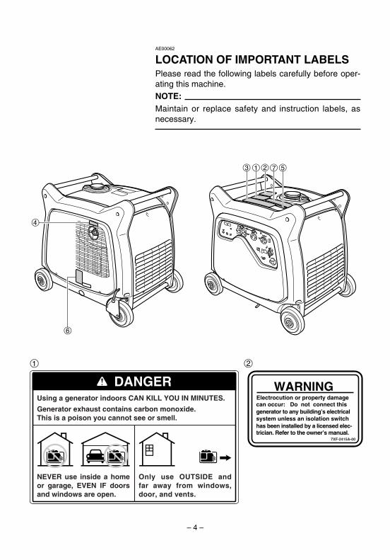
LOCATION OF IMPORTANT LABELSPlease read the following labels carefully before oper-ating this machine.NOTE:Maintain or replace safety and instruction labels, asnecessary.
1
DANGERUsing a generator indoors CAN KILL YOU IN MINUTES.
Generator exhaust contains carbon monoxide.This is a poison you cannot see or smell.
NEVER use inside a home or garage, EVEN IF doors and windows are open.
Only use OUTSIDE and far away from windows, door, and vents.
4
6
1 753 2
2
WARNINGElectrocution or property damagecan occur: Do not connect thisgenerator to any building’s electricalsystem unless an isolation switchhas been installed by a licensed elec-trician. Refer to the owner’s manual.
7XF-2415A-00
7CK-28199-10_a 08.9.15 17:47 Page 4

– 5 –
4 6
3
7
WARNINGREAD THE OWNER‘S MANUAL AND ALL LABELS BEFORE OPERATING.
q qAVERTISSEMENT8
ONLY OPERATE IN WELL-VENTILATED AREAS.EXHAUST GAS CONTAINS POISONOUS CARBON MONOXIDE.CHECK FOR SPILLED FUEL OR FUEL LEAKS.STOP ENGINE BEFORE REFUELING.DO NOT OPERATE NEAR FLAMMABLE MATERIALS.ELECTROCUTION CAN OCCUR IF GENERATOR IS USED IN RAIN,SNOW, OR NEAR WATER. KEEP THIS UNIT DRY AT ALL TIMES.
8
8
8
8
8
MACHINE AUSEC EN TOUTES CIRCONSTANCES.
8
8
8
8
8
8
LISEZ LE MODE D‘EMPLOI ET TOUTES LES ETIQUETTES AVANT DEFAIRE FONCTIONNER LA MACHINE.FAITES FONCTIONNER UNIQUEMENT DANS DES LIEUX BIEN AERES.LES GAZ D‘ECHAPPEMENT CONTIENNENT 0U MONOXYDE DE CARBONE.VERIFIEZ SI DU CARBURANT A ETE RENVERSE DU S‘IL FUIT.ARRETEZ LE MOTEUR AVANT DE FAIRE LE PLEIN DE CARBURANT.N‘UTILISEZ PAS A PROXIMITE DE MATERIAUX INFLAMMABLES.IL Y A RISQUE D‘ELECTROCUTION SI LE GENERATEUR FONCTIONNESOUS LA PLUIE, DANS LA NEIGE, OU PRES DE L‘EAU. GARDEZ LA
7CF-24162-10
Important Emissions Information The air index of this engine is 3(California only)
MOST CLEAN LEAST CLEAN0 2 4 6 8 10
YAMAHA MOTOR POWERED PRODUCTS CO.,LTD.This engine meets **** California exhaust and evaporativeemission regulations for small off-road engines.This engine conforms to Phase 2 U.S.EPA regulations forsmall nonroad engines.EMISSIONS COMPLIANCE PERIOD : CATEGORY A(EPA)EF: *YMXS.3572EA DISPLACEMENT: 357ccEVAP F: CMYMX23A EMISSION CONTROL SYSTEM: EMThis engine is certified to operate on unleaded gasoline.ENGINE OIL: SAE10W-30 TYPE: SENo other adjustments needed.
Note: The lower the air index, the less the pollution.This engine is certified to be emissions compliantfor the following use:
Check owner's manual for further details.
MODERATE(250 HOURS)
INTERMEDIATE(500 HOURS)
EXTENDED(1000 HOURS)X
HOT EXHAUST7WL-28176-10
5
q CAUTIONUse the specified spark plug only.
Specified plug:BPR4ES(NGK)
OIL
zzzzzz
AC output zzHz
Rated zzzzVA
Phase SingleFuel Gasoline
YAMAHA MOTOR POWERED PRODUCTS CO.,LTD.MADE IN JAPAN
zzzV
7CK-24164-10
7CK-28199-10_a 08.9.15 17:47 Page 5

– 6 –
DESCRIPTION
AE00102
1 Carrying handles (shaded)2 Fuel tank cap3 Fuel gauge4 Muffler5 Caster lock lever 6 Oil filler cap7 Oil drain bolt8 Battery
AE00103
Control panel1 Hour meter2 Power meter3 G.F.C.I. receptacle4 AC protector5 AC receptacle6 Engine switch7 Fuel cock knob8 Voltage select switch9 Ground (Earth) terminal0 Economy control switchq Overload indicator lightw AC pilot lighte Oil warning light
8
7
6
1 3 4
90w qe
2 5
793-7CK
3 121
1
793-7CKa
7 6 58
4
1
793-7CKb
7CK-28199-10_a 08.9.15 17:47 Page 6

763-119
q
w e
– 7 –
700-7XF
AE00111
Oil warning light (red)When the oil level falls below the lower level, the oilwarning light comes on and then the engine stopsautomatically. Unless you refill with oil, the engine willnot start again.
NOTE:If the engine stalls or does not start, turn the engineswitch to “START”. If the oil warning light comes on,the engine oil is insufficient. Add oil and restart.
AE00101
CONTROL FUNCTIONAE00121
Engine switchThe engine switch controls the ignition system.
1 7 “ON”
Ignition circuit is switched on.The engine can be started.
2 5 “STOP”
Ignition circuit is switched off.The engine will not run.
3 6 “START”
Starting circuit is switched on.The starter motor starts and the engine can be started.Take your hand off the switch immediately after theengine starts.
7CK-28199-10_a 08.9.15 17:47 Page 7

– 8 –
1
42
3
793-7CKe
AE00134
AC protectorThe AC protector 1 trips when total amount of thereceptacles 2 loads exceed 20A.The AC protector 3 trips when the receptacle 4 loadsexceed 30A.
Press the switches to reset the AC protectors.
1 I “Set”2 3 “Reset”
763-238a
1
2
AE00142
Economy control switch
1 I “ON”
When the economy control switch is turned to “ON”,the economy control unit controls the engine speedaccording to the connected load. The results are betterfuel consumption and less noise.
2 3 “OFF”
When the economy control switch is turned to “OFF”,the engine runs at the rated r/min (3,400 r/min) regard-less of whether is a load connected or not.
NOTE:The economy control switch must be turned to “OFF”when using electric devices that require a large start-ing current, such as a compressor of a submergiblepump.
ON OFF
1 2ECON.SW
763-124a
7CK-28199-10_a 08.9.15 17:47 Page 8

– 9 –
TE
ST
RE
SE
T
RE
SE
T
TE
ST
w
q
763-083c
e
763-060
AE00848
G.F.C.I. receptaclewTO REDUCE THE CHANCE OF ELECTRICALSHOCK:9 Do not attempt to operate electric devices if
the ground fault circuit interrupter reset buttonpops out repeatedly during use.
9 Test the ground fault circuit interrupter duringthe pre-operation checks according to themaintenance instructions on page 36.
9 Remember that only receptacle labeled “GFCI”have ground fault circuit interrupter protec-tion.
The G.F.C.I. (Ground Fault Circuit Interrupter) 1 shutsoff power to the protected receptacles if a ground fault(electrical leak) is detected.If the reset button 2 pops out 3, the electric devicesconnected into the receptacle may be faulty. If thishappens, check the electric devices carefully. If theelectric devices appears to be in good condition, pressthe reset button firmly until a click is heard. This willrestore power. If the reset button pops out again, dis-connect all the electric devices immediately. Have theelectric devices inspected and repaired by a qualifiedrepairperson before attempting to use them again.
Voltage select switchcCDo not operate the voltage select switch while theengine is running.
1 “120/240V”
When the voltage select switch is turned to “120/240V”1, the generator supplies both 120V and 240V.
2 “120V”
When the voltage select switch is turned to “120V” 2,the generator supplies 120V only.799-7CK
1 2NO SWITCHINGDURING OPERATION.
WHEN SWITCHING TO 120V.THE 120/240V OUTLETCANNOT BE USED.
120/240V 120V
7CK-28199-10_a 08.9.15 17:47 Page 9

– 10 –
1
763-7CKf
1
763-7CKg
1
763-7CKc
Hour meterThe hour meter 1 shows the total number of hoursthe generator has been run.
Power meterThe power meter 1 shows the amount of electric cur-rent used by a barmeter.The generator output is normal when the segments ofthe barmeter appear.NOTE:When 10 segments appear, the generator has almostreached its rated output.
AC pilot light (green)The AC pilot light 1 comes on when the engine startsand produces power.
NOTE:If you operate the generator with the voltage selectswitch in the 120/240V-position, the electric currentwill be limited for the 120V-receptacles.When you use either receptacle 1 or 2 AND recepta-cle 3 at the same time, the total electric current pro-vided will be equal to or even less than 22.9A.For example: If the 240V-receptacle provides 10A, the 120V-recep-tacles 1 and 2 can be used up to 12.9A each.In case the load exceeds 22.9A, the overload indicatorlight will turn on and the generator will stop. (At thismoment the segments of the powermeter may notreach 10)If you operate the generator with the voltage selectswitch in the 120V-position, the receptacles 1 and 2can supply rated current (45.8A).
213
793-7CKf
7CK-28199-10_a 08.9.15 17:47 Page 10

– 11 –
AE01087
Overload indicator light (red)The overload indicator light 1 comes on when anoverload of a connected electrical device is detected,the inverter control unit overheats, or the AC outputvoltage rises. Then, the AC protector will trip, stoppingpower generation in order to protect the generator andany connected electric devices. The AC pilot light(green) will go off and the overload indicator light (red)will stay on, but the engine will not stop running.
When the overload indicator light comes on and powergeneration stops, proceed as follows:1. Turn off any connected electric devices and stop
the engine.2. Reduce the total wattage of connected electric
devices within the rated output.3. Check for blockages in the cooling air inlet and
around the control unit. If any blockages arefound, remove.
4. After checking, restart the engine.
NOTE:The overload indicator light may come on for a fewseconds at first when using electric devices thatrequire a large starting current, such as a compressoror a submergible pump. However, this is not a mal-function.
1
763-7CKd
707-7XFb
Fuel tank capRemove the fuel tank cap by turning it counterclock-wise.
7CK-28199-10_a 08.9.15 17:47 Page 11

– 12 –
763-7CKb
ON
OFF
1
2
705-073d
1763-7CKa
Fuel cock knobThe fuel cock supplies fuel from the fuel tank to thecarburetor.The fuel cock has two positions.
1 “ON”
With the knob in this position, fuel flows to the carbure-tor. Normal using is done with the knob in this position.
2 “OFF”
With the knob in this position, fuel will not flow. Alwaysturn the knob to this position when the engine is notrunning.
Ground (Earth) terminalGround (Earth) terminal 1 connects the earth line forprevention of electric shock.When the electric device is earthed, always the gener-ator must be earthed.
1
2
788-7CKh
Caster lock leverThe caster lock lever stops moving the generator.
1 “Release”2 “Lock”
7CK-28199-10_a 08.9.15 17:47 Page 12

– 13 –
741-7XFl
1
2
707-7XF
707-7XFc
3 4
707-7XFa
PREPARATIONAE00856
Fuelw9 Fuel is highly flammable and poisonous.
Check “SAFETY INFORMATION” (See page 1)carefully before filling.
9 Do not overfill the fuel tank, otherwise it mayoverflow when the fuel warms up andexpands.
9 After fill the fuel, make sure the fuel tank cap istightened securely.
cC9 Immediately wipe off spilled fuel with a clean,
dry, soft cloth, since fuel may deterioratepainted surfaces or plastic parts.
9 Use only unleaded gasoline. The use of leadedgasoline will cause severe damage to internalengine parts.
Make sure there is sufficient fuel in the tank.When refueling, be sure to fill the tank to the bottomedge of the fuel filter 4.1 Fuel level gauge2 Red line
3 Fuel level
Your Yamaha engine has been designed to use regu-lar unleaded gasoline with a pump octane number ((R+ M)/2) of 86 or higher, or research octane number of91 or higher.
Recommended fuel: Unleaded gasoline
Fuel tank capacity:Total:
17.0 L (3.17 US gal, 2.64 Imp gal)
“F” FullRed line 2 Empty
7CK-28199-10_a 08.9.15 17:47 Page 13

– 14 –– 14 –
3700-7XFa
700-103c
r
0°C
å YAMALUBE 4 (10W-40)
∂ SAE 10W ç SAE #20 ∫ SAE #30
32°F
25°C
80°F
700-006
AE00222
Engine oilcCThe generator has been shipped without engineoil. Do not start the engine till fill with the suffi-cient engine oil.
1. Place the generator on a level surface.2. Remove the bolts 1, and then pull outward on the
areas of rear cover 2 shown.
3. Remove the oil filler cap 3.4. Fill the specified amount of the recommended
engine oil, and then install and tighten the oil fillercap.
4 Upper level
1
2
788-7CKb
5. Install the rear cover and tighten the bolts.
Recommended engine oil:åYAMALUBE 4 (10W-40),
SAE 10W-30 or 10W-40∫SAE #30çSAE #20∂SAE 10W
Recommended engine oil grade:API Service SE type or higher
Engine oil quantity:1.3 L (1.37 US qt, 1.14 lmp qt)
7CK-28199-10_a 08.9.15 17:47 Page 14

– 15 –
AE01083
Battery preparation(See page 34)
w9 Electrolyte is poisonous and dangerous since
it contains sulfuric acid, which causes severeburns. Avoid any contact with skin, eyes orclothing and always shield your eyes whenworking near batteries. In case of contact,administer the following FIRST AID.9 EXTERNAL: Flush with plenty of water.9 INTERNAL: Drink large quantities of water or
milk and immediately call a physician.9 EYES: Flush with water for 15 minutes and
seek prompt medical attention.9 Batteries produce explosive hydrogen gas.
Therefore, keep sparks, flames, cigarettes,etc., away from the battery and provide suffi-cient ventilation when charging it in anenclosed space.
9 KEEP THIS AND ALL BATTERIES OUT OF THEREACH OF CHILDREN.
762-012
1. Remove the bolts 1, and then pull outward on theareas of rear cover 2 shown.
2. Remove the wing nuts 3 and battery plate 4.3. Remove the battery 5.4. Fill the battery with the electrolyte.
Refer to the instruction sheet included with theelectrolyte for filling instructions.
1
2
788-7CKb
3
5
4
762-7XFa
67
762-7XFc
5. Connect the positive lead (red) 6 to the positive(+) battery terminal 7.
6. Install the battery onto the tray.7. Install the battery plate and tighten the wing nuts.
7CK-28199-10_a 08.9.15 17:47 Page 15

– 16 –
8. Connect the negative lead (black) 8 to the nega-tive (-) battery terminal 9.
9. Install the rear cover and tighten the bolts.
9
762-7CKd
8
7CK-28199-10_a 08.9.15 17:47 Page 16

– 17 –
AE00845
PRE-OPERATION CHECKwIf any item in the Pre-operation check is not work-ing properly, have it inspected and repaired beforeoperating the generator.
The condition of a generator is the owner's responsibil-ity. Vital components can start to deteriorate quicklyand unexpectedly, even if the generator unused.
NOTE:Pre-operation checks should be made each time thegenerator is used.
Pre-operation checkFuel (See page 13)9 Check fuel level in fuel tank.9 Refuel if necessary.
Fuel line9 Check fuel hose for crack or damage.9 Replace if necessary.
Engine oil (See page 14)9 Check oil level in engine.9 If necessary, add recommended oil to specified
level.9 Check generator for oil leakage.
The point where abnormality was recognized byuse9 Check operation.9 If necessary, consult a Yamaha dealer.
7CK-28199-10_a 08.9.15 17:47 Page 17
– 18 –
761-7CKb
705-073
ON
OFF
q
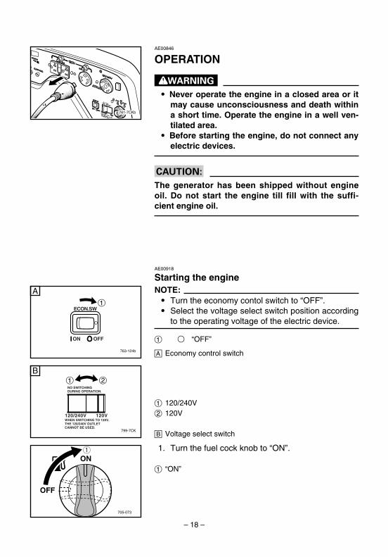
AE00846
OPERATION
w9 Never operate the engine in a closed area or it
may cause unconsciousness and death withina short time. Operate the engine in a well ven-tilated area.
9 Before starting the engine, do not connect anyelectric devices.
cCThe generator has been shipped without engineoil. Do not start the engine till fill with the suffi-cient engine oil.
AE00918
Starting the engineNOTE:9 Turn the economy contol switch to “OFF”.9 Select the voltage select switch position according
to the operating voltage of the electric device.
1 3 “OFF”
å Economy control switch763-124b
ON OFF
1ECON.SW
A
799-7CK
1 2NO SWITCHINGDURING OPERATION.
WHEN SWITCHING TO 120V.THE 120/240V OUTLETCANNOT BE USED.
120/240V 120V
B
1. Turn the fuel cock knob to “ON”.
1 “ON”
1 120/240V2 120V
∫ Voltage select switch
7CK-28199-10_a 08.9.15 17:47 Page 18

– 19 –
763-120a
q
3. Turn the engine switch to “START”.Take your hand off the switch immediately afterthe engine starts.
1 6 “START”
cCIf the engine fails to start, release the switch, waita few seconds, then try again. Each attemptshould be as short as possible to preserve the bat-tery. Do not crank the engine more than 5 secondson any one attempt.
2. Turn the engine switch to “ON”.
1 7 “ON”
763-127h
1
7CK-28199-10_a 08.9.15 17:47 Page 19

– 20 –
761-7CKb
763-120b
q
705-073a
ON
OFFq
4. Turn the fuel cock knob to “OFF”.
1 “OFF”
AE00840
Stopping the engine
1. Turn off any electric devices.
2. Disconnect any electric devices.
3. Turn the engine switch to “STOP”.
1 5 “STOP”
7CK-28199-10_a 08.9.15 17:47 Page 20

– 21 –
AE00839
ConnectionAlternating Current (AC)
wBe sure any electric devices are turned off beforeplugging them in.
cC9 Be sure all electric devices including the lines
and plug connections are in good conditionbefore connection to the generator.
9 Be sure the total load is within generator ratedoutput.
9 Be sure the receptacle load current is withinreceptacle rated current.
9 Do not operate the voltage select switch whilethe engine is running.
NOTE:Make sure to ground (earth) the generator.When the electric device is earthed, always the gener-ator must be earthed.
1. Select the voltage select switch position accordingto the operating voltage of the electric device.
1 120/240V2 120V
2. Start the engine.
761-7CKa
3. Plug in to AC receptacle.
NOTE:To supply both 120V and 240V power sources fromthe 4-blade plug receptacle needs special knowledgeof the wiring plug. Please contact a trained electricianfor the wiring of the plugs.
799-7CK
1 2NO SWITCHINGDURING OPERATION.
WHEN SWITCHING TO 120V.THE 120/240V OUTLETCANNOT BE USED.
120/240V 120V
779-017a
YW
XG
GR
120V
120V240V
7CK-28199-10_a 08.9.15 17:47 Page 21

– 22 –
763-124c
ON OFF
1ECON.SW
A
4. Make sure the AC pilot light 1 is on.
5. Turn the economy control switch to “ON”
1 I “ON”
å Economy control switch
6. Turn on any electric devises.NOTE:The economy control switch must be turned to “OFF”to increase engine speed to rated rpm.
1
763-7CKc
7CK-28199-10_a 08.9.15 17:47 Page 22

– 23 –
AE00812
Application rangeWhen using the generator, make sure the total load is within rated output of a generator.Otherwise, generator damage may occur.
AC
Power factor 1 0.8 ~ 0.950.4 ~ 0.75
(Efficiency 0.85)
EF6300iSDE – 5,500W – 4,400W – 1,870W
NOTE:9 “–” means below.9 Application wattage indicates when each device is
used by itself.9 The overload indicator light 1 comes on when
total wattage exceeds the application range. (Seepage 11 for more details.)
cC9 Do not overload. The total load of all electrical
appliances must not exceed the supply rangeof the generator. Overloading will damage thegenerator.
9 When supplying precision equipment, elec-tronic controllers, PCs, electronic computers,microcomputerbased equipment or batterychargers, keep the generator a sufficient dis-tance away to prevent electrical interferencefrom the engine. Also ensure that electricalnoise from the engine does not interfere withany other electrical devices located near thegenerator.
9 If the generator is to supply medical equip-ment, advice should first be obtained from themanufacturer, a medical professional or hospi-tal.
9 Some electrical appliances or general-purposeelectric motors have high starting currents,and cannot therefore be used, even if they liewithin the supply ranges given in the abovetable. Consult the equipment manufacturer forfurther advice.
1
763-7CKd
7CK-28199-10_a 08.9.15 17:47 Page 23

– 24 –
— MEMO —
7CK-28199-10_a 08.9.15 17:47 Page 24

– 25 –
AE00401
PERIODIC MAINTENANCESafety is an obligation of the owner. Periodic inspection, adjustment and lubrication willkeep your generator in the safest and most efficient condition possible. The most impor-tant points of generator inspection, adjustment, and lubrication are explained on the fol-lowing pages.
wIf you are not familiar with maintenance work, have a Yamaha dealer do it for you.
AE00403
Maintenance chartwStop the engine before starting maintenance work.
cCUse only Yamaha specified genuine parts for replacement. Ask an authorizedYamaha dealer for further attention.
Item RoutinePre-
operationcheck
Every
6 months or 100 Hr
12 monthsor 300 Hr
Spark plug• Check condition.
1
• Clean and replace if necessary.
Fuel • Check fuel level and leakage. 1
Fuel hose • Check fuel hose for cracks or damage.1
Replace if necessary.
Engine oil• Check oil level in engine. 1
• Replace 1(*1)
Air filter element• Check condition.
1(*2)• Clean
Muffler screen• Check condition.
1
• Clean and replace if necessary.
Spark arrester• Check condition.
1
• Clean and replace if necessary.
Fuel filter • Clean and replace if necessary. 1
7CK-28199-10_a 08.10.2 16:29 Page 25

– 26 –
*1····· Initial replacement of the engine oil is after one month or 20 hours of operation.*2·····The air filter element needs to be cleaned more frequently when using in unusually wet or dusty areas.★····· Since these items require special tools, data and technical skills, have a Yamaha dealer perform the ser-
vice.
Item RoutinePre-
operationcheck
Every
6 months or 100 Hr
12 monthsor 300 Hr
Crankcase breather • Check breather hose for cracks or
hosedamage. 1
• Replace if necessary.
Cylinder head• Decarbonize cylinder head.
★• More frequently if necessary.
Valve clearance • Check and adjust when engine is cold. ★
Fittings / fasteners• Check all fittings and fasteners.
★• Correct if necessary.
The point where abnormality was recognized by use 1
7CK-28199-10_a 08.9.15 17:47 Page 26

4. Check the spark plug type and gap a.
NOTE:The spark plug gap should be measured with a wirethickness gauge and, if necessary, adjusted to specifi-cation.
5. Install the spark plug.
NOTE:If a torque wrench is not available when installing aspark plug, a good estimate of the correct torque is1/4-1/2 turn past finger tight. However, the spark plugshould be tightened to the specified torque as soon aspossible.
6. Install the spark plug cap.7. Install the front cover and tighten the bolts.
2. Remove the spark plug cap and then remove thespark plug.
3. Check for discoloration and remove the carbon.The porcelain insulator around the center elec-trode of spark plug should be a medium-to-lighttan color.
– 27 –
760-7XF
a
760-001a
AE01051
Spark plug inspectionThe spark plug is important engine components, whichshould be checked periodically.1. Remove the bolts 1, and then pull outward on the
areas of front cover 2 shown.
Standard Spark Plug:BPR4ES (NGK)
Spark Plug Gap:0.7–0.8 mm (0.028–0.031 in)
Spark Plug Torque:20.0 N•m (2.0 kgf•m, 14.8 lbf•ft)
1
2
788-7CKa
7CK-28199-10_b 08.9.15 17:13 Page 27

3. Remove the rubber cap 3, rubber plug 4 and theoil filler cap 5.
4. Place an oil pan under the engine. Remove the oildrain bolt 6 so that the oil can be completelydrained.
5. Check the oil drain bolt, gasket 7, oil filler capand O-ring 8.If damaged, replace.
6. Reinstall the oil drain bolt.
1. Place the machine on a level surface and warmup the engine for several minutes.Then stop the engine.
2. Remove the bolts 1, and then pull outward on theareas of rear cover 2 shown.
– 28 –
3
5
67
8
4 700-7XFb
1
2
788-7CKb
AE00412
Engine oil replacementwAvoid draining the engine oil immediately afterstopping the engine. The oil is hot and should behandled with care to avoid burns.
Oil drain bolt Torque:30.0 N•m (3.1 kgf•m, 22.2 lbf•ft)
AE00431
Carburetor adjustmentThe carburetor is a vital part of the engine. Adjustingshould be left to a Yamaha dealer with the profession-al knowledge, specialized data, and equipment to doso properly.
7CK-28199-10_b 08.9.15 17:13 Page 28

– 29 –
cCBe sure no foreign material enters the crankcase.
8. Install the oil filler cap, the rubber cap and the rub-ber plug.
9. Install the front cover and tighten the bolts.
AE01084
Air filter1. Remove the bolts 1, and then pull outward on the
areas of front cover 2 shown.
2. Remove the bolts 3.
1
2
788-7CKa
3
3
788-7XFi
7. Add engine oil to the upper level 1.
700-006a
q Recommended engine oil:åYAMALUBE 4 (10W-40),
SAE 10W-30 or 10W-40∫SAE #30çSAE #20∂SAE 10W
Recommended engine oil grade:API Service SE type or higher
Engine oil quantity:1.3 L (1.37 US qt, 1.14 lmp qt)
0°C
å YAMALUBE 4 (10W-40)
∂ SAE 10W ç SAE #20 ∫ SAE #30
32°F
25°C
80°F
7CK-28199-10_b 08.9.15 17:13 Page 29

– 30 –
3. Remove the air filter cover 1 and foam element2.
4. Wash the foam element in solvent and dry it.5. Oil the foam element and squeeze out excess oil.
The foam element should be wet but not dripping.
cCDo not wring out the foam element when squeez-ing it.This could cause it to tear.
6. Insert the foam element into the air filter case.
NOTE:Be sure the foam element sealing surface matches theair filter so there is no air leak.
cCThe engine should never run without the foam ele-ment; excessive piston and cylinder wear mayresult.
7. Install the air filter cover in its original position andtighten the bolts.
8. Install the front cover and tighten the bolts.
Recommended oil:Foam-air-filter oil
orSAE #20 motor oil
710-037a
1 2
7CK-28199-10_b 08.9.15 17:13 Page 30

– 31 –
741-7XFl
1
2
788-7CKb
1
2
3
711-7XFa
711-7XFb
4 711-7XFc
AE01075
Muffler screen and spark arrester
wThe engine and muffler will be very hot after theengine has been run.Avoid touching the engine and muffler while theyare still hot with any part of your body or clothingduring inspection or repair.
2. Loosen the screw 1 and then remove the mufflercap 2, the muffler screen 3 and spark arrester4.
1. Remove the bolts 1, and then pull outward on theareas of rear cover 2 shown.
7CK-28199-10_b 08.9.15 17:13 Page 31

– 32 –
2
1
711-7XFd
711-7XFe
6. Install the muffler screen and the muffler cap.7. Install the rear cover and tighten the bolts.
3. Remove the carbon deposits on the mufflerscreen and spark arrester using a wire brush.
cCWhen cleaning, use the wire brush lightly to avoiddamaging or scratching of the muffler screen andspark arrester.
4. Check the muffler screen and spark arrester.Replace them if damaged.
5. Install the spark arrester.
NOTE:Align the spark arrester projection 1 with the hole 2in the muffler pipe.
711-075
7CK-28199-10_b 08.9.15 17:13 Page 32

– 33 –
707-043b
q
AE00471
Fuel tank filterwNever use or be near the fuel and solvent whilesmoking or in the vicinity of an open flame.
1. Remove the fuel tank cap and filter 1.2. Clean the filter with gasoline.
If damaged, replace it.3. Wipe the filter and install it.4. Install the fuel tank cap.
wBe sure the fuel tank cap is tightened securely.
7CK-28199-10_b 08.9.15 17:13 Page 33

– 34 –
762-012
AE00842
BatteryThis generator is equipped with a sealed type (MF)battery, which does not require any maintenance.There is no need to check the electrolyte or to add dis-tilled water.
w9 Electrolyte is poisonous and dangerous since
it contains sulfuric acid, which causes severeburns. Avoid any contact with skin, eyes orclothing and always shield your eyes whenworking near batteries. In case of contact,administer the following FIRST AID.9 EXTERNAL: Flush with plenty of water.9 INTERNAL: Drink large quantities of water or
milk and immediately call a physician.9 EYES: Flush with water for 15 minutes and
seek prompt medical attention.9 Batteries produce explosive hydrogen gas.
Therefore, keep sparks, flames, cigarettes,etc., away from the battery and provide suffi-cient ventilation when charging it in anenclosed space.
9 KEEP THIS AND ALL BATTERIES OUT OF THEREACH OF CHILDREN.
To charge the batteryHave a Yamaha dealer charge the battery as soon aspossible if it seems to have discharged.
AE01057
Recommended battery
Recommended battery:Capacity: 12V/18Ah
7CK-28199-10_b 08.9.15 17:13 Page 34
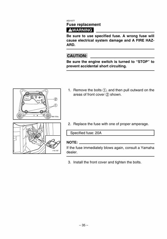
2. Replace the fuse with one of proper amperage.
NOTE:If the fuse immediately blows again, consult a Yamahadealer.
3. Install the front cover and tighten the bolts.
– 35 –
1
2
788-7CKa
779-7XF
AE01077
Fuse replacementwBe sure to use specified fuse. A wrong fuse willcause electrical system damage and A FIRE HAZ-ARD.
cCBe sure the engine switch is turned to “STOP” toprevent accidental short circuiting.
Specified fuse: 20A
1. Remove the bolts 1, and then pull outward on theareas of front cover 2 shown.
7CK-28199-10_b 08.9.15 17:13 Page 35

– 36 –
TE
ST
RE
SE
T
RE
SE
T
TE
ST
qw763-083b
e r
763-059
AE00501
G.F.C.I. receptacle test1. Start the engine.
2. Press the test button 1, then check the position ofthe reset button 2.
3. If G.F.C.I. operation is correct, push in the resetbutton.If the G.F.C.I. operates incorrectly, consult aYamaha dealer.
wDo not operate the generator with a faulty G.F.C.I.circuit. Electric shock could occur. Have the gen-erator repaired by a qualified mechanic.
G.F.C.I. Reset G.F.C.I. Receptacle
Button Position Operation
after Test
Pop Out 3 Correct
Stay In 4 Incorrect
7CK-28199-10_b 08.9.15 17:13 Page 36
– 37 –
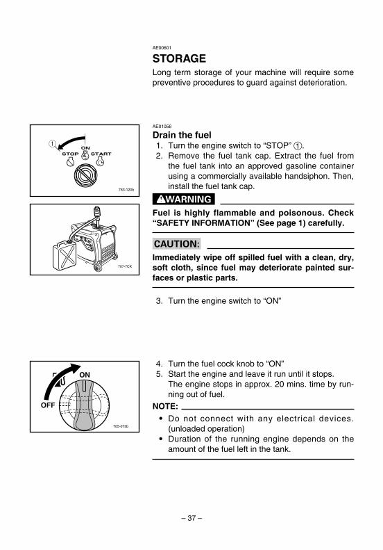
AE00601
STORAGELong term storage of your machine will require somepreventive procedures to guard against deterioration.
763-120b
q
707-7CK
705-073b
ON
OFF
AE01056
Drain the fuel1. Turn the engine switch to “STOP” 1.2. Remove the fuel tank cap. Extract the fuel from
the fuel tank into an approved gasoline containerusing a commercially available handsiphon. Then,install the fuel tank cap.
wFuel is highly flammable and poisonous. Check“SAFETY INFORMATION” (See page 1) carefully.
cCImmediately wipe off spilled fuel with a clean, dry,soft cloth, since fuel may deteriorate painted sur-faces or plastic parts.
3. Turn the engine switch to “ON”
4. Turn the fuel cock knob to “ON”5. Start the engine and leave it run until it stops.
The engine stops in approx. 20 mins. time by run-ning out of fuel.
NOTE:9 Do not connect with any electrical devices.
(unloaded operation)9 Duration of the running engine depends on the
amount of the fuel left in the tank.
7CK-28199-10_b 08.9.15 17:13 Page 37

– 38 –
6. Remove the bolts 1, and then pull outward on theareas of front cover 2 shown.
7. Drain the fuel from the carburetor by loosening thedrain screw 1 on the carburetor float chamber.
8. Turn the engine switch to “OFF”.9. Turn the fuel cock knob to “OFF”.
10. Tighten the drain screw.11. Install the front cover and tighten the bolts.
1
2
788-7CKa
1
707-7CKd
12. Tighten further if any bolts and nuts are loose.13. Store the generator in a dry, well-ventilated place,
with the cover placed over it.
7CK-28199-10_b 08.9.15 17:13 Page 38

– 39 –
AE00889
EnginePerform the following steps to protect the cylinder, pis-ton ring, etc. from corrosion.1. Remove the spark plug cap and spark plug, pour
about one tablespoon of SAE 10W30 or 20W40motor oil into spark plug hole and reinstall thespark plug only.
2. Turn the engine switch to “START” and crank theengine several seconds with ignition off to coat thecylinder walls with oil.
3. Clean exterior of the generator and apply a rustinhibitor.
4. Store the generator in a dry, well-ventilated place,with the cover placed over it.
712-7XF
788-7XFg
5. The generator must remain in a vertical positionwhen stored, carried or operated. The caster locklever should be in the “Lock” when stored or oper-ated.
7CK-28199-10_b 08.9.15 17:13 Page 39

– 40 –
762-003
AE01086
Battery1. Remove the battery.2. Store the battery in a cool, dark and dry place.
Do not store the battery in an excessively warm orcold place [i.e., less than 0°C (30°F) or more than30°C (90°F)].
w9 Disconnect the negative lead (black) first, then
the positive lead (red) from the battery.9 Connect the positive lead (red) first, then the
negative lead (black) to the battery wheninstalling the battery.
7CK-28199-10_b 08.9.15 17:13 Page 40

– 41 –
— MEMO —
7CK-28199-10_b 08.9.15 17:13 Page 41
– 42 –
707-7XFc
705-073
ON
OFF
q
700-006
760-009
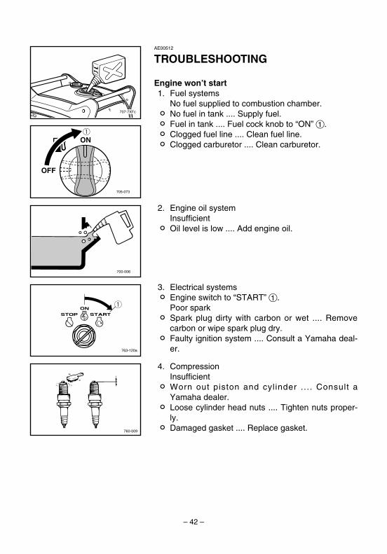
AE00512
TROUBLESHOOTING
Engine won’t start1. Fuel systems
No fuel supplied to combustion chamber.2 No fuel in tank .... Supply fuel.2 Fuel in tank .... Fuel cock knob to “ON” 1.2 Clogged fuel line .... Clean fuel line.2 Clogged carburetor .... Clean carburetor.
2. Engine oil systemInsufficient
2 Oil level is low .... Add engine oil.
3. Electrical systems2 Engine switch to “START” 1.
Poor spark2 Spark plug dirty with carbon or wet .... Remove
carbon or wipe spark plug dry.2 Faulty ignition system .... Consult a Yamaha deal-
er.
4. CompressionInsufficient
2 Worn out piston and cylinder .... Consult aYamaha dealer.
2 Loose cylinder head nuts .... Tighten nuts proper-ly.
2 Damaged gasket .... Replace gasket.
763-120a
q
7CK-28199-10_b 08.9.15 17:13 Page 42

– 43 –
AE00515
Generator won’t produce power• Safety device (AC protector) to “Reset”····Press the AC protector to “Set”.• The voltage select switch in the wrong position····Turn the voltage select switch to
the right position.
A ENGINE DOES NOT START
B Turn the engine switch to “ON”, then turnthe engine switch to “START”. And checkif the starter motor cranks.
C Cranks D Does not crank
F Turn the engine switch to “START”, andcheck if the oil warning light comes on.
G Does not come on H Comes on
L Turn the engine switch to “START” andcheck the spark plug for spark strength.(See “WARNING”).
w9 To prevent FIRE HAZARDS be
sure fuel is not present in thespark plug area.
9 To prevent FIRE HAZARDS besure to place the spark plugas far way as possible fromthe spark plug hole and car-buretor area.
9 To prevent ELECTRIC SHOCKdo not hold spark plug leadwith hand while testing.
M Engine does not start. N Engine starts.
R Check the following9 Fuel cock clogging9 Air cleaner element
clogging.
S Clogged
T OK
Clean or Replace; Consult aYamaha dealer.
U
V Consult a Yamaha dealer.
7CK-28199-10_b 08.9.15 17:13 Page 43

– 44 –
Faulty battery and/or starter motor.Consult a Yamaha dealer.
E
I Check engine oil level.
J OK K Level low
Consult a Yamaha dealer. Add engine oil.
O Check the spark plug.9 Type:9 Gap:
P Incorrect Q OK
Replace orAdjust gap.
Clean the sparkplug.
7CK-28199-10_b 08.9.15 17:13 Page 44

– 45 –
Unit EF6300iSDE
Type Air cooled 4-stroke gasoline OHVCylinder Arrangement Inclined, 1 cylinderDisplacement cm
3357
Bore × Stroke mm (in) 85.0 × 63.0 (3.35 × 2.48)Operation Hours Hr 5.1–13.3 (rated load–1/4 load)Fuel Unleaded gasolineFuel Tank Capacity L (US gal, Imp gal) 17.0 (4.49, 3.74)Engine Oil Quantity L (US qt, Imp qt) 1.3 (1.37, 1.14)Ignition System TCISpark Plug: Type BPR4ES (NGK)
Gap mm (in) 0.7–0.8 (0.028–0.031)Noise Level* dB (A) 64
AE00701
SPECIFICATIONSAE00702
DimensionsUnit EF6300iSDE
Overall Length mm (in) 780 (30.7)Overall Width mm (in) 616 (24.3)Overall Height mm (in) 692 (27.2)Dry Weight kg (lb) 91 (200)
AE00704
Engine
* : Measured at rated operation from 7 m (23 ft) distance.
AE00707
GeneratorUnit EF6300iSDE
AC OutputRated voltage V 120/240Rated frequency Hz 60Rated current A 45.8/22.9Rated output kVA 5.5Safety Device: Type Electronic + Mechanical (By metal)
BatteryUnit EF6300iSDE
Voltage V 12Capacity Ah 18
7CK-28199-10_b 08.9.15 17:13 Page 45

– 46 –
AE00012
Identification number recordsRecord your Primary I.D., and serial num-bers in the spaces provided, to assist youin ordering spare parts from a Yamahadealer.Also record and keep these I.D. numbersin a separate place in case your machineis stolen.
PRI-I.D. NUMBER:
PRI-I.D.CODE SERIAL No.
MODEL
Serial NO.
7CK–7CK-24163-00
790-7CKb
CONSUMER INFORMATION
AE00011
Machine identificationThe machine serial number is stamped inthe location as shown.
NOTE:The first three digits of these numbers arefor model identification; the remaining dig-its are the unit production number. Keep arecord of these numbers for referencewhen ordering parts from a Yamaha deal-er.
7CK-28199-10_b 08.9.15 17:13 Page 46

– 47 –
Yamaha Motor Corporation, U.S.A. hereby war-rants that new Yamaha consumer generators pur-chased from an authorized Yamaha consumergenerator dealer in the continental United Stateswill be free from defects in material and workman-ship for the period of time stated herein, subject tocertain stated limitations.
THE PERIOD OF WARRANTY Any new EF-series or EDL-series Yamaha Generator pur-chased for private, non-commercial use from anauthorized Yamaha consumer generator dealer inthe continental United States will be warranted against defects in material or work-manship for a period two (2) years from date ofpurchase, subject to exclusions noted herein. AnyYamaha non-commercial generator purchased and utilized for commercialor rental applications will be warranted for a periodone (1) year from the date of purchase, subject toexclusions noted herein.
DURING THE PERIOD OF WARRANTY anyauthorized Yamaha consumer generator dealerwill, free of charge, repair or replace, at Yamaha’soption, any part adjudged defective by Yamahadue to faulty workmanship or material from thefactory. Parts used in warranty repairs will be war-ranted for the balance of the product’s warrantyperiod. All parts replaced under warranty becomeproperty of Yamaha Motor Corporation U.S.A.
GENERAL EXCLUSIONS from this warranty shallinclude any failures caused by:a. Installation of parts or accessories that are not
qualitatively equivalent to genuine Yamahaparts.
b. Abnormal strain, neglect, or abuse.c. Lack of proper maintenance.d. Accident or collision damage.
SPECIFIC EXCLUSIONS from this warranty shallinclude parts replaced due to normal wear or rou-tine maintenance.
THE CUSTOMER’S RESPONSIBILITY under thiswarranty shall be to:1. Operate and maintain the generator as speci-
fied in the appropriate Owner’s Manual;
2. Give notice to an authorized Yamaha con-sumer generator dealer of any and all appar-ent defects within ten (10) days after discov-ery, and make the unit available at that timefor inspection and repairs at such dealer’splace of business.
WARRANTY TRANSFER: To transfer the warran-ty from the original purchaser to any subsequentpurchaser(s), it is imperative that the unit beinspected and registered for warranty by an autho-rized Yamaha consumer generator dealer. In orderfor this warranty to remain in effect, this inspectionand registration must take place within ten (10)days after transfer. An inspection and registrationfee will be charged for this service. In no case willthe warranty be extended beyond the original peri-od.
YAMAHA MOTOR CORPORATION, U.S.A. MAKESNO OTHER WARRANTY OF ANY KIND,EXPRESSED OR IMPLIED. ALL IMPLIED WAR-RANTIES OF MERCHANTABILITY AND FITNESSFOR A PARTICULAR PURPOSE WHICH EXCEEDTHE OBLIGATIONS AND TIME LIMITS STATED INTHIS WARRANTY ARE HEREBY DISCLAIMED BYYAMAHA MOTOR CORPORATION, U.S.A. ANDEXCLUDED FROM THIS WARRANTY.
SOME STATES DO NOT ALLOW LIMITATIONS ONHOW LONG AN IMPLIED WARRANTY LASTS, SOTHE ABOVE LIMITATION MAY NOT APPLY TOYOU. ALSO EXCLUDED FROM THIS WARRANTYARE ANY INCIDENTAL OR CONSEQUENTIALDAMAGES INCLUDING LOSS OF USE. SOMESTATES DO NOT ALLOW THE EXCLUSION ORLIMITATION OF INCIDENTAL OR CONSEQUEN-TIAL DAMAGES, SO THE ABOVE EXCLUSIONMAY NOT APPLY TO YOU.
THIS WARRANTY GIVES YOU SPECIFIC LEGALRIGHTS, AND YOU MAY ALSO HAVE OTHERRIGHTS WHICH VARY FROM STATE TO STATE.
YAMAHA MOTOR CORPORATION, U.S.A.Post Office Box 6555
Cypress, California 90630
AE01119
YAMAHA MOTOR CORPORATION U.S.A. EF- AND EDL-SERIES GENERATOR LIMITED WARRANTY
7CK-28199-10_b 08.9.15 17:13 Page 47

– 48 –
WARRANTY QUESTIONS AND ANSWERS
Q. What costs are my responsibility during thewarranty period?
A. The customer’s responsibility includes allcosts of normal maintenance service, non-warranty repairs, accident damages, as wellas oil and spark plugs.
Q. What are some examples of “abnormal” strain,neglect, or abuse?
A. These terms are general and overlap eachother in areas. Specific examples include:Running the machine out of oil; lack of propermaintenance; operating the machine with abroken or damaged part which causes anoth-er part to fail; and so on. If you have anyspecific questions on operation or mainte-nance, please contact your dealer for advice.
Q. Does the warranty cover incidental costs suchas transportation due to a failure?
A. No. The warranty is limited to repair of themachine itself.
Q. May I perform any or all of the recommendedmaintenance shown in the Owner’s Manualinstead of having the dealer do them?
A. Yes, if you are a qualified mechanic and followthe procedures specified in the Owner’s andService Manual. We do recommend, however,that items requiring special tools or equipmentbe done by a Yamaha generator dealer.
Q. Will the warranty be void or cancelled if I donot operate or maintain my new Yamahaexactly as specified in the Owner’s Manual?
A. No. The warranty on a new Yamaha cannotbe “voided” or “cancelled.”However, if a particular failure is caused byoperation or maintenance other than asshown in the Owner’s Manual, that failuremay not be covered under warranty.
Q. What responsibility does my dealer haveunder this warranty?
A. Each Yamaha generator dealer is expectedto:1. Check the operation of the generator
before sale.2. Explain the operation, maintenance, and
warranty requirements to your satisfactionat the time of sale, and upon your requestat any later date.
In addition, each Yamaha generator dealer isheld responsible for his setup, service andwarranty repair work.
Q. Is the warranty transferable to second own-ers?
A. Yes. The remainder of the existing warrantycan be transfered upon request.The unit has to be inspected and reregisteredby an authorized Yamaha generator dealer forthe policy to remain effective.
CUSTOMER SERVICE
If your machine requires warranty service, youmust take it to any authorized Yamaha generatordealer within the continental United States. Besure to bring your warranty registration identifica-tion or other valid proof of the original date of pur-chase. If a question or problem arises regardingwarranty, first contact the owner of the dealership.Since all warranty matters are handled at the deal-er level, this person is in the best position to helpyou. If you are still not satisfied and require addi-tional assistance, please write:
YAMAHA MOTOR CORPORATION U.S.A. CUSTOMER RELATIONS DEPARTMENT
P.O. BOX 6555Cypress, California 90630
CHANGE OF ADDRESS
The federal government requires each manufac-turer to maintain a complete, up-to-date list of allfirst purchasers against the possibility of a safety-related defect and recall. This list is compiled fromthe purchase registrations sent to Yamaha MotorCorporation, U.S.A. by the selling dealer at thetime of your purchase. If you should move afteryou have purchased your new generator, pleaseadvise us of your new address by sending a post-card listing your Yamaha model name, enginenumber, dealer number (or dealer’s name) as it isshown on your warranty identification, your nameand new mailing address. Mail to:
YAMAHA MOTOR CORPORATION, U.S.A.WARRANTY DEPARTMENT
P.O. Box 6555Cypress, California 90630
This will ensure that Yamaha Motor Corporation,U.S.A. has an up-to-date registration record inaccordance with federal law.
7CK-28199-10_b 08.9.15 17:13 Page 48

– 49 –
AE00789
EXHAUST EMISSION CONTROL SYSTEM AND COMPONENTS
Item Acronym9 CARB. ASSY., LH. & JT., ......................CARB (Carburetor)
CARBURETOR29 T.C.I. MAGNETO ASSY. & .....................EI (Electronic Ignition)
PLUG, SPARK9 CRANKCASE1 & HEAD, .......................PCV (Positive Crankcase
CYLINDER1 Ventilation)9 AIR FILTER ASSY. .................................ACL (Air Cleaner)9 MUFF., 2, CAP, NET, WIRE2 &
ARRESTER, SPARK
The above items and the corresponding acronyms are provided in accordance with U.S.EPA REGULATIONS FOR NEW NONROAD SPARK-IGNITION NONHANDHELDENGINES and the CALIFORNIA REGULATIONS FOR 1995 AND LATER SMALL OFF-ROAD ENGINES.The acronyms conform to the latest version of the SAE’s recommended practice docu-ment J1930, “Diagnostic Acronyms, Terms, and Definitions For Electrical/ElectronicSystem”.
It is recommended that these items be serviced by a Yamaha dealer.
7CK-28199-10_b 08.9.15 17:13 Page 49

– 50 –
— MEMO —
7CK-28199-10_b 08.9.15 17:13 Page 50
– 51 –
M
YR
B/W
L/R
R/W
R/B
B
OFF
ON
ST
AR
T
R
R
B
B
G/W B/R
R/W
Or/
W
Y/W
RY
YYY
YY
Y
G L Or
G/W
B/R
L/Y
L/R
L/W
Y/W
R/W
L/W
Or/
W
R RBr
Or
LG
PY
Or
LG
PY
Br
Or
LY
G
Or
Br
LG
Y
R Y G B PB
P
Br
R R B Y
Br
LYYYY
R/Y
B/Y
GOr
R LYG Or
L/W
G/W
R/W
Or/
W
Y/W
L/W
L
L
Or
WWW
W
WWW
YYY
YY
Y
B P
B/Y
R/Y
YYYY G
B BRRW
WW
WWW G
/R
WG
/R
B/W
Or
B/W
Or
B/W
L/Y
B/R
L/Y
L YOr
L/W
R/W
R/W
Y/W R/L
R/B
L/G
B/W
Br/
W
Br/
W
R/W
G/Y
G/Y
G/Y
G/R Y
G/R Y
L/W
G/Y
L/W
G/Y
L/R
G/RR
Or
YR
/B
R/W
B/W Y
R/B
R/W
B
L/RR
W
R/B
G/Y
G/R
Y/W
L/W L/G
G/Y
R/L
Y BR
B/W
R Br
G/Y
G/Y
L/R
R/B
R/W
B/W
Y
B/YBR
R/Y
L/G
G/Y
R/L
B/W
Y B/W
Y/W
L/W W
G/R
G/Y
R/B
Y
YY L
G/R
G/Y
L/W
Y
G/R
G/Y
L/W
G/Y
B/W
RG
/Y
RR
G/R
L/R
R/B
G/Y
YR Or
R/W
R/W
G/Y
R
2 p o
g
k
jf
s
dh
z ; lxc1
34
5 56 7 7
89
q
0
w
e r t
y u
ai
AE
0075
1
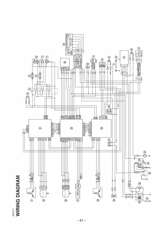
WIR
ING
DIA
GR
AM
7CK-28199-10_b 08.9.15 17:13 Page 51
– 52 –
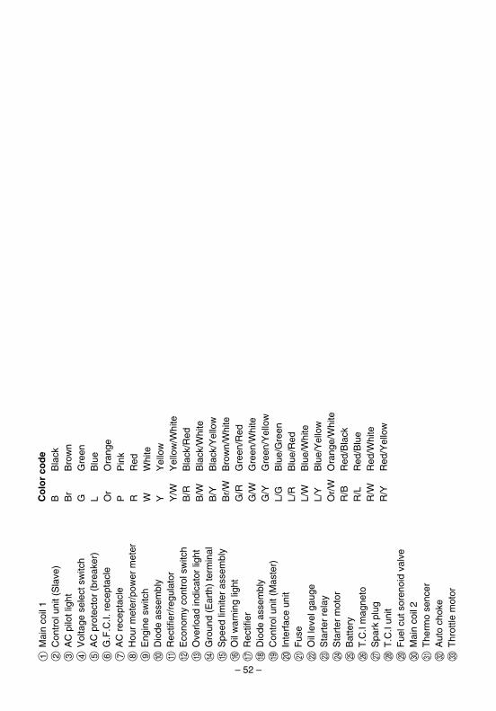
1M
ain
coil
12
Con
trol
uni
t (S
lave
)3
AC
pilo
t lig
ht4
Vol
tage
sel
ect s
witc
h5
AC
pro
tect
or (
brea
ker)
6G
.F.C
.I. r
ecep
tacl
e7
AC
rec
epta
cle
8H
our
met
er/p
ower
met
er9
Eng
ine
switc
h0
Dio
de a
ssem
bly
qR
ectif
ier/
regu
lato
rw
Eco
nom
y co
ntro
l sw
itch
eO
verlo
ad in
dica
tor
light
rG
roun
d (E
arth
) te
rmin
alt
Spe
ed li
mite
r as
sem
bly
yO
il w
arni
ng li
ght
uR
ectif
ier
iD
iode
ass
embl
yo
Con
trol
uni
t (M
aste
r)p
Inte
rfac
e un
ita
Fus
es
Oil
leve
l gau
ged
Sta
rter
rel
ayf
Sta
rter
mot
org
Bat
tery
hT
.C.I
mag
neto
jS
park
plu
gk
T.C
.I un
itl
Fue
l cut
sor
enoi
d va
lve
;M
ain
coil
2z
The
rmo
senc
erx
Aut
o ch
oke
cT
hrot
tle m
otor
Co
lor
cod
eB
Bla
ckB
rB
row
nG
Gre
enL
Blu
eO
rO
rang
eP
Pin
kR
Red
WW
hite
YY
ello
wY
/WY
ello
w/W
hite
B/R
Bla
ck/R
edB
/WB
lack
/Whi
teB
/YB
lack
/Yel
low
Br/
WB
row
n/W
hite
G/R
Gre
en/R
edG
/WG
reen
/Whi
teG
/YG
reen
/Yel
low
L/G
Blu
e/G
reen
L/R
Blu
e/R
edL/
WB
lue/
Whi
teL/
YB
lue/
Yel
low
Or/
WO
rang
e/W
hite
R/B
Red
/Bla
ckR
/LR
ed/B
lue
R/W
Red
/Whi
teR
/YR
ed/Y
ello
w
7CK-28199-10_b 08.9.15 17:13 Page 52

– 53 –
— MEMO —
7CK-28199-10_b 08.9.15 17:13 Page 53

7CK-28199-10_hyoshi 08.8.30 14:27 Page 2

Generator
7CK-28199-10
EF6300iSDE
OWNER’S MANUAL
PLEASE READ AND UNDERSTAND THIS MANUALCOMPLETELY BEFORE OPERATING THE MACHINE.
LIT-19626-01-52PRINTED ON RECYCLED PAPER
PRINTED IN JAPAN2008 909 – 1.0 × 1 !
7CK-28199-10_hyoshi 08.8.30 14:27 Page 1