Generator OS43024
333
-
Upload
franciscosiprotec -
Category
Documents
-
view
385 -
download
29
description
Manual
Transcript of Generator OS43024


Copyright 2008 ABB. All rights reserved.
Type des. Prod. class: Part no.
Prep. Annelie Kruse 2008-03-12 Doc. kind Instruction No. of p.
Appr. Flood Mats A 2008-05-09Resp. dept AP/MMO Approved
Title Mounting of cooling top 3
Doc. no. Lang. Rev. ind. Page
ABB AB, Machines 3BSM001483-A en 1
FILE: 3BSM001483-A en.doc; TEMPLATE: TECHN_DOC_STAND_P.dot -; SKELETON: ; SAVEDATE: 2008-03-13 14:16
Working procedure of assembly and disassembly of cooler top:
1. Loosen and remove the bolts holding the flat protection plate on top of the machine and lift it off.
2. Observe the rubber hoses attached to the stator end plates. Loosen them, but do not drop them into the machine.
3. Place the cooler housing with coolers on top of the machine with a gap 10-20cm between the cooler housing and machine.
4. Connect the rubber hoses, for leakage water, to the connections on the cooler drainers and tighten the hose clamps.
5. Lower the cooler housing on to the machine and tighten the bolts holding it to the side panels. Be careful NOT to drop any bolts or nuts into the machine.
Re-assembly the cooler top in the reverse order as describe.
Rubber hoses for leakage water to be disconnected.4-legs lift Cooler housing
3) 5) 2) 1)
4)Lifting-device shall only be used when lifting the cooler housing.
Alternative 1
Max 90o
D=30, Ellipsed
Lifting hook’s position towards lifting device
Doc. no. Lang. Rev. ind. Page
ABB AB, Machines 3BSM001483-A en 2
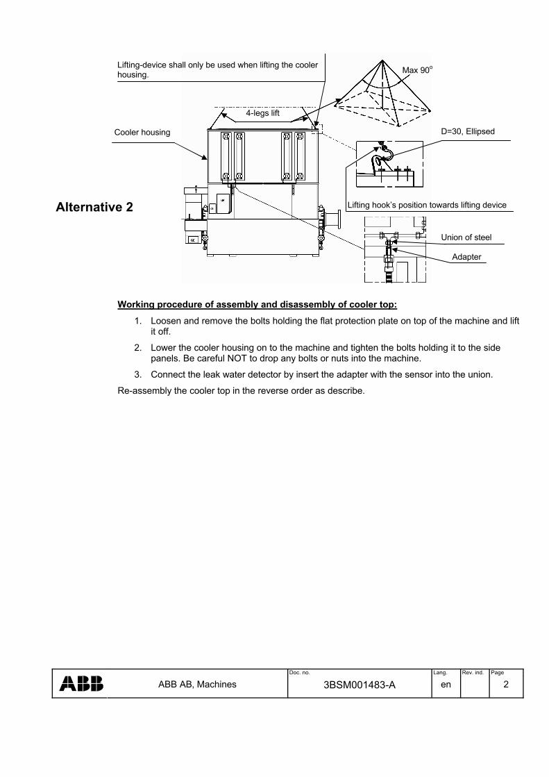
Working procedure of assembly and disassembly of cooler top:
1. Loosen and remove the bolts holding the flat protection plate on top of the machine and lift it off.
2. Lower the cooler housing on to the machine and tighten the bolts holding it to the side panels. Be careful NOT to drop any bolts or nuts into the machine.
3. Connect the leak water detector by insert the adapter with the sensor into the union.
Re-assembly the cooler top in the reverse order as describe.
4-legs lift
Cooler housing
Lifting-device shall only be used when lifting the cooler housing. Max 90o
Union of steel
Adapter
Alternative 2 Lifting hook’s position towards lifting device
D=30, Ellipsed

Doc. no. Lang. Rev. ind. Page
ABB AB, Machines 3BSM001483-A en 3
REVISION
Rev. ind. Page (P) Chapt. (C)
Description Date Dept./Init.

Service & repair
Dismantling and assembly of PMG-stator
Document No.: 3BSM 005438
Contents1.1 General safety instructions ............................................ 3
2.1 Dismantling of PMG stator............................................ 42.2 Assembly of PMG stator ..............................................112.3 Recommended tightening torque for bolts on the
machine........................................................................ 17
3BSM 005438 ii
3BS
M 0
0543
8, R
ev.
B E
N -
The information in this document is subject to change without notice and should not be construed as a commitment by ABB. ABB assumes no responsibility for any errors that may appear in this document.
In no event shall ABB be liable for direct, indirect, special, incidental or consequential damages of any kind arising from the use of this document, nor shall ABB be liable for incidential or consequential damages arising from the use of any software or hardware described in this document.
This document and parts thereof must not be reproduced or copied without ABB’s written permission, and the contents thereof must not be imparted to a third party nor be used for any unauthorized purpose.
©Copyright 2001 ABB. All rights reserved.

3BSM 005438 3
3BS
M 0
054
38, R
ev. B
EN
-
The procedures described in this manual are only to be performed by trained personnel authorized by the user.
The manufacturer is not responsible for malfunctions that comprise safety as a result of alteration, use of non ABB replacement parts, neglect or misuse.
Replacement parts may vary from those shown in this manual. Should you have questions on those parts please contact ABB Automation Technologies AB.
The actual appearance of the machine may vary from the illustration in this manual.
Should pre-owned ABB equipment be purchased and reconditioned, the equipment should not be used until testing and analysis demonstrate that the equipment meet the original or upgraded specifications.
The use of solvents as cleaning agents and the use of lubricants can involve health and/or safety hazards. The recommended precautions and procedures of the manufacturers should be followed.
3BS
M 0
054
38, R
ev. B
EN
-
! "#
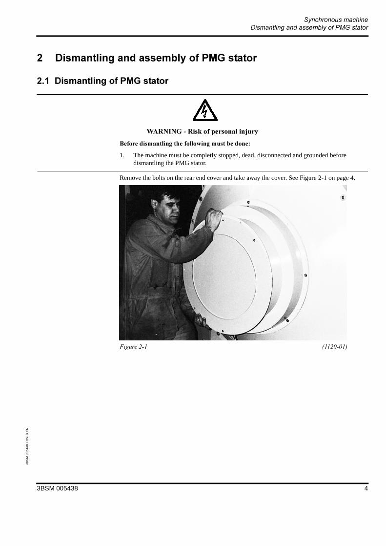
1. The machine must be completly stopped, dead, disconnected and grounded before dismantling the PMG stator.
Remove the bolts on the rear end cover and take away the cover. See Figure 2-1 on page 4.
3BSM 005438 4

3BS
M 0
054
38, R
ev. B
EN
-
Remove the cable from the earth fault brush holder and disconnect the cable from the cable clamps of the sheet metal housing for PMG stator. See Figure 2-2 on page 5.
Remove the brushes and the brush holder in accordance with Figure 2-3 on page 5.
3BSM 005438 5
3BS
M 0
054
38, R
ev. B
EN
-
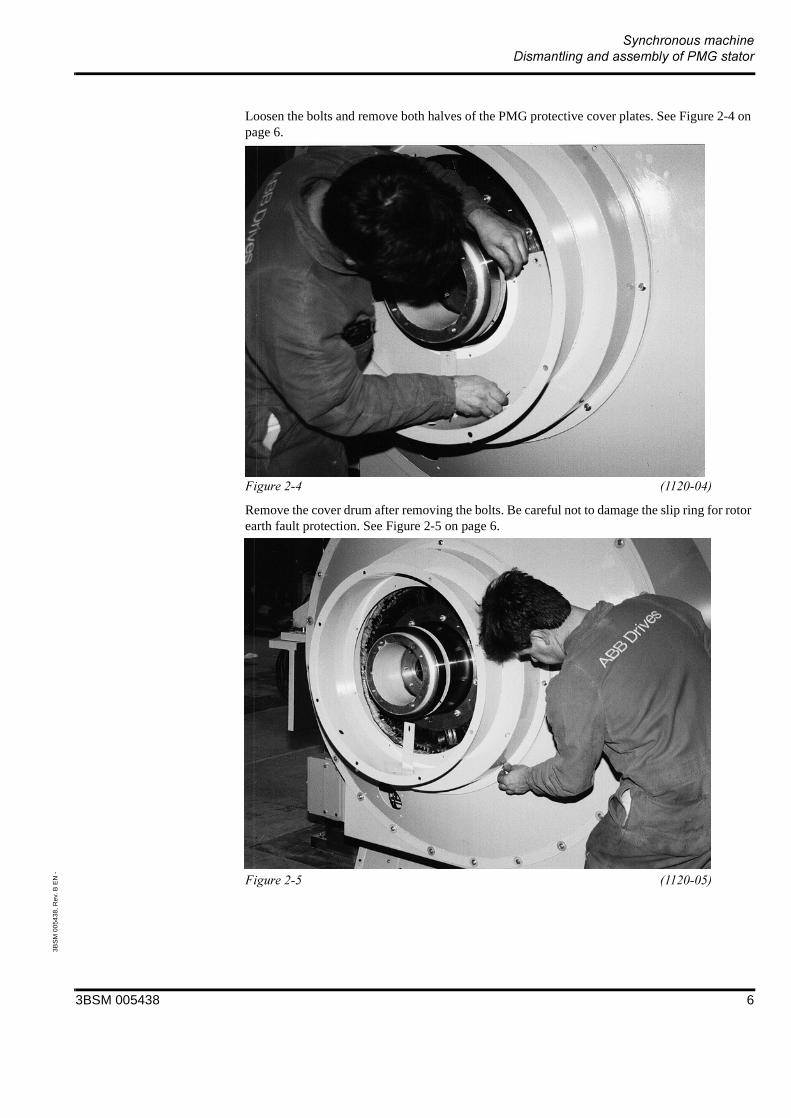
Loosen the bolts and remove both halves of the PMG protective cover plates. See Figure 2-4 on page 6.
Remove the cover drum after removing the bolts. Be careful not to damage the slip ring for rotor earth fault protection. See Figure 2-5 on page 6.
3BSM 005438 6

3BS
M 0
054
38, R
ev. B
EN
-
Remove the PMG stator cables from the terminal block. See Figure 2-6 on page 7.
Place a sheet of stiff paper or plastic in the air gap around the rotor as shown in Figure 2-7 on page 7.
3BSM 005438 7

3BS
M 0
054
38, R
ev. B
EN
-
Attach a lifting chain to the PMG stator housing and remove the bolts. See Figure 2-8 on page 8.
$ %
& "! '& (
Insert the tip of a large screw driver between the housing flange and the exciter stator housing and break loose the PMG stator housing which is held in place firmly by sealing compound.
3BSM 005438 8

3BS
M 0
054
38, R
ev. B
EN
-
Lift away the PMG housing carefully with the crane. See Figure 2-9 on page 9.
3BSM 005438 9

3BS
M 0
054
38, R
ev. B
EN
-
) &&
* &&"! %)(
1. Be extremely careful when moving the PMG stator housing to aviod damage to components due to magnetic forces.
2. Remove you wrist watch, credit cards and other digital equipment before working around those magnetic forces.
3. Personnel with pace maker should not be working in the vicinity of the PMG.
Now you are ready for changing diodes or thyristor according to section “Dismantling and assembly of diodes and thyristor. See Figure 2-10 on page 10
3BSM 005438 10
3BS
M 0
0543
8, R
ev.
B E
N -
) &&
%) *( && (
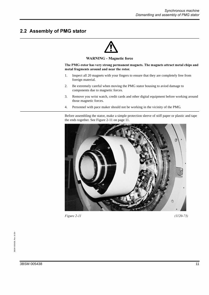
1. Inspect all 20 magnets with your fingers to ensure that they are completely free from foreign material.
2. Be extremely careful when moving the PMG stator housing to aviod damage to components due to magnetic forces.
3. Remove you wrist watch, credit cards and other digital equipment before working around those magnetic forces.
4. Personnel with pace maker should not be working in the vicinity of the PMG.
Before assembling the stator, make a simple protection sleeve of stiff paper or plastic and tape the ends together. See Figure 2-11 on page 11.
3BSM 005438 11

3BS
M 0
0543
8, R
ev.
B E
N -
Check that the wires from the PMG stator are correctly strapped to the bracket as shown in Figure 2-12 on page 12.
3BSM 005438 12
3BS
M 0
0543
8, R
ev.
B E
N -
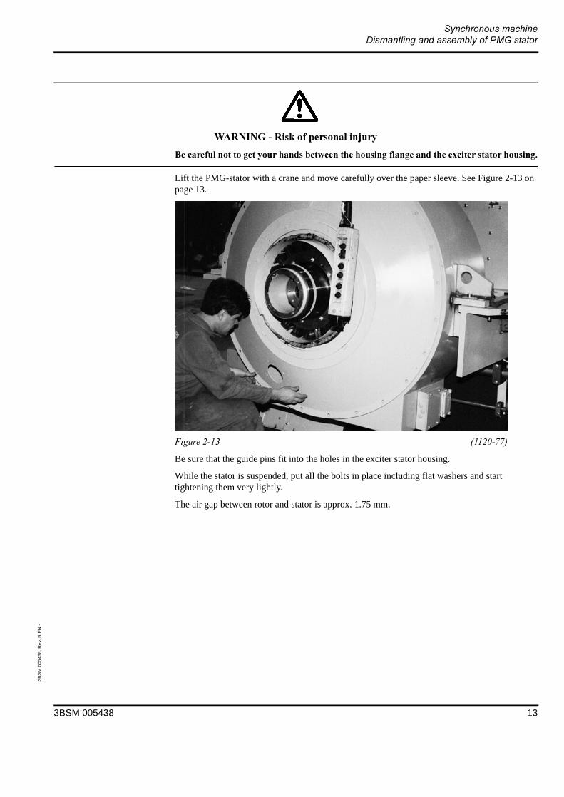
& "! '& (
Lift the PMG-stator with a crane and move carefully over the paper sleeve. See Figure 2-13 on page 13.
Be sure that the guide pins fit into the holes in the exciter stator housing.
While the stator is suspended, put all the bolts in place including flat washers and start tightening them very lightly.
The air gap between rotor and stator is approx. 1.75 mm.
3BSM 005438 13
3BS
M 0
0543
8, R
ev.
B E
N -
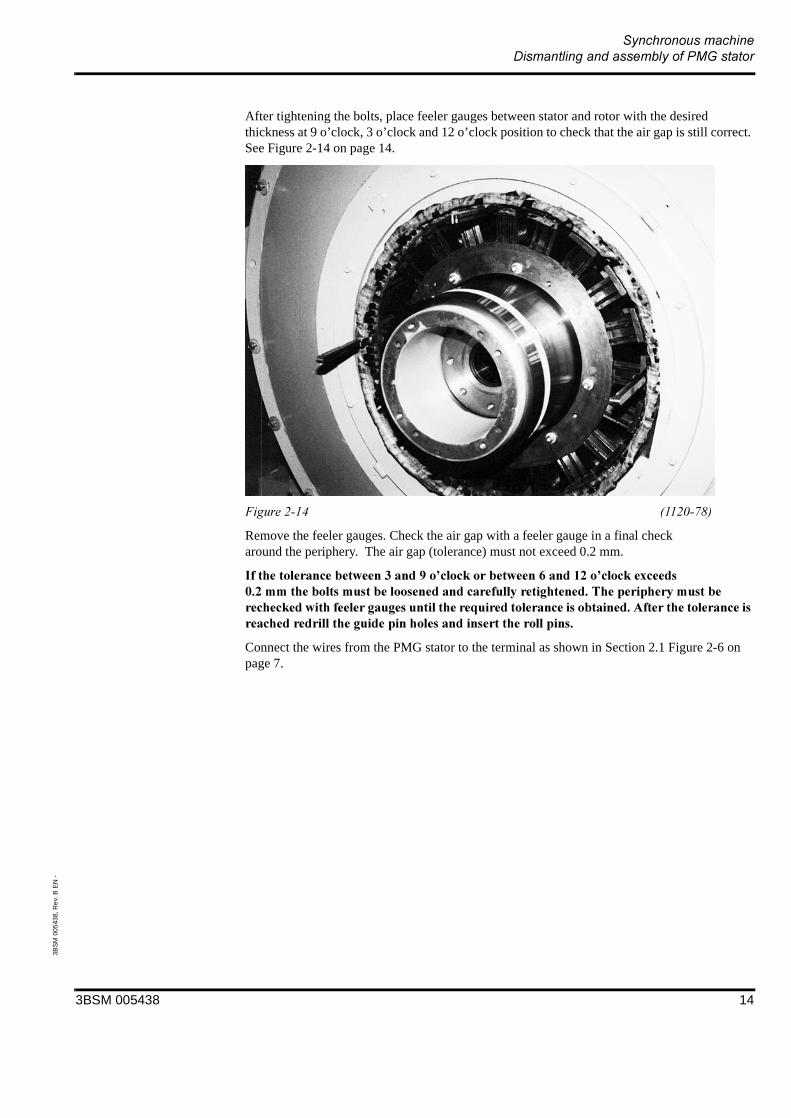
After tightening the bolts, place feeler gauges between stator and rotor with the desired thickness at 9 o’clock, 3 o’clock and 12 o’clock position to check that the air gap is still correct. See Figure 2-14 on page 14.
Remove the feeler gauges. Check the air gap with a feeler gauge in a final check around the periphery. The air gap (tolerance) must not exceed 0.2 mm.
&"!+,-&&"!./0-&&'&1(0 ""& ( "& &! 2 & " ( & & (
Connect the wires from the PMG stator to the terminal as shown in Section 2.1 Figure 2-6 on page 7.
3BSM 005438 14

3BS
M 0
0543
8, R
ev.
B E
N -
Take one half of the protective cover plate and slide it behind the brush holder mounting bracket. Insert a bolt loosely. Take the other half and place it on top. Attach two bolts to assemble the two halves. Insert all the other bolts on the periphery. Tighten these carefully with a pinch bar while checking visually that the white plastic ring does not touch the rotating shaft extension (sleeve). See Figure 2-15 on page 15.
Adjust the two brush arms so that the angle between the inserted brush and the centre line of the rotor is 90 degree. See Figure 2-16 on page 15 and Figure 2-17 on page 16.
3BSM 005438 15

3BS
M 0
0543
8, R
ev.
B E
N -
.
Insert the brushes and connect the leads to the brass plate below.
Connect the cable from box GL.
Replace the rear end cover and tighten all bolts.
90o
3BSM 005438 16

3BS
M 0
0543
8, R
ev.
B E
N -
Recommended tightening torque for bolts, property class 8.8, slightly coated with oil.
# 3)" 45)&6(
! " # $
% (Nm)(lbft)
22.516.6
4533
7958
! " & $ ' $
% (Nm)(lbft)
190140
420300
735550
15001100
3BSM 005438 17

3BSM 005438
2003-01-15

Service & repair
Dismantling and assembly of exciter stator
Document No.:3BSM 005439
Contents
1.1 General safety instructions .........................32.1 Removal of the exciter stator ......................4
2.2 Assembly of exciter stator ........................10
2.3 Recommended tightening torque for bolts11

3B
SM
005
439
, Rev
. B E
N -
The information in this document is subject to change without notice and should not be construed as a commitment by ABB. ABB assumes no responsibility for any errors that may appear in this document.
In no event shall ABB be liable for direct, indirect, special, incidental or consequential damages of any kind arising from the use of this document, nor shall ABB be liable for incidential or consequential damages arising from the use of any software or hardware described in this document.
This document and parts thereof must not be reproduced or copied without ABB’s written permission, and the contents thereof must not be imparted to a third party nor be used for any unauthorized purpose.
©Copyright 2001 ABB. All rights reserved.
3BSM 005439 -ii

3BSM 005439 3
3BS
M 0
054
39, R
ev. B
EN
-
The procedures described in this manual are only to be performed by trained personnel authorized by the user.
The manufacturer is not responsible for malfunctions that comprise safety as a result of alteration, use of non ABB replacement parts, neglect or misuse.
Replacement parts may vary from those shown in this manual. Should you have questions on those parts please contact ABB Automation Technologies AB.
The actual appearance of the machine may vary from the illustration in this manual.
Should pre-owned ABB equipment be purchased and reconditioned, the equipment should not be used until testing and analysis demonstrate that the equipment meet the original or upgraded specifications.
The use of solvents as cleaning agents and the use of lubricants can involve health and/or safety hazards. The recommended precautions and procedures of the manufacturers should be followed.
3B
SM
005
439,
Rev
. B E
N -
!"#$
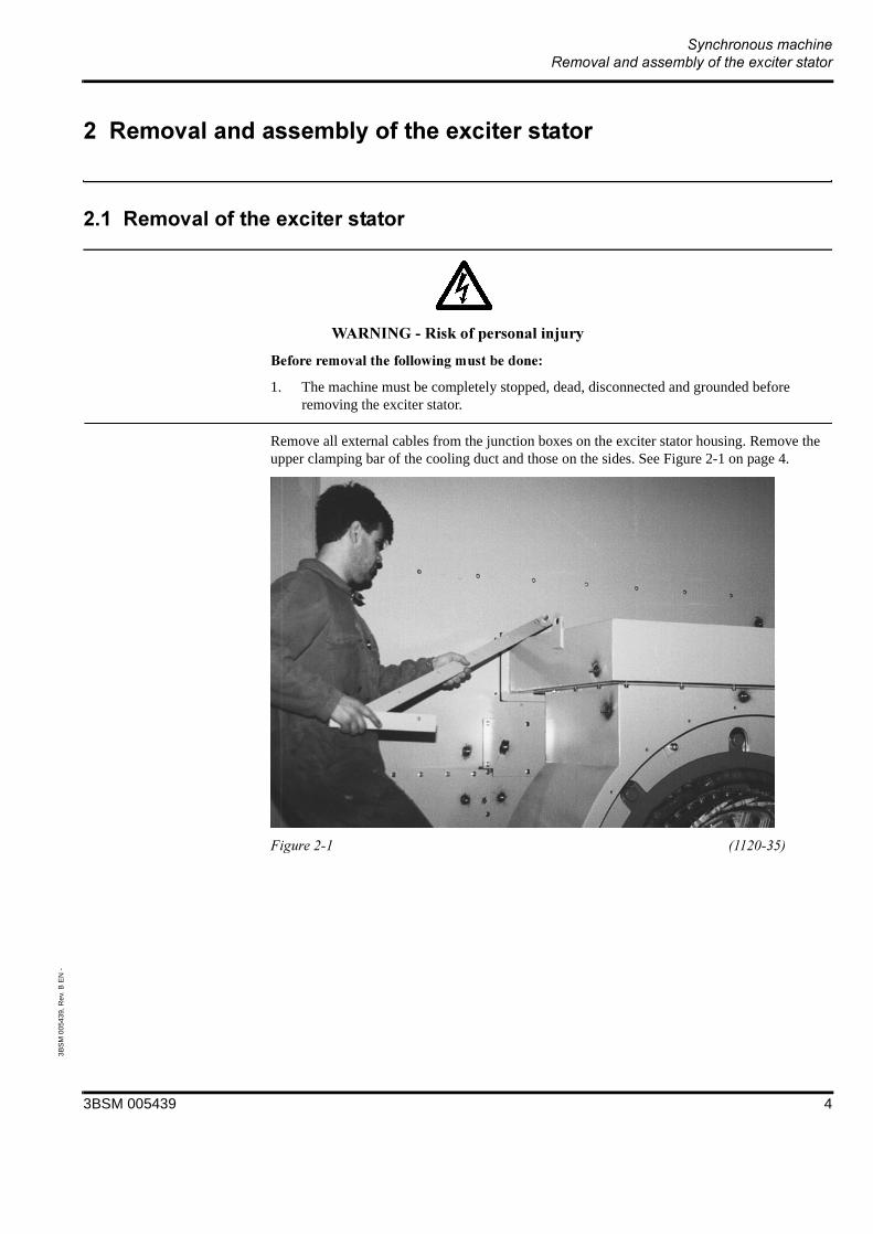
1. The machine must be completely stopped, dead, disconnected and grounded before removing the exciter stator.
Remove all external cables from the junction boxes on the exciter stator housing. Remove the upper clamping bar of the cooling duct and those on the sides. See Figure 2-1 on page 4.
3BSM 005439 4
3B
SM
005
439,
Rev
. B E
N -
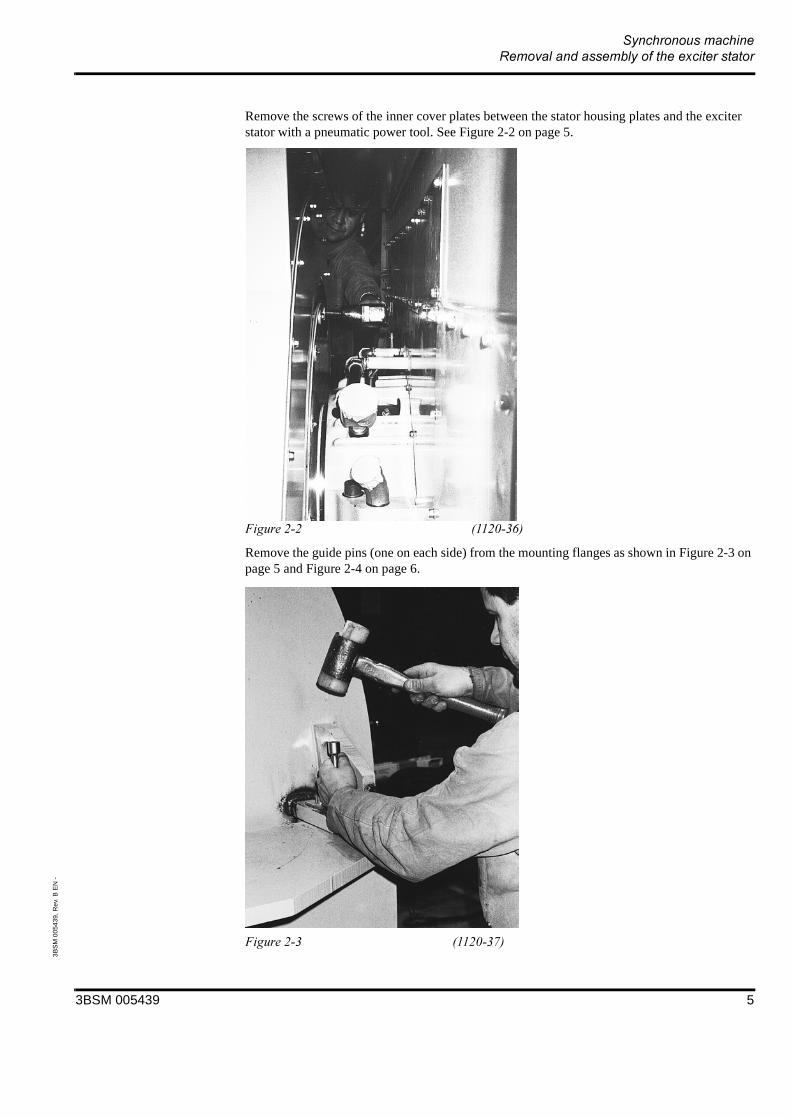
Remove the screws of the inner cover plates between the stator housing plates and the exciter stator with a pneumatic power tool. See Figure 2-2 on page 5.
Remove the guide pins (one on each side) from the mounting flanges as shown in Figure 2-3 on page 5 and Figure 2-4 on page 6.
3BSM 005439 5

3B
SM
005
439,
Rev
. B E
N -
Remove the four M16 hex. head socket cap screws, (two on each side) with the socket wrench using a pipe extension. See Figure 2-5 on page 6.
3BSM 005439 6

3B
SM
005
439,
Rev
. B E
N -
%
&' (
1. Use lifting equipment that is appropriate for the load, see TBA for weight.
Place a pipe or steel rod through the lifting eyes, attach a lifting strap between the welded lifting eyes and the iron rod or pipe as shown, and carefully try to lift the unit. See Figure 2-6 on page 7.
3BSM 005439 7

3B
SM
005
439,
Rev
. B E
N -
Check the centre of gravity and adjust the straps, test carefully until the unit can be lifted straight up without tipping to the rear or to the front. See Figure 2-7 on page 8.
Having lifted the unit, slide the unit axially away from the generator and put it on two wooden blocks. See Figure 2-8 on page 8 and Figure 2-9 on page 9.
3BSM 005439 8

3B
SM
005
439,
Rev
. B E
N -
Each set of brass shims must be held together, marked and stored so that they are returned to the same side when reassembling the stator housing.
3BSM 005439 9
3B
SM
005
439,
Rev
. B E
N -
Place a pipe or steel rod through the lifting eyes, attach a lifting strap between the welded lifting eyes and the iron rod or pipe as shown and carefully lift the unit. See Figure 2-6 on page 7 in Section 2.1.
Check the centre of gravity and adjust the straps, test carefully until the unit can be lifted straight up without tipping to the rear or to the front.
Having lifted the unit, slide the unit axially and very carefully over the rotor. See Figure 2-7 on page 8 in Section 2.1.
Place the same shims under the stator housing feet. Replace the guide pins and the bolts. Check the air gap.
Assemble the inner cover plates between the generator housing and the exciter stator housing. See Figure 2-2 on page 5 in Section 2.1.
Assemble the clamping bars for the cooling duct. See Figure 2-1 on page 4 in Section 2.1.
Assemble all external cables.
3BSM 005439 10

3B
SM
005
439,
Rev
. B E
N -
Recommended tightening torque for bolts property class 8.8, slightly coated with oil.
$ )*"## #+,*'-(
! "# "$ "
% (Nm)(lbft)
22.516.6
4533
7958
! "& "$ "' "$
% (Nm)(lbft)
190140
420300
735550
15001100
3BSM 005439 11

3BSM 005439
2003-01-15
Service & Repair Dismantling and assembly of bearings
Document No.: 3BSM 005446
Contents1.1 General safety instructions .........................3
2.1 Dismantling of bearings..............................4
2.2 Change of bearing liner ............................15
2.3 Assembly of bearings ...............................21
2.4 Recommended tightening torquefor bolts .....................................................30

3BSM 005446 ii
3BS
M 0
0544
6, R
ev.
B E
N -
The information in this document is subject to change without notice and should not be construed as a commitment by ABB. ABB assumes no responsibility for any errors that may appear in this document.
In no event shall ABB be liable for direct, indirect, special, incidental or consequential damages of any nature or kind arising from the use of this document, nor shall ABB be liable for incidental or consequential damages arising from use of any software or hardware described in this document.
This document and parts thereof must not be reproduced or copied without ABB’s written permission, and the contents thereof must not be imparted to a third party nor be used for any unauthorized purpose.
©Copyright 2001 ABB. All rights reserved.

3BSM 005446 3
3BS
M 0
0544
6, R
ev.
B E
N -
The procedures described in this manual are only to be performed by trained personnel authorized by the user.
The manufacturer is not responsible for malfunctions that comprise safety as a result of alteration, use of non ABB replacement parts, neglect or misuse.
Replacement parts may vary from those shown in this manual. Should you have questions on those parts please contact ABB Automation Technologies AB.
The actual appearance of the machine may vary from the illustration in this manual.
Should pre-owned ABB equipment be purchased and reconditioned, the equipment should not be used until testing and analysis demonstrate that the equipment meet the original or upgraded specifications.
The use of solvents as cleaning agents and the use of lubricants can involve health and/or safety hazards. The recommended precautions and procedures of the manufacturers should be followed.

3BS
M 0
0544
6, R
ev.
B E
N -
! "#
1. The machine must be completely stopped, dead, disconnected and grounded before dismantling the bearing.
Before starting the dismantling of the bearing, rotate the rotor so that the poles are at 90 degrees to the vertical.
Loosen all cables from the cable brackets.
Remove the tubes from the air-lock seal, see Figure 2-1 on page 4.
Loosen the cable from the vibration detector and remove the vibration probes.
If lower half of the bearing shell will be removed from the bearing housing, the temperature probes has to be dismantled from the bearing housing. See Figure 2-2 on page 5
" " " " $ "% " ! "% &.
Tubes from air-lock seal
3BSM 005446 4
3BS
M 0
0544
6, R
ev.
B E
N -
Disconnect the tubes between the run-out tanks and the upper halves of the bearing.
Disconnect the level-indicators on the run-out tanks.
Remove the cooler top and the sheet metal end covers around the bearing and the part including the run-out tank if such exist. Remove even the cooling duct for the exciter at the ND-end if both bearings are to be inspected or repaired.
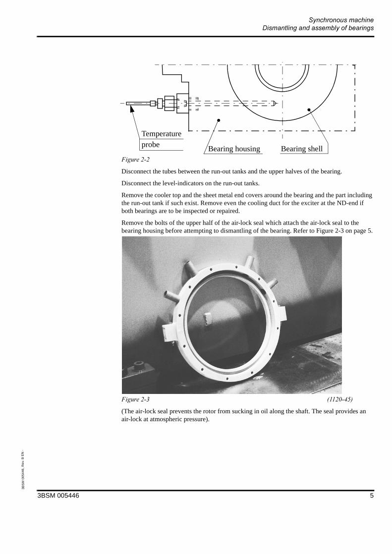
Remove the bolts of the upper half of the air-lock seal which attach the air-lock seal to the bearing housing before attempting to dismantling of the bearing. Refer to Figure 2-3 on page 5.
(The air-lock seal prevents the rotor from sucking in oil along the shaft. The seal provides an air-lock at atmospheric pressure).
Bearing shellBearing housing
Temperature probe
3BSM 005446 5

3BS
M 0
0544
6, R
ev.
B E
N -
To be sure not to destroy the air-lock seal, remove the upper half by removing two bolts. See Figure 2-4 on page 6.
Loosen and remove the eight M24 hex. head socket bolts in the upper half of the bearing housing. See Figure 2-5 on page 6.
3BSM 005446 6

3BS
M 0
0544
6, R
ev.
B E
N -
Insert a lifting eye and carefully lift the upper half away from the lower half. See Figure 2-6 on page 7.
3BSM 005446 7
3BS
M 0
0544
6, R
ev.
B E
N -
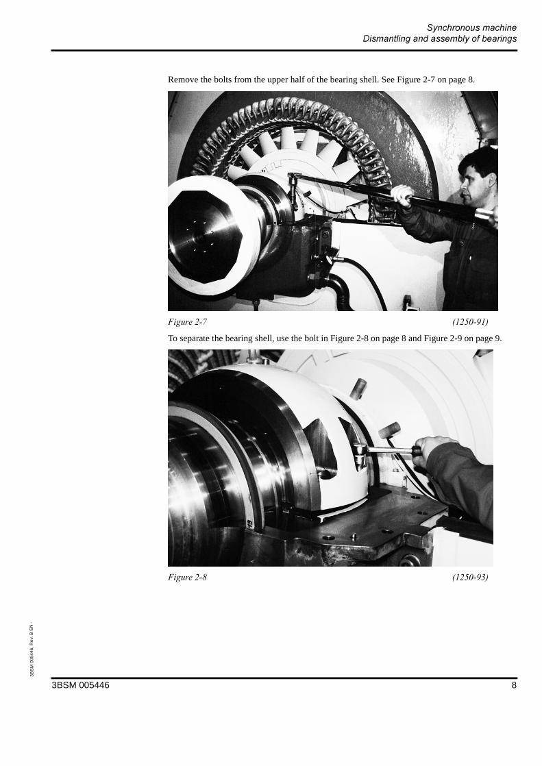
Remove the bolts from the upper half of the bearing shell. See Figure 2-7 on page 8.
To separate the bearing shell, use the bolt in Figure 2-8 on page 8 and Figure 2-9 on page 9.
3BSM 005446 8

3BS
M 0
0544
6, R
ev.
B E
N -
Insert a lifting eye and lift away the upper bearing shell. See Figure 2-10 on page 9.
This bolt is for used to separate the
two halves of the bearing shell.
3BSM 005446 9
3BS
M 0
0544
6, R
ev.
B E
N -
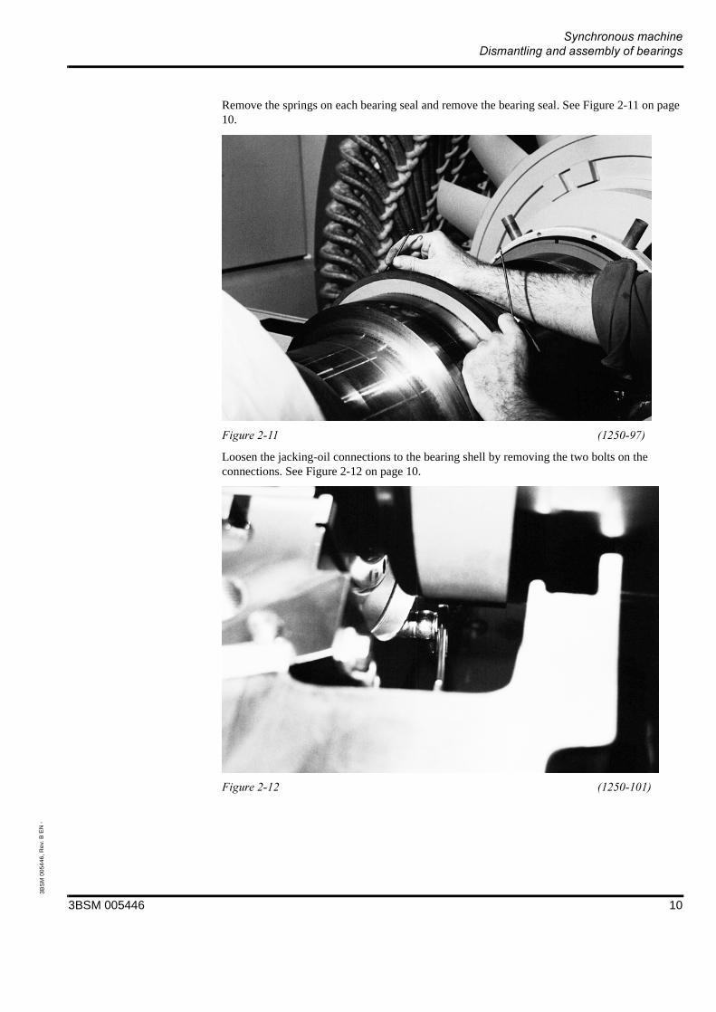
Remove the springs on each bearing seal and remove the bearing seal. See Figure 2-11 on page 10.
Loosen the jacking-oil connections to the bearing shell by removing the two bolts on the connections. See Figure 2-12 on page 10.
3BSM 005446 10
3BS
M 0
0544
6, R
ev.
B E
N -
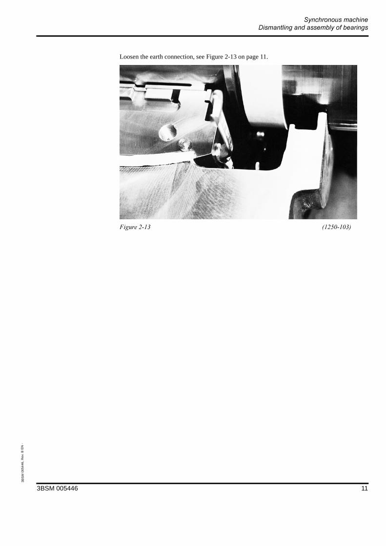
Loosen the earth connection, see Figure 2-13 on page 11.
3BSM 005446 11

3BS
M 0
0544
6, R
ev.
B E
N -
Place a magnetic foot with a dial indicator so that the indicator can measure a vertical movement (lift) of the rotor as shown in Figure 2-14 on page 12. Place a hydraulic jack (30 ton lifting capacity) underneath the rotor shaft as shown and lift the rotor 0.3-0.4 mm.
' ! "%() ! ( " ( *
3BSM 005446 12

3BS
M 0
0544
6, R
ev.
B E
N -
Place two distance elements in the air gap between the rotor poles and the stator. Attach 2 lifting eyes into the lower half of the bearing shell as shown in Figure 2-15 on page 13 and draw the assembly toward you so that it slides around the journal, with use of a hand-ratchet.
Insert a lifting eye as shown in Figure 2-16 on page 13 and remove the lower bearing shell, see Figure 2-17 on page 14. Be careful.
3BSM 005446 13
3BS
M 0
0544
6, R
ev.
B E
N -
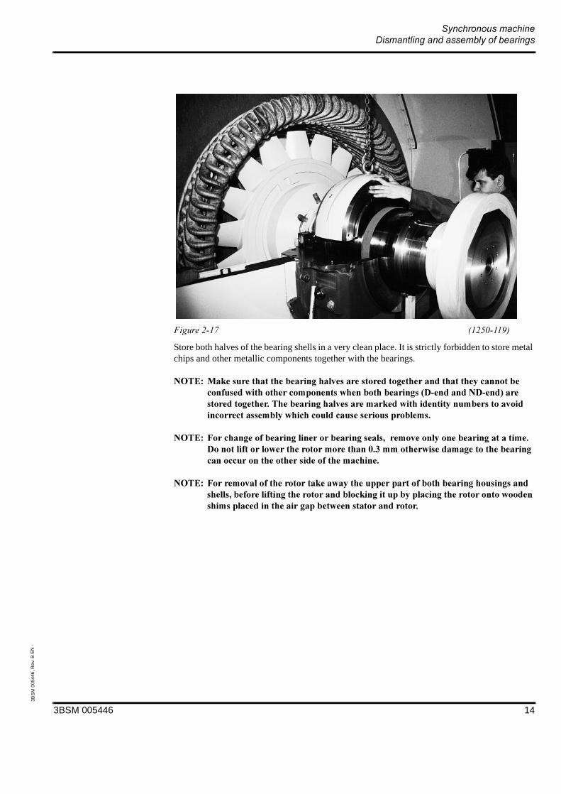
Store both halves of the bearing shells in a very clean place. It is strictly forbidden to store metal chips and other metallic components together with the bearings.
# + " % ("(! (! " " $''& * " %! "% (("! ( (( "*
# ,( " " )%" *' ! -*. ! " ((( ( *
# ,% ! " " )" "( "( ! ( "!*
3BSM 005446 14
3BS
M 0
0544
6, R
ev.
B E
N -
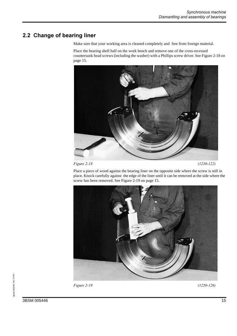
Make sure that your working area is cleaned completely and free from foreign material.
Place the bearing shell half on the work bench and remove one of the cross-recessed countersunk head screws (including the washer) with a Phillips screw driver. See Figure 2-18 on page 15.
Place a piece of wood against the bearing liner on the opposite side where the screw is still in place. Knock carefully against the edge of the liner until it can be removed at the side where the screw has been removed. See Figure 2-19 on page 15.
3BSM 005446 15

3BS
M 0
0544
6, R
ev.
B E
N -
The liner material is very soft. Be very careful, when installing the new liner, not to scratch or to damage the new liner.
Tap down the new liner with very little force by using a plastic hammer as shown in Figure 2-20 on page 16 until the liner projects approx. 5 mm above the horizontal joint of the bearing shell.
Place a drop of Loctite in the tapped hole. See Figure 2-21 on page 16.
Place the washer in the tapped hole and tighten the cross-recessed countersunk screw with a Phillips screw driver (Figure 2-22 on page 17). Tap down the liner very carefully by using a
3BSM 005446 16

3BS
M 0
0544
6, R
ev.
B E
N -
plastic hammer as shown in Figure 2-20 on page 16 until the liner is even with the horizontal joint.
After both halves have been fitted with new bearing liners, place both halves with the plane machined surfaces down onto the work bench. Insert the four M 24 hex. socket head cap bolts and tighten carefully each bolt a little at a time with a torque wrench until both halves are assembled with a torque of 735 Nm. Hold down the bearing shell assembly while tightening the bolts. See Figure 2-23 on page 17.
3BSM 005446 17

3BS
M 0
0544
6, R
ev.
B E
N -
Measure the inner bearing liner diameter at both ends of the liner in the bearing shell and at least two diametrically opposite places with an inside micrometer as shown in Figure 2-24 on page 18 and Figure 2-25 on page 18.
Write down the values measured and compare them with the shaft diameter values from the final test protocols.
A radial play between bearing liner diameter and rotor shaft diameter of a minimum of 0.34 mm and a maximum of 0.45 mm is acceptable.
Separate the bearing shell halves for assembly into the bearing housing.
3BSM 005446 18
3BS
M 0
0544
6, R
ev.
B E
N -
! !"#$ %!
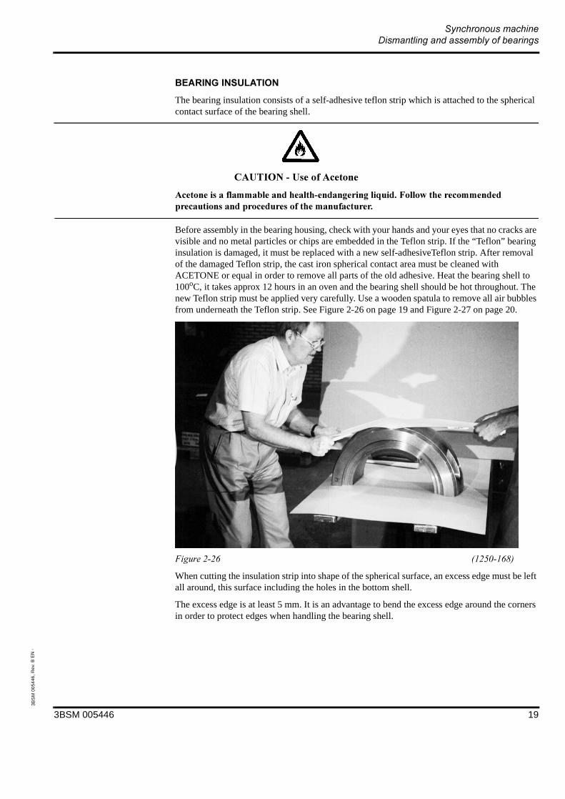
The bearing insulation consists of a self-adhesive teflon strip which is attached to the spherical contact surface of the bearing shell.
//(
( " 0 *,! (( ( (*
Before assembly in the bearing housing, check with your hands and your eyes that no cracks are visible and no metal particles or chips are embedded in the Teflon strip. If the “Teflon” bearing insulation is damaged, it must be replaced with a new self-adhesiveTeflon strip. After removal of the damaged Teflon strip, the cast iron spherical contact area must be cleaned with ACETONE or equal in order to remove all parts of the old adhesive. Heat the bearing shell to 100oC, it takes approx 12 hours in an oven and the bearing shell should be hot throughout. The new Teflon strip must be applied very carefully. Use a wooden spatula to remove all air bubbles from underneath the Teflon strip. See Figure 2-26 on page 19 and Figure 2-27 on page 20.
When cutting the insulation strip into shape of the spherical surface, an excess edge must be left all around, this surface including the holes in the bottom shell.
The excess edge is at least 5 mm. It is an advantage to bend the excess edge around the corners in order to protect edges when handling the bearing shell.
3BSM 005446 19
3BS
M 0
0544
6, R
ev.
B E
N -
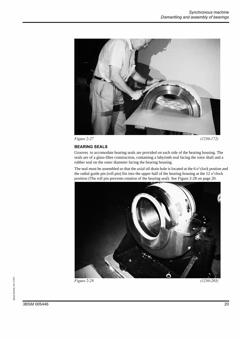
!#Grooves to accomodate bearing seals are provided on each side of the bearing housing. The seals are of a glass-fibre construction, containing a labyrinth seal facing the rotor shaft and a rubber seal on the outer diameter facing the bearing housing.
The seal must be assembled so that the axial oil drain hole is located at the 6 o’clock postion and the radial guide pin (roll pin) fits into the upper half of the bearing housing at the 12 o’clock position (The roll pin prevents rotation of the bearing seal). See Figure 2-28 on page 20.
3BSM 005446 20

3BS
M 0
0544
6, R
ev.
B E
N -
& The teflon lining of the bearing shell is very soft and can be damaged quite easily. Inspect both the upper and lower bearing shell very carefully for damage, metal chips, impurities and even air bubbles in the lining. The inspection is to be made by eye and by using your hand, feeling after damage.
# " " %"% ( " " )! ( ! ")"* ( %"( "( "*
( " "( *
Basically, reassembly is executed in the reverse order as described in Section 2.1.
The hydraulic jack is still underneath the rotor shaft as described in Section 2.1 Figure 2-14 on page 12.
Apply a thin coat of oil to components which are to be assembled.
3BSM 005446 21

3BS
M 0
0544
6, R
ev.
B E
N -
Insert five lifting eyes in the lower bearing shell and lift the shell over and onto the rotor shaft. Lower the bearing half on the shaft, remove the upper lifting eye, hold onto 2 of the lifting eyes as shown in Figure 2-29 on page 22 and allow the shell to glide around the journal until the lower shell is inserted. See Figure 2-30 on page 22 and Figure 2-31 on page 23.
3BSM 005446 22
3BS
M 0
0544
6, R
ev.
B E
N -
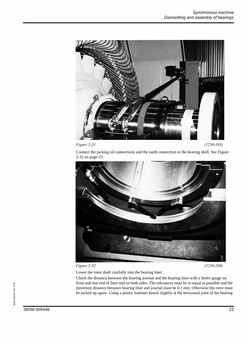
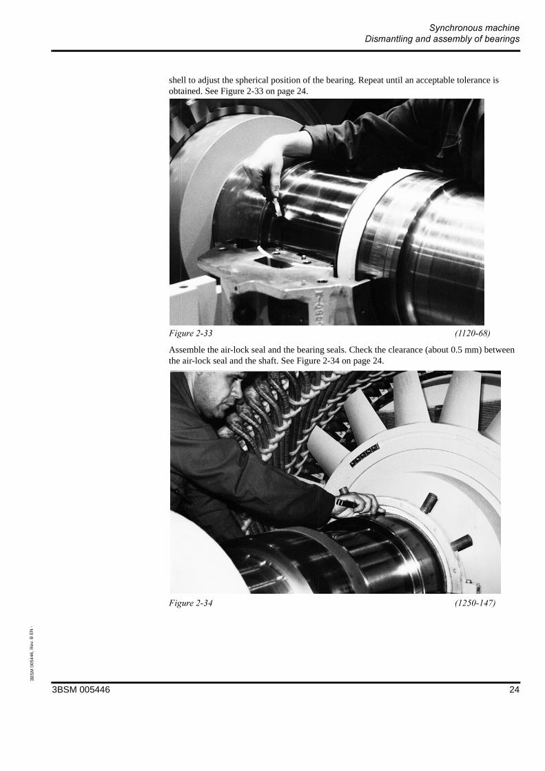
Connect the jacking oil connections and the earth connection to the bearing shell. See Figure 2-32 on page 23.
Lower the rotor shaft carefully into the bearing liner.
Check the distance between the bearing journal and the bearing liner with a feeler gauge on front and rear end of liner and on both sides. The tolerances must be as equal as possible and the minimum distance between bearing liner and journal must be 0.1 mm. Otherwise the rotor must be jacked up again. Using a plastic hammer knock slightly at the horizontal joint of the bearing
3BSM 005446 23
3BS
M 0
0544
6, R
ev.
B E
N -
shell to adjust the spherical position of the bearing. Repeat until an acceptable tolerance is obtained. See Figure 2-33 on page 24.
Assemble the air-lock seal and the bearing seals. Check the clearance (about 0.5 mm) between the air-lock seal and the shaft. See Figure 2-34 on page 24.
3BSM 005446 24

3BS
M 0
0544
6, R
ev.
B E
N -
Lift the upper bearing shell into position as shown in Figure 2-35 on page 25.
Insert the four M24 hex. head cap bolts and tighten the bolts with a torque wrench to 735 Nm. See Figure 2-36 on page 25. Be sure that the bolts for separating the shell are in the original position as before the dismantling.
3BSM 005446 25
3BS
M 0
0544
6, R
ev.
B E
N -
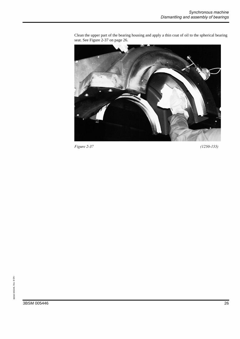
Clean the upper part of the bearing housing and apply a thin coat of oil to the spherical bearing seat. See Figure 2-37 on page 26.
3BSM 005446 26

3BS
M 0
0544
6, R
ev.
B E
N -
// (
,! (( ( (*
Clean the horizontal joint of the lower and upper bearing housing carefully and apply a thin coat of “Permatex Form a Gasket no. 2” sealing compound . See Figure 2-38 on page 27, Figure 2-39 on page 28 and Figure 2-40 on page 28.
3BSM 005446 27
3BS
M 0
0544
6, R
ev.
B E
N -
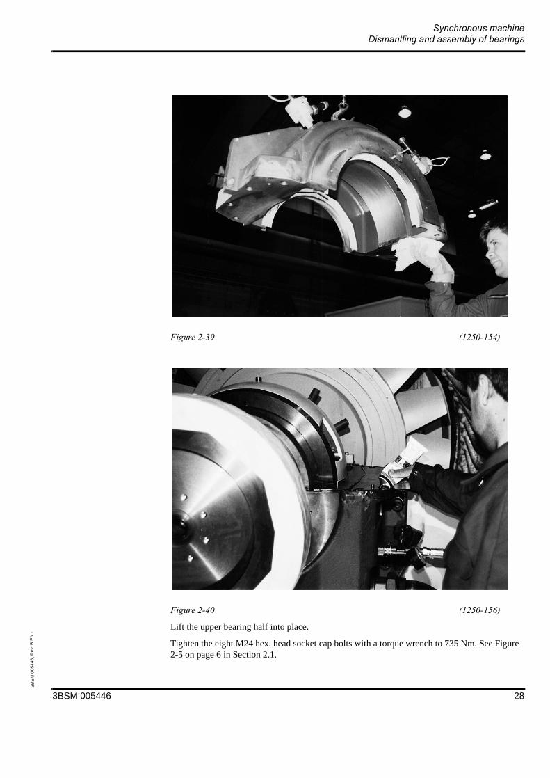
Lift the upper bearing half into place.
Tighten the eight M24 hex. head socket cap bolts with a torque wrench to 735 Nm. See Figure 2-5 on page 6 in Section 2.1.
3BSM 005446 28
3BS
M 0
0544
6, R
ev.
B E
N -
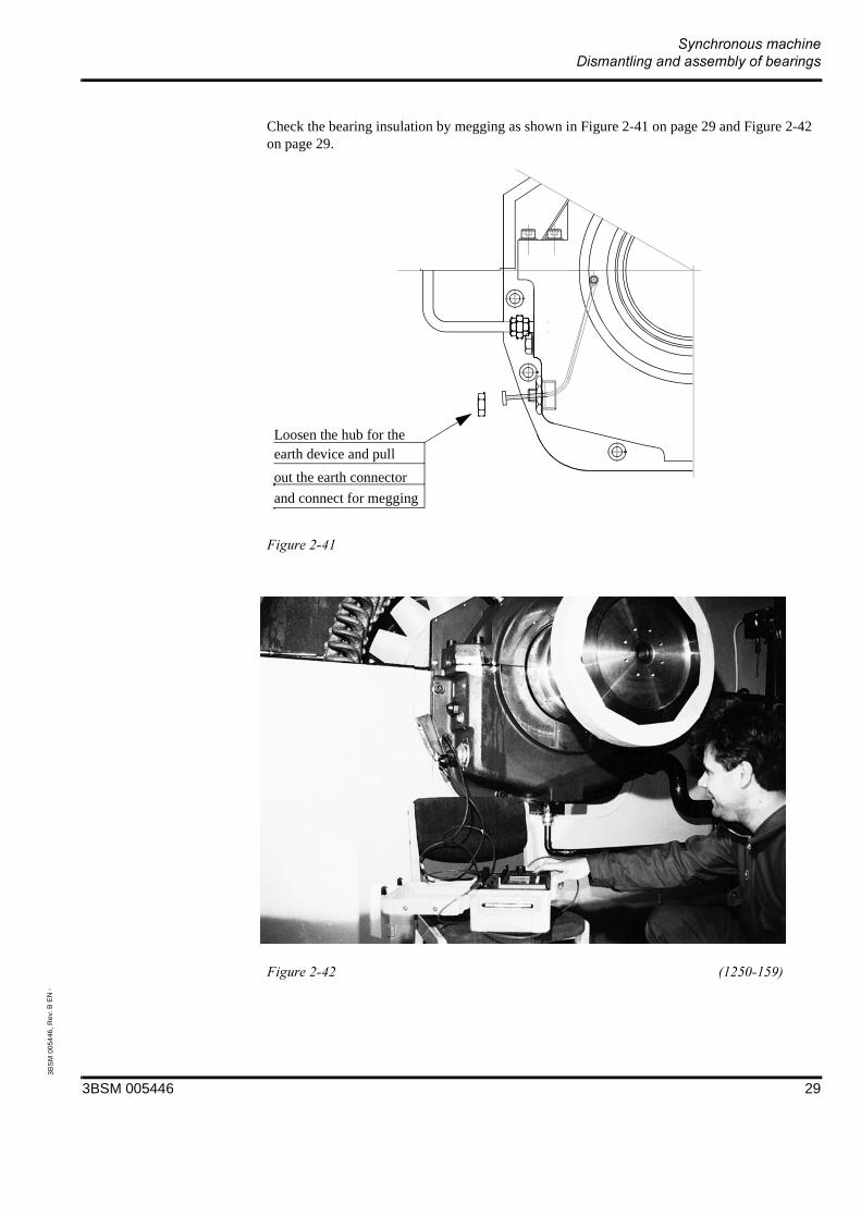
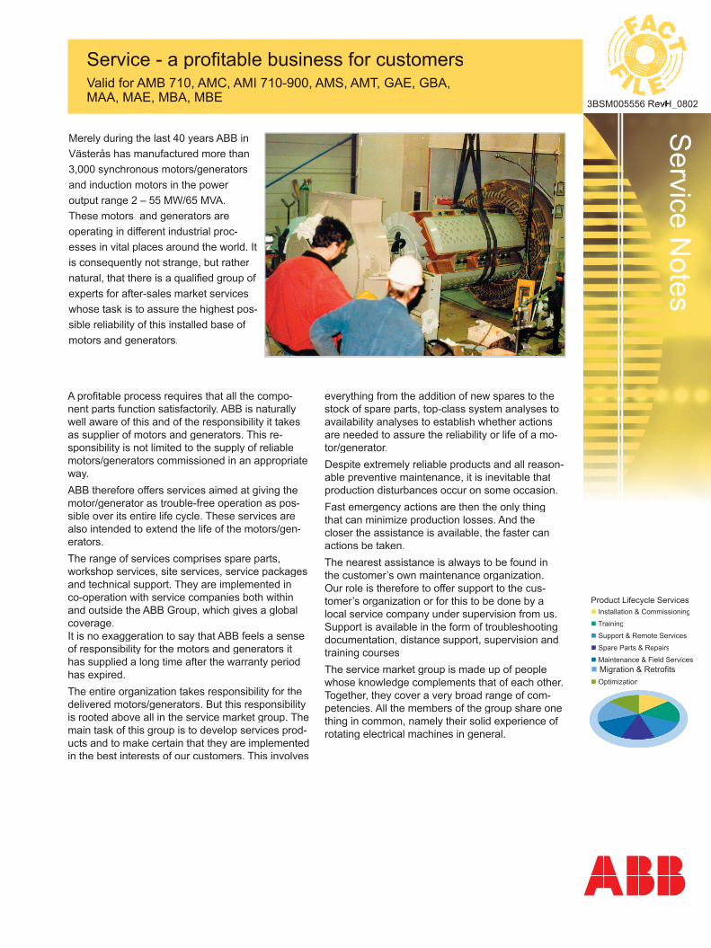
Check the bearing insulation by megging as shown in Figure 2-41 on page 29 and Figure 2-42 on page 29.
Loosen the hub for the
out the earth connector
and connect for megging
earth device and pull
3BSM 005446 29

3BS
M 0
0544
6, R
ev.
B E
N -
' (Recommended tightening torque for bolts property class 8.8, slightly coated with oil.
# '+" )1+(2*
) *+ *, *
$( (Nm)(lbft)
22.516.6
4533
7958
) *- *, *' *&,
$( (Nm)(lbft)
190140
420300
735550
15001100
3BSM 005446 30

3BSM 005446
2001-09-13
Service N
otes
Product Lifecycle Services Installation & Commissioning
Training
Support & Remote Services
Spare Parts & Repairs
Maintenance & Field Services Migration & Retrofi ts Optimization
Service - a profi table business for customersValid for AMB 710, AMC, AMI 710-900, AMS, AMT, GAE, GBA, MAA, MAE, MBA, MBE 3BSM005556 RevH_08023BSM005556 RevH_0802
Merely during the last 40 years ABB in Västerås has manufactured more than 3,000 synchronous motors/generators and induction motors in the power output range 2 – 55 MW/65 MVA.These motors and generators are operating in different industrial proc-esses in vital places around the world. It is consequently not strange, but rather natural, that there is a qualifi ed group of experts for after-sales market services whose task is to assure the highest pos-sible reliability of this installed base of motors and generators.
A profi table process requires that all the compo-nent parts function satisfactorily. ABB is naturally well aware of this and of the responsibility it takes as supplier of motors and generators. This re-sponsibility is not limited to the supply of reliable motors/generators commissioned in an appropriate way.ABB therefore offers services aimed at giving themotor/generator as trouble-free operation as pos-sible over its entire life cycle. These services are also intended to extend the life of the motors/gen-erators. The range of services comprises spare parts,workshop services, site services, service packages and technical support. They are implemented in co-operation with service companies both within and outside the ABB Group, which gives a global coverage.It is no exaggeration to say that ABB feels a sense of responsibility for the motors and generators it has supplied a long time after the warranty period has expired.The entire organization takes responsibility for the delivered motors/generators. But this responsibility is rooted above all in the service market group. The main task of this group is to develop services prod-ucts and to make certain that they are implemented in the best interests of our customers. This involves
everything from the addition of new spares to the stock of spare parts, top-class system analyses to availability analyses to establish whether actions are needed to assure the reliability or life of a mo-tor/generator.Despite extremely reliable products and all reason-able preventive maintenance, it is inevitable that production disturbances occur on some occasion.Fast emergency actions are then the only thing that can minimize production losses. And the closer the assistance is available, the faster can actions be taken.The nearest assistance is always to be found in the customer’s own maintenance organization. Our role is therefore to offer support to the cus-tomer’s organization or for this to be done by a local service company under supervision from us. Support is available in the form of troubleshooting documentation, distance support, supervision and training coursesThe service market group is made up of people whose knowledge complements that of each other. Together, they cover a very broad range of com-petencies. All the members of the group share one thing in common, namely their solid experience of rotating electrical machines in general.

Service N
otes
Spe
cifi c
atio
ns s
ubje
ct to
cha
nge
with
out n
otic
e.
3BSM005556 RevH_08023BSM005556 RevH_0802
Preventive maintenance preserves the plant’s production capacityThe goal of preventive maintenance is to change the maintenance work from being mainly emer-gency interventions, where each problem is addressed as it arises, to planned actions with focus on reliability and minimizing of production disturbances.The basis of preventive maintenance is the im-plementation of a maintenance programme with recommended intervals. When supplemented by maintenance based on condition monitoring, analy-ses and checking of the performance carried out by experienced personnel, any deterioration can be discovered in time and corrective actions taken.
Improved plants through value-raising measuresThe machines supplied by us are always matched with the drive application for which they are in-tended. They are also state-of-the-art machines at the time of their delivery. However, developments never stand still. We are constantly gaining new experience.Today’s products consequently have a better performance and better operating characteristics performance and better operating characteristics perthan the motors/generators supplied earlier. The upgrading/modernization of motors and genera-tors supplied earlier and in service in many cases can therefore be a very profi table way to increase value. This value lies in higher production, less maintenance, higher raliability and longer life.
Central supportWith an installed base throughout the world, it is impossible to maintain in-depth specialist com-petence close to each individual customer. The solution is therefore to provide strongly centralized support services. Support that enables local ABB staff in sales and service companies to act as if the centrally located specialists were on the spot.
Krister JohanssonManagerWorking since 1989 at ABB as prod. engineering, supply management and the last four years as responsible for sales & marketing of motors.
Phone +46 (0)21 329509, Email: [email protected]
Björn LindbergTechnical supportHas been with ABB since 1994 and rotatng machinery since 2002, the latest year with development.
Phone +46 (0)21 329667, Email: [email protected]
Tobias ÖsterholmTechnical supportWorking since 2002 at ABB with rotating electrical machines as development engineer and with technical support.
Phone +46 (0)21 329446, Email: [email protected]
Mikael LevinSales and Technical support, orderhandlingWorking since 1989 at ABB with electrical machines as mechanical designer and project manager.
Phone +46 (0)21 329579, Email: [email protected]
Åke LöfbergCommissioningWorking since 1990 at ABB with com-missioning of control systems and electrical machines.
Phone + 46 (0)70-3997937, Email: [email protected]
Mikael KarlssonCommissioningWorking with com-missioning of control systems and electri-cal machines.
Phone: +46 703 30 86 80E-mail: [email protected]
Marko PikkarainenCommissioningWorking with com-missioning of control systems and electri-cal machines.
Phone: +46 (0)73 044 05 03E-mail: [email protected]
Åsa ÖrnstedtOrderhandlingWorking in ABB since 1987 and within Machines form 2007.
Phone +46 (0)21 348912, Email: [email protected]
Yngve Anundssonspecialist Sales and Technical supportWorking since 1975 at ABB. Worked as head of the test room and project manager. Since 1998 with After Sales.
Phone +46 (0)21 329521, Email: [email protected]
Jonas BurströmSales and Technical supportWorking since 1988 at ABB. The last years with synchronous motors and generators as projectmanager and area sales manager
Phone +46 (0)21 329527, Email: [email protected]
Erik EnglundSales and Technical supportWorking since 2005 at ABB andwith rotating electri-cal machines since 2006.
Phone: +46 (0)21 325802Email: [email protected]
Stefan WilsonSales and technical supportWorking since 1970 with rotating electrical machines in production, sup-ply management,and after sales service.
Phone:+46(0)21329499Email:[email protected]
Jonas CarlssonOrderhandlingWorking in ABB since 2001 within Machines from 2005.
Phone + +46 (0)21 329456, Email: [email protected]
Kjell Gauffi nOrderhandlingWorking since 1964 with rotating electrical machines, with sales and production.
Phone +46 (0)21 329561, Email: [email protected]
Leila Yli-KerkoOrderhandlingWorking since 1975 with rotating electri-cal machines as ma-chine operator, qual-ity control inspector and mechanical designer.
Phone + 46 (0)21 329558, Email: [email protected]
Roger AnderssonOrderhandlingWorking since 1988 at ABB. The last years with electrical machines.
Phone + 46 (0)21 329425, Email: [email protected]
Type of motors and generators manufactured by the Machines factory in Västerås. These machines are of the following types:Synchronous machines; AMS, AMT, GAE, GBAInduction machines; AMB 710, AMC, MAA, MAE, MBA, MBE, AMI 710-900 MBA, MBE, AMI 710-900
ABB ABMachinesElmotorgatan 2, Building 394Tel: +46 21 32 90 00Fax: +46 21 32 90 10www.abb.com/motors&generatorse-mail: Spare parts: [email protected] support: [email protected]


Servic
e N
ote
s
Product Lifecycle Services Installation & Commissioning
Training
Support & Remote Services
Spare Parts & Repairs
Maintenance & Field Services
Migration & Retrofits
Optimization
Recommended spares and spares supportValid for AMB 710, AMC, AMI, AMS, GBA
3BSM005991 RevB_0510
Scope of spares adapted to desired reliability and calculated risks
Availability is a matter of top priority, which requires special efforts. However, sooner or later, what shouldn’t happen does happen. A stoppage due to the failure of some part.It is now that the right spare should be available. If this is not so, you must then have the right supplier, who is able to dispatch the right component, quickly and reliably.Recommended spares, sets of spares and spares support are concepts synonymous with a high reliability
SummaryRecommendations for suitable spares can be made on the basis of the knowledge of the supplied product/plant, experience of the ap-plication and the operating conditions. We have prepared for our motors and genera-tors with accessories a list of recommended spares classified for different stages in the lifetime of the motor/generator. The recom-mended sets of spares have been coupled to our recommended maintenance programmes. Furthermore, we have matched them with dif-ferent “safety levels”.
BenefitsThe recommended spares are based on operating experience gained from thou-sands of machines. The total investment in spares need not oc-cur at the same time as the investment in a new machine. It is often sufficient to cover the first 3 to 4 years in conjunction with a new investment. The long-term scope of spares is suitably determined after a few years of operating experience. With the classified recommended spares, each customer has the opportunity to choose the scope of spares matched with the reliability demanded by the application and the calculated risks that are reason-able to take.
•
•
•

Servic
e N
ote
s
Spe
cific
atio
ns s
ubje
ct to
cha
nge
with
out n
otic
e.
3BSM005991 RevB_0510
ABB Automation Technologies ABMachinesElmotorgatan 2, Building 394Tel: +46 21 32 90 00Fax: +46 21 32 90 10www.abb.com/motors&drivese-mail: [email protected]
Review of spare partsABB Machines after-sales group files all the documents for each supplied machine. Based on the motor’s or generator’s serial number, detailed information can be retrieved for use later on to review the spares. In these reviews recommendations are given not only for the replacement of parts but also changing over to more modern solutions.
Spares supportWith a well-planned stock of spares – a stock where the spares are based on spares recom-mendations where the spares are easy to find – the basis for a high availability has been set for the machines supplied by us. But despite this, it is inevitable that spares must be pro-cured. Spares utilized have to be replaced. It is not always possible to predict the need for spares and to stock them.
In these cases it is necessary to have a supplier having good spares logistics who is able to dispatch quickly the missing compo-nent. We have a well-planned spares support arranged in co-operation with ABB Logistic Center.
By means of well-developed logistics, individually adapted routines for spares of different types and co-operation with global courier services, we are able to provide suitable spares support. For certain spares, e.g., printed circuit boards, repairs and return to the stock are a cost-effective solution. We have the routines for this.With access to the drawings, also for older machines, we are able to manufacture spares or propose new, modern solutions.
•
•
•
Structure of recommended sets of spares
Spares for normally 3 years of operation or max. 20,000 equivalent hours of operation.The spares are selected on the basis of general experience. The aim is to cover the need for spares according to level 1 and 2 in the recommended maintenance programme.
Spares for normally 3 – 12 years of operation or max. 80,000 equivalent hours of operationSpares should be selected on the basis of the first years of operation. The aim is to cover the need for spares for preventive maintenance according to level 3 and 4 in the maintenance programme.
Nor
mal
spa
res
need
s
Consumables that are to be replaced at certain intervals and spares that are criti-cal to operation.
Maintenance consumables and Maintenance replacement
Spares/components to be replaces at the maintain intervals. The scope covers both planned and unplanned maintenance
Spar
es fo
r ext
ra re
liabi
lity Spares for further
increasing the avail-ability.
Spares which in afew cases maybe be justified when extra reliability is needed. The scope can vary within wide limits from rotor coils to a complete spare machine.
Operation consumables and Operation back-up
Operation back-up, extension
Capital spares


We reserve all rights in this document and in the information contained therein. Reproduction,use or disclosure to third parties without express authority is strictly forbidden.ABB Automation Technology Products; 2003
Type des. Part no.
Prep. MKU / Stefan Palmgren 2003-05-27 Doc. kind Installation Instruction No. of p.
Appr. / Palmgren Stefan J ApprovedResp. dept MKU
Title Grouting of machine foundation plates 7
Doc. no. Lang. Rev. ind. Page
ABB Automation Technology Products 3BSM007280 en D 1
FILE: 3BSM007280.doc; TEMPLATE: Techn_Doc_Stand_P.dot A; SKELETON: ; SAVEDATE: 2004-12-21 1:10:00 PM
1. PurposeThe purpose of this instruction is to define the grouting methods that we recommend as a supplier of electric machines.
There are other methods for grouting but the following methods have been found to work well in most cases.
2. General safety instructionsThe work described in this manual is only to be performed by trained and authorized personnel.
The manufacturer is not responsible for incorrect use, which affect the safety due to change, use of components from other supplier than ABB, neglect or misuse.
The actual design can differ from the illustrations in this instruction. Contact ABB at slightest uncertainty that can affect the safety.
Use of solvents when cleaning and use of lubricants and other chemicals can affect the health and/or the safety of the personnel. The recommended safety measures and procedures from the supplier shall be followed.
The user must see to that the machine is properly secured in all points when lifting and other work that may cause injuries.
3. ReferencesThis document refers to a number of order specific documents.
1. Outline drawingThe measurements of the electric machine are indicated on the outline drawing valid for the order.
2. Foundation detail drawingSee valid figure drawing for mounting of foundation details (stated on outline drawing) for measurements of foundation details.
Doc. no. Lang. Rev. ind. Page
ABB Automation Technology Products 3BSM007280 en D 2
4. Preparations before mounting and coarse alignmentBefore mounting of the machine is begun, check that the foundation corresponds with the valid foundation detail drawing.The rotor is not in the magnetic neutral position at delivery due to transport locking.
The theoretical measurement for the axial neutral position of the machine is indicated on the valid outline drawing (measurement L5 on the foundation detail drawing). See test protocol in the machine manual for the exact as built measurement and use this measurement for final fine alignment.
The foundation details are normally supplied with the contact surfaces untreated. If the surfaces are treated with paint or other rust prevention, these surfaces must be sand blasted clean before grouting is done.
5. Mounting and alignment
5.1 Separate grouting of sole plates
The sole plates should be aligned in accordance with the specified outline drawing and foundation detail drawing.
1. Check on the underside that the threaded holes in the sole plates for the electric machine mounting screws are covered with foam rubber strips and that the holes for taper pins are covered with tape. The threaded holes are covered with foam rubber strips so the list, when mounting the machine, can be compressed and create space for the top of screws under the sole plates. Every thread in the sole plate will then be used. The holes for taper pins are covered to avoid that these are filled with grouting mix.
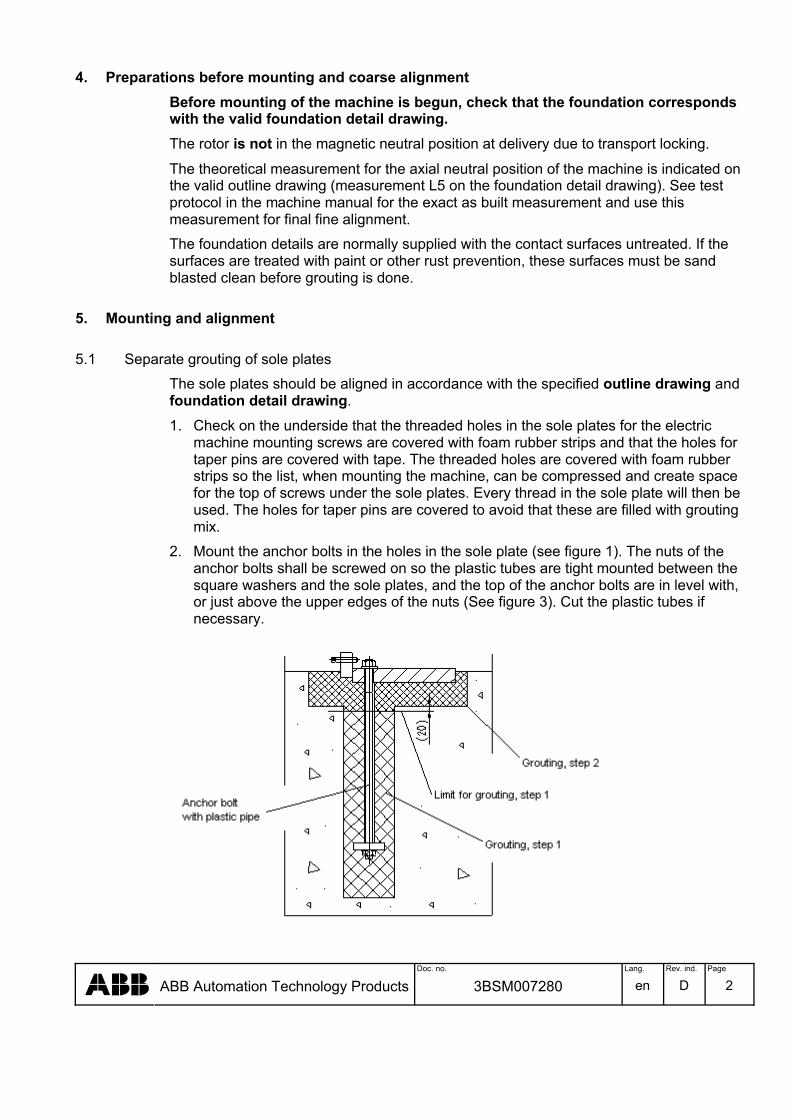
2. Mount the anchor bolts in the holes in the sole plate (see figure 1). The nuts of the anchor bolts shall be screwed on so the plastic tubes are tight mounted between the square washers and the sole plates, and the top of the anchor bolts are in level with, or just above the upper edges of the nuts (See figure 3). Cut the plastic tubes if necessary.
Doc. no. Lang. Rev. ind. Page
ABB Automation Technology Products 3BSM007280 en D 3
Figure 1
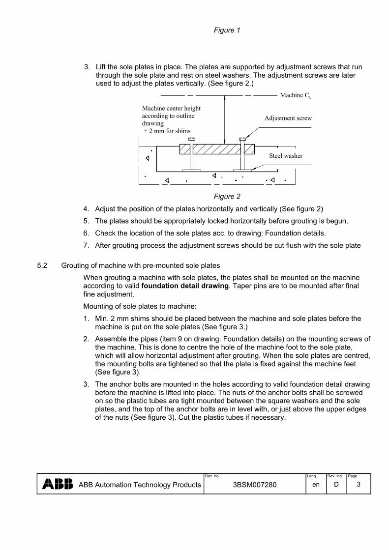
3. Lift the sole plates in place. The plates are supported by adjustment screws that run through the sole plate and rest on steel washers. The adjustment screws are later used to adjust the plates vertically. (See figure 2.)
Machine CL
Machine center heightaccording to outline drawing+ 2 mm for shims
Adjustment screw
Steel washer
Figure 2
4. Adjust the position of the plates horizontally and vertically (See figure 2)
5. The plates should be appropriately locked horizontally before grouting is begun.
6. Check the location of the sole plates acc. to drawing: Foundation details.
7. After grouting process the adjustment screws should be cut flush with the sole plate
5.2 Grouting of machine with pre-mounted sole plates
When grouting a machine with sole plates, the plates shall be mounted on the machine according to valid foundation detail drawing. Taper pins are to be mounted after final fine adjustment.
Mounting of sole plates to machine:
1. Min. 2 mm shims should be placed between the machine and sole plates before the machine is put on the sole plates (See figure 3.)
2. Assemble the pipes (item 9 on drawing: Foundation details) on the mounting screws of the machine. This is done to centre the hole of the machine foot to the sole plate, which will allow horizontal adjustment after grouting. When the sole plates are centred, the mounting bolts are tightened so that the plate is fixed against the machine feet (See figure 3).
3. The anchor bolts are mounted in the holes according to valid foundation detail drawing before the machine is lifted into place. The nuts of the anchor bolts shall be screwed on so the plastic tubes are tight mounted between the square washers and the sole plates, and the top of the anchor bolts are in level with, or just above the upper edges of the nuts (See figure 3). Cut the plastic tubes if necessary.

Doc. no. Lang. Rev. ind. Page
ABB Automation Technology Products 3BSM007280 en D 4
Figure 3
4. Mount the M16 adjustment screws from beneath the sole plate (see figure 3.1). Tighten the screws so they run free from the bottom of the recess in the foundation. If necessary cut the bolt flush with the topside of the sole plate. The adjustment screws are used to create extra support for the plate after grouting. They have no adjustment function.
Figure 3.1
WARNING – Heavy liftThe machine is a very heavy unit.
Use lifting equipment that is appropriate for the load, see valid outline drawing for weight.
5. Trestle the machine according to valid foundation detail drawing during grouting. Adjustment of height is done with appropriate shims. To raise the machine lifting jacks with low design (max 80 mm). The lifting jacks are placed between foundation and sole plate.
*)U sed when 4lif t ing jacks/side are needed
*)
Lift ing jacks
*)Suppor t blocks + Shims
A
A
Doc. no. Lang. Rev. ind. Page
ABB Automation Technology Products 3BSM007280 en D 5
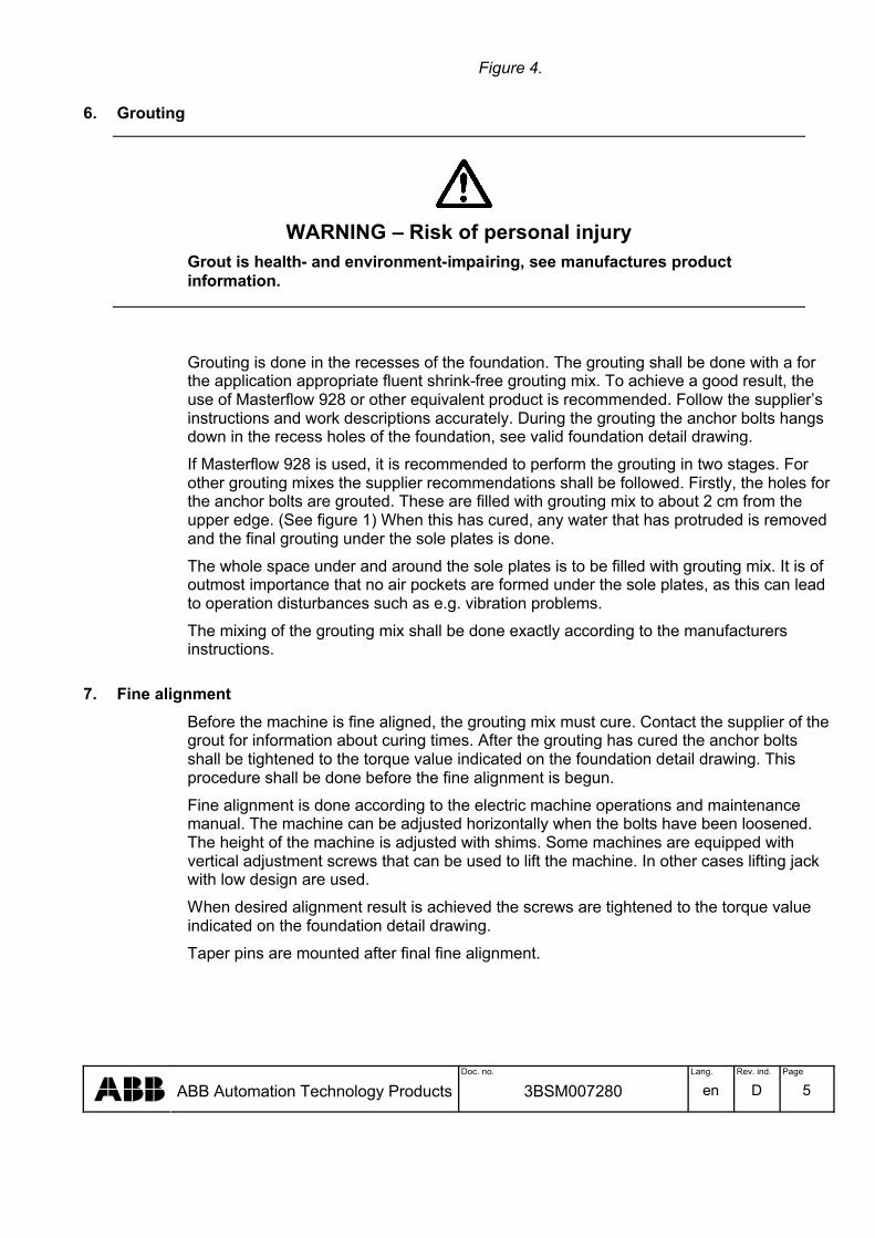
Figure 4.
6. Grouting
WARNING – Risk of personal injuryGrout is health- and environment-impairing, see manufactures product information.
Grouting is done in the recesses of the foundation. The grouting shall be done with a for the application appropriate fluent shrink-free grouting mix. To achieve a good result, the use of Masterflow 928 or other equivalent product is recommended. Follow the supplier’s instructions and work descriptions accurately. During the grouting the anchor bolts hangs down in the recess holes of the foundation, see valid foundation detail drawing.
If Masterflow 928 is used, it is recommended to perform the grouting in two stages. For other grouting mixes the supplier recommendations shall be followed. Firstly, the holes for the anchor bolts are grouted. These are filled with grouting mix to about 2 cm from the upper edge. (See figure 1) When this has cured, any water that has protruded is removed and the final grouting under the sole plates is done.
The whole space under and around the sole plates is to be filled with grouting mix. It is of outmost importance that no air pockets are formed under the sole plates, as this can lead to operation disturbances such as e.g. vibration problems.
The mixing of the grouting mix shall be done exactly according to the manufacturers instructions.
7. Fine alignmentBefore the machine is fine aligned, the grouting mix must cure. Contact the supplier of the grout for information about curing times. After the grouting has cured the anchor bolts shall be tightened to the torque value indicated on the foundation detail drawing. This procedure shall be done before the fine alignment is begun.
Fine alignment is done according to the electric machine operations and maintenance manual. The machine can be adjusted horizontally when the bolts have been loosened. The height of the machine is adjusted with shims. Some machines are equipped with vertical adjustment screws that can be used to lift the machine. In other cases lifting jack with low design are used.
When desired alignment result is achieved the screws are tightened to the torque value indicated on the foundation detail drawing.
Taper pins are mounted after final fine alignment.
Doc. no. Lang. Rev. ind. Page
ABB Automation Technology Products 3BSM007280 en D 6
8. Other
WARNING – Component damageTo avoid damages the following instructions must be carried out.
Check that air ducts and spaces in connection to the machine are free from loose concrete remnants and other pollution that can be drawn into the machine when started. Air ducts with concrete walls shall be painted for concrete to bond the concrete dust.
9. ResponsibilityThe purchaser is responsible that the foundation is dimensioned and designed correctly. Consideration shall be taken to, amongst others local conditions, occurring forces, passage for pipes and cables and also that service and maintenance can be performed.

Doc. no. Lang. Rev. ind. Page
ABB Automation Technology Products 3BSM007280 en D 7
REVISION
Rev. ind. Page (P) Chapt. (C)
Description Date Dept./Init.
A General Warning signs and text added MK/SPB Fig: 1 & 3 Anchoring bolts were counter sunk MKU/WMC General Sole plates where foundation plates, point 4 add in § 5.2 MK/SPD P 2-5 Chapter 4; 5.1.1; 5.1.2; 5.2; 5.2.3; 5.2.4; 7 MKU / HAAK

Service & Repair Synchronous machine Instruction for removal of rotor on site (GBA/AMS 1000, 1120, 1250, 1250A)
Document No.: 3BSM 009020
Contents1 - Safety1.1 General safety instructions ......................... 3
2 - Instruction for removal of rotor on site.2.1 Overhaul of machines according to Level 4
inspection in the manual............................. 42.2 Planned work.............................................. 52.3 Removal of main rotor ............................... 62.4 Assembly of main rotor............................ 132.5 Recommended tightening torque for bolts16

Synchronous machineRemoval removal
3BSM 009020 ii
3BS
M 0
0902
0, R
ev. B
EN
060
628
NOTICE
The information in this document is subject to change without notice and should not be construed as a commitment by ABB. ABB assumes no responsibility for any errors that may appear in this document.
In no event shall ABB be liable for direct, indirect, special, incidental or consequential damages of any kind arising from the use of this document, nor shall ABB be liable for incidential or consequential damages arising from the use of any software or hardware described in this document.
This document and parts thereof must not be reproduced or copied without ABB’s written permission, and the contents thereof must not be imparted to a third party nor be used for any unauthorized purpose.
©Copyright 2001 ABB. All rights reserved.
Synchronous machineSafety
3BSM 009020 3
3BS
M 0
0902
0, R
ev. B
EN
060
628
1 Safety
1.1 General safety instructionsThe procedures described in this manual are only to be performed by trained personnel authorized by the user.
The manufacturer is not responsible for malfunctions that comprise safety as a result of alteration, use of non ABB replacement parts, neglect or misuse.
Replacement parts may vary from those shown in this manual. Should you have questions on those parts please contact ABB Automation Technologies AB.
The actual appearance of the machine may vary from the illustration in this manual.
Should pre-owned ABB equipment be purchased and reconditioned, the equipment should not be used until testing and analysis demonstrate that the equipment meet the original or upgraded specifications.
The use of solvents as cleaning agents and the use of lubricants can involve health and/or safety hazards. The recommended precautions and procedures of the manufacturers should be followed.

Synchronous machineRotor removal
3BS
M 0
0902
0, R
ev. B
EN
060
628
2 Instruction for removal of rotor on site.
2.1 Overhaul of machines according to Level 4 inspection in the manual
Preparations
WARNING - Heavy lift
Make sure that all equipment is in good condition and appropriate for the load before starting the procedure.
Site PPE requirements.
• Hi Viz Jacket
• Safety Helmet
• Safety Glasses
• Safety Boots
3BSM 009020 4

Synchronous machineRotor removal
3BS
M 0
0902
0, R
ev. B
EN
060
628
2.2 Planned work
WARNING - High voltage
This work involves the main circuits of the generator normally connected to the high voltage supply net. Before you start to work:
1. Make sure the generator is disconnected from the high voltage net and that the circuit breaker is locked in the open position so it not accidentally (or otherwise) can be closed during the measurements.
2. Note also that capacitors can contain dangerous voltages, so be sure to ground all details before you touch them.
Remove the cooler top, covers, bearings, main rotor and perform level 4 inspection.
Dismantling, assembling and inspections including measurements in accordance with the order specific manual for the machine.
3BSM 009020 5

Synchronous machineRotor removal
3BS
M 0
0902
0, R
ev. B
EN
060
628
2.3 Removal of main rotor
WARNING - Risk of personal injury
When the rotor is moved out of the stator and is supported for fitting a new extension piece, make sure to place an external support under the exciter end. The centre of gravity is otherwise outside the support and the rotor will tip, possibly endangering personnel.
Figure 2-1
NOTE: It is strongly recommended that rotor removal and reassembly should be performed by professional service or commissioning engineers authorised by ABB.
1. Ensure that a valid work permit is applicable and all members of the working party are familiar with the work method statement, the specific maintenance procedures and test required.
2. Ensure before working on any electrical equipment, general electrical safety precautions are to be taken and local regulation are to be respected, according to instructions of the customer personal in charge of security, in order to prevent personnel accidents. See users manual, Chapter 7.
Sliding support plate
Sliding plate
Draw plate
3BSM 009020 6

Synchronous machineRotor removal
3BS
M 0
0902
0, R
ev. B
EN
060
628
3. Ensure before start of work that the machine is disconnected from the high voltage net and that the circuit breaker is locked in the open position so it not accidentally (or otherwise) can be closed during work and measurements. Ensure that the machine is grounded. See user manual, Chapter 5.
4. Before use inspect the installed lifting equipment and ensure that all lifting equipments have current test certificates.
5. Disconnect the machine shaft from all the driven objects. The rotor pole position should be 3, 6, 9 and 12 o’clock.
6. Remove the end plates on the cover and cooler top by the crane.
7. Remove the PMG stator and in accordance with the users manual.
8. Remove the exciter stator by the truck and in accordance with the users manual.
9. Remove the oil pipes, temperature probes etc from the bearing in accordance with the manual.
10. Assembly the draw plate to the shaft end on ND-end.
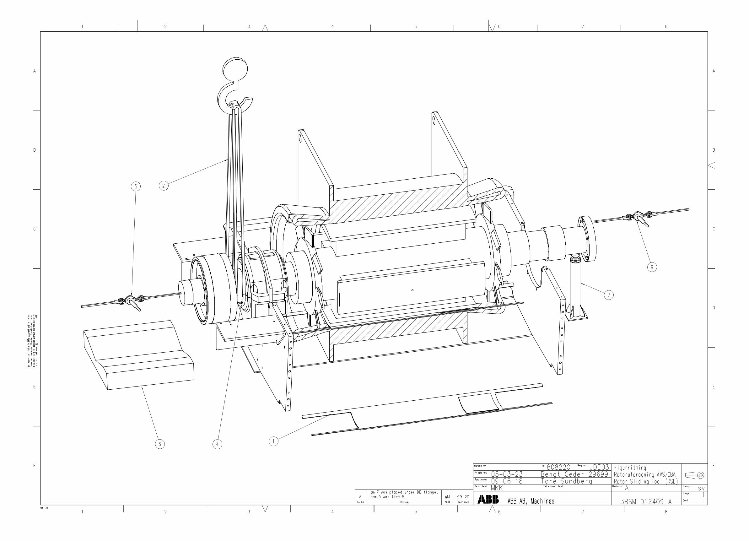
11. Apply the towing equipment on D-end and ND-end, use tackle blocks/chain hoists (optional equipment) and slings (optional equipment). See Figure 2-2 on page 7.D-end - shall be mounted somewhere on the gearbox/steam turbine, on a hook in the
wall or something else and around the shaft end, and shall be used as counterstay to prevent to much movement during the removal of the rotor.
ND-end - shall be mounted on a hook in the wall or somewhere else and to the draw plate mounted on the shaft, and shall be used to draw the rotor out of the stator.
Figure 2-2
Towing equipment
Towing equipment
Max 5kN
Max 5kN
3BSM 009020 7
Synchronous machineRotor removal
3BS
M 0
0902
0, R
ev. B
EN
060
628
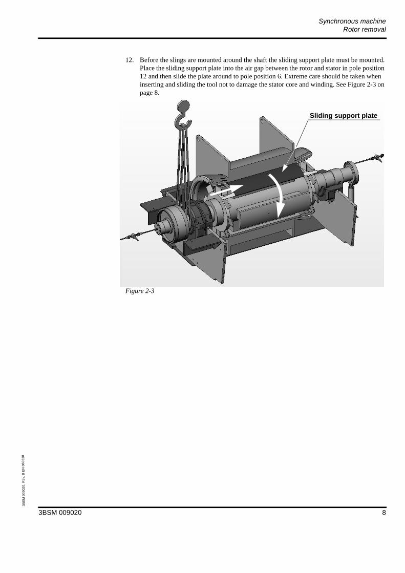
12. Before the slings are mounted around the shaft the sliding support plate must be mounted.Place the sliding support plate into the air gap between the rotor and stator in pole position 12 and then slide the plate around to pole position 6. Extreme care should be taken when inserting and sliding the tool not to damage the stator core and winding. See Figure 2-3 on page 8.
Figure 2-3
Sliding support plate
3BSM 009020 8
Synchronous machineRotor removal
3BS
M 0
0902
0, R
ev. B
EN
060
628
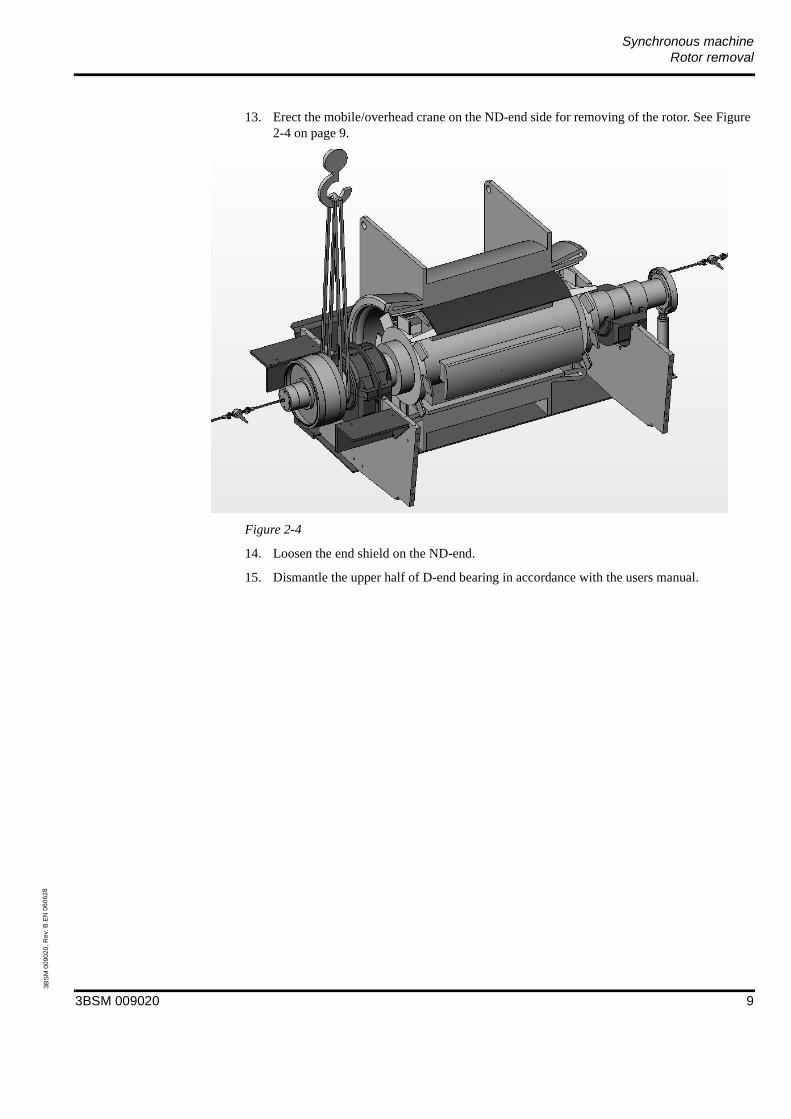
13. Erect the mobile/overhead crane on the ND-end side for removing of the rotor. See Figure 2-4 on page 9.
Figure 2-4
14. Loosen the end shield on the ND-end.
15. Dismantle the upper half of D-end bearing in accordance with the users manual.
3BSM 009020 9
Synchronous machineRotor removal
3BS
M 0
0902
0, R
ev. B
EN
060
628
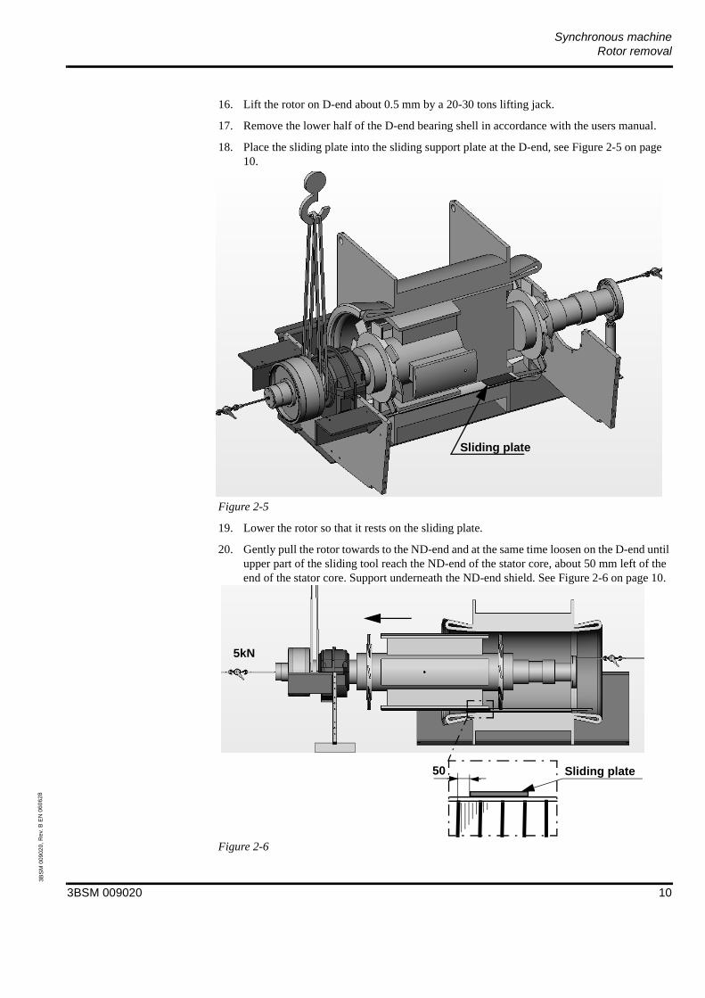
16. Lift the rotor on D-end about 0.5 mm by a 20-30 tons lifting jack.
17. Remove the lower half of the D-end bearing shell in accordance with the users manual.
18. Place the sliding plate into the sliding support plate at the D-end, see Figure 2-5 on page 10.
Figure 2-5
19. Lower the rotor so that it rests on the sliding plate.
20. Gently pull the rotor towards to the ND-end and at the same time loosen on the D-end until upper part of the sliding tool reach the ND-end of the stator core, about 50 mm left of the end of the stator core. Support underneath the ND-end shield. See Figure 2-6 on page 10.
Figure 2-6
Sliding plate
50
5kN
Sliding plate
3BSM 009020 10

Synchronous machineRotor removal
3BS
M 0
0902
0, R
ev. B
EN
060
628
21. Move the slings to be around the rotor body and lift with the mobile/overhead crane and move carefully towards the ND-end. Be sure that the rotor is in balance before moving so the rotor not will destroy the stator coil ends. Move until the rotor is free to be removed.
Figure 2-7
22. Support underneath the shaft on the D-end and underneath the pole on ND-end by hard wood and remove the support underneath the ND-end shield. See Figure 2-8 on page 11.
Figure 2-8
23. Remove the ND-end shield and bearing.
3BSM 009020 11

Synchronous machineRotor removal
3BS
M 0
0902
0, R
ev. B
EN
060
628
24. Lift the rotor and lay it down on the cradle. See Figure 2-9 on page 12.
Figure 2-9
25. Perform the inspection Level 4 in accordance with the users manual.
Store the rotor on solid supports and high enough so that the exciter not will be destroyed. Protect the rotor with a tapaulin.
Store both halves of the bearing shells in a very clean place. It is strictly forbidden to store metal chips and other metallic compontents together with the bearings.
Make sure that the bearing halves are stored together and that they cannot be mixed with other components when both bearings (D-end and ND-end) are store together. The bearing halves are marked with identity numbers to avoid incorrect assembly which could cause serious problems.
3BSM 009020 12
Synchronous machineRotor removal
3BS
M 0
0902
0, R
ev. B
EN
060
628
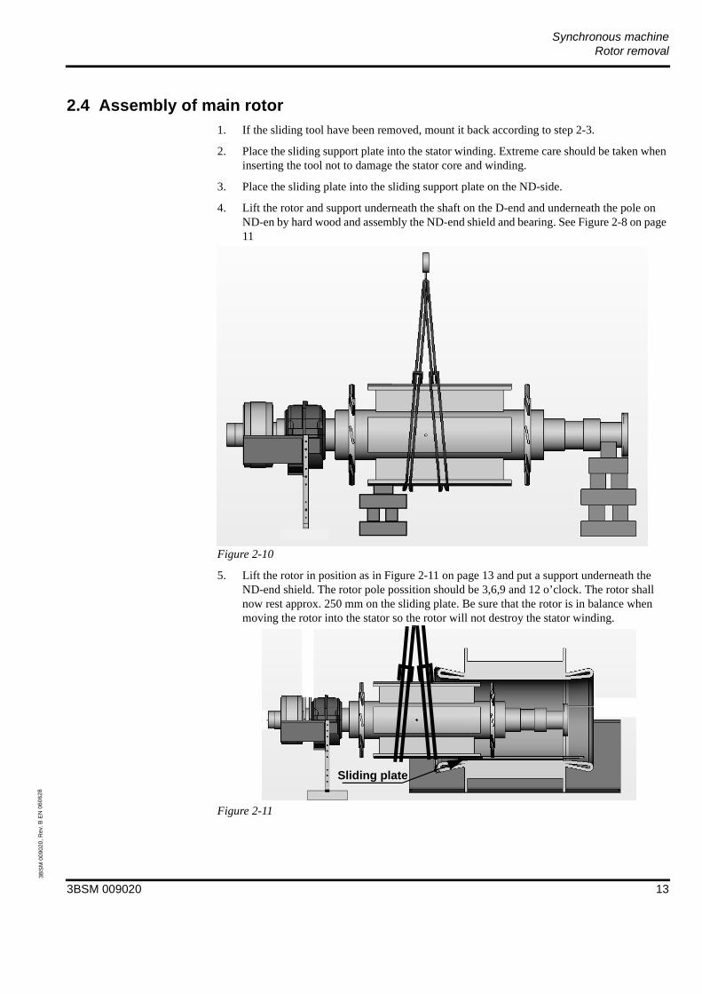
2.4 Assembly of main rotor1. If the sliding tool have been removed, mount it back according to step 2-3.
2. Place the sliding support plate into the stator winding. Extreme care should be taken when inserting the tool not to damage the stator core and winding.
3. Place the sliding plate into the sliding support plate on the ND-side.
4. Lift the rotor and support underneath the shaft on the D-end and underneath the pole on ND-en by hard wood and assembly the ND-end shield and bearing. See Figure 2-8 on page 11
Figure 2-10
5. Lift the rotor in position as in Figure 2-11 on page 13 and put a support underneath the ND-end shield. The rotor pole possition should be 3,6,9 and 12 o’clock. The rotor shall now rest approx. 250 mm on the sliding plate. Be sure that the rotor is in balance when moving the rotor into the stator so the rotor will not destroy the stator winding.
Figure 2-11
Sliding plate
3BSM 009020 13
Synchronous machineRotor removal
3BS
M 0
0902
0, R
ev. B
EN
060
628
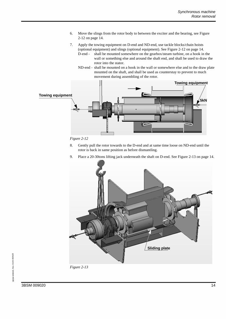
6. Move the slings from the rotor body to between the exciter and the bearing, see Figure 2-12 on page 14.
7. Apply the towing equipment on D-end and ND-end, use tackle blocks/chain hoists (optional equipment) and slings (optional equipment). See Figure 2-12 on page 14.D-end - shall be mounted somewhere on the gearbox/steam turbine, on a hook in the
wall or something else and around the shaft end, and shall be used to draw the rotor into the stator.
ND-end - shall be mounted on a hook in the wall or somewhere else and to the draw plate mounted on the shaft, and shall be used as counterstay to prevent to much movement during assembling of the rotor.
Figure 2-12
8. Gently pull the rotor towards to the D-end and at same time loose on ND-end until the rotor is back in same position as before dismantling.
9. Place a 20-30tons lifting jack underneath the shaft on D-end. See Figure 2-13 on page 14.
Figure 2-13
Towing equipment
Towing equipment
5kN
Sliding plate
3BSM 009020 14
Synchronous machineRotor removal
3BS
M 0
0902
0, R
ev. B
EN
060
628
10. Lift the rotor, on D-end, about 0.5mm with the lifting jack.
11. Reassembly the end shield on the D-end.
12. Assembly the lower half of the D-end bearing and end shield in accordance with the users manual.
13. Remove the towing equipments.
14. Remove the sliding plate from the sliding support plate.
15. Lower the rotor down into the D-end bearing wiht the lifting jack.
16. Remove the lifting jack from the D-end.
17. Remove the lifting slings.
18. Remove the sliding support plate by sliding the plate from position 6 to position 12 and remove the plate carefully from the air gap. Be careful not destroy the stator winding and stator coil ends.
19. Reassembly the upperhalf of the D-end bearing accordance with the users manual.
20. Reassembly the oil pipes, temperature probes, etc to the bearing in accordings with the manual.
21. Reassembly the exciter stator and in accordance with the users manual.
22. (If PMG) Reassembly the PMG stator in accordance with the users manual.
23. Reassembly the end plates on the cover.
24. Reassembly the cooler top.
25. Connect the machine shaft to the driven/driving object.
26. Clean and clear site working area of all tools and equipment.
3BSM 009020 15

Synchronous machineRotor removal
3BS
M 0
0902
0, R
ev. B
EN
060
628
2.5 Recommended tightening torque for boltsRecommended tightening torque for bolts property class 8.8, slightly coated with oil.
NOTE: Do not use Molybdenum di-sulphide, “Molycote”.
Bolt size M 8 M 10 M 12
Torque (Nm)(lbft)
22.516.6
4533
7958
Bolt size M 16 M 20 M 24 M 30
Torque (Nm)(lbft)
190140
420300
735550
15001100
3BSM 009020 16

3BSM 0090202006-06-28

Service & Repair Synchronous machine Replacement of diodes and thyristors
Document No.: 3BSM901869
Contents1 - Safety1.1 General safety instructions ............................................ 3
Chapter 2 - Replacement of diodes and thyristors
2.1 Change of diode ............................................................. 42.2 Change of control pulse unit.........................................112.3 Recommended tightening torque for bolts on the
machine........................................................................ 12

Synchronous machine
3BSM901869 ii
3BS
M90
1869
, Rev
. - E
N -
NOTICE
The information in this document is subject to change without notice and should not be construed as a commitment by ABB. ABB assumes no responsibility for any errors that may appear in this document.
In no event shall ABB be liable for direct, indirect, special, incidental or consequential damages of any kind arising from the use of this document, nor shall ABB be liable for incidential or consequential damages arising from the use of any software or hardware described in this document.
This document and parts thereof must not be reproduced or copied without ABB’s written permission, and the contents thereof must not be imparted to a third party nor be used for any unauthorized purpose.
©Copyright 2001 ABB. All rights reserved.

Synchronous machineSafety
3BSM901869 3
3BS
M90
1869
, Rev
. - E
N -
1 Safety
1.1 General safety instructionsThe procedures described in this manual are only to be performed by trained personnel authorized by the user.
The manufacturer is not responsible for malfunctions that comprise safety as a result of alteration, use of non ABB replacement parts, neglect or misuse.
Replacement parts may vary from those shown in this manual. Should you have questions on those parts please contact ABB Automation Technologies AB.
The actual appearance of the machine may vary from the illustration in this manual.
Should pre-owned ABB equipment be purchased and reconditioned, the equipment should not be used until testing and analysis demonstrate that the equipment meet the original or upgraded specifications.
The use of solvents as cleaning agents and the use of lubricants can involve health and/or safety hazards. The recommended precautions and procedures of the manufacturers should be followed.

Synchronous machineReplacement of diodes and thyristors
3BSM901869 4
3BS
M90
1869
, Rev
. - E
N -
Chapter 2 Replacement of diodes and thyristors
WARNING - Diode fault
If a faulty diode or thyristor the recommendation is to replace all diodes, thyristors and control pulse unit.
Warning - Magnetic force
There are very strong magnetic forces between the PMG rotor and stator.
1. Be extremely careful when removing the PMG stator frame. There are very strong magnetism to avoid, and prevent damage to components due to magnetic forces.
2. Remove your own wrist watch, credit cards and digital equipment before working around those strong magnetic forces.
3. Personnel with pace maker should not be working in the vecinity of the PMG.
2.1 Change of diodeIn order to loosen the assembly bracket, remove the two plastic plugs (one on each screw).
Open the spring lock as shown in Figure on page 5 and Figure on page 5 at the assembly bracket by using a screw driver and a mirror.
Figure 2-1 (1250-11)

Synchronous machineReplacement of diodes and thyristors
3BSM901869 5
3BS
M90
1869
, Rev
. - E
N -
Figure 2-2 (1250-12)
Loosen the hex. head socket cap bolts while pushing out the spring lock and lower the bracket so much that the diode can be removed. See Figure 2-3 on page 5.
Figure 2-3 (1250-13)
Observe and write down the direction of the black arrow on the front of the diode. The replacement diode must point in the same direction during the assembly proceedure.

Synchronous machineReplacement of diodes and thyristors
3BSM901869 6
3BS
M90
1869
, Rev
. - E
N -
The guide pin (roll pins) on each side of the diode are loose items. Make sure to place them in a safe place to avoid loss. See Figure 2-4 on page 6
Figure 2-4 (1250-14)
Clean the contact surface between the diode and the assembly bracket and the contact surface between the diode and the heat sink with piece of cloth damped in ACETONE. See Figure 2-5 on page 6.
Figure 2-5 (1250-15)

Synchronous machineReplacement of diodes and thyristors
3BSM901869 7
3BS
M90
1869
, Rev
. - E
N -
Clean the contact surfaces of the new diode by using steel wool and a cloth damped with ACETONE. See Figure 2-6 on page 7 and Figure 2-7 on page 7.
Figure 2-6 (1250-16)
Figure 2-7 (1250-17)

Synchronous machineReplacement of diodes and thyristors
3BSM901869 8
3BS
M90
1869
, Rev
. - E
N -
Apply a thin coat of Silicon grease (ABB part number 1269 0011-105) to both sides (contact areas) of the diode. See Figure 2-8 on page 8.
Figure 2-8 (1250-18)
Place the diode back between the heat sink and the mounting bracket.
NOTE: Rotate the diode so that the arrow marking of the diode is visible at the front. Check that the black arrow on the diode points in the same direction as the one that was removed earlier. See Figure 2-9 on page 8.
Figure 2-9 (1250-19)
Synchronous machineReplacement of diodes and thyristors
3BSM901869 9
3BS
M90
1869
, Rev
. - E
N -
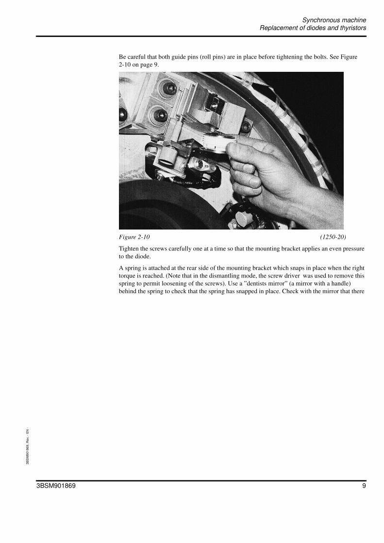
Be careful that both guide pins (roll pins) are in place before tightening the bolts. See Figure 2-10 on page 9.
Figure 2-10 (1250-20)
Tighten the screws carefully one at a time so that the mounting bracket applies an even pressure to the diode.
A spring is attached at the rear side of the mounting bracket which snaps in place when the right torque is reached. (Note that in the dismantling mode, the screw driver was used to remove this spring to permit loosening of the screws). Use a ”dentists mirror” (a mirror with a handle) behind the spring to check that the spring has snapped in place. Check with the mirror that there

Synchronous machineReplacement of diodes and thyristors
3BSM901869 10
3BS
M90
1869
, Rev
. - E
N -
is no visible gap between the spring and the mounting bracket body. The spring must be in place before the assembly is completed. See Figure 2-11 on page 10.
Figure 2-11 (1250-21)
Replace the plastic plugs.

Synchronous machineReplacement of diodes and thyristors
3BSM901869 11
3BS
M90
1869
, Rev
. - E
N -
2.2 Change of control pulse unitDisconnect the thyristor cables from the control pulse unit.
Loosen the two bolts which hold the control pulse unit to the holder, see Figure 2-12 on page 11.
Figure 2-12
Observe the connection of the control pulse unit, the new control pulse unit should have same connection.
For reassembly, mount the components in the reverse order.
Loosen the two bolts

Synchronous machineReplacement of diodes and thyristors
3BSM901869 12
3BS
M90
1869
, Rev
. - E
N -
2.3 Recommended tightening torque for bolts on the machineRecommended tightening torque for bolts, property class 8.8, slightly coated with oil.
OBS: Do not use Molybdenum di-sulphide, “Molycote”.
Bolt size M 8 M 10 M 12
Torque (Nm)(lbft)
22.516.6
4533
7958
Bolt size M 16 M 20 M 24 M 30
Torque (Nm)(lbft)
190140
420300
735550
15001100

3BSM9018692009-03-18

Installation and maintenance
Synchronous generator, type AMS 1250LD
Project: TABACALProject no.: L 000979

Skel
eton
No.
3B
SM00
5467
, EN
, Rev
. E
NOTICE
The information in this document is subject to change without notice and should not be construed as a commitment by ABB AB, Machines. ABB AB, Machines assumes no responsibility for any errors that may appear in this document.
In no event shall ABB be liable for direct, indirect, special, incidental or consequential damages of any kind arising from the use of this document, nor shall ABB be liable for incidential or consequential damages arising from the use of any software or hardware described in this document.
This document and parts thereof must not be reproduced or copied without ABB AB, Machines’s written permission, and the contents thereof must not be imparted to a third party nor be used for any unauthorized purpose.
©Copyright 2001 ABB. All rights reserved.
Synchronous generator, type AMSTable of Contents
XYK 210 090- FLD i
Skel
eton
No.
3B
SM00
5469
, Rev
. - E
N -
Chapter 1 - Introduction1.1 General information.................................................................................................... 71.2 Safety .......................................................................................................................... 71.3 Site conditions............................................................................................................. 71.4 Prerequisites................................................................................................................ 81.5 Contraindications ........................................................................................................ 81.6 Manual system and related documents ....................................................................... 9
Chapter 2 - Transport, Storage and Preparation for erection2.1 Transport and unpacking .......................................................................................... 10
2.1.1 Protective measures prior to transport ..................................................... 102.1.2 Check upon arrival................................................................................... 102.1.3 Transport anchor points ........................................................................... 112.1.4 Transport anchor points ........................................................................... 122.1.5 Lifting of crated equipment ..................................................................... 132.1.6 Unpacking................................................................................................ 132.1.7 Lifting of equipment ................................................................................ 14
2.2 Storage (this generator is prepared for long term storage) ....................................... 162.2.1 Short term storage of crated generator..................................................... 162.2.2 Long term storage of crated generator ..................................................... 162.2.3 Short term storage of uncrated generator................................................. 172.2.4 Long term storage of uncrated generator ................................................. 18
2.3 Preparation for erection ............................................................................................ 182.3.1 Check of foundation................................................................................. 182.3.2 Vertical and horizontal positioning.......................................................... 192.3.3 Removal of the transport locking device ................................................. 21
Chapter 3 - Alignment3.1 Preparations for generator installation...................................................................... 223.2 Rough levelling of generator after erection .............................................................. 23
3.2.1 Rough alignment...................................................................................... 233.3 Grouting .................................................................................................................... 243.4 Correction for thermal expansion ............................................................................. 253.5 Final alignment and inspection ................................................................................. 25
Chapter 4 - Mechanical and electrical installation4.1 Mechanical installation ............................................................................................. 26
4.1.1 Cooling arrangement................................................................................ 264.1.2 Connection of oil pipes ........................................................................... 264.1.3 Mounting of main terminal box ............................................................... 27
Synchronous generator, type AMSTable of Contents
XYK 210 090- FLD ii
Skel
eton
No.
3B
SM00
5469
, Rev
. - E
N -
4.2 Electrical installation ................................................................................................ 284.2.1 Connection of control equipment ............................................................ 284.2.2 Connection of high voltage cables........................................................... 284.2.3 Earth connection ...................................................................................... 28
Chapter 5 - Commissioning5.1 Check of mechanical installation.............................................................................. 295.2 Check of electrical installation ................................................................................. 305.3 Electrical checks ....................................................................................................... 315.4 Before the first start attempt ..................................................................................... 365.5 The first start attempts .............................................................................................. 36
5.5.1 Start interlocking...................................................................................... 365.6 Checks during running of the generator ................................................................... 36
5.6.1 Normal vibration levels ........................................................................... 375.6.1.1 Bearing housings ...............................................................375.6.1.2 Structural vibrations ..........................................................375.6.1.3 Shaft vibrations .................................................................38
5.6.2 Temperature levels................................................................................... 385.7 Check list .................................................................................................................. 38
5.7.1 Page 1....................................................................................................... 395.7.2 Page 2....................................................................................................... 405.7.3 Page 3....................................................................................................... 41
Chapter 6 - Operation6.1 Start up procedure..................................................................................................... 426.2 Continuous supervision............................................................................................. 426.3 Shut down procedures............................................................................................... 436.4 Alarm during operation............................................................................................. 43
Chapter 7 - Maintenance7.1 Preventive maintenance ............................................................................................ 467.2 Before all maintenance work .................................................................................... 467.3 Recommended maintenance program....................................................................... 47
7.3.1 Generator ................................................................................................. 487.3.2 Stator........................................................................................................ 497.3.3 Stator terminal.......................................................................................... 507.3.4 Rotor ........................................................................................................ 517.3.5 Bearings ................................................................................................... 537.3.6 PMG (Permanent magnetic generator) .................................................... 557.3.7 Exciter and Rectifier ............................................................................... 57
Synchronous generator, type AMSTable of Contents
XYK 210 090- FLD iii
Skel
eton
No.
3B
SM00
5469
, Rev
. - E
N -
7.3.8 Rotor earth brush ..................................................................................... 587.3.9 Cooling system ........................................................................................ 59
7.4 Main rotor coil turn insulation (voltage drop test).................................................... 607.5 Fault finding.............................................................................................................. 60
7.5.1 Diode fault ............................................................................................... 617.5.2 Altering the firing voltage........................................................................ 637.5.3 Lubrication............................................................................................... 647.5.4 High temperature in bearing .................................................................... 66
7.5.4.1 Trouble shooting 1 ............................................................667.5.4.2 Trouble shooting 2 ............................................................677.5.4.3 Trouble shooting 3 ............................................................68
7.5.5 High winding and/or air temperature....................................................... 697.5.5.1 Trouble shooting ...............................................................69
Chapter 8 - Disposal and Recycling8.1 General...................................................................................................................... 708.2 Dismantling the machine .......................................................................................... 708.3 Separation of different types of material .................................................................. 70
8.3.1 Normal carbon steel ................................................................................. 708.3.2 Electrical silicon steel non oriented ......................................................... 718.3.3 Special high quality steel ......................................................................... 718.3.4 Mixed metallic material ........................................................................... 718.3.5 Stainless steel ........................................................................................... 718.3.6 Cast iron................................................................................................... 718.3.7 Aluminium............................................................................................... 718.3.8 Copper...................................................................................................... 72
8.4 Waste as land fill....................................................................................................... 738.5 Hazardous waste ....................................................................................................... 738.6 Final comments......................................................................................................... 73
Synchronous generator, type AMSChapter 1 Introduction
XYK 210 090- FLD 1-7
Skel
eton
No.
3B
SM00
5470
, EN
, Rev
. E
Chapter 1 Introduction
1.1 General information• This installation and maintenance manual for the generator is a part of the main
documentation for this project. (refer to Section 1.6 ).
• This document is a manual for the generator with serial number 8267 088 and manufacturers order number L 000979.
• Actions described in this manual are only to be performed by trained personnel with previous experience in similar tasks, and authorized by the user.
1.2 SafetyThe machine is manufactured and intended for use only as described by this manual. Modification, alteration, or lack of maintenance as described in the manual, may adversely affect the safety and efficacy of this machine. The manufacturer is not responsible for malfunctions that comprise machinesafety as a result of alteration, use of non ABB replacements parts, neglect or misuse.
Replacements parts may vary from those shown in this manual. Should you have questions on those parts please contact ABB AB, Machines.
The actual apperarance of the machine may vary from the illustration in this manual.
Should pre-owned ABB equipment be purchased and reconditioned, the equipment should not be used until testing and analysis demonstrate that the equipment meets the original or upgraded specifications.
The use of solvents as cleaning agents and the use of lubricants can involve health and/or safety hazards. The recommended precautions and procedures of the manufacturer should be followed.
1.3 Site conditionsThis generator is to be used on a site with conditions according to ABB AB, Machines´s Technical Specification (included in binder “Users Manual”), clause D “Site conditions” and nowhere else.

Synchronous generator, type AMSChapter 1 Introduction
XYK 210 090- FLD 1-8
Skel
eton
No.
3B
SM00
5470
, EN
, Rev
. E
1.4 PrerequisitesThe operator must:
• be proficient in the application of the machine and electricity.
• be thoroughly trained in the skills and have the knowledge required to operate this machine.
• be thoroughly familiar with the contents of this manual and other operator´s manuals that deals with the machine and accessory devices that may be used with this machine.
• be fully qualified and trained in the operation of this machine and able to distinguish normal from aberrant device behaviour.
• never reset an alarm or trip until the reason for the alarm/trip has been located and necessary remedy has been made to make a safe restart of the machine.
1.5 ContraindicationsThe machine is not designed, sold or intended for any use except as indicated above. Furthermore, it is not intended to be used outside of the machine specifications or limitations. The machine must be in good working order.

Synchronous generator, type AMSChapter 1 Introduction
XYK 210 090- FLD 1-9
Skel
eton
No.
3B
SM00
5470
, EN
, Rev
. E
1.6 Manual system and related documents
Project: TABACAL
Project number: L 000979
Serial number 8267 088
Users Manualfor the generator
Technical Specification
Drawings for the generator
Machine part list
Installation & Maintenance manual
General ABB AB, Machines AMS Synchronous generator
Main terminal box
ABB AB, Machines Scope of Supply
Circuit Diagrams
Accessories & InstructionsTest Reports

Synchronous generator, type AMSChapter 2 Transport, Storage and Preparation for erection
XYK 210 090- FLD 2-10
Skel
eton
No.
3B
SM00
5471
, EN
, Rev
. G
Chapter 2 Transport, Storage and Preparation for erection
2.1 Transport and unpacking
2.1.1 Protective measures prior to transport• Irrespective of the method of transport or the distance, all generators are provided with an
axial movement locking device on the drive end bearing, to protect the bearings against damage during transport.
• Machined metal surfaces, such as the shaft extension, are provided with an anti-corrosive coating before delivery.
• The bearings are flooded with oil during the tests prior to delivery. This gives sufficient protection against corrosion for even the longest transport distances.
• The cooler should drain (blow) off water.
• For shipping overseas a generator of this size is packed in a strong wooden crate and should be located under deck. The wooden crate is provided with metal plates for protection and indications showing where the lifting wires are to be applied.
2.1.2 Check upon arrivalWhen the transport company delivers a generator to the customer, the responsibility for the handling passes to the customer or other party. Any transport damage must be reported within less than one 1 week after arrival if the transport insurance is to be claimed. It is therefore important that evidence of careless handling are to be checked and reported immediately to the transport company and the supplier.
A generator which is not to be installed immediately upon arrival must not be left without neither supervision nor without protective precautions. If the storage period is to be 9 months or more special precautions must be taken.
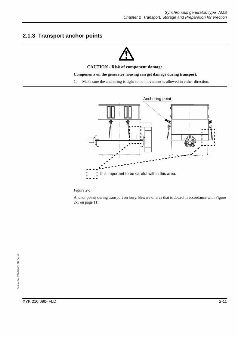
Synchronous generator, type AMSChapter 2 Transport, Storage and Preparation for erection
XYK 210 090- FLD 2-11
Skel
eton
No.
3B
SM00
5471
, EN
, Rev
. G
2.1.3 Transport anchor points
CAUTION - Risk of component damage
Components on the generator housing can get damage during transport.
1. Make sure the anchoring is tight so no movement is allowed in either direction.
Figure 2-1
Anchor points during transport on lorry. Beware of area that is dotted in accordance with Figure 2-1 on page 11.
It is important to be careful within this area.
Anchoring point
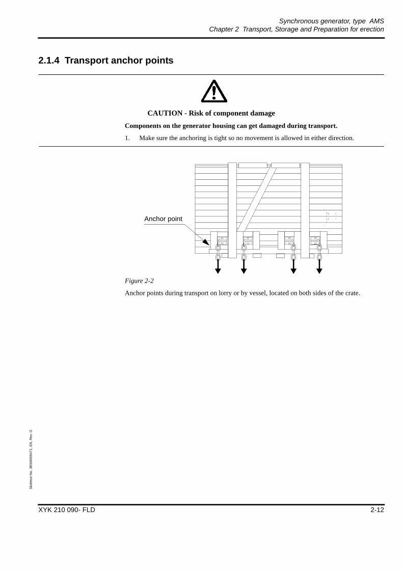
Synchronous generator, type AMSChapter 2 Transport, Storage and Preparation for erection
XYK 210 090- FLD 2-12
Skel
eton
No.
3B
SM00
5471
, EN
, Rev
. G
2.1.4 Transport anchor points
CAUTION - Risk of component damage
Components on the generator housing can get damaged during transport.
1. Make sure the anchoring is tight so no movement is allowed in either direction.
Figure 2-2
Anchor points during transport on lorry or by vessel, located on both sides of the crate.
Anchor point

Synchronous generator, type AMSChapter 2 Transport, Storage and Preparation for erection
XYK 210 090- FLD 2-13
Skel
eton
No.
3B
SM00
5471
, EN
, Rev
. G
2.1.5 Lifting of crated equipment
WARNING - Heavy lift
The crate with equipment is very heavy.
1. Use lifting equipment that is appropriate for the load.
2. Lifting must be performed with great care and using steel cables long enough to assure the angle requirements shown in Figure 2-3 on page 13. Centre of Gravity is shown on each crate.
Figure 2-3
2.1.6 UnpackingPlace the generator so that it is out of the way of any other goods handling and on a flat, vibration-free surface.
Remove top and sides of the wooden crate.
When the crating has been removed a check should be made to see that the generator is not damaged and that all accessories are included. Tick off the accessories on the packing list which is enclosed. Report immediately to the supplier if there is any damage, suspected damage or if accessories are missing.
60o
B
0.86xB
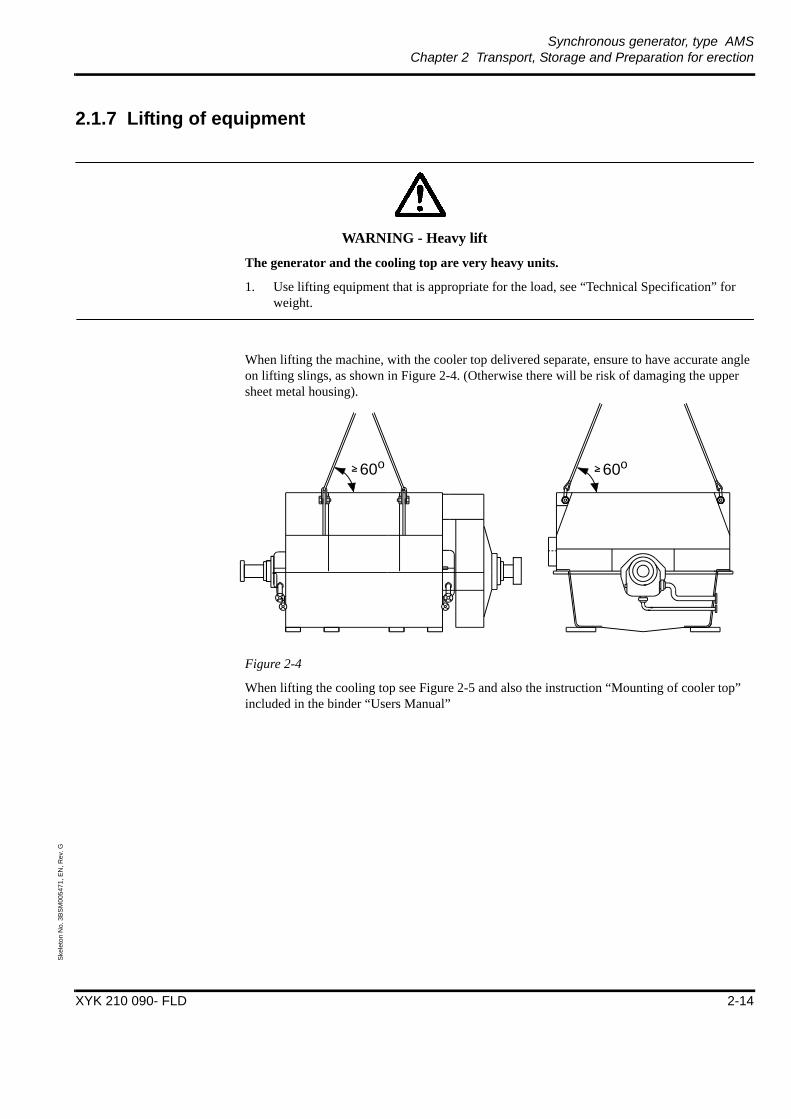
Synchronous generator, type AMSChapter 2 Transport, Storage and Preparation for erection
XYK 210 090- FLD 2-14
Skel
eton
No.
3B
SM00
5471
, EN
, Rev
. G
2.1.7 Lifting of equipment
WARNING - Heavy lift
The generator and the cooling top are very heavy units.
1. Use lifting equipment that is appropriate for the load, see “Technical Specification” for weight.
When lifting the machine, with the cooler top delivered separate, ensure to have accurate angle on lifting slings, as shown in Figure 2-4. (Otherwise there will be risk of damaging the upper sheet metal housing).
Figure 2-4
When lifting the cooling top see Figure 2-5 and also the instruction “Mounting of cooler top” included in the binder “Users Manual”
60o 60o
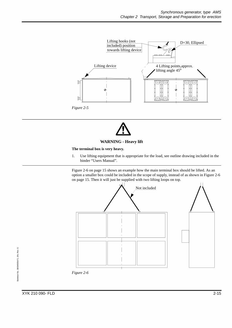
Synchronous generator, type AMSChapter 2 Transport, Storage and Preparation for erection
XYK 210 090- FLD 2-15
Skel
eton
No.
3B
SM00
5471
, EN
, Rev
. G
Figure 2-5
WARNING - Heavy lift
The terminal box is very heavy.
1. Use lifting equipment that is appropriate for the load, see outline drawing included in the binder “Users Manual”.
.
Figure 2-6 on page 15 shows an example how the main terminal box should be lifted. As an option a smaller box could be included in the scope of supply, instead of as shown in Figure 2-6 on page 15. Then it will just be supplied with two lifting loops on top.
Figure 2-6
Lifting device 4 Lifting points,approx.lifting angle 45o
D=30, EllipsedLifting hooks (not
towards lifting deviceincluded) position
Not included

Synchronous generator, type AMSChapter 2 Transport, Storage and Preparation for erection
XYK 210 090- FLD 2-16
Skel
eton
No.
3B
SM00
5471
, EN
, Rev
. G
2.2 Storage (this generator is prepared for long term storage)
2.2.1 Short term storage of crated generator
Storage < 9 month
Measures to be taken by customer or other part.
• The machine should be left in the crate.
• The crate should preferably be stored indoors and shall be placed on a vibration-free, flat and well-drained surface. If the crate is to be stored outdoors, the crate must be covered with a tarpaulin on the top extending at least 1 meter out from the crate to avoid direct rain on the crate.
• The crate should be kept dry, protected from rain and moisture.
Before commissioning the following items should be carried out:
• Visual external inspection of bearings and entering shaft
• Check insulation resistance in accordance with Section 5.3
2.2.2 Long term storage of crated generator
Storage > 9 month
Long-term storage must be notified before delivery, so that the machine can be prepared and packed for the actual condition. If an unscheduled long-term storage is needed, please contact ABB.
The machine should preferably be stored indoors and shall be placed on a vibration-free, flat and well-drained surface.
Measures to be taken by customer or other part.
If the machine is to be stored outdoors, it must be covered with a tarpaulin on the top extending at least 1 meter out from the crate to avoid direct rain on the machine.
1. Remove top and sides of the wooden crate. (Indoors)
2. Open the plastic protection to allow for a good ventilation.
3. If cooler top is delivered separate, the cooler top must be mounted immediately on the machine or if not applicable don’t remove the temporary transport covers. (Indoors)
4. The machine should be protected from rain and moisture. If the machine is stored in a harsh environment measures should be taken to protect it against dust and dirt.
5. To avoid condensation in the machine, the heating elements in main machine and exciter must be connected according to the circuit diagram, included in the binder “Users Manual”.
6. Check regularly the anti-corrosion coating on NOT painted areas like shaft, flanges etc. and touch up if necessary.
7. Measures should be taken to ensure that the heaters work properly at all time.
Synchronous generator, type AMSChapter 2 Transport, Storage and Preparation for erection
XYK 210 090- FLD 2-17
Skel
eton
No.
3B
SM00
5471
, EN
, Rev
. G
8. Corrosion preventive oil should be filled in the bearings, according to section 3.1 on page 22, once every 12 month. Rotation of the rotor is not required.
9. The axial transport-locking device must always be mounted during transportation of the machine.
Before commissioning the following items should be carried out:
• Visual external inspection of bearings and entering shaft.
• Visual inspection of exciter.
• Visual inspection of rotor and stator windings.
• The corrosion preventive oil in the bearings must be drained before rotation.
• Check insulation resistance in accordance with Section 5.3 .
2.2.3 Short term storage of uncrated generator
Storage < 9 month
The machine should preferably be stored indoors and shall be placed on a vibration-free, flat and well-drained surface.
Measures to be taken by customer or other part.
If the machine is to be stored outdoors, it must be covered with a tarpaulin on the top extending at least 1 meter out from the crate to avoid direct rain on the machine and be placed on at least 100 mm high rigid supports, as to make sure that no water can enter the machine from below.
1. Open the plastic protection to allow for a good ventilation.
2. If cooler top is delivered separate, the cooler top must be mounted immediately on the machine or if not applicable don’t remove the temporary transport covers. (Indoors)
3. The machine should be protected from rain and moisture. If the machine is stored in a harsh environment measures should be taken to protect it against dust and dirt.
4. To avoid condensation in the machine, the heating elements in main machine and exciter must be connected according to the circuit diagram, included in the binder “Users Manual”.
5. Check regularly the anti-corrosion coating on NOT painted areas like shaft, flanges etc. and touch up if necessary.
6. Measures should be taken to ensure that the heaters work properly at all time.
7. The axial transport-locking device must always be mounted during transportation of the machine
Before commissioning the following items should be carried out:
• Visual external inspection of bearings and entering shaft.
• Check insulation resistance in accordance with Section 5.3 .
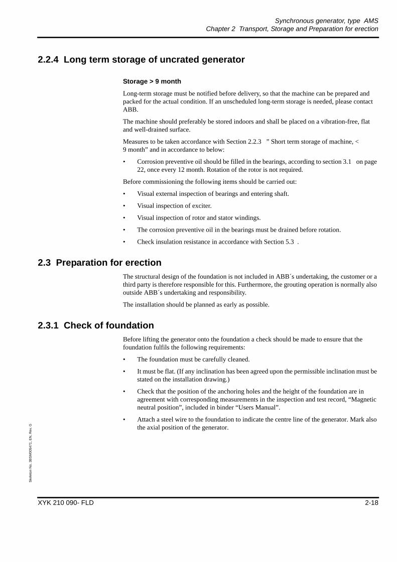
Synchronous generator, type AMSChapter 2 Transport, Storage and Preparation for erection
XYK 210 090- FLD 2-18
Skel
eton
No.
3B
SM00
5471
, EN
, Rev
. G
2.2.4 Long term storage of uncrated generator
Storage > 9 month
Long-term storage must be notified before delivery, so that the machine can be prepared and packed for the actual condition. If an unscheduled long-term storage is needed, please contact ABB.
The machine should preferably be stored indoors and shall be placed on a vibration-free, flat and well-drained surface.
Measures to be taken accordance with Section 2.2.3 ” Short term storage of machine, < 9 month” and in accordance to below:
• Corrosion preventive oil should be filled in the bearings, according to section 3.1 on page 22, once every 12 month. Rotation of the rotor is not required.
Before commissioning the following items should be carried out:
• Visual external inspection of bearings and entering shaft.
• Visual inspection of exciter.
• Visual inspection of rotor and stator windings.
• The corrosion preventive oil in the bearings must be drained before rotation.
• Check insulation resistance in accordance with Section 5.3 .
2.3 Preparation for erectionThe structural design of the foundation is not included in ABB´s undertaking, the customer or a third party is therefore responsible for this. Furthermore, the grouting operation is normally also outside ABB´s undertaking and responsibility.
The installation should be planned as early as possible.
2.3.1 Check of foundationBefore lifting the generator onto the foundation a check should be made to ensure that the foundation fulfils the following requirements:
• The foundation must be carefully cleaned.
• It must be flat. (If any inclination has been agreed upon the permissible inclination must be stated on the installation drawing.)
• Check that the position of the anchoring holes and the height of the foundation are in agreement with corresponding measurements in the inspection and test record, “Magnetic neutral position”, included in binder “Users Manual”.
• Attach a steel wire to the foundation to indicate the centre line of the generator. Mark also the axial position of the generator.

Synchronous generator, type AMSChapter 2 Transport, Storage and Preparation for erection
XYK 210 090- FLD 2-19
Skel
eton
No.
3B
SM00
5471
, EN
, Rev
. G
2.3.2 Vertical and horizontal positioning
CAUTION - Risk of personal injury
Use a piece of carboard to insert the shims under the generator to avoid jamming your fingers if the jacks should fail.
The vertical positioning of the generator is made with hydraulic jacks (optional equipment) placed as tight as possible to the two footplates in the middle and tight to the two outer footplates as shown in Figure 2-7 on page 19 and Figure 2-8 on page 20. As alternative if vertical adjustment screws are included the vertical positioning of the generator is made with them.
ABB AB, Machines´s delivery includes shims with 1 mm thickness, placed as shown in Figure 2-9 on page 20. Shims needed with other thicknesses are to be provided by the customer.
Bracket plates, with adjusting screws for horizontal positioning of the generator are placed on the sole plates, as shown in Figure 2-7 on page 19.
Figure 2-7
CL
Bracket w.adj. screw
Hydraulic jack
Guiding pin
only on D-end
Guiding pin
only on D-end
Vertical adjustmentscrews, if included
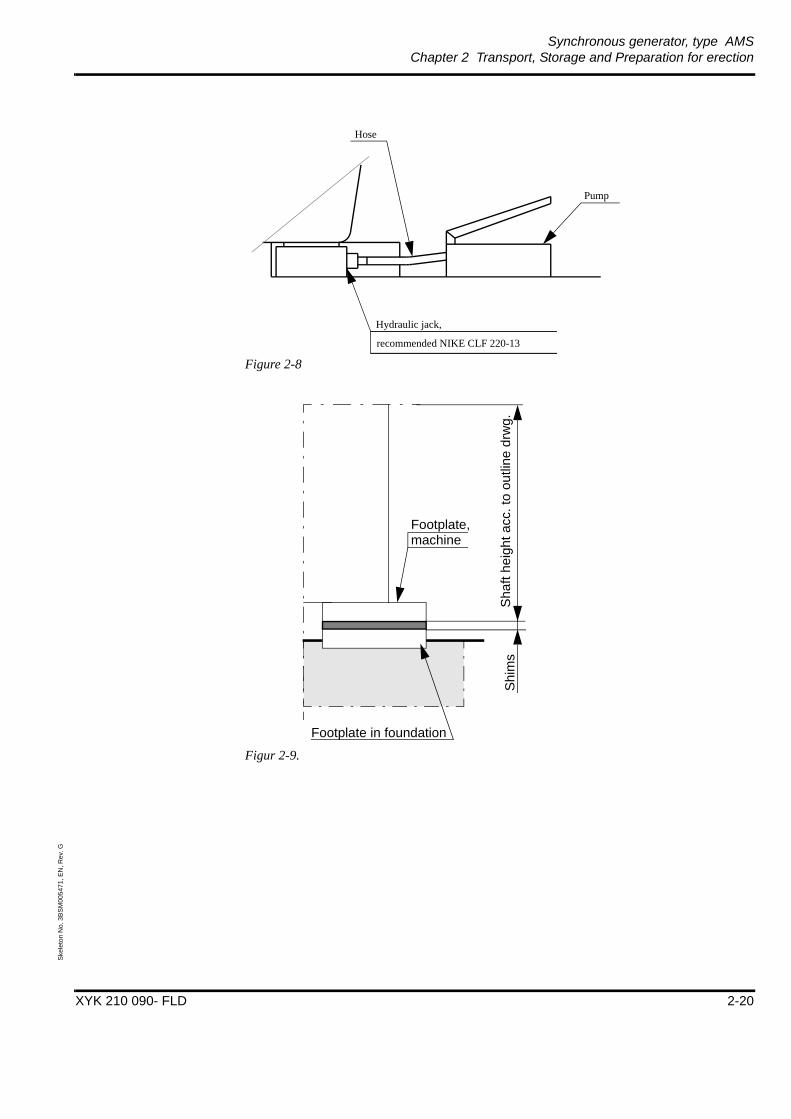
Synchronous generator, type AMSChapter 2 Transport, Storage and Preparation for erection
XYK 210 090- FLD 2-20
Skel
eton
No.
3B
SM00
5471
, EN
, Rev
. G
Figure 2-8
Figur 2-9.
Hydraulic jack,
recommended NIKE CLF 220-13
Pump
Hose
Sha
ft he
ight
acc
. to
outli
ne d
rwg.
Shi
ms
Footplate, machine
Footplate in foundation

Synchronous generator, type AMSChapter 2 Transport, Storage and Preparation for erection
XYK 210 090- FLD 2-21
Skel
eton
No.
3B
SM00
5471
, EN
, Rev
. G
2.3.3 Removal of the transport locking device• The transport locking device is clamped to the shaft and bolted to the drive end side of the
generator. The transport locking device consists of a divided clamp ring which locks the rotor against axial movements and rotation. See Figure 2-10 on page 21.
• Remove the screws which are screwed into the bearing housing.
• Remove the screws which hold the two halves of the locking device together.
• Lift off the transport locking device carefully. (Save the locking device for future needs).
Figure 2-10

Synchronous generator, type AMSChapter 3 Alignment
XYK 210 090- FLD 3-22
Skel
eton
No.
3B
SM00
5472
, EN
, Rev
. F
Chapter 3 Alignment
Introduction
Good planning and preparation result in fast, simple and correct installation. Safe running conditions with maximum of accessibility are assured.
3.1 Preparations for generator installationAuxiliary tools for the erection should be made and assembled at site if required:
• Suitable material for set-up and shimming as well as other auxiliary tools for erection are normally not included in ABB's delivery. (Auxiliary tools for erection, like hydraulic jack and bracket plates with adjusting screws, can be purchased from ABB as generator accessory.)
• Attachments for gauges, extension brackets and other alignment tools are to be made.
• Before the rotor is turned, oil must be poured into the bearings, by using an extender piping connected to the oil inlet pipe on the bearing . The funnel has to be placed above the bearing as the Figure 3-1 on page 22 shows. The outlet pipe should be open.
Figure 3-1.
A simple lever is needed for turning the rotor. While turning the rotor, oil must be continuously poured into the funnels at both end of the generator.
• If the generator is to be erected outdoors, sun and rain protection must be provided to eliminate measuring errors.
NOTE: When the surroundings are neither heated nor dry, heating equipment must be provided.
Connect to the oil inlet pipe
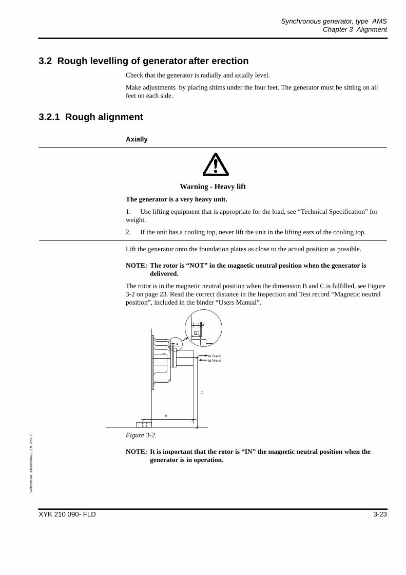
Synchronous generator, type AMSChapter 3 Alignment
XYK 210 090- FLD 3-23
Skel
eton
No.
3B
SM00
5472
, EN
, Rev
. F
3.2 Rough levelling of generator after erectionCheck that the generator is radially and axially level.
Make adjustments by placing shims under the four feet. The generator must be sitting on all feet on each side.
3.2.1 Rough alignment
Axially
Warning - Heavy lift
The generator is a very heavy unit.
1. Use lifting equipment that is appropriate for the load, see “Technical Specification” for weight.
2. If the unit has a cooling top, never lift the unit in the lifting ears of the cooling top.
Lift the generator onto the foundation plates as close to the actual position as possible.
NOTE: The rotor is “NOT” in the magnetic neutral position when the generator is delivered.
The rotor is in the magnetic neutral position when the dimension B and C is fulfilled, see Figure 3-2 on page 23. Read the correct distance in the Inspection and Test record “Magnetic neutral position”, included in the binder “Users Manual”.
Figure 3-2.
NOTE: It is important that the rotor is “IN” the magnetic neutral position when the generator is in operation.
A
to D-endto N-end
A
B
C

Synchronous generator, type AMSChapter 3 Alignment
XYK 210 090- FLD 3-24
Skel
eton
No.
3B
SM00
5472
, EN
, Rev
. F
3.3 GroutingWhen the generator has been properly aligned, its base elements are attached to the foundation by grouting. Use only non-shrinking concrete for grouting to ensure proper adhesion between the base frame and grouting. Make sure that the grouting fills properly the whole space around and under the base element. Do not use a vibrator in order to avoid any disturbance in the alignment.
After the grouting has set (cured), adjust vertically to the final elevation by putting shims between the base frame and the base element. Check also the other alignments of the generator and adjust, if necessary.
Non-shrink grout is recommended for the best results. For shaping and grouting, the manufacturers instructions to be followed.

Synchronous generator, type AMSChapter 3 Alignment
XYK 210 090- FLD 3-25
Skel
eton
No.
3B
SM00
5472
, EN
, Rev
. F
3.4 Correction for thermal expansionTemperatures have a considerable influence and should be considered during the alignment. The temperature of the generator is lower during erection than it will be under operating conditions. For this reason the shaft centre is going to lie higher during operating conditions.
Depending on the type of coupling, the distance between the generator and driven equipment, etc. compensating alignment may be necessary.
The vertical movement of the shaft of due to thermal expansion the electrical generator is in acc. to drawing “shaft displacement”, included in the binder “Users Manual”.
3.5 Final alignment and inspectionAfter the generator has been roughly positioned, as described before, the final alignment can start.
Lubricate the bearings at regular intervals during the final alignment in accordance with section 3.1 on page 22.
The normal fault tolerance for alignment which ABB accepts is below 0.1 mm at operating temperature.
Figure 3-3.
The tolerances given by the coupling manufacturers must not be used in deciding how accurate the alignment should be because these tolerances indicate what the coupling can accept. Excessive tolerances will give rise to vibrations, bearing damage etc. and therefore should tolerances as narrow as recommended above be aimed at.
Finally check the axial distance between the two coupling halves.
An alignment record should be drawn for future checks.
Radial misalignment
Gap (angular displacement)
Axial displacement
Δr
Δb
Δa

Synchronous generator, type AMSChapter 4 Mechanical and electrical installation
XYK 210 090- FLD 4-26
Skel
eton
No.
3B
SM00
5473
, EN
, Rev
. E
Chapter 4 Mechanical and electrical installation
4.1 Mechanical installation
4.1.1 Cooling arrangement
Air to water
If the cooler housing is delivered separately the following action needs to be taken:
1. Remove the transport roof on the generator.
WARNING - Heavy lift
The cooler housing is a heavy unit.
1. Use lifting equipment that is appropriate for the load, see “ Outline drawing” for weight.
2. Lift the cooler housing over the generator. Connect the hoses for the water leakage detector to the cooler drain, according to drawing 3BSM 001483-A .
3. Lower the cooler housing until it’s almost resting on the generator (if possible), this will make it easier to adjust the housing to the generator. After all the bolts have been put in place lower the housing completely and tighten the bolts.
4. Connect the cooler pipes.
– The cooling water pipes shall be laid so that they do not obstruct service and maintenance. The water pipes should be designed so that only a short part needs to be dismantled to allow cooler removal.
– The piping should be designed so that no stress is applied to the cooler flanges. Before the pipes are connected to the cooler they should be properly cleaned.
4.1.2 Connection of oil pipesThe bearings are made for flood lubrication, the inlet pipe can be provided with an orifice to avoid overfilling.
The return pipes should have an incline of 40-50 mm/m in order to guarantee trouble-free oil circulation. The oil pipes should be designed so that they do not obstruct service and maintenance. The pipes should be designed so that no stress is applied to the flanges on the generator.
Synchronous generator, type AMSChapter 4 Mechanical and electrical installation
XYK 210 090- FLD 4-27
Skel
eton
No.
3B
SM00
5473
, EN
, Rev
. E
WARNING - Oil leakage
Flushing with the bearings connected might cause oil leakage.
1. Bypass the generator before flushing the oil system.
For required oil flow and pressure see outline drawing. The oil pipes should be carefully flushed before they are connected to the generator.
4.1.3 Mounting of main terminal box
CAUTION - Component damage
Great care should be taken when handling the main terminal box as it contains delicate equipment.
To be able to transport the machine the main terminal box for the high voltage connection is delivered separately and must be fitted at site.
The terminal should be supported so that no stress is applied to the generator.
1. Remove the protection cover fitted over the generator bushings.
2. Level the main terminal box so that no stresses will be induced to the generator bushings when they are connected to the busbars in the main terminal box.
3. The joint between the main terminal box and the generator should be tightened according to instruction 3BSM 001263R0001, included in the binder “Users manual”.
4. Before the high voltage cables are connected to the main terminal box the insulation resistance (megged) should be checked. Check both the generator insulation resistance (stator winding resistance) and the insulation resistance of the main terminal box according to instruction in Section 5.3 .
5. The joint between the main terminal box and the generator should be insulated according to instruction 3BSM 004941, included in the binder “Users manual”.
The insulation material has to be stored cold. For that reason it must be bought locally, ABB AB, Machines can not supply the insulation.

Synchronous generator, type AMSChapter 4 Mechanical and electrical installation
XYK 210 090- FLD 4-28
Skel
eton
No.
3B
SM00
5473
, EN
, Rev
. E
4.2 Electrical installation
4.2.1 Connection of control equipmentFor terminal box location and content see outline drawing (included in binder “Users manual”). Connections should be made according to circuit diagram.
NOTE: Space heaters in exciter and stator should be connected as soon as possible after unpacking. If the permanent supply is not available a temporary supply should be connected.
4.2.2 Connection of high voltage cablesThe high-voltage cables are connected according to the terminal markings. Striping, splicing and insulation of the high voltage cables should be performed according to the instructions from the cable manufacturer.
The high voltage cables are connected according to the terminal markings. The stator insulation resistance should be checked before final connection of the cables.
Neutral point connection inside the cubicle.
4.2.3 Earth connectionThe earth lead may be connected either inside or outside the terminal box and to both sides of the generator.
For connection points on the generator see outline drawing (included in binder “Users manual”).

Synchronous generator, type AMSChapter 5 Commissioning
XYK 210 090- FLD 5-29
Skel
eton
No.
3B
SM00
5474
, EN
, Rev
. F
Chapter 5 Commissioning
On the commissioning personnel lies a great responsibility for a safe and trouble free operation of the generator during its lifetime.
Commissioning should only be made by qualified personal.
The following are tests and checks on the generator that are recommended by the manufacturer. If other tests are to be performed, the manufaturer should be consulted.
5.1 Check of mechanical installation
Check alignment of the generator prior to commissioning.
• Go through the alignment report and ensure that if the generator is accurately aligned according to ABB AB, Machines´s alignment specifications. See Chapter 3 Alignment.
• Alignment protocol should always be included in the commissioning report.
Check that the generator is properly anchored to the foundation.
• Check for cracks in the foundation and the general condition of the foundation.
Bearing insulation
• “Megging” of bearings should be performed before the generator is coupled to the turbine . See section 5.3 on page 31.
Other checks• Open the generator at both ends and check that no loose parts are present inside the
generator. Check that no parts have come loose during transportation and that the air-gap is free.
• If possible, turn the rotor and make sure that the rotor turns freely and that no abnormal sound can be heard. See section 3.1 on page 22.
• Check the airgap between the exciter stator and rotor, see the test record “Air gap measurement” (included in binder “Users manual”).
WARNING - Magnetic force
There are very strong magnetic forces between the PMG rotor and stator.
1. Remove your own wrist watch, credit cards and other digital equipment before working around those strong magnetic forces.
2. Personnel with pace maker should not be working in the vicinity of the PMG.
• Check the air gap between the PMG stator and rotor, see the test record “Air gap measurement” (included in binder “Users manual”).
Synchronous generator, type AMSChapter 5 Commissioning
XYK 210 090- FLD 5-30
Skel
eton
No.
3B
SM00
5474
, EN
, Rev
. F
NOTE: The lubrication system must be commissioned and running before the rotor is turned.
• Check the assembly of the main terminal box and cooling system.
• Check pressure and flow for oil and cooling system according to outline drawing (included in binder “Users manual”).
5.2 Check of electrical installationWhen the stator has been megged (See section 5.3 on page 31) the cables can be permanently connected to the busbars in the main terminal box.
Check connection of high-voltage cables observing the following.• Make sure the busbars and insulators do not have any cracks or other damage.• Check the the bolt connections between stator busbars and terminal box, and make sure it
has been tightened with a torque wrench and that a spring washer has been used.
• Check all busbars, insulators and connections in terminal box.• Make sure the incoming high-voltage cables are suitably routed and the bracing suitably
carried out.• Make sure the incoming cables are stress-relieved in a proper way.
• Check phase sequence of incoming cables.

Synchronous generator, type AMSChapter 5 Commissioning
XYK 210 090- FLD 5-31
Skel
eton
No.
3B
SM00
5474
, EN
, Rev
. F
5.3 Electrical checksBearing insulation resistance check
WARNING - High voltage
This work involves the main circuits of the generator normally connected to the high voltage supply net. Before you start to work:
1. Make sure the generator is disconnected from the high voltage net and that the circuit breaker is locked in the open position so it not accidentally (or otherwise) can be closed during the measurements.
2. Note also that capacitors can contain dangerous voltages, so be sure to ground all details before you touch them.
All connections of control equipment are to be checked and function tested.
A bearing insulation check should be carried out before the generator is connected to theturbine .
Remove the earth device located on the bearing on the drive end side. Megger the shaft to ground using no more than 500 Volt DC. See Figure 5-1 on page 31 and Figure 5-2 on page 32.
Figure 5-1
Loosen the hub for the
out the earth connectorand connect for megging
earth device and pull

Synchronous generator, type AMSChapter 5 Commissioning
XYK 210 090- FLD 5-32
Skel
eton
No.
3B
SM00
5474
, EN
, Rev
. F
Figure 5-2
Insulation resistance is acceptable if the megger value is more than 1 Mohm.

Synchronous generator, type AMSChapter 5 Commissioning
XYK 210 090- FLD 5-33
Skel
eton
No.
3B
SM00
5474
, EN
, Rev
. F
General for rotor and stator
The winding shall be dry during the test and therefore the standstill heating elements should have been active for at least some days before the megging is performed.
The winding temperature should also be recorded. According to normal standards the winding insulation resistance is to be stated at a winding temperature of 40 o C. The value measured is therefore converted to a corresponding 40 o C-value, with the help of the following diagram.
Recommended minimum insulation resistance at 40oC must exceed the following value
R(40)> U+1 MohmWhere R(40)= Equivalent insulation resistance at 40 oC.U = Rated generator voltage in kV (stator or rotor).The insulation resistance of a new generator, having a clean and dry winding, is considerably higher as will be found in the test report of the generator.If the measured value is considered too low the winding must be cleaned and/or dried.
(0.25)-
Conversion factor, k
R40 = 0.25x30=7.5 MΩk = 0.25R = 30 MΩ measured at 20oCExample:R40 = k x R
R40 = Equivalent insulation resistance at 40oCR = Megger-value at a specific temperature
when meggeringWinding temperature
100
50
10
5
1
0.5
0.1
0.05
(oC)806040100-10 20 30 50 70 90 10014 32 50 68 86 104 122 140 158 176 194 212 (oF)

Synchronous generator, type AMSChapter 5 Commissioning
XYK 210 090- FLD 5-34
Skel
eton
No.
3B
SM00
5474
, EN
, Rev
. F
Main stator winding insulation resistance check
WARNING - High voltage
This work involves the main circuits of the generator normally connected to the high voltage supply net. Before you start to work:
1. Make sure the generator is disconnected from the high voltage net and that the circuit breaker is locked in the open position so it not accidentally (or otherwise) can be closed during the measurements.
2. Note also that capacitors can contain dangerous voltages, so be sure to ground all details before you touch them.
3. When testing the insulation resistance of the stator winding disconnect the surge capacitors, lighting arresters and the fuses to the PT’s, if such equipment is installed.
4. If a neutral resistor is installed be sure that it is disconnected.
5. Be sure that the secondary connections of the CT’s and spare cores ARE NOT OPEN.
Megging should be performed in the terminal box and from the synchronizing circuit breaker (when the high voltage cables has been connected).
If the insulation resistance is low when measuring from the synchronizing circuit breaker, disconnect high voltage cables and perform the megging direct on the terminals in the terminal box.
A 5000 Volt DC megger should be used. Reading should be made after 1 minute.
Main stator Polarization Index check
The Polarization Index Test (dielectric absorption test) is an extension of the conventional one-minute resistance test, where the testing time is extended to 10 minutes. To make the test a motor-driven or an electronic megger is necessary to give a sufficiently steady voltage during the testing.
The insulation resistance shall be read every minute.
The ration of the resistance value after 10 minutes to the resistance value after 1 minute is called the Polarization Index.
The Polarization Index should exceed ≥ 2.
Field circuit insulation resistance (main- and exciter rotor)
Meggering should be performed at the exciter rotor connection to the main rotor.
A 500 V DC megger should be used. Reading should be made after 1 minute.
R10R1
R1 = Insulation resistance after 1 - minute
R10 = Insulation resistance after 10- minute
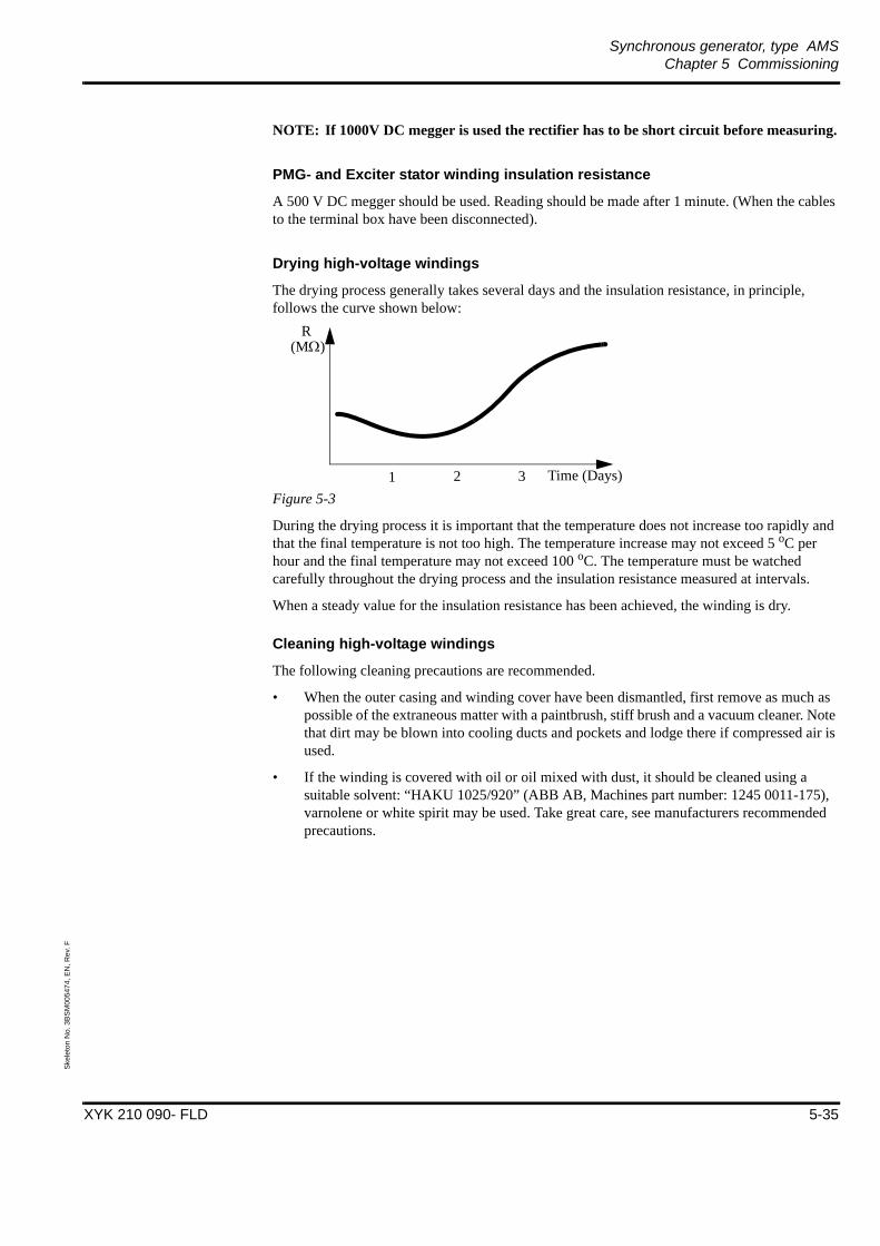
Synchronous generator, type AMSChapter 5 Commissioning
XYK 210 090- FLD 5-35
Skel
eton
No.
3B
SM00
5474
, EN
, Rev
. F
NOTE: If 1000V DC megger is used the rectifier has to be short circuit before measuring.
PMG- and Exciter stator winding insulation resistance
A 500 V DC megger should be used. Reading should be made after 1 minute. (When the cables to the terminal box have been disconnected).
Drying high-voltage windings
The drying process generally takes several days and the insulation resistance, in principle, follows the curve shown below:
Figure 5-3
During the drying process it is important that the temperature does not increase too rapidly and that the final temperature is not too high. The temperature increase may not exceed 5 oC per hour and the final temperature may not exceed 100 oC. The temperature must be watched carefully throughout the drying process and the insulation resistance measured at intervals.
When a steady value for the insulation resistance has been achieved, the winding is dry.
Cleaning high-voltage windings
The following cleaning precautions are recommended.
• When the outer casing and winding cover have been dismantled, first remove as much as possible of the extraneous matter with a paintbrush, stiff brush and a vacuum cleaner. Note that dirt may be blown into cooling ducts and pockets and lodge there if compressed air is used.
• If the winding is covered with oil or oil mixed with dust, it should be cleaned using a suitable solvent: “HAKU 1025/920” (ABB AB, Machines part number: 1245 0011-175), varnolene or white spirit may be used. Take great care, see manufacturers recommended precautions.
1 2 3 Time (Days)
(MΩ)R
Synchronous generator, type AMSChapter 5 Commissioning
XYK 210 090- FLD 5-36
Skel
eton
No.
3B
SM00
5474
, EN
, Rev
. F
5.4 Before the first start attemptCheck that the Motor Excitation Control Panel (MCP) is equipped for starting this type of motor.
The motor must be started and synchronized with reluctance torque. The field current must be applied after synchronization.
Correct procedure is to measure the stator current during the start to set correct time for field apply see startprocedure curve according to the technical specification included in binder “Users manual”.
Stator voltage, stator current and field current to exciter stator need to be recorded versus time during the commissioning.
5.5 The first start attemptsDuring the first starts of a synchronous motor the following parameters should be observed, noted and included in the commissioning report.
• Starting time
• Starting current
• Voltage drop
• Time after start when field current is applied
• Vibration levels.
5.5.1 Start interlockingIf the lubricating or cooling systems are provided with pressure or flow monitors, should these also be included in the start interlocking systems.
A counter for the number of start up and a duty time meter should be included in the equipment.
5.6 Checks during running of the generatorDuring the first hours/days of running it is important to keep a close surveillance of the generator in case of any changes in vibration or temperature levels or abnormal sounds should occur.Check the connection of oil and cooling water pipes and check for leaks when running the generator.

Synchronous generator, type AMSChapter 5 Commissioning
XYK 210 090- FLD 5-37
Skel
eton
No.
3B
SM00
5474
, EN
, Rev
. F
5.6.1 Normal vibration levelsThe vibration levels given in the table below is intended for protecting the generator from damage during operation and indicating normal and acceptable levels. Please note that transient conditions, such as starting or synchronization, are excluded from these recommendations.
Important for vibration monitoring is to detect deviations from normal levels during operation, and the following guidlines are recommended:
• Set the alarm level at 2 times the normal level during operation
• Set the trip level at 4 times the normal level during operation
The alarm and trip levels should in no case be above what is given in the tables below.
Example: The normal vibration level during operation at site is 1.5 mm/s. The alarm level should then be set at 3 mm/s, and the trip level at 6 mm/s.
5.6.1.1 Bearing housings
Table 5-1: Acceptable vibration levels for bearing housings. The values are valid for all speeds.(Measured frequency range 10-1000 Hz)
5.6.1.2 Structural vibrationsThe following values are valid for structural vibrations in the supporting structure of the generator, covers etc are excluded.
Table 5-2: Acceptable vibration levels for supporting structures. The values are valid for allspeeds. (Measured frequency range 10-1000 Hz)
Vertical/horizontal Axial
mm/s rms
in/sec rms
micronp-p
mills p-p
mm/srms
in/sec rms
micronp-p
mills p-p
Testroom (typical) 1.8 0.07 32.4 1.3 2.3 0.9 41.4 1.63
Alarm 4.5 0.18 81.0 3.2 7.0 0.28 126.0 5.0
Trip 8.0 0.31 144.1 5.7 15.0 0.59 270.1 10.6
Vertical/horizontal Axial
mm/s rms
in/sec rms
micronp-p
mills p-p
mm/srms
in/sec rms
micronp-p
mills p-p
Testroom (typical) 4.5 0.18 81.0 3.2 4.5 0.18 81.0 3.2
Alarm 7.0 0.28 126.0 5.0 11.0 0.43 198.1 7.8
Trip 15.0 0.59 270.1 10.6 20.0 0.79 360.1 14.2

Synchronous generator, type AMSChapter 5 Commissioning
XYK 210 090- FLD 5-38
Skel
eton
No.
3B
SM00
5474
, EN
, Rev
. F
5.6.1.3 Shaft vibrationsThe following values are valid for shaft vibrations measured with eddy-current probes.
Table 5-3: Acceptable vibration levels for shaft vibrations. The values are valid for all speeds.
5.6.2 Temperature levelsThe temperatures of the bearings and stator winding and air should be checked when the generator is running for the first time.
The bearings reach a stable temperature after about 45 to 60 minutes when running at full speed if the temperature of the oil to the bearings is about 40 oC.
The stator winding temperature depends on the load of the generator. If full load cannot be obtained during or soon after commissioning, the present load and temperature should be noted and included in the commissioning report.
Recommended settings for alarm and trip levels, see the test record “Setting List” included in the binder “Users manual”.
5.7 Check listThe following checklist and protocols should be completed during commissioning and returned to ABB AB, Machines toghether with the commissioning report after completed commissioning.
Checks to be made during operation, please see Chapter 6 Operation.
Vertical/horizontal
mm/s rms
in/sec rms
micronp-p
mills p-p
Testroom (typical) - - 50.8 2.0
Alarm - - 76.2 3.0
Trip - - 101.6 4.0
Synchronous generator, type AMSChapter 5 Commissioning
XYK 210 090- FLD 5-39
Skel
eton
No.
3B
SM00
5474
, EN
, Rev
. F
5.7.1 Page 1
o First run up, date .....................................o Direction of rotation: clockwise (Seen from D-end)
o Direction of rotation: counterclockwise (Seen from D-end)
o No abnormal noise
Comments ...............................................................................................................................................................
................................................................................................................................................................
o Second run up (to full speed), date ................................Starting time ............................. s
Retardation time .................. min
Comments ...............................................................................................................................................................
...............................................................................................................................................................
Generator data
Customer: Name and company of responsible commissioning engineer:Site name:Serial number: Order number: Date:
Output: kVA Power factor: Voltage: V
Frequency: Hz Speed: r/min Current: A
Excitation: V A Oil quality:

Synchronous generator, type AMSChapter 5 Commissioning
XYK 210 090- FLD 5-40
Skel
eton
No.
3B
SM00
5474
, EN
, Rev
. F
5.7.2 Page 2Customer: Name and company of responsible commissioning engineer:Site name:Serial number: Order number: Date:
Time Bearing temp.(oC)
Inlet Oil Vibr. (mm/s, μm)
Winding temp.(oC)
Coolingair/water
CommentsVibrations, noise, etc.
D-side
N-side
(oC) (l/s) D-side
N-side
max min m3/h oC

Synchronous generator, type AMSChapter 5 Commissioning
XYK 210 090- FLD 5-41
Skel
eton
No.
3B
SM00
5474
, EN
, Rev
. F
5.7.3 Page 3Customer: Name and company of responsible commissioning engineer:Site name:Serial number: Order number: Date:
Time Stator Exciter Field (A)
Load(MW)
CommentsVibrations, noise, etc.
(A) (cosϕ) (V)

Synchronous generator, type AMSChapter 6 Operation
XYK 210 090- FLD 6-42
Skel
eton
No.
3B
SM00
5475
, EN
, Rev
. E
Chapter 6 Operation
6.1 Start up procedureBefore start up of the generator a check has to be made that:
– Beware that all protection covers and other equipment is correctly installed and that no person is close to voltage carrying equipment or rotating parts.
– Authorization has been given to start and that there is no risk of personal or property damage.
– Required oil supply is fulfilled in accordance to drawing “Outline synchronous generator”, included in the binder “Users Manual”.
– Required cooling media is fulfilled in accordance to drawing “Outline synchronous generator”.
– No shut down means are in operation.
– Personnel and equipment associated to the generator are ready for start up of generator.
6.2 Continuous supervisionThe operating personnel should inspect the generator at regular intervals.
This means that they should listen, feel and smell the generator and its associated equipment in order to obtain a feeling for normal operating condition.
The object of the supervision inspection is to thoroughly familiarize personnel with the equipment. This is imperative if abnormal occurrences are to be detected and remedied in time.
It is therefore recommended that a “supervision inspection sheet”(attached) will be filled in.
Data from a supervision inspection should be kept for future reference and can be of great help at maintenance work, trouble shooting and repairs.
The programme for suitable supervision inspections can be found below.
The border between supervision and maintenance is rather diffuse. Normal supervision of operation includes logging of operating data such as load, temperatures etc., and the comments made are used as a basis for maintenance and service.
• During the first period of operation (- 200 hours) supervision should be intensive. Temperature of bearing and winding, load, current, cooling, lubrication and vibration shall be checked frequently and logged.
• During the following duty period (200 - 1000 hours) a check-up once a day is sufficient. A record of supervision inspection should be used and filed with the customer. Thereafter the time between inspections may be further extended if operation is continuous and stable.
Synchronous generator, type AMSChapter 6 Operation
XYK 210 090- FLD 6-43
Skel
eton
No.
3B
SM00
5475
, EN
, Rev
. E
6.3 Shut down proceduresDuring shutdown of the generator, lubrication oil and cooling media supply has to be ensured.
When the generator not is in operation, cooling water has to be switched off and the anticondensation heaters to be switched on. Those actions are to be made to avoid condensation within the generator.
6.4 Alarm during operationIf alarm during operation e.g.:
• Cooling
• Water
• Lubrication
• Temperature
• Vibration
• etc.
The generator has to be unloaded and deenergized (triped).
After coasting down the generator make necessary investigation to find out the reason for the alarm before next start.
Synchronous generator, type AMSChapter 6 Operation
XYK 210 090- FLD 6-44
Skel
eton
No.
3B
SM00
5475
, EN
, Rev
. E
RECOMMENDED SUPERVISION INSPECTION SHEET (2 pages)
Customer: Name and company of responsible commissioning engineer:Site name:Serial number: Order number: Date:
Time Bearing temp.(oC)
Inlet Oil Vibr. (mm/s, μm)
Winding temp.(oC)
Coolingair/water
CommentsVibrations, noise, etc.
D-side
N-side
(oC) (l/s) D-side
N-side
max min m3/h oC
Synchronous generator, type AMSChapter 6 Operation
XYK 210 090- FLD 6-45
Skel
eton
No.
3B
SM00
5475
, EN
, Rev
. E
Customer: Name and company of responsible commissioning engineer:Site name:Serial number: Order number: Date:
Time Stator Exciter Field (A)
Load(MW)
CommentsVibrations, noise, etc.
(A) (cosϕ) (V)

Synchronous generator, type AMSChapter 7 Maintenance
XYK 210 090- FLD 7-46
Skel
eton
No.
3B
SM00
5477
, EN
, Rev
. F
Chapter 7 Maintenance
7.1 Preventive maintenanceA generator often forms an important part of a larger installation and if it is supervised and maintained properly it will be much more reliable in operation.
The border between supervision and maintenance is rather diffuse. Normal supervision of operation includes logging of operating data such as load, temperatures etc., and the comments made are used as a basis for maintenance and service.
After commissioning or maintenance supervision should be intensive. Temperature of bearing and winding, load, current, cooling, lubrication and vibration shall be checked frequently.
Local condition has to be considered when decision of maintenance interval and level.
7.2 Before all maintenance workSafety precaution
WARNING - Risk of personal injury
Before any maintenance or test is performed the following must be done:
1. The generator must be completely stopped, dead, disconnected and grounded before any inspection covers are opened on the generator.
2. Before working on any electrical equipment, general electrical safety precautions are to be taken and local regulation are to be respected, according to instructions of the customers personnel in charge of security, in order to prevent personnel accidents.
3. Employees who perform maintenance on electrical equipment and installations shall be qualified persons as required and shall be trained in and familiar with the specific maintenance procedures and tests required.
Preparation and preplanning of maintenance
Preparation and preplanning is recommended before all maintenance, special level 3 and 4.
Requirements of:
• Lifting capacity.
• Tools including rotor removal at level 4.
• Manpower and needed competence.
• Spare parts and other overhaul kit (replacement and consumables).

Synchronous generator, type AMSChapter 7 Maintenance
XYK 210 090- FLD 7-47
Skel
eton
No.
3B
SM00
5477
, EN
, Rev
. F
7.3 Recommended maintenance program
Option: Diagnostic insulation test of the stator winding.
Maintenance program Level 1 (L1) Level 2 (L2) Level 3 (L3) Level 4 (L4)
Intervalmax. 10 000h (equivalent
hours) of operation or yearly
max. 20 000h (equivalent hours) of operation
or max. 3 years
max 40 000h (equivalent hours) of operation
or max. 6 years
max 80 000h (equivalent hours) of operation or max. 12 years
Preparation for inspection
Open inspection covers. Open inspection covers. Disassembly covers.Disassembly PMG stator.Open bearings.Open water coolers.
Open bearings.Removal rotor and exciter.Open water coolers.
Instrument/Tools
Megger, stator.Megger, rotor.
Megger, statorMegger, rotorFibre-optic or video borescope.Oscilloscope/Test equipment.
Megger, stator.Megger, rotor.Rotor removal equipment.Torque wrench.Oscilloscope/Test equipment.
Parts/Spare parts
Bearing liners, Brushes, Air-lock filter (bearing),Control pulse unit, Thyristors, Diodes.Other order specific parts.
Acc. to L1 and suggestion from inspection L1.Silicon tape.
Acc. to L2 and suggestion from inspection L1 and L2. Water cooler.Rectifier kit.Bearing kit.Gaskets.
Acc. to L3 and suggestion from inspection L1, L2 and L3.Rotor kit.
Expected downtime
Approx. 1 day. Approx. 2 days. Approx. 5 days. Approx. 10 days.
Equivalent hours = Total operation hours + No of starts x 20
Example of maintenance schedule:
Timing of the inspection and overhauls are largely determined by the number of operating hours, the mode of operation and the number of starts of the generator. Local condition has to be considered.
The maintenance intervals shall be co-ordinated for the generator, in a suitable way.
Interval Hours x 1000
10 20 30 40 50 60 70 80
Program L1 L2 L1 L3 L1 L2 L1 L4

Synchronous generator, type AMSChapter 7 Maintenance
XYK 210 090- FLD 7-48
Skel
eton
No.
3B
SM00
5477
, EN
, Rev
. F
7.3.1 Generator
Figure 7-1.
Location L1 L2 L3 L4 Activity Approved
1. Generator X X X X 1. Look through all logged or recorded data available; load, temperature, vibrations etc. Fill in the report. If values deviate from time of commissioning or earlier inspection please contact supplier.
X X X X 2. Inspect exterior of generator for rust, leaks or other defects.
X X X X 3. Check tightness of all fastenings.
X X X X 4. Replace air filter, if necessary.
X X X X 5. Ensure ventilation ducts are clean and free of obstruction if connected to external air.
2. Foundation X X 1. Inspect grouting and anchored bolts. Check for excessive clearances and correct as required. Inspect for cracks in the foundation.
3. Service/Repair X X 1. Replacing, cleaning and modification acc to recommendation in earlier inspections and suppliers service bulletin.
Inspection coverson both ND- andD-end sides.
General cross-section AMS machine (actual design acc. to outline included in binder “Users Manual”.)

Synchronous generator, type AMSChapter 7 Maintenance
XYK 210 090- FLD 7-49
Skel
eton
No.
3B
SM00
5477
, EN
, Rev
. F
7.3.2 Stator
Figure 7-2.
Location L1 L2 L3 L4 Activity Approved
1. Stator winding X X X X 1. Inspect winding connections.
X X X X 2. Inspect winding and bracing rope.
X X 3. Inspection for cleanliness, discoloration, condition of insulation, looseness, movement and wear. Clean if necessary.
X X X 4. Measure and record insulation resistance. Refer to Section 5.3 .
X X X 5. Measure Polarization Index. Refer to instruction “Commissioning” section “Electrical checks”, included in the binder “Users Manual”.
2. Pressure finger X X X X 1. Inspect for discoloration.
3. Air cover X X X X 1. Check sealing.
4. RTDs X X X X 1. Verify function of all RTDs.
5. Heaters X X 1. Function check.
Pressure finger
Air cover
Sealing Air cover
Stator coils
Bracing rope

Synchronous generator, type AMSChapter 7 Maintenance
XYK 210 090- FLD 7-50
Skel
eton
No.
3B
SM00
5477
, EN
, Rev
. F
7.3.3 Stator terminal
Example of a terminal box for a generator (actual design acc. to outline for terminal box).
See drawing XYK 210780-FLD in users manual.
Location L1 L2 L3 L4 Activity Approved
Terminal box X X X X 1. Check all line- and neutral connections.
X X X X 2. Check general condition.
X X 3. Check tightening torque at all connections and insulation behind the terminals.
X X 4. Test e.g. Current transformers (CT), etc. if applicable.

Synchronous generator, type AMSChapter 7 Maintenance
XYK 210 090- FLD 7-51
Skel
eton
No.
3B
SM00
5477
, EN
, Rev
. F
7.3.4 Rotor
Figure 7-3.
Location L1 L2 L3 L4 Activity Approved
1. Rotor X X 1. Check all brazed connections for cracks.
X X X 2. Measure field circuit insulation resistance, 500V DC megger. Refer to Section 5.3 .
2. Rotor coils X X X X 1. Check turn insulation, discoloration etc.
X X 2. Check inter connections.
X X 3. Check turn insulation (voltage drop test).Refer to Section 7.4 .
3. Rotor coil support
X X X X 1. Inspect coil supports, screws, washers and insulation.
X X 2. Check upper coil support insulation plate, Max. movement, 10mm radially out of original position.
Insulation plateUpper coil support
Rotor coils
Brazed connection
Connection rotor andexciter rotor
Inter connectionLower coilsupport
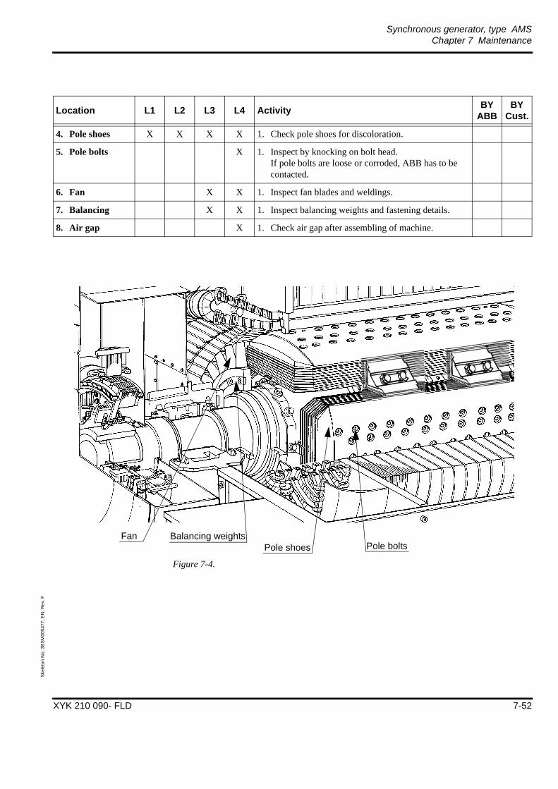
Synchronous generator, type AMSChapter 7 Maintenance
XYK 210 090- FLD 7-52
Skel
eton
No.
3B
SM00
5477
, EN
, Rev
. F
Figure 7-4.
Location L1 L2 L3 L4 Activity BY ABB
BY Cust.
4. Pole shoes X X X X 1. Check pole shoes for discoloration.
5. Pole bolts X 1. Inspect by knocking on bolt head. If pole bolts are loose or corroded, ABB has to be contacted.
6. Fan X X 1. Inspect fan blades and weldings.
7. Balancing X X 1. Inspect balancing weights and fastening details.
8. Air gap X 1. Check air gap after assembling of machine.
Balancing weightsPole shoes Pole bolts
Fan

Synchronous generator, type AMSChapter 7 Maintenance
XYK 210 090- FLD 7-53
Skel
eton
No.
3B
SM00
5477
, EN
, Rev
. F
7.3.5 BearingsLocation L1 L2 L3 L4 Activity Approved
1. Bearing inspection
X X 1. Open bearings.
2. Bearing housing and support
X X X X 1. Inspect for leaks.
X X X X 2. Inspect all bolted joints.
X X X X 3. Inspect guide support.
3. Shaft seals X X X X 1. Check for leaks. If leaks check wear and damages.
X X 2. Clean drain holes in the shaft seals.
3. Check the clearance between the shaft seals and shaft with a feeler gauge after assembling.
4. Shaft surface X X 1. Verify that sealing surface are free from corrosion and wearing.
5. Bearing liners X X 1. Visual inspection of contact surfaces.
6. Bearinginsulation
X X 1. Measure insulation resistance. Refer to Section 5.3 .
7. Oil piping X X X X 1. Inspect for leaks.
8. Measuring instrument
X X X X 1. Verify function of all measuring instrument.
9. Lube oil X X 1. Analyse oil for contamination and replace oil and clean the system if necessary. Refer to Section 7.5.3 .
2. Check for water in each bearing and remove if necessary.
10. Air filter X X X X 1. If necessary replace filter for air intake to the air-lock seals, located on bearing pedestals.

Synchronous generator, type AMSChapter 7 Maintenance
XYK 210 090- FLD 7-54
Skel
eton
No.
3B
SM00
5477
, EN
, Rev
. F
Figure 7-5.
Air-lock seals
Shaft seal
Bearing insulation
Bearing liners
Bearing shell
Bearing housing

Synchronous generator, type AMSChapter 7 Maintenance
XYK 210 090- FLD 7-55
Skel
eton
No.
3B
SM00
5477
, EN
, Rev
. F
7.3.6 PMG (Permanent magnetic generator)
WARNING - Magnetic force
There is a very strong magnetic forces between the PMG rotor and stator.
1. Be extremely careful when removing the PMG stator housing to avoid damage to components due to magnetic forces.
2. Remove your wrist watch, credit cards and other digital equipment before working around those magnetic forces.
3. Personnel with pace maker should not be working in the vicinity of the PMG..
Location L1 L2 L3 L4 Activity Approved
1. PMG Stator X X 1. Visual inspection.
X X X 2. Measure insulation resistance, 500V DC megger. Refer to Section 5.3 .
2. PMG Rotor X X 1. Visual inspection.
3. Air gap X X 1. Check air gap.

Synchronous generator, type AMSChapter 7 Maintenance
XYK 210 090- FLD 7-56
Skel
eton
No.
3B
SM00
5477
, EN
, Rev
. F
Figure 7-6.
PMG stator
PMG rotor
Permanent magnets
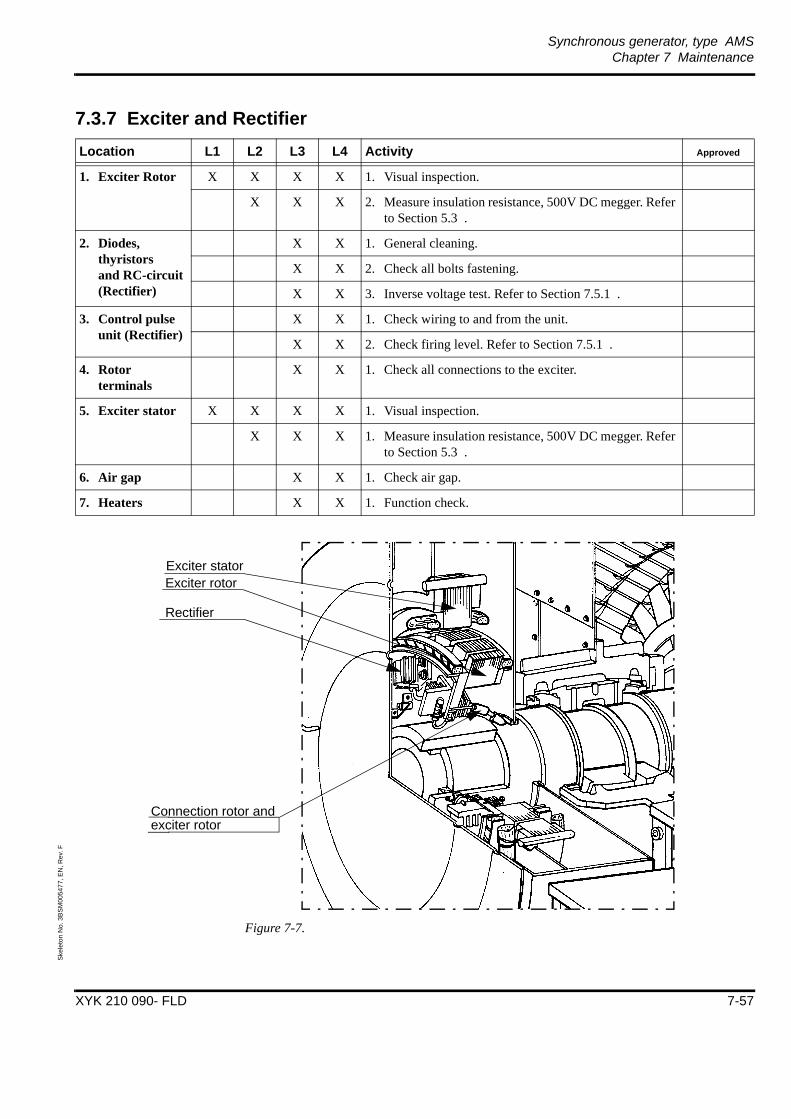
Synchronous generator, type AMSChapter 7 Maintenance
XYK 210 090- FLD 7-57
Skel
eton
No.
3B
SM00
5477
, EN
, Rev
. F
7.3.7 Exciter and Rectifier
Figure 7-7.
Location L1 L2 L3 L4 Activity Approved
1. Exciter Rotor X X X X 1. Visual inspection.
X X X 2. Measure insulation resistance, 500V DC megger. Refer to Section 5.3 .
2. Diodes, thyristors and RC-circuit(Rectifier)
X X 1. General cleaning.
X X 2. Check all bolts fastening.
X X 3. Inverse voltage test. Refer to Section 7.5.1 .
3. Control pulse unit (Rectifier)
X X 1. Check wiring to and from the unit.
X X 2. Check firing level. Refer to Section 7.5.1 .
4. Rotor terminals
X X 1. Check all connections to the exciter.
5. Exciter stator X X X X 1. Visual inspection.
X X X 1. Measure insulation resistance, 500V DC megger. Refer to Section 5.3 .
6. Air gap X X 1. Check air gap.
7. Heaters X X 1. Function check.
Exciter statorExciter rotor
Rectifier
Connection rotor andexciter rotor
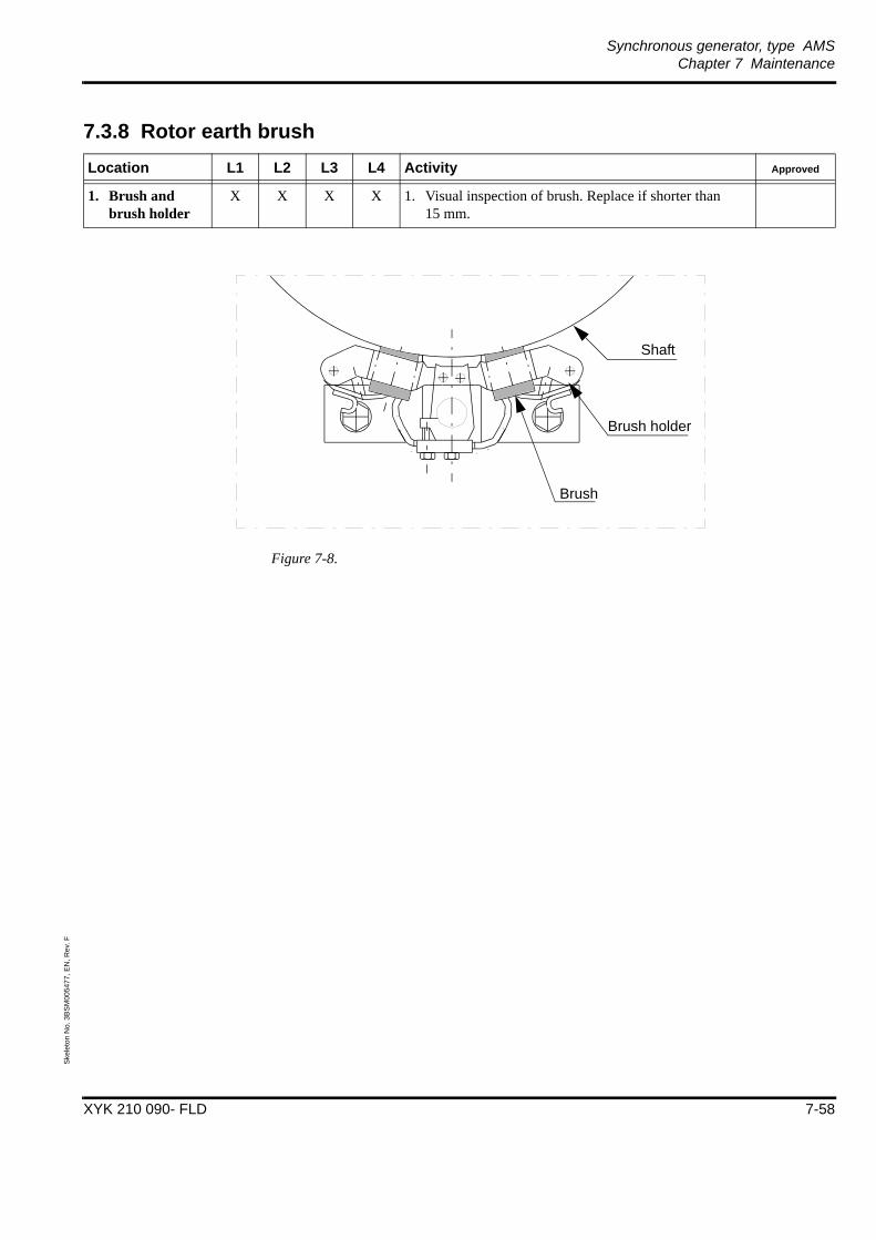
Synchronous generator, type AMSChapter 7 Maintenance
XYK 210 090- FLD 7-58
Skel
eton
No.
3B
SM00
5477
, EN
, Rev
. F
7.3.8 Rotor earth brush
Figure 7-8.
Location L1 L2 L3 L4 Activity Approved
1. Brush and brush holder
X X X X 1. Visual inspection of brush. Replace if shorter than 15 mm.
+
+
+
+ +
++
+
+
Brush
Brush holder
Shaft

Synchronous generator, type AMSChapter 7 Maintenance
XYK 210 090- FLD 7-59
Skel
eton
No.
3B
SM00
5477
, EN
, Rev
. F
7.3.9 Cooling system
*) If bad efficiency clean the heatexchanger by using brush or chemical rinsing.
Figure 7-9.
Location L1 L2 L3 L4 Activity Approved
1. Coolers
Refer to instruction in included in the binder “Users manual”.
X X X X 1. Visual inspection.
X*) X*) X X 2. Check for cleanliness, corrosion and erosion of air and water sides.
X*) X*) X X 3. Clean air and water sides.
X X 4. Inspect protection anodes (placed in tube sheet) for proper activity and replace if necessary.
X*) X*) X X 5. Pressure test.
X X X X 6. Function check of casing water leakage detector.
Tube
Tube plate
Gasket
Water box
Actual design acc. to outline included in binder “Users Manual”

Synchronous generator, type AMSChapter 7 Maintenance
XYK 210 090- FLD 7-60
Skel
eton
No.
3B
SM00
5477
, EN
, Rev
. F
If temperature detectors show normal temperature, usually no additional maintenance to supervision inspection is required for the cooling system. If the coolers have to be cleaned, find instruction included in binder “Users Manual”.
If temperature detectors show an abnormal temperature, or close to alarm level, in winding or cooling air a check of the cooling system has to be made. If the coolers have to be cleaned, find instructions included in binder “Users Manual”.
Water leakage detector
To empty the water leakage detector of water, open the ball valve at the bottom of leakage detector, see drawing included in the binder “User Manual”.Figure 7-10
7.4 Main rotor coil turn insulation (voltage drop test)
WARNING - Electricity 230 V or 400 V 50 Hz / 208 V or 480 V 60 Hz
During the voltage drop test there is a AC-voltage over the field windings. Be careful so no personal injury occur.
1. Connect all measuring cables before start of measurement.
2. Connect a earth current circuit breaker as protection.
The test is carried out by applying an AC-voltage over the entire field winding and measuring the current and the voltage drop across the total winding as well as each single coil, see Figure 7-11.
The applied voltage should be 230 V or 400 V 50 Hz / 208 or 480 V 60 Hz depending on the rated frequency of the machine.
Figure 7-11
7.5 Fault findingThe generator is protected with alarms and trips for most kinds of abnormal running conditions, both electrical and mechanical. Some of these protections can be reset and the generator restarted directly as the fault is known or easy to locate.
+
-
U
ΔU1
ΔU2
ΔU3ΔU4
The voltage over a single coil (ΔU) should not differ more than ±3% from U/4.

Synchronous generator, type AMSChapter 7 Maintenance
XYK 210 090- FLD 7-61
Skel
eton
No.
3B
SM00
5477
, EN
, Rev
. F
Examples of protections that if they give an alarm or trip, may need further investigations to be located are:
• Diode fault protection.
• High temperature in bearing.
• High temperature in winding or in cooling air.
• Vibration protection.
7.5.1 Diode faultIn case any of the diodes in the rotating rectifier should fail, the “diode fault” protection will pick up and trip the generator. To determine and locate a faulty diode, open the cover of the rotating rectifier and megger with an ohm-meter over one of the diodes. If a faulty diode is detected, disconnect all diodes and test them separately to locate the faulty diode.
NOTE: If a faulty diode or thyristor the recommendation is to replace all diodes, thyristors and control pulse unit.
Refer to the instruction “Replacement of diodes and thyristors” included in the binder “Users Manual”.
To test the thyristors, firing unit and diodes the following method can be used:
• Open the cover of the rotating rectifier.
• Disconnect the rotor winding from the rectifier.
• Apply alternating voltage to the plus and minus bars of the diode bridge according to figure 7-12. A 600 ohm resistor shall be connected to limit the current flow as shown in figure 7-12.
Note: An equipment specially made for this test is possible to buy from ABB AB, Machines.
Figure 7-12
• Increase the voltage and check with an oscilloscope the triggering voltage level of the firing unit and the thyristors as shown in figure 7-13 chart 2 and 3.
• Decrease the voltage to a level under the firing units trigger level, see figure 7-13 chart 1 and measure over each diode separately. A shorted diode will show zero (0) volt on the oscilloscope.
osc
≈ 600 Ω
Test equipment Rectifier unit
Exciterside
-
+
voltageSupply
Uac
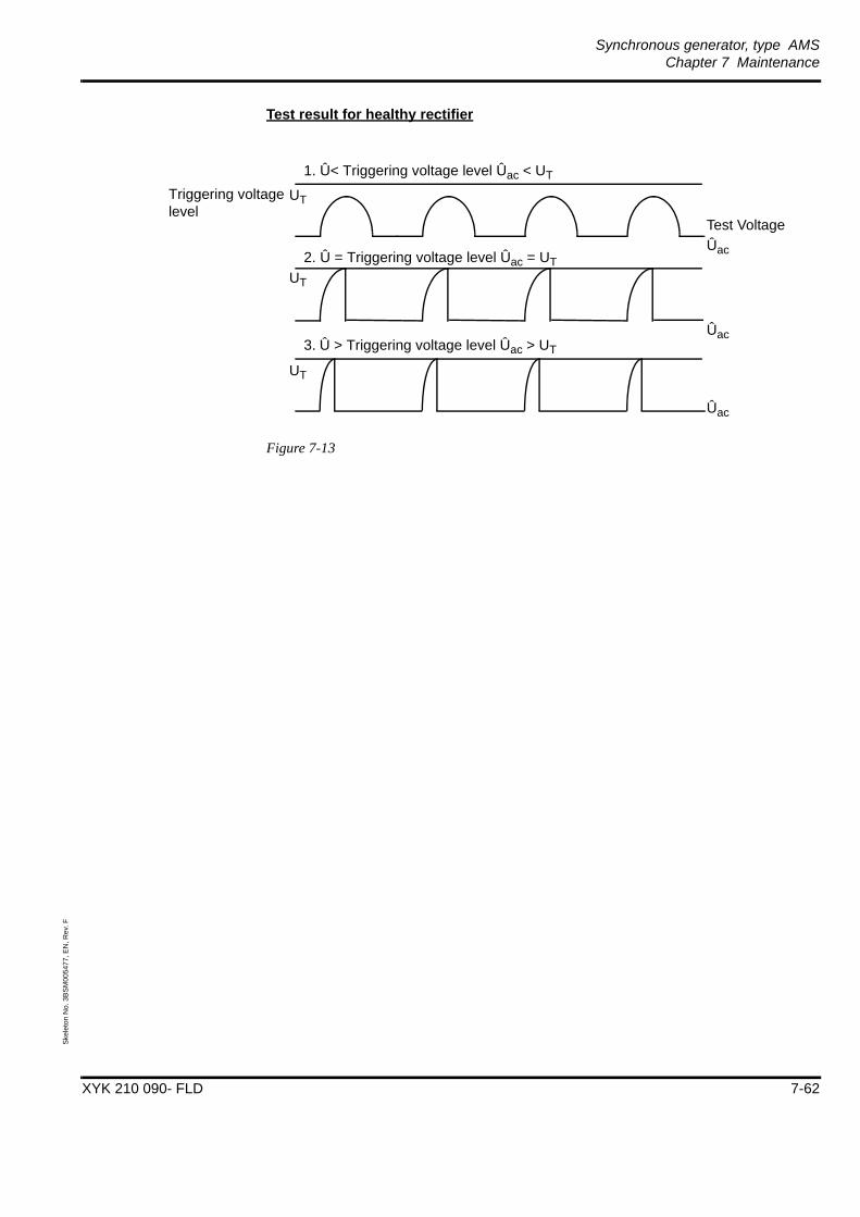
Synchronous generator, type AMSChapter 7 Maintenance
XYK 210 090- FLD 7-62
Skel
eton
No.
3B
SM00
5477
, EN
, Rev
. F
Test result for healthy rectifier
Figure 7-13
1. Û< Triggering voltage level Ûac < UT
2. Û = Triggering voltage level Ûac = UT
3. Û > Triggering voltage level Ûac > UT
Triggering voltagelevel
UT
Ûac
Ûac
Ûac
UT
UT
Test Voltage
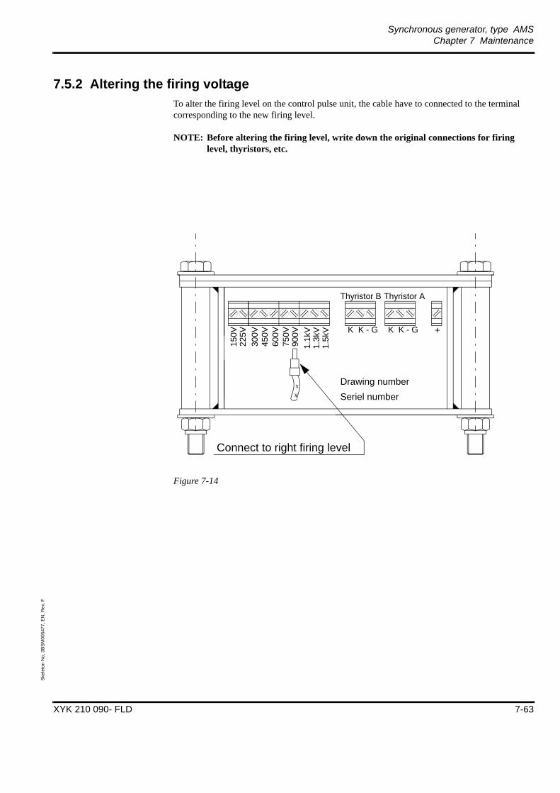
Synchronous generator, type AMSChapter 7 Maintenance
XYK 210 090- FLD 7-63
Skel
eton
No.
3B
SM00
5477
, EN
, Rev
. F
7.5.2 Altering the firing voltageTo alter the firing level on the control pulse unit, the cable have to connected to the terminal corresponding to the new firing level.
NOTE: Before altering the firing level, write down the original connections for firing level, thyristors, etc.
Figure 7-14
x
x Drawing number Seriel number
150V
225V
300V
450V
600V
750V
900V
1.1k
V1.
3kV
1.5k
V
Thyristor AThyristor B
K K - G K K - G +
Connect to right firing level

Synchronous generator, type AMSChapter 7 Maintenance
XYK 210 090- FLD 7-64
Skel
eton
No.
3B
SM00
5477
, EN
, Rev
. F
7.5.3 LubricationThe generators are provided with sleeve bearings with an almost unlimited service life provided that the lubrication functions continuously and that the oil is changed at suitable intervals.
Temperature
To enable the bearing temperature to stabilize at a normal level, the correct amount or flow of oil is required. The normal bearing temperature is 65 - 85 oC.
NOTE: The oil may be warm.
Characteristic properties of the oil qualities listed are:
The oil is a lubricant based on paraffin having high viscosity coefficient (VI>90) and a particularly low fluid temperature. It includes the following additives:
• oxidation inhibitor
• anti-foaming
• mild EP action, anti-wear additive
• rust inhibitor
Condition of the lubricant
Check the oil with respect to colour, smell, turbidity and deposits in a test bottle.
The following requirements shall be fulfilled:
• The oil should be clear or negligibly turbid. The turbidity may not be caused by water.
• Strong acid or burnt smell is not acceptable.
• The quantity of metal impurities may not exceed 0.05% by weight.
• The original viscosity must be maintained within a tolerance of ±10-15%.
• The original acid number should not be exceeded by more than 1 mg KOH per gram oil.
An oil check should be performed a few days after the first test run of the generator and subsequently as required. If the oil is changed just after the commissioning, it can be used again after removing wear particles by filtering or centrifuging.
In doubtful cases an oil sample may be sent to the laboratory to determine viscosity, acid number, foaming tendency, etc.
A duty period of 3-8 years before an oil change is necessary is not unusual.

Synchronous generator, type AMSChapter 7 Maintenance
XYK 210 090- FLD 7-65
Skel
eton
No.
3B
SM00
5477
, EN
, Rev
. F
Oil qualities
Unless otherwise stated on ABB AB, Machines drawing “Outline synchronous generator” included in the binder “Users Manual”, the bearings are designed for any of the following oil qualities:
Oil 7 1201-301 (Oil 7061)ISO VG 32
Viscosity 32 cSt at 40°C (20 at 50°C)Pour point max. -30°C.
BP: Energol HLP 32Castrol: Hyspin AWS 32Esso: Nuto HP 32Gulf: Harmony 32 AWKlüber: Lamora 32Mobil: D. T. E. 24Optimol: Ultra 5025Shell: Tellus Oil 32Texaco: Rando Oil HD A 32
Oil 7 1201-302 (Oil 7071)ISO VG 46
Viscosity 46 cSt at 40°C (28 at 50°C)Pour point max. -30°C.
BP: Energol HLP 46Castrol: Hyspin AWS 46Esso: Nuto HP 46Gulf: Harmony 46 AWKlüber: Lamora 46Mobil: D. T. E. 25Optimol: Ultra 5035Shell: Tellus Oil 46Texaco: Rando Oil HD B 46
Oil 7 1201-303 (Oil 7081)ISO VG 68
Viscosity 68 cSt at 40°C (40 at 50°C)Pour point max. -27°C.
BP: Energol HLP 68Castrol: Hyspin AWS 68Esso: Nuto HP 68Gulf: Harmony 68 AWKlüber: Lamora 68Mobil: D. T. E. 26Optimol: Ultra 5045Shell: Tellus Oil 68Texaco: Rando Oil HD C 68
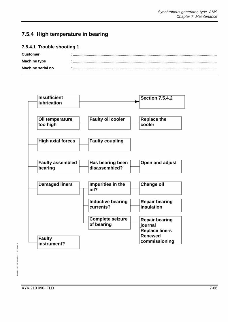
Synchronous generator, type AMSChapter 7 Maintenance
XYK 210 090- FLD 7-66
Skel
eton
No.
3B
SM00
5477
, EN
, Rev
. F
7.5.4 High temperature in bearing
7.5.4.1 Trouble shooting 1Customer : .......................................................................................................................................
Machine type : .......................................................................................................................................
Machine serial no : .......................................................................................................................................
Insufficient lubrication
Faulty instrument?
Damaged liners
Faulty assembled bearing
High axial forces
Oil temperature too high
Faulty oil cooler Replace the cooler
Faulty coupling
Has bearing been disassembled?
Impurities in the oil?
Inductive bearing currents?
Complete seizure of bearing
Open and adjust
Change oil
Repair bearing insulation
Repair bearing journal Replace linersRenewed commissioning
Section 7.5.4.2
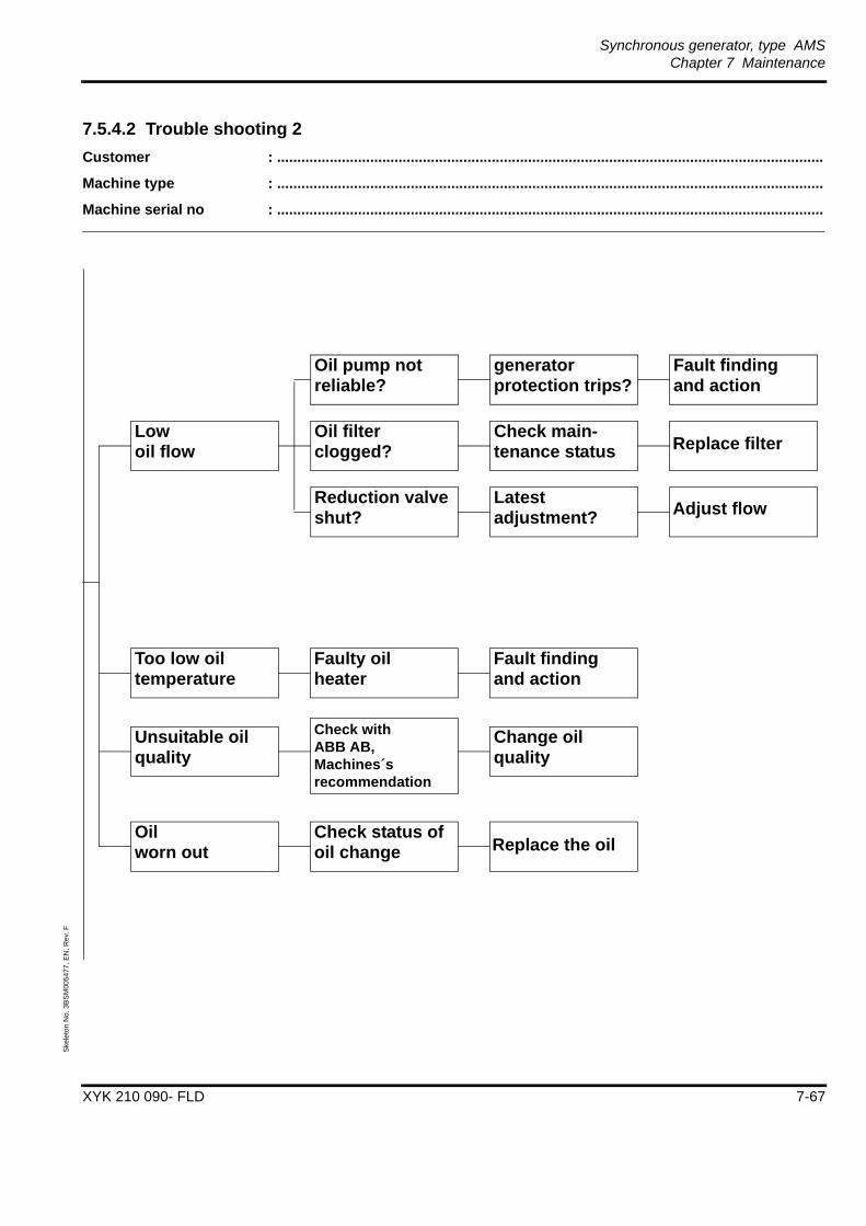
Synchronous generator, type AMSChapter 7 Maintenance
XYK 210 090- FLD 7-67
Skel
eton
No.
3B
SM00
5477
, EN
, Rev
. F
7.5.4.2 Trouble shooting 2Customer : .......................................................................................................................................
Machine type : .......................................................................................................................................
Machine serial no : .......................................................................................................................................
Low oil flow
Too low oil temperature
Unsuitable oil quality
Oil worn out
Reduction valve shut?
Oil filter clogged?
Oil pump not reliable?
Check status of oil change
Change oil quality
Check with ABB AB, Machines´s recommendation
Fault finding and action
Faulty oilheater
generator protection trips?
Check main-tenance status
Latest adjustment?
Fault finding and action
Replace filter
Adjust flow
Replace the oil

Synchronous generator, type AMSChapter 7 Maintenance
XYK 210 090- FLD 7-68
Skel
eton
No.
3B
SM00
5477
, EN
, Rev
. F
7.5.4.3 Trouble shooting 3Customer : .......................................................................................................................................
Machine type : .......................................................................................................................................
Machine serial no : .......................................................................................................................................
Unstable bearing temperature
Impurities in the oil Replace the oil
Oil worn out Replace the oil
Oil leaks
Problem in oil flow return
Too high oil flow Correct oil flow
Incorrect inclination of the return pipe?
Damaged shaft seals
Air-lock seal out of action
Repair the seals
Repair/replace the air-lock seal and check the air filters

Synchronous generator, type AMSChapter 7 Maintenance
XYK 210 090- FLD 7-69
Skel
eton
No.
3B
SM00
5477
, EN
, Rev
. F
7.5.5 High winding and/or air temperature
7.5.5.1 Trouble shootingCustomer : .......................................................................................................................................
Machine type : .......................................................................................................................................
Machine serial no :.......................................................................................................................................
High winding and/or air temperature
Dirty or plugged cooler
Cooling water temperature to high
Clean the cooler
Faulty instrument
Low cooling water flow
Faulty sensor
Leaking cooler
Air inside the cooler
Replace the cooler
Bleed the cooler
Overload
Dirty stator
Process control
Clean the stator

Synchronous generator, type AMSChapter 8 Disposal and Recycling
XYK 210 090- FLD 8-70
Skel
eton
No.
3B
SM00
5478
, EN
, Rev
. E
Chapter 8 Disposal and Recycling
8.1 GeneralThe manufacturing process of the machine is carried out in accordance with the Environmental Management System ISO 14001.
This instruction concerns the disposal and recycling of Large AC-machines. The machines are designed in a way that it is easy to separate the different components and types of material from eachother, making it esier to recycle.
NOTE: The methods are described in a very general way. All instructions are to be performed by personnel which is trained and skilled for the procedure.
8.2 Dismantling the machine
Warning - Heavy components
Risk of personal injury when dismantling the machine.
1. Only skilled and trained personnel should carry out the dismantling.
Dismantling the machine is done by simply separating all the components of the machine. Since the machine mainly is assembled with screws and nuts, it is rather simple to carry out the dismantling. When the machine has been dismantled into its different components, the different components has to be separated and grouped together dependent upon the different types of material.
8.3 Separation of different types of material8.3.1 Normal carbon steel
The following components is separated into one group for normal carbon steel:• Rotor body• Stator ends• Bearing supports• Foot plates• Encapsulation• Side plates• Roof• Oil tubes from the lubrication system.
If the tubes are made of stainless steal, it is necessary to separate them from the rest of the steel components. If not the stainless steel will cause a very low quality of the total steel collected - it is a poison for the steel manufacturer.
• Teminal box with the copper separated• Bolts and nuts• etc ... etc.
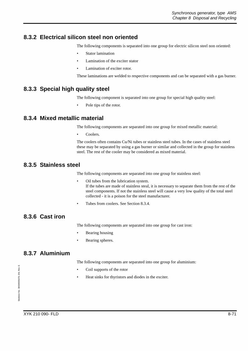
Synchronous generator, type AMSChapter 8 Disposal and Recycling
XYK 210 090- FLD 8-71
Skel
eton
No.
3B
SM00
5478
, EN
, Rev
. E
8.3.2 Electrical silicon steel non orientedThe following components is separated into one group for electric silicon steel non oriented:
• Stator lamination
• Lamination of the exciter stator
• Lamination of exciter rotor.
These laminations are welded to respective components and can be separated with a gas burner.
8.3.3 Special high quality steelThe following component is separated into one group for special high quality steel:
• Pole tips of the rotor.
8.3.4 Mixed metallic materialThe following components are separated into one group for mixed metallic material:
• Coolers.
The coolers often contains Cu/Ni tubes or stainless steel tubes. In the cases of stainless steel these may be separated by using a gas burner or similar and collected in the group for stainless steel. The rest of the cooler may be considered as mixed material.
8.3.5 Stainless steelThe following components are separated into one group for stainless steel:
• Oil tubes from the lubrication system.If the tubes are made of stainless steal, it is necessary to separate them from the rest of the steel components. If not the stainless steel will cause a very low quality of the total steel collected - it is a poison for the steel manufacturer.
• Tubes from coolers. See Section 8.3.4.
8.3.6 Cast ironThe following components are separated into one group for cast iron:
• Bearing housing
• Bearing spheres.
8.3.7 AluminiumThe following components are separated into one group for aluminium:
• Coil supports of the rotor
• Heat sinks for thyristors and diodes in the exciter.
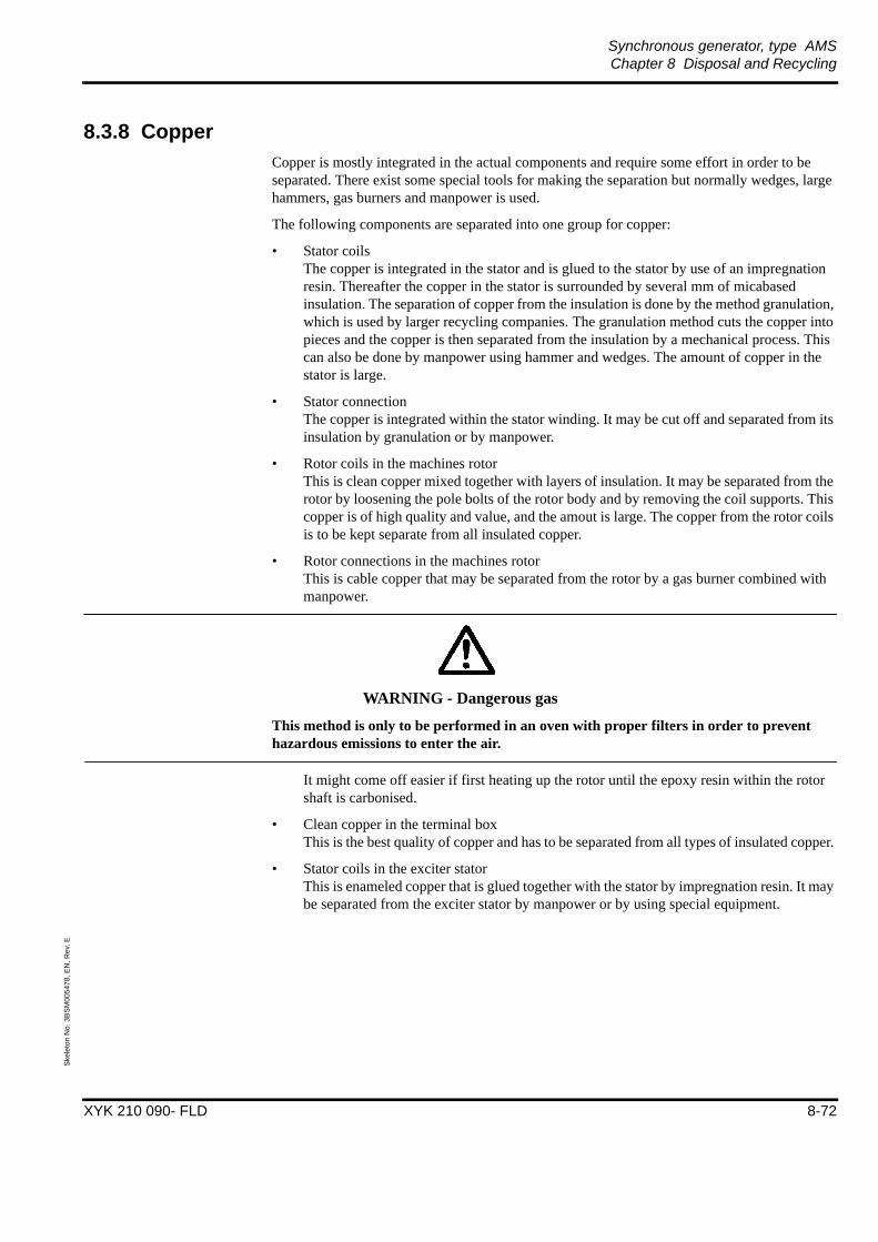
Synchronous generator, type AMSChapter 8 Disposal and Recycling
XYK 210 090- FLD 8-72
Skel
eton
No.
3B
SM00
5478
, EN
, Rev
. E
8.3.8 CopperCopper is mostly integrated in the actual components and require some effort in order to be separated. There exist some special tools for making the separation but normally wedges, large hammers, gas burners and manpower is used.
The following components are separated into one group for copper:
• Stator coilsThe copper is integrated in the stator and is glued to the stator by use of an impregnation resin. Thereafter the copper in the stator is surrounded by several mm of micabased insulation. The separation of copper from the insulation is done by the method granulation, which is used by larger recycling companies. The granulation method cuts the copper into pieces and the copper is then separated from the insulation by a mechanical process. This can also be done by manpower using hammer and wedges. The amount of copper in the stator is large.
• Stator connectionThe copper is integrated within the stator winding. It may be cut off and separated from its insulation by granulation or by manpower.
• Rotor coils in the machines rotorThis is clean copper mixed together with layers of insulation. It may be separated from the rotor by loosening the pole bolts of the rotor body and by removing the coil supports. This copper is of high quality and value, and the amout is large. The copper from the rotor coils is to be kept separate from all insulated copper.
• Rotor connections in the machines rotorThis is cable copper that may be separated from the rotor by a gas burner combined with manpower.
WARNING - Dangerous gas
This method is only to be performed in an oven with proper filters in order to prevent hazardous emissions to enter the air.
It might come off easier if first heating up the rotor until the epoxy resin within the rotor shaft is carbonised.
• Clean copper in the terminal boxThis is the best quality of copper and has to be separated from all types of insulated copper.
• Stator coils in the exciter statorThis is enameled copper that is glued together with the stator by impregnation resin. It may be separated from the exciter stator by manpower or by using special equipment.

Synchronous generator, type AMSChapter 8 Disposal and Recycling
XYK 210 090- FLD 8-73
Skel
eton
No.
3B
SM00
5478
, EN
, Rev
. E
WARNING - Dangerous gas
This metod is only to be performed in an oven with proper filters in order to prevent hazardous emissions to enter the air.
It might come of easier if first heating up the stator until the impregnation resin is carbonized.
• Rotor coils in the exciter rotorThis is enammelded copper that is glued together by impregnation resin. It may be separated from the exciter by manpower or using special equipment.
WARNING - Dangerous gas
This metod is only to be performed in an oven with proper filters in order to prevent hazardous emissions to enter the air.
It might come of easier if first heating up the rotor until the impregnation resin is carbonised.
8.4 Waste as land fillAll inslulation material is not to be considered as hazardous waste. It may be used as land fill or sent to power plants to be burned.
NOTE: Make sure the power plant is adapted for this kind of fuel and have the proper types of filter etc. in order to prevent gases and dust to enter the environment.
8.5 Hazardous wasteThe oil from the lubrication system is to be considered as hazardous waste and have to be taken care of according to regulations. The oil is to be sent for destruction or to be burned in specially prepared power plants.
8.6 Final commentsIf there is some questions of enviromental matters not considered in this instruction we ask the user to get in contact with the Environmental Coordinator of the Machine Division.

XYK 210 090- FLD2001-02-22
Skeleton N
o. 3BSM
005468, Rev. G
EN


We reserve all rights in this document and in the information contained therein. Reproduction,use or disclosure to third parties without express authority is strictly forbidden.ABB Automation Technologies AB; 2003
External doc. no.
Based on 3BSM001263R0001 en Project
Prep. MO / A. Kruse 1997-04-21 Customer
Appr. / Engelen Christina Approved Proj. no.
Doc. kind Description Doc. des.
Ref. des.
Title Assembly Instruction, current-carrying busbars Resp. dept MO
Doc. no. Lang. Rev. ind. Page 1ABB Automation Technologies AB 3BSM001263R0001 en B No. of p. 5
FILE: Assembly Instruction current-carrying busbars.doc; TEMPLATE: Techn_Doc_Deliv_P.dot B; SKELETON: ; SAVEDATE: 2005-01-20 10:33:00 AM
Bolted joints for current-carrying busbars.
Instructions pertaining to assembly.
1. ForewordThis document contains general instructions regarding the procedure to be adopted when making bolted joints in busbars.
For series-manufactured switchgear, apparatus etc., special assembly instructions are normally provided and these apply to the complete installation including the bolted joints in busbars.
For joints in other equipment, where special measures must be taken, e.g. control of tightening torque, special locking facilities etc., instructions are either given on the assembly drawing or are supplied separately for the joints in question.
If modifications are necessary during the on-site installation work, it is of the utmost importance that the joints are made in accordance with the applicable standard to ensure satisfactory performance.
2. Preparation of contact surfaces
2.1 Cleaning
Dirt, oil and grease are to be removed with white spirits or other suitable degreasing agent.
Paints, insulating varnishes, resin residues etc., are to be removed with a steel-wire brush or by scraping with a keen-edged tool.
Surface-treated busbars (tinned, nickel plated, silver plated) must not be subjected to mechanical cleaning. Great care must be exercised when cleaning EXCONAL busbars to avoid damaging the copper layer.
2.2 Deburring
Burrs and mechanical defects are to be removed with the aid of suitable keen-edged tools. When removing burrs from holes in EXCONAL busbars, the edges should not be chamfered more than necessary. Mechanical grinding, especially of EXCONAL busbars, should be avoided. Care must be taken to ensure that the flatness and the texture of the surfaces are not influenced in any way.

Doc. kind Description Project
CustomerTitle Assembly Instruction, current-carrying busbars Proj. no.
Doc. no. Lang. Rev. ind. Page 2ABB Automation Technologies AB 3BSM001263R0001 en B No. of p. 5
2.3 Measures to prevent oxidation and corrosion
Depending on the type of busbars material and the environment in which the bars are to be installed, the contact surfaces are to be prepared as specified in the following table:
Material
Environment
Copper, copper-clad aluminium, tinned, silver or nickel plated bars/surfaces
Aluminium, both pure and alloyed, the aluminium surfaces in joints aluminium-copper
Indoors, dry places, in oil.
No measures necessary.
Surfaces of the joint to be roughened with a wire brush or a rough file and cleaned from sward and oxide particles.Immediately (within 5 minutes), the surfaces are to be coated with petrolatum (vaseline) 1171 5011-102 and the joint fitted together.
Outdoors, damp or corrosive atmospheres.
The contact surfaces are to be coated with petrolatum (vaseline) 1171 5011-102.
As above. On joints of aluminiumcopper in severe corrosive atmospheres, use either Cu-Al-strip or paint as per 2965 2273.
Table 1
If the customer or other authorities require that a paste, other than that mentioned above, is to be used, the directions for use must be carefully followed.
3. Bolted jointsThe design of the joint is shown in Figure 1.
Note The plane washer need to be mounted nearest the bar, according to Figure 1.

Doc. kind Description Project
CustomerTitle Assembly Instruction, current-carrying busbars Proj. no.
Doc. no. Lang. Rev. ind. Page 3ABB Automation Technologies AB 3BSM001263R0001 en B No. of p. 5
It is essential that the correct types of plane and spring tension washer are used (refer to the applicable standard pertaining to bolted joints), and that the spring tension washers are correctly positioned, i.e., the outer edge of the washer mates against the busbar or the plane washer.
Plane washerSpring tension washer
Figure 1
3.1 Tightening of bolts and nuts
Nuts should be tightened to the same extent as those used in bolted joints of steel structures. Endeavours should be made to achieve a tightening torque which, as near as possible, corresponds to that specified for each respective bolt. The tightening torque for bolts of strength class 8.8 is given in Table 2.
As a rule, a torque wrench is not necessary unless it is stipulated on the assembly drawings or in special assembly instructions. The type of wrench used should be such as to enable the easy application of the correct torque.
The nuts should not be turned in the anti-clockwise direction after they have been tightened.
3.2 Tightening torque and leverage
The tightening torque for dry or lightly oiled bolts of strength class 8.8 is given in Table 2.
The maximum force which a person can normally exert with one arm lies between 250 and 500N (newtons), corresponding to the force required to lift a weight of between 25 and 50 kg. For M8 and smaller bolts, a maximum force need not normally be applied.

Doc. kind Description Project
CustomerTitle Assembly Instruction, current-carrying busbars Proj. no.
Doc. no. Lang. Rev. ind. Page 4ABB Automation Technologies AB 3BSM001263R0001 en B No. of p. 5
To provide some idea of the amount of leverage required, i.e. the distance from the centre of the bolt to the middle of the hand used for applying the force, for larger sizes of bolt, the requisite leverage for an applied force of 300N and for achieving the requisite torque, is given in Table 2.
Bolt Tightening torque Leverage distance
M Nm kgfm lbf x ft m
6 10 1 7,4
8 18-25 1,8-2,5 13-19
10 35-50 3,5-5 26-37 0,12-0,17
12 60-85 6-8,5 45-63 0,21-0,28
16 150-200 15-20 110-150 0,5-0,67
20 330-430 33-43 240-320 1,1-1,4
Table 2

Doc. kind Description Project
CustomerTitle Assembly Instruction, current-carrying busbars Proj. no.
Doc. no. Lang. Rev. ind. Page 5ABB Automation Technologies AB 3BSM001263R0001 en B No. of p. 5
REVISION
Rev. Description Date, Resp.
A
B
Change of template.
Changed org. name to ABB Automation Technologies AB.
03-01-08MVO/PP
04-06-22 MVO/MK
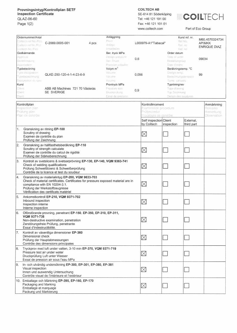

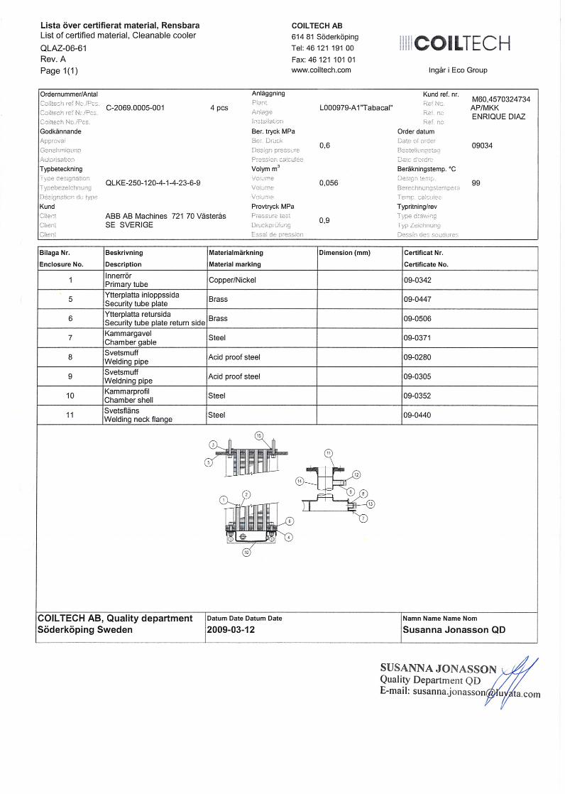
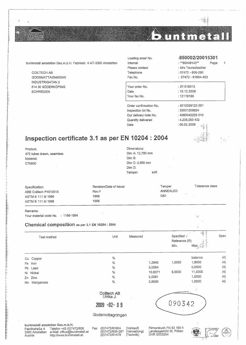


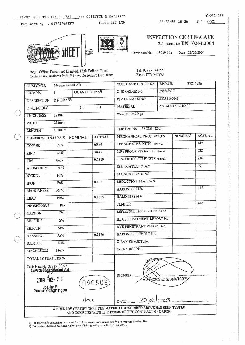
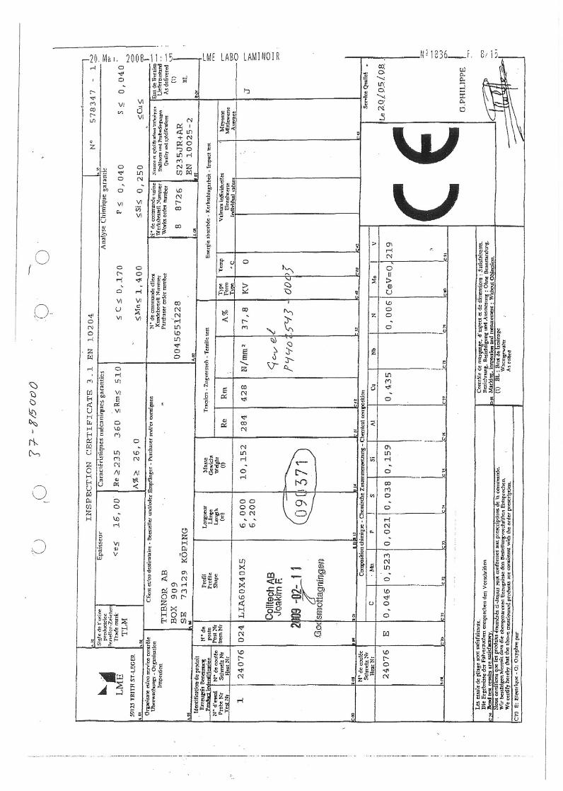

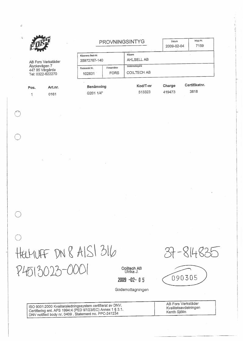
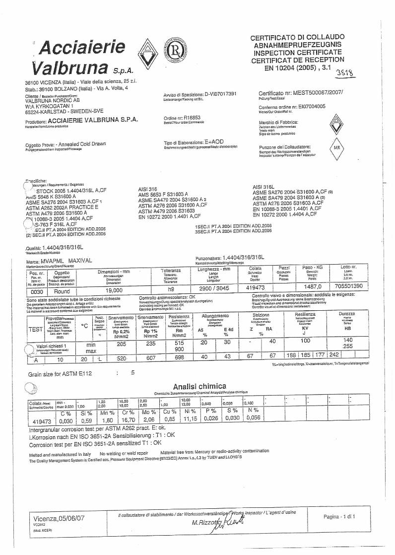
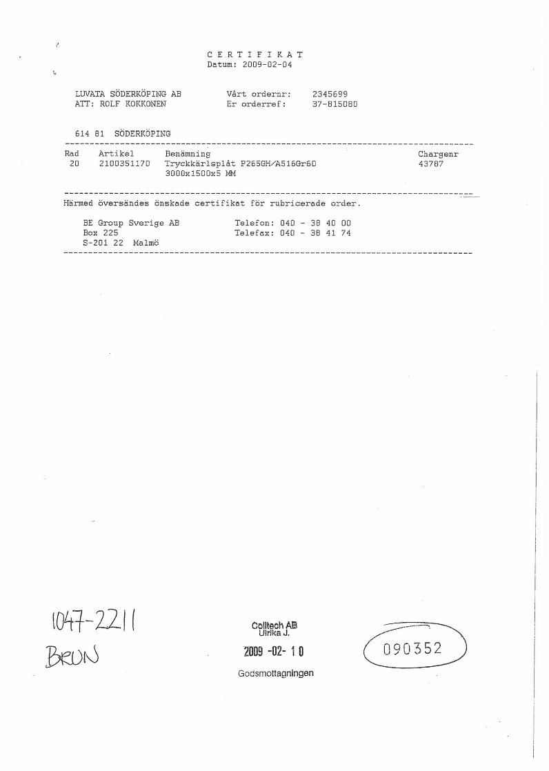
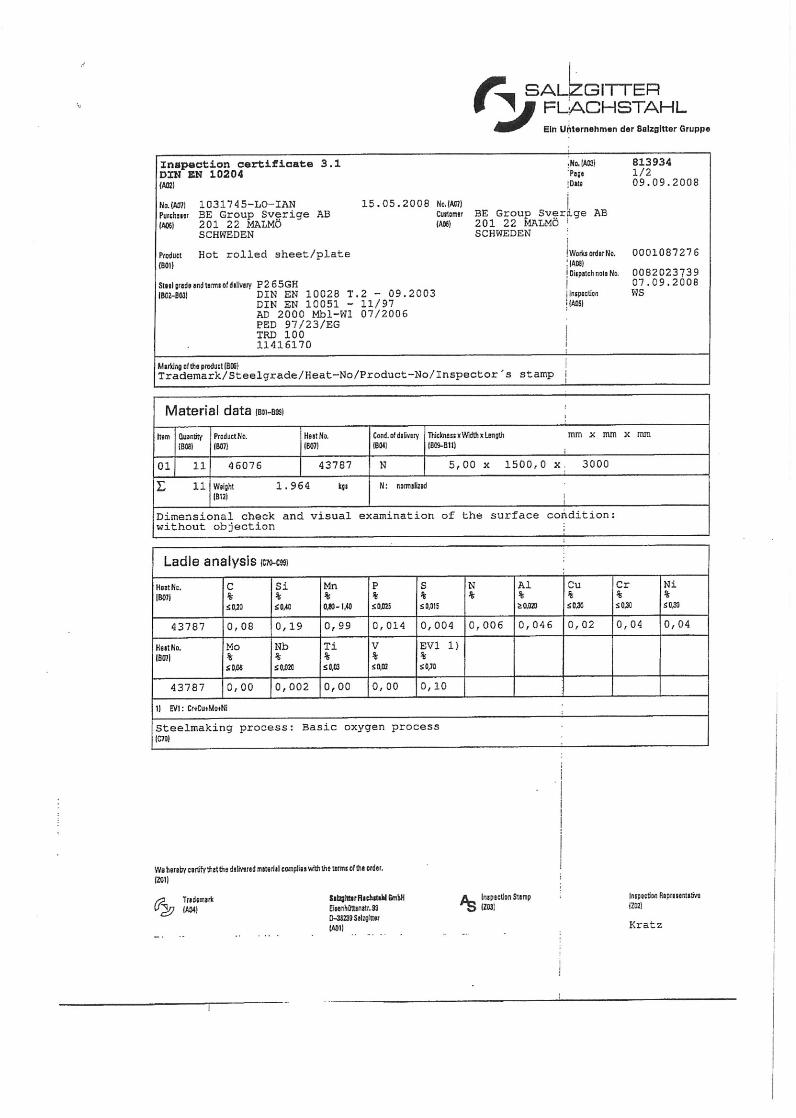

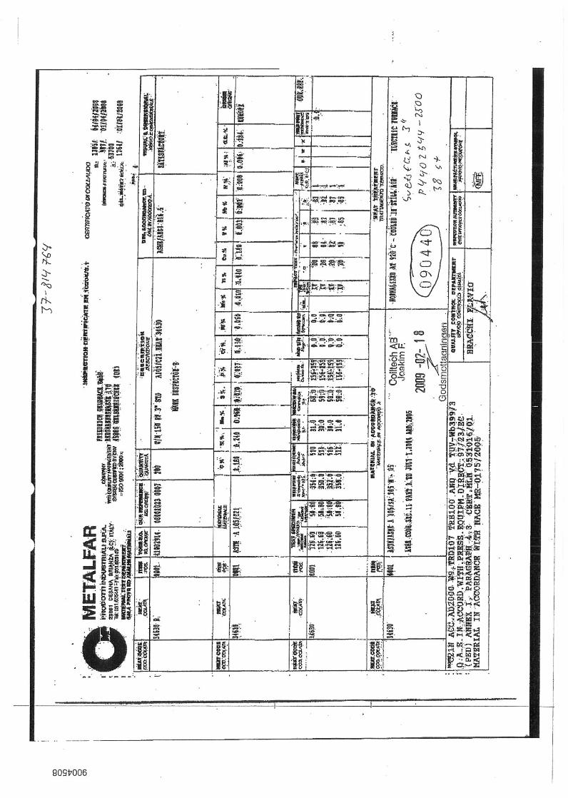
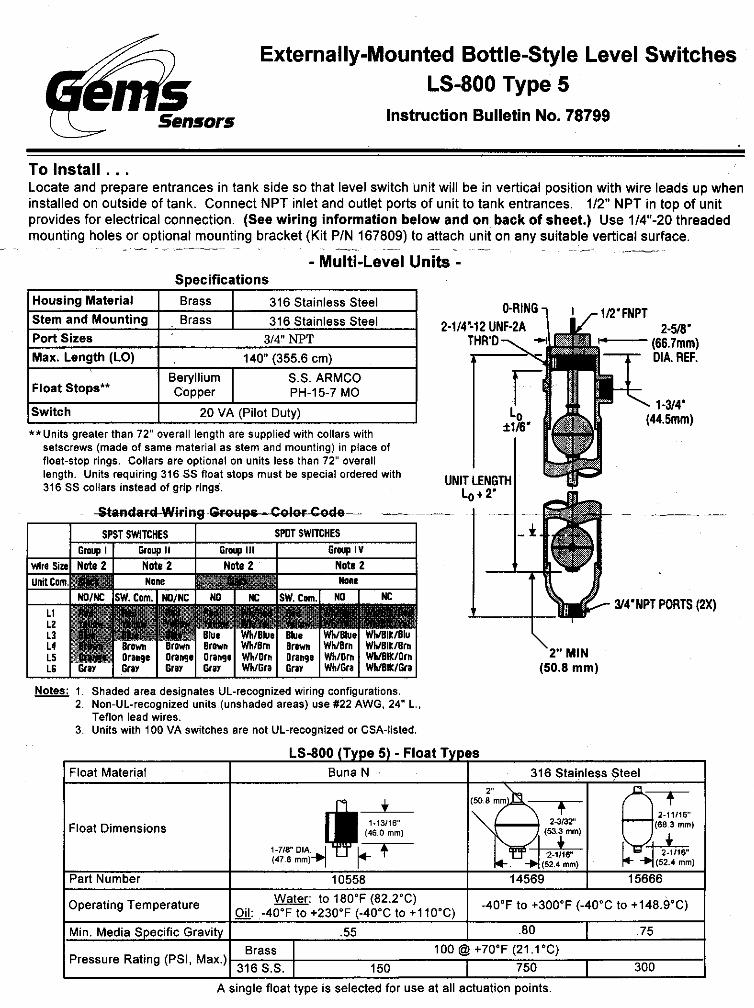

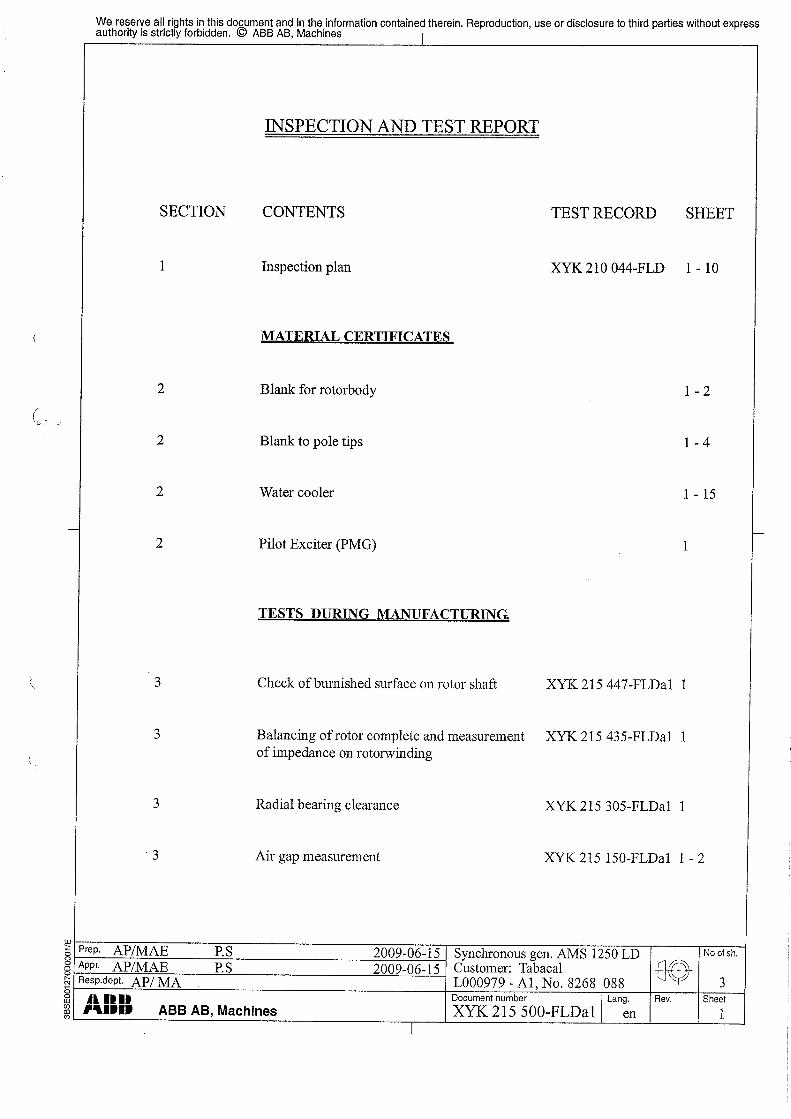


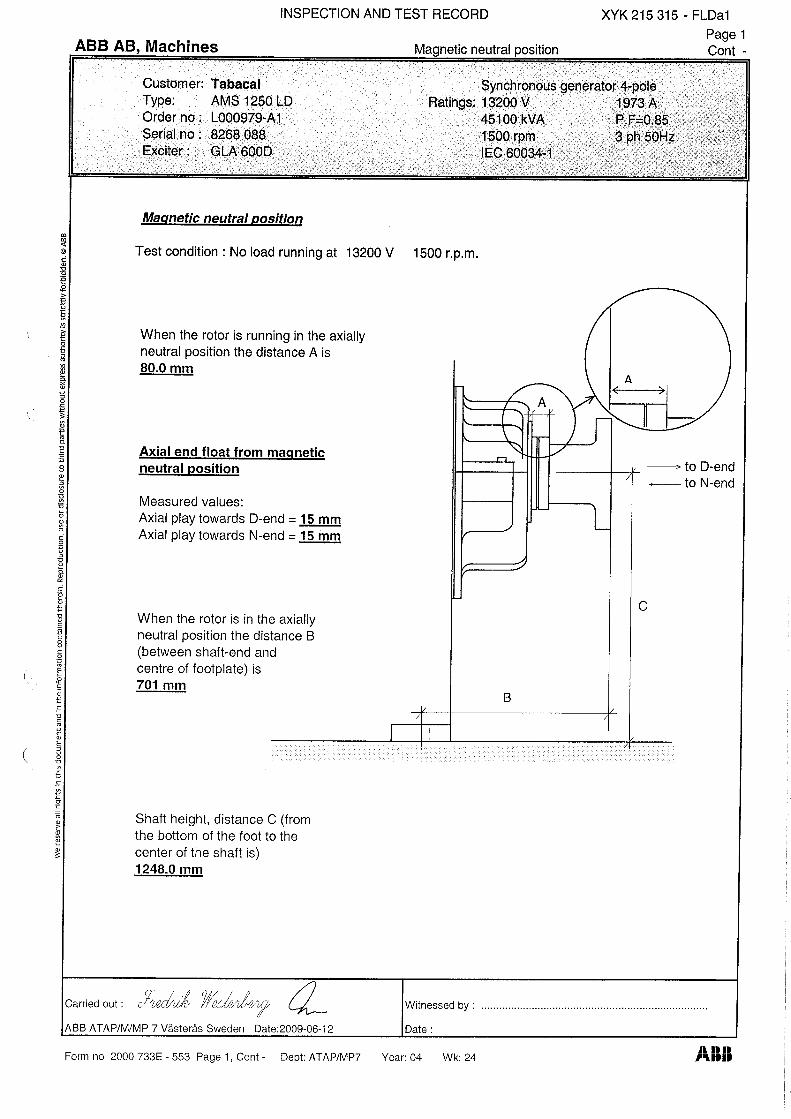

QLKEQLKEQLKEQLKE, QDKE, QDKE, QDKE, QDKE and QDKR Cleanable Air Coolers and QDKR Cleanable Air Coolers and QDKR Cleanable Air Coolers and QDKR Cleanable Air Coolers
Installation, Operation and Maintenance Instruction
Coiltech 2(4) Specifications are subject to alteration without notice R 1 019 145-0002D
Description Description Description Description –––– Safety Precautions and Warnings Safety Precautions and Warnings Safety Precautions and Warnings Safety Precautions and Warnings
General The cooler is used for the cooling of air by means of circulating water. The cooler is equipped with removable headers that allow cleaning inside the cooler.
Labelling The cooler data plate is located on the connection side of the cooler and indicates the following: Manufacturer. Max. working pressure. Test pressure. Order number. Year of manufacture. Dry weight. Internal liquid volume.
Quality System
Coiltech AB has a certified Quality Assurance System to ISO 9001 and a Certified Environmental Management System to ISO 14001.
Handling and Maintenance Read all the maintenance instructions before you begin handling this product. The cooler should be installed where it is accessible for cleaning, but not where the general public has access to it. Only let trained personel with profound knowledge of the product and the appropriate safety rules carry out any work on the cooler.
Lifting
The dry weight of the cooler is specified on the data plate located between the liquid connections. The air cooler is equipped with lifting lugs located on the connection and return headers.
Installation
The air cooler has to be secured to its location. The fixing points of the cooler are sufficiently stable to carry the dry weight of the cooler and the weight of the liquid in the cooler.
Operating Pressure The cooler can only be used with a max. working pressure as specified on the data plate, designated: MWP (MPa).
Connections Connect the pipework with the cooler flanges in such a manner that neither the dilatation forces nor the deadweight of the pipework will put a strain on the cooler flanges. The flanges have to be protected against impacts, external stress and strain. CAUTION! Loading and impacts may damage the cooler.
Protection against Freezing and Bursting Spare coolers or coolers that have been dismantled need a protective cover over their finned surface to prevent personal injury or fin damage, as the finned surface has sharp edges. Coolers must be completely drained of water before they are stored to prevent ice or corrosion damage inside the tubes. Both headers should be dismantled to make sure that the cooler has been completely drained of liquid.
Transport After unloading, carry out a visual inspection to make sure that the cooler hasn’t been damaged during transport. It is very important to examine the finned surface of the heat exchanger.
The cooler is designed to withstand normal loads during transport. Any transport damage detected must be immediately reported to the shipper and to Coiltech. Make a note of the damage on the consign- ment note as well.
Commissioning The cooler can be installed for either horizontal or vertical airflow. The standard cooler is constructed with cross-flow water circuit. The direc- tion of the airflow through the coil is therefore insignificant. The supply and return pipes leading to the cooler must be flushed before they are connected to the cooler. When pressurizing the pipe system with the cooler connected, the pres- sure may not exceed the working pressure indicated on the data plate supplied. When testing the pressure and start- ing the ventilation system, the venting plugs should be loosened in order to let out any air in the pipe system. This should be done several times during the first period of operation. Adjust the correct water flow. If the flow is too low, the cooling capacity of the coil is reduced and there is risk of deposits accumulating inside the tubes. On the other hand, if the flow is too high, the cooling capacity is increased but there is risk of erosion. If the QDKR cooler is fitted with a leakage detector, the size G 1/4” upper air venting nipple must be removed to prevent exposing the detector system to an excessive pressure. The leakage detector should be fitted to the lowest nipple. We recommend tightening the header bolts before commissioning the cooler. For particulars of the tightening torque and the order in which they are to be tightened, see under the heading: Fitting the QLKZ-01 Replacement Gasket.
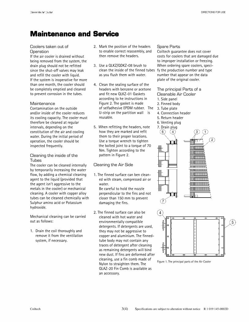
DIRECTIONS FOR USE
Coiltech 3(4) Specifications are subject to alteration without notice R 1 019 145-0002D
Maintenance and ServiceMaintenance and ServiceMaintenance and ServiceMaintenance and Service Coolers taken out of
Operation If the air cooler is drained without being removed from the system, the drain plug should not be refitted since the shut-off valves may leak and refill the cooler with liquid. If the system is inoperative for more than one month, the cooler should be completely emptied and cleaned to prevent corrosion in the tubes.
Maintenance Contamination on the outside and/or inside of the cooler reduces its cooling capacity. The cooler must therefore be cleaned at regular intervals, depending on the constitution of the air and cooling water. During the initial period of operation, the cooler should be inspected frequently.
Cleaning the inside of the Tubes The cooler can be cleaned internally by temporarily increasing the water flow, by adding a chemical cleaning agent to the liquid (provided that the agent isn’t aggressive to the metals in the cooler) or mechanical cleaning. A cooler with copper alloy tubes can be cleaned chemically with Sulphur amino acid or Potassium hydroxide.
Mechanical cleaning can be carried out as follows:
1. Drain the coil thoroughly and remove it from the ventilation system, if necessary.
2. Mark the position of the headers to enable correct reassembly, and then remove the headers.
3. Use a QLKZ/QDKZ-08 brush to
clean the inside of the finned tubes as you flush them with water.
4. Clean the sealing surface of the
headers with benzene or acetone and fit new QLKZ-01 Gaskets according to he instructions in Figure 2. The gasket is made of selfadhesive EPDM rubber. The U-strip on the partition wall is reusable.
5. When refitting the headers, note
how they are marked and refit them to their proper locations. Use a torque wrench to tighten
the bolted joint to a torque of 70 Nm. Tighten according to the pattern in Figure 2.
Cleaning the Air Side 1. The finned surface can ben clean-
ed with steam, compressed air or water. Be careful to hold the nozzle perpendicular to the fins and not
closer than 150 mm to prevent damaging the fins.
2. The finned surface can also be
cleaned with hot water and environmentally compatible detergents. If detergents are used, they may not be aggressive to copper and aluminium. The finned-tube body may not contain any traces of detergent after cleaning as remaining detergents will bind new dust. If fins are deformed after cleaning, use a fin comb made of Nylon to straighten them. The QLAZ-20 Fin Comb is available as an accessory.
Spare Parts Coiltech guarantee does not cover costs for coolers that are damaged due to improper installation or freezing. When ordering spare coolers, speci- fy the production number and type number that appear on the data plate of the original cooler.
The principal Parts of a Cleanable Air Cooler 1. Side panel 2. Finned body 3. Tube plate 4. Connection header 5. Return header 6. Venting plug 7. Drain plug
Figure 1. The principal parts of the Air Cooler

DIRECTIONS FOR USE
Coiltech 4(4) Specifications are subject to alteration without notice R 1 019 145-0002D
Maintenance and ServiceMaintenance and ServiceMaintenance and ServiceMaintenance and Service
Fitting the QLKZ-01 Replacement Gasket 1. Rubber gasket, 10 x 2 mm always to be replaced when
dismantling the headers. 2. Rubber U-strip Fit the rubber gasket so that it borders on the screw holes. Stretch the gasket outward in the corners. Cut the U-strip obliquely so that it follows the bending radius of the header. It should extend inward under the gasket. When you refit the headers, tighten the bolts in the order indicated by s1 – s8.
Tightening torque: 70 Nm Before start-up, the bolts are re-torqued to 70 Nm.
Figure 2. Fitting the gasket and U-strip
Coiltech AB: SE-614 81 Söderköping Phone +46 121-19100 Fax +46 121-10101 www.coiltech.com
Coiltech, Afrikalaan 303, BE-9000 Gent, Belgium Phone +32 9 218 71 30 Fax +32 9 218 71 39
Coiltech, Schönbrunner Allee 11 AT-1120 VIENNA, Austria Phone +43 1 81 20 206 Fax: +43 1 81 20 250
WuXi ECO Coils&Coolers Co.,Ltd. No.19 Xin Nan Zhong Road, Mei Cun Wuxi national High Tech Industrial Development PRC Post code: 214112 Phone +86 (0)510 88558031 Fax +86 (0)510 88558038 www.ecogroup.com [email protected]
Head Office: 33050 POCENIA (UD) | Via Giulio Locatelli, 22 Phone +39 0432.772.001 Fax +39 0432.779.594 www.ecogroup.com

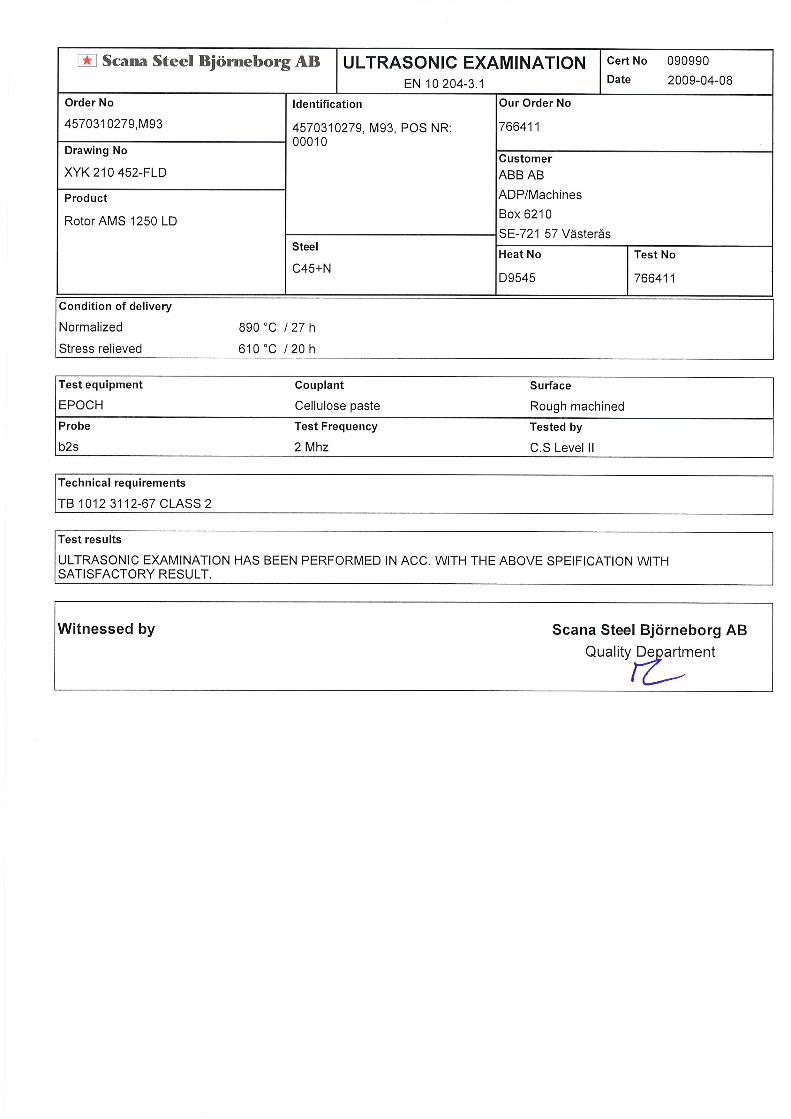
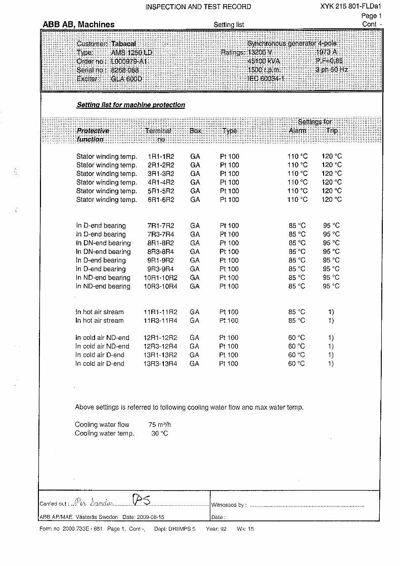
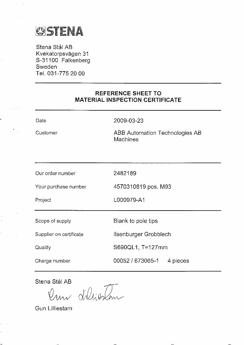

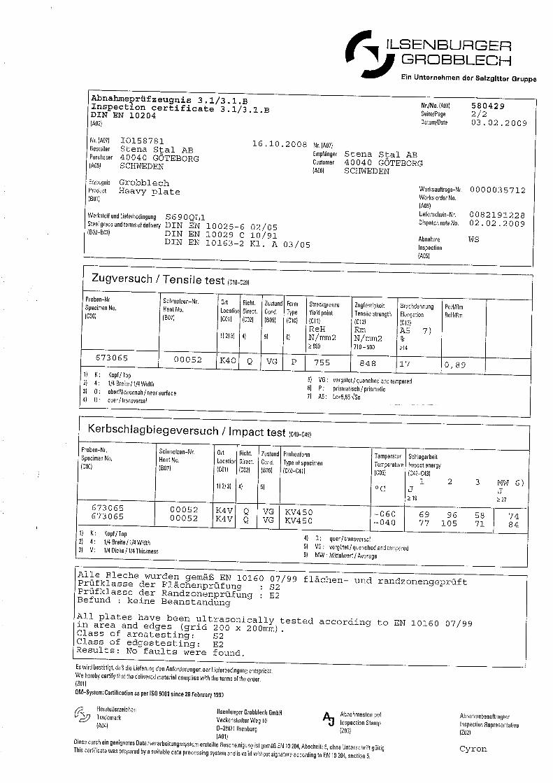


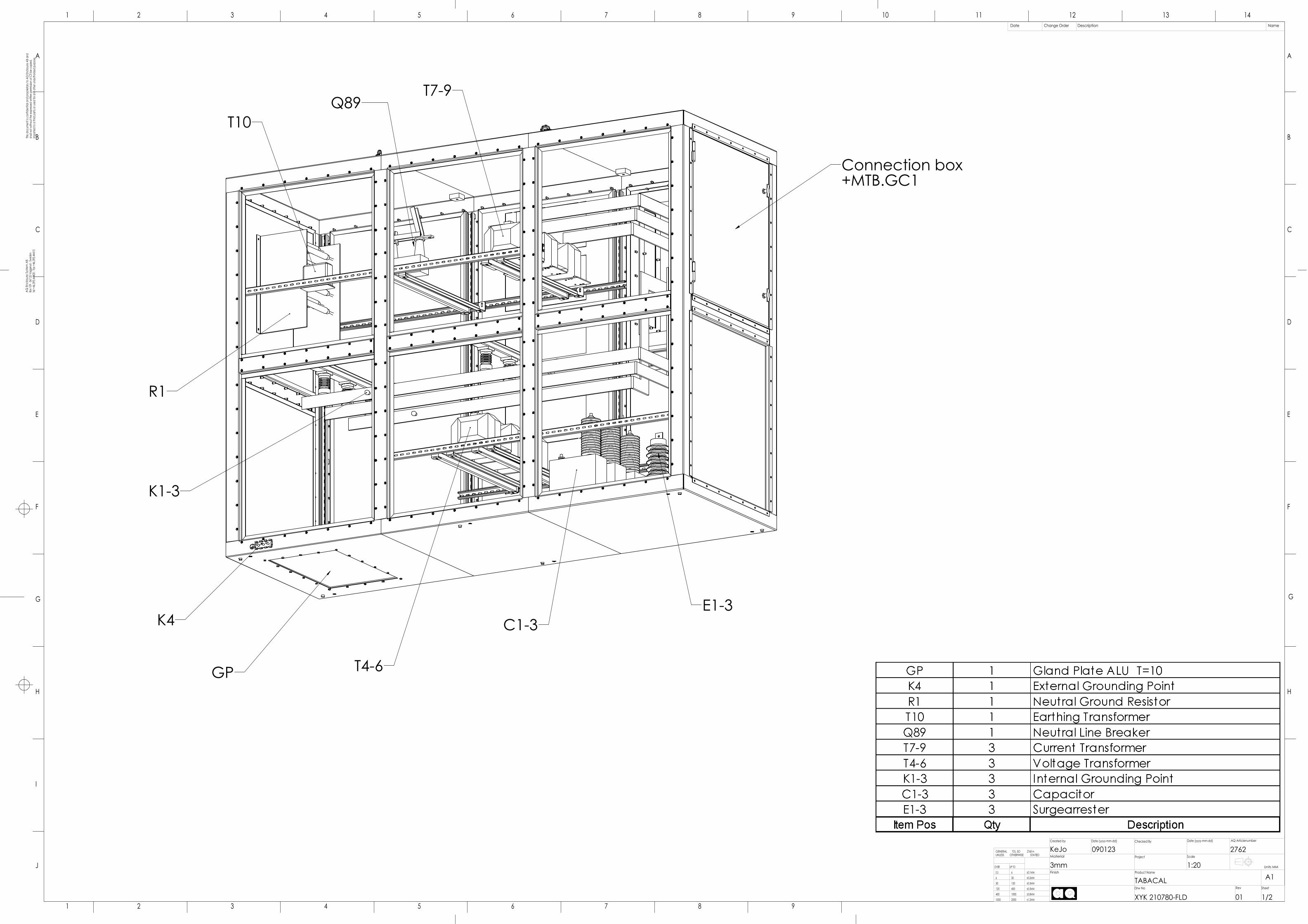
Connection box +MTB.GC1
GP
E1-3C1-3
T4-6
T7-9
T10
R1
K1-3
K4
Q89
1 2 3 4 5 6 7 8 9
J
I
H H
G G
F F
E E
D D
C C
B B
A A
1 2 3 4 5 6 7 8 9 10 11 12 13 14
±1.2MM20001000
±0.8MM1000400
±0.5MM400120
±0.3MM12030
±0.2MM306
±0.1MM60.5
OVER
STATEDOTHERWISE UNLESS 2768 m TOL. ISO GENERAL
UP TO 1:20
1/201XYK 210780-FLD
TABACAL
3mm
2762090123KeJo
Drw No Rev Sheet
Finish Product Name
Project ScaleMaterial
Created by Date (yyyy-mm-dd) Checked By Date (yyyy-mm-dd) AQ Articlenumber
Units MM
Date Change Order Description NameTh
is do
cum
ent is
con
fiden
tial a
nd p
ropr
ieta
ry to
AQ
Encl
osur
e AB
and
shal
l not
with
out t
he e
xpre
ssed
writt
en p
erm
ission
of C
TI be
cop
ied,
impa
rted
to a
third
par
ty or
use
d fo
r any
oth
er u
naut
horiz
ed p
urpo
se.
AQ E
nclo
sure
Sys
tem
AB
Box 1
09 - 5
67 22
Vag
geryd
- Swe
den
tel +
46.39
3.444
00 -
fax +
46.39
3.444
10
A1
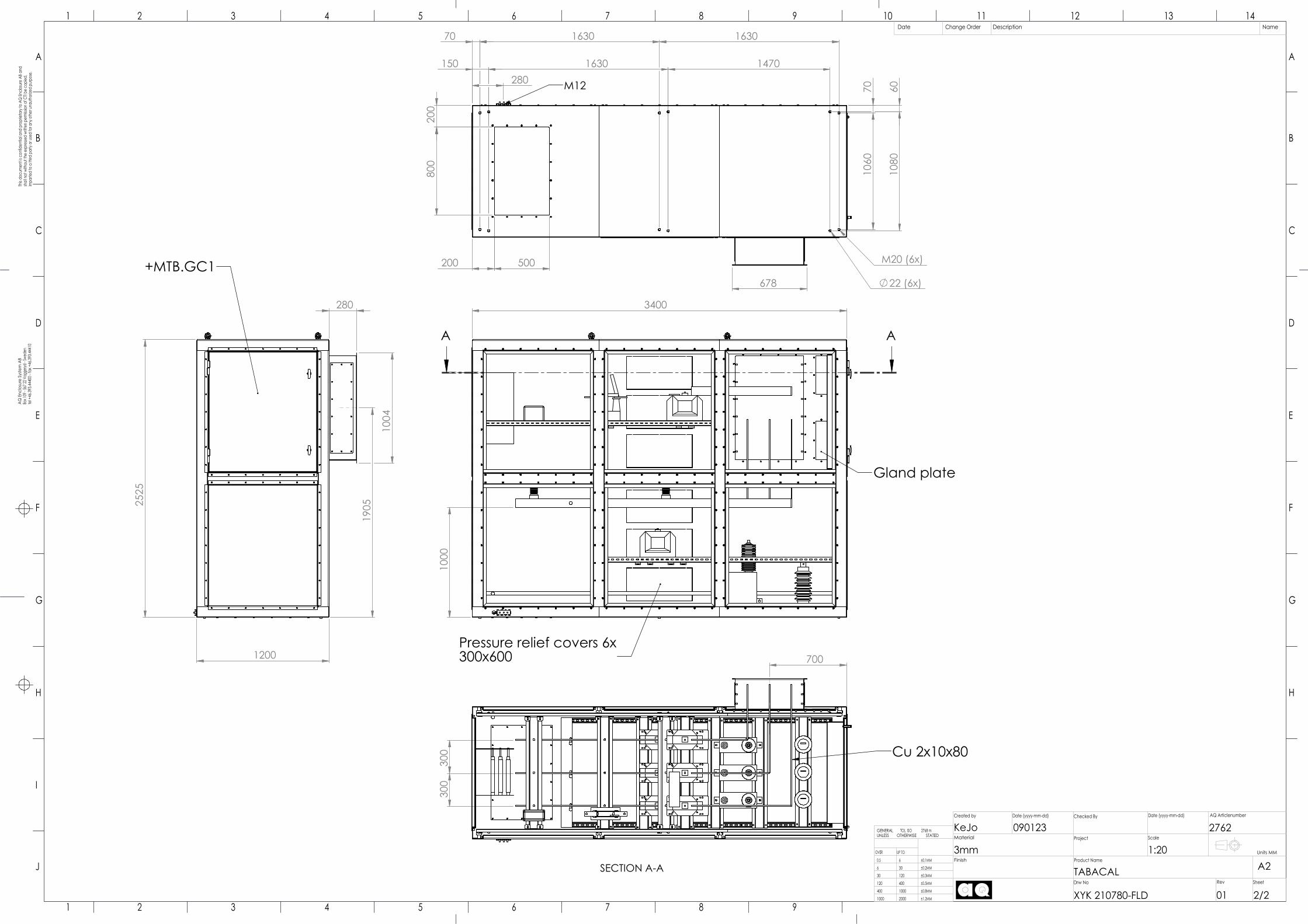
2525
1200
1004
280
1905
+MTB.GC1
3400
1000
AA
Pressure relief covers 6x300x600
Gland plate
300
300
700
SECTION A-A
Cu 2x10x80
800
200
280
22 (6x)
M20 (6x)
14701630150
1630163070
1080
1060
6070
200
500
678
M12
1 2 3 4 5 6 7 8 9
J
I
H H
G G
F F
E E
D D
C C
B B
A A
1 2 3 4 5 6 7 8 9 10 11 12 13 14
2762
±1.2MM20001000
±0.8MM1000400
±0.5MM400120
±0.3MM12030
±0.2MM306
±0.1MM60.5
OVER
STATEDOTHERWISE UNLESS 2768 m TOL. ISO GENERAL
UP TO 1:20
2/201XYK 210780-FLD
TABACAL
3mm
090123KeJo
Drw No Rev Sheet
Finish Product Name
Project ScaleMaterial
Created by Date (yyyy-mm-dd) Checked By Date (yyyy-mm-dd) AQ Articlenumber
Units MM
Date Change Order Description NameTh
is do
cum
ent is
con
fiden
tial a
nd p
ropr
ieta
ry to
AQ
Encl
osur
e AB
and
shal
l not
with
out t
he e
xpre
ssed
writt
en p
erm
ission
of C
TI be
cop
ied,
impa
rted
to a
third
par
ty or
use
d fo
r any
oth
er u
naut
horiz
ed p
urpo
se.
AQ E
nclo
sure
Sys
tem
AB
Box 1
09 - 5
67 22
Vag
geryd
- Swe
den
tel +
46.39
3.444
00 -
fax +
46.39
3.444
10
A2

Resp dept
Approved
Prepared
Based on
Take over dept
Pcl Reg No
Revision
Cont
Page
Lang
We reserve all rights in this document and in the informationcontained therein. Reproduction, use or disclosure to thirdparties without express authority is strictly forbidden.
ABB©
ABB AB, Machines
Suppl. documents, kind Identity No. Reservdelar XYK 200 500-FLD 902
Itm Qty Article No. Type Data Name Open document Note 1 2 2211 0348-2 Lagerbussning Bearing bushing 2 2 2211 0348-6 Lagerbussning, J-O Bearing bushing, J-O 3 4 2219 300-2 Lagerisolering, liten Bearing insulation,small 4 2 2219 300-4 Lagerisolation, stor Bearing insulation,large 5 4 2591 038-1 Luftfilter Air filter 6 4 3BSM 007334-A Axeltätning Shaft sealing 7 2 3BSM 005928-D Montering tätning Mounting of sealing 8 8 2219 303-4 Slang Hose 9 1 2515 291-L Slang för jacking-oil Hose for jacking-oil 10 8 3BSM 011092-1 Borste Brush
ISS Tabacal 808346 Orderbunden stycklista Siemens ltd Brazil 08-12-17 P-E Lindh Reservdelar Type des. AMS 1250LD 09-05-26 Anders Lindin Spare parts Intended for AP/MAA A sv Trade name L000979-A 1
XYK 200 500-FLD -
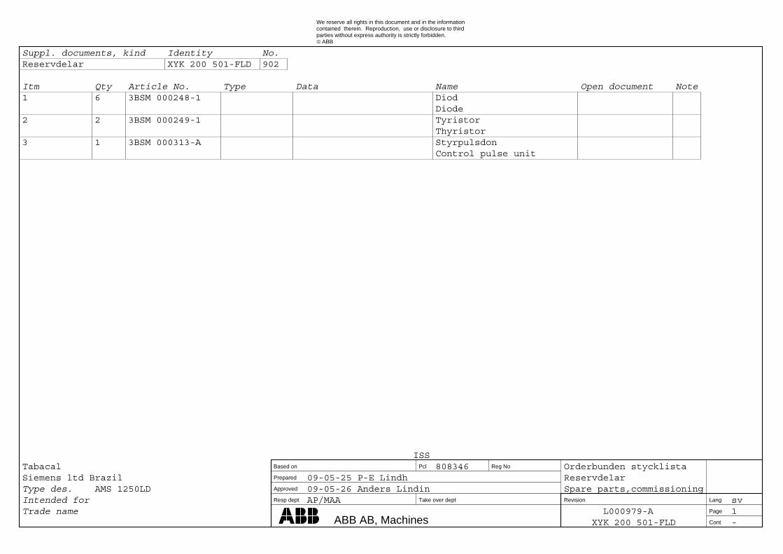
Resp dept
Approved
Prepared
Based on
Take over dept
Pcl Reg No
Revision
Cont
Page
Lang
We reserve all rights in this document and in the informationcontained therein. Reproduction, use or disclosure to thirdparties without express authority is strictly forbidden.
ABB©
ABB AB, Machines
Suppl. documents, kind Identity No. Reservdelar XYK 200 501-FLD 902
Itm Qty Article No. Type Data Name Open document Note 1 6 3BSM 000248-1 Diod Diode 2 2 3BSM 000249-1 Tyristor Thyristor 3 1 3BSM 000313-A Styrpulsdon Control pulse unit
ISS Tabacal 808346 Orderbunden stycklista Siemens ltd Brazil 09-05-25 P-E Lindh Reservdelar Type des. AMS 1250LD 09-05-26 Anders Lindin Spare parts,commissioning Intended for AP/MAA sv Trade name L000979-A 1
XYK 200 501-FLD -
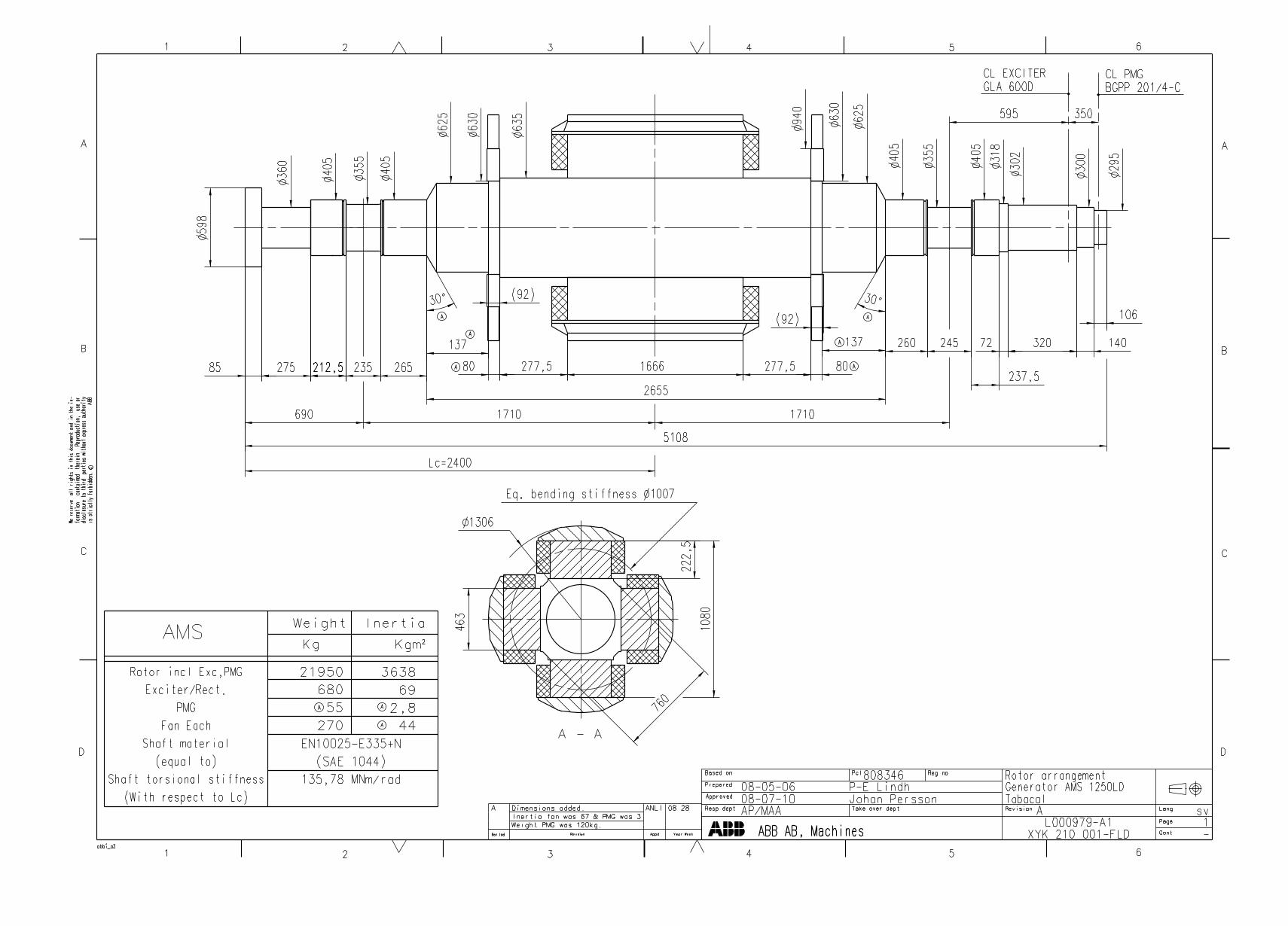
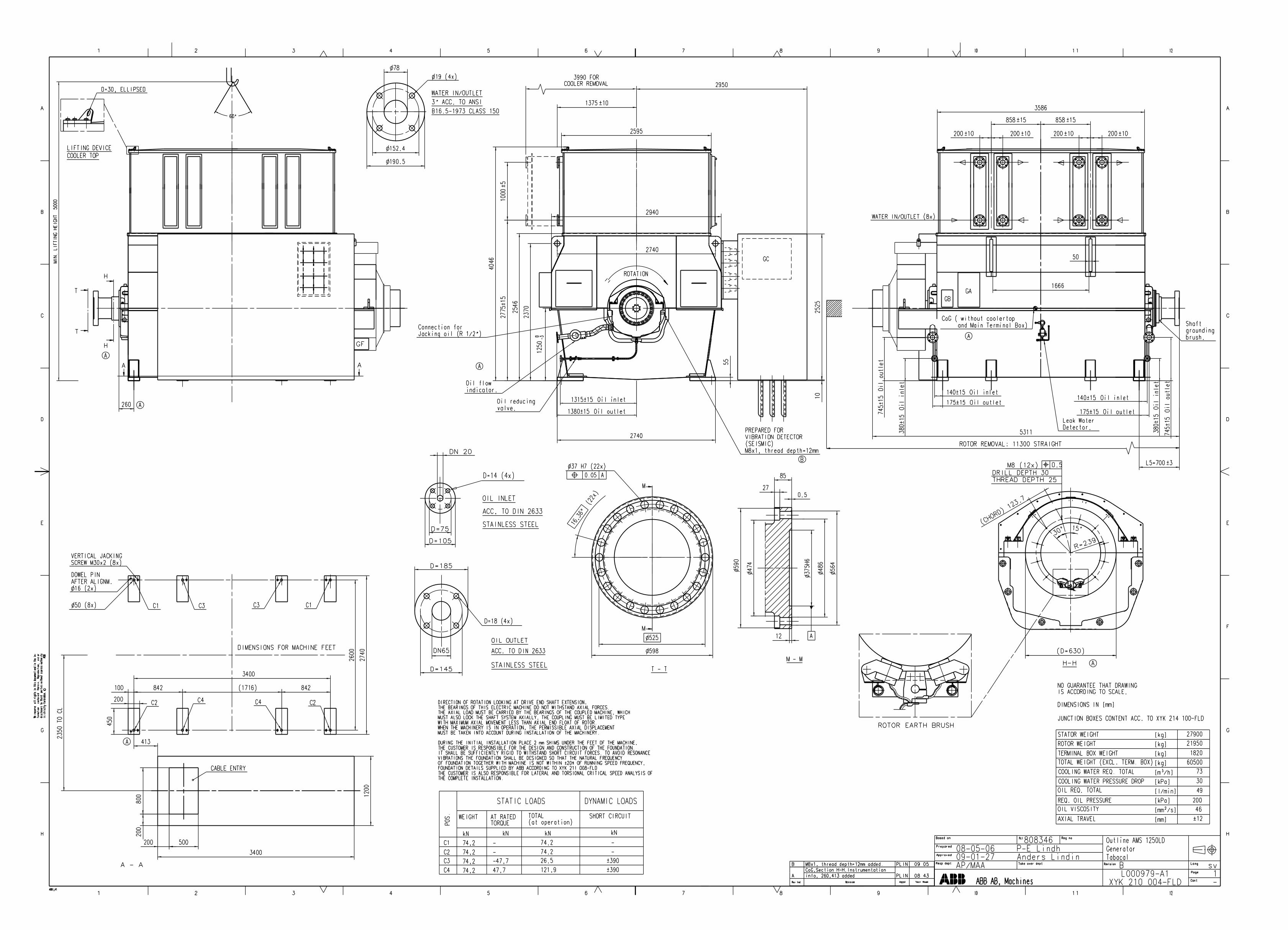
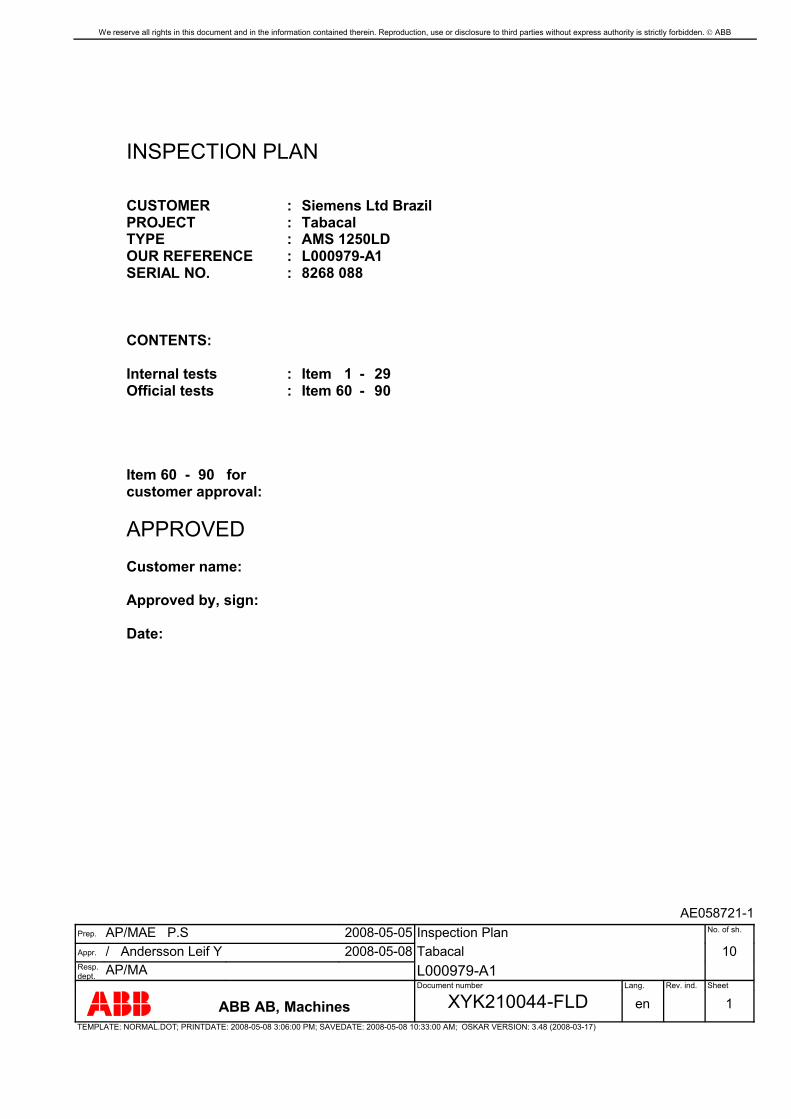
We reserve all rights in this document and in the information contained therein. Reproduction, use or disclosure to third parties without express authority is strictly forbidden. ABB
AE058721-1Prep. AP/MAE P.S 2008-05-05 Inspection Plan No. of sh.
Appr. / Andersson Leif Y 2008-05-08 Tabacal 10Resp. dept. AP/MA L000979-A1
Document number Lang. Rev. ind. Sheet
ABB AB, Machines XYK210044-FLD en 1TEMPLATE: NORMAL.DOT; PRINTDATE: 2008-05-08 3:06:00 PM; SAVEDATE: 2008-05-08 10:33:00 AM; OSKAR VERSION: 3.48 (2008-03-17)
INSPECTION PLAN
CUSTOMER : Siemens Ltd Brazil PROJECT : Tabacal TYPE : AMS 1250LD OUR REFERENCE : L000979-A1 SERIAL NO. : 8268 088
CONTENTS:
Internal tests : Item 1 - 29Official tests : Item 60 - 90
Item 60 - 90 forcustomer approval:
APPROVEDCustomer name:
Approved by, sign:
Date:

We reserve all rights in this document and in the information contained therein. Reproduction, use or disclosure to third parties without express authority is strictly forbidden. ABB
Document number Lang. Rev. ind. Sheet
ABB AB, Machines XYK210044-FLD en 2TEMPLATE: NORMAL.DOT; PRINTDATE: 2008-05-08 3:06:00 PM; SAVEDATE: 2008-05-08 10:33:00 AM; OSKAR VERSION: 3.48 (2008-03-17)
Key to the codes: Kodnyckel:Code 1 Kod 1Indicates place for testing Indikerar plats för provS = At the supplier to ABB S = Hos underleverantör till ABBL = In our workshop L = I egen verkstadT = In our testroom T = I eget provrumE = At the erection site E = På uppställningsplats
Code 2 Kod 2Indicates who will be present at and Indikerar vem som skall närvara vid ochsupervise the test övervaka provetD = Representative of the engineering D = Representant från orderavdelningen
departmentQ = Appointed internal inspector Q = Utsedd intern kontrollantX = Representative of customer X = Representant från kund
- Only visiting of test - Endast besök vid provW = Representative of customer W = Representant från kund
- Witnessed test. If customer or - Bevittnat prov. Om kund eller kundensrepresentative of customer is not in representant inte infinner sig i tid tilltime for test at the factory, the test provet, kommer provet att utföras utanis executed without his presence dennes närvaro
H = Representative of customer H = Representant från kund- Mandatory hold point. The test shall - Obligatorisk hållpunkt. Provet skall
be executed with presence of customer utföras med kund eller kundensor representative of customer representant närvarande
- = Not significate character - = Icke signifikant tecken
Code 3 Kod 3Indicates that testresults or certificate Indikerar att provresultatet eller certifikatshould be reported in writing and to skall rapporteras skriftligen och till vemwhom it should be sent protokollen skall skickasC = Customer via engineering department C = Kund via orderavdelningD = Engineering department D = OrderavdelningQ = Filed at test location or responsible Q = Arkiveras på provplats eller hos
department ansvarig avdelning- = Not significate character - = Icke signifikant tecken
Code 4 Kod 4Indicates the extent of testing Indikerar provets omfattning1 = Only first machine on the order 1 = Endast första maskinen i ordernA = All machines on the order A = Alla maskinerna i ordern

We reserve all rights in this document and in the information contained therein. Reproduction, use or disclosure to third parties without express authority is strictly forbidden. ABB
Document number Lang. Rev. ind. Sheet
ABB AB, Machines XYK210044-FLD en 3TEMPLATE: NORMAL.DOT; PRINTDATE: 2008-05-08 3:06:00 PM; SAVEDATE: 2008-05-08 10:33:00 AM; OSKAR VERSION: 3.48 (2008-03-17)
DOCUMENT CODEITEM DESCRIPTION FORM REMARKS
RECORD 1 2 3 4Internal tests:
1 Dimensions stacked stator Acc. drawing L Q Q ADimensioner plåtlagd stator 2000 733-009
XYK 215 100-FLD
2 Visual inspection of uninsulated Acc. drawing L Q Q Astator coil 2000 733E-537Okulärbesiktning av oisolerad XYK 215 142-FLDfläkt statorhärva
3 Testing of strand-insulation of 4104 016E-27 L Q Q Astator coil 2000 733E-608Provning av partisolering på XYK 215 710-FLDstatorhärvor
4 Impulse voltage test on stator 3BSM 000830 L Q Q Acoils 2000 733E-539Stötspänningsprov på stator- XYK 215 144-FLDhärvor
5 Impulse voltage test on stator 3BSM 000830 L Q Q Acoils in stator 2000 733E-580Stötspänningsprov på stator- XYK 215 442-FLDhärvor i stator
6 Dielectric tests of the stator 3BSM 000831 L Q Q Awinding before and after VPI 2000 733E-580Spänningsprov på statorlindning XYK 215 442-FLDföre och efter VPI
7 Visual inspection of wound 4104 016E-34 L Q Q Astator 2000 733E-580Okulärbesiktning av lindad XYK 215 442-FLDstator
8 Dimensions and run-outs of Acc. drawing L Q Q Arotorbody complete 2000 733E-378Dimensioner och kast på rotor- XYK 215 106-FLDstomme komplett
9 Shaft end with flange Acc. drawing L Q Q AUppmätning av hålbild på 2000 733-542axeltapp med fläns XYK 215 111-FLD
10 Dimensional check of machined Acc. drawing L Q Q Apole tips 2000 733E-609Dimensionskontroll av bearbetad XYK 215 711-FLDpolplatta

We reserve all rights in this document and in the information contained therein. Reproduction, use or disclosure to third parties without express authority is strictly forbidden. ABB
Document number Lang. Rev. ind. Sheet
ABB AB, Machines XYK210044-FLD en 4TEMPLATE: NORMAL.DOT; PRINTDATE: 2008-05-08 3:06:00 PM; SAVEDATE: 2008-05-08 10:33:00 AM; OSKAR VERSION: 3.48 (2008-03-17)
11 Dimension check of rotor coils Acc. drawing L Q Q ADimensionskontroll av 2000 733E-531rotorspolar XYK 215 125-FLD
12 High frequency test of rotor 3BSM 005428 L Q Q Acoils 2000 733E-531Högfrekvensprov på rotorspolar XYK 215 125-FLD
13 Tightening torque and angular Acc. drawing L Q Q Atightening of pole bolts 2000 733E-639Åtdragningsmoment och vinkel- XYK 215 463-FLDstyrd dragning av polbultar
14 Tightening torque for support to Acc. drawing L Q Q Arotor coils 2000 733E-639Åtdragningsmoment för spolstöd XYK 215 463-FLD
15 High frequency test on wound 3BSM 005427 L Q Q Arotor 2000 733E-639Högfrekvensprov på lindad rotor XYK 215 463-FLD
16 High voltage test on wound rotor 3BSM 005427 L Q Q AHögspänningsprov på lindad rotor 2000 733E-639
XYK 215 463-FLD
17 Impulse voltage test on wound 3BSM 005427 L Q Q Arotor 2000 733E-639Stötspänningsprov på lindad XYK 215 463-FLDrotor
18 Visual inspection of wound rotor Acc. drawing L Q Q AOkulärbesiktning av lindad rotor 2000 733E-639
XYK 215 463-FLD
19 Run-out of rotor complete, Acc. drawing L Q Q Arun-out of shaft end 2000 733E-546Kast på rotor komplett, kast på XYK 215 435-FLDaxeltapp
20 Measurement of rotor impedance 3BSM 005426 L Q Q Awithout stator 2000 733E-546Uppmätning av rotorimpedans utan XYK 215 435-FLDstator
21 Dimension check of bearing house Acc. drawing L Q Q ADimensionskontroll av lagerhus 2000 733E-264
XYK 215 708-FLD
22 Measurements of bearing liners Acc. drawing L Q Q Amounted in bearing shell 2000 733-156Mätning av lagerfoder monterad i XYK 215 152-FLDlagerskålen
We reserve all rights in this document and in the information contained therein. Reproduction, use or disclosure to third parties without express authority is strictly forbidden. ABB
Document number Lang. Rev. ind. Sheet
ABB AB, Machines XYK210044-FLD en 5TEMPLATE: NORMAL.DOT; PRINTDATE: 2008-05-08 3:06:00 PM; SAVEDATE: 2008-05-08 10:33:00 AM; OSKAR VERSION: 3.48 (2008-03-17)
23 Inspection of wound exciter 4104 016E-41 L Q Q Arotor 2000 733E-629Kontroll av lindad matarrotor XYK 215 469-FLD
24 Balancing of complete exciter 4104 016E-42 L Q Q Arotor 2000 733E-714Balansering av komplett XYK 215 701-FLDmatarrotor
25 Winding control of wound exciter 4104 016E-37 L Q Q Astator 2000 733E-626Lindningskontroll av lindad XYK 215 466-FLDmatarstator
26 Feet location Acc. drawing L Q Q AFotplattors placering 2000 733-545
XYK 215 160-FLD
27 Control of contact surface on 4107 011E-17 L Q Q Amachine foot 2000 733E-540Kontroll av fotplattornas XYK 215 131-FLDkontaktyta
28 Visual inspection of complete 4104 016E-18 T Q Q Amachine 2000 733E-574Okulär besiktning av komplett XYK 215 425-FLDmaskin
29 Weighing of machine, cooler top 3BSM 901 442 L Q Q Aand terminal box 2000 733E-573Vägning av maskin, kylartopp och XYK 215 420-FLDuttagslåda

We reserve all rights in this document and in the information contained therein. Reproduction, use or disclosure to third parties without express authority is strictly forbidden. ABB
Document number Lang. Rev. ind. Sheet
ABB AB, Machines XYK210044-FLD en 6TEMPLATE: NORMAL.DOT; PRINTDATE: 2008-05-08 3:06:00 PM; SAVEDATE: 2008-05-08 10:33:00 AM; OSKAR VERSION: 3.48 (2008-03-17)
DOCUMENT CODEITEM DESCRIPTION FORM REMARKS
RECORD 1 2 3 4Official tests:
60 Material check of blank for Acc. drawing S - C Arotorbody CertificateMaterialkontroll av ämne tillrotorkropp
61 Material check of blank to Acc. drawing S - C Apole tips CertificateMaterialkontroll av ämne tillpolplattor
62 Pressure test of water cooler Acc. drawing S - C ATryckprov av vattenkylare Certificate
63 Certificate for Pilot Exciter (PMG) Acc. drawing S - C ACertifikat för hjälpmatare (PMG) Certificate
64 Balancing of rotor complete 4107 011E-5 L Q C ABalansering rotor komplett 2000 733E-546
XYK 215 435-FLD
65 Radial bearing clearance 4107 011E-7 L Q C ARadiell frigång i lager 2000 733E-551
XYK 215 305-FLD
66 Air gap measurement 4107 011E-8 L Q C ALuftgapsmätning 2000 733E-529
XYK 215 150-FLD
67 Dissipationfactor ( tan delta) 4104 016E-43 T Q C Ameasurement on complete machine 2000 733E-596Förlustfaktormätning ( tan XYK 215 400-FLDdelta) på komplett maskin
68 Resistance measurement 4104 016E-5 T Q C AResistansmätning 2000 733E-552
XYK 215 310-FLD
69 Heat run at P.F. = 0 4104 016E-16 T W C 1Värmeprov vid cos ø = 0 2000 733E-558
XYK 215 340-FLD

We reserve all rights in this document and in the information contained therein. Reproduction, use or disclosure to third parties without express authority is strictly forbidden. ABB
Document number Lang. Rev. ind. Sheet
ABB AB, Machines XYK210044-FLD en 7TEMPLATE: NORMAL.DOT; PRINTDATE: 2008-05-08 3:06:00 PM; SAVEDATE: 2008-05-08 10:33:00 AM; OSKAR VERSION: 3.48 (2008-03-17)
70 No-load losses at P.F. = 1 4104 016E-6 T W C ATomgångsförluster vid cos ø = 1 2000 733E-557
XYK 215 335-FLD
71 No-load characteristic and 4104 016E-6 T W C Alosses 2000 733E-557Tomgångskurva och -förluster XYK 215 335-FLD
72 Short-circuit characteristic and 4104 016E-7 T W C Alosses 2000 733E-557Kortslutningskurva och XYK 215 335-FLD-förluster
73 Load point at P.F. = 0 4104 016E-15 T W C ABelastningspunkt vid cos ø = 0 2000 733E-557
XYK 215 335-FLD
74 Shaft voltage measurement 4104 016E-14 T W C AMätning av axelspänning 2000 733E-554
XYK 215 320-FLD
75 Phase sequence and terminal 4104 016E-10 T W C Amarking 2000 733E-555Fasföljd och uttagsmärkning XYK 215 325-FLD
76 Voltage and current balance 4104 016E-11 T W C ASpännings- och strömbalans 2000 733E-569
XYK 215 395-FLD
77 Overspeed test 4104 016E-12 T W C ARusningsprov 2000 733E-556
XYK 215 330-FLD
78 Vibration measurements 4107 011E-11 T W C AVibrationsmätningar 2000 733E-560
XYK 215 350-FLD
79 Vibration measurement during 4107 011E-15 T W C Aretardation or acceleration 2000 733E-560Vibrationsmätning under XYK 215 354-FLDutlöpning eller upprullning
80 Functional test of jacking oil T W C Asystem 2000 733E-649Funktionstest av jacking oil XYK 215 431-FLDsystem

We reserve all rights in this document and in the information contained therein. Reproduction, use or disclosure to third parties without express authority is strictly forbidden. ABB
Document number Lang. Rev. ind. Sheet
ABB AB, Machines XYK210044-FLD en 8TEMPLATE: NORMAL.DOT; PRINTDATE: 2008-05-08 3:06:00 PM; SAVEDATE: 2008-05-08 10:33:00 AM; OSKAR VERSION: 3.48 (2008-03-17)
81 Calibration of orifice in lubricating T Q C Aoil system 2000 733E-575Kalibrering av strypbrickor till XYK 215 430-FLDsmörjolje systemet
82 PMG, Output voltage and Acc.drawing T W C Afrequency 2000 733E-576PMG, utspänning och frekvens XYK 215 438-FLD
83 Control of leak water detector 3BSM 003641-1 T W C AKontroll av läckvattenvakt 2000 733E-588
XYK 215 450-FLD
84 Magnetic neutral pos., axial 4107 011E-9 T W C Aplay in bearing and distance 2000 733E-553shaft-end to footplate XYK 215 315-FLDMagnetiskt neutralläge, axielltlagerspel och avstånd axeltappfotplatta
85 Measurement of insulation 4104 016E-3 T W C Aresistance before and after 2000 733E-561dielectric test XYK 215 355-FLDMätning av isolationsresistansföre och efter högspänningsprov
86 Dielectric test 4104 016E-13 T W C AHögspänningsprov 2000 733E-561
XYK 215 355-FLD
87 Test of terminal box 4104 016E-25 T W C AProvning av uttagslåda 2000 733E-570
XYK 215 405-FLD

We reserve all rights in this document and in the information contained therein. Reproduction, use or disclosure to third parties without express authority is strictly forbidden. ABB
Document number Lang. Rev. ind. Sheet
ABB AB, Machines XYK210044-FLD en 9TEMPLATE: NORMAL.DOT; PRINTDATE: 2008-05-08 3:06:00 PM; SAVEDATE: 2008-05-08 10:33:00 AM; OSKAR VERSION: 3.48 (2008-03-17)
88 Determination of rated 4104 016E-20 T D C Aexcitation current 2000 733E-611Bestämning av märkmagnetisering XYK 215 490-FLD
89 Determination of efficiency at IEC 60034-2 cl. 11 T D C Arated P.F. and 100, 75, 50 and 2000 733E-61225% load XYK 215 480-FLDBestämning av verkningsgradenvid märk cos ø och 100, 75, 50och 25% last
90 Settings list for machine T D C Aprotection 2000 733E-651Inställningslista för XYK 215 801-FLDmaskinskydd

We reserve all rights in this document and in the information contained therein. Reproduction, use or disclosure to third parties without express authority is strictly forbidden. ABB
Document number Lang. Rev. ind. Sheet
ABB AB, Machines XYK210044-FLD en 10TEMPLATE: NORMAL.DOT; PRINTDATE: 2008-05-08 3:06:00 PM; SAVEDATE: 2008-05-08 10:33:00 AM; OSKAR VERSION: 3.48 (2008-03-17)
REVISIONRev.ind.
Page (P)Chapt.(C)
Description DateDept./Init.
We reserve all rights in this document and in the information contained therein. Reproduction, use or disclosure to third parties without express authority is strictly forbidden. ABB
AE058721Prep. AP/MAE P.S 2008-05-05 Technical Specification No. of sh.
Appr. / Carlquist Kristina 30/01/2009 Tabacal 9Resp. dept. AP/MA L000979-A1
Document number Lang. Rev. ind. Sheet
ABB AB, Machines XYK210045-FLD en A 1TEMPLATE: NORMAL.DOT; PRINTDATE: 1/30/2009 12:35:00 PM; SAVEDATE: 1/30/2009 12:38:00 PM; OSKAR VERSION: 3.48 (2008-03-17)
TECHNICAL SPECIFICATION FOR BRUSHLESS SYNCHRONOUS GENERATOR
CLIENT : Siemens Ltd Brazil PROJECT : Tabacal TYPE : AMS 1250LD OUR REFERENCE : L000979-A1 DRIVEN BY : Steam Turbine DATE : 2008-05-05___________________________________________________
SECTION PAGE
A. RATED DATA 2B. STANDARDS 2C. OTHER PERFORMANCE DATA 2D. SITE CONDITIONS 3F. INSTALLATION DATA 4G. INCLUDED ACCESSORIES 5H. WORKSHOP TESTS 8
ENCLOSURE NUMBER
INSPECTION PLAN XYK 210 044-FLD
GENERATOR CURVES : XYK 210 094-FLD
PAGE- EFFICIENCY CURVES 1- SATURATION CURVES - A 2- V-CURVES 3- CAPABILITY DIAGRAM 4- GENERATOR OVERLOAD CURVES 5- NEGATIVE SEQUENCE CURRENT CAPABILITY CURVES 6- DECREMENT CURVES 7
SHORT CIRCUIT EQUATIONS XYK 210 089-FLD

We reserve all rights in this document and in the information contained therein. Reproduction, use or disclosure to third parties without express authority is strictly forbidden. ABB
Document number Lang. Rev. ind. Sheet
ABB AB, Machines XYK210045-FLD en A 2TEMPLATE: NORMAL.DOT; PRINTDATE: 1/30/2009 12:35:00 PM; SAVEDATE: 1/30/2009 12:38:00 PM; OSKAR VERSION: 3.48 (2008-03-17)
A. RATED DATA
Output kVA : 45100 Power factor ( overexcited ) : 0.85 Voltage V (±5%) : 13200 Frequency Hz (±5%) : 50 Speed r/min : 1500 Current A : 1973 Exciter type : GLA 600D Excitation V/A : 103 / 11
B. STANDARDS
Applicable standards : IEC 60034-1 Insulation class stator and exciter : F Insulation class main rotor : H Temperature rise, stator within class : B Temperature rise, rotor within class : B
C. OTHER PERFORMANCE DATA
Efficiency at P.F. 0.85 and 100 / 75 / 50 / 25 % load % : 98.43 98.35 98.01 96.68
Reactances: - Xd (±15%) % : 192 - Xd' unsat/sat " % : 30.5 / 26.2 - Xd" unsat/sat " % : 19.6 / 16.7 - X0 % : 8.1 - X2 % : 19.6
Time constants: - Td' s : 1.12 - Td" s : 0.028 - Td0' s : 9.57 - Ta s : 0.18
Excitation main machine: - voltage no load V : 69 - voltage full load V : 178 - current no load A : 208 - current full load A : 540

We reserve all rights in this document and in the information contained therein. Reproduction, use or disclosure to third parties without express authority is strictly forbidden. ABB
Document number Lang. Rev. ind. Sheet
ABB AB, Machines XYK210045-FLD en A 3TEMPLATE: NORMAL.DOT; PRINTDATE: 1/30/2009 12:35:00 PM; SAVEDATE: 1/30/2009 12:38:00 PM; OSKAR VERSION: 3.48 (2008-03-17)
Sudden short circuit current (peak) kA : 33 Short circuit ratio % : 57
Max. field forcing for 10 seconds (percentage of rated excitation) % : 160 Sustained short circuit, stator current for 10 seconds at symetrical conditions % : 235
Max. permissible overspeed r/min : 1800
Output with one cooler element out of service % : 100
Max. continuous negative sequence current % : 8 Fault condition capability (I2/IN)2t s : 20
Allowed current harmonic content, with base 45100 kVA
Harmonic Current content
5 th 2.0 %7 th 1.7 %11 th 1.2 %13 th 1.1 %17 th 1.0 %19 th 1.0 %23 th 0.9 %25 th 0.6 %
If the current harmonic content is higher than above values, the temperature of the machine may rise above the specified limits.
D. SITE CONDITIONS
Ambient temperature range °C : 0 - +50 Altitude m : < 1000 Location : Indoors Water temperature range °C : 10 - +30 Hazardous area classification : Non hazardous area Seismic zone : Acc. to UBC, Zone 4
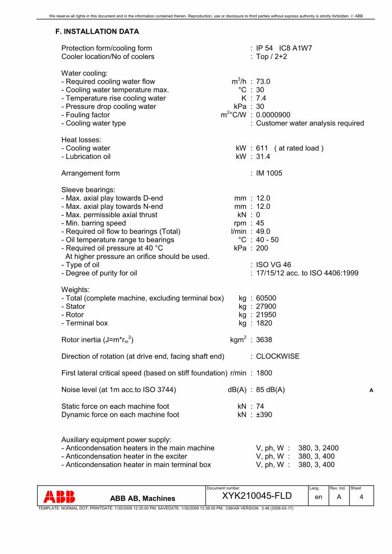
We reserve all rights in this document and in the information contained therein. Reproduction, use or disclosure to third parties without express authority is strictly forbidden. ABB
Document number Lang. Rev. ind. Sheet
ABB AB, Machines XYK210045-FLD en A 4TEMPLATE: NORMAL.DOT; PRINTDATE: 1/30/2009 12:35:00 PM; SAVEDATE: 1/30/2009 12:38:00 PM; OSKAR VERSION: 3.48 (2008-03-17)
F. INSTALLATION DATA
Protection form/cooling form : IP 54 IC8 A1W7 Cooler location/No of coolers : Top / 2+2
Water cooling: - Required cooling water flow m3/h : 73.0 - Cooling water temperature max. °C : 30 - Temperature rise cooling water K : 7.4 - Pressure drop cooling water kPa : 30 - Fouling factor m2°C/W : 0.0000900 - Cooling water type : Customer water analysis required
Heat losses: - Cooling water kW : 611 ( at rated load ) - Lubrication oil kW : 31.4
Arrangement form : IM 1005
Sleeve bearings: - Max. axial play towards D-end mm : 12.0 - Max. axial play towards N-end mm : 12.0 - Max. permissible axial thrust kN : 0 - Min. barring speed rpm : 45 - Required oil flow to bearings (Total) l/min : 49.0 - Oil temperature range to bearings °C : 40 - 50 - Required oil pressure at 40 °C kPa : 200 At higher pressure an orifice should be used. - Type of oil : ISO VG 46 - Degree of purity for oil : 17/15/12 acc. to ISO 4406:1999
Weights: - Total (complete machine, excluding terminal box) kg : 60500 - Stator kg : 27900 - Rotor kg : 21950 - Terminal box kg : 1820
Rotor inertia (J=m*rm2) kgm2 : 3638
Direction of rotation (at drive end, facing shaft end) : CLOCKWISE
First lateral critical speed (based on stiff foundation) r/min : 1800
Noise level (at 1m acc.to ISO 3744) dB(A) : 85 dB(A) A
Static force on each machine foot kN : 74 Dynamic force on each machine foot kN : ±390
Auxiliary equipment power supply: - Anticondensation heaters in the main machine V, ph, W : 380, 3, 2400 - Anticondensation heater in the exciter V, ph, W : 380, 3, 400 - Anticondensation heater in main terminal box V, ph, W : 380, 3, 400
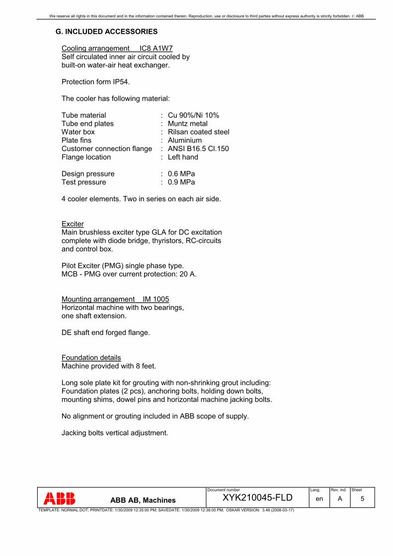
We reserve all rights in this document and in the information contained therein. Reproduction, use or disclosure to third parties without express authority is strictly forbidden. ABB
Document number Lang. Rev. ind. Sheet
ABB AB, Machines XYK210045-FLD en A 5TEMPLATE: NORMAL.DOT; PRINTDATE: 1/30/2009 12:35:00 PM; SAVEDATE: 1/30/2009 12:38:00 PM; OSKAR VERSION: 3.48 (2008-03-17)
G. INCLUDED ACCESSORIES
Cooling arrangement IC8 A1W7 Self circulated inner air circuit cooled by built-on water-air heat exchanger.
Protection form IP54.
The cooler has following material:
Tube material : Cu 90%/Ni 10% Tube end plates : Muntz metal Water box : Rilsan coated steel Plate fins : Aluminium Customer connection flange : ANSI B16.5 Cl.150 Flange location : Left hand
Design pressure : 0.6 MPa Test pressure : 0.9 MPa
4 cooler elements. Two in series on each air side.
Exciter Main brushless exciter type GLA for DC excitation complete with diode bridge, thyristors, RC-circuits and control box.
Pilot Exciter (PMG) single phase type. MCB - PMG over current protection: 20 A.
Mounting arrangement IM 1005 Horizontal machine with two bearings, one shaft extension.
DE shaft end forged flange.
Foundation details Machine provided with 8 feet.
Long sole plate kit for grouting with non-shrinking grout including: Foundation plates (2 pcs), anchoring bolts, holding down bolts, mounting shims, dowel pins and horizontal machine jacking bolts.
No alignment or grouting included in ABB scope of supply.
Jacking bolts vertical adjustment.

We reserve all rights in this document and in the information contained therein. Reproduction, use or disclosure to third parties without express authority is strictly forbidden. ABB
Document number Lang. Rev. ind. Sheet
ABB AB, Machines XYK210045-FLD en A 6TEMPLATE: NORMAL.DOT; PRINTDATE: 1/30/2009 12:35:00 PM; SAVEDATE: 1/30/2009 12:38:00 PM; OSKAR VERSION: 3.48 (2008-03-17)
Bearings Sleeve bearings suitable for flood oil lubrication provided by others, connection at left side on each bearing.
The lube oil drain pressure must be less than or equal to the machine ambient pressure. An oil drain pressure of 200-1000 Pa lower than the bearing ambient is recommended.
Customer connection flange acc. to DIN.
Inlet pipe in stainless steel. Outlet pipe in stainless steel.
Lockable pressure reducing valve in stainless steel.
Provision for jacking oil only.
Emergency oil requirement
Main terminal Heaters in HV terminal box. Large stator terminal box, right side. Stator terminal box protection IP54 with all 12 ends brought out and neutral point terminated inside the box. Connection from underneath. Grounding clamps inside and outside.
The main terminal box is delivered as a loose item, assembly on site is not included in ABB's scope of supply.
The main terminal box needs to be supported from beneath. Supports are not included in ABB's scope of supply. For terminal box weight see section F.

We reserve all rights in this document and in the information contained therein. Reproduction, use or disclosure to third parties without express authority is strictly forbidden. ABB
Document number Lang. Rev. ind. Sheet
ABB AB, Machines XYK210045-FLD en A 7TEMPLATE: NORMAL.DOT; PRINTDATE: 1/30/2009 12:35:00 PM; SAVEDATE: 1/30/2009 12:38:00 PM; OSKAR VERSION: 3.48 (2008-03-17)
Line side
3 - Surge capacitors 3 - Lightning arrestors 3 - Voltage transformers 1 - Earthing device 3 phase, ball-bolt.
Neutral side
3 - Current transformers with 2 cores 1 - Current transformer with single core 1 - Neutral grounding resistor, 10 A for 10 sec. 1 - Low voltage contactor
1 – Grounding switch with auxiliary contacts A
Anticondensation heaters Standard 1 phase elements for 3 phase supply.
In both main machine, exciter and terminal box.
Termination in separate boxes (normally opposite main supply side).
The anticondensation heaters should always be connected during stand still.
Measurement and control Resistance temperature detectors All PT100 double elements (excl. stator) DIN.
6 in the stator winding 2 in each bearing 2 in cold air 1 in hot air
Flow control glass in oil outlet, carbon steel, 1 per bearing. DIN-flanges.
Cooling water leakage detector, brass, capacitive sensor with switching amplifier, 230 Vac.
Shaft grounding brush on D-end.
Painted carbon steel junction boxes provided with standard cable glands.

We reserve all rights in this document and in the information contained therein. Reproduction, use or disclosure to third parties without express authority is strictly forbidden. ABB
Document number Lang. Rev. ind. Sheet
ABB AB, Machines XYK210045-FLD en A 8TEMPLATE: NORMAL.DOT; PRINTDATE: 1/30/2009 12:35:00 PM; SAVEDATE: 1/30/2009 12:38:00 PM; OSKAR VERSION: 3.48 (2008-03-17)
Surface treatment Standard industrial coating acc. to ISO 12944 C2.
Primer coating - modified epoxy1 : 60 µm. Top coating - modified epoxy1 : 60 µm. 1The binder is an acid cured epoxidized oil. Standard colour : Blue NCS 4822-B05G
H. WORKSHOP TESTS
ABB AB Machines standard procedure is to perform a type test for a single machine order. If two or more identical machines are ordered, then a type test is performed on the first machine and routine tests on the remaining machines.
Proposed workshop tests according to enclosed INSPECTION PLAN are part of our manufacturing program and are part of the quoted price of the machine.
Witnessing of testing
Participation in a test specially arranged, time to be agreed between ABB AB Machines and customer, 2 weeks advance notice, date will be confirmed 1 week prior to scheduled test date. The performance calculations are carried out and presented to customer during his visit.

We reserve all rights in this document and in the information contained therein. Reproduction, use or disclosure to third parties without express authority is strictly forbidden. ABB
Document number Lang. Rev. ind. Sheet
ABB AB, Machines XYK210045-FLD en A 9TEMPLATE: NORMAL.DOT; PRINTDATE: 1/30/2009 12:35:00 PM; SAVEDATE: 1/30/2009 12:38:00 PM; OSKAR VERSION: 3.48 (2008-03-17)
REVISIONRev.ind.
Page (P)Chapt.(C)
Description DateDept./Init.
A P4P7
Sound level updated to 85 dB(A)1 grounding switch added
MAS/KC2009-01-30
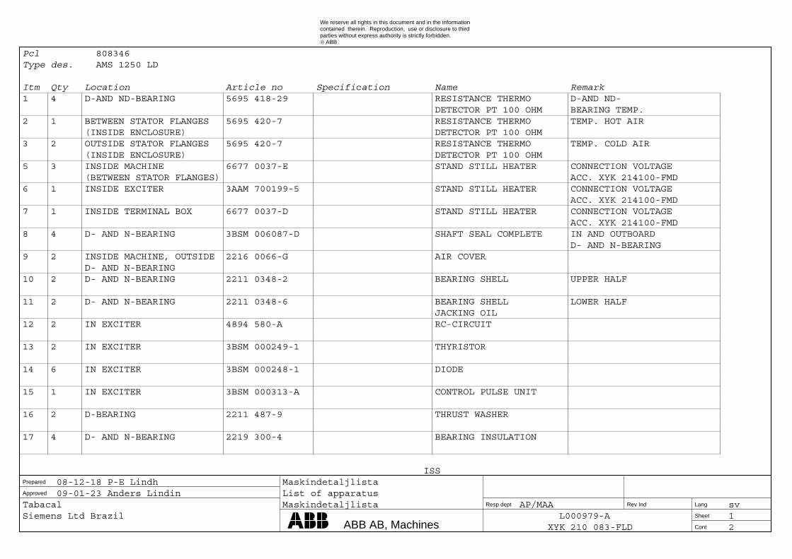
Approved
Prepared
Resp dept Rev Ind
Cont
Sheet
Lang
We reserve all rights in this document and in the informationcontained therein. Reproduction, use or disclosure to thirdparties without express authority is strictly forbidden.
ABB©
ABB AB, Machines
Pcl 808346 Type des. AMS 1250 LD
Itm Qty Location Article no Specification Name Remark 1 4 D-AND ND-BEARING 5695 418-29 RESISTANCE THERMO D-AND ND- DETECTOR PT 100 OHM BEARING TEMP. 2 1 BETWEEN STATOR FLANGES 5695 420-7 RESISTANCE THERMO TEMP. HOT AIR (INSIDE ENCLOSURE) DETECTOR PT 100 OHM 3 2 OUTSIDE STATOR FLANGES 5695 420-7 RESISTANCE THERMO TEMP. COLD AIR (INSIDE ENCLOSURE) DETECTOR PT 100 OHM 5 3 INSIDE MACHINE 6677 0037-E STAND STILL HEATER CONNECTION VOLTAGE (BETWEEN STATOR FLANGES) ACC. XYK 214100-FMD 6 1 INSIDE EXCITER 3AAM 700199-5 STAND STILL HEATER CONNECTION VOLTAGE ACC. XYK 214100-FMD 7 1 INSIDE TERMINAL BOX 6677 0037-D STAND STILL HEATER CONNECTION VOLTAGE ACC. XYK 214100-FMD 8 4 D- AND N-BEARING 3BSM 006087-D SHAFT SEAL COMPLETE IN AND OUTBOARD D- AND N-BEARING 9 2 INSIDE MACHINE, OUTSIDE 2216 0066-G AIR COVER D- AND N-BEARING 10 2 D- AND N-BEARING 2211 0348-2 BEARING SHELL UPPER HALF 11 2 D- AND N-BEARING 2211 0348-6 BEARING SHELL LOWER HALF JACKING OIL 12 2 IN EXCITER 4894 580-A RC-CIRCUIT 13 2 IN EXCITER 3BSM 000249-1 THYRISTOR 14 6 IN EXCITER 3BSM 000248-1 DIODE 15 1 IN EXCITER 3BSM 000313-A CONTROL PULSE UNIT 16 2 D-BEARING 2211 487-9 THRUST WASHER 17 4 D- AND N-BEARING 2219 300-4 BEARING INSULATION
ISS 08-12-18 P-E Lindh Maskindetaljlista 09-01-23 Anders Lindin List of apparatus Tabacal Maskindetaljlista AP/MAA sv Siemens Ltd Brazil L000979-A 1
XYK 210 083-FLD 2

Approved
Prepared
Resp dept Rev Ind
Cont
Sheet
Lang
We reserve all rights in this document and in the informationcontained therein. Reproduction, use or disclosure to thirdparties without express authority is strictly forbidden.
ABB©
ABB AB, Machines
Itm Qty Location Article no Specification Name Remark 18 2 D- AND N-BEARING 2219 300-5 BEARING INSULATION 19 1 AT SHAFT ON D-BEARING 3BSM 011092-1 EARTH BRUSH 20 1 D-BEARING 4395 917-2 BRUSH HOLDER 21 4 D- AND N-BEARING 2591 038-1 AIR FILTER 22 20 INSIDE BOX GA 5248 152-1 VARISTOR 23 1 OUTSIDE MACHINE 3BSM 005679-1 LEAK WATER DETECTOR
ISS 08-12-18 P-E Lindh Maskindetaljlista 09-01-23 Anders Lindin List of apparatus Tabacal Maskindetaljlista AP/MAA sv Siemens Ltd Brazil L000979-A 2
XYK 210 083-FLD -

We reserve all rights in this document and in the information contained therein. Reproduction, use or disclosure to third parties without express authority is strictly forbidden. ABB
AE058721Prep. AP/MAE P.S 2008-05-05 Short circuit equations No. of sh.
Appr. / Sandin Per 2008-05-08 Tabacal 2Resp. dept. AP/MA L000979-A1
Document number Lang. Rev. ind. Sheet
ABB AB, Machines XYK210089-FLD en 1TEMPLATE: NORMAL.DOT; PRINTDATE: 2008-05-08 10:41:00 AM; SAVEDATE: 2008-05-08 10:25:00 AM; OSKAR VERSION: 3.48 (2008-03-17)
Formulas for torsional analysis calculations
Airgap torque equation - 3-phase short circuit
Torque(t) = 6.72 * e(-t/0.136) * sin(wt) + 1.47 * e(-t/0.122) p.u.
Max. torque = 7.90 p.u. after 4.89 ms
Airgap torque equation - 2-phase short circuit
Torque(t) = 5.29 * e(-t/0.226) * sin(wt) - 2.65 * e(-t/0.708) * sin(2wt) + 1.47 * e(-t/0.370) p.u.
Max. torque = 8.17 p.u. after 6.66 ms
Rated torque: 1.0 p.u. = 247.86 kNm
t = time in seconds
w = 2 * pi * 50 at 50 Hz line frequency
We reserve all rights in this document and in the information contained therein. Reproduction, use or disclosure to third parties without express authority is strictly forbidden. ABB
Document number Lang. Rev. ind. Sheet
ABB AB, Machines XYK210089-FLD en 2TEMPLATE: NORMAL.DOT; PRINTDATE: 2008-05-08 10:41:00 AM; SAVEDATE: 2008-05-08 10:25:00 AM; OSKAR VERSION: 3.48 (2008-03-17)
REVISIONRev.ind.
Page (P)Chapt.(C)
Description DateDept./Init.
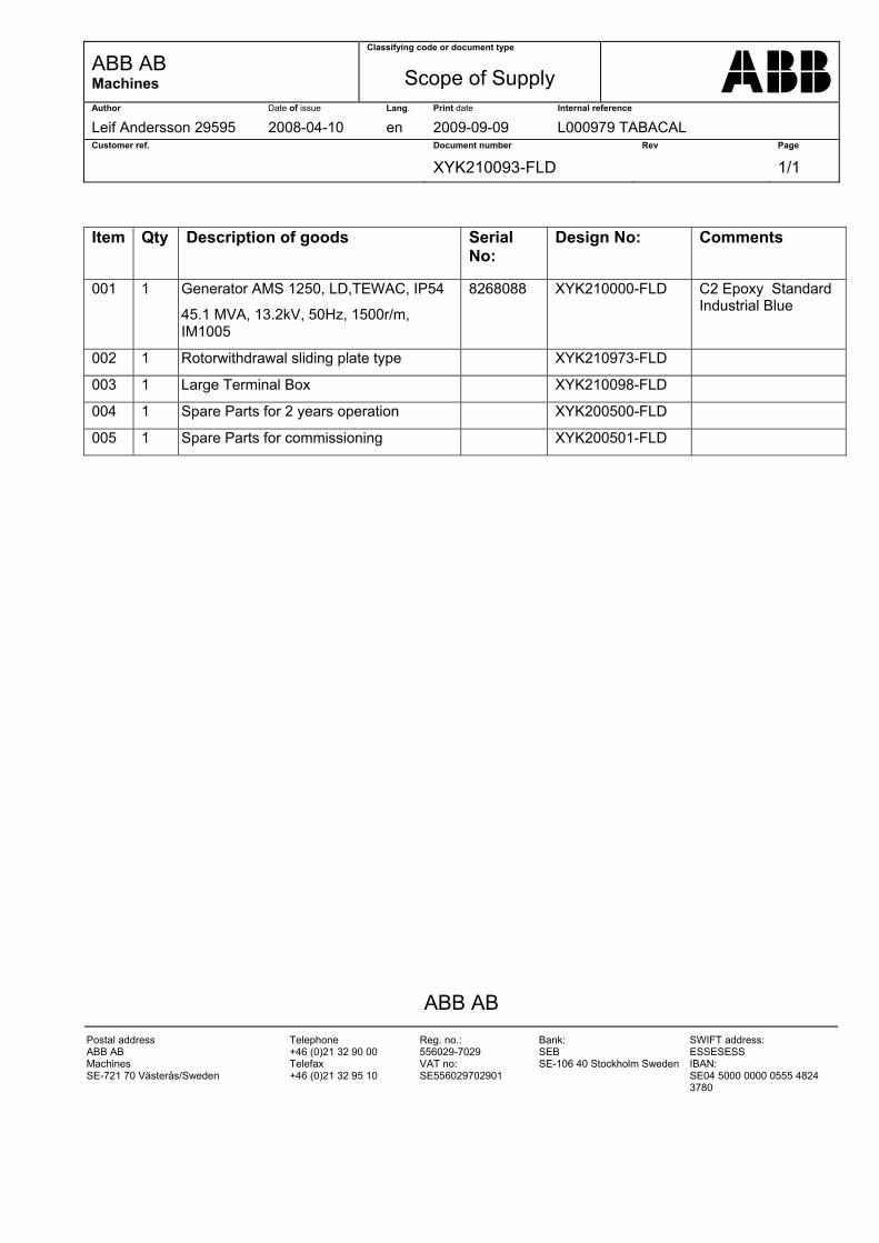
ABB AB Machines
Classifying code or document type
Scope of Supply
Author Date of issue Lang. Print date Internal reference
Leif Andersson 29595 2008-04-10 en 2009-09-09 L000979 TABACAL Customer ref. Document number Rev Page
XYK210093-FLD 1/1
ABB AB
Postal address ABB AB Machines SE-721 70 Västerås/Sweden
Telephone +46 (0)21 32 90 00 Telefax +46 (0)21 32 95 10
Reg. no.: 556029-7029 VAT no: SE556029702901
Bank: SEB SE-106 40 Stockholm Sweden
SWIFT address: ESSESESS IBAN: SE04 5000 0000 0555 4824 3780
Item Qty Description of goods Serial
No: Design No:
Comments
001 1 Generator AMS 1250, LD,TEWAC, IP54
45.1 MVA, 13.2kV, 50Hz, 1500r/m, IM1005
8268088 XYK210000-FLD C2 Epoxy Standard Industrial Blue
002 1 Rotorwithdrawal sliding plate type XYK210973-FLD
003 1 Large Terminal Box XYK210098-FLD
004 1 Spare Parts for 2 years operation XYK200500-FLD
005 1 Spare Parts for commissioning XYK200501-FLD
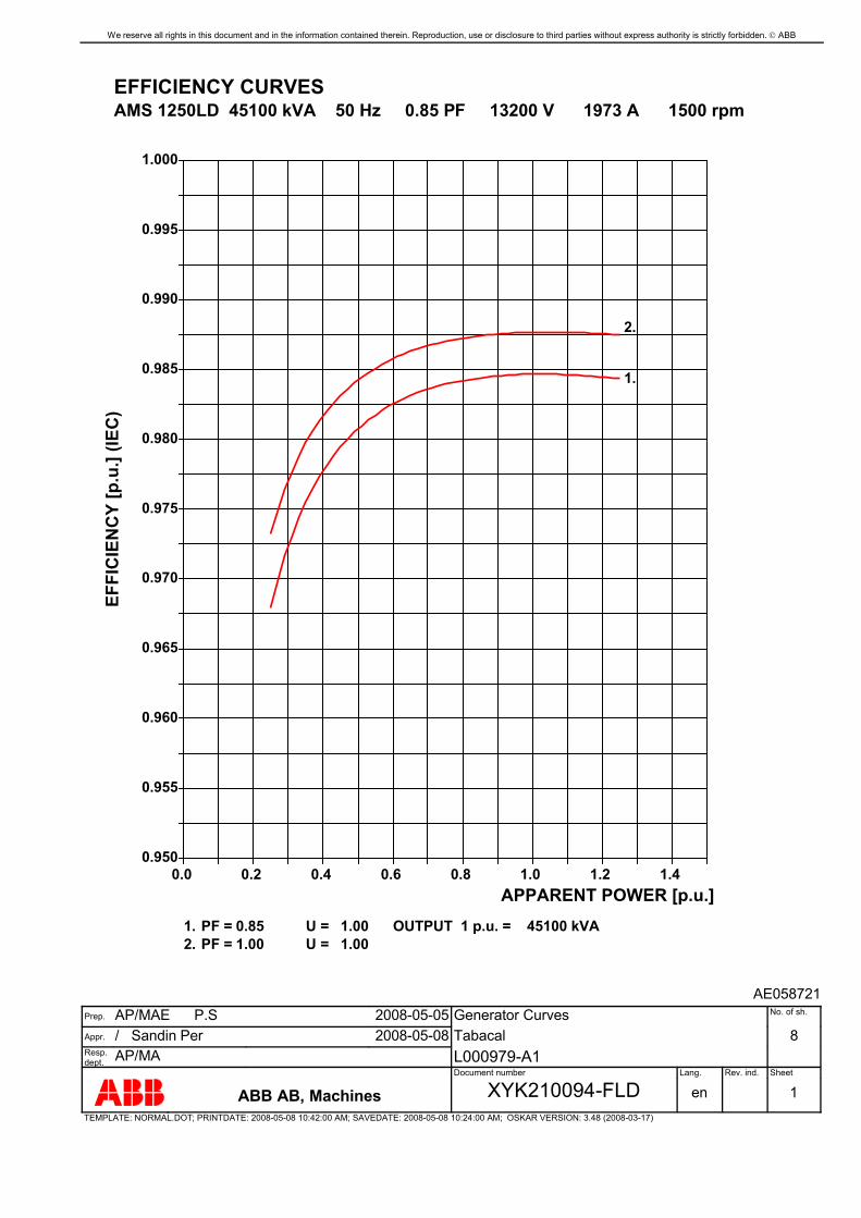
We reserve all rights in this document and in the information contained therein. Reproduction, use or disclosure to third parties without express authority is strictly forbidden. ABB
AE058721Prep. AP/MAE P.S 2008-05-05 Generator Curves No. of sh.
Appr. / Sandin Per 2008-05-08 Tabacal 8Resp. dept. AP/MA L000979-A1
Document number Lang. Rev. ind. Sheet
ABB AB, Machines XYK210094-FLD en 1TEMPLATE: NORMAL.DOT; PRINTDATE: 2008-05-08 10:42:00 AM; SAVEDATE: 2008-05-08 10:24:00 AM; OSKAR VERSION: 3.48 (2008-03-17)
EFFICIENCY CURVES AMS 1250LD 45100 kVA 50 Hz 0.85 PF 13200 V 1973 A 1500 rpm
OUTPUT 1 p.u. = 45100 kVA
1.000
0.995
0.990
0.985
0.980
0.975
0.970
0.965
0.960
0.955
0.950
EFFI
CIE
NC
Y [p
.u.]
(IEC
)
APPARENT POWER [p.u.] 1.41.21.00.80.60.40.20.0
1. PF = U = 0.85 1.00
1.
2. PF = U = 1.00 1.00
2.

We reserve all rights in this document and in the information contained therein. Reproduction, use or disclosure to third parties without express authority is strictly forbidden. ABB
Document number Lang. Rev. ind. Sheet
ABB AB, Machines XYK210094-FLD en 2TEMPLATE: NORMAL.DOT; PRINTDATE: 2008-05-08 10:42:00 AM; SAVEDATE: 2008-05-08 10:24:00 AM; OSKAR VERSION: 3.48 (2008-03-17)
SATURATION CURVES - A AMS 1250LD 45100 kVA 50 Hz 0.85 PF 13200 V 1973 A 1500 rpm
0.0
0.2
0.4
0.6
0.8
1.0
1.2
1.4
1.6
AR
MA
TUR
E-VO
LTA
GE
[p.u
.] A
ND
CU
RR
ENT
[p.u
.]
FIELD CURRENT [p.u.]3.22.82.42.01.61.20.80.40.0
1. 2.
1. OPEN -CIRCUIT SATURATION 2. SHORT-CIRCUIT SATURATION
ARMATURE VOLTAGEARMATURE CURRENTFIELD CURRENT
1 p.u. = 13200 V 1 p.u. = 1973 A 1 p.u. = 191 A

We reserve all rights in this document and in the information contained therein. Reproduction, use or disclosure to third parties without express authority is strictly forbidden. ABB
Document number Lang. Rev. ind. Sheet
ABB AB, Machines XYK210094-FLD en 3TEMPLATE: NORMAL.DOT; PRINTDATE: 2008-05-08 10:42:00 AM; SAVEDATE: 2008-05-08 10:24:00 AM; OSKAR VERSION: 3.48 (2008-03-17)
V-CURVES AMS 1250LD 45100 kVA 50 Hz 0.85 PF 13200 V 1973 A 1500 rpm
0.0
0.2
0.4
0.6
0.8
1.0
1.2
1.4
APP
AR
ENT
POW
ER [p
.u.]
FIELD CURRENT [p.u.]3.22.82.42.01.61.20.80.40.0
GENERATOR OUTPUT 1 p.u. = kVA 45100FIELD CURRENT 1 p.u. = A 191
UNDEREXCITED OVEREXCITED
+++ PRACTICAL STABILITY LIMIT - - - POWER FACTOR
ACTIVE OUTPUT
NOTE: P P N
P = Nominal active output N
--- = 1 IS EQUAL TO p.u. = 0.85
0.0
ACTIVE OUTPUT [p.u.] = 1. 0.00
1.
2. ACTIVE OUTPUT [p.u.] = 0.43
2.
3. ACTIVE OUTPUT [p.u.] = 0.85
3.
0.0
0.5 0.7 0.9 1.0 0.9
0.7
0.5
0.85
+ + + + + + + + + + + + + + + + + + + + + ++
++
+

We reserve all rights in this document and in the information contained therein. Reproduction, use or disclosure to third parties without express authority is strictly forbidden. ABB
Document number Lang. Rev. ind. Sheet
ABB AB, Machines XYK210094-FLD en 4TEMPLATE: NORMAL.DOT; PRINTDATE: 2008-05-08 10:42:00 AM; SAVEDATE: 2008-05-08 10:24:00 AM; OSKAR VERSION: 3.48 (2008-03-17)
CAPABILITY DIAGRAM AT COOLING WATER TEMPERATURE OF 30.0°C AMS 1250LD 45100 kVA 50 Hz 0.85 PF 13200 V 1973 A 1500 rpm
-1.0
-0.8
-0.6
-0.4
-0.2
-0.0
0.2
0.4
0.6
0.8
1.0
REA
CTI
VE P
OW
ER [p
.u.]
0.1 0.3 0.5 0.7 0.9 1.1 1.3ACTIVE POWER [p.u.]
UNDER- EXCITED
OVER- EXCITED
1.
2.
4.
BASE APPARENT POWER 1 p.u. = 45100 kVA1. STATOR HEATING LIMIT2. ROTOR HEATING LIMIT3. PRACTICAL STABILITY LIMIT
4. ZERO FIELD-CURRENT LIMIT5. CORE END HEATING LIMIT
0.50
0.70
0.90
0.90
0.70
0.50
0.85
3.
U = 1.005.

We reserve all rights in this document and in the information contained therein. Reproduction, use or disclosure to third parties without express authority is strictly forbidden. ABB
Document number Lang. Rev. ind. Sheet
ABB AB, Machines XYK210094-FLD en 5TEMPLATE: NORMAL.DOT; PRINTDATE: 2008-05-08 10:42:00 AM; SAVEDATE: 2008-05-08 10:24:00 AM; OSKAR VERSION: 3.48 (2008-03-17)
GENERATOR OVERLOAD CURVE AMS 1250LD 45100 kVA 50 Hz 0.85 PF 13200 V 1973 A 1500 rpm
4.0
3.6
3.2
2.8
2.4
2.0
1.6
1.2
0.8
0.4
0.0
STA
TOR
CU
RR
ENT
(I) [p
.u.]
TIME [S]70.060.050.040.030.020.010.00.0
IEC 60034-3 Clause 4.15
(I - 1) x t = 37.5 s 2
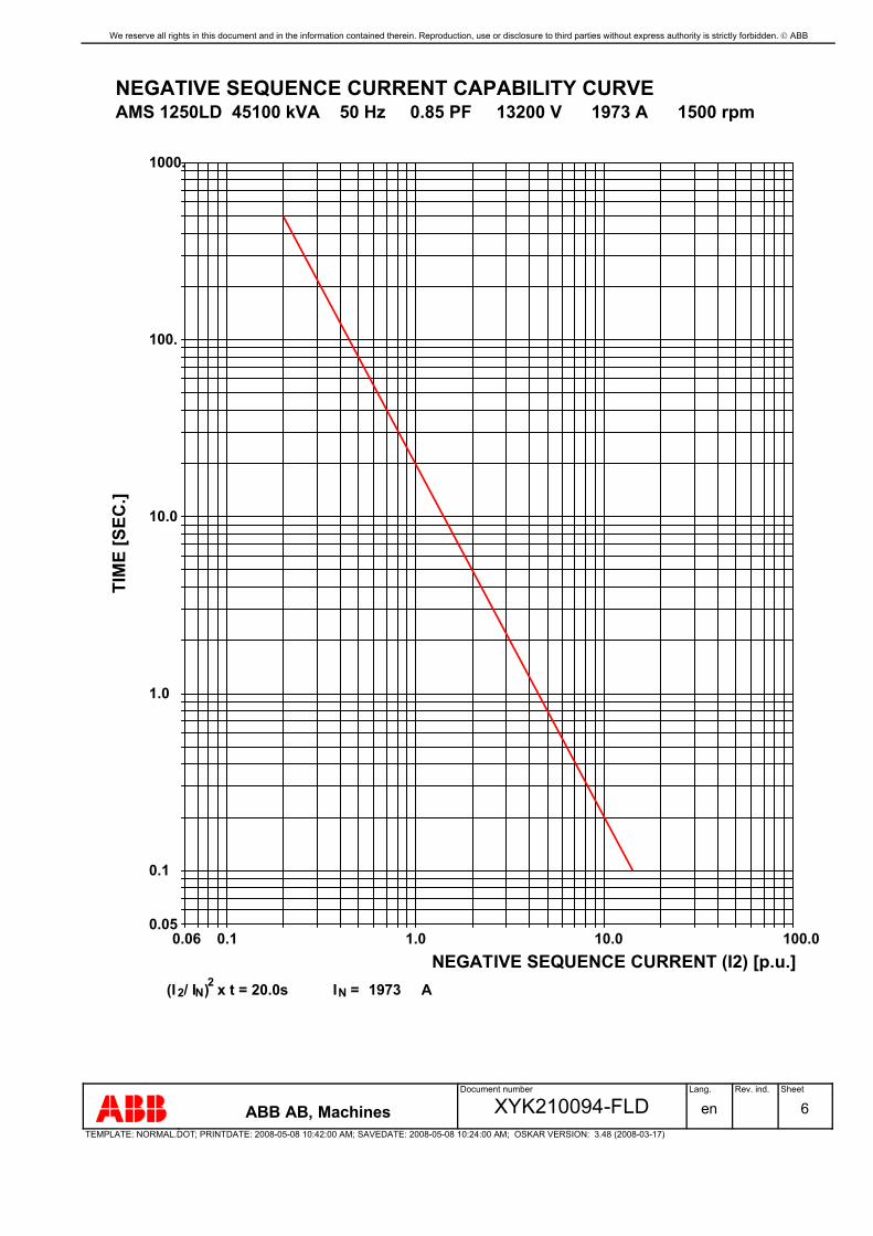
We reserve all rights in this document and in the information contained therein. Reproduction, use or disclosure to third parties without express authority is strictly forbidden. ABB
Document number Lang. Rev. ind. Sheet
ABB AB, Machines XYK210094-FLD en 6TEMPLATE: NORMAL.DOT; PRINTDATE: 2008-05-08 10:42:00 AM; SAVEDATE: 2008-05-08 10:24:00 AM; OSKAR VERSION: 3.48 (2008-03-17)
NEGATIVE SEQUENCE CURRENT CAPABILITY CURVE AMS 1250LD 45100 kVA 50 Hz 0.85 PF 13200 V 1973 A 1500 rpm
1000.
100.
10.0
1.0
0.1
0.05
TIM
E [S
EC.]
100.010.01.00.10.06NEGATIVE SEQUENCE CURRENT (I2) [p.u.]
(I / I ) x t = 2 N 2 20.0s I N = 1973 A

We reserve all rights in this document and in the information contained therein. Reproduction, use or disclosure to third parties without express authority is strictly forbidden. ABB
Document number Lang. Rev. ind. Sheet
ABB AB, Machines XYK210094-FLD en 7TEMPLATE: NORMAL.DOT; PRINTDATE: 2008-05-08 10:42:00 AM; SAVEDATE: 2008-05-08 10:24:00 AM; OSKAR VERSION: 3.48 (2008-03-17)
DECREMENT CURVE 3-PH. SHORT CIRCUIT AMS 1250LD 45100 kVA 50 Hz 0.85 PF 13200 V 1973 A 1500 rpm
10.09.08.07.06.0
5.0
4.0
3.0
2.0
1.00.90.80.70.6
0.5
0.4
0.3
0.2
0.1
CU
RR
ENT
(RM
S) [P
U]
TIME [S]1 pu = 1973. A
1.51.00.50.0

We reserve all rights in this document and in the information contained therein. Reproduction, use or disclosure to third parties without express authority is strictly forbidden. ABB
Document number Lang. Rev. ind. Sheet
ABB AB, Machines XYK210094-FLD en 8TEMPLATE: NORMAL.DOT; PRINTDATE: 2008-05-08 10:42:00 AM; SAVEDATE: 2008-05-08 10:24:00 AM; OSKAR VERSION: 3.48 (2008-03-17)
REVISIONRev.ind.
Page (P)Chapt.(C)
Description DateDept./Init.

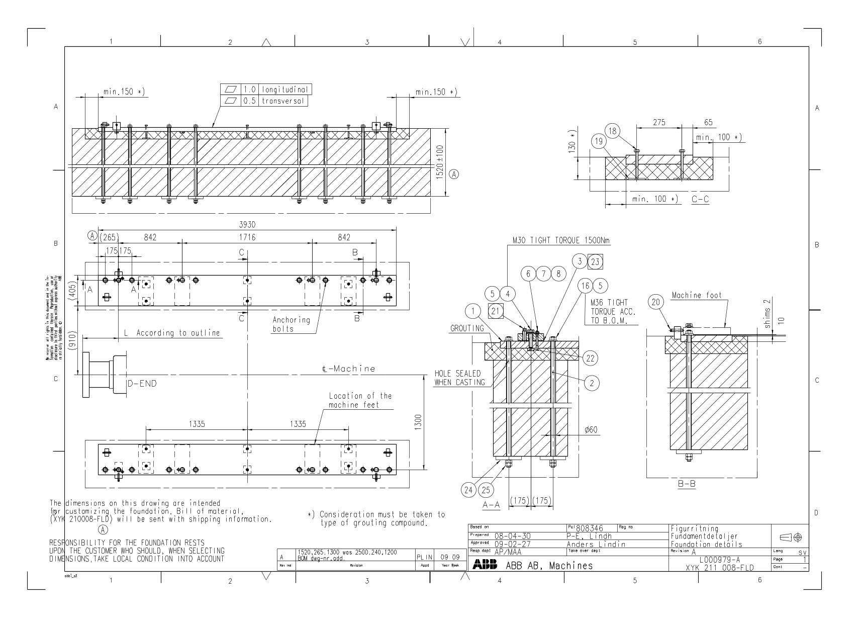
is st
rictly
for
bidde
n.
© A
BBdis
closu
re t
o th
ird p
artie
s with
out
expr
ess
auth
ority
infor
matio
n co
ntain
ed t
here
in. R
epro
duct
ion, u
se o
r We
rese
rve
all r
ights
in t
his d
ocum
ent
and
in th
e
B
21 3 4 5 6 7 8
1 2 3 4 5 6 7 8
A
D
E
F
C
A
B
C
D
E
FCont.PageLang.Rev.Document id.
Ref. designation
External doc. id.
Document kind
Title
Resp. (division/department)Work order id.
Approved
Prepared
Project nameProject no.
Customer
Based on
D041_A3
ReleasedCircuit diagram
Circuit diagramList of contents
B Gothilander2008‐08‐29
XYK 214 100‐FLD C enTabacalL000979
Siemens Ltd Brazil
MAE
P‐E Lindh2008‐12‐05
L000979‐A1 1 2
Project name: Tabacal
Customer: Siemens Ltd Brazil
Project no: L000979
1 List of contents2 Line connection, Surge arresters 3‐4 Voltage transformers 5 Machine 6 Current transformers Neutral side 7 Heaters 8 Temperature detectors in stator 9 Temperature detectors in bearings 10 Temperature detectors in air 11 Other detectors 12 Revision Notes

is st
rictly
for
bidde
n.
© A
BBdis
closu
re t
o th
ird p
artie
s with
out
expr
ess
auth
ority
infor
matio
n co
ntain
ed t
here
in. R
epro
duct
ion, u
se o
r We
rese
rve
all r
ights
in t
his d
ocum
ent
and
in th
e
B
21 3 4 5 6 7 8
1 2 3 4 5 6 7 8
A
D
E
F
C
A
B
C
D
E
FCont.PageLang.Rev.Document id.
Ref. designation
External doc. id.
Document kind
Title
Resp. (division/department)Work order id.
Approved
Prepared
Project nameProject no.
Customer
Based on
D041_A3
ReleasedCircuit diagram
Line connection, Surge arrestersB Gothilander2008‐06‐19
XYK 214 100‐FLD C enTabacalL000979
Siemens Ltd Brazil
MAE
P‐E Lindh2008‐12‐05
L000979‐A1 2 3
L1
L2
L3
U1 V1 W1
/3.A2
U1
/3.A2
V1
/3.A2
W1
+MTB
‐E1
‐E2
‐E3
‐C1
‐C2
‐C3
Clockwise rotationfacing shaft end
Earthing balls
Surge arresters17.5kV 10kA Cl.2
Capacitors0.25μF 15kV
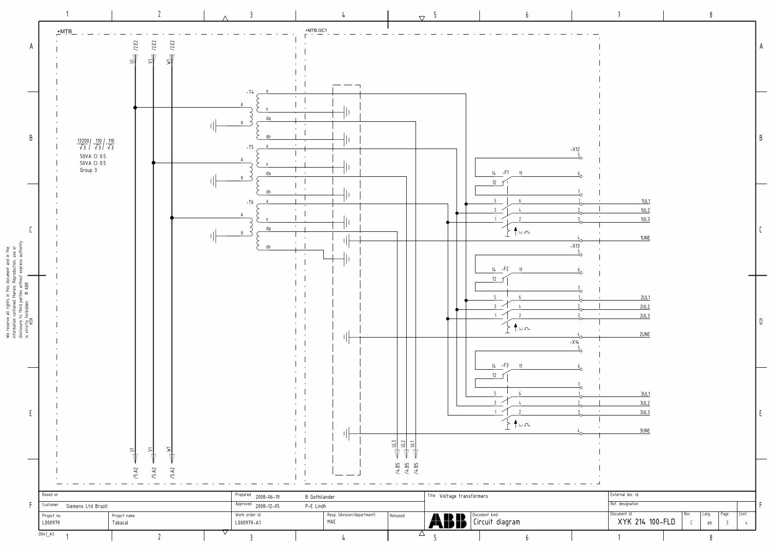
is st
rictly
for
bidde
n.
© A
BBdis
closu
re t
o th
ird p
artie
s with
out
expr
ess
auth
ority
infor
matio
n co
ntain
ed t
here
in. R
epro
duct
ion, u
se o
r We
rese
rve
all r
ights
in t
his d
ocum
ent
and
in th
e
B
21 3 4 5 6 7 8
1 2 3 4 5 6 7 8
A
D
E
F
C
A
B
C
D
E
FCont.PageLang.Rev.Document id.
Ref. designation
External doc. id.
Document kind
Title
Resp. (division/department)Work order id.
Approved
Prepared
Project nameProject no.
Customer
Based on
D041_A3
ReleasedCircuit diagram
Voltage transformersB Gothilander2008‐06‐19
XYK 214 100‐FLD C enTabacalL000979
Siemens Ltd Brazil
MAE
P‐E Lindh2008‐12‐05
L000979‐A1 3 4
/2.E2
U1
/2.E2
V1
/2.E2
W1
/5.A2
U1
/5.A2
V1
/5.A2
W1
‐T4
A
N
a
nda
dn
‐T5
A
N
a
nda
dn
‐T6
A
N
a
nda
dn
+MTB.GC1
I>/
1412
11‐F3
654321
I>/
1412
11‐F2
654321
I>/
1412
11‐F1
654321
3UNE
3UL33UL23UL1
2UNE
2UL32UL22UL1
1UNE
1UL31UL21UL1
/4.B5
UL1
/4.B5
UL2
/4.B5
UL3
‐X125
6
7123
4‐X13
5
6
7123
4‐X14
5
6
7123
4
+MTB
50VA Cl 0.550VA Cl 0.5
13200 110 110 √3 √3 √3
Group 3
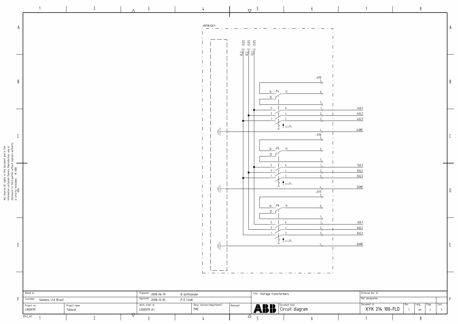
is st
rictly
for
bidde
n.
© A
BBdis
closu
re t
o th
ird p
artie
s with
out
expr
ess
auth
ority
infor
matio
n co
ntain
ed t
here
in. R
epro
duct
ion, u
se o
r We
rese
rve
all r
ights
in t
his d
ocum
ent
and
in th
e
B
21 3 4 5 6 7 8
1 2 3 4 5 6 7 8
A
D
E
F
C
A
B
C
D
E
FCont.PageLang.Rev.Document id.
Ref. designation
External doc. id.
Document kind
Title
Resp. (division/department)Work order id.
Approved
Prepared
Project nameProject no.
Customer
Based on
D041_A3
ReleasedCircuit diagram
Voltage transformersB Gothilander2008‐06‐19
XYK 214 100‐FLD C enTabacalL000979
Siemens Ltd Brazil
MAE
P‐E Lindh2008‐12‐05
L000979‐A1 4 5
4UL14UL24UL3
4UNE
5UL15UL25UL3
5UNE
6UL16UL26UL3
6UNE/3
.E5UL
3
/3.E5
UL2
/3.E5
UL1
214365
1412
11‐F4
I>/
214365
1412
11‐F5
I>/
214365
1412
11‐F6
I>/
+MTB.GC1
4
3217
6
‐X175
4
3217
6
‐X165
4
3217
6
‐X155
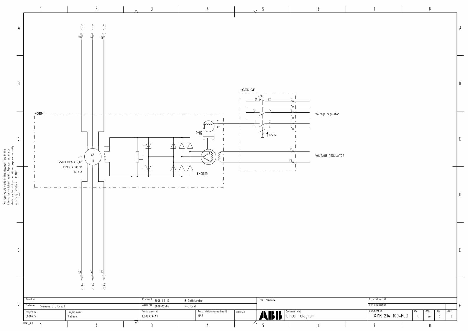
is st
rictly
for
bidde
n.
© A
BBdis
closu
re t
o th
ird p
artie
s with
out
expr
ess
auth
ority
infor
matio
n co
ntain
ed t
here
in. R
epro
duct
ion, u
se o
r We
rese
rve
all r
ights
in t
his d
ocum
ent
and
in th
e
B
21 3 4 5 6 7 8
1 2 3 4 5 6 7 8
A
D
E
F
C
A
B
C
D
E
FCont.PageLang.Rev.Document id.
Ref. designation
External doc. id.
Document kind
Title
Resp. (division/department)Work order id.
Approved
Prepared
Project nameProject no.
Customer
Based on
D041_A3
ReleasedCircuit diagram
MachineB Gothilander2008‐06‐19
XYK 214 100‐FLD C enTabacalL000979
Siemens Ltd Brazil
MAE
P‐E Lindh2008‐12‐05
L000979‐A1 5 6
/3.E2
U1
/3.E2
V1
/3.E2
W1
GS
1973 A13200 V 50 Hz
‐G145100 kVA x 0,85
EXCITER
F1
F2
PMG
A1A2
+GEN.GF
+GEN
/6.A2
U2
/6.A2
V2
/6.A2
W2
12
3456
2143
I>/
1413
‐F821 22
VOLTAGE REGULATOR
Voltage regulator

is st
rictly
for
bidde
n.
© A
BBdis
closu
re t
o th
ird p
artie
s with
out
expr
ess
auth
ority
infor
matio
n co
ntain
ed t
here
in. R
epro
duct
ion, u
se o
r We
rese
rve
all r
ights
in t
his d
ocum
ent
and
in th
e
B
21 3 4 5 6 7 8
1 2 3 4 5 6 7 8
A
D
E
F
C
A
B
C
D
E
FCont.PageLang.Rev.Document id.
Ref. designation
External doc. id.
Document kind
Title
Resp. (division/department)Work order id.
Approved
Prepared
Project nameProject no.
Customer
Based on
D041_A3
ReleasedCircuit diagram
Current transformersNeutral side
B Gothilander2008‐06‐19
XYK 214 100‐FLD C enTabacalL000979
Siemens Ltd Brazil
MAE
P‐E Lindh2008‐12‐05
L000979‐A1 6 7
/5.E2
U2
/5.E2
V2
/5.E2
W2
1s2
1s1‐T7
1s2
1s1‐T8
2s2
2s1‐T7
2s2
2s1‐T8
18171615141312
‐X211
2827
262524232221
1s2
1s1‐T9
2s2
2s1‐T9
U2 V2 W2
+MTB +MTB.GC1
10sek
‐R110A
1s2
1s1‐T10
‐X2414243
‐Q89
1 23
4 56
7 89
10 1112
13 1415
16 1718
+Q89.01
‐X21123
456
‐X2111
16
12131415
P1
P2
Generator protection
2500/5A25VA 10P20
2500/5A25VA Cl 0.5 FS7
100/1A2.5VA 10P10
Grounding switchManual operation
P2
P1
Earthing resistor 762Ω
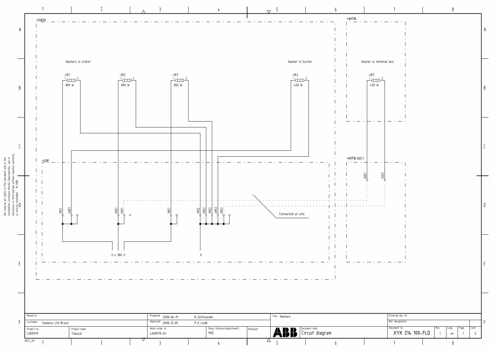
is st
rictly
for
bidde
n.
© A
BBdis
closu
re t
o th
ird p
artie
s with
out
expr
ess
auth
ority
infor
matio
n co
ntain
ed t
here
in. R
epro
duct
ion, u
se o
r We
rese
rve
all r
ights
in t
his d
ocum
ent
and
in th
e
B
21 3 4 5 6 7 8
1 2 3 4 5 6 7 8
A
D
E
F
C
A
B
C
D
E
FCont.PageLang.Rev.Document id.
Ref. designation
External doc. id.
Document kind
Title
Resp. (division/department)Work order id.
Approved
Prepared
Project nameProject no.
Customer
Based on
D041_A3
ReleasedCircuit diagram
HeatersB Gothilander2008‐06‐19
XYK 214 100‐FLD C enTabacalL000979
Siemens Ltd Brazil
MAE
P‐E Lindh2008‐12‐05
L000979‐A1 7 8
1HE1
1HE2
3HE2
4HE1
2HE1
4HE2
5HE1
2HE2
3HE1
5HE2
+MTB.GC1
+MTB
5HE1
5HE2
‐HE4
450 W
1 2‐HE1
800 W
1 2‐HE2
800 W
1 2‐HE3
800 W
1 2‐HE5
450 W
1 2
+GEN
+GE
Heater in ExciterHeaters in stator
3 x 380 V
Connected at site
Heater in terminal box
N

is st
rictly
for
bidde
n.
© A
BBdis
closu
re t
o th
ird p
artie
s with
out
expr
ess
auth
ority
infor
matio
n co
ntain
ed t
here
in. R
epro
duct
ion, u
se o
r We
rese
rve
all r
ights
in t
his d
ocum
ent
and
in th
e
B
21 3 4 5 6 7 8
1 2 3 4 5 6 7 8
A
D
E
F
C
A
B
C
D
E
FCont.PageLang.Rev.Document id.
Ref. designation
External doc. id.
Document kind
Title
Resp. (division/department)Work order id.
Approved
Prepared
Project nameProject no.
Customer
Based on
D041_A3
ReleasedCircuit diagram
Temperature detectors in statorB Gothilander2008‐06‐19
XYK 214 100‐FLD C enTabacalL000979
Siemens Ltd Brazil
MAE
P‐E Lindh2008‐12‐05
L000979‐A1 8 9
Whit
eWhit
e
Red
‐R4
Stator winding U
Whit
eWhit
e
Red
‐R2
Stator winding W
Whit
eWhit
e
Red
‐R3
Stator winding V
1R1
1R2
1R2
2R1
2R2
2R2
3R1
3R2
3R2
Whit
eWhit
e
Red
‐R5
Stator winding U
Whit
eWhit
e
Red
‐R6
Stator winding W
Whit
eWhit
e
Red
‐R7
Stator winding V
4R1
4R2
4R2
5R1
5R2
5R2
6R1
6R2
6R2
+GEN
+GA

is st
rictly
for
bidde
n.
© A
BBdis
closu
re t
o th
ird p
artie
s with
out
expr
ess
auth
ority
infor
matio
n co
ntain
ed t
here
in. R
epro
duct
ion, u
se o
r We
rese
rve
all r
ights
in t
his d
ocum
ent
and
in th
e
B
21 3 4 5 6 7 8
1 2 3 4 5 6 7 8
A
D
E
F
C
A
B
C
D
E
FCont.PageLang.Rev.Document id.
Ref. designation
External doc. id.
Document kind
Title
Resp. (division/department)Work order id.
Approved
Prepared
Project nameProject no.
Customer
Based on
D041_A3
ReleasedCircuit diagram
Temperature detectors in bearingsB Gothilander2008‐06‐19
XYK 214 100‐FLD C enTabacalL000979
Siemens Ltd Brazil
MAE
P‐E Lindh2008‐12‐05
L000979‐A1 9 10
‐R8
D‐End
‐R9
ND‐End
7R1
7R2
7R2
7R3
7R4
7R4
8R1
8R2
8R2
8R3
8R4
8R4
‐R10
D‐End
‐R11
ND‐End
9R1
9R2
9R2
9R3
9R4
9R4
10R1
10R2
10R2
10R3
10R4
10R4
+GEN
+GA
Bearing RTD's Bearing RTD's
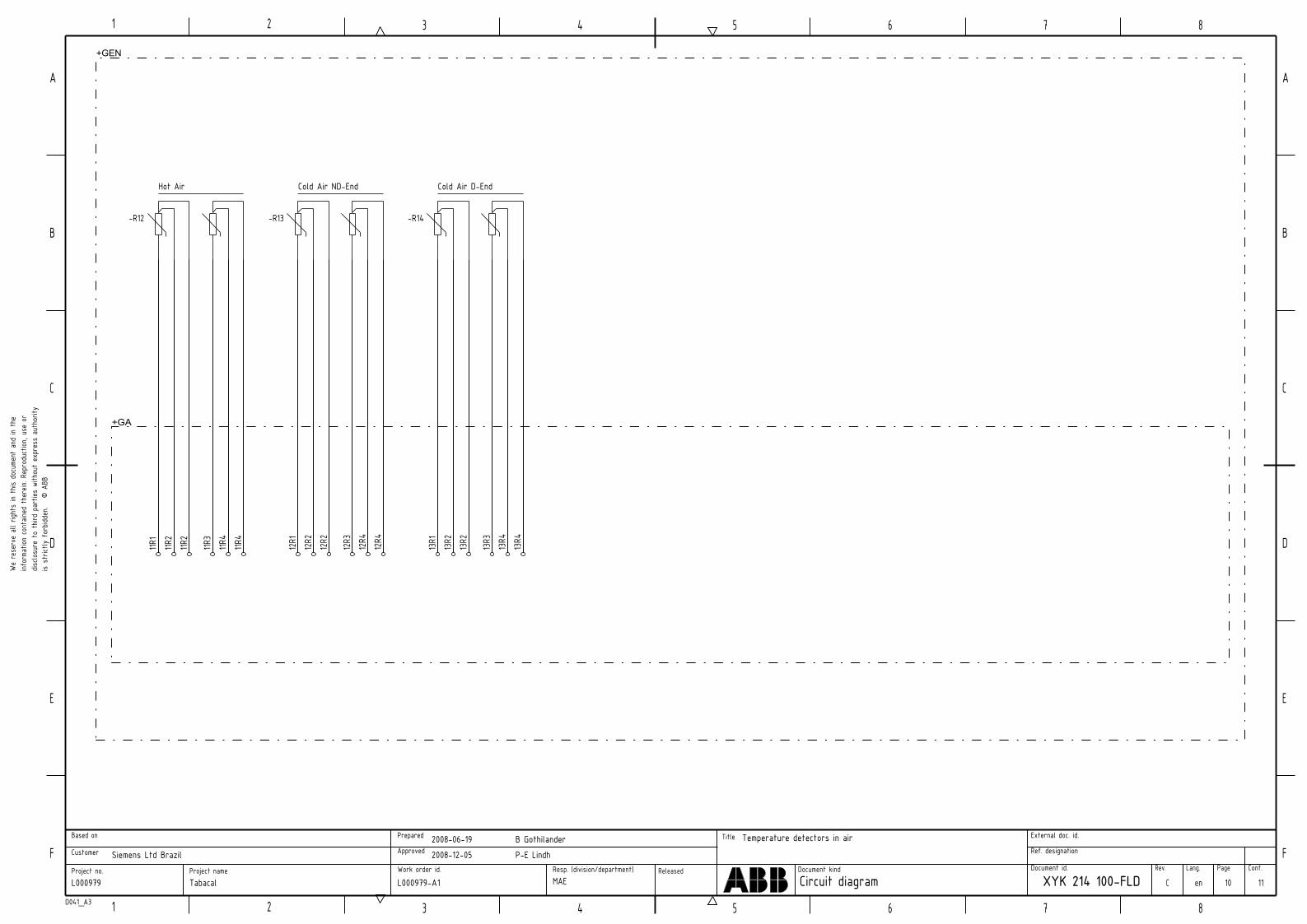
is st
rictly
for
bidde
n.
© A
BBdis
closu
re t
o th
ird p
artie
s with
out
expr
ess
auth
ority
infor
matio
n co
ntain
ed t
here
in. R
epro
duct
ion, u
se o
r We
rese
rve
all r
ights
in t
his d
ocum
ent
and
in th
e
B
21 3 4 5 6 7 8
1 2 3 4 5 6 7 8
A
D
E
F
C
A
B
C
D
E
FCont.PageLang.Rev.Document id.
Ref. designation
External doc. id.
Document kind
Title
Resp. (division/department)Work order id.
Approved
Prepared
Project nameProject no.
Customer
Based on
D041_A3
ReleasedCircuit diagram
Temperature detectors in airB Gothilander2008‐06‐19
XYK 214 100‐FLD C enTabacalL000979
Siemens Ltd Brazil
MAE
P‐E Lindh2008‐12‐05
L000979‐A1 10 11
‐R12
Hot Air
11R1
11R2
11R2
11R3
11R4
11R4
‐R13
Cold Air ND‐End
12R1
12R2
12R2
12R3
12R4
12R4
‐R14
Cold Air D‐End
13R1
13R2
13R2
13R3
13R4
13R4
+GEN
+GA
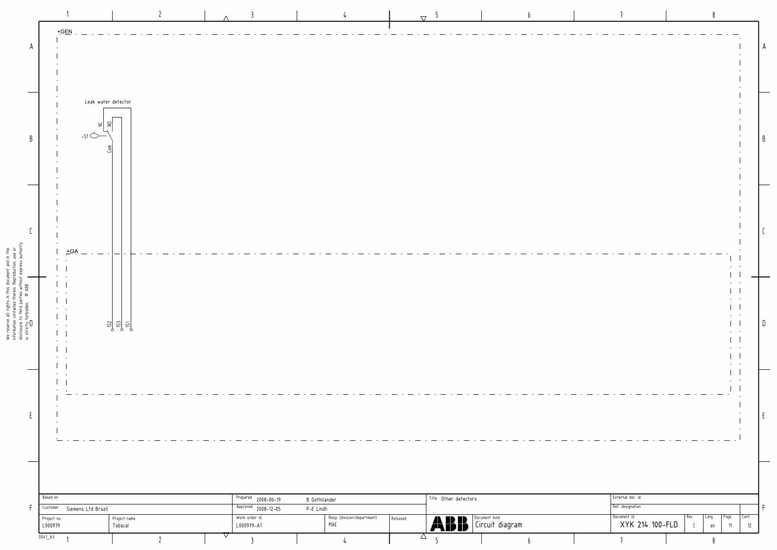
is st
rictly
for
bidde
n.
© A
BBdis
closu
re t
o th
ird p
artie
s with
out
expr
ess
auth
ority
infor
matio
n co
ntain
ed t
here
in. R
epro
duct
ion, u
se o
r We
rese
rve
all r
ights
in t
his d
ocum
ent
and
in th
e
B
21 3 4 5 6 7 8
1 2 3 4 5 6 7 8
A
D
E
F
C
A
B
C
D
E
FCont.PageLang.Rev.Document id.
Ref. designation
External doc. id.
Document kind
Title
Resp. (division/department)Work order id.
Approved
Prepared
Project nameProject no.
Customer
Based on
D041_A3
ReleasedCircuit diagram
Other detectorsB Gothilander2008‐06‐19
XYK 214 100‐FLD C enTabacalL000979
Siemens Ltd Brazil
MAE
P‐E Lindh2008‐12‐05
L000979‐A1 11 12
‐S1
NC NOCo
m1S
21S
31S
1
+GEN
+GA
Leak water detector

is st
rictly
for
bidde
n.
© A
BBdis
closu
re t
o th
ird p
artie
s with
out
expr
ess
auth
ority
infor
matio
n co
ntain
ed t
here
in. R
epro
duct
ion, u
se o
r We
rese
rve
all r
ights
in t
his d
ocum
ent
and
in th
e
B
21 3 4 5 6 7 8
1 2 3 4 5 6 7 8
A
D
E
F
C
A
B
C
D
E
FCont.PageLang.Rev.Document id.
Ref. designation
External doc. id.
Document kind
Title
Resp. (division/department)Work order id.
Approved
Prepared
Project nameProject no.
Customer
Based on
D041_A3
ReleasedCircuit diagram
Revision NotesB Gothilander2008‐06‐19
XYK 214 100‐FLD C enTabacalL000979
Siemens Ltd Brazil
MAE
P‐E Lindh2008‐12‐05
L000979‐A1 12
REVISIONRev.ind. Page Description Date/Init.
A 2,3,6 Changed device designations, value on earthing resistor, transformer ratios. 080829/RP
B 8‐10 Changed terminal designations 081104/RP
C 5666
Changed auxiliary contact of MCB F8 from SPDT to 1NO/1NCAdded auxiliary contacts to Q89 Changed CT ratio from 10/1A to 100/1AChanged earthing resistor from 760Ω to 762Ω
081205/BG