Generation and Computerized Simulation of … and Computerized Simulation of Meshing and ......
76
NASA Contractor Report 4644 Army Research Laboratory Contractor Report ARL-CR-221 Generation and Computerized Simulation of Meshing and Contact of Modified Involute Helical Gears Faydor L. Litvin, Ningxin Chen, and Jian Lu University of Illinois at Chicago Chicago, Illinois Prepared for Propulsion Directorate U.S. Army Aviation Systems Command and Lewis Research Center under Grant NAG3-1469 National Aeronautics and Space Administration Office of Management Scientific and Technical Information Program 1995 https://ntrs.nasa.gov/search.jsp?R=19950017975 2018-06-01T07:46:46+00:00Z
Transcript of Generation and Computerized Simulation of … and Computerized Simulation of Meshing and ......

NASA
Contractor Report 4644
Army Research Laboratory
Contractor Report ARL-CR-221
Generation and Computerized Simulation of
Meshing and Contact of ModifiedInvolute Helical Gears
Faydor L. Litvin, Ningxin Chen, and Jian LuUniversity of Illinois at ChicagoChicago, Illinois
Prepared for
Propulsion Directorate
U.S. Army Aviation Systems Commandand
Lewis Research Center
under Grant NAG3-1469
National Aeronautics and
Space Administration
Office of Management
Scientific and TechnicalInformation Program
1995
https://ntrs.nasa.gov/search.jsp?R=19950017975 2018-06-01T07:46:46+00:00Z


GENERATION AND COMPUTERIZED SIMULATION OF MESHING AND
CONTACT OF MODIFIED. INVOLUTE HELICAL GEARS
by
Faydor L. Litvin
Principal Investigator
Ningxin Chen and Jian Lu
Research Associates
University of Illinois at Chicago, Chicago, IL
Abstract
The design and generation of modified involute helical gears that have a localized and
stable bearing contact, and reduced noise and vibration characteristics are described. The
localization of the bearing contact is achieved by the mismatch of the two generating surfaces
that are used for generation of the pinion and the gear. The reduction of noise and vibration
will be achieved by application of a parabolic function of transmission errors that is able to
absorb the almost linear function of transmission errors caused by gear misalignment. The
meshing and contact of misaligned gear drives can be analyzed by application of computer
programs that have been developed. The computations confirmed the effectiveness of the
proposed modification of the gear geometry. A numerical example that illustrates the devel-
oped theory is provided.
a
ae
b
E,o
E.
E,,
m21
nr
P,_
ri
ri_r_
r_i)
ltr _lr
v(_)
v(iJ)
&
5
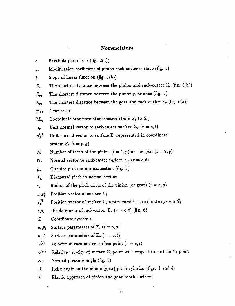
Nomenclature
Parabola parameter (fig. 2(a))
Modification coefficient of pinion rack-cutter surface (fig. 5)
Slope of linear function (fig. l(b))
The shortest distance between the pinion and rack-cutter E¢ (fig. 6(b))
The shortest distance between the pinion-gear axes (fig. 7)
The shortest distance between the gear and rack-cutter Zt (fig. 6(a))
Gear ratio
Coordinate transformation matrix (from Sj to Si)
Unit normal vector to rack-cutter surface Z_ (r = c, _)
Unit normal vector to surface Zi represented in coordinate
system S/(i = p, g)
Number of t&th of the pinion (i = 1,p) or the gear (i = 2,g)
Normal vector to rack-cutter surface Z, (r = c, t)
Circular pitch in normal section (fig. 3)
Diametral pitch in normal section
Radius of the pitch circle of the pinion (or gear) (i = p, g)
Position vector of surface Ei
Position vector of surface Zi represented in coordinate system S!
Displacement of rack-cutter E_ (r - c, t) (fig. 6)
Coordinate system i
Surface parameters of Ei (i = p, g)
Surface parameters of _, (r = c, t)
Velocity of rack-cutter surface point (r - c, £)
Relative velocity of surface Ei point with respect to surface Ej point
Normal pressure angle (fig. 3)
Helix angle on the pinion (gear) pitch cylinder (figs. 3 and 4)
Elastic approach of pinion and gear tooth surfaces
2

_E
AAo
_q
_o
E_
• _)pc
Change of center distance
Change of pinion lead angle on the pitch cylinder
Displacement of contact point caused by rnisalignment
Misalignment angle formed by crossed gear axes (fig. 8(a))
Misalignment angle formed by intersected gear axes (fig. 8(b))
Transmission error (fig. 2)
Vector of the angle of compensating turn of gear 2
Lead angle on pinion pitch cylinder
Pinion (i = p) and gear (i = g) tooth surfaces
Rzr_k-cutter surfaces (r = c,_)
Rotation angle of gear i (i - 1,2, p, g) (figs. 2 and 7)
Rotation angle of gear being in mesh with the rack-cutter E_ (fig. 6(a))
Rotation angle of pinion being in mesh with the rack-cutter Zc (fig- 6(b))
3

1. Introduction
Conventional helical involute gears are designed for transformation of rotation between
parallel axes. Theoretically, the gear tooth surfaces are in line tangency at every instant,
along a straight line that is a tangent to the helix on the gear base cyfinder. However, the
line contact of gear tooth surfaces can be reafized only for an ideal gear drive. In reality, the
crossing of axes of rotation (instead of being parallel) and errors of lead angle result in the
so-caUed edge contact, as a specific instantaneous point contact caused by curve-to-surface
tangency. Here, the contacting curve is the edge of the tooth surface of one of the mating
gears and the contacting surface is the tooth surface of the other one.
Trying to avoid the edge contact, the manufacturers of helical gears use various methods
of crowning (deviation) of the theoretical gear tooth surfaces. However, the applied methods
of crowning have not been complemented with the analysis of transmission errors caused
by misafignment. Our investigation shows that improper crowning may avoid edge contact
but cannot avoid the appearance of transmission errors of the shape shown in fig. 1. The
function of such transmission errors is piecewise, almost linear, and has the frequency equal
to the cycle of meshing of one pair of teeth. The above mentioned transmission errors cause
high vibration and noise and therefore such transmission errors must be avoided. This can
be achieved by application of computer numerically controlled (CNC) machines that have
opened new perspectives for generation of gear tooth surfaces with improved topology.
The intent of this paper is to describe a modified topology of low-noise involute hefical
gears that satisfies the following requirements:
(1) The noise and vibration of hetical gears are reduced substantially by application of a
predesigned function of transmission errors of a parabolic type (fig. 2). Such a function can
absorb (see below) an almost linear function of transmission errors shown in fig. 1.
(2) The bearing contact is localized. Theoretically, the tooth surfaces are in tangency at
every instant at a point instead of a line. The contact of gear tooth surfaces at every instant
4
is spread over an elliptical area due to elastic deformation of gear teeth. The dimension of
the instantaneous contact ellipse can be controlled by choosing proper design parameters.
(3) The proposed gear tooth surfaces can be generated by two rack-cutters designed for
generation of the pinion and gear, respectively. A nonlinear transmission function in the
process for gear generation must be provided and this can be accomplished by application of
the CNC machine. A linear transmission function is provided in the process for the pinion
generation.
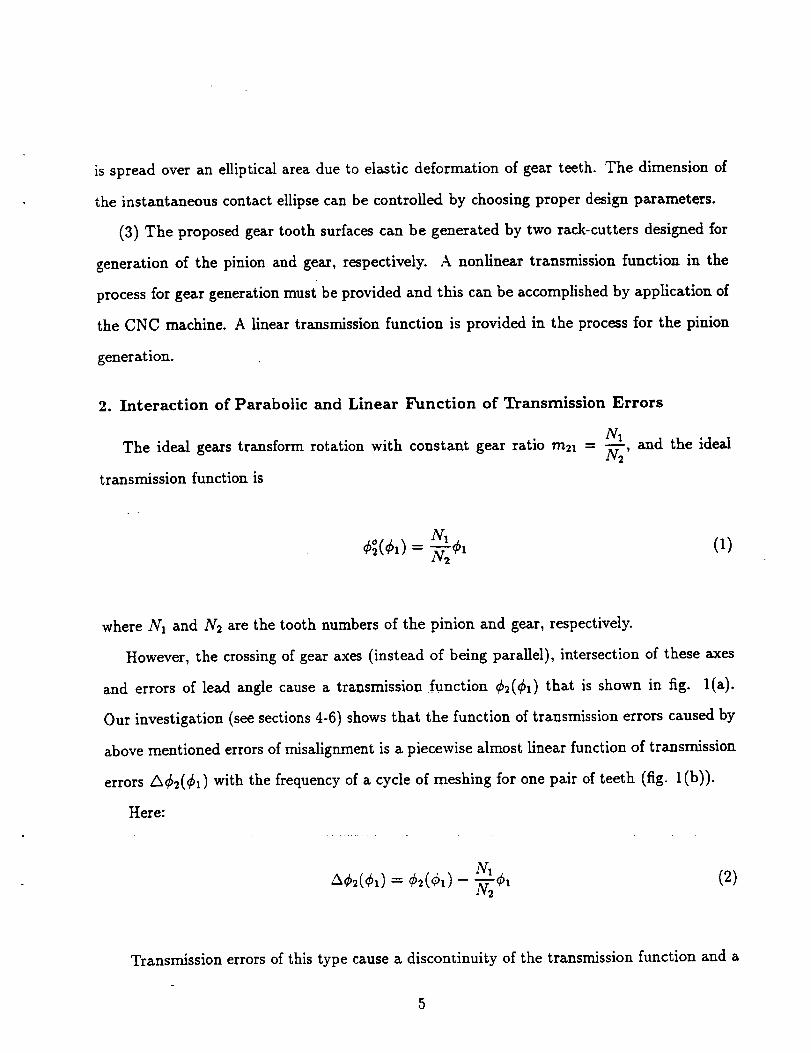
2. Interaction of Parabolic and Linear Function of Transmission Errors
The ideal gears transform rotation with constant gear ratio m21 = _,and the ideal
transmission function is
¢_(¢1) = _-_2¢x (1)
where N1 and N2 are the tooth numbers of the pinion and gear, respectively.
However, the crossing of gear axes (instead of being parallel), intersection of these axes
and errors of lead angle cause a transmission function ¢2(¢1) that is shown in fig. l(a).
Our investigation (see sections 4-6) shows that the function of transmission errors caused by
above mentioned errors of misalignment is a piecewise almost linear function of transmission
errors A¢2(¢x) with the frequency of a cycle of meshing for one pair of teeth (fig. l(b)).
Here:
NIA¢2(¢,) = -
1v2
(2)
Transmission errors of this type cause a discontinuity of the transmission function and a

big jump of the angular velocity of the driven gear at transfer points (when one pair of teeth
is changed to another one). Therefore, vibration and noise become inevitable.
It was proven [1,2,4] that a predesigned parabolic function of transmission errors in-
teracting with a linear function will become a parabolic function with the same parabola
parameter. A parabolic function of transmission errors is much more preferable than a lin-
ear function since the transmission function will be a continuous one, the jump of angular
velocity of the driven gear and the stroke at the transfer point will be substantially reduced.
Fig. 2(a) shows the sum of two functions of transmission errors
= + = b¢1- (3)
The first one, _¢(2_)(¢1), is caused by misalignment. The second one, A¢_2)(¢1), is a
predesigned parabolic function which exists even if misalignment does not appear. It is easy
to verify that equation (3) represents in the new coordinate system (A¢2, ¢1) the parabolic
function (fig. 2(b)) that is designated as
= (4)
The parabola parameter a in equations (3) and (4) is the same. Axes of coordinate
system (/k_b2, ¢1) and (A¢2, ¢1) are parallel but the origins are different. The coordinate
transformation from (/k¢2, ¢1) to (A¢2, ¢1) is represented with the following equations
b2 b
A¢2 = A¢2 - 4-_' ¢1 = ¢_ - 2-"_ (5)
6

The differencebetweenfunctions A62((_1) and A_,2(_bl) is the location of the couple of
points (A, B) and the respective points (A*, B*) (fig. 2(a)). The symmetrical location of
(A,B) is turned into the asymmetrical location of (A*, B'). However, the interaction of
several functions A_k2(_bl) determined for several tooth surfaces being in mesh may provide
a symmetrical parabofic function of transmission errors as shown in fig. 2(b). This can be
achieved if the parabohc function A¢h(qtx) will be predesigned in the area (fig. 2(a))
27r
- > + 2c (6)llv
b
where c = 2"a" Requirement (6), if observed, enables to provide a continuous function2_r
A_(¢I) for the range of _ where N1 is the pinion tooth number. It will be shown below
(see sections 5 and 6) that functions of transmission errors caused by angular errors (such
as the crossing and intersection of the axes of rotation, error of the lead angles) are indeed
piecewise linear functions, and the coefficient b can be determined "knowing the angular error
caused by misalignment and the design parameters of the gear drive.
3. Surfaces of Rack-Cutters
The imaginary process of generation of conjugate tooth surfaces is based on application
of two rack-cutters that are provided respectively by a plane Et and a cylindrical surface Ec
that differs slightly from plane r,t (see fig. 3). The rack-cutter surfaces Zt and Zc are rigidly
connected each to other in the process of the imaginary generation, and they are in tangency
along a straight line, Obzs (fig. 5). This line and the parallel axes of the gears form angle
_o, that is equal to the helix angle on the pinion (gear) pitch cylinder. The normal sections
of the rack-cutters are shown in figs. 3 and 5. Rack-cutter surface Zc generates the pinion
tooth surface Zp, and the rack-cutter surface Et generates the gear tooth surface Zg.

Gear Rack-Cutters Et
Using figs. 3, 4 and 5, we represent the transformation matrix from system S_ to S_
(r = c, t) and Sb to S_ as follows
M_o
1 0 0 0
0 cos_o sinf_o 0
0 -sin_o cOS_o 0
0 0 0 1
(7)
Mab
cos ao - sina o 0 -d_ cos ao
sinao cosao 0 a=-dpsinao
0 0 1 0
0 0 0 1
(8)
M_.b "-
cos ao - sin C_o 0 -dp cos ao
sin ao cos/3o cos C_ocos _o sin _o (a,_ - dp sin C_o)cos _o
- sin ao sin _ - cos ao sin _o cos/5o -(am - dp sin ao) sin/_o
0 0 0 1
(9)
Here C_oand/3o are the normal pressure angle and the helix angle of the rack-cutter; a=
is the half of the tooth width of the rack-cutter on middle line m - m (fig. 3), where
(10)an t --

and P,_ is the normal diametral pitch of the rack-cutter, dp is the distance between middle
line m - m of the rack-cutter and the origin Ob along axis zb, fig. 5. Parameter dp can be
controlled to adjust the location of the contact path on the gear tooth surface.
Surface Et of the gear rack-cutter is a plane that is represented in S_ as
r_b)--[ ut 0 lt] T (11)
where (ut, ls) are the surface parameters.
Rack-cutter surface Et is represented in coordinate system St by the matrix equation
rt(ut, It) --M, br_b) (12)
Equations (9), (11) and (12)yield
rt --
(u, - d. ) cos'_o
[(u, - d.) sin,_o+ ,,._]co__o+ l, sinao
- [(u, - alp)sin ao + a.._]sin Bo+ l, cos/_o
(13)
The unit normal to Et is represented in St by equations
Nt 0rt 0rt
n,= N, = 01--7× (14)
that yield

nt- [-sinao cOSaoCOS_o cOS_osinBo (15)
Pinion Rack-Cutter Surface Ec
Rack-cutter Ec generates the pinion. The normal section of rack-cutter surface E_ (fig. 5)
is a parabolic curve. We remind that the normal section of rack-cutter surface Zt is a straight
line directed along axis zb in fig. 5. The parabolic curve is in tangency with the zb-axis at
point N(Ob). Rack-cutter surfaces Z¢ and Zt are in tangency along a straight line that is
parallel to axes z_ and zb and passes through point O_ that coincides with point N. The
deviation of the parabolic curve from the zb-axis affects the dimensions of the instantaneous
contact eUipse.
Rack-cutter surface E¢ is represented in S_ as follows
2 Ic ]Tr_b)-_ Uc --acUc (16)
where a. is coefficient of the parabohc normal section, and (uc, 1_) are the surface parameters
of Z_.
Rack-cutter surface Ec is represented in coordinate system Sc by the matrix equation
r¢(uc, l_) -- M_r_ s) (17)
Equations (9), (16) and (17) yield
10
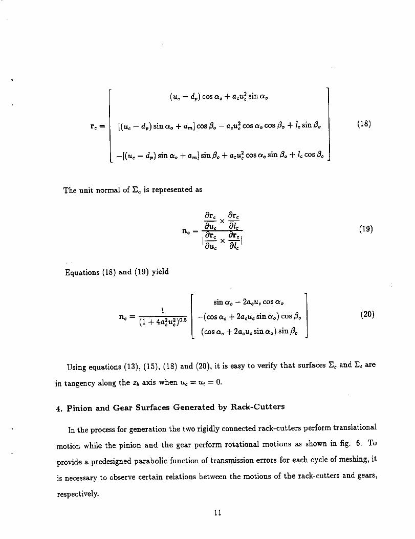
r c
2 sin ao(u_ - dp) cos ao + a_u_
[(uc- d.) sin _o + am] cos8o - acu 2 cos ao cos Bo + Icsin 8o
-[(uc- @) sin ao + a,_] sin _o + acu_ cos ao sin _o + l_ cos _o
(18)
The unit normal of E_ is represented as
n¢
8re 8reX
8u, ,.81_
io o 8,°8,,° x
(19)
Equations (18) and (19) yield
nc
1
2205(1 + 4acu,) •
sinao - 2acuc cos ao
-(cos ao + 2a¢u_ sinao) cos 8o
(cos ao + 2a_u_ sin ero) sin/3o
(20)
Using equations (13), (15), (18) and (20), it is easy to verify that surfaces Z_ and Zt are
in tangency along the z_ axis when u, = ut = O.
4. Pinion and Gear Surfaces Generated by Rack-Cutters
In the process for generation the two rigidly connected rack-cutters perform translational
motion while the pinion and the gear perform rotational motions as shown in fig. 6. To
provide a predesigned parabolic function of transmission errors for each cycle of meshing, it
is necessary to observe certain relations between the motions of the rack-cutters and gears,
respectively.
11

The angle@_of pinion rotation and the displacements¢ of rack-cutter Ec are related by
the following linear function
g, = s__ (21)rlo
Here: rp is the radius of the pinion pitch cylinder.
The angle _gt of gear rotation and the displacement st of rack-cutter St are related as
follows
(22)
Here: Np and N 9 are the tooth numbers of the pinion and gear, respectively, and _(o) is
the initial position angle of the gear for the modification gear rotation.
Equation of Meshing between Rack-Cutter Ec and Pinion _v
The equation of meshing between rack-cutter Ec and the pinion tooth surface Ep is
represented as
f(uc, l_, _bp_) = N(_c)- v_ "r) = 0 (23)
where _bvc is the angle of rotation of the pinion in the process for generation. The normal
N_ ") to E_ in S_ can be obtained by equation (20), and the relative velocity of the pinion
with respect to E_ may be represented as ....................
12

v_po)= _,_ × (r_ + ro)- ( 0 Td¢_c (24)_,0)
Here: 1_ = (_-O'_)c = (rp rpCpc 0) T, rp - Epc is the radius of the pitch cylinder of
the pinion (fig. 6), w(_P)= _P)( 0 0 1 )T.
Substitution of equations (19) and (24) into (23), yields the following equation of meshing
between Ep and E_
f(uc, Ic, Cpc) = lc sin & + rpCp, + a,,_ cos/3o +[(u, - d_) + 2a_u_] cos _o
sinao - 2acu¢ cos <_o--0 (25)
Surface of Pinion _._
In the process of generation of pinion surface, rack-cutter E¢ performs uniform translation
and the workpiece performs uniform rotation (fig. 6(b)). The transformation matrix from
system S_ to Sp can be represented as
cos Cp= sin ¢_ 0 rp cos Cp_ + rpCpc sin ¢_
- sin ¢_c cos Cp_ 0 -rp sin ¢p¢ + rpCp= cos Cp_
0 0 1 0
0 0 0 1
(26)
Pinion surface E_ in system Sp is represented as
rp(u_, I=, Cpc) = Mp=r=
l== -. si_/---_a_-_:c---_sao cos#o+ rp¢,=+ a_ cos#o}/ sin#o
(27)
13

Substituting equation (26) into (27), we obtain equation of Ep as
(28)
Equation of Meshing between Rack-Cutter Et and Gear Zg
The equation of meshing between rack-cutter Zt and the gear tooth surface Eg isrepre-
sented as
f(ut, It, ¢,t) -- n_ ')" v_ 't) = 0 (29)
where Cgt is the angle of rotation of the gear in the process for generation. The unit normal
n_ _) to Zlt in St is represented by equation (15), and v_gt} is the relative velocity of the gear
with respect to rack-cutter Zt.
We recall that the rack-cutter Zt performs translation with constant velocity, but the
gear performs rotation with variable angular velocity that is represented as (see equation
(22))
]T d_pc_9_ = 0 0 -[-_- 2.(¢,o- _0_)1 (30)
The relative velocity v_ gt) is represented as
g_(31)
14
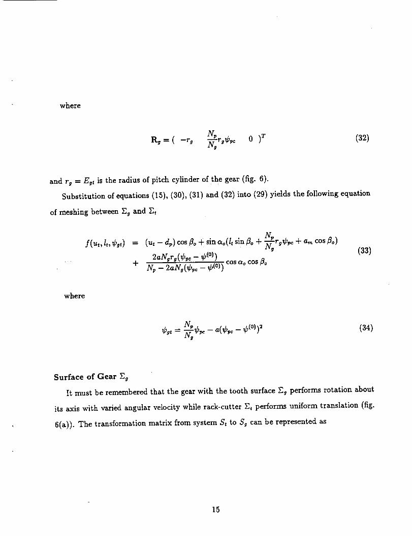
where
Sg= ( -rg _rgCpc 0 (32)
and rg = Eg_ isthe radius of pitch cylinder of the gear (fig.6).
Substitution of equations (15),(30),(31) and (32) into (29) yieldsthe following equation
of meshing between Eg and Zt
f(ut,It,¢9t) = (ut - dp) cos/Bo+ sinao(Itsin8o + _'.rgCw + a_ cos/3o)
" + cos ao cos 8oN, - 2agA_,._- _(o))
(33)
where
N,¢,, = __¢_ _ _(¢,o_ ¢(0))2.LYg
(34)
Surface of Gear Eg
It must be remembered that the gear with the tooth surface E, performs rotation about
its axis with varied angular velocity while rack-cutter Et performs uniform translation (fig.
6(a)). The transformation matrix from system St to Sg can be represented as
15

M9 t --
IV_ •
- cos ¢9, sin Cgt 0 rg cos Cgt + r9 _'_¢w sm ¢_t
sin ¢9t - cos Cgt 0 rg sin,_gt - rg_aaCw cos ¢9,
0 0 1 0
0 0 0 1
(35)
Gear tooth surface _g in system 5'9 can be represented as
rg(u,, lt, Cgt) = Mg,rt
cot& N. 1Z,= -{(.,- a_)_._--_--+ (w_¢_o + ._ cos0o)sin/3oslna o iv#
(36)
2aNgrg(¢_c- ¢(o))N_- 2aN.(¢_o- ¢(0))cot_ocot_o}
The derivation of equation (36) is based on transformation of equations (33) and (34).
Equations (35) and (36) enable to represent the gear tooth surface in two-parameter form
as follows
r_(_,, ¢_,) = rg(_, e_) (37)
5. Computerized Simulation of Meshing and Contact of Pinion-Gear Tooth
Surfaces
We consider that the surfaces of the pinion and the gear generated by worms Z_ and Zh
are represented in coordinate systems Sp and Sg, respectively. The fixed coordinate system S/
16
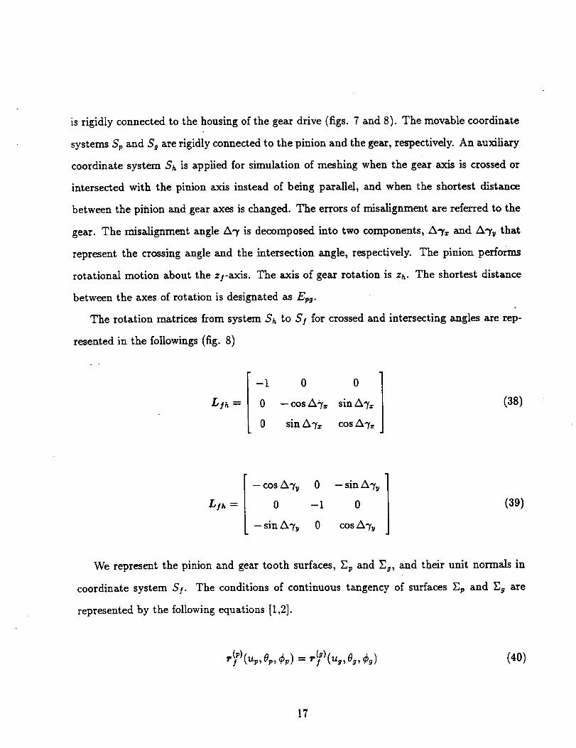
is rigidly connectedto the housing of the gear drive (figs. 7 and 8). The movable coordinate
systems S_ and S 9 are rigidly connected to the pinion and the gear, respectively. An auxiliary
coordinate system Sh is applied for simulation of meshing when the gear axis is crossed or
intersected with the pinion axis instead of being parallel, and when the shortest distance
between the pinion and gear axes is changed. The errors of misalignment are referred to the
gear. The misalignment angle A,y is decomposed into two components, /X,-f_ and/x% that
represent the crossing angle and the intersection angle, respectively. The pinion performs
rotational motion about the z f-axis. The axis of gear rotation is zh. The shortest distance
between the axes of rotation is designated as E_9.
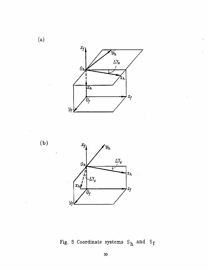
The rotation matrices from system Sh to S! for crossed and intersecting angles are rep-
resented in the followings (fig. 8)
Lib --
-1 0 0
0 --cosA-)'= sinA%
0 sin A% cos A%
(38)
Lib --
-cosA% 0 -sinA%
0 -1 0
--sinA% 0 cosA%
(39)
We represent the pinion and gear tooth surfaces, Ep and _, and their unit normals in
coordinate system SS. The conditions of continuous ta_gency of surfaces Ep and Eg are
represented by the following equations [1,2].
(40)
17

n_P)Cup, Op, ¢_) - n_g}(ug, 09, Cg/ (41)
Vector equation (41) provides only two independent equations since In P)l= = 1.
The total number of independent equations provided by (40) and (41) is five that relate six
parameters
f,(u,,,o,,,¢,,,u9,09,¢9)=o (i = 1,2,...5) (42)
The continuous solution of the system of nonlinear equations (42) is based on the following
pro_dure:
(1) Using an initial guess, we determine a set of parameters that satisfy equation system
(42). Thus
(43)
(2) One of the variable parameters, say ¢p, is chosen as the input one, and is supposed
.that the Jacobian
D(fl,f2, A,A,A)
D(ur,, 0_, ug, 0g, ¢9)(44)
differs from zero. The derivatives in the Jacobian are taken at point p(o).
(3) Then, equation system (42) can be solved in the neighborhood of p(0) by functions
18

(45)
(4) Vector function rp(up,8p)that determinesthe pinion surfaceZv and functions up(¢p),
0_(¢p) enable to determine the path of contact on Ep.
(5) Similarly, we can obtain the path of contact on the gear surface r.g using vector
function rg(ug,09) and functions ug(¢p), #9(¢9)-
(6) The paths of contact on pinion and gear tooth surfaces slightly deviate from helices
in the case of an aligned gear drive. The line of action for an aligned gear drive (the set of
contact points in SI) slightly deviates from a straight line that is parallel to the gear axes.
(7) The transmission function ¢g(¢p) deviates from the ideal transmission function, and
the function of transmission errors coincides with the predesigned parabolic function.
(8) The determination of dimensions and orientation of the instantaneous contact ellipse
needs the knowledge of the principal curvatures and directions of contacting surfaces and the
elastic approach of surfaces. This problem can be substantially simplified if the pinion-gear
principal curvatures and directions are expressed in terms of the principal curvatures and
directions of the generating surfaces and parameters of motion [1,2].
6. Numerical Example
The method developed in this report is illustrated with the example discussed below. The
design parameters of the pinion and gear are listed in Table 1. The numerical simulation
of meshing is performed for an aligned and misaligned gear drives with various errors of
alignment for the pinion and gear.
Case 1. Aligned gear drive
Figure 9 shows the transmission errors for the aligned gear drive. The TCA performed
19

Table 1: Designparametersof pinion and gear
tooth number
normal diametral pitch
normal pressure angle
helix angle on pitch cylinder
tooth length
modification coefficient
elastic approach
pinion gear
Np = 20 Y 9 = 1001 1
P,_=5..:--- P,_=5.--Zrt _n
a. = 20* ao = 20°
/_o = 30 ° /_o = 30 °
L=l.6 in. L=l.6 in.
a_ = 0.0008 a = 0.0014
= 0.007 ram. 6 = 0.007 ram.
confirms that the predesigned parabolic function of transmission errors exists. The maximum
transmission error is approximately 8 arc seconds. Figure 10 shows the contact pattern and
the contact path. The path of contact on the tooth surface is in the longitudinal direction.
The major axis of the instantaneous contact ellipse is 6 mm for the assumed elastic approach
of the surfaces equal to 0.007 mm.
Case 2. The pinion-gear rotation axes are crossed
Figures 11 and 12 show the transmission errors and the contact pattern for the case when
the crossing angle AT_o,, is 4 arc minutes. The maximum transmission error is 8 arc seconds
and contact paths are shifted up and down on the gear and pinion surfaces, respectively.
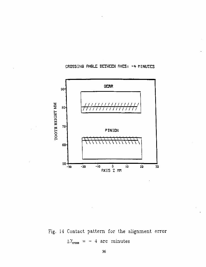
Figures 13 and 14 show the transmission errors and contact pattern for A%,oss - -4 arc
minutes.
Case 3. The pinion-gear rotation axes are intersected
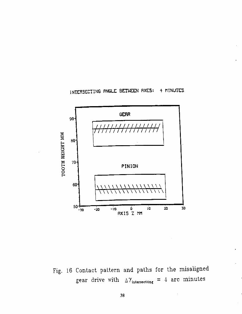
Figures 15 and 16 show the transmission errors for the misalignment AT_,t_,s_¢t = 4
arc minutes. Figures 17 and 18 show the transmission errors and contact pattern for the
mentioned above error of alignment.
2O
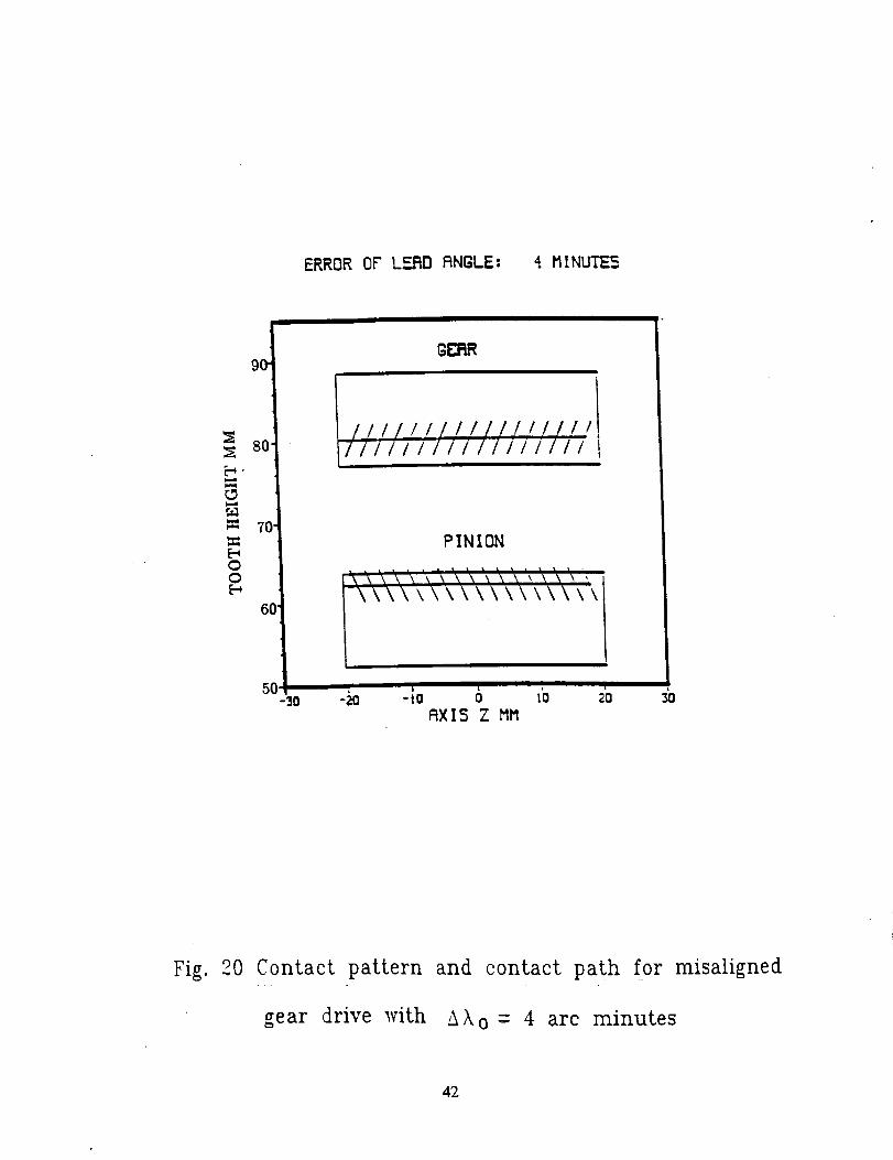
Case 4. Influence of error of lead angle
Figures 19 and 20 show the transmission errors and contact pattern when the error of
the lead angle is 4 arc minutes.
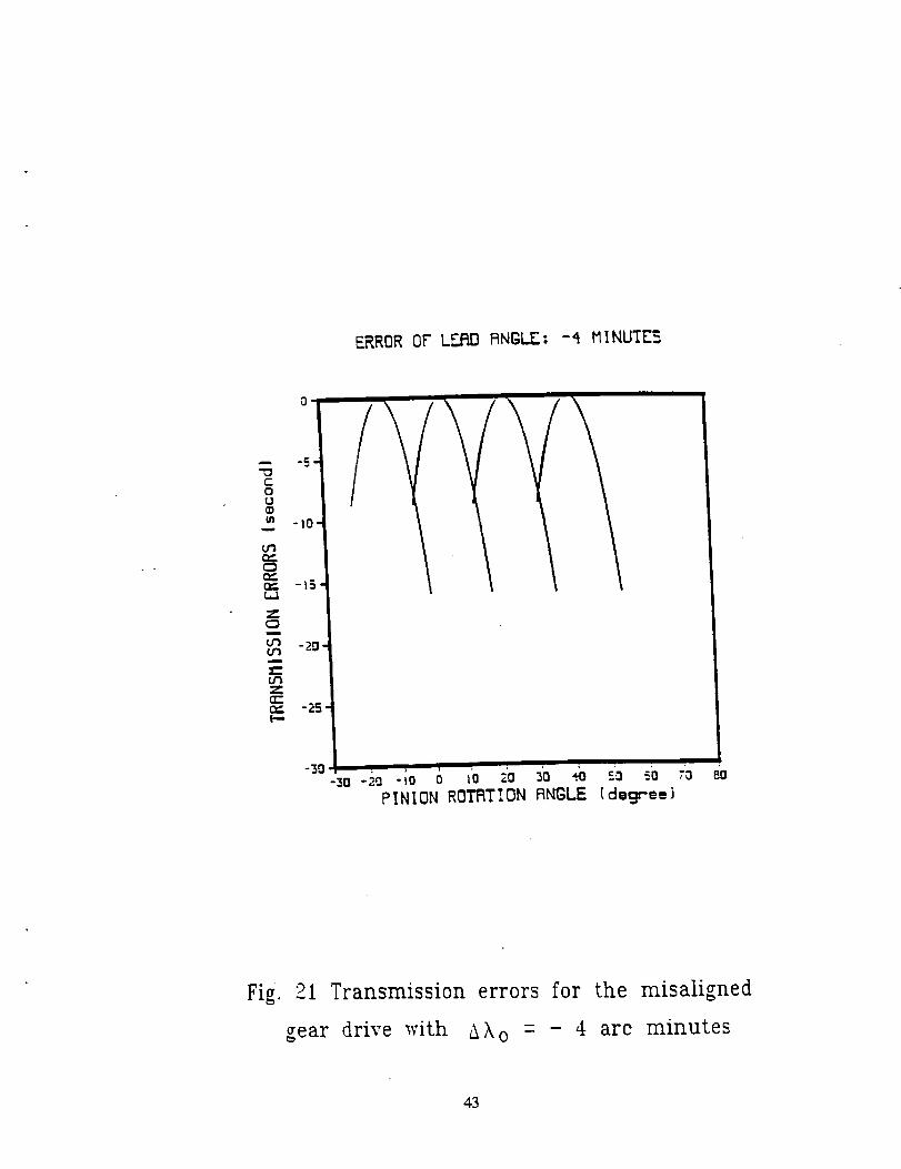
Figures 21 and 22 show the transmission errors and contact pattern when the error of
the lead angle is -4 arc minutes.
For all of above cases, the maximum transmission error does not exceed 8 arc second
(with very small deviations of this value).
7. Conclusion
From the analytical study presented in this report the following conclusions can be drawn:
(1) The interaction of a parabolic and a linear functions of transmission errors has been
• •discussed to prove the possibility to absorb almost, linear functions of transmission
errors caused by misalignment.
(2) Mismatched surfaces of two rack-cutters for generation of modified involute gears have
been proposed.
(3) Generation and geometry of pinion-gear modified tooth surfaces have been determined.
(4) Computerized simulation of meshing and contact of pinion-gear tooth surfaces has been
developed.
(5) An algorithm for determination of relations between the curvatures of the generating
and the generated surfaces has been developed.
(6) An algorithm for determination of the contact ellipse has been developed.
(7) Directions for users of application of developed computer programs for the design of
gears with the modified geometry and computerized simulation of their meshing and
contact have been developed (Appendix C).
21
References
1. Litvin, F.L.: "Theory of Gearing", NASA Publication 1212, 1989.
2. Litvin, F.L.: "Gear Geometry and Applied Theory", Prentice Hall, Englewood Cliffs,
New Jersey, 1994.
3. Litvin, F.L. and Krylov, N.N. and Erichov, M.L.: "Generation of Tooth Surfaces by
Two-Parameter Enveloping", Mechanism and Machine Theory, 1975, Vol.10, pp. 365-
373.
4. Litvin, F.L. and Zhang, J., Handschuh, R.F. and Coy, J.J.: "Topology of Modified
Helical Gears", Surface Topology, p.p. 41-58, March, 1989.
5. Reishauer CNC Gear Grinding Machines, Catalogs, Switzerland.
22

Cycle of meshing
(b)
J
Cycle of meshing
Fig. 1 Transmission function and transmission errors
for a misaligned gear drive
23

A
(_)
I
/o
/I
#
dr
I l
! #
#
(b)
Fig. 2 Interaction of parabolic and linear functions
24

(a)
(b)
'_lJ i-.I 1
Yii
(o)
Fig. 3 Normal sections of rack-cutters
25

Parallel to gear axes
Fig. 4 Orientation of rack-cutters with respect to gear axes
26

Xb
Oc, Y(_
N dp
Fig. 5 Normal section of pinion rack-cutter surface
27

(a)
Yn On,Og.,
y_ Eyt
x_ xg
X:
m
o_
(b)X e
I .o t
xp
0_,0_
Yp
Fig. 6 Generation of pinion and gear by rack-cutters
28

II
xy
zg
E.
Fig. 7 Coordinate system applied for tooth contact analysis (TCA)
29
(a)
(b)
IXh
t
I
' /)ipI _I
_h
Fig. 8 Coordinate systems Sh and Sf
30

(NO RS$EMBL_ ERRORS)
-- -5"O
C(3u4)(n -tO
r_
0¢ -15
¢=
-20m
:=U't_P"
(3:;0¢, -25"p.,
-_0 i io o _'o ia io ;0 io io 7h 80-30 -20 -
PINION ROT_'rlON RNGLE [degree}
Fig. 9 Transmission errors for the aligned gear drive
31

NO ASS_L_ _ORS
90"
8O
=
70"
=1
00
6O
5O
G_
I
-30 30
PINION
II\\\\\\\\\\\\\\\\\
I\\\\\\\\\\\\\\\\\
-_ -;o 6 l'o 2'oAXIS Z MM
Fig. 10 Contact paths and pattern for the aligned gear drive
32

CROSS ING RNGLE BL"F_E[N RXF_.5: _ M !NUTE$
=_
ou
-IQ'
tm
C_
o_ -iS
tm -20ttlmi
om
n., -2S
-zo-_o-io o _o 20 ,._:B _o 6oPINION RO_I_TION ANBLE [degree)
7'o eo
Fig. 11 Transmission errors for the alignment error
&?'cross-4 arc minutes
33

CROSSING RNGLE BL-_EEN RXF_.5: 4 MINUTL"5
PINION
Fig. 12 Contact pattern for the alignment error
_'cross= 4 arc minutes
34

CRD$5|NG _NGLE BL-'IIJEE3qAXES: -4 MINUTES
-3°-3o-_o-:o o 1'o 20 _.b ,;o S._ _'oPINION RO'II_TION ANGLE _degreeJ
Fig. 13 Transmission errors for the alignment error
17oro_s= - 4 are minutes
35
CROSSING RNGLE BE'_E'_ RXE_: -+ MINUT_
00
90'
80
60
50-_o -zo
_ERR
II/IIII III/IIIIIII IIII
PINION
-io o =i_F_XI5Z MM
2'0 3O
Fig. 14 Contact pattern
_7cros' = - 4 arc
for the alignment
minutes
error
36

INTERSECTING RNGLE EE"i'NEF..N _XE$: 4 MINUTE5
o-- -5- /
ou
m -tO
C3n,,
U'J -20
EZ
1..,,,
/
-3O-3o-_o-io 6 _'o 2o _.'o ;o s'o 6o ;b
PINION ROTRTIDN RNGLE {degree}
BO
Fig. l fi Transmission errors for misaligned gear drive _vith
'_'_/intersecttin{ -- 4 arc minutes
37
INTERSECTINGANGLEBET6_ AXES: _ MINUTE5
m=
F.00
gO'
80
70
6O
50
GE_:_e
PINION
-m -_o -io 6AXIS Z MM
\\\\\\\\
I
1'o m m
Fig. 16 Contact pattern and paths for the misaligned
gear drive _vith &Ti=te,s,cttin_= -_ arc minutes
38

INTERSECTING RNgLE BL'TNE_ RXES: -_ MINUTES
-5"0Cou
m -iO,
C3r_"
-IS
(:3
r_ -20
t_.mD -
_--.u'J
CZ:O_ -25
-30-zo-_-io o io 2b _o _.b so 60
PINION ROTFITION RNBL_ [degree)
7b Bo
Fig. 17 Transmission errors for the misaligned
gear drive with AYintersectting = - 4 arc minutes
39

INTL"RSECTING RNGL_ BL-_ RXES: -4 MINUTIa
E-,w_
E-.OO
9O
8O
7C
6O
GI_=LR
PINION
"30SXl$ Z MM
Fig. 18 Contact pattern for the misaligned
gear drive with -_)'iatersecttiag =- 4 arc minutes
4O

ERROR OF LF_RO RNGLI_: _ MINUTES
"3°-_o-_ -io o _o _ _ _ s_ 60 7'oPINION ROTRTION ANGL_ [degree)
Fig. 19 Transmission errors for the misaligned
gear drive _vith AXo = 4 arc minutes
41
ERROR OF LF.BD RNGLE: 4 MINUTE _.
9O
8O
70
00
6O
PINION
/
//
Fig. 20 Contact pattern and contact path for misaligned
gear drive with _ko = 4 arc minutes
42
ERROR 0F LF..I_D RNGLE: -4 MINUTE_
PINION ROTPiTION ANGLE (degree)
Fig. 21 Transmission errors for the misaligned
gear drive _vith AXo - - 4 arc minutes
43

ERROR OF PRESSURE P,,NGL.F.: -4 M INUT]_5
9O
8O
r.,.,l
70
00
6C
G_
PINION
I
RX|S Z MM
Fig. 22 Contact pattern and contact paths for the misaligned
gear drive with __ko = - 4 are minutes
44

Appendix A. Relations between the Curvatures of the Generating and Generated
Surfaces
Direct Relations between Principal Curvatures and Directions of Mating Sur-
faces
The main advantage of this approach (proposed by Litvin) is the possibility to determine
the principal curvatures and directions of the generated surface in terms of principal curva-
tures and directions of the generating tool surface, and the parameters of motion. In this
case, the tool surfaces for the generation of the gear and the pinion tooth surfaces are rack
cutters. The equations developed permit a simplified computational procedure.
The system of equations that relate the principal curvatures and directions of the gen-
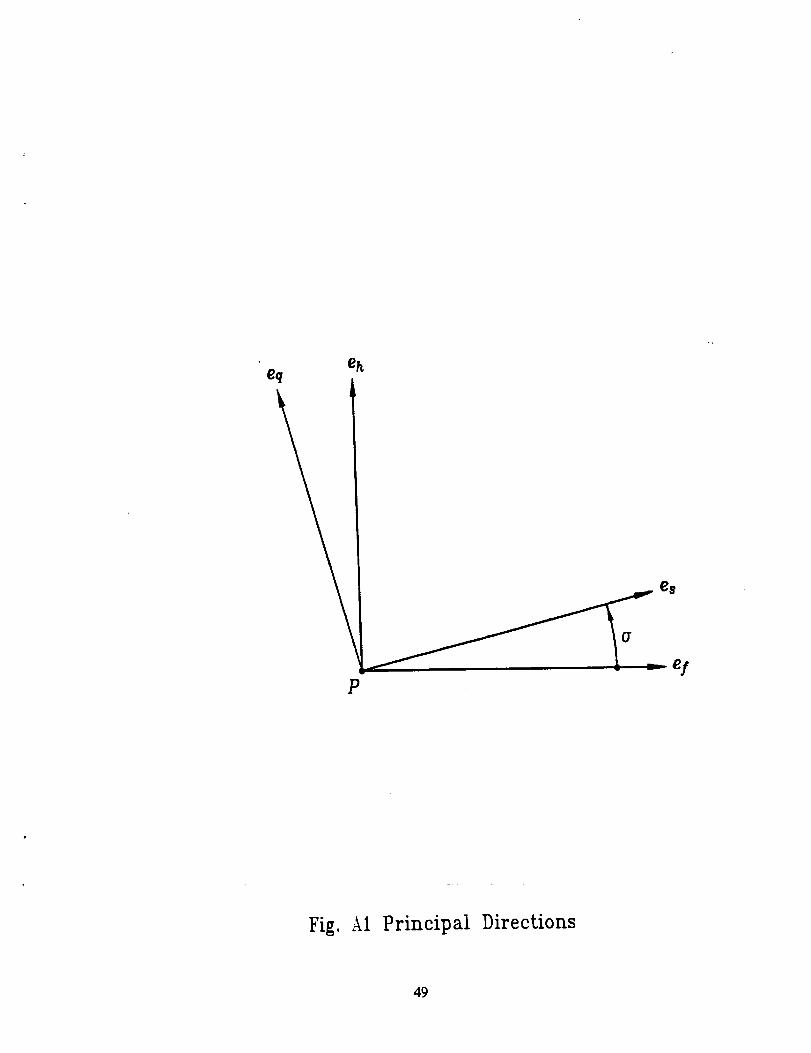
erating and generated surfaces is as follows. Consider that unit vectors e/and eh represent
the principal directions on the tool surface Z1 at point P of tangency of surfaces Z1 and _
(fig. A1). The principal curvatures on the mating surfaces x! and xh of the tool are given;
the parameters of motion (see below) are also given.
The goal is to determine angle cr that is formed by unit vectors ef and e,, and principal
curvatures t_, and tzq. (The unit vectors es and eq represent the principal directions on
surface _2). The system of equations for determination of a, tc,, and t% is as follows.
tan 2_ = 2blsb25 (AI)
2b,sb25 = b_s - b_s - (x! - xh)ta3 (A2)xq - _, = ta3 sin 2a ta3 cos 2o-
xq + x, = xy + x^ +b_s + b_s
t33
(A3)
Here:
45

(A6)
+(nx _('_))•vO__ _(_(,_._,)__ _(_(_).eh)_
The nomenclature for equations (A4) to (A6) is described as follows:
wO) angular velocity of the generating tool
w(2). angular velocity of the generated gear
w (z_) defined as w (1) - _(2)
vl_ ) transfer motion velocity of the generating tool
v_2) transfer motion velocity of the generated gear
v(l lde nedas
n surface unit normal vector
The equations discussed above are used in the TCA program for determination of the
contact ellipse at the points of contact path of the modified helical gear drive.
Numerical Example
The input and output for the determination of the principal curvatures of the pinion
tooth surface are shown in Tables A1 and A2. The input and output for the determination
of the principal curvatures of the gear tooth surface are shown in Tables A3 and A4.
46

Table A1 Input Data
Description
firstprincipalcurvature of tool
second principalcurvature of tool
firstprincipaldirectionof tool
second principaldirectionof tool
angular velocityof tool (I/sec)
angul_ velocityof pinion (i/sec)
transfervelocityof tool
(mm/sec)
transfervelocityof pinion
(mm/- ec)
surfacenormal of tangent point
Symbol Values.=
_.t" -0.0016 (l/ram)
_h 0.0 (l/ram)
e! [0.0016 -- 0.4999 0.8660] r
eh
_0) [0.0 0.0 0.0] r
[0.9387 0.2992 0.1710] T
Vt(2)
[0.0 0.0 1.0] r
[0.0 58.6588 0.0] r
[--0.1514 58.5951 0.0] T
n [-0.3420 0.8138 0.4698] T
Table A2 Output Data
Description (for pinion) Symbol Values
first principal curvature
second principal curvature
first principal direction
s, -0.001543 (l/mm)
_q 0.03907 (1/mm)
e, [0.1751 -- 0.4361 0.8827] T
second principal direction eq [0.9222 0.3865 0.0080] T
47
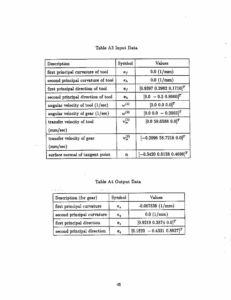
Table A3 Input Data
Description Symbol Values
first principal curvature of tool s/ 0.0 (1/mm)
second principal curvature of tool sh 0.0 (l/ram)
first principal direction of tool e/ [0.9397 0.2962 0.1710] 7
second principal direction of tool eh [0.0 - 0.5 0.8660] 7
angular velocity of tool (1/sec) w (1) [0.0 0.0 0.0] T
angular velocity of gear (1/sec) w (2) [0.0 0.0 - 0.2003] T
transfer velocity of tool v_ ) [0.0 58.6588 0.0] T
( /sec)
transfer velocity of gear v_ ) [-0.2096 58.7218 0.0] T
(mm/sec)
surface normal of tangent point n [-0.3420 0.8138 0.4698] 7
Table A4 Output Data
Description (for gear) Symbol Values
first principal curvature _, -0.007836 (1/mm)
second principal curvature tcq 0.0 (1/mm)
first principal direction e, [0.9219 0.3874 0.0] r
second principal direction e_ [0.1820 - 0.4331 0.8827] T
48
eheq
P
Fig.A1 Principal Directions
49

Appendix B. Contact Ellipse
Determination of Dimensions and Orientation of Instantaneous Contact Ellipse
The gear tooth surfaces are in point contact at every instant. Due to elastic deformation
of gear tooth surfaces the contact is spread over an elliptical area and the center of the ellipse
coincides with the instantaneous contact point. The bearing contact is formed as the set of
instantaneous contact ellipses.
The dimensions and orientation of the instantaneous contact ellipse can be determined
using the data about the principal curvatures and directions of the contacting surfaces, and
the elastic approach of the surfaces. The elastic approach depends on the applied load but
we will consider it as a given value that is known from experimental data.
The determination of the instantaneous contact ellipse is based on the following equations
(proposed by Litvin):
cos 2a (1) - gl - g2 cos 2or(g_ - 29192 cos2a -t- g_)1/2
(B1)
sin 2a (1) -- g2 sin 2a- 2g,g cos +
(B2)
I' l'" I'l2a--2 _ , 2b-2 _ (B3)
where
1 r_(_) _(_)A = _t r. - - (g_ - 2gig2 cos 2or + g_)112]
(B4)
1 r_(_) _(_)B = _L r - + (g_ -- 2glg2 cos 2a+gg)'/2]
(B5)
,cg)= _(0+ _xz,
50

Here (fig. B1) o (1) is the angle that is formed by axis 77of the contact ellipse with the unit
vector e_1) of the principal direction on surface _1; cr is the angle formed by unit vectors
e_1) and e(/2) of the principal directions of the contacting surfaces; 2a and 2b are the axes of
the contact ellipse; 6 is the elastic approach; and _(ri) and ..(0_u are two principal directions of
tooth surface i.
Numerical Example
The input and output for the determination of the contact ellipseare shown in Tables
B1 and B2.
Table B1 Input Data
Description Symbol Values
pinion firstprindpal curvature s8 -0.001543 (I/ram)
pinion second principalcurvature _q 0.03907 (I/nun)
pinion firstprincipaldirection e8 [0.1751 - 0.4361 0.8827]T
pinion second principaldirection e_ [0.9222 0.3865 0.0080]r
gear first principal curvature _1 - 0.007836 (1/ram)
0.0 (l/ram)gear second principal curvature
gear first principal direction
gear second principal direction
elastic approach
e s [-0.9219 - 0.3874 0.0] r
eh [-0.1820 0.4331 0.8827] T
6 0.007
Table B2 Output Data
Description Symbol Values
long axisof contact ellipse 2a 6.026 (ram)
short axis of contact ellipse 25 1.092 (ram)
angle between long axis and a (I) 89.87 (deg)
the firstprincipaldirectionof pinion
51

O"
Fig. B1 Orientation and dimensions of contact ellipse
52

Appendix C. Directions for Users of Application of Computer Program
C.1 Introduction
The name of the computer program is HELTCA.FOR. It is written in FORTRAN77
language. The operating system is CMS-9.0. A subroutine DNEQNF to solve a system of
nonlinear equations should be available in the Math-Library or working environment. The
subroutine is not included in the program. The program will call the subroutine DNEQNF
several times.
C.2 Input Block
The input block consists of three parts: (1) design parameters of pinion and gear; (2) the
controlled modification parameters; and (3) parameters for TCA.
Part i. Design parameters of plnion and gear
In the beginning of the computer program, you can read the following lines:
C... All ..... COEFFICIENT FOR TRANSFORMATION OF DEGREE TO RADIAN
A1 I=DACOS(-1.D0)/180.D0CC... KHD=I FOR RIGHT-HAND PINION AND LEFT-HAND GEARC... KHD=2 FOR LEFT-HAND PINION AND RIGHT-HAND GEAR
KHD=2
If you write "KHD=I', the computer will use the necessary equations for the case of
right-hand pinion and left-hand gear. The computations will be accomplished for a left-
hand pinion and right-hand gear if you use "KHD=2".
Then, the variable definition for the pinion follows:
CC... INPUT THE DESIGN PARAMETERS OF PINION
Coto
C... TN1 ............ GEAR NUMBER OF TEETHC... PN1 ............ NORMAL DIAMETRAL PITCH (1/MM)
C... PSIN1 ......... NORMAL PRESSURE ANGLE (RAD.)C... BETAP1 ..... HELICAL ANGLE ON PITCH CYLINDER (RAD.)
C... ADG1 ......... ADDENDUM (MM)
53

C...DEGI ..........DEDENDUM (MM)
C...LAMDPI .....LEAD ANGLE ON PITCH CYLINDER (RAD.)
C... FWl ............FACE WIDTH (MM)
C... RPTI ..........RADIUS OF PITCH CYLINDER (MM)
C... RBTI ..........RADIUS OF BASE CYLINDER (MM)
C... RAT1 ..........RADIUS OF ADDENDUM CYLINDER (MM)
C... RDTI ..........RADIUS OF DEDENDUM CYLINDER (MM)
C...PSITI .........TRANSVERSE PRESSURE ANGLE (RAD.)
C... LAMDBI ....LEAD ANGLE ON BASE CYLINDER (RAD.)
C
In accordance with our numerical example (see Table I), the following data would 'be
used:
TNI=20.D0
PNl=5.D0/25.4D0PSINI=All*20.D0LAMDPI=All*60.D0BETAPI=All*30.D0FWl=25.4D0*l.6D0
ADGI=I.D0/PN1
DEGl=l.25D0/PN1
The following variables are used for the gear:
CC,oo
CCe°°
C°.o
C.°o
C°.,
Co,°
C.°°
C..o
C:..
Co°°
Coo°
C°°°
C°.°
C°°°
C°°o
C
INPUT THE DESIGN PARAMETERS OF GEAR
TN2 ..............GEAR NUMBER OF TEETH
PN2 ..............NORMAL DIAMETRAL PITCH (I/MM)
PSIN2 ..........NORMAL PRESSURE ANGLE (RAD.)
BETAP2 .....HELICAL ANGLE ON PITCH CYLINDER (RAD.)
ADG2 ........... ADDENDUM (MM)
DEG2 ........... DEDENDUM (MM)LAMDP2 ..... LEAD ANGLE ON PITCH CYLINDER (RAD.)
FW2 .............. FACE WIDTH (MM)RPT2 ...........RADIUS OF PITCH CYLINDER (MM)
RBT2 ...........RADIUS OF BASE CYLINDER (MM)
RAT2 ...........RADIUS OF ADDENDUM CYLINDER (MM)
RDT2 ...........RADIUS OF DEDENDUM CYLINDER (MM)
PSIT2 ..........TRANSVERSE PRESSURE ANGLE (RAD.)
LAMDB2 .....LEAD ANGLE ON BASE CYLINDER (RAD.)
From the design parameters listed in Table 1, we have
54
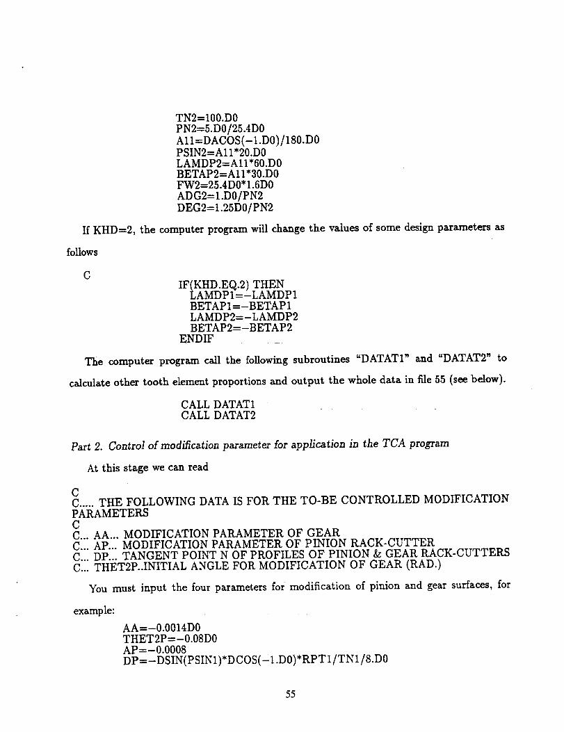
TN2=I00.D0PN2=5.D0/25.4D0AII=DACOS(-I.D0)/180.D0PSIN2=AII*20.D0LAMDP2=AII*60.D0BETAP2=A11*30.D0FW2=25.4D0*I.6D0ADG2=I.D0/PN2DEG2=I.25D0/PN2
If KHD=2, the computer program will change the values of some design parameters as
follows
C
IF(KHD.EQ.2) THENLAMDPI=-LAMDP1BETAPI=-BETAP1LAMDP2=-LAMDP2BETAP2=-BETAP2
ENDIF
The computer program call the following subroutines "DATATI" and "DATAT2" to
calculate other tooth element proportions and output the whole data in file 55 (see below).
CALL DATATICALL DATAT2
Part 2. Control of modification parameter for application in the TCA program
At this stage we can read
CC ..... THE FOLLOWING DATA IS FOR THE TO-BE CONTROLLED MODIFICATIONPARAMETERSCC... AA... MODIFICATION PARAMETER OF GEARC... AP... MODIFICATION PARAMETER OF PINION RACK-CUTTERC... DP... TANGENT POINT N OF PROFILES OF PINION & GEAR RACK-CUTTERS
C... THET2P..INITIAL ANGLE FOR MODIFICATION OF GEAR (RAD.)
You must input the four parameters for modification of pinion and gear surfaces, for
example:
AA=-0.0014D0THET2P=-0.08D0AP--0.0008
DP=-DSIN(PSIN1)*DCOS(-1.D0)*RPT1/TNI/8.D0
55
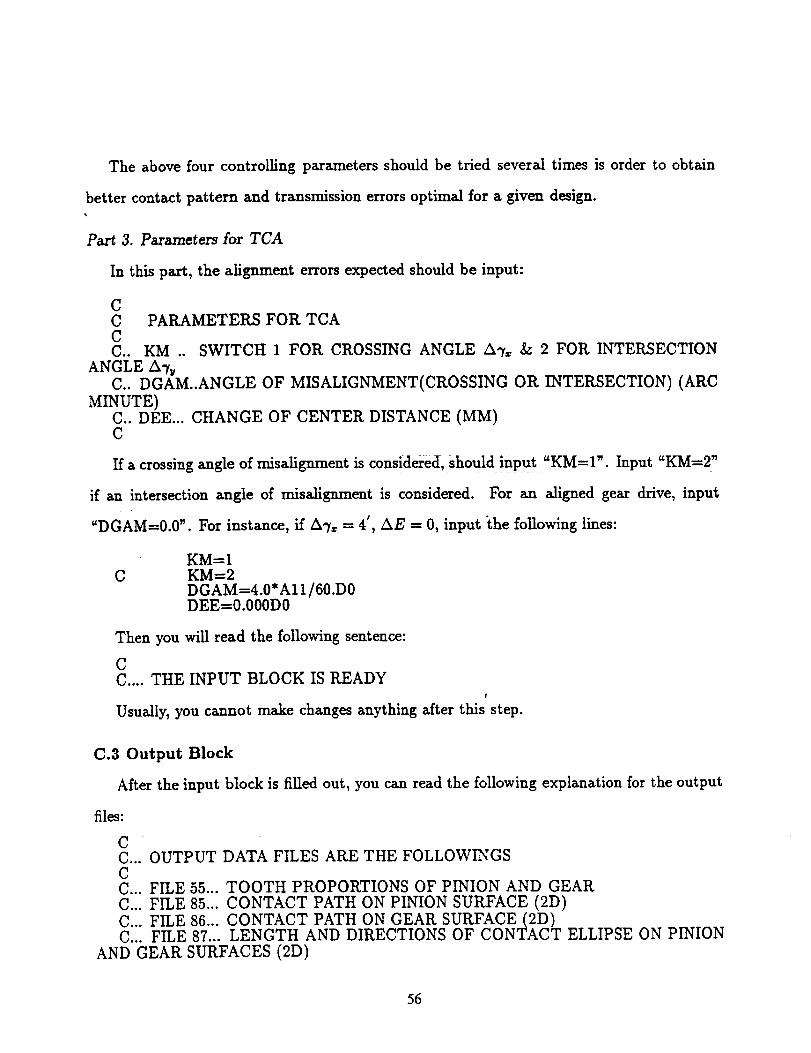
The abovefour controlling parameters should be tried several times is order to obtain
better contact pattern and transmission errors optimal for a given design.
Part 3. Parameters for TCA
In this part, the alignment errors expected should be input:
CC PARAMETERS FOR TCA
CC.. KM .. SWITCH 1 FOR CROSSING ANGLE AT= & 2 FOR INTERSECTION
ANGLE A%C.. DGAM..ANGLE OF MISALIGNMENT(CROSSING OR INTERSECTION) (ARC
MINUTE)
C.. DEE... CHANGE OF CENTER DISTANCE (MM)C
If a crossing angle of misalignment is considered, Should input "KM=I'. Input "KM=2"
if an intersection angle of misalignment is considered. For an aligned gear drive, input
"DGAM=0.0". For instance, if AT= = 4', AE = 0, input the following lines:
CKM-1KM-2
DGAM-4.0*A11/60.D 0DEE=0.000D0
Then you will read the following sentence:
CC .... THE INPUT BLOCK IS READY
!
Usually, you cannot make changes anything after this step.
C.3 Output Block
After the input block is fired out, you can read the following explanation for the output
files:
C =
C... OUTPUT DATA FILES ARE THE FOLLOWINGSCC... FILE 55... TOOTH PROPORTIONS OF PINION AND GEARC... FILE 85... CONTACT PATH ON PINION SURFACE (2D)
C... FILE 86... CONTACT PATH ON GEAR SURFACE(2D)C... FILE 87... LENGTH AND DIRECTIONS OF CONTACT ELLIPSE ON PINION
AND GEAR SURFACES (2D)
56

C... FILE 90... TRANSMISSION ERRORSCC..o,.lJ..o..H,g.lel
C
1) File 55
In File 55 the information about the pinion and gear are listed.
2) Files 85 and 86
3:2 . 2_0.5There are two coordinates in File 85 for each contact point of the pinion: Radial ( v+_pj
and axial zp. There are two coordinates in File 86 for each contact point of the gear: Radial
(x 2 -I- y_)0.s and axial zg,g g
3) File 87
There are 5 values in File 87 for each pair of contact points of the pinion and gear. The
first one is the value of the major semi-axis of the contact ellipse. The second and third
values are the cosine directions of the major axis of the contact ellipse on the pinion tooth
surface. The last two values are the cosine direction of the major axis of the contact ellipse
on the gear tooth surface.
C.4 Computer Program
57

C ..... HELICAL GEARS ..................
Co _ u
Co I e
Co . .
Co • •
.......... TCA FOR MODIFIEDPROGRAM HELTCA
IMPLICIT
REAL*8
REAL*8
REAL*8
REAL*8
REAL*8
REAL*8
REAL* 8
REAL*8
REAL*8
REAL*8
REAL*8
REAL*8
REAL*8
REAL*8
REAL*8
REAL* 8
REAL*8
REAL*8
COMMON
COMMON
COMMON
REAL*8 (A-H, O-Z)
xi (9),x(9) ,F(9)LFI (3,3) ,LH2 (3,3) ,LIF(3,3), L2H(3,3)
RIF(3) ,R2F(3) ,NIF (3) ,N2F(3)
DPHI (2,180), DDPHI (2,180,4)
ELAL(180) ,ELI(2,180), EL2 (2,180)
LFH(3,3) ,LHF(3,3)V1(3) ,V2 (3) ,V3 (3) ,V4 (3) ,VS (3)RG2 (3) ,NG2 (3)
RGI (3) ,NGI (3)
ui(3) ,uJ (3),UK(3)LAMDP2, LAMDB2
LAMDP1, LAMDBI
UT2, KT21, KT22
AVCl (3) ,VTRI (3) ,AVC2 (3) ,VTR2 (3)KSIGI, KSIG2, KFF, KHH
EFN (3), EHN (3), WIVT2 (3) ,WVI2 (3) ,W2VTI (3), KF,KH,KS,KQKM2, KT2KFP, KHP, KFG, KHG
/A300/ ES(3),EQ(3)/A310/ KFF, KHH
/A340/ EFF(3),EHH(3)
COMMON /A360/ A,B,SI(3),FI(3)COMMON/A200/ Wl(3),W2(3),W12(3),VTl(3),VT2(3),V12(3)COMMON /A2101 EX(3),EF(3),EH(3)
COMMON /A212/ EF2(3) ,EH2 (3) ,KF2,KH2 : _ _ : _COMMON /A220/ KF,KH
COMMON /A230/ ET(3),EM(3)
COMMON /A380/ KS,KQ
COMMON /A4001 VTll(3) ,VT12(3) ,VT21(3) ,VT22(3)COMMON /A401/ KHP,KFP,KHG,KFGEXTERNAL FCNG, FCNC, FCNT
COMMON /AXIS/ UI,UJ,UKCOMMON /NET/ RR,DD
COMMON /DD/ DF,KPRI
COMMON /DATT2 / TN2, PN2 ,PSIN2, BETAP2, ADG2, DEG2, LAMDP2,
& UP2 ,FW2, RPT2, RBT2, RAT2, RDT2, PSIT2, LAMDB2
COMMON /DATT/ TNI, PNI, PSINI, BETAPI, ADGI, DEGI, AMDPI,
& FWI, RPTI, RBTI, RAT1, RDTI, PSITI, LAMDBI
COMMON /B2/XNPI, YNPI, ZNPI, XNP2, YNP2, ZNP2
COMMON "/B4/XI, Y1, Z1, XNI, YNI, ZNI
COMMON /BS/X2, Y2, Z2, XN2, YN2, ZN2
COMMON /B6/THET2P, DGPHI2
COMMON /Wl/ ETAWI, UPPI, SPPI, ETAW2, UPP2, SPP2COMMON /SG1/ RG1,NG1,AP,DP
COMMON /SG2/ RG2,NG2,AA
COMMON /ATT/ PHI1, PHI2, RIF, R2F, NIF, N2F, LFH, CO, DGAM, DPHI2COMMON /MVT/ LFI, LH2
COMMON /AST/ ICONT
COMMON /ATS/ DPHI1All ..... COEFFICIENT FOR TRANSFORMATION OF DEGREE TO RADIAN
AII=DACOS (-1 •D0) /180. DOKHD=I FOR RIGHT-HAND PINION AND LEFT-HAND GEAR
KHD=2 FOR LEFT-HAND PINION AND RIGHT-HAND GEAR
KHD=2
INPUT THE DESIGN PARAMETERS OF PINION
TNi ........ GEAR NUMBER OF TEETH
PN1 ........ NORMAL DIAMETRAL PITCH (MM)
58

C... PSINI ...... NORMAL PRESSURE ANGLE (BAD.)
C... BETAPI ..... LEADING ANGLE OF THE HELIX ON PITCH CYLINDER (BAD.)
C... ADGI ....... ADDENDUM (MM)
C... DEGI ....... DEDENDUM (MM)
C... LAMDPI .... HELIX ANGLE ON PITCH CYLINDER (BAD.)
C... FWI ........ FACE WIDTH (MM)
C... RPTI ....... RADIUS OF PITCH CYLINDER (MM)
C... RBTI ....... RADIUS OF BASE CYLINDER (MM)
C... RAT1 ....... RADIUS OF ADDENDUM CYLINDER (MM)
C... RDTI ....... RADIUS OF DEDENDUM CYLINDER (MM)
C... PSITI ...... TRANSVERSE PRESSURE ANGLE (RAD.)
C... LAMDBI .... HELIX ANGLE ON BASE CYLINDER (BAD.)
TNI=20. DO
PNI=5. D0/25.4D0PSINI=AI I* 20. DO
LAMDP 1=All* 60. DO
BETAPI_AII*30. DO
FWI=25.4D0*I. 6D0 .....
ADGI=I. D0/PNI
DEGI=I. 25D0/PNIC... INPUT THE DESIGN PARAMETERS OF GEAR
C... TN2 ........ GEAR NUMBER OF TEETH
C... PN2 ......... NORMAL DIAMETRAL PITCH (I/MM)
C... PSIN2 ....... NORMAL PRESSURE ANGLE (RAD.)
C... BETAP2 ...... LEADING ANGLE OF THE HELIX ON PITCH CYLINDER (RAD.)
C... ADG2 ........ ADDENDUM (MM)
C... DEG2 ........ DEDENDUM (MM)
C... LAMDP2 ..... HELIX ANGLE ON PITCH CYLINDER (BAD.)
C... FW2. ........ FACE WIDTH (MM)
C... RPT2 ........ RADIUS OF PITCH CYLINDER (MM)
C... RBT2 ........ RADIUS OF BASE CYLIND_ (MM)
C... RAT2 ........ RADIUS OF ADDENDUM CYLINDER (MM)
C... RDT2 ........ RADIUS OF DEDENDUM CYLINDER (MM)
C... PSIT2 ....... TRANSVERSE PRESSURE ANGLE (BAD.)
C... LAMDB2 ..... HELIX ANGLE ON BASE CYLINDER (BAD.)
TN2=I00. DO
PN2=5. DO /25.4D0AII=DACOS (-I.D0)/180.D0
PSIN2=AII* 20. DO
LAMDP2 =All* 60. DO
BETAP2=AII* 30. DO
FW2=25.4D0*I. 6D0
ADG2= 1. D0/PN2
DEG2=I. 25D0fPN2
IF (KHD. EQ. 2) THENLAMDPI=-LAMDP 1
BETAPI=-BETAP 1
LAMDP2=-LAMDP2
BETAP2=-BETAP2
ENDIF
CALL DATATI
CALL DATAT2
C... THE FOLLOWING IS FOR CONTROLLINGPARAMETERS
C... AA... MODIFICATION PARAMETER OF GEAR
C... AP... MODIFICATION PARAMETER OF PINION RACK-CUTTER
C.. DP .... TANGENT POINT N OF PROFILES OF PINION & GEAR RACK-CUTTERS
C.. THET2P. .INITIAL ANGLE FOR MODIFICATION OF GEAR (BAD.)
C
C PARAMETERS FOR TCA
C
59

C.. KM .. SWITCH 1 FOR CROSSING & 2 FOR INTERSECTING MISALIGNMENT
C.. DGAM..ANGLE OF DISALIGNMENT(CSOSSING OR INTERSECTING) (ARC MINUTE}
C.. DEE... CHANGE OF CENTER DISTANCE (MM)KM=I
C KM=2
DGAM=O. DO
DEE=O. O00D0
AA=-0. 0014D0
THET2P---- 0.08D0
AP=-0. 0008
DP=-DSIN (PSINI) *DCOS (-i. DO) *RPTI/TNI/8. DOC... THE INPUT BLOCK IS OVER HERE
C
C... OUPTPUT DATA FILES ARE THE FOLLOWINGS
C
C... FILE 55... TOOTH PROPORTIONS OF PINION AND GEAR
C... FILE 85... CONTACT PATH ON PINION SURFACE (2D)
C... FILE 86... CONTACT PATH ON GEAR SURFACE (2D)
C... FILE 87... DIRECTIONS OF LONG AXIS OF CONTACT ELLIPS (2D)C... FILE 90 ...TRANSMISSION ERRORS
DO 901 I=I,3
UI (I) =0 .DO
uJ(I) =0,D0UK(I) =0.D0
901 CONTINUE
UI(Z)=I.D0UJ(2)=I.D0UK(3)=I.D0
C .. EE2. .... GEAR RATIO
EE2=TNI/TN2C .. CC ...... CENTER DISTANCE OF GEAR DRIVE
CC=RPTI+RPT2+DEE
C .. CALCULATE CONTACT POINT ON MEAN SECTION WITHOUT MISALIGNMENT
ICONT-=-1
N=6
ERRREL=0. ID-6
ITMAX=I000
C
C
C
C
CALL MIAL (KM, 0. D0, LFH)
XI (1)=0.D0
XI (2.)=0. DO
XI(3)=0.D0
XI(4)=0.D0
XI (5) =-0. DO
XI (6) =0. D0DD=0. DO
CALL DNEQNF(FCNG,ERRREL, N,ITMAX,XI,X,FNORM)
PHISS 1=X (6)PHI IMEA=X (6 )
C .. CALCULATE CONTACT POINT ON EDGE SECTION WITHOUT MISALIGNMENT
DD=-0.5D0*FWI _
ERRREL=0.1D-8
c
C
PHISS2=X (6)
C .. CALCULATE CONTACT POINT ON EDGE SECTION
CALL DNEQNF(FCNG,ERRREL,N,ITMAX,XI,X,FNORM)
WITH MISALIGNMENT
6O

C
C
C
C
1330
C • •
C
Coo•
Coo•
Coo•
Cmig
Coeo
N=6
ERRREL=0.1D-6
ITMAX=I000
CALL MIAL (KM, DGAM, LFH)
xxc1)=xc1)x1(2)=x(2)xic_)=x(3)xi(4)=x(4)xI CS)=x(s)xI Ce)=x(e)
CALL DNEQNF(FCNG,ERRREL,N,ITMAX,XI,X,FNORM)
CONTINUE
PHIl=X(6)
PHIISTA=X(6)THE FOLLOWING IS FOR TCA
ICONT=2N=5
ERRREL=0.1D-5
ITMAX=400
STP=(PHISS2-PHISSI)/36.D0NN=72
DO I010 I=I,NN
PHII=PHIISTA-(I-I)*STP
xI(1)=x(1)XI(2)=X(2)
xi(3)=x(3)XI(4)=X(4)
xI(s)=x(s)
CALL DNEQNF(FCNG,ERRREL, N,ITMAX,XI,X,FNORM)
IF (RGI (3) .GT. (0.5D0*FWI))ROTATING VELOCITY OF CUTTER
Wl (i) =0. DO
Wl (2)=o. DOW1 (3) =0. DO
ROTATING VELOCITY OF PINION
W2 (1)=0.D0
W2 (2)=0.D0
W2 (3)=1.D0NORMAL OF CUUTER IN CUTTER SYSTEM
EX(1)=XNP1Ex(2)=Y_mlEX(3)=ZNP1
TRANSFER VELOCITIES OF CUTTER AND
CALL EQVEC (VT1, VTll)
CALL EQVEC (VT2 ,VTI2)
RELATIVE VELOCITIS OF CUTTER WRT.
CALL ADDVEC (WI2 ,W1,W2, -1.D0)
CALL ADDVEC (V12 ,VTI,VT2, -I.D0)
KF=KFP
KH=KHP
GO TO 1011
IN CUTTER SYSTEM
INCUTTER SYSTEM
PINION IN CUTTER
PINION IN CUTTER
PRINCIPAL CURVATUTES AND DIRECTIONS OF PINION
CALL CURVT(1)PRINCIPAL DIRECTIONS OF PINION IN PINION SYSTEM
CALL EQVEC(EFF,ES)
61
SYSTEM
SYSTEM

Calo
Ciio
Cooa
CDeo
CIII
CoIo
Coll
Coo.
CALL EQVEC (EHH, EQ)ROTATING VELOCITY OF
WI(1)=0.D0
W1 (2) =0. DO
WI(3)=O.D0ROTATING VELOCITY OF
W2 (I) =0. DO
w2 (2) =0. DOW2 (3 )=-DGPHI2
NORMAL OF CUUTER IN
EX (I) =XNP 2
EX (2) =¥NP2
EX (3) =ZNP2TRANSFER VELOCITIES
CALL EQVEC (VTI, VT21)
CALL EQVEC(VT2 ,VT22)
CALL EQVEC (EF, EF2)
CALL EQVEC (EH, EH2 )KF=KF2
KH=KH2
CUTTER IN CUTTER SYSTEM
GEAR IN CUTTER SYSTEM
CUTTER SYSTEM
OF CUTTER AND PINION
RELATIVE VELOCITIS OF CUTTER WRT. GEAR
CALL ADDVEC (W12, W1, W2, -1. D0)
CALL ADDVEC (VI2 ,VTI, VT2, -1 .DO)KF=KFG
KH=KHG
PRINCIPAL CURVATUTES AND DIRECTIONS OF PINION
CALL c_mVT (2)PRINCIPAL DIRECTIONS OF PINION IN PINION SYSTEM
CALL TRANSM (LIF, LFI)
CALL MAVEC (VI, LH2, ES )
CALL MAVEC (V2, LFH,Vl)CALL MAVEC (ES, LIF, V2)
CALL MAVEC (Vl, LH2, EQ)CALL MAVEC (V2, LFH, VI)
CALL MAVEC (EQ, LIF, V2)
CONTACT ELLIPSES
CALL ELLIP
ELAL (I) =AAXIS OF PINION ELLIPSE ON TANGENT PLANE
CALL EQVEC(V1,SI)
CALL DOTVEC (VIN, Vl, Vl)
ELI (I, I )=DSQRT (VI (i) **2+VI (2 )**2/VIN)
ELI (2, I) =VI (3)/DSQRT (VIN)AXIS OF GEAR ELLIPSE ON TANGENT PLANE
CALL TRANSM (LHF, LFH)
CALL TRANSM (L2H, LH2 )
CALL MAVEC (V2, LFI, VI)
CALL MAVEC (VI, LHF, V2)
CALL MAVEC (V2 ,L2H,VI)
CALL EQVEC (VI, V2 )
CALL DOTVEC (VlN, Vl, Vl)
EL2 (1, I) =-DSORT (VI (i) **2+VI (2) **2/VIN)
EL2 (2, I )=VI (3 )/DSQRT (VIN)
AGI=DATAN (ELI (2, I)/ELI (I, I) )/All
AG2=DATAN (EL2 (2, I)/EL2 (i, I) )/All
DPHI (1, I) =PHI1
DPHI (2, I) =PHI2-TN1/TN2*PHI1
DDRI=DSQRT (RG1 (1) ** 2+RG1 (2) **2 )
DDR2=DSQRT (RG2 (1) ** 2+RG2 (2) **2 )-210. DOKM=4
IN CUTTER
61
SYSTEM

C
i010i011
OUI=FLOAT{T-l)/FLOAT (KM)
OUP=AINT (OUI)
IF (OUI. EQ. OUP) THEN
WRITE (85,*) DDRI,RGI (3)
WRITE(86,*) DDR2 ,RG2 (3)
WRITE(87,*) ELAL(I),ELI(I,I),ELI(2,I),EL2(I,I),EL2(2,I)ENDIF
CONTINUE
CONTINUE
AD=-I0000 .DO
DO 1090 I=I,NN,KM
IF(DPHI (2, I) .NE. 0. D0) THEN
IF (DPHI (2, I). GT.AD) THEN
AD=DPHI (2, I)ENDIF
ENDIF
1090 CONTINUE
SS=360. D0/TNI
DO 1020 J=1,4
DO 1030 I=I,NN,KM
BD= (DPHI (2, I) -AD)/AII'3600 .DO
DDPHI (I, I, J) =DPHI (I, I)/AII+SS* (J-i)
DDPHI (2, I, J) =BD1030 CONTINUE
1020 CONTINUE
KM=4
DO 1040 J=l,4
DO 1050 I=I,NN,KM
IF(DDPHI(I,I,J).NE.0.D0) THEN
WRITE(90,*) DDPHI(I,I,J),DDPHI(2,I,J)ENDIF
1050 CONTINUE
1040 CONTINUE
KM=4
DO 1060 I=I,NN,KM
WRITE(87,*) ELAL(I),ELI(I,I),ELI(2,I),EL2(I,I),EL2(2,I)1060 CONTINUE
WRITE(6,*) '***** PROGRAM FINISHED ******'STOP
END
C
C ... THE SUBROUTINE IS FOR TCA
Co • u
SUBROUTINE FCNG (X, F, N)
IMPLICIT REAL*8 (A-H,O-Z)
REAL*8 X(N),F(N)
REAL*8 LFI(3,3),LH2(3,3),LFH(3,3)
REAL*8 RIF(3),R2F(3),NIF(3),N2F(3),CO(3)
REAL*8 AVCI (3) ,VTRI (3) ,AVC2 (3) ,VTR2 (3)
REAL*8 UI(3),UJ(3),UK(3),VI(3),V2(3),V3(3),V4(3),V5(3)
REAL*8 UP, LAMDP, LAMDB
REAL*8 KF2, KH2
REAL*8 KFP, KHP, KFG, KHG
COMMON /AXIS/ UI,UJ,UK
COMMON /SGI/ RGI,NG1,AP,DP
COMMON /SG2/ RG2,NG2,AACOMMON /ATT/ PHII,PHI2,RIF,R2F,NIF,N2F,LFH,CC,DGAM,DPHI2
COMMON /AST/ ICONT
COMMON /MVT[ LFI, LH2REAL*8 KSIGI,KSIG2 ,KFF,KHH
63

C. u i
Ce • •
REAL*8
REAL*8
COMMON
COMMON
COMMON
COMMON
COMMON
EFN (3), EHN (3) ,WIVT2 (3) ,WV12 (3) ,W2VTI (3), KF, KH,KS,KQKM2, KT2
/A300/ ES(3),EQ(3)
/A310/ KFF, KHH
/A340/ EFF(3),EHH(3)
/A340/ EFI(3),EHI(3)
/A360/ A,B,SI(3),FI(3)
COMMON/A200/
COMMON /A210/
COMMON /A212/
COMMON /A220/
COMMON /A230/
COMMON /A380/COMMON /A4001
COMMON /A401/
REAL*8 RGI(3)
REAL*8 RG2(3}REAL*8 LAMDP2
REAL*8
COMMON
wz (3) ,w2 (3) ,wz2 (3) ,VTZ (3) ,VT2 (3) ,VZ2 (3)EX(3), EF(3) ,EH(3)EF2 (3), EH2 (3) ,KF2,KHZ
KF, KH
ET(3) ,EM(3)KS, KQ
VTZZ (3) ,VTZ2 (3) ,VT2Z (3) ,VT22 (3)KHP, KFP, KHG, KFG
,NGI(3)
,NG2 (3)
,LAMDB2
LAMDP1, LAMDBI
/DATT2 / TN2, PN2, PSIN2 ,BETAP2, ADG2, DEG2, LAMDP2,&
COMMON
COMMON
COMMON
COMMON
COMMON
COMMON
COMMON
UP2,FW2,RPT2,RBT2,RAT2,RDT2,PSIT2,LAMDB2
/B2/XNPI,YNPI,ZNPI,XNP2,YNP2,ZNP2/B4/XI,YI,ZI,XNI,YNI,ZNI
/B5/X2,Y2,Z2,XN2,YN2,ZN2
/B6/THET2P,DGPHI2
/WI/ ETAWI,UPPI,SPPI,ETAW2,UPP2,SPP2
/NET/ RR, DD
/DATT/ TNI, PHI, PSINI, BETAPI, ADGI, DEGI, LAMDPI,
& FWI,RPTI,RBT1,RATI,RDTI,PSITI,LAMDBI
UPPZ=X (I)
ETAWI=X {2 )
UPP2=X (3 )
ETAW2 =X (4)PHI2=X (S)IF(ICONT.EQ. I) THEN
PHIl=X(6)ENDIF
RPT=RPTI
CNST=DARCOS(-I.0D00)/180.0
PI=DARCOS(-I.0D00)PI2=2.D0*PI
PSIT= PSITI
PSIN= PSINI
BETAP= BETAPI
DSINI=DSIN (ETAWI)
DCOS I=DCOS (ETAWZ)
ANF I=DARCOS (RBT 1 /RPTI )
CINV I=DTAN (ANY1) -ANFI
ANGI=PI/2.D0/TNI
AM=PI/PNI/4.D0
SA=AM*DCOS(BETAP)
SSI= RPTI*(ETAWl)DSSI= RPTI
EQUATION OF MESHING OF PINION
FFI=SPPI*DSIN(BETAP)
FF2=(-(UPPI+DP)-2.D0*AP**2*UPPI**3)
FF3=DSIN(PSIN)+2.D0*AP*UPPI*DCOS(PSIN)
F5=FF2/FF3*DCOS(BETAP)-SA-RPTI*ETAWI
SPPI= F5/DSIN(BETAP)SURFACE OF PINION RACK CUTTER
64

Cooo
C • g
C
C
XP= (UPPI+DP) *DCOS (PSIN)
YP= ((UPPI+DP) *DSIN (PSIN)+AM) *DCOS (BETAP) +& AP*UPPI**2*DCOS (PSIN) *DCOS (BETAP) +SPPI*DSIN (BETAP)
ZP_- ((UPPI+DP) *DSIN (PSIN) +AM) *DSIN (BETAP) -& AP*UPPI**2*DCOS (PSIN) *DSIN (BETAP) +SPPI*DCOS (BETAP)
XI_ DCOS (ETAWI) *XP+DSIN (ETAW1) *YP+RPTI*DCOS (ETAWl)
&+SS I*DSIN (ETAWl )
YI=-DSIN (ETAWl) *XP+DCOS (ETAWI) *YP-RPTI*DSIN (ETAW1)
&+SSI*DCOS (ETAW1)
ZI=ZP
NORMAL OF RACK CUTTER
PNN=DSQRT (1. DO+ (2. D0*AP*UPP1 )** 2 )
XNPP=-- 2. D0*AP*UPPI/PNN
YNPP=I •D 0/PNNZNPP=0. DO
XNPI= (DCOS (PSIN) *XNPP-DSIN (PSIN) *YNPP)
YNPI= (DSIN (PSIN) *DCOS (BETAP) *XNPP+DCOS (PSIN) *DCOS (BETAP) *YNPP)
ZNP1 = (-DSIN (PSIN) *DSIN (BETAP) *XNPP-DCOS (PSIN) *DSIN (BETAP) *YNPP)NORMAL OF PINION IN S1
XNI= DCOS (ETAWI) *XNPI+DSIN (ETAWI) *YNPI
YNI=-DSIN (ETAWI) *XNPI+DCOS (ETAWI) *YNPI
ZNI= ZNPI
DXI=-DSIN (ETAWI) *XP+DCOS (ETAW1) *YP+SSI*DCOS (ETAW1)
DYI=-DCOS (ETAWl) *XP-DSIN (ETAWl) *YP-SSI*DSIN (ETAWl)
DZI=O °DO
RGI (I) =XI
RGI (2 )=YI
RGI (3 )=Z 1
NGI (i) =XNI
NGI (2)=YNINGI (3 )=ZNIKHP=0. DO
KFP=2. D0*AP_ (DSQRT ((i. DO+ (2. D0*AP*UPPI) **2 ) )**3 )
EFI (I) =DCOS (PSIN)
EFI (2 }=DSIN (PSIN) *DCOS (BETAP)
EFI (3 )=-DSIN (PSIN) *DSIN (BETAP)
EHI (i) =0. DO
EHI (2) = DSIN (BETAP)EHI (3) = DCOS (BETAP)
EF (I) = DCOS (ETAW1) *EHI (I) +DSIN (ETAWI) *EHI (2 )
EF (2 )=-DSIN (ETAWI) * EHI (i) +DCOS (ETAWI) *EHI (2)
EF(3) = EHI (3)
EH (i) = DCOS (ETAWI) *EFI (i) +DSIN (ETAWI) *EFI (2 )
EH (2) =-DSIN (ETAWI) *EFI (i) +DCOS (ETAWI) * EFI (2 )
EH(3)= EFI (3)VELOCITY OF RACK-CUTTER IN SP
VTII (i) =0. DO
VT11 (2)_RPTIVTII (3) =0. DO
VELOCITY OF PINION IN SP
VTm2 (I)=- (YP+SSl)VTI2 (2) = XP+RPTI
VTI2 (3) =0. DORPT=RPT2
PSIT= PSIT2
PSIN= PSIN2
BETAP= BETAP2
SS2= RPT2* (ETAW2 _TN2*TNI)
DSS2= RPT2/TN2*TNI
TTD=AA* (ETAW2-THET2P) ** 2
65
Clot
Cu _ o
Co Q o
C • •
C
DTP= 2. D 0*AA* (ETAW2 -THET2 P )
GPHI2 = ETAW2/TN2*TNI-TTD
DGPHI2= I.D0/TN2*TN1-DTP
EQUATION OF MESHING OF GEAR
GGI=SPP2*DSIN (PSIN2) *DSIN (BETAP2)
GGI--DSIN (PSIN2) *DSIN (BETAP2)
GG2= (UPP2+DP) *DCOS (BETAP2)
GG3= RPT2*TN1/TN2*ETAW2_DSIN (PSIN2)
GG4=SA*DSIN (PS IN2 )
GGS= 2. D0*AA*TN2* (ETAW2-THET2P) *RPT2*DCOS (PSIN2) *DCOS (BETAP2)
GG6= TNI-2.D0*AA*TN2* (ETAW2-THET2P)
SPP2=- (GG2+GG3+GG4+GG5/GG6)/GGISURFACE OF GEAR RACK CUTTER
XP= (UPP2+DP) *DCOS (PSIN)
YP= ((UPP2+DP) *DSIN (PSIN) +AM) *DCOS (BETAP) +SPP2*DSIN (BETAP)
ZP=- ((UPP2+DP) *DSIN (PSIN) +AM) *DSIN (BETAP) +SPP2*DCOS (BETAP)
X2=-DCOS (GPHI2) *XP+DSIN (GPHI 2 )*YP+RPT2 *DCOS (GPHI2)&+SS2 *DSIN (GPHI 2 )
Y2=-DSIN (GPHI2) *XP-DCOS (GPHI2) *YP+RPT2 *DSIN (GPHI2)
&-S S2*DCOS (GPHI2)
Z2=ZP
NORMAL OF RACK CUTTER IN SW
XNP2=DSIN (PSIN)YNP2=-DCOS (PSIN) *DCOS (BETAP)
ZNP2= DCOS (PSIN5 *DSIN (BETAP)
XNP2=-DSIN (PSIN5
YNP2= DCOS (PSIN) *DCOS (BETAP)
ZNP2=-DCOS (PSIN5 *DSIN (BETAP)NORMAL OF GEAR IN $2
XN2=-DCOS (GPHI2) *XNP2+DSIN (GPHI2) *YNP2YN2=-DSIN (GPHI2) *XNP2-DCOS (GPHI2) *YNP2
ZN2= ZNP2
DX2= (DSIN (GPHI2) *XP+DCOS (GPHI2) *YP-RPT2*DSIN (GPHI2) +
&SS2*DCOS (GPHI2) )*DGPHI2+DSS2*DSIN (GPHI2)
DY2= (-DCOS (GPHI2) *XP+DSIN (GPHI2) *YP+RPT2*DCOS (GPHI2) +
&SS2 *DSIN (GPHI2) )*DGPHI2-DSS2 *DCOS (GPHI2)
DZ2=0. DO
RG2 (I) =X2
RG2 (2 )=Y2
RG2 (3 )=Z2
NG2 (I) =XN2
NG2 (2 )=YN2
NG2 (3 )= ZN2KFG=0. DO
KHG=0. DO
EF2 (I) =DCOS (PSIN)
EF2 (2 )=DSIN (PSIN) *DCOS (BETAP)
EF2 (3 )=-DSIN (PSIN) *DSIN (BETAP)
EH2 (i)=0.D0
EH2 (2) = DSIN(BETAP)
EH2 (3) = DCOS (BETAP)VELOCITY OF RACK-CUTTER IN SG
VT21 (i) =0. D0
VT21(2) = RPTIVT21 (3) =0.D0
VELOCITY OF GEAR
VT22 (15 =- (YP+SS2) *DGPHI2
VT22 (2) = (XP+RPT2) *DGPHI2
VT22 (35 =0.D0
SI=DSIN (PHI1)
66

C. i •
Ce , u
Ce • •
CI=DCOS (PHI1)
S2=DSIN (PHI2)
C2=DCOS (PHI2)
LFI (I, I)=CI
LFI(1,2)=SI
LFI(2, i) =-$1
LFI (2,2 )=CI
LFI(1,3) =0.D0
LFI (2,3) =0.D0
LFI (3,1) =0.D0
LF1 (3,2) =O.D0
LF1 (3,3) =I.D0
LH2 (1, I) =C2
LH2 (i, 2) =-$2
LH2 (2, I)=$2
LH2 (2,2) =C2
LH2 (1,3) =0.D0
LH2 (2,3) =0.D0
LH2 (3, i) =0.D0
LH2 (3,2)=O.DO
LH2 (3,3)=I.D0
CALL MAVEC (VI, LH2, NG2 )
CALL MAVEC (N2F, LFH,V1)
CALL MAVEC (V2, LH2, RG2 )
CALL MAVEC(V3 ,LFH,V2)
CALL ADDVEC (R2F, V3, UI, CC)
CALL MAVEC (NIF, LFI, NG1)
CALL MAVEC (RIF, LF1 ,RGI)
F(1)=(RIF(1)-R2F(1) )
F(2)=(RIF(2)-R2F(2) )
F (3) =(RIF(3)-R2F (3))F (4) =NIF (i) -N2F (i)
F (5) =NIF (2) -N2F (2)
IF (ICONT. EQ. I) THEN
F(6)=ZI-DDENDIF
RETURN
END
FOR PINION DATA **
SUBROUTINE DATAT1
IMPLICIT REAL*8(A-H,O-Z)
REAL*8 UP,LAMDPI,LAMDBI
COMMON /DATT/ TNI,PNI,PSINI,BETAPI,ADGI,DEGI,LAMDPI,& FWI, RPTI, RBTI, RAT1, RDTI, PSITI, LAMDBI
RPTI--TN1/(2. D0*PNI*DCOS (BETAP1))
PSITI=DATAN (DTAN (PSINI)/DCOS (BETAP 1 ))
RBTI=RPTI*DCOS(PSITI)RATI=RPTI+ADGI
RDTI=RPTI-DEGI
LAMDBI=DATAN(DTAN(LAMDPI)/DCOS(PSITI))
BETABI=DATAN(DTAN(BETAPI)*DCOS(PSITI))
WRITE(55,110)
110 FORMAT(/2X,'*****************************************',/
& 2X,'* DATA OF PINION *',/
& *************************************************
WRITE(55,120) TNI,PNI,PSINI,BETAPI,ADGI,DEGI,LAMDPI,FW1,
& RPTI,RBTI,RATI,RDTI,PSITI,LAMDBI120 FORMAT(2X,'GEARNUMBER OF TEETH TNI=',FI4.7/
67

Ce • •
&2X,
&2X,
&2X,
&4X,&2X,
&2X,
&2X,
&2X,
&2X,
&2X,
&2X,
&2X,
&2X,&2X,
'NORMAL DIAMETRAL PITCH
,NORMAL PRESSURE ANGLE
,LEADING ANGLE OF HELIX'
'ON PITCH CYLINDER
,ADDENDUM
,DEDENDUM
(_IMM)(RAD.)
(RAD.)CM_)CMM)
'HELIX ANGLE ON PITCH CYLINDER(RAD)
'FACE WIDTH (MM)
'RADIUS OF PITCH CYLINDER (MM),RADIUS OF BASE CYLINDER (MM)
,RADIUS OF ADDENDUM CYLINDER (MM)
'RADIUS OF DEDENDUM CYLINDER (MM)
,TRANSVERSE PRESSURE ANGLE (RAD>
'HELIX ANGLE ON BASE CYLINDER (RAD)
RETURN
END
Co J •
C . ..THE SUBROUTINE
Co i u
C
110
120
Ce • •
C, m o
PNI=',F14.7/
PSINI=',FI4.7/
/BETAPI=',FI4.7/
ADGI=',FI4.7/
DEGI=',FI4.7/
LAMDPI=',FI4.7/
FWI=',F14.7/
RPTI=',FI4.7/
RBTI=',FI4.7/
RATl=',F14.7/
RDTI=',FI4.7/
PSITI=',FI4.7/
LAMDBI=',FI4.7/)
IS FOR DATA OF THEORITICAL GEAR SURFACE
SUBROUTINE DATAT2
IMPLICIT REAL*8(A-H,O-Z)
REAL*8 UP2,LAMDP2,LAMDB2
COMMON /DATT2/ TN2,PN2,PSIN2,BETAP2,ADG2,DEG2,LAMDP2,
& UP2,FW2,RPT2,RBT2,RAT2,RDT2,PSIT2,LAMDB2
RPT2=TN2/(2.D0*PN2*DCOS(BETAP2)]
PSIT2=DATAN(DTAN(PSIN2)/DCOS(BETAP2))
RBT2=RPT2*DCOS (PSIT2)RAT2=RPT2+ADG2
RDT2=RPT2-DEG2
LAMDB2=DATAN(DTAN(AMDP2)/DCOS(PSIT2))BETAB2=DATAN(DTAN(BETAP2)*DCOS(PSIT2))
DEL2=O.007
WRITE(6,110)
WRITE(55,110)
FORMAT(/2X,'*****************************************' '/& 2X,'* DATA OF GEAR 2 *',/
& *************************************************
WRITE(55,120) TN2,PN2,PSIN2,BETAP2,ADG2,DEG2,LAMDP2,
& FW2,RPT2,RBT2,RAT2,RDT2,PSIT2,LAMDB2,DEL2
FORMAT(2X,'GEAR NUMBER OF TEETH TN2=',FI4.7/
&2X,'NORMAL DIAMETRAL PITCH (I/MM)
&2X,'NORMAL PRESSURE ANGLE (RAD.)
&2X,'LEADING ANGLE OF HELIX'
&4X,'ON PITCH CYLINDER (RAD)
&2X,'ADDENDUM (MM)
&2X,'DEDENDUM (MM]
&2X,'HELIX ANGLE ON PITCH CYLINDER(RAD}
&2X,'FACE WIDTH (MM)
&2X,'RADIUS OF PITCH CYLINDER (MM)
&2X,'RADIUS OF BASE CYLINDER (MM)
&2X,'RADIUS OF ADDENDUM CYLINDER (MM)
&2X,'RADIUS OF DEDENDUM CYLINDER (MM)
&2X,'TRANSVERSE PRESSURE ANGLE (RAD.)
&2X,'HELIX ANGLE ON BASE CYLINDER(RAD)
&2X,'ELASTIC APPROACH (MM)
PN2=',F14.7/PSIN2=',F14.7/
/BETAP2=',FI4.7/
ADG2=',F14.7/
DEG2=',FI4.7/
LAMDP2=',FI4.7/
FW2=',F14.7/
RPT2=',F14.7/
RBT2=',F14.7/
RAT2=',F14.7/
RDT2=',FI4.7/
PSIT2=',F14-7/
LAMDB2=',FI4.7/
DEL=',FI4.7)
RETURN
END
68

i01
CQ_,
Coo.
Co_,
102
Cegu
Cuag
Cooo
C,.Q
C,o,
Coo.
104
103
Ceo.
Co,u
Coo,
105
ADDITION OF TWO VECTORS
SUBROUTINE ADDVEC(VA,VB,VC,DD)
IMPLICIT REAL*8 (A-H,O-Z)
REAL*8 VA(3) ,VB(3) ,VC(3)
DO i01 I=i,3
VA(I) =VB (I) +DD*VC (I)CONTINUE
RETURN
END
DOT PRODUCT OF TWO VECTOR
SUBROUTINE DOTVEC (AA, VA, VB)
IMPLICIT REAL*8 (A-H,O-Z)
REAL*8 VA(3) ,VB(3)AA=0. DO
DO 102 I=1,3
AA=AA+VA (I )*VB (I)CONTINUE
RETURN
END
CROSS PRODUCT OF TWO VECTOR
SUBROUTINE CROVEC (VA,VB,VC)
IMPLICIT REAL*8 (A-H,O-Z)
REAL*8 VA(3) ,VB(3) ,VC(3)
VA (I) =VB (2) *VC (3) -VB (3) *VC (2)
VA(2) =VB (3) *VC (i) -VB (I) *VC (3)
VA(3) =VB (I) *VC (2)-VB (2) *VC (i)RETURN
END
PRODUCT OF MATRIX AND A VECTOR
SUBROUTINE MAVEC (VA, MC, VB)
IMPLICIT REAL*8 (A-H,O-Z)
REAL*8 MC(3,3),VA(3),VB(3)
DO 103 I=i,3
VA(I)=O.0DO 104 J=l,3
VA(I) =MC (I, J) *VB (J) +VA (I)CONTINUE
CONTINUE
RETURN
END
PRODUCT OF A VECTORAND A SCALAR
SUBROUTINE PDSVEC(VA,VB,T)
IMPLICIT REAL*8 (A-H,O-Z)
REAL*8 VA(3) ,VB(3)
DO 105 I=I,3
VA(I) =T*VB (I)CONTINUE
RETURN
END
STANDARDIZATION OF A VECTOR
69
Cuu,
106
107
Ce,.
Ceea
Ceou
108
Co.,
Co.,
Coo,
Coe,
Co..
Com.
Co,.
Coco
SUBROUTINE STDVEC (VA, VB)
IMPLICIT REAL*8 (A-H,0-Z)
REAL*8 VA(3) ,VB(3)CC=0 •DO
DO 106 I=i,3
CC=CC+VB (I) **2CONTINUE
CN=DSQRT (CC)
DO 107 I=i,3
VA(I) =VB (I)/CNCONTINUE
RETURN
END
INPUT A VECTOR TO ANOTHER VECTOR
SUBROUTINE EQVEC (VA, VB)
IMPLICIT REAL*8 (A-H,O-Z)
REAL*8 VA(3) ,VB(3)DO 108 I=1,3
VA(I) =VB (I)
CONTINUE
RETURN
END
TRIPLE PRODUCT OF THREE VECTORS
SUBROUTINE TRIVEC (AA, VA, VB, VC)
IMPLICIT REAL*8 (A-H,O-Z)
REAL*8 VA(3),VB(3),VC(3),V(3)
CALL CROVEC (V, VB, VC)
CALL DOTVEC (AA, VA, V)RETURN
END
TRANSFOR MATRIX
SUBROUTINE TRANSM (AA, BB)
IMPLICIT REAL*8 (A-H,O-Z)
REAL*8 AA(3,3),BB(3,3)
AA(I, 1) =BB (I, 1)
AA(1,2) =BB (2,1)
AA(1,3) =BB (3,1)AA(2,1)=BB(1,2)AA(2,2)=BB(2,2)AA(2,3)=BB(3,2)
AA(3, i) =BB (I, 3)
AA(3,2) =BB(2,3)
AA(3,3) =BB (3,3)RETURN
END
PRODUCT OF TWO MATRICES
SUBROUTINE MAPMA (AA, BB, CC)
IMPLICIT REAL*8 (A-H,O-Z)
REAL*8 AA(3,3),BB(3,3),CC(3,3)
AA(I, I)=BB(I, i) *CC(I, i) +BB(I,2)*CC(2, i) +BB(I, 3)*CC(3, I)
AA(I, 2) =BB (I, i) *CC(I, 2) +BB (i, 2) *CC (2,2) +BB (I, 3) *CC (3,2)
7O

C **
AA(I, 3)=BB(I, I)*CC(I, 3)+BB(1,2)*CC(2,3) +BB (I, 3)*CC(3,3)
AA(2, I)=BB(2, I)*CC(I, I)+BB(2,2)*CC(2, i) +BB(2,3)*CC(3, I)
AA(2,2)=BB(2, i) *CC(1,2) +BB(2,2)*CC(2,2) +BB(2,3)*CC(3,2)
AA(2,3) =BB (2, i) *CC (I, 3) +BB (2,2) *CC(2,3) +BB (2,3) *CC (3,3)
AA(3, I)=BB(3, I)*CC(I, i) +BB(3,2)*CC(2, I) +BB(3,3)*CC(3, i)
AA(3,2)=BB (3, i) *CC(I, 2) +BB (3,2) *CC (2,2) +BB (3,3) *CC(3,2)
AA(3,3)=BB(3, I)*CC(1,3)+BB(3,2)*CC(2,3)+BB (3,3)*CC(3,3)RETURN
END
C **
C
C
C
C
THE SUBROUTINE IS FOR MISALIGMENT
SUBROUTINE MIAL (K, DGAMM, LFH)
IMPLICIT REAL*8 (A-H,O-Z)
REAL* 8 LFH(3,3)
S3=DSIN (DGAMM)
C3=DCOS (DGAMM)FOR CROSSING ANGLE MISALIGNMENT
IF(K. EQ. i) THEN
LFH(1, 1) =-I.D0
LFH(1,2) =O.D0
LFH(1,3) =O.D0
LFH(2,1) =O.D0
LFH (2,2) =-C3
LFH (2,3) =-$3
LFH(3,1) =O.D0
LFH (3,2) =-$3
LFH (3,3) =C3ENDIF
FOR INTERSECTING ANGLE MISALIGNMENT
IF(K.EQ. 2) THEN
LFH (i, i) =-C3
LFH (1,2) =O.D0
LFH(I, 3) =$3
LFH (2,1)=0. D0
LFH(2,2 }=-I.D0
LFH(2,3)=0.D0
LFH (3, i) =$3
LFH(3,2) =0 .DO
LFH(3,3) =C3ENDIF
RETURN
END
.... COMPUTE THE PRINCIPAL CURVATURES OF MODIFIED cutter SURFACE
SUBROUTINE CURVT (KK)
IMPLICIT REAL*8 (A-H,O-Z)
REAL*8 EFN(3) ,EHN(3) ,WIVT2 (3) ,WVI2 (3) ,W2VTI(3) ,KF,KH,KS,KQ
REAL* 8 KM2, KT2, KFF, KHH
COMMON/A200/ WI(3),W2(3),WI2(3),VTI(3),VT2(3),VI2(3)COMMON /A210/ EX(3),EF(3),EH(3)
COMMON /A220/ KF,KH
COMMON /A230/ ET(3) ,EM(3)
COMMON /A300/ ES(3),EQ(3)
COMMON /A310/ KFF,KHH
COMMON /A380 / KS, KQ
EFN(1) = EX(2) *EF(3) -EX(3) *EF(2)
EFN (2) =- (EX (i) *EF (3) -EX (3) *EF (i))
EFN(3)= EX(1) *EF(2) -EX(2) *EF(1)
71

EHN (I) = EX {2) *EH (3)-EX(3) *EH (2)
EHN (2) =- (EX (i) *EH (3) -EX (3) *EH(1) )
EHN(3) = EX (1) *EH (2) -EX (2) *EH (1)WIVT2 (i) = W1 (2) *VT2 (3) -WI (3) *VT2 (2)
WlVT2 (2)=- (Wl (i)*VT2 (3)-Wl (3)*VT2 (I))WIVT2 (3)= Wl (i)*VT2 (2)-Wl (2)*V_2 (I)W2VTI (i)= W2 (2)*VTI (3)-W2 (3)*VTI (2)W2VTI (2)=- (W2 (i) *VTI (3)-W2 (3)*VTI (I))W2VTI (3)= W2 (I)*VTI (2)-W2 (2)*VTI (I)WV12 (i)= W12 (2)*V12 (3)-W12 (3)*V12 (2)wv12 (2)=- (w12 (i),v12 (3)-w12 (3),v12 (i))wv12 (3)- w12 (i)*v12 (2)-w12 (2)*v12 (i)V12F=0.0
V12H=0.0
WNEF=0.0
WNEH,.0.0VWN= 0.0
WITN=0.0
W2TN=O. 0
DO 1 I=i,3
V12F= V12 (I) *EF(1)+V12F
VI2H= VI2 (I) *EH (I) +VI2H
WNEF= WI2 (I) *EFN(I) +WNEF
WNEH= WI2 (I) *EHN(I) +WNEH
VWN = EX(I)*WVI2 (I)+VWN
WITN= EX(I) *WIVT2 (I) +WITN
W2TN= EX(I) *W2VTI (I) +W2TNCOMPUTE THE CURVATURE OF THE GENERATED SURFACE
B13=-KF*V12F-WNEFB23=-KH*VI2H-WNEH
B33=-KF*VI2F**2 -KH*VI 2H** 2+VWN-W 1TN+W2TN
B11=B13 ** 2/B33
B12=B13*B23/B33
B22=B23**2/B33T1=2.0DO0*BI3*B23
T2=B23**2-BI3**2- (KF-KH) *B33
SIGIF=0 •5D00*DATAN (TI/T2)
C .... PRINCIPAL CURVATURES OF THE GENERATED SURFACE
IF (DABS (SIGIF). LE. 0. ID-5) THENKQ=0.5D0* ((KF+KH) + (B13**2+B23**2)/B33
& +(B23**2-BI3**2- (KF-KH) *B33) / (B33*DCOS (SIGIF)) )KS=KQ- (B23**2-BI3**2- (KF-KH) *B33 ) / (B33*DCOS (SIGIF))
ELSE
KQ=O. 50D00* (KF+KH) +0.5D00* (B13 *'2+B23"'2 )/B33
& +BI3*B23 / (B33*DSIN (2. OD00* (+SIGIF)) )KS= KQ-2.0D00*B13*B23/(B33*DSIN (2.0DO0* (+SIGIF)) )
ENDIF
SIGSF=-SIGIF
C .... PRINCIPAL DIRECTIONS OF THE GENERATED SURFACE
DO 2 I=i,3
EQ (I) = DCOS (SIGSF) *EH (I )-DSIN (SIGSF) *EF (I)
2 ES(I)= DSIN (SIGSF) *EH (I) +DCOS (SIGSF) *EF (I)
IF (KK .LT. 2) GO TO i00
Q3=ES (I) *ET (1) +ES (2) *ET (2) +ES (3) *ET (3)
Q4=EQ (I) *ET (i) +EQ (2) *ET (2) +EO (3) *ET (3)
IF(Q3. EQ.Q4) THENQ34=DATAN (Q4)
ELSE
Q34=DATAN2 (Q4, Q3 )ENDIF
72

100 -
120
C
C _*i*
C
KT2=KS* DCOS (Q34 ) **2+K0*DSIN (Q34 )**2
KM2=KS*DSIN (Q34 ) ** 2+KQ*DCOS (Q34 )*'2GO TO 120
KFF=KS
KHH=KQRETURN
END
COMPUTE THE DIMENSIONS AND DIRECTIONS OF THE CONTACT ELLIPSE
SUBROUTINE ELLIP
IMPLICIT REAL*8(A-H,O-Z)
REAL*8 KSIGI,KSIG2,KFF,KHH,KS,KQ
COMMON /k300/ ES(3),EQ(3)
COMMON /A380/ KS,KQ
COMMON /A310/ KFF,KHH
COMMON /A3401EFF(3),EHH(3)
COMMON /A360/ A,B,SI(3),FI(3)DEL=O.007D0
PI=DACOS (-i. DO)
SI=ES (I) *EFF (i) +ES (2) *EFF (2) +ES (3) *EFF (3)
S2=EQ (I) *EFF (I) +EQ (2) *EFF (2) +EQ (3) *EFF (3)
SIGSF=DATAN2(S2,SI_C .... COMPUTE THE DIMENSIONS OF THE CONTACT ELLIPSE (A & B)
KSIGI=KFF+KHH
KSIG2=KS+KQ
GI=KFF-KHH
G2=KS-KQ
A=(KSIG1-KSIG2-(GI**2-2.D0*GI*G2*DCOS(2.D0*SIGSF)+G2**2)**0.5)
& /4.D0B=(KSIGI-KSIG2+(GI**2-2.DO*GI*G2*DCOS(2.D0*SIGSF)+G2**2)**0.5)
& /4.DO
A= (DEL/ABS (A)) **0.5
B= (DELIABS (B)) **0.5C .... COMPUTE THE ANGLE (ALFI) BETWEEN AXES OF ELLIPSE & PRINCIPLE
SI=G2*DSIN(2.D0*SIGSF)
S2--GI-G2*DCOS(2.D0*SIGSF)
ALFI=0.5D0*DATAN2(S1,S2)
S3=DSQRT(GI**2-2.D0*GI*G2*DCOS(2.DO*SIGSF)+G2**2)
SS2=SI/$3
sc2=s2/s3ALFI=DATAN(SS2/(I.D0+SC2))
ALFI=DABS(ALFI)
C.. AXES OF THE CONTACT ELLIPSE
DO i00 I=1,3
SI (I) =DSIN (ALFI) *EFF (I) +DCOS (ALFI) *EHH (I)
FI(I)=DCOS(ALFI)*EFF(I)-DSIN(ALFI)*EHH(I)i00 CONTINUE
RETURN
END
73

Form Approved
REPORT DOCUMENTATION PAGE OMB No. 0704-0188
Public raporlingburden lor this colioclionof informationis estlmaled to aver.age1 hour per .response"includir_,the lime for rav.k_n_.lnstn._, ions. se_c,_,_ exi_g data $our.c_¢_,gathering and rnaJntaininG.Ithe dala needed, and completing _ reviewingthe .co.llectJonof imormal_n. _p.nocommant$ ragarol.ng m_. ouroen eslimale or_anyotner.._a_...o; mlscotleclion of information,including suggestionsfo¢ reducing thts burden, to WashingtonHeedq.u._p's. 5_rv|ces. uwe_torate,to_lnlorrn_.__n.t_r_ons _ .epo_l_ 1z.lb ._nersonDavis Highway, Suite 1204, Arlinglon,VA 2220_-4302, and to the Office of Management ano uu0get. Paperwork HeOUCllonr'rolecl (07O4-U1BS),wesnmgton. Uu zu_r.J.
1. AGENCY USE ONLY (Leave blank) 2. REPORT DATE 3. REPORT TYPE AND DATES COVERED
January 1995 Final Contractor Report
4. TITLE AND SUBTITLE 5. FUNDING NUMBERS
Generation and Computerized Simulation of Meshing and Contact of ModifiedInvolute Helical Gears
6. AUTHOR(S)
Faydor L. Litvin, Ningxin Chen, and Jian Lu
7. PERFORMING ORGAN'iZATION NAME(S) AI_D ADDRESS(ES)
University of Illinois at ChicagoChicago, Illinois 60607
9. SPONSORING/MONITORING AGENCY NAME(S) AND ADDRESS(E'Si
Vehicle Propulsion Directorate
U.S. Army Research Laboratory
Cleveland, Ohio 44135-3191
and
NASA Lewis Research Center
Cleveland, Ohio 44135-3191
WU-505-62-361L162211A47A
8. PERFORMING ORGANIZATIONREPORT NUMBER
E-9410
10. SPONSORING/MONITORINGAGENCY REPORT NUMBER
NASA CR-4644ARL-CR-221
11. SUPPLEMENTARYNOTES
Project manager, Robert F. Handschuh, Vehicle Propulsion Directorate, U.S. Army Research Laboratory, NASA LewisResearch Center, organization code 0300, (216) 433-3969.
12a. DISTRIBUTION/AVAILABILITY STATEMENT
Unclassified -Unlimited
Subject Category 37
This publication is available from the NASA Center for Aerospace Information, (301) 621--0390.
12b. DISTRIBUTION CODE
13. ABSTRACT (Maximum 200 words)
The design and generation of modified involute helical gears that have a localized and stable bearing contact, and reducednoise and vibration characteristics are described. The localization of the bearing contact is achieved by the mismatch of
the two generating surfaces that are used for generation of the pinion and the gear. The reduction of noise and vibrationwill be achieved by application of a parabolic function of transmission errors that is able to absorb the almost linearfunction of transmission errors caused by gear misalignment. The meshing and contact of misaligned gear drives can beanalyzed by application of computer programs that have been developed. The computations confh'med the effectiveness
of the proposed modification of the gear geometry. A numerical example that illustrates the developed theory is provided.
14. SUBJECTTERMS
Gears; Gearteeth; Transmissions
17. SECURITY CLASSIFICATION
OF REPORT
Unclassified
NSN 7540-01-280-5500
18. sEcuRITY CLASSIFICATION
OF THIS PAGE
Unclassified
19. SECURITY CLASSIFICATIONOF ABSTRACT
15. NUMBER OF PAGES
7616. PRICE CODE
A0520. LIMITATION OF ABsIHACT
Standard Form 298 (Rev. 2-89)
Prescribed by ANSI Std. Z39-18298-102