General Transport Conveyorgsairportconveyor.com/wp-content/uploads/SECTION-3-Conveying... ·...
14
Conveying Solutions – Section 3.1 General Transport Conveyor Jan-12 G&S Airport Conveyor: Product Catalogue 3.1.1 ADVANTAGES Robust and reliable design Modular design allows flexibility and versatility of system design Belt widths available from 24” (610mm) wide through 48” (1219mm) wide OVERVIEW The general transport conveyor is designed to move baggage quickly through today’s intricate airport configurations. Generally unseen by the public, these conveyors smoothly and reliably transport baggage through the terminal to make-up units for destination batches. Stand alone, or combined with power curves and sortation devices, baggage can travel effectively and efficiently to meet or exceed the demands of any airport. GENERAL The design of the G&S Airport Conveyor General Transport conveyor meets or exceeds all industry standards. The modular component design allows for complete flexibility and versatility in meeting the needs of simple baggage transfers through to complex bomb-detection and sortation systems. The modular components consist of a drive section, one or more slider bed modules, and a tail section. To accommodate changes in elevation, a standard angle knuckle module can be added. General transport conveyors can transfer bags both horizontally and on inclines or declines up to 23°. Each component is painted or powder coated in a machine grey color. The resulting finish exhibits exceptional durability and appearance. S LIDER BED MODULE Formed 12 gauge steel construction Bed lengths from 3”(76mm) to 7’-10 ½” (2400mm) Each modular slider bed is comprised of four major components: a slider deck pan, two side panels, and a return roller. Each standard 7’-10 ½” (2438mm) long module, or custom length fill module, bolts up to the next unit to form a smooth, continuous channel which allows both the conveyor belt and baggage to travel freely. T AIL S ECTION 15” (381mm) long Removable flank plates to facilitate easy removal of rollers or other components for maintenance purposes Each modular tail unit is fitted with a 6” (152mm) diameter roller assembly. This unique design incorporates both a stationary shaft and a live roller, utilizing piloted flange bearings. (An external bearing model is also available.) Screw adjustment is provided at both sides for conveyor belt tracking. D RIVE S ECTION 47¼” (1200mm) long Removable flank plates to facilitate easy removal of rollers or other components for maintenance purposes Each drive section is manufactured in modular form and typically placed at the head of the conveyor. Where necessary, an
Transcript of General Transport Conveyorgsairportconveyor.com/wp-content/uploads/SECTION-3-Conveying... ·...

Conveying Solutions – Section 3.1
General Transport Conveyor
Jan-12 G&S Airport Conveyor: Product Catalogue 3.1.1
ADVANTAGES
Robust and reliable design
Modular design allows flexibility and versatility of system design
Belt widths available from 24” (610mm) wide through 48” (1219mm) wide
OVERVIEW
The general transport conveyor is designed to move baggage quickly through today’s intricate airport configurations. Generally unseen by the public, these conveyors smoothly and reliably transport baggage through the terminal to make-up units for destination batches. Stand alone, or combined with power curves and sortation devices, baggage can travel effectively and efficiently to meet or exceed the demands of any airport. GENERAL
The design of the G&S Airport Conveyor General Transport conveyor meets or exceeds all industry standards. The modular component design allows for complete flexibility and versatility in meeting the needs of simple baggage transfers through to complex bomb-detection and sortation systems.
The modular components consist of a drive section, one or more slider bed modules, and a tail section. To accommodate changes in elevation, a standard angle knuckle module can be added. General transport conveyors can transfer bags both horizontally and on inclines or declines up to 23°. Each component is painted or powder coated in a machine grey color. The resulting finish exhibits exceptional durability and appearance. SLIDER BED MODULE
Formed 12 gauge steel construction Bed lengths from 3”(76mm) to 7’-10 ½”
(2400mm) Each modular slider bed is comprised of four major components: a slider deck pan, two side panels, and a return roller. Each standard 7’-10 ½” (2438mm) long module, or custom length fill module, bolts up to the next unit to form a smooth, continuous channel which allows both the conveyor belt and baggage to travel freely. TAIL SECTION
15” (381mm) long Removable flank plates to facilitate easy
removal of rollers or other components for maintenance purposes
Each modular tail unit is fitted with a 6” (152mm) diameter roller assembly. This unique design incorporates both a stationary shaft and a live roller, utilizing piloted flange bearings. (An external bearing model is also available.) Screw adjustment is provided at both sides for conveyor belt tracking. DRIVE SECTION
47¼” (1200mm) long Removable flank plates to facilitate easy
removal of rollers or other components for maintenance purposes
Each drive section is manufactured in modular form and typically placed at the head of the conveyor. Where necessary, an

Conveying Solutions – Section 3.1
General Transport Conveyor
Jan-12 G&S Airport Conveyor: Product Catalogue 3.1.2
intermediate drive unit can be placed at any point along the length of the conveyor.
Drives are individually fitted with side guards on both sides of the conveyor, except where baggage is being loaded or unloaded.
The drive unit consists of four rollers: drive, head, snub and take-up. The standard diameter of a drive roller is 7½" (191mm), and the remaining rollers are 6" (152mm) diameter.
Screw adjustment is provided at both sides for conveyor belt tracking.
The head, snub, and take-up rollers all incorporate both a stationary shaft and a live roller which uses piloted flange bearings. The drive roller has a live shaft positioned between precision, self-aligning ball bearings. An optional drive module that incorporates external bearings on all rollers is also available. Drive Section Ratings:
Light Duty:
300 lb (136 kgs) maximum belt pull 15’-0” (4572mm) maximum unit length 40 lb/ft (59.63 kg/m) maximum live
load
Normal Duty:
750 lb (340.91 kgs) maximum belt pull 25’-0” (7620mm) maximum unit length 40 lb/ft (59.63 kg/m) maximum live
load
Intermediate Duty:
1000 lb (454kgs) maximum belt pull 40’-0” (15240mm) maximum unit
length 40 lb/ft (59.63 kg/m) maximum live
load
Heavy Duty:
50’-0” (12192mm) maximum unit length
1250 lb (568.18 kgs) maximum belt pull
40 lb/ft (59.63 kg/m) maximum live load
POWER TRANSMISSION
G&S Airport Conveyor uses integral 90° motor / gearbox reducers; optional drive methods are available.
KNUCKLES (NOSE OVER SECTION)
Typical angles: 7°, 15° 18°, 20°, 22°, and 23°
10’-0” (3048mm) nose-over radius
At positions where elevation changes are required, a custom engineered knuckle / nose-over section is inserted between slider bed modules. The addition of this knuckle module provides a smooth transition for the conveyor belt and baggage, while accommodating the angle of inclination or declination. Typically, inclines should not exceed 20°, while declines should be kept to 22°.
SUPPORTS
Typical floor supports are ‘H’-type design leg sets, fully adjustable in height.
Typical ceiling supports are ¾” (19mm) diameter threaded rod, complete with cross sills of appropriately sized angle, channel, or pipe, depending on whether the section is horizontal, inclined or declined.
CONVEYOR BELTING
Belting has a PVC top side finish and a low friction underside surface. Various belting options are available and are listed on page 3.1.4.
Belting is joined to form a continuous loop using mechanical lacing and flexible, nylon-covered steel cable joiner pins.
BEARINGS
Self-aligning, pre-lubricated and anti-friction bearings.
Rated: L-10 life of 70,000 hours.
Conveying Solutions – Section 3.1
General Transport Conveyor
Jan-12 G&S Airport Conveyor: Product Catalogue 3.1.3
GENERAL TRANSPORT CONVEYOR SPECIFICATIONS
Description G&S Standards
Dimensions
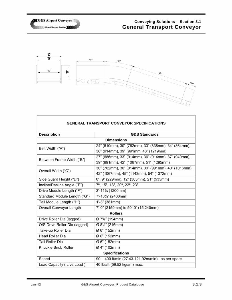
Belt Width (“A”) 24” (610mm), 30” (762mm), 33” (838mm), 34” (864mm),
36” (914mm), 39” (991mm, 48” (1219mm)
Between Frame Width (“B”) 27” (686mm), 33” (914mm), 36” (914mm), 37” (940mm),
39” (991mm), 42” (1067mm), 51” (1295mm)
Overall Width (“C”) 30” (762mm), 36” (914mm), 39” (991mm), 40” (1016mm),
42” (1067mm), 45” (1143mm), 54” (1372mm)
Side Guard Height (“D”) 0”, 9” (229mm), 12” (305mm), 21” (533mm)
Incline/Decline Angle (“E”) 7º, 15º, 18º, 20º, 22º, 23º
Drive Module Length (“F”) 3’-11¼ (1200mm)
Standard Module Length (“G”) 7’-10½” (2400mm)
Tail Module Length (“H”) 1’-3” (381mm)
Overall Conveyor Length 7’-0” (2159mm) to 50’-0” (15,240mm)
Rollers
Drive Roller Dia (lagged) Ø 7⅝” (194mm)
O/S Drive Roller Dia (lagged) Ø 8½” (216mm)
Take-up Roller Dia Ø 6” (152mm)
Head Roller Dia Ø 6” (152mm)
Tail Roller Dia Ø 6” (152mm)
Knuckle Snub Roller Ø 4” (102mm)
Specifications
Speed 90 – 400 ft/min (27.43-121.92m/min) –as per specs
Load Capacity ( Live Load ) 40 lbs/ft (59.52 kgs/m) max.
Conveying Solutions – Section 3.1
General Transport Conveyor
Jan-12 G&S Airport Conveyor: Product Catalogue 3.1.4
Drive Options
Application Standard Optional
Make Model Make Model
90 Deg.
Reducer SEW Eurodrive
ST – TorqLOC SA – Hollow Shaft
Morse
Dodge Ti-Gear
Motorized
Pulley
Van Der Graaf BDL DuraDrive
Interoll
Conventional
Belt Drive
Baldor (motor)
Reliance (motor)
Dodge (speed
reducer)
TXT
Belting Options
Application Standard Optional
Make Model Make Model
Public View;
Load/Unload,
Transport;
Level - 7º
Inc/Dec
Nitta BLC-12A Ammeraal Beltech PHR 2-220 1/32 x
Bare FR
Habasit NHM-8ESBV
Siegling America E8/2 U0VSH MT-FR
Black
Non-Public View;
Load/Unload,
Transport;
Level -7º
Inc/Dec
Nitta BLC-18DKF2 Ammeraal Beltech EX 10/2 0+00 AS
FR
Habasit NNT-10ESBU
Siegling America E12/2 V1/V1 M-FR
Black
Non-Public
View; Inc/Dec
> 7º
Nitta BLRB-16A Ammeraal Beltech EX 10/2 0+A32
Black AS FR
Habasit NSL-11ESBV
Siegling America E8/2 U0/V15 LG-FR
***Refer to motor manifest for specific belt and drive types used
judy
TextBox
Jan-12

***NOTE: EXTERNALLY MOUNTED FLANGE BEARINGS ARE ALSO AVAILABLE.
1 Tail Chassis2 Tail Flank Plate3 Deckpan4 Tail Roller (Crowned)5 Jacking Bolt6 Roller Shaft7 Internal Piloted Flange Bearing8 Bearing Mounting Plate
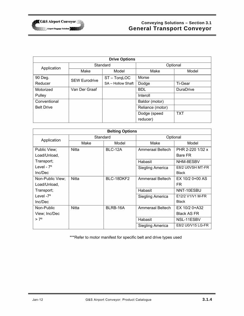
ITEM COMPONENT
EXPLODED ROLLER ASSEMBLYSCALE: 1:10
6
7
8
4
48" (1219mm)
30" (762mm) 33" (838mm) 36" (914mm)
OVERSIZE
Other Belt Widths Available with Extended Lead Times.
BELT WIDTHS
NOTE: No Allowance Made For Baggage Load, Overhead Supports, Catwalks, Maintenance Platforms And Live Load For Maintenance.
47 (17.54) 50 (18.66) 53 (19.78)
OVERSIZE 390 (858)
PER LINEAR FOOT
36" (914mm) 39" (991mm) 40" (1016mm) 42" (1067mm)
64 (141)
OVERALLWIDTH ("X")
54" (1372mm)
STANDARD
141 (310)
CONCENTRATION AT TAIL END
300 (111.97) 315 (117.57) 330 (123.17)
MASS in LBS (kgs)
STANDARD
CONCENTRATION AT HEAD/DRIVE
62 (23.14) 66 (24.63) 81 (30.23)
15.000 [381mm]
"X"
SEE EXPLODED ROLLER ASSEMBLY
2
5
1
3
4
***NOTE: EXTERNALLY MOUNTED FLANGE BEARINGS ARE ALSO AVAILABLE.
G&S Airport Conveyor: Product Catalogue
PROPRIETARY AND CONFIDENTIAL: The information contained in this drawing is the sole property of G&S Airport Conveyor. Any reproduction in part or as a whole without the written permission of G&S Airport Conveyor is prohibited. G&S Airport Conveyor reserves the right to change drawings at any time.
Conveying Solutions - Section 3.1General Transport Conveyor
GENERAL TRANSPORT TAIL MODULE
04/19/05 3.1.6
judy
TextBox
Jan-12

judy
TextBox
Jan-12

PER LINEAR FOOT
390 (858)
OVERSIZE
47 (17.54) 50 (18.66) 53 (19.78)
NOTE: No Allowance Made For Baggage Load, Overhead Supports, Catwalks, Maintenance Platforms And Live Load For Maintenance.
Other Belt Widths Available with Extended Lead Times .
OVERSIZE 48" (1219mm)
OVERALLWIDTH ("X")
BELT WIDTHS
STANDARD
54" (1372mm)
64 (141)
36" (914mm) 39" (991mm) 40" (1016mm) 42" (1067mm)
30" (762mm) 33" (838mm) 34" (864mm) 36" (914mm)
62 (23.14) 66 (24.63) 81 (30.23)
MASS in LBS (kgs)CONCENTRATION AT HEAD/DRIVESTANDARD
300 (111.97) 315 (117.57) 330 (123.17) 141 (310)
CONCENTRATION AT TAIL END
ITEM COMPONENT1 Drive Chassis2 Drive Roller, Lagged3 Head Roller4 Snub Roller5 Take-up Roller6 Drive Flank Plate7 Head Flank Plate8 Take-Up Flank Plate9 Belt Take-up Assembly10 Deckpan11 Bearing12 Shaft Mount Motor/Gearbox Assembly*13 Torque Arm14 Torque Arm Brackets
*Can Be Equipped with a Variable Frequency Drive (VFD) for Indexing Applications.
10
12
13
14
1
4
3
7
6 118
5
2
9
G&S Airport Conveyor: Product Catalogue
PROPRIETARY AND CONFIDENTIAL: The information contained in this drawing is the sole property of G&S Airport Conveyor. Any reproduction in part or as a whole without the written permission of G&S Airport Conveyor is prohibited. G&S Airport Conveyor reserves the right to change drawings at any time.
Conveying Solutions - Section 3.1General Transport Conveyor
GENERAL TRANSPORT DRIVE UNIT C/W MOTOR/GEARBOX
04/19/05 3.1.8
judy
TextBox
Jan-12
PER LINEAR FOOT
390 (858)
OVERSIZE
47 (17.54) 50 (18.66) 53 (19.78)
NOTE: No Allowance Made For Baggage Load, Overhead Supports, Catwalks, Maintenance Platforms And Live Load For Maintenance.
Other Belt Widths Available with Extended Lead Times .
OVERSIZE 48" (1219mm)
OVERALLWIDTH ("X")
BELT WIDTHS
STANDARD
54" (1372mm)
64 (141)
36" (914mm) 39" (991mm) 40" (1016mm) 42" (1067mm)
30" (762mm) 33" (838mm) 34" (864mm) 36" (914mm)
62 (23.14) 66 (24.63) 81 (30.23)
MASS in LBS (kgs)CONCENTRATION AT HEAD/DRIVESTANDARD
300 (111.97) 315 (117.57) 330 (123.17) 141 (310)
CONCENTRATION AT TAIL END
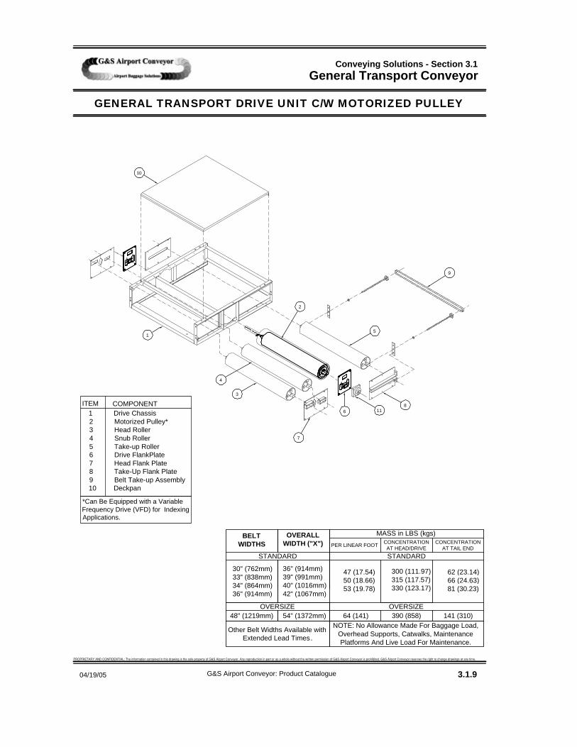
1 Drive Chassis2 Motorized Pulley*3 Head Roller4 Snub Roller5 Take-up Roller6 Drive FlankPlate7 Head Flank Plate8 Take-Up Flank Plate9 Belt Take-up Assembly10 Deckpan
COMPONENTITEM
*Can Be Equipped with a Variable Frequency Drive (VFD) for Indexing Applications.
1
4
3
7
6 118
5
2
9
10
G&S Airport Conveyor: Product Catalogue
PROPRIETARY AND CONFIDENTIAL: The information contained in this drawing is the sole property of G&S Airport Conveyor. Any reproduction in part or as a whole without the written permission of G&S Airport Conveyor is prohibited. G&S Airport Conveyor reserves the right to change drawings at any time.
Conveying Solutions - Section 3.1General Transport Conveyor
GENERAL TRANSPORT DRIVE UNIT C/W MOTORIZED PULLEY
04/19/05 3.1.9
judy
TextBox
Jan-12

judy
TextBox
Jan-12

judy
TextBox
Jan-12

judy
TextBox
Jan-12

Conveying Solutions – Section 3.2
Power Turns
Jan-12 G&S Airport Conveyor: Product Catalogue 3.2.1
ADVANTAGES:
Smooth Baggage Transfer
High Speed Capacity
Low Noise
Low Maintenance
Rugged Construction
Product Orientation OVERVIEW: Power turn conveyors transfer baggage smoothly and efficiently around curves without changing or affecting the orientation of the baggage relative to the conveying surface. Positioned adjacent to other conveyors, they accommodate baggage flow by providing a gentle, effective change in baggage direction. Available for all standard widths, power turns are manufactured in angular increments from 15° to 209°. G&S Airport Conveyor utilizes both Portec Sigma® Belt power turns and Transnorm System Inc. power turns.
DRIVE G&S Airport Conveyor drives all Sigma® Belt power turns using integral motor / gearbox reducers; optional drive methods are available. INSTALLATION G&S Airport Conveyor site representatives have extensive installation experience using power turn conveyors, and are experts at installing and maintaining this equipment.

Conveying Solutions – Section 3.3
Spiral Power Turns
Jan-12 G&S Airport Conveyor: Product Catalogue 3.3.1
ADVANTAGES:
Achieves Elevation and Direction Flow Changes
Smooth Baggage Transfer
High Speed Capacity
Low Noise
Low Maintenance
Rugged Construction OVERVIEW: Spiral power turn conveyors transfer baggage smoothly and efficiently around curves and through elevation differentials without affecting the orientation of the baggage relative to the conveying surface. Positioned adjacent to other conveyors, they accommodate baggage transfer by simultaneously inclining or declining flow while changing baggage direction. Available for all standard widths, spiral power turns are manufactured in angular increments from 15° to 209°. G&S Airport utilizes Spiral-Curve® power turns, manufactured by Portec, as well as power-turns manufactured by Transnorm Systems Inc.
DRIVE G&S Airport Conveyor drives all Spiral-Curve® power turns using integral 90˚ motor / gearbox reducers; optional drive methods are available. INSTALLATION All G&S Airport Conveyor site representatives have extensive installation experience using power turn conveyors, and are experts at installing and maintaining this equipment.