
General Specifications - Yokogawa Electric · 2 General Specifications ... Model Suffix Option...
8
Model PR10 Contacting Conductivity Retractable fitting General Specifications GS 12D7J4-02E-E 3rd Edition On-line measurements often present extra challenges, especially when routine maintenance is required. The PR10 is ideally suitable for applications where the sensors must be removed without interrupting or shutting down the process. Without any special tools the PR10 can be retracted safely from the process at pressures up to 5 bar. For ease of use optional flush ports are available. In the retracted position the sensor can be kept moist, cleaned or even calibrated. This can all be done without process interruption or disassembly of the armature. Features • One model for pH, conductivity and inductive conductivity sensors • Build in scraper to avoid contamination of the fitting • Usable for wide range of sensors • A safe “through the valve” insertion and retraction design • Simplified installation by optional ball valves with flanged or tapered connections • Optional flush port for keeping moist, cleaning and calibration
Transcript of General Specifications - Yokogawa Electric · 2 General Specifications ... Model Suffix Option...

Model PR10Contacting ConductivityRetractable fitting
GeneralSpecifications
GS 12D7J4-02E-E3rd Edition
On-line measurements often present extra challenges, especially when routine maintenance is required. The PR10 is ideally suitable for applications where the sensors must be removed without interrupting or shutting down the process. Without any special tools the PR10 can be retracted safely from the process at pressures up to 5 bar.
For ease of use optional flush ports are available. In the retracted position the sensor can be kept moist, cleaned or even calibrated. This can all be done without process interruption ordisassembly of the armature.
Features• One model for pH, conductivity and inductive conductivity
sensors• Build in scraper to avoid contamination of the fitting• Usable for wide range of sensors • A safe “through the valve” insertion and retraction design• Simplified installation by optional ball valves with flanged or
tapered connections• Optional flush port for keeping moist, cleaning and calibration

GS 12D7J4-02E-E
2
General Specifications
A. Wetted materials - For sensor check Instruction Manual - Stainless steel AISI 316L - O-ring seals: Viton 70° shore
B. Non-wetted materials - For sensor check Instruction Manual - Stainless steel AISI 316, 304 - Polypropylene glass filled
C. Insertion length - Ref. mechanical drawing page 4.
D. Pressure/temperature ratings - Static conditions: see Figure. 1. - Operating conditions during extraction and insertion max.
500kPa, max. 100°C
E. Flange ratings: - DIN flange DN32 PN10 - ANSI flange 1¼“ 150 lbs - DIN flange DN50 PN10 - ANSI flange 2“ 150 lbs
Fig. 1 Pressure / Temperature graphic
F. Specifications of the sensor used - Please check sensor specifications
G. Weight - Approx 2.5 kg excl. ball valve
H. Specifications of the SC4A-PR Wetted Parts Body & electrodes : SS AISI 316 or Titanium grade 2 or 3 O-ring : Viton Mounting adapter : PR10 nsulations : PEEK (Poly Ether Ether Ketone)
I. Operating Specifications Measuring system : 2-electrode Maximum pressure : 10 bar (142 PSIg) Maximum temp. : 110ºC (230 °F) Temp. response : < 1 minute for 90% of a step change Sterilize : At 135°C (275 °F)
0 10 20 30 40 50 60 70 80 100 120 140 160
bar
2
4
6
8
10
12AISI 316
GS 12D7J4-02E-E
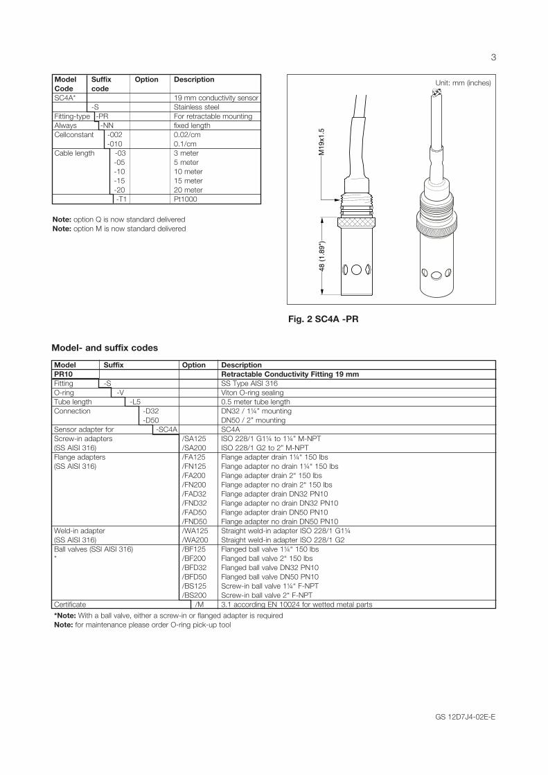
Fig. 2 SC4A -PR M
19x1
.548
(1.8
9")
Unit: mm (inches) Model Suffix Option Description Code code SC4A* 19 mm conductivity sensor -S Stainless steel Fitting-type -PR For retractable mounting Always -NN fixed length Cellconstant -002 0.02/cm -010 0.1/cm Cable length -03 3 meter -05 5 meter -10 10 meter -15 15 meter -20 20 meter -T1 Pt1000
Note: option Q is now standard deliveredNote: option M is now standard delivered
Model- and suffix codes
Model Suffix Option Description PR10 Retractable Conductivity Fitting 19 mm Fitting -S SS Type AISI 316 O-ring -V Viton O-ring sealingTube length -L5 0.5 meter tube lengthConnection -D32 DN32 / 1¼” mounting -D50 DN50 / 2” mountingSensor adapter for -SC4A SC4AScrew-in adapters /SA125 ISO 228/1 G1¼ to 1¼” M-NPT (SS AISI 316) /SA200 ISO 228/1 G2 to 2” M-NPTFlange adapters /FA125 Flange adapter drain 1¼“ 150 lbs (SS AISI 316) /FN125 Flange adapter no drain 1¼“ 150 lbs /FA200 Flange adapter drain 2“ 150 lbs /FN200 Flange adapter no drain 2“ 150 lbs /FAD32 Flange adapter drain DN32 PN10 /FND32 Flange adapter no drain DN32 PN10 /FAD50 Flange adapter drain DN50 PN10 /FND50 Flange adapter no drain DN50 PN10Weld-in adapter /WA125 Straight weld-in adapter ISO 228/1 G1¼ (SS AISI 316) /WA200 Straight weld-in adapter ISO 228/1 G2Ball valves (SSl AISI 316) /BF125 Flanged ball valve 1¼“ 150 lbs * /BF200 Flanged ball valve 2“ 150 lbs /BFD32 Flanged ball valve DN32 PN10 /BFD50 Flanged ball valve DN50 PN10 /BS125 Screw-in ball valve 1¼“ F-NPT /BS200 Screw-in ball valve 2“ F-NPTCertificate /M 3.1 according EN 10024 for wetted metal parts
*Note: With a ball valve, either a screw-in or flanged adapter is requiredNote: for maintenance please order O-ring pick-up tool
3

GS 12D7J4-02E-E
Dimensions
Fig. 3 Dimensional drawing PR10...-D32 with mounted SC4A sensor
unit mm (inches)
PR10-S-V-L5-D32-SC4A
PR10-..-..-....-D32-SC4A/F..125/BF125PR10-..-..-....-D32-SC4A/F..D32/BFD32
PR10-..-..-....-D32-SC4A/SA125/BS125
Dimensional drawing PR10...-D32 with mounted SC4A sensor
529 (20.8")
54 (2.15”)
423 (16.7")
390 (15.35")
110 (4.35”)
779 (30.7")
unit mm (inches)
4
GS 12D7J4-02E-E
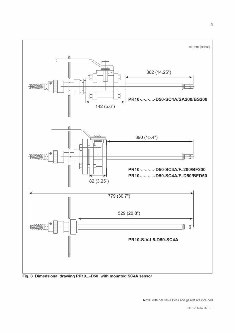
Fig. 3 Dimensional drawing PR10...-D50 with mounted SC4A sensor
Note: with ball valve Bolts and gasket are included
PR10-S-V-L5-D50-SC4A
PR10-..-..-....-D50-SC4A/F..200/BF200PR10-..-..-....-D50-SC4A/F..D50/BFD50
PR10-..-..-....-D50-SC4A/SA200/BS200
Dimensional drawing PR10...-D50 with mounted SC4A sensor
529 (20.8")
390 (15.4")
362 (14.25")
82 (3.25”)
142 (5.6”)
779 (30.7")
unit mm (inches)
5

GS 12D7J4-02E-E
Op
tio
ns P
R10
Fig
. 5 D
imen
sio
ns o
f th
e P
R10
op
tio
ns
Tab
le 2
Dim
ensi
ons
op
tio
ns in
mm
(in
ches
)O
pti
on
Des
crip
tio
n Fi
g.
A
B
L C
B
b
D
E
Di
Dg
K
/S
A12
5 IS
O 2
28/1
G1¼
to
1¼”
M-N
PT
A
ISO
228
/1 -
G1¼
1¼
” N
PT
60 (2
.4)
/SA
200
ISO
228
/1 G
2 to
2”
M-N
PT
A
ISO
228
/1 -
G2
2” N
PT
58 (2
.3)
/FA
125
Flan
ge a
dapt
er d
rain
1¼
” 15
0 Lb
s D
, G
IS
O 2
28/1
- G
1¼
69.5
(2.7
) 66
(2.6
) 29
(1.1
) 15
.7 (0
.6)
117.
3 (4
.6)
1/8”
NP
T 47
(1.9
) 15
.7 (0
.6)
88.9
(3.5
)/F
N12
5 Fl
ange
ada
pter
no
drai
n 1¼
” 15
0 Lb
s C
, G
IS
O 2
28/1
- G
1¼
69.5
(2.7
) 66
(2.6
) 29
(1.1
) 15
.7 (0
.6)
117.
3 (4
.6)
47
(1.9
) 15
.7 (0
.6)
88.9
(3.5
)/F
A20
0 Fl
ange
ada
pter
dra
in 2
” 15
0 Lb
s D
, G
IS
O 2
28/1
- G
2 10
1 (4
) 77
(3)
32 (1
.3)
25 (1
) 16
5 (6
.5)
1/8”
NP
T 73
(2.9
) 19
(0.7
) 12
0-12
5 (4
.7)-
(4.9
)/F
N20
0 Fl
ange
ada
pter
no
drai
n 2”
150
Lbs
C
, G
IS
O 2
28/1
- G
2 10
1 (4
) 54
(2.1
) 32
(1.3
) 25
(1)
165
(6.5
)
73 (2
.9)
19 (0
.7)
120-
125
(4.7
)-(4
.9)
/FA
D32
Fl
ange
ada
pter
dra
in D
N32
PN
10
D ,
G
ISO
228
/1 -
G1¼
69
.5 (2
.7)
66 (2
.6)
29 (1
.1)
16 (0
.6)
140
(5.5
) 1/
8” N
PT
47 (1
.9)
18 (0
.7)
100
(3.9
)/F
ND
32
Flan
ge a
dapt
er n
o dr
ain
DN
32 P
N10
C
, G
IS
O 2
28/1
- G
1¼
69.5
(2.7
) 66
(2.6
) 29
(1.1
) 16
(0.6
) 14
0 (5
.5)
47
(1.9
) 18
(0.7
) 10
0 (3
.9)
/FA
D50
Fl
ange
ada
pter
dra
in D
N50
PN
10
D ,
G
ISO
228
/1 -
G2
101
(4)
77 (3
) 32
(1.3
) 25
(1)
165
(6.5
) 1/
8” N
PT
73 (2
.9)
19 (0
.7)
120-
125
(4.7
)-(4
.9)
/FN
D50
Fl
ange
ada
pter
no
drai
n D
N50
PN
10
C ,
G
ISO
228
/1 -
G2
101
(4)
54 (2
.1)
32 (1
.3)
25 (1
) 16
5 (6
.5)
73
(2.9
) 19
(0.7
) 12
0-12
5 (4
.7)-
(4.9
)/W
A12
5 S
trai
ght
wel
d-in
ada
pter
ISO
228
/1 G
1¼
B
ISO
228
/1 -
G1¼
42
(1.7
) 45
(1.8
)
/W
A20
0 S
trai
ght
wel
d-in
ada
pter
ISO
228
/1 G
2 B
IS
O 2
28/1
- G
2 49
(1.9
) 45
(1.8
)
/B
F125
B
all-v
alve
flan
ged
1¼”
150
Lbs
F
54
(2.1
)
11
8 (4
.6)
32
(1.3
) M
14
89 (3
.5)
/BF2
00
Bal
l-val
ve fl
ange
d 2”
150
Lbs
F
82 (3
.2)
150
(5.9
)
50 (2
) M
16
121
(4.8
)/B
FD32
B
all-v
alve
flan
ged
DN
32 P
N10
F
54 (2
.1)
140
(5.5
)
32 (1
.3)
M16
10
0 (3
.9)
/BFD
50
Bal
l-val
ve fl
ange
d D
N50
PN
10
F
82
(3.2
)
16
5 (6
.5)
50
(2)
M16
12
5 (4
.9)
/BS
125
Bal
l-val
ve s
crew
-in 1
¼”
F-N
PT
E
1¼”
NP
T
110
(4.3
)
32
(1.3
)/B
S20
0 B
all-v
alve
scr
ew-in
2”
F-N
PT
E
2” N
PT
14
2 (5
.6)
50 (2
)
EAB
CD
FG
A
L
B
LA B
L
C
A
L
B
Bb
DDi
Dg K
A
L
B
E
DKDi
L
Dg
ADi
EAB
CD
FG
A
L
B
LA B
L
C
A
L
B
Bb
DDi
Dg K
A
L
B
E
DKDi
L
Dg
ADi
EAB
CD
FG
A
L
B
LA B
L
C
A
L
B
Bb
DDi
Dg K
A
L
B
E
DKDi
L
Dg
ADi
EAB
CD
FG
A
L
B
LA B
L
C
A
LB
Bb
DDi
Dg K
A
L
B
E
DKDi
L
Dg
ADi
EAB
CD
FG
A
L
B
LA B
L
C
A
L
B
Bb
DDi
Dg K
A
L
B
E
DKDi
L
Dg
ADi
EAB
CD
FG
A
L
B
LA B
L
C
A
L
B
Bb
DDi
Dg K
A
L
B
E
DKDi
L
Dg
ADi
EAB
CD
FG
A
L
B
LA B
L
C
A
L
B
Bb
DDi
Dg K
A
L
B
E
DKDi
L
Dg
ADi
EAB
CD
FG
A
L
B
LA B
L
C
A
L
B
Bb
DDi
Dg K
A
L
B
E
DKDi
L
Dg
ADi
6
GS 12D7J4-02E-E
Table 3 Spareparts
Part no. DescriptionK1525AP Adapter SC4A - ISC40K1525AA Outer tubeK1525AF O-ring pick up toolK1525BA O-ring set PR10-S-V-L5-D32K1525BB O-ring set PR10-S-V-L5-D50K1525BC Key setK1525BD Squeezing setK1525BE Set M16 bolt & washer (8 pcs)K1525BF Set M14 bolt & washer (8 pcs)K1525BG Gaskets ball valves - D50 + 2”K1525BH Gaskets ball valves - D32 + 1¼”K1525YA PR10/SA125K1525YB PR10/FA125K1525YC PR10/FN125K1525YD PR10/FA200 - FAD50K1525YE PR10/FN200 - FND50K1525YF PR10/FAD32K1525YG PR10/FND32K1525YH PR10/WA125K1525YJ PR10/WA200K1525YK PR10/BF125K1525YL PR10/BF200K1525YM PR10/BFD32K1525YN PR10/BFD50K1525YP PR10/BS125K1525YQ PR10/BS200K1541EM Adapter 2” NPT-G2 SS (ISC40PR/B)
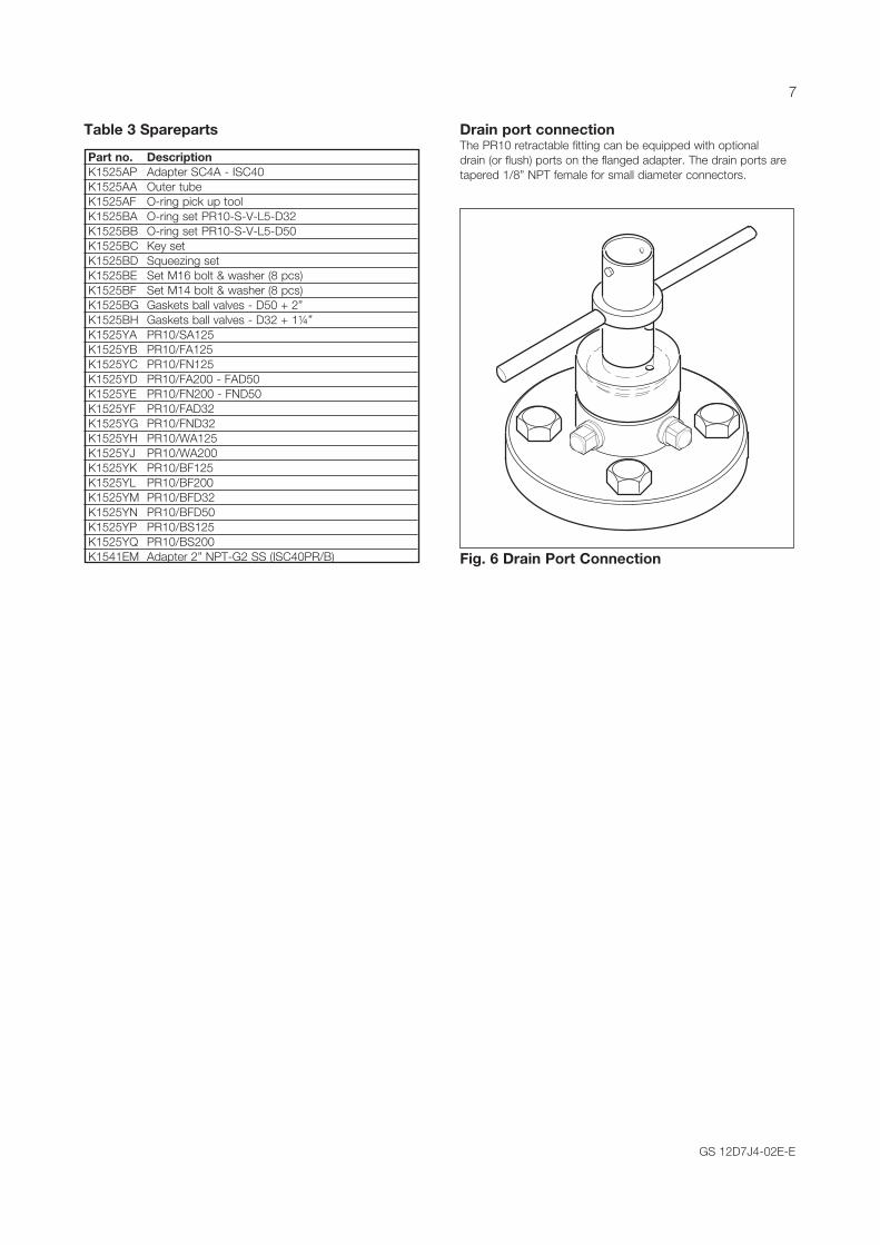
Drain port connection The PR10 retractable fitting can be equipped with optional drain (or flush) ports on the flanged adapter. The drain ports are tapered 1/8” NPT female for small diameter connectors.
Fig. 6 Drain Port Connection
7

GS 12D7J4-02E-ESubject to change without notice Printed in The Netherlands, 3-1008 (A) ICopyright©
GS 12X0X0-E-ESubject to change without notice Printed in The Netherlands, 00-000 (A) ICopyright ©
Yokogawa has an extensive sales and distribution network. Please refer to the European website (www.yokogawa.com/eu) to contact your nearest representative.
Euroweg 23825 HD AmersfoortThe Netherlandswww.yokogawa.com/eu
YOKOGAWA ELECTRIC CORPORATIONWorld Headquarters9-32, Nakacho 2-chome, Musashino-shiTokyo 180-8750Japanwww.yokogawa.com
YOKOGAWA CORPORATION OF AMERICA2 Dart RoadNewnan GA 30265USAwww.yokogawa.com/us
YOKOGAWA ELECTRIC ASIA Pte. LTD.5 Bedok South RoadSingapore 469270Singaporewww.yokogawa.com/sg
YOKOGAWA CHINA CO. LTD.3F Tower D Cartelo Crocodile BuildingNo.568 West Tianshan Road Changing DistrictShanghai, Chinawww.yokogawa.com/cn
YOKOGAWA MIDDLE EAST B.S.C.(c)P.O. Box 10070, ManamaBuilding 577, Road 2516, Busaiteen 225Muharraq, Bahrainwww.yokogawa.com/bh


