General Specifications SSS7710, SSS7720 Plant …‡庆横河川仪有限公司... · General...
26
General Specifications <<Contents>> <<Index>> Models SSS7700, SSS7710, SSS7720 Plant Resource Manager Yokogawa Electric Corporation 2-9-32, Nakacho, Musashino-shi, Tokyo, 180-8750 Japan Tel.: 81-422-52-5634 Fax.: 81-422-52-9802 GS 33Y05Q10-31E GS 33Y05Q10-31E ©Copyright Jan. 2001 12th Edition Nov.7,2005 ■ GENERAL PRM is a dynamic software tool that supports the daily business activities of maintenance personnel. This Plant Resource Manager Package for the digital network era of fieldbus efficiently handles field device management and maintenance work for the FOUNDATION fieldbus and HART devices, which helps reduce Total Cost of Ownership (TCO) in your plant. This package also can support conventional analog devices with manual registration; it can provide integrated manage- ment of conventional analog, FOUNDATION fieldbus and HART devices. PRM R2.02 or later version supports communication with HART devices. ■ FUNCTION SPECIFICATIONS Plant Resource Manager (PRM) consists of the following components: ● PRM Server • Uses the popular, industrial-strength Oracle database. • Maintains a historical record of device parameters, Inspection Schedule and Inspection Memo. • Implements centralized management of device information such as the device list, inspection record and schedule, user- created electronic documents, and parts lists. • Can generate the best suited maintenance alarms inside or outside of the PRM system using a maintenance alarm function (*1). This function can acquire the information necessary to diagnose the statuses of various field devices that have been defined and registered in advance. This function can not only acquire device events (e.g., device block alarms) but also generate maintenance alarms for necessary information (phenomena, causes, action) added to acquired device events, and can distribute this maintenance alarm information to personnel who want it. *1: Supported by PRM R2.10 or later version. ● PRM Client • User-friendly Windows-based operating environment, with Explorer-like “Navigator” for selecting a specific device. • Uses bidirectional, all-digital field networks such as FOUNDATION fieldbus. Performs automatic device recognition and registration (Plug and Play), monitors device health statuses with maintenance alarm functions, monitors communication error, monitors advanced diagnosis of device, process interface diagnosis and Unit diagnosis, etc. by PRM Advanced Diagnosis application, allows tuning of device parameters, and performs device diagnosis (DD Menu, DeviceViewer, PLUG-IN Application, etc.). • Online device adjustment/setting from the PRM Client can be performed on the screen with the same user interface as that of on-site adjustment setting tool FieldMate. • The status display icon appears beside the device icon changes depending on communication and device status. This provides an easy-to-understand overview of device health status. • For a device with an unconfirmed maintenance alarm status (device health status), a confirmation status icon appears next to the device icon. • The user can freely define the device icon displayed in the device navigator. Moreover, the user can select one from three sizes of icons and fonts, and can customize the characters and the icons according to the screen size or on the user’s request. • In addition to Maintenance Alarm Function and standard diagnostic functions, Yokogawa provides Acquisition Navigator and Diagnostic Tool as components of the PRM Advanced Diagnosis package. With these software components, you can carry out advanced predictive, proactive and preventive maintenance using a field network. • Allows not merely FOUNDATION fieldbus-compliant devices and HART-compliant devices but also conventional analog field devices to be registered together for true, centralized device management. • Allows using the third-party, such as device vendors, software as a PLUG-IN Application in addition to Yokogawa’s product, DeviceViewer (*1) (*2) and PLUG-IN ValveNavi (*1). PRM Client can start up a calibration tool or a diagnosis tool that is uniquely designed by device vendors as PLUG-IN Application. *1: PRM R2.03 or later version supports the DeviceViewer for FOUNDATION fieldbus devices and PRM R2.06 or later version supports the DeviceViewer for HART-devices. *2: DeviceViewer is a build-in PLUG-IN Application for self-diagnostic of FOUNDATION fieldbus devices and HART devices into PRM Client. The way to use the product differs from regular PLUG-IN Application. To be able to run the DeviceViewer of a device from each vendor, definition files must be obtained from that device vendor.
Transcript of General Specifications SSS7710, SSS7720 Plant …‡庆横河川仪有限公司... · General...

GeneralSpecifications
<<Contents>> <<Index>>
Models SSS7700,SSS7710, SSS7720Plant Resource Manager
Yokogawa Electric Corporation2-9-32, Nakacho, Musashino-shi, Tokyo, 180-8750 JapanTel.: 81-422-52-5634 Fax.: 81-422-52-9802
GS 33Y05Q10-31E
GS 33Y05Q10-31E©Copyright Jan. 2001
12th Edition Nov.7,2005
■ GENERALPRM is a dynamic software tool that supports the daily business activities of maintenance personnel. This Plant ResourceManager Package for the digital network era of fieldbus efficiently handles field device management and maintenance workfor the FOUNDATION fieldbus and HART devices, which helps reduce Total Cost of Ownership (TCO) in your plant.
This package also can support conventional analog devices with manual registration; it can provide integrated manage-ment of conventional analog, FOUNDATION fieldbus and HART devices.
PRM R2.02 or later version supports communication with HART devices.
■ FUNCTION SPECIFICATIONSPlant Resource Manager (PRM) consists of the following components:
● PRM Server• Uses the popular, industrial-strength Oracle database.• Maintains a historical record of device parameters, Inspection Schedule and Inspection Memo.• Implements centralized management of device information such as the device list, inspection record and schedule, user-
created electronic documents, and parts lists.• Can generate the best suited maintenance alarms inside or outside of the PRM system using a maintenance alarm
function (*1). This function can acquire the information necessary to diagnose the statuses of various field devices thathave been defined and registered in advance. This function can not only acquire device events (e.g., device block alarms)but also generate maintenance alarms for necessary information (phenomena, causes, action) added to acquired deviceevents, and can distribute this maintenance alarm information to personnel who want it.
*1: Supported by PRM R2.10 or later version.
● PRM Client• User-friendly Windows-based operating environment, with Explorer-like “Navigator” for selecting a specific device.• Uses bidirectional, all-digital field networks such as FOUNDATION fieldbus. Performs automatic device recognition and
registration (Plug and Play), monitors device health statuses with maintenance alarm functions, monitors communicationerror, monitors advanced diagnosis of device, process interface diagnosis and Unit diagnosis, etc. by PRM AdvancedDiagnosis application, allows tuning of device parameters, and performs device diagnosis (DD Menu, DeviceViewer,PLUG-IN Application, etc.).
• Online device adjustment/setting from the PRM Client can be performed on the screen with the same user interface as thatof on-site adjustment setting tool FieldMate.
• The status display icon appears beside the device icon changes depending on communication and device status. Thisprovides an easy-to-understand overview of device health status.
• For a device with an unconfirmed maintenance alarm status (device health status), a confirmation status icon appears nextto the device icon.
• The user can freely define the device icon displayed in the device navigator.Moreover, the user can select one from three sizes of icons and fonts, and can customize the characters and the iconsaccording to the screen size or on the user’s request.
• In addition to Maintenance Alarm Function and standard diagnostic functions, Yokogawa provides Acquisition Navigatorand Diagnostic Tool as components of the PRM Advanced Diagnosis package. With these software components, you cancarry out advanced predictive, proactive and preventive maintenance using a field network.
• Allows not merely FOUNDATION fieldbus-compliant devices and HART-compliant devices but also conventional analog fielddevices to be registered together for true, centralized device management.
• Allows using the third-party, such as device vendors, software as a PLUG-IN Application in addition to Yokogawa’sproduct, DeviceViewer (*1) (*2) and PLUG-IN ValveNavi (*1). PRM Client can start up a calibration tool or a diagnosis toolthat is uniquely designed by device vendors as PLUG-IN Application.
*1: PRM R2.03 or later version supports the DeviceViewer for FOUNDATION fieldbus devices and PRM R2.06 or later version supportsthe DeviceViewer for HART-devices.
*2: DeviceViewer is a build-in PLUG-IN Application for self-diagnostic of FOUNDATION fieldbus devices and HART devices into PRMClient. The way to use the product differs from regular PLUG-IN Application. To be able to run the DeviceViewer of a device fromeach vendor, definition files must be obtained from that device vendor.
2
All Rights Reserved. Copyright © 2001, Yokogawa Electric Corporation
<<Contents>> <<Index>>
GS 33Y05Q10-31E
● Field Communications ServerPRM supports two types of field communication (Foudation fieldbus and HART).
PRM can communicate with FF devices via FF communication module in CENTUM system and in STARDOM system.
When connecting to HART devices, two system configuration types are available.
One is Control bus connection via AI/AO modules with HART Communication in CENTUM CS 3000 system and in STAR-DOM System. Another one is Serial port connection via 3rd Vendor HART Multiplexer. For serial port connection, PRMsupports HART multiplexers supplied from four vendors (P+F, MTL, ELCON and STAHL). HART modem and HARTmultiplexer can be connected to the multiple COM ports at the same time. By using serial port connection, PRM can be easilyadded on existing HART system.
Supported Configuration• FF communication modules for CS 1000/CS 3000• AI/AO Modules with HART Communication for CS 3000• FF communication modules for STARDOM• AI/AO Modules with HART Communication for STARDOM• 3rd vendor HART Multiplexer
● Interface to Computerized Maintenance Management System (Option)Plant Resource Manager (PRM) supports interface with MAXIMO, a Computerized Maintenance Management System(CMMS) provided by MRO Software, Inc. This enables PRM to connect with the CMMS and to provide information online.More effective maintenance operation can be achieved by this feature. For details of Interface to Computerized MaintenanceManagement System, see GS 33Y05Q20-31E “SSS7730 Interface for CMMS”.
● PRM Advanced Diagnosis (Option)PRM Advanced Diagnostic Server is an optional package available with PRM. It provides an environment for executing thediagnostic algorithm of field devices.
With this package, you can directly acquire parameters from these devices at fixed intervals. By using diagnostic algorithmapplications, you can execute diagnosis with the acquired parameters for possible anomalies.
By using PRM Advanced Diagnostic Application Software Development Kit (PAA-SDK) in addition to the package, you caneasily create and execute diagnostic applications containing advanced diagnostic algorithms for process interface, loop andunit that have been difficult to realize with field devices alone.
Note that PRM advanced diagnostic applications (PAA) are available as diagnostic applications initially provided by devicevendors or third-party vendors. For details of PRM Advanced Diagnosis, see GS 33Y05Q21-31E “SSS7740 PRM AdvancedDiagnostic Server”.
● Multi-server SwitchoverThe scope of PRM management generally corresponds to a CS 1000/CS 3000 project or STARDOM project.
However, if a wider range of integrated management is required, multi-server functions can be used to dynamically switch thePRM server that is referenced by a PRM client. This allows centralized remote monitoring of large-scale plants with someCENTUM projects.
Nov.7,2005-00
3<<Contents>> <<Index>>
All Rights Reserved. Copyright © 2001, Yokogawa Electric Corporation GS 33Y05Q10-31E Nov.7,2005-00
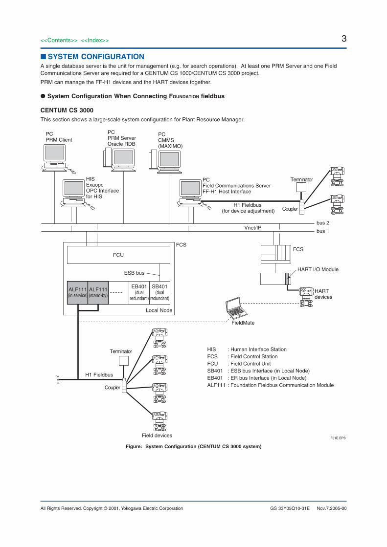
■ SYSTEM CONFIGURATIONA single database server is the unit for management (e.g. for search operations). At least one PRM Server and one FieldCommunications Server are required for a CENTUM CS 1000/CENTUM CS 3000 project.
PRM can manage the FF-H1 devices and the HART devices together.
● System Configuration When Connecting FOUNDATION fieldbus
CENTUM CS 3000This section shows a large-scale system configuration for Plant Resource Manager.
HISExaopcOPC Interface for HIS
PCField Communications ServerFF-H1 Host Interface
PCPRM Client
PCPRM ServerOracle RDB
Vnet/IPbus 2
bus 1
HISFCSFCUSB401EB401ALF111
: Human Interface Station: Field Control Station: Field Control Unit: ESB bus Interface (in Local Node): ER bus Interface (in Local Node): Foundation Fieldbus Communication Module
H1 Fieldbus
Terminator
Coupler
Field devices
ALF111(in service)
ALF111(stand-by)
EB401(dual
redundant)
SB401(dual
redundant)
FCU
ESB bus
Local Node
FCS
FieldMate
FCS
H1 Fieldbus (for device adjustment)
HART devices
HART I/O Module
Terminator
Coupler
F01E.EPS
PCCMMS(MAXIMO)
Figure: System Configuration (CENTUM CS 3000 system)
4
All Rights Reserved. Copyright © 2001, Yokogawa Electric Corporation
<<Contents>> <<Index>>
GS 33Y05Q10-31E
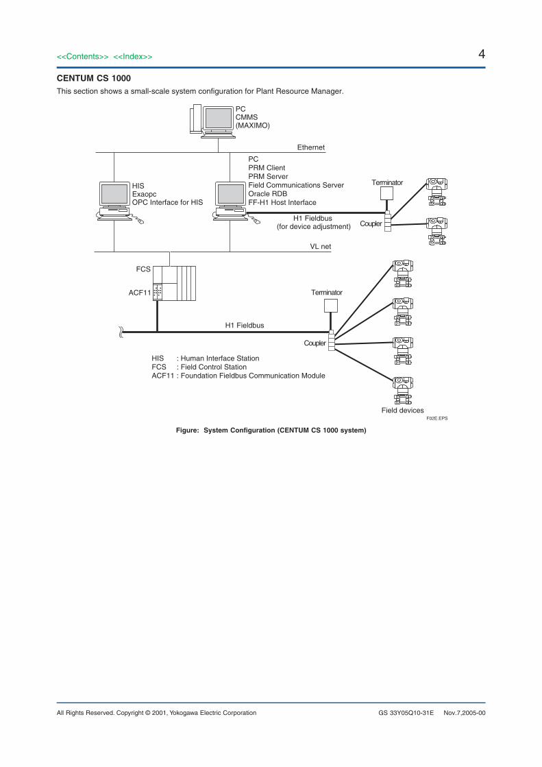
CENTUM CS 1000This section shows a small-scale system configuration for Plant Resource Manager.
VL net
HISFCSACF11
H1 Fieldbus
: Human Interface Station: Field Control Station: Foundation Fieldbus Communication Module
Terminator
Coupler
Field devices
Ethernet
F02E.EPS
PCPRM ClientPRM ServerField Communications ServerOracle RDBFF-H1 Host Interface
ACF11
FCS
PCCMMS(MAXIMO)
HISExaopcOPC Interface for HIS
H1 Fieldbus (for device adjustment)
Terminator
Coupler
Figure: System Configuration (CENTUM CS 1000 system)
Nov.7,2005-00
5<<Contents>> <<Index>>
All Rights Reserved. Copyright © 2001, Yokogawa Electric Corporation GS 33Y05Q10-31E
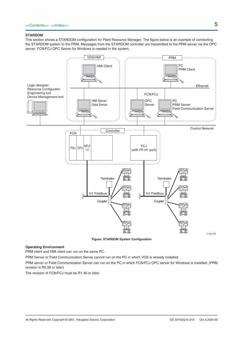
STARDOMThis section shows a STARDOM configuration for Plant Resource Manager. The figure below is an example of connectingthe STARDOM system to the PRM. Messages from the STARDOM controller are transmitted to the PRM server via the OPCserver. FCN/FCJ OPC Server for Windows is needed in the system.
HMI Client
FCN/FCJ
HMI ServerData Server
OPC Server
Control Network
Ethernet
FCN
PCPRM Client
PCPRM ServerField Communication Server
Logic designer Resource ConfiguratorEnginnering toolDevice Management tool
Controller
VDS/HMI PRM
CPUNFLF111
PSUFCJ
(with FF-H1 port)
F10E.EPS
H1 Fieldbus
Terminator
Coupler
H1 Fieldbus
Terminator
Coupler
Figure: STARDOM System Configuration
Operating EnvironmentPRM client and HMI client can run on the same PC.
PRM Server or Field Communication Server cannot run on the PC in which VDS is already installed.
PRM server or Field Communication Server can run on the PC in which FCN/FCJ OPC server for Windows is installed. (PRMrevision is R2.06 or later)
The revision of FCN/FCJ must be R1.40 or later.
Oct.4,2004-00
6
All Rights Reserved. Copyright © 2001, Yokogawa Electric Corporation
<<Contents>> <<Index>>
GS 33Y05Q10-31E Nov.7,2005-00
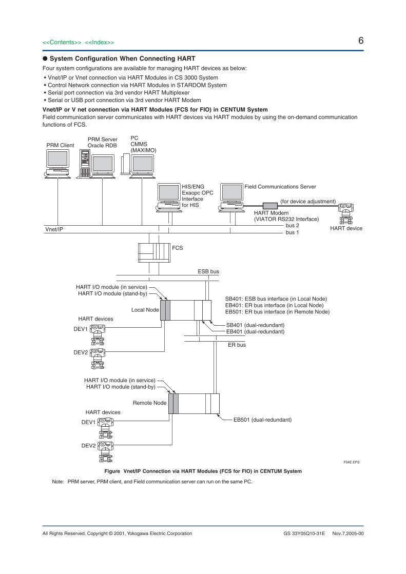
● System Configuration When Connecting HARTFour system configurations are available for managing HART devices as below:
• Vnet/IP or Vnet connection via HART Modules in CS 3000 System• Control Network connection via HART Modules in STARDOM System• Serial port connection via 3rd vendor HART Multiplexer• Serial or USB port connection via 3rd vendor HART Modem
Vnet/IP or V net connection via HART Modules (FCS for FIO) in CENTUM SystemField communication server communicates with HART devices via HART modules by using the on-demand communicationfunctions of FCS.
HIS/ENGExaopc OPC Interface for HIS
Field Communications Server
PRM ClientPRM ServerOracle RDB
Vnet/IPbus 2bus 1
HART device
F04E.EPS
SB401 (dual-redundant)EB401 (dual-redundant)
HART I/O module (in service)HART I/O module (stand-by)
HART I/O module (in service)HART I/O module (stand-by)
EB501 (dual-redundant)
DEV1
DEV2
HART devices
HART devices
Local Node
Remote Node
ESB bus
ER bus
SB401: ESB bus interface (in Local Node)EB401: ER bus interface (in Local Node)EB501: ER bus interface (in Remote Node)
PCCMMS(MAXIMO)
DEV1
DEV2
HART Modem (VIATOR RS232 Interface)
(for device adjustment)
FCS
Figure Vnet/IP Connection via HART Modules (FCS for FIO) in CENTUM System
Note: PRM server, PRM client, and Field communication server can run on the same PC.
7<<Contents>> <<Index>>
All Rights Reserved. Copyright © 2001, Yokogawa Electric Corporation GS 33Y05Q10-31E May 1,2005-00
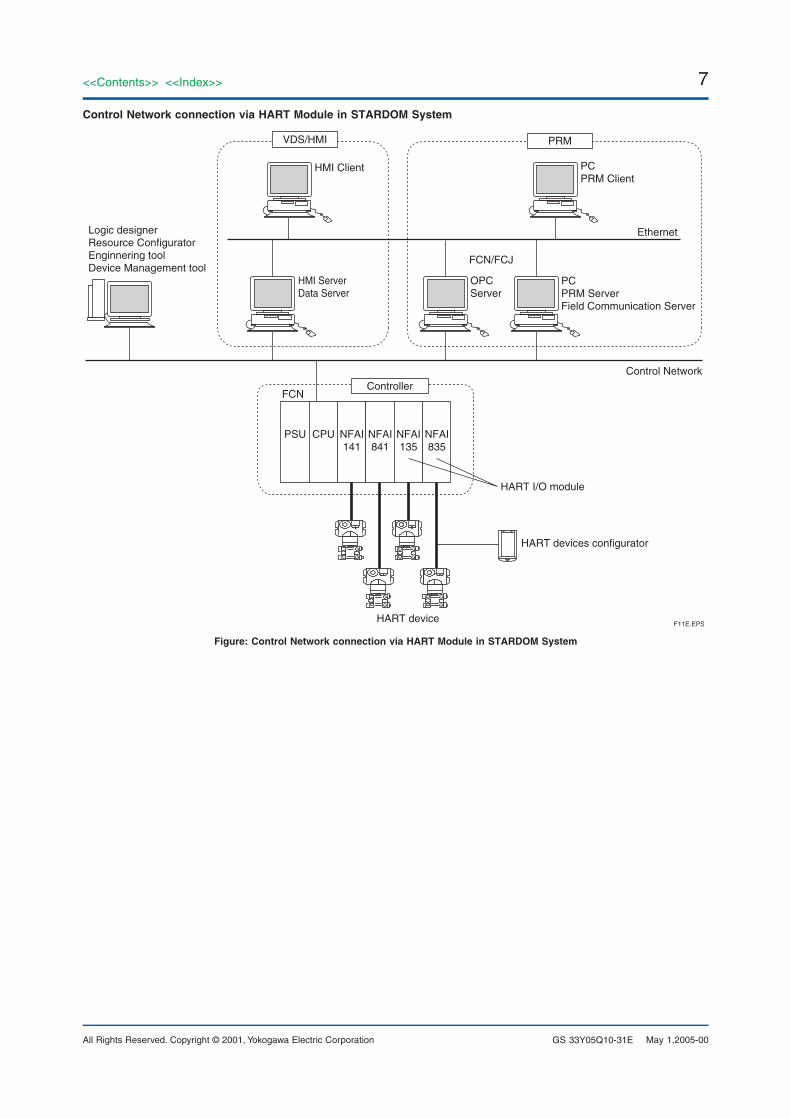
Control Network connection via HART Module in STARDOM System
HMI Client
FCN/FCJ
HMI ServerData Server
HART I/O module
HART devices configurator
HART device
OPC Server
Control Network
Ethernet
FCN
PCPRM Client
PCPRM ServerField Communication Server
Logic designer Resource ConfiguratorEnginnering toolDevice Management tool
Controller
VDS/HMI PRM
PSU NFAI141
CPU NFAI841
NFAI835
NFAI135
F11E.EPS
Figure: Control Network connection via HART Module in STARDOM System
8
All Rights Reserved. Copyright © 2001, Yokogawa Electric Corporation
<<Contents>> <<Index>>
GS 33Y05Q10-31E May 1,2005-00
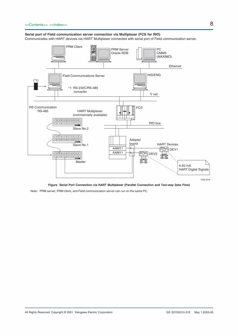
Serial port of Field communication server connection via Multiplexer (FCS for RIO)Communicates with HART devices via HART Multiplexer connected with serial port of Field communication server.
Ethernet
Field Communications Server
PRM ClientPRM ServerOracle RDB
V net
RIO bus
F05E.EPS
FCS
AAM11AAM11
HIS/ENG
HART Multiplexer(commercially available)
Slave No.2
Slave No.1
Master
RS CommunicationRS-485
(*1)
*1: RS-232C/RS-485converter
DEV1
4-20 mA HART Digital Signals
HART DevicesAdopter board
PCCMMS(MAXIMO)
DEV2
Figure Serial Port Connection via HART Multiplexer (Parallel Connection and Two-way Data Flow)
Note: PRM server, PRM client, and Field communication server can run on the same PC.
9<<Contents>> <<Index>>
All Rights Reserved. Copyright © 2001, Yokogawa Electric Corporation GS 33Y05Q10-31E
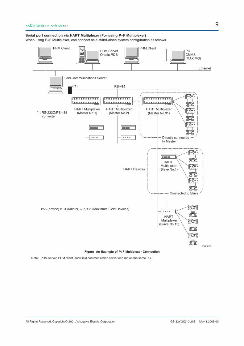
Serial port connection via HART Multiplexer (For using P+F Multiplexer)When using P+F Multiplexer, can connect as a stand-alone system configuration as follows.
Ethernet
Field Communications Server
PRM Client PRM Client
RS-485(*1)
*1: RS-232C/RS-485converter
HART Multiplexer(Master No.1)
HART Multiplexer(Master No.2)
HART Multiplexer(Master No.31)
HART Multiplexer
(Slave No.1)
HART Multiplexer
(Slave No.15)
F06E.EPS
Directly connectedto Master
HART Devices
Connected to Slave
PRM ServerOracle RDB
PCCMMS(MAXIMO)
255 (device) x 31 (Master) = 7,905 (Maximum Field Devices)
Figure An Example of P+F Multiplexer Connection
Note: PRM server, PRM client, and Field communication server can run on the same PC.
May 1,2005-00
10
All Rights Reserved. Copyright © 2001, Yokogawa Electric Corporation
<<Contents>> <<Index>>
GS 33Y05Q10-31E May 1,2005-00
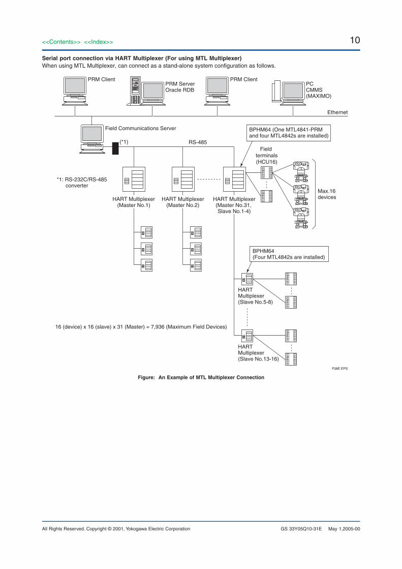
Serial port connection via HART Multiplexer (For using MTL Multiplexer)When using MTL Multiplexer, can connect as a stand-alone system configuration as follows.
Ethernet
Field Communications Server
PRM Client PRM Client
BPHM64 (One MTL4841-PRM and four MTL4842s are installed)
RS-485Field
terminals(HCU16)
(*1)
*1: RS-232C/RS-485converter
F08E.EPS
PRM ServerOracle RDB
PCCMMS(MAXIMO)
HART Multiplexer(Master No.1)
HART Multiplexer(Master No.2)
HART Multiplexer(Master No.31, Slave No.1-4)
HART Multiplexer(Slave No.5-8)
Max.16devices
HART Multiplexer(Slave No.13-16)
BPHM64 (Four MTL4842s are installed)
16 (device) x 16 (slave) x 31 (Master) = 7,936 (Maximum Field Devices)
Figure: An Example of MTL Multiplexer Connection
11<<Contents>> <<Index>>
All Rights Reserved. Copyright © 2001, Yokogawa Electric Corporation GS 33Y05Q10-31E May 1,2005-00
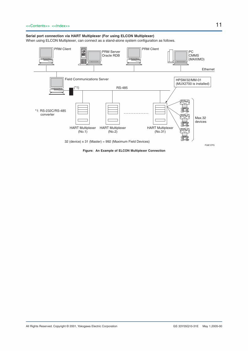
Serial port connection via HART Multiplexer (For using ELCON Multiplexer)When using ELCON Multiplexer, can connect as a stand-alone system configuration as follows.
Ethernet
Field Communications Server
PRM Client PRM Client
HPSM/32/MM-01 (MUX2700 is installed)
RS-485(*1)
*1: RS-232C/RS-485converter
F09E.EPS
PRM ServerOracle RDB
PCCMMS(MAXIMO)
HART Multiplexer(No.1)
HART Multiplexer(No.2)
HART Multiplexer(No.31)
Max.32devices
32 (device) x 31 (Master) = 992 (Maximum Field Devices)
Figure: An Example of ELCON Multiplexer Connection
12
All Rights Reserved. Copyright © 2001, Yokogawa Electric Corporation
<<Contents>> <<Index>>
GS 33Y05Q10-31E
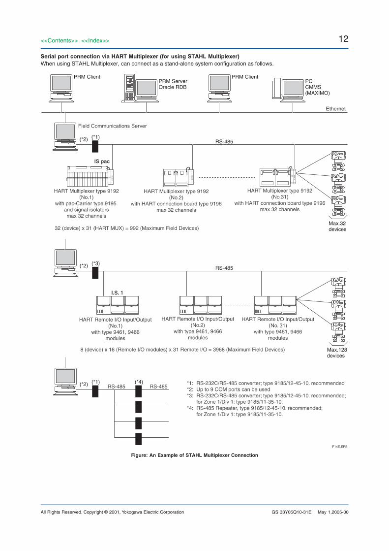
Serial port connection via HART Multiplexer (for using STAHL Multiplexer)When using STAHL Multiplexer, can connect as a stand-alone system configuration as follows.
Ethernet
PRM Client
Field Communications Server
PRM Client
F14E.EPS
PRM ServerOracle RDB
PCCMMS(MAXIMO)
Max.32devices
*1: RS-232C/RS-485 converter; type 9185/12-45-10. recommended*2: Up to 9 COM ports can be used*3: RS-232C/RS-485 converter; type 9185/12-45-10. recommended; for Zone 1/Div 1: type 9185/11-35-10.*4: RS-485 Repeater, type 9185/12-45-10. recommended; for Zone 1/Div 1: type 9185/11-35-10.
HART Multiplexer type 9192(No.1)
with pac-Carrier type 9195 and signal isolatorsmax 32 channels
32 (device) x 31 (HART MUX) = 992 (Maximum Field Devices)
RS-485 RS-485
HART Remote I/O Input/Output(No.2)
with type 9461, 9466modules
HART Remote I/O Input/Output(No. 31)
with type 9461, 9466modules
HART Multiplexer type 9192(No.31)
with HART connection board type 9196max 32 channels
IS pac
RS-485
RS-485
(*1)(*2)
(*3)(*2)
(*1)(*2) (*4)
HART Multiplexer type 9192(No.2)
with HART connection board type 9196max 32 channels
Max.128devices
HART Remote I/O Input/Output(No.1)
with type 9461, 9466modules
8 (device) x 16 (Remote I/O modules) x 31 Remote I/O = 3968 (Maximum Field Devices)
I.S. 1
Figure: An Example of STAHL Multiplexer Connection
May 1,2005-00
13<<Contents>> <<Index>>
All Rights Reserved. Copyright © 2001, Yokogawa Electric Corporation GS 33Y05Q10-31E May 1,2005-00
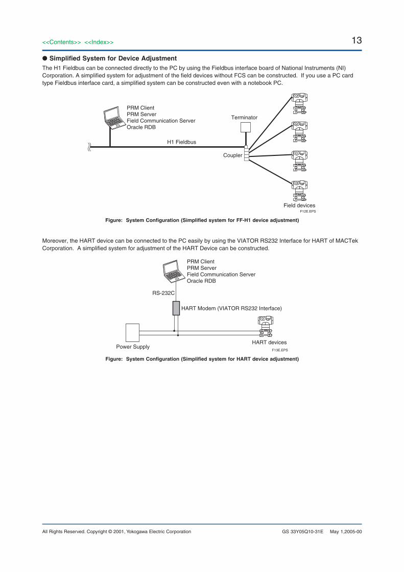
● Simplified System for Device AdjustmentThe H1 Fieldbus can be connected directly to the PC by using the Fieldbus interface board of National Instruments (NI)Corporation. A simplified system for adjustment of the field devices without FCS can be constructed. If you use a PC cardtype Fieldbus interface card, a simplified system can be constructed even with a notebook PC.
H1 Fieldbus
PRM Client PRM ServerField Communication ServerOracle RDB
Terminator
Coupler
Field devicesF12E.EPS
Figure: System Configuration (Simplified system for FF-H1 device adjustment)
Moreover, the HART device can be connected to the PC easily by using the VIATOR RS232 Interface for HART of MACTekCorporation. A simplified system for adjustment of the HART Device can be constructed.
PRM Client PRM ServerField Communication ServerOracle RDB
HART Modem (VIATOR RS232 Interface)
Power SupplyHART devices
RS-232C
F13E.EPS
Figure: System Configuration (Simplified system for HART device adjustment)
14
All Rights Reserved. Copyright © 2001, Yokogawa Electric Corporation
<<Contents>> <<Index>>
GS 33Y05Q10-31E
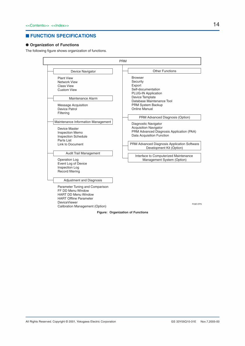
■ FUNCTION SPECIFICATIONS
● Organization of FunctionsThe following figure shows organization of functions.
Device Navigator
PRM
Maintenance Information Management
Audit Trail Management
Adjustment and Diagnosis
Other Functions
Plant ViewNetwork ViewClass ViewCustom View
Device MasterInspection MemoInspection ScheduleParts ListLink to Document
Parameter Tuning and ComparisonFF DD Menu WindowHART DD Menu WindowHART Offline ParameterDeviceViewerCalibration Management (Option)
Operation LogEvent Log of DeviceInspection LogRecord filtering
PRM Advanced Diagnosis (Option)
Interface to Computerized Maintenance Management System (Option)
BrowserSecurityExportSelf-documentationPLUG-IN ApplicationDevice TemplateDatabase Maintenance ToolPRM System BackupOnline Manual
Diagnostic NavigatorAcquisition NavigatorPRM Advanced Diagnosis Application (PAA)Data Acquisition Function
Maintenance Alarm
Message AcquisitionDevice PatrolFiltering
PRM Advanced Diagnosis Application SoftwareDevelopment Kit (Option)
F03E.EPS
Figure: Organization of Functions
Nov.7,2005-00

15<<Contents>> <<Index>>
All Rights Reserved. Copyright © 2001, Yokogawa Electric Corporation GS 33Y05Q10-31E
● Device NavigatorThe Device Navigator provides Plant View, Network View,Class View and Custom View.
Each view displays arrangement of devices, in hierarchicalExplorer-like format. You can select devices and performfunctions in these views. These views can display thedevice status icon using a maintenance alarm function,thus allowing visual identification of device statuses. For adevice with an unconfirmed maintenance alarm, anunconfirmed alarm icon is also displayed.
User access to the hierarchy of the device navigator canbe restricted, which will prevent the person who is not incharge of the device from operating the device by mistake.
Plant ViewDisplays the equipment which makes up the plant, andshows its place in the plant hierarchy, in hierarchicalExplorer-like format. You can manage plant organizationintuitively, based on P & ID diagrams. Unused devices inthe plant can be managed by putting them in the “Spare”Folder, and devices which have failed or are undermaintenance can be placed in the “Off-Service” (Out ofService) Folder. In addition, device statuses usingmaintenance functions can be displayed.
Network ViewDisplays position of device, related to field networkphysical configuration, in an Explorer-like hierarchicalview. The mark next to the device icon shows thecommunication status and alarm status of the device – thecolor of the mark changes if the device fails, so users havean immediate visual view of operating status. Devicestatuses and device communication statuses using themaintenance functions can also be displayed.
Class ViewDisplays devices in an Explorer-like hierarchical view –grouped by supplier, model, and revision. For deviceswhich have failed or are under maintenance, you cancheck the (e.g. spares) status of devices of the same typeat a glance. Device templates can be created with thisClass View.
Custom ViewDisplays devices in the hierarchy structure freely createdby users, in an Explorer-like hierarchical view.
Devices can be classified according to persons in charge,inspection and replacement schedule, operating state, andfailure state.
Nov.7,2005-00
● Maintenance Alarm FunctionThis function provides a message system for strengthen-ing maintenance information and advice guidance. Thefunction transmits information necessary for maintainingdevices to maintenance personnel to help them in the workto be done. The function can not only transmit deviceevent messages but also add necessary information, suchas phenomena, causes, measures, etc., to these mes-sages.
The following functions are provided to strengthen themaintenance information.
Message Acquisition Acquires field device events (for FOUNDATION fieldbus,FF) or events acquired by the CENTUM/STARDOMsystem. User-defined information (message priority level,object information, phenomena, causes, measures, etc.) isautomatically added to raw event information for normal-ized alarms in PRM. Normalized alarms are sent to analarm filtering function.
Device PatrolAcquires self-diagnosis parameter data from field deviceswith diagnosis information and adds used-definedinformation (message priority level, object information,phenomena, causes, and measures) to acquired data toprovide alarms normalized in PRM. These normalizedalarms are then transmitted to an alarm filtering function.Data are acquired periodically or on demand. Necessaryinformation can also be obtained from devices from whichno events are issued.
Filtering FunctionNormalized alarms issued through such functions as themessage acquisition, device patrol or advanced diagnosticapplication, and from messages generated by key entriescan be filtered to prevent the notification of alarm eventmessages that are not in agreement with the specifiedconditions. It is also possible to change notificationmessages on a user-by-user basis.
● Maintenance Information ManagementManages the maintenance information of all devices.
Device MasterManages an inventory of all devices. You can display alist of all devices, or detailed information on a singledevice. For devices with communications functions, thedevice master basic information is automatically createdthrough device recognition and registration (Plug andPlay). No user entries are required.
Inspection MemoMaintains historical records of device inspection memo,and malfunctions. Moreover, maintenance personnel cansave notes about how a failure was handled, as well aswarnings or reminders about maintenance check items, inthe historical record. This can apply to online remoteinspection patrol reports or field inspection patrol reportsbased on a PRM user.
16
All Rights Reserved. Copyright © 2001, Yokogawa Electric Corporation
<<Contents>> <<Index>>
GS 33Y05Q10-31E Nov.7,2005-00
Inspection ScheduleManages inspection schedules (checking, tuning, calibra-tion, etc.) for each device.
Parts ListA device may consist of several parts; the parts listdisplays attributes of each part, and stock information.Enhances efficiency of repair and parts replacement work.For Yokogawa field devices (FF-H1 and HART devices),specific templates are provided.
Link to DocumentThis can display information such as configuration (e.g. P& ID and control drawings), exploded views, onlinemanuals, and graphics, as desired. You can access anddisplay this device-related information using the tag nameas a key. You can also use a URL to access a documentserver connected via Ethernet.
● Audit Trail ManagementThis manages and displays the entire operating historyand historical inspection data carried out on a PRM client,and device alarm events from devices using maintenancealarm functions as historical messages. A list of thesehistorical messages can be displayed in chronologicalorder or on a device priority level and on a messagepriority level. In addition, device IDs and tag names allowthe filtering of these messages; therefore, a specificdevice’s operating history can be easily retrieved.
● Adjustment and Diagnosis FunctionsSupports device online tuning and diagnostic functions.
Parameter Tuning and ComparisonOnline display and setting of device parameter. Comparesstored device historical records with current device data.Facilitates safe switching of device operating conditions,and resetting to past values, while comparing current andpast values – for safety. Can upload device data at anytime, and store it in the database. A collective uploadfunction that can upload all the connected devices at atime is also supported.
Tool• For FOUNDATION fieldbus
Can switch to DD Menu Window and DeviceViewerWindowDD Menu: Using the Method of DD files provided by a
vendor enables to perform Tuning andDiagnosis. The specifications are depen-dent on field devices.
DeviceViewer: DeviceViewer is a PLUG-IN Applicationthat displays the self-diagnosis result of FF-H1 devices. In many cases upper applica-tion program detects errors in devices byreading multi-parameter, containing the self-diagnosis result, saved in FF-H1 devices. Inthe case of Yokogawa FF devices,DeviceViewer displays not only the self-diagnosis result by reading parameters butalso the data displayed on the FF-H1device’s LCD, such as error messages, inuser-friendly format. This allows operatorsto monitor the connected devices from PRMwithout viewing a LCD of field devices.
• For HARTCan switch to DD Menu Window and HART OfflineParameters Window.These windows are equivalent to HART HandheldTerminal.DD Menu: Construe and execute the items of Menu in
HART DD. Refer/set parameters or executeMethod. Record Start/Stop of only thiswindow as operation messages. Theexecuted result of this window is notrecorded in the database or the operationmessage.
HART Offline Parameters: List and display “OfflineParameters” or “Upload Variables” describedin HART DD. Change the parameter values.Record Start/Stop of only this window asoperation messages. Specify a file for eachdevice and save the parameter values; readthe parameter values from the files.
DeviceViewer: The device viewer supports the HARTDevice, either. It displays the self-diagnosishardware status and configuration status ofthe HART Device.
Calibration ManagementThe PRM database manages equipment calibration data.Calibration results are registered in databases, andcalibrated values, errors and pass or fail (judgment) maybe displayed. The calibration management functions canrequire the administrator to acknowledge (approve)calibration results. After such acknowledgement ofcalibration results, only the administrator can change theresults.
The operation history management functions retain arecord of all downloading and uploading of calibrationdata.
If you use the Documenting Calibrator, you can use it todownload or upload calibration data. In addition, calibra-tion results are automatically stored in the database. (*1)
*1: Connection to the Documenting Calibrator is anoptional extra.
17<<Contents>> <<Index>>
All Rights Reserved. Copyright © 2001, Yokogawa Electric Corporation GS 33Y05Q10-31E
● Other Functions
BrowserCan search for devices using device attribute informationsuch as device ID, device tag name, device tag comment,block name, or parameter value.
SecurityDuring maintenance of field devices, restricts operation tospecific user(s) – or restricts range of operations permitted– to prevent system trouble due to operator errors, and tomaintain system security.
The user name and operation record of the logged-inoperator is recorded in the operation history. User Groupcan be used to assign user privileges to groups of users(i.e. restrict rights) according to job function.
Moreover, the Device Security Function allows the devicenavigator to display devices only for the specific group.
ExportCan output a list of all devices (such as device ID, devicetag, and device tag comment) stored in the database to atext file in CSV format. You can use information managedwith PRM on facility management software and the like.
Self-documentationAutomatically creates device documentation for manage-ment. Can collectively print out data stored in thedatabase in report format. Device information is managedelectronically, and can be printed out on demand. Infor-mation on each window can be printed out as individualreports, so a report can be printed out after maintenancework to provide a maintenance work record.The following print properties can be edited:
• Printing range• Table of contents• Header/footer• Cover page
PLUG-IN ApplicationThe software package provided by third-party devicevendors which is built into PRM system. The PLUG-INApplication runs on the client PC, and it accesses to fielddevices and Oracle database in PRM server via PLUG-INApplication Library.
Yokogawa Electric supplies DeviceViewer and the PLUG-IN ValveNavi for Yokogawa Advanced Valve Positioner,YVP110 as a PLUG-IN application. This PLUG-INValveNavi helps users to easily calibration and diagnosethe YVP110.
This PLUG-IN ValveNavi also supports Signature functionfor control valve diagnosis.
The function is based on standalone ValveNavi (YVP20SYVP Management Software).
For its functions, refer to the separate GS 21B04C50-01Efor Model YVP20S YVP Management Software.
Nov.7,2005-00
• Supported PLUG-INDeviceViewer:
FF-H1 devices:DPharp EJA Series: Digital Differential Pressure and
Pressure Transmitter, R2 or laterEJA for Software Download; R1 or laterDPharp EJX Series: Digital Differential Pressure and
Pressure Transmitter, R1 or laterYTA Series: Temperature Transmitter, R2 or laterDY, DYA digital YEWFLO, R1 or laterDY, DYA digital YEWFLO for Software Download, R1
or laterYEWFLO*E: Vortex Flow Meter, R2 or laterADMAG AE Series: Magnetic Flow Meter, R1 or
laterYVP110: Advanced Valve Positioner, R2 or laterYVP110 for Software Download: R1 or laterYPK110: Fieldbus-to-Pneumatic converter, R1 or
laterPH202F: 2-Wire Type pH Meter, R1 or laterSC202F: 2-Wire Type Conductivity Meter, R1 or
laterISC202F: 2-Wire Inductive Conductivity Meter, R1
or laterDAQSTATION DX Series, R3 or laterFVP: Valve Positioner (Dresser), R2 or laterFVP for Software Download: R1 or laterDVC5000f: Digital Valve Controller Fisher, R8 or R9)FF-01: Valve Actuator, R2FP302: Fieldbus to Pressure Convertor (SMAR),
R4 or later5081C/T: Conductivity Transmitter (Rosemount
Analytical), R1 or later5081pH: Conductivity Transmitter (Rosemount
Analytical), R1 or later848T: Eight Input Temperature Transmitter
(Rosemount Inc.), R4644HF: Temperature Transmitter (Rosemount
Inc.), R1 or later752: Remote Indicator (Rosemount Inc.), R13051S: Pressure Transmitter (Rosemount Inc.),
R14 or later3144P: Temperature Transmitter (Rosemount
Inc.), R1 or later8800: Vortex Flowmeter (Rosemount Inc.), R5
or later8742: Mag Flow Meter (Rosemount Inc.), R4 or
laterMVD2700: Mass Flow Sensor (Micro Motion), R3 or
later3244MV: Temperature Transmitter (Rosemount
Inc.), R5 or laterBA488: Fieldbus Display (BEKA), R1 or later
HART devices:DPharp EJA Series: Digital Differential Pressure and
Pressure Transmitter, R1 or laterDPharp EJX Series: Digital Differential pressure and
Pressure Transmitter, R1 or laterDY, DYA digital YEWFLO, R2 or later
PLUG-IN ValveNavi for YVP110 (Rev. 2.1 or later)
18
All Rights Reserved. Copyright © 2001, Yokogawa Electric Corporation
<<Contents>> <<Index>>
GS 33Y05Q10-31E
Device Template FunctionTemplates in which device information is freely defined aresupplied. These templates can simplify device setting inengineering work. In addition, the engineering items whichrequire actual devices can be reduced.
Database Maintenance ToolThe PRM database capacity increases as the number ofdevices increases. If the operation history and parameterhistory are used for an extended period of time, largequantities of historical data are stored. An increase in thedatabase will have a bad effect on the PRM performance.The database maintenance tool optimizes large databasesto enable effective operation of the PRM.
By using this tool, the database maintenance work isexecuted more easily than when using Database Mainte-nance Command of Oracle directly.
Online Manual (R2.02 or later)From R2.02, all instruction manuals are provided in PDFformat on CD-ROM. This enables you to view and print theelectronic instruction manuals on-demand.
PRM System BackupPRM provides a simple tool to back up data to meet userenvironments. This tool can back up registry information,PRM databases, advanced diagnosis databases, etc.
Nov.7,2005-00
19<<Contents>> <<Index>>
All Rights Reserved. Copyright © 2001, Yokogawa Electric Corporation GS 33Y05Q10-31E
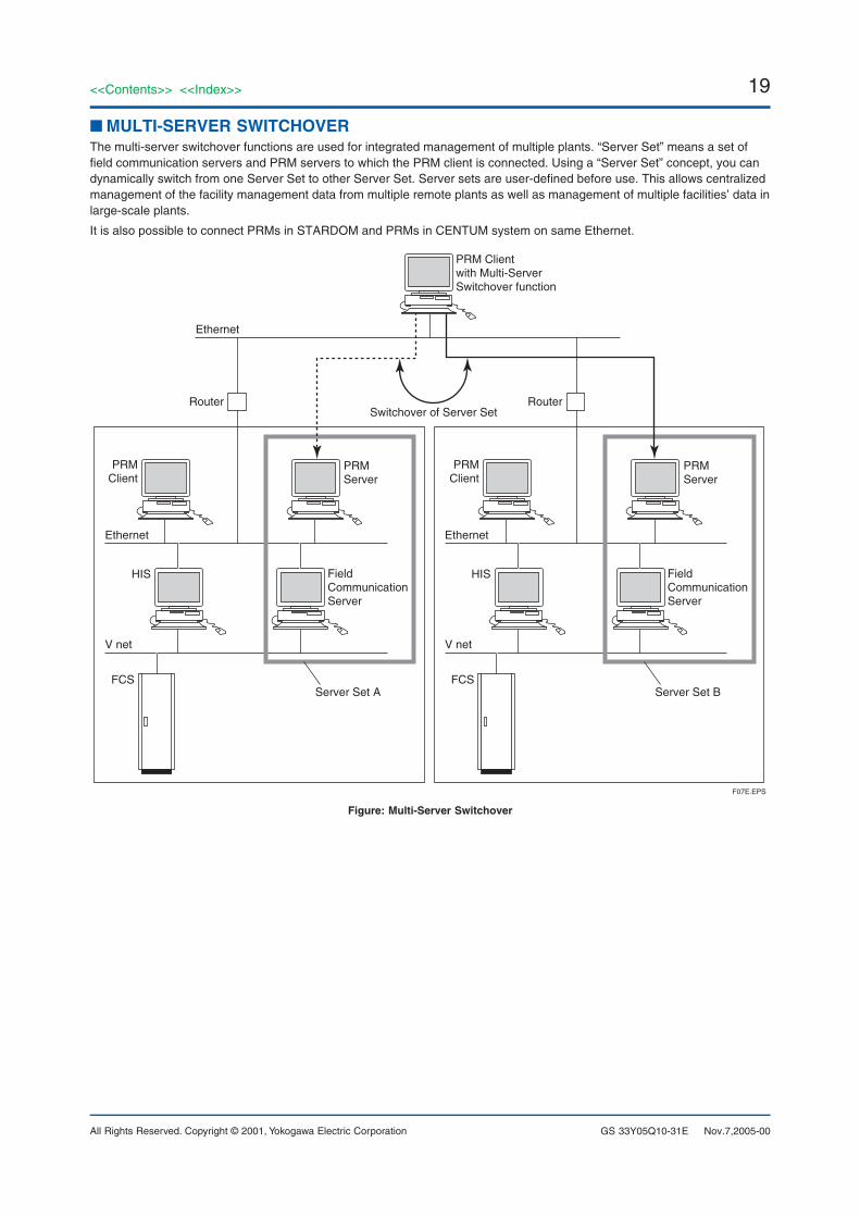
■ MULTI-SERVER SWITCHOVERThe multi-server switchover functions are used for integrated management of multiple plants. “Server Set” means a set offield communication servers and PRM servers to which the PRM client is connected. Using a “Server Set” concept, you candynamically switch from one Server Set to other Server Set. Server sets are user-defined before use. This allows centralizedmanagement of the facility management data from multiple remote plants as well as management of multiple facilities’ data inlarge-scale plants.
It is also possible to connect PRMs in STARDOM and PRMs in CENTUM system on same Ethernet.
Ethernet
Ethernet
Router
V net
Server Set A
PRMClient
PRM Clientwith Multi-ServerSwitchover function
F07E.EPS
PRMServer
Switchover of Server Set
Field Communication Server
HIS
FCS
Ethernet
V net
Server Set B
PRMClient
PRMServer
Field Communication Server
HIS
FCS
Router
Figure: Multi-Server Switchover
Nov.7,2005-00
20
All Rights Reserved. Copyright © 2001, Yokogawa Electric Corporation
<<Contents>> <<Index>>
GS 33Y05Q10-31E
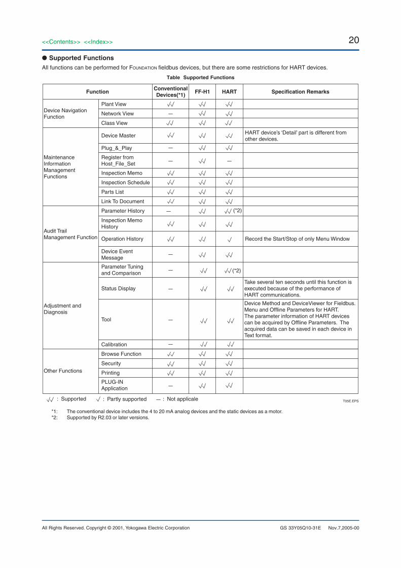
● Supported FunctionsAll functions can be performed for FOUNDATION fieldbus devices, but there are some restrictions for HART devices.
Table Supported Functions
Device NavigationFunction
Audit Trail Management Function
Adjustment and Diagnosis
Other Functions
HART device’s ‘Detail’ part is different from other devices.
Record the Start/Stop of only Menu Window
Take several ten seconds until this function is executed because of the performance of HART communications.
Device Method and DeviceViewer for Fieldbus. Menu and Offline Parameters for HART.The parameter information of HART devices can be acquired by Offline Parameters. The acquired data can be saved in each device in Text format.
Plant View
(*2)
(*2)
Maintenance Information Management Functions
Network View
Class View
Plug_&_Play
Inspection Memo
Parameter Tuning and Comparison
Status Display
Inspection Schedule
Parts List
Browse Function
Security
Printing
PLUG-IN Application
Calibration
Link To Document
Parameter History
Device EventMessage
Operation History
Tool
Inspection MemoHistory
Register from Host_File_Set
Device Master
Specification RemarksFF-H1 HARTConventionalDevices(*1)Function
T05E.EPS: Supported : Partly supported : Not applicale
*1: The conventional device includes the 4 to 20 mA analog devices and the static devices as a motor.*2: Supported by R2.03 or later versions.
Nov.7,2005-00
21<<Contents>> <<Index>>
All Rights Reserved. Copyright © 2001, Yokogawa Electric Corporation GS 33Y05Q10-31E Nov.7,2005-00
■ OPERATING ENVIRONMENT
● Hardware RequirementsThe necessary amounts of main memory and disk spacedepend on the number of devices connected. This sectiondiscusses the minimum hardware requirements when nomore than 1,000 devices are connected. If more than1,000 devices need to be connected, consult Yokogawa.
PRM ServerIBM PC/AT-compatible: Pentium 300 MHz or higher,
Pentium III 1 GHz or higher recommendedMain memory: 256 MB or greater, 512 MB or greater
recommended.1 GB or greater when using Oracle 10g
Disk capacity: 12 GB or greater total disk space(at least 5 GB must be free.)
Other requirements:DAT drive (for backup).Ethernet card
Display: 256 colors or more are mandatory
PRM ClientIBM PC/AT-compatible: Pentium 300 MHz or higher,
Pentium III 1 GHz higher recommendedMain memory: 64 MB or greater, 128 MB or greater
recommended.Disk capacity: 8 GB or greater total disk space
(at least 200 MB must be free.)Other requirement: Ethernet cardDisplay: 1024 x 768 (256 calor) or more are manda-
tory
Field Communications ServerIBM PC/AT-compatible: Pentium 300 MHz or higher,
Pentium III 1 GHz higher recommendedMain memory: The necessary amount of main memory
is shown below.
Recommended Memory SizeNumber of FCSes
1 to 16
17 to 48
100 + 80 x (number of FCSes)
1380 + 10 x (number of FCSes–16)T18E.EPS
Disk capacity: 4 GB or greater total disk space(at least 200 MB must be free.)
Other requirements: VF701 (Vnet) or VI701 (Vnet/IP)card, Ethernet card
When connecting FF-H1 Fieldbus directly:The following cards of National InstrumentsCorporation are used.AT-FBUS ISA bus connectionPCMCIA-FBUS PCMCIA CardNI PCI-FBUS/2 PCI bus connection
When using P+F Multiplexer:Multiplexer (Master): KFD2-HMM-16 (P+F) (*1)Multiplexer (Slave): KFD0-HMS-16 (P+F)Cable (connecting Master or Slave to terminal block):
K-HM 26 (P+F)Cable (connecting Master to Slave): K-HM 14 (P+F)Terminal Block: FI-**-PFH-Y... (** is specified
depending on user’s need) (P+F)Power Supply: KFD2-EB2 (P+F)Power Rail (an equipment to be used for fixing
Multiplexer to a terminal board)Recommended RS-232C/RS-485 Converter:
IC108A (BLACK BOX)MA-45 (Westermo)
Cable (connecting Master to converter):Twisted pair cable (category 5)
Cable (connecting converter to PC):EVNBMC (BLACK BOX)DB25 male – DB9 female (inch screwthread), Straght connection
*1: Number of Multiplexer (Master): Max.31Number of connectable devices: Max.255 per oneMaster
When using MTL Multiplexer:Multiplexer (Master): MTL4841-PRM (MTL)
MTL4841 (standard type) and MTL4841-AMS cannot connect to PRM.
Multiplexer (Slave): MTL4842 (MTL)Back plane: BPHM64 (MTL)HART connection Unit (16ch HART Inputs/Outputs ):
HCU16 (MTL)Recommended RS-232C/RS-485 Converter:
IC108A (BLACK BOX)MA-45 (Westermo)
Cable for connection between Master and Slave (4or less):Not required (connectable on BPHM64)
Cable for connection between Master and Slave (5or more):
Connector type:10 way DIN41651 bump polarizedCable: 0.05 inch pitch standard ribbonMaximum length: 4m
Cable for connection between Master and Master:Not specially specified (normal RS-485cable is used)
Cable for connection between BPHM64 and HCU16:Connector type: 20 way DIN41651 bump polarizedCable: 0.05 inch pitch standard ribbonMaximum length: 15m
When using P+F ELCON Multiplexer:Multiplexer (Master and Slave):
MUX2700 (P+F ELCON)Board for connection: HPSM/32/MM-01 (P+F
ELCON)Recommended RS-232C/RS-485 Converter:
IC108A (BLACK BOX)MA-45 (Westermo)
Cable: Only normal RS485 cable is required
22
All Rights Reserved. Copyright © 2001, Yokogawa Electric Corporation
<<Contents>> <<Index>>
GS 33Y05Q10-31E
When using R. STAHL HART Multiplexer IS pac:Multiplexer: 9192/32-10-10IS pac Carrier: 9195/08H-***-*** or 9195/16H-***-***
or HART Connection Board: 9196/**H-XX0-***
Cable (connecting multiplexer to IS pac carrier orconnection board): with carrier or boardincluded
Cable (connecting HART Multiplexer to converter):shielded twisted pair; plug = Sub-D 9,female; max length = 1200 m
Recommended RS-232C / RS-485 converter, suitablefor zone 2 / div 2 installation: 9185/12-45-10*
Cable (connecting converter to PC): Type F interfacecable; max length = 15 m
When using R. STAHL Remote I/O I.S. 1 withServiceBus:
Analog Input or Analog Output Modules HART: 9461/12-08-** or 9466/12-08-11; CPU & PowerModule 9440/**
Cable (connecting CPU and power module to con-verter): shielded twisted pair; plug = Sub-D 9, female; max length = 1200 m
Recommended RS-232C / RS-485 converter: 9185/12-45-10*
RS-232C / RS-485-IS converter for remote I/O zone 1 /div 1 installation: 9185/11-35-10*
Cable (connecting converter to PC): Type F interfacecable; max length = 15 m
When using simplified system for HART:The following hardware is used VIATORRS232 HART Interface Model 010001(MACTek)
Nov.7,2005-00
When installing PRM Server, Field CommunicationServer, and PRM Client in one PC:
IBM PC/AT-compatible: Pentium 300 MHz or higher(Pentium III 1 GHz or higher recommended)
Main memory: 1 GB (*1) or greater, 2 GB or greaterrecommended
*1: 2 GB minimum, if an advanced diagnostic applica-tion coexists.
Disk capacity: 12 GB or greater total disk space (atleast 5 GB must be free)
Other requirements: VF701 (Vnet) or VI701 (Vnet/IP)card, Ethernet card
OPC Server (for STARDOM system)IBM PC/AT-compatible: Pentium 300 MHz or 400 MHz
or faster recommendedMain memory: 256 MB or 512 MB or greater recom-
mendedDisk capacity: There must be at least 1 GB of free
space.Ethernet card: 100BASE-TX, 10BASE-T, 10BASE-5
Two communications devices are needed to separate theSTARDOM information network from its control network.
23<<Contents>> <<Index>>
All Rights Reserved. Copyright © 2001, Yokogawa Electric Corporation GS 33Y05Q10-31E
● Software Requirements
PRM ServerOS:
Windows Server 2003 Service Pack 1Windows XP Service Pack 1 or 2Windows 2000 (Server/Professional) Service Pack 4
Internet Explorer 5.0 or later versionOracle 8i: Oracle Database R8.1.6, R8.1.7Oracle 9i: Oracle Database R9.2.0Oracle 10g:Oracle Database R10.1.0
Note: Oracle 8i cannot run on Windows XP and Windows Server 2003.
PRM ClientOS:
Windows Server 2003 Service Pack 1Windows XP Service Pack 1 or 2Windows 2000 (Server/Professional) Service Pack 4
Oracle Client 8.1.6/8.1.7 Net8iOracle Client 9.2.0Oracle 10g:Oracle Database R10.1.0
Note: Oracle 8i cannot run on Windows XP and Windows Server 2003.Software for document: Adobe Reader 6.0, Adobe Reader 7.0.0
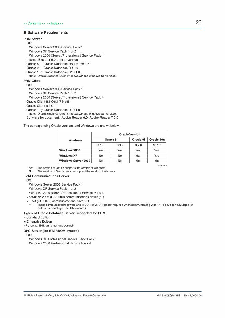
The corresponding Oracle versions and Windows are shown below.
Oracle Version
Windows
Windows 2000
Windows Server 2003
Windows XP
T14E.EPS
Oracle 8i
8.1.6
Yes
No
No
8.1.7
Yes
No
No
Oracle 9i
9.2.0
Yes
Yes
Yes
Oracle 10g
10.1.0
Yes
Yes
Yes
Yes: The version of Oracle supports the version of Windows.No: The version of Oracle does not support the version of Windows.
Field Communications ServerOS:
Windows Server 2003 Service Pack 1Windows XP Service Pack 1 or 2Windows 2000 (Server/Professional) Service Pack 4
Vnet/IP or V net (CS 3000) communications driver (*1)VL net (CS 1000) communications driver (*1)
*1: These communications drivers and VF701 (or VI701) are not required when communicating with HART devices via Multiplexer.(without connecting CENTUM system.)
Types of Oracle Database Server Supported for PRM• Standard Edition• Enterprise Edition(Personal Edition is not supported)
OPC Server (for STARDOM system)OS:
Windows XP Professional Service Pack 1 or 2Windows 2000 Professional Service Pack 4
Nov.7,2005-00
24
All Rights Reserved. Copyright © 2001, Yokogawa Electric Corporation
<<Contents>> <<Index>>
GS 33Y05Q10-31E Nov.7,2005-00
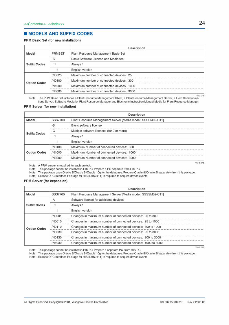
■ MODELS AND SUFFIX CODESPRM Basic Set (for new installation)
Description
Model PRMSET Plant Resource Management Basic Set
Suffix Codes
-S Basic Software License and Media fee
1 Always 1
1 English version
Option Codes
/N0025 Maximum number of connected devices: 25
/N0100 Maximum number of connected devices: 300
/N1000 Maximum number of connected devices: 1000
T06E.EPS
/N3000 Maximum number of connected devices: 3000
Note: The PRM Basic Set includes a Plant Resource Management Client, a Plant Resource Management Server, a Field Communica-tions Server, Software Media for Plant Resource Manager and Electronic Instruction Manual Media for Plant Resource Manager.
PRM Server (for new installation)
Description
Model SSS7700 Plant Resource Management Server [Media model: SSSSM02-C11]
Suffix Codes
-S Basic software license
-C Multiple software licenses (for 2 or more)
1 Always 1
1 English version
Option Codes
/N0100 Maximum Number of connected devices: 300
/N1000 Maximum Number of connected devices: 1000
/N3000 Maximum Number of connected devices: 3000
T01E.EPSNote: A PRM server is required for each project.Note: This package cannot be installed in HIS PC. Prepare a PC separate from HIS PC.Note: This package uses Oracle 8i/Oracle 9i/Oracle 10g for the database. Prepare Oracle 8i/Oracle 9i separately from this package.Note: Exaopc OPC Interface Package for HIS (LHS2411) is required to acquire device events.
PRM Server (for expansion)
Description
Model SSS7700 Plant Resource Management Server [Media model: SSSSM02-C11]
Suffix Codes
-A Software license for additional devices
1 Always 1
1 English version
Option Codes
/N0001 Changes in maximum number of connected devices: 25 to 300
/N0010 Changes in maximum number of connected devices: 25 to 1000
/N0110 Changes in maximum number of connected devices: 300 to 1000
T02E.EPS
/N0030 Changes in maximum number of connected devices: 25 to 3000
/N0130 Changes in maximum number of connected devices: 300 to 3000
/N1030 Changes in maximum number of connected devices: 1000 to 3000
Note: This package cannot be installed in HIS PC. Prepare a separate PC from HIS PC.Note: This package uses Oracle 8i/Oracle 9i/Oracle 10g for the database. Prepare Oracle 8i/Oracle 9i separately from this package.Note: Exaopc OPC Interface Package for HIS (LHS2411) is required to acquire device events.
25<<Contents>> <<Index>>
All Rights Reserved. Copyright © 2001, Yokogawa Electric Corporation GS 33Y05Q10-31E
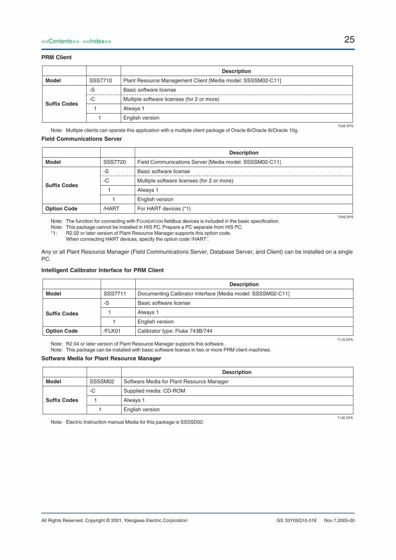
PRM Client
Description
Model SSS7710 Plant Resource Management Client [Media model: SSSSM02-C11]
Suffix Codes
-S Basic software license
-C Multiple software licenses (for 2 or more)
1 Always 1
1 English versionT03E.EPS
Note: Multiple clients can operate this application with a multiple client package of Oracle 8i/Oracle 9i/Oracle 10g.
Field Communications Server
Description
Model SSS7720 Field Communications Server [Media model: SSSSM02-C11]
Suffix Codes
-S Basic software license
-C Multiple software licenses (for 2 or more)
1 Always 1
1 English version
T04E.EPS
Option Code /HART For HART devices (*1)
Note: The function for connecting with FOUNDATION fieldbus devices is included in the basic specification.Note: This package cannot be installed in HIS PC. Prepare a PC separate from HIS PC.*1: R2.02 or later version of Plant Resource Manager supports this option code.
When connecting HART devices, specify the option code ‘/HART’.
Any or all Plant Resource Manager (Field Communications Server, Database Server, and Client) can be installed on a singlePC.
Intelligent Calibrator Interface for PRM Client
Description
Model SSS7711 Documenting Calibrator Interface [Media model: SSSSM02-C11]
Suffix Codes
-S Basic software license
1 Always 1
1 English version
T11E.EPS
Option Code /FLK01 Calibrator type: Fluke 743B/744
Note: R2.04 or later version of Plant Resource Manager supports this software.Note: This package can be installed with basic software license in two or more PRM client machines.
Software Media for Plant Resource Manager
Description
Model SSSSM02 Software Media for Plant Resource Manager
Suffix Codes
-C Supplied media: CD-ROM
1 Always 1
1 English version
T13E.EPSNote: Electric Instruction manual Media for this package is SSSSD02.
Nov.7,2005-00
26
All Rights Reserved. Copyright © 2001, Yokogawa Electric Corporation
<<Contents>> <<Index>>
GS 33Y05Q10-31E
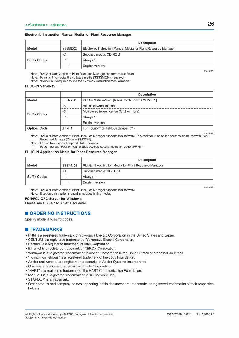
Electronic Instruction Manual Media for Plant Resource Manager
Description
Model SSSSD02 Electronic Instruction Manual Media for Plant Resource Manager
Suffix Codes
-C Supplied media: CD-ROM
1 Always 1
1 English version
T08E.EPSNote: R2.02 or later version of Plant Resource Manager supports this software.Note: To install this media, the software media (SSSSM02) is required.Note: No license is required to use the electronic instruction manual media.
PLUG-IN ValveNavi
Description
Model SSS7750 PLUG-IN ValveNavi [Media model: SSSAM02-C11]
Suffix Codes
Option Code
-C Multiple software license (for 2 or more)
1 Always 1
1 English version
T09E.EPS
-S Basic software license
/FF-H1 For FOUNDATION fieldbus devices (*1)
Note: R2.03 or later version of Plant Resource Manager supports this software. This package runs on the personal computer with PlantResource Manager (Client) (SSS7710).
Note: This software cannot support HART devices.*1: To connect with FOUNDATION fieldbus devices, specify the option code “/FF-H1.”
PLUG-IN Application Media for Plant Resource Manager
Description
Model SSSAM02 PLUG-IN Application Media for Plant Resource Manager
Suffix Codes
-C Supplied media: CD-ROM
1 Always 1
1 English versionT10E.EPS
Note: R2.03 or later version of Plant Resource Manager supports this software.Note: Electronic instruction manual is included in this media.
FCN/FCJ OPC Server for WindowsPlease see GS 34P02Q61-01E for detail.
■ ORDERING INSTRUCTIONSSpecify model and suffix codes.
■ TRADEMARKS• PRM is a registered trademark of Yokogawa Electric Corporation in the United States and Japan.• CENTUM is a registered trademark of Yokogawa Electric Corporation.• Pentium is a registered trademark of Intel Corporation.• Ethernet is a registered trademark of XEROX Corporation.• Windows is a registered trademark of Microsoft Corporation in the United States and/or other countries.• “FOUNDATION fieldbus” is a registered trademark of Fieldbus Foundation.• Adobe and Acrobat are registered trademarks of Adobe Systems Incorporated.• Oracle is a registered trademark of Oracle Corporation.• “HART” is a registered trademark of the HART Communication Foundation.• MAXIMO is a registered trademark of MRO Software, Inc.• STARDOM is a trademark.• Other product and company names appearing in this document are trademarks or registered trademarks of their respective
holders.
Subject to change without notice.Nov.7,2005-00