General Specifications Main unit —stand-alone type ... · General Specifications ... Universal,...
21
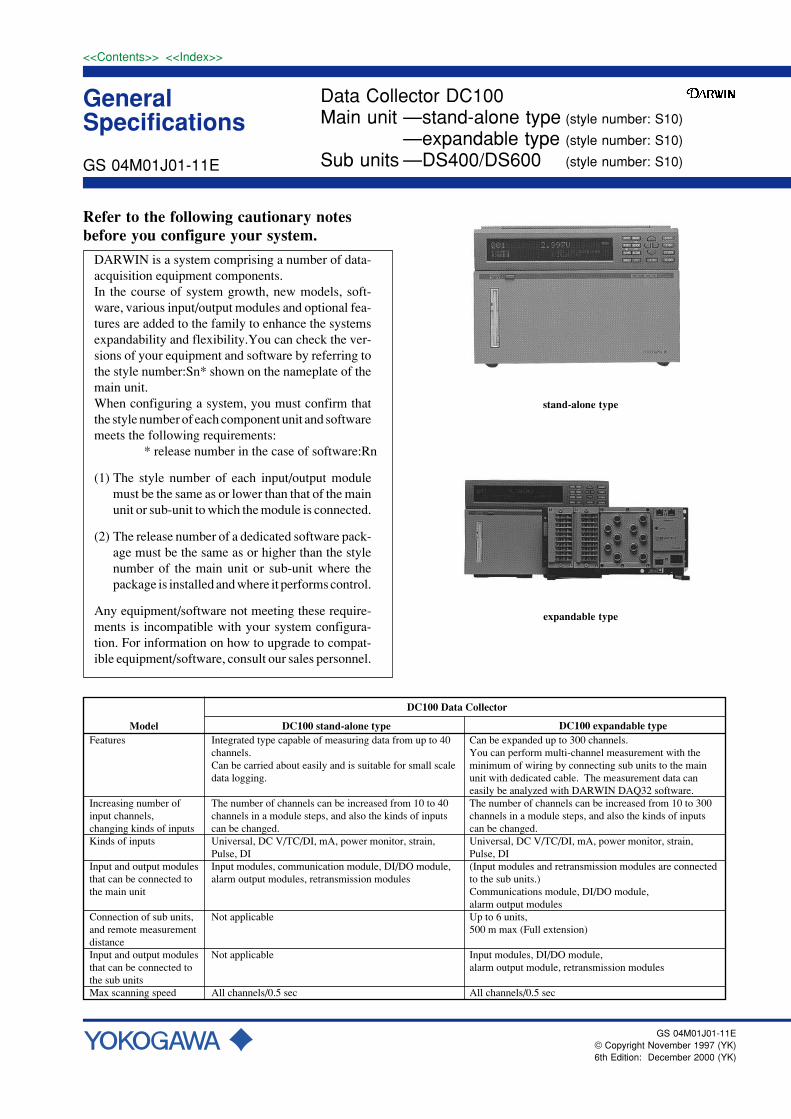
General Specifications <<Contents>> <<Index>> Refer to the following cautionary notes before you configure your system. DARWIN is a system comprising a number of data- acquisition equipment components. In the course of system growth, new models, soft- ware, various input/output modules and optional fea- tures are added to the family to enhance the systems expandability and flexibility.You can check the ver- sions of your equipment and software by referring to the style number:Sn* shown on the nameplate of the main unit. When configuring a system, you must confirm that the style number of each component unit and software meets the following requirements: * release number in the case of software:Rn (1) The style number of each input/output module must be the same as or lower than that of the main unit or sub-unit to which the module is connected. (2) The release number of a dedicated software pack- age must be the same as or higher than the style number of the main unit or sub-unit where the package is installed and where it performs control. Any equipment/software not meeting these require- ments is incompatible with your system configura- tion. For information on how to upgrade to compat- ible equipment/software, consult our sales personnel. Model DC100 Data Collector DC100 stand-alone type Features Increasing number of input channels, changing kinds of inputs Kinds of inputs Input and output modules that can be connected to the main unit Connection of sub units, and remote measurement distance Input and output modules that can be connected to the sub units Max scanning speed Integrated type capable of measuring data from up to 40 channels. Can be carried about easily and is suitable for small scale data logging. The number of channels can be increased from 10 to 40 channels in a module steps, and also the kinds of inputs can be changed. Universal, DC V/TC/DI, mA, power monitor, strain, Pulse, DI Input modules, communication module, DI/DO module, alarm output modules, retransmission modules Not applicable Not applicable All channels/0.5 sec DC100 expandable type Can be expanded up to 300 channels. You can perform multi-channel measurement with the minimum of wiring by connecting sub units to the main unit with dedicated cable. The measurement data can easily be analyzed with DARWIN DAQ32 software. The number of channels can be increased from 10 to 300 channels in a module steps, and also the kinds of inputs can be changed. Universal, DC V/TC/DI, mA, power monitor, strain, Pulse, DI (Input modules and retransmission modules are connected to the sub units.) Communications module, DI/DO module, alarm output modules Up to 6 units, 500 m max (Full extension) Input modules, DI/DO module, alarm output module, retransmission modules All channels/0.5 sec GS 04M01J01-11E © Copyright November 1997 (YK) 6th Edition: December 2000 (YK) Data Collector DC100 Main unit —stand-alone type (style number: S10) —expandable type (style number: S10) Sub units —DS400/DS600 (style number: S10) GS 04M01J01-11E stand-alone type expandable type
Transcript of General Specifications Main unit —stand-alone type ... · General Specifications ... Universal,...
GeneralSpecifications
<<Contents>> <<Index>>
Refer to the following cautionary notesbefore you configure your system.
DARWIN is a system comprising a number of data-acquisition equipment components.In the course of system growth, new models, soft-ware, various input/output modules and optional fea-tures are added to the family to enhance the systemsexpandability and flexibility.You can check the ver-sions of your equipment and software by referring tothe style number:Sn* shown on the nameplate of themain unit.When configuring a system, you must confirm thatthe style number of each component unit and softwaremeets the following requirements:
* release number in the case of software:Rn
(1) The style number of each input/output modulemust be the same as or lower than that of the mainunit or sub-unit to which the module is connected.
(2) The release number of a dedicated software pack-age must be the same as or higher than the stylenumber of the main unit or sub-unit where thepackage is installed and where it performs control.
Any equipment/software not meeting these require-ments is incompatible with your system configura-tion. For information on how to upgrade to compat-ible equipment/software, consult our sales personnel.
Model
DC100 Data Collector
DC100 stand-alone typeFeatures
Increasing number of input channels, changing kinds of inputsKinds of inputs
Input and output modules that can be connected to the main unit
Connection of sub units, and remote measurement distanceInput and output modules that can be connected to the sub unitsMax scanning speed
Integrated type capable of measuring data from up to 40channels. Can be carried about easily and is suitable for small scale data logging.
The number of channels can be increased from 10 to 40 channels in a module steps, and also the kinds of inputs can be changed.Universal, DC V/TC/DI, mA, power monitor, strain, Pulse, DI Input modules, communication module, DI/DO module, alarm output modules, retransmission modules
Not applicable
Not applicable
All channels/0.5 sec
DC100 expandable typeCan be expanded up to 300 channels.You can perform multi-channel measurement with the minimum of wiring by connecting sub units to the main unit with dedicated cable. The measurement data can easily be analyzed with DARWIN DAQ32 software.The number of channels can be increased from 10 to 300 channels in a module steps, and also the kinds of inputs can be changed.Universal, DC V/TC/DI, mA, power monitor, strain, Pulse, DI(Input modules and retransmission modules are connected to the sub units.)Communications module, DI/DO module, alarm output modulesUp to 6 units, 500 m max (Full extension)
Input modules, DI/DO module, alarm output module, retransmission modules All channels/0.5 sec
GS 04M01J01-11E© Copyright November 1997 (YK)6th Edition: December 2000 (YK)
Data Collector DC100Main unit —stand-alone type (style number: S10)
—expandable type (style number: S10)
Sub units —DS400/DS600 (style number: S10)GS 04M01J01-11E
stand-alone type
expandable type
GS 04M01J01-11E2
<<Contents>> <<Index>>
Main features(1) Compact:
Occupies only 1/3 of the volume of other Yokogawa units.(Comparison between a system consisting of the DC100 main unit+ one sub unit and a system consisting of one DA2500E + oneremote scanner)
(2) High speed:Can measure data from 300 channels at 0.5 second intervalsmaximum.
(3) A wide range of inputs:Universal (DC voltage, thermocouple, RTD, contact), DC voltage,thermocouple, contact dedicated inputs, mA, power monitor, strain,pulse, DI input.
(4) Remote measurement:The sub unit is designed to be connected to the main unit withdedicated cable, enabling it to be located up to 500 m away fromthe main unit.
Outline of functions(1) Setting and control of the input/output modules on those subunits
connected by dedicated cables.(2) Control of the alarm output modules on the DC100 main unit.(3) Transfer of the measured input module data into the DC100 main
unit memory via subunits.(4) Stores the results of input module measurements in the main unit’s
memory or transfers these results to a personal computer via a GP-IB, RS-232-C or RS-422-A/RS-485, and Ethernet communicationinterfaces.
Outline of sub unitsThe DS400/DS600 sub unit functions as an interface between theexpandable version of the DC100 data acquisition and the various input/output modules to which it is connected.A maximum of four input and output modules of various kinds (4 slots)can be connected to the DS400, and a maximum of six input and outputmodules (6 slots) can be connected to the DS600.A maximum of six sub units can be connected to one main unit. BothDS400 and DS600 sub units can be connected to the same main unit.The main unit can be connected to the sub units, or the sub units to eachother, with dedicated cable, enabling them to be separated by up to 500m.The sub units have excellent environmental toughness and can beinstalled very easily, enabling them to be installed over a wide areawithout environmental restrictions.
Outline of functions(1) Setting and control of the connected input/output modules (by
means of commands from the DC100 main unit.)(2) Measured values output to the DC100 main unit .
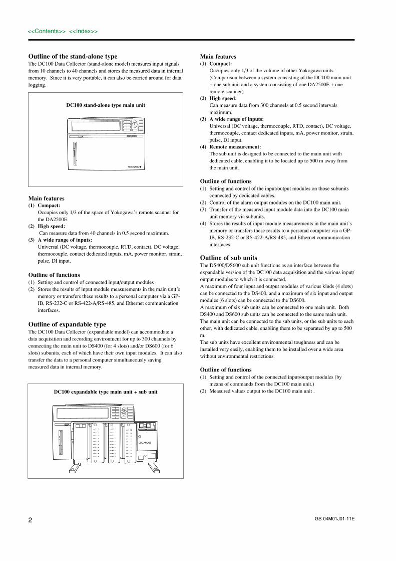
Outline of the stand-alone typeThe DC100 Data Collector (stand-alone model) measures input signalsfrom 10 channels to 40 channels and stores the measured data in internalmemory. Since it is very portable, it can also be carried around for datalogging.
DC100 stand-alone type main unit
Main features(1) Compact:
Occupies only 1/3 of the space of Yokogawa’s remote scanner forthe DA2500E.
(2) High speed: Can measure data from 40 channels in 0.5 second maximum.
(3) A wide range of inputs:Universal (DC voltage, thermocouple, RTD, contact), DC voltage,thermocouple, contact dedicated inputs, mA, power monitor, strain,pulse, DI input.
Outline of functions(1) Setting and control of connected input/output modules(2) Stores the results of input module measurements in the main unit’s
memory or transfers these results to a personal computer via a GP-IB, RS-232-C or RS-422-A/RS-485, and Ethernet communicationinterfaces.
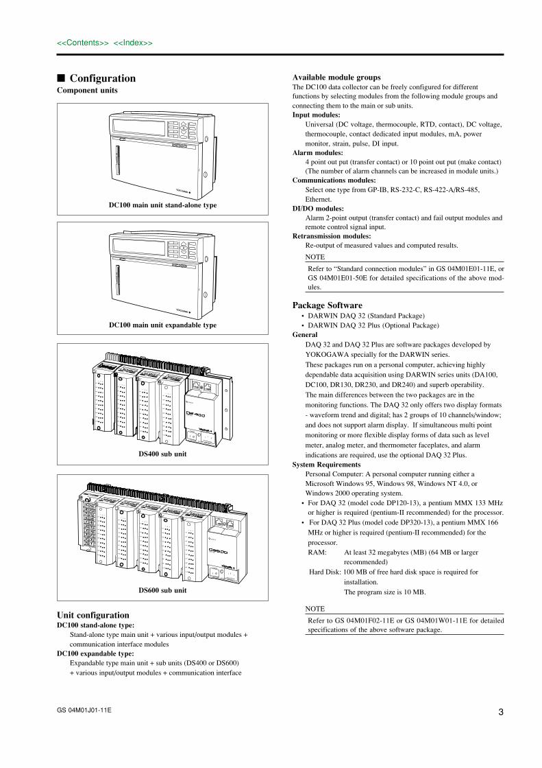
Outline of expandable typeThe DC100 Data Collector (expandable model) can accommodate adata acquisition and recording environment for up to 300 channels byconnecting the main unit to DS400 (for 4 slots) and/or DS600 (for 6slots) subunits, each of which have their own input modules. It can alsotransfer the data to a personal computer simultaneously savingmeasured data in internal memory.
DC100 expandable type main unit + sub unit
CH1b -/B +/A
CH2
CH3
CH4
CH5
CH6
CH7
CH8
CH9
CH10
CH1b -/B +/A
CH2
CH3
CH4
CH5
CH6
CH7
CH8
CH9
CH10
CH1b -/B +/A
CH2
CH3
CH4
CH5
CH6
CH7
CH8
CH9
CH10
GS 04M01J01-11E 3
<<Contents>> <<Index>>
Available module groupsThe DC100 data collector can be freely configured for differentfunctions by selecting modules from the following module groups andconnecting them to the main or sub units.Input modules:
Universal (DC voltage, thermocouple, RTD, contact), DC voltage,thermocouple, contact dedicated input modules, mA, powermonitor, strain, pulse, DI input.
Alarm modules:4 point out put (transfer contact) or 10 point out put (make contact)(The number of alarm channels can be increased in module units.)
Communications modules:Select one type from GP-IB, RS-232-C, RS-422-A/RS-485,Ethernet.
DI/DO modules:Alarm 2-point output (transfer contact) and fail output modules andremote control signal input.
Retransmission modules:Re-output of measured values and computed results.
NOTE
Refer to “Standard connection modules” in GS 04M01E01-11E, orGS 04M01E01-50E for detailed specifications of the above mod-ules.
Package Software• DARWIN DAQ 32 (Standard Package)• DARWIN DAQ 32 Plus (Optional Package)
GeneralDAQ 32 and DAQ 32 Plus are software packages developed byYOKOGAWA specially for the DARWIN series.
These packages run on a personal computer, achieving highlydependable data acquisition using DARWIN series units (DA100,DC100, DR130, DR230, and DR240) and superb operability.The main differences between the two packages are in themonitoring functions. The DAQ 32 only offers two display formats- waveform trend and digital; has 2 groups of 10 channels/window;and does not support alarm display. If simultaneous multi pointmonitoring or more flexible display forms of data such as levelmeter, analog meter, and thermometer faceplates, and alarmindications are required, use the optional DAQ 32 Plus.
System RequirementsPersonal Computer: A personal computer running either aMicrosoft Windows 95, Windows 98, Windows NT 4.0, orWindows 2000 operating system.
• For DAQ 32 (model code DP120-13), a pentium MMX 133 MHzor higher is required (pentium-II recommended) for the processor.
• For DAQ 32 Plus (model code DP320-13), a pentium MMX 166MHz or higher is required (pentium-II recommended) for theprocessor.RAM: At least 32 megabytes (MB) (64 MB or larger
recommended)Hard Disk: 100 MB of free hard disk space is required for
installation.The program size is 10 MB.
NOTE
Refer to GS 04M01F02-11E or GS 04M01W01-11E for detailedspecifications of the above software package.
ConfigurationComponent units
DC100 main unit stand-alone type
DC100 main unit expandable type
STATUS
SUB UNIT
100-240VAC 50/60Hz 70VA MAX
POWER
CH1
CH2
CH3
CH4
CH5
CH6
CH7
CH8
CH9
CH10
b -/B -/A
b -/B -/A
CH1
CH2
CH3
CH4
CH5
CH6
CH7
CH8
CH9
CH10
b -/B -/A
CH1
CH2
CH3
CH4
CH5
CH6
CH7
CH8
CH9
CH10
b -/B -/A
CH1
CH2
CH3
CH4
CH5
CH6
CH7
CH8
CH9
CH10
DS400 sub unit
STATUS
SUB UNIT
100-240VAC 50/60Hz 70VA MAX
POWER
CH1
CH2
CH3
CH4
CH5
CH6
CH7
CH8
CH9
CH10
b -/B -/A
b -/B -/A
CH1
CH2
CH3
CH4
CH5
CH6
CH7
CH8
CH9
CH10
b -/B -/A
CH1
CH2
CH3
CH4
CH5
CH6
CH7
CH8
CH9
CH10
CH1
CH2
CH3
CH4
CH5
CH6
CH7
CH8
CH9
CH10
b -/B -/A
b -/B -/A
CH1
CH2
CH3
CH4
CH5
CH6
CH7
CH8
CH9
CH10
DS600 sub unit
Unit configurationDC100 stand-alone type:
Stand-alone type main unit + various input/output modules +communication interface modules
DC100 expandable type:Expandable type main unit + sub units (DS400 or DS600)+ various input/output modules + communication interface

GS
04M01J01-11E
4 <<
Contents>
> <
<Index>
>
DARWINDAQ 32
InTouchfor
DARWIN2000
DARWINDAQ 32 Plus
DAQLOGGER
package software
Personal computerSet-up and control
software
DC100 main unit
Module
Input
Install
Communication
interface cable
RS-422-A/485
module
RS-232-C
module
GP-IB
module
mA(current)
module
Strain
module
DI
module
UniversalDC V/TC/DI
module
4-20 mA
module1-5 V module
Pulse
module
Communication interface moduleInput moduleRetransmission module
currentACContact StatusRTDTCDC V
DI/DO
module
Alarm output
module
I/O module
Power
module
STRAINPULSE
No
alar
m m
odul
e or
DI/D
O m
odul
eca
n be
conn
ecte
d to
ther
ight
side
of t
his
inpu
t mod
ule.
A~
Ethernet
module
DC100 stand-alone type system configuration
GS
04M01J01-11E
5
<<
Contents>
> <
<Index>
>
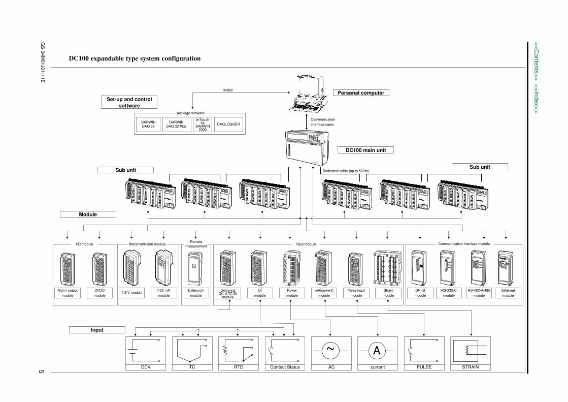
DC100 expandable type system configuration
Personal computerSet-up and control
software
DC100 main unit
Sub unitSub unit
Module
Input
Install
Communication
interface cable
STRAINPULSEcurrentACContact StatusRTDTCDCV
Strain
module
Pulse input
module
mA(current)
module
Power
module
DI
module
UniversalDC V/TC/DI
module
Extension
module
4-20 mA
module1-5 V module
Input moduleRemote
measurementRetransmission module
DI/DO
module
Alarm output
module
I/O module
Dedicated cable (up to 500m)
No
alar
m m
odul
e or
DI/D
O m
odul
eca
n be
conn
ecte
d to
ther
ight
side
of t
his
inpu
t mod
ule.
A~
RS-422-A/485
module
RS-232-C
module
GP-IB
module
Communication interface module
Ethernet
module
DARWINDAQ 32
InTouchfor
DARWIN2000
DARWINDAQ 32 Plus
DAQLOGGER
package software
GS 04M01J01-11E6
<<Contents>> <<Index>>
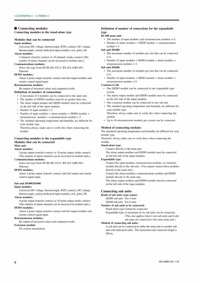
Connecting modulesConnecting modules to the stand-alone type
Modules that can be connectedInput modules:
Universal (DC voltage, thermocouple, RTD, contact), DC voltage,thermocouple, contact dedicated input modules, mA, pulse, DI.
Alarm modules:4 channels (transfer contact) or 10 channels (make contact) (Thenumber of alarm channels can be increased in module units.)
Communications modules:Select one type from GP-IB, RS-232-C, RS-422-A/RS-485,Ethernet.
DI/DO modules:Alarm 2-point output (transfer contact) and fail output modules andremote control signal input
Retransmission modules:Re-output of measured values and computed results
Definition of number of connections• A maximum of 4 modules can be connected to the main unit.• The number of DI/DO modules must be no greater than one.• The alarm output module and DI/DO module must be connected
on the left side of the input modules.• Number of input modules ≤ 4• Number of input modules + alarm modules + DI/DO module +
retransmission modules + communications module ≤ 4• The standard operating temperature and humidity are different for
each module type.Therefore,always make sure to verify this when connecting themodule.
Connecting modules to the expandable typeModules that can be connectedMain unitAlarm modules:
4-point output (transfer contact) or 10-point output (make contact)(The number of alarm channels can be increased in module units.)
Communications modules:Select one type from GP-IB, RS-232-C, RS-422-A/RS-485,Ethernet.
DI/DO modules:Alarm 2-point output (transfer contact) and fail output and remotecontrol signal input.
Sub unit DS400/DS600Input modules:
Universal (DC voltage, thermocouple, RTD, contact), DC voltage,thermocouple, contact dedicated input modules, mA, pulse, DI.
Alarm modules:4-point output (transfer contact) or 10-point output (make contact)(The number of alarm channels can be increased in module units.)
DI/DO modules:Alarm 2-point output (transfer contact) and fail output modules andremote control signal input
Retransmission modules:Re-output of measured values and computed results
Extension module:For remote measurment
Definition of number of connections for the expandabletypeDC100 main unit:
• The number of input modules and retransmission modules is 0.• Number of alarm modules + DI/DO module + communications
module ≤ 4Sub unit DS400:
• The maximum number of modules per slot that can be connectedis 4.
• Number of input modules + DI/DO module + alarm modules +retransmission modules ≤ 4
Sub unit DS600:• The maximum number of modules per slot that can be connected
is 6.• Number of input modules + DI/DO module + alarm modules +
retransmission modules ≤ 6Common to all:
• One DI/DO module can be connected to one expandable typesystem
• The alarm output module and DI/DO module must be connectedon the left side of the input modules.
• One extension module can be connected to one sub unit.• The standard operating temperature and humidity are different for
each module type.Therefore, always make sure to verify this when connecting themodule.
• Up to 30 retransmission modules per system can be connected.
Method of connecting modulesThe standared operating temperature and humidity are different for eachmodule type.Therefore, always make sure to verify these when connecting themodule.Stand-alone type:
Connect directly to the main unit.The alarm output modlues and DI/DO module must be connectedon the left side of the input modules.
Expandable type:Connect the input modules, retransmission modules, or extensionmodule directly to the sub unit. (You cannot connect these modulesdirectly to the main unit.)Connect the alarm modules, communications module and DI/DOmodule directly to the main unit.The alarm output modlues and DI/DO module must be connectedon the left side of the input modules.
Connecting sub unitsKinds of sub units (type name):
DS400 sub unit: For 4 slotsDS600 sub unit: For 6 slots
Number of sub units to be connected:Stand-alone type:Cannot be connected.Expandable type:A maximum of six sub units can be connected.
(This also applies when 4-slot sub units and 6-slotsub units are connected to the same main unit.)
Method of connecting sub units:A sub unit can be connected to either the main unit or another subunit with dedicated cable. The maximum total extension length is500 m.

GS 04M01J01-11E 7
<<Contents>> <<Index>>
Standard specificationsGeneral specificationsConstructionInstallation method:
Floor mounting: Use the stand at the bottom of each unit.Direct panel mounting: Screw the unit directly to the panel at the
specified points.Mount the DC100 usingthe rack-mounting brackets after removingthe knobs.
Rack mounting: Use the dedicated mounting brackets.Regardless of which mounting method you use,be sure to install the units in an upright position.)
Materials:Steel plate, aluminum castings, plastic moldings
Paint color:Base unit: Lamp black (equivalent to Munsell 0.8Y2.5/0.4)
Slate gray light (equivalent to Munsell 0.1PB4.6/0.2)
Modules: Slate gray light (equivalent to Munsell 0.1PB4.6/0.2)
External dimensions:Stand-alone type main unit:
Approx. 338 (W) × 236 (H) × 157 (D) mmExpandable type main unit:
Approx. 338 (W) × 236 (H) × 157 (D) mmDS400 sub unit: Approx. 336 (W) × 165 (H) × 100 (D) mmDS600 sub unit: Approx. 422 (W) × 176 (H) × 100 (D) mm
Weight:Stand-alone type main unit:
Approx. 5.3 kg (with 2 input modules, 1 alarmoutput module, and 1 communications moduleinstalled)Approx. 3.5 kg*
Expandable type main unit:Approx. 5.3 kg (with 4 input/output modulesinstalled)Approx. 3.5 kg*
DS400 sub unit: Approx. 2.5 kg (with 4 input/output modulesinstalled) Approx. 0.9 kg*
DS600 sub unit: Approx. 3.5 kg (with 6 input/output modulesinstalled) Approx. 1.1 kg*
*: is the weight of each unit without modules installed.
InputMeasurement range:
NOTE
Refer to “Standard modules for the DC100 data collector” in GS04M01E01-11E for detailed specifications of the measurementrange.
Measurement interval:Selectable from 0.5, 1, 2, 3, 4, 5, 6, 10, 12, 15, 20, 30, and 60 secStand-alone type:
Max 40 channels/500 ms (when the softwareprovided is used)
Expandable type:Max 300 channels/500 ms (when the softwareprovided is used)
The measurement interval depends on the minimum measurementinterval (when modules with different minimum intervals areinstalled together, the measurement interval is determined bywhichever module has the maximum interval).
A/D integration period (dependent on the module):Selectable from 20 ms (50 Hz), 16.7 ms (60 Hz), 100 ms (10 Hz),and auto switching (unavailable for a DC power supply model).
AlarmNumber of settings:
Up to four settings can be made for each channel.Kinds of alarms:
Selection from higher limit, lower limit, difference higher limit,difference lower limit, higher limit of rate of change, lower limitof rate of change.
Rate of change alarm time interval:Can be set to measurement interval × 1 to 15 (common to bothrising and falling limits)
Output mode:Excitation/non-excitation selection, AND/OR mode selection, andoutput hold/non-hold specification can be made. (common to allchannels)Six reflash alarm output contacts can be specified.
Number of alarm output points:Stand-alone type:
2 points (DI/DO module) to 30 points maxExpandable type:
Up to 30 points can be connected to the DC100main unit (the number of alarm points can beincreased in module units).By connecting sub units, (the number of alarmpoints can be increased in module units).
Number of alarm output modules that can be connected:Stand-alone type:
The number of alarm points can be increased inmodule units.
Expandable type:Up to 4 modules can be connected to the DC100main unit, up to 6 modules can be connected tothe DS600 sub unit. The number can beincreased by adding sub units.
Memory Function SectionBuffer memory: SRAM buffer memory (lithium battery backup
for approx. 8 years)Measured values are saved in internal memoryand then transferred to a floppy disk.
Number of Floppy Disk Drive:3.5-inch floppy disk drive × 1
Floppy Disk Recording Density:2HD or 2DD
Floppy Disk Capacity:1.2 MB, 1.44 MB or 720 kB
Memory Capacity:Selected from 1 MB (standard), 2 MB or 4 MBat time of order
Data save: Setting values, measured values and computedvalues
Data save Format:Binary for measured and computed valuesASCII for setting values
Data Acquisition Method:Division (division into 2, 4, 8, or 16) or Datalength
Data Acquisition Operations:Single, repeat, or rotary
Data Acquisition Triggers:Free or trigger mode (utilizes the event/actionfunction)

GS 04M01J01-11E8
<<Contents>> <<Index>>
DC power supply sectionRated supply voltage:
12 to 28 VDCUsable supply voltage range:
10 to 32 VDCPower consumption:
max. approx 30 VA (DC100)max. approx 25 VA (DS400, DS600)
Terminal: Dedicated connectorOthers: DC power supply only. However, when
purchasing the DC100 DC power operationmodel, attached the dedicated AC adapter asstandard accessory.
AC adapter for DC power modelRated supply voltage:
100 to 240 VAC (free supply voltage selection)Usable supply voltage:
90 to 250 VACRated supply frequency:
50/60 HzPower consumption:
max. approx 90 VA
OthersClock: With calendar function (Western calendar),
Clock accuracy is ±100 ppmSystem alarm: Contact output (when DI/DO module is
connected)Set value backup:
Lithium battery backup (approx. 8 years),excluding clock function
Insulation resistance:At least 20 MΩ between each terminal andground (measured with 500 VDC)
Withstand voltage:Between AC power supply terminal and case ofDC100 main unit: 1500 VAC (50/60 Hz) for oneminuteBetween DC power supply terminal and case ofDC100 main unit: 1000 VAC (50/60 Hz) for oneminuteBetween input terminal and case of DA100 mainunit:1500 VAC (50/60 Hz) for one minuteBetween output terminal and case of DA100main unit:2300 VAC (50/60 Hz) for one minute
Sample Rate: 0.5 s, 1 s, 2 s, 3 s, 4 s, 5 s, 6 s, 10 s, 12 s, 15 s,20 s, 30 s, 1 min., 2 min., 3 min., 4 min., 5 min.,10 min., 30 min., or 60 min.LOGIC (event/action function)
Recording Data Length in the Data Length Data AcquisitionMethod (unit: data item/channel):
10, 20, 30, 40, 50, 100, 200, 300, 400, 500, 1 k,2 k, 3 k, 4 k, 5 k, 10 k, 20 k, 30 k, 40 k, 50 k,100 k
Standard computation functionsComputation functions:
Difference between arbitrary channels, linear scaling, movingaverage, pulse integration (when pulse module is installed)
Scaling:Ranges for which scaling can be done:
DC voltage, thermocouple, RTD, contact, strain,mA.
Scaling range: –30000 to +30000Decimal point: Can be set freely.Measurement accuracy for scaling:
Measurement accuracy for scaling (digits) =Measurement accuracy (digits) × Scaling span(digits)/Measurement span (digits) + 2 digits(Numbers below the decimal point are dis-carded.)
Moving average:The moving average results for between 2 to 64 (2n: n is nonnega-tive integer) scans are computed.
Communications functionsCommunication modules:
GP-IB, RS-232-C, RS-422-A/RS-485, Ethernet communicationsinterface modules.
Output functionsDI/DO module:
Internal alarm 2 points, fail, and file end output functionRetransmission modules:
Re-output of measured values and computed results
AC power supply sectionRated supply voltage:
100 to 240 VAC (free supply voltage selection)Usable supply voltage range:
90 to 250 VACRated supply frequency:
50/60 HzPower consumption:
Stand-alone type main unit (when 4 connectable modules are installed)max approx. 90 VA
Expandable type main unit (when 4 connectable modules are installed)max approx. 90 VA
DS400 sub unit (when 4 connectable input/output modules are installed) max approx. 55VA
DS600 sub unit (When 6 connectable input/output modules are installed) max approx. 70 VA

GS 04M01J01-11E 9
<<Contents>> <<Index>>
Normal operation conditionsSupply voltage: 90 to 250 VAC, 10 to 32 VDCSupply frequency: 50 Hz ± 2%, 60 Hz ± 2%Ambient temperature:
Stand-alone type main unitexpandable type main unitWhen floor, Panal, Rack, mounted and Desk top: 5 to 40°CDS400/DS600 sub unitWhen floor-mounted and Desk top: 0 to 50°CWhen panel-mounted: –0 to 60°CWhen Rack-mounted: 0 to 50°CWhen DC operation: 0 to 50°C
Ambient humidity:
Temperature
–10 to 40˚C
40 to 50˚C
50 to 60˚C
Humidity
20 to 80% RH
10 to 50% RH
5 to 30% RH
* no ice formationVibration: 10 to 60 Hz 0.2 m/s2
Shock: Not allowedMagnetic field: 400 A/m max (50/60 Hz)Position: Mount the unit left-right horizontally or
vertically, as a general rule.Warm-up time: At least 30 minutes after power switch-on
Standard performanceReference operation state:
23 ± 2°C, 55 ± 10% RH, supply voltage: 90 to250 VAC, supply frequency: 50/60 Hz ± 1%,Warmup: At least 30 minutes; When operating,the system must not adversely affect the operationof other measuring instruments by generatingvibration, for example. enerating vibration, forexample.
NOTE
Refer to “Standard connection modules for the DC100 data collec-tor” in GS 04M01E01-11E for detailed specifications of the mea-surement accuracy.
Effect of Operation ConditionsAmbient temperature:
Variation for a temperature change of 10°Cwithin ±(0.1% of rdg + 1 digit)±(0.2% of span + 1 digit) for Cu 10 Ω
Voltage variation: Within ±1 digit over the range of 90 to 132, or180 to 250 VAC (frequency 50/60 Hz)
External magnetic field:Variation with respect to AC (50/60 Hz) and DCmagnetic fields of 400 A/m ... Within ±(0.1% ofrdg + 10 digits)
Radio wave: Within ±(1% of span) at 1m from 150 MHz or460 MHz field
Signal source resistance:Variation with respect to signal source resistance+ 1 kΩ change
(1) Voltage 2 V range or below ... Within ±10 µV 6 V range or above ... Within ±0.1% of rdg
(2) ThermocoupleWithin ±10 µV; However, it must be within ±100µ when burnout is specified.
(3) RTD Variation with respect to change of 10 Ω per wire(when all three wires are the same resistancevalue)
Indication ... Within ±(0.1% of rdg + 1 digit)Variation in indication with respect to adifference of 40 mΩ in the resistancebetween conductors (max difference between3 wires) ... Approx. 0.1°C
Mounting position:Variation when the unit is mounted horizontallyon a panel ... Within ±(0.1% of rdg + 1 digit)
Vibration: Variation when sinusoidal vibration ofacceleration 0.2 m/s2 is applied for 2 hours in eachof the 3 axial directions over a frequency range of10 to 60 Hz ... Within ±(0.1% of rdg + 1 digit)
Transportation and storage conditionsThese refer to the environmental conditions existing during transporta-tion and storage from the time of shipment from the factory untilcommencement of use, and also during transportation and storage in thecase of a temporary period of non-use.If the environmental conditions are maintained within the specifiedrange, the unit will not incur permanent damage, and can be returned toa normal working condition (re-adjustment may be required in somecases).
Ambient temperature: –20 to 60°CHumidity: 5 to 95% RHVibration: 10 to 60 Hz 4.9 m/s2 maxShock: 392 m/s2 max (in packed condition)
GS 04M01J01-11E10
<<Contents>> <<Index>>
/M1: MATH FunctionComputation typesTypes:
Four arithmetical operations, SQR (square root), ABS (absolutevalue), LOG (common logarithm), LN (natural logarithm), EXP(exponent), statistical computation*, logical computation (AND,OR, NOT, and XOR), relational computation, exponentiation,previously-measured value reference, hold**, and reset
*Statistical computationCLOG: Computation process of simultaneously
measured values within a group (total, maxi-mum, minimum, average, and maximum -minimum)
TLOG: Computation process of a specific channel overtime axis (total, maximum, minimum, average,and maximum - minimum)
Statistical computation interval:Set by the event/action function (effective when/M1 option is selected)
**Hold Temporary suspending of computation and temporary hold ofthe computed result
During statistical computation, resume the computation from thehold point after the hold is released. (effective when /M1 option isselected)
Number of channels for computing (Number of channels that canbe allocated for computational purposes.):
Stand-alone type: 30ch maximumExpandable type: 60ch maximum
Computation interval:Every measurement interval (except when the computationbecomes too difficult to be processed every measured interval, inwhich case an alarm is generated)
Significant digits during computation:±1038
Significant digits of the computed result:–9999999 to +99999999 (The decimal point can be set to none orhave 1 to 4 digits on the right of the decimal point)
Computation start/stop:Can be controlled by personal computer, time specified, remotecontrol signal (DI/DO module), and alarm status
Temporary hold of the computed result:Can be controlled by remote control signal (DI/DO module), andalarm status
Other functions included in the math function:Remote RJCInput type: Thermocouple (TC)Accuracy: (Twice the measurement accuracy of the
standard thermocouple input) + (temperaturedifference between the terminal of the remoteterminal section and thermocouple section formeasuring the remote terminal temperature)
Thermocouple burnout: not selectable
/D2: F degree Display
/L1: Summer/Winter Time Display
/C5: External Mass Storage Interface Function(SCSI*1)
By installing the external mass storage interface (SCSI) option tothe DC100, you can connect MO/Zip/Jaz/PD disk drives.MO/Zip/Jaz/PD disk drive connected to the DC100 on powerup isautomatically detected and can be usedas external medium.The external mass storage interface (SCSI) option is a communica-tion interface for saving files created in the DC100 internal RAM(such as measurement data files, report files, and periodic files)onto the MO/Zip/Jaz/PD disk. It is also used for loading files fromthe disks.In addition, MO/Zip/Jaz/PD disks allow transferring of filesbetween the DC100 and the PC without physically connecting thetwo using communication cables.
*1: SCSI (Small Computer System Interface)It is an interface standard for connecting the computer to peripheraldevices such as hard disks and scanners.It is a communication standard (ANSI X3.131-1986) adopted byANSI (American National Standards Institute) in July 1986.The external mass storage interface (SCSI) option for the DC100can connect only to MO/Zip/Jaz/PD disk drives meeting thefollowing specifications.
Supported modelsData Collector DC100(DC100-1, DC100-2 with /C5 option)
Connection with MO/ZIP disk drive• Automatically detect MO/Zip/Jaz/PD disk drive connected on
power up.• Manual detection after power up also possible.
SCSI controllerWD33C93A made by Western Digital
SCSI pathSCSI (conforms to ANSI X3.131-1986)
Terminating resistanceBuilt-in passive terminator (Terminator ON fixed)
Connector on the DC100D-sub half-pitch connector 50-pins female
Connector pin assignmentUnbalanced transfer type (Single-ended path)
SCSI cableCable that is 3 m or less between the DC100 and the SCSI device.
MediaMO/Zip/Jaz/PD
Maximum connectionsUp to 7 devices excluding the DC100
DC100 ID numberFixed to 7
ID numbers for MO/Zip/Jaz/PD disk drivesAny ID number
NOTE
If connecting multiple devices, each device must be assigned with aunique ID number.

GS 04M01J01-11E 11
<<Contents>> <<Index>>
Contmction between SCSI devices• Follow the manuals that come with the MO/Zip/Jaz/PD drives in
connecting the devices.• DC100 can access each of the multiple SCSI devices by
specifying the ID number.• Attach a terminator to the device on the end of the SCSI chain.
Certain devices have built-in terminators that can be turned onwith a switch.
• SCAM*2 is not supported.*2: SCAM (SCSI Configured AutoMatically) is a standard created
by Adaptec and Microsoft to automatically assign unique SCSIIDs.Not all SCSI devices support this standard.
Magneto Optical Disk standard• 128 MB, 230 MB, 540 MB, 640 MB magneto optical disks are
standardized*3 media. Media from different manufactures arecompatible as long as they conform to the standard.
• See the instruction manual for the MO drive to see what types ofmedia are supported.
Storage Space of Media (Bytes) 128 M
Compatible Standard
Rotation Control Method
Bytes per sector
Track Pitch (µ)
ISO10090
CAV
512
1.6
230 M
ECMA-201
ZCAV
512
1.39
540 M
ISO15041
ZCAV
512
1.1
640 M
ISO15041
ZCAV
2048
1.1
*3: Other Magneto Optical disk formats are HS standard (Medium is90 mm in diameter and holds 650 MB) which uses magneticmodulation method and PD format (Medium is 120 mm indiameter and holds 650 MB) which is a phase change type.
Devices that have tested
Product Name Model
SCSI-2 Compatible model
iomega Zip 100, Zip 250
iomega Jaz 1GB
Panasonic PD/CD-ROM
Manufacturer
Fujitsu
Iomega Co.,Ltd.
Iomega Co.,Ltd.
Panasonic
MO drive
Zip drive
Jaz drive
PD drive
NOTE Some of the MO/Zip/Jaz/PD disk drives need terminators. Followthe instruction manual for the particular disk drive.
Features of the media (MO/Zip/Jaz/PD disk)• The DC100 recognizes up to 272 files for each MO/Zip/Jaz/PD
disk.• Set-up data files can be directly written to the MO/Zip/Jaz/PD
disk through the SCSI.• Measurement data file, report computation files, and periodic files
are stored once in the DC100 internal RAM, then copied to theMO/Zip/Jaz/PD disk through the SCSI.Cannot copy between SCSI devices.
• Deleting data files.• Formatting the MO/Zip/Jaz/PD disk.
Directory structure of the external SCSI media• All data are saved/loaded to subdirectory “DIR 0 .”• Subdirectory “DIR 0” is automatically created if it does not exist
on the external medium.• No limit on the number of files on the external medium.
Data processing with the personal computer• Data file can be displayed, analyzed, or converted (Excel/Lotus/
ASCII) with the DAQ 32 software that is provided with theDC100.
• Advanced data analysis on multiple channels can be performedsimultaneously with the DAQ 32 Plus software.
NOTE
For information on the software specification, see “DARWIN Soft-ware Package Specification (GS 04M01F02-11E).”

GS 04M01J01-11E12
<<Contents>> <<Index>>
Type name and specification codeData collector DC100
Model
DC100
Type
Software
Memory
FDD
Power Supply voltage
Power Inlet & Power Cable
Optional Features
Suffix Code
-1
-2
2
-1
-2
-3
1
-1
-2*
D
F
R
S
W
Optional Code
/M1
/M3
/C5
/D2
/L1
/FC
Description
Data collector
Stand-alone type
Expandable type main unit
DARWIN DAQ 32 (English, French, German)
Internal memory 1 Mbyte (standard specification)
Internal memory 2 Mbyte
Internal memory 4 Mbyte
Floppy disk drive
100 VAC to 240 VAC
12 VDC to 28 VDC
3-pin power inlet w/UL, CSA cable
3-pin power inlet w/VDE cable
3-pin power inlet w/SAA cable
3-pin power inlet w/BS cable
3-pin power inlet w/screw terminal
Mathematical function
Report function
External mass storage interface
F degree display
Summer/winter time
DARWIN DAQ 32 is supplied with floppy disks
*: DC power operation only. However, when specifying this code, the dedicated AC adapter is attached as standard accessory.
Power cable of AC adapter must be specified from the code of power inlet & power cable, however W can not be specified.
Subunit DS400/DS600
Model
DS400
DS600
Type
Power Supply
Power Inlet & Power Cable
Suffix Code
-00
-1
-2
D
F
R
S
W
Y
Optional Code Description
4 slots subunit for inputs and alarm output
6 slots subunit for inputs and alarm output
Always-00
100 VAC to 240 VAC
12 VDC to 28 VDC (always specify Y for the power cable)
3-pin power inlet w/UL, CSA cable
3-pin power inlet w/VDE cable
3-pin power inlet w/SAA cable
3-pin power inlet w/BS cable
3-pin power inlet w/screw terminal
Dedicated connector for DC power operation w/o power cable
GS 04M01J01-11E 13
<<Contents>> <<Index>>
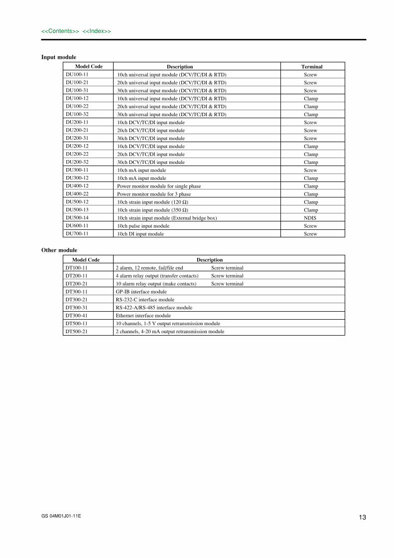
Input module
Model Code
DU100-11
DU100-21
DU100-31
DU100-12
DU100-22
DU100-32
DU200-11
DU200-21
DU200-31
DU200-12
DU200-22
DU200-32
DU300-11
DU300-12
DU400-12
DU400-22
DU500-12
DU500-13
DU500-14
DU600-11
DU700-11
Description
10ch universal input module (DCV/TC/DI & RTD)
20ch universal input module (DCV/TC/DI & RTD)
30ch universal input module (DCV/TC/DI & RTD)
10ch universal input module (DCV/TC/DI & RTD)
20ch universal input module (DCV/TC/DI & RTD)
30ch universal input module (DCV/TC/DI & RTD)
10ch DCV/TC/DI input module
20ch DCV/TC/DI input module
30ch DCV/TC/DI input module
10ch DCV/TC/DI input module
20ch DCV/TC/DI input module
30ch DCV/TC/DI input module
10ch mA input module
10ch mA input module
Power monitor module for single phase
Power monitor module for 3 phase
10ch strain input module (120 Ω)
10ch strain input module (350 Ω)
10ch strain input module (External bridge box)
10ch pulse input module
10ch DI input module
Terminal
Screw
Screw
Screw
Clamp
Clamp
Clamp
Screw
Screw
Screw
Clamp
Clamp
Clamp
Screw
Clamp
Clamp
Clamp
Clamp
Clamp
NDIS
Screw
Screw
Other module
Model Code
DT100-11
DT200-11
DT200-21
DT300-11
DT300-21
DT300-31
DT300-41
DT500-11
DT500-21
Description
2 alarm, 12 remote, fail/file end Screw terminal
4 alarm relay output (transfer contacts) Screw terminal
10 alarm relay output (make contacts) Screw terminal
GP-IB interface module
RS-232-C interface module
RS-422-A/RS-485 interface module
Ethernet interface module
10 channels, 1-5 V output retransmission module
2 channels, 4-20 mA output retransmission module

GS 04M01J01-11E14
<<Contents>> <<Index>>
Accessories
Model Code
DV100-011
DV100-012
DV200-000
DV200-001
DV200-002
DC200-005
DV200-010
DV200-020
DV200-050
DV200-100
DV200-200
DV200-300
DV200-400
DV200-500
DV250-001
DV300-011
DV300-012
DV300-101
DV300-102
DV300-251
DV300-252
DV400-011
DV400-012
DV400-015
DV400-071
DV450-001
DV500-001
DV500-002
DV500-003
DV500-004
Description
Extension module
Extension base unit
Extension cable (0.5 m)
Extension cable (1 m)
Extension cable (2 m)
Extension cable (5 m)
Extension cable (10 m)
Extension cable (20 m)
Extension cable (50 m)
Extension cable (100 m)
Extension cable (200 m)
Extension cable (300 m)
Extension cable (400 m)
Extension cable (500 m)
Cable adapter
Shunt resistor 10 Ω for screw input terminal
Shunt resistor 10 Ω for clamped input terminal
Shunt resistor 100 Ω for screw input terminal
Shunt resistor 100 Ω for clamped input terminal
Shunt resistor 250 Ω for screw input terminal
Shunt resistor 250 Ω for clamped input terminal
Rack mount kit (DA100 exp./DS400) for ANSI
Rack mount kit (DA100 stand./DS600) for ANSI
Rack mount kit (DC100 stand./exp) for ANSI
Panel mount fittings for DC100
DIN-NDIS strain conversion cable
AC adapter for DC operation model with UL, CSA cable
AC adapter for DC operation model with VDE cable
AC adapter for DC operation model with SAA cable
AC adapter for DC operation model with BS cable
Package software
Model Code
DP120-13
DP320-13
DP810- 1E
VA510-0 -2
Description
DARWIN DAQ 32 software (Windows 95/98/NT 4.0/2000) (comes standard)
DARWIN DAQ 32 Plus software (Windows 95/98/NT 4.0/2000) (optional)
InTouch for DARWIN 2000 for process monitoring software (Windows NT 4.0) (optional)
DAQLOGGER for multi-channel data logging software (Windows 95/98/NT 4.0/2000) (optional)

GS 04M01J01-11E 15
<<Contents>> <<Index>>
Wiring Input Signal Lines (to Universal and DCV/TC/DI input modules)Terminals
Screw type terminal Clamp type terminal
+-
ABb
DC voltage • TC •contact
RTD*
ABb
CH1CH2
CH10
CH1CH2
CH3CH4
CH9CH10
+-
*There are no RTD input terminals on the DCV/TC/DI input module.
Wiring Diagram
DC voltage input
Compensation lead
DC current input
Shunt resistorNote:For 4 to 20 mA input, shunt resistance value should be 250 Ω ± 0.1%
10 Ω* max./leadwire Three wire resistances should be approx. equal.
*10 Ω max. for Pt 100 Ω and Pt 50 Ω, 1 Ω max. for Cu 10 Ω.
DC input
RTD inputTC input
DC voltage input/DI input (contact)
b AB
AbB
+
-
+-+-
+
-
+-
Wiring Alarm Output SIgnal Lines (to DI/DO and Alarm output modules)Terminals
NO C
12
NCFail output (transfer contact)
Alarm output (transfer contact)
Remote controlsignal input
DT100-11
File Alarmoutput
NO C
12
4
NC
3
Alarm output (transfer contact)
Alarm output (transfer contact)
DT200-11 NO C
12
10
Alarm output (make contact)
DT200-21
Contact capacity:250 VDC/0.1 A (with aresistor load)250 VAC/2 A (with aresistor load)30 VDC/2 A (with a resistorload)
Fail output:becomes de-activated whenan error is detected in thesystem.
GS 04M01J01-11E16
<<Contents>> <<Index>>
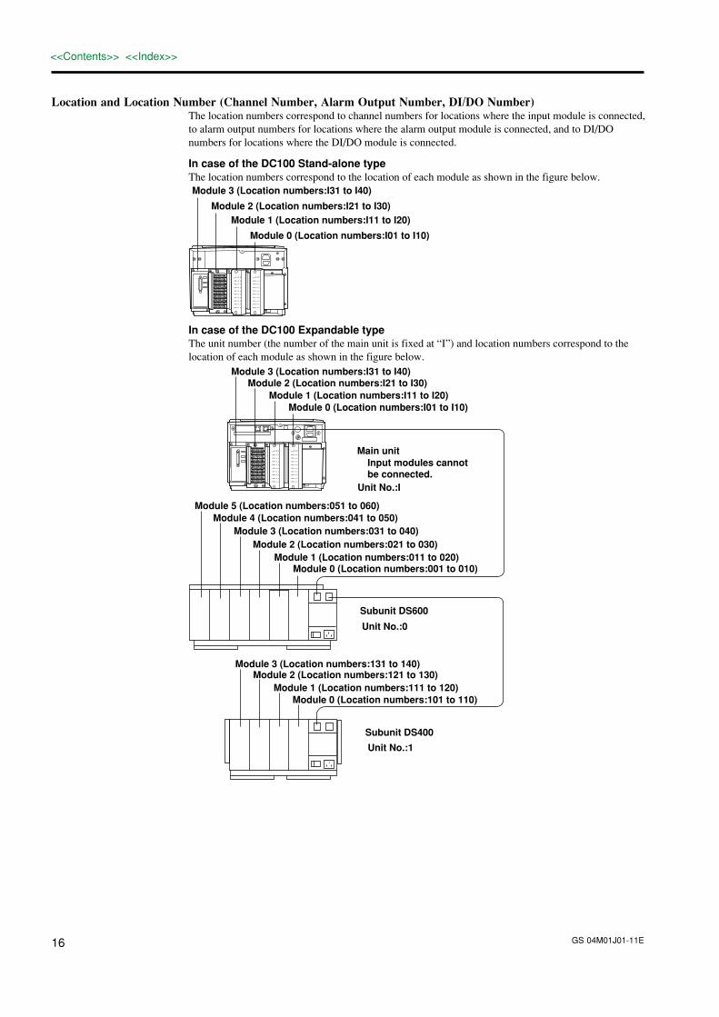
Location and Location Number (Channel Number, Alarm Output Number, DI/DO Number)The location numbers correspond to channel numbers for locations where the input module is connected,to alarm output numbers for locations where the alarm output module is connected, and to DI/DOnumbers for locations where the DI/DO module is connected.
In case of the DC100 Stand-alone typeThe location numbers correspond to the location of each module as shown in the figure below.
Module 0 (Location numbers:I01 to I10)
Module 1 (Location numbers:I11 to I20)Module 2 (Location numbers:I21 to I30)
Module 3 (Location numbers:I31 to I40)
CH1b -/B +/A
CH2
CH3
CH4
CH5
CH6
CH7
CH8
CH9
CH10
CH1b -/B +/A
CH2
CH3
CH4
CH5
CH6
CH7
CH8
CH9
CH10
In case of the DC100 Expandable typeThe unit number (the number of the main unit is fixed at “I”) and location numbers correspond to thelocation of each module as shown in the figure below.
Module 0 (Location numbers:001 to 010)Module 1 (Location numbers:011 to 020)
Module 2 (Location numbers:021 to 030)Module 3 (Location numbers:031 to 040)
Module 4 (Location numbers:041 to 050)Module 5 (Location numbers:051 to 060)
Main unit
Unit No.:0
Subunit DS600
Module 0 (Location numbers:101 to 110)Module 1 (Location numbers:111 to 120)
Module 2 (Location numbers:121 to 130)Module 3 (Location numbers:131 to 140)
Unit No.:1
Subunit DS400
Input modules cannot be connected.
Module 0 (Location numbers:I01 to I10)Module 1 (Location numbers:I11 to I20)
Module 2 (Location numbers:I21 to I30)Module 3 (Location numbers:I31 to I40)
Unit No.:I
CH1b -/B +/A
CH2
CH3
CH4
CH5
CH6
CH7
CH8
CH9
CH10
CH1b -/B +/A
CH2
CH3
CH4
CH5
CH6
CH7
CH8
CH9
CH10

GS 04M01J01-11E 17
<<Contents>> <<Index>>
Name and Function of Each PartDC100 Stand-alone type (DC100-1)
CH1b -/B +/A
CH2
CH3
CH4
CH5
CH6
CH7
CH8
CH9
CH10
CH1b -/B +/A
CH2
CH3
CH4
CH5
CH6
CH7
CH8
CH9
CH10
DisplayPower switch
FDD
HandleOperation panel
External mass storage interface
Power connector(W:Screw terminal)(DC operation model:Dedicated connector)
Module slotsDC100 Expandable type (DC100-2)
CH1b -/B +/A
CH2
CH3
CH4
CH5
CH6
CH7
CH8
CH9
CH10
CH1b -/B +/A
CH2
CH3
CH4
CH5
CH6
CH7
CH8
CH9
CH10
DisplayPower switch
FDD
HandleOperation panel
Power connector(W:Screw terminal)(DC operation model:Dedicated connector)
Dedicated cable connector
Module slots
External mass storage interface
Subunit DS400
Power connector(W:Screw terminal)(DC operation model:Dedicated connector)
Power switch
Feet
Status indicator
Module connector
Installation holesScrew holes for module installation
Holes for fastening the feet
Lid covering the extensioncable connectorSwitch to set the
unit number
Function groundingterminal (below power switch)
Subunit DS600
Power connector(W:Screw terminal)(DC operation model:Dedicated connector)
Power switch
Feet
Status indicator
Module connector
Installationholes
Screw holes formodule installation
Holes for fasteningthe feet
Lid covering the extension cable connector
Switch to setthe unit number
Function groundingterminal (below power switch)

GS 04M01J01-11E18
<<Contents>> <<Index>>
Dimensional DrawingsDC100 maine unit (stand-alone type/expandable type) Unit: mm
Back panal
145
115
20
290
33871
101 56
622
19
Rack mount Fitting480±1: JIS
10
629
9
150
5050
39
44.5
37.5
44.5
146.
1
310
744
.5
24.5
11.3 32 Front panel482.6±1: ANSI/EIA
JIS ANSI/EIA
If not specified, the tolerance is ±3%. However, in cases of less than 10 mm, the tolerance is ±0.3 mm.

GS 04M01J01-11E 19
<<Contents>> <<Index>>
363.58.75
346+20
32389
4- φ 10
18
271.
525
6.5
2 to
11 23
0+2
0
If not specified, the tolerance is ±3%. However, in cases of less than 10 mm, the tolerance is ±0.3 mm.
Panel mount fittings for DC100
Panel mount
Panel cutout
Front panel
unit: mm

GS 04M01J01-11E20
<<Contents>> <<Index>>
DC100 Stand-alone type/Subunit DS600 Unit: mm
156
168
20
100422
145
2216255
176
115
369
20
DC100 Expandable type/Subunit DS400
165
40
100336
145
223208
5050
115
290
20
If not specified, the tolerance is ±3%. However, in cases of less than 10 mm, the tolerance is ±0.3 mm.

GS 04M01J01-11E 21
<<Contents>> <<Index>>
Rack Mount Fitting (ANSI/EIA)DS400 subunit
482.6453.214.7
177
37.7
101.
6
6.8
DS600 subunit
482.6
453.214.7
177
37.7
101.
6
6.8
Subject to change withut notice.Printed in Japan, 012 (YG)


