General Specifications for Electric...
60
GENERAL SPECIFICATIONS FOR ELECTRICAL INSTALLATIONS ORANGE AND ROCKLAND UTILITIES, INC. Pearl River, New York ROCKLAND ELECTRIC COMPANY Saddle River, New Jersey PIKE COUNTY LIGHT & POWER COMPANY Middletown, New York TELEPHONE: 1-877-434-4100 March 1999 Edition Revision No. 8: January, 2009 Revision No. 9: March, 2009 Underscored text preceded by │symbol denotes a revision in text ► - Denotes revision in a Figure
-
Upload
nguyendang -
Category
Documents
-
view
222 -
download
0
Transcript of General Specifications for Electric...
GENERAL SPECIFICATIONS FOR ELECTRICAL INSTALLATIONS ORANGE AND ROCKLAND UTILITIES, INC. Pearl River, New York ROCKLAND ELECTRIC COMPANY Saddle River, New Jersey PIKE COUNTY LIGHT & POWER COMPANY Middletown, New York TELEPHONE: 1-877-434-4100 March 1999 Edition Revision No. 8: January, 2009 Revision No. 9: March, 2009 Underscored text preceded by │symbol denotes a revision in text ► - Denotes revision in a Figure

ii
We Think You Should Know . . . At Orange and Rockland Utilities, Inc. and subsidiaries, when we say "we're here to help", we mean it. Our responsibility is to provide safe, reliable service to all our customers. So before you start to plan your next project, call your local Orange and Rockland Field Office and ask for the representative in your area. We will provide you with information and assistance, as well as ways to save energy and money. Regardless of whom your electrical energy supplier may be, an applicant for electric service and their designated contractor must adhere to the Specifications for Electrical Installations of Orange and Rockland Utilities, Inc. and subsidiaries. Failure to comply with Orange & Rockland specifications will result in work being redone to conform to the specifications and delays in the completion of the job.
iii
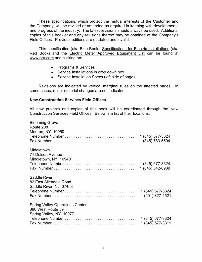
These specifications, which protect the mutual interests of the Customer and the Company, will be revised or amended as required in keeping with developments and progress of the industry. The latest revisions should always be used. Additional copies of this booklet and any revisions thereof may be obtained at the Company's Field Offices. Previous editions are outdated and invalid. This specification (aka Blue Book), Specifications for Electric Installations (aka Red Book) and the Electric Meter Approved Equipment List can be found at www.oru.com and clicking on:
• Programs & Services • Service Installations in drop down box • Service Installation Specs (left side of page)
Revisions are indicated by vertical marginal rules on the affected pages. In some cases, minor editorial changes are not indicated.
New Construction Services Field Offices All new projects and copies of this book will be coordinated through the New Construction Services Field Offices. Below is a list of their locations: Blooming Grove Route 208 Monroe, NY 10950 Telephone Number . . . . . . . . . . . . . . . . . . . . . . . . . . . . . . . . 1 (845) 577-3324 Fax Number . . . . . . . . . . . . . . . . . . . . . . . . . . . . . . . . . . . . . . 1 (845) 783-5504 Middletown 71 Dolson Avenue Middletown, NY 10940 Telephone Number . . . . . . . . . . . . . . . . . . . . . . . . . . . . . . . . . 1 (845) 577-3324 Fax Number . . . . . . . . . . . . . . . . . . . . . . . . . . . . . . . . . . . . . . 1 (845) 342-8939 Saddle River 82 East Allendale Road Saddle River, NJ 07458 Telephone Number . . . . . . . . . . . . . . . . . . . . . . . . . . . . . . . . . 1 (845) 577-3324 Fax Number . . . . . . . . . . . . . . . . . . . . . . . . . . . . . . . . . . . . . . . 1 (201) 327-4521 Spring Valley Operations Center 390 West Route 59 Spring Valley, NY 10977 Telephone Number . . . . . . . . . . . . . . . . . . . . . . . . . . . . . . . . . 1 (845) 577-3324 Fax Number . . . . . . . . . . . . . . . . . . . . . . . . . . . . . . . . . . . . . . . 1 (845) 577-3319

iv
Call Before You Dig For your safety and protection, the Utility Notification Service provides details on the location of underground electric wires, gas lines and communication cables. To prevent damage to underground equipment and avoid personal injury or to avoid finding yourself with an unnecessary repair bill, please call:
Underground Utilities Call Center of New York 811 NY Code 753 requires 2-10 working days notice.
Garden State Underground of New Jersey 811 NJ Code requires 3-10 working days notice.
Pennsylvania One Call 811 Pennsylvania code requires 3-10 working days notice.
Gas Emergencies Call 1 (800) 533-5325
High Voltage Proximity Clearances If you’re starting work in proximity to overhead high-voltage lines, it’s your responsibility to notify the utility in writing at least five business days before the job is scheduled. If the notification is made by regular mail, there must be three extra days notice. All correspondence for Orange and Rockland Utilities, Inc., Rockland Electric Company and Pike County Light & Power Co. should be directed to your New Construction Services Field Office listed on the previous page.

v
TABLE OF CONTENTS
PAGE
Section I INTRODUCTION A. Purpose 1 B. Scope 1 C. Rate Schedule & Tariff Leaves 1 D. Cooperation 1 E. Codes 1 F. Requests for Information 1 G. Responsibility 2 H. Inspections/Re-Inspections 2 I. Approvals 2 J. Wiring Adequacy 2 K. Un-metered Service Connections 2 L. Revisions 2 Section II DEFINITIONS A. Building 3 B. Company 3 C. Cost of Expense 3 D. Customer 3 E. Electrical Installation 3 F. Ground 3 G. Hertz 3 H. Line 3 I. Multiple-Occupancy Building 3 J. Power Quality 3 K. Recommended 3 L. Service 3 1) Service Drop
2) Service Entrance Conductors from an Overhead System 3) Service Entrance Conductors from an Underground System 4) Service Equipment 5) Service Lateral 6) Service Point from an Overhead System 7) Service Point from an Underground System
3 3 4 4 4 4 4

vi
PAGE
Section II (Continued) M. Shall 4 N. Short-Term Service 4 O. Should 4 P. Temporary Service 4 Q. Un-Metered Service Connection 4 R. Excess Facilities 4 Section III GENERAL INFORMATION AND REQUIREMENTS A. Application for Service 5 B. Separate Application 5 C. Security Deposit 5 D. Temporary Service 5 E. Inspections 5 F. Access to Customer’s Premises 5 G. Primary Metered Customers’ Equipment 6 H. Identification of Employees 6 I. Load Balancing 6 J. Unauthorized Attachments to Poles 6 K. Discontinuance of Service 6 L. Connections, Service Taps 6 M. Additional Service Taps 6 N. Types of Electric Service 7 O. Customer Owned Generation 8 P. Swimming Pools 9 Section IV SERVICE CONNECTIONS A. Number and Routing of Services 9 B. Overhead Service Connections Below 600 Volts 10 C. Underground Service Connections Below 600 Volts 12 Trenching, Backfilling and Protection 14 Length of Underground Services 15 D. Overhead Services 2,400 Volts to 34,500 Volts, Inclusive 19 E. Underground Service Entrance, 2,400 Volts to 34,500
Volts, Inclusive from Overhead Lines 19
F. Excess Facilities 21

vii
PAGE
Section V CUSTOMER’S SERVICE EQUIPMENT A. Customer’s Service Entrance Equipment Rated Above 200
Amperes and Served at Less Than 600 Volts 21
B. Customer’s Service Entrance Equipment For Service Above 600 Volts
22
C. Outdoor Transformer Installations on Customer’s Premises 23 Section VI GROUNDING 24 Section VII METERS AND METERING EQUIPMENT A. Meters and Metering Equipment Below 600 Volts 24 1. General 24 2. Meter Equipment Location 26 3. Grounding of Meter Equipment Enclosures 27 4. Grouping of Meters 27 5. Additions and Changes to Existing Installations 28 6. Relocation of Service Entrance or Metering Equipment 28 7. Seals / Locking Devices 28 8. Revenue Protection Devices 29 9. Sub-Metering 29 B. Meters and Metering Equipment Above 600 Volts 29 Section VIII POWER QUALITY A. General 29 B. Installation Reference and Guidelines 30 C. Power Factor Correction 30 D. Surge and Transients Protection Devices 30 Section IX DISTURBANCES A. Radio and Television Transmitters, Flashing Signs, Welders,
Electric Furnaces 30

viii
PAGE
Section X MOTORS AND CONTROLLERS A. General 31 B. Motor Protection 31 C. Motor Starting Requirements 32 D. Motor Starting Current Rules 32 Section XI GENERATING EQUIPMENT A. General 34 B. Standby Generation 34 C. Parallel Operations 34 D. Distribution Circuit Interconnection 34 E. Transmission Line Interconnection 35 Section XII TRANSFORMER INSTALLATIONS ON CUSTOMER’S PREMISES A. General 35 B. Arrangements 35 Section XIII MOBILE HOMES, MOBILE HOME PARKS AND RECREATIONAL VEHICLE PARKS A. Mobile Home: Definition 36 B. Service 36 C. Recreational Vehicle: Definition 36 D. Recreational Vehicle Parks: Definition 36 E. Service 37 Section XIV INDEX TO DIAGRAMS 37

1
Section I INTRODUCTION A. Purpose - In this booklet, the Company presents information and general
specifications relative to the introduction and use of electrical energy supplied from its facilities. This booklet is intended as a guide to electrical installations while protecting the interests of the customers and complying with regulations that are necessary for safe, adequate, and reliable service.
B. Scope - The information and specifications included in this booklet cover conductors
and other electrical equipment connecting the Company's electrical supply system to the customer's premises, and other subjects of mutual interest to the Company, customer, architect, engineer and electrical contractor. It is not a complete set of rules governing the installation of electrical wiring and equipment; however, compliance with these specifications should eliminate delays in securing electric service.
C. Rate Schedule & Tariff Leaves - For general information, rate schedules and rules and
regulations pertaining thereto, refer to the Schedule for Electric Service on file with the applicable N.Y. State Public Service Commission, N.J. Board of Regulatory Commissioners, or PA. Public Utility Commission. The schedule is also available for examination at any Field Office of the Company and the Company’s Web Site, www.oru.com.
D. Cooperation - It is the sincere desire of the Company to provide and maintain
dependable, safe, and satisfactory electric service in a courteous and efficient manner. PRELIMINARY INFORMATION FURNISHED TO THE COMPANY EARLY IN THE DEVELOPMENT OF PLANS LEADING TO NEW OR INCREASED ELECTRIC SERVICE SIZE IS REQUIRED AND WILL AID IN MEETING CUSTOMER SCHEDULING OF THE SERVICE WORK. Cooperation by all interested parties and adherence to the requirements in this booklet will expedite installation and/or energizing of the electric service.
E. Codes - These specifications are a supplement to the National Electrical Code (NFPA
70) and National Electrical Safety Code (ANSI C2). They are not intended as a substitute for these Codes, for municipal codes, or any other authority having jurisdiction. The Company requires that the customer’s wiring installations be made in accordance with all applicable codes and these specifications. Service may be denied if these codes and specifications are not met.
F. Requests for Information - The Company will be pleased to assist the customer with
any problem relating to the connection of their electric service. Company Representatives are available at the New Construction Services Field Offices (see page iii) to answer requests for information regarding the application of these specifications.

2
Section I INTRODUCTION (cont.) G. Responsibility - The customer has the responsibility to install and maintain wiring
equipment in a safe and operable condition. Significant increases or changes in connected loads shall be reported to the Company. The Company does not assume responsibility for the adequacy or safety of the customer's wiring and/or equipment.
H. Inspections/Re-Inspections - The Company inspects all service related electrical
equipment for compliance as specified in this manual. Electric wiring and/or equipment installed beyond the Company's attachment is the responsibility of the customer to have it inspected by the authority having jurisdiction and is subject to inspection by Company personnel to ensure regulatory compliance. Charges may be rendered to the applicant for any re-inspections required by the Company due to violations or non-completion of any requested inspections by the applicant or their designated contractor.
I. Approvals - In order to protect the customer's and the Company's interests, the
customer is required to furnish to the Company satisfactory evidence, by the authority having jurisdiction, that the electrical installation is in a safe condition before the service is energized. This evidence has to be obtained for a new installation as well as for alterations to existing installations in the form of approval and certification from the authority having jurisdiction. The same approval and certification mentioned above, as well as the Company approval by the appropriate department. Specifications for Electrical Installations will be issued for each customer-installed service in excess of 600 volts.
J. Wiring Adequacy - Compliance with the Company’s minimum requirements, the latest
edition of the National Electrical Code, NFPA 70, local municipal codes or any authority having jurisdiction only assures that the installation will conform to recognized minimum safe practices. The provision for adequate electrical capacity shall be determined by the customer.
K. Un-metered Service Connections – Un-metered connections are prohibited and will be
removed by Company personnel. Repeated occurrences of the installation of unauthorized un-metered connections by a customer/ contractor will result in the issuance of a formal complaint by the Company to the appropriate authorities having jurisdiction. The unauthorized connection of Orange & Rockland’s electric service or any alteration thereof by anyone except those approved by Orange & Rockland authorized personnel is prohibited by the penal law and punishable as a misdemeanor and/or felony, if done with the intent to injure or defraud. The law provides that the user of such a connection is presumed to have made or consented to the unauthorized connection and is punishable therefore, unless proven to the contrary, as well as the party making the unlawful connection.
L. Revisions - These specifications are subject to revision without notice and will be
revised or amended when necessary. Reference should always be made to the latest revision. Copies of this booklet and any revisions can be obtained at the Company's New Construction Services Field Offices or on our Company website www.oru.com. See prefix page iii.

3
Section II DEFINITIONS A. BUILDING means a structure which stands alone or which is cut off from adjoining
structures by fire walls, as defined by the municipality or the authority having jurisdiction, with no openings or penetrations, and doorways to be protected by approved fire doors.
B. COMPANY means Orange and Rockland Utilities, Inc., and Subsidiaries. C. COST, EXPENSE OR CONTRIBUTION shall include all labor, material and other
applicable charges, including overheads required for the work to be performed by Company personnel.
D. CUSTOMER is used to designate either a present or a prospective user of the
Company's electric service. E. ELECTRICAL INSTALLATION refers to the total electrical wiring and equipment
installed on the customer's premises. F. GROUND is a conductive connection between an electric circuit or equipment and earth,
or some conducting body which serves in place of the earth. G. HERTZ is cycles per second of an alternating current supply. H. LINE is a system of poles, wires and equipment, or the equivalent below grade ducts,
conduits, cables, etc., used for the distribution of electricity. It may be located above or below ground on/in a street, highway, alley or on a private right-of-way.
I. MULTIPLE-OCCUPANCY BUILDING is a structure (including row houses) enclosed
within exterior walls of fire walls built, erected, and formed of component structural parts and designed to contain two or more individual dwelling or commercial units for permanent occupancy.
J. POWER QUALITY is the concept of powering and grounding sensitive equipment in a
manner that is suitable to the operation of that equipment.
K. RECOMMENDED means desired, but not mandatory.
L. SERVICE means the conductors and equipment for delivering energy from the Company's distribution line to the wiring system of the premises served.
1. Service drop refers to that portion of the overhead conductors between the
Company’s distribution line and the first point of attachment on the customer’s facilities. See Figure 12.
2. Service entrance conductors from an overhead system are the conductors between the terminals of the customer’s service equipment and a point, outside the building, where joined by connection to the service drop. See Figure 12.
4
Section II DEFINITIONS (cont.)
3. Service entrance conductors from an underground system are the
conductors between the meter and the customer’s service equipment. See Figure 12.
4. Service equipment is the necessary customer owned equipment, usually
consisting of a circuit breaker or switch and fuses, and their accessories, located near the point of entrance of supply conductors to a building or other structure, or an otherwise defined area, and intended to constitute the main control and means to cutoff electric supply. See Figure 12.
5. Service lateral is a system of underground conductors and equipment for
delivering electricity from the Company’s designated connection point of the distribution line to the first point of connection to the premise wiring. │ Customer owns and maintains the above ground riser to the first 90 degree sweep. See Figure 12.
6. Service point from an overhead system is the point of connection between the
facilities of the Company and the first point of connection to the premise wiring. See Figure 12.
7. Service point from an underground system is the point of connection between
the service lateral and the first point of connection to the premise wiring. See Figure 12.
M. SHALL is defined as mandatory in nature. N. SHORT-TERM SERVICE is a service which is recurrent in nature for short periods each
time, either periodically each year, intermittently during the year or at other irregular intervals.
O. SHOULD is defined as desirable in nature, as contrasted with mandatory.
P. TEMPORARY SERVICE is a non-recurring service intended to be used for a short time
only, such as for construction or exhibit purposes, etc. The temporary facilities will be removed at such time as permanent service is provided or no longer required.
Q. UN-METERED SERVICE CONNECTION is an unauthorized, un-metered service
connection to Orange & Rockland’s electric system. R. Excess Facilities shall mean any additional distribution lines and/or service lines
requested by the applicant to provide service to the premises.
5
Section III GENERAL INFORMATION & REQUIREMENTS A. Application for Service. Inquiries for service may be made by the internet
(www.oru.com), telephone, mail or in person at any Company New Construction Services Field Office. However, written application for the class and type of electric service desired will be required on Company-furnished forms and shall be forwarded well in advance of the date service is needed.
The Company shall be consulted regarding the character of service available before
plans are completed, equipment purchased or construction commenced on facilities to be connected to the Company's distribution system. Information furnished to the Company regarding a customer's proposed electrical installation shall be in writing. The Company will not be responsible for any errors resulting from an oral miscommunication of information.
B. Separate Application. A separate application is required for each point of delivery,
each meter, and for each class and type of service for all residential, commercial and industrial customers. Each residential unit or dwelling must be metered separately. Residential redistribution is prohibited.
C. Security Deposit. As a condition for service, a security deposit may be required. The
Company New Construction Services Field Office should be contacted. D. Temporary Service. Examples of temporary services are those supplied to structures,
other than permanent or substantial buildings, for services usually of short duration for the construction of permanent buildings or projects, or for short term service to carnivals, exhibits, decorative lighting, etc.
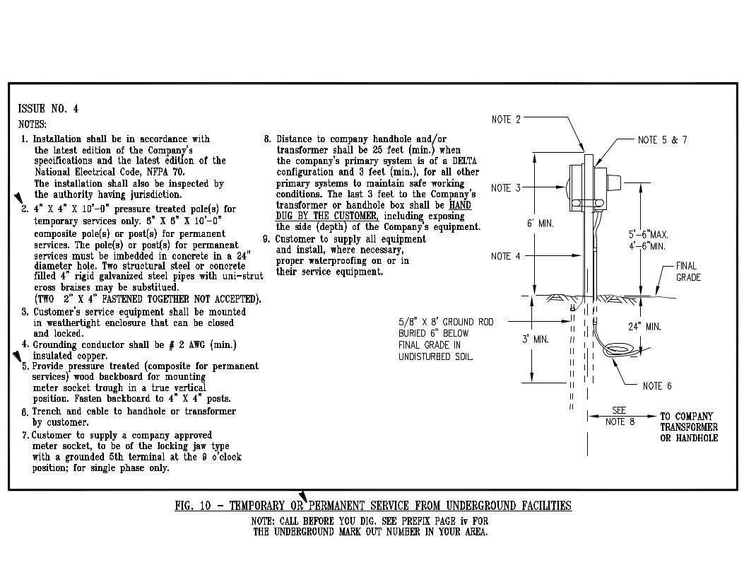
The customer shall provide an adequate support, guyed when necessary, to provide adequate clearance and support for the temporary service conductors. It is the customer's responsibility to supply sufficient length of conductors to reach the Company's designated point of service. For construction of temporary services from overhead facilities, see Fig. 11; from underground facilities see Figure 10. Service entrance, metering equipment, and other wiring on temporary installations are to be installed in the same manner that is required for permanent installations. Approval by the authority having jurisdiction shall be required prior to the Company energizing the customer's service. The Company will prepare a written cost of the installation and removal in those instances where lines, metering, and other necessary equipment are to be installed for the temporary service. The applicant shall pay the Company this cost in advance of construction. The applicant shall be responsible for payment of the energy consumed and applicable demand charges.
E. Inspections. All services must meet the inspection requirements as indicated in Section I, Item 9, prior to being energized by the Company.
F. Access to Customer’s Premises. The Company’s authorized employees or agents
shall have access, at all reasonable times, to its meters and equipment installed on the customer's premises.
6
Section III GENERAL INFORMATION & REQUIREMENTS (cont.) G. Primary Metered Customer’s Equipment. For pole-top primary metering installations:
the customer is responsible for service equipment located beyond the load-side terminals of the metering transformers. For pad-mounted primary metering installations: the customer is responsible for the metering transclosure, the transclosure’s supporting foundation and the service equipment located beyond the load-side of the metering transformers. In both cases, the customer is responsible for the metering cabinet, both procurement and installation.
H. Identification of Employees. Employees of the Company authorized to visit the
customer's premises are furnished with a photo identification card which they will show upon request. This is done to protect customers from unauthorized persons representing themselves as Company employees.
I. Load Balancing. The customer shall balance his/her service load such that each phase
of the service entrance conductors is carrying equal ampacities. J. Unauthorized Attachments to Poles. The Company forbids any unauthorized
attachments such as banners, signs, clotheslines, antennas, basketball hoops, mailboxes, etc., to its poles. It forbids the use of its poles for placards, political posters, articles/equipment for religious purposes or any advertising matter. The Company will remove any such unauthorized attachments without notice and may prosecute such trespass. The Company forbids any work by contractors on its poles or any Company-owned equipment without specific written authorization.
K. Discontinuance of Service. The Company reserves the right to refuse and/or discontinue service to a customer where the National Electrical Code or the Rules of other authoritative agencies, including that of the Company, are violated, or where the customer's equipment or operating methods adversely affects service to other customers. Service will be made available when the violation(s) has been corrected and the appropriate inspections, including by the Company, have been made as per Section I, Item 9.
L. Connections, Service Taps. All connections between Company wires and customer
wires will be made and removed exclusively by Company authorized personnel. The Company reserves the right to make all service connections. Service taps for additional meters SHALL NOT be made in metering equipment enclosures, including instrument transformer cabinets. The connection of the Company’s electric service or any alternative thereof by anyone except Company authorized personnel is PROHIBITED BY THE PENAL LAW AND PUNISHABLE AS A MISDEMEANER, IF DONE WITH THE INTENT TO INJURE OR DEFRAUD. VIOLATORS OF THIS RULE WILL BE PROSECUTED. The law provides that the user of such a connection is presumed to have made or consented to the unauthorized connection and is therefore, punishable as well as the party making the unlawful connection, unless proven to the contrary.
M. Additional Service Taps. There are four approved methods for providing service taps for additional meters:
1. Replacement of existing equipment with Company approved gang metering
equipment.
7
Section III GENERAL INFORMATION & REQUIREMENTS (cont.)
2. Installation of a Company approved sealable/lockable service end box. When
three or more sets of customer’s cables are to be run out of a service end box, the customer must provide and connect service cables to a suitable and permanently attached copper or aluminum buss detail.
3. In an existing sealable/lockable trough. 4. If design allows, double lugging of the line side of a sealable service
switch.
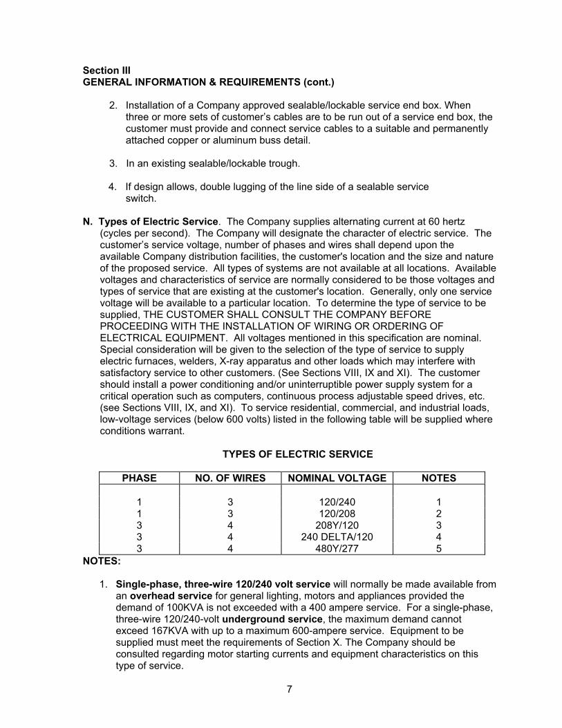
N. Types of Electric Service. The Company supplies alternating current at 60 hertz (cycles per second). The Company will designate the character of electric service. The customer’s service voltage, number of phases and wires shall depend upon the available Company distribution facilities, the customer's location and the size and nature of the proposed service. All types of systems are not available at all locations. Available voltages and characteristics of service are normally considered to be those voltages and types of service that are existing at the customer's location. Generally, only one service voltage will be available to a particular location. To determine the type of service to be supplied, THE CUSTOMER SHALL CONSULT THE COMPANY BEFORE PROCEEDING WITH THE INSTALLATION OF WIRING OR ORDERING OF ELECTRICAL EQUIPMENT. All voltages mentioned in this specification are nominal. Special consideration will be given to the selection of the type of service to supply electric furnaces, welders, X-ray apparatus and other loads which may interfere with satisfactory service to other customers. (See Sections VIII, IX and XI). The customer should install a power conditioning and/or uninterruptible power supply system for a critical operation such as computers, continuous process adjustable speed drives, etc. (see Sections VIII, IX, and XI). To service residential, commercial, and industrial loads, low-voltage services (below 600 volts) listed in the following table will be supplied where conditions warrant.
TYPES OF ELECTRIC SERVICE
PHASE NO. OF WIRES NOMINAL VOLTAGE NOTES
1 3 120/240 1 1 3 120/208 2 3 4 208Y/120 3 3 4 240 DELTA/120 4 3 4 480Y/277 5
NOTES:
1. Single-phase, three-wire 120/240 volt service will normally be made available from an overhead service for general lighting, motors and appliances provided the demand of 100KVA is not exceeded with a 400 ampere service. For a single-phase, three-wire 120/240-volt underground service, the maximum demand cannot exceed 167KVA with up to a maximum 600-ampere service. Equipment to be supplied must meet the requirements of Section X. The Company should be consulted regarding motor starting currents and equipment characteristics on this type of service.

8
Section III GENERAL INFORMATION & REQUIREMENTS (cont.)
2. Single-phase, three-wire 120/208-volt service is restricted to areas where a three-
phase, four-wire, 208Y/120 volt distribution system is available. Loads for this type of service are not to exceed 200 amperes per meter at 120/208 volts. The Company should be consulted regarding the availability of this type of service. THIS TYPE OF SERVICE IS VERY LIMITED. Overhead service drops shall not exceed 400 amperes. Underground service laterals, when fed from an overhead system, shall not exceed 800 amperes. Equipment to be supplied must meet requirements of Section X.
3. Three-phase, four-wire 208Y/120 volt service. This type of service is restricted to customers located in areas where a three-phase, four-wire 208Y/120 volt distribution system may be available, and the load does not exceed a demand of 1000KVA, (2780 amperes at 208 volts). All services over 400 amperes shall be served with an underground service and shall not exceed 800 amperes when served from an overhead system. Demands over 300KVA up to and including 1000KVA shall be served with a three-phase padmount transformer. Lighting and other single-phase loads shall be balanced as closely as practicable among the three phases. Equipment to be supplied must meet the requirements of Section X.
4. Three-phase, four-wire 240 Delta/120-volt service will be made available up to 400 amperes at 240 volts, supplied directly from an overhead supply system only. Services up to 600 amperes at 240 volts shall be served by an underground service lateral and only from an overhead system. This type of service is restricted to commercial and industrial buildings only. Refer to figure 4A for the location of the highest voltage leg in the meter pan.
5. Three-phase, four-wire 480Y/277-volt service. This type of service will be supplied when specifically arranged for and approved by the Company. Lighting and other single-phase loads shall be balanced as closely as practicable among the three phases. All demands over 300KVA shall be served with an underground service. All demands over 500KVA shall be served with a three-phase padmount transformer. All 480-volt meter sockets and metering equipment shall be permanently marked: 480 VOLTS. Labeling shall be located so as to be easily seen by Company personnel. All services over 400 amperes shall be served with an underground service and shall not exceed 600 amperes when served from an overhead system.
6. The maximum number of conductors in any given conduit shall not exceed three conductors for single phase services and four for three phase services.
O. Customer-Owned Generation. The Company shall be consulted in the early planning
stage for the installation of customer owned generation before any electrical equipment is ordered. (See Section XII)

9
Section III GENERAL INFORMATION & REQUIREMENTS (cont.)
P. Swimming Pools. The swimming pool (including any diving structures) and the area
extending 25 feet horizontally from the inside walls of the pool shall not be installed under any existing or proposed overhead wiring. The outside wall of the swimming pool or its auxiliary equipment, shall not be installed closer than five (5) feet from any underground service conductor(s). If lines require relocation, they shall be relocated as quickly as possible to eliminate a potential hazardous condition, the cost of which shall be borne by the customer. Proper clearances shall be maintained as described in the latest editions of the National Electrical Code, NFPA 70, and the National Electrical Safety Code, ANSI C2.
Section IV SERVICE CONNECTIONS A. NUMBER AND ROUTING OF SERVICES
1. The Company will supply only one service of a given type to a building. Exceptions may be made where a customer requires services of different voltage characteristics, large service capacities or construction divided by a fire wall. The customer must obtain prior approval from the Company for any installation of more than one service to a building, The Company reserves the right to review and approve all requests. In the instance where a new customer occupies a building that is currently supplied with a single-phase service, three-phase service or both and it is not of the nominal voltage level that is desired, a customer contribution may be required for the conversion. Where single-phase and three-phase services exist together, the customer shall be required to combine the services into one three-phase service. The type of construction and the routing of the service will be jointly determined by the Company and the customer.
2. The customer, at his/her expense, must obtain and present to the Company for
County recording purposes, satisfactory easements, rights-of-way, permits (except highway permits), consents or certificates necessary to give the Company access to his/her metering/service installation and equipment for the purpose of connecting/energizing the service and for other purposes necessary for the supply of service. Also, the customer, at his/her expense, must secure all permits, municipal and otherwise, required by law for the installation and operation of equipment utilizing the service on his/her premises.
3. The Company shall not be obliged to commence construction of an extension of its
electric system until the applicant or applicants, to be served by such extension have agreed to pay a surcharge or a contribution toward the construction for such costs, as may be incurred by the Company, as stated in the Company's filed tariff, and have:

10
Section IV SERVICE CONNECTIONS (cont.)
a. Obtained and delivered, to the Company, satisfactory permanent easements or rights-of-way agreements; or
b. At the applicant’s request, complete with applicable charges, the Company has obtained such easements or rights-of-way.
4. The Company reserves the right to designate the location of the service point and meter location. The customer is required to contact the Company for pre-approval of the service location. Failure to obtain approval by the Company may result in a customer charge or customer relocating their service. For locations where the customer requires perimeter security (i.e. chain link fence), the overall design must include provisions for Company personnel to access the metering equipment at all times (i.e. dedicated gate access).
NOTE: On all customer installed underground services (0 - 34,500 volts), the customer will be responsible to trench up to the Company’s designated service connection point. The customer or his contractor will machine dig the trench to within three feet (3’) of the Company’s service connection point, i.e.: secondary or primary junction box, transformer or switch foundation, and “hand dig” the last three feet (3’), exposing the Company’s service connection point foundation. When the customer/contractor installs the service in conduit, the conduit shall be stopped three feet (3’) from the bottom flange of the Company’s junction box. The service conductors shall be of length to extend 15 ft. beyond the Company’s service connection point and shall be neatly coiled on top of the ground. The Company will complete the installation. All customers/ contractors shall have the existing below grade utilities located and marked before excavating by calling the appropriate “Call Before You Dig” number, found on prefix page iv.
B. OVERHEAD SERVICE CONNECTIONS BELOW 600 VOLTS
1. The Company will construct and maintain all overhead service drops to the customer's point of attachment. When the line on private property exceeds the allowance as provided in the Company's filed tariff, the customer will be required to contribute to the cost of the installation. NOTE: THE MAXIMUM NUMBER OF WEATHERHEADS ON A BUILDING TO BE SERVED FROM A SERVICE DROP IS TWO (2).
2. On farms or other premises where one or more buildings under one ownership will
be supplied through one meter, it may be an advantage to the customer to install the meter on a customer owned pole and to distribute to the building or buildings directly from this meter pole. If two or more buildings are so served, the customer shall install an overcurrent protective device on the load side of the meter. Also, a temporary meter pole may be desirable for a construction job (see Section III Para. 4) or a customer may desire that the meter be installed on a pole on his property (see Section VII Para. 14). In trailer camps where one or more trailers are to be served from a common point, a pole shall be installed and used as the customer's point of attachment and meter location (see Section XV). In such cases, the meter pole and any necessary guy wires shall be furnished, installed and

11
Section IV SERVICE CONNECTIONS (cont.)
maintained by the customer. In no case shall a meter be installed on a Company-owned or Company-maintained pole. The Company shall be consulted in each case for the Company’s requirements concerning the pole, associated guys and metering requirements for more than one meter and/or building(s), under one ownership, supplied through one meter.
3. The Company will supply (at no cost to the customer) and the customer shall install a
suitable service bracket, together with proper mounting bolts, on an aluminum, vinyl, brick, stone or other masonry building under construction or reconstruction. The Company does not accept responsibility for the structural soundness of the installation.
4. The Company reserves the right to designate the location of the service bracket which normally should be placed on that section of the building closest to the pole from which the service drop will be run. The bracket will be installed on the building at a height of not more than 25 feet nor less than 18 feet above final grade to ensure the following criteria (in accordance with the latest editions of the National Electrical Safety Code, ANSI C2 and the National Electrical Code, NFPA 70, Article 230 - Services.):
10 feet (3.05 m) - at the electric service entrance to buildings, or at the drip loop of the building electric entrance, or above areas or sidewalks accessible only to pedestrians, measured from final grade, or other accessible surface only for service-drop cables supported on and cabled together with a grounded bare messenger and limited to 150 volts to ground.
12 feet (3.66 m) - over residential property where the voltage is limited to 300 volts to ground.
15 feet (4.57 m) - for those areas listed in the 12-foot (3.66 m) classification where the voltage exceeds 300 volts to ground.
18 feet (5.49 m) - over public streets, alleys, roads, all parking areas subject to truck traffic, all driveways including residential and other land such as cultivated, grazing, forest, and orchard traversed by vehicles.
5. Where the customer’s building is too low to permit the installation of the service
bracket at the minimum height of eighteen (18) feet above final grade, the Company shall be consulted. Where local ordinances and field conditions permit, the Company may approve the installation of the service bracket at a lower point provided the minimum clearances specified in the latest edition of the National Electrical Code, NFPA 70, and the National Electrical Safety Code, ANSI C2 can be obtained with the service drop attached at a normal height on the Company's pole.
6. In any case where the building is too low to obtain proper clearances, it is
recommended that the customer install an underground service connection, either to a Company-owned pole or to a customer-owned pole, the location and type approved by the Company, and installed, owned and maintained by the customer on the customer's property. The meter may be set on the latter pole.
12
Section IV SERVICE CONNECTIONS (cont.)
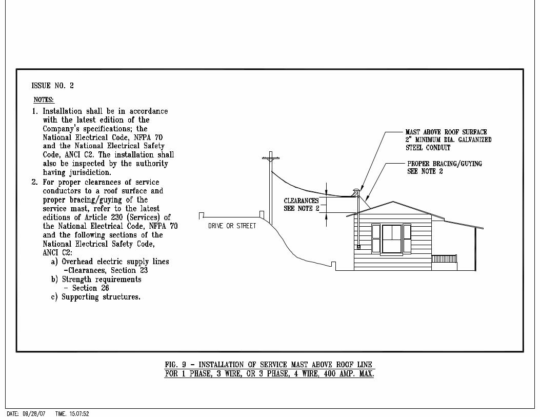
As an alternative, the customer may be required to install a two inch (2”) minimum rigid galvanized steel mast with adequate bracing to provide the proper mounting height for the service bracket (see Figure 9). It is required that the mast be rigid galvanized steel conduit and that the customer's service weatherhead shall be located above and within 12 inches of the point of attachment of the Company's service drop. The installation shall conform to the requirements of the latest edition of the National Electrical Code, NFPA 70, and the National Electrical Safety Code, ANSI C2. In no instance shall the Company attach to a wood mast.
7. All new service entrances installed shall consist of three or more conductors and not
to exceed four (4) conductors per raceway, each phase conductor to have a minimum current carrying capacity of at least 100 amperes for single-phase or three-phase service except as provided for in paragraph 8. To provide for future load growth, the Company recommends that the capacity of service entrance conductors and service equipment be greater than the minimum requirements of the latest edition of the National Electrical Code, NFPA 70.
8. When the service is to be used solely for supplying loads of less than 3,000 watts (30 amperes at 120 volts) in signs or traffic signals, the service entrance may be smaller than 100 amperes as provided by the latest edition of the National Electrical Code, NFPA 70 and upon mutual agreement between the Company and the customer.
9. At least twenty-four (24) inches of each service entrance conductor shall project beyond the service head or termination of the service cable for connection to the Company's service drop.
10. The opening through which the service entrance cable and/or conduit enters the
building must be weatherproofed and/or sealed to prevent the entrance of water. C. UNDERGROUND SERVICE CONNECTIONS BELOW 600 VOLTS
1. It is recommended that an underground service connection be considered wherever the building to be supplied is so low that a "riser” would be required to support the bracket for an overhead service drop. Such underground service connections are especially applicable to one-floor residences where the wall height will not permit the mounting of a service bracket at a height above final grade sufficient to maintain the minimum ground clearances specified in Item 4. The Company's filed tariff is to be consulted concerning the overhead and/or underground extensions of lines and facilities to new residential subdivisions and land development subdivisions.
2. The following tables describe different variations for the installation, ownership and
maintenance of underground service laterals in accordance with the corresponding tariff regulations for each state served by the Company. They apply to all existing and new residential customers located within or outside a subdivision.
13
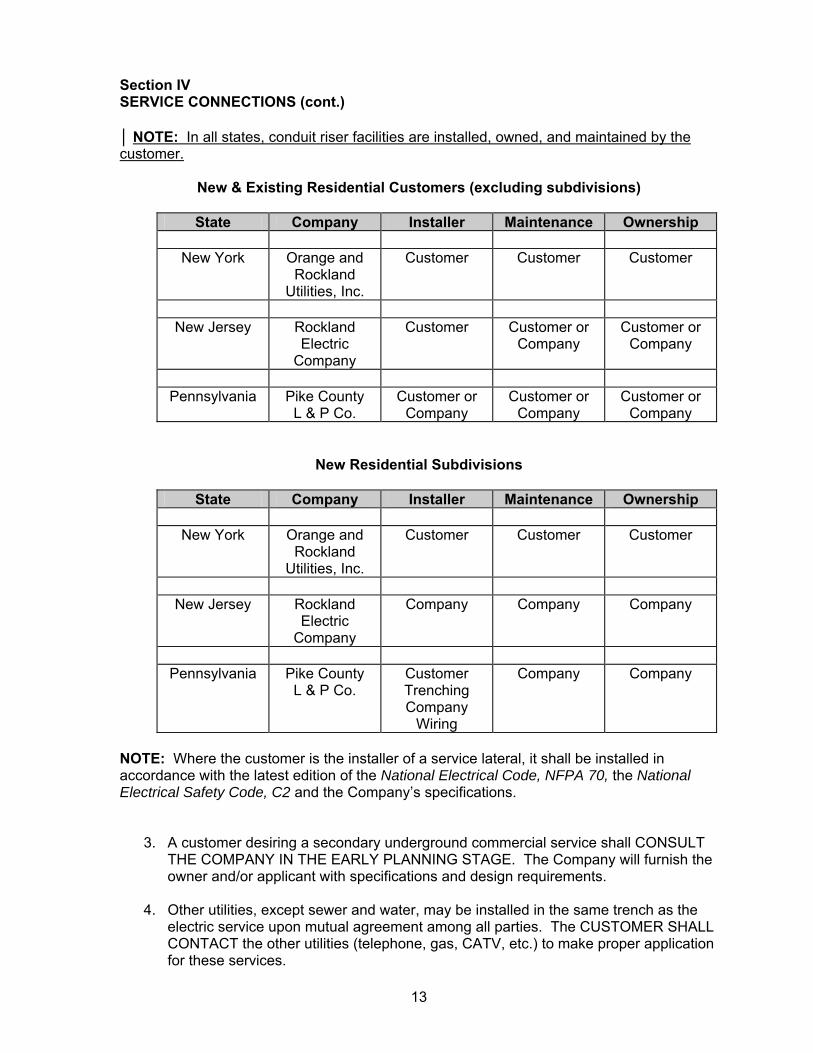
Section IV SERVICE CONNECTIONS (cont.) │ NOTE: In all states, conduit riser facilities are installed, owned, and maintained by the customer.
New & Existing Residential Customers (excluding subdivisions)
State Company Installer Maintenance Ownership
New York Orange and
Rockland Utilities, Inc.
Customer Customer Customer
New Jersey Rockland
Electric Company
Customer Customer or Company
Customer or Company
Pennsylvania Pike County
L & P Co. Customer or
Company Customer or
Company Customer or
Company
New Residential Subdivisions
State Company Installer Maintenance Ownership
New York Orange and Rockland
Utilities, Inc.
Customer Customer Customer
New Jersey Rockland
Electric Company
Company Company Company
Pennsylvania Pike County
L & P Co. Customer Trenching Company
Wiring
Company Company
NOTE: Where the customer is the installer of a service lateral, it shall be installed in accordance with the latest edition of the National Electrical Code, NFPA 70, the National Electrical Safety Code, C2 and the Company’s specifications.
3. A customer desiring a secondary underground commercial service shall CONSULT THE COMPANY IN THE EARLY PLANNING STAGE. The Company will furnish the owner and/or applicant with specifications and design requirements.
4. Other utilities, except sewer and water, may be installed in the same trench as the electric service upon mutual agreement among all parties. The CUSTOMER SHALL CONTACT the other utilities (telephone, gas, CATV, etc.) to make proper application for these services.

14
Section IV SERVICE CONNECTIONS (cont.)
5. The Company reserves the right to designate the location of the meter on the customer’s premises and the point of connection to the Company’s distribution system.
6. All new service entrance conductors shall be Underwriter Laboratories (UL)
approved Type USE, for below grade and above grade installations. The underground service entrance conductors shall consist of a maximum of three (3) conductors per raceway for a single-phase service and a maximum of four (4) conductors per raceway for three-phase services. Each phase conductor shall be sized in accordance with latest edition of the National Electrical Code, NFPA 70. All connections, permanent or temporary, between the Company's electric distribution system and the customer's service lateral conductors shall be made by the Company. The Company will not permit this connection to be made by others.
NOTE 1: Service runs of excessive lengths may require special consideration
such as larger cable due to voltage drop, See Par. 8. NOTE 2: See paragraphs 9 & 14 for riser conduit installation requirements.
7. TRENCHING, BACKFILLING AND PROTECTION. The customer-installed, below-
grade service entrance conductors may be installed in conduit or direct buried and in accordance with the latest editions of the Company’s specifications and the National Electrical Code, NFPA 70, Article 300. In either case, Electrical Caution Tape shall be installed 12 inches below final grade. If the service lateral entrance conductors are installed in conduit(s), the conduit(s) shall have an internal diameter of not less than two inches (2") and shall be one of the following UL approved conduit(s) types:
a. Rigid galvanized steel conduit (RGS), see notes. b. Intermediate metallic conduit (IMC), see notes. c. Schedule 80PVC conduit, see notes. d. Electrical Metallic Tubing, see notes. e. Schedule 40PVC conduit, see notes. NOTE 1: The minimum cover over conduit(s) shall comply with Table 300.5 of
the latest edition of the National Electrical code , NFPA 70. To avoid damage to customer and Company equipment, attention to Sections 300.5, subsection F (backfill) and Section G (ground movement) is required. An expansion joint shall be installed in the raceway riser (on the dwelling) and have the appropriate looping of cable in the metering equipment.
NOTE 2: Only Rigid Galvanized Steel or Sch. 80 PVC is permitted to rise out
of the ground and attach to a pole. NOTE 3: See paragraphs 9 & 14 for riser conduit installation requirements.

15
Section IV SERVICE CONNECTIONS (cont.) The following is applicable to all customer installed direct-buried service lateral cables:
a. The minimum cover over cables shall comply with Table 300.5 of the latest
edition of the National Electrical code , NFPA 70.
b. To protect against ground movement, a minimum of 6” slack of the cables in an “S” configuration shall be made prior to the raceway transition, installation of an expansion joint in the raceway riser (on the dwelling) and have the appropriate looping of cable in the metering equipment.
c. All backfill material shall be clean, free of stones greater than 2” in diameter, cinders and ash. A minimum of 2” cushion of approved sand (Mason or Cement type sand) shall be placed beneath the cables.
8. Length of Underground Services - The customer shall give consideration to the length of service in conjunction with the type of installation - direct buried or in conduit. These distances shall be considered from the Company’s system connection point to the customer’s service point as per the following table:
Service Characteristics * Conductor Size Maximum Length
1Ø 120/240V (200 amp) ** Increase wire size to:
3 wire - 4/0 AWG Al. 350 KCM Al.
250 Ft. *** 460 Ft.
1Ø 120/240V (300 amp) 3 wire - 350 KCM Al. *** 150 Ft. 1Ø 120/240V (400 amp) 3 wire – parallel 4/0 AWG Al. *** 150 Ft. 1Ø 120/240V (600 amp) 3 wire – parallel 350 KCM Al. *** 150 Ft. 3Ø 120/240V, 120/208V or 277/480V (200 amp) ** Increase wire size to:
4 wire - 4/0 AWG Al. 350 KCM AL.
250 Ft. *** 460 Ft.
3Ø 120/240V, 120/208V or 277/480V (300 amp)
4 wire - 350 KCM Al. *** 150 Ft.
3Ø 120/240V, 120/208V or 277/480V (400 amp)
4 wire – parallel 4/0 AWG Al.
*** 150 Ft.
3Ø 120/240V, 120/208V or 277/480V (600 amp)
4 wire – parallel 350 KCM Al.
*** 150 Ft.
3Ø 120/208V or 277/480V (800 amp & larger)
4 wire - sized according to the latest edition of the NEC.
*** 150 Ft.

16
Section IV SERVICE CONNECTIONS (cont.) * Conductor size as stated above or NEC approved conductor equivalent. ** Increase wire size to compensate for voltage loss. *** Services in excess of this length must go with a primary service to a pad mounted transformer on their property. NOTE: All single phase services shall not exceed three (3) conductors per raceway. All three phase services shall not exceed four (4) conductors per raceway.
9. Where the customer's underground service "rises" on a:
a. building exterior surface and is subject to vehicular and mechanical damage, the service conductors shall be installed only in UL approved rigid galvanized steel conduit and grounded as per the latest edition of the National Electrical Code, or Schedule 80 rigid nonmetallic PVC conduit and inspected by the authority having jurisdiction. When the service riser installation is not exposed to mechanical damage, the service conductors may be installed in one of the conduits specified in paragraph 6 above. Also see notes 1 & 2 below.
b. Company distribution system with a DELTA primary circuit voltage (2400 volts or
4800 volts), the customer installed service riser conduit(s) and 90 degree long radius bend(s) shall be UL approved non-metallic rigid Schedule 80 PVC conduit. The Customer is also required to install a UL approved PVC conduit coupling at the top of the conduit riser. Customer installed below grade metallic conduits shall not be closer than twenty-five feet (25') from the base of the pole. Also see notes below.
c. Company distribution pole with a WYE primary circuit voltage (2400/4160 volts or
7620/13200 volts or 19920/34500 volts), the customer installed conduit(s) and 90 degree long radius bend(s) shall be UL approved: Rigid Galvanized Steel and grounded as per the latest edition of the National Electrical Code or Schedule 80 rigid nonmetallic PVC conduit. The Customer is also required to install a UL approved conduit coupling(s) that will connect to The Company's Schedule 40 rigid nonmetallic PVC conduit. Also See Notes below. NOTE 1: The minimum acceptable radius of a below grade two inch (2")
diameter, 90 degree bend at any "rising" location is 24 inches. All riser conduit bends are to be of the long radius sweep design.
NOTE 2: Refer to Para. 13 & 15 for additional riser pole conduit installation
requirements.
10. If the customer’s underground service terminates inside the building, proper watertight and vapor-tight fittings are required at the end of the UL Approved conduit(s). The customer, and not the Company, is responsible to prevent water and vapor ingress to their facility.

17
Section IV SERVICE CONNECTIONS (cont.)
11. When the Company's overhead distribution line is on the same side of the street as
the customer to be served, the customer will install, own and maintain all U.G. facilities as shown in Section XVI, Figure 8.
12. When the Company’s distribution is on the opposite side of the street from the
premises to be served:
a. and where the municipality allows a pole, the Company will extend its overhead facilities to a point located within a right-of-way granted on the customer's premises. The customer shall furnish or obtain, at no expense to the Company, all right-of-way to the service pole, outdoor transformer structure or metering structure on the customer’s premises. The customer shall obtain, complete and return the proper forms from the New Construction Services Field Office. A contribution towards the overhead line extension, if applicable, will be in accordance with the latest edition of the Company’s filed tariff.
b. and where local authority does not allow the installation of an overhead road
crossing, the Company will install and maintain all underground facilities from its overhead distribution system to a Company-designated point on the customer's property. Contribution towards the underground extension, if applicable, will be in accordance with the latest edition of the Company's filed tariff.
Exceptions to a & b above: • In Rockland Electric Company, the Company will install distribution facilities
across the road to the customer’s property line, as per the latest edition of the Company’s filed tariff.
• In Pike County Light and Power Company, the Company will install distribution
facilities across the road to the customer's property line upon receipt of the overhead versus underground cost differential. The customer or contractor will install the service as per the latest edition of the Company's filed tariff.
13. When the customer elects to install his/her own service, the Company will designate
the service connection point. When the installation is designated to be a riser pole, it shall be installed in accordance with the latest editions of the National Electrical Code, NFPA 70; National Electrical Safety Code, ANSI, C2 and the following Company requirements. The service installation to the Company-designated riser pole shall be:
a. Where the Company’s primary voltage distribution system is of a Delta
configuration, the customer shall attach their service lateral conductors, to the base of the pole, in UL approved, Schedule 80 PVC long radius 90 degree sweep(s) and UL approved conduit(s) to a point ten (10’) feet above final ground level.

18
Section IV SERVICE CONNECTIONS (cont.)
b. For the Company’s Grounded WYE primary voltage distribution systems, the
customer shall attach their service lateral conductors, to the base of the pole, in any of the following UL approved long radius 90 degree sweep(s) and UL approved conduit(s) to a point ten (10’) feet above final ground level:
1. Rigid galvanized steel 2. Schedule 80 rigid nonmetallic PVC
c. Rigid Galvanized Steel conduits shall be bonded to the Company installed 5/8” X
8’-0” nominal copper clad ground rod, at the base of the pole, with a #2 AWG copper conductor. The customer is to furnish and install: conduit ground clamp(s), conduit ground wire (minimum #2 AWG copper), for bonding the conduit ground wire to the Company installed 5/8" copper clad ground rod. Note: the Company will connect the Customer's grounding wire to the Company installed ground rod.
In all of the above conduit installations, the customer shall install a UL approved coupling(s) at the top of each conduit. The top of the installed coupling shall be rated for Schedule 40 PVC conduit, for the Company to complete the conduit(s) installation with Schedule 40 nonmetallic PVC conduit(s). The customer’s cables shall be of sufficient length to reach the top of the pole. Pending connection, the cable shall be carefully coiled and fastened to the pole at the top of the conduit taking care not to have less than the minimum bending radius permitted for the cable.
14. A maximum of two (2) electrical conduits, with a maximum size of 4 inches will be permitted on a pole. Each conduit shall not be occupied by more than four (4) conductors. The conductors must be sized according to the latest edition of the National Electrical Code, NFPA 70. See paragraphs 22, 24-B & 24-C for allowable riser conduit(s) materials.
15. All underground services with ampacity ratings of 400 amps and below that are
proposed to be terminated at the Company’s utility poles shall be installed in accordance with the following specifications:
Service Characteristics
*Conductor Size
**Number of conduits approved for
attachment to O&R utility pole.
Number of conductors
permitted per raceway
1Ø 120/240V (200 amp)
3 wire - 4/0 AWG 1 - 2” Conduit Three (3)
3Ø 120/240V, 120/208V or 277/480V
(200 amp)
4 wire - 4/0 AWG 1 - 2” Conduit Four (4)
1Ø 120/240V (300 amp)
3 wire - 350 KCM 1 - 3” Conduit Three (3)
1Ø 120/240V (400 amp)
3 wire - 500 or 600 KCM
1 - 4” Conduit Three (3)
3Ø 120/240V, 120/208V or 277/480V
(400 amp)
4 wire - 500 or 600 KCM
1 - 4” Conduit Four (4)

19
Section IV SERVICE CONNECTIONS (cont.) * Wire sizes per Article 310, “Conductors for General Utility” NEC (NFPA 70), latest
edition. Refer to the latest edition of the NEC for other acceptable conductor ratings.
** Conduit sizes per Appendix C, NEC (NFPA 70) and O&R Specifications for
Electrical Installations, latest editions. Orange and Rockland Utilities will accept 2, 3, and 4 inch conduit. ½ sizes are not approved for use on O&R’s distribution system.
D. OVERHEAD SERVICES 2,400 VOLTS TO 34,500 VOLTS, INCLUSIVE
1. The Company will construct, own and maintain all overhead services up to the designated service connection point for services in the voltage range from 2,400 volts up to and including 34,500 volts.
EXCEPTION: The customer has the right to construct their own pole line providing it’s beyond their primary metering. The Company will supply specifications upon request.
2. The customer shall furnish or obtain, at no expense to the Company, all right-of-way easements from the public right-of-way to the service pole, outdoor transformer structure or metering structure on the customer's premises that may be required by the Company. The customer shall obtain, complete and return the proper forms from the New Construction Services Field Office.
E. UNDERGROUND SERVICES 2,400 VOLTS TO 34,500 VOLTS, INCLUSIVE FROM
OVERHEAD LINES
1. A CUSTOMER DESIRING PRIMARY UNDERGROUND SERVICE SHALL CONSULT THE COMPANY IN THE EARLY PLANNING STAGE. The Company will furnish the customer with specifications and design recommendations to provide primary voltage to the Company's designated service connection point. The labor for the entire underground service installation will be provided by the customer. The customer is encouraged to utilize equipment that meets the Company's material standards/specifications such that emergency material and repairs may be available from the Company.
2. IF THE MUNICIPALITY DOES NOT ALLOW AN OVERHEAD EXTENSION, THEN
THE FOLLOWING PROCEDURES APPLY:
a. Where the Company’s distribution line is on the same side of the street as the customer to be served, the customer will install his/her facilities to the Company’s designated connection point. The service connection point may be at a boxpad/handhole located within a customer granted right-of-way adjacent to the Company’s franchised area. There may be a contribution (aid to construction) based on the Company’s rules and regulations for provisions of electric service as stated in the latest edition of the Company’s filed tariff.
20
Section IV SERVICE CONNECTIONS (cont.)
b. Where the Company’s distribution is on the opposite side of the street from the
customer to be served, the Company will do the following: The Company will install and maintain a boxpad/handhole located on a customer-granted right-of-way (adjacent to our franchise area), an underground road crossing or an underground riser. This work will be done on receipt of a right-of-way and the contribution, if applicable, in accordance with the latest edition of the Company's filed tariff.
3. SERVICE POLE LOCATION: The Company will designate the pole from which
service will be taken and the location of the riser conduit on the pole. Plans of the installation shall be submitted to the Company for approval before construction is started.
4. CONDUIT MATERIAL REQUIREMENTS: Rigid galvanized steel conduit or rigid nonmetallic Schedule 80PVC conduit.
5. CONDUIT/CONDUCTOR SIZES: A conduit of sufficient inside diameter must be
installed to permit the installation of required minimum sized cables. For 15KV, the minimum size conductor(s) is #2 AWG. For 35KV, the minimum size conductor(s) is 1/0 AWG. The following inside diameter of UL approved and Company-approved conduits shall not be less than:
a. Two inches (2”) for one conductor, 15KV construction. b. Four inches (4”) for one conductor, 35KV construction. c. Four inches (4”) for two conductors, 15KV or 35KV construction. d. Four inches (4”) for three conductors, 15KV construction. (See NOTE) e. Six inches (6”) for three conductors, 35KV construction.
NOTE: A larger diameter conduit may be required depending on the specified conductor size and ampacity rating due to customer’s load as required by the Distribution Engineering Department.
6. RISER POLE REQUIREMENTS. Where the customer’s underground service “rises”
on a:
a. Company distribution pole with a DELTA primary circuit voltage (2400 volts or 4800 volts), the customer installed service riser conduit(s) and 90 degree long radius bend(s) shall be 4” UL approved non-metallic rigid Schedule 80 conduit. The Customer is also required to install a UL approved PVC conduit coupling at the top of the conduit riser.
b. Company distribution pole with a WYE primary circuit voltage (2400/4160 volts or
7620/13200 volts or 19920/34500 volts), the customer installed conduit(s) and 90 degree long radius bend(s) shall be UL approved: rigid galvanized steel conduit or Schedule 80 rigid nonmetallic PVC conduit. The Customer is also required to install a UL approved PVC conduit coupling so the Company can complete the installation with PVC conduit on the pole.

21
Section IV SERVICE CONNECTIONS (cont.)
c. In the Company’s Eastern Division - Bergen County, New Jersey, and Rockland
County, New York - the cable shall be rated for 15KV operation. In the Company's Northern Division, the cable shall be rated for 15KV or 35KV operations, as determined by the Company. The Company will furnish, upon request, Company approved specifications for 15KV or 35KV conductors. It is in the customer's best interest to install Company-approved conductors and equipment in case the Company is called upon to restore service due to a customer owned cable failure, restoration time will be minimized.
F. EXCESS FACILITIES
The Company normally provides a single point of attachment of electric service to its distribution line. The Company will consider providing facilities in excess of those it normally allows, subject to the following conditions: 1. Such Excess Facilities will not adversely affect the Company's standard system of
design.
2. Such Excess Facilities will conform with the Company's construction and installation.
3. The utilization of service by the customer through such Excess Facilities will not constitute a present or potential cause of interference with the supply of service to other customers.
4. Such Excess Facilities in no way will jeopardize the health and/or safety of customers of the Company.
5. Such Excess Facilities shall be constructed only after the applicant has made a contribution towards construction in accordance with the Company’s filed tariff.
Section V CUSTOMER’S SERVICE EQUIPMENT A. CUSTOMER’S SERVICE ENTRANCE EQUIPMENT RATED ABOVE 200 AMPERES
AND SERVED AT LESS THAN 600 VOLTS 1. A customer having a load greater than 300 amperes single-phase or 200 amperes
three-phase shall be guided by the following articles in the selection of his service entrance equipment.
Unless required by the latest edition of the National Electrical Code, NFPA 70 or by the Company, the customer’s service equipment must be installed after the metering equipment.

22
Section V CUSTOMER’S SERVICE EQUIPMENT (cont.)
2. The customer shall consult the Company prior to purchasing service equipment,
such as service disconnects and/or main switchgear. The service equipment shall be designed to withstand and interrupt the maximum short-circuit fault current available to the service equipment. In addition, the service equipment’s overcurrent protection scheme shall be compatible with the Company’s system requirements and in accordance with latest edition of the National Electrical Code, NFPA 70.
3. Connections made ahead of the main service equipment for fire pumps, exit lights,
control power for circuit breakers feeding emergency equipment, etc. shall be provided with isolation devices adequate for the duty. Such connections shall:
a. Be made only where specifically approved by the Company.
b. Be made as per the latest edition of the National Electrical Code, NFPA 70.
c. And shall be installed after the meter.
4. Metering: The customer shall provide the required space and mounting facilities for
the Company's meter equipment in accordance with Section VII. B. CUSTOMER’S SERVICE ENTRANCE EQUIPMENT FOR SERVICES ABOVE 600
VOLTS
The customer shall consult the Company in every case where the service voltage may exceed 600 volts. 1. For secondary metered customers: the Company will designate the type of service
based on the location, size and nature of the proposed load and its relation to the Company's facilities. The location of the service equipment and the general electrical arrangement will be agreed upon after mutual consideration of all factors by the customer and the Company. Based on the electrical arrangement selected, the Company will advise the customer concerning its requirements for basic insulation level, protective equipment and metering facilities. The Company will also supply additional information such as estimated short circuit data, relay recommendations, etc. The customer shall submit detailed plans for inspection and approval by the Company prior to the purchase of equipment or proceeding with the installation. The Company will furnish, own, and maintain the meter, the metering transformers and the secondary meter wiring. The customer shall furnish, own and maintain structures and foundations and all other equipment as required.
2. For primary metered customers: the customer's equipment includes primary metering equipment, high voltage disconnecting and overcurrent protective devices, transformer(s) and all high voltage wiring. As per the latest edition of the National Electrical Code, NFPA 70, the customer is required to install a group operating, single throw air isolating switch or an approved equivalent, between the Company’s primary meter and the customer’s transformer(s).

23
Section V CUSTOMER’S SERVICE EQUIPMENT (cont.) C. OUTDOOR TRANSFORMER INSTALLATIONS ON CUSTOMER’S PREMISES
1. For non-residential customers who desire either single-phase or three-phase service from padmounted transformers, refer to the "Specifications for Non-Residential Padmounted Transformer Installations" which will be furnished by the Company after application is submitted to the Company. The customer shall furnish or obtain, at no expense to the Company, all right-of-way easements to gain access to a transformer on the customer's premises that may be required by the Company. The customer shall obtain, complete and return the proper forms to their New Construction Services Field Office.
2. When the Company's transformers are to be located outdoors on the customer's
premises, the customer shall provide the space required and shall consult with the Company regarding the structure and its locations.
3. For secondary metered customers, if the transformers can be supported on one pole which conforms with the Company's construction standards, the Company will furnish, install, own and maintain the equipment including the poles, guys, transformers, fuses, lightning arresters and all associated wiring. The maximum size of pole mounted, three-phase transformer banks that will be installed by Orange and Rockland Utilities, Inc., for a customer's electric service is:
With an OVERHEAD SERVICE DROP, not to exceed 400 amperes (by the Company)
a. 300KVA at 480/277 secondary voltage b. 150KVA at 208/120 secondary voltage c. 150KVA at 240/120 secondary voltage
With an UNDERGROUND SERVICE (by the customer) consisting of not more than two (2) four (4”) inch conduits on the pole
a. 500KVA (600 ampere max. service size) at 480/277 secondary voltage b. 300KVA (800 ampere max. service size) at 208/120 secondary voltage c. 300KVA (600 ampere max. service size) at 240/120 secondary voltage
NOTE: For the low voltage connection from the structure to the customer’s
building or meter pole, see sections entitled “Overhead Service Connections Below 600 Volts” and “Underground Service Connections Below 600 Volts”.
4. Should the customer be required to have the transformer(s) on the ground, the
customer shall provide the foundation(s) for padmounted transformer(s) according to the Company's Specifications for Non-Residential Transformer Installations.
5. In all cases where the customer provides the transformer foundations(s), the design
of the outdoor structure shall be coordinated with the Company before construction is started.

24
Section V CUSTOMER’S SERVICE EQUIPMENT (cont.)
6. The Company will supply, own and maintain the transformer(s) on all secondary
metered installations. The customer will supply, own and maintain the transformer(s) in all primary metered installations. The cost of the high voltage wiring installation, including the associated high voltage disconnecting and overcurrent protective devices required, shall be borne by the customer.
Section VI GROUNDING A. The neutral conductor of each service shall be grounded at the customer's service
entrance equipment in accordance with the latest edition of the National Electrical Code, NFPA 70 and the National Electrical Safety Code, ANSI C2.
B. Special grounding provisions should be utilized where the customer will be using
sensitive electric equipment. See Section VIII, Power Quality. Section VII METERS AND METERING EQUIPMENT A. METERS AND METERING EQUIPMENT BELOW 600 VOLTS
1. GENERAL
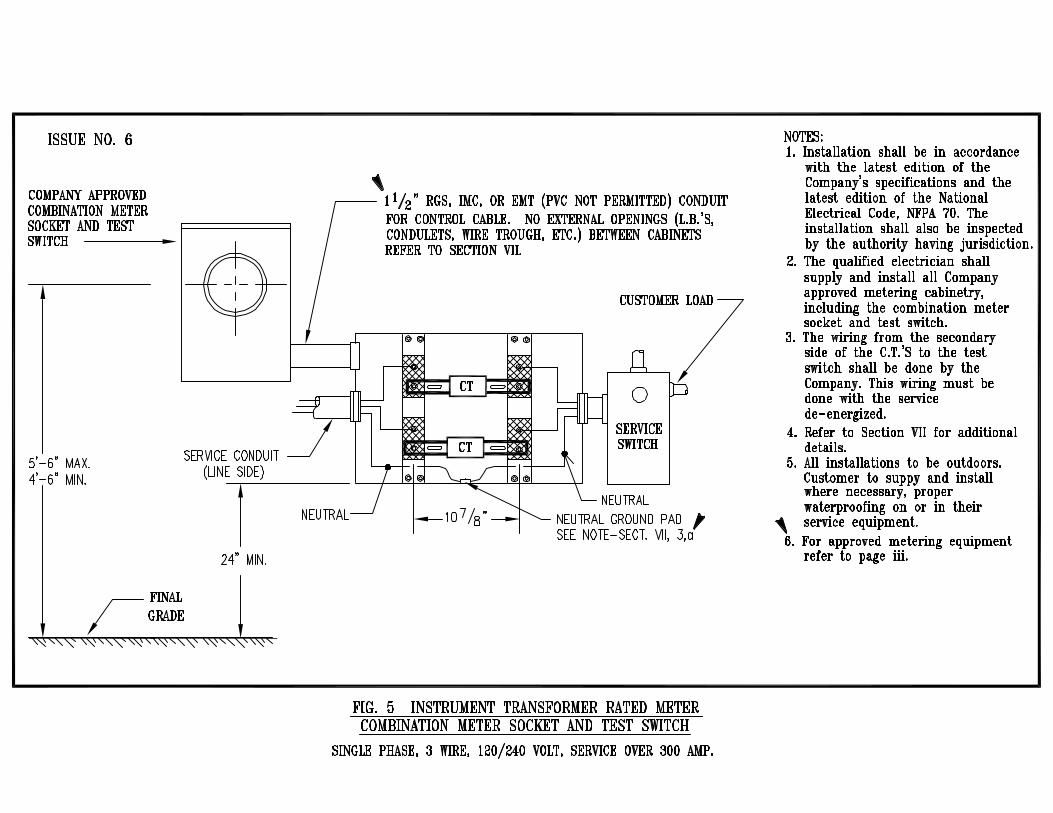
a. The Company will furnish, install and connect all meters required for billing purposes. In addition, the Company will supply, install, and wire all 600 volt class bar-type current transformers and voltage (potential) transformers where required. Window type current transformers and associated voltage (potential) transformers, 600 volt class, and all instrument transformers at higher voltages will be delivered to the jobsite by Company personnel and installed by the customer's qualified electrician. The secondary control wiring and kwh meter installation will be completed by Company personnel.
b. The customer shall furnish, install and maintain all service entrance equipment in
accordance with these specifications. This equipment includes the meter board or panel, switches or circuit breakers, enclosures or mounting facilities for instrument transformers, where required, and conduit for meter cable between all instrument transformers and the meter enclosure or panel. The metallic conduit between the instrument transformer cabinet and the meter enclosure or panel shall have an inside diameter of not less than 1½ inches with no external openings (L.B.s, condulets, wire trough, etc.) between cabinets and the length of conduit MUST NOT exceed 50 feet unless previously approved by a Customer Meter Operations Supervisor. Pull lines shall be provided by the customer whenever the conduit run exceeds ten (10) feet. Flexible conduit is not allowed.
25
Section VII METERS AND METERING EQUIPMENT (cont.)
c. The meter and the instrument transformers will be connected on the line side of the associated switch or circuit breaker as shown on the diagrams at the end of this booklet. Exceptions: Section XVI, Fig. 3. (Fig. 3 is not to be used for 277/480 volt services).
d. All meters, meter facilities and all points of access to un-metered wiring on the
customer’s premises will be sealed by the Company. All cabinets and equipment enclosures containing un-metered conductors shall be made sealable before the service will be energized.
e. All commercial non-transformer rated metering sockets must be on the
Company’s approved list and contain lever bypass capabilities.
f. All three-phase, four-wire services rated at 200 amps or below with self-contained meters at nominal ratings of 240 volts and below shall have Company approved meter sockets with 200 ampere locking type jaw and 200 ampere manually operated lever by-pass switch. For 240/120 volt, three-phase, 4–wire delta installations, the wild phase/red leg (208 volts to ground) shall be mounted on the extreme right side of the meter enclosure. See Section XVI, Figure 4A, Note 7.
g. All services rated at 200 amps or below with self-contained meters at nominal ratings of 277/480 volts shall have Company-approved meter sockets with locking type jaw and 200 ampere manually operated lever bypass switch. A separate non-fusible, sealable, UL approved disconnect device (safety switch or breaker) must be installed on the line side of each meter socket. See Section XVI, Figure 4A. This disconnect is not considered the service disconnect.
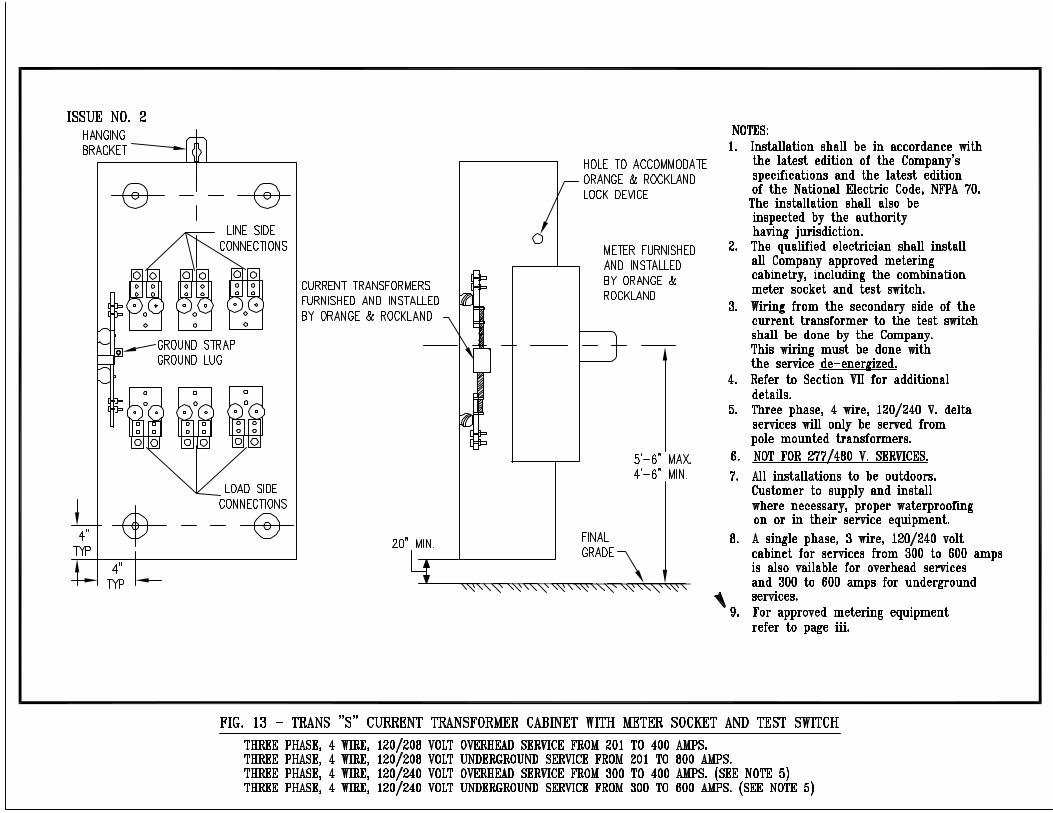
h. All three-phase services rated above 200 amps with transformer rated meters
and a nominal service rating of 240 volts and below will require current transformers and a cabinet. Line and load connections are to be clearly identified and marked. Nominal service ratings of 480 volts will require individual voltage/potential transformers for each meter and a cabinet in addition to the above.
i. All current transformer rated installations must utilize Company-approved current
transformer and voltage (if required) transformer cabinets. An approved Company list of these cabinets can be obtained from your New Construction Services Representative. A current and voltage (if required) transformer installation shall be for the sole use of the customer to be served or being served. Additional services will not be allowed to be taken from a current transformer enclosure. If additional services are required, they must be installed by installing a company approved lockable/sealable service box ahead of all metering equipment.
j. Single-phase, 120/240 volt, 3-wire services rated at 300 amps will require self-
contained meters. No current transformers or cabinet is required. See Section XVI, Figure 4 for details.

26
Section VII METERS AND METERING EQUIPMENT (cont.)
k. The latest list of approved equipment can be obtained from our web site (refer
to page iii for web access) or any NEW CONSTRUCTION SERVICES FIELD OFFICE.
2. METER EQUIPMENT LOCATION
a. The Company will designate the meter location and require transformer
cabinets, meter cabinets and all associated meter installation equipment be on the exterior of building with continuous Company access to facilitate reading and testing. The customer is responsible for maintaining clear access to the metering equipment including installation and trimming of bushes and shrubbery. For outdoor installations, a minimum of 12” clearance is to be maintained between the electric meter and a gas regulator for a gas meter. Switchgear applications on some commercial installations are allowed to be installed indoors with prior Company approval. For indoor installations a minimum of 36” clearance is to be maintained between the electric meter and a gas regulator for a gas meter.
b. All meters shall be installed in an approved meter cabinet or socket enclosure
assembly (pan) and shall be located as close as practicable to a walk or driveway, but not so as to interfere with the free use thereof. The center of the kwh meter shall be 4 ½ to 5 ½ feet above finished grade.
c. All single-phase and network meter installations shall be three wire, at least 100
ampere capacity and equipped for a socket type meter. The meter socket shall contain 5 jaws. The fifth terminal shall be at the 9 o'clock position and is to be grounded. ALL METER INSTALLATIONS SHALL BE OUTDOORS, unless prior approval is given by the Company. Meter sockets for self-contained meters shall be furnished and installed by the customer and shall be Company approved and UL approved. Meter sockets must be installed vertically and plumb using sufficient rust-resistant fasteners to hold the socket securely to the mounting surface, independent of conduit or cable connections. The threads on conduit or service cable fittings shall have joint compound applied to prevent the entrance of moisture or water. The service line side conductors shall be connected to the top terminals of the meter socket and the load side conductors to the bottom terminals. See Section XVI, Figures 1 thru 7. If line side disconnects are required, the above connections shall be adhered to.
d. Where a single-phase, three-wire, 120/240-volt meter, 200 amperes or below, is
to be installed on a customer-owned pole, the meter cabinet shall be mounted to give reasonable protection from damage. The meter socket and service disconnect shall be supported adequately and braced. (See Section XVI, Fig. 2 for details of the installation and recommended grounding practice).

27
Section VII METERS AND METERING EQUIPMENT (cont.)
e. Meters and associated metering equipment shall be grouped together in one location for the premise being served. Meters will not be installed in or on trailers or where subject to vibration or mechanical injury, or on stairways or dangerous locations. In general, meters shall be located so a four foot (4’) minimum clearance will be maintained in front of the metering and entrance equipment and be accessible to Company personnel at all times. Metering equipment shall also be properly protected from dust, moisture, etc., and shall be kept clear of obstructions at all times.
3. GROUNDING OF METER EQUIPMENT ENCLOSURES
Shall be accomplished by installing a metallic conduit between the current transformer cabinet and meter socket/test switch that shall be either 1 ½” RGS (Rigid Galvanized Steel) conduit, IMC (Intermediate Metal Conduit) or EMT (Electric Metallic Tubing) and shall not exceed 50 ft. in length. PVC or flexible conduits, L.B.’s or Condulets are not permitted. If not already installed by the manufacturer, the customers qualified electrician shall install a #10-24 UNC bolt to the neutral bus or neutral block of the current transformer cabinet for the Company’s use.
4. GROUPING OF METERS
a. Where two or more meters are to be installed, they shall be grouped at one
location. Gang metering arrangements for over six (6) meters shall be determined jointly between the customer and the Company. Detailed shop drawings of gang metering arrangements shall be submitted to the New Construction Services Field Office for approval prior to the customer's purchase. A minimum of three (3”) inches of clearance is to be maintained between adjacent meters, meter sockets and other enclosures. A minimum of 12” clearance is to be maintained between the electric meter and a gas regulator or a gas meter.
b. On gang metering, the customer shall "ring-out" and label each meter location
and each individual unit's sub-panel with a permanent legible, stenciled ¾” to 1 ½” in height,, CLEARLY IDENTIFYING THE 9-1-1 ADDRESS TO THE SPECIFIC SPACE OR APARTMENT TO BE SERVED. Such labeling is the customer's responsibility. Labeling is required on each cover and interior of the meter socket and the customer’s electrical panel for each space or apartment.
c. NOTE: IN ORDER TO AVOID MIXED OR SHARED METERING CONDITIONS IN MULTI-UNIT BUILDINGS, UNITS MUST BE IDENTIFIABLE BY COMPLETED FRAMING AND ELECTRICAL ROUGH IN AND MARKED WITH THE FINAL UNIT NUMBER. TO INSURE THE COMPANY’S BILLING ACCURATELY REFLECTS CHARGES FOR THE CUSTOMER’S OWN USAGE, IT IS CRITICAL THAT WIRING BE INSTALLED AND TRACEABLE TO THE DESIGNATED UNIT AND NOTED AS SUCH BY COMPANY PERSONNEL AFTER THE METER INSTALLATION.
28
Section VII METERS AND METERING EQUIPMENT (cont.)
d. Typical gang meter configurations are shown in Section XVI, Figures 2A and 3. Gang metering may be required for multi-family housing; where these arrangements cannot be adapted to meet a particular application, the New Construction Services Field Office shall be consulted before starting the wiring installation.
e. Switchgear and switchboard meter applications may have an instrument
transformer compartment incorporated in its design. New Construction Field Services shall be consulted in regards to the following: 1) the applicability of such metering; 2) transformer compartment space requirements; 3) instructions on transformer installation; and, 4) location of metering equipment.
5. ADDITIONS AND CHANGES TO EXISTING INSTALLATIONS
Where a service entrance is to be replaced, the meter board and equipment shall be rearranged in accordance with the foregoing specifications. Where additions or changes are contemplated in an existing installation, EACH CASE SHALL BE REFERRED TO THE COMPANY BEFORE ELECTRICAL WORK IS BEGUN. Where alterations or additions are being made to existing service installations, all the new work shall be installed in accordance with the latest edition of the National Electrical Code, NFPA 70 and the existing installation shall be changed to conform to this requirement.
6. RELOCATION OF SERVICE ENTRANCE OR METERING EQUIPMENT
Whenever a customer desires to relocate the service entrance and/or metering equipment, he shall first contact the Company for approval of the new locations before installing the new service entrance and metering equipment in accordance with these specifications. The Company will relocate the service lateral and/or service drop as per the Company's filed tariff.
7. SEALS / LOCKING DEVICES
a. All meters and accessible enclosures prior to the Company’s metering point (line side) will be sealed/locked by the Company before the service will be energized. All enclosures used for containing service conductors prior to the Company’s metering point shall have Company-approved sealing/locking provisions. No person except a duly authorized employee of the Company, is permitted to break or replace a seal or to alter or change a meter or its connections or its location.
b. The breaking of seals or the tampering with meters or unmetered wiring by unauthorized persons is prohibited. Attention is called to Section N.Y. 165.15 of the New York Penal Laws; 2620-86(2) of the New Jersey Penal Laws; and Section 3926 - Sub. A, Par. 1 of the Pennsylvania Penal Laws which make such unauthorized tampering a misdemeanor punishable by fine or imprisonment or both.
29
Section VII METERS AND METERING EQUIPMENT (cont.)
8. REVENUE PROTECTION DEVICES
To gain entry to sealed/locked equipment, arrangements are to be made by contacting Customer Service during normal working hours. A minimum of two (2) working days advance notification is required. Electrical contractors will be asked to provide their name and phone number and/or the customer who is requesting the removal.
9. SUB-METERING
For the purpose of private billing of electric consumption, sub-metering is prohibited unless permission is obtained from the Public Utility Commission having jurisdiction.
B. METERS AND METERING EQUIPMENT ABOVE 600 VOLTS 1. The customer shall consult the Company in every case where the service voltage
may exceed 600 volts. The Company will furnish information concerning the metering facilities required.
2. The Company will furnish and install all meters for billing purposes. The Company will also furnish instrument transformers and secondary meter cable where required. The instrument transformers shall not be used to operate customer-owned devices. Only Company-owned equipment will be allowed inside instrument transformer cabinets and/or enclosures. Service taps for additional meters SHALL NOT be made in metering equipment, including instrument transformer cabinets. The customer is responsible for supplying and installing all cabinets.
Section VIII POWER QUALITY A. GENERAL Customers that are proposing to install sensitive electronic equipment or that are
currently operating this equipment in their facilities in various applications should follow the latest power quality methods and include recommendations from power quality consultants for their internal electrical distribution system. Sensitive electronic equipment is commonly used in the controlling and the monitoring of manufacturing processes and in large or medium-sized automatic data processing systems. In addition, various types of "nonlinear" devices such as personal computers, work stations, uninterruptible power supplies or adjustable speed drives are utilized throughout large and small offices. These types of loads could create internal power quality problems. The operating voltage and frequency characteristics of any equipment used in manufacturing processes such as variable speed drives, motors and conveyor systems should be verified with a power quality consultant or the Company before purchasing the equipment for compatibility.

30
Section VIII POWER QUALITY (cont.) B. INSTALLATION REFERENCE AND GUIDELINES
The following publications and guidelines such as the IEEE 1100-1992 (“Recommended Practice for Powering and Grounding Sensitive Electronic Equipment”) (Emerald Book), IEEE 519, (“Recommended Practices and Requirements for Harmonic Control in Electric Power Systems”), the Federal Information Processing Standards (FIPS) Publication 94 and the latest National Electrical Code, NFPA 70, Wiring Systems and Methods for Grounding and Energized Conductors should be adhered to when designing the internal distribution system for new or existing facilities.
C. POWER FACTOR CORRECTION
Customers installing capacitors to improve the power factor of the load should perform power system studies on the entire facility prior to the installation of the capacitors. The Company will provide characteristics of the supply System so that the capacitors may be properly applied and coordinated with the System. It should be noted that capacitors, although they do improve power factor, may detrimentally affect power quality to sensitive equipment.
D. SURGE AND TRANSIENTS PROTECTION DEVICES
Surge protection methods should be followed according to the latest edition of the National Electrical Code, NFPA 70 and be UL listed or equivalent. Service entrance surge protection as well as supplementary surge protection at sensitive equipment should be installed. The customer should consider safeguarding sensitive equipment, using equipment such as solid state line-voltage regulators, transient suppressors, isolation transformers, uninterruptible power supply (UPS) systems or motor generators.
A power quality consultant or the Company should be contacted for further guidance.
Section IX DISTURBANCES A. RADIO AND TELEVISION TRANSMITTERS, FLASHING SIGNS, WELDERS,
ELECTRIC FURNACES The operation of large flashing signs, welders, arc furnaces, dielectric and induction heaters, inverters, variable voltage and frequency devices, radio and television transmitters, X-ray equipment, reciprocating compressors and similar apparatus having intermittent flow of large current sometimes interferes with other users of the electric service. Prior to purchasing any such equipment, the customer shall contact the Company’s New Construction Services Field Office to determine what corrective equipment and other special precautions are required such as not to affect other Company customers (see Section X, Item C).
31
Section X MOTORS AND CONTROLLERS A. GENERAL
The Company shall be consulted concerning the characteristics of the service available to insure that the correct application of both phase and voltage will be applied to the customer's motor installation(s). The correct application of motors is the customer's responsibility. See Section III item 13 of these specifications for the types and sizes of service which may be supplied. The Company shall advise the customer as to the actual voltage characteristics available at their specific location.
B. MOTOR PROTECTION
1. The Company shall be advised before any single-phase of five horsepower or three-phase of 15 horsepower motor or larger is installed by a customer. The information given to the Company shall include the operating characteristics such as: motor size (H.P.), single-phase or three-phase motor, the motor’s operating voltage, full load current, locked rotor current, R.P.M., Hertz, efficiency starting (%), efficiency running (%), power factor starting (%), power factor running (%), NEMA class (type), number of starts per day and if the load of the motor is of a rapidly fluctuating type (for example, sawmill, stone crusher, elevators, etc.)
2. It is recommended that motor starting equipment be so arranged that in the event of
voltage failure, the motor will be disconnected from the line unless it is equipped for automatic starting after such a failure. Also, motors should be properly protected against overload. It is the customer's responsibility to protect a motor against operation at any ampere level which exceeds its rating.
Where the continuous operation of motorized equipment is critical, motor controls should be provided (where conditions permit) which will allow motors to operate through zero voltage for a period up to ½ second. The customer should consult the Company where problems of this nature may be encountered.
3. Three-phase service is susceptible to a phenomenon known as single phasing due
to the interruption of one or two phases of the three-phase supply. This may be caused by a number of factors in the utility system or the customer's wiring, including but not limited to single-phase to ground faults, wires down due to storms, vehicular pole accidents, blown fuses, etc. Three-phase customers may receive sustained low voltage on one or two phases until normal service can be restored. The customer's equipment shall have suitable protection against single phasing.

32
Section X MOTORS AND CONTROLLERS (cont.)
C. MOTOR STARTING REQUIREMENTS
1. UNIFORM VOLTAGE IS IMPORTANT IN MAINTAINING SATISFACTORY SERVICE TO ALL CUSTOMERS
Objectionable voltage variations may result from operating electrical equipment such as motors, welders, furnaces, etc., especially during the start-up period. The severity and frequency of the disturbance is a measure of its objectionable effect, not only on the customer causing the disturbance, but also on other customers. Customers shall not operate equipment which produces severe and/or frequent voltage disturbances and should consult with the Company if there is any likelihood that such equipment may be in its operation (see Section IX).
2. To protect the Company’s service voltage characteristics, it is necessary to set a maximum permissible limit to the current drawn from the customer’s service during each step of a motor starting operation. The fluctuations in the current drawn by the motor during normal running conditions shall not exceed this maximum permissible limit as defined in Item D, this section, or as furnished by the Company.
3. THE SPECIFIC MOTOR STARTING CURRENT LIMITATION STATED in the motor
starting current rules (see item D) or furnished by the Company means the maximum allowable increase in current on the line side of the motor starting device at any instant during the starting operation. The limitation does not restrict the total current that can be taken by the motor in starting but may require that the total be built up gradually or in steps, each of which does not exceed the specific limitation for the motor. Where a step type starter is used, an appreciable time must be allowed on each step.
4. WHEN MOTORS ARE STARTED IN A GROUP INSTEAD OF INDIVIDUALLY, the
starting current limitations apply to the group and not to the individual motors. D. MOTOR STARTING CURRENT RULES
The motor starting current rules in this section state the conditions under which single-phase and three-phase motors may be started. The following motor starting current rules are based on "locked rotor" current values at rated voltage. The rules are applicable to combined light and power current, from secondary systems.
Not more than four (4) starts per hour are permitted with long periods of continuous operation under maximum load conditions. Consult the Company where these conditions cannot be met, or where equipment rating and/or starting characteristics exceed the values in the tables below.
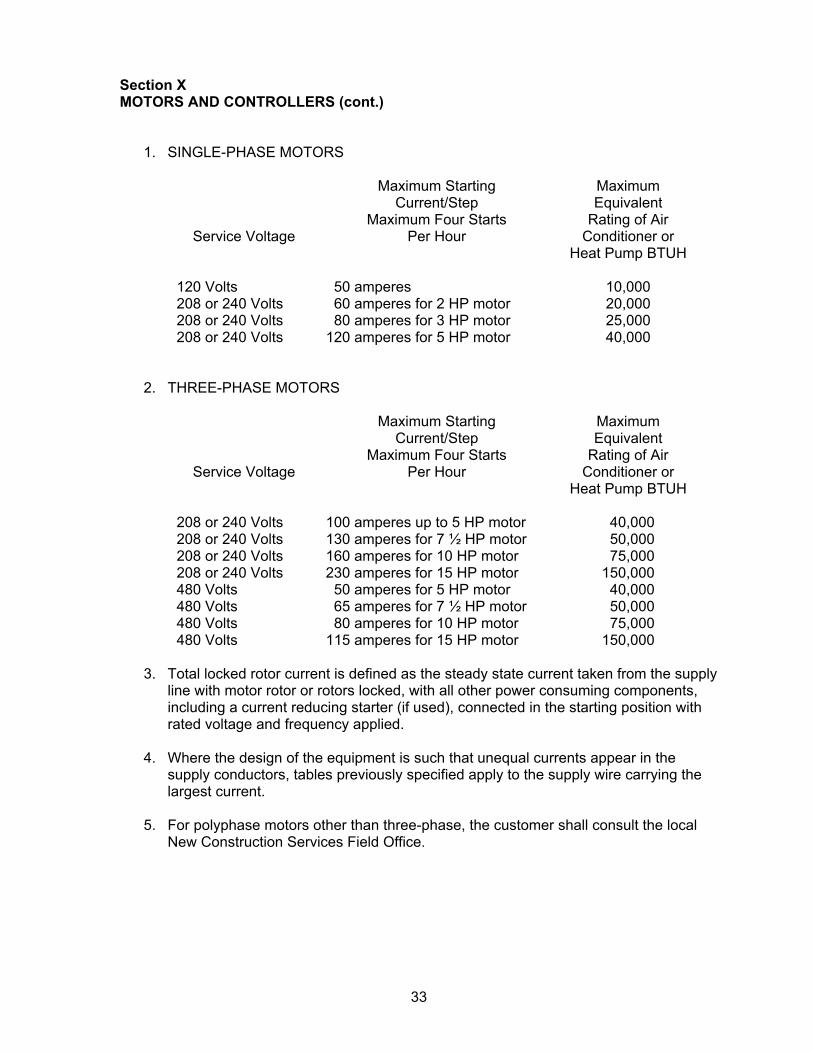
33
Section X MOTORS AND CONTROLLERS (cont.)
1. SINGLE-PHASE MOTORS
Service Voltage
Maximum Starting Current/Step
Maximum Four Starts Per Hour
Maximum Equivalent
Rating of Air Conditioner or
Heat Pump BTUH 120 Volts 50 amperes 10,000 208 or 240 Volts 60 amperes for 2 HP motor 20,000 208 or 240 Volts 80 amperes for 3 HP motor 25,000 208 or 240 Volts 120 amperes for 5 HP motor 40,000
2. THREE-PHASE MOTORS
Service Voltage
Maximum Starting Current/Step
Maximum Four Starts Per Hour
Maximum Equivalent
Rating of Air Conditioner or
Heat Pump BTUH 208 or 240 Volts 100 amperes up to 5 HP motor 40,000 208 or 240 Volts 130 amperes for 7 ½ HP motor 50,000 208 or 240 Volts 160 amperes for 10 HP motor 75,000 208 or 240 Volts 230 amperes for 15 HP motor 150,000 480 Volts 50 amperes for 5 HP motor 40,000 480 Volts 65 amperes for 7 ½ HP motor 50,000 480 Volts 80 amperes for 10 HP motor 75,000 480 Volts 115 amperes for 15 HP motor 150,000
3. Total locked rotor current is defined as the steady state current taken from the supply
line with motor rotor or rotors locked, with all other power consuming components, including a current reducing starter (if used), connected in the starting position with rated voltage and frequency applied.
4. Where the design of the equipment is such that unequal currents appear in the supply conductors, tables previously specified apply to the supply wire carrying the largest current.
5. For polyphase motors other than three-phase, the customer shall consult the local New Construction Services Field Office.
34
Section XI GENERATING EQUIPMENT A. GENERAL
1. The Company shall be consulted in the early planning stage of the generation proposal before any equipment is purchased, whether for paralleling or standby generation. Any electric power producing equipment such as solar-electric panels, fuel cells, windmills, micro-turbines, etc., even if it has an inverter based utility interface, is considered generating equipment.
2. Any expense incurred by the Company to provide interconnection to the customer
shall be the responsibility of the customer.
3. All installations of a customer's generating equipment shall require adherence to fundamental rules for the safeguarding of all personnel and the Company's equipment. The installation must be in accordance with the latest editions of the Company’s specifications, National Electrical Code, NFPA 70; National Electrical Safety Code, C2; IEEE 1547 and be inspected and approved by the Company.
B. STANDBY GENERATION
1. In situations where generating equipment is strictly utilized for backup or standby purposes, it shall be 60 Hertz alternating current and it shall operate so it is ISOLATED from the COMPANY'S ELECTRIC SYSTEM THROUGH A DOUBLE THROW SWITCH. This switch, whether automatic or manual, must be approved by the Company.
2. COMPANY REPRESENTATIVES FROM NEW CONSTRUCTION SERVICES AND
DISTRIBUTION ENGINEERING MUST APPROVE THE DESIGN AND INTERFACE EQUIPMENT TO BE INSTALLED.
C. PARALLEL OPERATIONS
Interconnection REQUIREMENT SPECIFICATIONS are provided separately from these specifications by the Company for various generation levels. These requirements must be adhered to and verified by the Distribution Engineering Department before any designs and agreements are completed.
All customer's or Company's equipment necessary to meet these requirement specifications are to be at the cost of the customer.
D. DISTRIBUTION CIRCUIT INTERCONNECTION
Customer’s generator facility will be connected to the nearest existing distribution circuit. The cost to upgrade the distribution system interconnection to the appropriate voltage level indicated by the Company will be the responsibility of the customer.
A single customer will be limited to a maximum of 5.0MW of generation from one Company distribution circuit.

35
Section XI GENERATING EQUIPMENT (cont.) E. TRANSMISSION LINE INTERCONNECTION
Customer generation that is greater than 5.0MW will be connected to the nearest transmission line or substation. Any transmission line extension or system upgrade required to reach the interconnection point will be at the cost of the customer. All disconnect devices, automatic or manual, shall have a solid neutral connection.
All installations must be inspected and approved by the Company and must comply with the latest edition of the National Electrical Code, NFPA 70 and the National Electrical Safety Code, C2.
Section XII TRANSFORMER INSTALLATION ON CUSTOMER’S PREMISES A. GENERAL
A customer or group of customers on one property may be served from a Company transformer. In such instances, the Company will require that its transformer(s) and other line equipment be installed on the customer's property. The customer shall provide suitable space, foundations or pads, and conduit as required by the Company. The Company shall have the right of access to this space at all times and the right of inspection up to and including the first protective device on the customer's system. The customer may be required to supply a suitable easement.
B. ARRANGEMENTS
1. The type of transformer installation will depend upon specific conditions. The customer shall, in all cases, consult the Company regarding the location, selection and details of the transformer prior to finalizing plans.
2. The general arrangement for installation of the Company's transformers are:
a) Pole mounted b) Padmounted
NOTE: Existing pole-type transformer services, in a vault or fence- enclosed pad
or on an elevated platform, requiring service modifications will be required to install a padmounted transformer.
3. As conditions warrant, refer to the following Company publication:
“Specifications for Residential and Non-Residential Padmounted Transformer Installations”.

36
Section XIII MOBILE HOMES, MOBILE HOME PARKS AND RECREATIONAL VEHICLE PARKS A. MOBILE HOME: DEFINITION
A mobile home is a factory assembled structure or structures equipped with the necessary service connections and made so as to be readily movable as a unit or units on their own running gear and designed to be used as a dwelling unit(s) without a permanent foundation.
B. SERVICE
1. The requirements for electric service and meters for mobile homes and mobile home parks must be given special consideration (Refer to Figure 2 or 2A if applicable). The Company shall be consulted in advance regarding each specific installation.
2. When the service is overhead, the customer shall be required to provide a Class
Seven or better, 30 foot pressure treated pole and an anchor guy, when necessary, adjacent to but not attached to the mobile home for attachment of the service drop.
3. The service entrance conductors for a single meter or multiple meters shall be sized
in accordance with the latest edition of the National Electrical Code, NFPA 70 for a single meter position.
4. The customer shall provide an approved meter socket and mounting panel for the
support of the Company's meters. Where the service entrance conductors are underground, the meter may be located on an approved service pedestal. Contact the New Construction Services Field Office for approval of the pedestal prior to purchase.
5. The customer's service equipment shall be suitable for connection to a supply
system nominally rated at 120/240 volts, 3 wire AC, single-phase with a grounded neutral.
6. The grounding shall be in accordance with the latest edition of the National Electrical
Code, NFPA 70 and Company standards. C. RECREATIONAL VEHICLE: DEFINITION
A recreational vehicle is a unit primarily designed as temporary living quarters for recreational, camping or travel use, which either has its own motive power or is mounted on or drawn by another vehicle. The basic entities are: travel trailer, camping trailer, truck camper and motor home.
D. RECREATIONAL VEHICLE PARKS: DEFINITION
Recreational Vehicle Park is an accommodation for recreational vehicles where individual site occupancy is normally of short duration.

37
Section XIII MOBILE HOMES, MOBILE HOME PARKS AND RECREATIONAL VEHICLE PARKS (cont.)
E. SERVICE
Service to a recreational vehicle park will be provided through one service lateral and/or drop and one or more meters at one location in the name of the park operator. The service equipment and meter(s) shall be at the same location. INDIVIDUAL VEHICLE SITES SHALL NOT BE METERED AS PER THE COMPANY'S FILED TARIFF.
Section XIV INDEX TO DIAGRAMS A. Outdoor Installations. Self-Contained Meters. FIGURE Meter Socket Mounting Devices. Single-Phase and Network: --One Meter. (Service 200 Amps or Less) 1 --One Meter On A Pole. (Service 200 Amps or Less) 2 --Ganged Metering 3 --One Meter. (Service 300 Amps Only) 4 Meter Socket Mounting Devices. Three-Phase, One Meter.
(Service 200 amps maximum):
--4 wire, 120/208 volt 4A --4 wire, 120/240 volt 4A --4 wire, 277/480 volt 4A B. Mobile Homes and Trailer Courts 2A C. Outdoor Installations. Instrument Transformer Rated Meters Combination Meter Socket and Test Switch Mounting Devices: --Single-Phase. One Meter (Service Over 300 Amps) 5 --Three-Phase. One Meter (Refer to Fig. for Service Size) --4 Wire, 120/208 Volt 6 --4 Wire, 120/240 Volt 6 --4 Wire, 277/480 Volt 7 Trans “S” Cabinets Three Phase 4 Wire: --120/208 Volt Overhead Service From 201 to 400 Amps. 13 --120/208 Volt Underground Service From 201 to 800 Amps. 13 --120/240 Volt Overhead Service From 300 to 400 Amps. 13 --120/240 Volt Underground Service From 300 to 600 Amps. 13 D. Typical Underground Service Connection Below 600 Volts From Overhead Line 8 E. Installation of Service Mast Above Roof Line For Single-Phase, 3-wire, 120/240
Or Three-Phase, 4-Wire, 400 Amp. Max. 9 F. Temporary or Permanent Services From Underground Facilities 10 G. Temporary Services from Overhead Facilities 11 H. Service Definitions 12