General Purpose Fuses IEC - Sahabat Mitra · General Purpose Fuses IEC General Purpose Fuses IEC...
97
General Purpose Fuses IEC General Purpose Fuses IEC
Transcript of General Purpose Fuses IEC - Sahabat Mitra · General Purpose Fuses IEC General Purpose Fuses IEC...

General Purpose Fuses IECGeneral Purpose Fuses IEC

GPEU2
Ferrule Fuses aM & gG 400V to 690V
with/without StrikeraM & gG 8x32, 10x38, 14x51, 22x58
General Purpose Fuses IECGeneral Purpose Fuses IEC
Residential and IndustrialCylindrical Fuse-links
Ferraz Shawmut gF/gG-gG and aM fuse-links covera wide range of physical sizes and ampere ratingsfor 250, 380*/ 400, 500, and 660* 690volts AC.
gF/gG fuse-links are for residential use. gG and aMfuse-links are for industrial applications. Most
ratings are available with an optional indicator. Allindustrial fuse-links have the option of a built-in
striker. All cylindrical fuse-links have ceramic bodiesand silver-plated ferrules.
* Fuse-links marked 380V (gF/gG) and 660V (gG-aM) will be
re-marked (and safely used at ) 400V AC and 690V AC in
compliance with changes in IEC Standard 269, but should
not be used above 418V AC or 726V AC.
gF/gG
ResidentialFull RangeProtection
• 7 physical sizesfrom 6.3 x 23mmto 10.3 x 38 mm
• 250 and 380 Volt ratings - 0.5A through 32A
• Most ratingsavailable withindicator
• Meet IEC, NFC,UNE standards
• See residentialfuse-links, SpecialPurpose section
gG
Full RangeProtection
• 4 physical sizes from 8 x 31mmto 22 x 58 mm
• 400, 500 and 690 Volt ratings -0.5Athrough 125A
• Most ratingsavailable withindicator
• Meet IEC, NFCand UNEstandards
• Approved byLloyds Registerof Shipping andBureau Veritas
gG
Full RangeProtection
Fuse-links with striker
• 2 sizes-14 x 51mmand 22 x 58 mm
• 400, 500 and690 Volt ratings4A through 125A
• All ratingsinclude striker
• Meet IEC,NFC and UNEstandards
• Approved byLloyds Register ofShipping and Bureau Veritas
aM
Short CircuitProtection
Fuse-links with striker
• 2 sizes - 14 x 51mm and22 x 58mm
• 400, 500 and690 Volt ratings- 2A through125A
• All ratingsinclude striker
• Meet IEC, NFCand UNE standards
• Approved byLloyds Registerof Shipping andBureau Veritas
aM
Short CircuitProtection
• 4 physical sizesfrom 8 x 31 mmto 22 x 58 mm
• 400, 500 and690 Volt ratings-0.16A through125A
• Most ratingsavailable withindicator
• Meet IEC, NFCand UNEstandards
• Approved byLloyds Registerof Shipping and Bureau Veritas
GPEU3
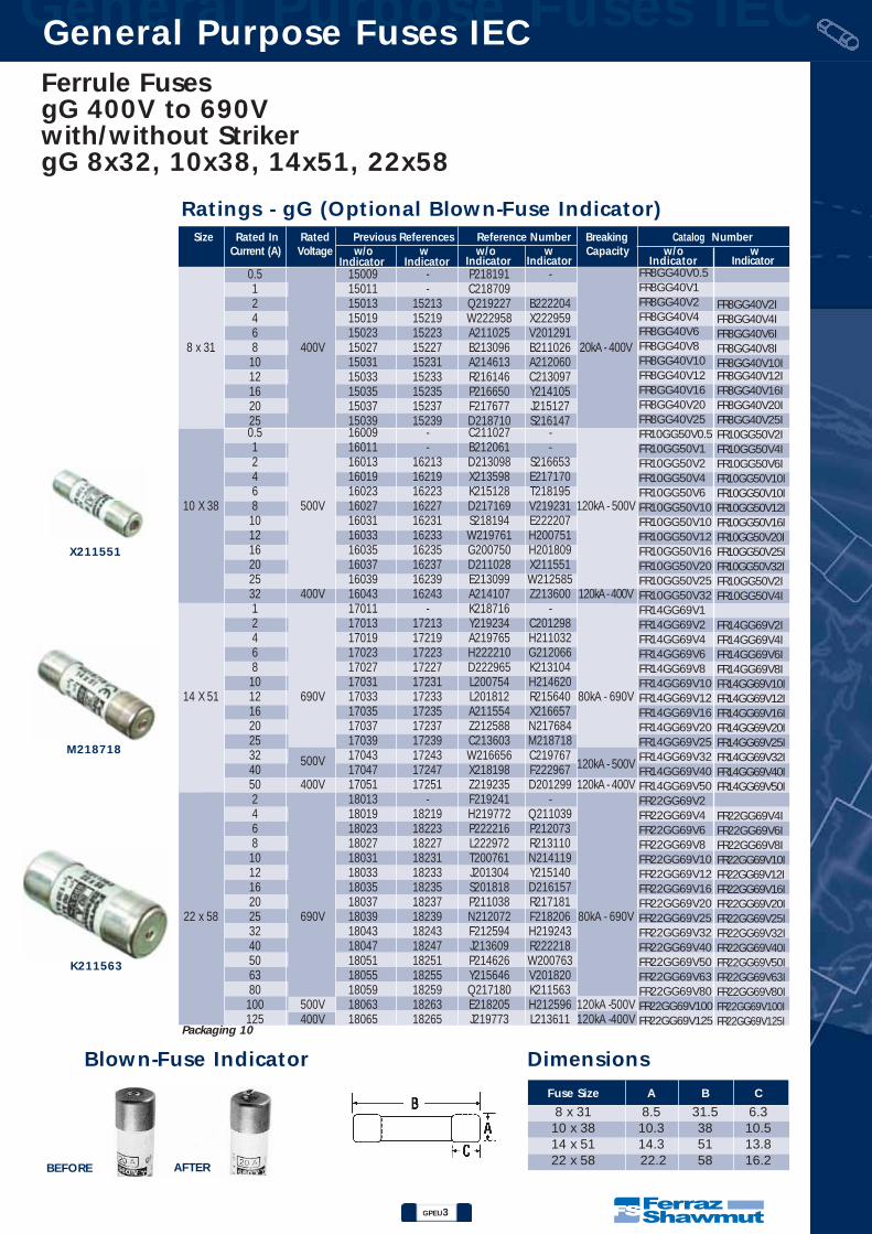
General Purpose Fuses IECGeneral Purpose Fuses IECFerrule Fuses gG 400V to 690Vwith/without StrikergG 8x32, 10x38, 14x51, 22x58
Size Rated In Rated Previous References Reference Number Breaking Catalog NumberCurrent (A) Voltage w/o w w/o w Capacity w/o w
0.5 15009 - P218191 -1 15011 - C2187092 15013 15213 Q219227 B2222044 15019 15219 W222958 X2229596 15023 15223 A211025 V201291
8 x 31 8 400V 15027 15227 B213096 B211026 20kA - 400V10 15031 15231 A214613 A21206012 15033 15233 R216146 C21309716 15035 15235 P216650 Y21410520 15037 15237 F217677 J21512725 15039 15239 D218710 S2161470.5 16009 - C211027 -1 16011 - B212061 -2 16013 16213 D213098 S2166534 16019 16219 X213598 E2171706 16023 16223 K215128 T218195
10 X 38 8 500V 16027 16227 D217169 V219231 120kA - 500V10 16031 16231 S218194 E22220712 16033 16233 W219761 H20075116 16035 16235 G200750 H20180920 16037 16237 D211028 X21155125 16039 16239 E213099 W21258532 400V 16043 16243 A214107 Z213600 120kA - 400V1 17011 - K218716 -2 17013 17213 Y219234 C2012984 17019 17219 A219765 H2110326 17023 17223 H222210 G2120668 17027 17227 D222965 K21310410 17031 17231 L200754 H214620
14 X 51 12 690V 17033 17233 L201812 R215640 80kA - 690V16 17035 17235 A211554 X21665720 17037 17237 Z212588 N21768425 17039 17239 C213603 M21871832 17043 17243 W216656 C219767
120kA - 500V40500V
17047 17247 X218198 F22296750 400V 17051 17251 Z219235 D201299 120kA - 400V2 18013 - F219241 -4 18019 18219 H219772 Q2110396 18023 18223 P222216 P2120738 18027 18227 L222972 R21311010 18031 18231 T200761 N21411912 18033 18233 J201304 Y21514016 18035 18235 S201818 D21615720 18037 18237 P211038 R217181
22 x 58 25 690V 18039 18239 N212072 F218206 80kA - 690V32 18043 18243 F212594 H21924340 18047 18247 J213609 R22221850 18051 18251 P214626 W20076363 18055 18255 Y215646 V20182080 18059 18259 Q217180 K211563100 500V 18063 18263 E218205 H212596 120kA -500V125 400V 18065 18265 J219773 L213611 120kA -400V
Fuse Size A B C
8 x 31 8.5 31.5 6.310 x 38 10.3 38 10.514 x 51 14.3 51 13.822 x 58 22.2 58 16.2
Dimensions
K211563
X211551
M218718
Ratings - gG (Optional Blown-Fuse Indicator)
Blown-Fuse Indicator
AFTERBEFORE
Indicator Indicator Indicator Indicator Indicator Indicator
Packaging 10
FR8GG40V0.5FR8GG40V1FR8GG40V2FR8GG40V4FR8GG40V6FR8GG40V8FR8GG40V10FR8GG40V12FR8GG40V16FR8GG40V20FR8GG40V25FR10GG50V0.5FR10GG50V1FR10GG50V2FR10GG50V4FR10GG50V6FR10GG50V10FR10GG50V10FR10GG50V12FR10GG50V16FR10GG50V20FR10GG50V25FR10GG50V32FR14GG69V1FR14GG69V2FR14GG69V4FR14GG69V6FR14GG69V8FR14GG69V10FR14GG69V12FR14GG69V16FR14GG69V20FR14GG69V25FR14GG69V32FR14GG69V40FR14GG69V50FR22GG69V2FR22GG69V4FR22GG69V6FR22GG69V8FR22GG69V10FR22GG69V12FR22GG69V16FR22GG69V20FR22GG69V25FR22GG69V32FR22GG69V40FR22GG69V50FR22GG69V63FR22GG69V80FR22GG69V100FR22GG69V125
FR8GG40V2IFR8GG40V4IFR8GG40V6IFR8GG40V8IFR8GG40V10IFR8GG40V12IFR8GG40V16IFR8GG40V20IFR8GG40V25IFR10GG50V2IFR10GG50V4IFR10GG50V6IFR10GG50V10IFR10GG50V10IFR10GG50V12IFR10GG50V16IFR10GG50V20IFR10GG50V25IFR10GG50V32IFR10GG50V2IFR10GG50V4I
FR14GG69V2IFR14GG69V4IFR14GG69V6IFR14GG69V8IFR14GG69V10IFR14GG69V12IFR14GG69V16IFR14GG69V20IFR14GG69V25IFR14GG69V32IFR14GG69V40IFR14GG69V50I
FR22GG69V4IFR22GG69V6IFR22GG69V8IFR22GG69V10IFR22GG69V12IFR22GG69V16IFR22GG69V20IFR22GG69V25IFR22GG69V32IFR22GG69V40IFR22GG69V50IFR22GG69V63IFR22GG69V80IFR22GG69V100IFR22GG69V125I
GPEU4
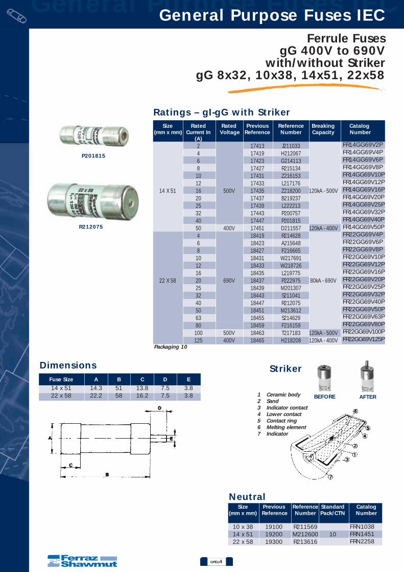
Ferrule Fuses gG 400V to 690V
with/without StrikergG 8x32, 10x38, 14x51, 22x58
General Purpose Fuses IECGeneral Purpose Fuses IEC
P201815
R212075
Size Rated Rated Previous Reference Breaking Catalog(mm x mm) Current In Voltage Reference Number Capacity Number
(A)2 17413 J2110334 17419 H2120676 17423 G2141138 17427 R215134
10 17431 Z21615312 17433 L217176
14 X 51 16 500V 17435 Z218200 120kA - 500V20 17437 B21923725 17439 L22221332 17443 P20075740 17447 P20181550 400V 17451 D211557 120kA - 400V4 18419 R2146286 18423 A2156488 18427 F216665
10 18431 W21769112 18433 W21872616 18435 L219775
22 X 58 20 690V 18437 P222975 80kA - 690V25 18439 M20130732 18443 S21104140 18447 R21207550 18451 M21361263 18455 S21462980 18459 F216159
100 500V 18463 T217183 120kA - 500V125 400V 18465 H218208 120kA - 400V
Ratings – gI-gG with Striker
Fuse Size A B C D E
14 x 51 14.3 51 13.8 7.5 3.822 x 58 22.2 58 16.2 7.5 3.8
Dimensions
1 Ceramic body2 Sand3 Indicator contact4 Lower contact5 Contact ring6 Melting element7 Indicator
Striker
BEFORE AFTER
Size Previous Reference Standard Catalog(mm x mm) Reference Number Pack/CTN Number
10 x 38 19100 R21156914 x 51 19200 M212600 1022 x 58 19300 R213616
Packaging 10
Neutral
FR14GG69V2PFR14GG69V4PFR14GG69V6PFR14GG69V8PFR14GG69V10PFR14GG69V12PFR14GG69V16PFR14GG69V20PFR14GG69V25PFR14GG69V32PFR14GG69V40PFR14GG69V50PFR22GG69V4PFR22GG69V6PFR22GG69V8PFR22GG69V10PFR22GG69V12PFR22GG69V16PFR22GG69V20PFR22GG69V25PFR22GG69V32PFR22GG69V40PFR22GG69V50PFR22GG69V63PFR22GG69V80PFR22GG69V100PFR22GG69V125P
FRN1038FRN1451FRN2258
GPEU5
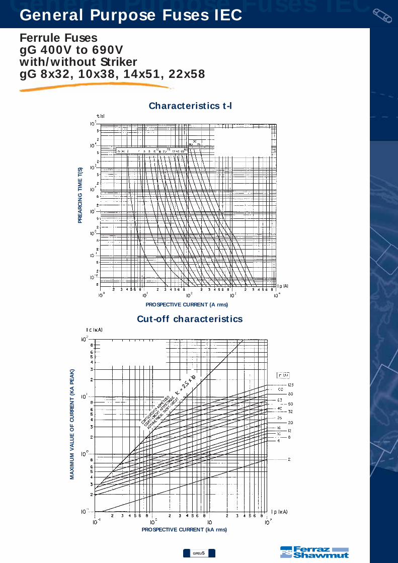
Ferrule Fuses gG 400V to 690Vwith/without StrikergG 8x32, 10x38, 14x51, 22x58
General Purpose Fuses IECGeneral Purpose Fuses IEC
Characteristics t-l
Cut-off characteristics
PREA
RC
ING
TIM
E T
(S)
PROSPECTIVE CURRENT (A rms)
PROSPECTIVE CURRENT (kA rms)
MA
XIM
UM
VA
LUE O
F C
URREN
T (K
A P
EA
K)

GPEU6
General Purpose Fuses IECGeneral Purpose Fuses IEC
Characteristics I2t
Table temperature increase (testing in superior contact)ºC
100
90
80
70
60
50
40
30
20
10
2 4 6 8 10 12 16 20 25 32 2 4 6 8 10 12 16 20 25 32 40 50 16 20 25 32 40 50 63 80 100 125 In10 x 38 14 x 51 22 x 58
690 V
500 V
400 V}{
- OPERATING I2T
- PREARCING I2T
gG
86543
2
86543
2
86543
2
86543
2
86543
2
2
Ferrule Fuses gG 400V to 690V
with/without StrikergG 8x32, 10x38, 14x51, 22x58

GPEU7
General Purpose Fuses IECGeneral Purpose Fuses IEC
Table of maximum length of network in function of In and conductor section.Maximum standardized power low.
Maximum standardized power low.
* 99/118: - 99; Cond. PVC / 118; Cond. PRC
0,5 A
1 A
2 A
4 A
6 A
8 A
10 A
12 A
16 A
20 A
25 A
32 A
40 A
50 A
63 A
80 A
100 A
125 A
2 W
2,5 W
0,70 W
0,80 W
0,90 W
1,10 W
1,35 W
1,55 W
1,90 W
2,30 W
2,80 W
3 W
3,4 W
1 W
1,10 W
1,20 W
1,50 W
1,80 W
2,10 W
2,55 W
3 W
3,50 W
3,80 W
4,40 W
4,7 W
1,20 W
1,30 W
1,40 W
1,65 W
2 W
2,40 W
3 W
3,40 W
3,80 W
4,30 W
5,10 W
5,50 W
6,70 W
8 W
9 W
12,5 W
In10 x 38 14 x 51 22 x 58
Size
IEC 269-2-1NFC 63.213
UNE 21.103-2-1
10 x 38
25 A
3 W
14 x 51
40 A
5 W
22 x 58
100 A
9,5 W
1,52,546
1016253550
16
99/11320
86/87134
25
40/59110/122
183
32
21/2967/84139214
40
13/1641/51
108/119165275
50
7/925/3367/84139226
63
13/2046/58
94/113172283
80
8/1124/3255/70130217336
100
14/1733/41
90/108168257367
125
7,3/1020/2757/70128197283379
Copper conductorsection (mm2)
Rated Current (In) OF gG Fuses (in A)
gG Class Fuses
Power loss table
Ferrule Fuses gG 400V to 690Vwith/without StrikergG 8x32, 10x38, 14x51, 22x58

General Purpose Fuses IECGeneral Purpose Fuses IEC
S219229
F214618
Q217686
C215650
FUSE SIZE A B C
8 x 31 8.5 31.5 6.310 x 38 10.3 38 10.514 x 51 14.3 51 13.822 x 58 22.2 58 16.2
DimensionsBlown-Fuse Indicator
Size Rated In Rated Previous Reference Reference Number Breaking Catalog Number
(mm x mm) Current (A) Voltage w/o w w/o w Capacity w/o w1
15511 - C217168 -2 15513 - R218193 -4 15519 - S219229 -
8 x 31 6 400V 15523 - C222205 - 20kA - 400V8 15527 - F200749 -
10 15531 - W201292 -0.16 16503 - E214617 -0.25 16507 - M215130 -0.5 16509 - W216150 -1 16511 16711 F217171 X2192332 16513 16713 H218714 G2222094 16519 16719 W219232 K2007536 16523 16723 F222208 K201811
10 X 38 8 500V 16527 16727 Z201295 Z211553 120kA - 500V10 16531 16731 Y211552 H21310212 16533 16733 A213601 D21411016 16535 16735 F214618 P21513220 16537 16737 X216151 V21665525 400V 16539 16739 G217172 L217682 120kA - 400V32 400V 16543 - J218715 - 120kA - 400V
0.25 17507 - B212590 -0.5 17509 - L213105 -1 17511 17711 E213605 C2125912 17513 17713 H214114 M2131064 17519 17719 K214622 J2141156 17523 17723 S215135 T2151368 17527 17727 T215642 A216660
10 17531 17731 Z216659 R21768714 X 51 12 690V 17533 17733 M217177 Q218721 80kA - 690V
16 17535 17735 Q217686 F21977020 17537 17737 P218720 R20075925 17539 17739 E219769 Q20181632 17543 17743 M222214 F211559 120kA - 500V40 500V 17547 17747 Q200758 D21259245 17549 17749 L211035 G21360750 400V 17551 17751 E211558 M214624 120kA - 400V1 18511 - M219776 -2 18513 - T222220 -4 18519 18719 Q222976 L2192466 18523 18723 Y200765 V2222218 18527 18727 N201308 Y201823
10 18531 18731 X201822 N21156612 18533 18731 T211042 K21259816 18535 18735 M211565 P213614
22 x 58 20 690V 18537 18737 S212076 V214631 80kA - 690V25 18539 18739 J212597 D21565132 18543 18743 V213113 J21666840 18547 18747 N213613 Z21769450 18551 18751 R214122 P21977863 18555 18755 C215650 Z20076680 18559 18759 H216667 P211567
100 500V 18563 18763 Y217693 L212599 120kA - 500V125 400V 18565 18765 J218209 W214632 120kA - 400V
Ferrule Fuses aM 400V to 690V
with/without StrikeraM 8x32, 10x38, 14x51, 22x58
Ratings – aM (Optional Blown-Fuse Indicator)
BEFORE AFTER
Indicator Indicator Indicator Indicator Indicator Indicator
Packaging 10
FR8AM40V1FR8AM40V2FR8AM40V4FR8AM40V6FR8AM40V8FR8AM40V10FR10AM50V0.16FR10AM50V0.25FR10AM50V0.5FR10AM50V1FR10AM50V2FR10AM50V4FR10AM50V6FR10AM50V10FR10AM50V10FR10AM50V12FR10AM50V16FR10AM50V20FR10AM50V25FR10AM50V32FR14AM69V0.25FR14AM69V0.5FR14AM69V1FR14AM69V2FR14AM69V4FR14AM69V6FR14AM69V8FR14AM69V10FR14AM69V12FR14AM69V16FR14AM69V20FR14AM69V25FR14AM69V32FR14AM69V40FR14AM69V45FR14AM69V50FR22AM69V1FR22AM69V2FR22AM69V4FR22AM69V6FR22AM69V8FR22AM69V10FR22AM69V12FR22AM69V16FR22AM69V20FR22AM69V25FR22AM69V32FR22AM69V40FR22AM69V50FR22AM69V63FR22AM69V80FR22AM69V100FR22AM69V125
FR10AM50V1IFR10AM50V2IFR10AM50V4IFR10AM50V6IFR10AM50V10IFR10AM50V10IFR10AM50V12IFR10AM50V16IFR10AM50V20IFR10AM50V25I
FR14AM69V1IFR14AM69V2IFR14AM69V4IFR14AM69V6IFR14AM69V8IFR14AM69V10IFR14AM69V12IFR14AM69V16IFR14AM69V20IFR14AM69V25IFR14AM69V32IFR14AM69V40IFR14AM69V45IFR14AM69V50I
FR22AM69V4IFR22AM69V6IFR22AM69V8IFR22AM69V10IFR22AM69V12IFR22AM69V16IFR22AM69V20IFR22AM69V25IFR22AM69V32IFR22AM69V40IFR22AM69V50IFR22AM69V63IFR22AM69V80IFR22AM69V100IFR22AM69V125I
GPEC8

GPEU9
General Purpose Fuses IECGeneral Purpose Fuses IEC
X215645
K216669
Fuse Size A B C D E
14 x 51 14.3 51 13.8 7.5 3.822 x 58 22.2 58 16.2 7.5 3.8
Size Rated Rated Previous Reference Breaking Catalog(mm x mm) Current In Voltage Reference Number Capacity Number.
(A)
1 17911 W2156442 17913 B2166614 17919 C2182036 17923 E2192408 17927 N222215
10 17931 S20076014 X 51 12 500V 17933 R201817 120kA 500V
16 17935 G21156020 17937 E21259325 17939 H21360832 17943 N21462540 17947 X21564545 17949 C21666250 400V 17951 D218204 120kA - 400V1 18911 E2156522 18913 J2161624 18919 A2176956 18923 Y2187288 18927 Q219779
10 18931 S22297812 18933 R20131116 18935 W211044
22 X 58 20 690V 18937 W212079 80kA - 690V25 18939 Q21361532 18943 X21463340 18947 F21565350 18951 K21666963 18955 B21769680 500V 18959 Z218729 120kA - 500V
100 18963 T222979125 400V 18965 S201312 120kA - 400V
Dimensions
Ratings – aM with Striker
Striker
BEFORE AFTER
Ferrule Fuses aM 400V to 690Vwith/without StrikeraM 8x32, 10x38, 14x51, 22x58
Packaging 10
Size Previous Reference Standard Catalog(mm x mm) Reference Number Pack/CTN Number
10 x 38 19100 R21156914 x 51 19200 M212600 1022 x 58 19300 R213616
Neutral
FR14AM69V1PFR14AM69V2PFR14AM69V4PFR14AM69V6PFR14AM69V8P
FR14AM69V10PFR14AM69V12PFR14AM69V16PFR14AM69V20PFR14AM69V25PFR14AM69V32PFR14AM69V40PFR14AM69V45PFR14AM69V50PFR22AM69V1PFR22AM69V2PFR22AM69V4PFR22AM69V6PFR22AM69V8P
FR22AM69V10PFR22AM69V12PFR22AM69V16PFR22AM69V20PFR22AM69V25PFR22AM69V32PFR22AM69V40PFR22AM69V50PFR22AM69V63PFR22AM69V80P
FR22AM69V100PFR22AM69V125P
FRN1038FRN1451FRN2258

GPEU10
General Purpose Fuses IECGeneral Purpose Fuses IEC
Characteristics t-lPREA
RC
ING
TIM
E T
(S)
PROSPECTIVE CURRENT (A rms)
PROSPECTIVE CURRENT (kA rms)
Cut-off characteristics
MA
XIM
UM
VA
LUE O
F C
URREN
T (K
A P
EA
K)
aM
Ferrule Fuses aM 400V to 690V
with/without StrikeraM 8x32, 10x38, 14x51, 22x58

GPEU11
General Purpose Fuses IECGeneral Purpose Fuses IEC
Characteristics I2t
Temperature increase table (testing in superior contact)ºC
80
70
60
50
40
30
20
10
1 2 4 6 8 10 12 16 20 25 32 1 2 4 6 8 10 12 16 20 25 32 40 50 1 2 4 6 8 10 12 16 20 25 32 40 50 In10012563 80
10 x 38 14 x 51 22 x 58
690 V
500 V
400 V}{
- OPERATING I2T
- PREARCING I2T
RATED CURRENT (A)
I2T
VA
LUE (
A2S) aM
Ferrule Fuses gG 400V to 690Vwith/without StrikeraM 8x32, 10x38, 14x51, 22x58

GPEU12
General Purpose Fuses IECGeneral Purpose Fuses IEC
0,16 A
0,25 A
0,5 A
1 A
2 A
4 A
6 A
8 A
10 A
12 A
16 A
20 A
25 A
32 A
40 A
45 A
50 A
63 A
80 A
100 A
125 A
0,35 W
0,50 W
0,50 W
0,13 W
0,20 W
0,30 W
0,45 W
0,55 W
0,65 W
0,75 W
0,90 W
1,10 W
1,40 W
2 W
0,70 W
0,75 W
0,18 W
0,25 W
0,40 W
0,55 W
0,65 W
0,75 W
0,85 W
1,20 W
1,50 W
1,80 W
2,10 W
2,60 W
2,80 W
2,90 W
0,20 W
0,30 W
0,50 W
0,65 W
0,75 W
0,85 W
1 W
1,40 W
1,70 W
2 W
2,60 W
3,20 W
3,90 W
4,60 W
5,60 W
6,50 W
9,50 W
In10 x 38 14 x 51 22 x 58
Size
IEC 269-2-1NFC 63.213
UNE 21.103-2-1
10 x 38
16 A
1,2 W
14 x 51
50 A
3 W
22 x 58
100 A
7 W
Table of maximum length of network in function of In and conductor section.Maximum standardized power low.
Power loss table
1,52,546
10162535
16
55/64116181273
20
37/4584/94147223
25
25/3058/68118178
32
15/2040/4984/95139227
40
26/3258/68
105/117181
50
17/2042/4879/89147236
63
28/3355/64
113/125189
80
18/2337/4280/94151231
100
26/3157/69120185262
125
14/2040/4783/97147210
Copperconductor
section (mm2)
Rated Current (In) OF aM Fuses (in A)
aM Class Fuses
Ferrule Fuses aM 400V to 690V
with/without StrikeraM 8x32, 10x38, 14x51, 22x58
Maximum standardized power low.

NH Fuses (Plain Blades)gG 400V, 500V, 690V aM 500V, 690V
GPEU13
General Purpose IEC Fuses General Purpose IEC Fuses
NH Fuse System
DIN 57 636/VDE 0636 Parts 1, 10, 21, 22, 201
IEC 60269-2
DIN 43 620 Parts 1 to 4 (Standard dimensions)
The use category is identified by two letters, the first indicating theoperational class and the second the object to be protected. The Ferraz shawmut range includes fuse-links to DIN VDE 0636standard for the following uses categories:
gG: general purpose cable and line protectionaM: Partial purpose, motor circuit protectiongTr: general purpose, transformer protectiongR: general purpose, fast actingaR: partial purpose, fast acting
Classification
The NH system is classed among plug-in fuse systems and is comprised of:- fuse-base, (possibly including terminal covers and phase barriers)- fuse-link with blade contact- fuse-link replacement device (LV HRC fuse puller)
Since the design of this system cannot guarantee non-interchangeability of rated current, it must behandled by a qualified professional.
Approval symbols
Germany
Austria
Netherlands
~0% lead
~0% cadmium
~it costs you not a pennymore !
~it corresponds with the2nd design of Europeanelectronical scrapsguideline
~100% for a sure future
Switzerland
General Purpose IEC Fuses General Purpose IEC Fuses
GPEU14
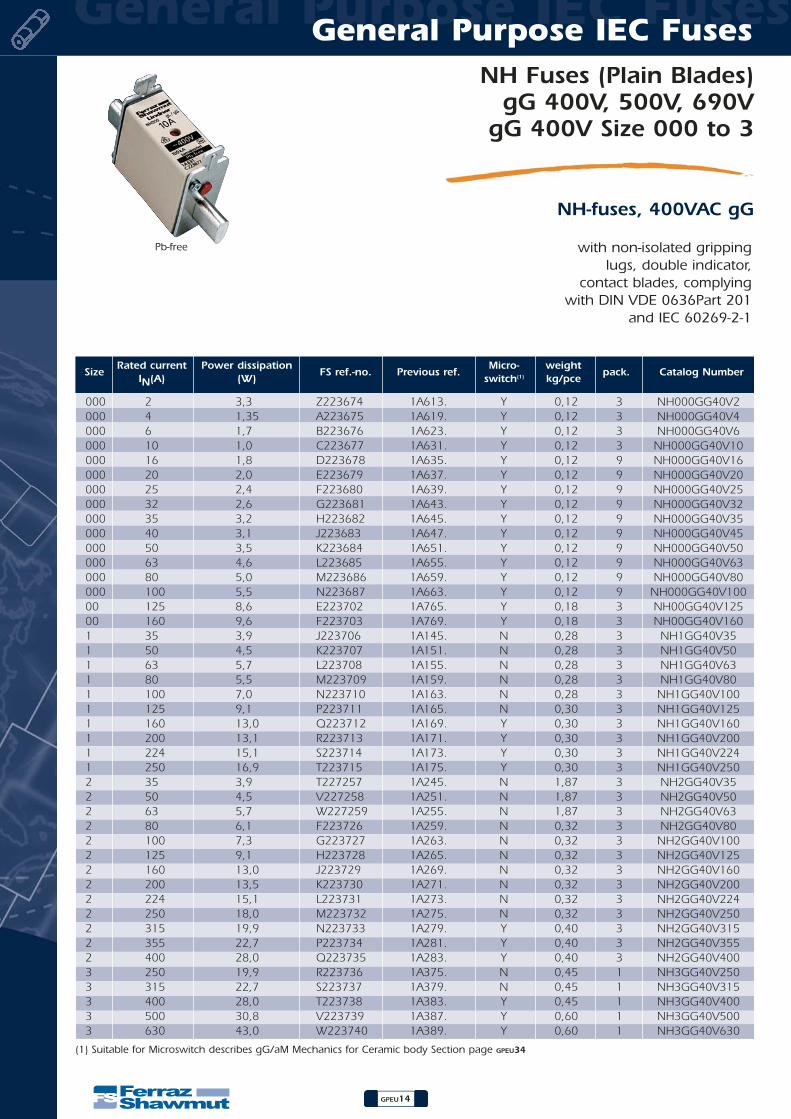
NH Fuses (Plain Blades)gG 400V, 500V, 690V
gG 400V Size 000 to 3
NH-fuses, 400VAC gG
with non-isolated grippinglugs, double indicator,
contact blades, complyingwith DIN VDE 0636Part 201
and IEC 60269-2-1
Pb-free
SizeRated current Power dissipation
FS ref.-no. Previous ref.Micro- weight
pack. Catalog NumberIN(A) (W) switch(1) kg/pce
000 2 3,3 Z223674 1A613. Y 0,12 3000 4 1,35 A223675 1A619. Y 0,12 3000 6 1,7 B223676 1A623. Y 0,12 3000 10 1,0 C223677 1A631. Y 0,12 3000 16 1,8 D223678 1A635. Y 0,12 9000 20 2,0 E223679 1A637. Y 0,12 9000 25 2,4 F223680 1A639. Y 0,12 9000 32 2,6 G223681 1A643. Y 0,12 9000 35 3,2 H223682 1A645. Y 0,12 9000 40 3,1 J223683 1A647. Y 0,12 9000 50 3,5 K223684 1A651. Y 0,12 9000 63 4,6 L223685 1A655. Y 0,12 9000 80 5,0 M223686 1A659. Y 0,12 9000 100 5,5 N223687 1A663. Y 0,12 900 125 8,6 E223702 1A765. Y 0,18 300 160 9,6 F223703 1A769. Y 0,18 31 35 3,9 J223706 1A145. N 0,28 31 50 4,5 K223707 1A151. N 0,28 31 63 5,7 L223708 1A155. N 0,28 31 80 5,5 M223709 1A159. N 0,28 31 100 7,0 N223710 1A163. N 0,28 31 125 9,1 P223711 1A165. N 0,30 31 160 13,0 Q223712 1A169. Y 0,30 31 200 13,1 R223713 1A171. Y 0,30 31 224 15,1 S223714 1A173. Y 0,30 31 250 16,9 T223715 1A175. Y 0,30 32 35 3,9 T227257 1A245. N 1,87 32 50 4,5 V227258 1A251. N 1,87 32 63 5,7 W227259 1A255. N 1,87 32 80 6,1 F223726 1A259. N 0,32 32 100 7,3 G223727 1A263. N 0,32 32 125 9,1 H223728 1A265. N 0,32 32 160 13,0 J223729 1A269. N 0,32 32 200 13,5 K223730 1A271. N 0,32 32 224 15,1 L223731 1A273. N 0,32 32 250 18,0 M223732 1A275. N 0,32 32 315 19,9 N223733 1A279. Y 0,40 32 355 22,7 P223734 1A281. Y 0,40 32 400 28,0 Q223735 1A283. Y 0,40 33 250 19,9 R223736 1A375. N 0,45 13 315 22,7 S223737 1A379. N 0,45 13 400 28,0 T223738 1A383. Y 0,45 13 500 30,8 V223739 1A387. Y 0,60 13 630 43,0 W223740 1A389. Y 0,60 1
(1) Suitable for Microswitch describes gG/aM Mechanics for Ceramic body Section page GPEU34
NH000GG40V2NH000GG40V4NH000GG40V6
NH000GG40V10NH000GG40V16NH000GG40V20NH000GG40V25NH000GG40V32NH000GG40V35NH000GG40V45NH000GG40V50NH000GG40V63NH000GG40V80
NH000GG40V100NH00GG40V125NH00GG40V160
NH1GG40V35NH1GG40V50NH1GG40V63NH1GG40V80
NH1GG40V100NH1GG40V125NH1GG40V160NH1GG40V200NH1GG40V224NH1GG40V250NH2GG40V35NH2GG40V50NH2GG40V63NH2GG40V80
NH2GG40V100NH2GG40V125NH2GG40V160NH2GG40V200NH2GG40V224NH2GG40V250NH2GG40V315NH2GG40V355NH2GG40V400NH3GG40V250NH3GG40V315NH3GG40V400NH3GG40V500NH3GG40V630
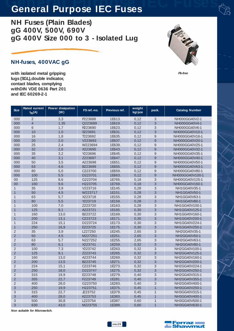
NH Fuses (Plain Blades)gG 400V, 500V, 690V gG 400V Size 000 to 3 - Isolated Lug
GPEU15
General Purpose IEC Fuses General Purpose IEC Fuses
NH-fuses, 400VAC gG
with isolated metal grippinglugs (SGL),double indicator,contact blades, complyingwithDIN VDE 0636 Part 201and IEC 60269-2-1
Pb-free
Non suitable for Microswitch.
SizeRated current Power dissipation
FS ref.-no. Previous ref.weight
pack. Catalog NumberIN(A) (W) kg/pce
000 2 3,3 P223688 1E613. 0,12 3000 4 1,35 Q223689 1E619. 0,12 3000 6 1,7 R223690 1E623. 0,12 3000 10 1,0 S223691 1E631. 0,12 3000 16 1,8 T223692 1E635. 0,12 9000 20 2,0 V223693 1E637. 0,12 9000 25 2,4 W223694 1E639. 0,12 9000 32 2,6 X223695 1E643. 0,12 9000 35 3,2 Y223696 1E645. 0,12 9000 40 3,1 Z223697 1E647. 0,12 9000 50 3,5 A223698 1E651. 0,12 9000 63 4,6 B223699 1E655. 0,12 9000 80 5,0 C223700 1E659. 0,12 9000 100 5,5 D223701 1E663. 0,12 900 125 8,6 G223704 1E765. 0,18 300 160 9,6 H223705 1E769. 0,18 31 35 3,9 V223716 1E145. 0,28 31 50 4,5 W223717 1E151. 0,28 31 63 5,7 X223718 1E155. 0,28 31 80 5,5 Y223719 1E159. 0,28 31 100 7,0 Z223720 1E163. 0,28 31 125 9,1 A223721 1E165. 0,30 31 160 13,0 B223722 1E169. 0,30 31 200 13,1 C223723 1E171. 0,30 31 224 15,1 D223724 1E173. 0,30 31 250 16,9 E223725 1E175. 0,30 32 35 3,9 L227250 1E245. 2,65 32 50 4,5 M227251 1E251. 2,65 32 63 5,7 N227252 1E255. 2,65 32 80 6,1 X223741 1E259. 0,32 32 100 7,3 Y223742 1E263. 0,32 32 125 9,1 Z223743 1E265. 0,32 32 160 13,0 A223744 1E269. 0,32 32 200 13,5 B223745 1E271. 0,32 32 224 15,1 C223746 1E273. 0,32 32 250 18,0 D223747 1E275. 0,32 32 315 19,9 E223748 1E279. 0,40 32 355 22,7 F223749 1E281. 0,40 32 400 28,0 G223750 1E283. 0,40 33 250 19,9 H223751 1E375. 0,45 13 315 22,7 J223752 1E379. 0,45 13 400 28,0 K223753 1E383. 0,45 13 500 30,8 L223754 1E387. 0,60 13 630 43,0 M223755 1E389. 0,60 1
NH000GG40V2-1NH000GG40V4-1NH000GG40V6-1
NH000GG40V10-1NH000GG40V16-1NH000GG40V20-1NH000GG40V25-1NH000GG40V32-1NH000GG40V35-1NH000GG40V40-1NH000GG40V50-1NH000GG40V63-1NH000GG40V80-1
NH000GG40V100-1NH00GG40V125-1NH00GG40V160-1
NH1GG40V35-1NH1GG40V50-1NH1GG40V63-1NH1GG40V80-1
NH1GG40V100-1NH1GG40V125-1NH1GG40V160-1NH1GG40V200-1NH1GG40V224-1NH1GG40V250-1NH2GG40V35-1NH2GG40V50-1NH2GG40V63-1NH2GG40V80-1
NH2GG40V100-1NH2GG40V125-1NH2GG40V160-1NH2GG40V200-1NH2GG40V224-1NH2GG40V250-1NH2GG40V315-1NH2GG40V355-1NH2GG40V400-1NH3GG40V250-1NH3GG40V315-1NH3GG40V400-1NH3GG40V500-1NH3GG40V630-1

General Purpose IEC Fuses General Purpose IEC Fuses
GPEU16
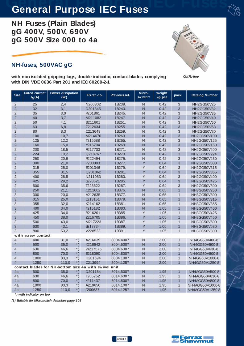
NH Fuses (Plain Blades)gG 400V, 500V, 690V
gG 500V Size 000 to 4a
NH-fuses, 500VAC gG
with non-isolated gripping lugs, double indicator, contact blades, complyingwith DIN VDE 0636 Part 201 and IEC 60269-2-1
Cd/Pb-free
SizeRated current Power dissipation
FS ref.-no. Previous ref.Micro- weight
pack. Catalog NumberIN(A) (W) switch(1) kg/pce
000 2 1,9 B211946 1B613. Y 0,13 3000 4 1,5 M212462 1B619. Y 0,13 3000 6 1,6 D213995 1B623. Y 0,13 3000 10 1,1 B219651 1B631. Y 0,13 3000 16 1,8 K222097 1B635. Y 0,13 9000 20 2,3 A222847 1B637. Y 0,13 9000 25 2,4 E201185 1B639. Y 0,13 9000 32 3,1 Z211438 1B643. Y 0,13 9000 35 3,0 C211947 1B645. Y 0,13 9000 40 3,7 N212463 1B647. Y 0,13 9000 50 4,1 T212974 1B651. Y 0,13 9000 63 5,4 E213996 1B655. Y 0,13 9000 80 6,5 Y216543 1B659. Y 0,13 9000 100 7,5 B219122 1B663. Y 0,13 900 125 10,0 R201863 1B765. Y 0,20 300 160 12,3 P211084 1B769. Y 0,20 30 6 1,6 H213148 1B023. Y 0,27 30 10 1,1 G214159 1B031. Y 0,27 30 16 1,8 Q215179 1B035. Y 0,27 30 20 2,3 R215686 1B037. Y 0,27 30 25 2,4 Y216198 1B039. Y 0,27 30 32 3,1 W216702 1B043. Y 0,27 30 35 3,0 J217220 1B045. Y 0,27 30 40 3,7 P217731 1B047. Y 0,27 30 50 4,1 Z218246 1B051. Y 0,27 30 63 6,6 N218765 1B055. Y 0,27 30 80 8,0 C219284 1B059. Y 0,27 30 100 9,4 D219814 1B063. Y 0,27 30 125 11,8 P222492 1B065. Y 0,27 30 160 14,6 F223013 1B069. Y 0,27 30 200 18,1 C229611 1B071. Y 0,27 30 224 19,2 D229612 1B073. Y 0,27 30 250 20,3 E229613 1B075. Y 0,27 31 16 1,8 M200801 1B135. N 0,28 31 20 2,3 C201344 1B137. N 0,28 31 25 2,4 N201860 1B139. N 0,28 31 32 3,1 L211081 1B143. N 0,28 31 35 3,0 A211600 1B145. N 0,28 31 40 3,7 Y212633 1B147. N 0,28 31 50 4,1 B213648 1B151. N 0,28 31 63 6,6 L214669 1B155. N 0,28 31 80 8,0 S215687 1B159. N 0,28 31 100 9,4 X216703 1B163. N 0,28 31 125 11,8 Q217732 1B165. Y 0,30 31 160 14,6 A218247 1B169. Y 0,30 31 200 18,0 P218766 1B171. Y 0,30 31 224 19,0 D219285 1B173. Y 0,30 31 250 20,0 E219815 1B175. Y 0,30 31 315 20,5 Q228519 1B179. Y 0,42 31 355 23,7 R228520 1B181. Y 0,42 3
(1) Suitable for Microswitch describes page 106
NH000GG50V2NH000GG50V4NH000GG50V6
NH000GG50V10NH000GG50V16NH000GG50V20NH000GG50V25NH000GG50V32NH000GG50V35NH000GG50V40NH000GG50V50NH000GG50V63NH000GG50V80
NH000GG50V100NH00GG50V125NH00GG50V160
NH0GG50V6NH0GG50V10NH0GG50V16NH0GG50V20NH0GG50V25NH0GG50V32NH0GG50V35NH0GG50V40NH0GG50V50NH0GG50V63NH0GG50V80
NH0GG50V100NH0GG50V125NH0GG50V160NH0GG50V200NH0GG50V224NH0GG50V250NH1GG50V16NH1GG50V20NH1GG50V25NH1GG50V32NH1GG50V35NH1GG50V40NH1GG50V50NH1GG50V63NH1GG50V80
NH1GG50V100NH1GG50V125NH1GG50V160NH1GG50V200NH1GG50V224NH1GG50V250NH1GG50V315NH1GG50V355
NH Fuses (Plain Blades)gG 400V, 500V, 690V gG 500V Size 000 to 4a
GPEU17
General Purpose IEC Fuses General Purpose IEC Fuses
NH-fuses, 500VAC gG
Cd/Pb-free
SizeRated current Power dissipation
FS ref.-no. Previous ref.Micro- weight
pack. Catalog NumberIN(A) (W) switch(1) kg/pce
(1) Suitable for Microswitch describes page 106
with non-isolated gripping lugs, double indicator, contact blades, complyingwith DIN VDE 0636 Part 201 and IEC 60269-2-1
2 25 2,4 N200802 1B239. N 0,42 32 32 3,1 D201345 1B243. N 0,42 32 35 3,0 P201861 1B245. N 0,42 32 40 3,7 M211082 1B247. N 0,42 32 50 4,1 B211601 1B251. N 0,42 32 63 6,8 Z212634 1B255. N 0,42 32 80 8,3 C213649 1B259. N 0,42 32 100 10,7 M214670 1B263. N 0,42 32 125 12,2 T215688 1B265. N 0,42 32 160 15,0 Y216704 1B269. N 0,42 32 200 18,5 R217733 1B271. N 0,42 32 224 19,2 Q218767 1B273. N 0,42 32 250 20,6 R222494 1B275. N 0,42 32 300 21,0 P200803 1B277. Y 0,64 32 315 25,0 E201346 1B279. Y 0,64 32 355 31,5 Q201862 1B281. Y 0,64 32 400 28,5 N211083 1B283. Y 0,64 32 425 29,2 S228521 1B285. Y 0,64 32 500 35,6 T228522 1B287. Y 0,64 33 250 21,1 C211602 1B375. N 0,65 13 300 20,0 A212635 1B377. N 0,65 13 315 25,0 L213151 1B379. N 0,65 13 355 32,0 K214162 1B381. N 0,65 13 400 34,0 T215182 1B383. N 1,05 13 425 34,0 B216201 1B385. Y 1,05 13 450 38,0 Z216705 1B386. Y 1,05 13 500 43,0 M217223 1B387. Y 1,05 13 630 43,1 S217734 1B389. Y 1,05 13 800 53,2 V228523 1B391. Y 1,05 1with screw contact4 400 31,0 *) A216039 8004.4007 N 2,00 14 500 35,0 *) X216542 8004.5007 N 2,00 14 630 46,6 *) W217576 8004.6307 N 2,00 14 800 70,0 *) E218090 8004.8007 N 2,00 14 1000 83,3 *) H201694 8004.1007 N 2,00 14 1250 110,0 *) C213994 8004.1257 N 2,00 1contact blades for NH-bottom size 4a with swivel unit4a 500 35,0 *) D201184 8014.5007 N 1,95 14a 630 46,6 *) T205752 8014.6307 N 1,95 14a 800 70,0 *) Y211437 8014.8007 N 1,95 14a 1000 83,3 *) A219650 8014.1007 N 1,95 14a 1250 110,0 *) J200637 8014.1257 N 1,95 1*) with indicator on top
NH2GG50V25NH2GG50V32NH2GG50V35NH2GG50V40NH2GG50V50NH2GG50V63NH2GG50V80
NH2GG50V100NH2GG50V125NH2GG50V160NH2GG50V200NH2GG50V224NH2GG50V250NH2GG50V300NH2GG50V315NH2GG50V355NH2GG50V400NH2GG50V425NH2GG50V500NH3GG50V250NH3GG50V300NH3GG50V315NH3GG50V355NH3GG50V400NH3GG50V425NH3GG50V450NH3GG50V500NH3GG50V630NH3GG50V800
NH4GG50V400-8NH4GG50V500-8NH4GG50V630-8NH4GG50V800-8
NH4GG50V1000-8NH4GG50V1250-8
NH4AGG50V500-8NH4AGG50V630-8NH4AGG50V800-8
NH4AGG50V1000-8NH4AGG50V1250-8
General Purpose IEC Fuses General Purpose IEC Fuses
GPEU18
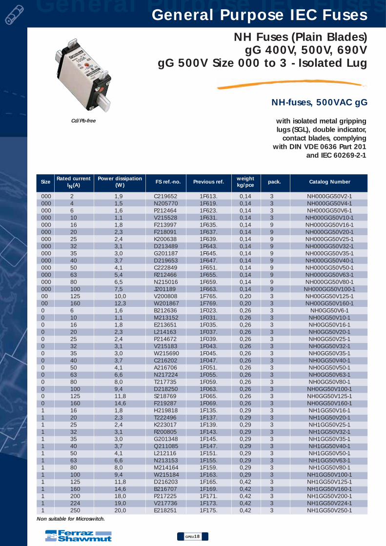
NH Fuses (Plain Blades)gG 400V, 500V, 690V
gG 500V Size 000 to 3 - Isolated Lug
NH-fuses, 500VAC gG
with isolated metal grippinglugs (SGL), double indicator,
contact blades, complyingwith DIN VDE 0636 Part 201
and IEC 60269-2-1
Cd/Pb-free
Non suitable for Microswitch.
SizeRated current Power dissipation
FS ref.-no. Previous ref.weight
pack. Catalog NumberIN(A) (W) kg/pce
000 2 1,9 C219652 1F613. 0,14 3000 4 1,5 N205770 1F619. 0,14 3000 6 1,6 P212464 1F623. 0,14 3000 10 1,1 V215528 1F631. 0,14 3000 16 1,8 F213997 1F635. 0,14 9000 20 2,3 F218091 1F637. 0,14 9000 25 2,4 K200638 1F639. 0,14 9000 32 3,1 D213489 1F643. 0,14 9000 35 3,0 G201187 1F645. 0,14 9000 40 3,7 D219653 1F647. 0,14 9000 50 4,1 C222849 1F651. 0,14 9000 63 5,4 R212466 1F655. 0,14 9000 80 6,5 N215016 1F659. 0,14 9000 100 7,5 J201189 1F663. 0,14 900 125 10,0 V200808 1F765. 0,20 300 160 12,3 W201867 1F769. 0,20 30 6 1,6 B212636 1F023. 0,26 30 10 1,1 M213152 1F031. 0,26 30 16 1,8 E213651 1F035. 0,26 30 20 2,3 L214163 1F037. 0,26 30 25 2,4 P214672 1F039. 0,26 30 32 3,1 V215183 1F043. 0,26 30 35 3,0 W215690 1F045. 0,26 30 40 3,7 C216202 1F047. 0,26 30 50 4,1 A216706 1F051. 0,26 30 63 6,6 N217224 1F055. 0,26 30 80 8,0 T217735 1F059. 0,26 30 100 9,4 D218250 1F063. 0,26 30 125 11,8 S218769 1F065. 0,26 30 160 14,6 F219287 1F069. 0,26 31 16 1,8 H219818 1F135. 0,29 31 20 2,3 T222496 1F137. 0,29 31 25 2,4 K223017 1F139. 0,29 31 32 3,1 R200805 1F143. 0,29 31 35 3,0 G201348 1F145. 0,29 31 40 3,7 Q211085 1F147. 0,29 31 50 4,1 L212116 1F151. 0,29 31 63 6,6 N213153 1F155. 0,29 31 80 8,0 M214164 1F159. 0,29 31 100 9,4 W215184 1F163. 0,29 31 125 11,8 D216203 1F165. 0,42 31 160 14,6 B216707 1F169. 0,42 31 200 18,0 P217225 1F171. 0,42 31 224 19,0 V217736 1F173. 0,42 31 250 20,0 E218251 1F175. 0,42 3
NH000GG50V2-1NH000GG50V4-1NH000GG50V6-1
NH000GG50V10-1NH000GG50V16-1NH000GG50V20-1NH000GG50V25-1NH000GG50V32-1NH000GG50V35-1NH000GG50V40-1NH000GG50V50-1NH000GG50V63-1NH000GG50V80-1
NH000GG50V100-1NH00GG50V125-1NH00GG50V160-1
NH0GG50V6-1NH0GG50V10-1NH0GG50V16-1NH0GG50V20-1NH0GG50V25-1NH0GG50V32-1NH0GG50V35-1NH0GG50V40-1NH0GG50V50-1NH0GG50V63-1NH0GG50V80-1
NH0GG50V100-1NH0GG50V125-1NH0GG50V160-1NH1GG50V16-1NH1GG50V20-1NH1GG50V25-1NH1GG50V32-1NH1GG50V35-1NH1GG50V40-1NH1GG50V50-1NH1GG50V63-1NH1GG50V80-1
NH1GG50V100-1NH1GG50V125-1NH1GG50V160-1NH1GG50V200-1NH1GG50V224-1NH1GG50V250-1

NH Fuses (Plain Blades)gG 400V, 500V, 690V gG 500V Size 000 to 3 - Isolated Lug
GPEU19
General Purpose IEC Fuses General Purpose IEC Fuses
NH-fuses, 500VAC gG
with isolated metal grippinglugs (SGL), double indicator,contact blades, complyingwith DIN VDE 0636 Part 201and IEC 60269-2-1
Cd/Pb-free
Non suitable for Microswitch.
SizeRated current Power dissipation
FS ref.-no. Previous ref.weight
pack. Catalog NumberIN(A) (W) kg/pce
2 25 2,4 J219819 1F239. 0,42 32 32 3,1 V222497 1F243. 0,42 32 35 3,0 L223018 1F245. 0,42 32 40 3,7 S200806 1F247. 0,42 32 50 4,1 H201349 1F251. 0,42 32 63 6,8 T201865 1F255. 0,42 32 80 8,3 F211605 1F259. 0,42 32 100 10,7 P213154 1F263. 0,42 32 125 12,2 N214165 1F265. 0,42 32 160 15,0 X215185 1F269. 0,42 32 200 18,5 E216204 1F271. 0,42 32 224 19,2 Q217226 1F273. 0,42 32 250 20,6 F218252 1F275. 0,42 32 300 21,0 H219289 1F277. 0,64 32 315 25,0 K219820 1F279. 0,64 32 355 31,5 M223019 1F281. 0,64 32 400 28,5 T200807 1F283. 0,64 33 250 21,1 J201350 1F375. 0,65 13 300 20,0 S211087 1F377. 0,65 13 315 25,0 G211606 1F379. 0,65 13 355 32,0 E212639 1F381. 0,65 13 400 34,0 H213654 1F383. 1,05 13 425 34,0 S214675 1F385. 1,05 13 450 38,0 Z215693 1F386. 1,05 13 500 43,0 F216205 1F387. 1,05 13 630 43,1 D216709 1F389. 1,05 1
NH2GG50V25-1NH2GG50V32-1NH2GG50V35-1NH2GG50V40-1NH2GG50V50-1NH2GG50V63-1NH2GG50V80-1
NH2GG50V100-1NH2GG50V125-1NH2GG50V160-1NH2GG50V200-1NH2GG50V224-1NH2GG50V250-1NH2GG50V300-1NH2GG50V315-1NH2GG50V355-1NH2GG50V400-1NH3GG50V250-1NH3GG50V300-1NH3GG50V315-1NH3GG50V355-1NH3GG50V400-1NH3GG50V425-1NH3GG50V450-1NH3GG50V500-1NH3GG50V630-1

General Purpose IEC Fuses General Purpose IEC Fuses
GPEU20
NH Fuses (Plain Blades)gG 400V, 500V, 690V
gG 690V Size 000 to 4a
NH-fuses, 690VAC gG
with non-isolated gripping lugs, doubleindicator, contact blades, complyingwith DIN VDE 0636 Part 201 and IEC 60269-2-1
Cd/Pb-free
SizeRated current Power dissipation
FS ref.-no. Previous ref.Micro- weight
pack. Catalog NumberIN(A) (W) switch(1) kg/pce
000 2 1,9 E228440 1C613. Y 0,13 3000 4 1,5 F228441 1C619. Y 0,13 3000 6 1,6 G228442 1C623. Y 0,13 3000 10 1,1 J228444 1C631. Y 0,13 3000 16 1,8 K228445 1C635. Y 0,13 3000 20 2,3 L228446 1C637. Y 0,13 3000 25 2,4 M228447 1C639. Y 0,13 3000 32 3,1 N228448 1C643. Y 0,13 3000 35 3,0 P228449 1C645. Y 0,13 3000 40 3,7 Q228450 1C647. Y 0,13 3000 50 4,1 R228451 1C651. Y 0,13 3000 63 5,4 S228452 1C655. Y 0,13 3000 80 6,5 T228453 1C659. Y 0,13 300 32 3,1 V228454 1C743. Y 0,20 300 35 3,0 W228455 1C745. Y 0,20 300 40 3,7 X228456 1C747. Y 0,20 300 50 4,1 Y228457 1C751. Y 0,20 300 63 5,6 Z228458 1C755. Y 0,20 300 80 6,8 A228459 1C759. Y 0,20 300 100 7,5 B228460 1C763. Y 0,20 300 125 10,0 C228461 1C765. Y 0,20 30 6 1,6 D228462 1C023. Y 0,27 30 10 1,1 E228463 1C031. Y 0,27 30 16 1,8 F228464 1C035. Y 0,27 30 20 2,3 G228465 1C037. Y 0,27 30 25 2,4 H228466 1C039. Y 0,27 30 32 3,1 J228467 1C043. Y 0,27 30 35 3,0 K228468 1C045. Y 0,27 30 40 3,7 L228469 1C047. Y 0,27 30 50 4,1 M228470 1C051. Y 0,27 30 63 6,6 N228471 1C055. Y 0,27 30 80 8,0 P228472 1C059. Y 0,27 30 100 9,4 Q228473 1C063. Y 0,27 30 125 11,8 R228474 1C065. Y 0,27 30 160 14,6 S228475 1C069. Y 0,27 31 16 1,8 T228476 1C135. N 0,26 31 20 2,3 V228477 1C137. N 0,26 31 25 2,4 W228478 1C139. N 0,26 31 32 3,1 X228479 1C143. N 0,26 31 35 3,0 Y228480 1C145. N 0,26 31 40 3,7 Z228481 1C147. N 0,26 31 50 4,1 A228482 1C151. N 0,26 31 63 6,6 B228483 1C155. N 0,26 31 80 8,0 C228484 1C159. N 0,26 31 100 9,4 D228485 1C163. N 0,26 31 125 11,8 E228486 1C165. N 0,42 31 160 14,6 F228487 1C169. N 0,42 31 200 18,0 G228488 1C171. Y 0,42 31 224 19,0 V233261 1C173. Y 0,42 31 250 20,0 W233262 1C175. Y 0,42 3
(1) Suitable for Microswitch describes page 106
NH000GG69V2NH000GG69V4NH000GG69V6
NH000GG69V10NH000GG69V16NH000GG69V20NH000GG69V25NH000GG69V32NH000GG69V35NH000GG69V40NH000GG69V50NH000GG69V63NH000GG69V80NH00GG69V32NH00GG69V35NH00GG69V40NH00GG69V50NH00GG69V63NH00GG69V80
NH00GG69V100NH00GG69V125
NH0GG69V6NH0GG69V10NH0GG69V16NH0GG69V20NH0GG69V25NH0GG69V32NH0GG69V35NH0GG69V40NH0GG69V50NH0GG69V63NH0GG69V80
NH0GG69V100NH0GG69V125NH0GG69V160NH1GG69V16NH1GG69V20NH1GG69V25NH1GG69V32NH1GG69V35NH1GG69V40NH1GG69V50NH1GG69V63NH1GG69V80
NH1GG69V100NH1GG69V125NH1GG69V160NH1GG69V200NH1GG69V224NH1GG69V250

NH Fuses (Plain Blades)gG 400V, 500V, 690V gG 690V Size 000 to 4a
GPEU21
General Purpose IEC Fuses General Purpose IEC Fuses
NH-fuses, 690VAC gG
Cd/Pb-free
SizeRated current Power dissipation
FS ref.-no. Previous ref.Micro- weight
pack. Catalog NumberIN(A) (W) switch(1) kg/pce
(1) Suitable for Microswitch describes page 106
with non-isolated gripping lugs, doubleindicator, contact blades, complyingwith DIN VDE 0636 Part 201 and IEC 60269-2-1
2 32 3,1 H228489 1C243. N 0,42 32 35 3,0 J228490 1C245. N 0,42 32 40 3,7 K228491 1C247. N 0,42 32 50 4,1 L228492 1C251. N 0,42 32 63 6,8 M228493 1C255. N 0,42 32 80 8,3 N228494 1C259. N 0,42 32 100 10,7 P228495 1C263. N 0,42 32 125 12,2 Q228496 1C265. Y 0,42 32 160 15,0 R228497 1C269. Y 0,42 32 200 18,5 S228498 1C271. Y 0,42 32 224 19,2 T228499 1C273. Y 0,42 32 250 20,6 V228500 1C275. Y 0,42 32 300 21,0 W228501 1C277. Y 0,64 32 315 25,0 X228502 1C279. Y 0,65 32 355 31,5 Y228503 1C281. Y 0,65 33 250 21,1 Z228504 1C375. N 0,65 13 300 22,6 A228505 1C377. N 0,65 13 315 25,0 B228506 1C379. Y 0,65 13 355 32,0 C228507 1C381. Y 0,65 13 400 34,0 D228508 1C383. Y 1,05 13 425 34,0 E228509 1C385. Y 1,05 13 500 43,0 F228510 1C387. Y 1,05 1with screw contact4 400 31,0 *) N214004 8004.400765 N 2,00 14 500 35,0 *) Y215025 8004.500765 N 2,00 14 630 46,6 *) E215537 8004.630765 N 2,00 14 800 70,0 *) K216554 8004.800765 N 2,00 1contact blades for NH-bottom size 4a with swivel unit4a 400 31,0 *) W217070 8014.400765 N 1,95 14a 500 35,0 *) H217587 8014.500765 N 1,95 14a 630 46,6 *) W222107 8014.630765 N 1,95 14a 800 70,0 *) M222858 8014.800765 N 1,95 1*) with indicator on top
NH2GG69V32NH2GG69V35NH2GG69V40NH2GG69V50NH2GG69V63NH2GG69V80
NH2GG69V100NH2GG69V125NH2GG69V160NH2GG69V200NH2GG69V224NH2GG69V250NH2GG69V300NH2GG69V315NH2GG69V355NH3GG69V250NH3GG69V300NH3GG69V315NH3GG69V355NH3GG69V400NH3GG69V425NH3GG69V500
NH4GG69V400-8NH4GG69V500-8NH4GG69V630-8NH4GG69V800-8
NH4AGG69V400-8NH4AGG69V500-8NH4AGG69V630-8NH4AGG69V800-8
General Purpose IEC Fuses General Purpose IEC Fuses
GPEU22
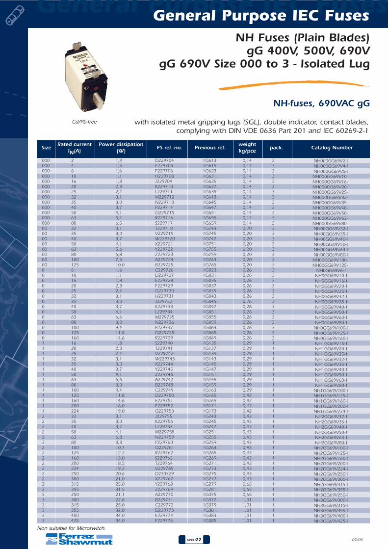
NH Fuses (Plain Blades)gG 400V, 500V, 690V
gG 690V Size 000 to 3 - Isolated Lug
NH-fuses, 690VAC gG
07/05
with isolated metal gripping lugs (SGL), double indicator, contact blades,complying with DIN VDE 0636 Part 201 and IEC 60269-2-1
Cd/Pb-free
Non suitable for Microswitch.
SizeRated current Power dissipation
FS ref.-no. Previous ref.weight
pack. Catalog NumberIN(A) (W) kg/pce
000 2 1,9 D229704 1G613. 0,14 3000 4 1,5 E229705 1G619. 0,14 3000 6 1,6 F229706 1G623. 0,14 3000 10 1,1 H229708 1G631. 0,14 3000 16 1,8 J229709 1G635. 0,14 3000 20 2,3 K229710 1G637. 0,14 3000 25 2,4 L229711 1G639. 0,14 3000 32 3,1 M229712 1G643. 0,14 3000 35 3,0 N229713 1G645. 0,14 3000 40 3,7 P229714 1G647. 0,14 3000 50 4,1 Q229715 1G651. 0,14 3000 63 5,4 R229716 1G655. 0,14 3000 80 6,5 S229717 1G659. 0,14 300 32 3,1 T229718 1G743. 0,20 300 35 3,0 V229719 1G745. 0,20 300 40 3,7 W229720 1G747. 0,20 300 50 4,1 X229721 1G751. 0,20 300 63 5,6 Y229722 1G755. 0,20 300 80 6,8 Z229723 1G759. 0,20 300 100 7,5 A229724 1G763. 0,20 300 125 10,0 B229725 1G765. 0,20 30 6 1,6 C229726 1G023. 0,26 30 10 1,1 D229727 1G031. 0,26 30 16 1,8 E229728 1G035. 0,26 30 20 2,3 F229729 1G037. 0,26 30 25 2,4 G229730 1G039. 0,26 30 32 3,1 H229731 1G043. 0,26 30 35 3,0 J229732 1G045. 0,26 30 40 3,7 K229733 1G047. 0,26 30 50 4,1 L229734 1G051. 0,26 30 63 6,6 M229735 1G055. 0,26 30 80 8,0 N229736 1G059. 0,26 30 100 9,4 P229737 1G063. 0,26 30 125 11,8 Q229738 1G065. 0,26 30 160 14,6 R229739 1G069. 0,26 31 16 1,8 S229740 1G135. 0,29 11 20 2,3 T229741 1G137. 0,29 11 25 2,4 V229742 1G139. 0,29 11 32 3,1 W229743 1G143. 0,29 11 35 3,0 X229744 1G145. 0,29 11 40 3,7 Y229745 1G147. 0,29 11 50 4,1 Z229746 1G151. 0,29 11 63 6,6 A229747 1G155. 0,29 11 80 8,0 B229748 1G159. 0,29 11 100 9,4 C229749 1G163. 0,29 11 125 11,8 D229750 1G165. 0,42 11 160 14,6 E229751 1G169. 0,42 11 200 18,0 F229752 1G171. 0,42 11 224 19,0 G229753 1G173. 0,42 12 32 3,1 J229755 1G243. 0,43 12 35 3,0 K229756 1G245. 0,43 12 40 3,7 L229757 1G247. 0,43 12 50 4,1 M229758 1G251. 0,43 12 63 6,8 N229759 1G255. 0,43 12 80 8,3 P229760 1G259. 0,43 12 100 10,7 Q229761 1G263. 0,43 12 125 12,2 R229762 1G265. 0,43 12 160 15,0 S229763 1G269. 0,43 12 200 18,5 T229764 1G271. 0,43 12 224 19,2 V229765 1G273. 0,43 12 250 20,6 D233729 1G275. 0,43 12 300 21,0 X229767 1G277. 0,43 12 315 25,0 Y229768 1G279. 0,65 12 355 31,5 Z229769 1G281. 0,65 13 250 21,1 A229770 1G375. 0,65 13 300 22,6 B229771 1G377. 1,01 13 315 25,0 C229772 1G379. 1,01 13 355 32,0 D229773 1G381. 1,01 13 400 34,0 E229774 1G383. 1,01 13 425 34,0 F229775 1G385. 1,01 1
NH000GG69V2-1NH000GG69V4-1NH000GG69V6-1
NH000GG69V10-1NH000GG69V16-1NH000GG69V20-1NH000GG69V25-1NH000GG69V32-1NH000GG69V35-1NH000GG69V40-1NH000GG69V50-1NH000GG69V63-1NH000GG69V80-1NH00GG69V32-1NH00GG69V35-1NH00GG69V40-1NH00GG69V50-1NH00GG69V63-1NH00GG69V80-1
NH00GG69V100-1NH00GG69V125-1
NH0GG69V6-1NH0GG69V10-1NH0GG69V16-1NH0GG69V20-1NH0GG69V25-1NH0GG69V32-1NH0GG69V35-1NH0GG69V40-1NH0GG69V50-1NH0GG69V63-1NH0GG69V80-1
NH0GG69V100-1NH0GG69V125-1NH0GG69V160-1NH1GG69V16-1NH1GG69V20-1NH1GG69V25-1NH1GG69V32-1NH1GG69V35-1NH1GG69V40-1NH1GG69V50-1NH1GG69V63-1NH1GG69V80-1
NH1GG69V100-1NH1GG69V125-1NH1GG69V160-1NH1GG69V200-1NH1GG69V224-1NH2GG69V32-1NH2GG69V35-1NH2GG69V40-1NH2GG69V50-1NH2GG69V63-1NH2GG69V80-1
NH2GG69V100-1NH2GG69V125-1NH2GG69V160-1NH2GG69V200-1NH2GG69V224-1NH2GG69V250-1NH2GG69V300-1NH2GG69V315-1NH2GG69V355-1NH3GG69V250-1NH3GG69V300-1NH3GG69V315-1NH3GG69V355-1NH3GG69V400-1NH3GG69V425-1
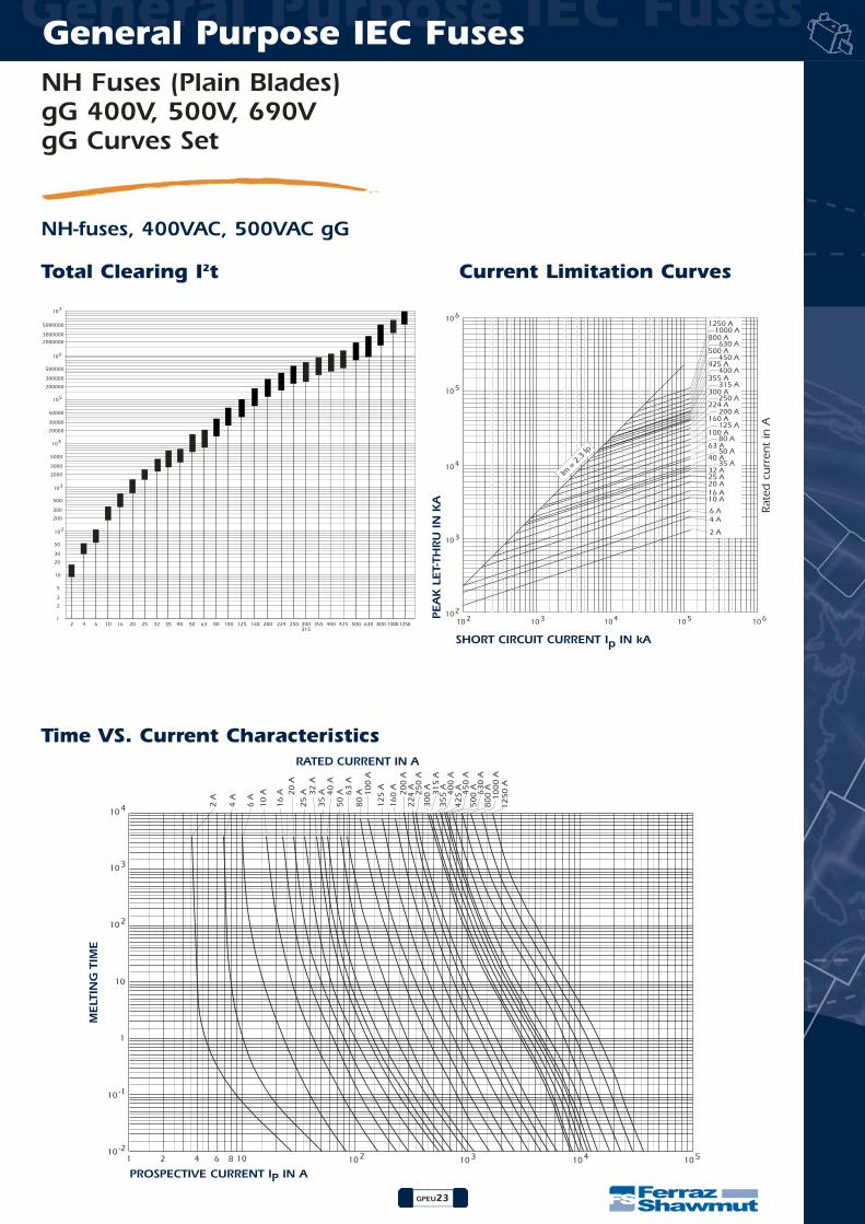
NH Fuses (Plain Blades)gG 400V, 500V, 690V gG Curves Set
GPEU23
General Purpose IEC Fuses General Purpose IEC Fuses
NH-fuses, 400VAC, 500VAC gG
103102102
103
104
105
106
104 105 106
2 A
4 A6 A
10 A16 A20 A25 A32 A
40 A
63 A
100 A
160 A
224 A
300 A
355 A
425 A
500 A
800 A
1250 A
35 A
50 A
80 A
125 A
200 A
250 A
315 A
400 A
450 A
630 A
1000 A
Im =
2.3
Ip
2 4 6 10 16 20 25
104
103
102
105
106
107
10
20
30
50
1
2
3
5
200
300
500
2000
3000
5000
20000
30000
50000
200000
300000
500000
2000000
3000000
5000000
32 35 40 50 63 80 100 125 160 200 224 250 300315
355 400 425 500 630 800 1000 1250
Total Clearing I2t Current Limitation Curves
10210 -2
10 -1
102
103
104
10 103 104 1051 2 4 6 8
2 A
4 A
6 A
10
A
16
A 20
A
32
A
40
A
63
A
10
0 A
20
0 A
25
0 A
35
5 A31
5 A
42
5 A
50
0 A
80
0 A
12
50
A
25
A
35
A
50
A
80
A
12
5 A
16
0 A
22
4 A 40
0 A
45
0 A
63
0 A
10
00
A
30
0 A
1
10
Time VS. Current CharacteristicsRATED CURRENT IN A
MELT
ING
TIM
E
PROSPECTIVE CURRENT IP IN A
PEA
K L
ET-
THRU
IN
KA
SHORT CIRCUIT CURRENT Ip IN kA
Rate
d c
urr
ent
in A
General Purpose IEC Fuses General Purpose IEC Fuses
GPEU24
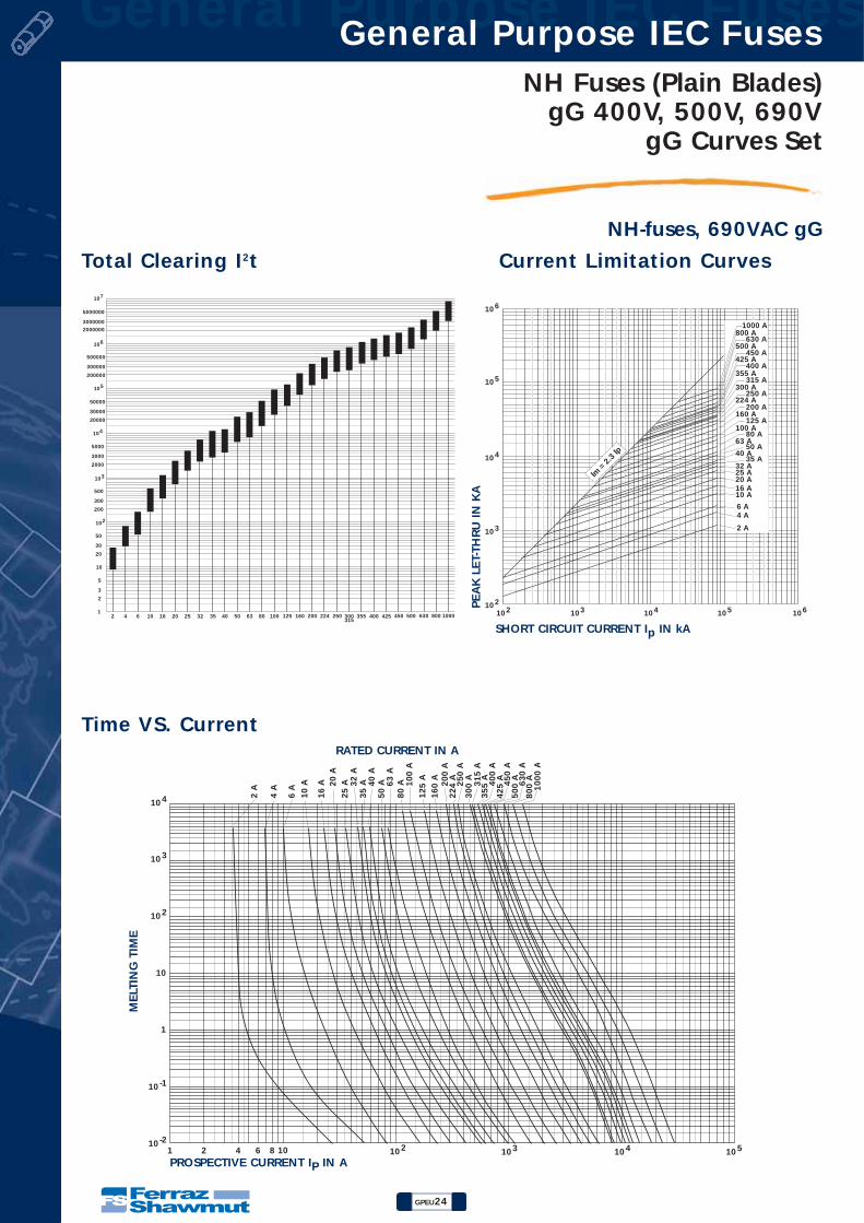
NH Fuses (Plain Blades)gG 400V, 500V, 690V
gG Curves Set
NH-fuses, 690VAC gG
103102102
103
104
105
106
104 105 106
2 A
4 A6 A
10 A16 A20 A25 A32 A
40 A
63 A
100 A
160 A
224 A
300 A
355 A
425 A
500 A
800 A
35 A
50 A
80 A
125 A
200 A
250 A
315 A
400 A
450 A
630 A
1000 A
Im =
2.3
Ip
2 4 6 10 16 20 25 32 35 40 50 63 80 100
104
103
102
105
106
107
10
20
30
50
1
2
3
5
200
300
500
2000
3000
5000
20000
30000
50000
200000
300000
500000
2000000
3000000
5000000
125 160 200 224 250 300315
355 400 425 450 500 630 800 1000
10210 -2
10 -1
102
103
104
10 103 104 1051 2 4 6 8
2 A
4 A
6 A
10
A
16
A 20
A
32
A
40
A
63
A
10
0 A
20
0 A
25
0 A
35
5 A31
5 A
42
5 A
50
0 A
80
0 A
25
A
35
A
50
A
80
A
12
5 A
16
0 A
22
4 A 40
0 A
45
0 A
63
0 A
10
00
A
30
0 A
1
10
PEA
K L
ET-
THRU
IN
KA
Total Clearing I2t Current Limitation Curves
Time VS. CurrentRATED CURRENT IN A
MELT
ING
TIM
E
PROSPECTIVE CURRENT IP IN A
SHORT CIRCUIT CURRENT Ip IN kA
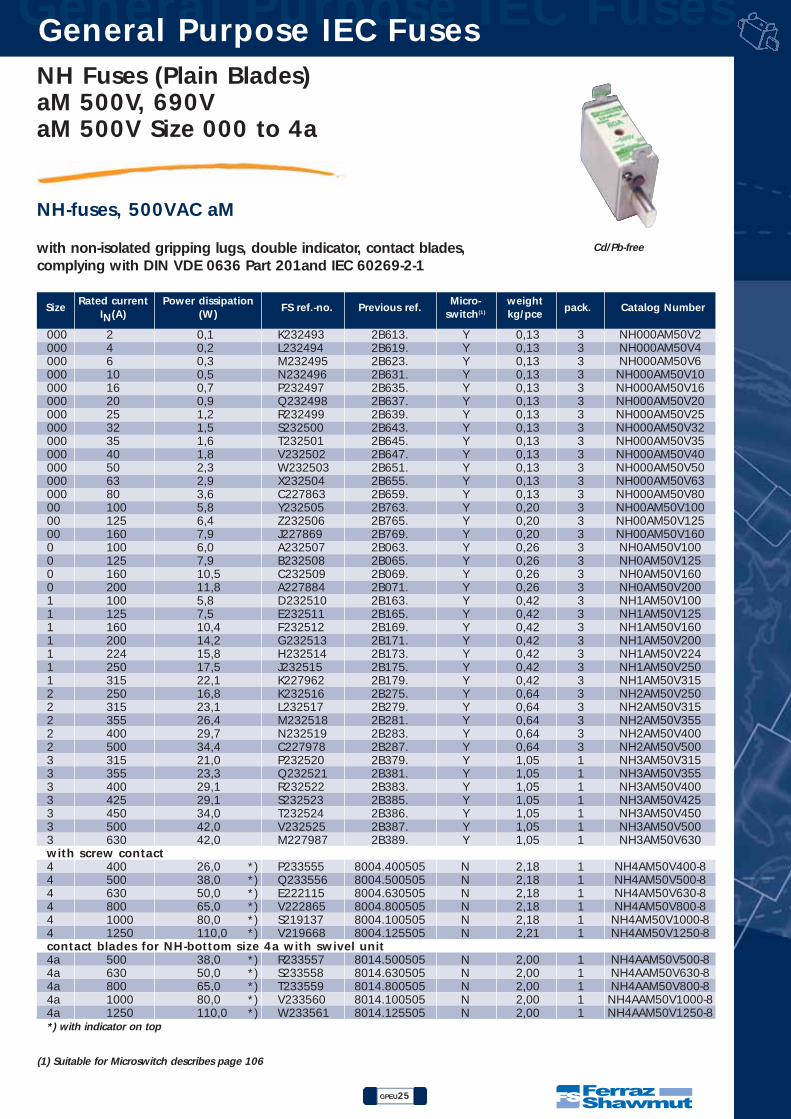
NH Fuses (Plain Blades)aM 500V, 690V aM 500V Size 000 to 4a
GPEU25
General Purpose IEC Fuses General Purpose IEC Fuses
NH-fuses, 500VAC aM
Cd/Pb-free
SizeRated current Power dissipation
FS ref.-no. Previous ref.Micro- weight
pack. Catalog NumberIN(A) (W) switch(1) kg/pce
(1) Suitable for Microswitch describes page 106
with non-isolated gripping lugs, double indicator, contact blades,complying with DIN VDE 0636 Part 201and IEC 60269-2-1
000 2 0,1 K232493 2B613. Y 0,13 3000 4 0,2 L232494 2B619. Y 0,13 3000 6 0,3 M232495 2B623. Y 0,13 3000 10 0,5 N232496 2B631. Y 0,13 3000 16 0,7 P232497 2B635. Y 0,13 3000 20 0,9 Q232498 2B637. Y 0,13 3000 25 1,2 R232499 2B639. Y 0,13 3000 32 1,5 S232500 2B643. Y 0,13 3000 35 1,6 T232501 2B645. Y 0,13 3000 40 1,8 V232502 2B647. Y 0,13 3000 50 2,3 W232503 2B651. Y 0,13 3000 63 2,9 X232504 2B655. Y 0,13 3000 80 3,6 C227863 2B659. Y 0,13 300 100 5,8 Y232505 2B763. Y 0,20 300 125 6,4 Z232506 2B765. Y 0,20 300 160 7,9 J227869 2B769. Y 0,20 30 100 6,0 A232507 2B063. Y 0,26 30 125 7,9 B232508 2B065. Y 0,26 30 160 10,5 C232509 2B069. Y 0,26 30 200 11,8 A227884 2B071. Y 0,26 31 100 5,8 D232510 2B163. Y 0,42 31 125 7,5 E232511 2B165. Y 0,42 31 160 10,4 F232512 2B169. Y 0,42 31 200 14,2 G232513 2B171. Y 0,42 31 224 15,8 H232514 2B173. Y 0,42 31 250 17,5 J232515 2B175. Y 0,42 31 315 22,1 K227962 2B179. Y 0,42 32 250 16,8 K232516 2B275. Y 0,64 32 315 23,1 L232517 2B279. Y 0,64 32 355 26,4 M232518 2B281. Y 0,64 32 400 29,7 N232519 2B283. Y 0,64 32 500 34,4 C227978 2B287. Y 0,64 33 315 21,0 P232520 2B379. Y 1,05 13 355 23,3 Q232521 2B381. Y 1,05 13 400 29,1 R232522 2B383. Y 1,05 13 425 29,1 S232523 2B385. Y 1,05 13 450 34,0 T232524 2B386. Y 1,05 13 500 42,0 V232525 2B387. Y 1,05 13 630 42,0 M227987 2B389. Y 1,05 1with screw contact4 400 26,0 *) P233555 8004.400505 N 2,18 14 500 38,0 *) Q233556 8004.500505 N 2,18 14 630 50,0 *) E222115 8004.630505 N 2,18 14 800 65,0 *) V222865 8004.800505 N 2,18 14 1000 80,0 *) S219137 8004.100505 N 2,18 14 1250 110,0 *) V219668 8004.125505 N 2,21 1contact blades for NH-bottom size 4a with swivel unit4a 500 38,0 *) R233557 8014.500505 N 2,00 14a 630 50,0 *) S233558 8014.630505 N 2,00 14a 800 65,0 *) T233559 8014.800505 N 2,00 14a 1000 80,0 *) V233560 8014.100505 N 2,00 14a 1250 110,0 *) W233561 8014.125505 N 2,00 1*) with indicator on top
NH000AM50V2NH000AM50V4NH000AM50V6
NH000AM50V10NH000AM50V16NH000AM50V20NH000AM50V25NH000AM50V32NH000AM50V35NH000AM50V40NH000AM50V50NH000AM50V63NH000AM50V80NH00AM50V100NH00AM50V125NH00AM50V160NH0AM50V100NH0AM50V125NH0AM50V160NH0AM50V200NH1AM50V100NH1AM50V125NH1AM50V160NH1AM50V200NH1AM50V224NH1AM50V250NH1AM50V315NH2AM50V250NH2AM50V315NH2AM50V355NH2AM50V400NH2AM50V500NH3AM50V315NH3AM50V355NH3AM50V400NH3AM50V425NH3AM50V450NH3AM50V500NH3AM50V630
NH4AM50V400-8NH4AM50V500-8NH4AM50V630-8NH4AM50V800-8
NH4AM50V1000-8NH4AM50V1250-8
NH4AAM50V500-8NH4AAM50V630-8NH4AAM50V800-8
NH4AAM50V1000-8NH4AAM50V1250-8
General Purpose IEC Fuses General Purpose IEC Fuses
GPEU26
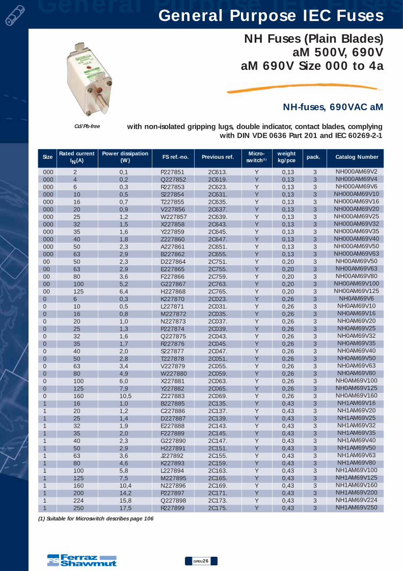
NH Fuses (Plain Blades)aM 500V, 690V
aM 690V Size 000 to 4a
NH-fuses, 690VAC aM
with non-isolated gripping lugs, double indicator, contact blades, complyingwith DIN VDE 0636 Part 201 and IEC 60269-2-1
Cd/Pb-free
SizeRated current Power dissipation
FS ref.-no. Previous ref.Micro- weight
pack. Catalog NumberIN(A) (W) switch(1) kg/pce
000 2 0,1 P227851 2C613. Y 0,13 3000 4 0,2 Q227852 2C619. Y 0,13 3000 6 0,3 R227853 2C623. Y 0,13 3000 10 0,5 S227854 2C631. Y 0,13 3000 16 0,7 T227855 2C635. Y 0,13 3000 20 0,9 V227856 2C637. Y 0,13 3000 25 1,2 W227857 2C639. Y 0,13 3000 32 1,5 X227858 2C643. Y 0,13 3000 35 1,6 Y227859 2C645. Y 0,13 3000 40 1,8 Z227860 2C647. Y 0,13 3000 50 2,3 A227861 2C651. Y 0,13 3000 63 2,9 B227862 2C655. Y 0,13 300 50 2,3 D227864 2C751. Y 0,20 300 63 2,9 E227865 2C755. Y 0,20 300 80 3,6 F227866 2C759. Y 0,20 300 100 5,2 G227867 2C763. Y 0,20 300 125 6,4 H227868 2C765. Y 0,20 30 6 0,3 K227870 2C023. Y 0,26 30 10 0,5 L227871 2C031. Y 0,26 30 16 0,8 M227872 2C035. Y 0,26 30 20 1,0 N227873 2C037. Y 0,26 30 25 1,3 P227874 2C039. Y 0,26 30 32 1,6 Q227875 2C043. Y 0,26 30 35 1,7 R227876 2C045. Y 0,26 30 40 2,0 S227877 2C047. Y 0,26 30 50 2,8 T227878 2C051. Y 0,26 30 63 3,4 V227879 2C055. Y 0,26 30 80 4,9 W227880 2C059. Y 0,26 30 100 6,0 X227881 2C063. Y 0,26 30 125 7,9 Y227882 2C065. Y 0,26 30 160 10,5 Z227883 2C069. Y 0,26 31 16 1,0 B227885 2C135. Y 0,43 31 20 1,2 C227886 2C137. Y 0,43 31 25 1,4 D227887 2C139. Y 0,43 31 32 1,9 E227888 2C143. Y 0,43 31 35 2,0 F227889 2C145. Y 0,43 31 40 2,3 G227890 2C147. Y 0,43 31 50 2,9 H227891 2C151. Y 0,43 31 63 3,6 J227892 2C155. Y 0,43 31 80 4,6 K227893 2C159. Y 0,43 31 100 5,8 L227894 2C163. Y 0,43 31 125 7,5 M227895 2C165. Y 0,43 31 160 10,4 N227896 2C169. Y 0,43 31 200 14,2 P227897 2C171. Y 0,43 31 224 15,8 Q227898 2C173. Y 0,43 31 250 17,5 R227899 2C175. Y 0,43 3
(1) Suitable for Microswitch describes page 106
NH000AM69V2NH000AM69V4NH000AM69V6
NH000AM69V10NH000AM69V16NH000AM69V20NH000AM69V25NH000AM69V32NH000AM69V35NH000AM69V40NH000AM69V50NH000AM69V63NH00AM69V50NH00AM69V63NH00AM69V80
NH00AM69V100NH00AM69V125
NH0AM69V6NH0AM69V10NH0AM69V16NH0AM69V20NH0AM69V25NH0AM69V32NH0AM69V35NH0AM69V40NH0AM69V50NH0AM69V63NH0AM69V80
NH0AM69V100NH0AM69V125NH0AM69V160NH1AM69V16NH1AM69V20NH1AM69V25NH1AM69V32NH1AM69V35NH1AM69V40NH1AM69V50NH1AM69V63NH1AM69V80
NH1AM69V100NH1AM69V125NH1AM69V160NH1AM69V200NH1AM69V224NH1AM69V250

NH Fuses (Plain Blades)aM 500V, 690V aM 690V Size 000 to 4a
GPEU27
General Purpose IEC Fuses General Purpose IEC Fuses
NH-fuses, 690VAC aM
Cd/Pb-free
SizeRated current Power dissipation
FS ref.-no. Previous ref.Micro- weight
pack. Catalog NumberIN(A) (W) switch(1) kg/pce
(1) Suitable for Microswitch describes page 106
with non-isolated gripping lugs, double indicator, contact blades,complying with DIN VDE 0636 Part 201and IEC 60269-2-1
2 35 1,8 L227963 2C245. Y 0,64 32 40 2,1 M227964 2C247. Y 0,64 32 50 2,7 N227965 2C251. Y 0,64 32 63 3,4 P227966 2C255. Y 0,64 32 80 4,4 Q227967 2C259. Y 0,64 32 100 5,5 R227968 2C263. Y 0,64 32 125 6,4 S227969 2C265. Y 0,64 32 160 9,3 T227970 2C269. Y 0,64 32 200 11,3 V227971 2C271. Y 0,64 32 224 12,2 W227972 2C273. Y 0,64 32 250 16,8 X227973 2C275. Y 0,64 32 300 21,0 Y227974 2C277. Y 0,64 32 315 23,1 Z227975 2C279. Y 0,64 32 355 26,4 A227976 2C281. Y 0,64 32 400 29,7 B227977 2C283. Y 0,64 33 250 14,6 D227979 2C375. Y 1,05 13 300 21,0 E227980 2C377. Y 1,05 13 315 21,0 F227981 2C379. Y 1,05 13 355 23,3 G227982 2C381. Y 1,05 13 400 29,1 H227983 2C383. Y 1,05 13 425 29,1 J227984 2C385. Y 1,05 13 450 34,0 K227985 2C386. Y 1,05 13 500 42,0 L227986 2C387. Y 1,05 1with screw contact4 400 26,0 *) Q227990 8004.40056 N 2,00 14 500 38,0 *) R227991 8004.50056 N 2,00 14 630 50,0 *) S227992 8004.63056 N 1,75 14 800 65,0 *) T227993 8004.80056 N 1,75 14 1000 80,0 *) V227994 8004.10056 N 2,00 1contact blades for NH-bottom size 4a with swivel unit4a 500 38,0 *) X227996 8014.50056 N 1,95 14a 630 50,0 *) Y227997 8014.63056 N 1,95 14a 800 65,0 *) A227999 8014.80056 N 1,95 14a 1000 80,0 *) B228000 8014.10056 N 1,95 1*) with indicator on top
NH2AM69V35NH2AM69V40NH2AM69V50NH2AM69V63NH2AM69V80
NH2AM69V100NH2AM69V125NH2AM69V160NH2AM69V200NH2AM69V224NH2AM69V250NH2AM69V300NH2AM69V315NH2AM69V355NH2AM69V400NH3AM69V250NH3AM69V300NH3AM69V315NH3AM69V355NH3AM69V400NH3AM69V425NH3AM69V450NH3AM69V500
NH4AM69V400-8NH4AM69V500-8NH4AM69V630-8NH4AM69V800-8
NH4AM69V1000-8
NH4AAM69V500-8NH4AAM69V630-8NH4AAM69V800-8
NH4AAM69V1000-8
General Purpose IEC Fuses General Purpose IEC Fuses
GPEU28
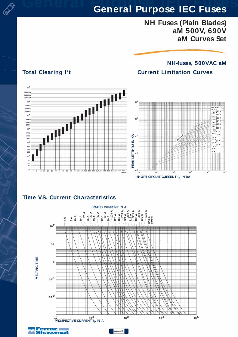
NH Fuses (Plain Blades)aM 500V, 690V
aM Curves Set
NH-fuses, 500VAC aM
PEA
K L
ET-
THRU
IN
KA
Total Clearing I2t Current Limitation Curves
Time VS. Current Characteristics
RATED CURRENT IN A
MELT
ING
TIM
E
PROSPECTIVE CURRENT IP IN A
SHORT CIRCUIT CURRENT Ip IN kA
10210102
103
104
105
106
10 3 104 105 106
32 A
6 A
4 A
10 A
20 A
40 A
16 A
25 A
63 A
100 A
160 A
224 A
315 A
400 A
500 A
35 A
50 A
80 A
125 A
200 A
250 A
355 A
450 A
630 A800 A (400 V)
Im =
2.3
Ip
102
103
104
106
107
4 6 10 16 20 25 32 35 40 50 63 80
105
10
20
30
50
200
300
500
2000
3000
5000
20000
30000
50000
200000
300000
500000
2000000
3000000
5000000
100 125 160 200 224 250 315 355 400 450 500 630 800(400V)
10 -2
10 -1
102
10210 103 104 105
6 A
10
A
16
A 20
A
32
A
40
A
63
A
10
0 A
20
0 A
25
0 A
40
0 A35
5 A
50
0 A
80
0 A
(400
V)
25
A
35
A
50
A
80
A
12
5 A
16
0 A
22
4 A 45
0 A
63
0 A
31
5 A
1
10
4 A

NH Fuses (Plain Blades)aM 500V, 690V aM Curves Set
GPEU29
General Purpose IEC Fuses General Purpose IEC Fuses
NH-fuses, 690VAC aM
PEA
K L
ET-
THRU
IN
KA
Total Clearing I2t Current Limitation Curves
Time VS. Current CharacteristicsRATED CURRENT IN A
MELT
ING
TIM
E
PROSPECTIVE CURRENT IP IN A
SHORT CIRCUIT CURRENT Ip IN kA
10210102
103
104
105
106
10 3 104 105 106
32 A
6 A
4 A
10 A
20 A
40 A
16 A
25 A
63 A
100 A
160 A
224 A
315 A
400 A
500 A
35 A
50 A
80 A
125 A
200 A
250 A
355 A
450 A
Im =
2.3
Ip
102
103
104
106
107
4 6 10 16 20 25 32 35 40 50 63 80
105
10
20
30
50
200
300
500
2000
3000
5000
20000
30000
50000
200000
300000
500000
2000000
3000000
5000000
100 125 160 200 224 250 315 355 400 450 500
10 -2
10 -1
102
10210 103 104 105
6 A
10
A
16
A 20
A
32
A
40
A
63
A
10
0 A
20
0 A
25
0 A
40
0 A35
5 A
50
0 A
25
A
35
A
50
A
80
A
12
5 A
16
0 A
22
4 A 45
0 A
31
5 A
1
10
4 A

General Purpose IEC Fuses General Purpose IEC Fuses
GPEU30
NH Fuses (Plain Blades)400V gTr
NH-fuses, 400VAC gTr
with non-isolated grippinglugs, double indicator,
contact blades, complyingwith DIN VDE 0636 Part 22,
DIN VDE 0636 Part 201
(2) These fuses are able to operate it 500VAC (tested at 550V +0 +5%).
Size VoltageTransformer Rated current Power dissipation
FS ref.-no. Previous ref.weight
pack. Catalog Numbercapacity (kVA) IN(A) (W) kg/pce
2 400 50,0 72 H232813(2) 5A251. 0,37 12 400 75,0 108 G232812(2) 5A257. 0,37 12 400 100,0 145 12,0 B232807(2) 5A263. 0,37 12 400 125,0 181 15,0 C232808(2) 5A265. 0,37 12 400 160,0 231 18,4 D232809(2) 5A269. 0,37 12 400 200,0 289 22,0 E232810(2) 5A271. 0,37 12 400 250,0 361 27,0 F232811(2) 5A275. 0,37 13 400 250,0 361 26,0 J232814(2) 5A375. 0,61 13 400 315,0 455 34,0 K232815(2) 5A379. 0,61 13 400 400,0 578 39,0 L232816(2) 5A383. 0,61 13 400 500,0 723 M232817 5A387. 0,81 13 400 630,0 910 N232818 5A389. 0,81 1contact blades for NH-bottom size 4a with swivel unit4a 400 100,0 145 11,4 *) T212997 8008.100005 2,09 14a 400 125,0 181 14,5 *) Y213507 8008.125005 2,17 14a 400 160,0 231 17,8 *) Z214014 8008.160005 1,95 14a 400 200,0 289 20,6 *) C214523 8008.200005 1,95 14a 400 250,0 361 25,7 *) F215032 8008.250005 2,13 14a 400 315,0 455 33,2 *) M215544 8008.315005 1,95 14a 400 400,0 578 38,1 *) S216055 8008.400005 1,95 14a 400 500,0 723 53,2 *) V216563 8008.500005 1,95 14a 400 630,0 910 68,7 *) E217078 8008.630005 1,95 14a 400 800,0 1155 90,4 *) R217595 8008.800005 2,10 1*) with indicator on top
NH2GTR50KVANH2GTR75KVANH2GTR100KVANH2GTR125KVANH2GTR160KVANH2GTR200KVANH2GTR250KVANH3GTR250KVANH3GTR315KVANH3GTR400KVANH3GTR500KVANH3GTR630KVA
NH4AGTR100KVA-8NH4AGTR125KVA-8NH4AGTR160KVA-8NH4AGTR200KVA-8NH4AGTR250KVA-8NH4AGTR315KVA-8NH4AGTR400KVA-8NH4AGTR500KVA-8NH4AGTR630KVA-8NH4AGTR800KVA-8

NH Fuses (Plain Blades)400V gTr gTr Curves Set
GPEU31
General Purpose IEC Fuses General Purpose IEC Fuses
NH-fuses, 400VAC gTr
Time VS. Current Characteristics
RATED CURRENT IN A
MELT
ING
TIM
E
PROSPECTIVE CURRENT IP IN A
PEA
K L
ET-
THRU
IN
kA
SHORT CIRCUIT CURRENT IP IN KA
APPA
REN
T PO
WER T
RA
NSF
ORM
ER I
N K
VA

NH Fuses (Plain Blades)gG/aM Mechanics for ceramic Body
GPEU32
General Purpose IEC Fuses General Purpose IEC Fuses
NH Fuses-links
SizeRated current
a1 a2 a3 a4 b c1 e1 e2 e4 hIN(A)
Standard 400V and 500V gG with non-isolated gripping lugssize 000 2 – 100A 79 52 45,5 49,5 15 35 40,5 20,8 6 52,5size 00 125/160A 79 52,8 45 50 15 35 47,5 29,5 6 59,5size 0 2 – 160A (500V) 125 66,8 61 66 15 35 47,5 29,5 6 59,5size 116 – 100A (500V), 16 – 125A (400V) 135 70,8 63 68 15 40 47,5 29,5 6 64,5size 1125 – 355A (500V),160 – 250A (400V) 135 70,8 63 68 20 40 52,5 39,5 6 64,5size 2 16 – 250A 150 72,3 63 68 20 48 52,5 39,5 6 72,5size 2 300 – 500A 150 72,3 63 68 26 48 60 51 6 72size 3 250 – 400A 150 72,3 63 68 26 60 60 51 6 83,5size 3 425 – 800A 150 72,3 63 68 33 60 74 70 6 86size 4 400 – 1250A 200 85 62 68 49 86 108 90 8 117,5size 4a 500 – 1250A 200 85 84 90 49 86 108 90 6 117,5Standard 400V and 500V gG (SGL) with isolated gripping lugssize 000 2 – 100A 78 53,4 45,7 49,7 15 35 40,5 20,8 6 52,5size 00 125/160A 79 53,5 44,8 49 15 35 47,5 29,5 6 59,5size 0 2 – 160A (500V) 125 67,5 62,5 66,7 15 35 47,5 29,5 6 59,5size 116 – 100A (500V), 16 – 125A (400V) 135 71,5 62,8 67 15 40 47,5 29,5 6 64,5size 1125 – 250A (500V), 160 – 250A (400V) 135 73,4 63 67,2 20 40 52,5 39,5 6 64,5size 2 16 – 250A 150 73,4 63 67,2 20 48 52,5 39,5 6 72,5
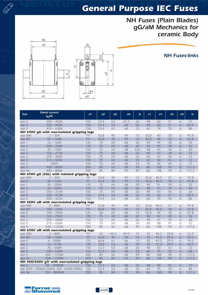
SizeRated current
a1 a2 a3 a4 b c1 e1 e2 e4 hIN(A)
General Purpose IEC Fuses General Purpose IEC Fuses
GPEU33
NH Fuses (Plain Blades)gG/aM Mechanics for
ceramic Body
NH Fuses-links
07/05
size 2 300 – 400A 150 73,4 63 67,2 26 48 60 51 6 72size 3 250 – 400A 150 73,4 63 68 26 60 60 51 6 83,5size 3 425 – 630A 150 73,4 63 68 33 60 74 70 6 86NH 690V gG with non-isolated gripping lugssize 000 2 – 35A 79 53,8 45 49 15 35,8 40 20 6 47,8size 00 40 – 100A 79 53,8 45 49 15 35,8 48 30 6 47,8size 1 16 – 160A 135 75 64 68 20 40 44 30 6 52size 1 200 – 250A 135 75 64 68 20 40 47 39 6 52size 2 35 – 100A 150 75 64 68 626 48 44 30 6 60size 2 125 – 315A 150 75 64 68 26 60 47 39 6 72size 3 250 – 300A 150 75 64 68 26 60 47 39 6 72size 3 315 – 425A 150 75 64 68 33 60 58 51 6 72size 3 500A 150 75 64 68 33 70 64 64 6 72size 4 400 – 800A 200 85 62 68 49 86 108 90 8 117,5size 4a 400 – 800A 200 85 84 90 49 86 108 90 6 117,5NH 690V gG (SGL) with isolated gripping lugssize 000 2 – 35A 79 53,8 45 49 15 35,8 40,5 21 6 47,8size 0 40 – 125A 79 53,8 45 49 15 35,8 40,5 30 6 47,8size 1 35 – 200A 135 75 64 68 20 40 51 39 6 52size 2 32 – 200A 150 75 64 68 26 48 51 39 6 60size 2 250 – 315A 150 75 64 68 26 48 60 46 6 60size 3 250 – 315A 150 73,4 63 68 26 60 60 51 6 83,5size 3 350 – 425A 150 73,4 63 68 33 60 74 70 6 86NH 500V aM with non-isolated gripping lugssize 000 2 – 80A 79 53,8 45 49 15 35,8 40,5 21 6 47,8size 00 100 – 160A 79 53,8 45 49 15 35,8 40,5 30 6 47,8size 0 100 – 200A 125 68 64 68 15 35,8 44 30 6 47,8size 1 160 – 250A 135 75 64 68 20 40 47 39 6 52size 2 250 – 500A 150 75 64 68 26 48 47 39 6 60size 3 315 – 630A 150 75 64 68 33 60 58 51 6 72size 4 630 – 1250A 200 85 62 68 49 86 108 90 8 117,5NH 690V aM with non-isolated gripping lugssize 000 2 – 80A 79 52 45,5 49,5 15 35 40,5 20,8 6 52,5size 00 50 – 160A 79 52,8 45 50 15 35 47,5 29,5 6 59,5size 0 6 – 200A 125 66,8 61 66 15 35 47,5 29,5 6 59,5size 1 16 – 315A 135 70,8 63 68 20 40 52,5 39,5 6 64,5size 2 35 – 500A 150 72,3 63 68 26 48 60 51 6 72size 3 250 – 630A 150 72,3 63 68 33 60 74 70 6 86size 4 400 – 1250A 200 85 62 68 49 86 108 90 8 117,5size 4a 500 – 1250A 200 85 84 90 49 86 108 90 6 117,5NH 400/500V gTr with non-isolated gripping lugssize 2 50 – 250kVA 150 72,3 63 68 26 48 60 51 6 72size 3250 – 400kVA (500V), 500 - 630VA (400V) 150 72,3 63 68 33 60 74 70 6 86size 4a 100 – 800kVA 200 85 84 90 49 86 108 90 6 117,5
General Purpose IEC Fuses General Purpose IEC Fuses
GPEU34
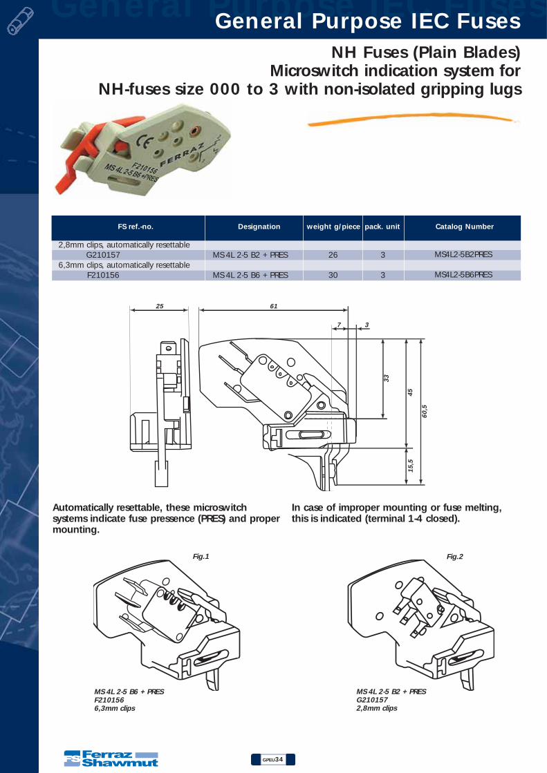
FS ref.-no. Designation weight g/piece pack. unit Catalog Number
2,8mm clips, automatically resettableG210157 MS 4L 2-5 B2 + PRES 26 3
6,3mm clips, automatically resettableF210156 MS 4L 2-5 B6 + PRES 30 3
Automatically resettable, these microswitchsystems indicate fuse pressence (PRES) and propermounting.
In case of improper mounting or fuse melting,this is indicated (terminal 1-4 closed).
MS 4L 2-5 B6 + PRESF2101566,3mm clips
MS 4L 2-5 B2 + PRESG2101572,8mm clips
Fig.1 Fig.2
25 61
7 3
60
,5
45
15
,5
33
MS4L2-5B2PRES
MS4L2-5B6PRES
NH Fuses (Plain Blades)Microswitch indication system for
NH-fuses size 000 to 3 with non-isolated gripping lugs

General Purpose IEC Fuses General Purpose IEC Fuses
GPEU36
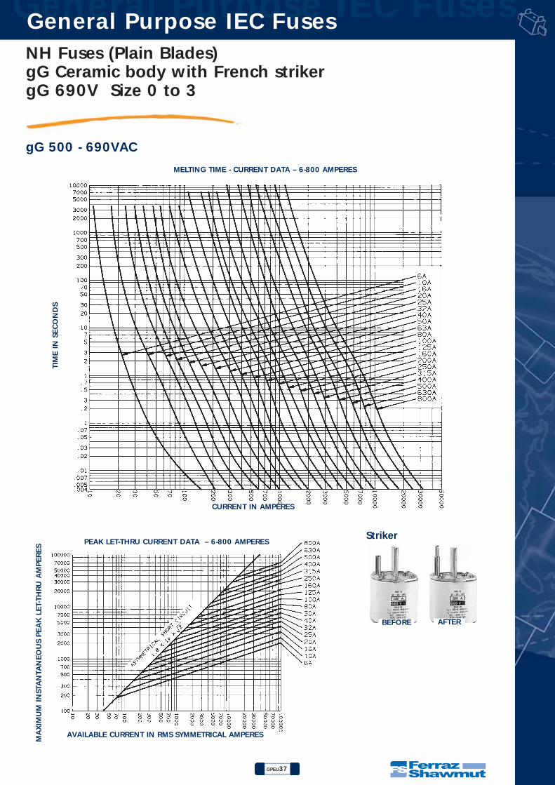
NH Fuses (Plain Blades)gG Ceramic body with French striker
gG 690V Size 0 to 3
gG 500 - 690VAC
07/05
R223000
X214656
N219271
H216690
Size Rated current Rated voltagePrevious ref. Ref.-no.
BreakingCatalog Number
IN(A) (V) capacity
0 32 690V 36443 P213637 80kA - 690V0 35 690V 36445 S214146 80kA - 690V0 40 690V 36447 W214655 80kA - 690V0 50 690V 36451 B215166 80kA - 690V0 63 690V 36455 D215674 80kA - 690V0 80 690V 36459 J216185 80kA - 690V0 100 690V 36463 H216690 80kA - 690V0 125 500V 36465 V217207 120kA - 500V0 160 500V 36469 A217718 120kA - 500V0 200 500V 36471 K218233 120kA - 500V1 80 690V 36559 Y218751 80kA - 690V1 100 690V 36563 M219270 80kA - 690V1 125 690V 36565 P219801 80kA - 690V1 160 690V 36569 Z222478 80kA - 690V1 200 690V 36571 R223000 80kA - 690V1 224 500V 36573 Y200788 120kA - 500V1 250 500V 36575 Q201333 120kA - 500V1 315 500V 36579 Z201847 120kA - 500V1 355 500V 36581 W211067 120kA - 500V2 125 690V 36665 W212102 80kA - 690V2 160 690V 36669 L212622 80kA - 690V2 200 690V 36671 Y213139 80kA - 690V2 224 690V 36673 Q213638 80kA - 690V2 250 690V 36675 T214147 80kA - 690V2 315 690V 36679 X214656 80kA - 690V2 355 500V 36681 E215675 120kA - 500V2 400 500V 36683 K216186 120kA - 500V2 500 500V 36687 W217208 120kA - 500V3 315 690V 36779 B217719 80kA - 690V3 355 690V 36781 L218234 80kA - 690V3 400 690V 36783 Z218752 80kA - 690V3 500 690V 36787 N219271 80kA - 690V3 630 500V 36789 Q219802 120kA - 500V
Dimensions0 1 2 3
A 124.5 134.5 150 150B 66 67 67 67C 39 40 56 69D 49 55 62.5 76E 14.5 16 19 24F 15.5 15.5 15.5 15.5G 14 14.5 14.5 14.5H 15 20 26 32I 6 6 6 6J 14 14 15 16K 10 10 10 10L 59 65 72.5 86M 60 61 61 61N 3 3 3 3O 41.5 45 - -P 47 52 60 60
Pack. : 3 pieces
NH0GG69V32P-2NH0GG69V35P-2NH0GG69V40P-2NH0GG69V50P-2NH0GG69V63P-2NH0GG69V80P-2NH0GG69V100P-2NH0GG50V125P-2NH0GG50V160-2NH0GG50V200P-2NH1GG69V80P-2NH1GG69V100P-2NH1GG69V125P-2NH1GG69V160P-2NH1GG69V200P-2NH1GG50V224P-2NH1GG50V250P-2NH1GG50V315P-2NH1GG50V355P-2NH2GG69V125P-2NH2GG69V160P-2NH2GG69V200P-2NH2GG69V224P-2NH2GG69V250P-2NH2GG69V315P-2NH2GG69V355P-2NH2GG50V400P-2NH2GG50V500P-2NH3GG69V315P-2NH3GG69V355P-2NH3GG69V400P-2NH3GG69V500P-2NH3GG50V630P-2
NH Fuses (Plain Blades)gG Ceramic body with French striker gG 690V Size 0 to 3
GPEU37
General Purpose IEC Fuses General Purpose IEC Fuses
gG 500 - 690VAC
MELTING TIME - CURRENT DATA – 6-800 AMPERES
CURRENT IN AMPERES
TIM
E I
N S
EC
ON
DS
PEAK LET-THRU CURRENT DATA – 6-800 AMPERES
AVAILABLE CURRENT IN RMS SYMMETRICAL AMPERES
MA
XIM
UM
IN
STA
NTA
NEO
US
PEA
K L
ET-
THRU
AM
PERES
Striker
BEFORE AFTER

General Purpose IEC Fuses General Purpose IEC Fuses
GPEU38
NH Fuses (Plain Blades)gG Ceramic body with French striker
gG 690V Size 0 to 3
gG 500 - 690VAC
Rated current SizeIN(A) 0 1 2 3
32 3.7 W35 4.0 W40 4.5 W50 5.2 W63 6.2 W80 7.5 W 6.9 W
100 8.5 W 8.1 W125 10.7 W 9.6 W 9.5 W160 13.5 W 11.9 W 11.5 W200 15.0 W 14.9 W 14.5 W224 16.7 W 16.0 W250 18.7 W 17.5 W315 25.0 W 23.0 W 23 W355 28.0 W 25.0 W 25 W400 29.0 W 29 W425 34.0 W 34 W500 39.0 W 39 W630 47 W800 67 W
Power Loss (Watts) at Rated Current
Rated current 0 1 2 3IN(A) 160A 250A 400A 630A
VDE 0660 (500V) 25 W 32 W 45 W 60 WIEC 269-2-1 (660V) 25 W 32 W 45 W 60 WUNE 21103 (500V) 25 W 32 W 45 W 60 WNFC 63210 (500V) 25 W 32 W 45 W 60 WVDE 0636 (660V) - 23 W 34 W 48 WVDE 0636 (500V) 16 W 23 W 34 W 48 WIEC 269 (500V) 16 W 23 W 34 W 48 WUNESA (500V) 17 W 26 W 32 W 48 WWDE W (500V) 16 W 21 W 32 W 42 W
Typical values allowed by the standards

NH Fuses (Plain Blades)gG Ceramic body with French striker gG 690V Size 0 to 3
GPEU39
General Purpose IEC Fuses General Purpose IEC Fuses
gG 500 - 690VAC
I2T CHARACTERISTICS – DISCRIMINATION
I2T
(AM
PERE
2SE
CO
ND
S)
FUSE-LINK RATED CURRENT IN (A)
_ _ _ 660V
_ _ _ 500V Operating I2t
_ _ _ 380V
_ _ _ Pre-arcing I2t

General Purpose IEC Fuses General Purpose IEC Fuses
GPEU40
NH Fuses (Plain Blades)aM Ceramic body with French striker
aM 690V Size 0 to 3
aM 500 - 690VAC
SizeRated current Rated voltage
Previous ref. Ref.-no.Breaking
Catalog NumberIN(A) (V) capacity
0 32 690V 37443 Z213140 80kA - 690V0 40 690V 37447 R213639 80kA - 690V0 50 690V 37451 V214148 80kA - 690V0 63 690V 37455 Y214657 80kA - 690V0 80 690V 37459 C215167 80kA - 690V0 100 690V 37463 F215676 80kA - 690V0 125 690V 37465 L216187 80kA - 690V0 160 690V 37469 J216691 80kA - 690V0 200 500V 37471 X217209 120kA - 500V1 80 690V 37559 C217720 80kA - 690V1 100 690V 37563 M218235 80kA - 690V1 125 690V 37565 A218753 80kA - 690V1 160 690V 37569 P219272 80kA - 690V1 200 690V 37571 B222480 80kA - 690V1 250 690V 37575 T223002 80kA - 690V1 315 500V 37579 A200790 120kA - 500V2 125 690V 37665 S201335 80kA - 690V2 160 690V 37669 B201849 80kA - 690V2 200 690V 37671 Y211069 80kA - 690V2 224 690V 37673 P211590 80kA - 690V2 250 690V 37675 Y212104 80kA - 690V2 315 690V 37679 N212624 80kA - 690V2 355 690V 37681 A213141 80kA - 690V2 400 690V 37683 S213640 80kA - 690V2 500 500V 37687 W214149 120kA - 500V3 315 690V 37779 Z214658 80kA - 690V3 355 690V 37781 D215168 80kA - 690V3 400 690V 37783 G215677 80kA - 690V3 500 690V 37787 M216188 80kA - 690V3 630 500V 37789 K216692 120kA - 500V
Dimensions
0 1 2 3A 124.5 134.5 150 150B 66 67 67 67C 39 40 56 69D 49 55 62.5 76E 14.5 16 19 24F 15.5 15.5 15.5 15.5G 14 14.5 14.5 14.5H 15 20 26 32I 6 6 6 6J 14 14 15 16K 10 10 10 10L 59 65 72.5 86M 60 61 61 61N 3 3 3 3O 41.5 45 - -P 47 52 60 60
Y212104
M216188
P219272
L216187
Pack. : 3 pieces
NH0AM69V32P-2NH0AM69V40P-2NH0AM69V50P-2NH0AM69V63P-2NH0AM69V80P-2NH0AM69V100P-2NH0AM69V125P-2NH0AM69V160P-2NH0AM50V200P-2NH1AM69V80P-2NH1AM69V100P-2NH1AM69V125P-2NH1AM69V160P-2NH1AM69V200P-2NH1AM69V250P-2NH1AM50V315P-2NH2AM69V125-2NH2AM69V160-2NH2AM69V200-2NH2AM69V224P-2NH2AM69V250-2NH2AM69V315P-2NH2AM69V355-2NH2AM69V400-2NH2AM50V500-2NH3AM69V315P-2NH3AM69V355P-2NH3AM69V400P-2NH3AM69V500P-2NH3AM50V630P-2

NH Fuses (Plain Blades)aM Ceramic body with French striker aM 690V Size 0 to 3
GPEU41
General Purpose IEC Fuses General Purpose IEC Fuses
aM 500 - 690VACMELTING TIME - CURRENT DATA – 32-630 AMPERES
CURRENT IN AMPERES
TIM
E I
N S
EC
ON
DS
PEAK LET-THRU CURRENT DATA – 32-630 AMPERES
AVAILABLE CURRENT IN RMS SYMMETRICAL AMPERES
MA
XIM
UM
IN
STA
NTA
NEO
US
PEA
K L
ET-
THRU
AM
PERES

General Purpose IEC Fuses General Purpose IEC Fuses
GPEU42
NH Fuses (Plain Blades)aM Ceramic body with French striker
aM 690V Size 0 to 3
aM 500 - 690VAC
Rated current SizeIN(A) 0 1 2 3
32 2.4 W40 2.8 W50 3.6 W63 4.6 W80 6.0 W 6.0 W
100 7.5 W 7.5 W125 9.5 W 9.9 W160 12.0 W 12.7 W 12.7 W200 16.4 W 16.4 W224 18.7 W 18.7 W250 21.5 W 21.5 W315 29.0 W 25.0 W355 32.0 W 29.0 W400 34.0 W 34.0 W425 38.5 W500 45.0 W630 60.0 W
Power Loss (Watts) at Rated Current
I2T CHARACTERISTICS – DISCRIMINATION
I2T
(AM
PERE
2SE
CO
ND
S)
FUSE-LINK RATED CURRENT IN (A)
_ _ _ 660V
_ _ _ 500V Operating I2t
_ _ _ 380V
_ _ _ Pre-arcing I2t

General Purpose IEC Fuses General Purpose IEC Fuses
GPEU44
NH Fuses (Plain Blades)gG Plastic body with/without French striker
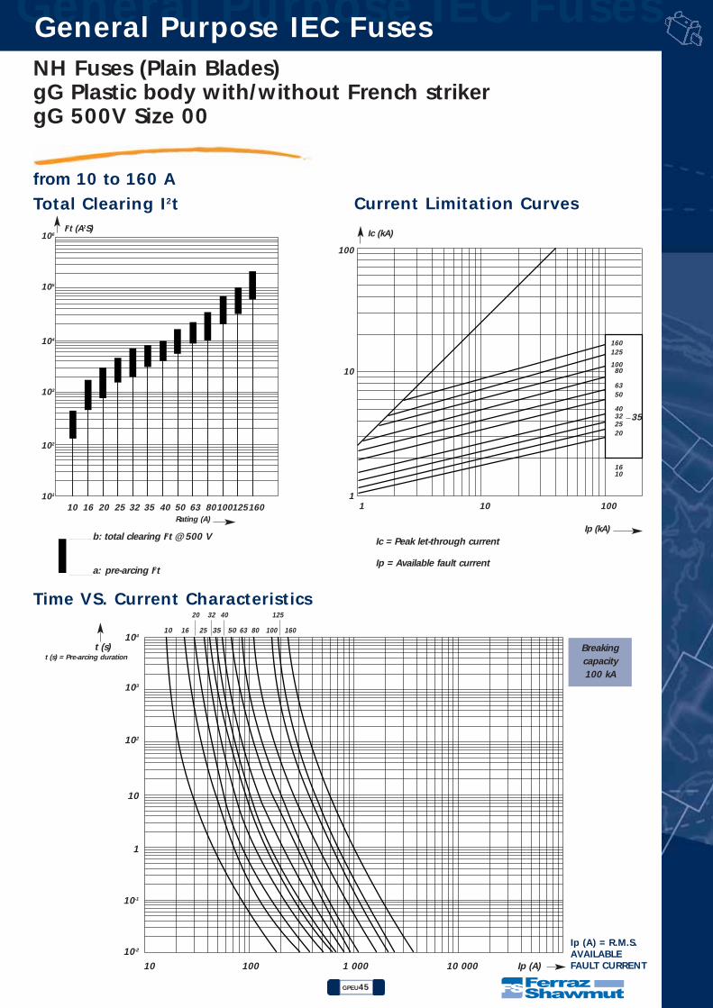
gG 500V Size 00
from 10 to 160 A
Main Characteristics
• BLADE-STYLE FUSES: WITH BLOWN FUSE INDICATOR
• COMPLYING WITH IEC 269.1 and 2.1 NF EN 60269.1 & 2 NF C 63210 AND DIN 43620 STANDARDS
• DIMENSIONS:
00 500
gG 00 L / 10gG 00 L / 16gG 00 L / 20gG 00 L / 25gG 00 L / 32gG 00 L / 35gG 00 L / 40gG 00 L / 50gG 00 L / 63gG 00 L / 80
gG 00 L / 100gG 00 L / 125gG 00 L / 160
M098290N098291P098292Q098293R098294S098295T098296V098297X098299Z098301A098302B098303D098305
Wattsloss(W) Designation Reference Number Catalog Number
11.41.82.133
3.34.567
7.51315
10162025323540506380
100125160
Size
Voltage
rating(VAC)
CurrentratingIN(A)
With BLOWN FUSE indicator
78
14.5
522.5
44
30
461559
10
6
Accessories: Neutral link Z218269Pull-out handle - PMP - Part # P215592
Weight: 150 g
NH00GG50V10-3NH00GG50V16-3NH00GG50V20-3NH00GG50V25-3NH00GG50V32-3NH00GG50V35-3NH00GG50V40-3NH00GG50V50-3NH00GG50V63-3NH00GG50V80-3
NH00GG50V100-3NH00GG50V125-3NH00GG50V160-3
NH Fuses (Plain Blades)gG Plastic body with/without French strikergG 500V Size 00
GPEU45
General Purpose IEC Fuses General Purpose IEC Fuses
from 10 to 160 A
Rating (A)
102
103
104
105
106
101
40353225201610 50 63 80100125160
I2t (A2S)
1 10 100
Ip (kA)
1
10
100
Ic (kA)
Ic = Peak let-through current
Ip = Available fault current
b: total clearing I2t @ 500 V
a: pre-arcing I2t
160125
10080
6350
40322520
1610
10 100 1 000 10 000 Ip (A)
10-1
10-2
1
10
102
103
104
t (s)
Ip (A) = R.M.S.AVAILABLEFAULT CURRENT
t (s) = Pre-arcing duration
10 16 25 35 50 63 80 100 160
12520 32 40
Breakingcapacity 100 kA
35
Total Clearing I2t
Time VS. Current Characteristics
Current Limitation Curves

General Purpose IEC Fuses General Purpose IEC Fuses
GPEU46
NH Fuses (Plain Blades)gG Plastic body with/without French striker
gG 500V Size 0 and 1
from 40 to 250 A
• BLADE-STYLE FUSES: WITH BLOWN FUSE INDICATOR or TRIP-INDICATOR
• COMPLYING WITH IEC 269.1 AND 2.1 NF EN 60269.1 & 2 NF C 63210 - 63211 AND DIN 43620
• DIMENSIONS:
0
1
500
500
gG 0 / 40gG 0 / 50gG 0 / 63gG 0 / 80
gG 0 / 100gG 0 / 125gG 0 / 160gG 0 / 200gG 1 / 80
gG 1 / 100gG 1 / 125gG 1 / 160gG 1 / 200gG 1 / 250
A095013B095014C095015D095016E095017F095018G095019H095020K095022P095026T095030V095031W095032Z095035
T095214V095215W095216Y095218A095220C095222G095226
D095591E095592F095593G095594H095595K095597
Wattsloss(W) Designation Ref. Number Catalog Number
4.25.56.58.59.51215198.59.6
12.5151923
40506380
10012516020080
100125160200250
SizeVoltagerating(VAC)
CurrentratingIN(A)
gG 0 / 40 PgG 0 / 50 PgG 0 / 63 PgG 0 / 80 P
gG 0 / 100 PgG 0 / 125 PgG 0 / 160 P
gG 1 / 80 PgG 1 / 100 PgG 1 / 125 PgG 1 / 160 PgG 1 / 200 PgG 1 / 250 P
Designation Ref. Number
With blown fuse indicator With trip-indicator
LN
DG
B
F
D1
AKH C
J
D2M
e
LN
DG
B
D1
AH C
J
M
e
Size A B C D D1 D2* F* G H J K L M N e Wgt.0 46 62 59 67 36 39 14 2,5 15 14,5 14,5 125 10 14,5 6 230g1 52 64 64 74 47 47 14 3 21 16 14,5 135 10 14,5 6 400g
With trip-indicator With blown fuse indicator
Accessories: Neutral link Reference Number Z219304 - Reference Number A219834Pull-out handle - PMP Reference Number P215592
* For fuses with trip-indicator
NH0GG50V40-4NH0GG50V50-4NH0GG50V63-4NH0GG50V80-4
NH0GG50V100-4NH0GG50V125-4NH0GG50V160-4
NH1GG50V80-4NH1GG50V100-4NH1GG50V125-4NH1GG50V160-4NH1GG50V200-4NH1GG50V250-4
Catalog Number
NH0GG50V40-3NH0GG50V50-3NH0GG50V63-3NH0GG50V80-3
NH0GG50V100-3NH0GG50V125-3NH0GG50V160-3NH0GG50V200-3NH1GG50V80-3
NH1GG50V100-3NH1GG50V125-3NH1GG50V160-3NH1GG50V200-3NH1GG50V250-3

NH Fuses (Plain Blades)gG Plastic body with/without French strikergG 500V Size 0 and 1
GPEU47
General Purpose IEC Fuses General Purpose IEC Fuses
from 40 to 250 A
Rating (A)
102
103
104
105
106
107
40 50 63 80 100 125 160 200 250
I2t (A2S)
1 10 100
Ip (kA)
1
10
100
Ic (kA)
250200
160125100
80
635040
10 100 1 000 10 000 Ip (A)
40 50 63 80 100 160 250
125 200
Ic = Peak let-through current
Ip = Available fault current
b: total clearing I2t @ 500 V
a: pre-arcing I2t
10-1
10-2
1
10
102
103
104
t (s)t (s) = Pre-arcing duration
Ip (A) = R.M.S.AVAILABLEFAULT CURRENT
Breakingcapacity 100 kA
Total Clearing I2t
Time VS. Current Characteristics
Current Limitation Curves

General Purpose IEC Fuses General Purpose IEC Fuses
GPEU48
NH Fuses (Plain Blades)gG Plastic body with/without French striker
gG 500V Size 2 and 3
from 125 to 630 A
• BLADE-STYLE FUSES: WITH BLOWN FUSE INDICATOR or TRIP-INDICATOR
• COMPLYING WITH IEC 269.1 and 2.1, NF EN 60269.1 & 2 NF C 63210 - 63211 AND DIN 43620
• DIMENSIONS:
LN
DG
B
F
D1
AKH C
J
D2M
e
LN
DG
B
D1
AH C
J
M
e
With trip-indicator With blown fuse indicator
Size A B C D D1 D2* F* G H J K L M N e Wgt.2 60 64 72 74 50 50 14 3 28 19 14,5 150 10 14,5 6 590g3 75 61 88 75 70 64 14 2,5 36 23 14,5 150 10 18 6 850g
* For fuses with trip-indicator
2
3
500
500
gG 2 /125gG 2 /160gG 2 /200gG 2 /250gG 2 /315gG 2 /400gG 3 /315gG 3 /400gG 3 /500gG 3 /630
H095066K095068M095070G095042H095043J095044
W095170V095054W095055X095056
X095033Y095034A095036F095041K095045M095047N095048P095049N095071P095072
Wattsloss(W) Designation Ref. Number Catalog Number
12151923243324333645
125160200250315400315400500630
SizeVoltagerating(VAC)
CurrentratingIN(A)
gG 2 /125 PgG 2 /160 PgG 2 /200 PgG 2 /250 PgG 2 /315 PgG 2 /400 PgG 3 /315 PgG 3 /400 PgG 3 /500 PgG 3 /630 P
Designation Ref. Number
With blown fuse indicator With trip-indicator
Catalog Number
Accessories : Neutral link BS2 Reference Number J097712 - BS3 Reference Number K097713Pull-out handle - PMP Reference Number P215592
NH2GG50V125-3NH2GG50V160-3NH2GG50V200-3NH2GG50V250-3NH2GG50V315-3NH2GG50V400-3NH3GG50V315-3NH3GG50V400-3NH3GG50V500-3NH3GG50V630-3
NH2GG50V125-4NH2GG50V160-4NH2GG50V200-4NH2GG50V250-4NH2GG50V315-4NH2GG50V400-4NH3GG50V315-4NH3GG50V400-4NH3GG50V500-4NH3GG50V630-4
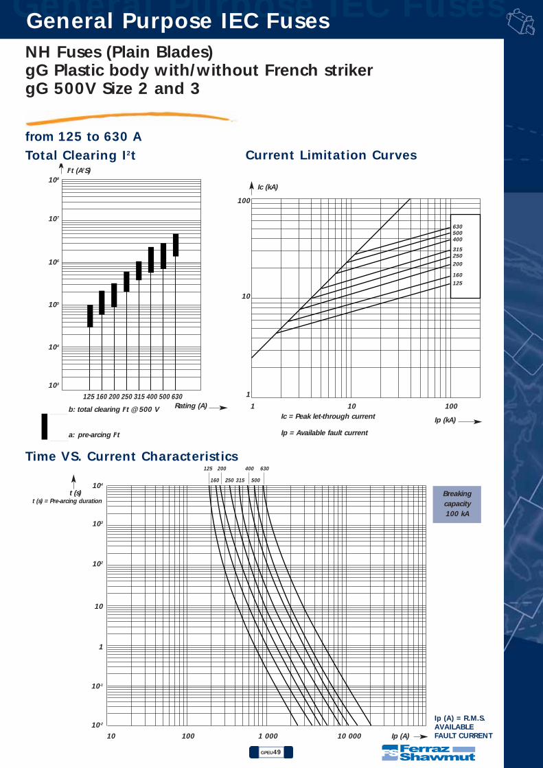
NH Fuses (Plain Blades)gG Plastic body with/without French strikergG 500V Size 2 and 3
GPEU49
General Purpose IEC Fuses General Purpose IEC Fuses
from 125 to 630 A
Rating (A)
103
104
105
106
107
108
125 160 200 250 315 400 500 630
I2t (A2S)
1 10 100
Ip (kA)
1
10
100
Ic (kA)
Ic = Peak let-through current
Ip = Available fault current
b: total clearing I2t @ 500 V
a: pre-arcing I2t
630500400
315250
200
160
125
10 100 1 000 10 000 Ip (A)
10-1
10-2
1
10
102
103
104
t (s)t (s) = Pre-arcing duration
160 250 315 500
125 200 400 630
Ip (A) = R.M.S.AVAILABLEFAULT CURRENT
Breakingcapacity 100 kA
Total Clearing I2t
Time VS. Current Characteristics
Current Limitation Curves

General Purpose IEC Fuses General Purpose IEC Fuses
GPEU50
NH Fuses (Plain Blades)gG Plastic body with/without French striker
gG 500V Size 4
from 630 to 1250 A
• BLADE-STYLE FUSES: WITH BLOWN FUSE INDICATOR or TRIP-INDICATOR
• COMPLYING WITH IEC 269.1 and 2.1, NF EN 60269.1 & 2 NF C 63210 - 63211 AND DIN 43620
• DIMENSIONS:
L
N
DG
150
B
F
D1
AKH C
J
D2M
J
H
e
D1
A C
M
e
L
N
DG
150
B
Accessories: Neutral link - BS4 Reference Number M097715Pull-out handle - PMP Reference Number P215592
With trip-indicator
With blown fuse indicator
Size A B C D D1 D2* F* G H J K L M N e Wgt.4 107 61 119 78 90 77 14 2,5 60 27 14,5 200 10 23 8 1900g
* For fuses with trip-indicator
4 500
gG 4 / 630gG 4 / 800
gG 4 / 1000gG 4 / 1250
S098318T098319V098320W098321
G088510J088512K088513L088514
Wattsloss(W) Designation Ref. Number Catalog Number
45517780
630800
10001250
SizeVoltagerating(VAC)
CurrentratingIN(A)
gG 4 / 630 PgG 4 / 800 PgG 4 / 1000 PgG 4 / 1250 P
Designation Ref. Number
With blown fuse indicator With trip-indicator
Catalog Number
NH4GG50V630-3NH4GG50V800-3NH4GG50V1000-3NH4GG50V1250-3
NH4GG50V630-4NH4GG50V800-4NH4GG50V1000-4NH4GG50V1250-4

NH Fuses (Plain Blades)gG Plastic body with/without French strikergG 500V Size 4
GPEU51
General Purpose IEC Fuses General Purpose IEC Fuses
from 630 to 1250 A
Rating (A)103
104
105
106
107
108
630 800 1000 1250
I2t (A2S)
1 10 100
Ip (kA)
1
10
100
Ic (kA)
Ic = Peak let-through current
Ip = Available fault current
b: total clearing I2t @ 500 V
a: pre-arcing I2t
1250
1000800630
10 100 1 000 10 000 Ip (A)
10-1
10-2
1
10
102
103
104t (s)
t (s) = Pre-arcing duration
630 1000
800 1250
Ip (A) = R.M.S.AVAILABLEFAULT CURRENT
Breakingcapacity 100 kA
Total Clearing I2t
Time VS. Current Characteristics
Current Limitation Curves

General Purpose IEC Fuses General Purpose IEC Fuses
GPEU52
NH Fuses (Plain Blades)aM Plastic body with/without French striker
aM 500V Size 00
from 16 to 125 A
• BLADE-STYLE FUSES: WITH BLOWN FUSE INDICATOR
• COMPLYING WITH IEC 269.1 and 2.1 NF EN 60269.1 & 2 NF C 63210 AND DIN 43620 STANDARDS
• DIMENSIONS:
78
14.5
522.5
44
30
461559
10
6
Weight: 150 g
00500
400
F098307G098308H098309J098310K098311L098312M098313N098314P098315Q098316R098317
Wattsloss(W)
0.81.11.31.82.02.53.03.65.26.07.0
162025323540506380
100125
SizeVoltagerating(VAC)
CurrentratingIN(A)
aM 00 L /16aM 00 L /20aM 00 L /25aM 00 L /32aM 00 L /35aM 00 L /40aM 00 L /50aM 00 L /63aM 00 L /80
aM 00 L /100aM 00 L /125
Designation Ref. Number
With blown fuse indicator
Catalog Number
Accessories: Neutral link BS00 - Reference Number F097709Pull-out handle - PMP - Reference Number P215592
NH00AM50V16-3NH00AM50V20-3NH00AM50V25-3NH00AM50V32-3NH00AM50V35-3NH00AM50V40-3NH00AM50V50-3NH00AM50V63-3NH00AM50V80-3
NH00AM50V100-3NH00AM40V125-3
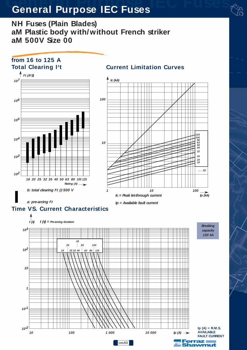
NH Fuses (Plain Blades)aM Plastic body with/without French strikeraM 500V Size 00
GPEU53
General Purpose IEC Fuses General Purpose IEC Fuses
from 16 to 125 A
Rating (A)
103
104
105
106
107
102
403532252016 50 63 80 100 125
I2t (A2S)
1 10 100Ip (kA)
10
100
Ic (kA)
Ic = Peak let-through current
Ip = Available fault current
b: total clearing I2t @ 500 V
a: pre-arcing I2t
125100
80635040
32
252016
10 100 1 000 10 000 Ip (A)
10-1
10-2
1
10
102
103
t (s) t (s) = Pre-arcing duration
16 25 63 80 125
20
32
50
35
100
40
35
Ip (A) = R.M.S.AVAILABLEFAULT CURRENT
Breakingcapacity 100 kA
Total Clearing I2t
Time VS. Current Characteristics
Current Limitation Curves
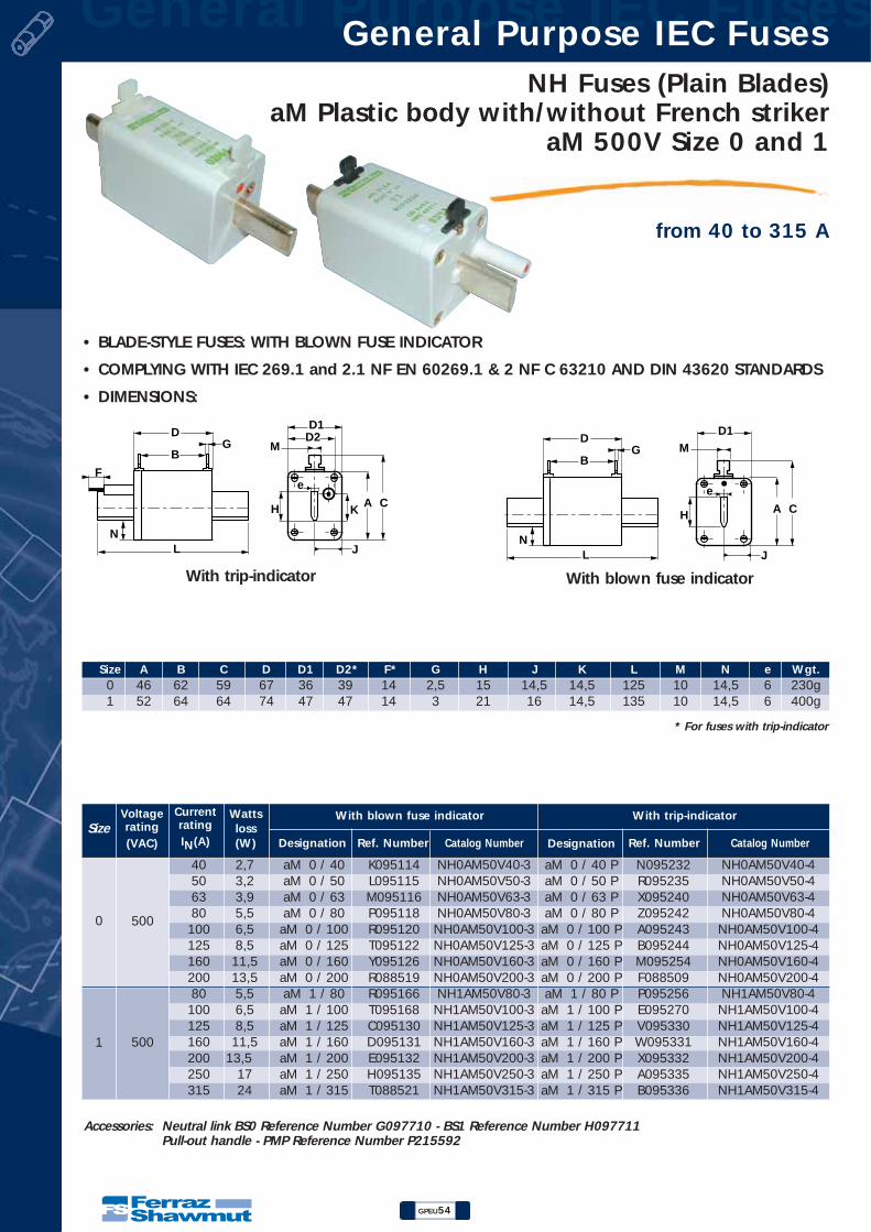
General Purpose IEC Fuses General Purpose IEC Fuses
GPEU54
NH Fuses (Plain Blades)aM Plastic body with/without French striker
aM 500V Size 0 and 1
from 40 to 315 A
• BLADE-STYLE FUSES: WITH BLOWN FUSE INDICATOR
• COMPLYING WITH IEC 269.1 and 2.1 NF EN 60269.1 & 2 NF C 63210 AND DIN 43620 STANDARDS
• DIMENSIONS:
LN
DG
B
F
D1
AKH C
J
D2M
e
LN
DG
B
D1
AH C
J
M
e
Accessories: Neutral link BS0 Reference Number G097710 - BS1 Reference Number H097711Pull-out handle - PMP Reference Number P215592
With trip-indicator With blown fuse indicator
Size A B C D D1 D2* F* G H J K L M N e Wgt.0 46 62 59 67 36 39 14 2,5 15 14,5 14,5 125 10 14,5 6 230g1 52 64 64 74 47 47 14 3 21 16 14,5 135 10 14,5 6 400g
* For fuses with trip-indicator
0
1
500
500
aM 0 / 40aM 0 / 50aM 0 / 63aM 0 / 80
aM 0 / 100aM 0 / 125aM 0 / 160aM 0 / 200aM 1 / 80
aM 1 / 100aM 1 / 125aM 1 / 160aM 1 / 200aM 1 / 250aM 1 / 315
K095114L095115M095116P095118R095120T095122Y095126R088519R095166T095168C095130D095131E095132H095135T088521
N095232R095235X095240Z095242A095243B095244M095254F088509P095256E095270V095330W095331X095332A095335B095336
Wattsloss(W) Designation Ref. Number Catalog Number
2,73,23,95,56,58,5
11,513,55,56,58,5
11,513,5
1724
40506380
10012516020080
100125160200250315
SizeVoltagerating(VAC)
CurrentratingIN(A)
aM 0 / 40 PaM 0 / 50 PaM 0 / 63 PaM 0 / 80 P
aM 0 / 100 PaM 0 / 125 PaM 0 / 160 PaM 0 / 200 PaM 1 / 80 P
aM 1 / 100 PaM 1 / 125 PaM 1 / 160 PaM 1 / 200 PaM 1 / 250 PaM 1 / 315 P
Designation Ref. Number
With blown fuse indicator With trip-indicator
Catalog Number
NH0AM50V40-3NH0AM50V50-3NH0AM50V63-3NH0AM50V80-3
NH0AM50V100-3NH0AM50V125-3NH0AM50V160-3NH0AM50V200-3NH1AM50V80-3
NH1AM50V100-3NH1AM50V125-3NH1AM50V160-3NH1AM50V200-3NH1AM50V250-3NH1AM50V315-3
NH0AM50V40-4NH0AM50V50-4NH0AM50V63-4NH0AM50V80-4
NH0AM50V100-4NH0AM50V125-4NH0AM50V160-4NH0AM50V200-4NH1AM50V80-4
NH1AM50V100-4NH1AM50V125-4NH1AM50V160-4NH1AM50V200-4NH1AM50V250-4NH1AM50V315-4
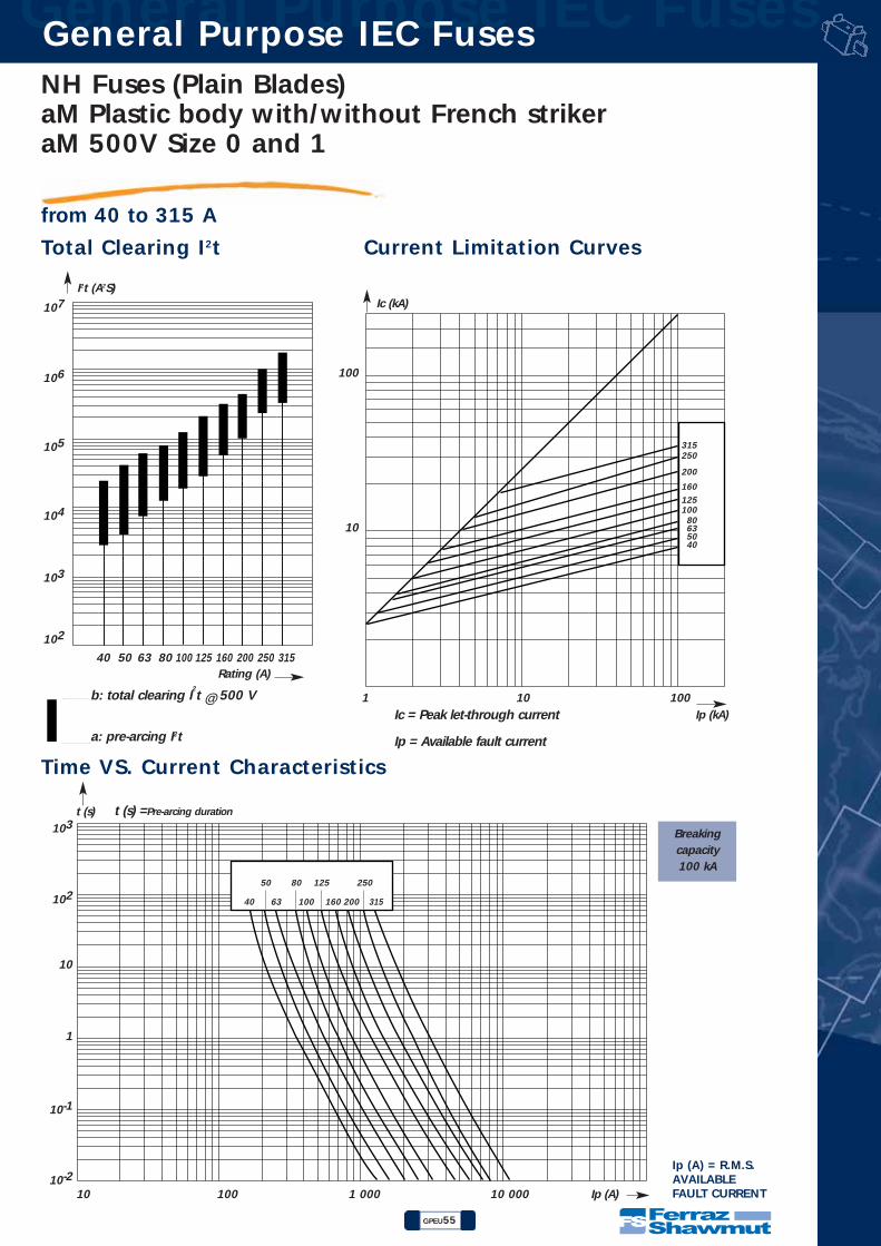
NH Fuses (Plain Blades)aM Plastic body with/without French strikeraM 500V Size 0 and 1
GPEU55
General Purpose IEC Fuses General Purpose IEC Fuses
from 40 to 315 A
Rating (A)
103
104
105
106
107
102
40 50 63 80 100 125 160 200 250 315
I2t (A2S)
1 10 100Ip (kA)
10
100
Ic (kA)
Ic = Peak let-through current
Ip = Available fault current
b: total clearing I2t @ 500 V
a: pre-arcing I2t
315250
200
160
125100
80635040
10 100 1 000 10 000 Ip (A)
10-1
10-2
1
10
102
103t (s) t (s) =Pre-arcing duration
40 63 160 200 315
50 80 125 250
100
Ip (A) = R.M.S.AVAILABLEFAULT CURRENT
Breakingcapacity 100 kA
Total Clearing I2t
Time VS. Current Characteristics
Current Limitation Curves
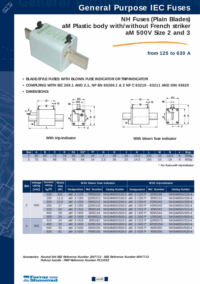
General Purpose IEC Fuses General Purpose IEC Fuses
GPEU56
NH Fuses (Plain Blades)aM Plastic body with/without French striker
aM 500V Size 2 and 3
from 125 to 630 A
• BLADE-STYLE FUSES: WITH BLOWN FUSE INDICATOR OR TRIP-INDICATOR
• COMPLYING WITH IEC 269.1 AND 2.1, NF EN 60269.1 & 2 NF C 63210 - 63211 AND DIN 43620
• DIMENSIONS:
LN
DG
B
F
D1
AKH C
J
D2M
e
LN
DG
B
D1
AH C
J
M
e
Accessories: Neutral link BS2 Reference Number J097712 - BS3 Reference Number K097713Pull-out handle - PMP Reference Number P215592
With trip-indicator With blown fuse indicator
Size A B C D D1 D2* F* G H J K L M N e Wgt.2 60 64 72 74 50 50 14 3 28 19 14,5 150 10 14,5 6 590g3 75 61 88 75 70 64 14 2,5 36 23 14,5 150 10 18 6 850g
* For fuses with trip-indicator
2
3
500
500
aM 2 /125aM 2 /160aM 2 /200aM 2 /250aM 2 /315aM 2 /400aM 2 /500aM 3 /315aM 3 /400aM 3 /500aM 3 /630
P095210Q095211R095212Q095142R095143S095144W088523J095182D095154E095155F095156
Z095196S095213F095340H095342J095343K095344L095345Q095073W095354X095355Y095356
Wattsloss(W) Designation Ref. Number Catalog Number
8,511,513,51724283424283441
125160200250315400500315400500630
SizeVoltagerating(VAC)
CurrentratingIN(A)
aM 2 /125 PaM 2 /160 PaM 2 /200 PaM 2 /250 PaM 2 /315 PaM 2 /400 PaM 2 /500 PaM 3 /315 PaM 3 /400 PaM 3 /500 PaM 3 /630 P
Designation Ref. Number
With blown fuse indicator With trip-indicator
Catalog Number
NH2AM50V125-3NH2AM50V160-3NH2AM50V200-3NH2AM50V250-3NH2AM50V315-3NH2AM50V400-3NH2AM50V500-3NH3AM50V315-3NH3AM50V400-3NH3AM50V500-3NH3AM50V630-3
NH2AM50V125-4NH2AM50V160-4NH2AM50V200-4NH2AM50V250-4NH2AM50V315-4NH2AM50V400-4NH2AM50V500-4NH3AM50V315-4NH3AM50V400-4NH3AM50V500-4NH3AM50V630-4

NH Fuses (Plain Blades)aM Plastic body with/without French strikeraM 500V Size 2 and 3
GPEU57
General Purpose IEC Fuses General Purpose IEC Fuses
from 125 to 630 A
Rating (A)
103
104
105
106
107
108
125 160 200 250 315 400 500 630
I2t (A2S)
b: total clearing I2t @ 500 V
a: pre-arcing I2t
1 10 100Ip (kA)
10
100
Ic (kA)
Ic = Peak let-through current
Ip = Available fault current
630500
400315250
200
160125
10 100 1 000 10 000 Ip (A)
10-1
10-2
1
10
102
103
t (s) t (s) = Pre-arcing duration
160 250 315 500
125 200 400 630
Ip (A) = R.M.S.AVAILABLEFAULT CURRENT
Breakingcapacity 100 kA
Total Clearing I2t
Time VS. Current Characteristics
Current Limitation Curves
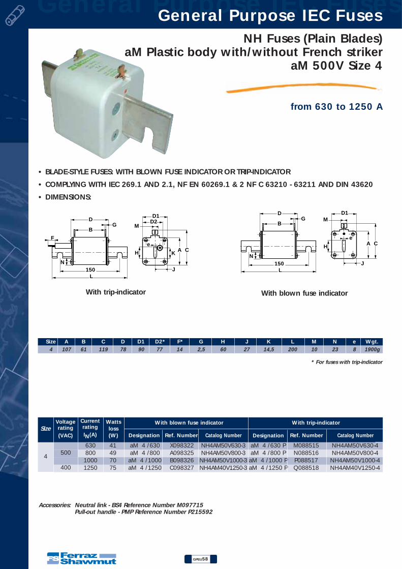
General Purpose IEC Fuses General Purpose IEC Fuses
GPEU58
NH Fuses (Plain Blades)aM Plastic body with/without French striker
aM 500V Size 4
from 630 to 1250 A
L
N
DG
150
B
F
D1
AKH C
J
D2M
e
J
H
e
D1
A C
M
L
N
DG
150
B
Accessories: Neutral link - BS4 Reference Number M097715Pull-out handle - PMP Reference Number P215592
• BLADE-STYLE FUSES: WITH BLOWN FUSE INDICATOR OR TRIP-INDICATOR
• COMPLYING WITH IEC 269.1 AND 2.1, NF EN 60269.1 & 2 NF C 63210 - 63211 AND DIN 43620
• DIMENSIONS:
With trip-indicator With blown fuse indicator
Size A B C D D1 D2* F* G H J K L M N e Wgt.4 107 61 119 78 90 77 14 2,5 60 27 14,5 200 10 23 8 1900g
* For fuses with trip-indicator
4500
400
aM 4 /630aM 4 /800
aM 4 /1000aM 4 /1250
X098322A098325B098326C098327
M088515N088516P088517Q088518
Wattsloss(W) Designation Ref. Number Catalog Number
41497075
630800
10001250
SizeVoltagerating(VAC)
CurrentratingIN(A)
aM 4 /630 PaM 4 /800 P
aM 4 /1000 PaM 4 /1250 P
Designation Ref. Number
With blown fuse indicator With trip-indicator
Catalog Number
NH4AM50V630-3NH4AM50V800-3NH4AM50V1000-3NH4AM40V1250-3
NH4AM50V630-4NH4AM50V800-4
NH4AM50V1000-4NH4AM40V1250-4

NH Fuses (Plain Blades)aM Plastic body with/without French strikeraM 500V Size 4
GPEU59
General Purpose IEC Fuses General Purpose IEC Fuses
from 630 to 1250 A
1 10 100Ip (kA)
10
100
Ic (kA)
Ic = Peak let-through current
Ip = Available fault current
10 100 1 000 10 000 Ip (A)
10-1
10-2
1
10
102
103
t (s) t (s) = Pre-arcing duration
Rating (A)
103
104
105
106
107
108
630 800 1000 1250
I2t (A2S)
b: total clearing I2t @ 500 V
a: pre-arcing I2t
12501000
800630
630 1000
800 1250
Ip (A) = R.M.S.AVAILABLEFAULT CURRENT
Breakingcapacity 100 kA
Total Clearing I2t
Time VS. Current Characteristics
Current Limitation Curves
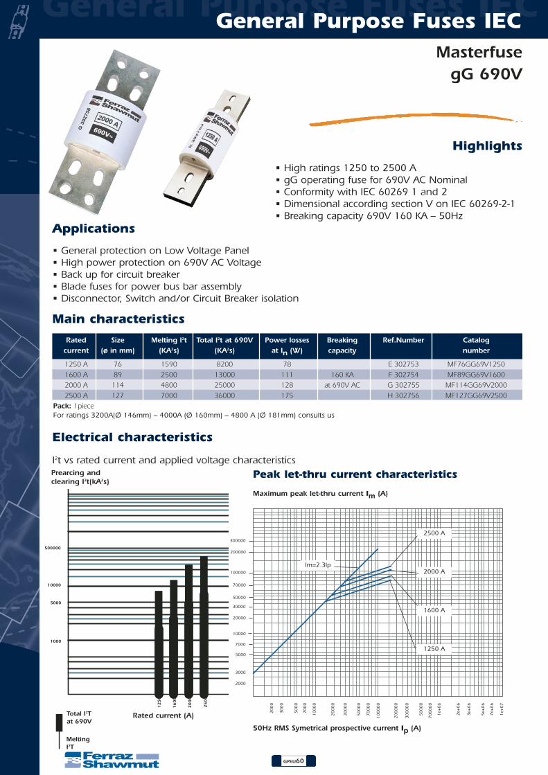
General Purpose Fuses IECGeneral Purpose Fuses IEC
GPEU60
MasterfusegG 690V
Highlights
• High ratings 1250 to 2500 A• gG operating fuse for 690V AC Nominal• Conformity with IEC 60269 1 and 2• Dimensional according section V on IEC 60269-2-1• Breaking capacity 690V 160 KA – 50Hz
Applications
• General protection on Low Voltage Panel• High power protection on 690V AC Voltage• Back up for circuit breaker• Blade fuses for power bus bar assembly• Disconnector, Switch and/or Circuit Breaker isolation
Main characteristics
Electrical characteristics
I2t vs rated current and applied voltage characteristics
Rated Size Melting I2t Total I2t at 690V Power losses Breaking Ref.Number Catalogcurrent (ø in mm) (KA2s) (KA2s) at In (W) capacity number
1250 A 76 1590 8200 78 E 302753 MF76GG69V12501600 A 89 2500 13000 111 160 KA F 302754 MF89GG69V16002000 A 114 4800 25000 128 at 690V AC G 302755 MF114GG69V20002500 A 127 7000 36000 175 H 302756 MF127GG69V2500
Pack: 1pieceFor ratings 3200A(Ø 146mm) – 4000A (Ø 160mm) – 4800 A (Ø 181mm) consults us
500000
10000
5000
1000
12
50
16
00
20
00
25
00
Prearcing and clearing I2t(kA2s)
Maximum peak let-thru current Im (A)
50Hz RMS Symetrical prospective current Ip (A)
Rated current (A)Total I2T at 690V
MeltingI2T
Peak let-thru current characteristics
Im=2.3Ip
2500 A
2000 A
1600 A
1250 A

General Purpose Fuses IECGeneral Purpose Fuses IEC
GPEU61
MasterfusegG 690V
Time current characteristics
0.0002
0.0003
0.00050.0007
0.002
0.003
0.0050.0070.01
0.02
0.03
0.050.070.1
0.2
0.3
0.50.7
1
2
3
57
10
20
30
5070
100
200
300
500700
1000
2000
3000
50007000
10000
0.001
20
00
30
00
50
00
70
00
10
00
0
20
00
0
30
00
0
50
00
0
70
00
0
10
00
00
20
00
00
30
00
00
50
00
00
70
00
00
1 +
06
e
1250 A
1600 A
2000 A
2500 A
Prearcing time (s)
RMS value of prearcing current Ip (A)
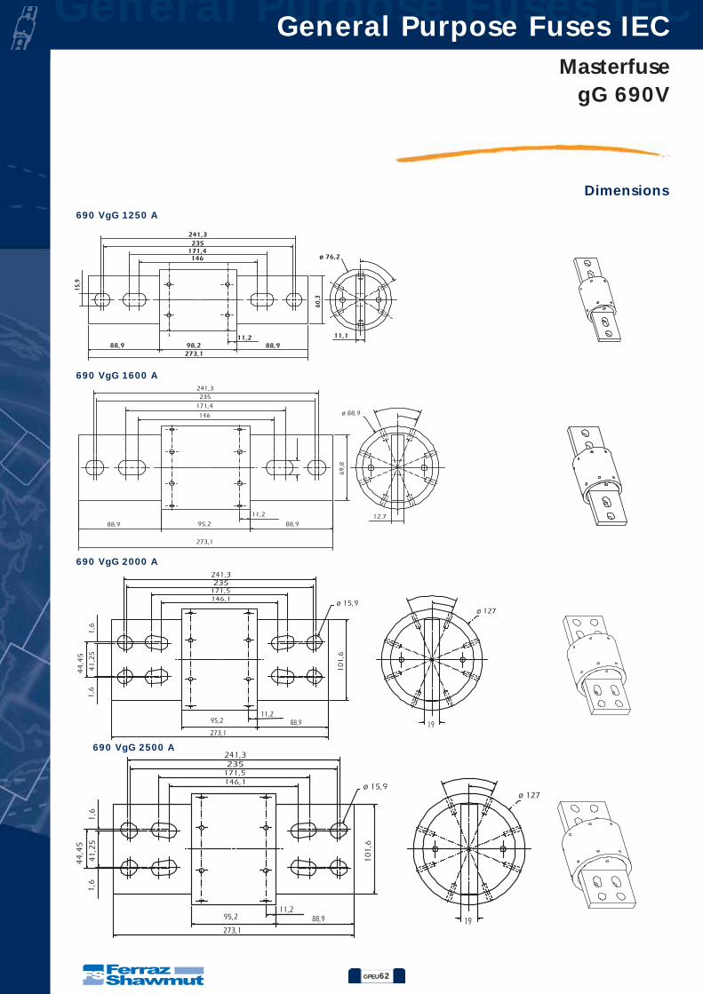
General Purpose Fuses IECGeneral Purpose Fuses IEC
GPEU62
MasterfusegG 690V
690 VgG 1250 A
690 VgG 1600 A
690 VgG 2000 A
690 VgG 2500 A
Dimensions
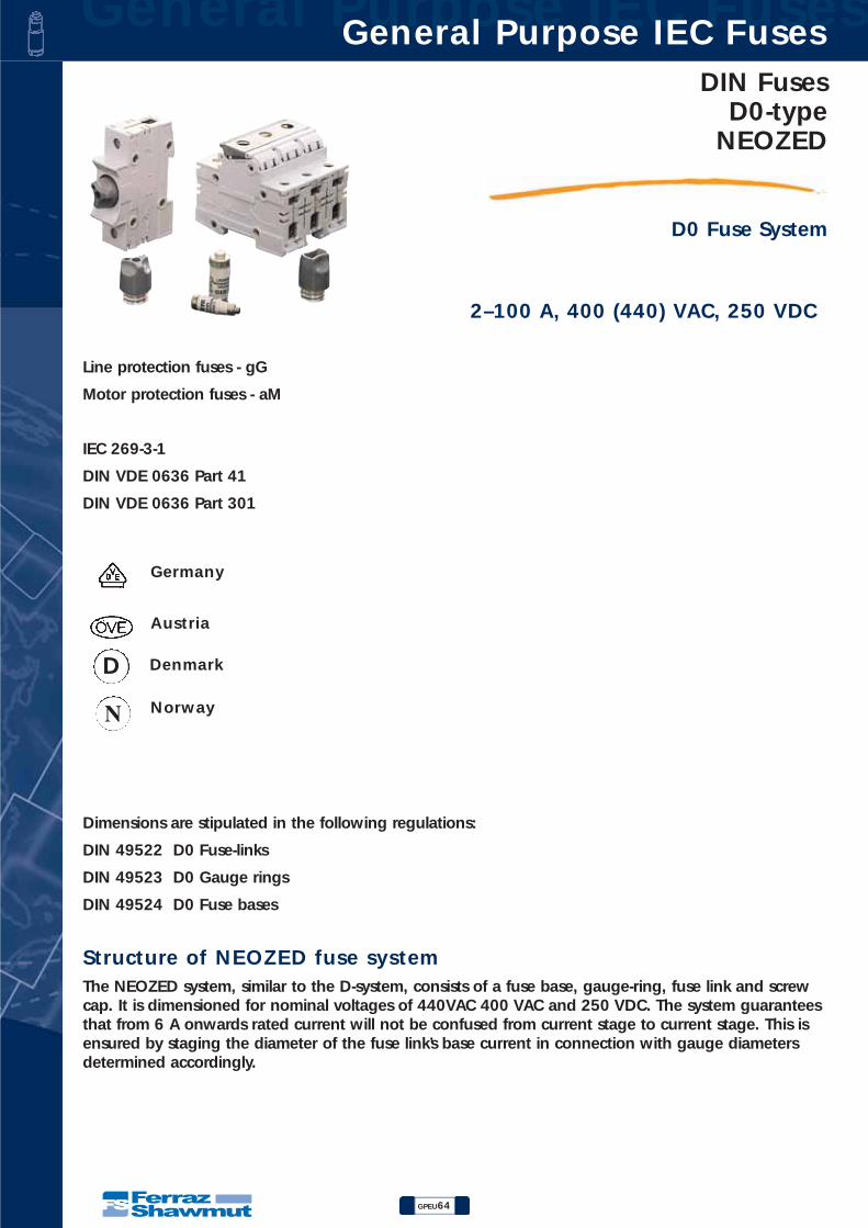
General Purpose IEC Fuses General Purpose IEC Fuses
GPEU64
DIN FusesD0-type
NEOZED
D0 Fuse System
2–100 A, 400 (440) VAC, 250 VDC
Line protection fuses - gG
Motor protection fuses - aM
IEC 269-3-1
DIN VDE 0636 Part 41
DIN VDE 0636 Part 301
Germany
Austria
Norway
DenmarkD
N
Dimensions are stipulated in the following regulations:
DIN 49522 D0 Fuse-links
DIN 49523 D0 Gauge rings
DIN 49524 D0 Fuse bases
Structure of NEOZED fuse systemThe NEOZED system, similar to the D-system, consists of a fuse base, gauge-ring, fuse link and screwcap. It is dimensioned for nominal voltages of 440VAC 400 VAC and 250 VDC. The system guaranteesthat from 6 A onwards rated current will not be confused from current stage to current stage. This isensured by staging the diameter of the fuse link’s base current in connection with gauge diametersdetermined accordingly.

DIN FusesD0-typeNEOZED
GPEU65
General Purpose IEC Fuses General Purpose IEC Fuses
D0 Fuse System
NEOZED Fuse-links 2–100 A gG400 VAC, 250 VDC
Rated in Gauge Previous Reference CatalogSize Current (A) Color Reference Number Pack NumberD01 2 pink 01700.002000 T214676 50
4 brown 01700.004000 W200809 506 green 01700.006000 B215695 50
10 red 01700.010000 W211090 5013 black 01700.013000* C201206* 5016 grey 01700.016000 R223023 50
D02 20 blue 01701.020000 B217742 5025 yellow 01701.025000 W213160 5035 black 01701.035000 R219826 5050 white 01701.050000 D215191 5063 copper 01701.063000 C201873 50
D03 80 silver 01702.080000 L216716 10100 red 01702.100000 N212647 10
*No VDE, ÖVE testing mark
Back-up fuse in operating class gGRated in
Current (A) 20 A 25 A 35 A 50 A 63 A 80 A20 A aM 600 300 200 <100 <100 <10025 A aM - 1500 700 100 <100 <10035 A aM - - 1000 300 200 <100
NEOZED Fuse-links 20–35 A aM400 VAC / 440 VAC
Rated in Gauge Previous Reference CatalogSize Current (A) Color Reference Number Pack NumberD02 20 blue 01701.020500* H211607* 10
25 yellow 01701.025500* F212640* 1035 black 01701.035500* J213655* 10
*No VDE, ÖVE testing markDimensions see following pages
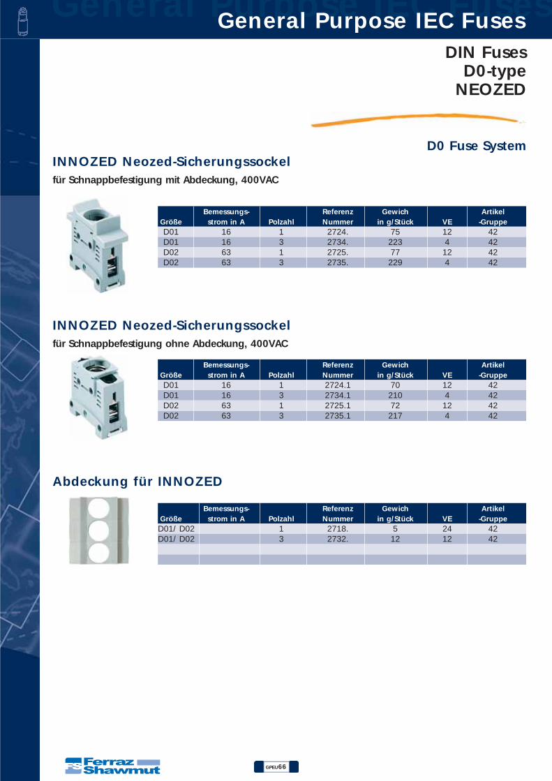
General Purpose IEC Fuses General Purpose IEC Fuses
GPEU66
DIN FusesD0-type
NEOZED
D0 Fuse System
Bemessungs- Referenz Gewich ArtikelGröße strom in A Polzahl Nummer in g/Stück VE -GruppeD01 16 1 2724. 75 12 42D01 16 3 2734. 223 4 42D02 63 1 2725. 77 12 42D02 63 3 2735. 229 4 42
INNOZED Neozed-Sicherungssockelfür Schnappbefestigung mit Abdeckung, 400VAC
Bemessungs- Referenz Gewich ArtikelGröße strom in A Polzahl Nummer in g/Stück VE -GruppeD01 16 1 2724.1 70 12 42D01 16 3 2734.1 210 4 42D02 63 1 2725.1 72 12 42D02 63 3 2735.1 217 4 42
INNOZED Neozed-Sicherungssockelfür Schnappbefestigung ohne Abdeckung, 400VAC
Bemessungs- Referenz Gewich ArtikelGröße strom in A Polzahl Nummer in g/Stück VE -GruppeD01/ D02 1 2718. 5 24 42D01/ D02 3 2732. 12 12 42
Abdeckung für INNOZED

DIN FusesD0-typeNEOZED
GPEU67
General Purpose IEC Fuses General Purpose IEC Fuses
D0 Fuse SystemNEOZED Screw cap - plastic400 VAC / 440 VAC
Rated in Cap Previous Reference CatalogSize Current (A) Thread Reference Number Pack Number
with testing holeD01 16 E 14 01714.000200 E212501 20D02 63 E 18 01715.000200 P211981 20
for D01 fuse links with adapter springD02 E 18 01715.890200 M214026 20
with sealable hole and testing holeD01 16 E 14 11714.000220 R214536 20D02 63 E 18 11715.000220 S214537 20
without testing holeD02 63 E 18 01715.000000 L206435 20
NEOZED Screw cap - porcelain400 VAC / 440 VAC
Rated in Cap Previous Reference CatalogSize Current (A) Thread Reference Number Pack Number
with testing holeD01 16 E 14 01710.000200 H201211 20D02 63 E 18 01711.000200 T215044 20
without testing holeD03 100 M30 x 2 01712.000200 V215045 20Dimensions see following pages
NEOZED Gauge rings
Rated in Cap Previous Reference CatalogSize Current (A) Thread Reference Number Pack NumberD01 2 pink 01705.002000 J216576 50
4 brown 01705.004000 J219681 506 green 01705.006000 P206438 50
10 red 01705.010000 M213014 50D02 2 pink 01706.002000* K216577* 50
4 brown 01706.004000* S222127* 506 green 01706.006000* R211983* 50
10 red 01706.010000* H216069* 5016 grey 01706.016000* Q218629* 5020 blue 01706.020000 S200668 5025 yellow 01706.025000 R213524 5035 black 01706.035000 J216070 5050 white 01706.050000 R218630 50
D03 80 silver 01707.080000 T200669 25*For use of D01 fuse-links in D02 fuse-basesDimensions see following pages
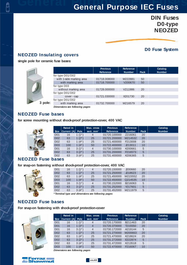
General Purpose IEC Fuses General Purpose IEC Fuses
GPEU68
DIN FusesD0-type
NEOZED
D0 Fuse SystemNEOZED Insulating coverssingle pole for ceramic fuse bases:
3 pole:
Previous Reference CatalogReference Number Pack Number
for type D01/D02with 1-side marking area 01718.008000 M222881 50
with marking area 01718.700000 V200670 50for type D03
without marking area 01728.000000 V211986 20for type D01/D02
cover - cap 01721.030000 X201730 20for type D01/D02
with marking area 01732.700000 M216579 20Dimensions see following pages
NEOZED Fuse basesfor screw mounting without shock-proof protection-cover, 400 VAC
Rated in Max. cross Previous Reference CatalogSize Current (A) Pole sect. mm2 Reference Number Pack NumberD01 16 1 (1*) 4 01720.100000 Z216061 20 D02 63 1 (2*) 25 01721.200000 M214532 20 D02 63 1 (4*) 25 01721.400000 F213008 20 D03 100 1 (4*) 50 01722.400000 J213011 10 D01 16 3 (1*) 4 01730.100000 K200661 5 D02 63 3 (2*) 25 01731.200000 F216573 5 D02 63 3 (4*) 25 01731.400000 K206365 5
D01 16 1 (1*) 4 01720.150000 J200660 20 D02 63 1 (2*) 25 01721.250000 J218623 20 D02 63 1 (4*) 25 01721.450000 W215552 20 D03 100 1 (4*) 50 01722.450000 Q214535 10 D01 16 3 (1*) 4 01730.152000 B216063 5 D02 63 3 (2*) 25 01731.252000 Y217601 5 D02 63 3 (4*) 25 01731.452000 M211979 5
*Terminal type and dimensions see following pages
NEOZED Fuse basesFor snap-on fastening with shock-proof protection-cover
Rated in Max. cross Previous Reference CatalogSize Current (A) Pole sect. mm2 Reference Number Pack NumberD01 16 1 (1*) 4 01720.170000 B211463 20 D01 16 1 (3*) 4 01720.370000 T215550 20 D01 16 3 (1*) 4 01730.172000 A219144 5 D02 63 1 (2*) 25 01721.270000 M200663 20 D02 63 1 (4*) 25 01721.470000 K218624 20 D02 63 3 (2*) 25 01731.272000 E222874 5 D02 63 3 (4*) 25 01731.472000 K213518 5 D03 100 1 (4*) 50 01722.470000 F216067 10
Dimensions see following pages
NEOZED Fuse basesfor snap-on fastening without shock-proof protection-cover, 400 VAC

DIN FusesD0-typeNEOZED
GPEU69
General Purpose IEC Fuses General Purpose IEC Fuses
D0 Fuse SystemLINOZED Fuse basesFor snap-on fastening, 400VAC
Rated in Max. cross Previous Reference CatalogSize Current (A) Pole sect. mm2 Reference Number Pack NumberD01 16 1 35 01724.000000 M217085 6 D02 63 1 35 01725.000000 R215042 6 D01 16 3 35 01734.000000 E201208 2 D02 63 3 35 01735.000000 Y215554 2
Dual function terminals Dimensions see following pages
NEOZED Universal fuse basesfor screw mounting, 400 VAC
Rated in Max. cross Previous Reference CatalogSize Current (A) Pole sect. mm2 Reference Number Pack NumberD01 16 1 (1*) 4 01720.130000 B222871 20 D02 63 1 (2*) 25 01721.230000 D216571 20
63 1 (4*) 25 01721.430000 Q215041 20 D03 100 1 (4*) 50 01722.430000 K214024 10 D01 16 1 (1*) 4 01720.180000 G213515 20 D02 63 1 (2*) 25 01721.280000 L211978 20 D02 63 1 (4*) 25 01721.480000 G213009 20 D03 100 1 (4*) 50 01722.480000 H219680 10
* Terminal type and dimensions see following pages
NEOZED 3-pole fuse baseswithout shock-proof protection, 400 VAC
Rated in Max. cross Previous Reference CatalogSize Current (A) Pole sect. mm2 Reference Number Pack Number
Screw fixingD01 16 3 (1*) 4 01737.100000 A212497 5 D02 63 3 (2*) 25 01738.200000 Z217602 5
Snap-on fasteningD01 16 3 (1*) 4 01737.150000 E213007 5 D02 63 3 (2*) 25 01738.250000 B218110 5
* Terminal type and dimensions see following pages
NEOZED 3-pole fuse baseswithout shock-proof protection, 400 VAC
Rated in Max. cross Previous Reference CatalogSize Current (A) Pole sect. mm2 Reference Number Pack Number
Clamp fixing for busbar 12 x 4…5mm, 15 x4…5 mm D02 63 1 (2*) 25 01746.200801 P222124 20
Clamp fixing for busbar 12 x 4 …10 mm, 15 x 4 …10 mm D02 63 1 (2*) 25 01741.200001 L218625 20
Snap-on fastening for busbar 15 x 5 mm D02 63 1 (2*) 25 01741.250000 G219679 20
* Terminal type and dimensions see following pages
Clamp fixing
Snap-on fastening
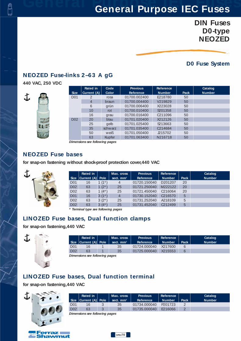
General Purpose IEC Fuses General Purpose IEC Fuses
GPEU70
DIN FusesD0-type
NEOZED
D0 Fuse System
NEOZED Fuse-links 2–63 A gG440 VAC, 250 VDC
Rated in Code Previous Reference CatalogSize Current (A) Color Reference Number Pack NumberD01 2 rosa 01700.002400 E218780 50
4 braun 01700.004400 V219829 50 6 grün 01700.006400 X223028 50
10 rot 01700.010400 S201358 50 16 grau 01700.016400 C211096 50
D02 20 blau 01701.020400 X212126 50 25 gelb 01701.025400 S213663 50 35 schwarz 01701.035400 C214684 50 50 weiß 01701.050400 J215702 50 63 Kupfer 01701.063400 N216718 50
Dimensions see following pages
NEOZED Fuse basesfor snap-on fastening without shock-proof protection cover,440 VAC
Rated in Max. cross Previous Reference CatalogSize Current (A) Pole sect. mm2 Reference Number Pack NumberD01 16 1 (1*) 4 01720.150040 D201207 20 D02 63 1 (2*) 25 01721.250040 M222122 20 D02 63 1 (4*) 25 01721.450040 C216064 20 D01 16 3 (1*) 4 01730.152040 C216570 5 D02 63 3 (2*) 25 01731.252040 A218109 5 D02 63 3 (4*) 25 01731.452040 C212499 5
* Terminal type see following pages
LINOZED Fuse bases, Dual function clampsfor snap-on fastening,440 VAC
Rated in Max. cross Previous Reference CatalogSize Current (A) Pole sect. mm2 Reference Number Pack NumberD01 16 1 35 01724.000040 X217600 6 D02 63 1 35 01725.000040 X215553 6
Dimensions see following pages
LINOZED Fuse bases, Dual function terminalfor snap-on fastening,440 VAC
Rated in Max. cross Previous Reference CatalogSize Current (A) Pole sect. mm2 Reference Number Pack NumberD01 16 3 35 01734.000040 P201723 2 D02 63 3 35 01735.000040 E216066 2
Dimensions see following pages

DIN FusesD0-typeNEOZED
GPEU71
General Purpose IEC Fuses General Purpose IEC Fuses
D0 Fuse System
NEOZED - Special holding spring
Previous Reference CatalogSize Reference Number Pack Number
D01 Fuse-links in D02-socket 01713.000000 Z215049 50 D02 Fuse-links in D03-socket 01709.000000 P214028 10 D01 Fuse-links in DL-socket 01733.000000 J218117 100
NEOZED - Spacer
Previous Reference CatalogSize Reference Number Pack Number
D02 Fuse-links in D03-socket 01707.000000 T211985 10
NEOZED - Gauge ring key
Previous Reference CatalogSize Reference Number Pack Number
gauge-rings D01, D02, D03 01708.000000 J212505 10
NEOZED - Screw-cap remover
Previous Reference CatalogSize Reference Number Pack Number
plastic screw-caps D01, D02 01716.000000 X222936 1 01716.333000 F200726 1
NEOZED - Locking keys
Previous Reference CatalogSize Reference Number Pack Number
D02 Supply boards 01714.820000* K213564 10 D02 Industry 01714.830000 J214069 10
* for authorized energy supplier personnel only
NEOZED - Locking caps
Previous Reference CatalogSize Reference Number Pack Number
D01 supply boards (1) 01714.800000* D212546* 25 D01 Industry (2) 01714.810000 P213062 25
D02 supply boards (1) 01715.800000* R214582* 25 D02 Industry (2) 01715.810000 Y215094 25
* only for authorized energy supplier personnel 1) black top, red screw pitch 2) red top, black screw pitch

General Purpose IEC Fuses General Purpose IEC Fuses
GPEU72
DIN FusesD0-type
NEOZED
D0 Fuse SystemINNOZEDDer Neozed-Sicherungssockel mit innovativer Anschlusstechnik
Kunststoffemit höchsten Ansprüchen
• Sockelabdeckung aus flammwidrigem Polyamid
• Gehäuse aus glasfasergefülltem, duroplastis-chem Polyester
• Hohe mechanische und thermischeBelastbarkeit
Innovative Anschlusstechnikdurch zweigeteilte Rahmenklemme.
• Kontaktierung der Einspeiseleitungen
• Anschluss der Verdrahtungsschienen
• Leitungen leichter einführbar Klemmstellender Leitungen visuell kontrollierbar
• Einsparung von Montagezeit
• Zusätzliche Betriebssicherheit und Flexibilität
VerdrahtungsschienenFolgende Schienen sind einsetzbar:
- 3-phasig 16 mm2 – Ref.Nr. 2963.003
- 1-phasig 16 mm2 – Ref.Nr. 2963.
Flexible KlemmentechnikUnterschiedliche Leiterquerschnitte und Leiterarten sind problemlos klemmbar, sowohl eingangs- alsauch abgangsseitig
• Flexibilität bei der Verdrahtung
• Erhöhung der Betriebssicherheit bei der Klemmung unterschiedlicher Leiter
35mm2 und 4mm2
abgangseitig2 x 16mm2
auf derEinspeiseseite
Zwillingsaderendhülseauf der
Einspeiseseite
35mm2 und 4mm2auf der
Einspeiseseite

DIN FusesD0-typeNEOZED
GPEU73
General Purpose IEC Fuses General Purpose IEC Fuses
D0 Fuse SystemVariabler Berührungsschutz
Geteilte Anschlussklemme zur Klemmung zweier Leitungen
V O R T E I L E des INNOZED• Schnellere Montage• Höhere Betriebssicherheit• Klemmstelle sichtbar vor Verdrahtungsschiene
MIT SOCKELABDECKUNG FÜR VERTEILERBAU
Berührungsschutz durch einfaches Aufrasten derSockelabdeckung.
OHNE SOCKELABDECKUNGIM INDUSTRIELLENANLAGENBAU
Berührungsschutz nach BGVA2 auch ohne ockelabdec-kung bis 25mm2
Anschlussquerschnitt
• Einsparung derMontagezeit und der Kostender Sockelabdeckung
FELDABDECKUNG AUSKUNSTSTOFF
individuell zugeschnitten
• einfach und kostengünstig
Einspeisung Abgang
1. flexible Leitungen mit Aderendhülse zwei Leitungen gleichen Querschnitts: bis max. 10mm2 bis max. 16mm2
zwei unterschiedliche Leitungen: 16mm2 u. max. 10mm2
25mm2 u. max. 6mm2 25mm2 u. max. 6mm2
35mm2 u. max. 4mm2 35mm2 u. max. 4mm2
mit Zwillingsaderendhülse: bis max. 16mm2 bis max. 16mm2
2. flexible, feindrähtige Leitungen ohne Aderendhülse zwei Leitungen gleichen Querschnitts: bis max. 10mm2 bis max. 16mm2
zwei unterschiedliche Leitungen: 16mm2 u. max. 10mm2
25mm2 u. max. 10mm2 25mm2 u. max. 16mm2
35mm2 u. max. 10mm2 5mm2 u. max. 10mm2
3. kurzschlussfeste Leitungen: zwei Leitungen gleichen Querschnitts: bis max. 6mm2 bis max. 6mm2
Maximaler Anschlussquerschnitt der Zu- und Abgangsklemme: 35mm2

VorschriftenIEC 60269-3-1DIN VDE 0636 Teil 301
Prüfzeichen
BaugrößenDrei Baugrößen stehen zur Verfügung:• Sicherungssockel D01
- Gewinde E 14- Nennstrom 16A- für Sicherungseinsätze 2 ... 16A
• Sicherungssockel D02- Gewinde E 18- Nennstrom 63A- für Sicherungseinsätze 20 ... 63A- mit Spezialpasshülsen auch verwendbar für Sicherungseinsätze 2 ... 16A
• Sicherungssockel D03- Gewinde M 30 x 2- Nennstrom 100A- für Sicherungseinsätze 80 und 100A
BetriebsklassenDie Betriebsklasse ist durch zwei Buchstaben gekennzeichnet.Der erste Buchstabe gibt die Funktionsklasse, der zweite das zuschützende Objekt an. Unser Lieferprogramm umfasst NEOZEDSicherungseinsätzenach DIN VDE 0636 für folgende Betriebsklassen:• gG: Ganzbereichskabel- und Leitungsschutz• gR: Ganzbereichs-Halbleiterschutz• aM: Teilbereichs-Schaltgeräteschutz (Motorschutz)
SchaltvermögenNEOZED-Sicherungseinsätze schalten im gesamten Bereich derZeit-Stromkennlinie auch im Bereich der kritischen Ströme zuverlässigab.Das Schaltvermögen ist 50kA.
Klemmrausführunger der keramiksockel
General Purpose IEC Fuses General Purpose IEC Fuses
GPEU74
DIN FusesD0-type
NEOZED
D0 Fuse System
Germany NorwayDenmarkD N
Fig.1 Fig.2 Fig.3 Fig.4

DIN FusesD0-typeNEOZED
GPEU75
General Purpose IEC Fuses General Purpose IEC Fuses
D0 Fuse System
Neozed-Sicherungssockel INNOZED400VAC / 250VDC,D01 (D02), 16A (63A),Berührungsschutz nach BGVA 2 (auch ohneAbdeckung)Abdeckung abnehmbar bei eingeschraubterSicherungMaterial Kunststoff zweigeteilte Rahmenklemmen
Neozed-Sicherungssockel LINOZED400VAC / 250VDCD01 (D02), 16A (63A)Berührungsschutz nach BGVA 2Material KunststoffDoppelfunktionsklemmen gefederter Fußkontakt
Neozed-Sicherungssockel400VAC / 250VDCD01 (D02, D03)16A (63A, 100A)Material KeramikAnschlussart Klemmbügel (Schelle – Schelle,Schraube – Schelle)
Neozed-Sicherungseinsatz400VAC / 250VDCD01 (D02, D03)2 ... 16A (20 ... 63A, 80 ... 100A)Betriebsklasse gG
Neozed-Sicherungseinsatz400VAC / 400VACD02, 20A (25A,35A)Betriebsklasse aM für Schaltgeräteschutz inMotorenstromkreisen
Neozed-Sicherungseinsatz440VACD01 (D02, D03)2 ... 16A (20 ... 63A, 80 ... 100A)Betriebsklasse gR für Halbleiterschutz
Neozed-Schraubkappen400VAC / 250VDCD01 (D02, D03)16A (63A, 100A)Material Kunststoff (Keramik),mit Prüfloch (und Plombierloch)
Neozed-HülsenpasseinsatzD01 (D02, D03)2 ... 10A (20 ... 50A, 80A)Neozed-Spezialhülsenpasseinsatz für D01-Sicherungseinsätze in D02-SicherungssockelnD02, 2 ... 16A
Ausschreibungstexte

General Purpose IEC Fuses General Purpose IEC Fuses
GPEU76
DIN FusesD0-type
NEOZED
D0 Fuse System
2 – 100A, 400 (440)VAC,250VDC Leitungsschutzsicherungen gG
Eigenverbrauch in W
SelektivitätNEOZED-Sicherungseinsätze sind im Verhältnis 1:1,6 der Nennströmemit allen Sicherungseinsätzen selektiv, die folgendenAnforderungen entsprechen:Betriebsklasse gG entspr. lEC 60269-2-1, 60269-3-1Betriebsklasse gG entspr. DIN VDE 0636 Teil 201, 301NEOZED-Sicherungseinsätze sind untereinander und bei gemischtemEinsatz mit Sicherungseinsätzen anderer Lindner-Systeme imVerhältnis 1:1,25 selektiv, d.h. von Nennstromstufe zu Nennstromstufe.Beide Sicherungen sollten jedoch bei so enger Staffelunggleichen Umgebungseinflüssen ausgesetzt sein.
NEOZED-Sicherungseinsätze 32AZur Absicherung von 32A CEE Steckdosen sind entsprechend derneuen DIN VDE 0623 Teil 1/06.93 (DIN EN 60309-1) Sicherungseinsätzemit maximal 32A Bemessungsstrom vorgeschrieben.Bisher durften 32A CEE Steckdosen ausnahmsweise mit 35A abgesichertwerden.Diese Ausnahmeregelung darf zukünftig für Neuanlagen nichtmehr angewendet werden, da die entsprechende Vorschrift DINVDE 0623/03.77 nicht mehr gültig ist. Es gilt jedoch eine Übergangsfristbis 2003-02-01.Passorgane: Es sind die Hülsenpasseinsätze 35A zu verwenden.
Nennstrom in A Größtwerte * Messwerte
2 2,5/2,5 1,5 4 1,8 1,5 6 1,8 1,3
10 2,0 1,8 16 2,5/2,2 2,1 20 3,0/2,5 2,3 25 3,5/3,0 2,6 35 4,0 2,9 50 5,0 3,5 63 5,5 4,2 80 6,5 4,9
100 7,0 5,8

DIN FusesD0-typeNEOZED
GPEU77
General Purpose IEC Fuses General Purpose IEC Fuses
D0 Fuse SystemDirekte Zuordnung bei Schutz von Kabel und Leitungen bei Überlast
Bei der Zuordnung von Überstrom-Schutzorganen zum Kabel- und Leitungsschutz sind nach DIN VDE0100 Teil 430 folgende Bedingungen zu erfüllen:
lB ≤ IN ≤ lZ (Nennstromregel) (1)I2 ≤ 1,45 x lN (Auslöseregel) (2)IB - Betriebsstrom des StromkreisesIN - Nennstrom der ausgewählten ÜberstromeinrichtungIZ - zulässige Strombelastbarkeit des KabelsI2 - Auslösestrom der Schutzeinrichtung
DIN VDE 0636 Teil 301 wurde durch eine Zusatzprüfung "Abschalten mit l2 = 1,45 x IN in der konven-tionellen Prüfdauer" ergänzt.NEOZED-Sicherungseinsätze gG erfüllen die Bedingungen dieser Zusatzprüfung. Damit ist eine direkteZuordnung des Nennstromes des Sicherungseinsatzes zur Belastbarkeit der Leitung oder des Kabelsmöglich.
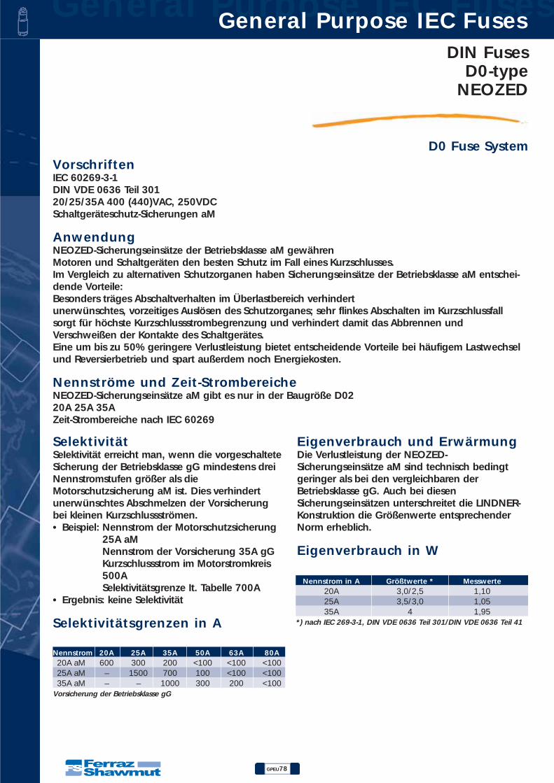
General Purpose IEC Fuses General Purpose IEC Fuses
GPEU78
DIN FusesD0-type
NEOZED
D0 Fuse SystemVorschriftenIEC 60269-3-1DIN VDE 0636 Teil 30120/25/35A 400 (440)VAC, 250VDCSchaltgeräteschutz-Sicherungen aM
AnwendungNEOZED-Sicherungseinsätze der Betriebsklasse aM gewährenMotoren und Schaltgeräten den besten Schutz im Fall eines Kurzschlusses.Im Vergleich zu alternativen Schutzorganen haben Sicherungseinsätze der Betriebsklasse aM entschei-dende Vorteile:Besonders träges Abschaltverhalten im Überlastbereich verhindertunerwünschtes, vorzeitiges Auslösen des Schutzorganes; sehr flinkes Abschalten im Kurzschlussfallsorgt für höchste Kurzschlussstrombegrenzung und verhindert damit das Abbrennen undVerschweißen der Kontakte des Schaltgerätes.Eine um bis zu 50% geringere Verlustleistung bietet entscheidende Vorteile bei häufigem Lastwechselund Reversierbetrieb und spart außerdem noch Energiekosten.
Nennströme und Zeit-StrombereicheNEOZED-Sicherungseinsätze aM gibt es nur in der Baugröße D0220A 25A 35AZeit-Strombereiche nach IEC 60269
SelektivitätSeIektivität erreicht man, wenn die vorgeschalteteSicherung der Betriebsklasse gG mindestens dreiNennstromstufen größer als dieMotorschutzsicherung aM ist. Dies verhindertunerwünschtes Abschmelzen der Vorsicherungbei kleinen Kurzschlussströmen.• Beispiel: Nennstrom der Motorschutzsicherung
25A aMNennstrom der Vorsicherung 35A gGKurzschlussstrom im Motorstromkreis500ASelektivitätsgrenze It. Tabelle 700A
• Ergebnis: keine Selektivität
Selektivitätsgrenzen in A
Eigenverbrauch und ErwärmungDie Verlustleistung der NEOZED-Sicherungseinsätze aM sind technisch bedingtgeringer als bei den vergleichbaren derBetriebsklasse gG. Auch bei diesenSicherungseinsätzen unterschreitet die LINDNER-Konstruktion die Größenwerte entsprechenderNorm erheblich.
Eigenverbrauch in W
Nennstrom 20A 25A 35A 50A 63A 80A20A aM 600 300 200 <100 <100 <100 25A aM – 1500 700 100 <100 <100 35A aM – – 1000 300 200 <100
Vorsicherung der Betriebsklasse gG
Nennstrom in A Größtwerte * Messwerte20A 3,0/2,5 1,10 25A 3,5/3,0 1,05 35A 4 1,95
*) nach IEC 269-3-1, DIN VDE 0636 Teil 301/DIN VDE 0636 Teil 41
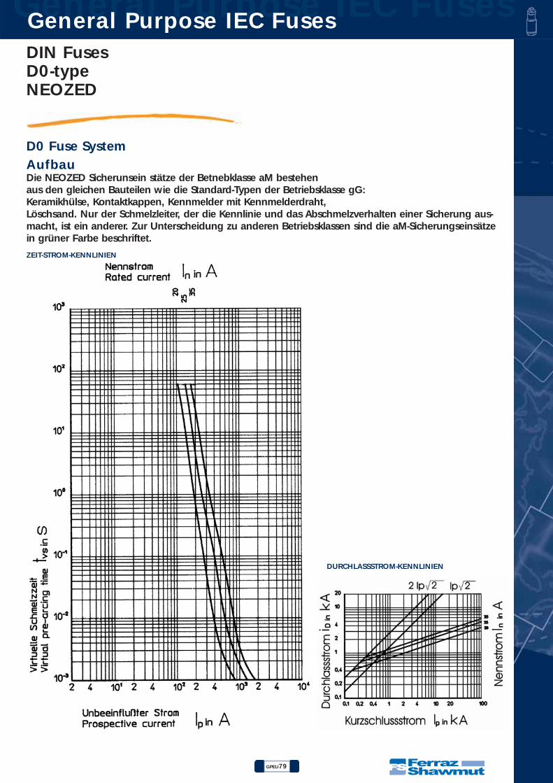
DIN FusesD0-typeNEOZED
GPEU79
General Purpose IEC Fuses General Purpose IEC Fuses
D0 Fuse SystemAufbau Die NEOZED Sicherunsein stätze der Betnebklasse aM bestehenaus den gleichen Bauteilen wie die Standard-Typen der Betriebsklasse gG:Keramikhülse, Kontaktkappen, Kennmelder mit Kennmelderdraht,Löschsand. Nur der Schmelzleiter, der die Kennlinie und das Abschmelzverhalten einer Sicherung aus-macht, ist ein anderer. Zur Unterscheidung zu anderen Betriebsklassen sind die aM-Sicherungseinsätzein grüner Farbe beschriftet.
ZEIT-STROM-KENNLINIEN
DURCHLASSSTROM-KENNLINIEN
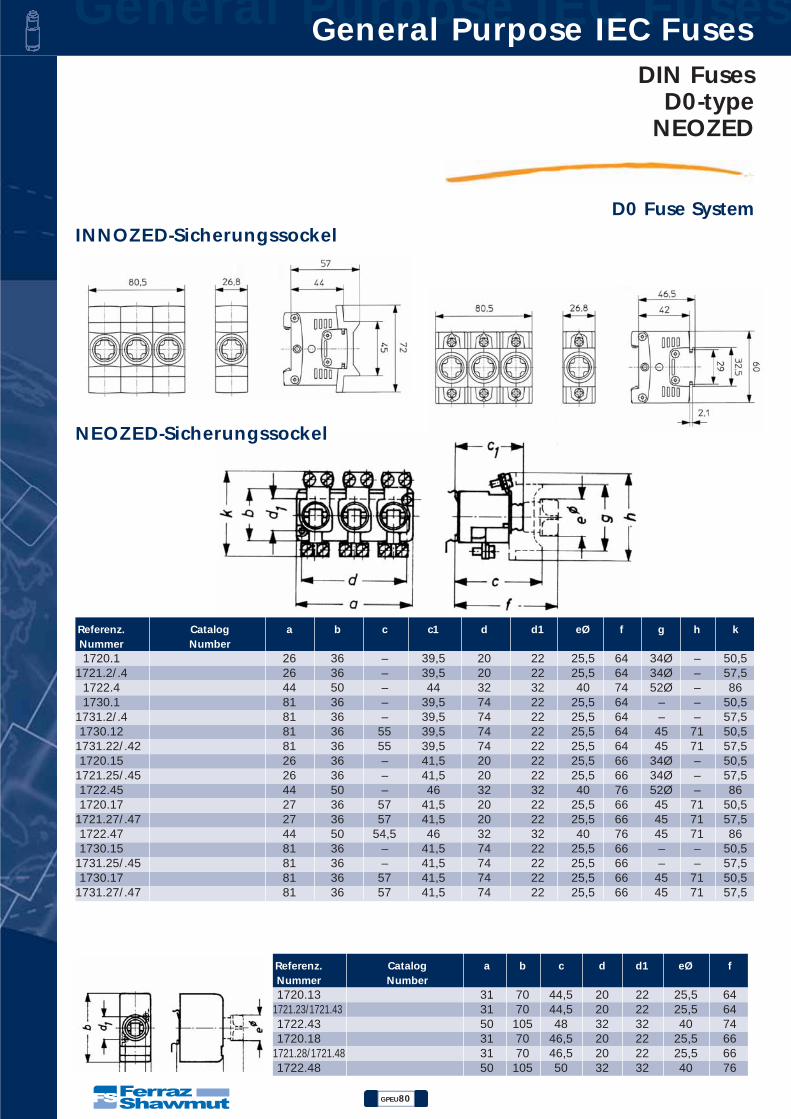
General Purpose IEC Fuses General Purpose IEC Fuses
GPEU80
DIN FusesD0-type
NEOZED
D0 Fuse SystemINNOZED-Sicherungssockel
Referenz. Catalog a b c c1 d d1 eØ f g h kNummer Number1720.1 26 36 – 39,5 20 22 25,5 64 34Ø – 50,5
1721.2/.4 26 36 – 39,5 20 22 25,5 64 34Ø – 57,5 1722.4 44 50 – 44 32 32 40 74 52Ø – 86 1730.1 81 36 – 39,5 74 22 25,5 64 – – 50,5
1731.2/.4 81 36 – 39,5 74 22 25,5 64 – – 57,5 1730.12 81 36 55 39,5 74 22 25,5 64 45 71 50,5
1731.22/.42 81 36 55 39,5 74 22 25,5 64 45 71 57,5 1720.15 26 36 – 41,5 20 22 25,5 66 34Ø – 50,5
1721.25/.45 26 36 – 41,5 20 22 25,5 66 34Ø – 57,5 1722.45 44 50 – 46 32 32 40 76 52Ø – 86 1720.17 27 36 57 41,5 20 22 25,5 66 45 71 50,5
1721.27/.47 27 36 57 41,5 20 22 25,5 66 45 71 57,5 1722.47 44 50 54,5 46 32 32 40 76 45 71 86 1730.15 81 36 – 41,5 74 22 25,5 66 – – 50,5
1731.25/.45 81 36 – 41,5 74 22 25,5 66 – – 57,5 1730.17 81 36 57 41,5 74 22 25,5 66 45 71 50,5
1731.27/.47 81 36 57 41,5 74 22 25,5 66 45 71 57,5
Referenz. Catalog a b c d d1 eØ fNummer Number1720.13 31 70 44,5 20 22 25,5 64
1721.23/1721.43 31 70 44,5 20 22 25,5 64 1722.43 50 105 48 32 32 40 74 1720.18 31 70 46,5 20 22 25,5 66
1721.28/1721.48 31 70 46,5 20 22 25,5 66 1722.48 50 105 50 32 32 40 76
NEOZED-Sicherungssockel

DIN FusesD0-typeNEOZED
GPEU81
General Purpose IEC Fuses General Purpose IEC Fuses
D0 Fuse SystemNEOZEDSchraubkappen
NEOZEDSicherungseinsätze
NEOZEDHülsenpasseinsätze
NEOZEDAbdeckungen
LINOZED-Sicherungssockel
Referenz. Catalog a bNummer Number
1714. 29,5 23 1715. 29,5 23 1710. 31 25 1711. 31 25 1712. 37 40
Referenz. Catalog a b cNummer Number1718.008 60 26,8 23
1728.7 71 26,8 23 1728. 60 44 18
1732.7 71 81 23
Referenz. Catalog a bNummer Number
D01 36 11 D02 36 15 D03 43 22
Referenz. Catalog a bNummer Number
1705. 10 12 1706. 10 16 1707. 10 27
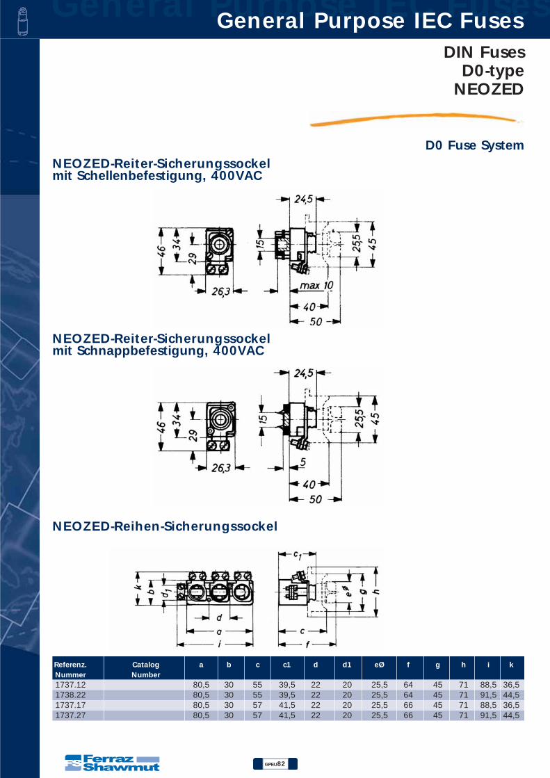
General Purpose IEC Fuses General Purpose IEC Fuses
GPEU82
DIN FusesD0-type
NEOZED
D0 Fuse SystemNEOZED-Reiter-Sicherungssockelmit Schellenbefestigung, 400VAC
NEOZED-Reiter-Sicherungssockelmit Schnappbefestigung, 400VAC
NEOZED-Reihen-Sicherungssockel
Referenz. Catalog a b c c1 d d1 eØ f g h i kNummer Number1737.12 80,5 30 55 39,5 22 20 25,5 64 45 71 88,5 36,5 1738.22 80,5 30 55 39,5 22 20 25,5 64 45 71 91,5 44,5 1737.17 80,5 30 57 41,5 22 20 25,5 66 45 71 88,5 36,5 1737.27 80,5 30 57 41,5 22 20 25,5 66 45 71 91,5 44,5

General Purpose IEC Fuses General Purpose IEC Fuses
GPEU84
DIN FusesD-type
DIAZED
D Fuse System
2 – 200 A, 500 V, 690 V
Line protection fuses gL-gGIEC 60269 parts1, 3 and 3-1DIN VDE 0636 Parts 10, 30 and 31
Dimensions are stipulated in the following regulations:DIN 49360 D Fuse-linksDIN 49515 D Fuse-linksDIN 49367 D Fuse-links, long designDIN 49514 D Screw capsDIN 49510 D Fuse basesDIN 49362 D Gauge ringsDIN 49516 D Screw gauge pieces
Structure of the D fuse systemLike the modern NEOZED system, the D-Fuse system consists of fuse base, gauge piece, fuse link andscrew cap. It is designed for a rated voltage of 500V. Noninterchangeability of rated current is guaran-teed from one current level to the other above 6 Amps. This is ensured by graduating the diameter ofthe bottom contact of the fuse-link along with corresponding fixed diameters for the gauge piece.

DIN FusesD-typeDIAZED
GPEU85
General Purpose IEC Fuses General Purpose IEC Fuses
D Fuse SystemD Fuse basesfor snap-on fastening 500 VAC / 690 VAC
D Fuse basesfor screw fixing 500 VAC / 690 VAC
Rated in Max. cross Previous Reference CatalogSize Current (A) Pole sect. mm2 Reference Number Pack Number
without shock-proof protection cover DII 25 1* 6 00685.100000 K207055 15 DIII 63 4* 16 00686.400000 V215597 15
with shock-proof protection cover DII 25 1 6 00685.110000 D211511 10 DIII 63 4 16 00686.410000 C216110 10
* Terminal type see following pages
Rated in Max. cross Previous Reference CatalogSize Current (A) Pole sect. mm2 Reference Number Pack Number
without shock-proof protection cover DII 25 1* 6 00081.100000 K218670 15 DIII 63 4* 16 00072.400000 H212021 15
with shock-proof protection cover DII 25 1* 6 00081.110000 Z219189 10 DIII 63 4* 16 00072.410000 A212543 10
* Terminal type see following pages
D Fuse-links2 - 200A fast acting (CEE-16 standard), 500 VAC
Rated in Gauge Previous Reference CatalogSize Current (A) Color Reference Number Pack NumberNDZ 2 pink 00594.002000 C222918 25 NDZ 4 brown 00594.004000 L200708 25 NDZ 6 green 00594.006000 A201250 25 NDZ 10 red 00594.010000 L201766 25 NDZ 16 gray 00594.016000 D207049 25 NDZ 20 blue 00594.020000 B211509 25 NDZ 25 yellow 00594.025000 Y212541 25 DII 2 pink 00597.002000 E213559 25 DII 4 brown 00597.004000 D214064 25 DII 6 green 00597.006000 L214577 25 DII 10/6 (1) red 00597.610000 X218152 25 DII 10 red 00597.010000 S215089 25 DII 16 gray 00597.016000 A216108 25 DII 20 blue 00597.020000 J217128 25 DII 25 yellow 00597.025000 P217639 25 DIII 35 Black 00598.035000 J218669 25 DIII 50 white 00598.050000 J222165 25 DIII 63 copper 00598.063000 M200709 25
(1) with base contact stud for 6 A
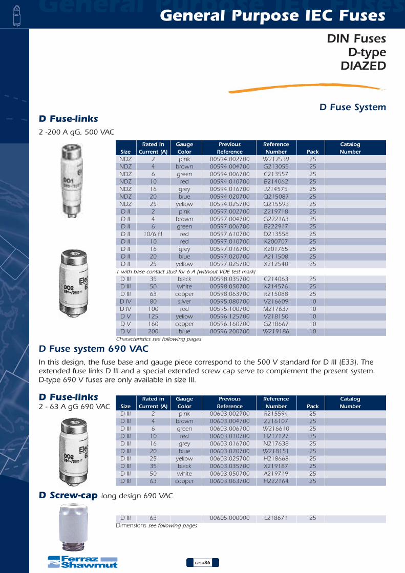
General Purpose IEC Fuses General Purpose IEC Fuses
GPEU86
DIN FusesD-type
DIAZED
D Fuse SystemD Fuse-links2 -200 A gG, 500 VAC
D Fuse system 690 VACIn this design, the fuse base and gauge piece correspond to the 500 V standard for D III (E33). Theextended fuse links D III and a special extended screw cap serve to complement the present system. D-type 690 V fuses are only available in size III.
Rated in Gauge Previous Reference CatalogSize Current (A) Color Reference Number Pack NumberD III 2 pink 00603.002700 R215594 25 D III 4 brown 00603.004700 Z216107 25 D III 6 green 00603.006700 W216610 25 D III 10 red 00603.010700 H217127 25 D III 16 grey 00603.016700 N217638 25 D III 20 blue 00603.020700 W218151 25 D III 25 yellow 00603.025700 H218668 25 D III 35 black 00603.035700 X219187 25 D III 50 white 00603.050700 A219719 25 D III 63 copper 00603.063700 H222164 25
D III 63 00605.000000 L218671 25 Dimensions see following pages
Rated in Gauge Previous Reference CatalogSize Current (A) Color Reference Number Pack NumberNDZ 2 pink 00594.002700 W212539 25 NDZ 4 brown 00594.004700 G213055 25 NDZ 6 green 00594.006700 C213557 25 NDZ 10 red 00594.010700 B214062 25 NDZ 16 grey 00594.016700 J214575 25 NDZ 20 blue 00594.020700 Q215087 25 NDZ 25 yellow 00594.025700 Q215593 25 D II 2 pink 00597.002700 Z219718 25 D II 4 brown 00597.004700 G222163 25 D II 6 green 00597.006700 B222917 25 D II 10/6 f1 red 00597.610700 D213558 25 D II 10 red 00597.010700 K200707 25 D II 16 grey 00597.016700 K201765 25 D II 20 blue 00597.020700 A211508 25 D II 25 yellow 00597.025700 X212540 25
1 with base contact stud for 6 A (without VDE test mark) D III 35 black 00598.035700 C214063 25 D III 50 white 00598.050700 K214576 25 D III 63 copper 00598.063700 R215088 25 D IV 80 silver 00595.080700 V216609 10 D IV 100 red 00595.100700 M217637 10 D V 125 yellow 00596.125700 V218150 10 D V 160 copper 00596.160700 G218667 10 D V 200 blue 00596.200700 W219186 10
Characteristics see following pages
D Fuse-links2 - 63 A gG 690 VAC
D Screw-cap long design 690 VAC

DIN FusesD-typeDIAZED
GPEU87
General Purpose IEC Fuses General Purpose IEC Fuses
D Fuse SystemD Screw capsPorcelain and Plastic, 500 VAC
Rated in Gauge Previous Reference CatalogSize Current (A) Color Reference Number Pack Number
Porcelain with testing hole DII 25 E 27 00690.000200 E218619 20 DIII 63 E 33 00691.000200 B213004 20
Porcelain without testing hole NDZ 25 E 16 00589.000000 Z216613 50 DII 25 E 27 00690.000000 Z218108 20 DIII 63 E 33 00691.000000 F211973 20 DIV 100 R11/4 00592.000000 Y216060 10
Plastic with testing hole DII 25 E 27 02071.000000 L201720 20 DII 63 E 33 02072.000000 E214019 20
D Gauge pieceRated in Gauge Previous Reference Catalog
Size Current (A) Color Reference Number Pack NumberNDZ 2 pink 01655.002000 B212544 50 NDZ 4 brown 01655.004000 M213060 50 NDZ 6 green 01655.006000 H213562 50 NDZ 10 red 01655.010000 G214067 50 NDZ 16 grey 01655.016000 P214580 50
D Screw gauge pieces for DII / DIII
D II 2 pink 01657.002000 A219190 25 D II 4 brown 01657.004000 D219722 25 D II 6 green 01657.006000 L222167 25 D II 10 red 01657.010000 F222921 25 D II 16 grey 01657.016000 P200711 25 D II 20 blue 01657.020000 D201253 25 D II 25 yellow 01657.025000 P201769 25 D III 35 black 01658.035000 C207071 25 D III 50 white 01658.050000 E211512 25 D III 63 copper 01658.063000 J212022 25
D Gauge rings for DII / DIII, TRI60 System
D II 2 pink 01652.002000 W215092 50 D II 4 brown 01652.004000 W215598 50 D II 6 green 01652.006000 D216111 50 D II 10 red 01652.010000 A216614 50 D II 16 grey 01652.016000 M217131 50 D II 20 blue 01652.020000 S217642 50 D II 25 yellow 01652.025000 A218155 50 D III 2 pink 01653.002000 M218672 50 D III 4 brown 01653.004000 E219723 50 D III 6 green 01653.006000 M222168 50 D III 10 red 01653.010000 G222922 50 D III 16 grey 01653.016000 Q200712 50 D III 20 blue 01653.020000 E201254 50 D III 25 yellow 01653.025000 Q201770 50 D III 35 black 01653.035000 L207079 50 D III 50 white 01653.050000 F211513 50
Dimensions see following pages

General Purpose IEC Fuses General Purpose IEC Fuses
GPEU88
DIN FusesD-type
DIAZED
D Fuse SystemKey for D gauge pieces
D Cover insulating material
Previous Reference CatalogSize
Reference NumberPack
Number
DII, DIII 01657.993000 E216112 10
Single poleD II (40 mm width) 00685.700000* H214068 30D III (50 mm width) 00686.700000* X215093 30D II (45 mm width) 00685.709000 Q214581 30D III (54 mm width) 00686.709000 X215599 30* Standart version
Tiple pole
D II 00625.700000 N213061 8D II 00626.700000 J213563 8
D Touch Protection ringsPlastic
D II 00181.900000 K222120 50D III 00182.900000 A222870 50
Porcelain
D II 00081.900000 C219675 30D III 00072.900000 K212023 20
D Adapter fittings
D Locking caps
Locking keys
for DII-fuses links in D III-bases
D II/ D III 00581.000000 C212545 50
Supply boards 01714.820000* K213564* 10Industry 01714.830000 J214069 10
*For authorized energy supplier personnel only
DII Supply boards1) 02071.800000* B216615* 10DII Industry2) 02071.810000 N217132 10
DIII Supply boards1) 02072.800000* T217643* 10DIII Industry2) 02072.810000 B218156 10
* For authorized energy supplier personnel only1) black top, red screw pitch2) red top, black screw pitch

DIN FusesD-typeDIAZED
GPEU89
General Purpose IEC Fuses General Purpose IEC Fuses
D Fuse System
Time-current characteristics of D Fuses 2…100 A gL-gG
RATED CURRENT In IN A
PROSPECTIVE CURRENT Ip IN A
VIR
TUA
L PRE-A
RC
ING
TIM
E
T IN
S
FOR
WA
RD
CU
RREN
T
ID I
N K
A
SHORT CIRCUIT CURRENT IP
IN KA
RA
TED
CU
RREN
T I
N I
N A
Forward current characteristics of DIAZED fuses 2…100 A gL-gG
103
102
101
100
10-1
10-2
10-3
2 Ip 2 Ip 2 20
10
4
2
1
0,4
0,2
0,1
2 4 101 2 4 102 2 4 103 2 4 104 0,1 0,2 0,4 1 2 4 10 20 100
10080
6550
35 25
20
16
106
4
2
D Fuse-links D Screw caps D Covers D touch protection rings
Dimensions
Terminal types1 2 4 6
Clamp terminal Twin Screw terminal Twin Screw terminalTwin Screw terminal
Clamp terminal
0
Screw terminal Twin Screw terminal Clamp terminalScrew terminal
Cat a1
bXNumber
NDZ 50 12DII 50 22DIII 50 27DIV 63 37DV 65 45
Cat a bNumber
690.0002 42 34691.0002 43 42589.0002 34 27
690 42 34691 43 42592 52 60
2071 42 332072 43 40
Cat a b CNumber
685.7 40 90 22686.7 50 90 22
685.709 45 90 22686.709 54 90 22
625.7 107 107 51626.7 127 130 51
Cat a b CNumber
181.9 17,5 44,5 40,5182.9 19 54 50,581.9 18,5 43,5 39,872.9 18 53,5 50,5
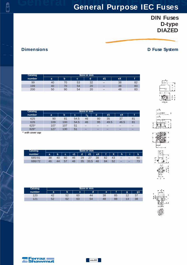
General Purpose IEC Fuses General Purpose IEC Fuses
GPEU90
DIN FusesD-type
DIAZED
D Fuse SystemDimensions
99 40 70 53 32 – 38 82199 40 70 54 20 – 38 83200 50 90 54 20 – 48 83
Catalog Sizes in mmnumber a b c d d1 eX f
685/81 38 40 60 46 29 27 38 82 43 – – 60686/72 46 44 57 48 35 33,5 48 84 52 – – 73
Catalog Sizes in mmnumber a b c c1 d d1 eX f X h i k
120 42 52 60 44 38 85 12 37121 52 62 63 54 48 88 13 38
Catalog Sizes in mmnumber a b c d e f g g1
625 90 81 54.5 46 80 35 37 81626 109 100 54.5 46 95 49.5 46.5 81625* 107 107 51 – – – – –626* 127 130 51 – – – – –
* with cover cap
Catalog Sizes in mmnumber a b c c1 d d1 eX f
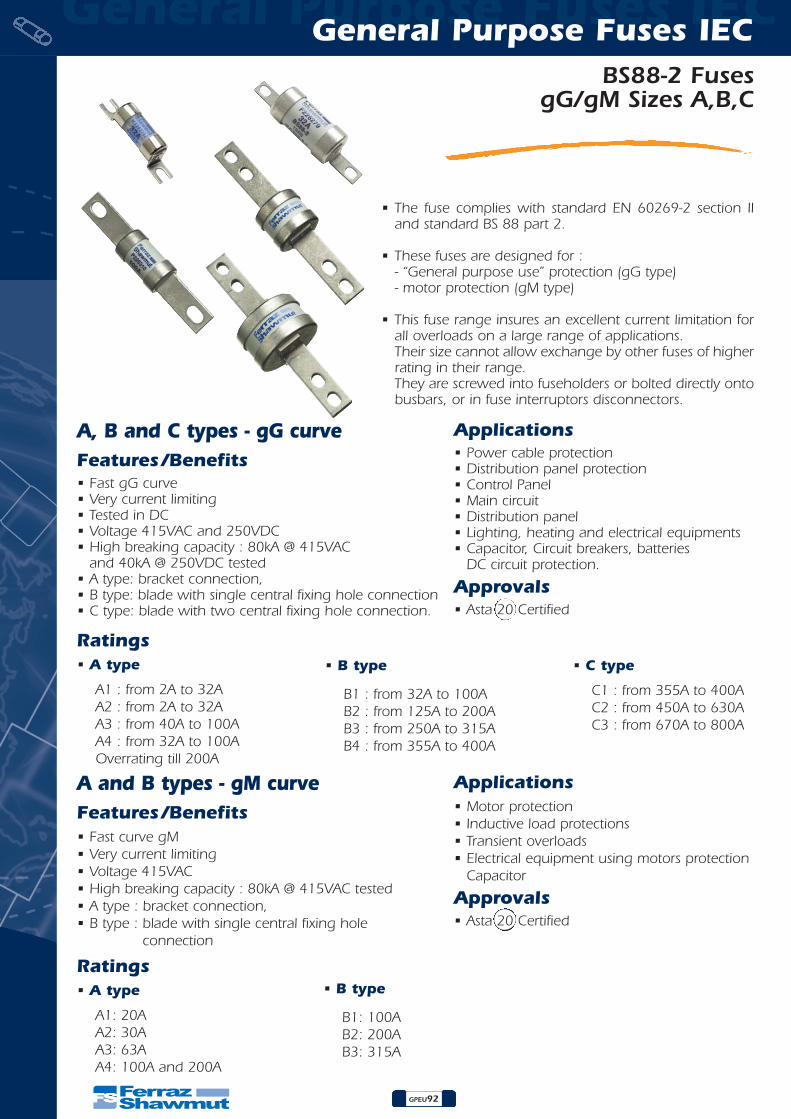
GPEU92
BS88-2 FusesgG/gM Sizes A,B,C
General Purpose Fuses IECGeneral Purpose Fuses IEC
• The fuse complies with standard EN 60269-2 section IIand standard BS 88 part 2.
• These fuses are designed for :- “General purpose use” protection (gG type)- motor protection (gM type)
• This fuse range insures an excellent current limitation forall overloads on a large range of applications.Their size cannot allow exchange by other fuses of higherrating in their range.They are screwed into fuseholders or bolted directly ontobusbars, or in fuse interruptors disconnectors.
A, B and C types - gG curveFeatures/Benefits• Fast gG curve• Very current limiting• Tested in DC• Voltage 415VAC and 250VDC• High breaking capacity : 80kA @ 415VAC
and 40kA @ 250VDC tested• A type: bracket connection,• B type: blade with single central fixing hole connection• C type: blade with two central fixing hole connection.
Applications• Power cable protection• Distribution panel protection• Control Panel • Main circuit• Distribution panel• Lighting, heating and electrical equipments• Capacitor, Circuit breakers, batteries
DC circuit protection.
Approvals• Asta 20 Certified
A and B types - gM curveFeatures/Benefits• Fast curve gM• Very current limiting• Voltage 415VAC • High breaking capacity : 80kA @ 415VAC tested• A type : bracket connection,• B type : blade with single central fixing hole
connection
Applications• Motor protection• Inductive load protections• Transient overloads• Electrical equipment using motors protection
Capacitor
Approvals• Asta 20 Certified
Ratings• A type
A1 : from 2A to 32AA2 : from 2A to 32AA3 : from 40A to 100AA4 : from 32A to 100AOverrating till 200A
• B type
B1 : from 32A to 100AB2 : from 125A to 200AB3 : from 250A to 315AB4 : from 355A to 400A
Ratings• A type
A1: 20AA2: 30AA3: 63AA4: 100A and 200A
• B type
B1: 100AB2: 200AB3: 315A
• C type
C1 : from 355A to 400AC2 : from 450A to 630AC3 : from 670A to 800A
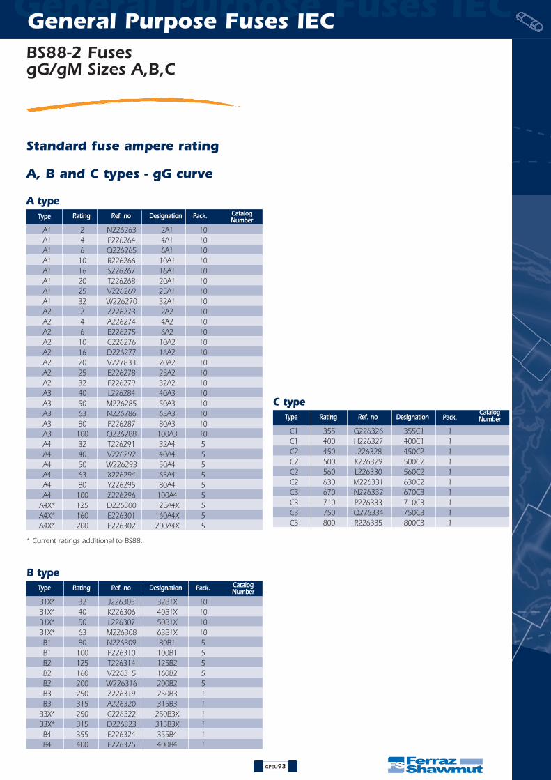
GPEU93
General Purpose Fuses IECGeneral Purpose Fuses IEC
Standard fuse ampere rating
A, B and C types - gG curve
A type
A1 2 N226263 2A1 10A1 4 P226264 4A1 10A1 6 Q226265 6A1 10A1 10 R226266 10A1 10A1 16 S226267 16A1 10A1 20 T226268 20A1 10A1 25 V226269 25A1 10A1 32 W226270 32A1 10A2 2 Z226273 2A2 10A2 4 A226274 4A2 10A2 6 B226275 6A2 10A2 10 C226276 10A2 10A2 16 D226277 16A2 10A2 20 V227833 20A2 10A2 25 E226278 25A2 10A2 32 F226279 32A2 10A3 40 L226284 40A3 10A3 50 M226285 50A3 10A3 63 N226286 63A3 10A3 80 P226287 80A3 10A3 100 Q226288 100A3 10A4 32 T226291 32A4 5A4 40 V226292 40A4 5A4 50 W226293 50A4 5A4 63 X226294 63A4 5A4 80 Y226295 80A4 5A4 100 Z226296 100A4 5
A4X* 125 D226300 125A4X 5A4X* 160 E226301 160A4X 5A4X* 200 F226302 200A4X 5
Type Rating Ref. no Designation Pack. CatalogNumber
B type
B1X* 32 J226305 32B1X 10B1X* 40 K226306 40B1X 10B1X* 50 L226307 50B1X 10B1X* 63 M226308 63B1X 10B1 80 N226309 80B1 5B1 100 P226310 100B1 5B2 125 T226314 125B2 5B2 160 V226315 160B2 5B2 200 W226316 200B2 5B3 250 Z226319 250B3 1B3 315 A226320 315B3 1
B3X* 250 C226322 250B3X 1B3X* 315 D226323 315B3X 1B4 355 E226324 355B4 1B4 400 F226325 400B4 1
Type Rating Ref. no Designation
C type
C1 355 G226326 355C1 1C1 400 H226327 400C1 1C2 450 J226328 450C2 1C2 500 K226329 500C2 1C2 560 L226330 560C2 1C2 630 M226331 630C2 1C3 670 N226332 670C3 1C3 710 P226333 710C3 1C3 750 Q226334 750C3 1C3 800 R226335 800C3 1
Type Rating Ref. no Designation
* Current ratings additional to BS88.
Pack. CatalogNumber
Pack.CatalogNumber
BS88-2 FusesgG/gM Sizes A,B,C

General Purpose Fuses IECGeneral Purpose Fuses IEC
GPEU94
BS88-2 FusesgG/gM Sizes A,B,C
DimensionsA type
A1 2, 4, 6, 10, 16, 20, 25*, 32*, 20M25, 20M32mm 33 12,7 56 9,5 0,8 44,25 4,8 14,3
In 1-1/4 1/2 2-3/16 3/8 1/32 1-3/4 3/16 9/16
A2 2, 4, 6, 10, 16, 20, 25, 32, 32M40, 32M50, 32M63mm 49 22 86 9 1,2 73 5,5 8 24
In 1-15/16 7/8 3-3/8 11/32 3/64 2-7/8 7/32 5/16 15/16
A3 40, 50, 63mm 49 22 89 13 1,2 73 5,5 24
In 1-15/16 7/8 3-1/2 1/2 3/64 2-7/8 7/32 15/16
A3 80*, 100*, 63M80, 63M100mm 49 26 89 13 1,2 73 5,5 28
In 1-15/16 1-1/32 3-1/2 1/2 3/64 2-7/8 7/32 1-3/32
A4 32, 40, 50, 63mm 51 22 110 20 2,4 94 8,7 11 25,4
In 2 7/8 4-5/16 3/4 3/32 3-11/16 11/32 7/16 1
A4 80, 100mm 51 26 110 20 2,4 94 8,7 11 29
In 2 1-1/32 4-5/16 3/4 3/32 3-11/16 11/32 7/16 1-1/8
A4X 125, 160, 200, 100M125, 100M160, 100M200mm 51 35 110 20 2,4 94 8,7 11 38
In 2 1-3/8 4-5/16 3/4 3/32 3-11/16 11/32 7/16 1-1/2
A4X 200M250*, 200M315*mm 51 41 110 20 2,4 94 8,7 11 45
In 2 1-5/8 4-5/16 3/4 3/32 3-11/16 11/32 7/16 1-3/4
Ref. BS 88 Current ratings (A)
Dimensions (mm & In)A max B max D max E max F nom G nom H nom J nom K max
openhole
openhole
openhole
* Current ratings additional to BS88.
A and B types - gM curve
A type
A1 20M25 X226271 20M25A1 10A1 20M32 Y226272 20M32A1 10A2 32M40 G226280 32M40A2 10A2 32M50 H226281 32M50A2 10A2 32M63 K226283 32M63A2 10A3 63M80 R226289 63M80A3 10A3 63M100 S226290 63M100A3 10A4 100M125 A226297 100M125A4 5A4 100M160 B226298 100M160A4 5A4 100M200 C226299 100M200A4 5A4X 200M250 G226303 200M250A4X 1A4X 200M315 H226304 200M315A4X 1
Type Rating Ref. no Designation Pack. CatalogNumber
B type
B1 100M125 Q226311 100M125B1 5B1 100M160 R226312 100M160B1 5B1 100M200 S226313 100M200B1 5B2 200M250 X226317 200M250B2 1B2 200M315 Y226318 200M315B2 1B3 315M400 B226321 315M400B3 1
Type Rating Ref. no Designation Pack. CatalogNumber
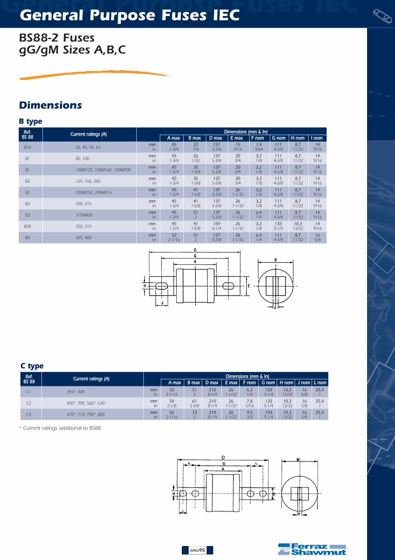
General Purpose Fuses IECGeneral Purpose Fuses IEC
GPEU95
Dimensions
C type
C1 355*, 400 mm 52 51 210 26 6,3 133 10,3 16 25,4In 2-1/16 2 8-1/4 1-1/32 1/4 5-1/4 13/32 5/8 1
C2 450*, 500, 560*, 630 mm 54 61 210 26 7,8 133 10,3 16 25,4In 2-1/8 2-3/8 8-1/4 1-1/32 5/16 5-1/4 13/32 5/8 1
C3 670*, 710, 750*, 800 mm 56 73 210 26 9,5 133 10,3 16 25,4In 2-1/16 2 8-1/4 1-1/32 3/8 5-1/4 13/32 5/8 1
Ref. BS 88 Current ratings (A) Dimensions (mm & In)
A max B max D max E max F nom G nom H nom J nom L nom
* Current ratings additional to BS88.
BS88-2 FusesgG/gM Sizes A,B,C
B type
B1X 32, 40, 50, 63mm 45 22 137 15 1,4 111 8,7 14
in 1-3/4 7/8 5-3/8 9/16 3/64 4-3/8 11/32 9/16
B1 80, 100mm 45 26 137 20 3,2 111 8,7 14
in 1-3/4 1/32 5-3/8 3/4 1/8 4-3/8 11/32 9/16
B1 100M125, 100M160, 100M200mm 45 35 137 20 3,2 111 8,7 14
in 1-3/4 1-3/8 5-3/8 3/4 1/8 4-3/8 11/32 9/16
B2 125, 160, 200mm 45 35 137 20 3,2 111 8,7 14
in 1-3/4 1-3/8 5-3/8 3/4 1/8 4-3/8 11/32 9/16
B2 200M250, 200M315mm 45 41 137 26 3,2 111 8,7 14
in 1-3/4 1-5/8 5-3/8 1-1/32 1/8 4-3/8 11/32 9/16
B3 250, 315mm 45 41 137 26 3,2 111 8,7 14
in 1-3/4 1-5/8 5-3/8 1-1/32 1/8 4-3/8 11/32 9/16
B3 315M400mm 45 51 137 26 6,4 111 8,7 14
in 1-3/4 2 5-3/8 1-1/32 1/4 4-3/8 11/32 9/16
B3X 250, 315mm 45 41 159 26 3,2 133 10,3 14
in 1-3/4 1-5/8 6-1/4 1-1/32 1/8 5-1/4 13/32 9/16
B4 355, 400mm 52 51 137 26 6,4 111 8,7 16
in 2-1/16 2 5-3/8 1-1/32 1/4 4-3/8 11/32 5/8
Ref. BS 88 Current ratings (A) Dimensions (mm & In)
A max B max D max E max F nom G nom H nom I nom

General Purpose Fuses IECGeneral Purpose Fuses IEC
GPEU96
BS88-2 FusesgG/gM Sizes A,B,C
gG and gM fuse-link selection
0,75 1 2 6 - 4 -1,1 1,5 2,5 10 - 6 -1,5 2 3,5 10 - 6 -2,2 3 5 16 - 10 -3 4 6,5 20 - 16 -4 5 8 25 20M25 16 -
5,5 7,5 11 32 20M32 20 -7,5 10 14 40 32M40 25 20M2510 13,5 19 50 32M50 32 20M3211 15 21 50 32M50 32 -15 20 28 63 32M63 40 32M40
18,5 25 35 80 63M80 50 -22 30 41 100 63M100 50 -26 35 48 100 63M100 63 -30 40 55 125 100M125 80 63M8033 45 62 160 100M160 80 63M8037 50 69 160 100M160 100 -45 60 83 200 100M200 100 -53 70 97 200 100M200 125 100M12555 75 100 200 100M200 125 100M12560 80 110 250 200M250 160 -67 90 120 250 200M250 160 -75 100 135 250 200M250 160 -90 120 160 315 200M315 200 -93 125 170 355* 315M400* 200 -110 150 200 400 315M400* 250 200M250130 175 230 400 315M400* 315 -150 200 260 450* 400M500* 315 -160 215 280 500 400M500* 355* 315M400*170 225 290 500 400M500* 355* 315M400*180 250 320 560* - 400 -200 270 350 630 - 400 -220 300 380 670* - 450 400M500*250 335 420 710* - 500 -260 350 450 750* - 560* -300 400 500 800 - 630 -
Motor ratingHP
kW IngG gM gG gM
Direct-on-line start (7 x FLC for 10 sec)Fuse-link rating (amperes)
Assisted start (3,5 x FLC for 20 sec)Fuse-link rating (amperes)
Fuse-link selection for 3 phase 415 V AC induction motor circuit
2 - 0,64 - 1,36 - 2,310 - 4,116 - 6,020 - 7,925 20M25 1032 20M32 1340 32M40 1850 32M50 2663 32M63 3080 63M80 40100 63M100 54125 100M125 61160 100M160 82200 - 110250 200M250 150315 200M315 170355* 315M400* 200400 315M400* 240450* 400M500* 280500 400M500* 310560* - 350630 - 380670* - 420710* - 450750* - 480800 - 510
gG gM In
Direct-on-line start (7 x FLC for 10 sec)Fuse-link
rating (amperes)Maximum
motor
2 - 1,34 - 2,46 - 4,310 - 6,416 - 1120 - 1425 20M25 1932 - 2440 32M40 3150 - 4663 - 5180 - 69100 - 94125 - 110160 - 150200 - 180250 - 220315 - 250355* - 310400 - 340450* 400M500* 380500 - 430560* - 460630 - 500670* - 530710* - 550750* - 570800 - 600
gG gM In
Assisted start (3,5 x FLC for 20 sec)Fuse-link
rating (amperes)Maximum
motor
Maximum full load current starting capability
This data is based upon normal startingconditions and usual efficiency andpower factor.Conditions such as long run-up times,large numbers of start in succession,high ambient temperature or abnormaltransients during start/delta switchingmay necessitate adjustments to fuse-linkselection.
* Current ratings additional to BS88.
* Current ratings additional to BS88.

General Purpose Fuses IECGeneral Purpose Fuses IEC
GPEU97
BS88-2 FusesgG/gM Sizes A,B,C
gG
gM
Curves from BS88 standard part 1 and 2 (sections 2.1 and 2.2) of 1988.Voltage rating : 415 V. Interrupting rating : 80 kA under 415 V.* Current ratings additional to BS88.
Fuse
-link
ratin
g (A
)
PRE-A
RC
ING
TIM
E (
S)PRE-A
RC
ING
TIM
E (
S)
PROSPECTIVE CURRENT (R.M.S. SYMMETRICAL A)
PROSPECTIVE CURRENT (R.M.S. SYMMETRICAL A)
Fuse
-link
ratin
g (A
)
Time/current data20000
4 hours10000
1000
100
10
1
0.1
0.0051 10 100 1000 10000 100000
200004 hours10000
1000
100
10
1
0.1
0.0051 10 100 1000 10000 100000

General Purpose Fuses IECGeneral Purpose Fuses IEC
GPEU98
BS88-2 FusesgG/gM Sizes A,B,C
I2t characteristics
Dissipated power* Current ratings additional to BS88
* Current ratings additional to BS88
Operating I2t at 415 V.Pre-arcing I2t
BS 88 part 2 (Section 2.2) standardized limit
107
106
105
104
103
102
10
0

General Purpose Fuses IECGeneral Purpose Fuses IEC
GPEU99
BS88-2 FusesgG/gM Sizes A,B,C
Nominal current derating by temperature- When the fuse-link is mounted in the open, the elevated
temperature is the ambient air temperature (Ta).- When the fuse-link is mounted in an enclosure, the elevated
temperature is the internal “fluid environment temperature”(Te) within the enclosure.
- When it is not known, it should be assumed to be 15°C higherthan the ambient air temperature external to the enclosure, i.e.Te = Ta + 15°C.
Examples:- 100A fuse-link mounted in the open at an ambient air
temperature of 65°C. Current carrying capability = 100A.
- 200A fuse-link mounted in the open at an ambient airtemperature of 60°C. Current carrying capability = 195A.
- 400A fuse-link mounted in an enclosure having an internaltemperature of 65°C. Current carrying capability = 370A.
- 800A fuse-link mounted in an enclosure with an unknowninternal temperature and an external ambient air temperatureof 40°C. Assume the internal temperature is 55°C (40°C +15°C). Current carrying temperature = 740A.
Curves and derating comply with BS88 standard part 1 and 2 sections 2.1 and 2.2 of 1988.* Derating also applies, to additional current ratings.
2, 4, 6, 1016 1520 18 1625 23 21 1932 31 30 2940 39 38 3750 49 48 4763 61 59 5780 79 78 76100 98 96 94125 122 119 116160 155 150 145 140200 195 190 185 180 175250 240 230 220 210 200315 310 300 290 270 250355* 345 335 320 300 280400 390 380 370 350 330 310450* 445 430 410 390 370 350500 490 480 460 440 420 400560* 550 530 510 490 470 450630 620 610 590 570 550 530 510 490670* 660 640 620 600 580 560 540 520710* 700 680 660 640 620 600 580 560750* 740 730 710 690 670 650 630 600800 780 760 740 720 700 680 660 640
Fuse-linkrating (A)
Current carrying capability (in amperes) at elevated temperatures
40°C 45°C 50°C 55°C 60°C 65°C 70°C 75°C 80°C
FUSE-LINKSFULLY RATED
Peak let-throughcurrent
* Current ratings additional to BS88
100
100
10
10
1
1
0.1
0.1

General Purpose Fuses IECGeneral Purpose Fuses IEC
GPEU100
BS88-2 FusesgG/gM Sizes F1,F2
•The fuse comply with standard EN 60269-2 section IIand standard BS88 part 2.
•This fuses are designed for :- “general purpose use” protection, (gG type)- motor protection (gM type)
•This fuse range insures an excellent current limitationfor all overloads on a large range of applications.Their size cannot allow exchange by other fuses ofhigher rating in the F type range.They are compact and can be connected with clips.
Fuses designations and ratings
F1 type
F1 2 S226336 2F1 10F1 4 T226337 4F1 10F1 6 V226338 6F1 10F1 10 W226339 10F1 10F1 16 X226340 16F1 10F1 20 Y226341 20F1 10F1 25 Z226342 25F1 10F1 32 A226343 32F1 10F1* 20M25 B226344 20M25F1 10F1* 20M32 C226345 20M32F1 10
Type Rating Ref. no Designation Pack. CatalogNumber
F2 type
F2 10 D226346 10F2 10F2 16 E226347 16F2 10F2 20 F226348 20F2 10F2 25 G226349 25F2 10F2 32 H226350 32F2 10F2 40 J226351 40F2 10F2 50 K226352 50F2 10F2 63 L226353 63F2 10
Type Rating Ref. no Designation
* Selection table for gM fuses : refer to A, B and C types
F1,F2 types - gG curveFeatures/Benefits• Compact design• Curve gG and gM• Very current limiting• Tested in DC• Voltage 415VAC • High breaking capacity : 80kA @ 415VAC • Connection by clips or appropriate fuse holders.
Applications• Power cable protection• Distribution panel protection• Control panel• Main circuit• Lighting, heating and electrical equipments• Capacitor, batteries• Can be used with circuit breakers.
Approvals• Asta 20 Certified
Ratings• F1 type
from 2A to 32A
• F2type
from 10A to 63A
Pack. CatalogNumber

General Purpose Fuses IECGeneral Purpose Fuses IEC
GPEU101
BS88-2 FusesgG/gM Sizes F1,F2
Time/current data
Dimensions
* Current ratings additional to BS88 also comply to the BS 88 standard part 6 of 1988.
F1 415V 2, 4, 6, 10, 16, 20, 25, 32, 20M25*, 20M32* mm 35,5 14,3 62 11,5 0,8 3,5in 1-2/5 9/16 2-7/16 9/20 1/32 1/8
F2 415V 10, 16, 20, 25, 32, 40, 50, 63 mm 39 17,5 69 15 1,4 3,5In 1-7/13 11/16 2-13/8 9/16 1/18 1/8
Current ratings (A)Voltage (Vac) Dimensions (mm)A max B max D max E max F nom N nom
Ref. BS 88
Fuse
-link a
mpere
ratin
g
200004 hours10000
1000
100
10
1
0.1
0.0051 10 100 1000 10000 100000

General Purpose Fuses IECGeneral Purpose Fuses IEC
GPEU102
BS88-2 FusesgG/gM Sizes F1,F2
Curves from BS88 standard part 6of 1988.Voltage rating : 415 VAC. Interrupting rating : 40 kA under 415 VAC.
* Current ratings additional to BS88 alsocomply to the BS 88 standard part 6 of1988.
Curves from BS88 standard part 6 of1988.Voltage rating : 415 VAC. Interrupting rating : 40 kA under 415 VAC.
ASTA 20 certified
* Current ratings additional to BS88 also comply tothe BS 88 standard part 6 of 1988.
I2t characteristics
Dissipated power
Peak let-through current
Curves from BS88 standard part 6 of 1988.Voltage rating : 415 VAC. Interrupting rating : 40 kA under 415 VAC.
* Current ratings additional to BS88 also comply to the BS 88standard part 6 of 1988.
BS 88-part 6 standardized limit
Operating I2t at 415 V.pre-arcing I2t
107
106
105
104
103
102
10
05
4
3
2
1
0
100
100
10
10
1
10.1
0.1