General Packet Radio Service (GPRS); Stage 2 (GSM … · General Packet Radio Service (GPRS);...
42
TS 101 350 V6.2.0 (1999-05) Technical Specification Digital cellular telecommunications system (Phase 2+); General Packet Radio Service (GPRS); Overall description of the GPRS radio interface; Stage 2 (GSM 03.64 version 6.2.0 Release 1997) GLOBAL SYSTEM FOR MOBILE COMMUNICATIONS R
Transcript of General Packet Radio Service (GPRS); Stage 2 (GSM … · General Packet Radio Service (GPRS);...

TS 101 350 V6.2.0 (1999-05)Technical Specification
Digital cellular telecommunications system (Phase 2+);General Packet Radio Service (GPRS);
Overall description of the GPRS radio interface;Stage 2
(GSM 03.64 version 6.2.0 Release 1997)
GLOBAL SYSTEM FOR MOBILE COMMUNICATIONS
R

ETSI
TS 101 350 V6.2.0 (1999-05)2(GSM 03.64 version 6.2.0 Release 1997)
ReferenceRTS/SMG-020364Q6R2 (ci0030o3.PDF)
KeywordsDigital cellular telecommunications system,Global System for Mobile communications
(GSM), General Packet Radio Service (GPRS)
ETSI
Postal addressF-06921 Sophia Antipolis Cedex - FRANCE
Office address650 Route des Lucioles - Sophia Antipolis
Valbonne - FRANCETel.: +33 4 92 94 42 00 Fax: +33 4 93 65 47 16
Siret N° 348 623 562 00017 - NAF 742 CAssociation à but non lucratif enregistrée à laSous-Préfecture de Grasse (06) N° 7803/88
Individual copies of this ETSI deliverablecan be downloaded from
http://www.etsi.orgIf you find errors in the present document, send your
comment to: [email protected]
Copyright Notification
No part may be reproduced except as authorized by written permission.The copyright and the foregoing restriction extend to reproduction in all media.
© European Telecommunications Standards Institute 1999.All rights reserved.

ETSI
TS 101 350 V6.2.0 (1999-05)3(GSM 03.64 version 6.2.0 Release 1997)
Contents
Intellectual Property Rights................................................................................................................................6
Foreword ............................................................................................................................................................6
1 Scope........................................................................................................................................................7
2 References................................................................................................................................................8
3 Abbreviations, symbols and definitions...................................................................................................93.1 Abbreviations..................................................................................................................................................... 93.2 Symbols ............................................................................................................................................................. 93.3 Definitions ......................................................................................................................................................... 9
4 Packet data logical channels ....................................................................................................................94.1 General............................................................................................................................................................. 104.2 Packet Common Control Channel (PCCCH) ................................................................................................... 104.2.1 Packet Random Access Channel (PRACH) - uplink only .......................................................................... 104.2.2 Packet Paging Channel (PPCH) - downlink only ....................................................................................... 104.2.3 Packet Access Grant Channel (PAGCH) - downlink only.......................................................................... 104.2.4 Packet Notification Channel (PNCH) - downlink only .............................................................................. 104.3 Packet Broadcast Control Channel (PBCCH) - downlink only........................................................................ 104.4 Packet Traffic Channels................................................................................................................................... 104.4.1 Packet Data Traffic Channel (PDTCH)...................................................................................................... 104.5 Packet Dedicated Control Channels................................................................................................................. 114.5.1 Packet Associated Control Channel (PACCH)........................................................................................... 114.5.2 Packet Timing advance Control Channel, uplink (PTCCH/U)...................................................................114.5.3 Packet Timing advance Control Channel, downlink (PTCCH/D) .............................................................. 11
5 Mapping of packet data logical channels onto physical channels .........................................................115.1 General............................................................................................................................................................. 115.2 Packet Common Control Channels (PCCCH).................................................................................................. 115.2.1 Packet Random Access Channel (PRACH)................................................................................................ 125.2.2 Packet Paging Channel (PPCH) ................................................................................................................. 125.2.3 Packet Access Grant Channel (PAGCH).................................................................................................... 125.2.4 Packet Notification Channel (PNCH) ........................................................................................................ 125.3 Packet Broadcast Control Channel (PBCCH).................................................................................................. 125.4 Packet Timing advance Control Channel (PTCCH) ........................................................................................ 125.5 Packet Traffic Channels................................................................................................................................... 125.5.1 Packet Data Traffic Channel (PDTCH)...................................................................................................... 125.5.2 Packet Associated Control Channel (PACCH)........................................................................................... 135.6 Downlink resource sharing .............................................................................................................................. 135.7 Uplink resource sharing ................................................................................................................................... 13
6 Radio Interface (Um) .............................................................................................................................136.1 Radio Resource management principles .......................................................................................................... 136.1.1 Allocation of resources for the GPRS ........................................................................................................ 136.1.1.1 Master-Slave concept ........................................................................................................................... 146.1.1.2 Capacity on demand concept ................................................................................................................ 146.1.1.3 Procedures to support capacity on demand........................................................................................... 146.1.1.4 Release of PDCH not carrying PCCCH................................................................................................ 146.1.2 Multiframe structure for PDCH.................................................................................................................. 156.1.3 Scheduling of PBCCH information. ........................................................................................................... 166.1.4 SMS cell broadcast..................................................................................................................................... 166.2 Radio Resource operating modes..................................................................................................................... 166.2.1 Packet idle mode ........................................................................................................................................ 166.2.2 Packet transfer mode .................................................................................................................................. 166.2.3 Correspondence between Radio Resource operating modes and Mobility Management States................. 16
ETSI
TS 101 350 V6.2.0 (1999-05)4(GSM 03.64 version 6.2.0 Release 1997)
6.3 Layered overview of radio interface ................................................................................................................ 176.4 Physical RF Layer............................................................................................................................................ 186.5 Physical Link Layer ......................................................................................................................................... 186.5.1 Layer Services............................................................................................................................................ 186.5.2 Layer Functions.......................................................................................................................................... 186.5.3 Service Primitives ...................................................................................................................................... 186.5.4 Radio Block Structure ................................................................................................................................ 206.5.5 Channel Coding.......................................................................................................................................... 206.5.5.1 Channel coding for PDTCH ................................................................................................................. 206.5.5.2 Channel coding for PACCH, PBCCH, PAGCH, PPCH,PNCH and PTCCH....................................... 226.5.5.3 Channel Coding for the PRACH........................................................................................................... 226.5.5.3.1 Coding of the 8 data bit Packet Access Burst ................................................................................. 226.5.5.3.2 Coding of the 11 data bit Packet Access Burst ............................................................................... 226.5.6 Cell Re-selection ........................................................................................................................................ 226.5.6.1 Measurements for Cell Re-selection ..................................................................................................... 236.5.6.2 Broadcast Information .......................................................................................................................... 236.5.6.3 Optional measurement reports and network controlled cell re-selection .............................................. 236.5.7 Timing Advance......................................................................................................................................... 236.5.7.1 Initial timing advance estimation.......................................................................................................... 246.5.7.2 Continuous timing advance update ....................................................................................................... 246.5.7.2.1 Mapping on the multiframe structure .............................................................................................. 256.5.8 Power control procedure ............................................................................................................................ 266.5.8.1 MS output power .................................................................................................................................. 266.5.8.2 BTS output power................................................................................................................................. 276.5.8.3 Measurements at MS side..................................................................................................................... 276.5.8.3.1 Deriving the C value ....................................................................................................................... 276.5.8.3.2 Derivation of Channel Quality Report ............................................................................................ 276.5.8.4 Measurements at BSS side.................................................................................................................... 286.5.9 Scheduling the MS activities during the PTCCH and idle frames.............................................................. 286.5.10 Discontinuous Reception (DRX)................................................................................................................ 286.6 Medium Access Control and Radio Link Control Layer.................................................................................. 296.6.1 Layer Services............................................................................................................................................ 296.6.2 Layer Functions.......................................................................................................................................... 306.6.3 Service Primitives ...................................................................................................................................... 306.6.4 Model of Operation.................................................................................................................................... 306.6.4.1 Uplink State Flag.................................................................................................................................. 316.6.4.2 Temporary Block Flow......................................................................................................................... 316.6.4.3 Temporary Flow Identity ...................................................................................................................... 326.6.4.4 Medium Access modes ......................................................................................................................... 326.6.4.5 Acknowledged mode for RLC/MAC operation .................................................................................... 326.6.4.6 Unacknowledged mode for RLC/MAC operation ................................................................................ 326.6.4.7 Mobile Originated Packet Transfer ...................................................................................................... 336.6.4.7.1 Uplink Access ................................................................................................................................. 336.6.4.7.2 Dynamic/Extended Dynamic allocation.......................................................................................... 346.6.4.7.2.1 Uplink Packet Transfer.............................................................................................................. 346.6.4.7.2.2 Release of the Resources ........................................................................................................... 356.6.4.7.3 Fixed Allocation.............................................................................................................................. 366.6.4.7.4 Contention Resolution..................................................................................................................... 366.6.4.8 Mobile Terminated Packet Transfer ..................................................................................................... 376.6.4.8.1 Packet Paging.................................................................................................................................. 376.6.4.8.2 Downlink Packet Transfer............................................................................................................... 376.6.4.8.3 Release of the Resources................................................................................................................. 386.6.4.9 Simultaneous Uplink and Downlink Packet Transfer ........................................................................... 386.7 Abnormal cases in GPRS MS Ready State ...................................................................................................... 396.8 PTM-M Data Transfer ..................................................................................................................................... 39

ETSI
TS 101 350 V6.2.0 (1999-05)5(GSM 03.64 version 6.2.0 Release 1997)
Annex A (informative): Bibliography...................................................................................................40
Annex B (informative): Document change history..............................................................................41
History..............................................................................................................................................................42
ETSI
TS 101 350 V6.2.0 (1999-05)6(GSM 03.64 version 6.2.0 Release 1997)
Intellectual Property RightsIPRs essential or potentially essential to the present document may have been declared to ETSI. The informationpertaining to these essential IPRs, if any, is publicly available for ETSI members and non-members, and can be foundin SR 000 314: "Intellectual Property Rights (IPRs); Essential, or potentially Essential, IPRs notified to ETSI in respectof ETSI standards", which is available free of charge from the ETSI Secretariat. Latest updates are available on theETSI Web server (http://www.etsi.org/ipr).
Pursuant to the ETSI IPR Policy, no investigation, including IPR searches, has been carried out by ETSI. No guaranteecan be given as to the existence of other IPRs not referenced in SR 000 314 (or the updates on the ETSI Web server)which are, or may be, or may become, essential to the present document.
ForewordThis Technical Specification (TS) has been produced by the Special Mobile Group (SMG).
The present document defines the overall description for lower-layer functions of the General Packet Radio Service(GPRS) radio interface (Um) within the digital cellular telecommunications system.
The contents of the present document is subject to continuing work within SMG and may change following formal SMGapproval. Should SMG modify the contents of the present document, it will be re-released by SMG with an identifyingchange of release date and an increase in version number as follows:
Version 6.x.y
where:
6 indicates GSM Phase 2+ Release 1997;
x the second digit is incremented for all changes of substance, i.e. technical enhancements, corrections, updates,etc.;
y the third digit is incremented when editorial only changes have been incorporated in the specification.
ETSI
TS 101 350 V6.2.0 (1999-05)7(GSM 03.64 version 6.2.0 Release 1997)
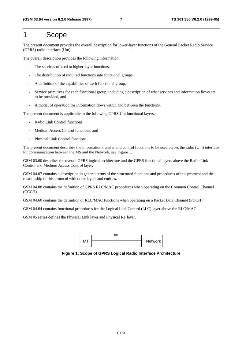
1 ScopeThe present document provides the overall description for lower-layer functions of the General Packet Radio Service(GPRS) radio interface (Um).
The overall description provides the following information:
- The services offered to higher-layer functions,
- The distribution of required functions into functional groups,
- A definition of the capabilities of each functional group,
- Service primitives for each functional group, including a description of what services and information flows areto be provided, and
- A model of operation for information flows within and between the functions.
The present document is applicable to the following GPRS Um functional layers:
- Radio Link Control functions,
- Medium Access Control functions, and
- Physical Link Control functions.
The present document describes the information transfer and control functions to be used across the radio (Um) interfacefor communication between the MS and the Network, see Figure 1.
GSM 03.60 describes the overall GPRS logical architecture and the GPRS functional layers above the Radio LinkControl and Medium Access Control layer.
GSM 04.07 contains a description in general terms of the structured functions and procedures of this protocol and therelationship of this protocol with other layers and entities.
GSM 04.08 contains the definition of GPRS RLC/MAC procedures when operating on the Common Control Channel(CCCH).
GSM 04.60 contains the definition of RLC/MAC functions when operating on a Packet Data Channel (PDCH).
GSM 04.64 contains functional procedures for the Logical Link Control (LLC) layer above the RLC/MAC.
GSM 05 series defines the Physical Link layer and Physical RF layer.
NetworkMT
Um
Figure 1: Scope of GPRS Logical Radio Interface Architecture

ETSI
TS 101 350 V6.2.0 (1999-05)8(GSM 03.64 version 6.2.0 Release 1997)
2 ReferencesThe following documents contain provisions which, through reference in this text, constitute provisions of the presentdocument.
• References are either specific (identified by date of publication, edition number, version number, etc.) ornon-specific.
• For a specific reference, subsequent revisions do not apply.
• For a non-specific reference, the latest version applies.
• A non-specific reference to an ETS shall also be taken to refer to later versions published as an EN with the samenumber.
• For this Release 1997 document, references to GSM documents are for Release 1997 versions (version 6.x.y).
[1] GSM 01.04 (ETR 350): "Digital cellular telecommunications system (Phase 2+); Abbreviationsand acronyms".
[2] GSM 02.60: "Digital cellular telecommunications system (Phase 2+); General Packet RadioService (GPRS); Stage 2 ".
[3] GSM 03.60: "Digital cellular telecommunications system (Phase 2+); Stage 2 Service Descriptionof the General Packet Radio Service (GPRS)".
[4] GSM 04.04: "Digital cellular telecommunications system; Layer 1; General requirements”.
[5] GSM 04.07: "Digital cellular telecommunications system (Phase 2+); Mobile radio interfacesignalling layer 3 General aspects”
[6] GSM 04.08: "Digital cellular telecommunications system (Phase 2+); Mobile radio interface layer3 specification”
[7] GSM 04.60: "Digital cellular telecommunications system(Phase 2+); General Packet Radio Service(GPRS); Mobile Station (MS) – Base Station System (BSS) interface; Radio LinkControl/Medium Access Control (RLC/MAC) protocol".
[8] GSM 04.64: "Digital cellular telecommunications system(Phase 2+); General Packet Radio Service(GPRS); Logical Link Control (LLC)".
[9] GSM 04.65: "Digital cellular telecommunications system (Phase 2+); General Packet RadioService (GPRS); Subnetwork Dependent Convergence Protocol (SNDCP)".
[10] GSM 05.01: "Digital cellular telecommunications system (Phase 2+); Physical layer on the radiopath, General description".
[11] GSM 05.02: "Digital cellular telecommunications system (Phase 2+); Multiplexing and multipleaccess on the radio path".
[12] GSM 05.03: "Digital cellular telecommunications system (Phase 2+); Channel coding".
[13] GSM 05.04: "Digital cellular telecommunications system (Phase 2+); Modulation".
[14] GSM 05.05: "Digital cellular telecommunications system (Phase 2+); Radio transmission andreception".
[15] GSM 05.08: "Digital cellular telecommunications system (Phase 2+); Radio subsystem linkcontrol".
[16] GSM 05.10: "Digital cellular telecommunications system (Phase 2+); Radio subsystemsynchronisation".

ETSI
TS 101 350 V6.2.0 (1999-05)9(GSM 03.64 version 6.2.0 Release 1997)
3 Abbreviations, symbols and definitions
3.1 AbbreviationsIn addition to abbreviations in GSM 01.04 and GSM 02.60 the following abbreviations apply:
BCS Block Check SequenceBEC Backward Error CorrectionBH Block HeaderCS Coding SchemeCU Cell UpdateFH Frame HeaderGGSN Gateway GPRS Support NodeLLC Logical Link ControlMAC Medium Access ControlNCH Notification Channel (for PTM-M on CCCH)NSS Network and Switching SubsystemPACCH Packet Associate Control ChannelPAGCH Packet Access Grant ChannelPBCCH Packet Broadcast Control ChannelPC Power ControlPCCCH Packet Common Control ChannelPDCH Packet Data ChannelPDTCH Packet Data Traffic ChannelPDU Protocol Data UnitPL Physical LinkPNCH Packet Notification Channel (for PTM-M on PCCCH)PPCH Packet Paging ChannelPRACH Packet Random Access ChannelPSI Packet System InformationPTCCH Packet Timing Advance Control ChannelRLC Radio Link ControlSGSN Serving GPRS Support NodeSNDC Subnetwork Dependent ConvergenceTA Timing AdvanceTBF Temporary Block FlowTFI Temporary Frame IdentityUSF Uplink State Flag
3.2 SymbolsFor the purposes of the present document, the following symbols apply:
Gb Interface between an SGSN and a BSC.Um Interface between MS and GPRS fixed network part. The Um interface is the GPRS network
interface for providing packet data services over the radio to the MS.
3.3 DefinitionsGPRS specific definitions can be found in 02.60 and 03.60.
4 Packet data logical channelsNOTE: The text in this clause is informative. The normative text is in GSM 05.02. Where there is a conflict
between these descriptions, the normative text has precedence.

ETSI
TS 101 350 V6.2.0 (1999-05)10(GSM 03.64 version 6.2.0 Release 1997)
4.1 GeneralThis subclause describes the packet data logical channels that are supported by the radio subsystem. The packet datalogical channels are mapped onto the physical channels that are dedicated to packet data.
The physical channel dedicated to packet data traffic is called a Packet Data Channel (PDCH).
4.2 Packet Common Control Channel (PCCCH)PCCCH comprises logical channels for common control signalling used for packet data as described in the followingsubclauses.
4.2.1 Packet Random Access Channel (PRACH) - uplink only
PRACH is used by MS to initiate uplink transfer for sending data or signalling information. Packet Access burst andExtended Packet Access burst are used on PRACH [12].
4.2.2 Packet Paging Channel (PPCH) - downlink only
PPCH is used to page an MS prior to downlink packet transfer. PPCH uses paging groups in order to allow usage ofDRX mode. PPCH can be used for paging of both circuit switched and packet data services. The paging for circuitswitched services on PPCH is applicable for class A and B GPRS MSs in Network operation mode I, see GSM 03.60.
4.2.3 Packet Access Grant Channel (PAGCH) - downlink only
PAGCH is used in the packet transfer establishment phase to send resource assignment to an MS prior to packet transfer.
4.2.4 Packet Notification Channel (PNCH) - downlink only
PNCH is used to send a PTM-M (Point To Multipoint - Multicast) notification to a group of MSs prior to a PTM-Mpacket transfer.
DRX mode shall be provided for monitoring PNCH. Furthermore, a “PTM-M new message” indicator may optionallybe sent on all individual paging channels to inform MSs interested in PTM-M when they need to listen to PNCH.
The PTM-M service is not specified in GPRS Phase 1.
4.3 Packet Broadcast Control Channel (PBCCH) - downlinkonly
PBCCH broadcasts packet data specific System Information. If PBCCH is not allocated, the packet data specific systeminformation is broadcast on BCCH.
4.4 Packet Traffic Channels
4.4.1 Packet Data Traffic Channel (PDTCH)
PDTCH is a channel allocated for data transfer. It is temporarily dedicated to one MS or to a group of MSs in thePTM-M case. In the multislot operation, one MS may use multiple PDTCHs in parallel for individual packet transfer.
All packet data traffic channels are uni-directional, either uplink (PDTCH/U), for a mobile originated packet transfer ordownlink (PDTCH/D) for a mobile terminated packet transfer.

ETSI
TS 101 350 V6.2.0 (1999-05)11(GSM 03.64 version 6.2.0 Release 1997)
4.5 Packet Dedicated Control Channels
4.5.1 Packet Associated Control Channel (PACCH)
PACCH conveys signalling information related to a given MS. The signalling information includes e.g.acknowledgements and Power Control information. PACCH carries also resource assignment and reassignmentmessages, comprising the assignment of a capacity for PDTCH(s) and for further occurrences of PACCH. The PACCHshares resources with PDTCHs, that are currently assigned to one MS. Additionally, an MS that is currently involved inpacket transfer, can be paged for circuit switched services on PACCH.
4.5.2 Packet Timing advance Control Channel, uplink (PTCCH/U)
PTCCH/U is used to transmit random access burst to allow estimation of the timing advance for one MS in packettransfer mode.
4.5.3 Packet Timing advance Control Channel, downlink (PTCCH/D)
PTCCH/D is used to transmit timing advance information updates to several MS. One PTCCH/D is paired with severalPTCCH/U’s.
5 Mapping of packet data logical channels ontophysical channels
NOTE: The text in this clause is informative. The normative text is in GSM 05.02 [11]. Where there is a conflictbetween these descriptions, the normative text has precedence.
5.1 GeneralDifferent packet data logical channels can occur on the same physical channel (i.e. PDCH). The sharing of the physicalchannel is based on blocks of 4 consecutive bursts, except for PTCCH. The mapping in frequency of PDCH on to thephysical channel shall be as defined in GSM 05.02.
On PRACH and PTCCH/U, access bursts are used. On all other packet data logical channels, radio blocks comprising 4normal bursts are used. The only exception is some messages on uplink PACCH which comprise 4 consecutive accessbursts (to increase robustness).
5.2 Packet Common Control Channels (PCCCH)At a given time, the logical channels of the PCCCH are mapped on different physical resources than the logical channelsof the CCCH.
The PCCCH does not have to be allocated permanently in the cell. Whenever the PCCCH is not allocated, the CCCHshall be used to initiate a packet transfer.
One given MS may use only a subset of the PCCCH, the subset being mapped onto one physical channel (i.e. PDCH).
The PCCCH, when it exists:
- is mapped on one or several physical channels according to a 52-multiframe, In that case the PCCCH, PBCCH andPDTCH share same physical channels (PDCHs).
The existence and location of the PCCCH shall be broadcast on the cell [6].
ETSI
TS 101 350 V6.2.0 (1999-05)12(GSM 03.64 version 6.2.0 Release 1997)
Since phase 1 and phase 2 MS can only see and use the CCCH, the use on the PCCCH can be optimised for GPRS e.g. aPRACH of 11 bits can be used on uplink.
5.2.1 Packet Random Access Channel (PRACH)
The PRACH is mapped on one or several physical channels. The physical channels on which the PRACH is mapped arederived by the MS from information broadcast on the PBCCH or BCCH.
PRACH is determined by the Uplink State Flag marked as free that is broadcast continuously on the correspondingdownlink (see subclause 6.6.4.1). Additionally, a predefined fixed part of the multiframe structure for PDCH can beused as PRACH only and the information about the mapping on the physical channel is broadcast on PBCCH. Duringthose time periods an MS does not have to monitor the USF that is simultaneously broadcast on the downlink.
5.2.2 Packet Paging Channel (PPCH)
The PPCH is mapped on one or several physical channels. The exact mapping on each physical channel follows apredefined rule (see subclause 6.1.2), as it is done for the PCH.
The physical channels on which the PPCH is mapped, as well as the rule that is followed on the physical channels, arederived by the MS from information broadcast on the PBCCH.
5.2.3 Packet Access Grant Channel (PAGCH)
The PAGCH is mapped on one or several physical channels. The exact mapping on each physical channel follows apredefined rule (see subclause 6.1.2).
The physical channels on which the PAGCH is mapped, as well as the rule that is followed on the physical channels, arederived by the MS from information broadcast on the PBCCH.
5.2.4 Packet Notification Channel (PNCH)
The PNCH is mapped on one or several blocks on PCCCH. The exact mapping follows a predefined rule. The mappingis derived by the MS from information broadcast on the PBCCH.
5.3 Packet Broadcast Control Channel (PBCCH)The PBCCH shall be mapped on one or several physical channels. The exact mapping on each physical channel followsa predefined rule (see subclause 6.1.2), as it is done for the BCCH.
The existence of the PCCCH, and consequently the existence of the PBCCH, is indicated on the BCCH.
5.4 Packet Timing advance Control Channel (PTCCH)Two defined frames of multiframe are used to carry PTCCH (see subclause 6.1.2). The exact mapping of PTCCH/Usub-channels and PTCCH/D shall be as defined in GSM 05.02.
On PTCCH/U, access bursts are used. On PTCCH/D, four normal bursts comprising a radio block are used.
5.5 Packet Traffic Channels
5.5.1 Packet Data Traffic Channel (PDTCH)
One PDTCH is mapped onto one physical channel.
Up to eight PDTCHs, with different timeslots but with the same frequency parameters, may be allocated to one MS atthe same time.

ETSI
TS 101 350 V6.2.0 (1999-05)13(GSM 03.64 version 6.2.0 Release 1997)
5.5.2 Packet Associated Control Channel (PACCH)
PACCH is dynamically allocated on the block basis on the same physical channel as carrying PDTCHs..
PACCH is of a bi-directional nature, i.e. it can dynamically be allocated both on the uplink and on the downlinkregardless on whether the corresponding PDTCH assignment is for uplink or downlink.
When PDTCH(s) is assigned on the uplink, the corresponding downlink timeslots have continuously to be monitored bythe MS for possible occurrences of PACCH. The MS can use the uplink assignment for sending PACCH blockswhenever needed. In case of extended dynamic allocation (see subclause 6.6.4.4), if the resource assigned by thenetwork does not allow the multislot MS (see GSM 05.02, annex B) to monitor the USF on all the assigned PDCHs, thePACCH blocks shall be mapped on one PDCH in the list of assigned PDCHs.
When PDTCH(s) is assigned on the downlink, every occurrence of an uplink PACCH block is determined by polling inone of the preceding downlink blocks (transferred on the same PDCH). The network can use the downlink assignmentfor sending PACCH blocks whenever needed.
During an uplink allocation a MS using a fixed allocation (see subclause 6.6.4.4) must monitor the assigned PACCHtimeslot during all blocks where the uplink is unassigned a number ofconsecutive timeslots. The number of consecutivetimeslots depends upon the multislot class of the MS. The network shall transmit a PACCH block to a MS using a fixedallocation only during the same size timeslot gap in the uplink allocation on the PACCH.
During a downlink transmission the network shall not send downlink data to a MS during uplink PACCH timeslots or ina number of timeslot preceding and following the uplink PACCH block. The number of timeslot preceding andfollowing the uplink PACCH timeslots depends upon the multislot class of the half duplex MS.
5.6 Downlink resource sharingDifferent packet data logical channels can be multiplexed on the downlink on the same physical channel (i.e. PDCH).See details in GSM 05.02. The type of message which is indicated in the radio block header allows differentiationbetween the logical channels. Additionally, the MS identity allows differentiation between PDTCHs and PACCHsassigned to different MSs.
5.7 Uplink resource sharingDifferent packet data logical channels can be multiplexed on the uplink of the same physical channel (i.e. PDCH). Seedetails in GSM 05.02. The type of message which is indicated in the radio block header, allows differentiation betweenthe logical channels. Additionally, the MS identity allows differentiation between PDTCHs and PACCHs assigned todifferent MSs.
6 Radio Interface (Um)The logical architecture of the GPRS Um interface can be described using a reference model consisting of functionallayers as shown in Figure 3. Layering provides a mechanism for partitioning communications functions into manageablesubsets.
Communication between the MS and the Network occurs at the Physical RF, Physical Link, Radio LinkControl/Medium Access Control (RLC/MAC), Logical Link Control (LLC) and Subnetwork Dependent Convergencelayers.
6.1 Radio Resource management principles
6.1.1 Allocation of resources for the GPRS
A cell supporting GPRS may allocate resources on one or several physical channels in order to support the GPRS traffic.Those physical channels (i.e. PDCHs), shared by the GPRS MSs, are taken from the common pool of physical channels

ETSI
TS 101 350 V6.2.0 (1999-05)14(GSM 03.64 version 6.2.0 Release 1997)
available in the cell. The allocation of physical channels to circuit switched services and GPRS is done dynamicallyaccording to the "capacity on demand" principles described below.
Common control signalling required by GPRS in the initial phase of the packet transfer is conveyed on PCCCH, whenallocated, or on CCCH. This allows the operator to have capacity allocated specifically to GPRS in the cell only when apacket is to be transferred.
6.1.1.1 Master-Slave concept
At least one PDCH, acting as a master, accommodates packet common control channels that carry all the necessarycontrol signalling for initiating packet transfer (i.e. PCCCH), whenever that signalling is not carried by the existingCCCH, as well as user data and dedicated signalling (i.e. PDTCH and PACCH). Other PDCHs, acting as slaves, areused for user data transfer and for dedicated signalling.
6.1.1.2 Capacity on demand concept
The GPRS does not require permanently allocated PDCHs. The allocation of capacity for GPRS can be based on theneeds for actual packet transfers which is here referred to as the "capacity on demand" principle. The operator can, aswell, decide to dedicate permanently or temporarily some physical resources (i.e. PDCHs) for the GPRS traffic.
When the PDCHs are congested due to the GPRS traffic load and more resources are available in the cell, the Networkcan allocate more physical channels as PDCHs.
However, the existence of PDCH(s) does not imply the existence of PCCCH.
When no PCCCH is allocated in a cell, all GPRS attached MSs camp on the CCCH.
In response to a Packet Channel Request sent on CCCH from the MS that wants to transmit GPRS packets, the networkcan assign resources on PDCH(s) for the uplink transfer.. After the transfer, the MS returns to CCCH. [6]
When PCCCH is allocated in a cell, all GPRS attached MSs camp on it. PCCCH can be allocated either as the result ofthe increased demand for packet data transfers or whenever there is enough available physical channels in a cell (toincrease the quality of service). The information about PCCCH is broadcast on BCCH. When the PCCCH capacity isinadequate, it is possible to allocate additional PCCCH resources on one or several PDCHs. If the network releases thelast PCCCH, the MS performs cell re-selection.
6.1.1.3 Procedures to support capacity on demand
The number of allocated PDCHs in a cell can be increased or decreased according to demand. The following principlescan be used for the allocation:
- Load supervision:
A load supervision function may monitor the load of the PDCHs and the number of allocated PDCHs in a cellcan be increased or decreased according to demand. Load supervision function may be implemented as a part ofthe Medium Access Control (MAC) functionality. The common channel allocation function located in BSC isused for the GSM services.
- Dynamic allocation of PDCHs:
Unused channels can be allocated as PDCHs to increase the overall quality of service for GPRS.
Upon resource demand for other services with higher priority, de-allocation of PDCHs can take place.
6.1.1.4 Release of PDCH not carrying PCCCH
The fast release of PDCH is an important feature for possibility to dynamically share the same pool of radio resourcesfor packet and circuit-switched services.
There are following possibilities:
- Wait for all the assignments to terminate on that PDCH

ETSI
TS 101 350 V6.2.0 (1999-05)15(GSM 03.64 version 6.2.0 Release 1997)
- Individually notify all the users that have assignment on that PDCH
Packet Uplink Assignment and Packet Downlink Assignment messages can be used for that purpose. Thenetwork side has to send such notifications on PACCH(s) individually to each affected MS.
- Broadcast the notification about de-allocation
Simple and fast method to broadcast the Packet PDCH Release on all the PDCHs lying on the same carrier as thePDCH to be released. All MSs monitor the possible occurrences of PACCH on one channel and should capturesuch notification.
In practice, a combination of all the methods can be used.
There may occur the case where an MS remains unaware of the released PDCH. In that case, such MS may cause someinterference when wrongly assuming that the decoded Uplink State Flag (see Subclause 6.6.4.1.) denotes the followinguplink block period reserved to it. After not getting proper response from the network, the MS would self break the RLCconnection. [7]
6.1.2 Multiframe structure for PDCH
NOTE: The text in this clause is informative. The normative text is in GSM 05.02. Where there is a conflictbetween these descriptions, the normative text has precedence.
The mapping in time of the logical channels is defined by a multiframe structure. The multiframe structure for PDCHconsists of 52 TDMA frames, divided into 12 blocks (of 4 frames), 2 idle frames and 2 frames used for the PTCCHaccording to Figure 2.
52 TDMA Frames
B0 B1 B2 T B3 B4 B5 X B6 B7 B8 T B9 B10 B11 X
X = Idle frameT = Frame used for PTCCH
B0 - B11 = Radio blocks
Figure 2: Multiframe structure for PDCH
The mapping of logical channels onto the radio blocks is defined in the rest of this subclause by means of the orderedlist of blocks (B0, B6, B3, B9, B1, B7, B4, B10, B2, B8, B5, B11).
One PDCH that contains PCCCH (if any) is indicated on BCCH. That PDCH is the only one that contains PBCCHblocks. On the downlink of this PDCH, the first block (B0) in the ordered list of blocks is used as PBCCH. If required,up to 3 more blocks on the same PDCH can be used as additional PBCCH. Any additional PDCH containing PCCCH isindicated on PBCCH.
On any PDCH with PCCCH (with or without PBCCH), the next up to 12 blocks in the ordered list of blocks are used forPAGCH, PNCH, PDTCH or PACCH in the downlink. The remaining blocks in the ordered list are used for PPCH,PAGCH, PNCH, PDTCH or PACCH in the downlink. In all cases, the actual usage of the blocks is indicated by themessage type. On an uplink PDCH that contains PCCCH, all blocks in the multiframe can be used as PRACH, PDTCHor PACCH. Optionally, the first blocks in the ordered list of blocks can only used as PRACH. The MS may chose toeither ignore the USF (consider it as FREE) or use the USF to determine the PRACH in the same way as for the otherblocks.
The mapping of channels on multiframes are controlled by several parameters broadcast on PBCCH.
On a PDCH that does not contain PCCCH, all blocks can be used as PDTCH or PACCH. The actual usage is indicatedby the message type.
Two frames are used for PTCCH (see GSM 05.02) and the two idle frames as well as the PTCCH frames can be used bythe MS for signal measurements and BSIC identification.

ETSI
TS 101 350 V6.2.0 (1999-05)16(GSM 03.64 version 6.2.0 Release 1997)
6.1.3 Scheduling of PBCCH information.
An MS attached to GPRS shall not be required to monitor BCCH if a PBCCH exists. All system information relevantfor GPRS and some information relevant for circuit switched services (e.g. the access classes) shall in this case bebroadcast on PBCCH.
In order to facilitate the MS operation, the network is required to transmit certain types of Packet System Information(PSI) messages in specific multiframes and specific PBCCH blocks within the multiframes. The exact scheduling is inGSM 05.02.
When no PCCCH is allocated, the MS camps on CCCH and receives all system information on BCCH. Any necessaryGPRS specific system information shall in that case be broadcast on BCCH.
6.1.4 SMS cell broadcast
An MS attached to GPRS shall not be required to monitor the CBCH channel if a PCCCH exists. [EDITOR’S NOTE:Service is not specified]
6.2 Radio Resource operating modesRadio Resource (RR) management procedures are characterised by two different RR operating modes. Each modedescribes a certain amount of functionality and information allocated. RR procedures and RR operating modes arespecified in GSM 04.07.
6.2.1 Packet idle mode
In packet idle mode no Temporary Block Flow (see subclause 6.6.4.2) exists. Upper layers can require the transfer of aLLC PDU which, implicitly, may trigger the establishment of TBF and transition to packet transfer mode.
In packet idle mode, the MS listens to the PBCCH and to the paging sub-channel for the paging group the MS belongsto in idle mode. If PCCCH is not present in the cell, the mobile station listens to the BCCH and to the relevant pagingsub-channels.
While operating in packet idle mode, a mobile station belonging to GPRS MS class A may simultaneously enter thedifferent RR service modes defined in GSM 04.08. A mobile station belonging to either of GPRS MS class B or Cleaves both packet idle mode and packet transfer modes before entering dedicated mode, group receive mode or grouptransmit mode.
6.2.2 Packet transfer mode
In packet transfer mode, the mobile station is allocated radio resource providing a Temporary Block Flow on one ormore physical channels. Continuous transfer of one or more LLC PDUs is possible. Concurrent TBFs may beestablished in opposite directions. Transfer of LLC PDUs in RLC acknowledged or RLC unacknowledged mode isprovided.
When selecting a new cell, mobile station leaves the packet transfer mode, enters the packet idle mode where it switchesto the new cell, read the system information and may then resume to packet transfer mode in the new cell.
While operating in packet transfer mode, a mobile station belonging to GPRS MS class A may simultaneously enter thedifferent RR service modes defined in GSM 04.08. A mobile station belonging to either of GPRS MS class B or Cleaves both packet idle mode and packet transfer modes before entering dedicated mode, group receive mode or grouptransmit mode.
6.2.3 Correspondence between Radio Resource operating modes andMobility Management States
The Mobility Management states are defined in GSM 03.60. Table 1 provides the correspondence between RadioResource states and Mobility Management states:

ETSI
TS 101 350 V6.2.0 (1999-05)17(GSM 03.64 version 6.2.0 Release 1997)
Table 1: Correspondence between RR operating modes and MM states
Radio Resource BSS Packet transfermode
Measurementreportreception
No stateNo state
Radio Resource MS Packet transfermode
Packet idle mode Packet idle mode
Mobility ManagementNSS and MS
Ready Standby
Each state is protected by a timer. The timers run in the MS and the network.
Packet transfer mode is guarded by RLC protocol timers.
6.3 Layered overview of radio interfaceThe GPRS radio interface can be modelled as a hierarchy of logical layers with specific functions. An example of suchlayering is shown in Figure 3. The various layers are briefly described in the following subclauses.
The physical layer has been separated into two distinct sub-layers defined by their functions:
- Physical RF layer performs the modulation of the physical waveforms based on the sequence of bits receivedfrom the Physical Link layer. The Physical RF layer also demodulates received waveforms into a sequence of bitswhich are transferred to the Physical Link layer for interpretation.
- Physical Link layer provides services for information transfer over a physical channel between the MS and theNetwork. These functions include data unit framing, data coding, and the detection and correction of physicalmedium transmission errors. The Physical Link layer uses the services of the Physical RF layer.
The lower part of the data link layer is defined by following functions:
- The RLC/MAC layer provides services for information transfer over the physical layer of the GPRS radiointerface. These functions include backward error correction procedures enabled by the selective retransmissionof erroneous blocks. The MAC function arbitrates access to the shared medium between a multitude of MSs andthe Network. The RLC/MAC layer uses the services of the Physical Link layer. The layer above RLC/MAC (i.e.,LLC described in GSM 03.60 [2] and defined in GSM 04.64 [12]) uses the services of the RLC/MAC layer onthe Um interface.
Um Network
SNDCP
LLC(Note)
RLC
MAC
Phys. Link
Phys. RF
SNDCP
LLC
RLC
MAC
Phys. Link
Phys. RF
MS
Scope of GSM 03.60
Scope of GSM 03.64
Note: In the network the LLC issplit between BSS and SGSN.
Figure 3: GPRS MS – Network Reference Model
ETSI
TS 101 350 V6.2.0 (1999-05)18(GSM 03.64 version 6.2.0 Release 1997)
6.4 Physical RF LayerThe GSM Physical RF layer is defined in GSM 05 series recommendations, which specify among other things:
- The carrier frequencies characteristics and GSM radio channel structures (GSM 05.02 [4]);
- The modulation of the transmitted wave forms and the raw data rates of GSM channels (GSM 05.04 [6]); and
- The transmitter and receiver characteristics and performance requirements (GSM 05.05 [7]).
6.5 Physical Link LayerThe Physical Link layer operates above the physical RF layer to provide a physical channel between the MS and theNetwork.
6.5.1 Layer Services
The purpose of the Physical Link layer is to convey information across the GSM radio interface, including RLC/MACinformation. The Physical Link layer supports multiple MSs sharing a single physical channel.
The Physical Link layer provides communication between MSs and the Network.
The Physical Link layer control functions provide the services necessary to maintain communications capability over thephysical radio channel between the Network and MSs. Radio subsystem link control procedures are currently specifiedin GSM 05.08 [8]. Network controlled handovers are not used in the GPRS service. MS performed cell-reselection isused, see subclause 6.5.6.
6.5.2 Layer Functions
The Physical Link layer is responsible for:
- Forward Error Correction (FEC) coding, allowing the detection and correction of transmitted code words and theindication of uncorrectable code words. The coding schemes are described in subclause 6.5.5.
- Rectangular interleaving of one Radio Block over four bursts in consecutive TDMA frames, as specified in GSM05.03 [5].
- Procedures for detecting physical link congestion.
The Physical Link layer control functions include:
- Synchronisation procedures, including means for determining and adjusting the MS Timing Advance to correctfor variances in propagation delay , GSM 05.10 [9];
- Monitoring and evaluation procedures for radio link signal quality;
- Cell (re-)selection procedures;
- Transmitter power control procedures; and
- Battery power conservation procedures, e.g. Discontinuous Reception (DRX) procedures.
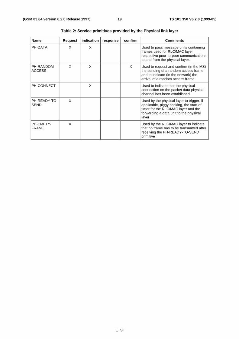
6.5.3 Service Primitives
Table 2 lists the service primitives provided by the Physical Link layer to RLC/MAC layer. More detailed description isgiven in GSM 04.04.
ETSI
TS 101 350 V6.2.0 (1999-05)19(GSM 03.64 version 6.2.0 Release 1997)
Table 2: Service primitives provided by the Physical link layer
Name Request indication response confirm Comments
PH-DATA X X Used to pass message units containingframes used for RLC/MAC layerrespective peer-to-peer communicationsto and from the physical layer.
PH-RANDOMACCESS
X X X Used to request and confirm (in the MS)the sending of a random access frameand to indicate (in the network) thearrival of a random access frame.
PH-CONNECT X Used to indicate that the physicalconnection on the packet data physicalchannel has been established.
PH-READY-TO-SEND
X Used by the physical layer to trigger, ifapplicable, piggy backing, the start oftimer for the RLC/MAC layer and theforwarding a data unit to the physicallayer
PH-EMPTY-FRAME
X Used by the RLC/MAC layer to indicatethat no frame has to be transmitted afterreceiving the PH-READY-TO-SENDprimitive

ETSI
TS 101 350 V6.2.0 (1999-05)20(GSM 03.64 version 6.2.0 Release 1997)
6.5.4 Radio Block Structure
Different Radio Block structures for data transfer and control message transfer purposes are defined. Radio Blockconsists of MAC Header, RLC Data Block or RLC/MAC Control Block. It is always carried by four normal bursts. Fordetailed definition of radio block structure, see GSM 04.60.
MAC header RLC header RLC data
MAC header RLC/MAC Control Message
(part of physical link RLC data block
(part of physical link RLC /MAC control block
Radio Block
Radio Block
Figure 4: Radio Block structures
MAC header contains control fields which are different for uplink and downlink directions. MAC header is constantlength, 8 bits.
RLC header contains control fields which are different for uplink and downlink directions. RLC header is variablelength.
RLC data field contains octets from one or more LLC PDUs.
Block Check Sequence (BCS) is used for error detection.
RLC/MAC Control message field contains one RLC/MAC control message.
6.5.5 Channel Coding
NOTE: The text in this subclause is informative. The normative text is in GSM 05.03 [5]. Where there is aconflict between these descriptions, the normative text has precedence.
Four coding schemes, CS-1 to CS-4, are defined for the packet data traffic channels. For all other packet controlchannels than Packet Random Access Channel (PRACH) and Packet Timing Advance Control Channel on Uplink(PTCCH/U), coding scheme CS-1 is always used. For access bursts on PRACH, two coding schemes are specified.
All coding schemes are mandatory for MSs. Only CS-1 is mandatory for the network.
6.5.5.1 Channel coding for PDTCH
Four different coding schemes, CS-1 to CS-4, are defined for the Radio Blocks carrying RLC data blocks. The blockstructures of the coding schemes are shown Figure 5 and Figure 6.
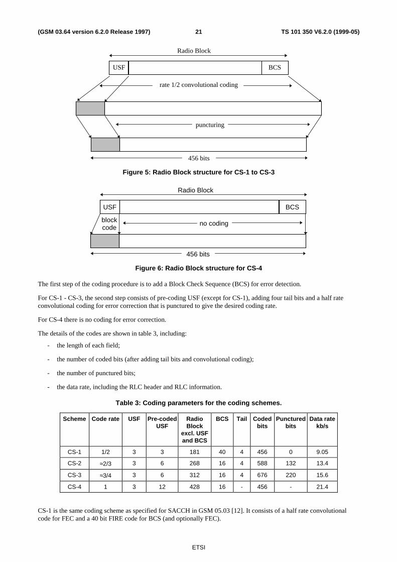
ETSI
TS 101 350 V6.2.0 (1999-05)21(GSM 03.64 version 6.2.0 Release 1997)
rate 1/2 convolutional coding
puncturing
456 bits
USF BCS
Radio Block
Figure 5: Radio Block structure for CS-1 to CS-3
blockcode
no coding
456 bits
USF BCS
Radio Block
Figure 6: Radio Block structure for CS-4
The first step of the coding procedure is to add a Block Check Sequence (BCS) for error detection.
For CS-1 - CS-3, the second step consists of pre-coding USF (except for CS-1), adding four tail bits and a half rateconvolutional coding for error correction that is punctured to give the desired coding rate.
For CS-4 there is no coding for error correction.
The details of the codes are shown in table 3, including:
- the length of each field;
- the number of coded bits (after adding tail bits and convolutional coding);
- the number of punctured bits;
- the data rate, including the RLC header and RLC information.
Table 3: Coding parameters for the coding schemes.
Scheme Code rate USF Pre-codedUSF
RadioBlock
excl. USFand BCS
BCS Tail Codedbits
Puncturedbits
Data ratekb/s
CS-1 1/2 3 3 181 40 4 456 0 9.05
CS-2 ≈2/3 3 6 268 16 4 588 132 13.4
CS-3 ≈3/4 3 6 312 16 4 676 220 15.6
CS-4 1 3 12 428 16 - 456 - 21.4
CS-1 is the same coding scheme as specified for SACCH in GSM 05.03 [12]. It consists of a half rate convolutionalcode for FEC and a 40 bit FIRE code for BCS (and optionally FEC).

ETSI
TS 101 350 V6.2.0 (1999-05)22(GSM 03.64 version 6.2.0 Release 1997)
CS-2 and CS-3 are punctured versions of the same half rate convolutional code as CS-1 for FEC.
CS-4 has no FEC.
CS-2 to CS-4 use the same 16 bit CRC for BCS. The CRC is calculated over the whole uncoded RLC Data Blockincluding MAC Header.
The USF has 8 states, which are represented by a binary 3 bit field in the MAC Header.
For CS-1, the whole Radio Block is convolutionally coded and USF needs to be decoded as part of the data.
All other coding schemes generate the same 12 bit code for USF. The USF can be decoded either as a block code or aspart of the data.
In order to simplify the decoding, the stealing bits (defined in GSM 05.03) of the block are used to indicate the actualcoding scheme.
6.5.5.2 Channel coding for PACCH, PBCCH, PAGCH, PPCH,PNCH and PTCCH
The channel coding for the PACCH, PBCCH, PAGCH, PPCH,PNCH and downlink PTCCH is the same as the codingscheme CS-1 presented in subclause 6.5.5.1.
The coding scheme used for uplink PTCCH is the same as for PRACH.
6.5.5.3 Channel Coding for the PRACH
Two types of packet access burst may be transmitted on the PRACH: an 8 information bits access burst or an 11information bits access burst called the extended packet access burst. The mobile shall support both access bursts. Thechannel coding for both burst formats is indicated in the following subclauses.
6.5.5.3.1 Coding of the 8 data bit Packet Access Burst
The channel coding used for the burst carrying the 8 data bit packet access uplink message is identical to the coding ofthe access burst as defined for random access channel in GSM 05.03.
6.5.5.3.2 Coding of the 11 data bit Packet Access Burst
The channel coding for 11 bit access burst is the punctured version of the same coding as used for 8 bit access burst.
6.5.6 Cell Re-selection
NOTE: The text in this subclause is informative. The normative text is in GSM 03.22 and GSM 05.08. Wherethere is a conflict between these descriptions, the normative text has precedence.
In GPRS Packet Idle and Packet Transfer modes, cell re-selection is performed by the MS, except for a class A MS (seeGSM 02.60) while in dedicated mode in which case the cell is determined by the network according to the handoverprocedures.
The new cell re-selection criteria C31 and C32 are provided as a complement to the current GSM cell re-selectioncriteria. This provides a more general tool to make cell planning for GPRS as similar to existing planning in GSM aspossible.C31 is a signal strength criterion used to decide whether prioritised cell re-selection shall be used. For cells thatfulfil the C31 criterion, the cell with highest priority class shall be selected. If more than one cell has the highest priority,the one of those with the highest C32 value shall be selected. If no cell fulfils the C31 criterion, the one among all cellswith the highest C32 value shall be selected.
C32 is an improvement of C2. It applies an individual offset and hysteresis value to each pair of cells, as well as thesame temporary offsets as for C2. Additional hysteresis values apply for a cell re-selection that requires cell or routingarea update.
Cell re-selection procedure apply to the MSs attached to GPRS if a PBCCH exists in the serving cell. If the PBCCH isnot allocated, then the MS shall perform cell re-selection according to the C2 criteria.

ETSI
TS 101 350 V6.2.0 (1999-05)23(GSM 03.64 version 6.2.0 Release 1997)
In addition, the network may control the cell re-selection as described in subclause 6.5.6.3.
6.5.6.1 Measurements for Cell Re-selection
The MS shall measure the received RF signal strength on the BCCH frequencies of the serving cell and the neighbourcells as indicated in the BA-GPRS list, and calculate the received level average (RLA) for each frequency, as specifiedin GSM 05.08. In addition the MS shall verify the BSIC of the cells. Only channels with the same BSIC as broadcasttogether with BA-GPRS on PBCCH shall be considered for re-selection.
When the number of downlink PDCHs assigned to certain types of multislot MS (see GSM 05.02, annex B) does notallow them to perform measurements within the TDMA frame, the network shall provide measurement windows toensure that the MS can perform a required number of measurements. The network shall provide periods of inactivityduring a fixed allocation to allow the MS to make adjacent cell power measurements and BSIC detection.
6.5.6.2 Broadcast Information
The PBCCH broadcasts GPRS specific cell re-selection parameters for serving and neighbour cells, including the BA(GPRS) list. A BA (GPRS) identifies the neighbour cells, including BSIC, that shall be considered for GPRS cell (re-selection (not necessary the same as for GSM in Idle or circuit switched mode)).
6.5.6.3 Optional measurement reports and network controlled cell re-selection
It shall be possible for the network to order the mobile stations to send measurement reports to the network and tosuspend its normal cell re-selection, and instead to accept decisions from the network. This applies to both Packet idlemode and Packet transfer mode.
The degree to which the mobile station shall resign its radio network control shall be variable, and be ordered in detailby the parameter NETWORK_CONTROL_ORDER [15].
Two sets of parameters are broadcast on PBCCH and are valid in Packet transfer and Packet idle modes respectively.NETWORK_CONTROL_ORDER can also be sent individually to an MS on PACCH, in which case it overrides thebroadcast parameter.
Additionally, the network may request extended measurement reports from the MS and the reporting shall be maintainedin packet idle mode. The reports may include interference measurements (see subclause 6.5.8.3.2). Measurement reportsshall be sent individually from each MS as RLC transmissions. Situations may appear where the network controlled cellre-selection procedures (NC1 or NC2 modes of operation) should not be used:
- When a class A mobile station is simultaneously involved in a circuit switched service and in a GPRS transfer. Inthis case, handover for the circuit switched service has precedence over GPRS network controlled cell re-selection. - When an MS is performing Anonymous Access, cell re-selection implying a change of RouteingArea results in the MS returning to the GPRS MM IDLE state, see GSM 03.60 [3]. Therefore, there might becases where the network controlled cell re-selection would result in the Anonymous Access failing.
In that case, the MS shall stop sending measurement reports and ignore cell change orders.
6.5.7 Timing Advance
NOTE: The text in this subclause is informative. The normative text is in GSM 04.60 and GSM 05.10. Wherethere is a conflict between these descriptions, the normative text has precedence.
The timing advance procedure is used to derive the correct value for timing advance that the MS has to use for theuplink transmission of radio blocks.
The timing advance procedure comprises two parts:
- initial timing advance estimation;
- continuous timing advance update.

ETSI
TS 101 350 V6.2.0 (1999-05)24(GSM 03.64 version 6.2.0 Release 1997)
6.5.7.1 Initial timing advance estimation
The initial timing advance estimation is based on the single access burst carrying the Packet Channel Request. ThePacket Uplink Assignment or Packet Downlink Assignment then carries the estimated timing advance value to the MS.This value shall be used by the MS for the uplink transmissions until the continuous timing advance update provides anew value (see subclause 6.5.7.2.). Two special cases exist:
- when Packet Queuing Notification is used the initial estimated timing advance may become too old to be sent inthe Packet Downlink (/Uplink) Assignment
- when Packet Downlink (/Uplink) Assignment is to be sent without prior paging (i.e., in the Ready state), no validtiming advance value may be available.
Then the network has three options:
- Packet Polling Request can then be used to trigger the transmission of Packet Control Acknowledgement. Thismessage can be formatted as four access burst from which the timing advance can be estimated.
- Packet Downlink (/Uplink) Assignment can be sent without timing advance information. In that case it isindicated to the MS that it can only start the uplink transmission after the timing advance is obtained by thecontinuous timing advance update procedure.
- The poll bit in the Packet Downlink (/Uplink) Assignment message can be set to trigger the transmission ofPacket Control Acknowledgement. This can be used if System information indicates that acknowledgement isaccess bursts.
For the case where timing advance information is not provided in the assignment message, the mobile is not allowed tosend normal bursts on the uplink until it receives a valid timing advance either in Packet Timing Advance/Power Controlmessage or through the continuous timing advance procedure.
6.5.7.2 Continuous timing advance update
MS in Packet transfer mode shall use the continuous timing advance update procedure. The continuous timing advanceupdate procedure is carried on the PTCCH allocated to the MS.
For uplink packet transfer, within the Packet Uplink Assignment, the MS is assigned Timing Advance Index (TAI) andthe PTCCH.
For downlink packet transfer, within the Packet Downlink Assignment, the MS is assigned Timing Advance Index (TAI)and the PTCCH.
The TAI specifies the PTCCH sub-channel used by the MS.
On the uplink, the MS shall send in the assigned PTCCH access burst, which is used by the network to derive the timingadvance.
The network analyses the received access burst and determines new timing advance values for all MSs performing thecontinuous timing advance update procedure on that PDCH. The new timing advance values shall be sent via a downlinksignalling message (TA-message) on PTCCH/D. Network can send timing advance information also in Packet TimingAdvance/Power Control and Packet Uplink Ack/Nack messages on PACCH.

ETSI
TS 101 350 V6.2.0 (1999-05)25(GSM 03.64 version 6.2.0 Release 1997)
6.5.7.2.1 Mapping on the multiframe structure
Figure 7 shows the mapping of the uplink access bursts and downlink TA-messages on groups of eight 52-multiframes:
- the TAI value shows the position where a slot is reserved for a MS to send an access burst (e.g. T1 means 52-multiframe number n and idle slot number 2). TAI value defines the used PTCCH sub-channel.
- every second PDCH multiframe starts a downlink TA-message.
52-multiframe number n:
uplink TAI=0 TAI=1
B0 B1 B2 0 B3 B4 B5 1 B6 B7 B8 2 B9 B10 B11 3
downlink TA_message 1 TA message 1
52-multiframe number n + 1:
uplink TAI=2 TAI=3
B0 B1 B2 4 B3 B4 B5 5 B6 B7 B8 6 B9 B10 B11 7
downlink TA message 1 TA message 1
52-multiframe number n + 2:
uplink TAI=4 TAI=5
B0 B1 B2 8 B3 B4 B5 9 B6 B7 B8 10 B9 B10 B11 11
downlink TA message 2 TA message 2
52-multiframe number n + 3:
uplink TAI=6 TAI=7
B0 B1 B2 12 B3 B4 B5 13 B6 B7 B8 14 B9 B10 B11 15
downlink TA message 2 TA message 2
52-multiframe number n + 4:
uplink TAI=8 TAI=9
B0 B1 B2 16 B3 B4 B5 17 B6 B7 B8 18 B9 B10 B11 19
downlink TA message 3 TA message 3
52-multiframe number n + 5:
uplink TAI=10 TAI=11
B0 B1 B2 20 B3 B4 B5 21 B6 B7 B8 22 B9 B10 B11 23
downlink TA message 3 TA message 3
52-multiframe number n + 6:
uplink TAI=12 TAI=13
B0 B1 B2 24 B3 B4 B5 25 B6 B7 B8 26 B9 B10 B11 27
downlink TA message 4 TA message 4

ETSI
TS 101 350 V6.2.0 (1999-05)26(GSM 03.64 version 6.2.0 Release 1997)
52-multiframe number n + 7:
uplink TAI=14 TAI=15
B0 B1 B2 28 B3 B4 B5 29 B6 B7 B8 30 B9 B10 B11 31
downlink TA message 4 TA message 4
B0 - B11 = Radio blocksIdle frames are numbered from 1 to 31 [odd numbers]PTCCH frames are numbered from 0 to 30 [even numbers]
Figure 7: Mapping of the uplink access bursts and downlink timing advance signalling messages
The BTS shall update the timing advance values in the next TA-message following the access burst. To illustrate this, anMS that transmits an access burst in frames numbered 0, 2, 4, or 6 receives its updated timing advance value in TAmessage 2. This MS can also find this updated timing advance value in subsequent TA messages 3, 4, and 1, but onlyhas to read these if TA message 2 was not received correctly.
An MS entering the Transfer state shall ignore the TA-messages until the MS has sent its first access burst. This is toavoid the use of timing advance values, derived from access bursts sent by the MS that previously used the same TAI.
6.5.8 Power control procedure
Power control shall be supported in order to improve the spectrum efficiency and to reduce the power consumption inthe MS.
For the uplink, the MS shall follow a flexible power control algorithm, which the network can optimise through a set ofparameters. It can be used for both open loop and closed loop power control.
For the downlink, the power control is performed in the BTS. Therefore, there is no need to specify the actualalgorithms, but information about the downlink performance is needed. Therefore the MSs have to transfer ChannelQuality Reports to the BTS.Power control is not applicable to point-to-multipoint multicast services.
For the detailed specification of power control see GSM 05.08.
6.5.8.1 MS output power
The MS shall calculate the RF output power value, PCH, to be used on each individual uplink PDCH assigned to the MS:
PCH = min((Γ0 - ΓCH - α * (C + 48), PMAX)
where
ΓCH is an MS and channel specific power control parameter. It is sent to the MS in any resourceassigning message. Further, the network can, at any time during a packet transfer, send new ΓCH
values to the MS on the downlink PACCH.
Γ0 is a frequency band dependent constant.
α∈[0,1] is a system parameter. Its default value is broadcast on the PBCCH. Further, MS and channelspecific values can be sent to the MS together with ΓCH.
C is the received signal level at the MS.
PMAX is the maximum allowed output power in the cell.
All power values are expressed in dBm.
PCH is not used to determine the output power when accessing the cell on PRACH or RACH , in which case PMAXshall be used.

ETSI
TS 101 350 V6.2.0 (1999-05)27(GSM 03.64 version 6.2.0 Release 1997)
6.5.8.2 BTS output power
The BTS shall use constant power on those PDCH radio blocks which contain PBCCH or which may contain PPCH.This power may be lower than the output power used on BCCH. The difference shall be broadcast on PBCCH.
On the other PDCH radio blocks, downlink power control may be used. Thus, a procedure may be implemented in thenetwork to control the power of the downlink transmission based on the Channel Quality Reports.
The network shall ensure that the output power is sufficient for the MS for which the RLC block is intended as well asthe MS(s) for which the USF is intended, and that for each MS in packet transfer mode, at least one downlink RLCblock per multiframe is transmitted with an output power that is sufficient for that MS, on a block monitored by that MS.
6.5.8.3 Measurements at MS side
A procedure shall be implemented in the MS to monitor periodically the downlink Rx signal level and quality from itsserving cell.
6.5.8.3.1 Deriving the C value
This subclause comprises information about how the MS shall derive the C value in the power control equation.
The MS shall periodically measure the received signal strength.
In packet idle mode, the MS shall measure the signal strength of the PCCCH or, if PCCCH is not existing, the BCCH.
In packet transfer mode, the MS shall measure the signal strength on BCCH. The same measurements as for cell re-selection are used (see 6.5.6.1.). Alternatively, if indicated by a broadcast parameter, the MS shall measure the signalstrength on one of the PDCHs where the MS receives PACCH. This method is suitable in the case where BCCH is inanother frequency band than the used PDCHs. It requires that constant output power is used on all downlink PDCHblocks.
The MS shall measure the signal strength of each radio block monitored by the MS. The C value is achieved by filteringthe signal strength with a running average filter. The filtering shall normally be continuous between the packet modes.The different filter parameters for the packet modes are broadcast on PBCCH or, if PBCCH does not exist, on BCCH.
The variance of the received signal level within each block shall also be calculated. The filtered value SIGN_VAR shallbe included in the channel quality report.
An MS transferring a packet in the uplink with fixed assignment is not required to make signal strength measurementsand shall thus update PCH only when it receives new ΓCH values.
6.5.8.3.2 Derivation of Channel Quality Report
The channel quality is measured as the interference signal level during the idle frames of the multiframe, when theserving cell is not transmitting.
In packet transfer mode, the MS shall measure the interference signal strength of all eight channels (slots) on the samecarrier as the assigned PDCHs.
In packet idle mode, the MS shall measure the interference signal strength on certain channels which are indicated on thePBCCH or, if PBCCH does not exist, on BCCH. If no channels are indicated the MS shall not perform thesemeasurements.
Some of the idle frames and PTCCH frames shall be used for this, while the others are required for BSIC identificationand the timing advance procedure, see subclause 6.5.9.
The MS may not be capable of measuring all eight channels when allocated some configurations of channels. The MSshall measure as many channels as its allocation allows considering its multislot capability.
The slots that the MS measures on can be either idle or used by SACCH or PTCCH, depending on the channel type(TCH or PDCH).. The MS shall therefore, for each slot, take the minimum signal strength of one idle frame and onePTCCH frame. Thus the SACCH frames are avoided (except for a TCH/H with two MSs) and only the interference ismeasured.

ETSI
TS 101 350 V6.2.0 (1999-05)28(GSM 03.64 version 6.2.0 Release 1997)
The interference, γCH , is achieved by filtering the measured interference in a running average filter. The filtering shall becontinuous between the packet modes for channels measured in both modes. The different filter parameters for thepacket modes are broadcast on PBCCH or, if PBCCH does not exist, on BCCH.
In packet transfer mode the MS shall transfer the 8 γCH values and the RXQUAL, SIGN_VAR and C values (seesubclause 6.5.8.3.1) to the network in the Channel Quality Report included in the PACKET DOWNLINK ACK/NACKmessage.
6.5.8.4 Measurements at BSS side
A procedure shall be implemented in the BSS to monitor the uplink Rx signal level and quality on each uplink PDCH,active as well as inactive.
The BSS shall also measure the Rx signal level and the quality of a specific MS packet transfer.
6.5.9 Scheduling the MS activities during the PTCCH and idle frames
The MS shall use the PTCCH and idle frames of the PDCH multiframe for the following tasks:
- BSIC identification for cell re-selection (6.5.6.1)
- Continuous timing advance procedures (6.5.7.2)
- Interference measurements for power control (6.5.8.3.2)
It is not necessary to exactly specify the scheduling of these tasks.
The PTCCH frames used for timing advance signalling is stated in 6.5.7.2.1. During the frames when the MS receivesTA-messages it can also make interference measurements. During the frames when the MS transmits access bursts itmay also be possible to make measurements on some channels.
The MS shall schedule the BSIC identification as efficiently as possible, using the remaining PTCCH frames and theidle frames and also considering the requirements for interference measurements. When the MS is synchronised to aBTS, it knows the timing of the SCH. Therefore, only a few certain frames are required for BSIC identification. In thoseframes it may also be possible to make measurements on some channels. When the MS shall synchronise to a new BTS,it has to prioritise that task. It may then use half of the PTCCH and idle frames, i.e. the same amount as available forcircuit switched connections.
The remaining PTCCH and idle frames shall be used for interference measurements.
6.5.10 Discontinuous Reception (DRX)
NOTE: The text in this subclause is informative. The normative text is in GSM 05.02. Where there is a conflictbetween these descriptions, the normative text has precedence.
DRX (sleep mode) shall be supported when the MS is in Packet Idle mode. DRX is independent from MM states Readyand Standby.
Negotiation of DRX parameters is per MS. An MS may choose to use DRX or not together with some operatingparameters. The following parameters are established:
- DRX/non-DRX indicatorIt indicates whether the MS uses DRX or not.
- DRX periodA conditional parameter for MSs using DRX to determine the right paging group. The DRX period is defined bythe parameter SPLIT_PG_CYCLE.
- Non-DRX timerA conditional parameter for MSs using DRX to determine the time period within which the non-DRX mode iskept after leaving the Transfer state. The support for this feature is optional on the network side and theinformation about the maximum supported value for the timer in the cell is broadcast on PBCCH.

ETSI
TS 101 350 V6.2.0 (1999-05)29(GSM 03.64 version 6.2.0 Release 1997)
An MS in DRX mode is only required to monitor the radio blocks defined by its paging group as definedin GSM 05.02.
Paging group definition based on SPLIT_PG_CYCLE is optional on CCCH for both BTS and MS. If not supported, thedefinition based on BS_PA_MFRMS shall be used. The parameters used to define the paging group for GPRS areshown in the Table 4, together with the corresponding GSM parameters. BS_PCC_CHANS is the number of PDCHscontaining PCCCH.
An MS in non-DRX mode is required to monitor all the radio blocks where PCCCH may be mapped on the PDCHdefined by its paging group.
When page for circuit-switched services is conveyed on PPCH, it follows the same scheduling principles as the page forpacket data. The same is valid for scheduling of resource assignments for downlink packet transfers for MSs in ReadyState (i.e. where no paging is performed).
The MS may need to monitor also PNCH in the case of PTM-M services.
NOTE: Paging reorganisation may be supported in the same way as for circuit switched GSM.
Table 4: Parameters for DRX operation
Parameter GPRS Corresponding GSMparameters
PCCCH CCCH CCCH
DRX period SPLIT_PG_CYCLE BS_PA_MFRMS *)SPLIT_PG_CYCLE **)
BS_PA_MFRMS
Blocks not available forPPCH per multiframe
BS_PAG_BLKS_RES+ BS_PBCCH_BLKS
BS_AG_BLKS_RES BS_AG_BLKS_RES
Number of physical channelscontaining paging
BS_PCC_CHANS BS_CC_CHANS BS_CC_CHANS
*) Only when DRX period split is not supported.**) Only when DRX period split is supported.
6.6 Medium Access Control and Radio Link Control LayerThe Medium Access Control (MAC) and Radio Link Control (RLC) layer operates above the Physical Link layer in thereference architecture. MAC/RLC layer messages and signalling procedures are defined in GSM 04.60 and GSM 04.08.
6.6.1 Layer Services
The MAC function defines the procedures that enable multiple MSs to share a common transmission medium, whichmay consist of several physical channels. The MAC function provides arbitration between multiple MSs attempting totransmit simultaneously and provides collision avoidance, detection and recovery procedures. The operations of theMAC function may allow a single MS to use several physical channels in parallel.
The RLC function defines the procedures for a bitmap selective retransmission of unsuccessfully delivered RLC DataBlocks.
The RCL/MAC function provides two modes of operation:
- unacknowledged operation; and
- acknowledged operation

ETSI
TS 101 350 V6.2.0 (1999-05)30(GSM 03.64 version 6.2.0 Release 1997)
6.6.2 Layer Functions
The GPRS MAC function is responsible for:
- Providing efficient multiplexing of data and control signalling on both uplink and downlink, the control of whichresides on the Network side. On the downlink, multiplexing is controlled by a scheduling mechanism. On theuplink, multiplexing is controlled by medium allocation to individual users (e.g., in response to service request).
- For mobile originated channel access, contention resolution between channel access attempts, including collisiondetection and recovery.
- For mobile terminated channel access, scheduling of access attempts, including queuing of packet accesses.
- Priority handling.
The GPRS RLC function is responsible for:
- Interface primitives allowing the transfer of Logical Link Control layer PDUs (LLC-PDU) between the LLClayer and the MAC function.
- Segmentation and re-assembly of LLC-PDUs into RLC Data Blocks.
- Backward Error Correction (BEC) procedures enabling the selective retransmission of uncorrectable code words.
NOTE: The Block Check Sequence for error detection is provided by the Physical Link Layer.
6.6.3 Service Primitives
Table 5 lists the service primitives provided by the RLC/MAC layer to the upper layers:
Table 5: Service primitives provided by the RLC/MAC layer to the upper layers
Name request indication response confirm comments
RLC/MAC-DATA x x used for the transfer of upper layer PDUs.Acknowledged mode of operation in RLCis used. The upper layer shall be able torequest high transmission quality via aprimitive parameter.
RLC/MAC-UNITDATA
x x used for the transfer of upper layer PDUs.Unacknowledged mode of operation inRLC is used.
RLC/MAC-STATUS x used to indicate that an error has occurredon the radio interface. The cause for thefailure is indicated.
6.6.4 Model of Operation
Each PDCH is a shared medium between multiple MSs and the Network. Direct communication is possible onlybetween an MS and the network.
The GPRS radio interface consists of asymmetric and independent uplink and downlink channels. The downlink carriestransmissions from the network to multiple MSs and does not require contention arbitration. The uplink is shared amongmultiple MSs and requires contention control procedures.
The allocation of radio resources by the PLMN and the use of these resources by the MSs can be broken down into twoparts:
- The PLMN allocates radio resources for the GPRS (uplink and downlink) in a symmetric manner.

ETSI
TS 101 350 V6.2.0 (1999-05)31(GSM 03.64 version 6.2.0 Release 1997)
- The allocated uplink and downlink radio resources for point-to-point, point-to-multipoint multicast or group callservice types are used independently of each other. Dependent allocation of uplink and downlink shall bepossible, in order to allow simple MSs to transfer data simultaneously in both directions. Allocation of severalPDTCHs for one MS is possible.
The access to the GPRS uplink uses a Slotted-Aloha based reservation protocol.
The Network Protocol Data Units (N-PDU) are segmented into the Subnetwork Protocol Data Units (SN-PDU) by theSubnetwork Dependent Convergence (SNDC) protocol and SN-PDUs are encapsulated into one or several LLC frames.See GSM 03.60 [3] for information on SNDC and LLC. The details on SNDC can be found in GSM 04.65 [9] and thedetails on LLC can be found in GSM 04.64 [8]. LLC frames are segmented into RLC Data Blocks. At the RLC/MAClayer, a selective ARQ protocol (including block numbering) between the MS and the Network provides retransmissionof erroneous RLC Data Blocks. When a complete LLC frame is successfully transferred across the RLC layer, it isforwarded to the LLC layer.
Normal burst Normal burst Normal burst Normal burst
BH
FH
LLClayer
RLC/MAClayer
Physicallayer
Information field FCS
Info fieldBH BCSRLCblocks
LLCframe
Primaryblock
Followingblock
Info field BCS Info field BH BCS
FH = Frame HeaderFCS =BH =BCS = Block Check Sequence
Frame Check SequenceBlock Header
Figure 8: Transmission and reception data flow
6.6.4.1 Uplink State Flag
The Uplink State Flag (USF) is used on PDCH to allow multiplexing of Radio blocks from a number of MSs. USF isused in dynamic and extended dynamic medium access modes. USF is used only in downlink direction.
The USF comprises 3 bits at the beginning of each Radio Block that is sent on the downlink. It enables the coding of 8different USF states which are used to multiplex the uplink traffic.
On PCCCH, one USF value is used to denote PRACH. The other USF values are used to reserve the uplink for differentMSs. On PDCHs not carrying PCCCH, the eight USF values are used to reserve the uplink for different MSs. One USFvalue shall be used to prevent collision on uplink channel, when MS without USF is using uplink channel. The USFpoints either to the next uplink Radio Block or the sequence of 4 uplink Radio Blocks starting with the next uplinkRadio Block.
6.6.4.2 Temporary Block Flow
A Temporary Block Flow (TBF) is a physical connection used by the two RR entities to support the unidirectionaltransfer of LLC PDUs on packet data physical channels. The TBF is allocated radio resource on one or more PDCHsand comprise a number of RLC/MAC blocks carrying one or more LLC PDUs. A TBF is temporary and is maintainedonly for the duration of the data transfer.
ETSI
TS 101 350 V6.2.0 (1999-05)32(GSM 03.64 version 6.2.0 Release 1997)
6.6.4.3 Temporary Flow Identity
Each TBF is assigned a Temporary Flow Identity (TFI) by the network. The assigned TFI is unique among concurrentTBFs in each directions and is used instead of the MS identity in the RLC/MAC layer. The same TFI value may be usedconcurrently for TBFs in opposite directions. The TFI is assigned in a resource assignment message that precedes thetransfer of LLC frames belonging to one TBF to/from the MS. The same TFI is included in every RLC header belongingto a particular TBF as well as in the control messages associated to the LLC frame transfer (e.g. acknowledgements) inorder to address the peer RLC entities.
6.6.4.4 Medium Access modes
Three medium access modes are supported:
- Dynamic allocation;
- Extended Dynamic allocation; and
- Fixed allocation
The Dynamic allocation medium access mode or Fixed allocation medium access mode shall be supported by allnetworks that support GPRS. The support of Extended Dynamic allocation is optional.
The Dynamic allocation and Fixed allocation modes shall be supported in all mobile stations.
6.6.4.5 Acknowledged mode for RLC/MAC operation
The transfer of RLC Data Blocks in the acknowledged RLC/MAC mode is controlled by a selective ARQ mechanismcoupled with the numbering of the RLC Data Blocks within one Temporary Block Flow. The sending side (the MS orthe network) transmits blocks within a window and the receiving side sends Packet Uplink Ack/Nack or PacketDownlink Ack/Nack message when needed. Every such message acknowledges all correctly received RLC Data Blocksup to an indicated block sequence number (BSN), thus “moving” the beginning of the sending window on the sendingside. Additionally, the bitmap that starts at the same RLC Data Block is used to selectively request erroneously receivedRLC Data Blocks for retransmission. The sending side then retransmits the erroneous RLC Data Blocks, eventuallyresulting in further sliding the sending window.
The Packet Ack/Nack message does not include any change in the current assignment (and thus does not have to beacknowledged when sent on downlink). A missing Packet Ack/Nack is not critical and a new one can be issuedwhenever. In Packet Downlink Ack/Nack message, the MS may optionally initiate an uplink TBF or request a temporarysuspension of the downlink TBF. In Packet Uplink Ack/Nack message , the network can assign uplink resources formobile station using a fixed allocation.
When receiving uplink data from a MS the network shall, based on erroneous blocks received from MS, allocateadditional resources for retransmission.
The acknowledgement procedure of the LLC layer is not combined with the acknowledgement procedure on theunderlying RLC/MAC layer.
6.6.4.6 Unacknowledged mode for RLC/MAC operation
The transfer of RLC Data Blocks in the unacknowledged RLC/MAC mode is controlled by the numbering of the RLCData Blocks within one Temporary Block Flow and does not include any retransmissions. The receiving side extractsuser data from the received RLC Data Blocks and attempts to preserve the user information length by replacing missingRLC Data Blocks by dummy information bits.
The same mechanism and message format for sending temporary acknowledgement messages is used as foracknowledged mode in order to convey the necessary control signalling (e.g. monitoring of channel quality for downlinkchannel or timing advance correction for uplink transfers). The fields for denoting the erroneous RLC blocks may beused as an additional measure for channel quality (i.e. parameter for link adaptation). The sending side (the MS or thenetwork) transmits a number of radio blocks and then polls the receiving side to send an acknowledgement message.The Packet Uplink Ack/Nack/Packet Downlink Ack/Nack message does not include any change in the currentassignment. A missing acknowledgement message is not critical and a new one can be obtained whenever.

ETSI
TS 101 350 V6.2.0 (1999-05)33(GSM 03.64 version 6.2.0 Release 1997)
6.6.4.7 Mobile Originated Packet Transfer
6.6.4.7.1 Uplink Access
Network
Packet Channel Request
Packet Uplink Assignment
Packet Resource Request
Packet Uplink Assignment
PRACH (or RACH )
PAGCH (or AGCH )
PACCH
PACCH
(Optional)
(Optional)
Figure 9: Access and allocation for the one or two phase packet access, uplink packet transfer
An MS initiates a packet transfer by making a Packet Channel Request on PRACH or RACH. The network responds onPAGCH or AGCH respectively. It is possible to use one or two phase packet access method (see Figure 9).
In the one phase access, the Packet Channel Request is responded by the network with the Packet Uplink Assignmentreserving the resources on PDCH(s) for uplink transfer of a number of Radio blocks. The reservation is doneaccordingly to the information about the requested resources that is comprised in the Packet Channel Request. OnRACH, there is only two cause values available for denoting GPRS, which can be used to request limited resources ortwo phase access. On PRACH, the Packet Channel Request may contain more adequate information about the requestedresources and, consequently, uplink resources on one or several PDCHs can be assigned by using the Packet UplinkAssignment message.
In the two phase access, the Packet Channel Request is responded with the Packet Uplink Assignment which reservesthe uplink resources for transmitting the Packet Resource Request. A two phase access can be initiated by the network ora mobile station. The network can order the MS to send Packet Resource Request message by setting parameter inPacket Uplink Assignment message. Mobile station can require two phase access in Packet Channel Request message. Inthis case, the network may order MS to send Packet Resource Request or continue with a one phase access procedure.
The Packet Resource Request message carries the complete description of the requested resources for the uplinktransfer. The MS can indicate the medium access method, it prefers to be used during the TBF. The network respondswith the Packet Uplink Assignment reserving resources for the uplink transfer and defining the actual parameters fordata transfer (e.g. medium access mode).
If there is no response to the Packet Channel Request within predefined time period, the MS makes a retry after arandom backoff time.
On PRACH there is used a 2-step approach including a long-term and a short-term estimation of the persistence (seeFigure 10). The optimal persistence of the mobile stations is calculated at the network side.

ETSI
TS 101 350 V6.2.0 (1999-05)34(GSM 03.64 version 6.2.0 Release 1997)
accesscontrol
decoding ofparameters
persistence control
short-termestimation
accessanalysis
long-termestimation
persistenceinstruction
set P
contentionlevelsρ(i)
access(priority i)
networkside
mobilestation
Figure 10: Basic principle of random access traffic control
The actual persistence values depend on:
- the priority i of the packet to be transmitted;
- the amount of traffic within higher priority classes;
- the amount of traffic within the own priority class.
Optionally, the existing backoff algorithm on RACH can be used on PRACH.
On RACH, the existing backoff algorithm shall be used.
Occasionally, more Packet Channel Requests can be received than can be served. To handle this, a Packet QueuingNotification is transmitted to the sender of the Packet Channel Request. The notification includes information that thePacket Channel Request message is correctly received and Packet Immediate Assignment may be transmitted later. If theTiming Advance information becomes inaccurate for an MS, the network can send Packet Polling Request to trigger theMS to send four random access bursts. This can be used to estimate the new Timing Advance before issuing the PacketUplink Assignment.
6.6.4.7.2 Dynamic/Extended Dynamic allocation
6.6.4.7.2.1 Uplink Packet Transfer
The Packet Uplink Assignment message includes the list of PDCHs and the corresponding USF value per PDCH. Aunique TFI is allocated and is thereafter included in each RLC Data and Control Block related to that Temporary BlockFlow. The MS monitors the USFs on the allocated PDCHs and transmits Radio blocks on those which currently bear theUSF value reserved for the usage of the MS.
If the resource assigned by the network in the case of extended dynamic allocation does not allow the multislot MS (seeGSM 05.02, annex B) to monitor the USF on all the assigned PDCHs, the following rules shall apply:
- Whenever the MS receives its USF on one downlink PDCH (e.g. on timeslot 0 while timeslots 0, 2 and 3 wereassigned), it shall consider the corresponding uplink block and all subsequent ones from the list of assignedPDCHs as allocated (e.g. on 0, 2 and 3). Hence, if the network allocates a block to this MS on an assignedPDCH, it shall also allocate blocks to this MS on all subsequent PDCHs in the list. For each allocated block, thenetwork shall set the USF to the value reserved for the usage of that MS. These rules apply on a block periodbasis.

ETSI
TS 101 350 V6.2.0 (1999-05)35(GSM 03.64 version 6.2.0 Release 1997)
- During block periods where it is transmitting, the MS shall monitor the USF on each PDCH in the list of assignedPDCHs, up to and including the first PDCH currently used for transmission. This rule applies on a block periodbasis. For example, if timeslots 0, 2 and 3 have been assigned and blocks are currently allocated on timeslots 2and 3, then during this block period the MS monitors USF on timeslots 0 and 2. If the reserved value of USF isfound on timeslot 0, then the next allocated blocks shall be on timeslots 0, 2 and 3. If the reserved value of USFis found on timeslot 2, then the next allocated blocks shall be on timeslots 2 and 3. And so on for the subsequentblock periods. Because each Radio Block includes an identifier (TFI), all received Radio blocks are correctlyassociated with a particular LLC frame and a particular MS, thus making the protocol highly robust. By alteringthe state of USF, different PDCHs can be "opened" and "closed" dynamically for certain MSs thus providing aflexible reservation mechanism. Additionally, packets with higher priority and pending control messages cantemporarily interrupt a data transmission from one MS.
The channel reservation algorithm can also be implemented on assignment basis. This allows individual MSs to transmita predetermined amount of time without interruptions.
The MS may be allowed to use the uplink resources as long as there is queued data on the RLC/MAC layer to be sentfrom the MS. It can comprise a number of LLC frames. In that sense the radio resources are assigned on the initially“unlimited” time basis. Alternatively, the uplink assignment for each assignment may be limited to a number of radioblocks (e.g. in order to offer more fair access to the medium at higher loads).
The selective ARQ operation for the acknowledged RLC/MAC mode is described in Subclause 6.6.4.5. Theunacknowledged RLC/MAC mode operation is described in Subclause 6.6.4.6.
Figure 11 shows an example of message sequence for the (multislot) uplink data transfer with one resource reallocationand possible RLC Data Block re-transmissions.
Packet Uplink Ack/Nack
Data Block (last)
Access and Assignment
MS Network
PDTCH
PACCH
PDTCH
Packet Uplink Assignment
Packet Control AcknowledgementPACCH
PACCH
Data BlockPDTCH
Data BlockPDTCH
Data Block (last in send window)PDTCH
Data BlockPDTCH
Data BlockPDTCH
Data BlockPDTCH
Data BlockPDTCH
Packet Uplink Ack/Nack (final) PACCH
Figure 11: An example of dynamic allocation uplink data transfer
6.6.4.7.2.2 Release of the Resources
The release of the resources is normally initiated from the MS by counting down the last couple of blocks).
ETSI
TS 101 350 V6.2.0 (1999-05)36(GSM 03.64 version 6.2.0 Release 1997)
For the normal release of resources for RLC connection carrying a mobile originated packet transfer, the mechanismbased on acknowledged final Packet Uplink Ack/Nack combined with timers is used.
After the MS has sent its last RLC Data Block (indicated by the countdown field), the acknowledgement is expectedfrom the network side. By sending the last block, the MS may no longer use the same assignment unless a negativeacknowledgement arrives. It also means that the network side may reallocate the same USF(s) to some other user assoon as all the RLC Data Blocks belonging to that Temporary Block Flow are correctly received; that regardless of thepossible later errors in the acknowledgements.
The next step, in the case of all RLC Data Blocks being correctly received, is that the network sends Packet Ack/Nackwhich is to be immediately acknowledged in the reserved uplink block period. It must be possible for the network not touse the mechanism of acknowledgement for Packet Ack/Nack in which case the release of the resources procedure reliesonly on timers. The TFI can be reused for another assignment either upon the reception of the acknowledgement forPacket Ack/Nack or after expiry of the guard timer.
Further, the premature release or change of assignment for one MS can be initiated by the network. In the case ofrelease, the MS is ordered to interrupt the Temporary Block Flow. The MS shall then reorganise the uplink buffer andissue a new Packet Channel Request to continue the uplink transfer with the RLC Data Blocks containing untransferred(i.e. on the RLC/MAC layer unacknowledged) LLC frames. In the case of the change in assignment, the Packet UplinkAssignment message is issued.
6.6.4.7.3 Fixed Allocation
Fixed allocation uses the Packet Uplink Assignment message to communicate a detailed fixed uplink resource allocationto the MS. The fixed allocation consists of a start frame, slot assignment, and block assignment bitmap representing theassigned blocks per timeslot. The MS waits until the start frame indicated and then transmits radio blocks on thoseblocks indicated in the block assignment bitmap. The fixed allocation does not include the USF and the MS is free totransmit on the uplink without monitoring the downlink for the USF. Unused USF value is used to prevent other mobilesto transmit. If the current allocation is not sufficient, the MS may request additional resources in one of the assigneduplink blocks. A unique TFI is allocated and is thereafter included in each RLC data and control block related to thatTemporary Block Flow. Because each Radio Block includes an identifier (TFI), all received Radio blocks are correctlyassociated with a particular LLC frame and a particular MS.
The number of blocks an MS requests in the initial and subsequent allocation request messages shall only account forthe number of data and control blocks it intends to send. The MS shall not request additional blocks for theretransmission of erroneous blocks. The network can repeat the allocation of radio resources by sending the PacketUplink Assignment or the Packet Uplink Ack/Nack message with a Repeat Allocation field to the MS.
The selective ARQ operation for the acknowledged RLC/MAC mode is described in Subclause 6.6.4.5. Theunacknowledged RLC/MAC mode operation is described in Subclause 6.6.4.6.
Figure 11 shows an example of message sequence for the (multislot) uplink data transfer with one resource reallocationand possible RLC Data Block re-transmissions.
6.6.4.7.4 Contention Resolution
Contention resolution is an important part of RLC/MAC protocol operation, especially because one channel allocationcan be used to transfer a number of LLC frames. Contention resolution applies for both dynamic and fixed allocationmedium access modes.
There are two basic access possibilities, one phase and two phase access as defined in Subclause 6.6.4.7.1.
The two phase access is inherently immune for possibility that two MSs can perceive the same channel allocation astheir own. Namely the second access phase, the Packet Resource Request, uniquely identifies the MS by its TLLI. Thesame TLLI is included in the Packet Uplink Assignment/Packet Downlink Assignment and no mistake is possible.
The one phase access is somewhat insecure and an efficient contention resolution mechanism has to be introduced.
The first part of the solution is the identification of the MS. The identification of transmitting MS on the RLC/MAClevel is necessary not only for contention resolution but also to be able to establish RLC protocol entity for thatTemporary Block Flow on the network side. Additionally, the TLLI is necessary to be able to match simultaneous uplinkand downlink packet transfers by taking into consideration multislot capability of that MS.

ETSI
TS 101 350 V6.2.0 (1999-05)37(GSM 03.64 version 6.2.0 Release 1997)
In order to uniquely identify the MS when sending on uplink, the RLC Header for the first three RLC Data Blocks onuplink is extended to include the TLLI.
The second part of the solution is the notification from the network side about who owns the allocation. That is solvedby the inclusion of the TLLI in the Packet Uplink Ack/Nack/Packet Downlink Ack/Nack. This message can be sent in anearly stage, even before the receive window for RLC/MAC protocol operation is full. By doing so, the contention isresolved after the first occurrence of Packet Ack/Nack. The possibility of RLC Data Blocks being captured from“wrong” MS, thus destroying the LLC frame, shall be covered for by retransmissions on the LLC layer.
6.6.4.8 Mobile Terminated Packet Transfer
6.6.4.8.1 Packet Paging
The network initiates packet transfer to an MS that is in Standby state by sending a Packet Paging Request on thedownlink PPCH or PCH. The MS responds to the Packet Paging Request by initiating a procedure for page response.The RLC/MAC Packet Paging Response message contains TLLI, as well as a complete LLC frame including also TLLI(see Figure 12). The message sequence described in Figure 12 below is conveyed either on PCCCH or on CCCH. Afterthe Packet Paging Response, the mobility management state of the MS is Ready.
Network
Packet Channel Request
Packet Downlink AssignmentAssignmentPacket Paging Response (LLC frame)
PRACH or RACH
PAGCH (or AGCH )
PACCH
PPCH or PCHPacket Paging Request
(
(
)
)
Figure 12: Paging message sequence for Paging, downlink packet transfer
6.6.4.8.2 Downlink Packet Transfer
Transmission of a packet to an MS in the Ready state is initiated by the network using the Packet Downlink Assignmentmessage. In case there is PCCCH allocated in the cell, the Packet Downlink Assignment is transmitted on PAGCH. Incase there is no PCCCH allocated in the cell, the Immediate Assignment is transmitted on AGCH. The Packet DownlinkAssignment message includes the list of PDCH(s) that will be used for downlink transfer. The Timing Advance andPower Control information is also included, if available. Otherwise, the MS may be requested to respond with an PacketControl Acknowledgement (see also Subclause 6.5.7 on timing advance procedures). The MS multislot capability needsto be considered.
The network sends the Radio blocks belonging to one Temporary Block Flow on downlink on the assigned downlinkchannels.
Multiplexing the Radio blocks destined for different MSs on the same PDCH downlink is enabled with an identifier, e.g.TFI, included in each Radio Block. The interruption of data transmission to one MS is possible.
The acknowledged (i.e. selective ARQ operation) and unacknowledged RLC/MAC mode operation is described inSubclauses 6.6.4.5 and 6.6.4.6. The sending of Packet Downlink Ack/Nack is obtained by the occasional networkinitiated polling of the MS. The MS sends the Packet Downlink Ack/Nack message in a reserved Radio Block which isallocated together with polling. Unassigned USF value is used in the downlink Radio Block which corresponds to thereserved uplink Radio blocks. Further, if the MS wants to send some additional signalling or uplink data, it may beindicated in the Packet Downlink Ack/Nack message.
Figure 13 shows an example of message sequence for (multislot) downlink data transfer with one resource reallocationand possible RLC Data Block re-transmissions.

ETSI
TS 101 350 V6.2.0 (1999-05)38(GSM 03.64 version 6.2.0 Release 1997)
Packet Downl ink Ack/Nack
Access and Assignment
MS Network
P D T C H
P A C C H
Packet Downl ink Ass ignment
Packet Contro l AcknowledgementP A C C H
P A C C H
P A C C HPacket Downl ink Ack/Nack (final)
Data BlockP D T C H
Data BlockP D T C H
Data Block (pol l ing) P D T C H
Data BlockP D T C H
Data BlockP D T C H
Data BlockP D T C H
Data BlockP D T C H
Data BlockP D T C H
Data Block ( last, pol l ing)P A C C H
Figure 13: An example of downlink data transfer
6.6.4.8.3 Release of the Resources
The release of the resources is initiated by the network by terminating the downlink transfer and polling the MS for afinal Packet Downlink Ack/Nack.
It is possible for the network to change the current downlink assignment by using the Packet Downlink Assignmentwhich then has to be acknowledged by the MS in an immediate reserved block period on the uplink.
The handling of TFI is steered with the same timer that runs on both the MS and the network side after the last RLCData Block is sent to the MS. When it expires, the current assignment becomes invalid for the MS and TFI can bereused by the network. Further, TFI may be reused already upon the reception of the final Packet Downlink Ack/Nackfrom the MS.
6.6.4.9 Simultaneous Uplink and Downlink Packet Transfer
During the ongoing uplink Temporary Block Flow, the MS continuously monitors one downlink PDCH for possibleoccurrences of Packet Downlink Assignment messages on PACCH (see Figure 11). The MS is therefore reachable fordownlink packet transfers that can then be conveyed simultaneously on the PDCH(s) that respect the MS multislotcapability.
If the MS wants to send packets to the network during the ongoing downlink Temporary Block Flow, it can be indicatedin the acknowledgement that is sent from the MS. By doing so, no explicit Packet Channel Requests have to be sent tothe network. Further, the network already has the knowledge of which PDCH(s) that particular MS is currently using sothat the uplink resources can be assigned on the PDCH(s) that respect the MS multislot capability. This method mayintroduce an extra delay when initiating the uplink packet transfer but only for the first LLC frame in a sequence.
ETSI
TS 101 350 V6.2.0 (1999-05)39(GSM 03.64 version 6.2.0 Release 1997)
6.7 Abnormal cases in GPRS MS Ready StateThe RLC/MAC error causes and procedures to handle these can be found in GSM 04.08, 04.60 and 05.08.
6.8 PTM-M Data TransferNOTE: The stage 3 specification for PTM-M data transfer is left for phase 2 of GPRS specification.
PTM-M data, in the form of individual LLC frames, is mapped into RLC/MAC-PTM_DATA primitive and distributedfrom SGSN to the BSS representing the cells that are defined by a geographical area parameter. To the cells concerned,the BSS for each PTM-M LLC frame:
- Optionally, sends a “PTM-M new message” indicator on all individual paging channels on PCCCH if allocated,otherwise on CCCH. The indication refers to a PTM-M notification channel PNCH on PCCCH or NCH onCCCH, where a notification for the new PTM-M message can be received.
If the indicator option is not supported, or if an MS can not receive the indicator when expected, e.g. because thecorresponding block in the multiframe structure is used for other purposes than paging, the MS must read thenotification channel.
- Sends a PTM-M notification on PNCH or NCH. The notification has the form of a Packet Resource Assignmentfor the PTM-M LLC frame. The notification includes a group identity IMGI, a unique LLC frame identifier (inthe form of an N-PDU number together with a segment offset, see GSM 04.65) and an allocation of a TFI to beused in all RLC blocks of the LLC frame.
- Transmits the PTM-M LLC frame on the assigned downlink resources.
Transfer of PTM-M data is carried out without any ARQ on the RLC/MAC and LLC layers. Instead, each LLC frame isretransmitted a specified number of times. For each retransmission, the above procedure is performed. The PTM-Mnotification (resource assignment) includes the unique LLC frame identifier as in the first transmission but a newallocation of TFI.
An MS accumulates correctly received RLC blocks from each transmission to assemble an LLC frame.
The dimensioning of PNCH shall be scaleable depending on capacity requirements.
An NCH may, if capacity allows, be used as a shared notification channel for PTM-M and Advanced Speech Call Items(ASCI).
An MS only interested in PTM-M needs to listen only to PNCH/NCH.

ETSI
TS 101 350 V6.2.0 (1999-05)40(GSM 03.64 version 6.2.0 Release 1997)
Annex A (informative):Bibliography
1) ITU-T I.130, Method for the Characterization of Telecommunication Services Supported by anISDN
2) ITU-T Q.65, Stage 2 of the Method for Characterization of the Services Supported by an ISDN
3) DIS 8886, OSI Data Link Service Definition
4) DIS 10022, OSI Physical Service Definition
5) ISO 10039, Medium Access Control Service Definition
6) ISO 4335, HDLC Procedures
7) ISO 7478, Multilink Procedures
8) ISO 7498, OSI Basic Reference Model and Layer Service Conventions

ETSI
TS 101 350 V6.2.0 (1999-05)41(GSM 03.64 version 6.2.0 Release 1997)
Annex B (informative):Document change history
SPEC SMG# CR PHA VERS NEW_VER SUBJECT03.64 s22 NEW 2+ 2.1.1 5.0.0 GSM 03.64 GPRS Stage 2 Radio03.64 s23 A022 R97 5.0.0 5.1.0 Unacknowledged mode of RLC/MAC operation03.64 s23 A023 R97 5.0.0 5.1.0 Improved RLC Service Primitives03.64 s23 A024 R97 5.0.0 5.1.0 Enhancements to dynamic allocation03.64 s23 A025 R97 5.0.0 5.1.0 Clarifications to DRX03.64 s23 A026 R97 5.0.0 5.1.0 Optimisation for network control cell reselection03.64 s23 A027 R97 5.0.0 5.1.0 Abnormal Cases in GPRS MS Ready State: Leaky Bucket
Procedure03.64 s23 A029 R97 5.0.0 5.1.0 Multiframe structure (details) (revision of SMG2 GPRS 301/97)03.64 s23 A030 R97 5.0.0 5.1.0 Abnormal Cases in GPRS MS Ready State03.64 s23 A031 R97 5.0.0 5.1.0 Cell Re-Selection in GPRS03.64 s23 A032 R97 5.0.0 5.1.0 Definition of PACCH03.64 s23 A033 R97 5.0.0 5.1.0 Clarifications on Timing advance procedure03.64 s23 A035 R97 5.0.0 5.1.0 Bit order for USF coding in GPRS03.64 s23 A036 R97 5.0.0 5.1.0 PTM-M03.64 s23 A037 R97 5.0.0 5.1.0 Contention resolution03.64 s23 A039 R97 5.0.0 5.1.0 Deleting parameter XHYST03.64 s24 A031 R97 5.1.0 5.2.0 Clarification on the use of hysteresis for cell re-selection03.64 s25 A043 R97 5.2.0 6.0.0 Clarification of the use of TAI03.64 s25 A049 R97 5.2.0 6.0.0 USF granularity for dynamic allocation03.64 s26 R97 6.0.0 6.0.1 Editorial changes for Publication03.64 s27 A050 R97 6.0.1 6.1.0 Changes on all chapters to align the spec. with other GPRS
specifications.03.64 s27 A044 R97 6.0.1 6.1.0 Clarification on PACCH allocation for fixed assignment03.64 s28 A052 R97 6.1.0 6.2.0 PBCCH scheduling and editorial corrections
03.64 s28 A051 R97 6.1.0 6.2.0 Interference measurements on network control
03.64 s28 A053 R97 6.1.0 6.2.0 51-multiframe PBCCH

ETSI
TS 101 350 V6.2.0 (1999-05)42(GSM 03.64 version 6.2.0 Release 1997)
History
Document history
V6.0.1 August 1998 Publication
V6.1.0 October 1998 Publication
V6.2.0 May 1999 Publication
ISBN 2-7437-3089-7Dépôt légal : Mai 1999