General Metal Work (pdf, 2.03 MB)
90
General Metal Work
Transcript of General Metal Work (pdf, 2.03 MB)

General Metal Work

Table of ContentsGeneral Metal Work...........................................................................................................................................1
GENERAL SURVEY...............................................................................................................................11. METALS AND THEIR PROPERTIES.................................................................................................5
1.1 Classification of Metals..............................................................................................................51.2 Identification of Metals (Examples)............................................................................................51.3 Properties of Metals...................................................................................................................71.4 Shapes and Sizes of Metal......................................................................................................11
2. TECHNICAL DRAWING...................................................................................................................122.1 Introduction into Technical Drawing.........................................................................................122.2 Types of Lines..........................................................................................................................132.3 Drawing Paper with title block..................................................................................................142.4 Basic Rules..............................................................................................................................162.5 Drawing in three Elevations.....................................................................................................19
3. METROLOGY...................................................................................................................................203.1 Metric System..........................................................................................................................203.2 Inch System.............................................................................................................................223.3 Metrology Introduction..............................................................................................................223.4 Common Measuring Tasks......................................................................................................223.5 Measuring Equipment..............................................................................................................23
4. FITS AND ISO TOLERANCES.........................................................................................................335. LAYING OUT....................................................................................................................................36
5.1 Layout Tools and Accessories.................................................................................................365.2 Layout Procedure.....................................................................................................................37
6. BENCH WORK TOOLS....................................................................................................................396.1 Work Bench..............................................................................................................................406.2 Bench Vise...............................................................................................................................406.3 Hand Hacksaw.........................................................................................................................416.4 Chisel Tools.............................................................................................................................426.5 Files..........................................................................................................................................436.6 Hammer...................................................................................................................................46Bench Work Exercise.....................................................................................................................47Bench Work Exercise − New..........................................................................................................53
7. PRINCIPLES OF MECHANICAL METAL CUTTING........................................................................607.1 Classification of Metal Cutting Processes................................................................................607.2 Angles of tools..........................................................................................................................607.3 Cutting Tool Guideline..............................................................................................................62
8. DRILLING.........................................................................................................................................628.1 Drill Press.................................................................................................................................628.2 Twist drill..................................................................................................................................648.3 Different Drill Press Operations................................................................................................688.4 Facts and Problems.................................................................................................................698.5 Drill Press Safety......................................................................................................................70
9. CUTTING THREADS WITH TAP & DIES.........................................................................................719.1 Main Parts of a Screw Thread..................................................................................................719.2 Hand Tapping...........................................................................................................................719.3 Threading Dies.........................................................................................................................74
10. SHARPENING TOOLS...................................................................................................................7610.1 Bench Grinder or Pedestal Grinder........................................................................................7610.2 Sharpening Tools...................................................................................................................7710.3 Safety Precautions:................................................................................................................78
LIST OF NEEDED RESSOURCES FOR “GENERAL METAL” COURSE...........................................7811. APPENDIX......................................................................................................................................79
APPENDIX NO. 1...........................................................................................................................79APPENDIX NO. 2...........................................................................................................................80
GENERAL METAL WORK − FINAL TEST...........................................................................................81
i

ii

General Metal Work
With technical assistance from:GERMAN DEVELOPMENT SERVICE
August 2000
Dear Reader,
I would like to comment this handout, because otherwise you might get a little confused while studying it.
The most important thing to know is, that this handout is developed for a non−formal Training Center. Theparticipating government officials and the involved companies were not interested in long−term courses. So, Ihad to respect the wish of my project partners for a course with this length and was limited on the mostimportant subjects.
One or two of the modules are still under construction. Sorry for this.
DED − Development Worker
GENERAL SURVEY
TARGET PARTICIPANTS
• min 18 years old, High school graduates, no experience needed
LENGTH OF COURSE
120 hours / 15 days
OBJECTIVES
At the end of the course, the participants should be able to:
• Distinguish different metals and their properties and know the most common shapes ofmetals
• Read and draft simple blue prints in order to fabricate workpieces to the requiredspecification
• Know how to measure, use the most important measuring tools and prevent the mostcommon mistakes while measuring
• Understand the importance of limits and fits in fabrication and know how to use them
• Lay out some workpieces with the necessary tools
• Understand the basics of angles of cutting tools
• Properly use hand hacksaw, file, chisel, hammer and other hand tools
• Know the process of drilling with a drill press and the needed tools and equipment
• Know how to sharpen tools using the bench grinder
• Cut internal and external threads with taps and dies and know how to prepare the workpiece
1

• Make use of different power tools typically used in a metal workshop
• Know how to use SMAW welding machine while welding mild steel
• Cut metals with Oxy−Acetylene cutting outfit
• Know and use the proper safety procedures and equipment
COURSE OUTLINE
THEORY (30%) HANDS−ON TRAINING (70%) METHOD
• Metals and their properties• Various types of drawings,scales, views, lines, symbols ofblue prints• Measuring tools and measuringerrors.• Metric and inch system• Procedure of laying out• Limits and fits• Principles of metal cutting andcutting angles of tools• Bench and hand tools• Drilling operation, threading andreaming• Sharpening tools using benchgrinder• Cutting and grinding with powertools• SMAW welding process• Oxy−Acetylene cutting• Safety procedures andequipment
• Draw and read some simple drawings• Use measuring tools like steel rule, verniercalibers, micrometer, protractor• Use laying out tools like scriber, divider, centerpunch, try square• Make use of hand hacksaw and files whilepreparing workpieces following thespecifications of blue prints• Make use of a drill press and the necessaryequipment. Know how to calculate the RPM fordrilling• Sharpen tools like scriber, center punch, chisel,drill bits• Experience the different power tools like benchgrinder, power hacksaw, chop saw, angle anddie grinder, drill• SMAW welding exercises (mild steel withdifferent joints and various positions)• Correct welding defects• Oxy−Acetylene cutting exercises
Lectures/DiscussionPractical SessionsCase studiesTeaching Videos
Time Frame Plan of “General METAL Work” − Course(Zero skills level − Course Duration 120 hours)
Topic Theory ? Methodology ResourcesNeeded
Hours Hands−OnTraining
(PracticalSessions)
Hours TotalHours
Orientation • Training Overview ?Lecture/Discussion
ManualsGeneral, Policy andProcedure
1.0 Familiarizationtour to theworkplace
1.0 2.0(2.0)
Work Attitude • Work Attitude and“Time is Money”
?Lecture/Discussion
2.0 0.0 2.0(4.0)
Metals andtheir Properties
• Property definition• Ferrous metals• Nonferrous metalsand nonferrousalloys• Identification ofmetals• Shapes and sizesof metals
?Lecture/Discussion? Demonstration
Training HandoutAssorted
Samples of metals
2.0 0.0 2.0(6.0)
4.0 8.0
2

TechnicalDrawing
• Tools needed fordrawing• Types of drawingsand views• Types of lines• Dimensioning• Limits• Scaling• Basic Draftingsymbols
?Lecture/Discussion? Demonstration
Training HandoutSamples of blue
prints
Self practiceexercises inreading anddrafting blueprints andpreparingdifferentworkpieces
12.0(18.0)
Measurement • Metric and InchSystem• Measuring toolsand care (Steel rules,Vernier calipers,Micrometers,compass, HeightGauges)• Inspection ofmeasuring tools
?Lecture/Discussion? Demonstration
Training HandoutSamples of
Measuring tools
4.0 Self practiceexercises inmeasuringdifferentsamples
6.0 10.0(28.0)
Limits and Fits • Interchangeability,types of fits, limits oftolerance ontechnical drawings
?Lecture/Discussion? Training Handout
2.0 0.0 2.0(30.0)
Laying Out • Types of laying out• Layout Equipmentand tools (Surfaceplate, Combinationsquare, Scriber,Center punch,Divider, Steel rule,Protractor, surfacegauge)• Layout Accessories(Angle Plate,V−Blocks, Vernierheight gauge,machine lay out)
?Lecture/Discussion? Demonstration
Training HandoutSamples of
Laying tools
2.0 Self practiceexercises inlaying outdifferentworkpieces
3.0 5.0(35.0)
Bench Work • Explain the use ofbench vise, hammer,hand hacksaw, file,chisel, letter stamp,anvil
?Lecture/Discussion? Demonstration
Training HandoutSamples of
handtools
1.0 Bench workexercise (MSplate 180mm ×100mm ×10mm)
20.0 21.0(56.0)
Principles ofMetal Cutting
• Machineability ofmetals• Cutting tool design
?Lecture/Discussion? Demonstration
Training Handout
3.0 0.0 3.0(59.0)
Drill Press,drilling tools,drillingoperation
• Types of drill pressand the importantparts• Tool holding deviceand taper shanktools• Twist drills(materials, sizes,cutting speeds and
?Lecture/Discussion? Demonstration
Training HandoutAssorted
Samples of drill bits
3.0 Drilling exercise(MS plate180mm ×100mm ×10mm)
5.0 8.0(67.0)
3

feeds)• Machine vise, drillpress operation,Cutting fluid,countersinking,counterboring
Threading • Hand taps and tapwrenches• Tap drill size andtaping a hole• Treading dies andholder• Treading lubricants
?Lecture/Discussion? Demonstration
Training Handout
1.0 Exercise for tapand die
3.0 4.0(71.0)
Resharpeningtools
• Explain benchgrinder• Sharpen tools likechisel, center punch,scriber, drill bit• Safety, care andmaintenance ofbench grinder
?Lecture/Discussion? Demonstration
Training Handout
1.0 Self practiceexercises inresharpeningdifferent tools
3.0 4.0(75.0)
Cutting withPower Tools
• Explain powerhacksaw and chopsaw• Process on cuttingwith power hacksawand chop saw• Safety, care andmaintenance ofpower hacksaw andchop saw
?Lecture/Discussion? Demonstration
Training Handout
1.0 • Self practiceexercises incutting differentshapes ofmetals• Hands ontraining inmaintain themachines andin mount anddismounthacksaw bladeand cutting disc
3.0 4.0(79.0)
SMAW WeldingFundamentalsand itsProcesses
• Definition of thevarious types of themost commonwelding technologies• Power Sources• SMAW Processes• Tools andequipment
?Lecture/Discussion
Training HandoutTeaching Video
2.0 0.0 2.0(81.0)
SMAW WeldingElectrodes
Types of electrodes(mild steel, lowhydrogen electrode)
?Lecture/Discussion
Training HandoutTeaching Video
2.0 0.0 2.0(83.0)
WeldingProcesses inVariousPositions
• Striking the arc• The most commontypes of joints (Butt,T, lap, corner, edge)• The most commontypes of grooves(Square, beveled, V,double V)• Welding positions(flat, horizontal,vertical, overhead)
? Demonstration?Lecture/Discussion
Training HandoutTeaching Video
3.0 • Setting up theequipment• Weld withdifferent typesof mild steelelectrodes• Prepare metalplates andgrooves forwelding• Weld
22.0 25.0(108.0)
4

• Manipulation ofelectrode
standardizedworkpieces
Identification ofWeldingDefects
• E.g. Incompletepenetration, slaginclusion, undercut,spatters
?Lecture/Discussion
Training HandoutSample of
workpiece
1.0 Analyze weldingdefects andcorrect themduring thepractical work
3.0 4.0(112.0)
Oxy−AcetyleneCutting
• Types of gas forcutting metals• Gas cylinder, gasflow meter andpressure regulator• Cutting tools• Cutting process
?Lecture/Discussion? Demonstration
Training Handout
1.0 CuttingExercises
3.0 4.0(116.0)
Safety(included in theprevioustopics)
• Safety in theworkshop
?Lecture/Discussion? Demonstration
Training Handout
4.0 0.0 4.0(120.0)
Total 40 80 120
1. METALS AND THEIR PROPERTIES
1.1 Classification of Metals
Steels are the most important ferrous metals used in machine shop work. They are generally classified bytheir carbon content. It can be custom−made to fit a wide range of requirements. By using various chemicaland alloying elements, steels with many different properties can be produced.
1.2 Identification of Metals (Examples)
Metal CarbonContent %
Appearance Uses
Cast Iron (C.I.) 2.5 to 3.5 Grey, rough sandy surface Parts of machines, such as lathebeds, water pump pitcher type, etc.
5

Machine Steel(M.S.)
0.10 to 0.30 Black, scaly surface Bolts, rivets, nuts, machine parts
Cold Rolled(C.R.S.)
0.10 to 0.30 Dull silver, smooth surface Shafting, bolts, screws, nuts
Tool steel (T.S.) 0.60 to 1.5 Black, glossy Drills, taps, dies, tools
High SpeedSteel (H.S.S.)
Alloy Steel Black, glossy Dies, taps, tools, drills, toolbits
Brass / Yellow (various shades), roughif cast, smooth if rolled
Bushings pump parts, ornamentalwork
Copper / Red−brown, rough if cast,smooth if rolled
Soldering irons, electric wire, waterpipes
Metals are usually identified by one of the following four methods:
• By their appearance• By spark testing• By manufacturer’s stamp• By a code color painted on the bar.
Exercise Sheet
Classify the materials. Please mark your answer by a “X”.
Metals Non−Metals
Ferrous Metal Nonferrous Metal Natural Material ArtificialMaterial
Wood
Aluminum
Leather
Glass
Copper
Mild Steel
Cast Iron
Rubber
Ore
Brass
Ceramics
Tool Steel
Bronze
Lead
PVC
Teflon
Tin
Stainless Steel
6

Materials used in Car Production
Use one of these expressions to complete the statements below:
“covered with” or “made of” or “contain(s)”
The pipes of the radiator ………………………. copper.The bumper …………………………………… chromium.The door handles ……………………………… zinc.The cables ……………………………………... plastic.The windscreen ……………………………….. glass.The battery ……………………………………. lead.The pistons ……………………………………. aluminum.The cylinder block ……………………………. cast iron.
1.3 Properties of Metals
To better understand the use of the various metals, you should be familiar with the following metallicproperties:
1.3.1 Physical Properties:
Melting Point:
The melting point is the temperature at which a material starts to melt.
Ferrous 1,536 degree Celsius
Copper 1,083 degree Celsius
Lead 327 degree Celsius
Aluminum 658 degree Celsius
Tin 232 degree Celsius
Tungsten 3,387 degree Celsius
Electrical Conductivity:
The electrical conductivity describes the ability of a material to conduct electricity.
Copper 100%
Silver 106%
Lead 8%
Aluminum 62%
Ferrous 17%
Zinc 29%
7

Density:
The density (kg/dm3) of a material gives the quotient of mass and volume of a body.
Water 1.00
Copper 8.90
Lead 11.30
Aluminum 2.70
Steel 7.85
Tungsten 19.27
Thermal longitudinal expansion:
To express the thermal longitudinal expansion, there is a coefficient that gives for each material the expansionof a body with the length of 1 Meter at a change of temperature of 1 degree Celsius.
1.3.2 Mechanical −Technological Properties:
Elasticity:Is the ability of a metal to return to its original shape after beingdistorted. Properly heat−treated springs are good examples ofelastic materials.
Ductility:Is the ability of a metal to be permanently deformed withoutbreaking. Metals such as copper and machine steel, which may bedrawn into wire, are ductile materials
8
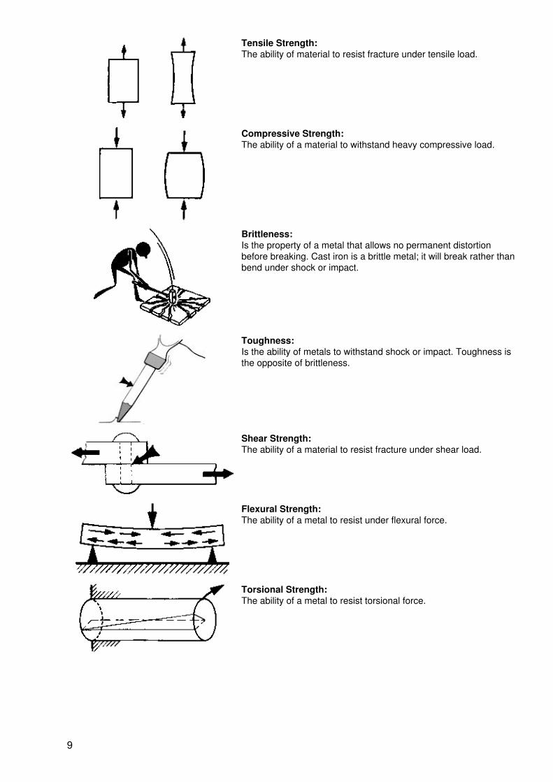
Tensile Strength:The ability of material to resist fracture under tensile load.
Compressive Strength:The ability of a material to withstand heavy compressive load.
Brittleness:Is the property of a metal that allows no permanent distortionbefore breaking. Cast iron is a brittle metal; it will break rather thanbend under shock or impact.
Toughness:Is the ability of metals to withstand shock or impact. Toughness isthe opposite of brittleness.
Shear Strength:The ability of a material to resist fracture under shear load.
Flexural Strength:The ability of a metal to resist under flexural force.
Torsional Strength:The ability of a metal to resist torsional force.
9

Collapsing Stress:The ability of a metal with a slim form to resist axial directed force.
Hardness:The ability of metal to withstand abrasion or penetration.
1.3.3 Manufacturing − Technological Properties:
Weldability:Means the ability to weld two metals together. The grade ofweldability depends on the content of carbon. Steels with a contentof max. 0.22% are more or less good weldable.
Machinability:Indicates how easy or difficult materials can be machined.
Malleability:Is the property of metals that allows it to be hammered or rolled intoother sides and shapes.
Castability:Is the property of metals that allows it to be molten and after it to becasted without any pores.
Hardenability:Is the property of iron metals that allows it to increase thehardening through structural transformations.
1.3.4 Chemical Properties:
10

Corrosion Resistance:Is the ability of a material to resist the attack of water, gases, acids orother chemicals.
1.4 Shapes and Sizes of Metal
Due to the wide variety of work performed in a metal shop and the necessity of conserving time, as well asreducing the amount of metal cut into steel chips, metals are manufactured in a wide variety of shapes andsizes.
There is a proper method for specifying the sizes and dimensions of metal when ordering:
Flat−bar: Thickness × Width × Length
Round−bar: Diameter × Length
Square−bar: Width × Length
Angle−bar: Thickness × Width × Length
Hexagon−bar: Diameter × Length (or Distance Across Flats ×Length)
Pipe: Diameter × Schedule × Length # 20 is thinnerthan # 40
Square−tubing: Thickness × Width × Length
Channel−Bar: Width × Height × Length
11
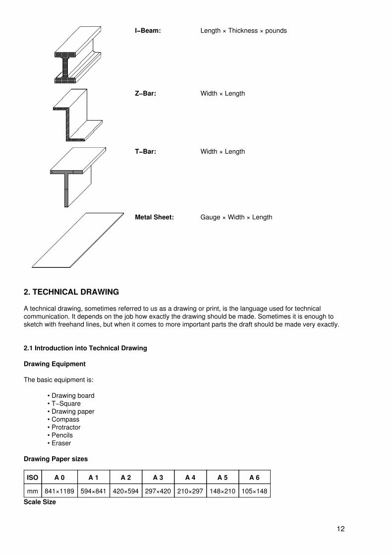
I−Beam: Length × Thickness × pounds
Z−Bar: Width × Length
T−Bar: Width × Length
Metal Sheet: Gauge × Width × Length
2. TECHNICAL DRAWING
A technical drawing, sometimes referred to us as a drawing or print, is the language used for technicalcommunication. It depends on the job how exactly the drawing should be made. Sometimes it is enough tosketch with freehand lines, but when it comes to more important parts the draft should be made very exactly.
2.1 Introduction into Technical Drawing
Drawing Equipment
The basic equipment is:
• Drawing board• T−Square• Drawing paper• Compass• Protractor• Pencils• Eraser
Drawing Paper sizes
ISO A 0 A 1 A 2 A 3 A 4 A 5 A 6
mm 841×1189 594×841 420×594 297×420 210×297 148×210 105×148
Scale Size
12

Scale is used to indicate the ratio of the drawing size to the actual size of the part. Scaling is often necessaryto enlarge small parts for clarity and to have room for dimensions and other details. Large objects are oftendrawn at a reduced scale in order to get the necessary information to fit a convenient size sheet of paper. Thescale is generally found in the title block of a drawing.
The dimensions shown on the drawing give the correct size of the part required. The actual drawing shouldnever be measured to determine that size to be machined.
2.2 Types of Lines
Various standard line styles and widths are used on technical drawings by the designer to precisely specifywhat is required. The examples below is the so called “alphabet of lines”:
Standard lines used for technical drawings:
Type Description Thicknessmm
Use
Free−handline
Thin black lines 0,25 to0,35
Sketches;break line
Object line Thick black lines 0,5 to 0,7 Indicate thevisible formor edges ofan object
Thin unbrokenline
Thin black line 0,25 to0,35
Shadingline, Threadline,Diagonalline
Hidden line Medium−weightblack lines (dash:approx. 4 mm,gap: 1 mm)
0,35 to 0,5 Indicatehiddencontours ofan object
Center line Thin lines withalternating longlines and shortdashes (dash:approx. 10 mm,gap: 1 mm)
0,5 to 0,7 Indicatecenters ofholes,cylindricalobjects, andothersections
Dimension line Thin black lineswith arrowhead ateach end.
0,25 to0,35
Indicatedimensionsof an object
13

Cutting−planeline
Thick black line(dash: approx. 7mm, gap: 1 mm)
0,5 to 0,7 Showimaginedsection
Cross−sectionline
Fine evenlyspaced parallellines at 45°. Linespacing is inproportion to thepart size
0,25 to0,35
Showsurfacesexposedwhen asection iscut
Exercise Sheet
Fill up the boxes with the given line type
2.3 Drawing Paper with title block
14

Exercise Sheet
1. Draw and dimension the object below using the given measurements. Use a piece of paper with atitle block.
2. Draw and dimension the object below using the given measurements. Use a piece of paper with atitle block.
15

2.4 Basic Rules
Dimensions are entered in millimeters without measures.
Dimension lines must have a distance of about 10 mm fromthe object edge and 7 mm from parallel dimension lines. Thedimensions should be placed above the dimension lines andshould be staggered.
Dimensions must be either read from below or from theright. For small dimensions the arrows are placed outside.
Symmetrical workpieces are dimensioned symmetrical to thecenter line which extends 2−3 mm beyond the object edge.
16

Simple workpieces are mostly drawn in front elevation only.If an elevation in which the area of a circle appears as astraight line is to be dimensioned, the diameter symbol is tobe placed in front of the dimension figure.
If the circle is shown in the elevation, then it is not necessaryto draw the diameter symbol.
The diameter is shown by two dimension arrows on thecircumference or drawn on the extension lines of the circle. Inthis cases no diameter symbol will be used.
A radius is symbolized by R and has only one dimensionarrow at the circumference. The center point is fixed by thecrossing of center lines.
Concealed edges are drawn as dash lines. The length ofeach dash depends on the size of the drawing.
Dash lines start and end with a dash at the object edges.
If visible and concealed edges coincide, the visible edges aredrawn.
17

Section views are used to show the interior form of an objectthat could not be shown clearly by conventional methods.The section areas are shaded, not the hollow spaces.
The smaller the section area the closer the shading lines.
In order to insert dimension figures the shading has to bebroken.
The shading lines are thin unbroken lines, which are angledat 45 degree to the center line or angled to the base edge.
Assembled workpieces are identified by opposite or variedshading. Section areas of one object are always shaded inthe same direction.
The outer diameter of a bolt thread is drawn as an objectline, the core diameter as a thin unbroken line. The distancebetween the thick and thin lines represents the threaddiameter.
Looking in direction of the shaft end the core diameterappears as a three−quarter circle in any position.
18

The ends of screws are normally 45 degree chamfered.
The core diameter of the internal thread is drawn as anobject line, the outer diameter as a thin unbroken line.
All lines of concealed thread are drawn as invisible edges.The thin three−quarter circle becomes a full circle shown inbroken line.
To be dimensioned are: Outer diameter (e.g. M 10 or UNC ¾)Useful length of thread Length of shaft with end, orrespectively depth of core hole without drill cone.
2.5 Drawing in three Elevations
Sometimes it is necessary to draft workpieces in three elevations to show all important parts of it.
19

3. METROLOGY
Over 90% of all countries in the world are presently using the Metric System. But there are still somecountries using the Inch System (e.g. United States, Canada, and England). With the reality of globalmanufacturing continually expanding, the need for metal workers in both systems of measurement willcontinue to grow.
3.1 Metric System
The metric system uses the meter and linear units based on the meter as its standards of measure. At theGeneral Conference on Weights and Measures in October, 1983, the meter, defined as the distance traveledby light in a vacuum during 1/299,792,458 of a second, was approved as a world standard.
20

All multiplies and subdivisions of the meter are directly related to the meter by a factor of ten. This makes iteasy to use the decimal system for calculations involving metric units.
Kilometer = km 1 km = 1,000 m
Meter = m 1 m = 10 dm = 100 cm = 1,000 mm
Decimeter = dm 1 dm = 10 cm = 100 mm
Centimeter = cm 1 cm = 10 mm
Millimeter = mm 1 mm = 1,000 mm
Micrometer = mm
3.1.1 Exercises − Metric System
Change into smaller units
1 m = 10 dm = 100 cm = 1,000mm
2.5 m dm = cm = mm
0.9 m = dm = cm = mm
1.2 m = dm = cm = mm
0.1 m = dm = cm = mm
Change into larger units
100 mm = 10 cm = 1 dm = 0.1 m
25 mm = cm = dm = m
120 mm = cm = dm = m
19 mm = cm = dm = m
386 mm = cm = dm = m
Summing Up
20 cm + 10 dm + 30 mm + 25 cm = 1,48 m
10 cm + 5 dm + 28 mm + 30.5 cm = mm
38 mm + 42 cm + 0.6 dm + 0.9 m = cm
5.5 dm + 122 mm + 44 cm + 1.2 m = dm
2.2 m + 86 cm + 77 cm + 333 mm = m
0.1 mm + 1.2 cm + 9.86 cm + 55.6 mm = mm
Mixed Operations
1 m + 37 mm − 5 dm + 40 cm = 937 cm
1.47 m − 37 mm − 1.8 dm + 36.5 cm = cm
96 mm − 3.8 cm + 1.36 m + 98 dm = dm
0.4 cm − 12 mm + 1.55 m − 8.4 dm = m
11 cm + 11 mm + 1.1 dm + 1.11 m = m
21
19.4 dm − 87.5 cm + 1.36 m − 94 mm = dm
Conversion from Metric to Inch or opposite
1 millimeter = 0.0394 inch 1 inch = 25.4millimeters
1 centimeter = 0.3937 inch 1 inch = 2.54centimeters
1 meter = 39.37 inches 1 foot = 0.3048meter
3.2 Inch System
Unlike the Metric System, within the Inch System there is no relationship of other linear units to the base inchunit. The values of yard, rod, mile, etc. have to be studied and kept in memory in order to use them. The inchcan be dived in halves (1/2), quarters (1/4), eighths (1/8), sixteenth (1/16), thirty−seconds (1/32), sixty−fourth(1/64), tenth, hundreds, thousandth, ten−thousands etc.
3.3 Metrology Introduction
Engineering metrology is defined as the measurement of dimensions: length, thickness, diameter, taper,angle, flatness, profiles and others.
An important aspect of metrology in manufacturing processes is dimensional tolerances. That is, thepermissible variation in the dimensions of a part. Tolerances are important not only for proper functioningsof products, they also have a major economic impact on manufacturing costs. The smaller we make thetolerances, the higher the production costs. These and related aspects of tolerances and tolerancing aredescribed later on in this course.
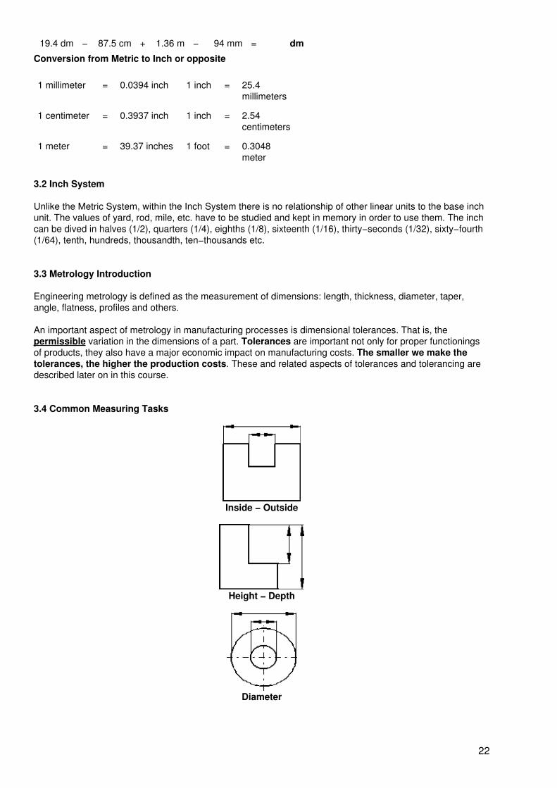
3.4 Common Measuring Tasks
Inside − Outside
Height − Depth
Diameter
22

Distance
Angle
Taper
Gear
Surface
Geometrical Form and Position
3.5 Measuring Equipment
A modern industrial fabrication could not function without precise measuring equipment. The parts producedare useless if they are not made to the exact sizes specified by the customer.
23

3.5.1 Care of Measurement Tools
Proper care of measuring tools and instruments is very important to maintain the accuracy and quality ofthese tools. Precision measuring tools and instruments are expensive and should be treated with care,otherwise their accuracy can be destroyed.
• Never drop a measuring tool.• Keep measuring tools away from chips, welding and grinding sparks.• Never place measuring tools on oily or dirty surfaces.• Store measuring tools in separate boxes to avoid scratches, nicks, or dents.• Clean the tools and apply a light film of oil on the handling surfaces before putting themaway.
3.5.2 Sample of Gauges
Outside Radius Gauge
Inside Radius Gauge
Angle Form Gauge
Limit Snap Gauge
24

Thread Gauge
Angle Form Gauge
Limit Plug Gauge
Outside Thread−Ring Gauge
Inside Thread−Plug Gauge
3.5.3 Indirect Reading Instruments
Inside and Outside Calipers are comparison tools used to make approximate measurements of the outsidediameter of round workpieces. The caliper cannot be read directly and its setting must be checked with a ruleor a vernier caliper.
25

Inside caliper with curved legs, a spring, and an adjusting nut
Outside caliper with curved legs, a spring, and an adjusting nut
3.5.4 Angle Measuring Instruments
With a simple Protractor the measuring arm can be set against a circular degree scale from 0 degree to 180degree. The measuring error is around 1 degree.
With a more precise Universal Bevel Protractor angular measurements can be carried out with an accuracy of5 minutes.
Simple Protractor
Universal Bevel Protractor
26

3.5.5 Comparative Length−Measuring Instruments
These instruments compare dimensions, hence the word comparative.
Dial Caliper
Digital Caliper
Digital Micrometer
27

Dial Gauge
3.5.6 Direct Reading Instruments
Steel Rules
Steel rules are the most common linear measuring tools and are available in the metric or inch system. Metricrules are graduated in both millimeters and half−millimeters. Some rules are available with both inch andmillimeter graduation.
28

Exercise Sheet − Measuring with the Steel Rule
Measure all given shapes in metric and inch
Vernier Calipers
Vernier calipers are precision measuring instruments used to make internal, external and depthmeasurements. Both systems metric and inch are available, and some styles of vernier caliper provide metricreadings on one side and inch readings on the other side.
The common size of verniers for machine shops are 200 mm, 250 mm and 300 mm. The precision dependson the vernier scale. Common types provide an accuracy of either 0.05 mm or 0.02 mm. The example belowshows an accuracy of 0.05 mm.
How to read a Metric Vernier Caliper (accuracy 0.05 mm):
29
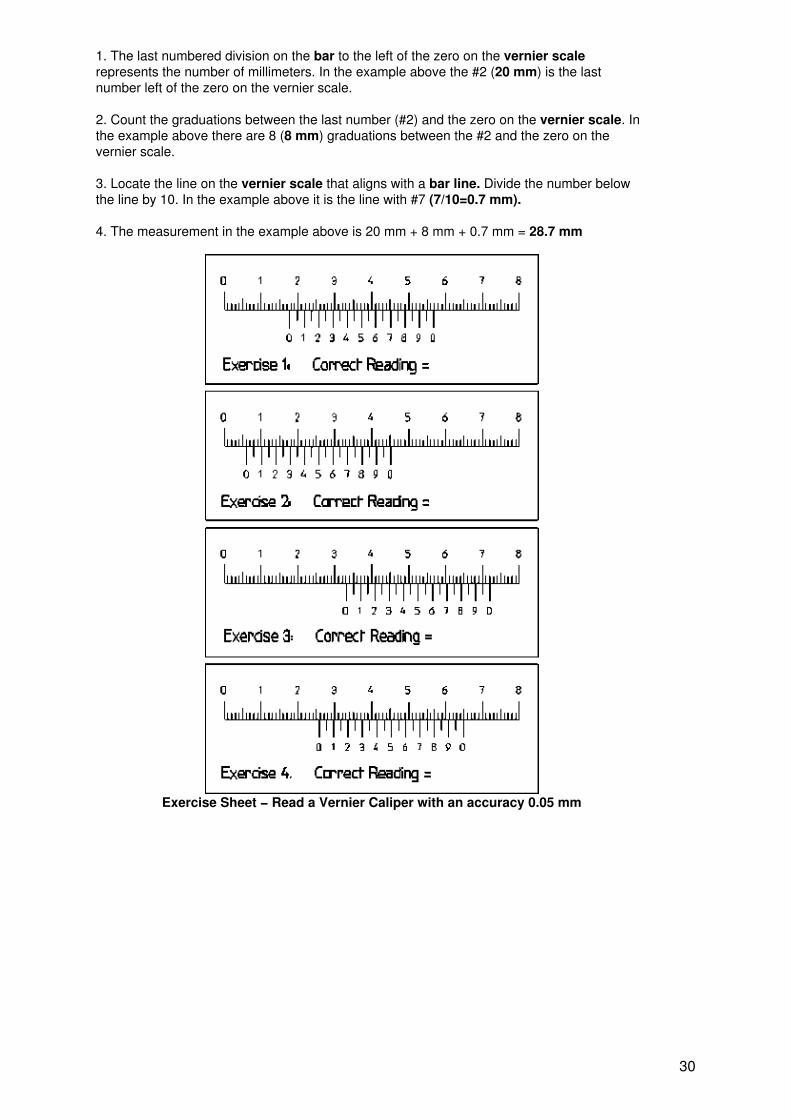
1. The last numbered division on the bar to the left of the zero on the vernier scalerepresents the number of millimeters. In the example above the #2 (20 mm) is the lastnumber left of the zero on the vernier scale.
2. Count the graduations between the last number (#2) and the zero on the vernier scale. Inthe example above there are 8 (8 mm) graduations between the #2 and the zero on thevernier scale.
3. Locate the line on the vernier scale that aligns with a bar line. Divide the number belowthe line by 10. In the example above it is the line with #7 (7/10=0.7 mm).
4. The measurement in the example above is 20 mm + 8 mm + 0.7 mm = 28.7 mm
Exercise Sheet − Read a Vernier Caliper with an accuracy 0.05 mm
30

Exercise Sheet − Read a Vernier Caliper with an accuracy 0.02 mm
Hands On − Measurement Exercise
Steel Ruler Vernier Caliper
No. mm inch No. mm inch
1 1
2 2
3 3
4 4
5 5
6 6
7 7
8 8
9 9
10 10
11 11
12 12
31

13 13
14 14
15 15
16 16
17 17
Hands On − Measurement Exercise
Steel Ruler Vernier Caliper
No. mm inch No. mm inch
1 1
2 2
3 3
4 4
5 5
6 6
7 7
8 8
9 9
10 10
11 11
32

4. FITS AND ISO TOLERANCES
Limits and Fits
In the world of manufacturing it is almost impossible to reach exactly the given dimension for a workpiece.Therefore the off−sizes must be tolerated. To make sure, that all mating parts will fit each other they shouldbe fabricated within certain limits of nominal dimension.
Common Expressions in the world of manufacturing:
Nominal The given size in the technical drawing N
Upper Limit The maximum allowed size. UL
Lower Limit The minimum allowed size. LL
Upper Tolerance Is the difference between Nominal and Upper Limit UT
Lower Tolerance Is the difference between Nominal and the Lower Limit LT
Tolerance Is the difference between the Limits T
Shaft with anominaldimensionof 20 mm
33

Shaft withtoleranceddimension,2 mm plusand 2 mmminus isallowed.
UL = N +UTLL = N− LTT = LT + UT
Limits − Exercise Sheet
NominalDimension
UpperLimit
(max. Æ)
LowerLimit
(min. Æ)
UpperTolerance
LowerTolerance
Tolerance
20.00 mm 20.00 mm 20.00 mm 0.00 mm 0.00 mm 0.00 mm
20.00 mm 20.50 mm 20.00 mm 0.50 mm 0.00 mm 0.50 mm
20.00 mm 20.25 mm 19.75 mm 0.25 mm 0.25 mm 0.50 mm
20.00 mm 20.00 mm 19.80 mm 0.00 mm 0.20 mm 0.20 mm
20.00 mm 20.15 mm 19.95 mm 0.15 mm 0.05 mm 0.20 mm
20.00 mm 20.00 mm 19.95 mm 0.00 mm 0.05 mm 0.05 mm
20.00 mm 20.02 mm 19.99 mm 0.02 mm 0.01 mm 0.03 mm
20.00 mm 20.01 mm 19.99 mm 0.01 mm 0.01 mm 0.02 mm
34

20.00 mm 20.035mm
20.00 mm 0.035 mm 0.00 mm 0.035 mm
20.00 mm 20.055mm
20.045mm
0.055 mm 0.045 mm 0.010 mm
Classes of Fits
Force Fit (Interference Fit)
Transition Fit
35

Loose Fit (Clearance Fit)
5. LAYING OUT
Laying out is the operation of scribing center locations, straight lines, arcs, circles, or contour lines on thesurface of a piece of metal to show the machinist the finished size and shape of the part to be manufactured.The information regarding the size and shape of part is taken from a technical drawing. The care andaccuracy of the layout plays an important role in determining the accuracy of finished parts, since themachinist uses these layout lines as a guide for machining.
5.1 Layout Tools and Accessories
Tools &Accessories
Details
Surface Plate orMarking Table
Is a plate or a table made of cast iron or of granite. It must be adjusted absolutehorizontally. Its surface must be perfect plane to ensure accurate scribing. To bringworkpieces to the correct position on the marking table there are some other deviceslike prism, angle plate, V−Blocks and Parallels.
Steel Rule Steel rules are the most common linear measuring tools and are available in themetric or inch system. Metric rules are graduated in both millimeters andhalf−millimeters. Some rules are available with both inch and millimeter graduation.
Scriber A scriber is a layout tool used for drawing layout lines on a workpiece. They aremade of tool steel with hardened and tempered points. It is important that the point ofthe scriber be as sharp as possible to produce clear, thin, layout lines.
Center Punch Normally ground to an angle of 90 degree. Before drilling a hole the center must bepunched. To make a line more visible for cutting or oxy−acetylene cutting it is helpfulto punch the line.
Solid Square orTry−Square
Is used for laying out workpiece in combination with steel rule and scriber. It is alsoused to check the angles and the surfaces for flatness.
Divider The divider is used to transfer length or circles to the workpiece. Dividers areavailable with and without fixing devices.
Protractor A simple protractor has a measuring range from 0 to 180 degree. The measuringerror is around 1 degree.
Surface Gauge orVernier HeightGauge
Is normally used in combination with a surface plate and an angle plate to markparallel lines. Using the simple type, the height can be adjusted with a steel rule.
36

Angle Plate An angle plate is a precision L−shaped tool usually made of hardened steel. All itssurfaces are ground to an accurate 90−degree angle and are square and parallel. Itis used to support workpieces on a 90−degree angle during the layout process.
V−Blocks or Prism It is an accurate fabricated layout device to hold cylindrical workpieces during thelayout process. They have one or more accurate 90−degree V−slots.
5.2 Layout Procedure
5.2.1 Laying out with Try−Square and Steel Rule
1. Remove all burrs from the workpiece and clean it properly.2. Start the layout from a square machined (or filed) surface.3. Use a try−square and a steel rule.4. Place the point of the sriber on the workpiece against the try−Square edge. Hold thescriber 15 degree inclined away from the workpiece and in the direction in which it is to bedrawn.
37

5.2.2 Laying Out Circles with the Divider
1. Lay out the center of the circle2. Punch the center of the circle3. Adjust the divider to the proper radius while using a steel rule or a vernier caliber4. Place one point of the divider in the center punch hole and give some force to this leg.5. Move around the fixed leg and scratch the surface.
Laying out circles
Laying out parallel lines
5.2.3 Laying Out with Surface Gauge
38

5.2.4 Laying Out with Protractor
5.2.5 Center Punch Procedure
1. Make sure that the point of the punch is sharp before starting.2. Hold the punch at a 45 degree angle and place the point carefully on the layout line.3. Tilt the punch to a vertical position and strike it gently with a light hammer.4. If the punch mark is not in the proper position, correct it as necessary.
6. BENCH WORK TOOLS
Even in the time of CNC technology it is important to know how to do bench work using different hand tools,because still today bench work plays a big rule in machine maintenance or in metal fabrication.
39

This chapter will provide the trainee with the necessary knowledge about bench work. This includes the basictools as well as their proper use.
6.1 Work Bench
• The workbench should be sturdy and when possible fixed with the shop floor.• It is advisable to use wood for the bench board.• The height of the workbench should depend on the height of the craftsman.• Keep the workbench clean. Put only the tools necessary for the work on it.• Measuring tools should be all the time separated from the other tools. Place them accuratelyon the wooden tray board.
6.2 Bench Vise
• The base of a bench vise is normally made of cast iron. The jaws are hardened. Clampingsoft workpieces requires covering the jaws with an aluminum sheet cover.
• The size of the bench vise is measured by the width of the jaws and the maximum openingbetween the jaws.
• There are different types of bench vises available: With or without an anvil plate, with a pipeclamping device, machine vise for drill press, and adjustable in any position within 360degree.
40

6.3 Hand Hacksaw
A hand hacksaw mainly serves to separate materials and also to produce grooves and slits.
By moving the saw in the direction of cut (cutting motion) with simultaneous pressure on the saw (cuttingpressure), the teeth penetrate into the material and remove chips.
There are different hacksaw blades, depending on the metal to be cut, available:
Coarse: for soft materials appr. 14 teeth per inch.
Medium: for normal material appr. 22 teeth per inch.
Fine: for hard material appr. 32 teeth per inch.
In order to achieve a perfect cut, file with a triangular file a small notch beside the marking line to get a goodstart, then place the saw with an angle of tilt (as shown in the picture below) and start with sawing.
41

Forward stroke with pressure. Return stroke without pressure. Use the full length of the saw blade.
Saw in a straight line along the marking line.
Work safety:
When sawing through reduce pressure on hand hacksaw just before the workpiece separate.
6.4 Chisel Tools
In chiseling the cutting edge of a chisel is driven into a workpiece by impact. A chisel must be harder than thepiece being worked. Most chisels are made of alloyed tool steels.
Flat Chisel
Wedge angle for soft materials 30 to 50 degree; for mild steel 60 to 70 degree; for alloyed steels 70 to 80degree
Work Process:
• The workpiece must be properly clamped when chiseling.
• The chisel must be struck on the center of the head, in the direction of the axis of the chisel.
• The correct wedge angle must be maintained when grinding the chisel (measure with anangle gauge). The tool must be cooled frequently when sharpening, so that it does not lose itstemper.
42

Shearing with a shearing chisel
The head of the chisel must be free of burrs and grease
6.5 Files
The file is a cutting tool to work materials. It has many cutting edges which are like small chisels (file teeth)and are harder than the material being worked upon. For cutting metals normally Cross−Cut files are used.These files have an overcut, and an upcut. When using a file, several cutting wedges always act at the sametime.
• To file different materials there are various coarses available, such as smooth−cut,second−cut, and bastard cut.
43

• The length of the file body normally used is between 100 mm and 350 mm.
• The file handle is either from wood or from plastic.
Types of Files
1. Square File large
2. Flat File
3. Square File small
4. Triangle File
5. Round File
44

6. Half−Round File
7. Knife File
8. Flat−Triangle File
45

File Handling
• Clamp the workpiece as close as possible to the jaws of the vise. Use protective jaws(Aluminum) to protect the workpiece.
• Start with a rough file for removing more material then take a smooth file to reach a goodsurface.
• Forward stroke with pressure; Return stroke without pressure.
• Move with the file crosswise to control the area of filing.
• Clean the file from time to time (especially smooth files) with a wire brush to prevent messyfinishes.
• Never work with a file without a file grip.
• Make sure that the file grip is properly attached, that it has the right dimension and that it isnot splitted.
6.6 Hammer
• A hammer is used nearly in every operation related to metal works.
• They are made of cast steel or carbon steel.
• It mainly consists of a face, peen and body. The face and the peen are hardened andtempered but the rest of the body is kept soft. A wooden handle is fitted in the eyehole of thehammer with the help of a wedge. The wedge spreads the handle and fixes it inside the hole.
• Hammers are made in the size range of 25 Gram to 10 Kg.
• There are different types of hammer available:
Fitters hammer, Ball pane hammer, Rubber mallet, Plastic hammer, Woodhammer, Sledge hammer, Claw hammer, Aluminum hammer, copper etc.,
46
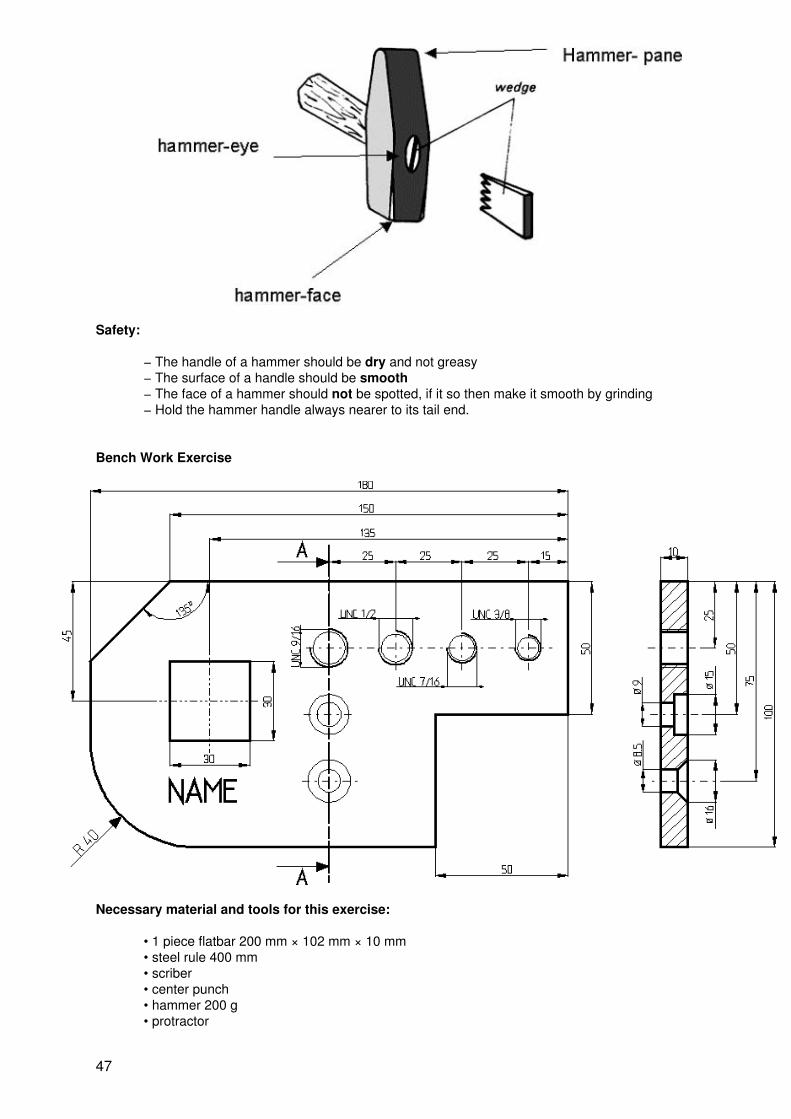
Safety:
− The handle of a hammer should be dry and not greasy− The surface of a handle should be smooth− The face of a hammer should not be spotted, if it so then make it smooth by grinding− Hold the hammer handle always nearer to its tail end.
Bench Work Exercise
Necessary material and tools for this exercise:
• 1 piece flatbar 200 mm × 102 mm × 10 mm• steel rule 400 mm• scriber• center punch• hammer 200 g• protractor
47

• try square• combination square• vernier caliber 250 mm• depth vernier caliber• hand hacksaw• flat file 250 mm rough and bastard• triangular file 250 mm rough and bastard• different twist drills• different screw taps• different countersink• letter stamps• chisel
Metal Plate − Working Step No. 1
1. Take a piece of flat bar with a measurement of 200 mm lengths and 105 mm width and 10mm thickness.
2. Take the letter “A” stamp and stamp it as shown in the above drawing.
3. File surface of edge A even and remove all rust and forging scale. First use a rough file,then for finishing the surface a bastard file. Control the evenness with the try square.
4. Layout lines from the left side as well as on the right side. Use edge A as a reference to putthe try square and scribe the lines.
5. Center punch the lines with at least 5 mm distance between the marking points.
6. Cut on the outer part of the lines using the hand hacksaw and leave at least 1mmallowance for filing.
7. File the surfaces of edges B and D in a right angle to surface A. File the 1mm excess tothe size required.
8. File surface of edge C even and parallel to edge A to the size required. First use a roughfile, then for finishing the surface a bastard file.
Metal Plate − Working Step No. 2
48

1. Take a combination square and set 135 degrees angle using a protractor.
2. Put the combination square at edge A.
3. Scribe a line with the scriber.
4. Center punch the line with at least 5 mm distance between the marking points.
5. Cut on the outer part of the line using the hand hacksaw and leave at least 1mm allowancefor filing.
6. File the surface of edge B in an angle of 135 ° to surface A. File the 1mm excess to thesize required.
Metal Plate − Working Step No. 3
1. Take divider and steel rule for laying out the central point of radius = 40 mm.
49
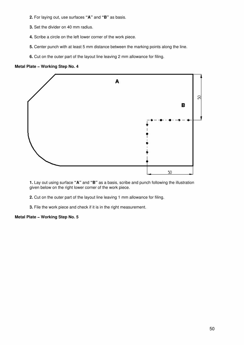
2. For laying out, use surfaces “A” and “B” as basis.
3. Set the divider on 40 mm radius.
4. Scribe a circle on the left lower corner of the work piece.
5. Center punch with at least 5 mm distance between the marking points along the line.
6. Cut on the outer part of the layout line leaving 2 mm allowance for filing.
Metal Plate − Working Step No. 4
1. Lay out using surface “A” and “B” as a basis, scribe and punch following the illustrationgiven below on the right lower corner of the work piece.
2. Cut on the outer part of the layout line leaving 1 mm allowance for filing.
3. File the work piece and check if it is in the right measurement.
Metal Plate − Working Step No. 5
50

1. Lay out the two squares which are 30 mm × 30 mm and 20 mm × 20 mm as shown in thedrawing above using surface “A” and “B” as a basis.
2. Mark the squares exactly as shown in the drawing above.
3. Centerpunch the lines as shown in the drawing above.
4. Drill the punch mark of the inner square with a 8.5 mm twist drill.
Metal Plate − Working Step No. 6
1. Cut the bridge between the wholes using chisel and hammer.
2. File the outer square 30 mm × 30 mm using the necessary files.
3. Check if the filed square is parallel to surfaces “A”, “B”, “C” and “D”.
Metal Plate − Working Step No. 7
51

1. Mark a border line for the height of the letters and vertical line for each letter. For the widthlet approximately 1 mm clearance both sides.
2. Adjust the letter stamp on the surface of the work piece.
3. Strike the letter stamp using a 200 g hammer.
Metal Plate − Working Step No. 8
1. Lay out the lines for drilling using the measurement given.
2. Punch all the mark for drilling.
Metal Plate − Working Step No. 9
52

1. Drill the holes with required twist drills.
2. Countersink both sides of holes with countersink tool.
3. Tap the threads with required screw taps.
4. Check the specifications for holes “1” and “2” in the complete technical drawing of theworkpiece.
Bench Work Exercise − New
53

Necessary material and tools for this exercise:
• 1 piece flatbar 100 mm × 100 mm × 10 mm• steel rule 400 mm• scriber• center punch• hammer 200 g• protractor• try square• combination square• vernier caliber 250 mm• depth vernier caliber• hand hacksaw• flat file 250 mm smooth and rough• triangular file 250 mm smooth and rough• square file 250 mm smooth and rough• different twist drills• different screw taps• different countersink• letter stamps• chisel
Metal Plate − Working Step No. 1
54

1. Take a piece of flat bar with a measurement of 100 mm lengths and 100 mm width and 10mm thickness.
2. The fianl dimension of the workpiece should be 95 mm × 90 mm × 10 mm with atolerance of plus 0.2 mm and minus 0.2 mm.
3. Take the letter “A” stamp and stamp it as shown in the above drawing.
4. File surface of side A even and remove all rust and forging scale. First use a rough file,then for finishing the surface a smooth file. Control the evenness with the try square.
5. Layout lines from the left side as well as on the right side. Use side A as a reference to putthe try square and scribe the lines.
6. Center punch the lines with at least 5 mm distance between the marking points.
7. Cut on the outer part of the lines using the hand hacksaw and leave at least 1mmallowance for filing.
8. File the surfaces of sides B and D in a 90 degree angle to surface A. File the 1mm excessto the size required.
9. File surface of edge C even and parallel to side A to the size required. First use a roughfile, then for finishing the surface a smooth file.
Metal Plate − Working Step No. 2
55

1. Take a combination square and set 135 degrees angle using a protractor.
2. Put the combination square at side A.
3. Scribe a line with the scriber.
4. Center punch the line with at least 5 mm distance between the marking points.
5. Cut on the outer part of the line using the hand hacksaw and leave at least 1mm allowancefor filing.
6. File the surface in an angle of 135 ° to surface A. File the 1mm excess to the sizerequired.
Metal Plate − Working Step No. 3
56

1. Take divider and steel rule for laying out the central point of radius = 40 mm.
2. To layout, use surfaces “A” and “D” as basis.
3. Set the divider on 40 mm radius.
4. Scribe a circle on the left lower corner of the work piece.
5. Center punch with at least 5 mm distance between the marking−points along the line.
6. Cut on the outer part of the layout line leaving 2 mm allowance for filing.
7. File the surface exactly following the marks.
Metal Plate − Working Step No. 4
1. Lay out the two squares which are 30 mm × 30 mm and 20 mm × 20 mm as shown in thedrawing above using surface “A” and “B” as your basis.
2. Mark the squares exactly as shown in the drawing above.
3. Centerpunch the lines as shown in the drawing above.
4. Drill the punch mark of the inner square with 8.5 mm twist drill.
Metal Plate − Working Step No. 5
57

1. Cut the bridge between the wholes using chisel and hammer.2. File the outer square 30 mm × 30 mm using the necessary files.3. Check if the filed square is parallel to surfaces “A”, “B”, “C” and “D”.
Metal Plate − Working Step No. 6
1. Mark two lines for the height of the letters and vertical lines for each letter. For the width letapproximately 1 mm clearance both sides.
2. Adjust the letter stamp on the surface of the work piece.
3. Strike the letter stamp using a 200 g hammer.
Metal Plate − Working Step No. 7
58

1. Lay out the lines for drilling using the measurement given.2. Punch all the marks for drilling.
Metal Plate − Working Step No. 9
1. Drill the holes with required twist drills.2. Countersink both sides of holes with countersink tool.3. Tap the threads with required screw taps.4. Check the specifications for holes “1” and “2” in the complete technical drawing of theworkpiece.
59

7. PRINCIPLES OF MECHANICAL METAL CUTTING
A large portion of manufacturing operations in the world consists of machining metal to size and shape. Tobe competitive, it is important that machining operations be as cost−efficient as possible. This requires a goodknowledge of metals, cutting tools, and machining conditions and processes.
7.1 Classification of Metal Cutting Processes
Hand Cutting Processes Machine Cutting Processes
• Filing• Chiseling• Hand Hacksawing• Shearing• Hand Tapping• Die−Tapping• Hand Reaming
• Drilling• Hacksawing• Turning• Milling• Grinding• Shaping• Machine Threading• Machine Reaming
Chiseling
Sawing
Turning
Grinding
7.2 Angles of tools
• What is common to all cutting tools is the wedge shape BETA (?).
• To cut metals, the tool must be wedge−shaped, be resistant to abrasion and tenacious.
60

• For different cutting operations there is a need for different tool angles.
• Cutting tools with small wedge angles penetrate the material more easily but also tend tobreak off more easily if the material is hard
Wedge Angle Beta (?):
The wedge angle must suit to the material being worked.
• The smaller the wedge angle is, the lower the expenditure of force.• The harder the material, the larger the wedge angle should be chosen.
Clearance Angle Alpha (?):
The clearance angle is the angle between the flank of the tool and the surface being cut.
Friction and heating depend upon this angle. The angle should be chosen as such that the tool could cutfreely.
• Soft materials require a larger clearance angle because they generate more heat andfriction.
Rake Angle Gamma (?):
The rake angle is the angle between the cutting face and the plane of reference of the tool, an imaginarysurface perpendicular to the cut surface.
The rake angle influences the chip formation.
• Large angle: good chip flow, low cutting force• Small to negative angle: great cutting force, highly robust cutters
61

7.3 Cutting Tool Guideline
• Cutting tools are expensive therefore take care of them.
• Always use sharp cutting tools to ensure an efficient cutting action and accurate work.
• Use the largest nose radius possible (Cold chisel, lathe tool….)
• Clamp the workpiece as short as possible and securely.
• Always use the speeds, feeds, and depth of cuts recommended by the manufacturer for thematerial being cut and the cutting tool used.
• Use enough of the proper coolant for the material being cut and the cutting tool used.
8. DRILLING
8.1 Drill Press
A drill press is a machine used for drilling operations available in a wide variety of types and sizes to suitdifferent types and sizes of workpieces. The most common machine type found in a metal shop is thefloor−type drill press.
8.1.1 Drill Press Parts
Although drill presses are manufactured in a wide variety of sizes, all drilling machines contain certain basicparts.
Base:
The base, usually made of cast iron, provides stability for the machine and rigid mounting for the column. Thebase is usually provided with holes so that it may be bolted to a table or bench to keep it rigid. The slots orribs in the base allow the work−holding device for the workpiece to be clamped to the base.
Column:
The column is an accurate, vertical, cylindrical post that fits into the base. The table, which is fitted on thecolumn, may be adjusted to any point between the base and head. The head of the drill press is mountednear the top of the column.
Table:
The table, either round or rectangular in shape, is used to support the workpiece to be machined. The table,whose surface is at 90 degree to the column, may be raised, lowered, and swiveled around the column. Onsome models it is possible to tilt and lock the table in either direction for drilling holes on an angle. Slots areprovided in most tables to allow jigs, fixtures, or large workpieces to be clamped directly to the table.
Drilling Head:
The head, mounted close to the top of the column, contains the mechanism to revolve the cutting tool andadvance into the workpiece. The spindle, which is a round shaft that holds and drives the cutting tool, ishoused in the spindle sleeve. The spindle sleeve does not resolve, but is moved up and down by the handfeed lever that is connected to the pinion on the rack of the spindle sleeve. The end of the spindle may have atapered hole to hold taper shank tools, or it may be threaded or tapered for attaching a drill chuck.
The hand feed lever is used to control the vertical movement of the spindle sleeve and the cutting tool. Adepth stop, attached to the spindle sleeve, can be set to control the depth that a cutting tool enters theworkpiece.
62

Drill Chuck:
Drill chucks are the most common devices used on a drill press for holding straight−shank cutting tools. Mostdrill chucks contain three jaws that move all at the time when the outer collar is turned. The three jaws holdthe straight shank of a cutting tool securely and cause it to run accurately.
8.1.2 Drill Sleeves and Sockets:
The size of the tapered hole in the drill press spindle is generally in proportion to the size of the machine: Thelarger the machine, the larger the spindle hole. A drill sleeve is used to adapt the cutting tool shank to themachine spindle if the taper on the cutting tool is smaller than the tapered hole in the spindle.
Before a taper shank tool is mounted in a drill press spindle, be sure that the external taper of the tool shankand the internal taper of the spindle are thoroughly cleaned. Align the tang of the tool with the slot in thespindle hole and, with a sharp upward snap, force the tool into the spindle.
63

Remove a taper shank tool:
A drift, a wedge−shaped tool, is used to remove a taper−shank tool from the drill press spindle. Place a pieceof wood under the tool. Insert the drift and sharply strike the end of it with hammer to remove the tool from thedrill press spindle.
8.2 Twist drill
A twist drill is a cutting−tool used to produce a hole in a piece of metal or other material. The most commondrill manufactured has two cutting edges (lips) and two straight or helical flutes.
The flutes provide the cutting edges with cutting fluid and allow the chips to escape during the drillingoperation.
Drill bit materials:
High−speed steels drills are the most commonly used drills, since they can be operated at good speeds andthe cutting edges can withstand heat and wear.
Cemented−carbide drills, which can be operated much faster than high−speed steel drills, are used to drillhard materials. They can be operated at high speeds and they can withstand higher heat.
64

8.2.1 Twist drill parts and cutting angles
A twist drill may be divided into three main sections:
• Shank: The shank is the part of the drill that fits into a holding device. It may be either straightor tapered.
• Body: The body contains the flutes, margin, and body clearance of the drill.
• Point: Shape and condition of the point are very important to the cutting action of the drill.
Angles for General Purpose
Angles for Soft Material
65

Angles for Hard Material
Cutting angles of a twist drill
The parts of a twist drill point
8.2.2 Drill Sizes
Metric drills:
Metric drills are available in various set ranges.
Miniature set: Sizes from 0.04 to 0.99 mm in steps of 0.01 mm
Straight shank: Sizes from 0.5 to 20 mm in steps of 0.02 to 1 mm (depending on the size)
Taper shank: Sizes from 8 to approx. 100 mm
Inch drills:
The most common system for inch drills is the fractional system.
Drills are available in sizes from 1/64 to 3 ½ in. in diameter, varying in steps of 1/64 in. from one size to thenext. Drills larger than 3 ½ in. in diameter must be ordered specially from the manufacturer.
66

8.2.3 Setting the Spindle Speed
To find the right number of revolutions per minute at which a drill press spindle will be set, the followinginformation must be known:
• The recommended cutting speed (CS) of the material to be drilled• The type of drill bit, most likely HSS• The diameter of the drill
Other important factors might affect the setting of the spindle speed:
• The type and the condition of the machine• The accuracy and finish of the hole required• The rigidity of work setup• The use of cutting fluid
Calculating the spindle speed for Metric drills:
CS = cutting speed of the material in meter per minute
D = diameter of the drill in mm
? = 3.1416
r/min = revolution per minute
Example:
Calculate the r/min. at which a drill press should be set to drill 12 mm hole in a piece of mild steel.
r/min = (CS × 1000) / (3,1416 × 12)
r/min = 30000 / 37.69
r/min = 796
Cutting speed for high−speed steel (HSS) drills
Material Stainless Steel Tool Steel Cast Steel Mild Steel Aluminum & Brass
Cutting Speed (CS) 10 M/Min 15 M/Min 20 M/Min 30 M/Min 60 M/Min
Drill bit Ø in mm Revolution per Minute (rpm/min)
2 1592 2387 3183 4775 9549
3 1061 1592 2122 3183 6366
4 796 1194 1592 2387 4775
67

5 637 955 1273 1910 3820
6 531 796 1061 1592 3183
7 455 682 909 1364 2728
8 398 597 796 1194 2387
9 354 531 707 1061 2122
10 318 477 637 955 1910
11 289 434 579 868 1736
12 265 398 531 796 1592
13 245 367 490 735 1469
14 227 341 455 682 1364
15 212 318 424 637 1273
20 159 239 318 477 955
25 127 191 255 382 764
Exercise Sheet − Calculating the spindle speed of Metric drills
CS = cutting speed of the material in meter per minute
D = diameter of the drill in mm
? = 3.1416
r/min = revolution per minute
Exercise 1:
Calculate the r/min. at which a drill press should be set to drill a 10 mm hole in a piece of aluminum.
Exercise 2:
Calculate the r/min. at which a drill press should be set to drill a 22.5 mm hole in a piece of mild steel.
Exercise 3:
Calculate the r/min. at which a drill press should be set to drill a 5.8 mm hole in a piece of mild steel.
8.3 Different Drill Press Operations
68

Countersink Tool
Counterbore Tool
8.4 Facts and Problems
The most common drill problems encountered are illustrated below.
69

Excessive speed will causewear at outer corners of drill.This leads to more regrindingof material.
Excessive feed sets upabnormal end thrust thatcauses breakdown of chiselpoint and cutting lips. Failureincluded by this cause will bebroken or split drill.
Cutting with unequal angleswill cause one cutting edge towork harder than the other.This causes to poor tool life.
Cutting lips unequal in lengthcause chisel point to be offcenter with axis and will drillholes oversize by appr. Twicethe amount of eccentricity.
8.5 Drill Press Safety
Safety Rules
• Never wear loose clothing around machinery
• A hair net or a cap must protect long hair to prevent it from becoming caught in therevolving parts of the drill press.
• Never wear rings, watches, bracelets or necklaces while working in a machine shop.
• Always wear safety glasses when operating any machine.
• Never set the speed, adjust or measure the work until the machine is completely stopped.
• Keep the work area and floor clean and free of oil and grease.
• Never clamp taper shank drills, end mills, or non−standard tools in a drill chuck.
• Never leave a chuck key in a drill chuck at any time.
• Always use the brush to remove chips.
• Always clamp workpieces when drilling holes larger than ½ in. (12.7 mm) in diameter.
70

• When drilling sheet metal, it is necessary to clamp the sheet on a piece of wood.
• Reduce drilling pressure as the drill breaks through the workpiece.
• Always remove the burrs from a hole that has been drilled.
9. CUTTING THREADS WITH TAP & DIES
Whenever possible, threads should be cut with machines where they can be accurately controlled and thethread cut will be of high quality. Sometimes it may be necessary, due to the size and shape of the workpiece,or because only a few parts are required, to cut the thread with hand tools. Done with care, fairly accurateinternal threads can be cut with a tap; external threads can be cut with a die.
9.1 Main Parts of a Screw Thread
9.2 Hand Tapping
Hand Tap
A tap is a cutting tool used to cut internal threads. Normally its made of high−speed steel (HSS).
Hand taps are usually made in sets of three, because it is better to distribute all the cutting work during thethread−process to three taps.
No. 1 (taper) tap: 1 ring onshank
No. 2 (plug) tap: 2 rings onshank
No. 3 (bottoming) tap: without ring
The most common taps have two or three flutes in order to form the cutting edges, transport the chips out ofthe hole and give way for the lubricant. The end of the tap is square so that a tap wrench can be used to turnit into a hole.
71

Tap − Cutting Angles
Tap Wrenches Adjustable
Tap Wrenches Fixed
Tapping a Hole
Before a tap is used, a hole must be drilled in the workpiece to the correct tap drill size. The tap drill size(T.D.S.) is the size of the drill that should be used to leave the proper amount of material in the hole for a tapto cut threads. Then countersink both sides of the hole.
If there is no tap drill size chart available, the tap drill size can be easily found by applying simple formulas:
Inch ThreadsT.D.S. = D in inch − 1/N
Metric ThreadsT.D.S. = D in mm − P
72
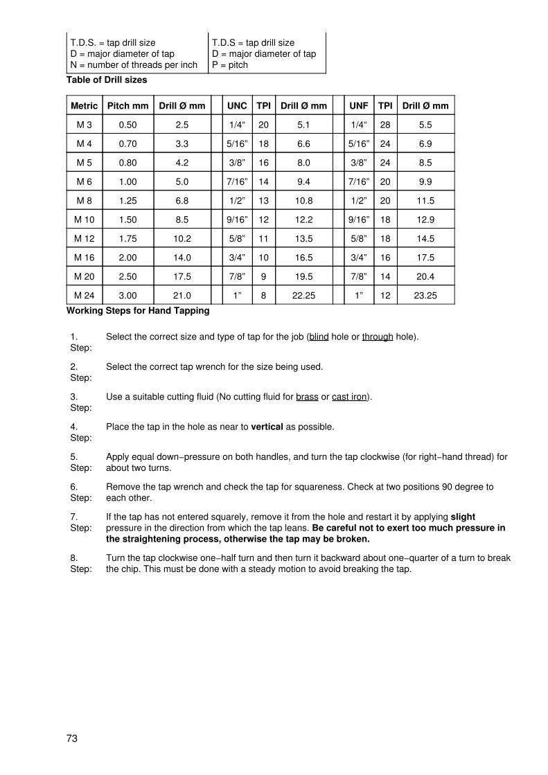
T.D.S. = tap drill sizeD = major diameter of tapN = number of threads per inch
T.D.S = tap drill sizeD = major diameter of tapP = pitch
Table of Drill sizes
Metric Pitch mm Drill Ø mm UNC TPI Drill Ø mm UNF TPI Drill Ø mm
M 3 0.50 2.5 1/4“ 20 5.1 1/4“ 28 5.5
M 4 0.70 3.3 5/16” 18 6.6 5/16” 24 6.9
M 5 0.80 4.2 3/8” 16 8.0 3/8” 24 8.5
M 6 1.00 5.0 7/16” 14 9.4 7/16” 20 9.9
M 8 1.25 6.8 1/2” 13 10.8 1/2” 20 11.5
M 10 1.50 8.5 9/16” 12 12.2 9/16” 18 12.9
M 12 1.75 10.2 5/8” 11 13.5 5/8” 18 14.5
M 16 2.00 14.0 3/4” 10 16.5 3/4” 16 17.5
M 20 2.50 17.5 7/8” 9 19.5 7/8” 14 20.4
M 24 3.00 21.0 1” 8 22.25 1” 12 23.25
Working Steps for Hand Tapping
1.Step:
Select the correct size and type of tap for the job (blind hole or through hole).
2.Step:
Select the correct tap wrench for the size being used.
3.Step:
Use a suitable cutting fluid (No cutting fluid for brass or cast iron).
4.Step:
Place the tap in the hole as near to vertical as possible.
5.Step:
Apply equal down−pressure on both handles, and turn the tap clockwise (for right−hand thread) forabout two turns.
6.Step:
Remove the tap wrench and check the tap for squareness. Check at two positions 90 degree toeach other.
7.Step:
If the tap has not entered squarely, remove it from the hole and restart it by applying slightpressure in the direction from which the tap leans. Be careful not to exert too much pressure inthe straightening process, otherwise the tap may be broken.
8.Step:
Turn the tap clockwise one−half turn and then turn it backward about one−quarter of a turn to breakthe chip. This must be done with a steady motion to avoid breaking the tap.
73

Turn clockwise with light pressure
Check the 90−degree Angle
9.3 Threading Dies
A threading die is used to cut external threads on round workpieces. The most common threading dies are theadjustable and solid types. The round adjustable die is split on one side and can be adjusted to cut slightlyover or under−sized threads. It is mounted in a die stock, which has two handles for turning the dies onto thework.
The solid die, cannot be adjusted and generally used for re−cutting damaged or oversized threads. Solid diesare turned onto the thread with a special die−stock, or adjustable wrench.
Adjustable Die
74

Die Stock
Solid Die
Thread with a Hand Die − Working Steps
The threading process requires the machinist to work carefully to produce usable parts and avoid damage.The following describes the procedure to be used.
1. Step: Chamfer the end of the workpiece with a file or on the grinder. Consider that a 3/4” threadrequires a bolt with an outside diameter of 3/4”.
2. Step: Fasten the workpiece securely in a vise. Hold small diameter work short to prevent it frombending.
3. Step: Select the proper die and die stock.
4. Step: Lubricate the tapered end of the die with a suitable cutting lubricant.
5. Step: Place the tapered end of the die squarely on the workpiece.
6. Step: Apply down−pressure on both die−stock handles and turn clockwise several turns.
7. Step: Check the die to see if it has started squarely with the work.
8. Step: If it is not square, remove the die from the workpiece and restart it squarely, applying slightpressure while the die is being turned.
9. Step:
75

Turn the die forward one turn, and then reverse it approximately one−half of a turn to break thechip.
10.Step:
Apply cutting fluid frequently during the threading process.
10. SHARPENING TOOLS
For some tools it is very important to keep them sharp at all times. Common tools, such as scribers, centerpunchs, chisels, drill bits, tool bits for lathe machine needs to be sharpened every time you feel that they donot cut well.
10.1 Bench Grinder or Pedestal Grinder
The bench grinder is used for the sharpening of cutting tools and the rough grinding of metal. Because thework is usually held in the hand, this type of grinding is sometimes called “offhand grinding”.
The bench grinder is mounted on a bench while the pedestal grinder being a larger machine, is fastened tothe floor. Both types consist of an electric motor with a coarse abrasive grinding wheel for the fast removalof metal, while the other is a fine abrasive wheel for finish grinding.
• The grinding wheels are normally made of Aluminum−Oxide or Silicon−Carbide.Aluminum−Carbide is used to grind High−Tensile−Strength Materials. Silicon−Carbide is usedto grind Low−Tensile−Strength Materials.
• The wheel guards give the necessary protection while grinding
• The tool rest provide a rest for either the work or hands while grinding
• The eye shield is an additional protection for the eyes and should be used
Redressing the grinding wheels:
When a grinding wheel is used, several things can happen to it:
• Grooves become worn in the face of the wheel• The abrasive grains will loose its cutting action• Small metal particles imbed themselves in the wheel, causing it to become loaded orclogged.
Use from time to time a disc type dresser or a dressing stone to remove the grooves and the metal particles.This will also re−sharpen the abrasive grains.
76

10.2 Sharpening Tools
Sharpening Scriber and Center Punch
• Scriber and center punch should be ground in the position as shown beside.• Use the tool rest to rest your hands while bringing the tool in the right position.• Rotate the tool while grinding.• Cool the tool down from time to time.• Do not overheat the metal.
Sharpening Chisel
• Chisels should be ground in the position as shown below.
• Use the tool rest to rest your hands while bringing the tool in the right position.
• Use the whole grinding wheel while grinding. Move with the tool regularly from the left to theright side and back.
• Cool the tool down from time to time.
• Do not overheat the metal.
• Grind the chisel−point parallel and straight. See also the pictures below.
77

10.3 Safety Precautions:
1. When switching on the machine, stand beside, because a damaged wheel might burstduring acceleration.
2. Always use safety goggles when grinding
3. The tool rest should never have more than 2−3 mm distance to the grinding wheel
4. Small workpieces should be held with clamps or other suitable devices
5. Keep the metal cool by dipping it frequently in water
6. Stand comfortable and don’t give to much force to the workpiece because in the case ofslip off with the workpiece you will grind your fingers or hand
7. While grinding, use only the face of the wheel
LIST OF NEEDED RESSOURCES FOR “GENERAL METAL” COURSE
Need toOrder/Replace/Organize
Resource Checked Unit Qty for 1Trainee
Qty for 4Trainees
Unit Qty UnitPrice
Amount
Teaching Aids
Forms
78

Consumables andParts for Exercises
11. APPENDIX
APPENDIX NO. 1
Common Sizes for ordering Materials − Conversion Inch to Millimeter
1 millimeter = 0.0394 inch 1 inch = 25,4millimeters
79

1 centimeter = 0.3937 inch 1 inch = 2.54centimeters
1 meter = 39.37 inches 1 foot = 0.3048meter
Inch Millimeter
1/16 1.6
1/8 3
3/16 5
1/4 6
5/16 8
3/8 10
7/16 11
1/2 12
9/16 14
5/8 16
11/16 18
3/4 20
7/8 22
1 25
1 1/8 28
1 1/4 30
1 5/16 32
1 3/8 35
1 1/2 40
1 3/4 45
2 50
APPENDIX NO. 2
Sheet Metal Work
Materials used for sheet metal work
Material Use Technical Aspects Appearance
Black Iron • steel cabinets, machineguards
• easy to cut, bent, form andweld• corrodes easily
• black dull or rusty
GalvanizedIron
• car production, watertank, gutters, air ducts
• resistant to corrosion • bright spangled becauseof the zinc coating
Tin Plate • food containers • expensive• can be cut bent
• silvery mirror−like finish
80

StainlessSteel
• kitchen equipment• sink• chemical industry
• resistant to corrosion• resistant to many chemicalproducts• easy to clean• available with polishedsurface
• silver chrome
Aluminum • cooking utensils• window & door frames• airplane
• very light in comparison toother metals• available as an alloy to makeit harder and stronger• pure aluminum is very soft
• whitish shiny
Copper • gutter,• kettle• kitchen utensils
• easy to cut bent and solder• High degree of workability
• reddish
Conversions table Gauge No. to Millimeter for Steel Sheet
The standard measurements of sheet metal are: 2,400 mm × 1,220 mm (8 ft. × 4 ft.), but there are also othermeasurements available. Please check out with your hardware dealer.
Gauge No. Equivalent in mm Gauge No. Equivalent in mm
32 0.25 20 0.91
31 0.27 19 1.06
30 0.30 18 1.21
29 0.34 17 1.37
28 0.38 16 1.52
27 0.42 15 1.71
26 0.45 14 1.90
25 0.53 13 2.28
24 0.61 12 2.66
23 0.68 11 3.04
22 0.76 10 3.42
21 0.84
GENERAL METAL WORK − FINAL TEST
Name: …………… Batch Nr. ….. Date: ……………
1. How can metals be classified in general? 1 point
a) Natural Products / Non Natural Products
b) Ferrous Steel / Nonferrous Steel
c) Cast Iron / Steel
d) Wrought Iron / Steel
2. How can different metals be roughly identified? 1 point
81

a) By their appearance
b) By their temperature
c) By their elasticity
d) By their costs
3. What is a typical use of Cast Iron? 1 point
a) Drill bits
b) Exhaust of a car
c) Roof of a house
d) Body or base of machines
4. What is a typical use of Mild Steel? 1 point
a) Drill bits
b) Body of bench vise
c) Bolts, nuts or rivets
d) hacksaw blade
5. Name two (2) physical properties and two (2) mechanical−technological properties ofmetals
4points
_________________________________________
_________________________________________
_________________________________________
_________________________________________
6. Name three (3) common shapes of metals? 3points
_________________________________________
_________________________________________
_________________________________________
7. How do you order Angle bars at a hardware store? By the measurement of: 1 point
a) Thickness × Width × Length
b) Width × Height × Length
c) Diameter × Length
d) Schedule × Length
8. How do you order Flat bar at a hardware store? By the measurement of: 1 point
82

a) Thickness × Width × Length
b) Width × Height × Length
c) By their Elasticity
d) By their costs
9. When do you scale up a workpiece in technical drawing? For example S = 2:1 1 point
a) If it is made of wood
b) If the shape is round
c) If the workpiece is to small to show the details
d) If the workpiece is to big to fit on the paper
10. Write down the names of the given lines 4points
a.______
b.______
c.______
d.______
11. What does Interchangeability means? 1 point
a) A worker can work all over the world
b) Parts produced within limits, can be used world wide
c) Aluminum in the Philippines has the same appearance than in Japan
d) Interchangeability is the relation between the Peso to the US$
12. What is the Maximum Limit for a bolt � 20+0.05 mm? 1 point
a) 19.50 mm
b) 19.95 mm
c) 20.00 mm
d) 20.05 mm
13. What is the tolerance of a hole with this specification � 20−0.25 mm? 1 point
a) 20.00 mm
b) 19.75 mm
c) 0.25 mm
83

d) 0.50 mm
14. Name three (3) common parts of a drill press 3points
_________________________________________
_________________________________________
_________________________________________
15. Which of the following statements is true? 1 point
a) The harder the material, the smaller the wedge angle of a cutting tool
b) The softer the material, the bigger the wedge angle of a cutting tool
c) The softer the material, the smaller the wedge angle of a cutting tool
16. Name three (3) laying out tools 3points
_________________________________________
_________________________________________
_________________________________________
17. Name three (3) common benchwork tools 3points
_________________________________________
_________________________________________
_________________________________________
18. What can be adjusted on the arc−welding machine? 1 point
a) Watt
b) Voltage
c) Amperage
19. What is the common type of electrode used for arc welding? 1 point
a) Flux coated
b) Bare electrode
c) Square electrode
20. What is the common type of electrode used in welding mild steel using arc weldingtechnology?
1 point
84

a) 4711
b) 6013
c) 4080
21. Name three (4) common personal safety equipment used during welding operations 4points
_________________________________________
_________________________________________
_________________________________________
_________________________________________
22. Which of the following statements is true? 1 point
a) The A drill point angle with 118 degree is good for general purpose
b) A drill point angle with 118 degree is good for soft metals
c) A drill point angle with 118 degree is good for hard metals
23. Which of the following statements is true? 1 point
a) Drilling hard metals needs a higher cutting speed
b) Drilling hard metals needs a lower cutting speed
c) Drilling soft metals needs a lower cutting speed
24. What is the recommended distance between tool rest and grinding wheel at abenchgrinder?
1 point
a) 10 to 15 mm
b) 2 to 3 mm
c) 0.5 to 0.75 mm
25. Give the right measurement 2points
85

Total score: 46 points = 100%
Actual score: ………… = ……..%
86


![Download [2.03 MB] .pdf](https://static.fdocuments.net/doc/165x107/5891ca141a28ab7a598b990c/download-203-mb-pdf.jpg)