General Introduction to Particle Accelerator Systems...1 Soken-dai Core Curriculum, Fall, 2019...
112
1 Soken-dai Core Curriculum, Fall, 2019 Introduction to Accelerators II - Week 1 General Introduction to Particle Accelerator Systems 2019/10/17 Nobukazu Toge (KEK)
Transcript of General Introduction to Particle Accelerator Systems...1 Soken-dai Core Curriculum, Fall, 2019...
1
Soken-dai Core Curriculum, Fall, 2019Introduction to Accelerators II - Week 1
General Introduction to Particle Accelerator Systems
2019/10/17
� �� Nobukazu Toge (KEK)
2
What this Lecture is for
• This lecture:
– Gives you a cursory overview of various accelerator systems, their subsystems and components via a short walk-through seminar in the class,
– Gives you a short tour in the STF (Superconducting RF Test Facility) and Tsukuba Experimental Hall of SuperKEKB,
– Helps you (hopefully) acquire some sense of how a real-life accelerator is like.

Tour: STF and Tsukuba Exp Hall
• We leave this room at 15:30 – Be ready
• Use decent shoes. No sandals.
• We will walk over to the STF Building.
• Then we will walk over to Tsukuba Exp Hall.
• We will be back by 16:30 (or 17:00).
3

Texbooks
• Introductory textbooks which might benefit you are as follows:
– S.Y.Lee: Accelerator Physics, World Scientific, 2004. Many of its chapters are available for viewing online: http://bit.ly/93zVw6
– D.Edwards and M.Syphers: AIP Conf. Proc. 184, 1989, American Institute of Physics
– H.Wiedemann: Particle Accelerator Physics, Springer Verlag, 1993.
– OHO Lecture Series (although they are mostly in Japanese).
– A.Chao and M.Tigner: Handbook of Accelerator Physics and Engineering, World Scientific, 1999.
4
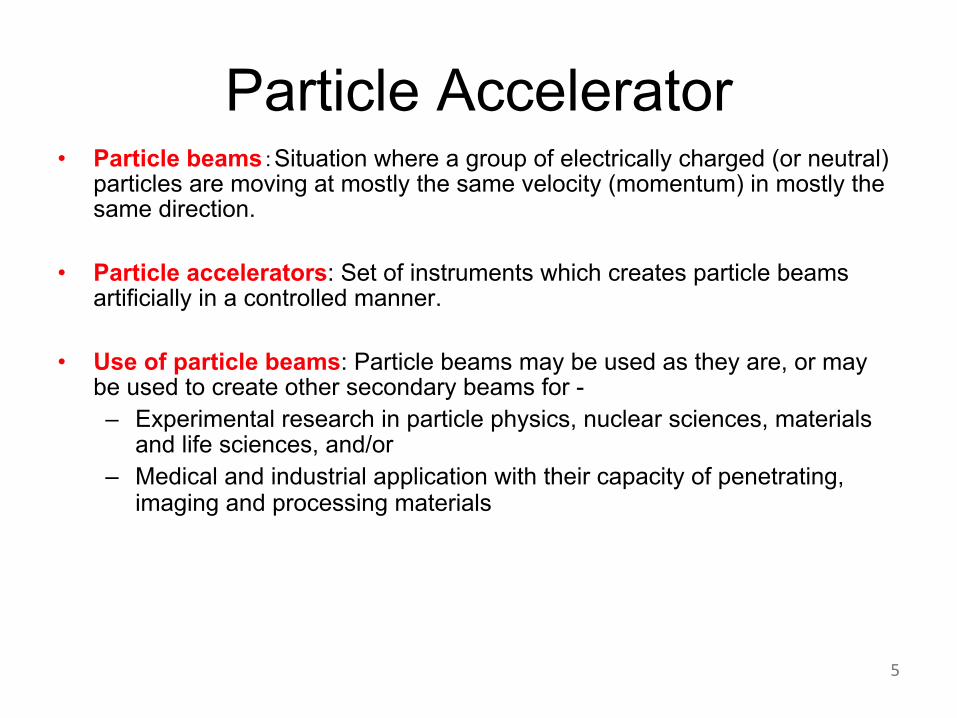
Particle Accelerator• Particle beams5Situation where a group of electrically charged (or neutral)
particles are moving at mostly the same velocity (momentum) in mostly the same direction.
• Particle accelerators: Set of instruments which creates particle beams artificially in a controlled manner.
• Use of particle beams: Particle beams may be used as they are, or may be used to create other secondary beams for -
– Experimental research in particle physics, nuclear sciences, materials and life sciences, and/or
– Medical and industrial application with their capacity of penetrating, imaging and processing materials
5

Particle Accelerator• Use of particle beams: Particle beams may be used as they are, or may be used to
create other secondary beams for -
– Experimental research in particle physics, nuclear sciences, materials and life sciences, and/or
– Medical and industrial application with their capacity of penetrating, imaging and processing materials
– Human control à Allows experiments under controlled conditions (Exemplary experimental sciences, with benefits and limitations.
– How many Nobel prizes where experiments with particle accelerators played decisive roles?
Ans511 cases out of 132: 21 winners out of 203, as of 2017
• Particle accelerators are a subject of research and development on their own
– New regimes of particle energies or particle numbers can be realized only by the efforts of accelerator builders – you have to do it yourseves.
– 3It of course, means collaborative work with other fields and industries is essential – you have to work with other people.
6

Real Basics
• Energy / Momentum
– Non-relativistic:
– Relativistic:
– Speed of light: c = 2.9979 108 m/s
– Forces on charged particles:
– And when the B is UP, the electrons go to the LEFT.
– Unit of energy: eV (electron-volt)
keV (103), MeV (106), GeV (109), TeV (1012)
Unit of momentum: eV/c (electron-volt/c)
7
mvpmvE == ;21 2
2
22242
1/1 ;/
;
bgb
gbg
-==
==+=
cv
mcpmccpcmE
)( BvEqF!!!!
´+=

Particle Acceleration
• It means to increase the kinetic energy of a particle.
• Charged particle attains an additional kinetic energy as it passes through a space with electric field
• Electron Volt
– 1eV = Kinetic energy attained across a potential gap of 1V
Electric charge of an electron = 1.602 10^-19 C
1 eV = 1.602 10^-10 J
– Velocity of an electron with kinetic energy 1eV ?
E = mv^2/2, where an electron mass m = 9.1 10^-31 kg ,
1 eV = 1.602 10^-19 = 9.1 10^-31 v^2 / 2
v = 5.9 10^5 m/s
v/c = 5.9 10^5 / 2.9979 10^8 = 0.002
Velocify of a proton with kinetic energy 1000 eV ?
8

��+-$�& ���� & +�-)+,��-������,.%.��
9
Mainly electrons and positrons
Photon Factory
e-/e+ Linac
SuperKEKB
Belle-II Detector
Slow e+ facility
10
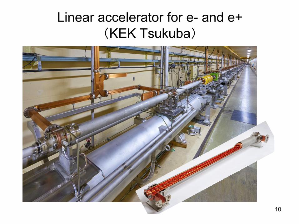
Linear accelerator for e- and e+3KEK Tsukuba4

Linear accelerator for e- and e+3KEK Tsukuba4
11

12
Accelerator System - SuperKEKB
Electron Source
Linear Accelerator (Linac)
Linear Accelerator (Linac)
Bending Section
Straight Section
Counter-travelling e- (7GeV; Blue) and e+ (4GeV; Red) beams are made to collide repeatedly at a single collision point –Goal: Max the particle collision rate.
http://www-acc.kek.jp/KEKB/index.html
Accelerator Cavities
Positron Source
Detector Facility for HEP Experiment
Positron Damping Ring
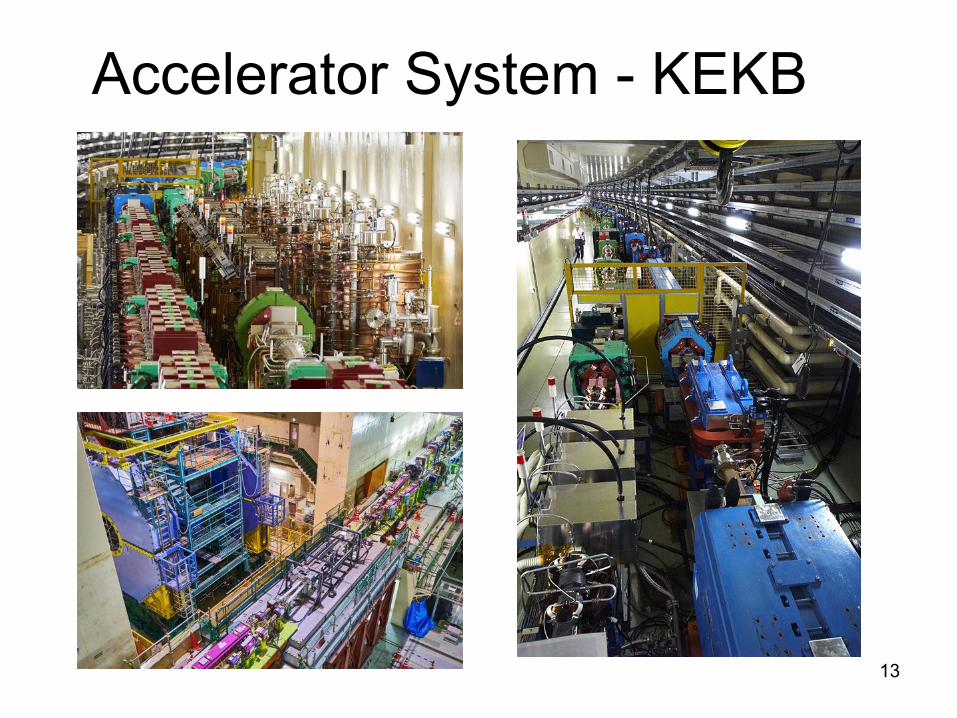
Accelerator System - KEKB
13

14Belle-II detector at SuperKEKB
First hadronic event that was observed at Belle-II (April 26, 2018)

15
Accelerator System – Light Source Rings
Hard X-ray stations
Soft X-ray stations
PF Ring (2.5 – 3GeV)AR Ring (6 – 6.5 GeV)
Store only the electrons to produce SR light (X-rays) for experiments.
Goal: Max support user experiments with SR of desired characteristics.
http://pfwww.kek.jp/outline/pf/pf1.html

16
Accelerator System – Light Source Rings
Exp hall at the KEK Photon Factory

Accelerators at KEK Tsukuba
Facility Primary Beam Use Application
SuperKEKB Electron, Positron
Collision High energy physics
PF Electron Synchrotron radiation Material + life sciences
PF/AR Electron Synchrotron radiation
Electron, Positron Injector
Electron, Positron
Delivery to SuperKEKB, PF, PF/AR
CompactERL Electron Synchrotron radiation R&D of new SRsource
ATF Electron Beam studies R&D of Beam handling for ILC
STF Electron SRF cavity R&D R&D for SRF beam acceleration
17

18
Accelerator System – J-Parc3GeV Synchrotron
(0.4 à 3GeV; 333µA
1MW, 25Hz)
50GeV Synchrotron – 15µA
Linac (0.4-0.6GeV; 15µA, 500µs,
50Hz)
Neutrino Exp Fac.
Hadron Exp
Mat / Life-science exp
To Super-Kamiokande
Accelerator-Driven
Transmutation Fac.
High-power proton accelerator to concurrently support numerous user experiments spanning over material / life / nuclear and particle. Goal: Reliable delivery of high-current proton beams.
http://www.j-parc.jp

Accelerator System – J-Parc
19

T2K Experiment(T2K = Tokai à Kamioka)
20
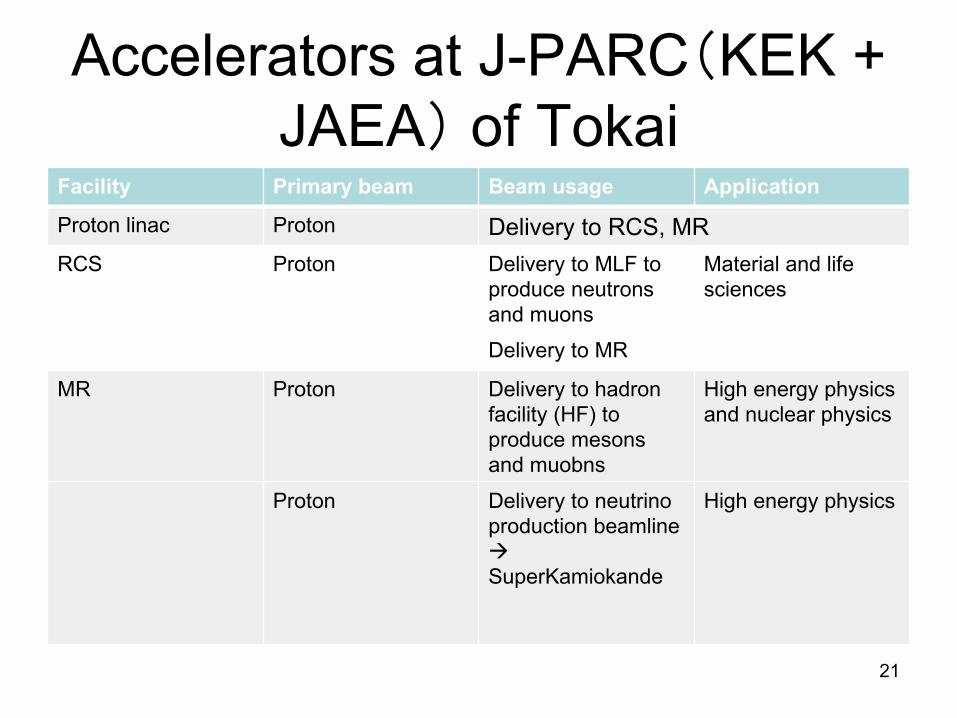
Accelerators at J-PARC3KEK + JAEA4 of Tokai
Facility Primary beam Beam usage Application
Proton linac Proton Delivery to RCS, MR
RCS Proton Delivery to MLF to produce neutrons and muons
Material and life sciences
Delivery to MR
MR Proton Delivery to hadron facility (HF) to produce mesons and muobns
High energy physics and nuclear physics
Proton Delivery to neutrino production beamline àSuperKamiokande
High energy physics
21

22
Accelerator System – Linear Collider
Accelerate electron beam and positron beam with two linear accelerators, and have them collide head-on at the beam collision point at the center for experiments in HEP.
Goal: Max the energy reach, max the beam interaction rate.
Check the movie at http://bit.ly/dutCx0 for visual effects.
https://www2.kek.jp/ilc/ja/
250GeV e- on 250GeV e+; Rep rate = 5Hz

23
Accelerator System –Energy Recovery Linac (ERL)
Electron source
Injector
Accelerator C
avities
(Superco
nducting)
Beam dump
Undulat
or m
agne
ts a
s lig
ht
sour
ce
ERL is similar to light source rings in that it utilizes light emission off electron beam as it goes through undulator magnets.
Differences (and advantages), however, include:
+ one-time use of beam, i.e like linear accelerator
+ opportunities for very bright, very short light pulses
+ energy recovery
http://pfwww.kek.jp/ERLoffice/
“CompactERL” prototypeE ~ 35-245 MeV; I ~ 10 mA; ge ~ 0.1 – 1 mm ; st ~ 100fs rms
Proposal for “Real” ERLE ~ 5GeV; I ~ 10 - 100mA ; ge ~ 10 – 100 pm; st < 100fs rms

Basics (1)
• Energy and momentum of material particles:
– Non-relativistic case, where velocity v is much smaller thanspeed of light c -
– Relativistic case:
Where,
– Speed of light: c = 2.9979 108 m/s
24
mvpmvE == ;21 2
2
2
2222242
1/1 ;/
1/
1/
bgb
bbgb
bg
-==
-==
-==+=
cv
mcmcp
mcmccpcmE

Basics (2)• Simplified special relativity
! = #$ , % = &
&'()
* = +,-%
Knowing
! = 1 − 1%-
If 0 ≪ , ,γ ~ 1 + ()- . So,
*~+,- 1 + !-
2 = +,- + 12+0-
25
Basics (3)
26

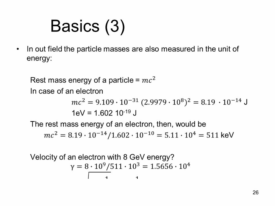
Basics (3)• In our field the particle masses are measured in the unit of energy
Rest mass energy = +,-For electrons:
+,- = 9.109 9 10':& (2.9979 9 10=)- = 8.19 9 10'&@ J
1eV = 1.602 10-19 J
Rest mass energy of an electron is
+,- = 8.19 9 10'&@/1.602 9 10'&C = 5.11 9 10@ = 511 keV
Velocity of an 8GeV electron?γ = 8 9 10E/511 9 10: = 1.5656 9 10@
! = 1 − 1%- ~1 −
12%- = 1 − 2 9 10'E
27
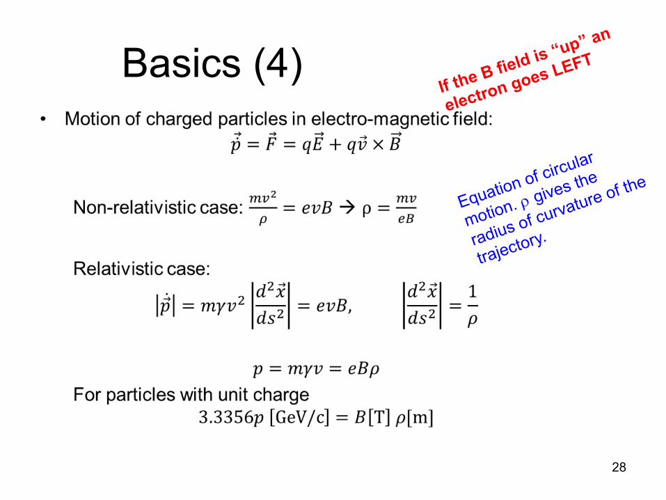
Basics (4)
28
If the B field is “up” an
electron goes LEFT
Equation of circular
motion. r gives the
radius of curvature of the
trajectory.

Creating a particle beam?
• Electrons and protons are abundant in materials. Yet they are usually in bound states.
• To create electron/proton beams means
– To unbound them, and
– To bring them into the state suitable for handling with particle accelerators.
• Particles which don’t exist naturally (for instance, positrons) need to be artificially created.
29

Electron Source (Example)
30
Thermionic Gun: Thermal electrons are extracted from a cathode which is set at a negative HV and is being heated.
Electrons

31

Electron source324
32RF electron gun for the electron/positron linac at KEK Tsukuba.

Positron source
33
Bring high energy electron or photon beams on high-intensity target (tungsten etc) and let them produce electromagnetic showers.
Pick up positrons produced in e+e- pair creation (threshold energy = 2 x 511keV)
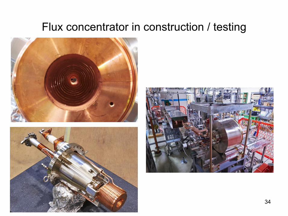
Flux concentrator in construction / testing
34

Positron Source• Flux Concentrator (FC) is a device which is used as OMD (Optical Matching Device)
in a positron production system. FC can produce strongly focused ~solenoid field (6-10T) out of eddy current that is induced by pulsed primary coil current on its outside. However, FC, generally is limited in its pulse length (< 30 µs).
• Other devices to use as OMD include: – AMD (adiabatic matching device) – a solenoid magnet with adiabatically changing field
strength; – QWT (quarter-wavelength transformer) – a short strong solenoid followed by a weaker
solenoid; – LL (Lithium lens).
They can replace FC for longer pulses but at lower magnetic field, or require additional R&D.
T.Kamitani
36
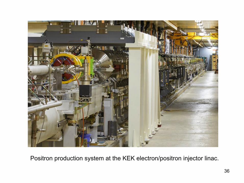
Positron production system at the KEK electron/positron injector linac.

Proton Source
• Out of H2, you can either create p or H-, but for
– Ease of attaining a high current, and
– Ease of handling during injection in the booster synchrotron,
It is advantageous to use H- (p with two electrons) in the upstream end of a proton accelerator system.
• J-PARC uses H-
– Filament (TaB6) discharge H- source in a Plasma ch. à
– Extraction of H- via three sets of electrodes (50kV in total) )
– à RF-Qs
• Electrons can be stripped off H-
easily later, when an accelerated H-
passes through thin foils.
37
H.Oguri et al
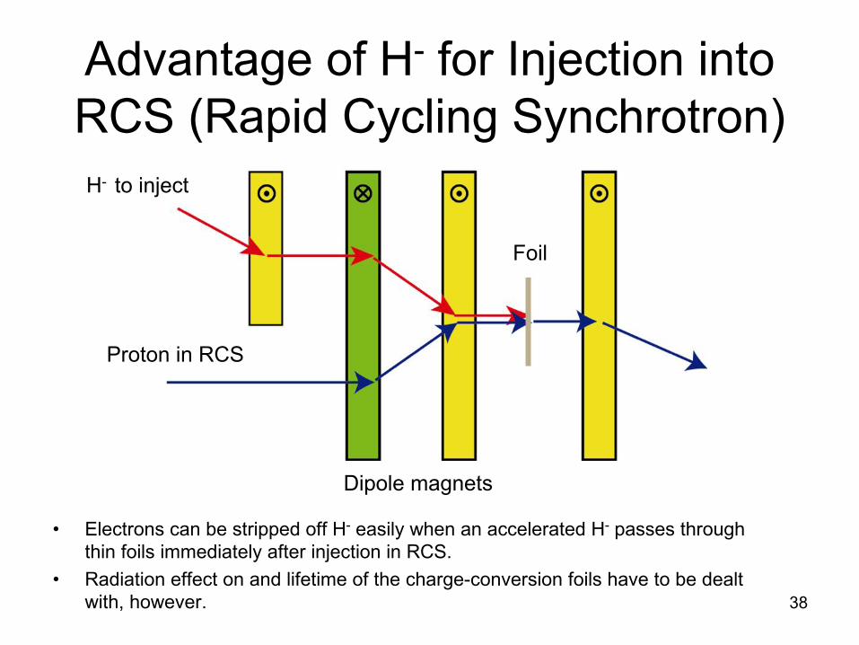
• Electrons can be stripped off H- easily when an accelerated H- passes through thin foils immediately after injection in RCS.
• Radiation effect on and lifetime of the charge-conversion foils have to be dealt with, however. 38
H- to inject
Proton in RCS
Advantage of H- for Injection into RCS (Rapid Cycling Synchrotron)
Foil
Dipole magnets

How to control the motion of charged particle beams?
• Charged particles,
– Once they are accelerated to certain energies,
– Will continue straight motions unless they collide with other material particles.
• To change their direction of motions, we use
– Electric or magnetic fields
– More often the magnetic fields for their ease of use.
39

Dipole Magnets• Dipole magnets are the primary tools to control the
orbit of beam particles.
– Big dipole magnets to define the orbit are often called “bend magnets”.
– Small dipole magnets for orbit correction are often called “correctors.”
• Lorentz force formula: F = evB
– Remember: When the field is UP, an electron goes to the left, a positron (or proton) goes to the right.
• Q4: Prove 3.3356p [GeV] = B [T] r [m]
Electron is going counter-clockwise in ATFDamping ring. Is the B field up or down?
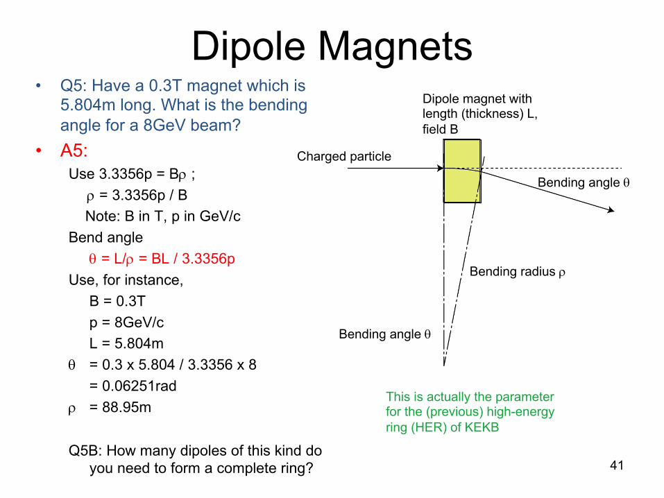
Dipole Magnets• Q5: Have a 0.3T magnet which is
5.804m long. What is the bending angle for a 8GeV beam?
• A5:Use 3.3356p = Br ;
r = 3.3356p / B
Note: B in T, p in GeV/c
Bend angle
q = L/r = BL / 3.3356p
Use, for instance,
B = 0.3T
p = 8GeV/c
L = 5.804m
q = 0.3 x 5.804 / 3.3356 x 8
= 0.06251rad
r = 88.95m
Q5B: How many dipoles of this kind do you need to form a complete ring? 41
This is actually the parameter for the (previous) high-energy ring (HER) of KEKB
Dipole magnet with length (thickness) L, field B
Charged particle
Bending radius r
Bending angle q
Bending angle q

Dipole MagnetsQ6: LHC now has beam momentum 3.5 TeV. Ring circumference is 27km. What is the required B, if the whole ring is completed packed by dipole magnets?
A6:
• r = C / 2p= 27000 / (2 x 3.14)
= 4297.2 m
• Remember, 3.3356p = Br• B = 3.3356p / r
= 3.3356 x 3.5e3 / 4297.2
= 2.72T
Q7: The LHC dipoles are actually running at ~4.2T for 3.5TeV beam. What is the “dipole packing factor?”
A7:
• Remember, 3.3356p = Br• Bending radius in dipoles with B = 4.2T
would be
r = 3.3356p / B
= 3.3356 x 3.5e3 / 4.2
= 2779.7 m
• Total length to occupy with dipoles would be
2 p r = 2 x 3.14 x 2779.7
= 17.465 km
• Packing factor
= 17.5e3 / 27e3 = 65%
(Actually LHC has 1232 units of dipoles, each 15m long) 42

• Quadrupole (quad) magnets are the primary tools for focusing the beam, or for stabilizing the beam orbit around its center.
• By = Gx; Bx = -Gy
• G = field gradient [T/m]
• If quad is focusing in x, it is de-focusing in y.
• Pole field is ~ 1.4 a G where “a” is the aperture radius of the magnet.
• Q8. Prove that a quadrupole magnet with field gradient G and length L would provide a particle of momentum p with a focal length F that is given by: F = 3.3356p / (GL)
43
x
y
a
Quadrupole Magnets
ATF2
×

Quadrupole Magnets
44
A8.
GLp
pxGLxxF 3356.3
3356.3/ =
×==
q
xp
GLL3356.3
angle Bend ===r
q
x
q
q
Focal length: F
Gxp3356.3:radius Bend =r

Single-Particle Optics
• We saw that a thin quad magnet (GL) acts like a focusing / defocusing lens with
F = 3.3356p/(GL).
What if you had a series of such magnets spaced apart by L ?
(NB: That L is different from that within (GL); sorry about the confusing notation.)
• Let us characterize the particle trajectory in x with a “vector”
(x, x’).
x is the location of the particle and
x’ is the angle of the trajectory, i.e.
x’ = dx / ds
where s denotes the coordinate along the canonical trajectory.
In the following discussion, we ignore particle acceleration for simplicity.
• One sees that if there are no magnetic components along the beamline, after a length of s, the (x, x’) of the particle would be like,
x(s) = x(0) + s x’(0)
x’(s) = x’(0)
So in vector notation,
• What is the effect of a thin quad (e.g. ignore the thickness) with focal length F on (x, x’)?
The quad does not change x, but does change x’ by x’ à x’ – x/F
We call matrices like these “beam transfer matrices”.
÷÷ø
öççè
æ÷÷ø
öççè
æ=÷÷
ø
öççè
æ)0(')0(
101
)(')(
xxs
sxsx
beforeQafterQ xx
Fxx
÷÷ø
öççè
æ÷÷ø
öççè
æ-
=÷÷ø
öççè
æ'1/1
01'
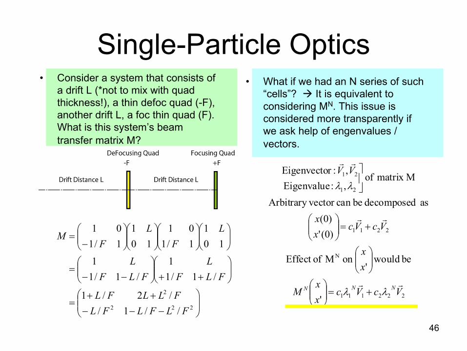
Single-Particle Optics• What if we had an N series of such
“cells”? à It is equivalent to considering MN. This issue is considered more transparently if we ask help of engenvalues / vectors.
46
• Consider a system that consists of a drift L (*not to mix with quad thickness!), a thin defoc quad (-F), another drift L, a foc thin quad (F). What is this system’s beam transfer matrix M?
÷÷ø
öççè
æ
---++
=
÷÷ø
öççè
æ++÷
÷ø
öççè
æ--
=
÷÷ø
öççè
æ÷÷ø
öççè
æ÷÷ø
öççè
æ÷÷ø
öççè
æ-
=
222
2
//1//2/1
/1/11
/1/11
101
1/101
101
1/101
FLFLFLFLLFL
FLFL
FLFL
LF
LF
M
222111
N
2211
21
21
'
be would'
on M ofEffect
)0(')0(
as decomposed becan vector Arbitrary
Mmatrix of ,:Eigenvalue,:rEigenvecto
VcVcxx
M
xx
VcVcxx
VV
NNN!!
!!
!!
ll
ll
+=÷÷ø
öççè
æ
÷÷ø
öççè
æ
+=÷÷ø
öççè
æ
úû
ù

Single-Particle Optics• So, if
(Tr M / 2)2 < 1
-1 < 1 – L2/2F2 < 1, i.e.
| L / 2F | < 1
Then the eigenvalues will be complex. Since l1 l2 = 1, they can be written as
l1 = e –iµ, l2 = e +iµ
and
MN will not be divergent!
à Principle of FoDo lattice.
Q9: We have magnets with G = 1T/m, thickness 0.5m. Let us set the half cell length of FoDo to be 5m (full length 10m). For which momentum range can this beamline act as a non-divergent FoDo?
Q10: How would all the analysis above change, if we do NOT ignore the thickness of the quads?
47
• So the question reduces to evaluating the eigenvalues of M. Recall the basic linear algebra.
Note: det M = 1, because all the transfer matrices of the “components” which contributed to M have their determinant 1.
divergent. is real, is if Hence,1
so
.1 where,
0 Thus,
0 of solutions are , sEigenvalue
21
21
2
21
NM
TrM
M
MTrM
IM
l
llll
ll
lll
==+
=
=+×-
=-

FoDo Lattice Examples
48
Beamline of ATF2
ATF damping ring

The Beam• How does one characterize the transverse
spread of the beam, i.e. that of a group of many particles?
– Consider an ensemble of particles with distributed (x, px), measured from the beam centroid.
– Take (x, px) as the canonically conjugate variables of motion, and take it that they consitute the “Phase Space” of the group of particles.
– If acceleration is ignored, (x, x’) can serve the purpose instead of (x, px).
– Same goes for (y, py) and (z, E).
• So, take the area occupied by particles in the (x, x’) plane (it is a virtual plane) , and call it - “Beam Emittance in x”.
– Dimension of transverse beam emittance is, thus, (m),
49
• Systematic analysis of all these in practical beamlines requires much elaboration of single-particle motions, starting from the previous pages. My lecture cannot really cover this critical topic at all! Trust that Ohmi san’s lecture covers it in detail.

• Iron saturates at ~ 2T. This gives limitation to the field strength achievable with normal-conducting iron-dominated (NC) magnets. For instance, dipole magnets with B > 1.5 T, or quadrupole magnets with a G > 1T (a is the “aperture” of the quad) should go “superconducting” (SC).
• SC magnets, without iron, can produce higher field. But, because of the absence of the iron poles, one has to carefully arrange the electric current distribution to produce the desired field pattern. à Lecture by Tsuchiya
• SC magnets, with iron, is, again, limited in strength, similarly to NC magnets. However, they are substantially lower power consuming.
Superconducting Magnets

QCS for SuperKEKB
51

Magnets - Comments• Generally, Maxwell’s equation allows solutions of
many higher order fields besides dipole and quadrupole fields (sextupole, octapole, decapole, dodecapole etc).
• Such fields are sometimes useful for beam controls; They are also sometimes very harmful.
• It is important to control the higher pole field. This leads to tolerance issues of the magnetic poles (NC) or current distribution (SC).
• Thermal effects and mechanical aspects are also important issues for practical magnet designs and operation.
• Survey and alignment of the magnets are critical tasks to do before starting operation of a new accelerator.
• Finally, magnet power supplies (settability, stability and lifetime) are a very important area which is sometimes overlooked.
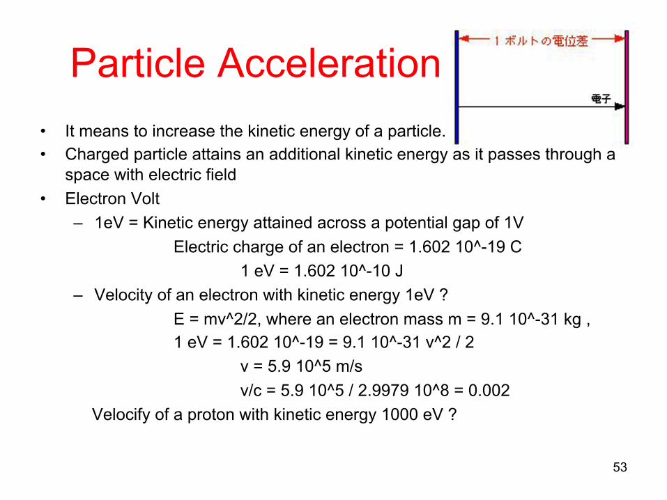
Particle Acceleration
• It means to increase the kinetic energy of a particle.
• Charged particle attains an additional kinetic energy as it passes through a space with electric field
• Electron Volt
– 1eV = Kinetic energy attained across a potential gap of 1V
Electric charge of an electron = 1.602 10^-19 C
1 eV = 1.602 10^-10 J
– Velocity of an electron with kinetic energy 1eV ?
E = mv^2/2, where an electron mass m = 9.1 10^-31 kg ,
1 eV = 1.602 10^-19 = 9.1 10^-31 v^2 / 2
v = 5.9 10^5 m/s
v/c = 5.9 10^5 / 2.9979 10^8 = 0.002
Velocify of a proton with kinetic energy 1000 eV ?
53

DC Acceleration
54
Cockroft-Walton generator circuit.Cockroft-Walton accelerator.KEK has one, too, for 12GeV protronsynchroton, completed in 1976.
Good for up to a few hundred KeV.

KEK’s Cockcroft-Walton Generator
55

Problem with DC acceleration
56
- Electrons as represented by the green bunch can be accelerated.
- Electrons as the red bunch cannot be accelerated.
- Generally it is near impossible to use DC electric field for repeated acceleration of the same bunch.
Can be
accelera
ed
Cannot be
accelera
ted

Repeated acceleration with AC field
57
Oscillating field
Hollow metallic pipe
time t =0
time t =½ of field cyecleFigs from M.W.Poole
- Problem with the DC field (impossibility of repeated particle acceleration) can be solved by
- Use of alternating electric field whose polarity cycles between positive and negative at a certain period.
- i.e. use of AC electric field.
- IFF the arrival of charged particles and the switching AC phase are in adequate synchronization.
- Of course, particle trajectories have to be suitably arranged.

Particle acceleration with AC field
58
Cyclotron:
For non-relativisitic velocity v,F = evB = mv2/reB = mv / r
Period of circular motion of proton, T,turns out to be constant
T = 2 pr / v = 2 p m / eB
If the AC period and T are the same, repeated acceleration can be realized.
Mag field
Protons
N pole of a magnet
S pole of a magnet
ACsource

Early cyclotron in Japan
59
#2 cyclotron at RIKENIn 1943.Diameter of the magnet 150cm
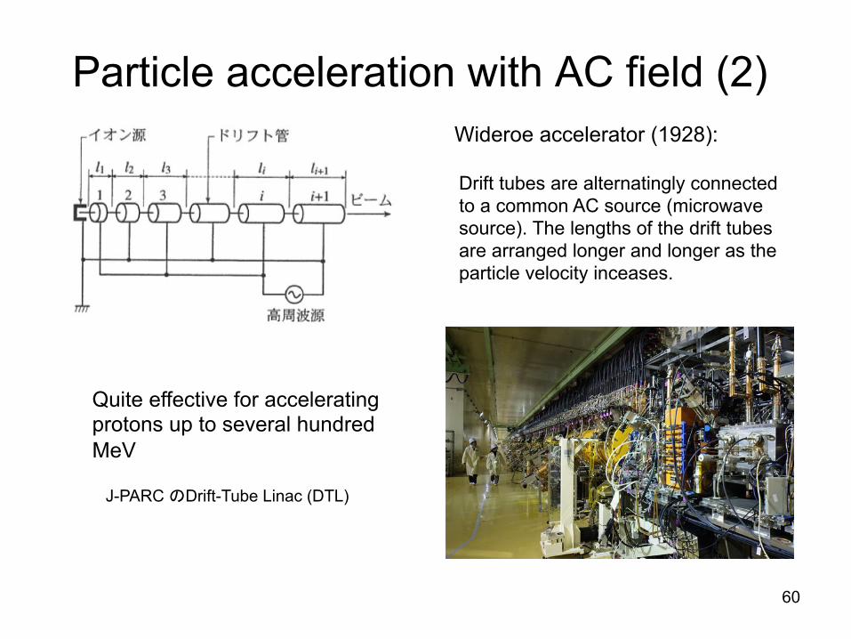
Particle acceleration with AC field (2)
60
Wideroe accelerator (1928):
Drift tubes are alternatingly connected to a common AC source (microwave source). The lengths of the drift tubes are arranged longer and longer as the particle velocity inceases.
J-PARC 2Drift-Tube Linac (DTL)
Quite effective for accelerating protons up to several hundred MeV

Repeated acceleration
• To realize repeated acceleration, the AC field needs to be used with very accurate synchronization between5
– Circular motion of particles (ß particle path length / particle velocity)
– Switching of accelerating field (ß AC frequency and the phase)
Very important point. Otherwise, it won’t work.
• Control of all relevant parameters are a crucial issue.
61
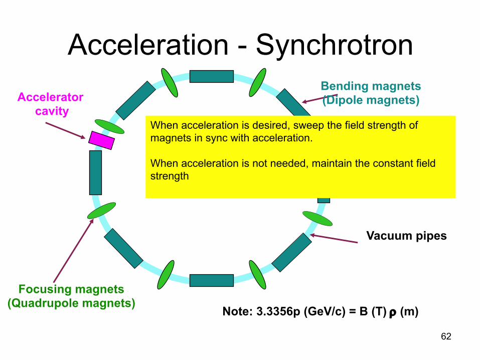
Acceleration - Synchrotron
62
Focusing magnets(Quadrupole magnets)
Vacuum pipes
Acceleratorcavity
Bending magnets(Dipole magnets)
Note: 3.3356p (GeV/c) = B (T) r (m)
When acceleration is desired, sweep the field strength of magnets in sync with acceleration.
When acceleration is not needed, maintain the constant field strength

Example – Proton synchrotron (30GeV) at J-PARC
63
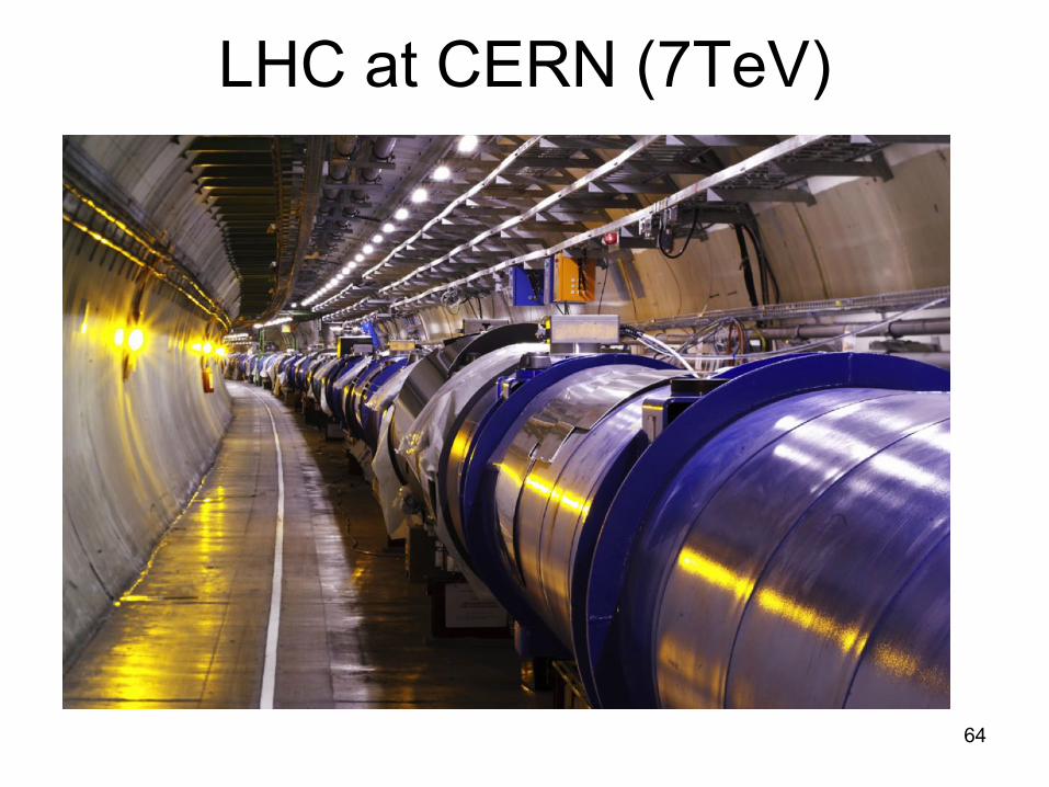
LHC at CERN (7TeV)
64

LHC Operation Log
65CERN

Synchrotrons, Store rings, Colliding rings
66
• Nearly all ring accelerators require some beam acceleration for– Actually increasing the beam energy and/or
– Compensate for beam energy loss due to synchrotron radiation
• Some ring accelerators are called “storage rings” as their mission is to hold the ring for a long period.
• Some facility use a pair of ring accelerators to collide two opposing beams in an experimental hall – Colliding rings (colliders).
Energy change in the rings?
Storage type?
Colliding type?
SuperKEKB No Yes Yes
J-PARC MR Yes No No
LHC MR Yes Yes Yes

67
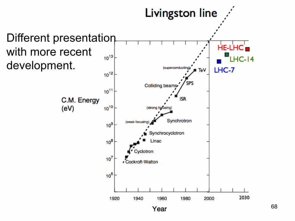
Livingston Chart
By Stanley Livingston (1954)
Historical evolution of the beam energies.
�
68
Different presentation with more recentdevelopment.

S-band accelerator structure for use at KEK injector linac
69
This is a cut-away model for display.

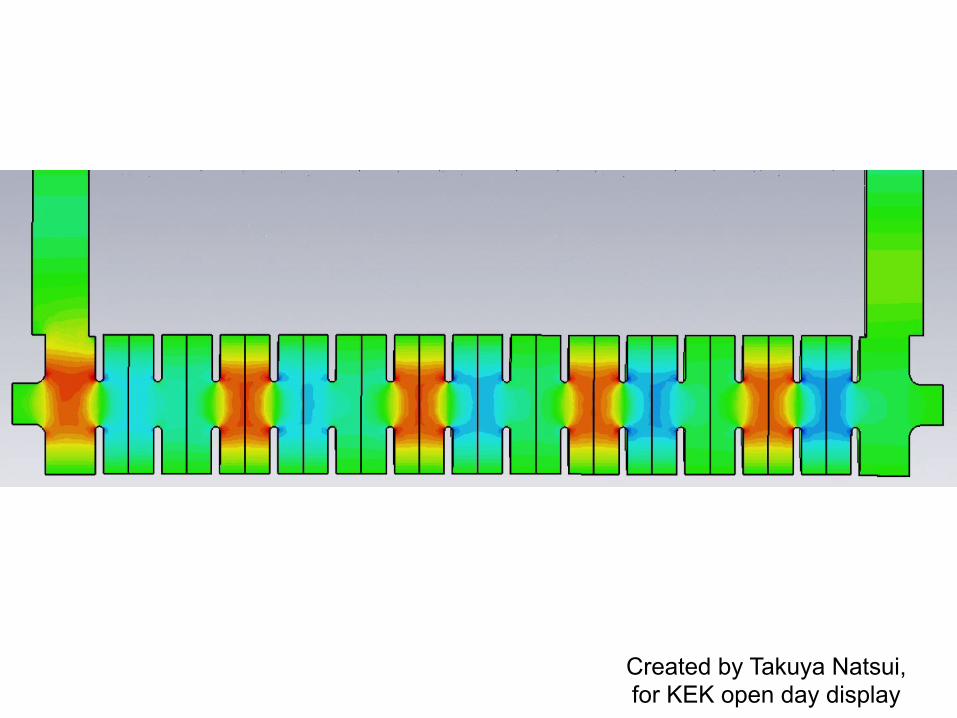
Travelling Wave Accelerator Structure (2p/3)
Created by: Takuya Natsui(KEK)
Created by Takuya Natsui,for KEK open day display
Created by: Takuya Natsui(KEK)
Created by Takuya Natsui,for KEK open day display

Accelerator Resonant Cavity(Multi-cell Superconducting)
72
If the time that it takes the beam particleto travel across one cell coincides with one half of the RF period, the particle will be continually accelerated, in case of aso-called p-mode standing-wave structure.
Niobium 9-cell cavity

Acceleration with Resonant Cavities• Single-cell “pillbox” cavity: by solving
Maxwell’s equation one obtains –
• Where,– c01 = 2.4048
– w010 = c01 c / b
• This is called TM01 mode (fundamental mode, TM010 to be more exact) of a pillbox cavity.
73K.Takata
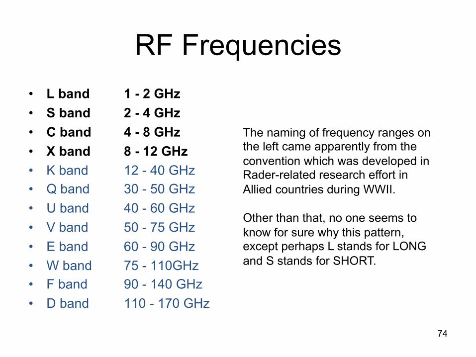
RF Frequencies
• L band 1 - 2 GHz• S band 2 - 4 GHz• C band 4 - 8 GHz• X band 8 - 12 GHz• K band 12 - 40 GHz
• Q band 30 - 50 GHz
• U band 40 - 60 GHz
• V band 50 - 75 GHz
• E band 60 - 90 GHz
• W band 75 - 110GHz
• F band 90 - 140 GHz
• D band 110 - 170 GHz
74
The naming of frequency ranges on the left came apparently from the convention which was developed in Rader-related research effort in Allied countries during WWII.
Other than that, no one seems to know for sure why this pattern, except perhaps L stands for LONG and S stands for SHORT.

Resonant Cavities• Quality factor (Q-value) of a cavity:
– [stored energy in the cavity] / [energy loss over 1rad of RF oscillation]
• In case of a TM01 mode, the stored energy in a pillbox cavity is
• Surface current in the cavity is
• Ohmic energy loss is surface integral of rsJ2/2 -
75
25.021~)(
21
21 2
000121
200
20 ´== ò VEVJEdVEU ecee
titi erc
JcEerBBJ ww
qw
µµµ÷øö
çèæ=== 1
0
000
1)(11
)(1221
22221
01212
0120
20
210
21
2
0
0
cc
pr
wpwpµ
r
Jdbbd
ZE
dbbdJrdr
crJ
cEP
s
b
s
úû
ùêë
é+=
úû
ùêë
é÷øö
çèæ+÷
øö
çèæ×÷÷
ø
öççè
æ=D ò

Resonant Cavities• From the previous page, the Q value that we seek is given by
• In case of copper Q ~ 5000, in case of superconducting Nb Q ~ 1010
76
÷÷ø
öççè
æ+
=D
=
2201
001
12dbcU
PQ
s cr
µcw

Resonant Cavities
• Shunt impedance Rs of an accelerator cavity is defined as
Rs = (Energy gain V0 by a particle across the cavity)2 / DP
• For a pillbox cavity the Rs is given by
• Where “T” is the transient factor.
• In case of copper: Rs = 15-50MW/m for 200MHz, 100MW/m for 3GHz 77
÷øö
çèæ
÷øö
çèæ=
÷øö
çèæ
=
÷÷ø
öççè
æ+
=
òvd
vd
dE
dzvzE
T
TJ
dbb
dZR
d
ss
2/
2sin
2
cos
)(11
1
0
2/
00
2
01212
01
20
www
cc
pr
UV
QRs
w
20=
Geometric quantity of a cavity.

Superconducting Cavity at superKEKB
78
79
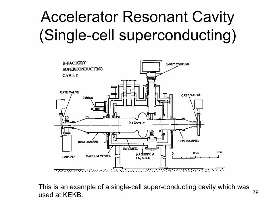
Accelerator Resonant Cavity (Single-cell superconducting)
This is an example of a single-cell super-conducting cavity which wasused at KEKB.

Accelerator Cavities / Structures
• Q2: If fRF = 1.3GHz for a p-mode cavity, what should be the cell length?
• A2:
f = 1.3E9 Hz; c = 2.9979E8 m/s
à l = c/f = 0.23 m;
p-mode cell length = l/2 = 0.12 m
• Q3: If fRF = 2.856GHz for a 2p/3-mode structure, what should be the cell length?
• A3:
f = 2.856E9 Hz; c = 2.9979E8 m/s
à l = c/f = 0.105 m;
2p/3-mode cell length = (2/3)l/2 = 0.035m
80

Accelerator Cavity / Structure -Comments
• Cavities have many resonant modes. TM01 is the lowest and is most often used for beam acceleration. But,
– Higher-order modes, such as TE11, also can be excited with an external RF source,
– Or by the beam that traverses through them off axis,
– And do some harms. This may not be big problems for many applications, but it is for some.
81
TE11 mode (~1.5 x TM01)
T.Higo, et al

Accelerator Resonant Cavity (Single-cell normal conducting)
82
This is an example of a single-cell normal conducting cavity (which is used at superKEKB. It has “slots” for removing (damping) HOM, as excited by the beam, which are harmful for multi-bunch beam operation, and an energy storage cavity to reduce the effects of beam loading on the system.
T.Abe

Accelerator Cavity / Structure -Comments
• Design, engineering and operation of accelerator cavities / structures is a huge area.
– Exact evaluation of resonant frequencies, shunt impedance and quality factor have to be made through numerical calculations (still, an intuitive understanding important).
– Size variation à variation of resonance frequencies à mechanical tolerance and tuning issues. Similarly, temperature stabilization issues. (Q: if DT = 5deg, how much energy shift for an X-band structure?)
– “Couplers” to let the external RF power into the cavities and vice versa.
– In pulsed mode operation, the accelerator cavities exhibit transient behaviors at the beginning and end of RF pulses.
– Even in continuous wave operation, the accelerator cavities see transient effects when the beams pass through them.
83E.Kako, S.Noguchi et al

Microwave (RF) Source(Klystrons)
• For brevity, the solenoid beam focusing magnet is omitted from the illustration above.
• Klystron, in a way, is a reversed accelerator, which extracts RF power from the beam.
• Klystrons, depending on the type, operate in pulsed- or continual modes.
84
Velo
city
mod
ulat
ion
Inte
nsity
mod
ulat
ion
All
part
icle
s sa
me
spee
d à
velo
city
m
odul
atio
n vi
a a
cavi
ty; r
epea
t
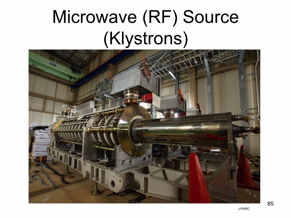
Microwave (RF) Source(Klystrons)
85J-PARC

Microwave (RF) Source(Modulator + Klystrons)
86Klystrons for pulsed operation
rModulator
T.Okugi
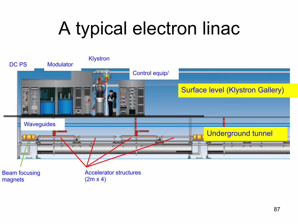
A typical electron linac
87
Surface level (Klystron Gallery)
Underground tunnel
KlystronModulatorDC PS
Waveguides
Accelerator structures(2m x 4)
Control equip/
Beam focusingmagnets

88
Microwave (RF) Source(Modulator + Klystrons)
Tsukuba injector linac

89

Microwave RF Source (Klystrons) -Comments
• As said in the previous page, klystrons are like small-scale reversed accelerator, and are more difficult ones at that.
– Relatively low beam energy (up to few hundred kV).
– High current (tens of A)
– So large beam power, and large space-charge effect.
– Large beam size.
– Opportunities for a good number of resonant behaviors, besides the RF power that you intend to produce.
• Design, engineering and operation of klystrons is a huge area, too, in a way similar to those for accelerator cavities / structures.
– RF calculations and simulations, under prominent effect of space-charge force.
– Tolerance and tuning issues.
– RF windows to isolate the klystron vacuum and outside vacuum. Sometimes a cause of trouble à another large area of studies which I cannot detail.
– Cathode lifetime. Klystrons are a consumable component. Significantly more so than accelerator cavities / structures.
90

Beam Monitors
• Strip-line Type Beam Position Monitors (BPM): with 4 electrodes, for use at ATF linac and extraction beamlines.
H.Hayano et al
• Generally,
x = k (SL – SR) / (SL + SR)
y = k (SU – SD) / (SU + SD)

Monitoring of beam orbit• Data from many beam position monitors plotted along the
direction of beam motion.
X
Y
Bunchcharge
~ 600m

Beam Monitors• Cavity Type Beam Position Monitors (BPM): Rather than seeing induced charges on
electrodes, measure the transverse modes (TE-modes) that are induced by the beam when it passes off center of a cavity.
KEK-Pohan-SLAC Collaboration

Beam Monitors• Beam Current Monitors: BPMs can
also measure the beam intensity but for better precision a dedicated beam current monitor is used, as shown on the right.
• Beam Profile Monitors with phospho-screens:
– Direct measurement of the beam, in case of linac or beamlines.
– Measurement of synchrotron radiation light in case of rings (on the right).

Beam Monitors• Beam Profile Measurement with
interference method of SR light in rings.
– Take advantage of the interference of SR light which comes through a slit pair.
– Overcomes the diffraction limit in standard SR measurement.
a = beam size; g = “visibility” (clearness)
l = wavelength; D = slit separation
L0 = distance from the light emission point
T.Mitsuhashi and T.Naito

Beam Monitors• Beam Profile Measurement with
Wire Scanners in the linac or in the beamlines.
– Step the wire (or step the beam orbit) whose radius is assumed smaller than the beam size.
– Look at the signal, whose strength would be proportional to the intercepted beam.
– Profile the signal strength as function of the “stepping”.
– Fundamentally a multi-pulse operation. Subject to limitation due to wire breakage.
H.Hayano et al

Beam Monitors
• Beam size monitor with Compton scattering off interfering pattern of laser photon population.
• Data on left (2010/5) at ATF2:– Laser WL: 532 nm– Laser crossing: 3 deg– Fringe pitch: 3.81 µm– Modulation: 0.87– Beam size: 310 +/- 30 nm
T.Tauchi

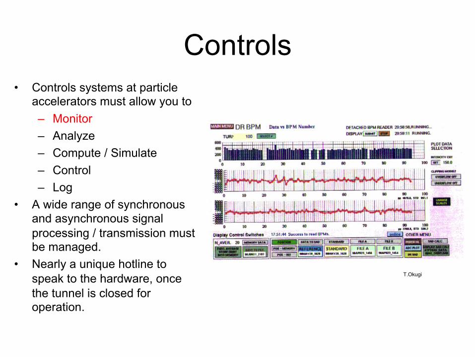
Controls• Controls systems at particle
accelerators must allow you to
– Monitor
– Analyze
– Compute / Simulate
– Control
– Log
• A wide range of synchronous and asynchronous signal processing / transmission must be managed.
• Nearly a unique hotline to speak to the hardware, once the tunnel is closed for operation.
Schematic diagram of KEKB control system (N.Yamamoto)
T.Okugi

Controls• Controls systems at particle
accelerators must allow you to
– Monitor
– Analyze
– Compute / Simulate
– Control
– Log
• A wide range of synchronous and asynchronous signal processing / transmission must be managed.
• Nearly a unique hotline to speak to the hardware, once the tunnel is closed for operation.
Schematic diagram of KEKB control system (N.Yamamoto)
N.Yamamoto

Conventional Facilities
KEK

Conventional Facilities• Sometimes the tunnel length becomes too
big to stay inside a lab campus.
– Going underground.
– Going off site.
– Safety issues.
• At any rate, you have to
– Fit all required beamline components in wherever they have to go.
– Connect them all either electronically, mechanically and vacuum-wise.
– Allow enough space for installation and maintenance activities, plus, survey and alignment sighting.
– Bring in fresh air and provide adequate cooling (taking the heat the out).
– Ensure safety for personnel and equipment.
EuroXFEL in Hamburg
LHC from satellite

Conventional Facilitiesf5200 mm
645 mm
EuroXFEL in Hamburg

Things that Beams would Do
105Accelerator is a device which overcomes, or takes advantages of these phenomena, to let the beam do what you like it to do.
Players Interaction via Effect
Material ßàBeam
Q.E Thermal electrons / Photo-emission / Ionization
EM / QED
Pair creation / Electro-magnetic shower
Absorption
Elastic / Inelastic scattering
Environment à Beam
Static E-Field Acceleration / Deceleration / Bending
Static B-Field Bending / Spin rotation
RF Field Acceleration / Deceleration / Bending
Beam à Environment Transient Field Fundamental mode RF / High-order mode RF
Heating
Beam ßà Light
Synchrotron Light emission
Radiation DampingCompton Scattering
QED Phenomena
Beam ßà BeamSpace-charge forces Within a single bunch
Beam-beam effects When two bunches cross each other
Physics Beam collision you look for
Beam à Env. à BeamLongitudinal EM Bunching / Debunching
Trasverse EM Emittance growth / instabilities / beam break-up
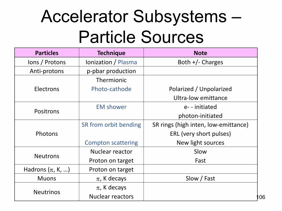
Accelerator Subsystems –Particle Sources
106
Particles Technique NoteIons / Protons Ionization / Plasma Both +/- ChargesAnti-protons p-pbar production
ElectronsThermionic
Photo-cathode Polarized / UnpolarizedUltra-low emittance
PositronsEM shower e- - initiated
photon-initiated
PhotonsSR from orbit bending SR rings (high inten, low-emittance)
ERL (very short pulses)Compton scattering New light sources
NeutronsNuclear reactor SlowProton on target Fast
Hadrons (p, K, …) Proton on targetMuons p, K decays Slow / Fast
Neutrinosp, K decays
Nuclear reactors

Accelerator Subsystems –Acceleration Section
107
Particles Energy (Kinetic) Range Technique
Ions / Protons
0 up to 1 ~ a few MeVCockroft
Ven de Graaf
< a few 100 MeVRF Qs
Drift-tube linaclow-b SC cavities
> a few 100 MeVlinac (NC, SC)Synchrotron
< several 10 MeV Cyclotron
Electrons
0 up to few hundred KeV Thermionic gun0 up to a few MeV RF gun
> a few 100 MeVlinac (NC, SC)Synchrotron

Accelerator Subsystems –Typical Beam Manipulation
108
��-$)( � 1��& ' (-,
��� & �+�-$)( ��� & +�-)+���/$-1
� � & +�-$)( ��� & +�-)+���/$-1
�.(�#$(" ��� & +�-)+���/$-1
� �'�-+�(,*)+- �)�) &�--$�
� �'�!)�.,,$(" ����).�& -��-+$*& -����)++ �-$)(,
�'$--�(� �+ �.�-$)( ���$�-$)(���'*$("������� �/$-1
�.(�#��)'*+ ,,$)( � (����������/$-1
�( +"1��)'*+ ,,$)( � (����������/$-1

Accelerator Subsystems –Beam Instrumentation
109
�.�(-$-1�-)�� �, � �'&$( ���+�0�+ �)- ,
� �'�*),$-$)(
�-+$*&$( ,�),-&1�-1*$��&
�.--)(,
�/$-$ , � 0��(��"+)0$("
� �'�$(- (,$-1
���,
��&&��.++ (-��)(
.++ (-��+�(,!)+' +
� �'�*+)!$&
��+ ( � �'�$(- +� *-$("��$(/�,$/
� -�&$� 0$+ � '$�$(/�,$/
��, +�0$+ ��$+&1�()(�$(/�,$/
���*+)!$& �$!!+��-$)(�&$'$-
���$(- +! + (�
��, +�!+$("
� �'�-$'$(" ���, ��,-� & �-+)($�,
�+)!��)(,�0��0)���, �- �%���' +�
110
Accelerators – Differences and Similarities
• You saw that accelerators vary widely in their organization, in accordance with their application, optimization, beam particles and size, but they also share similarities.
– Differences of accelerators come from
• differences of what you like to do with/to the beam.
– Similarities of accelerators come from
• common nature of particle beams that you deal with.
• Learning particle accelerators means for us to learn,
– To identify what you like to do with the beam and
– Find adequate technical solutions if they already exist and adopt them appropriately, or
– Develop new technical solutions if they do not exist.
– Now you have seen some such techniques.

111
Comments• Particle accelerators
– Consist of a number of subsystems for specific beam manipulation;– Use many components that do specific things with the beam. – Particle accelerators are a complex, almost organic system.
• Performance of particle accelerators
– Is determined by the performance of accelerator subsystems, – Whose performance is determined by that of individual components, – And the systems design which puts them together.
• Beam
– Is the object that you try to control and tame, but – The beam is also a friend who tells you what and how you are doing
right or wrong. – Be prepared to work with the beam.

112
Conclusions
• We tried a rather coarse, quick walk-through of subsystems of particle accelerators.
• If you wish to become expert on anything, all the subject matters introduced here must be more systematically and seriously re-surveyed.
• You have to read some textbooks (examples mentioned earlier), come to subsequent lectures in this course, solve problems on your own and so on.
• My sincere thanks go to Drs. K.Takata, T.Okugi, E. Kako, H. Hayano, J.Urakawa, M.Poole and many others, whose work I am freely taking advantage of, to create this note.