GENERAL - INSPECTION/CHECK - FedEx€¦ · general - inspection/check warning: before proceeding...
74
GENERAL - INSPECTION/CHECK WARNING : BEFORE PROCEEDING WITH MAINTENANCE WORK ON OR NEAR MECHANICAL FLIGHT CONTROLS OR PRIMARY FLIGHT CONTROL SURFACES, LANDING GEARS, ASSOCIATED DOORS OR ANY MOVING COMPONENT, MAKE CERTAIN THAT GROUND SAFETIES AND/OR WARNING NOTICES ARE IN CORRECT POSITION TO PREVENT INADVERTENT OPERATION OF CONTROLS. BEFORE POWER IS SUPPLIED TO THE AIRCRAFT MAKE CERTAIN THAT ELECTRICAL CIRCUITS UPON WHICH WORK IS IN PROGRESS ARE ISOLATED. BEFORE PRESSURIZING HYDRAULIC SYSTEMS, MAKE CERTAIN THAT HYDRAULIC SYSTEM UNDER MAINTENANCE HAS BEEN ISOLATED. 1. Check for External Leakage WARNING : CHECK THAT THE LANDING GEAR GROUND SAFETIES INCLUDING WHEEL CHOCKS ARE IN POSITION. BEFORE APPLYING OR RELIEVING HYDRAULIC SYSTEM PRESSURE, MAKE CERTAIN THAT THE TRAVEL RANGES OF THE CONTROL SURFACES ARE CLEAR. BEFORE PRESSURIZING HYDRAULIC SYSTEMS, CHECK THAT ALL CONTROLS ARE SET TO CORRESPOND WITH THE ACTUAL POSITION OF THE SERVICES THEY OPERATE. MAKE CERTAIN THAT RELEVANT CIRCUIT BREAKERS ARE OPEN, SAFETIED AND TAGGED BEFORE ATTEMPTING MAINTENANCE PROCEDURES ON ENGINE. INADVERTENT ENGINE START OR THRUST REVERSER OPERATION COULD RESULT IN DEATH OR SERIOUS INJURY TO PERSONNEL. A. Reason for the Job (1) To check the hydraulic systems and system components for leakage. (2) To check high and low pressure manifolds and ground service panels and manifolds for signs of external leakage. B. Equipment and Materials ITEM DESIGNATION (1) (2) Access Platform, 2.60 m to 6 m (8 ft. 8 in. to 19 ft. 8 in.) Access Platform, 6 m to 12 m (19 ft. 8 in. to 39 ft. 4 in.) P.Blk EFFECTIVITY: ALL 29-00-00-06 Printed - Date: 10/25/2012 Time: 10:14:12 Copyright © 2012 FedEx Express Corporation, Memphis TN, 38194, All rights reserved. Page 1 of 74 DEC 01/2011
Transcript of GENERAL - INSPECTION/CHECK - FedEx€¦ · general - inspection/check warning: before proceeding...

GENERAL - INSPECTION/CHECK
WARNING: BEFORE PROCEEDING WITH MAINTENANCE WORK ON OR NEARMECHANICAL FLIGHT CONTROLS OR PRIMARY FLIGHT CONTROLSURFACES, LANDING GEARS, ASSOCIATED DOORS OR ANY MOVINGCOMPONENT, MAKE CERTAIN THAT GROUND SAFETIES AND/ORWARNING NOTICES ARE IN CORRECT POSITION TO PREVENTINADVERTENT OPERATION OF CONTROLS.BEFORE POWER IS SUPPLIED TO THE AIRCRAFT MAKE CERTAINTHAT ELECTRICAL CIRCUITS UPON WHICH WORK IS IN PROGRESSARE ISOLATED.BEFORE PRESSURIZING HYDRAULIC SYSTEMS, MAKE CERTAIN THATHYDRAULIC SYSTEM UNDER MAINTENANCE HAS BEEN ISOLATED.
1. Check for External Leakage
WARNING: CHECK THAT THE LANDING GEAR GROUND SAFETIES INCLUDINGWHEEL CHOCKS ARE IN POSITION.BEFORE APPLYING OR RELIEVING HYDRAULIC SYSTEM PRESSURE,MAKE CERTAIN THAT THE TRAVEL RANGES OF THE CONTROLSURFACES ARE CLEAR.BEFORE PRESSURIZING HYDRAULIC SYSTEMS, CHECK THAT ALLCONTROLS ARE SET TO CORRESPOND WITH THE ACTUAL POSITIONOF THE SERVICES THEY OPERATE.MAKE CERTAIN THAT RELEVANT CIRCUIT BREAKERS ARE OPEN,SAFETIED AND TAGGED BEFORE ATTEMPTING MAINTENANCEPROCEDURES ON ENGINE.INADVERTENT ENGINE START OR THRUST REVERSER OPERATIONCOULD RESULT IN DEATH OR SERIOUS INJURY TO PERSONNEL.
A. Reason for the Job
(1) To check the hydraulic systems and system components forleakage.
(2) To check high and low pressure manifolds and groundservice panels and manifolds for signs of externalleakage.
B. Equipment and Materials
ITEM DESIGNATION
(1)
(2)
Access Platform, 2.60 m to 6 m
(8 ft. 8 in. to 19 ft. 8 in.)
Access Platform, 6 m to 12 m
(19 ft. 8 in. to 39 ft. 4 in.)
P.Blk EFFECTIVITY: ALL 29-00-00-06Printed - Date: 10/25/2012 Time: 10:14:12Copyright © 2012 FedEx Express Corporation, Memphis TN, 38194, All rights reserved.
Page 1 of 74DEC 01/2011

C. Procedure
(1) General leak identification
NOTE: Two procedures for isolating leaks may beconsidered depending on:
-whether the level of fluid in one of thehydraulic reservoirs is low (high degree ofleakage)
-or whether there is localized seepage or tracesof hydraulic fluid.
(a) Low level in a reservoir
1) Look for traces of hydraulic fluid:
-on the ground
-on the lower surface of the wings andstabilizers
-on the landing gear
-in the hydraulics compartment.Any pools or trickles of fluid are anindication of a faulty component or line. Todetermine the component which must bereplaced, pressurize the associatedhydraulic system(s).
(b) Localized seepage or traces of hydraulic fluid.
1) Clean area. Pressurize hydraulic system(s)associated with components or lines to bechecked ; sprinkle talcum powder overleakage area, and visually determine faultyitem. Check leakage rate (Ref. Para. 1.C.(2).).
2) Check for traces of hydraulic fluid onelectrical connectors, clean if necessary.
(2) Maximum permissible leakageThe maximum permissible external leakage on hydrauliccomponents is as follows:
EQUIPMENT COMPONENT NORMAL
OPERATION
LIMIT
DISPATCH LIMITS
TO PREVENT DELAYS
1-HYDRAULIC STATIC SEALS NONE 2 DROPS/10 MIN
P.Blk EFFECTIVITY: ALL 29-00-00-06Printed - Date: 10/25/2012 Time: 10:14:12Copyright © 2012 FedEx Express Corporation, Memphis TN, 38194, All rights reserved.
Page 2 of 74DEC 01/2011

EQUIPMENT COMPONENT NORMAL
OPERATION
LIMIT
DISPATCH LIMITS
TO PREVENT DELAYS
PUMPS :
ENGINE PUMP,
ELECTRIC
STATIC CASING 1 DROP/10 MIN 1 DROP/MIN
PUMP, POWER
TRANSFER
UNIT, RAM
AIR TURBINE
SHAFT SEALS, SYSTEM
PRESSURIZED
2 DROPS/MIN
EXCEPT
RAT:2 DROPS/HOUR
8 DROPS/MIN
EXCEPT
RAT:6 DROPS/HOUR
SHAFT SEALS, INOPERATION
EDP:10 DROPS/MIN
EMP:10 DROPS/MIN
PTU:10 DROPS/MIN
EDP:15 DROPS/MIN
EMP:15 DROPS/MIN
PTU:15 DROPS/MIN
RAT:1 DROP/MIN RAT:1 DROP/MIN
2-SERVO
CONTROL
STATIC SEALS, SYSTEM
PRESSURIZED
NONE 2 DROPS/10 MIN
DYNAMIC SEALS, SYSTEM
PRESSURIZED
1 DROP/10 MIN 30 DROPS/MIN
DYNAMIC SEALS, SYSTEM IN
OPERATION
1 DROP/10 CYCLES
(*1)
15 DROPS/
10 CYCLES (*1)
3-ACTUATORS:
LANDING GEAR
STATIC SEALS NONE 2 DROPS/10 MIN
LANDING GEAR
DOORS,
ROD SEALS SYSTEMPRESSURIZED
5 DROPS/MIN 30 DROPS/MIN
CARGO DOORS,
-..ROD SEALS IN OPERATION 1 DROP/CYCLE
(*1)
2 DROPS/CYCLE
(*1)
4-CONNEC
TIONS
PIPE-TO-PIPE CONNECTION NONE 2 DROPS/10 MIN
(*2)
PIPE NONE NONE
SWIVEL FITTING NONE 30 DROPS/MIN
P.Blk EFFECTIVITY: ALL 29-00-00-06Printed - Date: 10/25/2012 Time: 10:14:12Copyright © 2012 FedEx Express Corporation, Memphis TN, 38194, All rights reserved.
Page 3 of 74DEC 01/2011

EQUIPMENT COMPONENT NORMAL
OPERATION
LIMIT
DISPATCH LIMITS
TO PREVENT DELAYS
MANIFOLD FITTING NONE 2 DROPS/10 MIN
(*2)
BOBBINS NONE 2 DROPS/10 MIN
(*2)
PIPE-TO-FITTING
CONNECTION
NONE 2 DROPS/10 MIN
(*2)
5-OTHERS STATIC SEALS NONE 2 DROPS/10 MIN
HYDRAULIC MOTOR SHAFTSEALS
SLATS, FLAPS, THS,SYSTEM
PRESSURIZED
2 DROPS/MIN 8 DROPS/MIN
SLATS, FLAPS, THS, IN
OPERATION
5 DROPS/MIN 30 DROPS/MIN
DYNAMIC SEAL, SYSTEM
PRESSURIZED(DISTRIBUTOR,
UNLOCKING JACK)
NONE 1 DROP/MIN
ALTERNATE BRAKE SYSTEM (*3) (*3)
BRAKE UNIT (AT REST) NONE NONE
BRAKE UNIT (PRESSURE
APPLIED)
1 DROP/MIN 2 DROPS/MIN
(*1) 1 cycle = 1 Flight control surface operation from stop to stop.
(*2) Make sure the connection is tightened to the correct torque.
(*3) The total leakage from the components that are part of the alternate
brakes must not be more than 10 drops/min.
(1) The total leakage in the Green system must not be more than100 drops/min.
The total leakage in the Yellow system must not be more than
P.Blk EFFECTIVITY: ALL 29-00-00-06Printed - Date: 10/25/2012 Time: 10:14:12Copyright © 2012 FedEx Express Corporation, Memphis TN, 38194, All rights reserved.
Page 4 of 74DEC 01/2011
EQUIPMENT COMPONENT NORMAL
OPERATION
LIMIT
DISPATCH LIMITS
TO PREVENT DELAYS
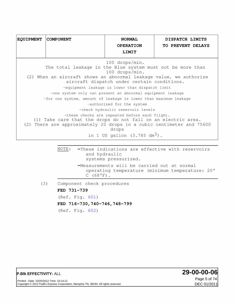
100 drops/min.The total leakage in the Blue system must not be more than
100 drops/min.(2) When an aircraft shows an abnormal leakage value, we authorize
aircraft dispatch under certain conditions.-equipment leakage is lower than dispatch limit
-one system only can present an abnormal equipment leakage
-for one system, amount of leakage is lower than maximum leakage
-authorized for the system
-check hydraulic reservoir levels
-these checks are repeated before each flight.(1) Take care that the drops do not fall on an electric area.
(2) There are approximately 20 drops in a cubic centimeter and 75600drops
in 1 US gallon (3.785 dm3).
NOTE: -These indications are effective with reservoirsand hydraulicsystems pressurized.
-Measurements will be carried out at normaloperating temperature (minimum temperature: 20°C (68°F).
(3) Component check procedures
FED 731-739
(Ref. Fig. 601)
FED 716-730,740-746,748-799
(Ref. Fig. 602)
P.Blk EFFECTIVITY: ALL 29-00-00-06Printed - Date: 10/25/2012 Time: 10:14:12Copyright © 2012 FedEx Express Corporation, Memphis TN, 38194, All rights reserved.
Page 5 of 74DEC 01/2011

(a) Functional check of leakage rate of each engine-driven pump shaft-seal drain-outlet
1) On the engine drain module/manifold, openthe hydraulic pump shaft seal drain device.
2) Measure the number of drops per minute thatare dripping out.
3) Check with the maximum permissible leakagerate table given in Para. 1.C.(2).
(b) Servo controls
1) Pressurize hydraulic system corresponding toservo controls to be checked.
2) Place flight controls in neutral position(they must not be moved from this positionthroughout the check).
3) Wait three minutes for external leakage tostabilize, then measure leakage rate (Fortolerances, ref. Para 1.C.(2).(b).).
(c) Maximum permissible leakage for hydrauliccomponents in normal operation :Slight seepage, without formation of drops, isallowed.In case of seepage, clean the component, tightenthe nuts and the bolts, and when appropriate, lookfor cracks. Monitor components daily.
(d) Maximum permissible leakage for the hydrauliclines and unions in normal operation :In case of slight seepage, retighten unions tospecified torque and wipe carefully.Pressurize relevant hydraulic system and observefaulty item.If any seepage occurs, replace union or line. Noleakage is permitted on lines and unions.
NOTE: For a whole hydraulic system, the totalexternal leakage of components shall notexceed 100 drops max. per minute.(5 CC max. per minute).
2. FED ALL
Internal Leakage Check of Each Hydraulic System by Means ofAuxiliary Power
WARNING: BEFORE PROCEEDING WITH MAINTENANCE WORK ON OR NEARMECHANICAL FLIGHT CONTROLS OR PRIMARY FLIGHT CONTROL
P.Blk EFFECTIVITY: ALL 29-00-00-06Printed - Date: 10/25/2012 Time: 10:14:12Copyright © 2012 FedEx Express Corporation, Memphis TN, 38194, All rights reserved.
Page 6 of 74DEC 01/2011

SURFACES, LANDING GEARS, ASSOCIATED DOORS OR ANY MOVINGCOMPONENT, MAKE CERTAIN THAT GROUND SAFETIES AND/ORWARNING NOTICES ARE IN CORRECT POSITION TO PREVENTINADVERTENT OPERATION OF CONTROLS.BEFORE POWER IS SUPPLIED TO THE AIRCRAFT MAKE CERTAINTHAT ELECTRICAL CIRCUITS UPON WHICH WORK IS IN PROGRESSARE ISOLATED.BEFORE PRESSURIZING HYDRAULIC SYSTEMS, MAKE CERTAIN THATHYDRAULIC SYSTEM UNDER MAINTENANCE HAS BEEN ISOLATED.
WARNING: CHECK THAT THE LANDING GEAR GROUND SAFETIES INCLUDINGWHEEL CHOCKS ARE IN POSITION.BEFORE APPLYING ON RELIEVING HYDRAULIC SYSTEM PRESSURE,MAKE CERTAIN THAT THE TRAVEL RANGES OF THE CONTROLSURFACES ARE CLEAR.BEFORE PRESSURIZING HYDRAULIC SYSTEMS, CHECK THAT ALLCONTROLS ARE SET TO CORRESPOND WITH THE ACTUAL POSITIONOF THE SERVICES THEY OPERATE.MAKE CERTAIN THAT RELEVANT CIRCUIT BREAKERS ARE OPEN,SAFETIED AND TAGGED BEFORE ATTEMPTING MAINTENANCEPROCEDURES ON ENGINE.INADVERTENT ENGINE START OR THRUST REVERSER OPERATIONCOULD RESULT IN DEATH OR SERIOUS INJURY TO PERSONNEL.
A. Reason for the JobTo monitor servo control internal leakage using Green systemelectric pumps and Green/Blue and Green/Yellow power transferunits.
NOTE: For inservice aircraft, a test performed with Greenelectric pumps enables to indicate whether the totalinternal leakage of a system is higher or lower thanthe max. permissible value.
-If the leak rate is above the max. permissible value,it is necessary to measure internal leakage persections of system with leakage measuring equipment,using isolation valves F, G and H on the systemconcerned (servo controls pushbutton switch must bereleased (out)).
-If the leak rate is below or equal to the max.permissible value, no action is necessary.
B. FED 650-651,716-746,748-799
P.Blk EFFECTIVITY: ALL 29-00-00-06Printed - Date: 10/25/2012 Time: 10:14:12Copyright © 2012 FedEx Express Corporation, Memphis TN, 38194, All rights reserved.
Page 7 of 74DEC 01/2011

Equipment and Materials
ITEM DESIGNATION
(1) C21888-0-1(2) C22783
Referenced Procedures
- (Ref. 22-10-00, P. Block 501)
- (Ref. 22-26-00, P. Block 501)
- (Ref. 22-27-00, P. Block 501)
- (Ref. 24-41-00, P. Block 301)
- (Ref. 29-21-00, P. Block 301)
- (Ref. 34-25-00, P. Block 501)
- (Ref. 27-33-00, P. Block 501)
Ground Safety Lock
Pin - Ground Safety Lock MLG
Auto Pilot Test in CMD Mode
Yaw Damper
Pitch Trim - Engage/Disengage
AC External Power Control
Green Auxiliary Power
Inertial Reference System (IRS)
Artificial Feel
FED 650-665,667-699,716-742,746,748-749POST SB 32-6040 for FED 650-651,716-742,746,748-749
B. Equipment and Materials
ITEM DESIGNATION
(1) C21888-0-2(2) C22783
Referenced Procedures
- (Ref. 22-10-00, P. Block 501)
- (Ref. 22-26-00, P. Block 501)
- (Ref. 22-27-00, P. Block 501)
- (Ref. 24-41-00, P. Block 301)
- (Ref. 29-21-00, P. Block 301)
- (Ref. 34-25-00, P. Block 501)
- (Ref. 27-33-00, P. Block 501)
Ground Safety Lock
Pin - Ground Safety Lock MLG
Auto Pilot Test in CMD Mode
Yaw Damper
Pitch Trim - Engage/Disengage
AC External Power Control
Green Auxiliary Power
Inertial Reference System (IRS)
Artificial Feel
FED 716-720
P.Blk EFFECTIVITY: ALL 29-00-00-06Printed - Date: 10/25/2012 Time: 10:14:12Copyright © 2012 FedEx Express Corporation, Memphis TN, 38194, All rights reserved.
Page 8 of 74DEC 01/2011

C. Procedure
(1) Job Set-Up
(a) Make certain that the following circuit breakersare closed:
------------------------------------------------------------------------------PANEL SERVICE IDENT. LOCATION------------------------------------------------------------------------------21VU ARTF FEEL Line 10121VU ECAM Line 10821VU SDAC and FWC2 Line 10921VU AFS/AP1 - FD1 Line 10221VU AFS/AP2 - FD2 Line 10221VU FAC1 Line 10321VU FAC2 Line 10321VU AFS/FAC1/26VAC 305CC1 103/G721VU AFS/FAC2/26VAC 305CC2 103/G821VU AFS/FAC1/28VDC 306CC1 103/G321VU AFS/FAC2/28VDC 306CC2 103/G1221VU AFS/FAC1/115VAC 309CC1 103/G521VU AFS/FAC2/115VAC 309CC2 103/G1021VU ADS/ADC2/26VAC 8FL2 105/E921VU ADS/ADC2/115VAC 9FL2 105/E1022VU MIN EQPT BAY SUPPLY/ADS/ADC1/115VC 9FL1 208/B1922VU ADS/CAPT/ALTM & VSI 24FL1 204/F18
101VU HYD/PUMP 1GE GEN1/B8101VU HYD/PUMP 2GE GEN2/B822VU LDG/GEAR/EXTEND/CTL 1GA 201/J28
133VU FLT CTL/SERVO CTL & THS/HYD/SEL 1CB 332/U63133VU FLT CTL/KRUGER 45CV 333/T61133VU FLT CTL/SLATS/26VAC/SYS1 3CV 335/R65133VU FLT CTL/SLATS/26VAC/SYS2 4CV 335/R64133VU FLT CTL/SFCC/NORM SUPPLY/SLATS/SYS1 7CV 333/T63133VU FLT CTL/SFCC/LAND RECOVERY/SUPPLY/ 9CV 335/R66
SLATS/SYS2133VU FLT CTL/SFCC/NORM SUPPLY/SLATS/SYS2 8CV 333/T64133VU HYD/ENG1 & 2/FIRE VALVES 101GK 334/S57133VU HYD/ENG1 & 2/FIRE VALVES 103GK 334/S58133VU HYD/L/G PROX DET & RELAYS SYS1/RELAYS & 2GB 332/U51
RETRACT/CTL133VU HYD/L/G PROX DET & RELAYS SYS1/FLT/GND 119GB 332/U52133VU HYD/L/G PROX DET & RELAYS SYS1/GEAR DN & 3GB 332/U53
CTR PNL/POS IND133VU HYD/L/G PROX DET & RELAYS SYS2/GEAR DOWN & 83GB 331/V51
OVHD PNL/POS IND133VU HYD/L/G PROX DET & RELAYS SYS2/FLT/GND 1GB 331/V52133VU HYD/BRAKES SYSTEM/CTL UNIT/CTL & WARN 5GG 333/T56133VU HYD/BRAKES SYSTEM/CTL UNIT/LAND RECOVERY 98GG 333/T55
/SUPPLY133VU HYD/BRAKES SYSTEM/CTL UNIT/NORM 2GG 332/U55133VU HYD/BRAKES SYSTEM/CTL UNIT/SUPPLY 41GG 332/U56133VU HYD/BRAKES SYSTEM/CTL UNIT/NORM 4GG 331/V55133VU HYD/BRAKES SYSTEM/CTL UNIT/SUPPLY 42GG 331/V56133VU HYD/AUTO BRK 95GG 335/R57------------------------------------------------------------------------------PANEL SERVICE IDENT. LOCATION------------------------------------------------------------------------------133VU HYD/RSVR/WARN 1GR 333/T58133VU HYD/ELEC/PUMPS/WARN 4GE 331/V60133VU HYD/PTU CTL/G/B 1GL 332/U59133VU HYD/PTU CTL/G/Y 6GL 332/U60
P.Blk EFFECTIVITY: ALL 29-00-00-06Printed - Date: 10/25/2012 Time: 10:14:12Copyright © 2012 FedEx Express Corporation, Memphis TN, 38194, All rights reserved.
Page 9 of 74DEC 01/2011

133VU HYD/ACCU PRESS/CTL & CARGO DOOR/PUMP 7GX 333/T51133VU HYD/RSVR/QTY/IND 1GQ 333/T59132VU LIGHTING/MAINT PANEL/ANN & MFA 1WB 324/L78
C. FED 650-665,667-699,721-746,748-799
Procedure
(1) Job Set-Up
(a) Make certain that the following circuit breakersare closed:
PANEL SERVICE IDENT. LOCATION
21VU
21VU
21VU
21VU
21VU
21VU
21VU
21VU
21VU
21VU
21VU
21VU
21VU
21VU
21VU
22VU
22VU
101VU
101VU
22VU
133VU
133VU
133VU
133VU
133VU
133VU
133VU
133VU
ARTF FEEL
ECAM
SDAC and FWC2
AFS/AP1 - FD1
AFS/AP2 - FD2
FAC1
FAC2
AFS/FAC1/26VAC
AFS/FAC2/26VAC
AFS/FAC1/28VDC
AFS/FAC2/28VDC
AFS/FAC1/115VAC
AFS/FAC2/115VAC
ADS/ADC2/26VAC
ADS/ADC2/115VAC
MIN EQPT BAY SUPPLY/ADS/ADC1/115VC
ADS/CAPT/ALTM & VSI
HYD/PUMP
HYD/PUMP
LDG/GEAR/EXTEND/CTL
FLT CTL/SERVO CTL & THS/HYD/SEL
FLT CTL/KRUGER
FLT CTL/SLATS/26VAC/SYS1
FLT CTL/SLATS/26VAC/SYS2
FLT CTL/SFCC/NORM SUPPLY/SLATS/SYS1
FLT CTL/SFCC/LAND RECOVERY/SUPPLY/
SLATS/SYS2
FLT CTL/SFCC/NORM SUPPLY/SLATS/SYS2
HYD/ENG1 & 2/FIRE VALVES
305CC1
305CC2
306CC1
306CC2
309CC1
309CC2
8FL2
9FL2
9FL1
24FL1
1GE
2GE
1GA
1CB
45CV
3CV
4CV
7CV
9CV
8CV
101GK
Line 101
Line 108
Line 109
Line 102
Line 102
Line 103
Line 103
103/G7
103/G8
103/G3
103/G12
103/G5
103/G10
105/E9
105/E10
208/B19
204/F18
GEN1/B8
GEN2/B11
201/J28
332/U63
333/T61
335/R65
335/R64
333/T63
335/R66
333/T64
334/S57
P.Blk EFFECTIVITY: ALL 29-00-00-06Printed - Date: 10/25/2012 Time: 10:14:12Copyright © 2012 FedEx Express Corporation, Memphis TN, 38194, All rights reserved.
Page 10 of 74DEC 01/2011

PANEL SERVICE IDENT. LOCATION
133VU
133VU
133VU
133VU
133VU
133VU
133VU
133VU
133VU
133VU
133VU
133VU
133VU
133VU
133VU
133VU
133VU
133VU
133VU
132VU
HYD/ENG1 & 2/FIRE VALVES
HYD/L/G PROX DET & RELAYS SYS1/RELAYS &
RETRACT/CTL
HYD/L/G PROX DET & RELAYS SYS1/FLT/GND
HYD/L/G PROX DET & RELAYS SYS1/GEAR DN &
CTR PNL/POS IND
HYD/L/G PROX DET & RELAYS SYS2/GEAR DOWN
& OVHD PNL/POS IND
HYD/L/G PROX DET & RELAYS SYS2/FLT/GND
HYD/BRAKES SYSTEM/CTL UNIT/CTL & WARN
HYD/BRAKES SYSTEM/CTL UNIT/LAND RECOVERY/
SUPPLY
HYD/BRAKES SYSTEM/CTL UNIT/NORM
HYD/BRAKES SYSTEM/CTL UNIT/SUPPLY
HYD/BRAKES SYSTEM/CTL UNIT/NORM
HYD/BRAKES SYSTEM/CTL UNIT/SUPPLY
HYD/AUTO BRK
HYD/RSVR/WARN
HYD/ELEC/PUMPS/WARN
HYD/PTU CTL/G/B
HYD/PTU CTL/G/Y
HYD/ACCU PRESS/CTL & CARGO DOOR/PUMP
HYD/RSVR/QTY/IND
LIGHTING/MAINT PANEL/ANN & MFA
103GK
2GB
119GB
3GB
83GB
1GB
5GG
98GG
2GG
41GG
4GG
42GG
95GG
1GR
4GE
1GL
6GL
7GX
1GQ
1WB
334/S58
332/U51
332/U52
332/U53
331/V51
331/V52
333/T56
333/T55
332/U55
332/U56
331/V55
331/V56
335/R57
333/T58
331/V60
332/U59
332/U60
333/T51
333/T59
324/L78
FED ALL
(b) Energize the aircraft electrical network (Ref.24-41-00, P. Block 301) . Make certain thatelectronics racks ventilation is correct.
CAUTION: DURING TEST, MAKE CERTAIN THAT NO OTHERTEST IS PERFORMED :
-ON FLIGHT CONTROLS
-ON ARTIFICIAL FEEL SYSTEM.DISPLAY WARNING NOTICES.
P.Blk EFFECTIVITY: ALL 29-00-00-06Printed - Date: 10/25/2012 Time: 10:14:12Copyright © 2012 FedEx Express Corporation, Memphis TN, 38194, All rights reserved.
Page 11 of 74DEC 01/2011
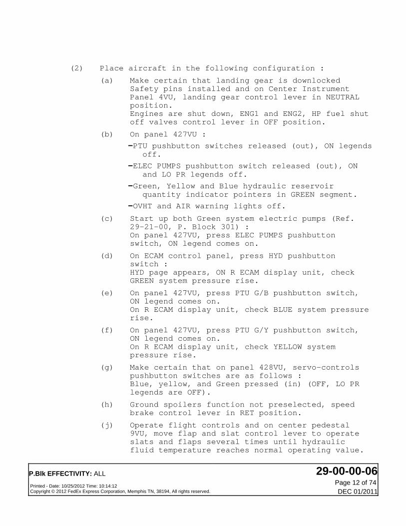
(2) Place aircraft in the following configuration :
(a) Make certain that landing gear is downlockedSafety pins installed and on Center InstrumentPanel 4VU, landing gear control lever in NEUTRALposition.Engines are shut down, ENG1 and ENG2, HP fuel shutoff valves control lever in OFF position.
(b) On panel 427VU :
-PTU pushbutton switches released (out), ON legendsoff.
-ELEC PUMPS pushbutton switch released (out), ONand LO PR legends off.
-Green, Yellow and Blue hydraulic reservoirquantity indicator pointers in GREEN segment.
-OVHT and AIR warning lights off.
(c) Start up both Green system electric pumps (Ref.29-21-00, P. Block 301) :On panel 427VU, press ELEC PUMPS pushbuttonswitch, ON legend comes on.
(d) On ECAM control panel, press HYD pushbuttonswitch :HYD page appears, ON R ECAM display unit, checkGREEN system pressure rise.
(e) On panel 427VU, press PTU G/B pushbutton switch,ON legend comes on.On R ECAM display unit, check BLUE system pressurerise.
(f) On panel 427VU, press PTU G/Y pushbutton switch,ON legend comes on.On R ECAM display unit, check YELLOW systempressure rise.
(g) Make certain that on panel 428VU, servo-controlspushbutton switches are as follows :Blue, yellow, and Green pressed (in) (OFF, LO PRlegends are OFF).
(h) Ground spoilers function not preselected, speedbrake control lever in RET position.
(j) Operate flight controls and on center pedestal9VU, move flap and slat control lever to operateslats and flaps several times until hydraulicfluid temperature reaches normal operating value.
P.Blk EFFECTIVITY: ALL 29-00-00-06Printed - Date: 10/25/2012 Time: 10:14:12Copyright © 2012 FedEx Express Corporation, Memphis TN, 38194, All rights reserved.
Page 12 of 74DEC 01/2011

Then, move the flap and slat control lever toposition 1 (0/0).
NOTE: Do not perform more than 3 consecutivecycles in order to avoid friction brakeoverheat.
(k) Align IRS 1/2/3 to prepare engagement of YAWDAMPER (Ref. 34-25-00, P. Block 501) .
(l) On PITCH FEEL section of panel 428VU, make certainthat both SYS 1 and SYS 2 pushbutton switches arepressed (in).
NOTE: This note is to point out some detailsabout YAW DAMPER 1(2) and AUTO PILOT 1(2) engagement.
-YAW DAMPER 1(2) (Ref. 22-26-00, P. Block501) para. 1.A. up to and including (3)(b) action (1)) :
-The engagement procedure calls for, in JobSet-Up paragraph, pressurization of Blueand Yellow hydraulic systems. Please donot take into account this conditionwhich is no longer necessary forelectric engagement of YAW DAMPER 1(2).
-The relevant procedure is specific toengagement of YAW DAMPER 2 however, itis also valid for YAW DAMPER 1engagement provided that for action (1)it is the YAW DAMPER 1 lever which isplaced in ON position.
-AUTO PILOT 1(2) (Ref. 22-10-00, P. Block501) A.P Test in CMD Mode para. 1.C.) :
-The engagement procedure calls for, in JobSet-Up paragraph, pressurization ofGreen and Yellow hydraulic systems.Please do not take into account thiscondition and only pressurize thehydraulic system relevant to AUTO PILOTto engage i.e Green system for AUTOPILOT 1 and Yellow system for AUTO PILOT2.
P.Blk EFFECTIVITY: ALL 29-00-00-06Printed - Date: 10/25/2012 Time: 10:14:12Copyright © 2012 FedEx Express Corporation, Memphis TN, 38194, All rights reserved.
Page 13 of 74DEC 01/2011

(3) Check of Green system
(a) On hydraulic panel 427VU, place power transferunit controls in the following configuration :
-PTU G/B pushbutton switch released (out), ONlegend OFF.
-PTU G/Y pushbutton switch released (out), ONlegend OFF.
(b) On SERVO CTL section of panel 428VU, selectpushbutton switches as follows :
-Blue and Yellow released (out).
-Green pressed (in).
(c) Engage YAW DAMPER 2 (Ref. 22-26-00, P. Block501) , Para. 1.A. up to and including (3)(b),action (1)).
(d) Engage PITCH TRIM 1 and 2 (Ref. 22-27-00, P. Block501) , Para. 1.A. up to and including (3).(b),action (1)).
(e) Engage AUTO PILOT 1 (Ref. 22-10-00, P. Block501) , A.P. test in C.M.D. mode Para. 1.C.).
NOTE: Perform engagement procedure up to andincluding the following actions of 1.C.(3).(b).1. :
-place AP1 lever in ON position
-press CWS/CMD pushbutton switch (CMDlegend comes on).
(f) To avoid PITCH TRIM control wheel movement duringleakage measurement with AUTO PILOT 1 engaged,perform the following actions :
-on glareshield panel, on FCU, pull V/S knob andselect a negative vertical speed VZ = -500 ft./mn.
The PITCH TRIM control wheel will move to nosedown direction and will stop (leave the AFS inthis condition during the entire internal leakagemeasurement).
P.Blk EFFECTIVITY: ALL 29-00-00-06Printed - Date: 10/25/2012 Time: 10:14:12Copyright © 2012 FedEx Express Corporation, Memphis TN, 38194, All rights reserved.
Page 14 of 74DEC 01/2011

(g) Open, safety and tag circuit breakers 8CV and 4CV.
(h) On center pedestal 9VU, move flap and slat controllever from position 1 (0/0) to position 2 (15/0)to extend Krueger flaps.
(j) On panel 471VU, place and hold ELEC PUMPS TESTswitch in PUMP1 or PUMP2 position (switch isspring-loaded in neutral position).
(k) On center pedestal 9VU, move back flap and slatcontrol lever from position 2 (15/0) to position 1(0/0).After 5 seconds (full retraction of Krueger flaps)and maximum 9 seconds (disengagement of Yaw AUTOPILOT), move flap and slat control lever fromposition 1 (0/0) to position 2 (15/0).
(l) During operation :
-If Green system pressure (read on ECAM displayunit) is higher than 1450 psi, permanentconsumption in Green hydraulic system is lower
than the maximum value of 20 l/mn (1220.5 in3/mn)
-If Green system pressure (read on ECAM displayunit) is lower than 1450 psi, permanentconsumption in Green hydraulic system exceeds 20
l/mn (1220.5 in3/mn).
-In this case it is necessary to locate componentswith excessive internal leakage with leakagemeasuring equipment using isolation valves F, G,H. (Ref. Para. 3. check and measurement ofhydraulic component internal leakage).
(m) Release ELEC PUMPS TEST switch.
(n) Disengage AUTO PILOT 1 (Ref. 22-10-00, P. Block501) .
(p) Disengage PITCH TRIM 1 and 2 (Ref. 22-27-00, P.Block 501) .
(q) Disengage YAW DAMPER 2 (Ref. 22-26-00, P. Block501) .
P.Blk EFFECTIVITY: ALL 29-00-00-06Printed - Date: 10/25/2012 Time: 10:14:12Copyright © 2012 FedEx Express Corporation, Memphis TN, 38194, All rights reserved.
Page 15 of 74DEC 01/2011
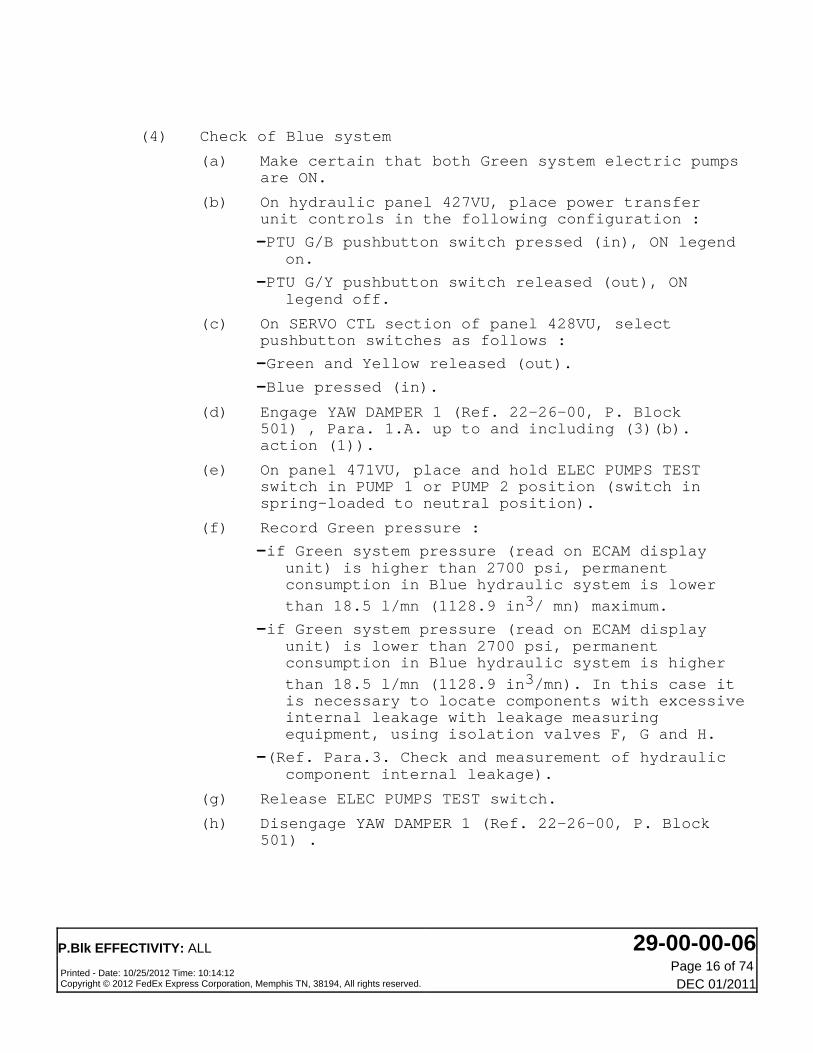
(4) Check of Blue system
(a) Make certain that both Green system electric pumpsare ON.
(b) On hydraulic panel 427VU, place power transferunit controls in the following configuration :
-PTU G/B pushbutton switch pressed (in), ON legendon.
-PTU G/Y pushbutton switch released (out), ONlegend off.
(c) On SERVO CTL section of panel 428VU, selectpushbutton switches as follows :
-Green and Yellow released (out).
-Blue pressed (in).
(d) Engage YAW DAMPER 1 (Ref. 22-26-00, P. Block501) , Para. 1.A. up to and including (3)(b).action (1)).
(e) On panel 471VU, place and hold ELEC PUMPS TESTswitch in PUMP 1 or PUMP 2 position (switch inspring-loaded to neutral position).
(f) Record Green pressure :
-if Green system pressure (read on ECAM displayunit) is higher than 2700 psi, permanentconsumption in Blue hydraulic system is lower
than 18.5 l/mn (1128.9 in3/ mn) maximum.
-if Green system pressure (read on ECAM displayunit) is lower than 2700 psi, permanentconsumption in Blue hydraulic system is higher
than 18.5 l/mn (1128.9 in3/mn). In this case itis necessary to locate components with excessiveinternal leakage with leakage measuringequipment, using isolation valves F, G and H.
-(Ref. Para.3. Check and measurement of hydrauliccomponent internal leakage).
(g) Release ELEC PUMPS TEST switch.
(h) Disengage YAW DAMPER 1 (Ref. 22-26-00, P. Block501) .
P.Blk EFFECTIVITY: ALL 29-00-00-06Printed - Date: 10/25/2012 Time: 10:14:12Copyright © 2012 FedEx Express Corporation, Memphis TN, 38194, All rights reserved.
Page 16 of 74DEC 01/2011

(5) Check of Yellow system
(a) Make certain that Green system electric pumps areON.
(b) On hydraulic panel 427VU, place power transferunit controls in the following configuration :
-PTU G/B pushbutton switch released (out), ONlegend off
-PTU G/Y pushbutton switch pressed (in), ON legendon.
(c) On SERVO CTL section of panel 428VU, selectpushbutton switches as follows :
-Green and Blue released (out).
-Yellow pressed (in).
(d) Check that flap and slat control lever is onposition 2 (15/0).
(e) Engage YAW DAMPER 2 (Ref. 22-26-00, P. Block501) , Para. 1.a. up to and including (3) (b),action (1)).
(f) Engage PITCH TRIM 1 (Ref. 22-27-00, P. Block 501) .
(g) Engage AUTOPILOT 2 :(Ref. 22-10-00, P. Block 501) - A.P Test in C.M.DMode para.1.C.).
NOTE: Perform engagement procedure up to andincluding the following action of 1.C.(3).(b).1. :
-place AP2 lever in ON position
-press CWS/CMD pushbutton switch (CMDlegend comes on).
(h) To avoid PITCH TRIM control wheel movement duringleakage measurement with AUTO PILOT 2 engaged,perform the following actions :
-on glareshield panel, on FCU, pull V/S knob andselect a negative vertical speed VZ = -500 ft./mn.
The PITCH TRIM control wheel will move to nosedown direction and will stop (leave the AFS inthis condition during the entire internal leakagemeasurement).
P.Blk EFFECTIVITY: ALL 29-00-00-06Printed - Date: 10/25/2012 Time: 10:14:12Copyright © 2012 FedEx Express Corporation, Memphis TN, 38194, All rights reserved.
Page 17 of 74DEC 01/2011

(j) On panel 471VU, place and hold ELEC PUMPS TESTswitch in PUMP1 or PUMP2 position.(Switch is spring loaded in neutral position).
(k) Record Green pressure
-if Green system pressure is higher than 2600 psi,permanent consumption in Yellow hydraulic systemis lower than the maximum value of 19 l/mn
(1159.5 in3/mn).
-If Green system pressure is lower than 2600 psi,permanent consumption in Yellow hydraulic systemis higher than the maximum value of 19 l/mn
(1159.5 in3/mn). In this case it is necessary tolocate components with excessive internalleakage with leakage measuring equipment, usingisolation valves F, G and H.
-(Ref. Para 3. Check and measurement of hydrauliccomponent internal leakage).
(l) Release ELEC PUMPS TEST switch
(m) Disengage AUTOPILOT 2 (Ref. 22-10-00, P. Block501) .
(n) Disengage PITCH TRIM 1 (Ref. 22-27-00, P. Block501) .
(p) Disengage YAW DAMPER 2 (Ref. 22-26-00, P. Block501) .
(q) On hydraulic panel 427VU release PTU G/Ypushbutton switch (ON legendOFF).
(6) Close-up
(a) In flight compartmentOn SERVO CTL section of panel 428VU, place SERVO-CONTROLS pushbutton switches in the followingconfiguration : Green, Blue and Yellow pressed(in).
P.Blk EFFECTIVITY: ALL 29-00-00-06Printed - Date: 10/25/2012 Time: 10:14:12Copyright © 2012 FedEx Express Corporation, Memphis TN, 38194, All rights reserved.
Page 18 of 74DEC 01/2011
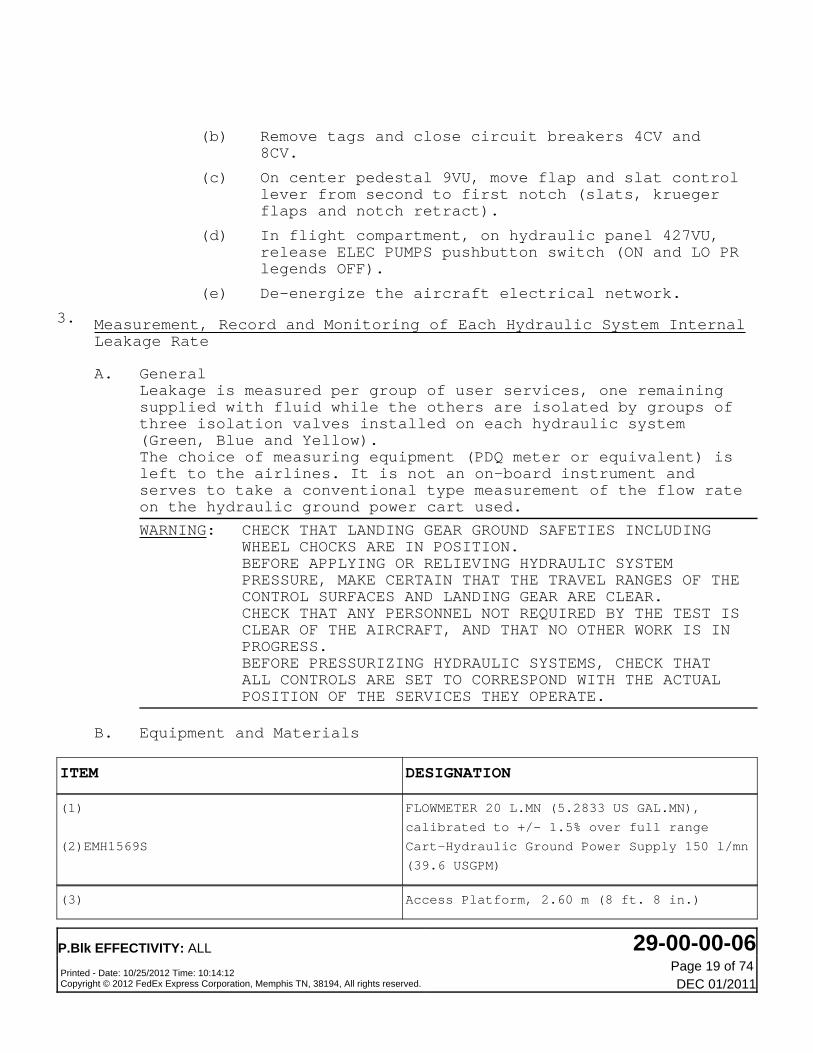
(b) Remove tags and close circuit breakers 4CV and8CV.
(c) On center pedestal 9VU, move flap and slat controllever from second to first notch (slats, kruegerflaps and notch retract).
(d) In flight compartment, on hydraulic panel 427VU,release ELEC PUMPS pushbutton switch (ON and LO PRlegends OFF).
(e) De-energize the aircraft electrical network.
3. Measurement, Record and Monitoring of Each Hydraulic System InternalLeakage Rate
A. GeneralLeakage is measured per group of user services, one remainingsupplied with fluid while the others are isolated by groups ofthree isolation valves installed on each hydraulic system(Green, Blue and Yellow).The choice of measuring equipment (PDQ meter or equivalent) isleft to the airlines. It is not an on-board instrument andserves to take a conventional type measurement of the flow rateon the hydraulic ground power cart used.
WARNING: CHECK THAT LANDING GEAR GROUND SAFETIES INCLUDINGWHEEL CHOCKS ARE IN POSITION.BEFORE APPLYING OR RELIEVING HYDRAULIC SYSTEMPRESSURE, MAKE CERTAIN THAT THE TRAVEL RANGES OF THECONTROL SURFACES AND LANDING GEAR ARE CLEAR.CHECK THAT ANY PERSONNEL NOT REQUIRED BY THE TEST ISCLEAR OF THE AIRCRAFT, AND THAT NO OTHER WORK IS INPROGRESS.BEFORE PRESSURIZING HYDRAULIC SYSTEMS, CHECK THATALL CONTROLS ARE SET TO CORRESPOND WITH THE ACTUALPOSITION OF THE SERVICES THEY OPERATE.
B. Equipment and Materials
ITEM DESIGNATION
(1)
(2)EMH1569S
FLOWMETER 20 L.MN (5.2833 US GAL.MN),
calibrated to +/- 1.5% over full range
Cart-Hydraulic Ground Power Supply 150 l/mn
(39.6 USGPM)
(3) Access Platform, 2.60 m (8 ft. 8 in.)
P.Blk EFFECTIVITY: ALL 29-00-00-06Printed - Date: 10/25/2012 Time: 10:14:12Copyright © 2012 FedEx Express Corporation, Memphis TN, 38194, All rights reserved.
Page 19 of 74DEC 01/2011

ITEM DESIGNATION
(4)97A29102035000
(5)C21888-0-1
(6)C22783
Referenced Procedures
- (Ref. 12-12-29, P. Block 001)
- (Ref. 24-41-00, P. Block 301)
- (Ref. 29-14-00, P. Block 301)
- (Ref. 32-12-11, P. Block 301)
- (Ref. 29-10-00, P. Block 301)
- (Ref. 22-10-00, P. Block 501)
- (Ref. 27-33-00, P. Block 501)
- (Ref. 22-26-00, P. Block 501)
- (Ref. 22-27-00, P. Block 501)
- (Ref. 34-25-00, P. Block 501)
Connector - Pressurizing, Hydraulic Tank
Ground Safety Lock
Pin - Ground Safety Lock MLG
Hydraulic
AC External Power Control
Hydraulic Reservoir Pressurizing System
Main Gear Main Door (Ground Door(s)Opening)
Main Hydraulic Power Pressurization/
Depressurization
Autopilot
Artificial Feel
Yaw Damper
Pitch Trim - Engage/Disengage
Inertial Reference System (IRS)
C. Procedure
(1) Job Set-Up
(a) Energize the aircraft electrical network (Ref.24-41-00, P. Block 301) . Make certain thatelectronics racks ventilation is correct.
FED ALL
(b) FED 650-651,716-746,748-799
Make certain that the following circuit breakersare closed :
PANEL SERVICE IDENT. LOCATION
(3)
(4)97A29102035000
(5)C21888-0-2
(6)C22783
Referenced Procedures
- (Ref. 12-12-29, P. Block 001)
Access Platform, 2.60 m (8 ft. 8 in.)
Connector - Pressurizing, Hydraulic Tank
Ground Safety Lock
Pin - Ground Safety Lock MLG
Hydraulic
AC External Power Control
P.Blk EFFECTIVITY: ALL 29-00-00-06Printed - Date: 10/25/2012 Time: 10:14:12Copyright © 2012 FedEx Express Corporation, Memphis TN, 38194, All rights reserved.
Page 20 of 74DEC 01/2011

PANEL SERVICE IDENT. LOCATION
- (Ref. 24-41-00, P. Block 301)
- (Ref. 29-14-00, P. Block 301)
- (Ref. 32-12-11, P. Block 301)
- (Ref. 29-10-00, P. Block 301)
- (Ref. 22-10-00, P. Block 501)
- (Ref. 27-33-00, P. Block 501)
- (Ref. 22-26-00, P. Block 501)
- (Ref. 22-27-00, P. Block 501)
- (Ref. 34-25-00, P. Block 501)
Hydraulic Reservoir Pressurizing System
Main Gear Main Door (Ground Door(s)Opening)
Main Hydraulic Power Pressurization/
Depressurization
Autopilot
Artificial Feel
Yaw Damper
Pitch Trim - Engage/Disengage
Inertial Reference System (IRS)
C. Procedure
(1) Job Set-Up
(a) Energize the aircraft electrical network (Ref.24-41-00, P. Block 301) . Make certain thatelectronics racks ventilation is correct.
FED ALL
(a) FED 650-665,667-699,716-742,746,748-749POST SB 32-6040 for FED 650-651,716-742,746,748-749
Make certain that the following circuit breakersare closed :
PANEL SERVICE IDENT. LOCATION
21VU
21VU
21VU
21VU
21VU
21VU
21VU
21VU
21VU
21VU
ARTF FEEL
ECAM
SDAC and FWC2
AFS/AP1-FD1
AFS/AP2-FD2
FAC1
FAC2
AFS/FAC1/26VAC
AFS/FAC2/26VAC
AFS/FAC1/28VDC
305CC1
305CC2
306CC1
Line 101
Line 108
Line 109
Line 102
Line 102
Line 103
Line 103
103/G7
103/G8
103/G3
P.Blk EFFECTIVITY: ALL 29-00-00-06Printed - Date: 10/25/2012 Time: 10:14:12Copyright © 2012 FedEx Express Corporation, Memphis TN, 38194, All rights reserved.
Page 21 of 74DEC 01/2011

PANEL SERVICE IDENT. LOCATION
21VU
21VU
21VU
21VU
21VU
22VU
22VU
101VU
22VU
101VU
133VU
133VU
133VU
133VU
133VU
133VU
133VU
133VU
133VU
133VU
133VU
133VU
133VU
133VU
133VU
133VU
133VU
133VU
133VU
133VU
133VU
133VU
133VU
133VU
133VU
AFS/FAC2/28VDC 306CC2
AFS/FAC1/115VAC 309CC1
AFS/FAC2/115VAC 309CC2
ADS/ADC2/26VAC 8FL2
ADS/ADC2/115VAC 9FL2
MIN EQPT BAY SUPPLY/ADS/ADC1/115VC 9FL1
ADS/CAPT/ALTM & VSI 24FL1
HYD/PUMP 1GE
LDG/GEAR/EXTEND/CTL 1GA
HYD/PUMP 2GE
FLT CTL/SERVO CTL & THS/HYD/SEL 1CB
FLT CTL/KRUGER 45CV
FLT CTL/SLATS/26VAC/SYS1 3CV
FLT CTL/SFCC/NORM SUPPLY/SLATS/SYS1 7CV
FLT CTL/SFCC/LAND RECOVERY/SUPPLY/SLATS/SYS2 9CV
FLT CTL/SFCC/NORM SUPPLY/SLATS/SYS2 8CV
FLT CTL/SLATS/26VAC/SYS2 4CV
HYD/ENG1 & 2/FIRE VALVES 101GK
HYD/ENG1 & 2/FIRE VALVES 103GK
HYD/L/G PROX DET & RELAYS SYS1/RELAYS & 2GB
RETRACT/CTL
HYD/L/G PROX DET & RELAYS SYS1/FLT/GND 119GB
HYD/L/G PROX DET & RELAYS SYS1/GEAR DN & 3GB
CTR PNL/POS IND
HYD/L/G PROX DET & RELAYS SYS2/GEAR 83GB
DOWN & OVHD PNL/POS IND
HYD/L/G PROX DET & RELAYS SYS2/FLT/GND 1GB
HYD/BRAKES SYSTEM/CTL UNIT/CTL & WARN 5GG
HYD/BRAKES SYSTEM/CTL UNIT/LAND RECOVERY/ 98GG
SUPPLY
HYD/BRAKES SYSTEM/CTL UNIT/NORM 2GG
HYD/BRAKES SYSTEM/CTL UNIT/SUPPLY 41GG
HYD/BRAKES SYSTEM/CTL UNIT/NORM 4GG
HYD/BRAKES SYSTEM/CTL UNIT/SUPPLY 42GG
HYD/AUTO BRK 95GG
HYD/RSVR/WARN 1GR
HYD/ELEC/PUMPS/WARN 4GE
HYD/PTU CTL/G/B 1GL
HYD/PTU CTL/G/Y 6GL
103/G12
103/G5
103/G10
105/E 9
105/E10
208/B19
204/F18
GEN1/B8
201/J28
GEN2/B11
332/U63
333/T61
335/R65
333/T63
335/R66
333/T64
335/R64
334/S57
334/S58
332/U51
332/U52
332/U53
331/V51
331/V52
333/T56
333/T55
332/U55
332/U56
331/V55
331/V56
335/R57
333/T58
331/V60
332/U59
332/U60
P.Blk EFFECTIVITY: ALL 29-00-00-06Printed - Date: 10/25/2012 Time: 10:14:12Copyright © 2012 FedEx Express Corporation, Memphis TN, 38194, All rights reserved.
Page 22 of 74DEC 01/2011

PANEL SERVICE IDENT. LOCATION
133VU
133VU
132VU
HYD/ACCU PRESS/CTL & CARGO DOOR/PUMP 7GX
HYD/RSVR/QTY/IND 1GQ
LIGHTING/MAINT PANEL/ANN & MFA 1WB
333/T51
333/T59
324/L78
21VU
21VU
21VU
21VU
21VU
21VU
21VU
21VU
21VU
21VU
21VU
21VU
21VU
21VU
21VU
22VU
22VU
101VU
22VU
101VU
133VU
133VU
133VU
133VU
133VU
133VU
133VU
133VU
133VU
133VU
133VU
133VU
ARTF FEEL
ECAM
SDAC and FWC2
AFS/AP1-FD1
AFS/AP2-FD2
FAC1
FAC2
AFS/FAC1/26VAC
AFS/FAC2/26VAC
AFS/FAC1/28VDC
AFS/FAC2/28VDC
AFS/FAC1/115VAC
AFS/FAC2/115VAC
ADS/ADC2/26VAC
ADS/ADC2/115VAC
MIN EQPT BAY SUPPLY/ADS/ADC1/115VC
ADS/CAPT/ALTM & VSI
HYD/PUMP
LDG/GEAR/EXTEND/CTL
HYD/PUMP
FLT CTL/SERVO CTL & THS/HYD/SEL
FLT CTL/KRUGER
FLT CTL/SLATS/26VAC/SYS1
FLT CTL/SFCC/NORM SUPPLY/SLATS/SYS1
FLT CTL/SFCC/LAND RECOVERY/SUPPLY/SLATS/
SYS2
FLT CTL/SFCC/NORM SUPPLY/SLATS/SYS2
FLT CTL/SLATS/26VAC/SYS2
HYD/ENG1 & 2/FIRE VALVES
HYD/ENG1 & 2/FIRE VALVES
HYD/L/G PROX DET & RELAYS SYS1/RELAYS&
RETRACT/CTL
HYD/L/G PROX DET & RELAYS SYS1/FLT/GND
Line 101
Line 108
Line 109
Line 102
Line 102
Line 103
Line 103
103/G7
103/G8
103/G3
103/G12
103/G5
103/G10
105/E 9
105/E10
208/B19
204/F18
GEN1/B8
201/J28
GEN2/B11
332/U63
333/T61
335/R65
333/T63
335/R66
333/T64
335/R64
334/S57
334/S58
332/U51
332/U52
332/U53
305CC1
305CC2
306CC1
306CC2
309CC1
309CC2
8FL2
9FL2
9FL1
24FL1
1GE
1GA
2GE
1CB
45CV
3CV
7CV
9CV
8CV
4CV
101GK
103GK
2GB
119GB
3GB
83GB
1GB
5GG
P.Blk EFFECTIVITY: ALL 29-00-00-06Printed - Date: 10/25/2012 Time: 10:14:12Copyright © 2012 FedEx Express Corporation, Memphis TN, 38194, All rights reserved.
Page 23 of 74DEC 01/2011

PANEL SERVICE IDENT. LOCATION
133VU
133VU
133VU
133VU
133VU
133VU
133VU
133VU
133VU
133VU
133VU
133VU
133VU
133VU
133VU
132VU
HYD/L/G PROX DET & RELAYS SYS1/GEARDN &
CTR PNL/POS IND
HYD/L/G PROX DET & RELAYS SYS2/GEAR
DOWN & OVHD PNL/POS IND
HYD/L/G PROX DET & RELAYS SYS2/FLT/GND
HYD/BRAKES SYSTEM/CTL UNIT/ CTL & WARN
HYD/BRAKES SYSTEM/CTL UNIT/LANDRECOVERY/
SUPPLY
HYD/BRAKES SYSTEM/CTL UNIT/NORM
HYD/BRAKES SYSTEM/CTL UNIT/SUPPLY
HYD/BRAKES SYSTEM/CTL UNIT/NORM
HYD/BRAKES SYSTEM/CTL UNIT/SUPPLY
HYD/AUTO BRK
HYD/RSVR/WARN
HYD/ELEC/PUMPS/WARN
HYD/PTU CTL/G/B
HYD/PTU CTL/G/Y
HYD/ACCU PRESS/CTL & CARGO DOOR/PUMP
HYD/RSVR/QTY/IND
LIGHTING/MAINT PANEL/ANN & MFA
331/V51
331/V52
333/T56
333/T55
332/U55
332/U56
331/V55
331/V56
335/R57
333/T58
331/V60
332/U59
332/U60
333/T51
333/T59
324/L78
98GG
2GG
41GG
4GG
42GG
95GG
1GR
4GE
1GL
6GL
7GX
1GQ
1WB
FED ALL
(b) Make certain that aircraft is in the followingconfiguration:
-Aircraft on wheels and safety pins installed.
-Landing gear normal control lever in NEUTRALposition.
(c) Open left main landing gear door (Ref. 32-12-11,P. Block 301) .
WARNING: WHEN DOOR IS OPEN MAKE CERTAIN THATSAFETY COLLAR IS POSITIONED ON DOORACTUATING CYLINDER.
(d) Make certain that hydraulic reservoirs arepressurized to 3.5 bars (50 psi) ; pressurize ifrequired (Ref. 29-14-00, P. Block 301) .
P.Blk EFFECTIVITY: ALL 29-00-00-06Printed - Date: 10/25/2012 Time: 10:14:12Copyright © 2012 FedEx Express Corporation, Memphis TN, 38194, All rights reserved.
Page 24 of 74DEC 01/2011

(e) Check that fluid in the three hydraulic reservoirsis at correct fill level. Top up if required (Ref.12-12-29, P. Block 001) .
(f) Connect hydraulic ground power cart, equipped withmeasuring equipment (flowmeter), to system to betested. Temperature of fluid during measurementprocedures must be higher than 20°C (68°F).Pressurize system until pressure and temperaturestabilize (check on ground power cartinstruments).
D. Leakage Measurement Procedure
NOTE: A flow rate of 50 l/mn (13.2 USGPM) is sufficient toperform the test.
(1) Pressurize system to be tested to 3000 psi (206 bars).(Ref. 29-10-00, P. Block 301) .
(2) Measure the maximum permissible leakage rate (M.P.L.R.)for Q1, Q2, Q3, Q4 and Q5 with respect to the following :
NOTE: System and component maximum permissibleleakage rates are established as the limitbeyond which system or component performanceis degraded to an unacceptable level.Nominal flow rates Q2, Q3, Q4 and Q5 areindicative of a subsection condition.
(a) Perform all measurements from flow rates Q1 to Q5to properly determine subsection leakage.
NOTE: Validity of results can be cross-checkedusing the following equation providedthat Q1 is measured with YAW DAMPER and/or PITCH FEEL engaged :Q1 (left or right) ± 10 % = Q3 + Q4 + Q5- 2Q2.
1) If Q1 flow rate is BELOW OR EQUAL to theMaximum Permissible Leakage Rate, no actionis necessary.
2) If Q1 flow rate EXCEEDS the MaximumPermissible Leakage Rate, do the following :
NOTE: As Q1 flow rate is out of thesystem M.P.L.R., the subsectionM.P.L.R. for Q2 to Q5 is thenominal flow rate which value is
P.Blk EFFECTIVITY: ALL 29-00-00-06Printed - Date: 10/25/2012 Time: 10:14:12Copyright © 2012 FedEx Express Corporation, Memphis TN, 38194, All rights reserved.
Page 25 of 74DEC 01/2011
given for each system in theleakage measurement paragraphs.
-If one or several measured flowrates Q2, Q3, Q4, Q5 is out of theM.P.L.R, replace the faultycomponent per para. (3).
-If one or several measured flowrates Q2, Q3, Q4, Q5 is out of theM.P.L.R., and that the componentsof the involved subsection arewithin their internal leakagelimit, remove and replace one ormore components to restoresubsection and system leakage rateto permissible limits.
(b) To avoid PITCH TRIM control wheel movement duringmeasurement leakage with AUTO PILOT 1(2) engagedafter engagement of AUTO PILOT 1(2) perform thefollowing actions :
-On glareshield panel, on FCU, pull V/S knob andselect a negative vertical speed VZ = -500 ft./mn.
NOTE: This note is to point out some detailsabout YAW DAMPER 1(2) and AUTO PILOT 1(2) engagement.
-YAW DAMPER 1(2) (Ref. 22-26-00, P. Block501) para. 1.A. up to and including (3)(b) action (1)) :
-The engagement procedure calls for, in JobSet-Up paragraph, pressurization of Blueand Yellow hydraulic systems. Please donot take into account this conditionwhich is no longer necessary forelectric engagement of YAW DAMPER 1(2).
-The relevant procedure is specific toengagement of YAW DAMPER 2 however, itis also valid for YAW DAMPER 1engagement provided that for action (1)it is the YAW DAMPER 1 lever which isplaced in ON position.
-AUTO PILOT 1(2) (Ref. 22-10-00, P. Block501) A.P Test in CMD Mode para. 1.C.) :
P.Blk EFFECTIVITY: ALL 29-00-00-06Printed - Date: 10/25/2012 Time: 10:14:12Copyright © 2012 FedEx Express Corporation, Memphis TN, 38194, All rights reserved.
Page 26 of 74DEC 01/2011

-The engagement procedure calls for, in JobSet-Up paragraph, pressurization ofGreen and Yellow hydraulic system.Please do not take into account thiscondition and only pressurize thehydraulic system relevant to AUTO PILOTto engage i.e Green system for AUTOPILOT 1 and Yellow system for AUTO PILOT2.
(3) If permanent consumption exceeds permissible limit,isolate the faulty component by :
-isolating section of system
-checking aurally
-checking local temperature variations.
CAUTION: TO AVOID COMPONENT DAMAGE IN CASE SUPPLYPRESSURE IS APPLIEDDO NOT BLANK SERVO CONTROL RETURN OPENING.
A method of confirming that a servo control is faulty isto repeat the measurement procedure with the hydrauliclines to the suspect servo control disconnected andcapped.If a normal leakage rate is then recorded, this confirmsthat the suspect servo control is faulty.
E. Green System Testing(Ref. Fig. 603)
NOTE: On Green system isolation valves :Letter F is associated with Left Wing.Letter G is associated with Tail Unit.Letter H is associated with Right Wing.
(1) Job Set-Up
(a) Check that green system pressure is 3000 psi (206bars), then shut down hydraulic ground power cart.
(b) Check pumps delivery relief valve 291063 to detectpossible jamming of valve in open position, eitheraurally or by feel (vibrations).
(c) Pressurize system again to 3000 psi (206 bars).
(2) Leakage rate check
(a) For each position of isolation valves, performactions shown on following chart and compare
P.Blk EFFECTIVITY: ALL 29-00-00-06Printed - Date: 10/25/2012 Time: 10:14:12Copyright © 2012 FedEx Express Corporation, Memphis TN, 38194, All rights reserved.
Page 27 of 74DEC 01/2011

leakage rate recorded with correspondingpermissible leakage rate.
NOTE: In each configuration, wait for pressureand leakage to stabilize before takingmeasurements with flowmeter.
(b) On PITCH FEEL section of panel 428VU, make certainthat SYS 1 pusbutton switch is pressed (in).
NOTE: Align IRS 1/2/3 to prepare engagement ofYAW DAMPER 1 (Ref. 34-25-00, P. Block501) .
MAXIMUM PERMISSIBLE LEAKAGE RATE - GREEN SYSTEM :
20 l/mn (1220.5 in3/mn) (Left or Right) If theMaximum Permissible Leakage Rate is above 20 l/mn,check subsections to find the cause.If the Maximum Permissible Leakage Rate is belowor equal to 20 l/mn, no action is necessary.
(c) Flow rate Q1
1) In flight compartment : on panel 428VU, makecertain that Green servo controls pushbuttonswitch is pressed (in).
2) In hydraulics compartment, place Greensystem isolation valves in the followingconfiguration : F, G, H closed.
NOTE: Measurements must be taken withaileron control wheel turned fullleft or full right.
-------------------------------------------------------------------------------COMPONENTS MAX PERMISSIBLE LIMIT-------------------------------------------------------------------------------2 All speed aileron (ASA) servo controls 4 l/mn (244 in3/mn)2 Elevator servo controls 5 l/mn (305 in3/mn)1 Rudder servo control 2.5 l/mn (153 in3/mn)2 Spoiler servo controls 2 l/mn (122 in3/mn)1 Trimmable horizontal stabilizer (THS) 1.5 l/mn (92 in3/mn)actuator motor
1 Slat power control unit motor 0.22 l/mn (13.4 in3/mn)1 Flap power control unit motor 0.22 l/mn (13.4 in3/mn)Miscellaneous (Yaw AP, Roll AP, Pitch 4 l/mn (244 in3/mn)AP, Pitch Feel).2 Power transfer unit (PTU) 0.3 l/mn (18.3 in3/mn)1 Landing gear selector valve 0.08 l/mn (4.9 in3/mn)1 Brake selector valve 0.17 l/mn (10.4 in3/mn)1 Landing gear free fall cutout valve 0.07 l/mn (4.3 in3/mn)
3) Leakage Measurement with PITCH TRIM 1 and 2,AUTO PILOT 1 and PITCH FEEL SYS 1 Engaged
NOTE: On leakage measurement diagram,the shaded areas represent
P.Blk EFFECTIVITY: ALL 29-00-00-06Printed - Date: 10/25/2012 Time: 10:14:12Copyright © 2012 FedEx Express Corporation, Memphis TN, 38194, All rights reserved.
Page 28 of 74DEC 01/2011
components on which internalleakage is measured according toservo controls selector valve andisolation valves position.
(Ref. Fig. 604)
-On overhead panel on PITCH FEEL section ofpanel 428VU, make certain that PITCH FEELSYS 1 (Ref. 27-33-00, P. Block 501) isstill engaged.
-Engage PITCH TRIM 1 and 2 (Ref. 22-27-00, P.Block 501) , Para. 1.A. up to andincluding (3)(b), action (1)).
-Engage Yaw DAMPER 1 (Ref. 22-26-00, P. Block501) , Para. 1.A. up to and including (3)(b), action (1)).
-Engage AUTO PILOT 1 (Ref. 22-10-00, P. Block501) , A.P. test in
-C.M.D. Mode Para. 1.C.)
NOTE: Perform engagement procedure up toand including the following actionof 1.C.(3).(b).1. :
-Place AP1 lever in On position
-Press CWS/CMD pushbutton switch (CMDlegend comes on)
-Measure leakage.
NOTE: The MPLR of the Green system is 20
l/mn (1220.5 in3/mn).
-Disengage PITCH TRIM 1 and 2 (Ref. 22-27-00,P. Block 501) .
-Disengage YAW DAMPER 1 (Ref. 22-26-00, P.Block 501) .
-On glareshield on FCU, disengage AUTO PILOT1 (Ref. 22-10-00, P. Block 501) .
4) Leakage measurement with PITCH FEEL SYS 1engaged and AUTO PILOT 1 disengaged.
NOTE: The purpose of this leakagemeasurement (AUTO PILOT 1disengaged) is only to allow AUTOPILOT LEAKAGE RATE determination
P.Blk EFFECTIVITY: ALL 29-00-00-06Printed - Date: 10/25/2012 Time: 10:14:12Copyright © 2012 FedEx Express Corporation, Memphis TN, 38194, All rights reserved.
Page 29 of 74DEC 01/2011

by comparison between the flowrate value recorded in Para. 3.and the one measured in thisparagraph.
-On overhead panel on PITCH FEEL section ofpanel 428VU, make certain that PITCH FEELSYS 1 (Ref. 27-33-00, P. Block 501) isstill engaged.
-open, safety and tag following circuitbreaker :
PANEL SERVICE IDENT. LOCATION
21VU AFS/AP1-FD1/FCC1/28VDC 306CA1 102/H3
-measure leakage.
NOTE: If the difference between the flowrate value recorded in Para. 3.and the one measured in this Para.
exceeds 3 l/mn (183 in3/mn), it isnecessary to check AUTO PILOT forexcessive internal leakage.
-Restore system to normal operatingcondition.
(d) Flow rate Q2(Ref. Fig. 605)
NOTE: On leakage measurement diagram, theshaded areas represent components onwhich internal leakage is measuredaccording to servo controls selectorvalve and isolation valves position.
1) In flight compartment : on panel 428VU,release Green servo controls pushbuttonswitch.
2) In hydraulics compartment, make certain thatGreen system isolation valves are in thefollowing configuration : F, G, H closed.
NOTE: Measured flow rate is the leakagerate of components locateddownstream of HP manifold.
P.Blk EFFECTIVITY: ALL 29-00-00-06Printed - Date: 10/25/2012 Time: 10:14:12Copyright © 2012 FedEx Express Corporation, Memphis TN, 38194, All rights reserved.
Page 30 of 74DEC 01/2011

-------------------------------------------------------------------------------COMPONENTS MAX PERMISSIBLE LIMIT-------------------------------------------------------------------------------1 Flap power control unit 0.22 l/mn (13.4 in3/mn)1 Slat power control unit 0.22 l/mn (13.4 in3/mn)2 Power transfer unit (PTU) 0.3 l/mn (18.3 in3/mn)1 Landing gear selector valve 0.08 l/mn (4.9 in3/mn)1 Brake selector valve 0.17 l/mn (10.4 in3mn)
3) Measure leakage
NOTE: -If Q1 value is below or equal to theMPLR of the system, i.e. 20 l/mn(1220.5 in./mn) the MPLR of the
subsection is 2 l/mn (121 in3/mn).
-If Q1 value exceeds the MPLR ofsystem i.e. 20 l/mn (1220.5 in3/mn), the MPLR of subsection Q2 is
1 l/mn (61.00 in3/mn).
-In both cases, if flow rate Q2exceeds the relevant MPLR,identify the faulty componentusing method described in Para.3.D.(3).If listed components are withintheir max. Permissible limit,check the other hydrauliccomponents not isolated during theleakage measurement of Q2subsection.If listed components are withintheir max. Permissible limit,check the other hydrauliccomponents not isolated during theleakage measurement of Q2subsection.
4) Restore system to normal operatingcondition.
(e) Flow rate Q3(Ref. Fig. 606)
NOTE: On leakage measurement diagram, theshaded areas represent components onwhich internal leakage is measuredaccording to servo controls selectorvalve and isolation valves position.
P.Blk EFFECTIVITY: ALL 29-00-00-06Printed - Date: 10/25/2012 Time: 10:14:12Copyright © 2012 FedEx Express Corporation, Memphis TN, 38194, All rights reserved.
Page 31 of 74DEC 01/2011

1) In flight compartment : on panel 428VU, makecertain that Green servo controls pushbuttonswitch is released (out).
2) In hydraulics compartment, place Greensystem isolation valves in the followingconfiguration : G open and F, H closed.
3) On overhead panel, on PITCH FEEL section ofpanel 428VU, make certain that PITCH FEELSYS 1 (Ref. 27-33-00, P. Block 501) is stillengaged.
NOTE: Measured flow rate is the leakagerate of components located in tailcone and downstream of HPmanifold.
-------------------------------------------------------------------------------COMPONENTS MAX PERMISSIBLE LIMIT-------------------------------------------------------------------------------2 Elevator servo controls 5 l/mn (305 in3/mn)1 Rudder servo control 2.5 l/mn (153 in3/mn)1 THS actuator motor 1.5 l/mn (92 in3/mn)1 slat power control unit motor 0.22 l/mn (13.4 in3/mn)1 flap power control unit motor 0.22 l/mn (13.4 in3/mn)Miscellaneous (Pitch Feel) 1 l/mn (61 in3/mn)2 Power transfer unit (PTU) 0.3 l/mn (18.3 in3/mn)1 Landing gear selector valve 0.08 l/mn (4.9 in3/mn)1 Brake selector valve 0.17 l/mn (10.4 in3/mn)1 Landing gear free fall cutout valve 0.07 l/mn (4.3 in3/mn)
4) Measure leakage
NOTE: The M.P.L.R. of subsection Q3 is :
10 l/mn (610 in3/mn) + Q2.If the M.P.L.R. of subsection Q3 isexceeded, facilitate identification of thefaulty component using method described inPara. 3.D.(3).
5) Restore system to normal operatingcondition.
(f) Flow rate Q4(Ref. Fig. 607)
NOTE: On leakage measurement diagram, theshaded areas represent components onwhich internal leakage is measuredaccording to servo controls selectorvalve and isolation valves position.
P.Blk EFFECTIVITY: ALL 29-00-00-06Printed - Date: 10/25/2012 Time: 10:14:12Copyright © 2012 FedEx Express Corporation, Memphis TN, 38194, All rights reserved.
Page 32 of 74DEC 01/2011

1) On overhead panel, on panel 428VU makecertain that Green servocontrols pushbuttonswitch is released (out).
2) In hydraulics compartment, place Greensystem isolation valves in the followingconfiguration : F open, G, H closed.
3) Make certain that aileron control wheel isin full left position.
NOTE: Measured flow rate is the leakagerate of components located in leftwing and downstream of HPmanifold.
-------------------------------------------------------------------------------COMPONENTS MAX. PERMISSIBLE LIMIT-------------------------------------------------------------------------------1 All speed aileron servo control 2 l/mn (122 in3/mn)1 Spoiler servo control 1 l/mn (61 in3/mn)1 slat power control unit motor 0.22 l/mn (13.4 in3/mn)1 Flap power control unit motor 0.22 l/mn (13.4 in3/mn)2 Power transfer unit (PTU) 0.3 l/mn (18.3 in3/mn)1 Landing gear selector valve 0.08 l/mn (4.9 in3/mn)1 Brake selector valve 0.17 l/mn (10.4 in3/mn)1 Landing gear free fall cutout valve 0.07 l/mn (4.3 in3/mn)
4) Measure leakage
NOTE: The M.P.L.R. of subsection Q4 is 3
l/mn (183 in3/mn) + Q2.If the M.P.L.R. of subsection Q4 isexceeded, facilitate identification of thefaulty component using method described inPara. 3.D.(3).
5) Restore system to normal operatingcondition.
(g) Flow Rate Q5(Ref. Fig. 608)
NOTE: On leakage measurement diagram, theshaded areas represent components onwhich internal leakage is measuredaccording to servo controls selectorvalve and isolation valves position.
P.Blk EFFECTIVITY: ALL 29-00-00-06Printed - Date: 10/25/2012 Time: 10:14:12Copyright © 2012 FedEx Express Corporation, Memphis TN, 38194, All rights reserved.
Page 33 of 74DEC 01/2011

1) On overhead panel, on panel 428VU, makecertain that Green servo controls pushbuttonswitch is released (out).
2) In hydraulics compartment, place Greensystem isolation valves in the followingconfiguration : H open, G, F, closed.
3) Make certain that aileron control wheel isin full right position.
NOTE: -Measured flow rate is the leakagerate of components located inright wing and downstream of HPmanifold.
-------------------------------------------------------------------------------COMPONENTS MAX. PERMISSIBLE LIMIT-------------------------------------------------------------------------------1 All speed aileron servo control 2 l/mn (122 in3/mn)1 spoiler servo control 1 l/mn (61 in3/mn)2 Power transfer unit (PTU) 0.3 l/mn (18.3 in3/mn)1 Landing gear selector valve 0.08 l/mn (4.9 in3/mn)1 Brake selector valve 0.17 l/mn (10.4 in3/mn)1 Slat power control unit motor 0.22 l/mn (13.4 in3/mn)1 Flap power control unit motor 0.22 l/mn (13.4 in3/mn)1 Landing gear free fall cutout valve 0.07 l/mn (4.3 in3/mn)
4) Measure leakage
NOTE: The M.P.L.R. of subsection Q5 is 3
l/mn (183 in3/mn) + Q2.In the M.P.L.R. of subsection Q5 isexceeded, facilitate identification of thefaulty component using method described inPara. 3.D.(3).
5) Restore system to normal operatingcondition.
(3) Green system flow rate measurement close-up :
(a) In hydraulics compartment, close the three Greensystem isolation valves.
(b) In flight compartment, on panel 428VU, press Greenservo controls pushbutton switch.
(c) Remove safety clip and tag and close circuitbreaker : 306CA1.
(d) With Green hydraulic system pressurized,successively operate the following controls :
-elevator
-rudder
P.Blk EFFECTIVITY: ALL 29-00-00-06Printed - Date: 10/25/2012 Time: 10:14:12Copyright © 2012 FedEx Express Corporation, Memphis TN, 38194, All rights reserved.
Page 34 of 74DEC 01/2011

-aileronExtend then retract flaps and slats.Make certain that components considered deflectand operate normally.
F. Blue System Testing(Ref. Fig. 609)
NOTE: On blue System isolation valves :Letter F is associated with Right Wing Letter G isassociated with Left Wing Letter H is associated withTail Unit
(1) Job Set-Up
(a) Check that Blue system pressure is 3000 psi (206bars) then shut down hydraulic ground power cart.
(b) Check pump delivery relief valve 292063 forinternal leakage, either aurally or by feel(vibrations).
(c) Pressurize system again to 3000 psi (206 bars).(Ref. 29-10-00, P. Block 301) .
(2) Leakage rate check
(a) For each position of isolation valves, performactions shown on following chart and compareleakage rate recorded with correspondingpermissible leakage rate.
NOTE: In each configuration, wait for pressureand flow to stabilize before takingmeasurements with flowmeter.
(b) On overhead panelEngage YAW DAMPER 1 (Ref. 22-26-00, P. Block501) , Para. 1.A. up to and including (3)(b),action (1)).MAXIMUM PERMISSIBLE LEAKAGE RATE-BLUE SYSTEM :
18.5 l/mn (1128.9 in.3/mn (Left or Right).
-If the Maximum Permissible Leakage Rate is above18.5 l/mn, check subsections to find the cause.
-If the Maximum Permissible Leakage Rate is belowor equal to 18.5 l/mn, no action is necessary.
(c) Flow rate Q1(Ref. Fig. 610)
NOTE: On leakage measurement diagram, theshaded areas represent components on
P.Blk EFFECTIVITY: ALL 29-00-00-06Printed - Date: 10/25/2012 Time: 10:14:12Copyright © 2012 FedEx Express Corporation, Memphis TN, 38194, All rights reserved.
Page 35 of 74DEC 01/2011

which internal leakage is measuredaccording to servo controls selectorvalve and isolation valves position.
1) In flight compartment, on panel 428VU, makecertain that Blue servo controls pushbuttonswitch is pressed (in).
2) In hydraulics compartment, place Blue systemisolation valves in the followingconfiguration : F, G, H, closed.
NOTE: measurements must be taken withaileron control wheel in full leftor full right position.
-------------------------------------------------------------------------------COMPONENTS MAX. PERMISSIBLE LIMIT-------------------------------------------------------------------------------2 All speed aileron servo controls 4 l/mn (244 in3/mn)2 elevator servo controls 5 l/mn (305 in3/mn)1 rudder servo control 2.5 l/mn (153 in3/mn)1 slat power control unit motor 0.22 l/mn (13.4 in3/mn)6 spoiler servo controls 6 l/mn (356 in3/mn)Miscellaneous (Yaw Damper) 1 l/mn (61 in3/mn)
3) Measure leakage
NOTE: The M.P.L.R of the Blue system is
18.5 l/mn (1128.9 in3/mn).
(d) Flow rate Q2(Ref. Fig. 611)
NOTE: On leakage measurement diagram, theshaded areas represent components onwhich internal leakage is measuredaccording to servo controls selectorvalve and isolation valves position.
1) In flight compartment, on panel 428VU,release Blue servo controls pushbuttonswitch.
2) In hydraulics compartment, make certain thatBlue system isolation valves are in thefollowing configuration : F, G, H closed.
NOTE: measured flow rate is the leakagerate of components locateddownstream of HP manifold.
-------------------------------------------------------------------------------COMPONENTS MAX. PERMISSIBLE LIMIT-------------------------------------------------------------------------------1 slat power control unit motor 0.22 l/mn (13.4 in3/mn)
P.Blk EFFECTIVITY: ALL 29-00-00-06Printed - Date: 10/25/2012 Time: 10:14:12Copyright © 2012 FedEx Express Corporation, Memphis TN, 38194, All rights reserved.
Page 36 of 74DEC 01/2011

3) Measure leakage
NOTE: The M.P.L.R. of subsection Q2 is
0.25 l/mn (15.3 in3/mn).If the M.P.L.R. of subsection Q2is exceeded facilitateidentification of the faultycomponent using method describedin Para.3.D.(3).If slat P.C.U. is within its max.permissible limit check the otherhydraulic components not isolatedduring the leakage measurement ofQ2 subsection and for whichinternal leakage were consideredas negligible.
4) Restore system to normal operating condition
(e) Flow rate Q3(Ref. Fig. 612)
NOTE: On leakage measurement diagram, theshaded areas represent components onwhich internal leakage is measuredaccording to servo controls selectorvalve and isolation valves position.
1) In flight compartment, on panel 428VU, makecertain that Blue servo controls pushbuttonswitch is released (out).
2) Make certain that YAW DAMPER 1 is stillengaged (Ref. 22-26-00, P. Block 501) Para.1.A. up to and including (3) (b) action (1)).
3) In hydraulics compartment, place Blue systemisolation valves in the followingconfiguration :H open and F, G closed.
NOTE: measured flow rate is the leakagerate of components located in tailunit and downstream of HPmanifold.
-------------------------------------------------------------------------------COMPONENTS MAX. PERMISSIBLE LIMIT-------------------------------------------------------------------------------2 Elevator servo controls 5 l/mn (305 in3/mn)1 Rudder servo control 2.5 l/mn (153 in3/mn)1 Slat control unit motor 0.22 l/mn (13.4 in3/mn)Miscellaneous (Yaw Damper) 1 l/mn (61 in3/mn)
P.Blk EFFECTIVITY: ALL 29-00-00-06Printed - Date: 10/25/2012 Time: 10:14:12Copyright © 2012 FedEx Express Corporation, Memphis TN, 38194, All rights reserved.
Page 37 of 74DEC 01/2011

4) Measure leakage
NOTE: -If Q1 value is below or equal to theM.P.L.R. of system i.e 18.5 l/mn
(1128.9 in3/mn), the M.P.L.R. ofsubsection Q3 is 8.25 l/mn (503.2
in3/mn) + Q2.
-If Q1 value exceeds the M.P.L.R. ofsystem i.e 18.5 l/mn (1128.9 in3/mn), the M.P.L.R. of subsection Q3
is 7.5 l/mn (457.5 in3/mn) + Q2.
-In both cases, if nominal flow rateQ3 exceeds the relevant
-M.P.L.R., identify the faultycomponent using method describedPara. 3.D.(3).
5) Restore system to normal operatingcondition.
-Disengage YAW DAMPER 1 (Ref. 22-26-00, P.Block 501) .
(f) Flow rate Q4(Ref. Fig. 613)
NOTE: On leakage measurement diagram theshaded areas represent components onwhich internal leakage is measuredaccording to servo controls selectorvalve and isolation valves postion.
1) On overhead panel, on panel 428VU, makecertain that Blue servo controls pushbuttonswitch is released (out).
2) In hydraulics compartment, place Blue systemisolation valves in the followingconfiguration : G open F, H closed.
3) Make certain that aileron control wheel isin full left position.
NOTE: Measured flow rate is the leakagerate of components located in leftwing and downstream of HPmanifold.
-------------------------------------------------------------------------------COMPONENTS MAX. PERMISSIBLE LIMIT-------------------------------------------------------------------------------
P.Blk EFFECTIVITY: ALL 29-00-00-06Printed - Date: 10/25/2012 Time: 10:14:12Copyright © 2012 FedEx Express Corporation, Memphis TN, 38194, All rights reserved.
Page 38 of 74DEC 01/2011

1 All speed aileron servo control 2 l/mn (122 in3m/mn)3 spoiler servo controls 3 l/mn (183 in3/mn)1 slat power control unit motor 0.22 l/mn (13.4 in3/mn)
4) Measure leakage
NOTE: The M.P.L.R. of subsecion Q4 is 5l/
mn (305 in3/mn) + Q2.If the M.P.L.R. of subsection Q4 isexceeded, facilitate identification of thefaulty component using method described inPara. 3.D.(3).
5) Restore system to normal operatingcondition.
(g) Flow rate Q5(Ref. Fig. 614)
NOTE: On leakage measurement diagram, theshaded areas represent components onwhich internal leakage is measuredaccording to servo controls selectorvalve and isolation valves position.
1) On overhead panel, on panel 428VU, makecertain that Blue servo controls pushbuttonswitch is released (out).
2) In hydraulics compartment, place Blue systemisolation valves in the followingconfiguration : F open G, H closed.
3) Make certain that aileron control wheel isin full right position.
NOTE: Measured flow rate is the leakagerate of components located inright wing and downstream of HPmanifold.
-------------------------------------------------------------------------------COMPONENTS MAX. PERMISSIBLE LIMIT-------------------------------------------------------------------------------1 All speed aileron servo control 2 l/mn (122 in3/mn)3 spoiler servo controls 3 l/mn (183 in3/mn)1 slat power control unit motor 0.22 l/mn (13.4 in3/mn)
4) Measure leakage
NOTE: The M.P.L.R. of subsection Q5 is 5
l/mn (305 in3/mn) + Q2.If the M.P.L.R. of subsection Q5 isexceeded, facilite identification of the
P.Blk EFFECTIVITY: ALL 29-00-00-06Printed - Date: 10/25/2012 Time: 10:14:12Copyright © 2012 FedEx Express Corporation, Memphis TN, 38194, All rights reserved.
Page 39 of 74DEC 01/2011

faulty component using method described inPara. 3.D.(3).
5) Restore system to normal operatingcondition.
(3) Blue system flow rate measurement close-up
(a) In hydraulics compartment, close the three Bluesystem isolation valves.
(b) In flight compartment, on panel 428VU, press Blueservo controls pushbutton switch.
(c) With Blue system pressurized, successively operatethe following controls :
-elevator
-rudder
-aileronExtend then retract slatsMake certain that components considered deflectand operate normally.
G. Yellow System Testing(Ref. Fig. 615)
NOTE: On Yellow system isolation valves :Letter F is associated with Left Wing Letter G isassociated with Tail Unit Letter H is associated withRight Wing
(1) Job Set-Up
(a) Check that Yellow system pressure is 3000 psi (206bars) then shut down hydraulic ground power cart.
(b) Check pump delivery relief valve 293063 and 293067for internal leakage, either aurally, or by feel(vibrations).
(c) Pressurize Yellow system again to 3000 psi (206bars). (Ref. 29-10-00, P. Block 301) .
(2) Leakage rate check
NOTE: Compared with Green and Blue hydraulic system,the nominal internal flow rates for yellowsubsections (Q3, Q4, Q5) are more restrictivein order to take into account Ram Air Turbineutilization which is an ultimate emergencyhydraulic power with flow capacity of only 45l/mn.
P.Blk EFFECTIVITY: ALL 29-00-00-06Printed - Date: 10/25/2012 Time: 10:14:12Copyright © 2012 FedEx Express Corporation, Memphis TN, 38194, All rights reserved.
Page 40 of 74DEC 01/2011
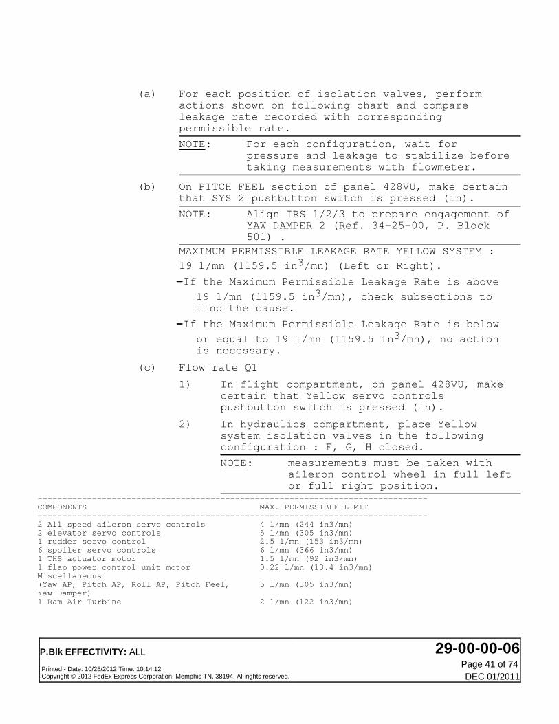
(a) For each position of isolation valves, performactions shown on following chart and compareleakage rate recorded with correspondingpermissible rate.
NOTE: For each configuration, wait forpressure and leakage to stabilize beforetaking measurements with flowmeter.
(b) On PITCH FEEL section of panel 428VU, make certainthat SYS 2 pushbutton switch is pressed (in).
NOTE: Align IRS 1/2/3 to prepare engagement ofYAW DAMPER 2 (Ref. 34-25-00, P. Block501) .
MAXIMUM PERMISSIBLE LEAKAGE RATE YELLOW SYSTEM :
19 l/mn (1159.5 in3/mn) (Left or Right).
-If the Maximum Permissible Leakage Rate is above19 l/mn (1159.5 in3/mn), check subsections tofind the cause.
-If the Maximum Permissible Leakage Rate is belowor equal to 19 l/mn (1159.5 in3/mn), no actionis necessary.
(c) Flow rate Q1
1) In flight compartment, on panel 428VU, makecertain that Yellow servo controlspushbutton switch is pressed (in).
2) In hydraulics compartment, place Yellowsystem isolation valves in the followingconfiguration : F, G, H closed.
NOTE: measurements must be taken withaileron control wheel in full leftor full right position.
-------------------------------------------------------------------------------COMPONENTS MAX. PERMISSIBLE LIMIT-------------------------------------------------------------------------------2 All speed aileron servo controls 4 l/mn (244 in3/mn)2 elevator servo controls 5 l/mn (305 in3/mn)1 rudder servo control 2.5 l/mn (153 in3/mn)6 spoiler servo controls 6 l/mn (366 in3/mn)1 THS actuator motor 1.5 l/mn (92 in3/mn)1 flap power control unit motor 0.22 l/mn (13.4 in3/mn)Miscellaneous(Yaw AP, Pitch AP, Roll AP, Pitch Feel, 5 l/mn (305 in3/mn)Yaw Damper)1 Ram Air Turbine 2 l/mn (122 in3/mn)
P.Blk EFFECTIVITY: ALL 29-00-00-06Printed - Date: 10/25/2012 Time: 10:14:12Copyright © 2012 FedEx Express Corporation, Memphis TN, 38194, All rights reserved.
Page 41 of 74DEC 01/2011

3) Leakage measurement with PITCH TRIM 1 and 2,AUTO PILOT 2, PITCH FEEL SYS 2 and YAWDAMPER 2 engaged.(Ref. Fig. 616)
NOTE: On leakage measurement diagram,the shaded areas representcomponents on which internalleakage is measured according toservo controls selector valve andisolation valves position.
-On overhead panel on PITCH FEEL section ofpanel 428VU, make certain that PITCH FEELSYS 2 (Ref. 27-33-00, P. Block 501) isstill engaged.
-Engage PITCH TRIM 1 and 2 (Ref. 22-27-00, P.Block 501) , Para. 1.A. up to andincluding (3)(b), action (1)).
-Engage YAW DAMPER 2 (Ref. 22-26-00, P. Block501) Para. 1.A. up to and up to andincluding (3)(b) action (1)).
-Engage AUTOPILOT 2 (Ref. 22-10-00, P. Block501) A.P. test in C.M.D. mode Para. 1.C.).
NOTE: Perform engagement procedure up toand including the followingactions of 1.C.(3).(b).1. :
-place AP2 lever in ON position
-press CWS/CMD pushbutton switch (CMDlegend comes on).
-Measure leakage :
NOTE: The M.P.L.R. of the Yellow system
is 19 l/mn (1159.5 in3/mn).
-Disengage PITCH TRIM 1 and 2 (Ref. 22-27-00,P. Block 501) .
-On glareshield on FCU, disengage AUTO PILOT2 (Ref. 22-10-00, P. Block 501) .
4) Leakage measurement with YAW DAMPER 2, PITCHFEEL SYS 2 engaged and AUTO PILOT 2disengaged.
NOTE: The purpose of this leakagemeasurement (AUTO PILOT 2
P.Blk EFFECTIVITY: ALL 29-00-00-06Printed - Date: 10/25/2012 Time: 10:14:12Copyright © 2012 FedEx Express Corporation, Memphis TN, 38194, All rights reserved.
Page 42 of 74DEC 01/2011

disengaged) is only to allow AUTOPILOT leakage rate determinationby comparison between the flowrate value recorded in Para. 3.and the one measured in thisparagraph.
-Engage PITCH TRIM 2 (Ref. 22-27-00, P. Block501) , Para. 1.A. up to and including (3)(b), action (1)).
-Engage YAW DAMPER 2 (Ref. 22-26-00, P. Block501) , Para. 1.A. up to and including (3)(b), action (1)).
-On overhead panel on PITCH FEEL section ofpanel 428VU, make certain that PITCH FEELSYS 2 (Ref. 27-33-00, P. Block 501) isstill engaged.
-On overhead panel, make certain that YAWDAMPER 2 is still engaged (Ref. 22-26-00,P. Block 501) Para. 1.A. up to andincluding (3)(b) action (1).
-Open, safety and tag the following circuitbreaker :
PANEL SERVICE IDENT. LOCATION
21VU AFS/AP2-FD2/FCC2/28VDC 306CA2 102/H6
-Measure leakage :
NOTE: If the difference between the flowrate value recorded in Para. 3.and the one measured in this
paragraph exceeds 3 l/mn (183 in3/mn), it is necessary to check AUTOPILOT for excessive internalleakage.
5) Restore system to normal operatingcondition.
(d) Flow rate Q2(Ref. Fig. 617)
NOTE: On leakage measurement diagram theshaded areas represent components on
P.Blk EFFECTIVITY: ALL 29-00-00-06Printed - Date: 10/25/2012 Time: 10:14:12Copyright © 2012 FedEx Express Corporation, Memphis TN, 38194, All rights reserved.
Page 43 of 74DEC 01/2011

which internal leakage is measuredaccording to servo controls selectorvalve and isolation valves position.
1) In flight compartment, on panel 428VU,release Yellow servo controls pushbuttonswitch.
2) In hydraulics compartment, make certain thatYellow system isolation valves are in thefollowing configuration : F, G, H closed.
NOTE: measured flow rate is the leakagerate of Ram Air Turbine andcomponents located downstream ofHP manifold.
-------------------------------------------------------------------------------COMPONENTS MAX. PERMISSIBLE LIMIT-------------------------------------------------------------------------------1 Flap power control unit motor 0.22 l/mn (13.4 in3/mn)1 Ram Air Turbine 2 l/mn (122 in3/mn)
3) Measure leakage
NOTE: -The M.P.L.R. of subsection Q2 is2.25 l/mn (137.2 in3/mn).
-If the M.P.L.R. of subsection Q2 isexceeded facilitate identificationof the faulty component usingmethod described in para.3.D.(3).
If flap PCU and Ram Air Turbine are withintheir max. permissible limit, check theother hydraulic components not isolatedduring the leakage measurement of Q2subsection.
4) Restore system to normal operatingcondition.
(e) Flow rate Q3(Ref. Fig. 618)
NOTE: On leakage measurement diagram theshaded areas represent components onwhich internal leakage is measuredaccording to servo controls selectorvalve and isolation valves position.
P.Blk EFFECTIVITY: ALL 29-00-00-06Printed - Date: 10/25/2012 Time: 10:14:12Copyright © 2012 FedEx Express Corporation, Memphis TN, 38194, All rights reserved.
Page 44 of 74DEC 01/2011
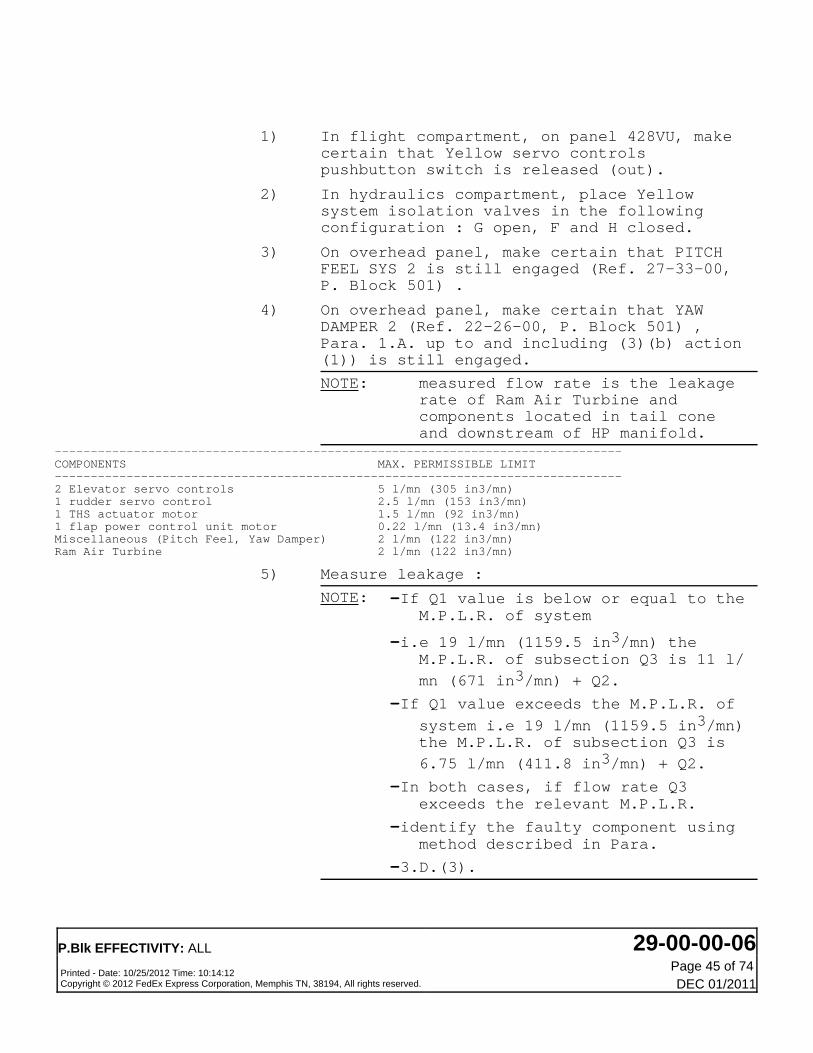
1) In flight compartment, on panel 428VU, makecertain that Yellow servo controlspushbutton switch is released (out).
2) In hydraulics compartment, place Yellowsystem isolation valves in the followingconfiguration : G open, F and H closed.
3) On overhead panel, make certain that PITCHFEEL SYS 2 is still engaged (Ref. 27-33-00,P. Block 501) .
4) On overhead panel, make certain that YAWDAMPER 2 (Ref. 22-26-00, P. Block 501) ,Para. 1.A. up to and including (3)(b) action(1)) is still engaged.
NOTE: measured flow rate is the leakagerate of Ram Air Turbine andcomponents located in tail coneand downstream of HP manifold.
-------------------------------------------------------------------------------COMPONENTS MAX. PERMISSIBLE LIMIT-------------------------------------------------------------------------------2 Elevator servo controls 5 l/mn (305 in3/mn)1 rudder servo control 2.5 l/mn (153 in3/mn)1 THS actuator motor 1.5 l/mn (92 in3/mn)1 flap power control unit motor 0.22 l/mn (13.4 in3/mn)Miscellaneous (Pitch Feel, Yaw Damper) 2 l/mn (122 in3/mn)Ram Air Turbine 2 l/mn (122 in3/mn)
5) Measure leakage :
NOTE: -If Q1 value is below or equal to theM.P.L.R. of system
-i.e 19 l/mn (1159.5 in3/mn) theM.P.L.R. of subsection Q3 is 11 l/
mn (671 in3/mn) + Q2.
-If Q1 value exceeds the M.P.L.R. ofsystem i.e 19 l/mn (1159.5 in3/mn)the M.P.L.R. of subsection Q3 is
6.75 l/mn (411.8 in3/mn) + Q2.
-In both cases, if flow rate Q3exceeds the relevant M.P.L.R.
-identify the faulty component usingmethod described in Para.
-3.D.(3).
P.Blk EFFECTIVITY: ALL 29-00-00-06Printed - Date: 10/25/2012 Time: 10:14:12Copyright © 2012 FedEx Express Corporation, Memphis TN, 38194, All rights reserved.
Page 45 of 74DEC 01/2011

6) Restore system to normal operatingcondition.
-Disengage YAW DAMPER 2 (Ref. 22-26-00, P.Block 501) .
(f) Flow rate Q4(Ref. Fig. 619)
NOTE: On leakage measurement diagram theshaded areas represent components onwhich internal leakage is measuredaccording to servo controls selectorvalve and isolation valves position.
1) On overhead panel, on panel 428VU :Make certain that Yellow servo controlspushbutton switch is released (out).
2) In hydraulics compartment, place Yellowsystem isolation valves in the followingconfiguration : F open G and H closed.
3) Make certain that aileron control wheel isin full left position.
NOTE: measured flow rate is the leakagerate of Ram Air Turbine andcomponents located in left wingand downstream of HP manifold.
-------------------------------------------------------------------------------COMPONENTS MAX. PERMISSIBLE LIMIT-------------------------------------------------------------------------------1 All speed aileron servo control 2 l/mn (122 in3/mn)3 spoiler servo controls 3 l/mn (183 in3/mn)1 flap power control unit motor 0.22 l/mn (13.4 in3/mn)1 Ram Air Turbine 2 l/mn (122 in3/mn)
4) Mesasure leakage
NOTE: -If Q1 value is below or equal to theM.P.L.R. of system i.e 19 l/mn
(1159.5 in3/mn) the M.P.L.R. of
subsection Q4 is 5 l/mn (305 in3/mn) + Q2.
-If Q1 value exceeds the M.P.L.R. ofsystem i.e 19 l/mn (1159.5 in3/mn)the M.P.L.R. of subsection Q4 is
3.5 l/mn (213.5 in3/mn) + Q2.
-In both cases, if flow rate Q4exceeds the relevant M.P.L.R.
P.Blk EFFECTIVITY: ALL 29-00-00-06Printed - Date: 10/25/2012 Time: 10:14:12Copyright © 2012 FedEx Express Corporation, Memphis TN, 38194, All rights reserved.
Page 46 of 74DEC 01/2011

-identify the faulty component usingmethod described in Para.
-3.D.(3).
5) Restore system to operation condition.
(g) Flow rate Q5(Ref. Fig. 620)
NOTE: On leakage measurement diagram, theshaded areas represent components onwhich internal leakage is measuredaccording to servo controls selectorvalve and isolation valves position.
1) On overhead panel, on panel 428VU, makecertain that Yellow servo controlspushbutton switch is released (out).
2) In hydraulics compartment, place Yellowsystem isolation valves in the followingconfiguration : H open G and F closed.
3) Make certain that aileron control wheel isin full right position.
NOTE: measured flow rate is the leakagerate of Ram Air Turbine componentslocated in right wing anddownstream of HP manifold
-------------------------------------------------------------------------------COMPONENTS MAX. PERMISSIBLE LIMIT-------------------------------------------------------------------------------1 All speed aileron servo control 2 l/mn (122 in3/mn)3 spoiler servo controls 3 l/mn (183 in3/mn)1 flap power control unit motor 0.22 l/mn (13.4 in3/mn)Ram Air Turbine 2 l/mn (122 in3/mn)
4) Measure leakage :
NOTE: -If Q1 value is below or equal to theM.P.L.R. of system i.e 19 l/mn
(1159.5 in3/mn) the M.P.L.R. of
subsection Q5 is 5 l/mn (305 in3/mn) + Q2.
-If Q1 value exceeds the M.P.L.R. ofsystem i.e 19 l/mn (1159.5 in3/mn)the M.P.L.R. of subsection Q5 is
3.5 l/mn (213.5 in3/mn) + Q2.
-In both cases, if flow are Q5exceeds the relevant M.P.L.R.,
P.Blk EFFECTIVITY: ALL 29-00-00-06Printed - Date: 10/25/2012 Time: 10:14:12Copyright © 2012 FedEx Express Corporation, Memphis TN, 38194, All rights reserved.
Page 47 of 74DEC 01/2011

identify the faulty componentusing method described in Para.
-3.D.(3).
5) Restore system to normal operatingcondition.
(3) Yellow system flow rate measurement close-up
(a) In hydraulics compartment, close the three Yellowsystem isolation valves.
(b) In flight compartment, on panel 428VU, pressYellow servo controls pushbutton switch.
(c) Remove safety clip and tag and close circuitbreaker :
(d) With Yellow system pressurized, successivelyoperate the following controls :
-elevator
-rudder
-aileronExtend and retract flaps.Make certain that components considered deflectand operate normally.
H. Close-Up
(1) Restore aircraft to normal operating condition
(a) Disconnect hydraulic ground power cart.
(b) De-energize the aircraft electrical network (Ref.24-41-00, P. Block 301) .
(c) Check fluid level in hydraulic reservoirs ; top upas required (Ref. 12-12-29, P. Block 001) .
(d) Remove all ground handling and maintenanceequipment, standard and special tools, togetherwith ground power and replenishing equipment, andmiscellaneous items.
(e) Close left main gear door (Ref. 32-12-11, P. Block301) .
(f) Remove all access equipment.
4. Check of the Nitrogen Charging Pressure on Hydraulic PowerAccumulator(1070, 2070, 3070)
P.Blk EFFECTIVITY: ALL 29-00-00-06Printed - Date: 10/25/2012 Time: 10:14:12Copyright © 2012 FedEx Express Corporation, Memphis TN, 38194, All rights reserved.
Page 48 of 74DEC 01/2011

WARNING: CHECK THAT THE LANDING GEAR GROUND SAFETIES INCLUDINGWHEEL CHOCKS ARE IN POSITION.BEFORE APPLYING OR RELIEVING HYDRAULIC SYSTEM PRESSURE,MAKE CERTAIN THAT THE TRAVEL RANGES OF THE CONTROLSURFACES ARE CLEAR.BEFORE PRESSURIZING HYDRAULIC SYSTEMS, CHECK THAT ALLCONTROLS ARE SET TO CORRESPOND WITH THE ACTUAL POSITIONOF THE SERVICES THEY OPERATE.
A. Equipment and Materials
ITEM DESIGNATION
(1)
(2)
Referenced Procedures
- (Ref. 12-14-29, P. Block 001)
- (Ref. 29-10-00, P. Block 301)
- (Ref. 29-11-56, P. Block 401)
- (Ref. 29-14-00, P. Block 301)
- (Ref. 32-12-11, P. Block 301)
Circuit Breaker Safety Clips
Warning Notices
Nitrogen Charging of Hydraulic Accumulators
Main Hydraulic Power - Pressurization/
Depressurization
Accumulator
Hydraulic Reservoir Pressurizing System
Main Gear Main Door - (Ground Door(s)Opening)
B. Procedure
(1) Job Set-Up
(a) On panel 427VU:
-Display a warning notice prohibiting operation ofGreen, Blue or Yellow system.
(b) Open, safety and tag the following circuitbreakers :
PANEL SERVICE IDENT. LOCATION
101VU
101VU
133VU
133VU
133VU
133VU
HYD/PUMP
HYD/PUMP
ELEC/PUMPS/WARN
PTU CTL/G/B
PTU CTL/G/Y
ACCU PRESS/CTL &/CARGO DOOR/PUMP
1GE
2GE
4GE
1GL
6GL
7GX
GEN1/B8
GEN2/B8
331/V60
332/U59
332/U60
333/T51
P.Blk EFFECTIVITY: ALL 29-00-00-06Printed - Date: 10/25/2012 Time: 10:14:12Copyright © 2012 FedEx Express Corporation, Memphis TN, 38194, All rights reserved.
Page 49 of 74DEC 01/2011

(c) Open access doors 147AL, 571BB and 671BB tohydraulic ground connectors.
(d) Open main landing gear doors (Ref. 32-12-11, P.Block 301) .
(e) Depressurize Green, Blue or Yellow hydraulicreservoir, as appropriate (Ref. 29-14-00, P. Block301) .
(f) Display a warning notice on ground connectorsprohibiting pressurization of Green, Blue orYellow system.
(g) Depressurize Green, Blue or Yellow hydraulicsystem (Ref. 29-10-00, P. Block 301) .
(2) Check of the precharge pressure.
(a) Refer to the pressure gages on each systemaccumulator, and make sure that the prechargepressures are as follows :
Temperature Charging pressure
deg.C deg.F bar PSI
-20
-10
-0+10
+20
+30
+40
+60
-4+14
+32
+50
+68
+86
+104
+140
86
90
93
97
100
104
107
111
1247
1305
1349
1407
1450
1508
1522
1653
NOTE: If you do this check immediately afteraircraft landing, let the pressurebecome stable for one hour to get a moreaccurate measurement (temperaturecompensation of the accumulator).
P.Blk EFFECTIVITY: ALL 29-00-00-06Printed - Date: 10/25/2012 Time: 10:14:12Copyright © 2012 FedEx Express Corporation, Memphis TN, 38194, All rights reserved.
Page 50 of 74DEC 01/2011

(3) If the pressures are not correct continue as follows :
(a) If the pressure differential between the read andthe nominal pressure is less than or equal to 30bars (440 psi) :
-adjust the pressure as necessary (Ref. 12-14-29,P. Block 001) .
(b) If the pressure differential is more than 30 bars(440 psi) :
-do a leak check on the following components :-accumulator connections.
-power accumulator pressure gage.
-nitrogen charging valve.
-power accumulator.
-if possible stop any leaks and then pressurize theaccumulator (Ref. 12-14-29, P. Block 001) .
-if it is not possible to stop the leaks, replacethe concerned components (Ref. 29-11-56, P.Block 401) .
-power accumulator pressure gage.
-nitrogen charging valve.
-power accumulator.
-pressurize the accumulator and adjust the pressure(Ref. 12-14-29, P. Block 001) .
P.Blk EFFECTIVITY: ALL 29-00-00-06Printed - Date: 10/25/2012 Time: 10:14:12Copyright © 2012 FedEx Express Corporation, Memphis TN, 38194, All rights reserved.
Page 51 of 74DEC 01/2011

(4) Close-up
(a) Close main landing gear doors (Ref. 32-12-11, P.Block 301) .
(b) Remove the warning notices.
(c) Close the access doors.
(d) Remove safety clips and tags and close circuitbreakers 1GE, 2GE, 4GE, 1GL, 6GL and 7GX.
P.Blk EFFECTIVITY: ALL 29-00-00-06Printed - Date: 10/25/2012 Time: 10:14:12Copyright © 2012 FedEx Express Corporation, Memphis TN, 38194, All rights reserved.
Page 52 of 74DEC 01/2011

Figure 601Figure 601. Draining System(Sheet 1)
P.Blk EFFECTIVITY: ALL 29-00-00-06Printed - Date: 10/25/2012 Time: 10:14:12Copyright © 2012 FedEx Express Corporation, Memphis TN, 38194, All rights reserved.
Page 53 of 74DEC 01/2011
FED 731-739
P.Blk EFFECTIVITY: ALL 29-00-00-06Printed - Date: 10/25/2012 Time: 10:14:12Copyright © 2012 FedEx Express Corporation, Memphis TN, 38194, All rights reserved.
Page 54 of 74DEC 01/2011

Figure 602Figure 602. Draining System(Sheet 1)
P.Blk EFFECTIVITY: ALL 29-00-00-06Printed - Date: 10/25/2012 Time: 10:14:12Copyright © 2012 FedEx Express Corporation, Memphis TN, 38194, All rights reserved.
Page 55 of 74DEC 01/2011

FED 716-730,740-746,748-799
P.Blk EFFECTIVITY: ALL 29-00-00-06Printed - Date: 10/25/2012 Time: 10:14:12Copyright © 2012 FedEx Express Corporation, Memphis TN, 38194, All rights reserved.
Page 56 of 74DEC 01/2011

Figure 603Figure 603. Flow Rate Chart(Sheet 1)
P.Blk EFFECTIVITY: ALL 29-00-00-06Printed - Date: 10/25/2012 Time: 10:14:12Copyright © 2012 FedEx Express Corporation, Memphis TN, 38194, All rights reserved.
Page 57 of 74DEC 01/2011

FED ALL
Figure 604Figure 604. Leakage Measurement Diagram (Flow Rate Q1 - Green System)
(Sheet 1)
FED ALL
P.Blk EFFECTIVITY: ALL 29-00-00-06Printed - Date: 10/25/2012 Time: 10:14:12Copyright © 2012 FedEx Express Corporation, Memphis TN, 38194, All rights reserved.
Page 58 of 74DEC 01/2011

Figure 605Figure 605. Leakage Measurement Diagram (Flow Rate Q2 - Green System)
(Sheet 1)
FED ALL
P.Blk EFFECTIVITY: ALL 29-00-00-06Printed - Date: 10/25/2012 Time: 10:14:12Copyright © 2012 FedEx Express Corporation, Memphis TN, 38194, All rights reserved.
Page 59 of 74DEC 01/2011

Figure 606Figure 606. Leakage Measurement Diagram (Flow Rate Q3 - Green System)
(Sheet 1)
FED ALL
P.Blk EFFECTIVITY: ALL 29-00-00-06Printed - Date: 10/25/2012 Time: 10:14:12Copyright © 2012 FedEx Express Corporation, Memphis TN, 38194, All rights reserved.
Page 60 of 74DEC 01/2011

Figure 607Figure 607. Leakage Measurement Diagram (Flow Rate Q4 - Green system)
(Sheet 1)
FED ALL
P.Blk EFFECTIVITY: ALL 29-00-00-06Printed - Date: 10/25/2012 Time: 10:14:12Copyright © 2012 FedEx Express Corporation, Memphis TN, 38194, All rights reserved.
Page 61 of 74DEC 01/2011
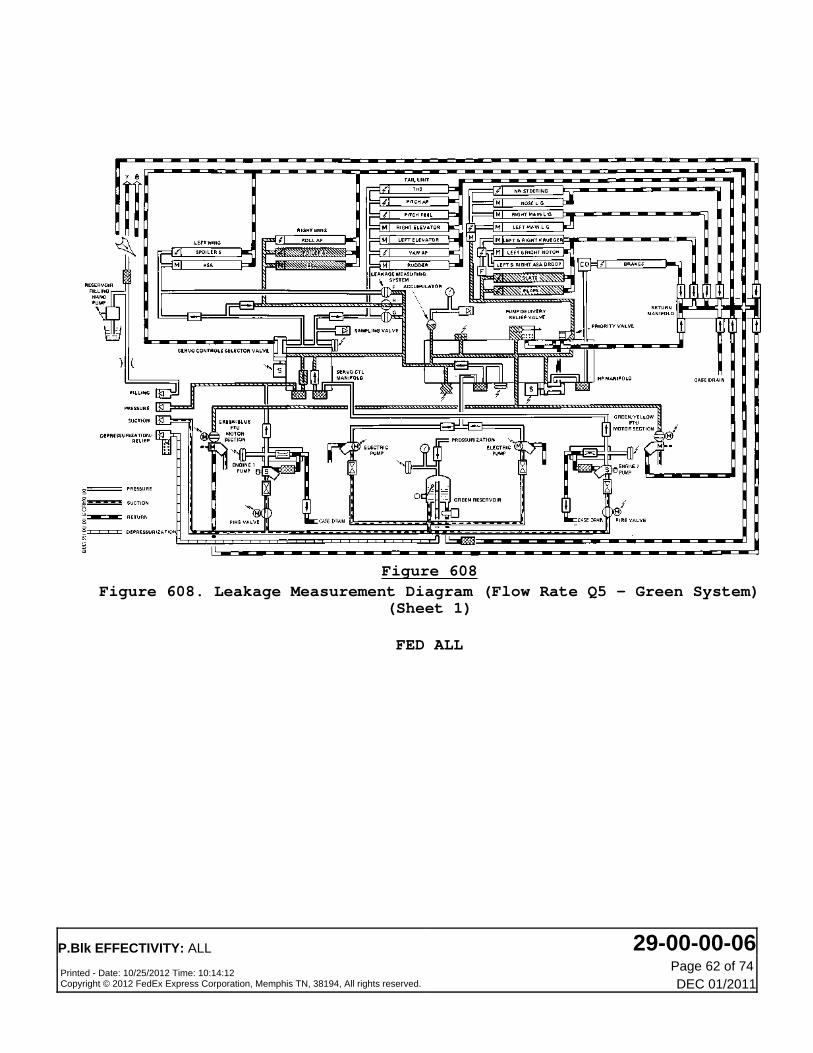
Figure 608Figure 608. Leakage Measurement Diagram (Flow Rate Q5 - Green System)
(Sheet 1)
FED ALL
P.Blk EFFECTIVITY: ALL 29-00-00-06Printed - Date: 10/25/2012 Time: 10:14:12Copyright © 2012 FedEx Express Corporation, Memphis TN, 38194, All rights reserved.
Page 62 of 74DEC 01/2011

Figure 609Figure 609. Flow Rate Chart(Sheet 1)
P.Blk EFFECTIVITY: ALL 29-00-00-06Printed - Date: 10/25/2012 Time: 10:14:12Copyright © 2012 FedEx Express Corporation, Memphis TN, 38194, All rights reserved.
Page 63 of 74DEC 01/2011

FED ALL
Figure 610Figure 610. Leakage Measurement Diagram (Flow Rate Q1 - Blue System)
(Sheet 1)
FED ALL
P.Blk EFFECTIVITY: ALL 29-00-00-06Printed - Date: 10/25/2012 Time: 10:14:12Copyright © 2012 FedEx Express Corporation, Memphis TN, 38194, All rights reserved.
Page 64 of 74DEC 01/2011

Figure 611Figure 611. Leakage Measurement Diagram (Flow Rate Q2 - Blue System)
(Sheet 1)
FED ALL
P.Blk EFFECTIVITY: ALL 29-00-00-06Printed - Date: 10/25/2012 Time: 10:14:12Copyright © 2012 FedEx Express Corporation, Memphis TN, 38194, All rights reserved.
Page 65 of 74DEC 01/2011

Figure 612Figure 612. Leakage Measurement Diagram (Flow Rate Q3 - Blue System)
(Sheet 1)
FED ALL
P.Blk EFFECTIVITY: ALL 29-00-00-06Printed - Date: 10/25/2012 Time: 10:14:12Copyright © 2012 FedEx Express Corporation, Memphis TN, 38194, All rights reserved.
Page 66 of 74DEC 01/2011

Figure 613Figure 613. Leakage Measurement Diagram (Flow Rate Q4 - Blue System)
(Sheet 1)
FED ALL
P.Blk EFFECTIVITY: ALL 29-00-00-06Printed - Date: 10/25/2012 Time: 10:14:12Copyright © 2012 FedEx Express Corporation, Memphis TN, 38194, All rights reserved.
Page 67 of 74DEC 01/2011

Figure 614Figure 614. Leakage Measurement Diagram (Flow Rate Q5 - Blue System)
(Sheet 1)
FED ALL
P.Blk EFFECTIVITY: ALL 29-00-00-06Printed - Date: 10/25/2012 Time: 10:14:12Copyright © 2012 FedEx Express Corporation, Memphis TN, 38194, All rights reserved.
Page 68 of 74DEC 01/2011

Figure 615Figure 615. Flow Rate Chart(Sheet 1)
P.Blk EFFECTIVITY: ALL 29-00-00-06Printed - Date: 10/25/2012 Time: 10:14:12Copyright © 2012 FedEx Express Corporation, Memphis TN, 38194, All rights reserved.
Page 69 of 74DEC 01/2011

FED ALL
Figure 616Figure 616. Leakage Measurement Diagram (Flow Rate Q1 - Yellow System)
(Sheet 1)
FED ALL
P.Blk EFFECTIVITY: ALL 29-00-00-06Printed - Date: 10/25/2012 Time: 10:14:12Copyright © 2012 FedEx Express Corporation, Memphis TN, 38194, All rights reserved.
Page 70 of 74DEC 01/2011

Figure 617Figure 617. Leakage Measurement Diagram (Flow Rate Q2 - Yellow System)
(Sheet 1)
FED ALL
P.Blk EFFECTIVITY: ALL 29-00-00-06Printed - Date: 10/25/2012 Time: 10:14:12Copyright © 2012 FedEx Express Corporation, Memphis TN, 38194, All rights reserved.
Page 71 of 74DEC 01/2011
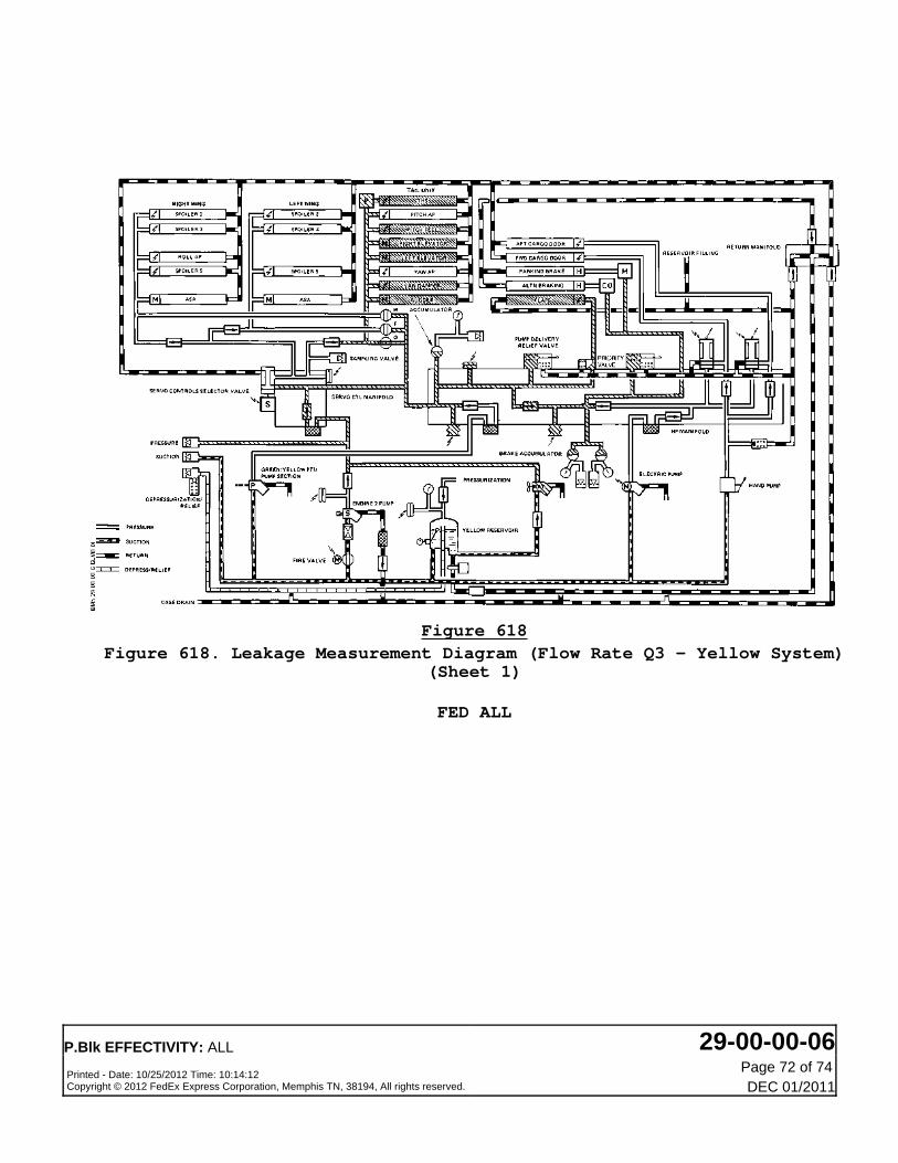
Figure 618Figure 618. Leakage Measurement Diagram (Flow Rate Q3 - Yellow System)
(Sheet 1)
FED ALL
P.Blk EFFECTIVITY: ALL 29-00-00-06Printed - Date: 10/25/2012 Time: 10:14:12Copyright © 2012 FedEx Express Corporation, Memphis TN, 38194, All rights reserved.
Page 72 of 74DEC 01/2011

Figure 619Figure 619. Leakage Measurement Diagram (Flow Rate Q4 - Yellow System)
(Sheet 1)
FED ALL
P.Blk EFFECTIVITY: ALL 29-00-00-06Printed - Date: 10/25/2012 Time: 10:14:12Copyright © 2012 FedEx Express Corporation, Memphis TN, 38194, All rights reserved.
Page 73 of 74DEC 01/2011

Figure 620Figure 620. Leakage Measurement Diagram (Flow Rate Q5 - Yellow System)
(Sheet 1)
FED ALL
P.Blk EFFECTIVITY: ALL 29-00-00-06Printed - Date: 10/25/2012 Time: 10:14:12Copyright © 2012 FedEx Express Corporation, Memphis TN, 38194, All rights reserved.
Page 74 of 74DEC 01/2011