![DK Hostmaster’s General Conditions Version 07 · DK Hostmaster’s General Conditions Version 07 [1] DK HOSTMASTER’S GENERAL CONDITIONS FOR THE ASSIGNMENT, REGISTRATION AND ADMINISTRATION](https://static.fdocuments.net/doc/165x107/5f0755977e708231d41c786f/dk-hostmasteras-general-conditions-version-07-dk-hostmasteras-general-conditions.jpg)
GENERAL INFORMATION B C D E Eo Dk - pistrik.ee
2
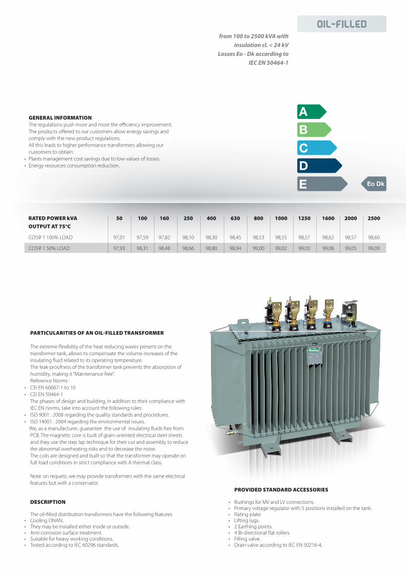
Oil-filled RATED POWER kVA 50 100 160 250 400 630 800 1000 1250 1600 2000 2500 OUTPUT AT 75°C COS φ 1 100% LOAD 97,01 97,59 97,82 98,10 98,30 98,45 98,53 98,55 98,57 98,62 98,57 98,60 COS φ 1 50% LOAD 97,93 98,31 98,48 98,66 98,80 98,94 99,00 99,02 99,03 99,06 99,05 99,09 GENERAL INFORMATION The regulations push more and more the efficiency improvement. The products offered to our customers allow energy savings and comply with the new product regulations. All this leads to higher performance transformers allowing our customers to obtain: • Plants management cost savings due to low values of losses. • Energy resources consumption reduction. from 100 to 2500 kVA with insulation cl. < 24 kV Losses Eo - Dk according to IEC EN 50464-1 C A Eo Dk B D E PARTICULARITIES OF AN OILFILLED TRANSFORMER The extreme flexibility of the heat reducing waves present on the transformer tank, allows to compensate the volume increases of the insulating fluid related to its operating temperature. The leak-proofness of the transformer tank prevents the absorption of humidity, making it “Maintenance free”. Reference Norms : • CEI EN 60067-1 to 10 • CEI EN 50464-1 The phases of design and building, in addition to their compliance with IEC EN norms, take into account the following rules: • ISO 9001 : 2008 regarding the quality standards and procedures. • ISO 14001 : 2004 regarding the environmental issues. We, as a manufacturer, guarantee the use of insulating fluids free from PCB. The magnetic core is built of grain-oriented electrical steel sheets and they use the step lap technique for their cut and assembly to reduce the abnormal overheating risks and to decrease the noise. The coils are designed and built so that the transformer may operate on full-load conditions in strict compliance with A thermal class. Note: on request, we may provide transformers with the same electrical features but with a conservator. DESCRIPTION The oil-filled distribution transformers have the following features • Cooling ONAN. • They may be installed either inside or outside. • Anti-corrosion surface treatment. • Suitable for heavy working conditions. • Tested according to IEC 60296 standards. PROVIDED STANDARD ACCESSORIES • Bushings for MV and LV connections. • Primary voltage regulator with 5 positions installed on the tank. • Rating plate. • Lifting lugs. • 2 Earthing points. • 4 Bi-directional flat rollers. • Filling valve. • Drain valve according to IEC EN 50216-4.
Transcript of GENERAL INFORMATION B C D E Eo Dk - pistrik.ee
Oil-filled
RATED POWER kVA 50 100 160 250 400 630 800 1000 1250 1600 2000 2500
OUTPUT AT 75°C
COSφ 1 100% LOAD 97,01 97,59 97,82 98,10 98,30 98,45 98,53 98,55 98,57 98,62 98,57 98,60
COSφ 1 50% LOAD 97,93 98,31 98,48 98,66 98,80 98,94 99,00 99,02 99,03 99,06 99,05 99,09
GENERAL INFORMATION The regulations push more and more the effi ciency improvement. The products off ered to our customers allow energy savings and
comply with the new product regulations. All this leads to higher performance transformers allowing our
customers to obtain:• Plants management cost savings due to low values of losses.• Energy resources consumption reduction.
from 100 to 2500 kVA with
insulation cl. < 24 kV
Losses Eo - Dk according to
IEC EN 50464-1
C
A
Eo Dk
B
DE
PARTICULARITIES OF AN OILFILLED TRANSFORMER
The extreme fl exibility of the heat reducing waves present on the transformer tank, allows to compensate the volume increases of the
insulating fl uid related to its operating temperature. The leak-proofness of the transformer tank prevents the absorption of
humidity, making it “Maintenance free”. Reference Norms :• CEI EN 60067-1 to 10• CEI EN 50464-1 The phases of design and building, in addition to their compliance with
IEC EN norms, take into account the following rules:• ISO 9001 : 2008 regarding the quality standards and procedures.• ISO 14001 : 2004 regarding the environmental issues. We, as a manufacturer, guarantee the use of insulating fl uids free from PCB. The magnetic core is built of grain-oriented electrical steel sheets and they use the step lap technique for their cut and assembly to reduce
the abnormal overheating risks and to decrease the noise. The coils are designed and built so that the transformer may operate on
full-load conditions in strict compliance with A thermal class.
Note: on request, we may provide transformers with the same electrical features but with a conservator.
DESCRIPTION
The oil-fi lled distribution transformers have the following features• Cooling ONAN.• They may be installed either inside or outside.• Anti-corrosion surface treatment.• Suitable for heavy working conditions.• Tested according to IEC 60296 standards.
PROVIDED STANDARD ACCESSORIES
• Bushings for MV and LV connections.• Primary voltage regulator with 5 positions installed on the tank.• Rating plate.• Lifting lugs.• 2 Earthing points.• 4 Bi-directional fl at rollers.• Filling valve.• Drain valve according to IEC EN 50216-4.
Scheda MF_Trasformatori_Olio_EN.indd 9 21/03/14 13.19
vadim_000
Accepted

FROM 100 TO 2500 KVA WITHINSULATION CL. 24 KVLOSSES Eo Dk ACCORDING TOIEC EN 504641
RATED POWER kVA 50 100 160 250 400 630 800 1000 1250 1600 2000 2500 NOLOAD LOSSES W 190 320 460 650 930 1.200 1.400 1.700 2.100 2.600 3.100 3.500 LOAD LOSSES AT 75 °C W 1.350 2.150 3.100 4.200 6.000 8.700 10.500 13.000 16.000 20.000 26.000 32.000 NOLOAD CURRENT Io % 1 0,9 0,6 0,6 0,6 0,6 0,6 0,6 0,6 0,4 0,4 0,4 SHORT CIRCUIT VOLTAGE VCC % 4 4 4 4 4 6 6 6 6 6 6 6 INPUT CURRENT IE/IN 11,6 10,6 10,10 9,2 9,4 9 8,4 8,4 8,8 8 7,6 7,5
OUTPUT AT 75°C COSφ 1 100% LOAD % 97,01 97,59 97,82 98,10 98,30 98,45 98,53 98,55 98,57 98,62 98,57 98,60 COSφ 1 75% LOAD % 97,53 98,00 98,20 98,42 98,59 98,73 98,80 98,81 98,83 98,86 98,83 98,87 COSφ 0,9 100% LOAD % 96,69 97,33 97,59 97,89 98,11 98,28 98,37 98,39 98,42 98,45 98,41 98,45 COSφ 0,9 75% LOAD % 97,26 97,78 98,00 98,25 98,43 98,59 98,67 98,68 98,70 98,73 98,70 98,74
VOLTAGE DROP AT 75° C COSφ 1 100% LOAD % 2,74 2,21 2,00 1,75 1,37 1,55 1,48 1,47 1,45 1,42 1,47 1,45 COSφ 0,9 100% LOAD % 3,73 3,43 3,30 3,13 3 3,9 3,84 3,83 3,82 3,8 3,83 3,82
HERMETICALLY SEALED TRANSFORMER 50 100 160 250 400 630 800 1000 1250 1600 2000 2500 LENGTH A mm 850 900 1.000 1.100 1.250 1.500 1.550 1.650 1.800 1.850 2.100 2.150 DEPTH B mm 500 600 600 700 800 900 900 1.000 1.100 1.100 1.200 1.300 HEIGHT C mm 800 900 1.000 1.100 1.200 1.300 1.300 1.400 1.400 1.500 1.800 1.850 WHEEL INTERAXIS D mm 400 520 520 520 670 670 820 820 820 820 1.000 1.000 WHEEL DIAMETER mm 150 150 150 150 150 150 150 150 150 150 150 150 OIL WEIGHT kg 80 110 140 200 240 370 410 480 560 650 810 860 TOTAL WEIGHT kg 400 500 650 910 1.200 1.625 1.850 2.250 2.550 3.150 3.750 4.300
TRANSFORMER WITH CONSERVATOR 50 100 160 250 400 630 800 1000 1250 1600 2000 2500 LENGTH A mm 850 900 1.000 1.100 1.250 1.500 1.550 1.650 1.800 1.850 2.100 2.150 DEPTH B mm 500 600 600 700 800 900 900 1.000 1.100 1.100 1.200 1.300 HEIGHT C mm 900 1.000 1.080 1.220 1.300 1.400 1.520 1.720 1.600 1.700 2.000 2.000 WHEEL INTERAXIS D mm 400 520 520 520 670 670 820 820 820 820 1.000 1.000 WHEEL DIAMETER mm 150 150 150 150 150 150 150 150 150 150 150 150 OIL WEIGHT kg 85 115 145 205 240 380 420 495 575 675 835 885 TOTAL WEIGHT kg 405 510 660 920 1.220 1.650 1.875 2.275 2.580 3.180 3.800 4.350
DDB
C C
ADA
DB
SIZES AND WEIGHTS APPROXIMATE
Hermetically Sealed Transformer Transformer with conservator
Oil-filled
NOISE SOUND POWER LEVEL Lwa dB(A) 55 59 62 65 68 70 71 73 74 76 78 81
Scheda MF_Trasformatori_Olio_EN.indd 10 21/03/14 13.19