
General Gas Engineering - System Technik · EN 60529 Degrees of protection provided by enclosures...
52
Edition 09.13 Gas Engineering Planning Manual General Gas Engineering
Transcript of General Gas Engineering - System Technik · EN 60529 Degrees of protection provided by enclosures...
Edition 09.13
Gas Engineering Planning Manual
General Gas Engineering


1
Overview sheet of the DVGW regulations to be complied with........................................ 4
Overview sheet of important DIN and VDE sheets .......................................................... 5
European Directives ....................................................................................................... 5
European Standards / Draft Standards ..........................................................................6
International Standards / Draft Standards .......................................................................6
American Standards .......................................................................................................6
What are gas and characteristic gas values? .................................................................. 7
What is pressure? ......................................................................................................... 14
What are volume, flow rate and flow velocity? ..............................................................16
What is temperature? ...................................................................................................18
What are mass, atomic mass and molecular mass? .....................................................19
What are work, energy and quantity of heat? ...............................................................20
What are power, energy and heat flux?......................................................................... 21
What are density and relative density? .......................................................................... 22
What are quantity of heat, calorific value, gross calorific value and Wobbe index? ........23
Summary of electrical formulae .................................................................................... 24
Enclosure in accordance with DIN EN 60529 (IP) .........................................................30
Whitworth pipe threads for threaded pipes and fittings ................................................. 32
Flange dimensions in accordance with DIN ..................................................................36
Flow velocities in pipes .................................................................................................38
Pressure loss in pipes ...................................................................................................39
Volume of pipes ............................................................................................................40
Dimensions of pipes ..................................................................................................... 41
Colour coding for pipes in accordance with DIN 2403 .................................................. 42
Greek letters ................................................................................................................. 42
Designation of decimal multiple units ............................................................................ 42
Symbols used in formulae and units used for physical quantities ..................................43
Conversion of quantities for atmospheric pressure ....................................................... 44
Weights, mass ..............................................................................................................46
Temperature .................................................................................................................46
Density .........................................................................................................................46
Force units (force due to weight) ..................................................................................46
Time units .....................................................................................................................46
Length units ................................................................................................................. 47
Area units ..................................................................................................................... 47
Volume, capacity units .................................................................................................. 47
Power .......................................................................................................................... 47
Specific heat ................................................................................................................ 47
Work, energy, quantity of heat ......................................................................................48
Resistance table ...........................................................................................................49
Contents Page
2
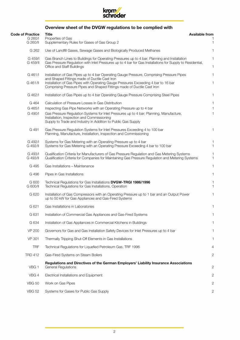
Overview sheet of the DVGW regulations to be complied with Code of Practice Title Available from G 260/I Properties of Gas 1 G 260/II Supplementary Rules for Gases of Gas Group 2 1
G 262 Use of Landfill Gases, Sewage Gases and Biologically Produced Methanes 1
G 459/I Gas Branch Lines to Buildings for Operating Pressures up to 4 bar; Planning and Installation 1 G 459/II Gas Pressure Regulation with Inlet Pressures up to 4 bar for Gas Installations for Supply to Residential, Office and Staff Buildings 1
G 461/I Installation of Gas Pipes up to 4 bar Operating Gauge Pressure, Comprising Pressure Pipes 1 and Shaped Fittings made of Ductile Cast Iron G 461/II Installation of Gas Pipes with Operating Gauge Pressures Exceeding 4 bar to 16 bar 1 Comprising Pressure Pipes and Shaped Fittings made of Ductile Cast Iron
G 462/I Installation of Gas Pipes up to 4 bar Operating Gauge Pressure Comprising Steel Pipes 1
G 464 Calculation of Pressure Losses in Gas Distribution 1 G 465/I Inspecting Gas Pipe Networks with an Operating Pressure up to 4 bar 1 G 490/I Gas Pressure Regulation Systems for Inlet Pressures up to 4 bar; Planning, Manufacture, 1 Installation, Inspection and Commissioning Supply to Trade and Industry in Addition to Public Gas Supply
G 491 Gas Pressure Regulation Systems for Inlet Pressures Exceeding 4 to 100 bar 1 Planning, Manufacture, Installation, Inspection and Commissioning
G 492/I Systems for Gas Metering with an Operating Pressure up to 4 bar 1 G 492/II Systems for Gas Metering with an Operating Pressure Exceeding 4 bar to 100 bar 1
G 493/I Qualification Criteria for Manufacturers of Gas Pressure Regulation and Gas Metering Systems 1 G 493/II Qualification Criteria for Companies for Maintaining Gas Pressure Regulation and Metering Systems 1
G 495 Gas Installations – Maintenance 1
G 496 Pipes in Gas Installations 1
G 600 Technical Regulations for Gas Installations DVGW-TRGI 1986/1996 1 G 600/II Technical Regulations for Gas Installations, Operation 1
G 620 Installation of Gas Compressors with an Operating Pressure up to 1 bar and an Output Power 1 up to 50 kW for Gas Appliances and Gas-Fired Systems
G 621 Gas Installations in Laboratories 1
G 631 Installation of Commercial Gas Appliances and Gas-Fired Systems 1
G 634 Installation of Gas Appliances in Commercial Kitchens in Buildings 1
VP 200 Governors for Gas and Gas Installation Safety Devices for Inlet Pressures up to 4 bar 1
VP 301 Thermally Tripping Shut-Off Elements in Gas Installations 1
TRF Technical Regulations for Liquefied Petroleum Gas, TRF 1996 4
TRD 412 Gas-Fired Systems on Steam Boilers 2
Regulations and Directives of the German Employers’ Liability Insurance Associations VBG 1 General Regulations 2
VBG 4 Electrical Installations and Equipment 2
VBG 50 Work on Gas Pipes 2
VBG 52 Systems for Gases for Public Gas Supply 2
3
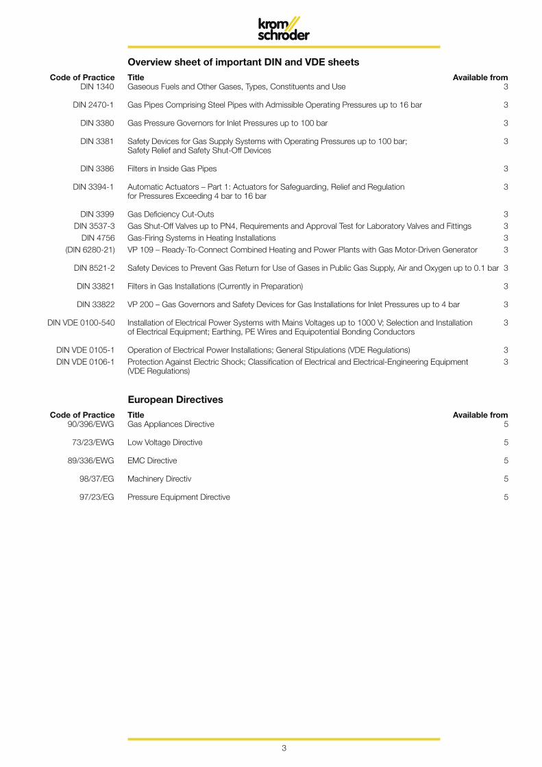
Overview sheet of important DIN and VDE sheets Code of Practice Title Available from DIN 1340 Gaseous Fuels and Other Gases, Types, Constituents and Use 3
DIN 2470-1 Gas Pipes Comprising Steel Pipes with Admissible Operating Pressures up to 16 bar 3
DIN 3380 Gas Pressure Governors for Inlet Pressures up to 100 bar 3
DIN 3381 Safety Devices for Gas Supply Systems with Operating Pressures up to 100 bar; 3 Safety Relief and Safety Shut-Off Devices
DIN 3386 Filters in Inside Gas Pipes 3
DIN 3394-1 Automatic Actuators – Part 1: Actuators for Safeguarding, Relief and Regulation 3 for Pressures Exceeding 4 bar to 16 bar
DIN 3399 Gas Deficiency Cut-Outs 3 DIN 3537-3 Gas Shut-Off Valves up to PN4, Requirements and Approval Test for Laboratory Valves and Fittings 3 DIN 4756 Gas-Firing Systems in Heating Installations 3 (DIN 6280-21) VP 109 – Ready-To-Connect Combined Heating and Power Plants with Gas Motor-Driven Generator 3
DIN 8521-2 Safety Devices to Prevent Gas Return for Use of Gases in Public Gas Supply, Air and Oxygen up to 0.1 bar 3
DIN 33821 Filters in Gas Installations (Currently in Preparation) 3
DIN 33822 VP 200 – Gas Governors and Safety Devices for Gas Installations for Inlet Pressures up to 4 bar 3
DIN VDE 0100-540 Installation of Electrical Power Systems with Mains Voltages up to 1000 V; Selection and Installation 3 of Electrical Equipment; Earthing, PE Wires and Equipotential Bonding Conductors
DIN VDE 0105-1 Operation of Electrical Power Installations; General Stipulations (VDE Regulations) 3 DIN VDE 0106-1 Protection Against Electric Shock; Classification of Electrical and Electrical-Engineering Equipment 3 (VDE Regulations)
European Directives Code of Practice Title Available from 90/396/EWG Gas Appliances Directive 5
73/23/EWG Low Voltage Directive 5
89/336/EWG EMC Directive 5
98/37/EG Machinery Directiv 5
97/23/EG Pressure Equipment Directive 5
4
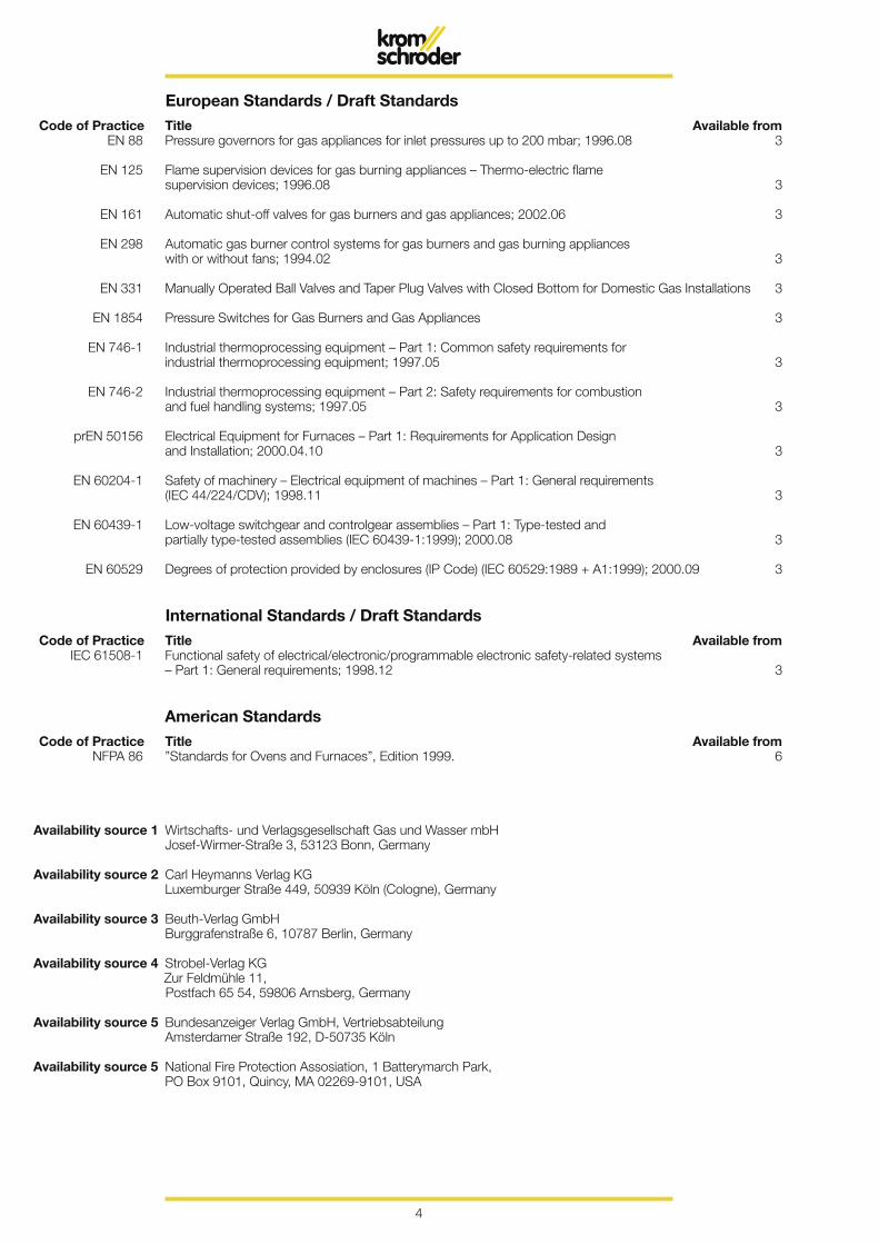
European Standards / Draft Standards Code of Practice Title Available from EN 88 Pressure governors for gas appliances for inlet pressures up to 200 mbar; 1996.08 3
EN 125 Flame supervision devices for gas burning appliances – Thermo-electric flame supervision devices; 1996.08 3
EN 161 Automatic shut-off valves for gas burners and gas appliances; 2002.06 3
EN 298 Automatic gas burner control systems for gas burners and gas burning appliances with or without fans; 1994.02 3
EN 331 Manually Operated Ball Valves and Taper Plug Valves with Closed Bottom for Domestic Gas Installations 3
EN 1854 Pressure Switches for Gas Burners and Gas Appliances 3
EN 746-1 Industrial thermoprocessing equipment – Part 1: Common safety requirements for industrial thermoprocessing equipment; 1997.05 3
EN 746-2 Industrial thermoprocessing equipment – Part 2: Safety requirements for combustion and fuel handling systems; 1997.05 3
prEN 50156 Electrical Equipment for Furnaces – Part 1: Requirements for Application Design and Installation; 2000.04.10 3
EN 60204-1 Safety of machinery – Electrical equipment of machines – Part 1: General requirements (IEC 44/224/CDV); 1998.11 3
EN 60439-1 Low-voltage switchgear and controlgear assemblies – Part 1: Type-tested and partially type-tested assemblies (IEC 60439-1:1999); 2000.08 3
EN 60529 Degrees of protection provided by enclosures (IP Code) (IEC 60529:1989 + A1:1999); 2000.09 3
International Standards / Draft Standards Code of Practice Title Available from IEC 61508-1 Functional safety of electrical/electronic/programmable electronic safety-related systems – Part 1: General requirements; 1998.12 3
American Standards Code of Practice Title Available from NFPA 86 ”Standards for Ovens and Furnaces”, Edition 1999. 6
Availability source 1 Wirtschafts- und Verlagsgesellschaft Gas und Wasser mbH Josef-Wirmer-Straße 3, 53123 Bonn, Germany
Availability source 2 Carl Heymanns Verlag KG Luxemburger Straße 449, 50939 Köln (Cologne), Germany
Availability source 3 Beuth-Verlag GmbH Burggrafenstraße 6, 10787 Berlin, Germany
Availability source 4 Strobel-Verlag KG Zur Feldmühle 11, Postfach 65 54, 59806 Arnsberg, Germany
Availability source 5 Bundesanzeiger Verlag GmbH, Vertriebsabteilung Amsterdamer Straße 192, D-50735 Köln
Availability source 5 National Fire Protection Assosiation, 1 Batterymarch Park, PO Box 9101, Quincy, MA 02269-9101, USA

5
What is fuel gas? A gas or gas mixture which is combustible in a specific mixing ratio with oxygen (in ac-cordance with DIN 1340).
What are gas and characteristic gas values?Miscellaneous / useful information from the gas sector
What fuel gases are important? Natural gas, liquefied petroleum gas (LPG) and biologically produced methanes.
What is natural gas? A natural product.
How is natural gas produced? From animal and vegetable deposits on the beds of the primeval oceans which have been chemically converted to hydrocar-bons under high pressure exerted by rock and soil layers over millions of years.
Since when has natural gas been known?
It can be proven that Indo-Europeans in the Caucasus referred to burning natu-ral gas as “Eternal Fire” over 5,000 years ago. Sumerian and Assyrian priests used the gases streaming from the earth for their prophecies.
What does natural gas consist of? Chiefly of the combustible hydrocarbon compound methane (CH4).
What natural gas qualities are there and what do they mean?
We chiefly distinguish between the natural gas qualities L and H.
“L” stands for low and means that this natu-ral gas has a gross calorific value of approx. 9.77 kWh/m3. It is produced from German and Dutch gas fields.
“H” stands for high and means that this natural gas has a gross calorific value of approx. 11.5 kWh/m3. It is produced pri-marily from the gas fields of the North Sea and the former Soviet Union.
When and where was the first natural gas field discovered?
In 1815 in a salt mine in Charleston, West Virginia.
… and in Germany? In 1910 when drilling for water in Neu-engamme near Hamburg.
6
When was natural gas used commer-cially for the first time?
In around 900 BC, the Chinese used natural gas to dry salt for the first time, in accordance with the reports of English chroniclers.
Why is natural gas stored? Since the daily natural gas consumption is subject to major fluctuations depending on season, it is necessary, for economic rea-sons, to ensure provision of the required quantity of gas in peak demand periods by storing natural gas in times in which de-mand is not so high.
How is natural gas stored? In gaseous state.Above-ground tanks are used to provide small quantities of gas for daily use. Larger quantities of gas are stored in porous un-derground storage structures comprising porous rock or cave stores (salt dome stores).
What types of gas pipes are there and at what pressures is the gas in them transported?
Main transport pipes, also referred to as long-distance gas pipes, are high-pressure pipes operated at a maximum pressure of 80 bar.Medium and low-pressure pipes of regional and local gas supply utilities ensure that the gas is forwarded to the consumers. A mini-mum pressure of 20 mbar for natural gas is used in such pipes.
How long has the first long-distance gas pipe been in existence in Germany?
At the instigation of August Thyssen, the first German long-distance gas pipe was laid in 1910 from Duisburg-Hamborn to Wuppertal-Barmen. Germany connected up to Holland’s natural gas network in 1964 and the pipeline connection to the Russian natural gas deposits was linked up in 1974. This has created the basis for a networked European system.
What does the term “transfer station” mean?
The term “transfer station” means control and metering stations whose task it is to regulate the pressure at a level adapted to the downstream gas pipes and, when do-ing this, to meter the quantity of gas “hand-ed over”.
What does the abbreviation DVGW mean?
DVGW is the German abbreviation for “Deutscher Verein des Gas- und Was-serfaches – Technisch-Wissenschaftliche Vereinigung e.V.” (German Technical and Scientific Association on Gas and Water) with its headquarters in Eschborn near Frankfurt am Main, Germany.The DVGW is responsible for technical and scientific questions in the gas and water sector.
7
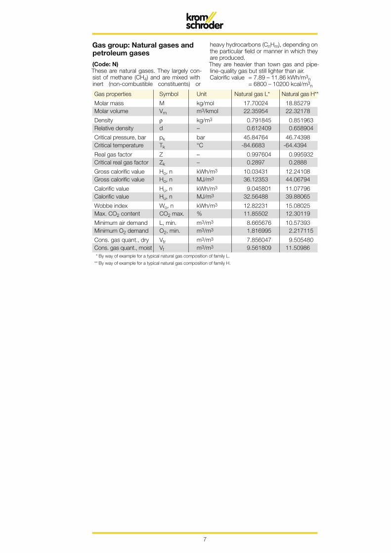
Gas group: Natural gases and petroleum gases
(Code: N)These are natural gases. They largely con-sist of methane (CH4) and are mixed with inert (non-combustible constituents) or
heavy hydrocarbons (CnHm), depending on the particular field or manner in which they are produced.They are heavier than town gas and pipe-line-quality gas but still lighter than air.Calorific value = 7.89 – 11.86 kWh/m3n = 6800 – 10200 kcal/m3n
Gas properties Symbol Unit Natural gas L* Natural gas H**
Molar mass M kg/mol 17.70024 18.85279Molar volume Vm m3/kmol 22.35954 22.32178
Density ρ kg/m3 0.791845 0.851963Relative density d – 0.612409 0.658904
Critical pressure, bar pk bar 45.84764 46.74398Critical temperature Tk °C -84.6683 -64.4394
Real gas factor Z – 0.997604 0.995932Critical real gas factor Zk – 0.2897 0.2888
Gross calorific value Ho, n kWh/m3 10.03431 12.24108Gross calorific value Ho, n MJ/m3 36.12353 44.06794
Calorific value Hu, n kWh/m3 9.045801 11.07796Calorific value Hu, n MJ/m3 32.56488 39.88065
Wobbe index Wo, n kWh/m3 12.82231 15.08025Max. CO2 content CO2 max. % 11.85502 12.30119
Minimum air demand L, min. m3/m3 8.665676 10.57393Minimum O2 demand O2, min. m3/m3 1.816995 2.217115
Cons. gas quant., dry Vtr m3/m3 7.856047 9.505480Cons. gas quant., moist Vf m3/m3 9.561809 11.50986
* By way of example for a typical natural gas composition of family L.
** By way of example for a typical natural gas composition of family H.
8
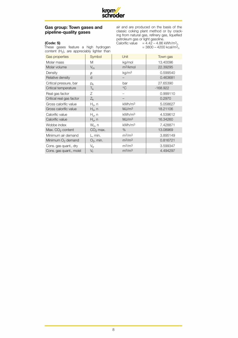
Gas group: Town gases and pipeline-quality gases
(Code: S)These gases feature a high hydrogen content (H2), are appreciably lighter than
air and are produced on the basis of the classic coking plant method or by crack-ing from natural gas, refinery gas, liquefied petroleum gas or light gasoline. Calorific value = 4.42 – 4.86 kWh/m3n = 3800 – 4200 kcal/m3n
Gas properties Symbol Unit Town gas
Molar mass M kg/mol 13.40096Molar volume Vm m3/kmol 22.39295
Density ρ kg/m3 0.599540Relative density d – 0.463681
Critical pressure, bar pk bar 27.65390Critical temperature Tk °C -168.922
Real gas factor Z – 0.999110Critical real gas factor Zk – 0.2970
Gross calorific value Ho, n kWh/m3 5.058627Gross calorific value Ho, n MJ/m3 18.21106
Calorific value Hu, n kWh/m3 4.539612Calorific value Hu, n MJ/m3 16.34260
Wobbe index Wo, n kWh/m3 7.428871Max. CO2 content CO2 max. % 13.08969
Minimum air demand L, min. m3/m3 3.895149Minimum O2 demand O2, min. m3/m3 0.816721
Cons. gas quant., dry Vtr m3/m3 3.599347Cons. gas quant., moist Vf m3/m3 4.494297
9
Gas properties Symbol Unit Propane Butane
Molar mass M kg/mol 44.0960 58.1230Molar volume Vm m3/kmol 21.9274 21.461
Density ρ kg/m3 2.0109 2.7080Relative density d – 1.5550 2.0940
Critical pressure, bar pk bar 42.400 38.0Critical temperature Tk °C 96.65 152.05
Real gas factor Z – 0.9783 0.9575Critical real gas factor Zk – 0.2770 0.2740
Gross calorific value Ho, n kWh/m3 28.1228 37.2392Gross calorific value Ho, n MJ/m3 101.2421 134.0611
Calorific value Hu, n kWh/m3 25.8931 34.3917Calorific value Hu, n MJ/m3 93.2152 123.8101
Wobbe index Wo, n kWh/m3 22.5524 25.7343Max. CO2 content CO2 max. % 13.7825 14.0857
Minimum air demand L, min. m3/m3 24.3515 32.3413Minimum O2 demand O2, min. m3/m3 5.1060 6.7813
Cons. gas quant., dry Vtr m3/m3 22.2930 29.711Cons. gas quant., moist Vf m3/m3 26.1411 34.6252
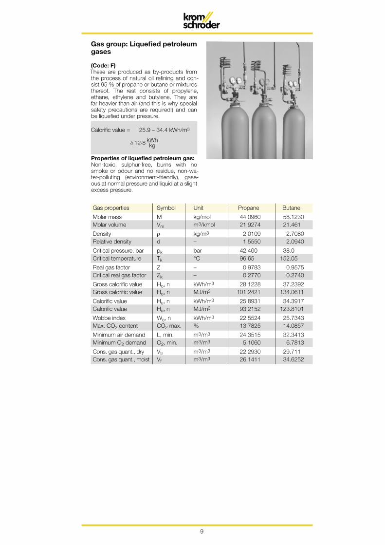
Gas group: Liquefied petroleum gases
(Code: F)These are produced as by-products from the process of natural oil refining and con-sist 95 % of propane or butane or mixtures thereof. The rest consists of propylene, ethane, ethylene and butylene. They are far heavier than air (and this is why special safety precautions are required!) and can be liquefied under pressure.
Calorific value = 25.9 – 34.4 kWh/m3
Properties of liquefied petroleum gas:Non-toxic, sulphur-free, burns with no smoke or odour and no residue, non-wa-ter-polluting (environment-friendly), gase-ous at normal pressure and liquid at a slight excess pressure.
10
Fuel
C
hem
ical
sym
bol
Com
bust
ion
form
ula
Uni
t of m
eas-
Cal
orifi
c va
lue
per
Flue
gas
com
posi
tion
Uni
t of h
eat
Bul
k de
nsity
R
emar
ks
ur
emen
t un
it of
mea
sure
men
t
io
Fuel
kc
al
kWh
CO
2/%
H
2O/%
N
2/%
kc
al/m
3 (n
) kW
h/m
3 (n
) kg
/Nm
3
Car
bon
C
C +
O2
= C
O2
kg
7935
9.
23
20.9
–
79.1
88
9 1.
034
–
C +
0.5
O2
= C
O
kg
2300
2.
67
34.6
(CO
) –
65.4
42
6 0.
495
–
Car
bon
mon
oxid
e C
O
CO
+ 0
.5 O
2 =
CO
2 N
m3
3020
3.
51
34.6
–
65.4
10
44
1.21
4 1.
250
Hyd
roge
n H
2 H
2 +
0.5
O2
= H
2O D
ampf
kg
28
700
33.3
7 –
34.6
65
.4
889
1.03
4 0.
0899
H2
+ 0
.5 O
2 =
H2O
Dam
pf
Nm
3 25
70
2.99
–
34.6
65
.4
889
1.03
4 –
Met
hane
C
H4
CH
4 +
2.0
O2
= C
O2
+ 2
H2O
N
m3
8560
9.
95
9.5
18.9
71
.6
810
0.94
2 0.
717
Etha
ne
CH
4 C
2H6
+ 3
.5 O
2 =
2 C
O2
+ 3
H2O
N
m3
1537
0 17
.87
11.0
16
.4
72.6
84
1 0.
978
1.35
6
Pro
pane
C
3H8
C3H
8 +
5.0
O2
= 3
CO
2 +
4 H
2O
Nm
3 22
350
25.9
9 11
.6
15.4
73
.0
862
1.00
2 2.
004
But
ane
C4H
10
C4H
10 +
6.5
O2
= 4
CO
2 +
5 H
2O
Nm
3 29
280
34.0
5 11
.9
14.9
73
.2
870
1.01
2 2.
703
Ethy
lene
C
2H4
C2H
4 +
3.0
O2
= 2
CO
2 +
2 H
2O
Nm
3 14
320
16.5
5 13
.0
13.0
74
.0
931
1.08
3 1.
261
Pro
pyle
ne
C3H
6 C
3H6
+ 4
.5 O
2 =
3 C
O2
+ 3
H2O
N
m3
2107
0 24
.50
13.0
13
.0
74.0
91
4 1.
063
1.91
5
But
ylen
e C
4H8
C4H
8 +
6.0
O2
= 4
CO
2 +
4 H
2O
Nm
3 27
190
31.6
2 13
.0
13.0
74
.0
885
1.02
9 –
Ace
tyle
ne
C2H
2 C
2H2
+ 2
.5 O
2 =
2 C
O2
+ H
2O
Nm
3 13
600
15.8
1 16
.1
8.0
75.9
10
90
1.26
7 1.
171
Ben
zole
C
6H6
C6H
6 +
7.5
O2
= 6
CO
2 +
3 H
2O
Nm
3 33
870
39.3
8 16
.1
8.0
75.9
90
5 1.
052
–
Hea
vy h
ydro
carb
ons
in
S
KW
+ 3
.76
O2
= 2
.45
CO
2 +
2.4
5 H
2O
” 17
000
19.7
7 13
.0
13.0
74
.0
905
1.05
2 1.
53
Hea
vy h
ydro
carb
ons
coke
-ove
n ga
s S
KW
+ 3
.34
O2
= 2
.17
CO
2 +
2.3
4 H
2O
” 15
900
18.4
9 12
.7
13.6
73
.7
927
1.07
8 1.
37
Sul
phur
S
S
+ O
2 =
SO
2 kg
22
22
2.58
20
.0 (S
O2)
–
79.1
66
5 0.
773
–
Hyd
roge
n su
lphi
de
H2S
H
2S +
1.5
O2
= H
2O +
SO
2 kg
36
30
4.22
14
.0 (S
O2)
14
.0
72.0
71
7 0.
834
1.53
9
Co
mb
usti
on
of
bas
ic c
ons
titu
ents
of
gas
es
11
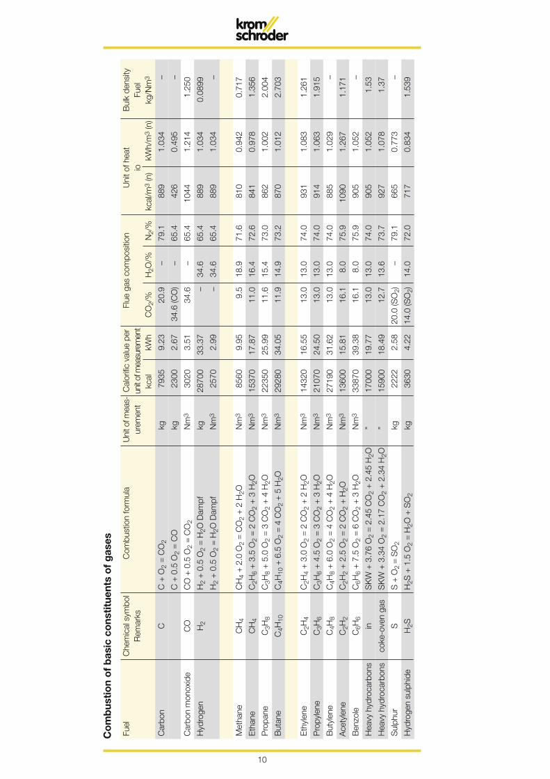
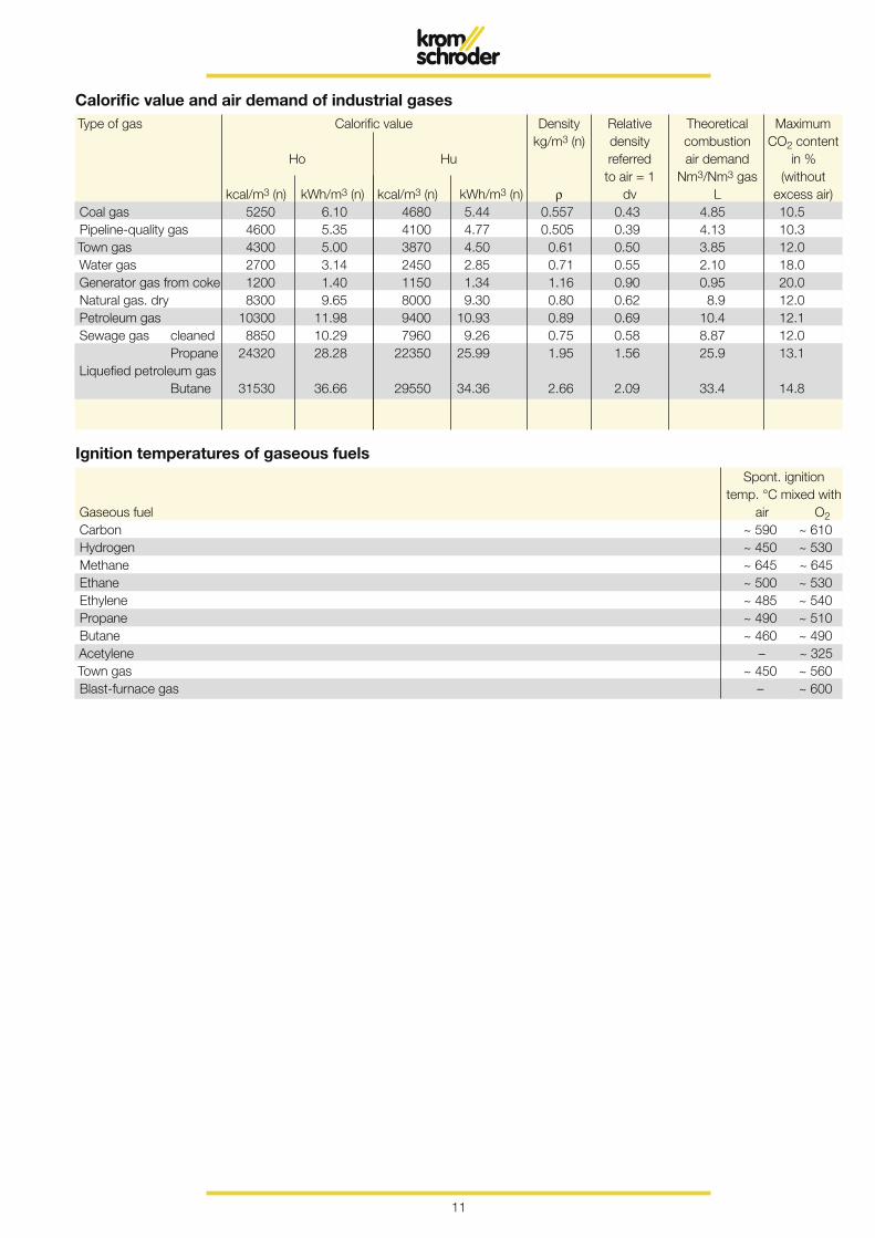
Calorific value and air demand of industrial gasesType of gas Calorific value Density Relative Theoretical Maximum kg/m3 (n) density combustion CO2 content Ho Hu referred air demand in % to air = 1 Nm3/Nm3 gas (without kcal/m3 (n) kWh/m3 (n) kcal/m3 (n) kWh/m3 (n) ρ dv L excess air)Coal gas 5250 6.10 4680 5.44 0.557 0.43 4.85 10.5Pipeline-quality gas 4600 5.35 4100 4.77 0.505 0.39 4.13 10.3Town gas 4300 5.00 3870 4.50 0.61 0.50 3.85 12.0Water gas 2700 3.14 2450 2.85 0.71 0.55 2.10 18.0Generator gas from coke 1200 1.40 1150 1.34 1.16 0.90 0.95 20.0Natural gas. dry 8300 9.65 8000 9.30 0.80 0.62 8.9 12.0Petroleum gas 10300 11.98 9400 10.93 0.89 0.69 10.4 12.1Sewage gas cleaned 8850 10.29 7960 9.26 0.75 0.58 8.87 12.0 Propane 24320 28.28 22350 25.99 1.95 1.56 25.9 13.1Liquefied petroleum gas Butane 31530 36.66 29550 34.36 2.66 2.09 33.4 14.8
Spont. ignition temp. °C mixed withGaseous fuel air O2Carbon ~ 590 ~ 610Hydrogen ~ 450 ~ 530Methane ~ 645 ~ 645Ethane ~ 500 ~ 530Ethylene ~ 485 ~ 540Propane ~ 490 ~ 510Butane ~ 460 ~ 490Acetylene – ~ 325Town gas ~ 450 ~ 560Blast-furnace gas – ~ 600
Ignition temperatures of gaseous fuels
12
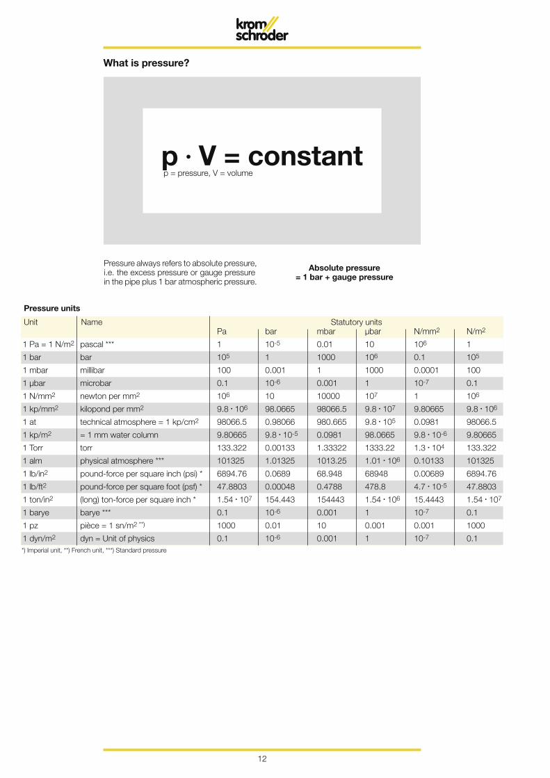
What is pressure?
p • V = constantp = pressure, V = volume
Pressure always refers to absolute pressure, i.e. the excess pressure or gauge pressure in the pipe plus 1 bar atmospheric pressure.
Absolute pressure = 1 bar + gauge pressure
Pressure units
Unit Name Statutory units Pa bar mbar µbar N/mm2 N/m2
1 Pa = 1 N/m2 pascal *** 1 10-5 0.01 10 106 1
1 bar bar 105 1 1000 106 0.1 105
1 mbar millibar 100 0.001 1 1000 0.0001 100
1 µbar microbar 0.1 10-6 0.001 1 10-7 0.1
1 N/mm2 newton per mm2 106 10 10000 107 1 106
1 kp/mm2 kilopond per mm2 9.8 • 106 98.0665 98066.5 9.8 • 107 9.80665 9.8 • 106
1 at technical atmosphere = 1 kp/cm2 98066.5 0.98066 980.665 9.8 • 105 0.0981 98066.5
1 kp/m2 = 1 mm water column 9.80665 9.8 • 10-5 0.0981 98.0665 9.8 • 10-6 9.80665
1 Torr torr 133.322 0.00133 1.33322 1333.22 1.3 • 104 133.322
1 alm physical atmosphere *** 101325 1.01325 1013.25 1.01 • 106 0.10133 101325
1 lb/in2 pound-force per square inch (psi) * 6894.76 0.0689 68.948 68948 0.00689 6894.76
1 lb/ft2 pound-force per square foot (psf) * 47.8803 0.00048 0.4788 478.8 4.7 • 10-5 47.8803
1 ton/in2 (long) ton-force per square inch * 1.54 • 107 154.443 154443 1.54 • 106 15.4443 1.54 • 107
1 barye barye *** 0.1 10-6 0.001 1 10-7 0.1
1 pz pièce = 1 sn/m2 **) 1000 0.01 10 0.001 0.001 1000
1 dyn/m2 dyn = Unit of physics 0.1 10-6 0.001 1 10-7 0.1*) Imperial unit, **) French unit, ***) Standard pressure

13
m3 (n)
kW/m3 (n)
... it’s me that you have to calculate with
... it’s me to which one refers… it’s only me for which you have to pay… you should never forget me
p = pressureV = volumeT = temperature
This cube contains 1000 m3 of gas at nor-mal atmospheric pressure, i.e. 1 bar abso-lute.
ImportantWe shall now increase the pressure to 1 bar gauge pressure or 2 bar absolute. The volume has been reduced by 50 %.
Here, the gauge pressure has risen to 2 bar. The volume has shrunk to 1/3.
At 3 bar, the volume shrinks to only 1/4 of the original volume.
We reach a figure of 1/5 or 20 % at 4 bar.
At 9 bar gauge pressure = 10 bar absolute, only 1/10 of the original volume remains.
Hello!I am a standard cubic metre. I know only one law. I possess true energy.
p • v = const. T

14
V•
= A • v
v = 18 ms
Volume is the contents of a hollow body, e.g. tanks, pipes, chambers or even gas appliances.
You should not confuse volume with quan-tity.
If a specific quantity of gas (or air) flows through pipes or equipment, we speak of
Flow rate is volume per unit of time, e.g. m3/h or l/min. Flow rate = V
•
Flow rate = cross-sectional area of the pipe x velocity
Using the diagram, it is possible to determine the flow velocity at a given flow rate and pipe diameter.
Example:Flow rate = 100 m3/hPipe diameter = DN 40Flow velocity read off:
The flow velocity is not dependent on the density of the medium.
100 m3/h of natural gas at DN 40 = 18 ms100 m3/h of water at DN 40 = 18 ms
p • V = constantp = pressure, V = volume
What are volume, flow rate and flow velocity?
flow rate
volumetime or also V
•
=
15
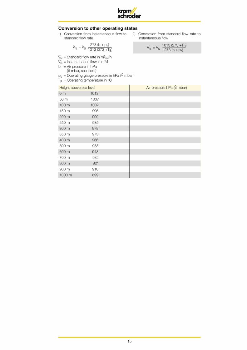
V. N = Standard flow rate in m3(n)/hV. B = Instantaneous flow in m3/h b = Air pressure in hPa
(= mbar, see table)pe = Operating gauge pressure in hPa (= mbar)TB = Operating temperature in °C
Conversion to other operating states1) Conversion from instantaneous flow to
standard flow rate2) Conversion from standard flow rate to
instantaneous flow
Height above sea level Air pressure hPa (= mbar)
0 m 1013
50 m 1007
100 m 1002
150 m 996
200 m 990
250 m 985
300 m 978
350 m 973
400 m 966
500 m 955
600 m 943
700 m 932
800 m 921
900 m 910
1000 m 899

16
°C K °F °R
1 °C 1 273.16 33.8 493.48
1 K -273.16 1 -239.36 1.8
1 °F -17.22 255.93 1 460.67
1 °R -272.6 1.8 -458.67 1
200 °C 473 K
-100 °C 173 K
-162 °C
-200 °C 73 K
273 °C 0 K
100 °C 373 K
0 °C 273 K
-
+
+
°C = 5/9 (°F - 32) = K - 273.16K = 273.16 + °C = 5/9 °R
°F = 1.8 °C • 32 = °R - 459.67°R = 459.67 + °F = 1.8 K
What is temperature?
Temperature is a measure of the energy state of a body.
Celsius temperature (t)
Thermodynamic temperature (T)
Temperature difference (T, t)
The basic unit used is Kelvin [K]. The defini-tion of Kelvin is based on the simultaneous vaporous, liquid and solid state of water which is at around 0.01 °C (triple point).Starting from this point, the volume of a gas is reduced by one 273.16th with a temper-ature reduction of 1 K.Consequently, the volume with a tempera-ture reduction of 273.16 may become equal to zero. This point was defined as absolute
zero and serves as the starting point for the thermodynamic temperature scale at 0 K.The Celsius temperature scale which is normally used can also continue to be used. Starting from the freezing point and boiling point of water, the scale is split into 100 equal parts. 0 °C is freezing point and 100 °C is boiling point.The subdivision of the scale means that one degree Celsius as a temperature difference is equal to 1 Kelvin temperature difference. All materials whose temperature lies above –273 °C contain energy which can be uti-lised in certain areas.
Freezing point, the starting point for the Celsius scale
At this temperature, natural gas becomes liquid and is transported or stored.
17
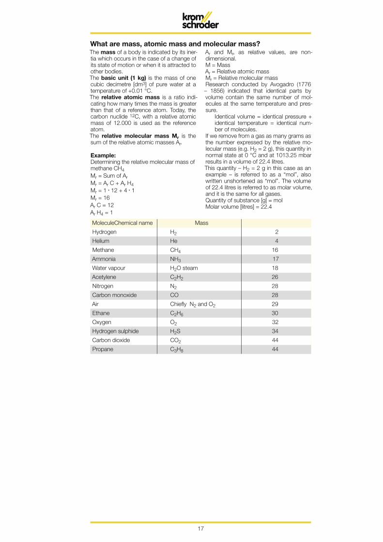
The mass of a body is indicated by its iner-tia which occurs in the case of a change of its state of motion or when it is attracted to other bodies. The basic unit (1 kg) is the mass of one cubic decimetre [dm3] of pure water at a temperature of +0.01 °C.The relative atomic mass is a ratio indi-cating how many times the mass is greater than that of a reference atom. Today, the carbon nuclide 12C, with a relative atomic mass of 12.000 is used as the reference atom.The relative molecular mass Mr is the sum of the relative atomic masses Ar.
Example: Determining the relative molecular mass of methane CH4Mr = Sum of ArMr = Ar C + Ar H4Mr = 1 • 12 + 4 • 1Mr = 16Ar C = 12Ar H4 = 1
Ar and Mr, as relative values, are non- dimensional.M = MassAr = Relative atomic massMr = Relative molecular massResearch conducted by Avogadro (1776 – 1856) indicated that identical parts by volume contain the same number of mol-ecules at the same temperature and pres-sure.
Identical volume = identical pressure + identical temperature = identical num-ber of molecules.
If we remove from a gas as many grams as the number expressed by the relative mo-lecular mass (e.g. H2 = 2 g), this quantity in normal state at 0 °C and at 1013.25 mbar results in a volume of 22.4 litres.This quantity – H2 = 2 g in this case as an example – is referred to as a “mol”, also written unshortened as “mol”. The volume of 22.4 litres is referred to as molar volume, and it is the same for all gases.Quantity of substance [g] = molMolar volume [litres] = 22.4
What are mass, atomic mass and molecular mass?
Molecule Chemical name Mass
Hydrogen H2 2
Helium He 4
Methane CH4 16
Ammonia NH3 17
Water vapour H2O steam 18
Acetylene C2H2 26
Nitrogen N2 28
Carbon monoxide CO 28
Air Chiefly N2 and O2 29
Ethane C2H6 30
Oxygen O2 32
Hydrogen sulphide H2S 34
Carbon dioxide CO2 44
Propane C3H8 44
18
J kJ kWh kcal kpm
1 J 1 0.001 2.78 . 10-7 2.39 . 10-4 0.10197
1 kJ 1000 1 2.78 . 10-4 0.239 101.97
1 kWh 3.6 . 106 3600 1 860 3.67 . 105
1 kcal 4186.8 4.1868 1.163 . 10-3 1 426.93
1 kpm 9.8067 9.8067 . 10-3 2.72 . 10-6 2.34 . 10-3 1
14,4 °C
15,5 °C
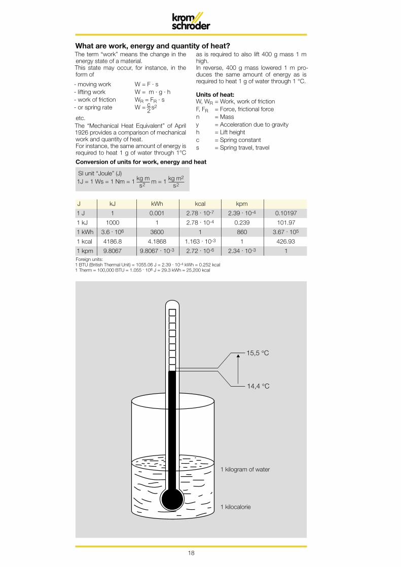
What are work, energy and quantity of heat?
Conversion of units for work, energy and heat
Foreign units:1 BTU (British Thermal Unit) = 1055.06 J = 2.39 . 10-4 kWh = 0.252 kcal1 Therm = 100,000 BTU = 1.055 . 108 J = 29.3 kWh = 25,200 kcal
1 kilogram of water
1 kilocalorie
The term “work” means the change in the energy state of a material.This state may occur, for instance, in the form of
- moving work W = F · s- lifting work W = m · g · h- work of friction WR = FR · s- or spring rate W = c 2 s
2
etc. The “Mechanical Heat Equivalent” of April 1926 provides a comparison of mechanical work and quantity of heat.For instance, the same amount of energy is required to heat 1 g of water through 1°C
as is required to also lift 400 g mass 1 m high.In reverse, 400 g mass lowered 1 m pro-duces the same amount of energy as is required to heat 1 g of water through 1 °C. Units of heat:W, WR = Work, work of frictionF, FR = Force, frictional forcen = Massy = Acceleration due to gravityh = Lift heightc = Spring constants = Spring travel, travel
SI unit “Joule” (J)
19
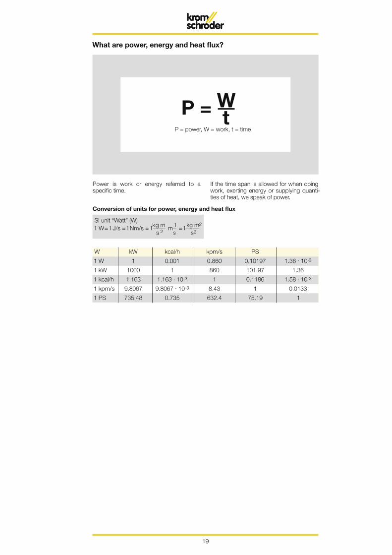
P = W t
What are power, energy and heat flux?
Power is work or energy referred to a specific time.
If the time span is allowed for when doing work, exerting energy or supplying quanti-ties of heat, we speak of power.
Conversion of units for power, energy and heat flux
P = power, W = work, t = time
SI unit “Watt” (W)
W kW kcal/h kpm/s PS
1 W 1 0.001 0.860 0.10197 1.36 . 10-3
1 kW 1000 1 860 101.97 1.36
1 kcal/h 1.163 1.163 . 10-3 1 0.1186 1.58 . 10-3
1 kpm/s 9.8067 9.8067 . 10-3 8.43 1 0.0133
1 PS 735.48 0.735 632.4 75.19 1

20
T 0 °C P 1,013 bar
T 0 °C P 1,013 bar
T 0 °C P 1,013 barThe term density means the quotient of the mass of a substance divided by the volume.
What are density and relative density?
ρ, ρ(n) = Density, normal densityM = MassV = Volumedv = Density ratioMr = Molecular mass
In addition, the density of a substance can be determined on the basis of its relative molecular mass Mr and on the basis of mo-lar volume of 22.4 m3.Since the molar volume refers to the stand-ard state, we thus obtain the molar den-sity.
The term density ratio dv of a gas means the ratio of its density to that of air in the same state conditions.
Density ratio:dv <1 = lighter than airdv >1 = heavier than air
density of the gas (in normal state)density of the air 1.293 kg/m3 (in normal state)
21
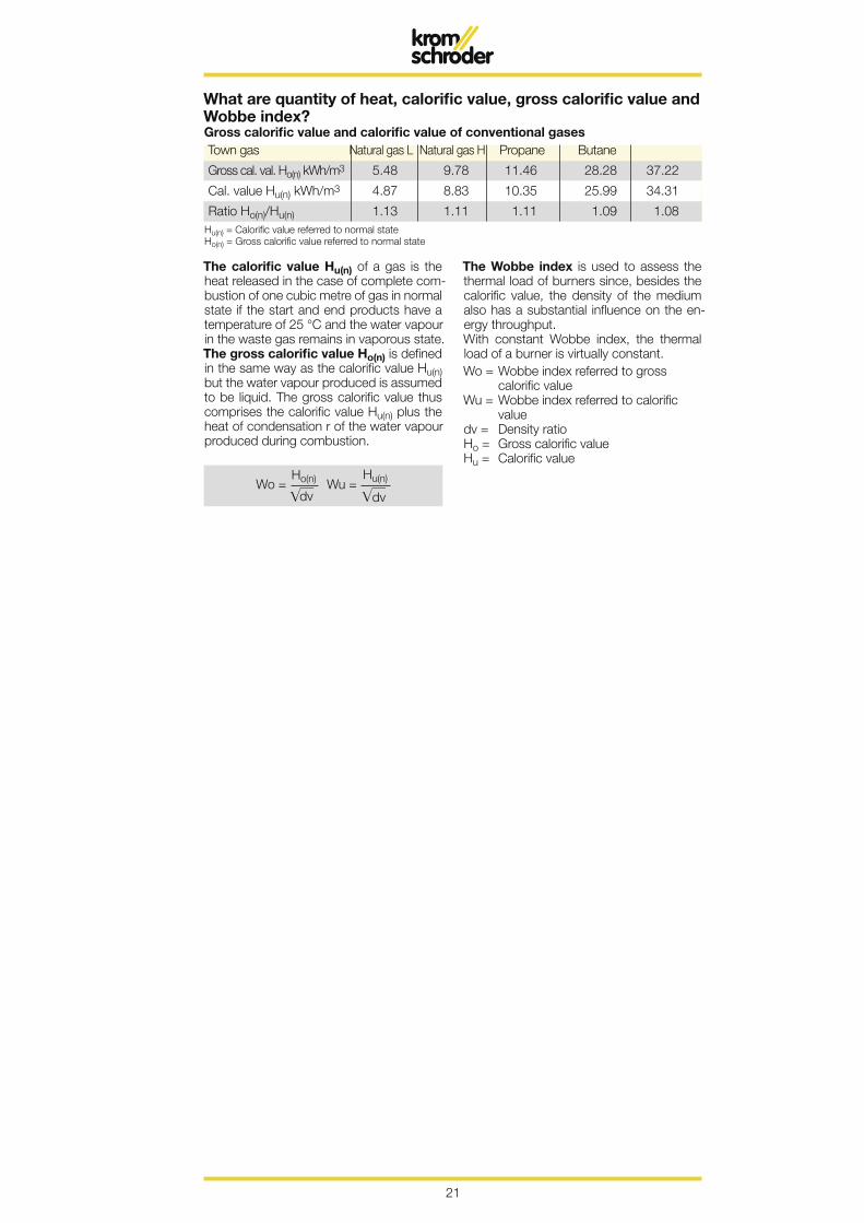
What are quantity of heat, calorific value, gross calorific value and Wobbe index?
Town gas Natural gas L Natural gas H Propane Butane
Gross cal. val. Ho(n) kWh/m3 5.48 9.78 11.46 28.28 37.22
Cal. value Hu(n) kWh/m3 4.87 8.83 10.35 25.99 34.31
Ratio Ho(n)/Hu(n) 1.13 1.11 1.11 1.09 1.08
Gross calorific value and calorific value of conventional gases
Hu(n) = Calorific value referred to normal stateHo(n) = Gross calorific value referred to normal state
The calorific value Hu(n) of a gas is the heat released in the case of complete com-bustion of one cubic metre of gas in normal state if the start and end products have a temperature of 25 °C and the water vapour in the waste gas remains in vaporous state. The gross calorific value Ho(n) is defined in the same way as the calorific value Hu(n) but the water vapour produced is assumed to be liquid. The gross calorific value thus comprises the calorific value Hu(n) plus the heat of condensation r of the water vapour produced during combustion.
The Wobbe index is used to assess the thermal load of burners since, besides the calorific value, the density of the medium also has a substantial influence on the en-ergy throughput.With constant Wobbe index, the thermal load of a burner is virtually constant.Wo = Wobbe index referred to gross calorific valueWu = Wobbe index referred to calorific valuedv = Density ratioHo = Gross calorific value Hu = Calorific value
22
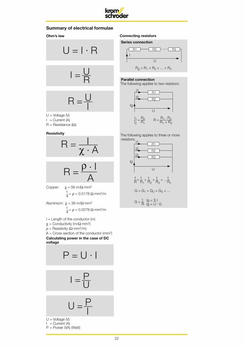
U = I . R
I = U R
R = U I
P = U . I
I = P U
U = P I
R1 R2 R3
U
I
Rg = R1 + R2 + ... + Rn
R2
UIg
R1I1
I2
R2
U
Ig
R1I1
I2
R3I3
G = G1 + G2 + G3 + ...
Summary of electrical formulae
Ohm’s law Connecting resistors
Series connection
U = Voltage (V)I = Current (A)R = Resistance (Ω)
Copper: χ = 56 m/Ω mm2
1 χ = ρ = 0.0178 Ω mm2/m
Aluminium: χ = 36 m/Ω mm2 1 χ = ρ = 0.0278 Ω mm2/m
I = Length of the conductor (m)χ = Conductivity (m/Ω mm2) ρ = Resistivity (Ω mm2/m)A = Cross-section of the conductor (mm2)
Resistivity
Calculating power in the case of DC voltage
U = Voltage (V) I = Current (A) P = Power (VA) (Watt)
Parallel connectionThe following applies to two resistors:
The following applies to three or more resistors:

23
XI = ω . L ω = 2 . π . f
ω = 2 . π . f
Summary of electrical formulae
Voltage drop Direct current
Resistances in the alternating current circuit
Inductive reactance
XL = Inductive reactance (Ω)L = Inductance (H)I = Current (A)ω, f = Angular frequency, frequency (1/s)
Capacitive reactance
Uv = Voltage drop (V)U = Mains voltage (V)A = Cross-section (mm2)I = Total current (A)P = Total power (W)l = Length of the conductor (m)χ = Conductivity (m/Ω mm2/m)
XC = Capacitive reactance (Ω)L = Capacitance (F)I = Current (A)ω, f = Angular frequency, frequency (1/s)
Three-phase current
Alternating current

24
I = Is . sin ω t
U = Us . sin ω t
ω = 2 . π t
f = 1 t
t = 1f
U, I
0° 180° 360°
Us, Ist
U
0° 180° 360°
Us
t
U
0° 180° 360°
Us
t
U Us
0° 180° 360°t
U Us+
Us-t1
t2
Summary of electrical formulae
Various values of sinusoidal quantities
Three-phase rectifierHalf-wave rectifier
Full-wave rectifier
I, U = Instantaneous values (A, V)Is, Us = Peak values (A, V)Irms, Urms = RMS values (A, V)Iar, Uar = Arithmetic mean values (A, V)f = Frequency (1/s)ω = Angular frequency (1/s)t = Period
Uar = 0.827 . Us
Urms = 0.841 . Us
Uar = 0.318 . US
Urms = 0.5 . Us
Uar = 0.637 . Us
Urms = 0.707 . Us rms
lar = 0.637 . ls
rms
rms
Uar = 0.637 . Us
25
R
L
R
C
T = LR
T = R . C
i = I . (1 - e - tT )
i = I . e - tT )
i = I . e - tT
u = U . (1 - e - tT )
u = U . e - tT
UXC
UR, UW
U
UR
I Iϕ
ϕϕ
S P P S
QC Ql
ϕ
Il, IBIC
IR IR, IW
I I
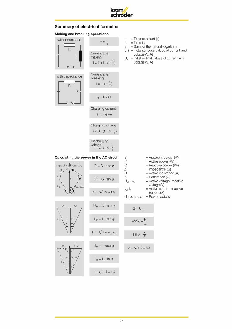
S = U . I
cos ϕ = R Z
sin ϕ = X Z
Z = R2 + X2
P = S . cos ϕ
Q = S . sin ϕ
S = P2 + Q2
Uw = U . cos ϕ
Ub = U . sin ϕ
U = U2 + U2b
Iw = I . cos ϕ
Ib = I . sin ϕ
I = Iw2 + Ib2
Summary of electrical formulae
Making and breaking operations
T = Time constant (s)t = Time (s)e = Base of the natural logarithmu, i = Instantaneous values of current and
voltage (V, A)U, I = Initial or final values of current and
voltage (V, A)
Calculating the power in the AC circuit S = Apparent power (VA)P = Active power (W)Q = Reactive power (VA)Z = Impedance (Ω)R = Active resistance (Ω)X = Reactance (Ω)Uw, Ub = Active voltage, reactive
voltage (V)lw, Ib = Active current, reactive
current (A)sin ϕ, cos ϕ = Power factors
with inductance
with capacitance
Current after making
Current after breaking
capacitive inductive
Charging current
Charging voltage
Discharging voltage

26
P1 = U . I . η [W]
P1 = U . I cos ϕ . η [W]
P1 = 1.73 . U . I cos ϕ . η [A]
Summary of electrical formulaeElectrical power (output) of motors
Direct currentPower generated Current consumption
Single-phase alternating currentPower generated Current consumption
Three-phase currentPower generated Current consumption
P1 = Mechanical power generated at the shaft of the motor in accordance with the rating plateP2 = Electrical power consumed
Three-phase currentEfficiency Current consumption
P = Active power (W)U = Voltage (V)I = Current (A)cos ϕ = Power factorη = Efficiency
Transformer
ü = Transformation ratioU1 = Input voltage in VU2 = Output voltage in VI1 = Input current in AI2 = Output current in AN1 = Number of turns of the input windingN2 = Number of turns of the output windingZ1 = Input-circuit AC resistance or impe-
dance in ΩZ2 = Output-circuit AC resistance or impe-
dance in Ω
Duty type:Continuous duty or intermittent dutyIn the case of the latter, the following ap-plies:Duty ratio15 %, 20 %, 33 %, duty(27 s, 36 s, 59 s in 3 min)
or continuous duty.
Duty ratio
Transformer

27
28
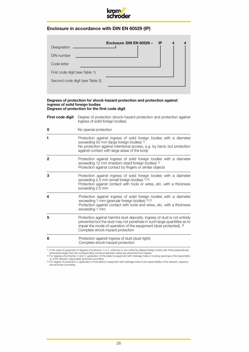
Enclosure DIN EN 60529 – IP 4 4Designation
DIN number
Code letter
First code digit (see Table 1)
Second code digit (see Table 2)
Enclosure in accordance with DIN EN 60529 (IP)
Degrees of protection for shock-hazard protection and protection against ingress of solid foreign bodiesDegrees of protection for the first code digit
First code digit Degree of protection (shock-hazard protection and protection against ingress of solid foreign bodies)
0 No special protection
1 Protection against ingress of solid foreign bodies with a diameter exceeding 50 mm (large foreign bodies) 1)
No protection against intentional access, e.g. by hand, but protection against contact with large areas of the body
2 Protection against ingress of solid foreign bodies with a diameter exceeding 12 mm (medium-sized foreign bodies) 1)
Protection against contact by fingers or similar objects
3 Protection against ingress of solid foreign bodies with a diameter exceeding 2.5 mm (small foreign bodies) 1) 2)
Protection against contact with tools or wires, etc. with a thickness exceeding 2.5 mm
4 Protection against ingress of solid foreign bodies with a diameter exceeding 1 mm (granular foreign bodies) 1) 2)
Protection against contact with tools and wires, etc. with a thickness exceeding 1 mm
5 Protection against harmful dust deposits. Ingress of dust is not entirely prevented but the dust may not penetrate in such large quantities as to impair the mode of operation of the equipment (dust-protected). 3)
Complete shock-hazard protection
6 Protection against ingress of dust (dust-tight) Complete shock-hazard protection
1) In the case of equipment of degrees of protection 1 to 4, uniformly or non-uniformly shaped foreign bodies with three perpendicular dimensions larger than the corresponding numerical diameter values are prevented from ingress.
2) For degrees of protection 3 and 4, application of this table to equipment with drainage holes or cooling openings is the responsibili-ty of the relevant, responsible technical committee.
3) For degree of protection 5, application of this table to equipment with drainage holes is the responsibility of the relevant, responsi-ble technical committee.

29
Enclosure in accordance with DIN EN 60529 (IP)Degrees of protection for protection against ingress of waterDegrees of protection for the second code digit
Second code digit Degree of protection (protection against ingress of water)
0 No special protection
1 Protection against dripping water falling vertically. It may not have a harmful effect (drip water).
2 Protection against dripping water falling perpendicularly. It may not have a harmful effect in the case of equipment (housing)
inclined up to 15° with respect to its normal position (obliquely inci-dent drip water).
3 Protection against water falling at any angle up to 60° with respect to the vertical.
It may not have a harmful effect (spray water).
4 Protection against water splashing from all directions against the equipment (housing).
It may not have a harmful effect (spray water).
5 Protection against a water jet from a nozzle aimed from all direc-tions against the equipment (housing).
It may not have a harmful effect (hose water).
6 Protection against heavy seas or strong water jets. Harmful quantities of water may not penetrate the equipment (hous-
ing) (conditions on ships’ decks).
7 Protection against water if the equipment (housing) is immersed in water under pressure and time conditions.
Harmful quantities of water may not penetrate (immersion).
8 The equipment (housing) is suitable for continuous submersion in water under conditions described by the manufacturer (submer-sion). 1)
1) This degree of protection normally means an air-tight sealed item of equipment. However, in the case of certain types of equipment, water may penetrate if it does not have a harmful effect.

30
r
r
h h 1
P
a
d 1d 2d
27° 30'
90°
d
l1
H = 0.960 491 PH1 = 0.640 327 PR = 0.137 329 P
R
H H1
R
P
D1
D2
D
27° 30'
H 6H 6
h = 0.960 237 Ph1 = 0.640 327 Pr = 0.137 278 P
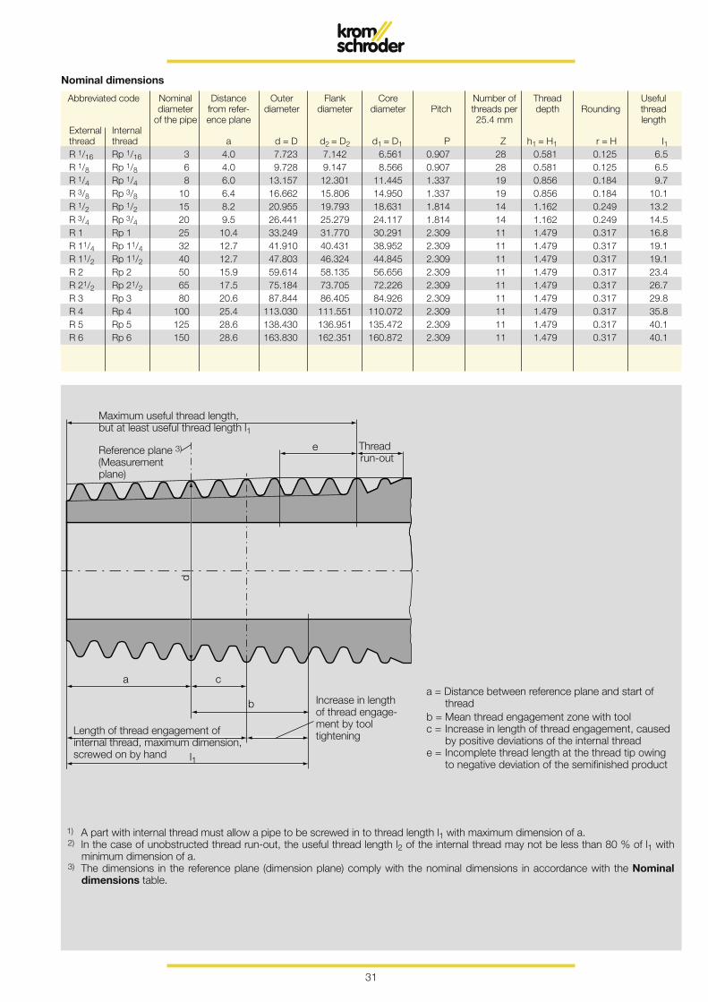
Whitworth pipe threads for threaded pipes and fittingsParallel internal thread and tapered external thread, thread dimensions
1 Field of applicationThis Standard applies to connections of parallel internal threads to valves, fittings and threaded flanges, etc. with tapered ex-ternal threads.
If necessary, a suitable sealant may be used in the thread in order to ensure a tight connection.
Dimensions in mm
2 Dimensions, designations
2.1 Parallel internal thread (abbreviated code Rp)
2.2 Tapered external thread (abbreviated code R) (taper 1 : 16)
The profile of the parallel internal thread complies with that in accordance with DIN ISO 228, Part 1.Designation of the parallel Whitworth pipe internal thread with abbreviated code Rp ½:Pipe thread ISO 7-1 – Rp ½
Designations of a tapered Whitworth pipe external thread with abbreviated code R ½:Pipe thread ISO 7-1 – R ½
Reference plane(Measuring orifice)
Reference plane(Measuring orifice)
Thread axis
31
e
d
a
l1
b
c
Abbreviated code Nominal Distance Outer Flank Core Number of Thread Useful diameter from refer- diameter diameter diameter Pitch threads per depth Rounding thread of the pipe ence plane 25.4 mm length External Internal thread thread a d = D d2 = D2 d1 = D1 P Z h1 = H1 r = H I1 R 1/16 Rp 1/16 3 4.0 7.723 7.142 6.561 0.907 28 0.581 0.125 6.5 R 1/8 Rp 1/8 6 4.0 9.728 9.147 8.566 0.907 28 0.581 0.125 6.5 R 1/4 Rp 1/4 8 6.0 13.157 12.301 11.445 1.337 19 0.856 0.184 9.7 R 3/8 Rp 3/8 10 6.4 16.662 15.806 14.950 1.337 19 0.856 0.184 10.1 R 1/2 Rp 1/2 15 8.2 20.955 19.793 18.631 1.814 14 1.162 0.249 13.2 R 3/4 Rp 3/4 20 9.5 26.441 25.279 24.117 1.814 14 1.162 0.249 14.5 R 1 Rp 1 25 10.4 33.249 31.770 30.291 2.309 11 1.479 0.317 16.8 R 11/4 Rp 11/4 32 12.7 41.910 40.431 38.952 2.309 11 1.479 0.317 19.1 R 11/2 Rp 11/2 40 12.7 47.803 46.324 44.845 2.309 11 1.479 0.317 19.1 R 2 Rp 2 50 15.9 59.614 58.135 56.656 2.309 11 1.479 0.317 23.4 R 21/2 Rp 21/2 65 17.5 75.184 73.705 72.226 2.309 11 1.479 0.317 26.7 R 3 Rp 3 80 20.6 87.844 86.405 84.926 2.309 11 1.479 0.317 29.8 R 4 Rp 4 100 25.4 113.030 111.551 110.072 2.309 11 1.479 0.317 35.8 R 5 Rp 5 125 28.6 138.430 136.951 135.472 2.309 11 1.479 0.317 40.1 R 6 Rp 6 150 28.6 163.830 162.351 160.872 2.309 11 1.479 0.317 40.1
Nominal dimensions
a = Distance between reference plane and start of threadb = Mean thread engagement zone with toolc = Increase in length of thread engagement, caused by positive deviations of the internal threade = Incomplete thread length at the thread tip owing to negative deviation of the semifinished product
1) A part with internal thread must allow a pipe to be screwed in to thread length l1 with maximum dimension of a.2) In the case of unobstructed thread run-out, the useful thread length l2 of the internal thread may not be less than 80 % of l1 with
minimum dimension of a.3) The dimensions in the reference plane (dimension plane) comply with the nominal dimensions in accordance with the Nominal
dimensions table.
Length of thread engagement of internal thread, maximum dimension, screwed on by hand
Increase in length of thread engage-ment by tool tightening
Maximum useful thread length, but at least useful thread length l1
Reference plane 3)
(Measurement plane)
Thread run-out
32
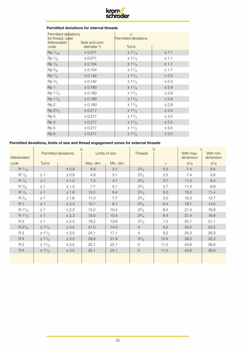
a b l1 Permitted deviations Limits of size Threads With max. With min. Abbreviated dimension dimension
code Turns Max. dim. Min. dim. ≈ of a of a
R 1/16 ± 0.9 4.9 3.1 23/4 2.5 7.4 5.6
R 1/8 ± 1 ± 0.9 4.9 3.1 23/4 2.5 7.4 5.6
R 1/4 ± 1 ± 1.3 7.3 4.7 23/4 3.7 11.0 8.4
R 3/8 ± 1 ± 1.3 7.7 5.1 23/4 3.7 11.4 8.8
R 1/2 ± 1 ± 1.8 10.0 6.4 23/4 5.0 15.0 11.4
R 3/4 ± 1 ± 1.8 11.3 7.7 23/4 5.0 16.3 12.7
R 1 ± 1 ± 2.3 12.7 8.1 23/4 6.4 19.1 14.5
R 11/4 ± 1 ± 2.3 15.0 10.4 23/4 6.4 21.4 16.8
R 11/2 ± 1 ± 2.3 15.0 10.4 23/4 6.4 21.4 16.8
R 2 ± 1 ± 2.3 18.2 13.6 31/4 7.5 25.7 21.1
R 21/2 ± 11/2 ± 3.5 21.0 14.0 4 9.2 30.2 23.2
R 3 ± 11/2 ± 3.5 24.1 17.1 4 9.2 33.3 26.3
R 4 ± 11/2 ± 3.5 28.9 21.9 31/2 10.4 39.3 32.3
R 5 ± 11/2 ± 3.5 32.1 25.1 5 11.5 43.6 36.6
R 6 ± 11/2 ± 3.5 32.1 25.1 5 11.5 43.6 36.6
Permitted deviations, limits of size and thread engagement zones for external threads
Permitted deviations c for thread, outer Permitted deviations Abbreviated flank and core code diameter 4) Turns
Rp 1/16 ± 0.071 ± 11/4 ± 1.1
Rp 1/8 ± 0.071 ± 11/4 ± 1.1
Rp 1/4 ± 0.104 ± 11/4 ± 1.7
Rp 3/8 ± 0.104 ± 11/4 ± 1.7
Rp 1/2 ± 0.142 ± 11/4 ± 2.3
Rp 3/4 ± 0.142 ± 11/4 ± 2.3
Rp 1 ± 0.180 ± 11/4 ± 2.9
Rp 11/4 ± 0.180 ± 11/4 ± 2.9
Rp 11/2 ± 0.180 ± 11/4 ± 2.9
Rp 2 ± 0.180 ± 11/4 ± 2.9
Rp 21/2 ± 0.217 ± 11/2 ± 3.5
Rp 3 ± 0.217 ± 11/2 ± 3.5
Rp 4 ± 0.217 ± 11/2 ± 3.5
Rp 5 ± 0.217 ± 11/2 ± 3.5
Rp 6 ± 0.217 ± 11/2 ± 3.5
Permitted deviations for internal threads

33
34
DNd2
Øk
d4
ØD
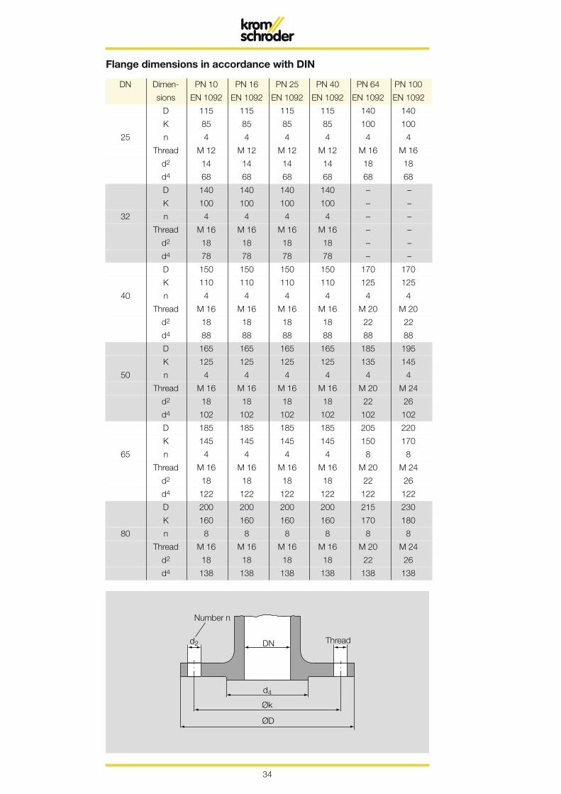
DN Dimen- PN 10 PN 16 PN 25 PN 40 PN 64 PN 100
sions EN 1092 EN 1092 EN 1092 EN 1092 EN 1092 EN 1092
D 115 115 115 115 140 140
K 85 85 85 85 100 100
25 n 4 4 4 4 4 4
Thread M 12 M 12 M 12 M 12 M 16 M 16
d2 14 14 14 14 18 18
d4 68 68 68 68 68 68
D 140 140 140 140 – –
K 100 100 100 100 – –
32 n 4 4 4 4 – –
Thread M 16 M 16 M 16 M 16 – –
d2 18 18 18 18 – –
d4 78 78 78 78 – –
D 150 150 150 150 170 170
K 110 110 110 110 125 125
40 n 4 4 4 4 4 4
Thread M 16 M 16 M 16 M 16 M 20 M 20
d2 18 18 18 18 22 22
d4 88 88 88 88 88 88
D 165 165 165 165 185 195
K 125 125 125 125 135 145
50 n 4 4 4 4 4 4
Thread M 16 M 16 M 16 M 16 M 20 M 24
d2 18 18 18 18 22 26
d4 102 102 102 102 102 102
D 185 185 185 185 205 220
K 145 145 145 145 150 170
65 n 4 4 4 4 8 8
Thread M 16 M 16 M 16 M 16 M 20 M 24
d2 18 18 18 18 22 26
d4 122 122 122 122 122 122
D 200 200 200 200 215 230
K 160 160 160 160 170 180
80 n 8 8 8 8 8 8
Thread M 16 M 16 M 16 M 16 M 20 M 24
d2 18 18 18 18 22 26
d4 138 138 138 138 138 138
Flange dimensions in accordance with DIN
Number n
Thread

35
1 1.6 2.5 4 6 10 16 25 40 63 100 160 250 400
The values entered in the table represent the PN graduation and refer to an operat-ing state at 20 °C. In the case of ferrous materials in accordance with the table in
DIN 2401, Sheet 2, the permitted operating pressure may also be applied up to 120 °C.
Pressure levels in accordance with DIN
DN Dimen- PN 10 PN 16 PN 25 PN 40 PN 64 PN 100
sions EN 1092 EN 1092 EN 1092 EN 1092 EN 1092 EN 1092
D 220 220 235 235 250 265
K 180 180 190 190 200 210
100 n 8 8 8 8 8 8
Thread M 16 M 16 M 20 M 20 M 24 M 27
d2 18 18 22 22 26 30
d4 158 158 162 162 162 162
D 250 250 270 270 295 315
K 210 210 220 220 240 250
125 n 8 8 8 8 8 8
Thread M 16 M 16 M 24 M 24 M 27 M 30
d2 18 18 26 26 30 33
d4 188 188 188 188 188 188
D 285 285 300 300 345 355
K 240 240 250 250 280 290
150 n 8 8 8 8 8 12
Thread M 20 M 20 M 24 M 24 M 30 M 30
d2 22 22 26 26 33 33
d4 212 212 218 218 218 218
D 340 340 360 375 415 430
K 295 295 310 320 345 360
200 n 8 12 12 12 12 12
Thread M 20 M 20 M 24 M 27 M 33 M 33
d2 22 22 26 30 36 36
d4 268 268 278 285 285 285
D 395 405 425 450 470 505
K 350 355 370 385 400 430
250 n 12 12 12 12 12 12
Thread M 20 M 20 M 27 M 30 M 33 M 36
d2 22 26 30 33 36 39
d4 320 320 335 345 345 345
D 445 460 485 515 530 585
K 400 410 430 450 460 500
300 n 12 12 16 16 16 16
Thread M 20 M 24 M 27 M 30 M 33 M 29
d2 22 26 30 33 36 42
d4 370 378 395 410 410 410
Flange dimensions in accordance with DIN

36
2
3
4
5
6
8
10
20
30
40
50
60
80
4 5 6 7 8 10 20 30 40 50 60 80 100 200 300 400
1
1 2 3 600 8001000 2000 3000 6000 10000
100
DN 6 (7
)
DN 8 (9
,9)
DN 10
(13,
6)DN 1
5 (1
7,3)
DN 20
(22,
3)DN 2
5 (2
8,5)
DN 32
(37,
2)
DN 40
(43,
1)DN 5
0 (5
4,5)
DN 65
(70,
3)DN 8
0 (8
2,5)
DN 100
(107
,1)
DN 125
(131
,7)
DN 150
(159
,3)
DN 200
(207
,3)
DN 250
(260
,4)
DN 300
(309
,7)
Flow velocities in pipes
Note: The inside diameter figures correspond to the most popular dimensions for gas pipes stipulated in Stand-ards DIN 2440 and DIN 2450. In the case of other cross-sections, the flow velocities will differ accordingly.
Flow rate V' [m3/h (n)]
Flow
vel
ocity
v in
m/s
Pipe inside diameter Ø [mm]
Nominal diameter DN

37
0,02
0,03
0,040,05
0,1
0,2
0,5
4 5 6 7 8 10 20 30 40 50 60 80 100 200 300 4001
5 6 7 8 10 20 30 40 50 60 80 100 200 300 4002
4 5 6 7 8 10 20 30 40 50 60 80 100 200 300 4004
4 5 6 7 8 10 20 30 40 50 60 80 100 200 3003
3
3
600
0,01
1 2 3
1 2 3 4
1 2
1 2
600 8001000
8001000
600 8001000
400 600
2000 3000
2000 3000
2000 3000
80 100 2000 3000
6000
6000 10000
10000
6000
6000
1
2
5
10
DN15
DN20
DN25
DN32
DN40
DN50
DN65
DN80
DN10
0DN
125
DN15
0
DN20
0
Pressure loss in pipes
Note: The upper end points of the curves correspond to a flow velocity of 30 m/s.
= Natural gas = Town gas = LPG = Air Flow rate V' [m3/h (n)]
Pre
ssur
e lo
ss Δ
p [m
bar/
m]
38
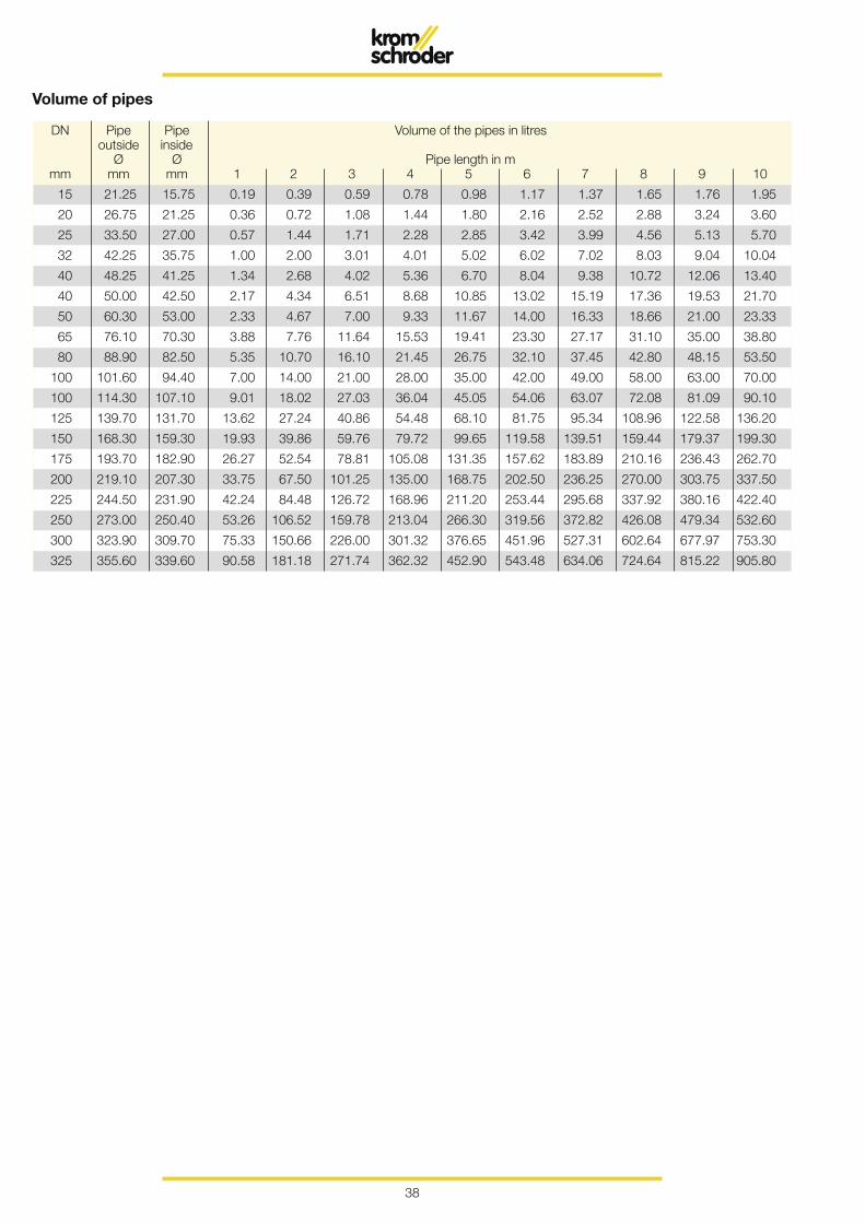
Volume of pipes
DN Pipe Pipe Volume of the pipes in litres outside inside Ø Ø Pipe length in m mm mm mm 1 2 3 4 5 6 7 8 9 10
15 21.25 15.75 0.19 0.39 0.59 0.78 0.98 1.17 1.37 1.65 1.76 1.95
20 26.75 21.25 0.36 0.72 1.08 1.44 1.80 2.16 2.52 2.88 3.24 3.60
25 33.50 27.00 0.57 1.44 1.71 2.28 2.85 3.42 3.99 4.56 5.13 5.70
32 42.25 35.75 1.00 2.00 3.01 4.01 5.02 6.02 7.02 8.03 9.04 10.04
40 48.25 41.25 1.34 2.68 4.02 5.36 6.70 8.04 9.38 10.72 12.06 13.40
40 50.00 42.50 2.17 4.34 6.51 8.68 10.85 13.02 15.19 17.36 19.53 21.70
50 60.30 53.00 2.33 4.67 7.00 9.33 11.67 14.00 16.33 18.66 21.00 23.33
65 76.10 70.30 3.88 7.76 11.64 15.53 19.41 23.30 27.17 31.10 35.00 38.80
80 88.90 82.50 5.35 10.70 16.10 21.45 26.75 32.10 37.45 42.80 48.15 53.50
100 101.60 94.40 7.00 14.00 21.00 28.00 35.00 42.00 49.00 58.00 63.00 70.00
100 114.30 107.10 9.01 18.02 27.03 36.04 45.05 54.06 63.07 72.08 81.09 90.10
125 139.70 131.70 13.62 27.24 40.86 54.48 68.10 81.75 95.34 108.96 122.58 136.20
150 168.30 159.30 19.93 39.86 59.76 79.72 99.65 119.58 139.51 159.44 179.37 199.30
175 193.70 182.90 26.27 52.54 78.81 105.08 131.35 157.62 183.89 210.16 236.43 262.70
200 219.10 207.30 33.75 67.50 101.25 135.00 168.75 202.50 236.25 270.00 303.75 337.50
225 244.50 231.90 42.24 84.48 126.72 168.96 211.20 253.44 295.68 337.92 380.16 422.40
250 273.00 250.40 53.26 106.52 159.78 213.04 266.30 319.56 372.82 426.08 479.34 532.60
300 323.90 309.70 75.33 150.66 226.00 301.32 376.65 451.96 527.31 602.64 677.97 753.30
325 355.60 339.60 90.58 181.18 271.74 362.32 452.90 543.48 634.06 724.64 815.22 905.80
39
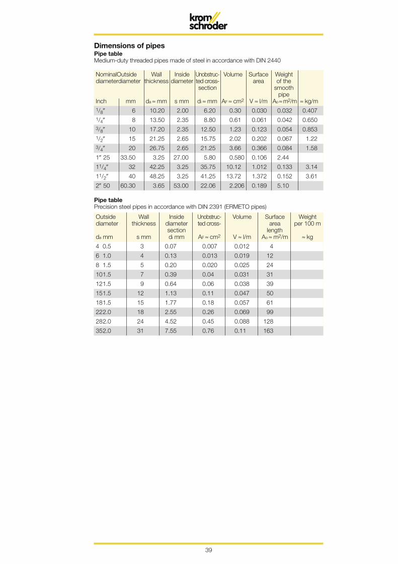
Dimensions of pipesPipe tableMedium-duty threaded pipes made of steel in accordance with DIN 2440
Nominal Outside Wall Inside Unobstruc- Volume Surface Weight diameter diameter thickness diameter ted cross- area of the section smooth pipe Inch mm da ≈ mm s mm di ≈ mm AF ≈ cm2 V ≈ l/m Ao ≈ m2/m ≈ kg/m
1/8 6 10.20 2.00 6.20 0.30 0.030 0.032 0.407
1/4 8 13.50 2.35 8.80 0.61 0.061 0.042 0.650
3/8 10 17.20 2.35 12.50 1.23 0.123 0.054 0.853
1/2 15 21.25 2.65 15.75 2.02 0.202 0.067 1.22
3/4 20 26.75 2.65 21.25 3.66 0.366 0.084 1.58
1 25 33.50 3.25 27.00 5.80 0.580 0.106 2.44
11/4 32 42.25 3.25 35.75 10.12 1.012 0.133 3.14
11/2 40 48.25 3.25 41.25 13.72 1.372 0.152 3.61
2 50 60.30 3.65 53.00 22.06 2.206 0.189 5.10
Outside Wall Inside Unobstruc- Volume Surface Weight diameter thickness diameter ted cross- area per 100 m section length da mm s mm di mm AF ≈ cm2 V ≈ l/m Ao ≈ m2/m ≈ kg
4 0.5 3 0.07 0.007 0.012 4
6 1.0 4 0.13 0.013 0.019 12
8 1.5 5 0.20 0.020 0.025 24
10 1.5 7 0.39 0.04 0.031 31
12 1.5 9 0.64 0.06 0.038 39
15 1.5 12 1.13 0.11 0.047 50
18 1.5 15 1.77 0.18 0.057 61
22 2.0 18 2.55 0.26 0.069 99
28 2.0 24 4.52 0.45 0.088 128
35 2.0 31 7.55 0.76 0.11 163
Pipe tablePrecision steel pipes in accordance with DIN 2391 (ERMETO pipes)
40
α β γ δ ε ζ η ϑ θ ι χ λ µ Alpha Beta Gamma Delta Epsilon Zeta Eta Theta Jota Kappa Lambda My
ν ξ ο π ρ σ ς τ υ ϕ χ ψ ω Ny Xi Omikron Pi Rho Sigma Tau Ypsilon Phi Chi Psi Omega
Α Β Γ Δ Ε Ζ Η Θ Ι Κ Λ Μ Alpha Beta Gamma Delta Epsilon Zeta Eta Theta Jota Kappa Lambda My
Ν Ξ Ο Π Ρ Σ Τ Υ Φ Χ Ψ Ω Ny Xi Omikron Pi Rho Sigma Tau Ypsilon Phi Chi Psi Omega
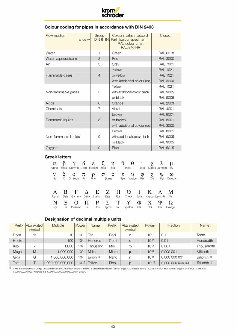
Colour coding for pipes in accordance with DIN 2403
Flow medium Group Colour marks in accord- Closest ance with DIN 6164, Part 1 colour specimen RAL colour chart RAL 840 HR
Water 1 Green RAL 6018
Water vapour/steam 2 Red RAL 3000
Air 3 Grey RAL 7001
Yellow RAL 1021
Flammable gases 4 or yellow RAL 1021
with additional colour red RAL 3000
Yellow RAL 1021
Non-flammable gases 5 with additional colour black RAL 9005
or black RAL 9005
Acids 6 Orange RAL 2003
Chemicals 7 Violet RAL 4001
Brown RAL 8001
Flammable liquids 8 or brown RAL 8001
with additional colour red RAL 3000
Brown RAL 8001
Non-flammable liquids 9 with additional colour black RAL 9005
or black RAL 9005
Oxygen 0 Blue RAL 5015
Greek letters
Prefix Abbreviated Multiple Power Name Prefix Abbreviated Power Fraction Name symbol symbol
Deca da 10 101 Ten Deci d 10-1 0.1 Tenth
Hecto h 100 102 Hundred Centi c 10-2 0.01 Hundredth
Kilo k 1,000 103 Thousand Milli m 10-3 0.001 Thousandth
Mega M 1,000,000 106 Million Micro µ 10-6 0.000 001 Millionth
Giga G 1,000,000,000 109 Billion 1) Nano n 10-9 0.000 000 001 Billionth 1)
Tera T 1,000,000,000,000 1012 Trillion 1) Pico p 10-12 0.000 000 000 001 Trillionth 1)
1) There is a difference in usage between British and American English: a billion is one million million in British English, whereas it is one thousand million in American English; in the US, a trillion is 1,000,000,000,000, whereas it is 1,000,000,000,000,000,000 in Britain.
Designation of decimal multiple units
41
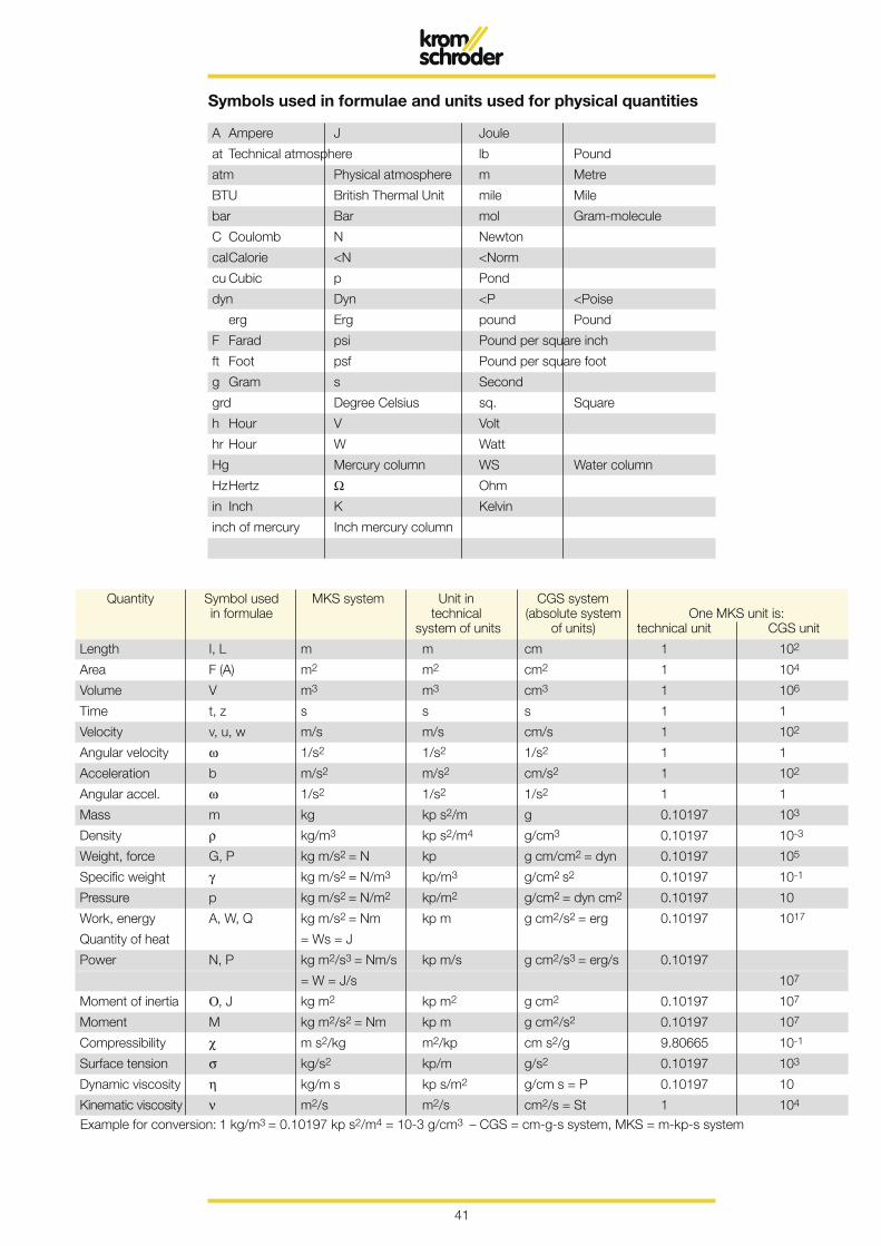
Quantity Symbol used MKS system Unit in CGS system in formulae technical (absolute system One MKS unit is: system of units of units) technical unit CGS unit
Length I, L m m cm 1 102
Area F (A) m2 m2 cm2 1 104
Volume V m3 m3 cm3 1 106
Time t, z s s s 1 1
Velocity v, u, w m/s m/s cm/s 1 102
Angular velocity ω 1/s2 1/s2 1/s2 1 1
Acceleration b m/s2 m/s2 cm/s2 1 102
Angular accel. ω 1/s2 1/s2 1/s2 1 1
Mass m kg kp s2/m g 0.10197 103
Density ρ kg/m3 kp s2/m4 g/cm3 0.10197 10-3
Weight, force G, P kg m/s2 = N kp g cm/cm2 = dyn 0.10197 105
Specific weight γ kg m/s2 = N/m3 kp/m3 g/cm2 s2 0.10197 10-1
Pressure p kg m/s2 = N/m2 kp/m2 g/cm2 = dyn cm2 0.10197 10
Work, energy A, W, Q kg m/s2 = Nm kp m g cm2/s2 = erg 0.10197 1017
Quantity of heat = Ws = J
Power N, P kg m2/s3 = Nm/s kp m/s g cm2/s3 = erg/s 0.10197
= W = J/s 107
Moment of inertia Ο, J kg m2 kp m2 g cm2 0.10197 107
Moment M kg m2/s2 = Nm kp m g cm2/s2 0.10197 107
Compressibility χ m s2/kg m2/kp cm s2/g 9.80665 10-1
Surface tension σ kg/s2 kp/m g/s2 0.10197 103
Dynamic viscosity η kg/m s kp s/m2 g/cm s = P 0.10197 10
Kinematic viscosity ν m2/s m2/s cm2/s = St 1 104
Example for conversion: 1 kg/m3 = 0.10197 kp s2/m4 = 10-3 g/cm3 – CGS = cm-g-s system, MKS = m-kp-s system
A Ampere J Joule
at Technical atmosphere lb Pound
atm Physical atmosphere m Metre
BTU British Thermal Unit mile Mile
bar Bar mol Gram-molecule
C Coulomb N Newton
cal Calorie <N <Norm
cu Cubic p Pond
dyn Dyn <P <Poise
erg Erg pound Pound
F Farad psi Pound per square inch
ft Foot psf Pound per square foot
g Gram s Second
grd Degree Celsius sq. Square
h Hour V Volt
hr Hour W Watt
Hg Mercury column WS Water column
Hz Hertz Ω Ohm
in Inch K Kelvin
inch of mercury Inch mercury column
Symbols used in formulae and units used for physical quantities

42
Conversion of quantities for atmospheric pressure
Height above sea level Pressure
torr mbar = hPa
m
0 760 1013
200 742 989
400 724 966
600 707 943
800 690 921
1000 673 899
1200 657 876
1400 641 854
1600 626 835
1800 611 851
2000 596 795
2200 581 775
2400 567 756
2600 553 737
2800 539 719
3000 525 701
3200 512 684
3400 499 665
3600 487 650
3800 475 632
4000 463 616
5000 405 540
10,000 198 264
20,000 41 55
43
Uni
t sym
bol
Nam
e of
uni
t P
a =
N/m
2 hP
a =
mba
r ba
r kp
/m2
= m
m w
c m
wc
kp/c
m2
= a
t p/
cm2
1 P
a =
1 N
/m2
Pas
cal
1 0.
01
0.00
001
0.10
197
0.00
01
0.00
001
0.01
02
1 m
bar
Milli
bar
100
1 0.
001
10.2
0.
0102
0.
001
1.02
1 ba
r B
ar
100
000
1000
1
1019
7.2
10.1
972
1.01
972
1019
.72
1 kp
/m2
= 1
mm
wc
Millim
etre
wat
er c
olum
n 9.
8066
5 –
– 1
0.00
1 0.
0001
0.
1
1 m
wc
Met
re w
ater
col
umn
9806
.65
98.0
7 0.
0980
7 10
00
1 0.
1 10
0
1 kp
/m2
= 1
at
Tech
nica
l atm
osph
ere
9806
6.5
980.
67
0.09
8067
10
000
10
1
1000
1 at
m
Phy
sica
l atm
osph
ere
1013
25
1013
.25
1.01
325
1033
2.3
10.3
323
1.03
323
1033
.23
1 to
rr =
1 m
m H
g M
illim
etre
m
ercu
ry c
olum
n 13
3.32
2 1.
33
0.00
133
13.5
951
0.01
3595
0.
0013
6 1.
3595
1
1 lb
/in2
(psi
) P
ound
-for
ce
per s
quar
e in
ch
6894
.76
69.9
5 0.
0689
5 70
3.07
0.
7030
7 0.
0703
1 70
.307
1 lb
/ft2
(psf
) P
ound
-for
ce
per s
quar
e fo
ot
47.8
803
0.48
0.
0004
8 4.
8823
4 0.
0048
8 0.
0004
8 0.
4882
4
1 in
Hg
Inch
mer
cury
col
umn
3386
.39
33.8
6 0.
0336
8 34
5.31
6 0.
3453
2 0.
0345
3 34
.531
6
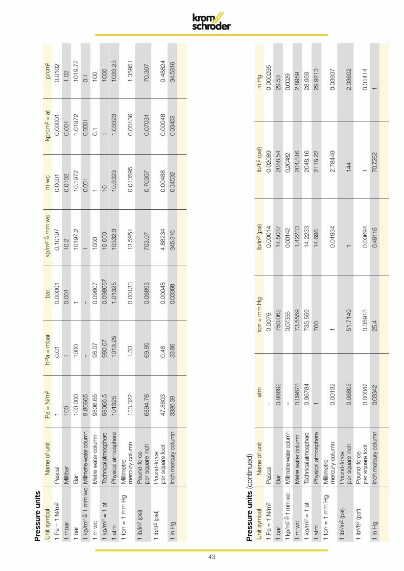
Pre
ssur
e un
its
Uni
t sym
bol
Nam
e of
uni
t at
m
torr
= m
m H
g lb
/in2
(psi
) lb
/ft2
(psf
) in
Hg
1 P
a =
1 N
/m2
Pas
cal
– 0.
0075
0.
0001
4 0.
0208
9 0.
0002
95
1 ba
r B
ar
0.98
692
750.
062
14.5
037
2088
.54
29.5
3
1 kp
/m2
= 1
mm
wc
Millim
etre
wat
er c
olum
n –
0.07
356
0.00
142
0,20
482
0.00
29
1 m
wc
Met
re w
ater
col
umn
0.09
678
73.5
559
1.42
233
204.
816
2.89
59
1 kp
/m2
= 1
at
Tech
nica
l atm
osph
ere
0.96
784
735.
559
14.2
233
2048
.16
28.9
59
1 at
m
Phy
sica
l atm
osph
ere
1 76
0 14
.696
21
16.2
2 29
.921
3
1 to
rr =
1 m
m H
g M
illim
etre
m
ercu
ry c
olum
n 0.
0013
2 1
0.01
934
2.78
449
0.03
937
1 lb
f/in2
(psi
) P
ound
-for
ce
per s
quar
e in
ch
0.06
805
51.7
149
1 14
4 2.
0360
2
1 lb
f/ft2
(psf
) P
ound
-for
ce
per s
quar
e fo
ot
0.00
047
0.35
913
0.00
694
1 0.
0141
4
1 in
Hg
Inch
mer
cury
col
umn
0.03
342
25.4
0.
4911
5 70
.726
2 1
Pre
ssur
e un
its
(con
tinue
d)
44
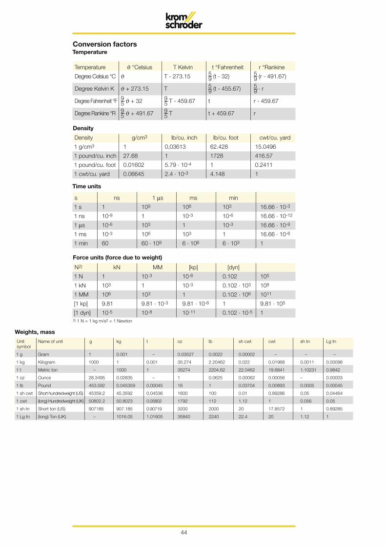
2) 1 N = 1 kg m/s2 = 1 Newton
Temperature ϑ °Celsius T Kelvin t °Fahrenheit r °Rankine
Degree Celsius °C ϑ T - 273.15 5 9 (t - 32) 5 9 (r - 491.67)
Degree Kelvin K ϑ + 273.15 T 5 9 (t - 455.67) 5 9 . r
Degree Fahrenheit °F 9 5 ϑ + 32 9 5 T - 459.67 t r - 459.67
Degree Rankine °R 9 5 ϑ + 491.67 9 5 T t + 459.67 r
Conversion factorsTemperature
Density g/cm3 lb/cu. inch lb/cu. foot cwt/cu. yard
1 g/cm3 1 0,03613 62.428 15.0496
1 pound/cu. inch 27.68 1 1728 416.57
1 pound/cu. foot 0.01602 5.79 . 10-4 1 0.2411
1 cwt/cu. yard 0.06645 2.4 . 10-3 4.148 1
Density
Time units
Force units (force due to weight)
Unit Name of unit g kg t oz lb sh cwt cwt sh tn Lg tn symbol
1 g Gram 1 0.001 – 0.03527 0.0022 0.00002 – – –
1 kg Kilogram 1000 1 0.001 35.274 2.20462 0.022 0.01968 0.0011 0.00098
1 t Metric ton – 1000 1 35274 2204.62 22.0462 19.6841 1.10231 0.9842
1 oz Ounce 28.3495 0.02835 – 1 0.0625 0.00062 0.00056 – 0.00003
1 lb Pound 453.592 0.045359 0.00045 16 1 0.03704 0.00893 0.0005 0.00045
1 sh cwt Short hundredweight (US) 45359.2 45.3592 0.04536 1600 100 0.01 0.89286 0.05 0.04464
1 cwt (long) Hundredweight (UK) 50802.2 50.8023 0.05802 1792 112 1.12 1 0.056 0.05
1 sh tn Short ton (US) 907185 907.185 0.90719 3200 2000 20 17.8572 1 0.89285
1 Lg tn (long) Ton (UK) – 1016.05 1.01605 35840 2240 22.4 20 1.12 1
Weights, mass
s ns 1 µs ms min
1 s 1 109 106 103 16.66 . 10-3
1 ns 10-9 1 10-3 10-6 16.66 . 10-12
1 µs 10-6 103 1 10-3 16.66 . 10-9
1 ms 10-3 106 103 1 16.66 . 10-6
1 min 60 60 . 109 6 . 106 6 . 103 1
N2) kN MM [kp] [dyn]
1 N 1 10-3 10-6 0.102 105
1 kN 103 1 10-3 0.102 . 103 108
1 MM 106 103 1 0.102 . 106 1011
[1 kp] 9.81 9.81 . 10-3 9.81 . 10-6 1 9.81 . 105
[1 dyn] 10-5 10-8 10-11 0.102 . 10-5 1
45
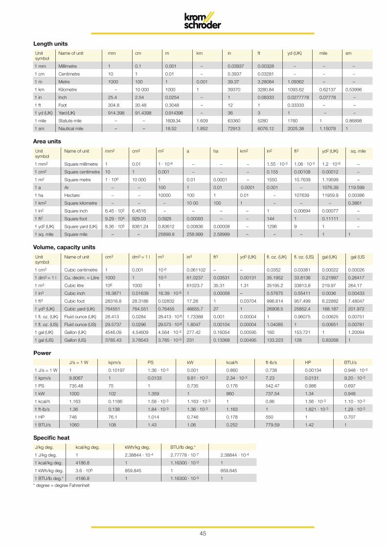
Unit Name of unit mm cm m km in ft yd (UK) mile sm symbol
1 mm Millimetre 1 0.1 0.001 – 0.03937 0.00328 – – –
1 cm Centimetre 10 1 0.01 – 0.3937 0.03281 – – –
1 m Metre 1000 100 1 0.001 39.37 3.28084 1.09362 – –
1 km Kilometre – 10 000 1000 1 39370 3280.84 1093.62 0.62137 0.53996
1 in Inch 25.4 2.54 0.0254 – 1 0.08333 0.0277778 0.07778 –
1 ft Foot 304.8 30.48 0.3048 – 12 1 0.33333 – –
1 yd (UK) Yard (UK) 914.398 91.4398 0.914398 – 36 3 1 – –
1 mile Statute mile – – 1609.34 1.609 63360 5280 1760 1 0.86898
1 sm Nautical mile – – 18.52 1.852 72913 6076.12 2025.38 1.15078 1
Length units
Unit Name of unit mm2 cm2 m2 a ha km2 in2 ft2 yd2 (UK) sq. mile symbol
1 mm2 Square millimetre 1 0.01 1 . 10-6 – – – 1.55 . 10-3 1.08 . 10-5 1.2 . 10-6 –
1 cm2 Square centimetre 10 1 0.001 – – – 0.155 0.00108 0.00012 –
1 m2 Square metre 1 . 106 10 000 1 0.01 0.0001 – 1550 10.7639 1.19599 –
1 a Ar – – 100 1 0.01 0.0001 0.001 – 1076.39 119.599
1 ha Hectare – – 10000 100 1 0.01 – 107639 11959.9 0.00386
1 km2 Square kilometre – – – 10 00 100 1 – – – 0.3861
1 in2 Square inch 6.45 . 102 6.4516 – – – – 1 0.00694 0.00077 –
1 ft2 Square foot 9.29 . 104 929.03 0.0929 0.00093 – – 144 1 0.11111 –
1 yd2 (UK) Square yard (UK) 8.36 . 105 8361.24 0.83612 0.00836 0.00008 – 1296 9 1 –
1 sq. mile Square mile – – 25899.9 258.999 2.58999 – – – 1 1
Area units
Unit Name of unit cm3 dm3 = 1 l m3 in3 ft3 yd3 (UK) fl. oz. (UK) fl. oz. (US) gal (UK) gal (US symbol
1 cm3 Cubic centimetre 1 0.001 10-6 0.061102 – – 0.0352 0.03381 0.00022 0.00026
1 dm3 = 1 l Cu. decim. = Litre 1000 1 10-3 61.0237 0.03531 0.00131 35.1952 33.8138 0.21997 0.26417
1 m3 Cubic litre 106 1000 1 61023.7 35.31 1.31 35195.2 33813.8 219.97 264.17
1 in3 Cubic inch 16.3871 0.01639 16.39 . 10-6 1 0.00058 – 0.57675 0.55411 0.0036 0.00433
1 ft3 Cubic foot 28316.8 28.3186 0.02832 17.28 1 0.03704 996.614 957.499 6.22882 7.48047
1 yd3 (UK) Cubic yard (UK) 764551 764.551 0.76455 46655.7 27 1 26908.5 25852.4 168.187 201.972
1 fl. oz. (UK) Fluid ounce (UK) 28.413 0.0284 28.413 . 10-6 1.73388 0.001 0.00004 1 0.96075 0.00625 0.00751
1 fl. oz. (US) Fluid ounce (US) 29.5737 0.0296 29.573 . 10-6 1.8047 0.00104 0.00004 1.04085 1 0.00651 0.00781
1 gal (UK) Gallon (UK) 4546.09 4.54609 4.564 . 10-3 277.42 0.16054 0.00595 160 153.721 1 1.20094
1 gal (US) Gallon (US) 3785.43 3.78543 3.785 . 10-3 231 0.13368 0.00495 133.223 128 0.83268 1
Volume, capacity units
J/s = 1 W kpm/s PS kW kcal/h ft-lb/s HP BTU/s
1 J/s = 1 W 1 0.10197 1.36 . 10-3 0.001 0.860 0.738 0.00134 0.948 . 10-3
1 kpm/s 9.8067 1 0.0133 9.81 . 10-3 2.34 . 10-3 7.23 0.0131 9.20 . 10-3
1 PS 735.48 75 1 0.735 0.176 542.47 0.986 0.697
1 kW 1000 102 1.359 1 860 737.54 1.34 0.948
1 kcal/h 1.163 0.1186 1.58 . 10-3 1.163 . 10-3 1 0.86 1.56 . 10-3 1.10 . 10-3
1 ft-lb/s 1.36 0.138 1.84 . 10-3 1.36 . 10-3 1.163 1 1.821 . 10-3 1.29 . 10-3
1 HP 746 76.1 1.014 0.746 0.178 550 1 0.707
1 BTU/s 1060 108 1.43 1.06 0.252 779.59 1.42 1
Power
Specific heat
* degree = degree Fahrenheit
J/kg deg. kcal/kg deg. kWh/kg deg. BTU/lb deg.*
1 J/kg deg. 1 2.38844 . 10-4 2.77778 . 10-7 2.38844 . 10-4
1 kcal/kg deg. 4186.8 1 1.16300 . 10-3 1
1 kWh/kg deg. 3.6 . 106 859.845 1 859.845
1 BTU/lb deg.* 4186.8 1 1.16300 . 10-3 1
46
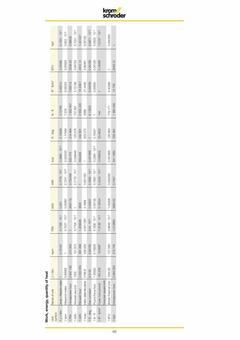
Wo
rk, e
nerg
y, q
uant
ity
of
heat
Uni
t N
ame
of u
nit
J =
Nm
kp
m
PS
h kW
s kW
h kc
al
R .
deg.
lb
. ft
ft3 .
lb/in
2 B
TU
hph
sym
bol
1 J
= N
m
Joul
e =
New
ton-
met
re
1 0.
1019
7 3.
7768
. 10
-7
0.00
1 2.
7778
. 10
-7
2.38
85 .
10-4
0.
1202
8 0.
7376
5 0.
0051
2 0.
0009
5 3.
7251
. 10
-7
1 kp
m
Kilo
pond
-met
re
9.80
665
1 3.
7037
. 10
-6
0.00
981
2.72
41 .
10-6
0.
0023
42
1.17
949
7.23
3 0.
0502
3 0.
0092
9 3.
653
. 10-
6
1 P
Sh
Hor
sepo
wer
-hou
r 2
647
790
270
000
1 26
47.7
9 0.
7354
99
632.
415
318
464
1 95
2 90
7 13
561.
9 25
08.3
3 0.
9863
2
1 kW
s K
ilow
att-
seco
nd
1000
10
1.97
2 3.
7768
. 10
-4
1 2.
7778
. 10
-4
0.23
8846
12
0.27
6 73
7.56
1 5.
1219
6 0.
9473
3 3.
7251
. 10
-4
1 kW
h K
ilow
att-
hour
3
000
000
367
098
1.35
9648
36
00
1 85
9.84
5 43
2 99
1 2
655
220
18 4
39.1
34
12.1
4 1.
3410
21
1 kc
alIT
In
tern
. tab
le k
iloca
lorie
41
86.8
42
6.93
5 0.
0011
581
4.18
68
0.00
1163
1
503.
575
3088
21
.444
6 3.
9638
1 0.
0015
6
1 R
. de
g.
Gas
con
stan
t 8.
3142
0.
8478
2 3.
14 .
10-6
0.
0083
1 2.
3095
. 10
-4
0.00
1986
1
6.13
223
0.04
259
0.00
788
3.09
71 .
10-6
1 lb
. ft
Pou
nd-f
orce
-foo
t 1.
3558
2 0.
1382
6 5.
1206
. 10
-7
0.00
136
3.76
62 .
10-7
3.
2383
. 10
-4
0.16
307
1 0.
0069
5 0.
0012
8 5.
0505
. 10
-7
1 ft3
. lb
/in2
Cub
ic fo
ot p
ound
- 19
5.23
8 19
.908
7 7.
3736
. 10
-5
0.19
524
5.42
33 .
10-5
0.
0466
32
23.4
822
144
1 0.
1849
5 7.
2727
. 10
-5
fo
rce
per s
quar
e in
ch
1 B
TU
Brit
ish
Ther
mal
Uni
t 10
55.0
6 10
7.58
5 3.
9848
. 10
-4
1.05
506
0.00
0293
0.
2519
95
126.
963
778.
171
5.40
398
1 0.
0003
93
1 hp
h H
orse
pow
er-h
our
2 68
4 52
0 27
3 74
5 1.
0138
69
2684
.52
0.74
57
641.
1863
33
2 88
1 1
980
000
13 7
50
2543
.12
1
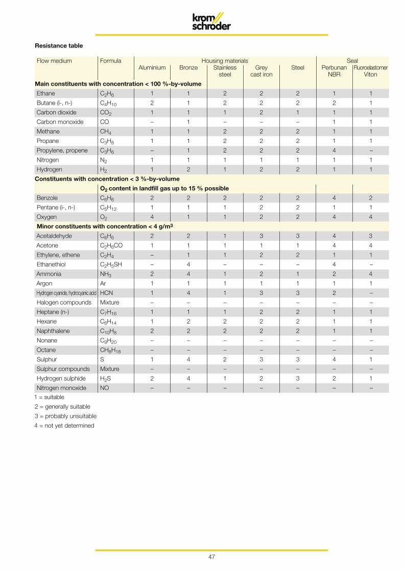
47
1 = suitable
2 = generally suitable
3 = probably unsuitable
4 = not yet determined
Flow medium Formula Housing materials Seal Aluminium Bronze Stainless Grey Steel Perbunan Fluoroelastomer steel cast iron NBR Viton
Main constituents with concentration < 100 %-by-volume
Ethane C2H6 1 1 2 2 2 1 1
Butane (i-, n-) C4H10 2 1 2 2 2 2 1
Carbon dioxide CO2 1 1 1 2 1 1 1
Carbon monoxide CO – 1 – – – 1 1
Methane CH4 1 1 2 2 2 1 1
Propane C3H8 1 1 2 2 2 1 1
Propylene, propene C3H6 – 1 2 2 2 4 –
Nitrogen N2 1 1 1 1 1 1 1
Hydrogen H2 1 2 1 2 2 1 1
Constituents with concentration < 3 %-by-volume
O2 content in landfill gas up to 15 % possible
Benzole C6H6 2 2 2 2 2 4 2
Pentane (i-, n-) C5H12 1 1 1 2 2 1 1
Oxygen O2 4 1 1 2 2 4 4
Minor constituents with concentration < 4 g/m3
Acetaldehyde C6H6 2 2 1 3 3 4 3
Acetone C2H6CO 1 1 1 1 1 4 4
Ethylene, ethene C2H4 – 1 1 2 2 1 1
Ethanethiol C2H5SH – 4 – – – 4 –
Ammonia NH3 2 4 1 2 1 2 4
Argon Ar 1 1 1 1 1 1 1
Hydrogen cyanide, hydrocyanic acid HCN 1 4 1 3 3 2 –
Halogen compounds Mixture – – – – – – –
Heptane (n-) C7H16 1 1 1 2 2 1 1
Hexane C6H14 1 2 2 2 2 1 1
Naphthalene C10H8 2 2 2 2 2 1 1
Nonane C9H20 – – – – – – –
Octane CH8H18 – – – – – – –
Sulphur S 1 4 2 3 3 4 1
Sulphur compounds Mixture – – – – – – –
Hydrogen sulphide H2S 2 4 1 2 3 2 1
Nitrogen monoxide NO – – – – – – –
Resistance table


Contactwww.kromschroeder.com Sales
Elster GmbH Postfach 2809 · 49018 Osnabrück Strotheweg 1 · 49504 Lotte (Büren) GermanyT +49 541 1214-0 F +49 541 1214-370 [email protected]
We reserve the right to make technical modifications in the interests of progress.Copyright © 2013 Elster GmbH All rights reserved.


