General DAQSTATION Specifications DX2000 · STANDARD SPECIFICATIONS General Specifications...
20
General Specifications <<Contents>> <<Index>> GS 04L42B01-01E GS 04L42B01-01E ©Copyright November. 2005 1st Edition Nov. 2005(KP) 5th Edition May 2007(KP) DAQSTATION DX2000 OVERVIEW The DX2000 is a DAQSTATION that displays real-time measured data on a color LCD and saves data on a CompactFlash memory card (CF card). It can be hooked up to network via Ethernet, which enables to inform by E- mail and to monitor on Web site as well as to transfer files by using FTP. Also, it can communicate with Modbus/RTU or Modbus/TCP. It comes with a four, eight, ten, twenty, thirty, forty- channel or forty eight-channel model. As the input signal, a DC voltage, thermocouple, resistance temperature detector, or contact signal can be set to each channel. The data saved on a CF card can be converted by data conversion software to Lotus 1-2-3, Excel, or ASCII format file, facilitating processing on a PC. Not only this, the Viewer software allows a PC to display waveforms on its screen and to print out waveforms. STANDARD SPECIFICATIONS General Specifications Construction Mounting: Flush panel mounting (on a vertical plane) Mounting may be inclined downward up to 30 degrees from a horizontal plane. Allowable panel thickness: 2 to 26 mm Material: Case: drawn steel Bezel: polycarbonate Display filter: polycarbonate Case color: Case: Grayish blue green (Munsell 2.0B 5.0/1.7 or equivalent) Bezel: Charcoal grey light (Munsell 10B 3.6/0.3 or equivalent) Front panel: Water and dust-proof* (based on IEC529-IP65 and NEMA No.250 TYPE4 for indoor locations (except external icing test)) *Except for side-by-side mounting. Dimensions: 288 (W) 288 (H) 221.6 (D) mm 288 (W) 288 (H) 226 (D) *mm *In case of /H2 or /PM1 option is specified. Weight: DX2004, DX2010: approx. 6.0 kg* DX2008, DX2020: approx. 6.3 kg* DX2030 : approx. 6.9 kg* DX2040, DX2048: approx. 7.3 kg* *without optional features Input Number of inputs: DX2004: four channels DX2008: eight channels DX2010: ten channels DX2020: twenty channels DX2030: thirty channels DX2040: forty channels DX2048: forty eight channels Measurement interval: DX2004, DX2008: 125 ms, 250 ms, 25 ms (fast sampling mode*) DX2010, DX2020, DX2030, DX2040, DX2048: 1 s (Not available when A/D integration time is set to 100 ms), 2 s, 5 s, 125 ms (fast sampling mode*) * A/D integration time is fixed to 1.67 ms in case of fast sampling mode. Inputs: DCV (DC voltage), TC (thermocouple), RTD (resistance temperature detector), DI (digital input for event recording), DCA (DC current with external shunt resistor attached)
-
Upload
doannguyet -
Category
Documents
-
view
277 -
download
2
Transcript of General DAQSTATION Specifications DX2000 · STANDARD SPECIFICATIONS General Specifications...
GeneralSpecifications
<<Contents>> <<Index>>
GS 04L42B01-01E
GS 04L42B01-01E©Copyright November. 2005
1st Edition Nov. 2005(KP)5th Edition May 2007(KP)
DAQSTATIONDX2000
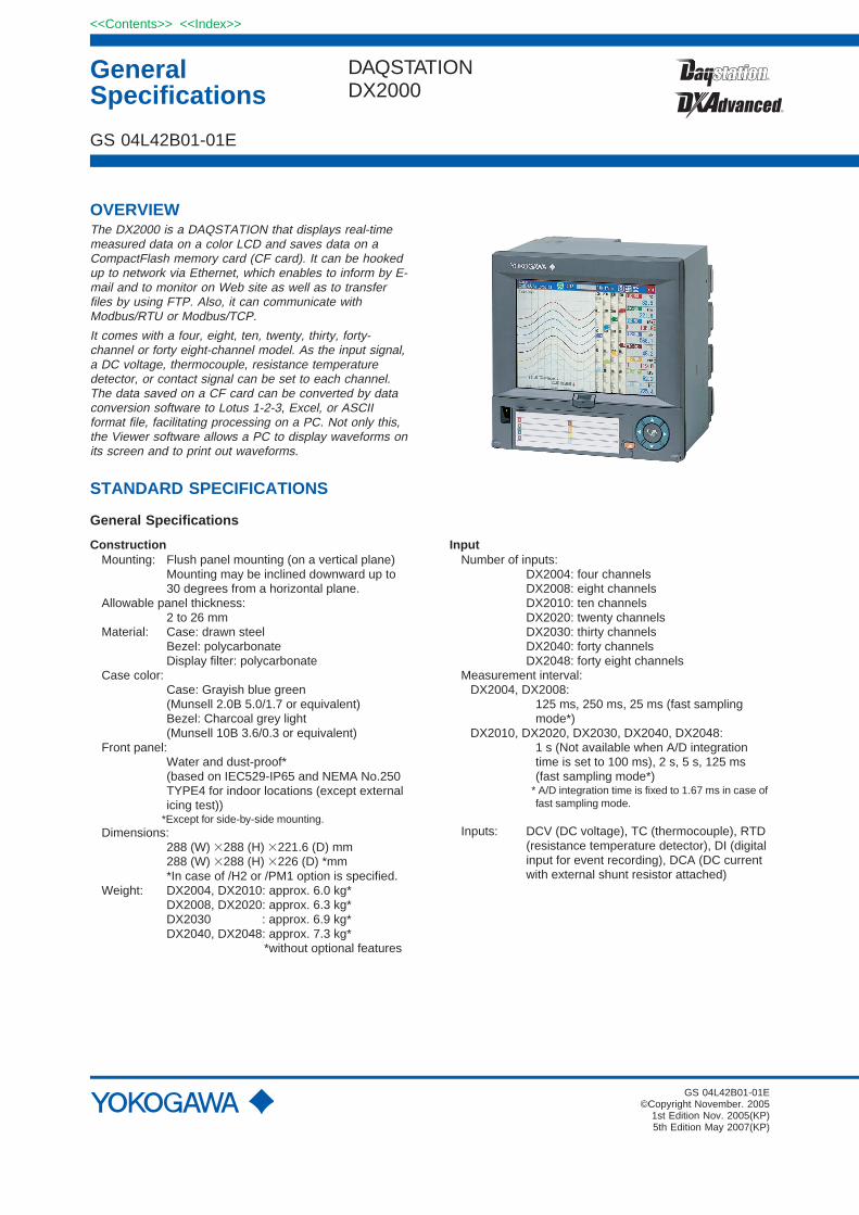
OVERVIEWThe DX2000 is a DAQSTATION that displays real-timemeasured data on a color LCD and saves data on aCompactFlash memory card (CF card). It can be hookedup to network via Ethernet, which enables to inform by E-mail and to monitor on Web site as well as to transferfiles by using FTP. Also, it can communicate withModbus/RTU or Modbus/TCP.
It comes with a four, eight, ten, twenty, thirty, forty-channel or forty eight-channel model. As the input signal,a DC voltage, thermocouple, resistance temperaturedetector, or contact signal can be set to each channel.The data saved on a CF card can be converted by dataconversion software to Lotus 1-2-3, Excel, or ASCIIformat file, facilitating processing on a PC. Not only this,the Viewer software allows a PC to display waveforms onits screen and to print out waveforms.
STANDARD SPECIFICATIONS
General Specifications
ConstructionMounting: Flush panel mounting (on a vertical plane)
Mounting may be inclined downward up to30 degrees from a horizontal plane.
Allowable panel thickness:2 to 26 mm
Material: Case: drawn steelBezel: polycarbonateDisplay filter: polycarbonate
Case color:Case: Grayish blue green(Munsell 2.0B 5.0/1.7 or equivalent)Bezel: Charcoal grey light(Munsell 10B 3.6/0.3 or equivalent)
Front panel:Water and dust-proof*(based on IEC529-IP65 and NEMA No.250TYPE4 for indoor locations (except externalicing test))
*Except for side-by-side mounting.Dimensions:
288 (W) 288 (H) 221.6 (D) mm288 (W) 288 (H) 226 (D) *mm*In case of /H2 or /PM1 option is specified.
Weight: DX2004, DX2010: approx. 6.0 kg*DX2008, DX2020: approx. 6.3 kg*DX2030 : approx. 6.9 kg*DX2040, DX2048: approx. 7.3 kg*
*without optional features
InputNumber of inputs:
DX2004: four channelsDX2008: eight channelsDX2010: ten channelsDX2020: twenty channelsDX2030: thirty channelsDX2040: forty channelsDX2048: forty eight channels
Measurement interval:DX2004, DX2008:
125 ms, 250 ms, 25 ms (fast samplingmode*)
DX2010, DX2020, DX2030, DX2040, DX2048:1 s (Not available when A/D integrationtime is set to 100 ms), 2 s, 5 s, 125 ms(fast sampling mode*)
* A/D integration time is fixed to 1.67 ms in case offast sampling mode.
Inputs: DCV (DC voltage), TC (thermocouple), RTD(resistance temperature detector), DI (digitalinput for event recording), DCA (DC currentwith external shunt resistor attached)
2
All Rights Reserved. Copyright © 2005, Yokogawa Electric Corporation
<<Contents>> <<Index>>
GS 04L42B01-01E 5th Edition May 21,2007-00
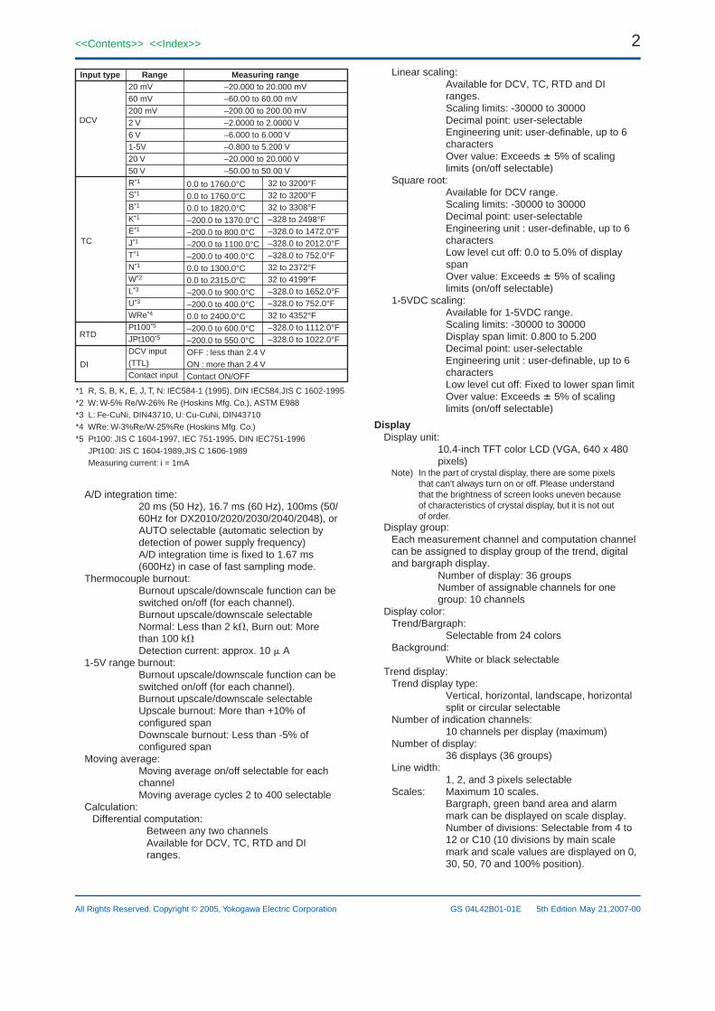
Input type Range
0.0 to 1760.0°C0.0 to 1760.0°C0.0 to 1820.0°C–200.0 to 1370.0°C–200.0 to 800.0°C–200.0 to 1100.0°C–200.0 to 400.0°C0.0 to 1300.0°C0.0 to 2315.0°C–200.0 to 900.0°C–200.0 to 400.0°C0.0 to 2400.0°C–200.0 to 600.0°C–200.0 to 550.0°COFF : less than 2.4 VON : more than 2.4 VContact ON/OFF
DCV
TC
RTD
DI
*1 R, S, B, K, E, J, T, N: IEC584-1 (1995), DIN IEC584,JIS C 1602-1995*2 W: W-5% Re/W-26% Re (Hoskins Mfg. Co.), ASTM E988*3 L: Fe-CuNi, DIN43710, U: Cu-CuNi, DIN43710*4 WRe: W-3%Re/W-25%Re (Hoskins Mfg. Co.)*5 Pt100: JIS C 1604-1997, IEC 751-1995, DIN IEC751-1996 JPt100: JIS C 1604-1989,JIS C 1606-1989 Measuring current: i = 1mA
32 to 3200°F32 to 3200°F32 to 3308°F–328 to 2498°F–328.0 to 1472.0°F–328.0 to 2012.0°F–328.0 to 752.0°F32 to 2372°F32 to 4199°F–328.0 to 1652.0°F–328.0 to 752.0°F32 to 4352°F–328.0 to 1112.0°F–328.0 to 1022.0°F
Measuring range–20.000 to 20.000 mV–60.00 to 60.00 mV–200.00 to 200.00 mV–2.0000 to 2.0000 V–6.000 to 6.000 V–0.800 to 5.200 V–20.000 to 20.000 V–50.00 to 50.00 V
20 mV60 mV200 mV2 V6 V1-5V20 V50 VR*1
S*1
B*1
K*1
E*1
J*1
T*1
N*1
W*2
L*3
U*3
WRe*4
Pt100*5
JPt100*5
DCV input(TTL)Contact input
A/D integration time:20 ms (50 Hz), 16.7 ms (60 Hz), 100ms (50/60Hz for DX2010/2020/2030/2040/2048), orAUTO selectable (automatic selection bydetection of power supply frequency)A/D integration time is fixed to 1.67 ms(600Hz) in case of fast sampling mode.
Thermocouple burnout:Burnout upscale/downscale function can beswitched on/off (for each channel).Burnout upscale/downscale selectableNormal: Less than 2 k, Burn out: Morethan 100 kDetection current: approx. 10 A
1-5V range burnout:Burnout upscale/downscale function can beswitched on/off (for each channel).Burnout upscale/downscale selectableUpscale burnout: More than +10% ofconfigured spanDownscale burnout: Less than -5% ofconfigured span
Moving average:Moving average on/off selectable for eachchannelMoving average cycles 2 to 400 selectable
Calculation:Differential computation:
Between any two channelsAvailable for DCV, TC, RTD and DIranges.
Linear scaling:Available for DCV, TC, RTD and DIranges.Scaling limits: -30000 to 30000Decimal point: user-selectableEngineering unit: user-definable, up to 6charactersOver value: Exceeds 5% of scalinglimits (on/off selectable)
Square root:Available for DCV range.Scaling limits: -30000 to 30000Decimal point: user-selectableEngineering unit : user-definable, up to 6charactersLow level cut off: 0.0 to 5.0% of displayspanOver value: Exceeds 5% of scalinglimits (on/off selectable)
1-5VDC scaling:Available for 1-5VDC range.Scaling limits: -30000 to 30000Display span limit: 0.800 to 5.200Decimal point: user-selectableEngineering unit : user-definable, up to 6charactersLow level cut off: Fixed to lower span limitOver value: Exceeds 5% of scalinglimits (on/off selectable)
DisplayDisplay unit:
10.4-inch TFT color LCD (VGA, 640 x 480pixels)
Note) In the part of crystal display, there are some pixelsthat can't always turn on or off. Please understandthat the brightness of screen looks uneven becauseof characteristics of crystal display, but it is not outof order.
Display group:Each measurement channel and computation channelcan be assigned to display group of the trend, digitaland bargraph display.
Number of display: 36 groupsNumber of assignable channels for onegroup: 10 channels
Display color:Trend/Bargraph:
Selectable from 24 colorsBackground:
White or black selectableTrend display:
Trend display type:Vertical, horizontal, landscape, horizontalsplit or circular selectable
Number of indication channels:10 channels per display (maximum)
Number of display:36 displays (36 groups)
Line width:1, 2, and 3 pixels selectable
Scales: Maximum 10 scales.Bargraph, green band area and alarmmark can be displayed on scale display.Number of divisions: Selectable from 4 to12 or C10 (10 divisions by main scalemark and scale values are displayed on 0,30, 50, 70 and 100% position).
3<<Contents>> <<Index>>
All Rights Reserved. Copyright © 2005, Yokogawa Electric Corporation GS 04L42B01-01E 5th Edition May 21,2007-00
Waveform span rate:15, 30 sec.,1, 2, 5, 10, 15, 20, 30 min., 1,2, 4, 10 hours/div selectable(15 sec/div is available for only DX2004and DX2008)
Circular waveform span rate:20, 30 min., 1, 2, 6, 8, 12, 16 hours, 1, 2days, 1, 2, 4 weeks/rev selectable(20 min/rev is available for only DX2004and DX2008)
Bargraph display:Direction: Vertical or horizontal selectableNumber of indication channels:
10 channels per displayNumber of display:
36 displays (36 groups)Scales: Green band area and alarm mark can be
displayed on scale display.Number of divisions: Selectable from 4 to12Reference position: Left, right or center
Display renewal rate: 1 sDigital indication:
Number of indication channels:10 channels per display
Number of display:36 displays (36 groups)
Display renewal rate: 1 sOverview display:
Number of indication channels:Measuring values and alarm status of allchannels
Information display:Alarm summary display:
Display the list of latest 1000 alarmssummary.Jump to historical trend display by cursorpointing.
Message summary display:Display the list of latest 450 messagesand time.Jump to historical trend display by cursorpointing.
Memory information:Display the file list in internal memory.Jump to historical trend display by cursorpointing.
Report information:Display the report data in internal memory.
Modbus status:Display the Modbus status.
Relay status:Display the on/off status of internal switchand relay output.
Log display:Log display types:
Login log, error log, communication log,FTP log, Web log, E-mail log, SNTP log,DHCP log, Modbus log
Tags:Number of characters:
16 characters maximumMessages:
Number of characters:32 characters maximum
Number of messages:100 messages (including 10 free mes-sages)
Message adding function:Message can be added on historicaldisplay.
Other display contents:Status display area:
Date & time (year/month/day,hour:minute:second), batch name (batchnumber + lot number), login user name,display name, internal memory status,status indication icon
Trend display area:Grid lines (number of divisions selectablefrom 4 to 12), hour : minutes on grid, triplevels (line widths are selectable from 1, 2and 3 pixels)
Data referencing function:Display the retrieved data (display data or event data)
from internal or external memory.Display format:
Whole display or divided to 2 areasTime axis operation:
Display magnification or reduction, scrollby key operation
Display auto scroll function:Display group of monitor display (trenddisplay, bargraph display and digital display)automatically changes in a preset interval(5, 10, 20, 30 s and 1 min).
LCD saver function:The LCD backlight automatically dims or off(selectable) if no key is touched for a certainpreset time (can be set from 1, 2, 5, 10, 30,and 60 min).
Display register function:Up to 8 display types can be registered withdisplay name.
Display auto return function:The display type automatically returns toregisterd display type if no key is touchedfor a certain preset time (can be set from 1,2, 5, 10, 20, 30 and 60 min)
Temperature unit:°C or °F selectable
Data Saving FunctionExternal storage medium:
Medium: CompactFlash memory card (CF card)Format: FAT16 or FAT32
Internal memory:Medium: Flash memoryCapacity: Selectable from 80MB or 200MBMaximum number of files can be saved:
400 files (total number of display data fileand event data file)
Manual saving:Data files in internal memory can be saved manually.Selectable form all data saving or selected datasaving.Drive: CF card or USB flash drive (only for USB option)
Automatic saving:Display data:
Periodic saving to CF cardEvent data:
In case of trigger free...Periodic saving toCF cardIn case of using trigger...Save the datawhen sampling is finished
Media FIFO function :Allows the oldest file to be deleted and the
4
All Rights Reserved. Copyright © 2005, Yokogawa Electric Corporation
<<Contents>> <<Index>>
GS 04L42B01-01E 5th Edition May 21,2007-00
newest file to be saved if the free space onthe CF card is insufficient (on/off selectable).
Data Saving Period:Display data file:
Linked with the waveform span rateEvent file: Linked with the specified sampling period
Event File Sampling Period:DX2004, DX2008:
Selectable from 25, 125, 250, 500 ms, and1, 2, 5, 10, 30, 60, 120, 300, and 600 s*
DX2010, DX2020, DX2030, DX2040, DX2048:Selectable from 125, 250, 500 ms, and 1,2, 5, 10, 30, 60, 120, 300, and 600 s*
*Sampling period faster than measurement intervalcan not be selected.
Measurement data File:The following two file types can be created.
Event file (stores instantaneous valuessampled periodically at a specifiedsampling rate)Display data file (stores the maximum andminimum values for each waveform spanrate from among measured data sampledat measurement intervals)
Files can be created in the following combinations.(a) Event file + display data file(b) Display data file only(c) Event file only
Data format: YOKOGAWA private format (Binary)Maximum data size per file:
8,000,000 byte (8MB)Data per channel:
Display data file:Measurement data......4 byte/dataMathematical data......8 byte/dataExternal channel data..4 byte/data
Event data file:Measurement data......2 byte/dataMathematical data......4 byte/dataExternal channel data..2 byte/data
Sampling time:The sampling time per file (8MB) during manual datasaving can be determined by the formula "number ofdata items per channel x interval of data saving."This logic is explained in more detail below:1) When handling display data files only
If we assume that the number of measuringchannels is 30, the number of computing channelsis 10, and the display update interval is 30 min/div(60 sec waveform span rate), then:
Number of data items per channel = 8,000,000bytes/(8 bytes(time stamp) + 30 x 4 bytes + 10 x8 bytes) = 38,462 data itemsSampling time per file = 38,462 x 60 sec =2,307,720 sec = approx. 26 days
2) When handling event files onlyIf we assume that the number of measuringchannels is 30, the number of computing channelsis 10, and the data saving interval is 1 sec, then :
Number of data items per channel = 8,000,000bytes/(8 bytes(time stamp) + 30 x 2 bytes + 10 x4 bytes) = 74,074 data itemsSampling time per file = 74,074 x 1 sec =74,074 sec = approx. 20 hours
3)When handling both display data files and eventfiles
The sampling time is calculated by defining the sizeof data items in a display data file as 8,000,000bytes and the size of data items in an event data fileas 8,000,000 bytes. The method of calculation isthe same as shown above.
Examples of Sampling Time for 1 file (8MB)*:*If sampling time exceeds 31 days, data file is divided.
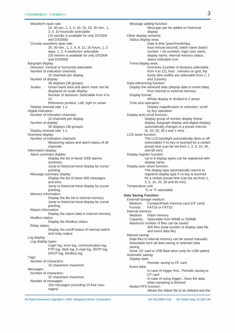
In case measurement ch = 8 ch, mathematical ch = 0 ch
Display data file (approx.)
Waveform span rate(time/div)
Data saving periodSampling time
30 s
1 s2 days
1 min
2 s4 days
2 min
4 s9 days
5 min
10 s23 days
10 min
20 s46 days
Event data file (approx.)
Data saving periodSampling time
2 s7 days
0.5 s46.3 h
1 s3 days
125 ms11.6 h
5 s19 days
10 s38 days
15 s
0.5 s27.8 h
25 ms2.3 h
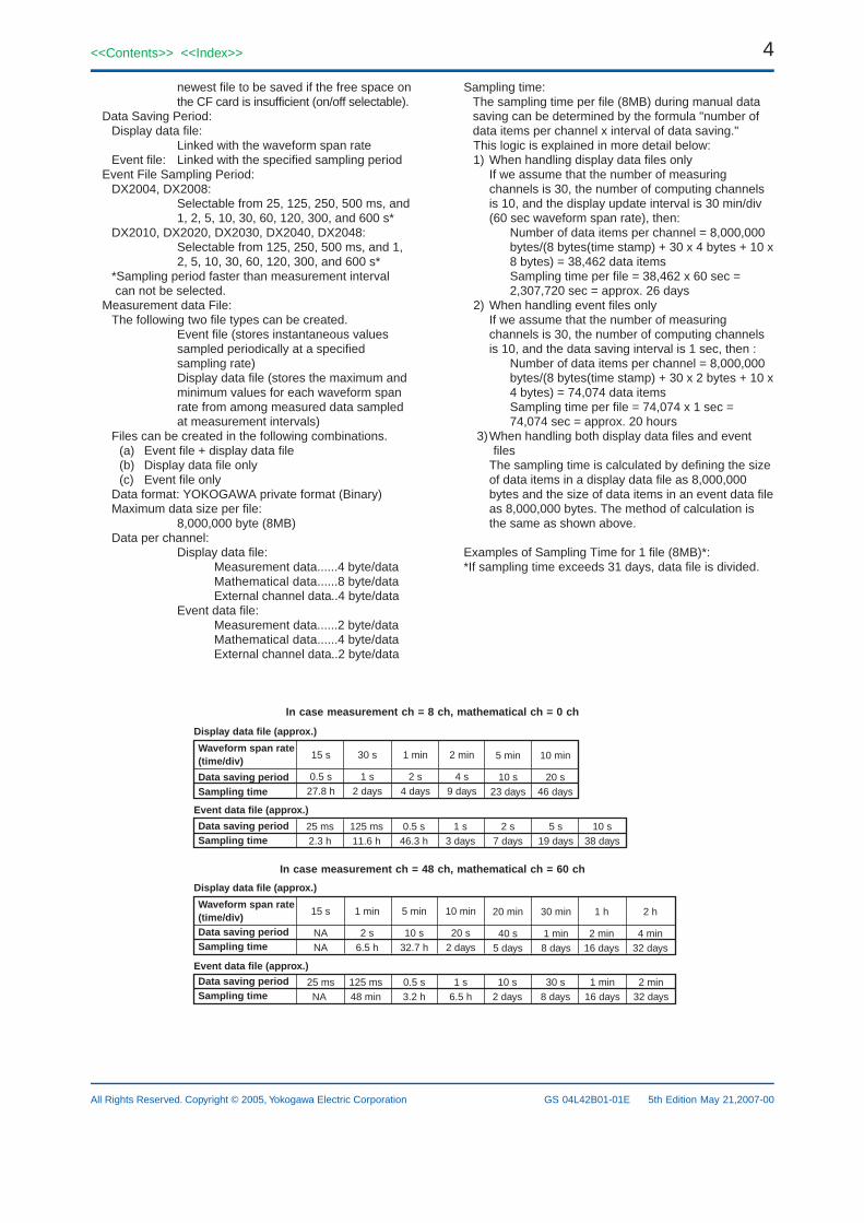
In case measurement ch = 48 ch, mathematical ch = 60 ch
Display data file (approx.)
Waveform span rate(time/div)Data saving periodSampling time
1 min
2 s6.5 h
5 min
10 s32.7 h
20 min
40 s5 days
30 min
1 min8 days
1 h
2 min16 days
Event data file (approx.)
Data saving periodSampling time
10 s2 days
0.5 s3.2 h
125 ms48 min
15 s
NANA
25 msNA
30 s8 days
1 min16 days
10 min
20 s2 days
2 h
4 min32 days
1 s6.5 h
2 min32 days
5<<Contents>> <<Index>>
All Rights Reserved. Copyright © 2005, Yokogawa Electric Corporation GS 04L42B01-01E 5th Edition May 21,2007-00
Manual sample data:The measuring and computing data can be savedmanually to the internal memory and CF card.Trigger: Key operation, communication command
or event action functionData format:
ASCIIMax. number of data:
400 data (if exceeds 400 data, oldest datais overwritten)
Report data (only for MATH option):Types: Hourly, daily, hourly + daily, daily + weekly,
and daily + monthlyData format:
ASCIIDrive: CF card
Trigger function:Selectable from FREE or TRIG for event data saving.Trigger mode:
Selectable from free, single or repeattrigger
Data length:Selectable from 10, 20, 30 min, 1, 2, 3, 4,6, 8, 12 hour, 1, 2, 3, 5, 7, 10, 14, 31 day
Pre trigger: Selectable from 0, 5, 25, 50, 75, 95, 100%Trigger source:
Key operation, communication commandor event action function
Display hard copy:Trigger: Key operation, communication command
or event action functionData format:
png formatDrive/output:
CF card or communication interfaceData file retrieving function:
Data file in CF card or USB flash drive (only for USBoption) can be retrieved and displayed.Retrieved data file:
Display data file or event data fileSaving and retrieving of configuration data:
Configuration information can be saved and retrievedas ASCII data.Drive: CF card or USB flash drive (only for USB
option)
Alarm FunctionNumber of alarm levels:
Up to four levels for each channelAlarm types:
High and low limits, differential high and lowlimits, high and low rate-of-change limits anddelay high and low
Alarm delay time:1 to 3600 s
Interval time of rate-of-change alarms:The measurement interval times 1 to 32
Display: The alarm status (type) is displayed in thedigital value display area upon occurrence ofan alarm. A common alarm indication is alsodisplayed.
Alarming behavior:non-hold or hold-type can be selectable forcommon to all channels.
Hysteresis: On/off selectable (common to measurementchannels, mathematical channels or externalchannels)0.0 to 5.0% of display span (or scaling span)
Outputs:
Output: Internal switch or relay output (optional)Number of internal switch:
30 pointsInternal switch action:
AND/ORNumber of relay output points:
2, 4, 6, 12, 22 or 24 points (optional)Relay action:
Energized/deenergized, hold/non-hold,AND/OR, alarm reflash selectable.
Alarm no logging function:When alarm occurs, only internal switch orrelay output is activated. There are noalarm display on screen and no record onalarm summary.On/off selectable for each channel andalarm level.
Memory:The times of alarm occurrences/recoveries, alarmtypes, etc. are stored in the memory.Up to 1000 latest alarm events are stored.
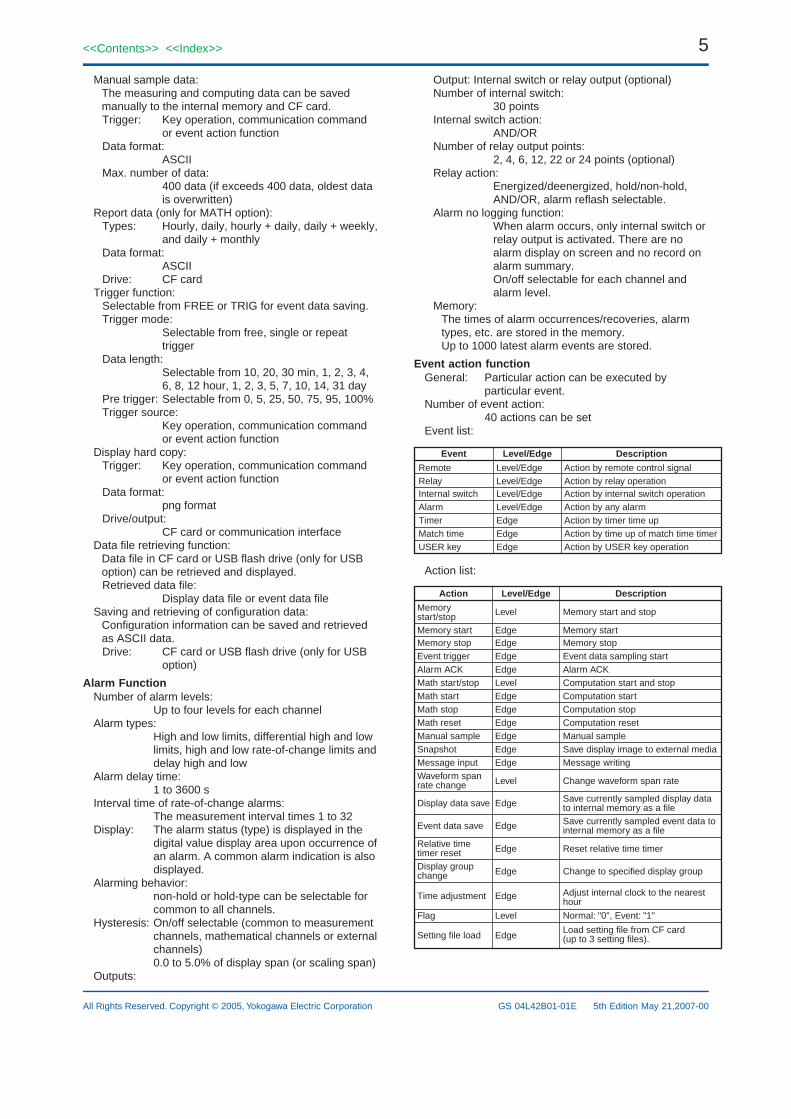
Event action functionGeneral: Particular action can be executed by
particular event.Number of event action:
40 actions can be setEvent list:
Level/Edge DescriptionEvent
RemoteRelayInternal switchAlarmTimerMatch timeUSER key
Level/EdgeLevel/EdgeLevel/EdgeLevel/EdgeEdgeEdgeEdge
Action by remote control signalAction by relay operationAction by internal switch operationAction by any alarmAction by timer time upAction by time up of match time timerAction by USER key operation
Action list:
Level/Edge DescriptionAction
Memory start/stopMemory startMemory stopEvent triggerAlarm ACKMath start/stop
Math stopMath reset
Level
EdgeEdgeEdgeEdgeLevelEdge
Memory start and stop
Memory startMemory stopEvent data sampling startAlarm ACKComputation start and stopComputation start
Edge Computation stop
Manual sampleEdge Computation reset
SnapshotEdge Manual sample
Message inputEdge Save display image to external media
Waveform span rate change
Edge Message writing
Display data save
Level Change waveform span rate
Event data save
Edge Save currently sampled display data to internal memory as a file
Relative time timer reset
Edge Save currently sampled event data to internal memory as a file
Display group change
Edge Reset relative time timer
Time adjustment
Edge Change to specified display group
Flag
Edge Adjust internal clock to the nearest hour
Setting file load EdgeLoad setting file from CF card(up to 3 setting files).
Math start
Level Normal: "0", Event: "1"
6
All Rights Reserved. Copyright © 2005, Yokogawa Electric Corporation
<<Contents>> <<Index>>
GS 04L42B01-01E 5th Edition May 21,2007-00
Security functionsGeneral: Login function or key lock function can be
set for each key operation or communicationoperation.
Key lock function:On/off and password can be set for eachoperation key and FUNC operation.
Login function:User name and password to login can be set.User level and number of users:
System administrator: 5 usersGeneral users: 30 users10 kinds of login mode can be set forgeneral users.
ClockClock: With calendar function (year of grace)Clock accuracy:
10 ppm, excluding a delay (of 1 second,maximum) caused each time the power isturned on.
Time setting method:Key operation, communication command,event action function or SNTP client function
Time adjustment method:During memory sample:
Adjust 40 ms per second (No influence formeasurement period)
During memory stop:Adjust at a time
Time zone:Time difference from GMT:
Settable from -1300 to 1300Date display format:
Selectable from YYYY/MM/DD, MM/DD/YYYY, DD/MM/YYYY or DD.MM.YYYY
DST function (summer/winter time):The time at which the daylight savings timeadjustment is automatically calculated andconfigured.
Communication FunctionsElectrical specifications:
Confirms to IEEE802.3 (DIX specification forEthernet frames)
Connection:Ethernet (10BASE-T)
Protocols: TCP, UDP, IP, ICMP, ARP, DHCP, HTTP,FTP, SMTP, SNTP, Modbus, DX private
E-mail inform function:E-mail is sent by events as below.
- Alarm occurring/alarm canceling- Recover from power failure- Memory end- Storage medium error, FTP client function error- Specified time period- Report data time up (only for mathematical option)
FTP client function:Data file auto-transfer from DXTransferred data file:
Display data file, event data file, reportdata file and display image file
FTP server function:File transfer from DX, file elimination,directory operation and file list output areavailable by request from host computer.
Web server function:Display image of DX and alarm informationcan be displayed on web browser software
SNTP client function:The time on DX can be synchronized to thetime of a SNTP server.
SNTP server function:The DX can operate as a SNTP server.
DHCP client function:Network address configuration can be obtainedautomatically from DHCP server.Obtained information:
IP address, subnet mask, default gatewayand DNS information
Modbus client function:Reading or writing of measurement data onother instruments are available by Modbusprotocol.Mathematical option or external input optionis required to read the data from otherinstruments.
Modbus server function:Output of measurement data from DX isavailable by Modbus protocol.
Setting/measurement server function:Operation, setting or output of measurementdata are available by DX private protocol.
Maintenance/test server function:Output connection information or networkinformation of the Ethernet communication.
Instrument information server function:Output instrument information such as serialnumber or model name of DX.
Batch functionGeneral: Data display and data management with
batch name, text field function and batchcomment function are available.
Batch name:Batch name can be used as file name of display data,event data and report data.Batch name format:
Batch number (max. 32 characters) + lotnumber (max. 8 characters)Use/not use selectable for lot number, on/off selectable for auto increment function
Text field function:Field number:
1 to 8Field title:
Max. 20 charactersField text:
Max. 30 charactersBatch comment function:
Batch comment is added to display data and eventdata.Batch comment information:
3 comments (max. 50 characters) areavailable.
7<<Contents>> <<Index>>
All Rights Reserved. Copyright © 2005, Yokogawa Electric Corporation GS 04L42B01-01E 5th Edition May 21,2007-00
Power SupplyRated power supply:
100 to 240 VAC (automatic switching)Allowable power supply voltage range:
90 to 132 or 180 to 264 VACRated power supply frequency:
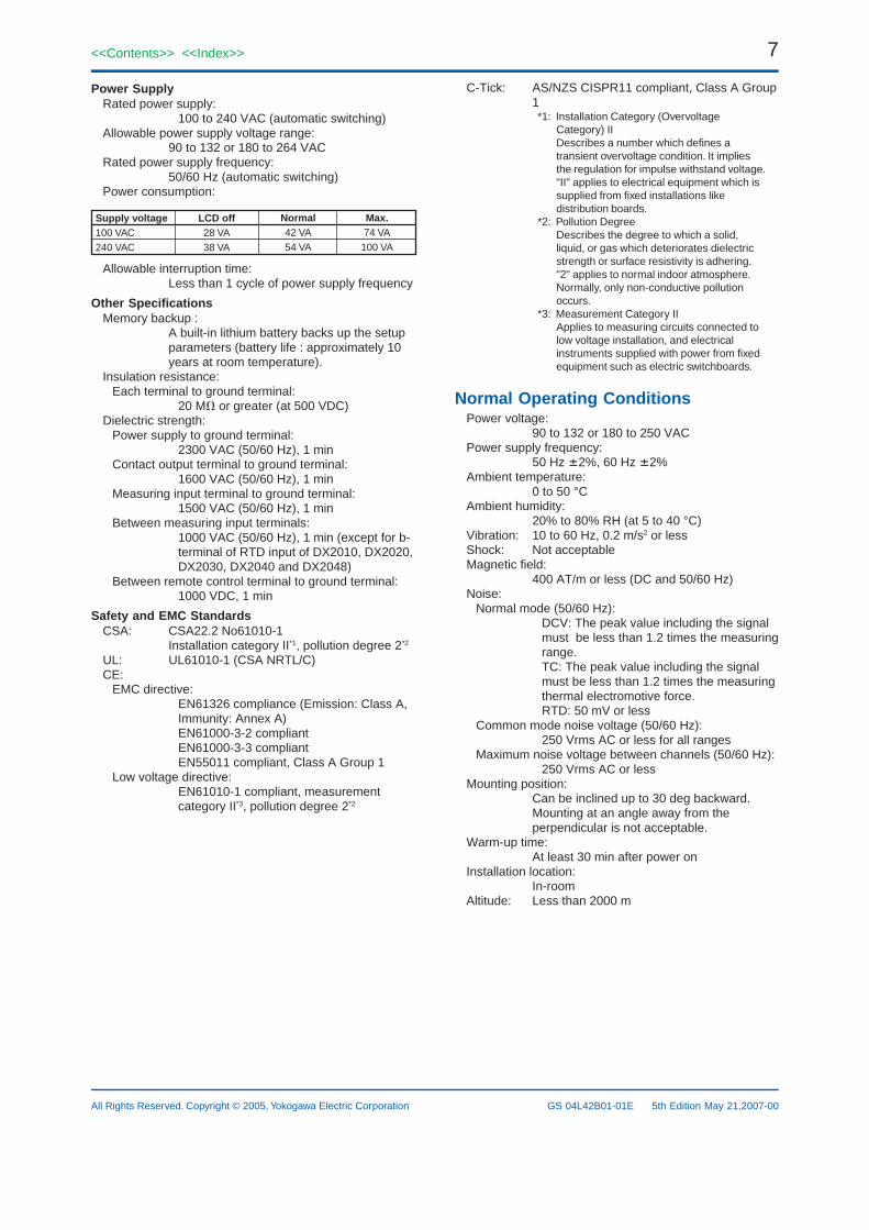
50/60 Hz (automatic switching)Power consumption:
Supply voltage100 VAC240 VAC
LCD off28 VA38 VA
Normal42 VA54 VA
Max.74 VA100 VA
Allowable interruption time:Less than 1 cycle of power supply frequency
Other SpecificationsMemory backup :
A built-in lithium battery backs up the setupparameters (battery life : approximately 10years at room temperature).
Insulation resistance:Each terminal to ground terminal:
20 M or greater (at 500 VDC)Dielectric strength:
Power supply to ground terminal:2300 VAC (50/60 Hz), 1 min
Contact output terminal to ground terminal:1600 VAC (50/60 Hz), 1 min
Measuring input terminal to ground terminal:1500 VAC (50/60 Hz), 1 min
Between measuring input terminals:1000 VAC (50/60 Hz), 1 min (except for b-terminal of RTD input of DX2010, DX2020,DX2030, DX2040 and DX2048)
Between remote control terminal to ground terminal:1000 VDC, 1 min
Safety and EMC StandardsCSA: CSA22.2 No61010-1
Installation category II*1, pollution degree 2*2
UL: UL61010-1 (CSA NRTL/C)CE:
EMC directive:EN61326 compliance (Emission: Class A,Immunity: Annex A)EN61000-3-2 compliantEN61000-3-3 compliantEN55011 compliant, Class A Group 1
Low voltage directive:EN61010-1 compliant, measurementcategory II*3, pollution degree 2*2
C-Tick: AS/NZS CISPR11 compliant, Class A Group1*1: Installation Category (Overvoltage
Category) IIDescribes a number which defines atransient overvoltage condition. It impliesthe regulation for impulse withstand voltage."II" applies to electrical equipment which issupplied from fixed installations likedistribution boards.
*2: Pollution DegreeDescribes the degree to which a solid,liquid, or gas which deteriorates dielectricstrength or surface resistivity is adhering."2" applies to normal indoor atmosphere.Normally, only non-conductive pollutionoccurs.
*3: Measurement Category IIApplies to measuring circuits connected tolow voltage installation, and electricalinstruments supplied with power from fixedequipment such as electric switchboards.
Normal Operating ConditionsPower voltage:
90 to 132 or 180 to 250 VACPower supply frequency:
50 Hz 2%, 60 Hz 2%Ambient temperature:
0 to 50 °CAmbient humidity:
20% to 80% RH (at 5 to 40 °C)Vibration: 10 to 60 Hz, 0.2 m/s2 or lessShock: Not acceptableMagnetic field:
400 AT/m or less (DC and 50/60 Hz)Noise:
Normal mode (50/60 Hz):DCV: The peak value including the signalmust be less than 1.2 times the measuringrange.TC: The peak value including the signalmust be less than 1.2 times the measuringthermal electromotive force.RTD: 50 mV or less
Common mode noise voltage (50/60 Hz):250 Vrms AC or less for all ranges
Maximum noise voltage between channels (50/60 Hz):250 Vrms AC or less
Mounting position:Can be inclined up to 30 deg backward.Mounting at an angle away from theperpendicular is not acceptable.
Warm-up time:At least 30 min after power on
Installation location:In-room
Altitude: Less than 2000 m
8
All Rights Reserved. Copyright © 2005, Yokogawa Electric Corporation
<<Contents>> <<Index>>
GS 04L42B01-01E 5th Edition May 21,2007-00
Standard PerformanceMeasuring and Recording Accuracy:
The following specifications apply to operation of the recorder under standard operation conditions.Temperature:
23 2 °CHumidity:
55% 10% RHPower supply voltage:
90 to 132 or 180 to 250 VACPower supply frequency:
50/60 Hz 1%Warm-up time:
At least 30 min.Other ambient conditions such as vibration should not adversely affect recorder operation.
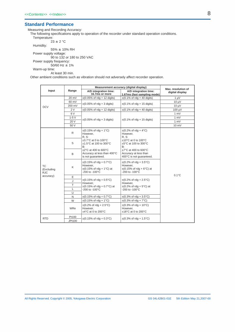
Input RangeMeasurement accuracy (digital display)
A/D integration time: 16.7ms or more
A/D integration time:1.67ms (fast sampling mode)
DCV
TC(ExcludingRJCaccuracy)
RTD
Max. resolution of digital display
1 µV10 µV10 µV100 µV1 mV1 mV1 mV
0.1°C
±(0.05% of rdg + 12 digits)
±(0.05% of rdg + 3 digits)
±(0.05% of rdg + 12 digits)
±(0.05% of rdg + 3 digits)
±(0.1% of rdg + 40 digits)
±(0.1% of rdg + 15 digits)
±(0.1% of rdg + 40 digits)
±(0.1% of rdg + 15 digits)
±(0.15% of rdg + 1°C)However,R, S:±3.7°C at 0 to 100°C±1.5°C at 100 to 300°CB:±2°C at 400 to 600°CAccuracy at less than 400°Cis not guaranteed.
±(0.2% of rdg + 4°C)However,R, S:±10°C at 0 to 100°C±5°C at 100 to 300°CB:±7°C at 400 to 600°CAccuracy at less than400°C is not guaranteed.
±(0.15% of rdg + 0.7°C)However,±(0.15% of rdg + 1°C) at-200 to -100°C
±(0.2% of rdg + 3.5°C)However,±(0.15% of rdg + 6°C) at-200 to -100°C
±(0.15% of rdg + 0.5°C)However,±(0.15% of rdg + 0.7°C) at-200 to -100°C
±(0.2% of rdg + 2.5°C)However,±(0.2% of rdg + 5°C) at-200 to -100°C
±(0.15% of rdg + 0.7°C) ±(0.3% of rdg + 3.5°C)±(0.15% of rdg + 1°C) ±(0.3% of rdg + 7°C)
±(0.2% of rdg + 2.5°C)However,±4°C at 0 to 200°C
±(0.3% of rdg + 10°C)However,±18°C at 0 to 200°C
20 mV60 mV200 mV
2 V6 V
1-5 V20 V
10 mV50 V
B
S
R
K
EJTLUNW
WRe
±(0.15% of rdg + 0.3°C) ±(0.3% of rdg + 1.5°C)Pt100JPt100
9<<Contents>> <<Index>>
All Rights Reserved. Copyright © 2005, Yokogawa Electric Corporation GS 04L42B01-01E 5th Edition May 21,2007-00
Measurement accuracy in case of scaling (digits):= measurement accuracy (digits) x scalingspan (digits)/measurement span (digits) + 2digitsDecimals are rounded off to the next highestnumber.
Reference junction compensation:INT (internal)/EXT (external) selectable(common for all channels)
Reference junction compensation accuracy:Types R, S, B, W, WRe: 1 °CTypes K, J, E, T, N, L, U: 0.5 °C(Above 0 °C, input terminal temperature isbalanced)
Maximum allowable input voltage: 60 VDC (continuous) for all input ranges
Input resistance:Approx. 10 M or more for DCV ranges of200 mVDC or less and TCApprox. 1 M for more than 2 VDC ranges
Input source resistance:DCV, TC: 2 k or lessRTD: 10 or less per wire (The resis-tance of all three wires must be equal.)
Input bias current:10 nA or less (approx. 100nA for TC rangewith burnout function)
Maximum common mode noise voltage:250 Vrms AC (50/60 Hz)
Maximum noise voltage between channels:250 Vrms AC (50/60 Hz)
Interference between channels:120 dB (when the input source resistance is500 and the inputs to other channels are60 V)
Common mode rejection ratio:A/D integration time 20 ms:
More than 120 dB (50 Hz 0.1%, 500 imbalance between the minus terminal andground)
A/D integration time 16.7 ms:More than 120 dB (60 Hz 0.1%, 500 imbalance between the minus terminal andground)
A/D integration time 1.67 ms:More than 80 dB (50/60 Hz 0.1%, 500 imbalance between the minus terminal andground)
Normal mode rejection ratio:A/D integration time 20 ms:
More than 40 dB (50 Hz 0.1%)A/D integration time 16.7 ms:
More than 40 dB (60 Hz 0.1%)A/D integration time 1.67 ms:
50/60Hz is not rejected.
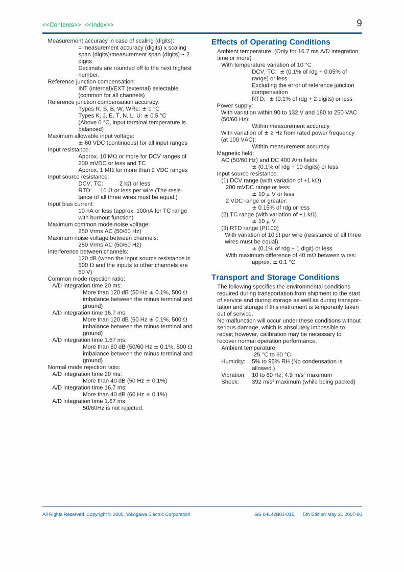
Effects of Operating ConditionsAmbient temperature: (Only for 16.7 ms A/D integrationtime or more)
With temperature variation of 10 °CDCV, TC: (0.1% of rdg + 0.05% ofrange) or lessExcluding the error of reference junctioncompensationRTD: (0.1% of rdg + 2 digits) or less
Power supply:With variation within 90 to 132 V and 180 to 250 VAC(50/60 Hz):
Within measurement accuracyWith variation of 2 Hz from rated power frequency(at 100 VAC):
Within measurement accuracyMagnetic field:
AC (50/60 Hz) and DC 400 A/m fields: (0.1% of rdg + 10 digits) or less
Input source resistance:(1) DCV range (with variation of +1 k)
200 mVDC range or less: 10 V or less
2 VDC range or greater: 0.15% of rdg or less
(2) TC range (with variation of +1 k) 10 V
(3) RTD range (Pt100)With variation of 10 per wire (resistance of all threewires must be equal):
(0.1% of rdg + 1 digit) or lessWith maximum difference of 40 m between wires:
approx. 0.1 °C
Transport and Storage ConditionsThe following specifies the environmental conditionsrequired during transportation from shipment to the startof service and during storage as well as during transpor-tation and storage if this instrument is temporarily takenout of service.No malfunction will occur under these conditions withoutserious damage, which is absolutely impossible torepair; however, calibration may be necessary torecover normal operation performance.
Ambient temperature:-25 °C to 60 °C
Humidity: 5% to 95% RH (No condensation isallowed.)
Vibration: 10 to 60 Hz, 4.9 m/s2 maximumShock: 392 m/s2 maximum (while being packed)
10
All Rights Reserved. Copyright © 2005, Yokogawa Electric Corporation
<<Contents>> <<Index>>
GS 04L42B01-01E 5th Edition May 21,2007-00
SPECIFICATIONS OF OPTIONAL FUNC-TIONS
Alarm Output Relays (/A1, /A2, /A3, /A4, /A5)An alarm signal is output from the rear panel as a relaycontact signal.Number or output:
Select from 2, 4, 6, 12 and 24 pointsRelay contact rating:
250 VDC/0.1 A (for resistance load), 250VAC (50/60 Hz)/3 A
Terminal configuration:SPDT (NO-C-NC). Energized-at-alarm/deenergized-at-alarm,AND/OR, and hold/non-hold actions areselectable.
Serial Communication Interface (/C2, /C3)Connection:
EIA RS-232 (/C2) or RS-422A/485 (/C3)Protocols: DX private protocol, Modbus(master/slave)
protocolSynchronization method:
Start-stop asynchronous transmissionConnection method (RS-422A/485):
4-wire half-duplex multi-drop connection(1 : N, N = 1 to 31)
Transmission speed:1200, 2400, 4800, 9600, 19200 or 38400bps
Data length:7 or 8 bits
Stop bit: 1 bitParity: Odd, even, or noneCommunication distance (RS-422A/485):
Up to 1.2 kmCommunication mode:
ASCII for input/output for control and settingASCII or binary for output of measured data
Setting/measurement server function:Operation, setting or output of measurementdata are available by DX private protocol.
Modbus communication:Reading or writing of measurement data onother instruments are available by Modbusprotocol.Mathematical function option or externalinput option is needed to read measurementdata from other instruments.
Operation mode:RTU MASTER or RTU SLAVE
Modbus master command number:1 to 16
VGA Video Output (/D5)Resolution: 640 x 480 pixels (VGA)Connector: 15 pins D-SUB (DB15HD)
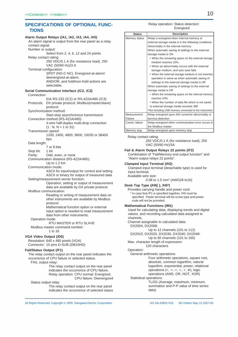
Fail/Status Output (/F1)The relay contact output on the rear panel indicates theoccurrence of CPU failure or selected status.
FAIL output relay:The relay contact output on the rear panelindicates the occurrence of CPU failure.Relay operation: CPU normal: Energized,
CPU failure: DeenergizedStatus output relay:
The relay contact output on the rear panelindicates the occurrence of selected status
Relay operation: Status detection:Energized
Status Description
Relay is energized when internal memory orexternal storage media is in the following conditions:Abnormality in the internal memoryWhen automatic saving of settings to the external storage media is ON
• When the remaining space on the external storage medium reaches 10%.
• When an abnormality occurs with the external storage medium, and auto save fails
• When the external storage medium is not inserted, operation is same as when automatic saving of settings to the external storage media is Off
When automatic saving of settings to the external storage media is Off
• When the remaining space on the internal memory reaches 10%
• When the number of data file which is not saved to external storage media exceeds 390
*Not including USB memory connected to the instrument.
Memory status
Relay energized upon A/D converter abnormality or burnout detection
MeasurementFailure
Relay energized when communication error occurs in the Modbus master .
Comm. failure
Relay energized upon memory stopMemory stop
Relay contact rating:250 VDC/0.1 A (for resistance load), 250VAC (50/60 Hz)/3A
Fail & Alarm Output Relays 22 points (/F2)Combination of "Fail/Memory end output function" and"Alarm output relays 22 points".
Clamped Input Terminal (/H2)Clamped input terminal (detachable type) is used forinput terminal.Available wire size:
0.08 to 1.5 mm2 (AWG28 to16)
Desk Top Type (/H5[ ], /H5*)Provides carrying handle and power cord.
* In case that /P1 is specified together, /H5 must bespecified. Power terminal will be screw type and powercode will not be provided.
Mathematical Functions (/M1)Used for calculating data, displaying trends and digitalvalues, and recording calculated data assigned tochannels.Channel assignable to calculated data:
DX2004, DX2008:Up to 12 channels (101 to 112)
DX2010, DX2020, DX2030, DX2040, DX2048:Up to 60 channels (101 to 160)
Max. character length of expression:120 characters
Operation:General arithmetic operations:
Four arithmetic operations, square root,absolute, common logarithm, naturallogarithm, exponential, power, relationaloperations (>, , <, , =, ), logicoperations (AND, OR, NOT, XOR)
Statistical operations:TLOG (Average, maximum, minimum,summation and P-P value of time seriesdata)
11<<Contents>> <<Index>>
All Rights Reserved. Copyright © 2005, Yokogawa Electric Corporation GS 04L42B01-01E 5th Edition May 21,2007-00
CLOG (Average, maximum, minimum,summation and P-P value of channelseries data)
Special operations:PRE (Previous data)HOLD(a):b (Hold data of "b" in case of "a"is not "0")RESET(a):b (Reset data of "b" and restartin case of "a" is not "0")CARRY(a):b (If "b" exceeds "a", "b-a"becomes computation results)
Conditional operation:[a?b:c] (Execute "b" in case of "a" is not"0", or execute "c" in case of "a" is "0")
Constant: Up to 60 constants (K01 to K60)Digital data input via communication:
Up to 60 data (C01 to C60)External input:
Up to 240 data (201 to 440) (only forexternal input option)
Remote status input:Remote input status (0/1) can be used in mathematicalexpression
Up to 8 inputs (D01 to D08)Pulse input:Up to 8 pulse count input (P01 to P08, Q01
to Q08) (only for pulse input option)Status input:
Internal switch status (S01 to S30), relaystatus (I01 to I36) and flag status (F01 to F08)can be used in mathematical expression
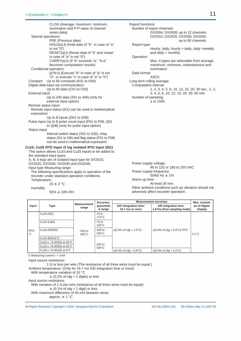
Cu10, Cu25 RTD Input /3 leg isolated RTD Input (/N1)This option allows Cu10 and Cu25 inputs to be added tothe standard input types.A, B, b legs are of isolated input type for DX2010,DX2020, DX2030, DX2040 and DX2048.Input type Measuring range:
The following specifications apply to operation of therecorder under standard operation conditions.Temperature:
23 2 °CHumidity:
55% 10% RH
Report functions:Number of report channels:
DX2004, DX2008: up to 12 channelsDX2010, DX2020, DX2030, DX2040:
up to 60 channelsReport type:
Hourly, daily, hourly + daily, daily +weeklyand daily + monthly
Operation:Max. 4 types are selectable from average,maximum, minimum, instantaneous andsummation
Data format:ASCII
Long term rolling average:Computation interval:
1, 2, 3, 4, 5, 6, 10, 12, 15, 20, 30 sec., 1, 2,3, 4, 5, 6, 10, 12, 15, 20, 30, 60 min
Number of sampling:1 to 1500
Power supply voltage:90 to 132 or 180 to 250 VAC
Power supply frequency:50/60 Hz 1%
Warm-up time:At least 30 min.
Other ambient conditions such as vibration should notadversely affect recorder operation.
Input Type Measurement range
Accuracy guarantee
d rangeA/D integration time:
16.7 ms or more
Measurement accuracyA/D integration time:
1.67ms (Fast sampling mode)
Max. resoluti on of digital
display
Cu10 (GE)
Cu10 (L&N)
Cu10 (WEED)
Cu10 (BAILEY)Cu10: =0.00392 at 20°CCu10: =0.00393 at 20°CCu25: =0.00425 at 0°C
-70 to 170°C
-75 to 150°C
-200 to 260°C
-200 to 300°C
-200 to 300°C
RTD*1 0.1°C
±(0.8% of rdg + 5.0°C) RTD±(0.4% of rdg + 1.0°C)
±(0.5% of rdg + 2.0°C)±(0.3% of rdg + 0.8°C)
*1 Measuring current: i = 1mA
Input source resistance:1 or less per wire (The resistance of all three wires must be equal.)
Ambient temperature: (Only for 16.7 ms A/D integration time or more)With temperature variation of 10 °C
(0.2% of rdg + 2 digits) or lessInput source resistance:
With variation of 1 per wire (resistance of all three wires must be equal): (0.1% of rdg + 1 digit) or less
With maximum difference of 40 m between wires:approx. 1 °C

12
All Rights Reserved. Copyright © 2005, Yokogawa Electric Corporation
<<Contents>> <<Index>>
GS 04L42B01-01E 5th Edition May 21,2007-00
3 legs Isolated RTD Input (/N2)A, B, b legs are of isolated input type.
* Can be specified only for DX2010, DX2020, DX2030,DX2040 and DX2048.A, B, b legs of DX2004 and DX2008 are isolated as standard.
Extended Input Types (/N3)This option allows extra inputs types to be added to thestandard input types.Input type Measuring range:
The following specifications apply to operation of therecorder under standard operation conditions.
Temperature:23 2 °C
Humidity: 55% 10% RHPower supply voltage:
90 to 132 or 180 to 250 VACPower supply frequency:
50/60 Hz 1%Warm-up time:
At least 30 min.Other ambient conditions such as vibration should notadversely affect recorder operation.
Input Type Measurement range A/D integration time:
16.7 ms or more
Kp vs Au7Fe 0.0 to 300.0K
0.0 to 1400.0°C
Within ±4.5K at 0 to 20KWithin ±2.5K at 20 to 300K
Within ±13.5K at 0 to 20KWithin ±7.5K at 20 to 300K
0.1 K
PLATINEL
PR40-20
NiNiMo
W/WRe
TypeN(AWG14)
Pt25
0.0 to 1310.0°C
0.0 to 2400.0°C
0.0 to 1300.0°C
-200.0 to 550.0°C
±(0.25% of rdg+0.7°C)
±(0.2% of rdg+1.3°C)
±15.0°C at 0 to 400°C±(0.2%of rdg+2.0°C) at 400to 2400°C
±(0.15% of rdg+0.6°C)
±(0.5% of rdg+3.5°C)
±(0.5% of rdg+7.0°C)
±30.0°C at 0 to 400°C±(0.4%of rdg+4.0°C) at 400to 2400°C
Pt50 -200.0 to 550.0°C ±(0.3% of rdg+0.6°C) ±(0.6% of rdg+3.0°C)Ni100(SAMA) -200.0 to 250.0°C ±(0.15% of rdg+0.4°C) ±(0.3% of rdg+2.0°C)Ni100(DIN) -60.0 to 180.0°C ±(0.15% of rdg+0.4°C) ±(0.3%of rdg+2.0°C)Ni120 -70.0 to 200.0°C ±(0.15% of rdg+0.4°C) ±(0.3% of rdg+2.0°C)
J263*B 0.0 to 300.0 KWithin ±3.0K at 0 to 40KWithin ±1.0K at 40 to 300K
Within ±9.0K at 0 to 40KWithin ±3.0K at 40 to 300K
Cu53 -50.0 to 150.0°C ±(0.15% of rdg+0.8°C) ±(0.3% of rdg+4.0°C)Cu100 -50.0 to 150.0°C ±(0.2% of rdg+1.0°C) ±(0.4% of rdg+5.0°C)
±(0.3% of rdg+3.0°C)
TC
RTD *1
±(0.25% of rdg+2.3°C)
Measurement accuracyA/D integration time:
1.67ms (Fast sampling mode)
Max. resoluti on of digital
display
0.1 K
0.1°C
0.1°C
±(0.25% of rdg+8.0°C)
0.0 to 1900.0°C
Accuracy is not guaranteedat 0 to 450°C±(0.9% of rdg+3.2°C) at450 to 750°C±(0.9% of rdg+1.3°C) at 750 to 1100°C±(0.9% of rdg+0.4°C) at1100 to 1900°C
Accuracy is not guaranteedat 0 to 450°C±(0.9% of rdg+15.0°C) at450 to 750°C±(0.9% of rdg+6.0°C) at750 to 1100°C±(0.9% of rdg+3.0°C) at1100 to 1900°C
*1 Measuring current: i = 1mA
Input source resistance:TC: 2 k or lessRTD: 1 or less per wire (The resistance ofall three wires must be equal.)
Ambient temperature: (Only for 16.7 ms A/D integrationtime or more)
With temperature variation of 10 °CTC: (0.1% of rdg + 0.05% of range) orless Excluding the error of reference junctioncompensation.RTD: (0.2% of rdg + 2 digits) or less
Input source resistance:(1) TC range (with variation of + 1 k) 10 µV(2) RTD range
With variation of 1 per wire (resistance of all threewires must be equal):
(0.1% of rdg + 1 digit) or lessWith maximum difference of 100 m between wires:
approx. 1 °C24 VDC/AC Power Supply (/P1)
Rated power supply: 24 VDC or 24 VAC (50/60Hz)Allowable power supply voltage range:
21.6 to 26.4 VDC/ACInsulation resistance:
Power supply to ground terminal: 20 M orgreater (at 500 VDC)
Dielectric strength:Power supply to ground terminal: 500 VAC
(50/60 Hz), 1 minMax. power consumption:
Supply voltage24 VDC24 VAC (50/60 Hz)
LCD off12 VA20 VA
Normal20 VA34 VA
Max.45 VA70 VA
Remote Control (/R1)This option allows eight functions to be controlledremotely by a contact input.Please refer the part of "Event action function" forfunctions to be controlled.
24 VDC transmitter power supply (/TPS4, /TPS8)Output voltage:
22.8 to 25.2 VDC (rated load current)Rated output current:
4 to 20 mADCMax. output current:
25 mADC (current to guard operationagainst overcurrent: approx. 68 mADC)
Allowable conductor resistance:RL (17.8 - transmitter minimum operationvoltage)/0.02 A (not include drop voltagewith load shunt resistance)
Max. length of wiring:2 km (CEV cable)
Insulation resistance:output terminal to grand terminal more than20 M (500 VDC)
13<<Contents>> <<Index>>
All Rights Reserved. Copyright © 2005, Yokogawa Electric Corporation GS 04L42B01-01E 5th Edition May 21,2007-00
Dielectric strength:Output terminal to grand terminal:
500 VAC (50/60 Hz, I = 10 mA), 1 minBetween output terminal:
500 VAC (50/60 Hz, I = 10 mA), 1 min
Easy text entry (/KB1, /KB2)Normal operating conditions:
Ambient temperature for usage:0 to 40 C
Ambient humidity for usage:20 to 80% RH (When 5 to 40 C, nocondensation)
Ambient temperature for storage:-10 to 60 C
Power supply:AA dry battery 2
Weight: Approx. 60 g (excluding dry battery)Dimensions: 170 (W) 50 (H) 23.7 (D) mmNumber of units that can be controlled:
Max. 32 units by ID settingCommunication distance:
Max. 8 m (depending on battery strengthand usage area)
Orientation specifications:Depends on battery strength & usage area
USB interface (/USB1)USB interface specification:
Based on Rev1.1, host functionNumber of ports:
2 ports (Front and rear panel)Power supply:
5V, 500mA (for each port)*1Available USB devices:
Keyboard: 104/89 keyboard (US) based on USB HIDClass Ver.1.1
External medium:USB flash drive (some of USB flash drivesmay not be supported by DXAdvanced)
*1: For low powered devices (bus power < 100 mA):5V 5%
For high powered devices (bus power < 500 mA):5V 10%
Devices which need more than 500 mA total bus powerfor 2 ports can not be connected at the same time.
Pulse input (/PM1)Pulse input option includes mathematical functionsoption (/M1) and remote control option (/R1).Number of inputs:
3 points (8 points are available in case ofusing remote inputs)
Input format:Photocoupler isolation (shared common)Isolated power supply for input terminal(approx. 5 V)
Input type:Non-voltage contact:
Close: 200 or less, Open: 100 k ormore
Open collector:ON: 0.5 V or less (30 mADC), Leakagecurrent of OFF: 0.25 mA or less
Counting: Counts rising edges of pulsesAllowable input voltage:
30 VDCMax. sampling pulse period:
Max.100 HzMinimum pulse length:
5 ms
Pulse detection period:Approx. 3.9 ms (256Hz)
Pulse measuring accuracy:1 pulse (for instantaneous mode)
Pulse count period:Counts the number of pulse per measure-ment period (P01 to P08) or per second(Q01 to Q08).
Calibration correction function (/CC1)Corrects the measurement value of each channel usingsegment linearizer approximation.Number of segment points:
2 to 16
External input function (/MC1)Digital input channels via communication or Modbusmaster function are extended to input data from otherinstruments*.Number of external input channels:
Up to 240 channels (channel number: 201 to 440)* Only for DX2010, DX2020, DX2030, DX2040 and DX2048* Fast sampling mode is not available with external input function option.
APPLICATION SOFTWAREDAQSTANDARD for DXAdvanced
Operating environmentOS: Microsoft Windows 2000/XPProcessor: Pentium II 333 MHz or higher (Pentium III
600 MHz or higher recommended)Memory: Free area of 32 MB or more (128 MB or
more recommended)Disk device:
CD-ROM drive that is applied to Windows2000/XP
Hard disk: Free area of at least 100 MBDisplay card:
Compatible with Windows 2000/XPCan display 32,000 colors or higher (64,000colors or higher recommended)
Printer: A printer and printer driver compatible withWindows 2000/XP
Basic function (packages)Configuration software:
External memory medium: configuration of setting andbasic setting modeConfiguration via communication: configuration ofsetting and basic setting mode without communicationconfiguration (ex. IP address)
Data viewer software:Numbers of display channels:
32 channels for each group, at most 50groups
Display function:Waveform display, digital display, circulardisplay, list display, report display etc.
File connection display:Connect data files that are dividedbecause of auto-save during continuousdata collecting or power failure, and thendisplay (can connect up to total 5 million)
Section computation:Maximum, minimum, average, effectiveand P-P value
Data conversion:File conversion to ASCII, Lotus 1-2-3 orMS-Excel format
Print out: Print out displayed data
14
All Rights Reserved. Copyright © 2005, Yokogawa Electric Corporation
<<Contents>> <<Index>>
GS 04L42B01-01E 5th Edition May 21,2007-00
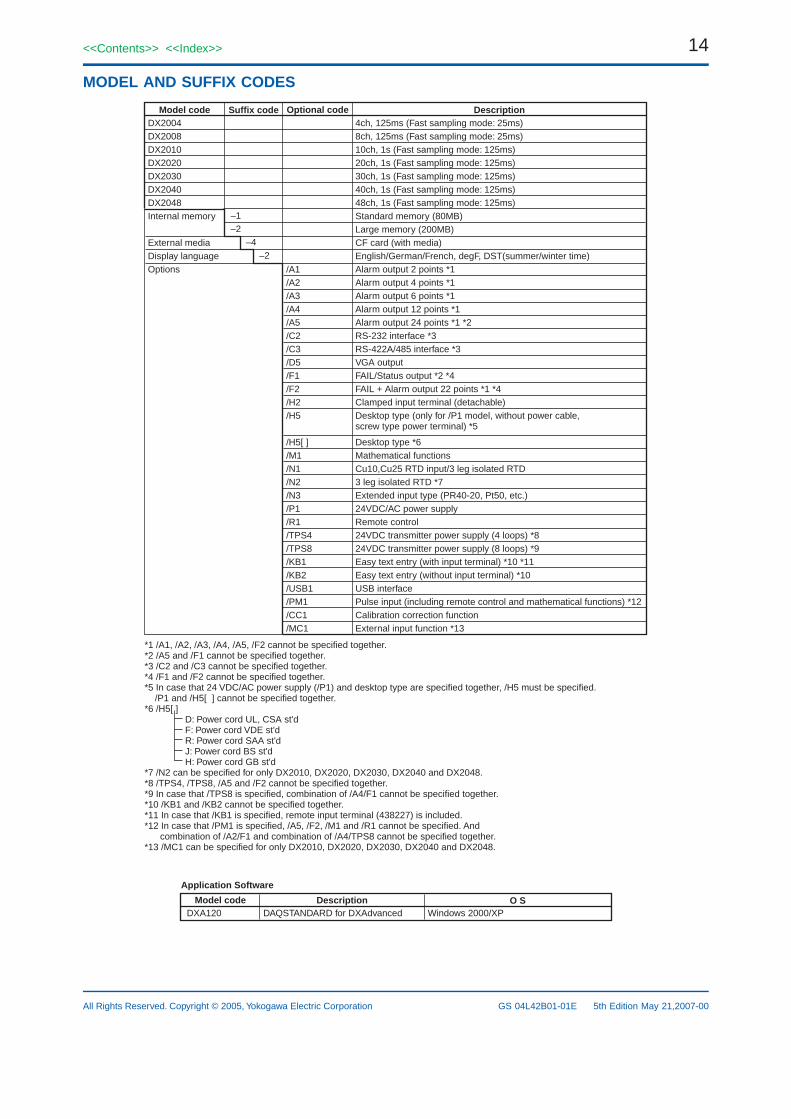
MODEL AND SUFFIX CODES
Suffix code DescriptionModel code Optional code
–2 –4
–1 –2
*1 /A1, /A2, /A3, /A4, /A5, /F2 cannot be specified together.*2 /A5 and /F1 cannot be specified together.*3 /C2 and /C3 cannot be specified together.*4 /F1 and /F2 cannot be specified together.*5 In case that 24 VDC/AC power supply (/P1) and desktop type are specified together, /H5 must be specified. /P1 and /H5[ ] cannot be specified together.*6 /H5[ ] D: Power cord UL, CSA st'd F: Power cord VDE st'd R: Power cord SAA st'd J: Power cord BS st'd H: Power cord GB st'd*7 /N2 can be specified for only DX2010, DX2020, DX2030, DX2040 and DX2048.*8 /TPS4, /TPS8, /A5 and /F2 cannot be specified together.*9 In case that /TPS8 is specified, combination of /A4/F1 cannot be specified together.*10 /KB1 and /KB2 cannot be specified together.*11 In case that /KB1 is specified, remote input terminal (438227) is included.*12 In case that /PM1 is specified, /A5, /F2, /M1 and /R1 cannot be specified. And combination of /A2/F1 and combination of /A4/TPS8 cannot be specified together.*13 /MC1 can be specified for only DX2010, DX2020, DX2030, DX2040 and DX2048.
4ch, 125ms (Fast sampling mode: 25ms)8ch, 125ms (Fast sampling mode: 25ms)10ch, 1s (Fast sampling mode: 125ms)20ch, 1s (Fast sampling mode: 125ms)30ch, 1s (Fast sampling mode: 125ms)40ch, 1s (Fast sampling mode: 125ms)48ch, 1s (Fast sampling mode: 125ms)Standard memory (80MB) Large memory (200MB)CF card (with media)English/German/French, degF, DST(summer/winter time)Alarm output 2 points *1Alarm output 4 points *1Alarm output 6 points *1Alarm output 12 points *1Alarm output 24 points *1 *2RS-232 interface *3RS-422A/485 interface *3VGA outputFAIL/Status output *2 *4FAIL + Alarm output 22 points *1 *4Clamped input terminal (detachable)Desktop type (only for /P1 model, without power cable,screw type power terminal) *5
Desktop type *6Mathematical functionsCu10,Cu25 RTD input/3 leg isolated RTD3 leg isolated RTD *7Extended input type (PR40-20, Pt50, etc.)24VDC/AC power supplyRemote control24VDC transmitter power supply (4 loops) *824VDC transmitter power supply (8 loops) *9Easy text entry (with input terminal) *10 *11Easy text entry (without input terminal) *10USB interfacePulse input (including remote control and mathematical functions) *12Calibration correction functionExternal input function *13
DX2004DX2008DX2010 DX2020 DX2030DX2040DX2048 Internal memory
External mediaDisplay languageOptions /A1
/A2/A3/A4/A5/C2/C3/D5/F1/F2/H2/H5
/H5[ ]/M1/N1/N2/N3/P1/R1/TPS4/TPS8/KB1/KB2/USB1/PM1/CC1/MC1
Description O SModel codeDXA120 DAQSTANDARD for DXAdvanced Windows 2000/XP
Application Software
15<<Contents>> <<Index>>
All Rights Reserved. Copyright © 2005, Yokogawa Electric Corporation GS 04L42B01-01E 5th Edition May 21,2007-00
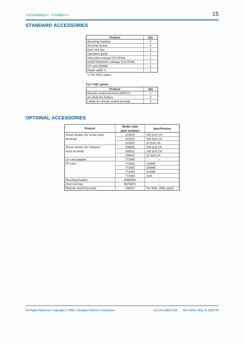
STANDARD ACCESSORIES
Product Qty
*1 For /H5[ ] option
Mounting bracketsTerminal screwsDoor lock keyOperation guideInstruction manual (CD-ROM)DAQSTANDARD software (CD-ROM)CF card (32MB)Power cable *1
25211111
Product QtyRemote control terminal (438227)AA alkali dry batteryLabels for remote control terminal
122
For / KB1 option
OPTIONAL ACCESSORIES
SpecificationProductModel code
(part number)250 Ω±0.1%100 Ω±0.1%10 Ω±0.1%250 Ω±0.1%100 Ω±0.1%10 Ω±0.1% –128MB256MB512MB1GB – –For /KB1, /KB2 option
Shunt resister (for screw inputterminal)
Shunt resister (for clampedinput terminal)
CF card adapterCF card
Mounting bracketDoor lock keyRemote control terminal
415920415921415922438920438921438922772090772091772092772093772094
B9900BXB8706FX438227
16
All Rights Reserved. Copyright © 2005, Yokogawa Electric Corporation
<<Contents>> <<Index>>
GS 04L42B01-01E 5th Edition May 21,2007-00
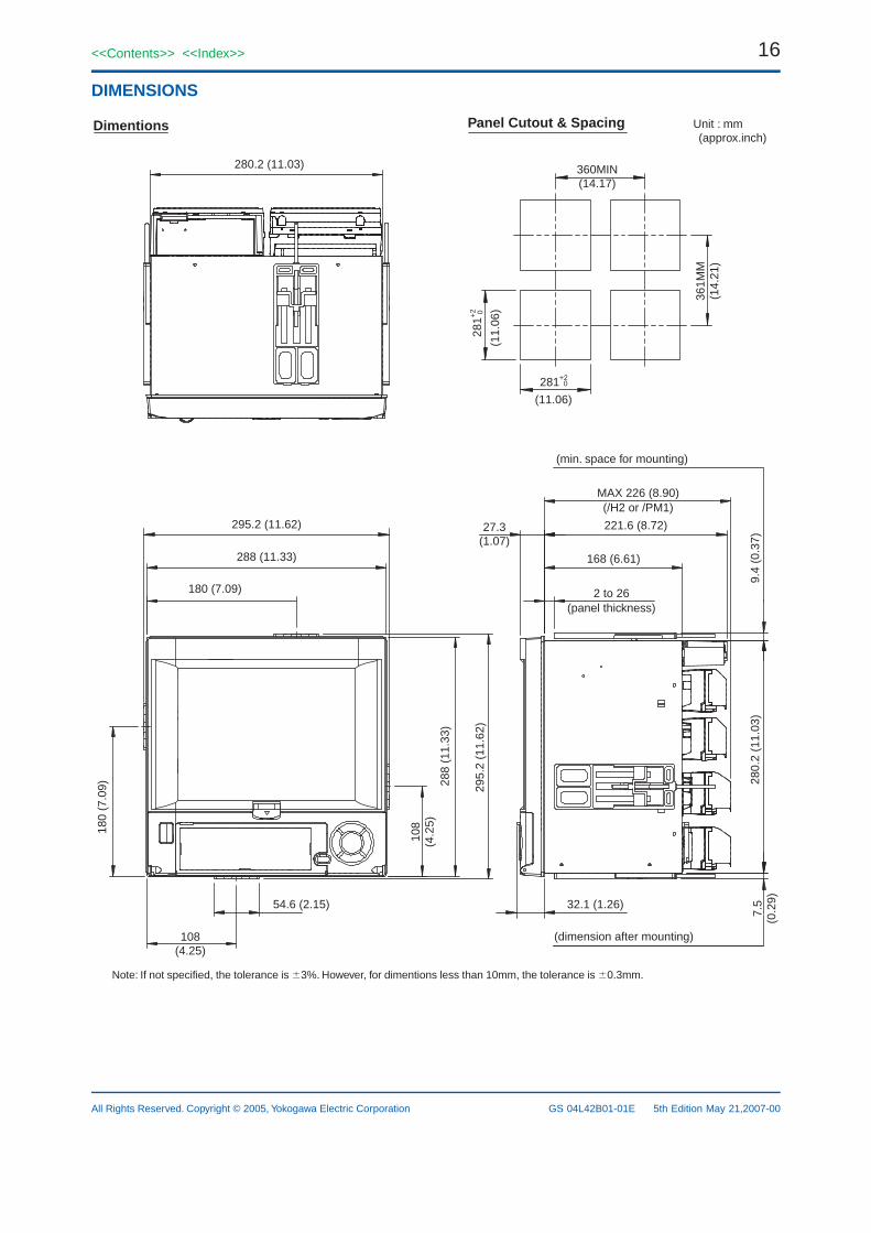
DIMENSIONS
280.2 (11.03)
295.2 (11.62)
288 (11.33)
180 (7.09)
180
(7.0
9)
108
(4.2
5)
54.6 (2.15)
108(4.25)
288
(11.
33)
295.
2 (1
1.62
)
360MIN(14.17)
281+2
0
361M
M(1
4.21
)
(11.06)
281+
2
0
(11.
06)
Dimentions Panel Cutout & Spacing Unit : mm (approx.inch)
MAX 226 (8.90)(/H2 or /PM1)
221.6 (8.72)
168 (6.61)
2 to 26(panel thickness)
27.3(1.07)
32.1 (1.26)
(dimension after mounting)
7.5
(0.2
9)28
0.2
(11.
03)
9.4
(0.3
7)
(min. space for mounting)
Note: If not specified, the tolerance is 3%. However, for dimentions less than 10mm, the tolerance is 0.3mm.
17<<Contents>> <<Index>>
All Rights Reserved. Copyright © 2005, Yokogawa Electric Corporation GS 04L42B01-01E 5th Edition May 21,2007-00
282.5 (11.12)
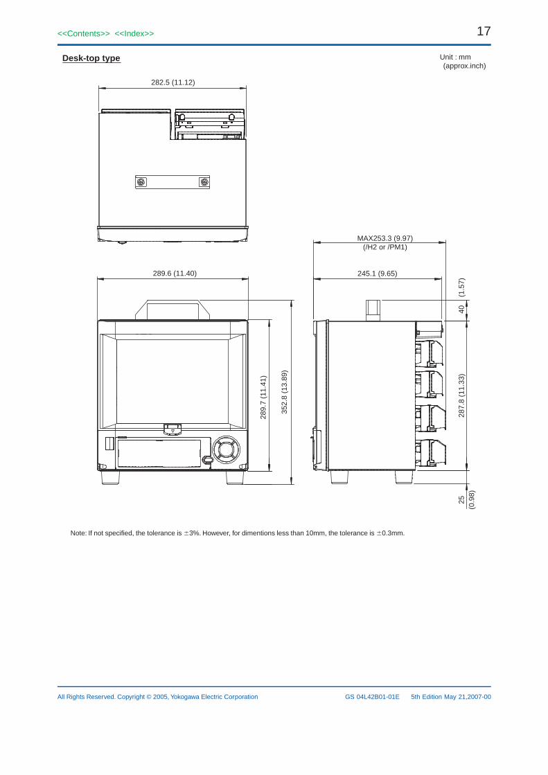
Desk-top type Unit : mm (approx.inch)
289.6 (11.40)
289.
7 (1
1.41
)
352.
8 (1
3.89
)
MAX253.3 (9.97)(/H2 or /PM1)
245.1 (9.65)
25(0
.98)
40
(1.
57)
287.
8 (1
1.33
)
Note: If not specified, the tolerance is 3%. However, for dimentions less than 10mm, the tolerance is 0.3mm.
18
All Rights Reserved. Copyright © 2005, Yokogawa Electric Corporation
<<Contents>> <<Index>>
GS 04L42B01-01E 5th Edition May 21,2007-00
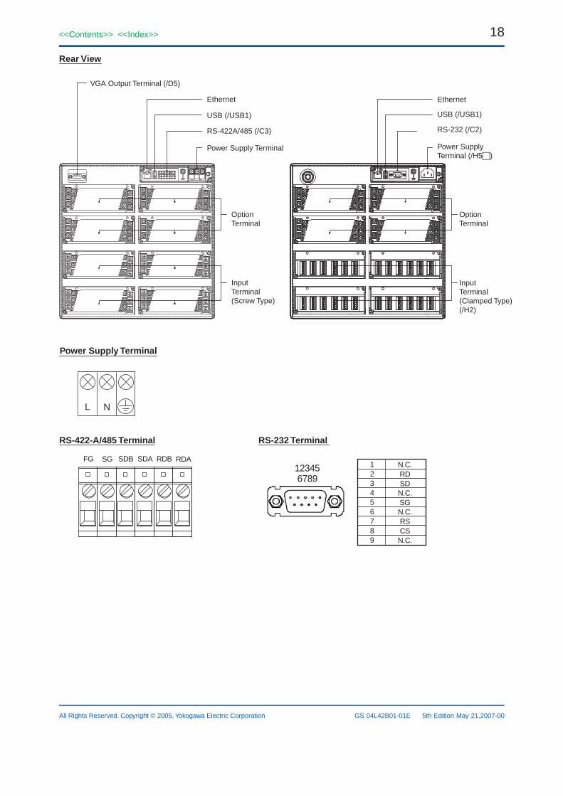
VGA Output Terminal (/D5)
Rear View
Ethernet
USB (/USB1)
Ethernet
USB (/USB1)
RS-422A/485 (/C3)
Power Supply Terminal
OptionTerminal
InputTerminal(Screw Type)
OptionTerminal
InputTerminal(Clamped Type)(/H2)
RS-232 (/C2)
Power SupplyTerminal (/H5)
RS-422-A/485 Terminal RS-232 Terminal
L N
FG SG SDB SDA RDB RDA123456789
N.C.RDSDN.C.SGN.C.RSCSN.C.
12345 6789
Power Supply Terminal
19<<Contents>> <<Index>>
All Rights Reserved. Copyright © 2005, Yokogawa Electric Corporation GS 04L42B01-01E 5th Edition May 21,2007-00
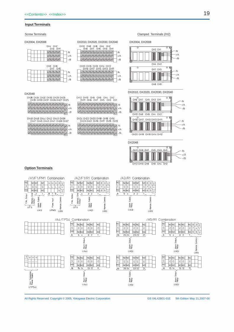
Input Terminals
Screw Terminals Clamped Terminals (/H2)
DX2010, DX2020, DX2030, DX2040
DX2048
DX2048
DX2010, DX2020, DX2030, DX2040DX2004, DX2008 DX2004, DX2008
Option Terminals
20
All Rights Reserved. Copyright © 2005, Yokogawa Electric Corporation
<<Contents>> <<Index>>
GS 04L42B01-01E 5th Edition May 21,2007-00
The TCP/IP software used in this product and the document for that TCP/IP software are based in part on BSD networking software, Release 1 licensed from The Regents of the University of California.• DAQSTATION and DXAdvanced are registered trademark of Yokogawa Electric Corporation.• Microsoft, MS and Windows are registered trademarks of Microsoft Corporation USA.• Lotus and 1-2-3 are registered trademark of Lotus Development Corporation.• Pentium are registered trademarks of Intel Corporation.• Ethernet is a registered trademark of XEROX Corporation.• Modbus is a registered trademark of AEG Schneider.• Other company and/or product names are registered trade mark of their manufactures.
Subject to change without notice