GENERAL CATALOGUE 50 Hz - Unitermuniterm.sk/res/pdf/dab.pdf2 CIRCULATORS: Performance range 1 SINGLE...
117
® PUMP PERFORMANCE GENERAL CATALOGUE 50 Hz
Transcript of GENERAL CATALOGUE 50 Hz - Unitermuniterm.sk/res/pdf/dab.pdf2 CIRCULATORS: Performance range 1 SINGLE...

®
P U M P P E R F O R M A N C E
GENERALCATALOGUE50 Hz
®
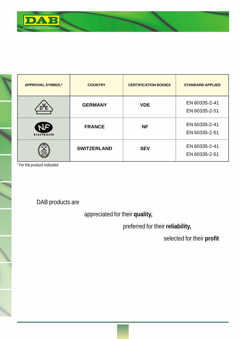
APPROVAL SYMBOL* COUNTRY CERTIFICATION BODIES STANDARD APPLIED
GERMANY VDE
FRANCE NF
SWITZERLAND SEV
EN 60335-2-41EN 60335-2-51
EN 60335-2-41EN 60335-2-51
EN 60335-2-41EN 60335-2-51
DVE
DAB products are
appreciated for their quality,
preferred for their reliability,
selected for their profit
*For the product indicated
®
1
1
2
3
4
5
6
7
8
9
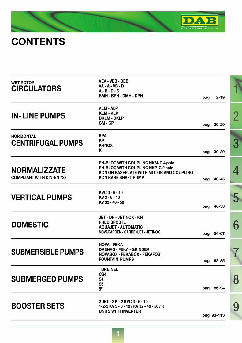
CONTENTS
CIRCULATORS
IN- LINE PUMPS
CENTRIFUGAL PUMPS
NORMALIZZATE
VERTICAL PUMPS
DOMESTIC
SUBMERSIBLE PUMPS
SUBMERGED PUMPS
BOOSTER SETS
VEA - VEB - DEBVA - A - VB - DA - B - D - SBMH - BPH - DMH - DPH
WET ROTOR
HORIZONTAL
COMPLIANT WITH DIN-EN 733
ALM - ALPKLM - KLPDKLM - DKLPCM - CP
KPAKPK-INOXK
EN-BLOC WITH COUPLING NKM-G 4 poleEN-BLOC WITH COUPLING NKP-G 2 poleKDN ON BASEPLATE WITH MOTOR AND COUPLINGKDN BARE SHAFT PUMP
KVC 3 - 6 - 10KV 3 - 6 - 10KV 32 - 40 - 50
JET - DP - JETINOX - KHPREDISPOSTEAQUAJET - AUTOMATICNOVAGARDEN - GARDENJET - JETINOX
NOVA - FEKADRENAG - FEKA - GRINDERNOVABOX - FEKABOX - FEKAFOSFOUNTAIN PUMPS
TURBINELCS4S4S65”
2 JET - 2 K - 2 KVC 3 - 6 - 101-2-3 KV 3 - 6 - 10 / KV 32 - 40 - 50 / KUNITS WITH INVERTER
pag. 2-19
pag. 20-29
pag. 30-39
pag. 40-45
pag. 46-53
pag. 54-67
pag. 68-85
pag. 86-94
pag. 93-113
3
4
5
6
7
8
9
®
2
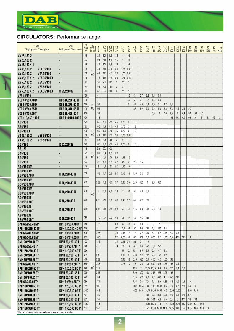
CIRCULATORS: Performance range
1
SINGLESingle-phase - Three-phase
TWINSingle-phase - Three-phase
P1MaxW
Qm3/h 0 0,6 1,2 1,8 2,4 3 4,2 5,4 7,2 9,6 12 14,4 18 24 30 36 42 54 72l/min 0 10 20 30 40 50 70 90 120 160 200 240 300 400 500 600 700 900 1200
80 1201333 2000
2,4 2,25 1,9 1,5 1 0,6
2,4 2,25 1,9 1,5 1 0,6
2,4 2,25 1,9 1,5 1 0,6
4,1 3,65 3,15 2,5 1,75 0,82
4,1 3,65 3,15 2,5 1,75 0,82
4,1 3,65 3,15 2,5 1,75 0,82
5,2 4,6 3,85 3 2,1 1
5,2 4,6 3,85 3 2,1 1
5,2 4,6 3,85 3 2,1 1
4 3,3 3 2,7 2,2 1,6 0,8
4 3,3 3 2,7 2,2 1,6 0,8
5,7 5 4,8 4,5 4,2 3,9 3,1 2,7 1,8
9,1 8,5 8,2 7,9 7,2 6,8 6,3 5,6 4,4 3,4 2,2
9,1 8,4 8 7,8 7,5 7 6,4 5,8 5,1 3,6
11,5 10,5 10,3 9,9 9,5 9 8 6,2 5,3 2
6,5 5,9 5,15 4,5 3,75 3 1,3
6,5 5,9 5,15 4,5 3,75 3 1,3
6,5 5,9 5,15 4,5 3,75 3 1,3
4,1 3,65 3,15 2,5 1,75 0,82
5,3 4,6 3,85 3 2,1 1
6,5 5,9 5,15 4,5 3,75 3 1,3
0,89 0,73 0,38
1,62 1,4 1,2 0,75
3,43 3,1 2,75 2,25 1,65 1,3
6,21 5,8 5,2 4,7 3,9 3 2,3 1,5
2 1,9 1,75 1,55 1,35 1,05
5,8 5,7 5,6 5,35 5,15 4,8 4,05 3,2 1,55
5,83 5,8 5,75 5,7 5,65 5,55 5,25 4,85 4 2,6 0,85
8 7,8 7,6 7,3 7 6,6 5,8 4,8 3,1
6,05 5,95 5,8 5,65 5,45 5,25 4,7 4,05 2,35
6,15 6,05 5,95 5,8 5,7 5,6 5,25 4,8 4,05 2,8 1,4
7,9 7,7 7,6 7,15 6,8 6,4 5,6 4,6 2,85
7,2 6,8 6,7 6,5 6,2 5,8 5 3,7 2
11 10,3 10,1 9,8 9,0 8,6 7,65 6,2 4,35 2,4
7,65 7,5 7,45 7,4 7,3 7,2 6,98 6,7 6,2 5,75 4,6 2,3
6,8 6,79 6,75 6,7 6,6 6,57 6,5 6,35 6,2 5,95 5,5 4,35 2,85 1,2
3,3 3,1 2,95 2,85 2,5 2,1 1,15
7,65 7,4 7,3 7,2 6,8 6,4 5,45 3,9 2,25
12 11 10,7 10,1 9,5 8,4 6,8 4,7 2,2
3,15 3,02 3 2,93 2,85 2,65 2,3 1,75 1,2
5,83 5,65 5,6 5,49 5,35 5,1 4,75 4,2 3,65 2,62
7,95 7,75 7,7 7,6 7,5 7,35 6,92 6,45 5,85 4,65 2,4
11,7 11,3 11 10,75 10,25 9,6 8,9 7,75 5,4 2,6
3,15 3,09 3,02 2,98 2,85 2,55 2,25 1,65
5,4 5,15 5,05 4,9 4,7 4,45 4,1 3,45 2,25
7,4 7,35 7,3 7,24 7,1 6,9 6,65 6,15 4,9 3,3 1,4
10,9 10,75 10,68 10,6 10,5 10,38 10,2 9,8 8,7 7,15 5,2 3
14,9 14,88 14,83 14,75 14,65 14,55 14,3 13,88 12,65 11 9,35 7,15
3,9 3,85 3,8 3,75 3,65 3,48 3,1 2,45 1,75
5,7 5,66 5,61 5,59 5,5 5,4 5 4,55 3,9 3,1
11,8 11,65 11,58 11,5 11,4 11,25 10,75 10,2 9,39 8,37 5,65
15,3 15,1 15,06 14,99 14,92 14,75 14,5 14 13,4 12,4 10,3 6
VA 25/130.2VA 25/180.2VA 25/180 X.2VA 35/130.2 VEA 35/130VA 35/180.2 VEA 35/180VA 35/180 X.2 VEA 35/180 XVA 55/130.2 VEA 55/130VA 55/180.2 VEA 55/180VA 55/180 X.2 VEA 55/180 XVEA 40/190VEB 40/250.40 MVEB 55/270.50 MVEB 90/340.65 MVEB 90/400.80 TVEB 110/450.100 TA 65/130A 65/180A 65/180 XVB 35/120.2 VEB 35/120VB 55/120.2 VEB 55/120B 65/120S 8/150S 16/150S 35/150S 65/150A 20/180 XMA 50/180 XMB 50/250.40 MA 56/180 XMB 56/250.40 MA 80/180 XMB 80/250.40 MA 50/180 XTB 50/250.40 TA 56/180 XTB 56/250.40 TA 80/180 XTB 80/250.40 TBPH 60/250.40 M*BPH 120/250.40 M*BPH 60/280.50 M*BPH 60/340.65 M*BMH 30/250.40 T*BPH 60/250.40 T*BPH 120/250.40 T*BMH 30/280.50 T*BMH 60/280.50 T*BPH 60/280.50 T*BPH 120/280.50 T*BMH 30/340.65 T*BMH 60/340.65 T*BPH 60/340.65 T*BPH 120/340.65 T*BPH 150/340.65 T*BMH 30/360.80 T*BMH 60/360.80 T*BPH 120/360.80 T*BPH 150/360.80 T*
--------D 55/220.32-DEB 40/250.40 MDEB 55/270.50 MDEB 90/340.65 MDEB 90/400.80 TDEB 110/450.100 T
----D 65/220.32-----
D 50/250.40 M
D 56/250.40 M
D 80/250.40 M
D 50/250.40 T
D 56/250.40 T
D 80/250.40 T
DPH 60/250.40 M*DPH 120/250.40 M*DPH 60/280.50 M*DPH 60/340.65 M*DMH 30/250.40 T*DPH 60/250.40 T*DPH 120/250.40 T*DMH 30/280.50 T*DMH 60/280.50 T*DPH 60/280.50 T*DPH 120/280.50 T*DMH 30/340.65 T*DMH 60/340.65 T*DPH 60/340.65 T*DPH 120/340.65 T*DPH 150/340.65 T*DMH 30/360.80 T*DMH 30/360.80 T*DPH 120/360.80 T*DPH 150/360.80 T*
H(m)
H(m)
H(m)
H(m)
H(m)
H(m)
55
55
55
78
78
78
91
91
91
120
120
230
120
250
400
125
125
125
78
91
125
46
67
66
124
78
156
255
236
250
310
285
316
510
595
735
192
348
536
255
410
589
898
270
445
756
1275
2800
484
763
1820
2710* Hydraulic values refer to maximum speed and single models.
®
3
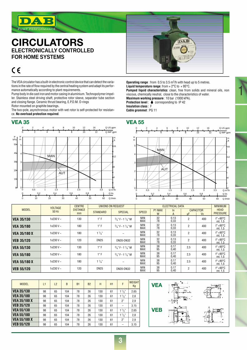
CIRCULATORSELECTRONICALLY CONTROLLEDFOR HOME SYSTEMS
The VEA circulator has a built-in electronic control device that can detect the varia-tions in the rate of flow required by the central heating system and adapt its perfor-mance automatically according to plant requirements.Pump body in die cast iron and motor casing in aluminium. Technopolymer impel-ler. Stainless steel driving shaft, protective rotor sleeve, separator tube sectionand closing flange. Ceramic thrust bearing, E.P.D.M. O-ringsRotor mounted on graphite bearings.The two-pole, asynchronous motor with wet rotor is self-protected for resistan-ce. No overload protection required.
Operating range : from 0.5 to 3.5 m3/h with head up to 5 metres.Liquid temperature range: from + 2°C to + 95°C.Pumped liquid characteristics: clean, free from solids and mineral oils, nonviscous, chemically neutral, close to the characteristics of water.Maximum working pressure : 10 bar (1000 kPA).Protection level : corresponding to IP 42Insulation class : FCable grommet : PG 11
0 0,5 1 1,5 2 2,5 3 3,5 Q m3/h0
1
2
3
4
5
Hm
0
10
20
30
40
50
PkPa
0 10 20 30 40 50 60 Q l/min
0 0,2 0,4 0,6 0,8 1 Q l/s
0
4
8
12
16
H ft
0 2 4 6 8 10 12 16 Q US gpm
0 2 4 6 8 10 12 Q IMP gpm
MAN
AUT
0 0,5 1 1,5 2 2,5 3 3,5 Q m3/h0
1
2
3
4
5
Hm
0 10 20 30 40 50 60 Q l/min
0 0,2 0,4 0,6 0,8 1 Q l/s
0
4
8
12
16
H ft
0 2 4 6 8 10 12 16 Q US gpm
0 2 4 6 8 10 12 Q IMP gpm
MAN
AUT
VEA 35 VEA 55
VEA
VEB
MODEL
VEA 35/130
VEA 35/180
VEA 35/180 X
VEB 35/120
VEA 55/130
VEA 55/180
VEA 55/180 X
VEB 55/120
VOLTAGE50 Hz
1x230 V ~
1x230 V ~
1x230 V ~
1x230 V ~
1x230 V ~
1x230 V ~
1x230 V ~
1x230 V ~
130
180
180
120
130
180
180
120
1” F
1” F
1 1/4”
DN25
1” F
1” F
1 1/4”
DN25
3/4” F - 1 1/4” M
3/4” F - 1 1/4” M
–
DN20-DN32
3/4” F - 1 1/4” M
3/4” F - 1 1/4” M
–
DN20-DN32
MINMAXMINMAXMINMAXMINMAXMINMAXMINMAXMINMAXMINMAX
32783278327832783895389538953895
0,130,330,130,330,130,330,130,330,170,400,170,400,170,400,170,40
t° +90°Cmt. 1,5
t° +90°Cmt. 1,5
t° +90°Cmt. 1,5
t° +90°Cmt. 1,5
t° +90°Cmt. 1,5
t° +90°Cmt. 1,5
t° +90°Cmt. 1,5
t° +90°Cmt. 1,5
2
2
2
2
2,5
2,5
2,5
2
400
400
400
400
400
400
400
400
CENTREDISTANCE
mm
MINIMUMHEAD
PRESSURE
UNIONS ON REQUEST
STANDARD SPECIAL
ELECTRICAL DATA
SPEED P1 MAXW
InA
CAPACITORµF Vc
VEA 35/130 98 65 104 78 26 130 61 1 1/2” 2,65
VEA 35/180 98 65 104 78 26 130 61 1 1/2” 2,8
VEA 35/180 X 98 65 104 78 26 130 61 2” 2,9
VEB 35/120 98 65 104 78 26 130 61 – 3,15
VEA 55/130 98 65 104 78 26 130 61 1 1/2” 2,65
VEA 55/180 98 65 104 78 26 130 61 1 1/2” 2,8
VEA 55/180 X 98 65 104 78 26 130 61 2” 2,9
VEB 55/120 98 65 104 78 26 130 61 – 3,15
MODEL L1 L2 B B1 B2 H H1 F WEIGHTKg
1
1
®
4
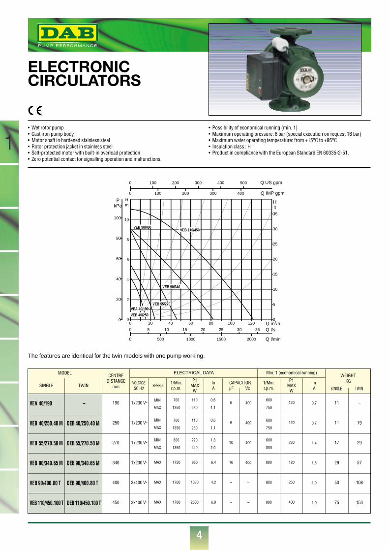
ELECTRONICCIRCULATORS
• Wet rotor pump• Cast iron pump body• Motor shaft in hardened stainless steel• Rotor protection jacket in stainless steel• Self-protected motor with built-in overload protection• Zero potential contact for signalling operation and malfunctions.
• Possibility of economical running (min. 1)• Maximum operating pressure: 6 bar (special execution on request 16 bar)• Maximum water operating temperature: from +15°C to +95°C• Insulation class : H• Product in compliance with the European Standard EN 60335-2-51.
0 Q m3/h0
2
4
6
8
10
Hm
0
20
40
60
80
100
PkPa
0 500 1000 1500 2000 Q l/min
0 5 10 15 20 25 30 35 Q l/s
0
5
10
15
20
25
30
35
H ft
0 100 200 300 400 500 Q US gpm
0 100 200 300 400 Q IMP gpm
20 40 60 80 100 120
VEB 110/450VEB 90/400
VEB 90/340
VEB 55/270VEA 40/190VEB 40/250
The features are identical for the twin models with one pump working.
CAPACITORµF Vc
InA
MODEL
SINGLE TWIN
VEA 40/190
VEB 40/250.40 M
VEB 55/270.50 M
VEB 90/340.65 M
VEB 90/400.80 T
VEB 110/450.100 T
–
DEB 40/250.40 M
DEB 55/270.50 M
DEB 90/340.65 M
DEB 90/400.80 T
DEB 110/450.100 T
SPEED1/Min.r.p.m.
P1MAX
W
InA
1/Min.r.p.m.
P1MAX
W
CENTREDISTANCE
mm
190
250
270
340
400
450
11
11
17
29
50
75
–
19
29
57
108
153
1x230 V˜
1x230 V˜
1x230 V˜
1x230 V˜
3x400 V˜
3x400 V˜
MAX
MAX
MAX
WEIGHTKG
SINGLE TWIN
ELECTRICAL DATA
VOLTAGE50 Hz
1750
1700
1700
MIN
MAX
MIN
MAX
MIN
MAX
800
1350
700
1350
700
1350
220
440
110
230
110
230
600
800
600
750
600
750
1,3
2,0
0,6
1,1
0,6
1,1
950
1630
2800
800
800
800
6,4
4,2
6,0
6
6
10
16
–
–
400
400
400
400
–
–
120
120
230
120
250
400
0,7
0,7
1,4
1,8
1,0
1,0
Min. 1 (economical running)
®
5
1
VEB 55/270.50 MVEB 40/250.40 MVEA 40/190
VEB 90/340.65 M VEB 90/400.80 T VEB 110/450.100 T
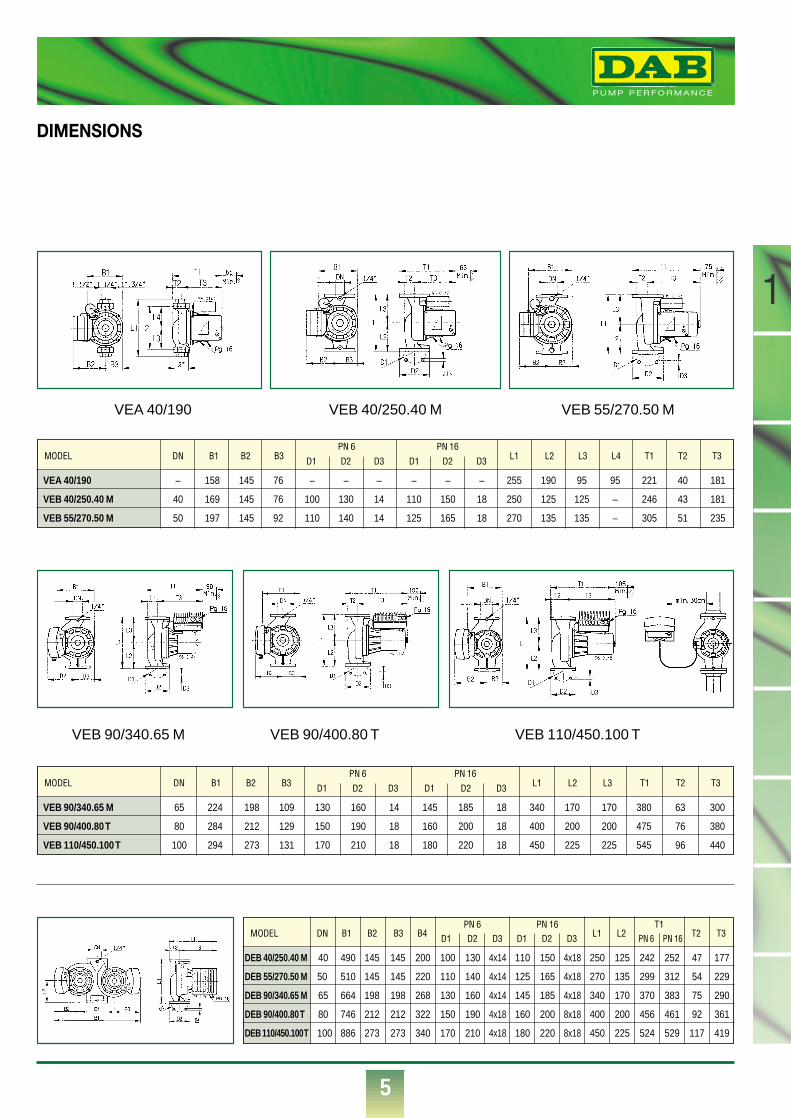
MODEL DN B1 B2 B3 B4 D1 D2 D3 D1 D2 D3 L1 L2 PN 6 PN 16 T2 T3
MODEL DN B1 B2 B3 D1 D2 D3 D1 D2 D3 L1 L2 L3 T1 T2 T3
VEB 90/340.65 M
VEB 90/400.80 T
VEB 110/450.100 T
65 224 198 109 130 160 14 145 185 18 340 170 170 380 63 300
80 284 212 129 150 190 18 160 200 18 400 200 200 475 76 380
100 294 273 131 170 210 18 180 220 18 450 225 225 545 96 440
PN 6 PN 16
MODEL DN B1 B2 B3 D1 D2 D3 D1 D2 D3 L1 L2 L3 L4 T1 T2 T3
VEA 40/190
VEB 40/250.40 M
VEB 55/270.50 M
– 158 145 76 – – – – – – 255 190 95 95 221 40 181
40 169 145 76 100 130 14 110 150 18 250 125 125 – 246 43 181
50 197 145 92 110 140 14 125 165 18 270 135 135 – 305 51 235
PN 6 PN 16
T1PN 6 PN 16
DEB 40/250.40 M
DEB 55/270.50 M
DEB 90/340.65 M
DEB 90/400.80 T
DEB 110/450.100 T
40 490 145 145 200 100 130 4x14 110 150 4x18 250 125 242 252 47 177
50 510 145 145 220 110 140 4x14 125 165 4x18 270 135 299 312 54 229
65 664 198 198 268 130 160 4x14 145 185 4x18 340 170 370 383 75 290
80 746 212 212 322 150 190 4x18 160 200 8x18 400 200 456 461 92 361
100 886 273 273 340 170 210 4x18 180 220 8x18 450 225 524 529 117 419
DIMENSIONS
®
6
1
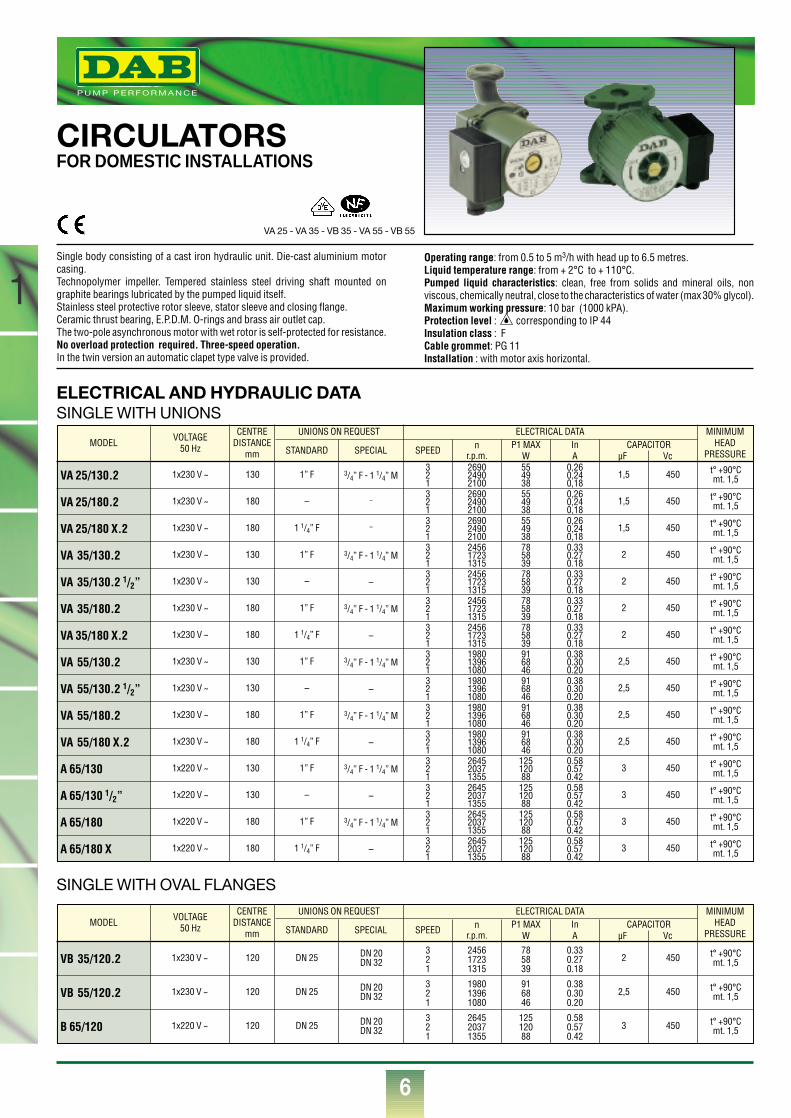
CIRCULATORSFOR DOMESTIC INSTALLATIONS
SINGLE WITH OVAL FLANGES
ELECTRICAL AND HYDRAULIC DATASINGLE WITH UNIONS
Single body consisting of a cast iron hydraulic unit. Die-cast aluminium motorcasing.Technopolymer impeller. Tempered stainless steel driving shaft mounted ongraphite bearings lubricated by the pumped liquid itself.Stainless steel protective rotor sleeve, stator sleeve and closing flange.Ceramic thrust bearing, E.P.D.M. O-rings and brass air outlet cap.The two-pole asynchronous motor with wet rotor is self-protected for resistance.No overload protection required. Three-speed operation.In the twin version an automatic clapet type valve is provided.
Operating range: from 0.5 to 5 m3/h with head up to 6.5 metres.Liquid temperature range: from + 2°C to + 110°C.Pumped liquid characteristics: clean, free from solids and mineral oils, nonviscous, chemically neutral, close to the characteristics of water (max 30% glycol).Maximum working pressure: 10 bar (1000 kPA).Protection level : corresponding to IP 44Insulation class : FCable grommet: PG 11Installation : with motor axis horizontal.
MODEL
VA 25/130.2
VA 25/180.2
VA 25/180 X.2
VA 35/130.2
VA 35/130.2 1/2”
VA 35/180.2
VA 35/180 X.2
VA 55/130.2
VA 55/130.2 1/2”
VA 55/180.2
VA 55/180 X.2
A 65/130
A 65/130 1/2”
A 65/180
A 65/180 X
VOLTAGE50 Hz
1x230 V ~
1x230 V ~
1x230 V ~
1x230 V ~
1x230 V ~
1x230 V ~
1x230 V ~
1x230 V ~
1x230 V ~
1x230 V ~
1x230 V ~
1x220 V ~
1x220 V ~
1x220 V ~
1x220 V ~
130
180
180
130
130
180
180
130
130
180
180
130
130
180
180
1” F
–
1 1/4” F
1” F
–
1” F
1 1/4” F
1” F
–
1” F
1 1/4” F
1” F
–
1” F
1 1/4” F
3/4” F - 1 1/4” M
–
–
3/4” F - 1 1/4” M
–
3/4” F - 1 1/4” M
–
3/4” F - 1 1/4” M
–
3/4” F - 1 1/4” M
–
3/4” F - 1 1/4” M
–
3/4” F - 1 1/4” M
–
321321321321321321321321321321321321321321321
269024902100269024902100269024902100245617231315245617231315245617231315245617231315198013961080198013961080198013961080198013961080264520371355264520371355264520371355264520371355
55493855493855493878583978583978583978583991684691684691684691684612512088125120881251208812512088
0,260,240,180,260,240,180,260,240,180.330.270.180.330.270.180.330.270.180.330.270.180.380.300.200.380.300.200.380.300.200.380.300.200.580.570.420.580.570.420.580.570.420.580.570.42
t° +90°Cmt. 1,5
t° +90°Cmt. 1,5
t° +90°Cmt. 1,5
t° +90°Cmt. 1,5
t° +90°Cmt. 1,5
t° +90°Cmt. 1,5
t° +90°Cmt. 1,5
t° +90°Cmt. 1,5
t° +90°Cmt. 1,5
t° +90°Cmt. 1,5
t° +90°Cmt. 1,5
t° +90°Cmt. 1,5
t° +90°Cmt. 1,5
t° +90°Cmt. 1,5
t° +90°Cmt. 1,5
1,5
1,5
1,5
2
2
2
2
2,5
2,5
2,5
2,5
3
3
3
3
450
450
450
450
450
450
450
450
450
450
450
450
450
450
450
CENTREDISTANCE
mm
MINIMUMHEAD
PRESSURE
UNIONS ON REQUEST
STANDARD SPECIAL
ELECTRICAL DATA
SPEED nr.p.m.
P1 MAXW
InA
CAPACITORµF Vc
MODEL
VB 35/120.2
VB 55/120.2
B 65/120
VOLTAGE50 Hz
1x230 V ~
1x230 V ~
1x220 V ~
120
120
120
DN 25
DN 25
DN 25
321
321
321
245617231315
198013961080
264520371355
785839
916846
12512088
0.330.270.18
0.380.300.20
0.580.570.42
t° +90°Cmt. 1,5
t° +90°Cmt. 1,5
t° +90°Cmt. 1,5
DN 20DN 32
DN 20DN 32
DN 20DN 32
2
2,5
3
450
450
450
CENTREDISTANCE
mm
MINIMUMHEAD
PRESSURE
UNIONS ON REQUEST
STANDARD SPECIAL
ELECTRICAL DATA
SPEED nr.p.m.
P1 MAXW
InA
CAPACITORµF Vc
VA 25 - VA 35 - VB 35 - VA 55 - VB 55
®
7
1
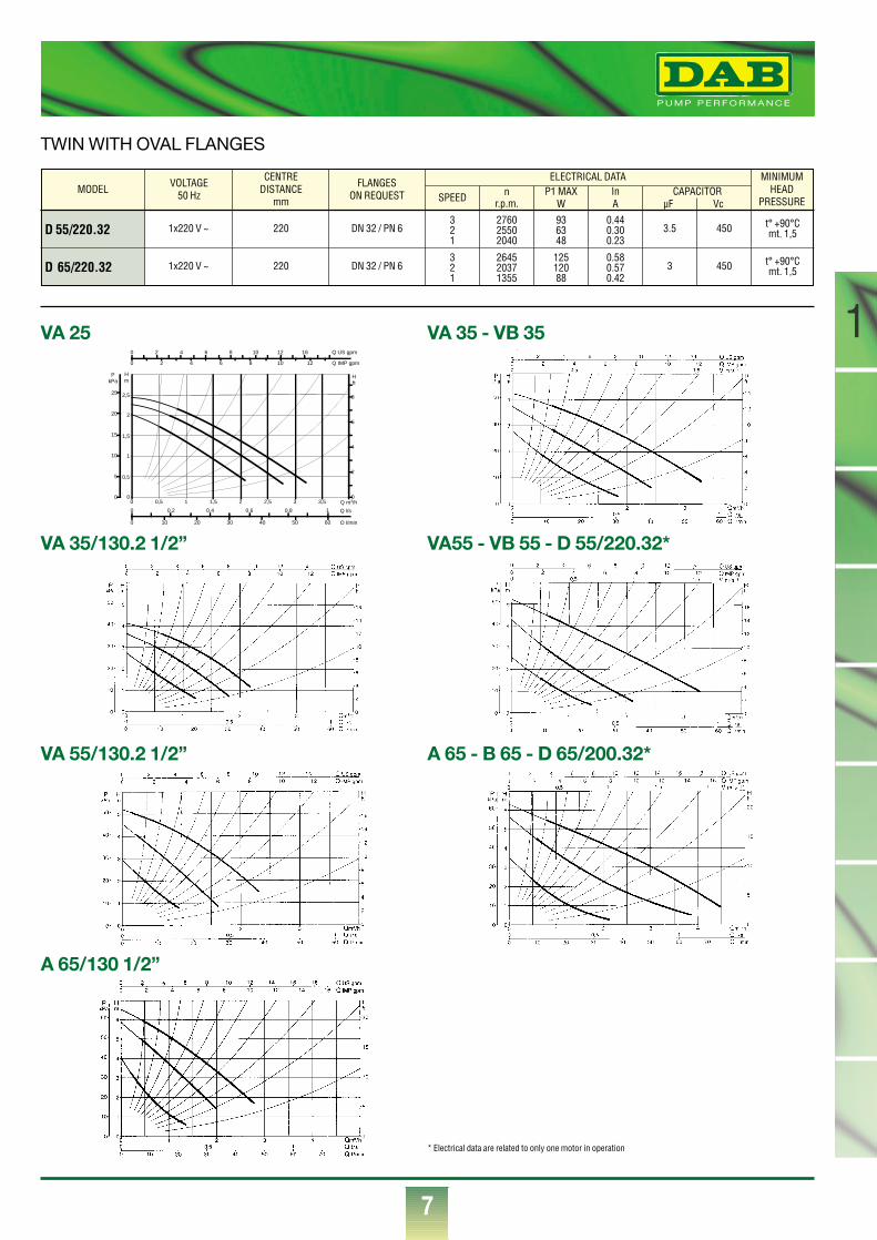
TWIN WITH OVAL FLANGES
MODEL
D 55/220.32
D 65/220.32
VOLTAGE50 Hz
1x220 V ~
1x220 V ~
220
220
DN 32 / PN 6
DN 32 / PN 6
321
321
276025502040
264520371355
936348
12512088
0.440.300.23
0.580.570.42
t° +90°Cmt. 1,5
t° +90°Cmt. 1,5
3.5
3
450
450
CENTREDISTANCE
mm
MINIMUMHEAD
PRESSURE
FLANGES ON REQUEST
ELECTRICAL DATA
SPEED nr.p.m.
P1 MAXW
InA
CAPACITORµF Vc
0 0,5 1 1,5 2 2,5 3 3,5 Q m3/h0
0,5
1
1,5
2
2,5
Hm
0
5
10
15
20
25
PkPa
0 10 20 30 40 50 60 Q l/min
0 0,2 0,4 0,6 0,8 1 Q l/s
0
2
4
6
8
H ft
0 2 4 6 8 10 12 16 Q US gpm
0 2 4 6 8 10 12 Q IMP gpm
VA 25
VA 35/130.2 1/2”
VA 55/130.2 1/2”
A 65/130 1/2”
VA 35 - VB 35
VA55 - VB 55 - D 55/220.32*
A 65 - B 65 - D 65/200.32*
* Electrical data are related to only one motor in operation
®
8
1
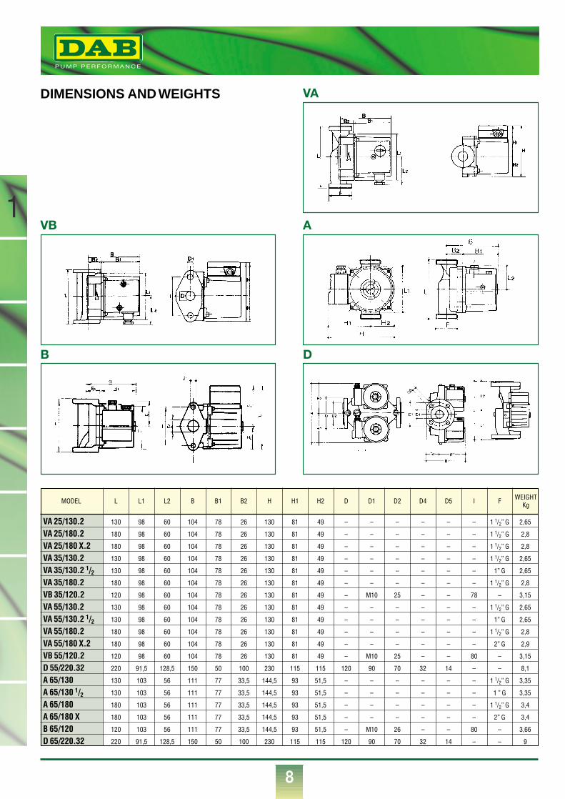
VA 25/130.2 130 98 60 104 78 26 130 81 49 – – – – – – 1 1/2” G 2,65
VA 25/180.2 180 98 60 104 78 26 130 81 49 – – – – – – 1 1/2” G 2,8
VA 25/180 X.2 180 98 60 104 78 26 130 81 49 – – – – – – 1 1/2” G 2,8
VA 35/130.2 130 98 60 104 78 26 130 81 49 – – – – – – 1 1/2” G 2,65
VA 35/130.2 1/2 130 98 60 104 78 26 130 81 49 – – – – – – 1” G 2,65
VA 35/180.2 180 98 60 104 78 26 130 81 49 – – – – – – 1 1/2” G 2,8
VB 35/120.2 120 98 60 104 78 26 130 81 49 – M10 25 – – 78 – 3,15
VA 55/130.2 130 98 60 104 78 26 130 81 49 – – – – – – 1 1/2” G 2,65
VA 55/130.2 1/2 130 98 60 104 78 26 130 81 49 – – – – – – 1” G 2,65
VA 55/180.2 180 98 60 104 78 26 130 81 49 – – – – – – 1 1/2” G 2,8
VA 55/180 X.2 180 98 60 104 78 26 130 81 49 – – – – – – 2” G 2,9
VB 55/120.2 120 98 60 104 78 26 130 81 49 – M10 25 – – 80 – 3,15
D 55/220.32 220 91,5 128,5 150 50 100 230 115 115 120 90 70 32 14 – – 8,1
A 65/130 130 103 56 111 77 33,5 144,5 93 51,5 – – – – – – 1 1/2” G 3,35
A 65/130 1/2 130 103 56 111 77 33,5 144,5 93 51,5 – – – – – – 1 ” G 3,35
A 65/180 180 103 56 111 77 33,5 144,5 93 51,5 – – – – – – 1 1/2” G 3,4
A 65/180 X 180 103 56 111 77 33,5 144,5 93 51,5 – – – – – – 2” G 3,4
B 65/120 120 103 56 111 77 33,5 144,5 93 51,5 – M10 26 – – 80 – 3,66
D 65/220.32 220 91,5 128,5 150 50 100 230 115 115 120 90 70 32 14 – – 9
MODEL L L1 L2 B B1 B2 H H1 H2 D D1 D2 D4 D5 I F WEIGHTKg
DIMENSIONS AND WEIGHTS VA
D
A
B
VB
1
9
ELECTRICAL AND HYDRAULIC DATA
DIMENSIONS AND WEIGHTS
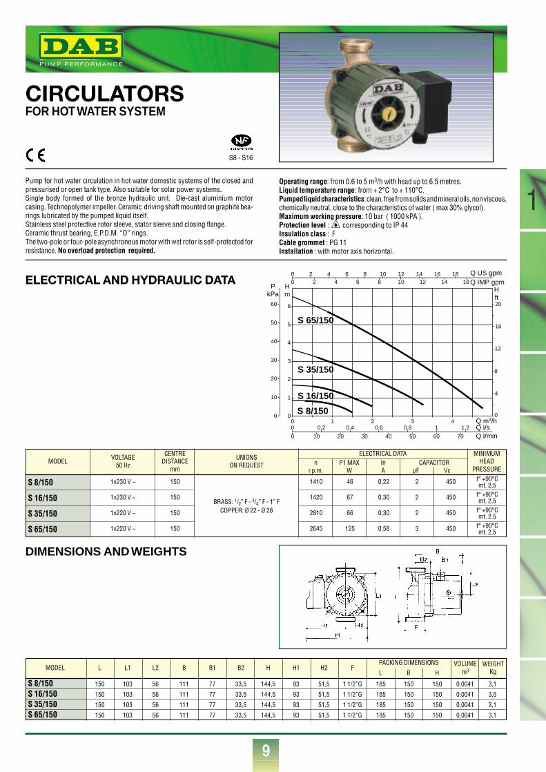
CIRCULATORSFOR HOT WATER SYSTEM
Pump for hot water circulation in hot water domestic systems of the closed andpressurised or open tank type. Also suitable for solar power systems.Single body formed of the bronze hydraulic unit. Die-cast aluminium motorcasing. Technopolymer impeller. Ceramic driving shaft mounted on graphite bea-rings lubricated by the pumped liquid itself.Stainless steel protective rotor sleeve, stator sleeve and closing flange.Ceramic thrust bearing, E.P.D.M. “O” rings.The two-pole or four-pole asynchronous motor with wet rotor is self-protected forresistance. No overload protection required.
Operating range: from 0.6 to 5 m3/h with head up to 6.5 metres.Liquid temperature range: from + 2°C to + 110°C.Pumped liquid characteristics: clean, free from solids and mineral oils, non viscous,chemically neutral, close to the characteristics of water ( max 30% glycol).Maximum working pressure: 10 bar ( 1000 kPA ).Protection level : corresponding to IP 44Insulation class : FCable grommet : PG 11Installation : with motor axis horizontal.
®
MODEL
S 8/150
S 16/150
S 35/150
S 65/150
VOLTAGE50 Hz
1x230 V ~
1x230 V ~
1x220 V ~
1x220 V ~
150
150
150
150
t° +90°Cmt. 2,5
t° +90°Cmt. 2,5
t° +90°Cmt. 2,5
t° +90°Cmt. 2,5
BRASS: 1/2” F - 3/4” F - 1” FCOPPER: Ø 22 - Ø 28
2
2
2
3
1410
1420
2810
2645
46
67
66
125
0,22
0,30
0,30
0,58
450
450
450
450
CENTREDISTANCE
mm
MINIMUMHEAD
PRESSURE
UNIONSON REQUEST
ELECTRICAL DATAn
r.p.m.P1 MAX
WInA
CAPACITORµF Vc
S 8/150 150 103 56 111 77 33,5 144,5 93 51,5 1 1/2”G 185 150 150 0,0041 3,1
S 16/150 150 103 56 111 77 33,5 144,5 93 51,5 1 1/2”G 185 150 150 0,0041 3,5
S 35/150 150 103 56 111 77 33,5 144,5 93 51,5 1 1/2”G 185 150 150 0,0041 3,1
S 65/150 150 103 56 111 77 33,5 144,5 93 51,5 1 1/2”G 185 150 150 0,0041 3,1
MODEL L L1 L2 B B1 B2 H H1 H2 FPACKING DIMENSIONS VOLUME
m3WEIGHT
KgL B H
Q m3/h0 1 2 3 40
1
2
3
4
5
6
0
4
8
12
16
20
0
00
Q l/sQ l/min
Q IMP gpmQ US gpm
0
0
0,2 0,4 0,6 0,8 1 1,2
10 20 30 40 50 60 70
Hm
Hft
PkPa
10
20
30
40
50
60
2 4 6 8 10 12 14 16 182 4 6 8 10 12 14 16
S 16/150
S 35/150
S 65/150
S 8/150
S8 - S16
®
10
1
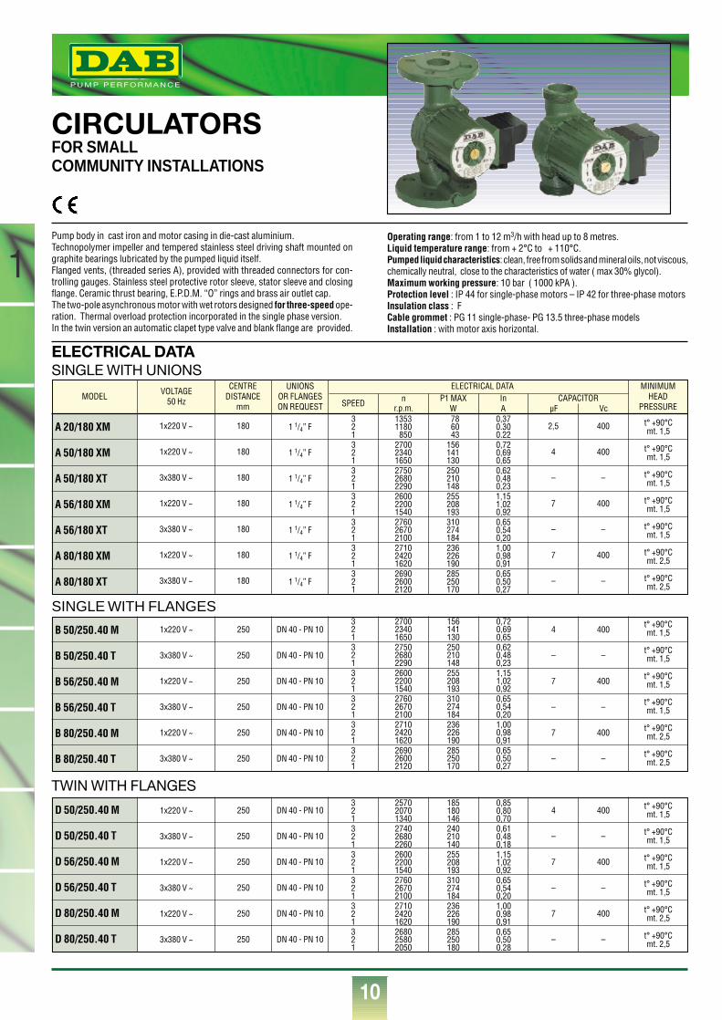
CIRCULATORSFOR SMALLCOMMUNITY INSTALLATIONS
Pump body in cast iron and motor casing in die-cast aluminium.Technopolymer impeller and tempered stainless steel driving shaft mounted ongraphite bearings lubricated by the pumped liquid itself.Flanged vents, (threaded series A), provided with threaded connectors for con-trolling gauges. Stainless steel protective rotor sleeve, stator sleeve and closingflange. Ceramic thrust bearing, E.P.D.M. “O” rings and brass air outlet cap.The two-pole asynchronous motor with wet rotors designed for three-speed ope-ration. Thermal overload protection incorporated in the single phase version.In the twin version an automatic clapet type valve and blank flange are provided.
Operating range: from 1 to 12 m3/h with head up to 8 metres.Liquid temperature range: from + 2°C to + 110°C.Pumped liquid characteristics: clean, free from solids and mineral oils, not viscous,chemically neutral, close to the characteristics of water ( max 30% glycol).Maximum working pressure: 10 bar ( 1000 kPA ).Protection level : IP 44 for single-phase motors – IP 42 for three-phase motorsInsulation class : FCable grommet : PG 11 single-phase- PG 13.5 three-phase modelsInstallation : with motor axis horizontal.
MODEL
A 20/180 XM
A 50/180 XM
A 50/180 XT
A 56/180 XM
A 56/180 XT
A 80/180 XM
A 80/180 XT
VOLTAGE50 Hz
1x220 V ~
1x220 V ~
3x380 V ~
1x220 V ~
3x380 V ~
1x220 V ~
3x380 V ~
180
180
180
180
180
180
180
1 1/4” F
1 1/4” F
1 1/4” F
1 1/4” F
1 1/4” F
1 1/4” F
1 1/4” F
321321321321321321321
13531180850
270023401650275026802290260022001540276026702100271024201620269026002120
786043
156141130250210148255208193310274184236226190285250170
0,370.300.220,720,690,650,620,480,231,151,020,920,650,540,201,000,980,910,650,500,27
t° +90°Cmt. 1,5
t° +90°Cmt. 1,5
t° +90°Cmt. 1,5
t° +90°Cmt. 1,5
t° +90°Cmt. 1,5
t° +90°Cmt. 2,5
t° +90°Cmt. 2,5
2,5
4
–
7
–
7
–
400
400
–
400
–
400
–
CENTREDISTANCE
mm
MINIMUMHEAD
PRESSURE
UNIONSOR FLANGESON REQUEST
ELECTRICAL DATA
SPEED nr.p.m.
P1 MAXW
InA
CAPACITORµF Vc
B 50/250.40 M
B 50/250.40 T
B 56/250.40 M
B 56/250.40 T
B 80/250.40 M
B 80/250.40 T
1x220 V ~
3x380 V ~
1x220 V ~
3x380 V ~
1x220 V ~
3x380 V ~
250
250
250
250
250
250
DN 40 - PN 10
DN 40 - PN 10
DN 40 - PN 10
DN 40 - PN 10
DN 40 - PN 10
DN 40 - PN 10
321321321321321321
270023401650275026802290260022001540276026702100271024201620269026002120
156141130250210148255208193310274184236226190285250170
0,720,690,650,620,480,231,151,020,920,650,540,201,000,980,910,650,500,27
t° +90°Cmt. 1,5
t° +90°Cmt. 1,5
t° +90°Cmt. 1,5
t° +90°Cmt. 1,5
t° +90°Cmt. 2,5
t° +90°Cmt. 2,5
4
–
7
–
7
–
400
–
400
–
400
–
ELECTRICAL DATASINGLE WITH UNIONS
SINGLE WITH FLANGES
TWIN WITH FLANGES
D 50/250.40 M
D 50/250.40 T
D 56/250.40 M
D 56/250.40 T
D 80/250.40 M
D 80/250.40 T
1x220 V ~
3x380 V ~
1x220 V ~
3x380 V ~
1x220 V ~
3x380 V ~
250
250
250
250
250
250
DN 40 - PN 10
DN 40 - PN 10
DN 40 - PN 10
DN 40 - PN 10
DN 40 - PN 10
DN 40 - PN 10
321321321321321321
257020701340274026802260260022001540276026702100271024201620268025802050
185180146240210140255208193310274184236226190285250180
0,850,800,700,610,480,181,151,020,920,650,540,201,000,980,910,650,500.28
t° +90°Cmt. 1,5
t° +90°Cmt. 1,5
t° +90°Cmt. 1,5
t° +90°Cmt. 1,5
t° +90°Cmt. 2,5
t° +90°Cmt. 2,5
4
–
7
–
7
–
400
–
400
–
400
–
®
11
1
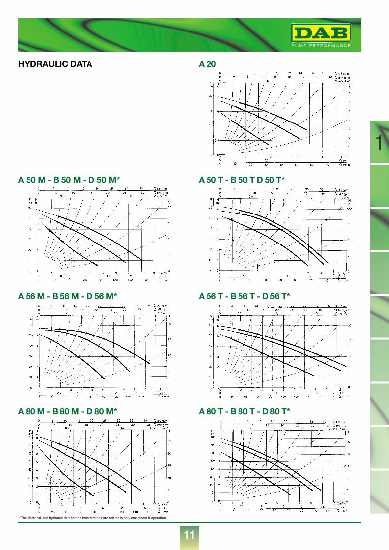
A 50 M - B 50 M - D 50 M* A 50 T - B 50 T D 50 T*
A 56 M - B 56 M - D 56 M* A 56 T - B 56 T - D 56 T*
A 80 M - B 80 M - D 80 M* A 80 T - B 80 T - D 80 T*
HYDRAULIC DATA A 20
* The electrical and hydraulic data for the twin versions are related to only one motor in operation.
®
12
1
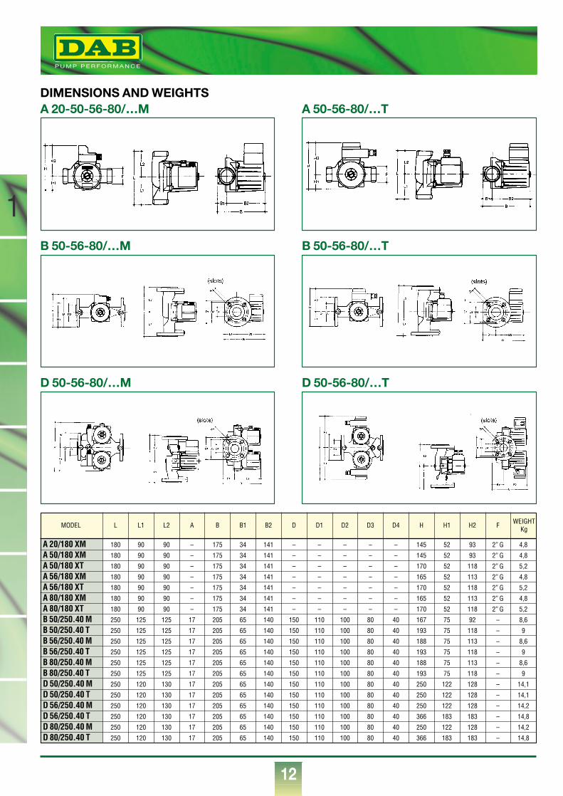
A 20/180 XM 180 90 90 – 175 34 141 – – – – – 145 52 93 2” G 4,8
A 50/180 XM 180 90 90 – 175 34 141 – – – – – 145 52 93 2” G 4,8
A 50/180 XT 180 90 90 – 175 34 141 – – – – – 170 52 118 2” G 5,2
A 56/180 XM 180 90 90 – 175 34 141 – – – – – 165 52 113 2” G 4,8
A 56/180 XT 180 90 90 – 175 34 141 – – – – – 170 52 118 2” G 5,2
A 80/180 XM 180 90 90 – 175 34 141 – – – – – 165 52 113 2” G 4,8
A 80/180 XT 180 90 90 – 175 34 141 – – – – – 170 52 118 2” G 5,2
B 50/250.40 M 250 125 125 17 205 65 140 150 110 100 80 40 167 75 92 – 8,6
B 50/250.40 T 250 125 125 17 205 65 140 150 110 100 80 40 193 75 118 – 9
B 56/250.40 M 250 125 125 17 205 65 140 150 110 100 80 40 188 75 113 – 8,6
B 56/250.40 T 250 125 125 17 205 65 140 150 110 100 80 40 193 75 118 – 9
B 80/250.40 M 250 125 125 17 205 65 140 150 110 100 80 40 188 75 113 – 8,6
B 80/250.40 T 250 125 125 17 205 65 140 150 110 100 80 40 193 75 118 – 9
D 50/250.40 M 250 120 130 17 205 65 140 150 110 100 80 40 250 122 128 – 14,1
D 50/250.40 T 250 120 130 17 205 65 140 150 110 100 80 40 250 122 128 – 14,1
D 56/250.40 M 250 120 130 17 205 65 140 150 110 100 80 40 250 122 128 – 14,2
D 56/250.40 T 250 120 130 17 205 65 140 150 110 100 80 40 366 183 183 – 14,8
D 80/250.40 M 250 120 130 17 205 65 140 150 110 100 80 40 250 122 128 – 14,2
D 80/250.40 T 250 120 130 17 205 65 140 150 110 100 80 40 366 183 183 – 14,8
MODEL L L1 L2 A B B1 B2 D D1 D2 D3 D4 H H1 H2 F WEIGHTKg
DIMENSIONS AND WEIGHTSA 50-56-80/…TA 20-50-56-80/…M
B 50-56-80/…TB 50-56-80/…M
D 50-56-80/…TD 50-56-80/…M
®
13
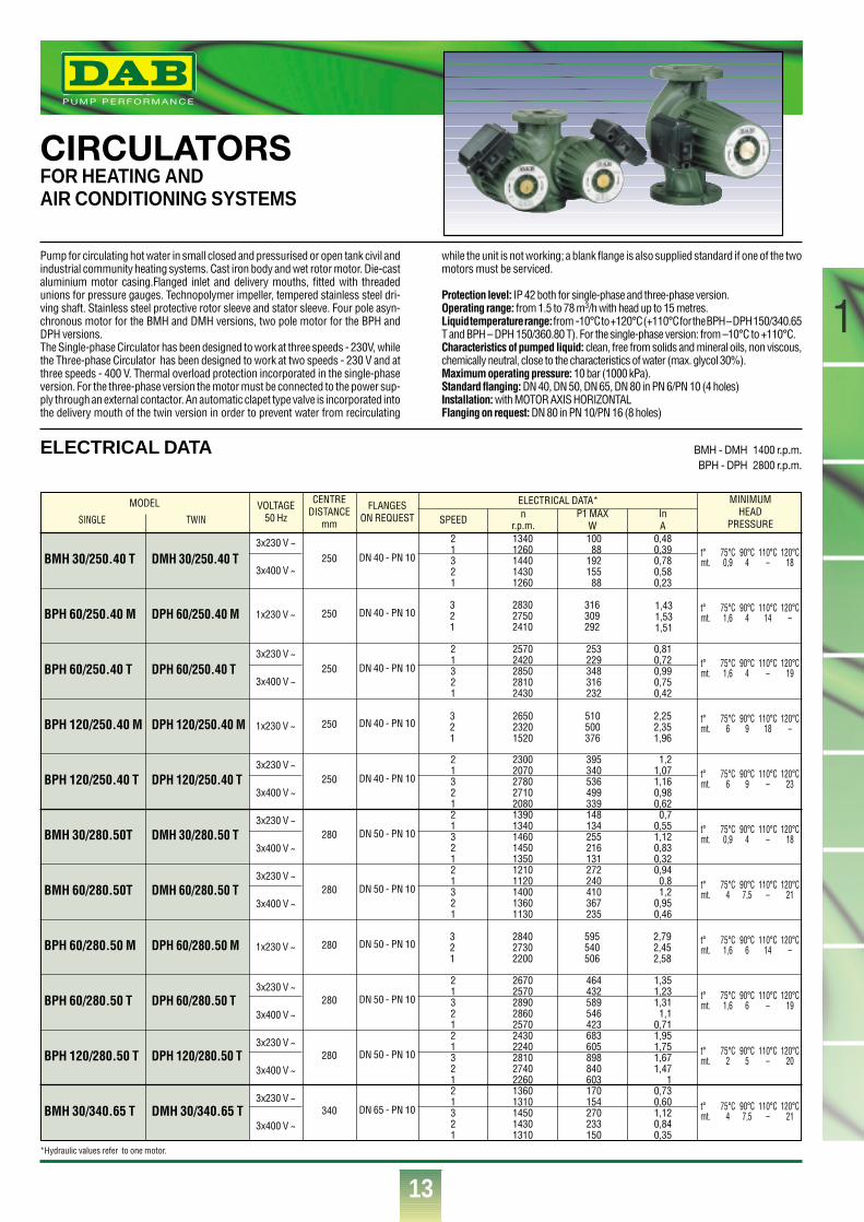
CIRCULATORSFOR HEATING AND AIR CONDITIONING SYSTEMS
Pump for circulating hot water in small closed and pressurised or open tank civil andindustrial community heating systems. Cast iron body and wet rotor motor. Die-castaluminium motor casing.Flanged inlet and delivery mouths, fitted with threadedunions for pressure gauges. Technopolymer impeller, tempered stainless steel dri-ving shaft. Stainless steel protective rotor sleeve and stator sleeve. Four pole asyn-chronous motor for the BMH and DMH versions, two pole motor for the BPH andDPH versions. The Single-phase Circulator has been designed to work at three speeds - 230V, whilethe Three-phase Circulator has been designed to work at two speeds - 230 V and atthree speeds - 400 V. Thermal overload protection incorporated in the single-phaseversion. For the three-phase version the motor must be connected to the power sup-ply through an external contactor. An automatic clapet type valve is incorporated intothe delivery mouth of the twin version in order to prevent water from recirculating
while the unit is not working; a blank flange is also supplied standard if one of the twomotors must be serviced.
Protection level: IP 42 both for single-phase and three-phase version.Operating range: from 1.5 to 78 m3/h with head up to 15 metres.Liquid temperature range:from -10°C to +120°C (+110°C for the BPH – DPH 150/340.65T and BPH – DPH 150/360.80 T). For the single-phase version: from –10°C to +110°C.Characteristics of pumped liquid: clean, free from solids and mineral oils, non viscous,chemically neutral, close to the characteristics of water (max. glycol 30%).Maximum operating pressure: 10 bar (1000 kPa).Standard flanging: DN 40, DN 50, DN 65, DN 80 in PN 6/PN 10 (4 holes)Installation: with MOTOR AXIS HORIZONTALFlanging on request: DN 80 in PN 10/PN 16 (8 holes)
t° 75°C 90°C 110°C 120°Cmt. 0,9 4 – 18
t° 75°C 90°C 110°C 120°Cmt. 1,6 4 14 –
t° 75°C 90°C 110°C 120°Cmt. 1,6 4 – 19
t° 75°C 90°C 110°C 120°Cmt. 6 9 18 –
t° 75°C 90°C 110°C 120°Cmt. 6 9 – 23
t° 75°C 90°C 110°C 120°Cmt. 0,9 4 – 18
t° 75°C 90°C 110°C 120°Cmt. 4 7,5 – 21
t° 75°C 90°C 110°C 120°Cmt. 1,6 6 14 –
t° 75°C 90°C 110°C 120°Cmt. 1,6 6 – 19
t° 75°C 90°C 110°C 120°Cmt. 2 5 – 20
t° 75°C 90°C 110°C 120°Cmt. 4 7,5 – 21
MINIMUMHEAD
PRESSURE
ELECTRICAL DATA*MODEL
ELECTRICAL DATA BMH - DMH 1400 r.p.m.BPH - DPH 2800 r.p.m.
1
VOLTAGE50 Hz
3x230 V ~
3x400 V ~
3x230 V ~
3x400 V ~
3x230 V ~
3x400 V ~
3x230 V ~
3x400 V ~
3x230 V ~
3x400 V ~
3x230 V ~
3x400 V ~
3x230 V ~
3x400 V ~
3x230 V ~
3x400 V ~
CENTREDISTANCE
mm
250
250
250
250
250
280
280
280
280
280
340
FLANGESON REQUEST
DN 40 - PN 10
DN 40 - PN 10
DN 40 - PN 10
DN 40 - PN 10
DN 40 - PN 10
DN 50 - PN 10
DN 50 - PN 10
DN 50 - PN 10
DN 50 - PN 10
DN 50 - PN 10
DN 65 - PN 10
SPEEDSINGLE TWIN
21321
21321
213212132121321
213212132121321
nr.p.m.13401260144014301260
25702420285028102430
230020702780271020801390134014601450135012101120140013601130
267025702890286025702430224028102740226013601310145014301310
P1 MAXW10088
19215588
253229348316232
395340536499339148134255216131272240410367235
464432589546423683605898840603170154270233150
InA
0,480,390,780,580,23
0,810,720,990,750,42
1,21,071,160,980,620,7
0,551,120,830,320,940,81,2
0,950,46
1,351,231,311,1
0,711,951,751,671,47
10,730,601,120,840,35
BMH 30/250.40 T
BPH 60/250.40 M
BPH 60/250.40 T
BPH 120/250.40 M
BPH 120/250.40 T
BMH 30/280.50T
BMH 60/280.50T
BPH 60/280.50 M
BPH 60/280.50 T
BPH 120/280.50 T
BMH 30/340.65 T
DMH 30/250.40 T
DPH 60/250.40 M
DPH 60/250.40 T
DPH 120/250.40 M
DPH 120/250.40 T
DMH 30/280.50 T
DMH 60/280.50 T
DPH 60/280.50 M
DPH 60/280.50 T
DPH 120/280.50 T
DMH 30/340.65 T
1x230 V ~321
283027502410
316309292
1x230 V ~321
265023201520
510500376
2,252,351,96
1x230 V ~321
284027302200
595540506
2,792,452,58
1,431,531,51
*Hydraulic values refer to one motor.
®
14
1t° 75°C 90°C 110°C 120°Cmt. 4 7,5 – 21
t° 75°C 90°C 110°C 120°Cmt. 1 4 13 –
t° 75°C 90°C 110°C 120°Cmt. 1 4 – 18
t° 75°C 90°C 110°C 120°Cmt. 6 9 – 22
t° 75°C 90°C 110°C 120°Cmt. 7 11 18 –
t° 75°C 90°C 110°C 120°Cmt. 4 7,5 – 21
t° 75°C 90°C 110°C 120°Cmt. 2 5 – 20
t° 75°C 90°C 110°C 120°Cmt. 6 10 – 22
t° 75°C 90°C 110°C 120°Cmt. 7 11 18 –
MINIMUMHEAD
PRESSURE
ELECTRICAL DATA*MODEL VOLTAGE50 Hz
3x230 V ~
3x400 V ~
3x230 V ~
3x400 V ~
3x230 V ~
3x400 V ~
3x230 V ~
3x400 V ~
3x230 V ~
3x400 V ~
3x230 V ~
3x400 V ~
3x230 V ~
3x400 V ~
3x230 V ~
3x400 V ~
CENTREDISTANCE
mm
340
340
340
340
340
360
360
360
360
FLANGESON REQUEST
DN 65 - PN 10
DN 65 - PN 10
DN 65 - PN 10
DN 65 - PN 10
DN 65 - PN 10
DN 80 - PN 10
DN 80 - PN 10
DN 80 - PN 10
DN 80 - PN 10
SPEED
2
1
3
2
1
2
1
3
2
1
2
1
3
2
1
2
1
3
2
1
2
1
3
2
1
2
1
3
2
1
2
1
3
2
1
2
1
3
2
1
nr.p.m.
1170
1070
1380
1350
1090
2550
2380
2850
2800
2400
2630
2500
2880
2830
2520
2410
2250
2800
2730
2250
1110
1010
1370
1330
1030
1180
1100
1390
1350
1100
2500
2340
2830
2780
2350
2140
1900
2710
2610
1940
P1 MAXW
295
257
445
403
255
582
532
756
705
535
1001
940
1275
1200
934
1345
1188
1796
1690
1210
313
268
484
437
266
535
465
763
663
465
1410
1292
1820
1710
1302
1984
1695
2870
2686
1710
InA
1
0,85
1,2
0,97
0,49
1,67
1,53
1,5
1,3
0,9
2,85
2,66
2,64
2,25
1,52
3,8
3,36
3,25
2,93
2
1,05
0,88
1,23
1
0,51
1,82
1,55
2,04
1,65
0,89
3,95
3,6
3,3
2,93
2,13
5,62
4,82
4,64
4,32
2,85
BMH 60/340.65 T
BPH 60/340.65 M
BPH 60/340.65 T
BPH 120/340.65 T
BPH 150/340.65 T
BMH 30/360.80 T
BMH 60/360.80 T
BPH 120/360.80 T
BPH 150/360.80 T
DMH 60/340.65 T
DPH 60/340.65 M
DPH 60/340.65 T
DPH 120/340.65 T
DPH 150/340.65 T
DMH 30/360.80 T
DMH 60/360.80 T
DPH 120/360.80 T
DPH 150/360.80 T
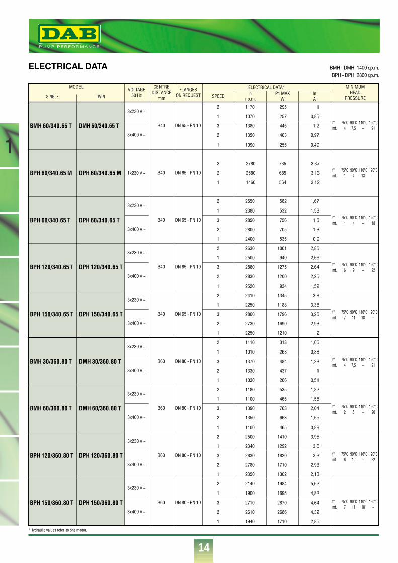
ELECTRICAL DATA BMH - DMH 1400 r.p.m.BPH - DPH 2800 r.p.m.
1x230 V ~
3
2
1
2780
2580
1460
735
685
564
3,37
3,13
3,12
SINGLE TWIN
*Hydraulic values refer to one motor.
®
15
1
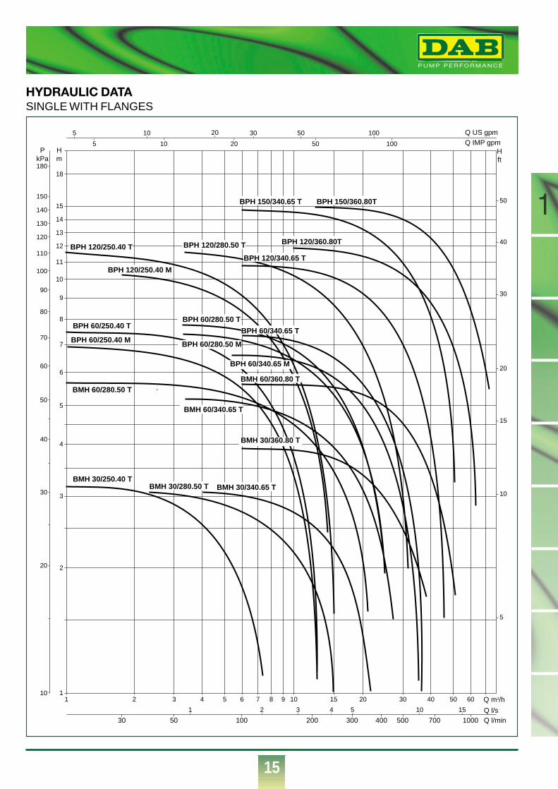
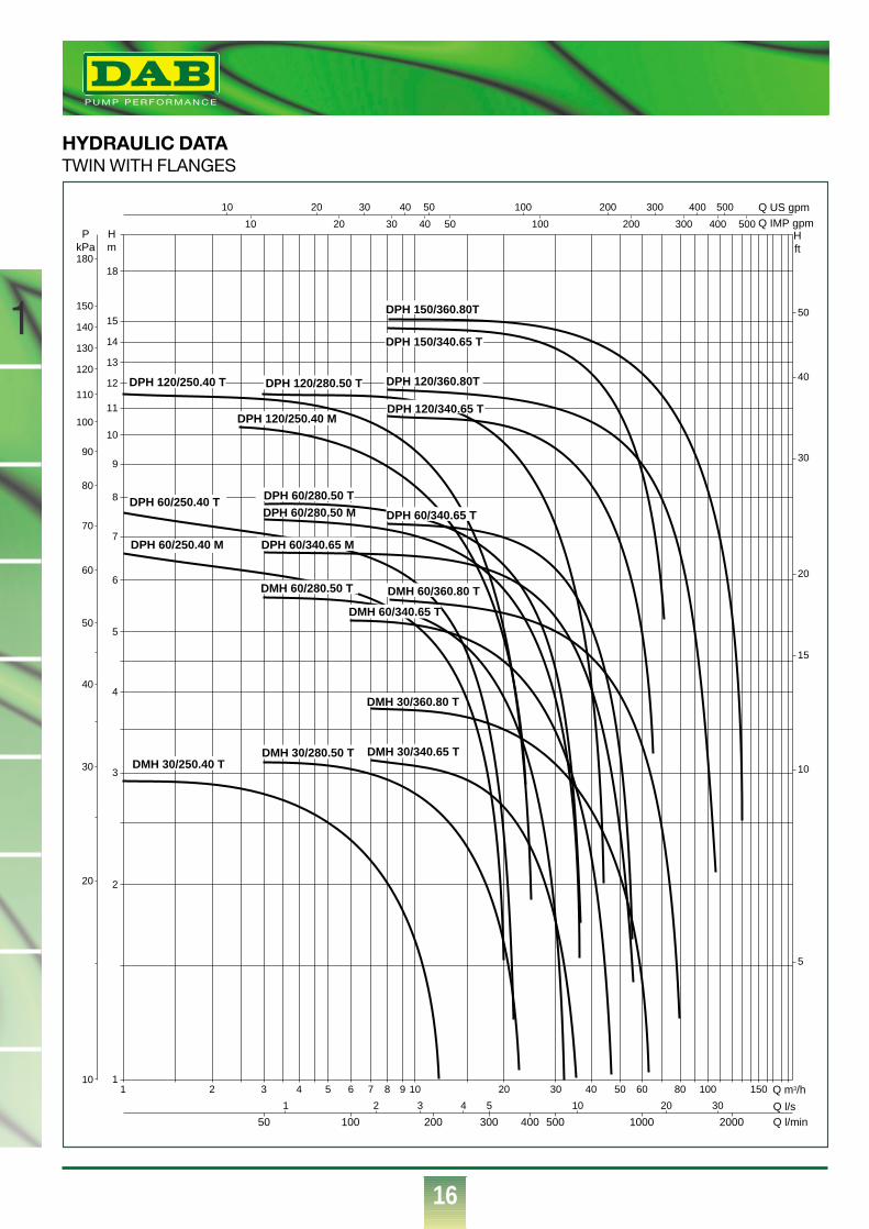
HYDRAULIC DATASINGLE WITH FLANGES
1 2 3 4 5 6 7 8 9 10 15 20 30 40 50 60 Q m3/h
Q l/sQ l/min500
1 2 3 4 5 10 15
700 10002001005030 300 400
1
18
15
14
13
12
11
10
9
8
7
6
5
4
3
2
Q IMP gpmQ US gpm
Hm
Hft
PkPa
5
5
10
180
150
140
130
120
110
100
90
80
70
60
50
40
30
20
5
10
10 20 50 100
10 30 50 100
15
20
30
40
50
20
BMH 30/250.40 T
BMH 60/280.50 T
BPH 60/250.40 M
BPH 60/250.40 T
BPH 120/250.40 T
BPH 120/250.40 M
BPH 120/280.50 T
BPH 60/280.50 T
BPH 60/280.50 M
BPH 60/340.65 T
BPH 60/340.65 M
BMH 60/360.80 T
BMH 60/340.65 T
BMH 30/280.50 T BMH 30/340.65 T
BMH 30/360.80 T
BPH 150/340.65 T BPH 150/360.80T
BPH 120/360.80T
BPH 120/340.65 T
®
16
1
HYDRAULIC DATATWIN WITH FLANGES
1 1501008060504030201098765432 Q m3/h
Q l/sQ l/min
1 2 3 4 5 10 20 30
50 100 200 300 400 500 1000 2000
1
18
15
14
13
12
11
10
9
8
7
6
5
4
3
2
Q IMP gpmQ US gpm
Hm
Hft
PkPa
10
180
150
140
130
120
110
100
90
80
70
60
50
40
30
20
5
10
10 20 30 40 50 100 200 300 400 500
10 20 30 40 50 100 200 300 400 500
15
20
30
40
50
DPH 120/250.40 T DPH 120/280.50 T
DPH 60/280.50 T
DMH 30/280.50 T DMH 30/340.65 T
DMH 30/360.80 T
DPH 150/340.65 T
DPH 150/360.80T
DMH 30/250.40 T
DPH 60/250.40 M
DPH 60/250.40 T
DMH 60/280.50 T
DPH 60/280.50 M
DMH 60/340.65 T
DPH 60/340.65 M
DPH 60/340.65 T
DPH 120/340.65 T
DMH 60/360.80 T
DPH 120/360.80T
DPH 120/250.40 M
®
17
1
250
250
250
250
250
280
280
280
280
280
340
340
340
340
340
340
360
360
360
360
125
125
125
125
125
140
140
140
140
140
170
170
170
170
170
170
170
170
170
170
125
125
125
125
125
140
140
140
140
140
170
170
170
170
170
170
190
190
190
190
66
66
66
66
66
73
73
73
73
73
82
82
82
82
82
82
97
97
97
97
200
200
200
200
200
236
236
236
236
236
249
249
249
249
299
299
254
304
304
304
150
150
150
150
150
165
165
165
165
165
185
185
185
185
185
185
200
200
200
200
110
110
110
110
110
125
125
125
125
125
145
145
145
145
145
145
160
160
160
160
100
100
100
100
100
110
110
110
110
110
130
130
130
130
130
130
150
150
150
150
80
80
80
80
80
90
90
90
90
90
110
110
110
110
110
110
130
130
130
130
40
40
40
40
40
50
50
50
50
50
65
65
65
65
65
65
80
80
80
80
100
100
100
100
100
100
100
100
100
100
100
100
100
100
100
100
115
115
115
115
M10
M10
M10
M10
M10
M10
M10
M10
M10
M10
M12
M12
M12
M12
M12
M12
M12
M12
M12
M12
221
221
221
221
221
252
252
252
252
252
257
257
257
257
257
257
257
257
257
257
83
83
83
83
83
96
96
96
96
96
100
100
100
100
100
100
100
100
100
100
138
138
138
138
138
156
156
156
156
156
157
157
157
157
157
157
157
157
157
157
20
20
20
20
20
27,5
27,5
27,5
27,5
29,5
31
31
31
34
36,5
36,5
34,5
44
44
44
266
266
266
266
266
309
309
309
309
309
331
331
331
331
381
381
351
401
401
401
18
18
18
18
18
18
18
18
18
18
18
18
18
18
18
18
18
18
18
18
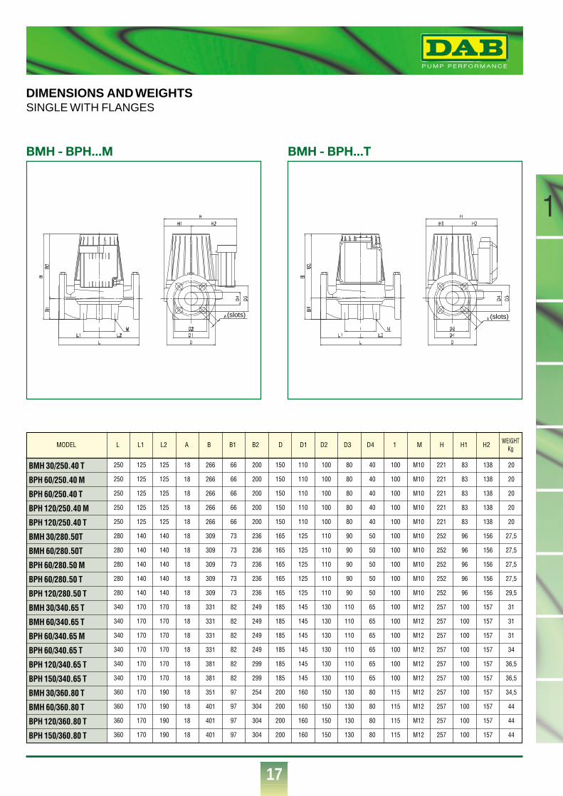
BMH 30/250.40 T
BPH 60/250.40 M
BPH 60/250.40 T
BPH 120/250.40 M
BPH 120/250.40 T
BMH 30/280.50T
BMH 60/280.50T
BPH 60/280.50 M
BPH 60/280.50 T
BPH 120/280.50 T
BMH 30/340.65 T
BMH 60/340.65 T
BPH 60/340.65 M
BPH 60/340.65 T
BPH 120/340.65 T
BPH 150/340.65 T
BMH 30/360.80 T
BMH 60/360.80 T
BPH 120/360.80 T
BPH 150/360.80 T
L L1 L2 A B B1 B2 D D1 D2 D3 D4 1 M H H1 H2MODEL WEIGHTKg
DIMENSIONS AND WEIGHTSSINGLE WITH FLANGES
(slots)
BMH - BPH...M
(slots)
BMH - BPH...T
®
18
1
250
250
250
250
250
280
280
280
280
280
340
340
340
340
340
340
360
360
360
360
105
105
105
105
105
130
130
130
130
130
138,5
138,5
138,5
138,5
138,5
138,5
160
160
160
160
145
145
145
145
145
150
150
150
150
150
201,5
201,5
201,5
201,5
201,5
201,5
200
200
200
200
66
66
66
66
66
73
73
73
73
73
82
82
82
82
82
82
97
97
97
97
205
205
205
205
205
232
232
232
232
232
246
246
246
246
296
296
245
295
295
295
150
150
150
150
150
165
165
165
165
165
185
185
185
185
185
185
200
200
200
200
110
110
110
110
110
125
125
125
125
125
145
145
145
145
145
145
160
160
160
160
100
100
100
100
100
110
110
110
110
110
130
130
130
130
130
130
150
150
150
150
80
80
80
80
80
90
90
90
90
90
110
110
110
110
110
110
130
130
130
130
40
40
40
40
40
50
50
50
50
50
65
65
65
65
65
65
80
80
80
80
200
200
200
200
200
240
240
240
240
240
240
240
240
240
240
240
240
240
240
240
100
100
100
100
100
120
120
120
120
120
120
120
120
120
120
120
120
120
120
120
100
100
100
100
100
120
120
120
120
120
120
120
120
120
120
120
120
120
120
120
100
100
100
100
100
120
120
120
120
120
140
140
140
140
140
140
150
150
150
150
M12
M12
M12
M12
M12
M14
M14
M14
M14
M14
M14
M14
M14
M14
M14
M14
M14
M14
M14
M14
466
446
446
446
446
534
534
534
534
534
534
534
534
534
534
534
534
534
534
534
233
233
233
283
233
267
267
267
267
267
267
267
267
267
267
267
267
267
267
267
233
233
233
233
233
267
267
267
267
267
267
267
267
267
267
267
267
267
267
267
37
37
37
37
37
51,5
51,5
51,5
51,5
56
57
57
57
61,5
67
67
61,5
80
80
80
271
271
271
271
271
305
305
305
305
305
328
328
328
328
378
378
342
392
392
392
18
18
18
18
18
18
18
18
18
18
18
18
18
18
18
18
18
18
18
18
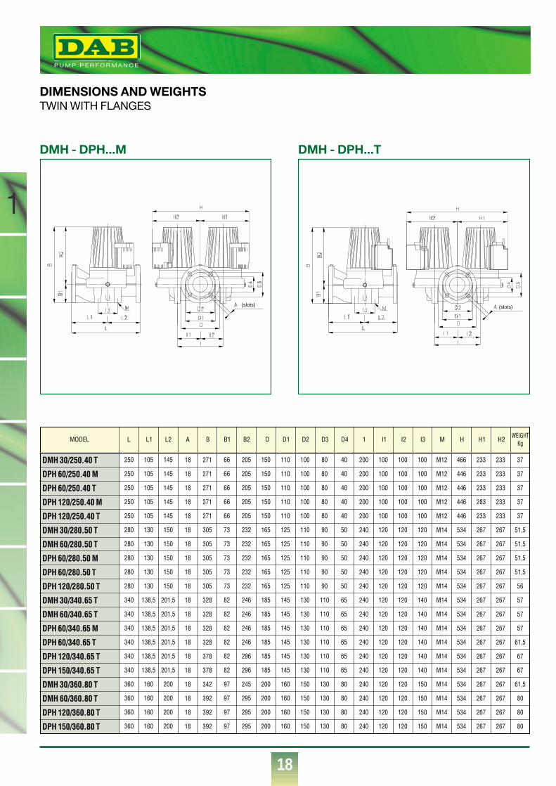
DMH 30/250.40 T
DPH 60/250.40 M
DPH 60/250.40 T
DPH 120/250.40 M
DPH 120/250.40 T
DMH 30/280.50 T
DMH 60/280.50 T
DPH 60/280.50 M
DPH 60/280.50 T
DPH 120/280.50 T
DMH 30/340.65 T
DMH 60/340.65 T
DPH 60/340.65 M
DPH 60/340.65 T
DPH 120/340.65 T
DPH 150/340.65 T
DMH 30/360.80 T
DMH 60/360.80 T
DPH 120/360.80 T
DPH 150/360.80 T
L L1 L2 A B B1 B2 D D1 D2 D3 D4 1 l1 I2 I3 M H H1 H2MODEL WEIGHTKg
DIMENSIONS AND WEIGHTSTWIN WITH FLANGES
(slots)
DMH - DPH...M
(slots)
DMH - DPH...T
®
19
1
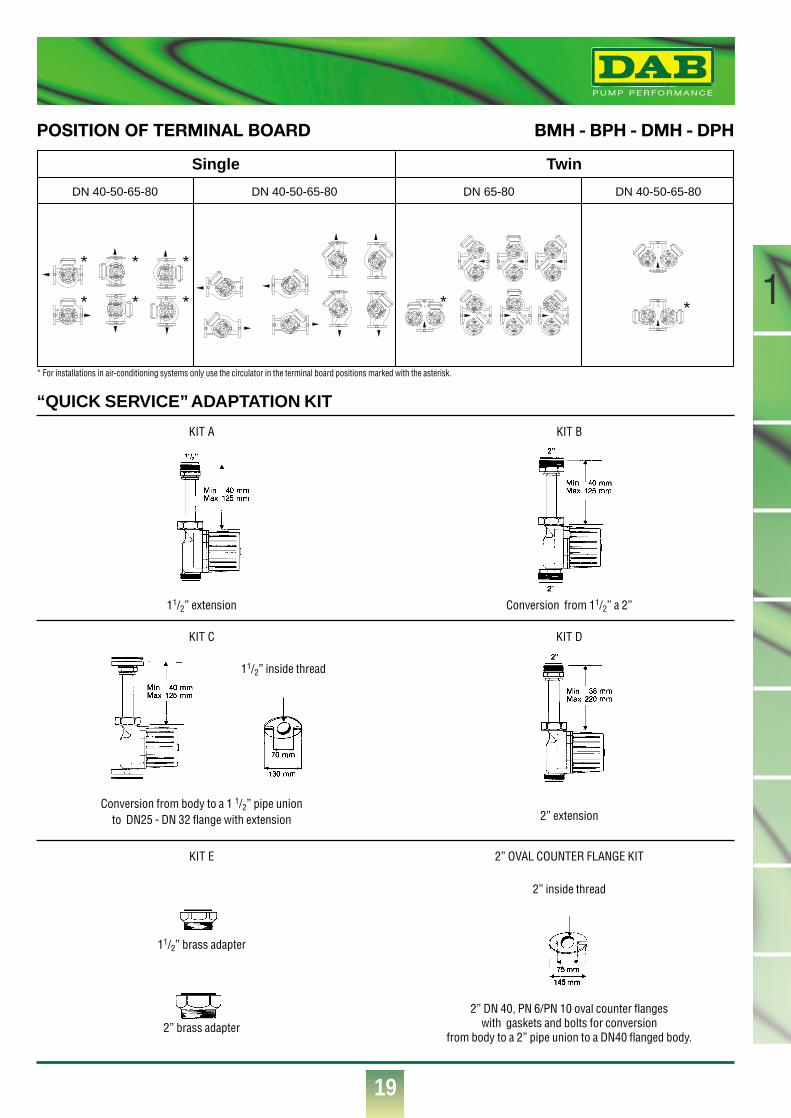
“QUICK SERVICE” ADAPTATION KIT
POSITION OF TERMINAL BOARD BMH - BPH - DMH - DPH
KIT A KIT B
KIT C
KIT E 2” OVAL COUNTER FLANGE KIT
2” DN 40, PN 6/PN 10 oval counter flanges with gaskets and bolts for conversion
from body to a 2” pipe union to a DN40 flanged body.
KIT D
11/2” extension
11/2” inside thread
Conversion from 11/2” a 2”
2” inside thread
Conversion from body to a 1 1/2” pipe union to DN25 - DN 32 flange with extension 2” extension
11/2” brass adapter
2” brass adapter
Single
DN 40-50-65-80 DN 40-50-65-80
Twin
DN 65-80 DN 40-50-65-80
*
*
*
*
*
* * *
* For installations in air-conditioning systems only use the circulator in the terminal board positions marked with the asterisk.
®
20
2
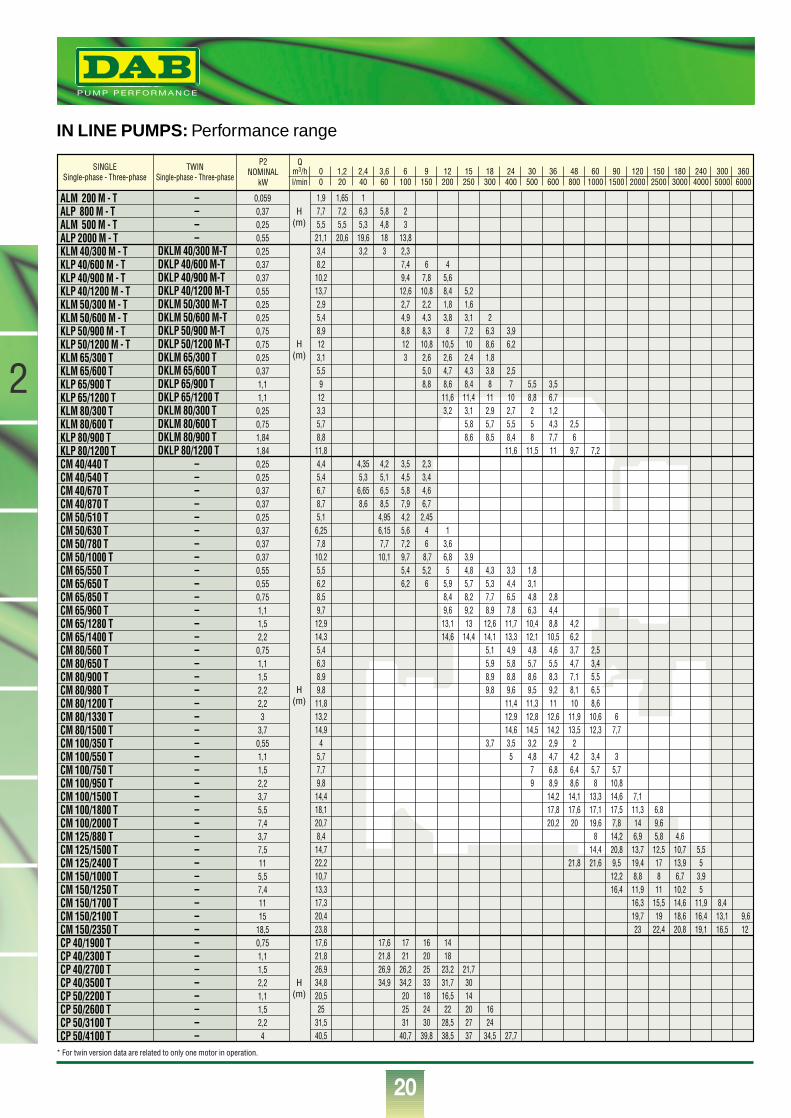
IN LINE PUMPS: Performance range
* For twin version data are related to only one motor in operation.
P2NOMINAL
kW
Qm3/h 0 1,2 2,4 3,6 6 9 12 15 18 24 30 36 48 60 90 120 150 180 240l/min 0 20 40 60 100 150 200 250 300 400 500 600 800 1000 1500 2000 2500 3000 4000
300 3605000 6000
1,9 1,65 17,7 7,2 6,3 5,8 25,5 5,5 5,3 4,8 321,1 20,6 19,6 18 13,83,4 3,2 3 2,38,2 7,4 6 410,2 9,4 7,8 5,613,7 12,6 10,8 8,4 5,22,9 2,7 2,2 1,8 1,65,4 4,9 4,3 3,8 3,1 28,9 8,8 8,3 8 7,2 6,3 3,912 12 10,8 10,5 10 8,6 6,23,1 3 2,6 2,6 2,4 1,85,5 5,0 4,7 4,3 3,8 2,59 8,8 8,6 8,4 8 7 5,5 3,512 11,6 11,4 11 10 8,8 6,73,3 3,2 3,1 2,9 2,7 2 1,25,7 5,8 5,7 5,5 5 4,3 2,58,8 8,6 8,5 8,4 8 7,7 611,8 11,6 11,5 11 9,7 7,24,4 4,35 4,2 3,5 2,35,4 5,3 5,1 4,5 3,46,7 6,65 6,5 5,8 4,68,7 8,6 8,5 7,9 6,75,1 4,95 4,2 2,456,25 6,15 5,6 4 17,8 7,7 7,2 6 3,610,2 10,1 9,7 8,7 6,8 3,95,5 5,4 5,2 5 4,8 4,3 3,3 1,86,2 6,2 6 5,9 5,7 5,3 4,4 3,18,5 8,4 8,2 7,7 6,5 4,8 2,89,7 9,6 9,2 8,9 7,8 6,3 4,412,9 13,1 13 12,6 11,7 10,4 8,8 4,214,3 14,6 14,4 14,1 13,3 12,1 10,5 6,25,4 5,1 4,9 4,8 4,6 3,7 2,56,3 5,9 5,8 5,7 5,5 4,7 3,48,9 8,9 8,8 8,6 8,3 7,1 5,59,8 9,8 9,6 9,5 9,2 8,1 6,511,8 11,4 11,3 11 10 8,613,2 12,9 12,8 12,6 11,9 10,6 614,9 14,6 14,5 14,2 13,5 12,3 7,7
4 3,7 3,5 3,2 2,9 25,7 5 4,8 4,7 4,2 3,4 37,7 7 6,8 6,4 5,7 5,79,8 9 8,9 8,6 8 10,814,4 14,2 14,1 13,3 14,6 7,118,1 17,8 17,6 17,1 17,5 11,3 6,820,7 20,2 20 19,6 7,8 14 9,68,4 8 14,2 6,9 5,8 4,614,7 14,4 20,8 13,7 12,5 10,7 5,522,2 21,8 21,6 9,5 19,4 17 13,9 510,7 12,2 8,8 8 6,7 3,913,3 16,4 11,9 11 10,2 517,3 16,3 15,5 14,6 11,9 8,420,4 19,7 19 18,6 16,4 13,1 9,623,8 23 22,4 20,8 19,1 16,5 1217,6 17,6 17 16 1421,8 21,8 21 20 1826,9 26,9 26,2 25 23,2 21,734,8 34,9 34,2 33 31,7 3020,5 20 18 16,5 1425 25 24 22 20 16
31,5 31 30 28,5 27 2440,5 40,7 39,8 38,5 37 34,5 27,7
ALM 200 M - TALP 800 M - TALM 500 M - TALP 2000 M - TKLM 40/300 M - TKLP 40/600 M - TKLP 40/900 M - TKLP 40/1200 M - TKLM 50/300 M - TKLM 50/600 M - TKLP 50/900 M - TKLP 50/1200 M - TKLM 65/300 TKLM 65/600 TKLP 65/900 TKLP 65/1200 TKLM 80/300 TKLM 80/600 TKLP 80/900 TKLP 80/1200 TCM 40/440 TCM 40/540 TCM 40/670 TCM 40/870 TCM 50/510 TCM 50/630 TCM 50/780 TCM 50/1000 TCM 65/550 TCM 65/650 TCM 65/850 TCM 65/960 TCM 65/1280 TCM 65/1400 TCM 80/560 TCM 80/650 TCM 80/900 TCM 80/980 TCM 80/1200 TCM 80/1330 TCM 80/1500 TCM 100/350 TCM 100/550 TCM 100/750 TCM 100/950 TCM 100/1500 TCM 100/1800 TCM 100/2000 TCM 125/880 TCM 125/1500 TCM 125/2400 TCM 150/1000 TCM 150/1250 TCM 150/1700 TCM 150/2100 TCM 150/2350 TCP 40/1900 TCP 40/2300 TCP 40/2700 TCP 40/3500 TCP 50/2200 TCP 50/2600 TCP 50/3100 TCP 50/4100 T
––––
DKLM 40/300 M-TDKLP 40/600 M-TDKLP 40/900 M-TDKLP 40/1200 M-TDKLM 50/300 M-TDKLM 50/600 M-TDKLP 50/900 M-TDKLP 50/1200 M-TDKLM 65/300 TDKLM 65/600 TDKLP 65/900 TDKLP 65/1200 TDKLM 80/300 TDKLM 80/600 TDKLM 80/900 TDKLP 80/1200 T
––––––––––––––––––––––––––––––––––––––––––––
0,0590,370,250,550,250,370,370,550,250,250,750,750,250,371,11,10,250,751,841,840,250,250,370,370,250,370,370,370,550,550,751,11,52,20,751,11,52,22,23
3,70,551,11,52,23,75,57,43,77,5115,57,41115
18,50,751,11,52,21,11,52,24
TWINSingle-phase - Three-phase
SINGLESingle-phase - Three-phase
H(m)
H(m)
H(m)
H(m)
®
21
2
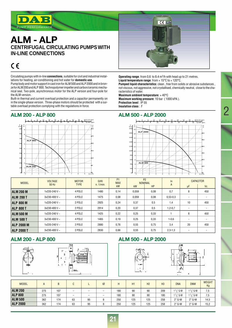
ALM - ALPCENTRIFUGAL CIRCULATING PUMPS WITHIN-LINE CONNECTIONS
Circulating pumps with in-line connections, suitable for civil and industrial instal-lations for heating, air-conditioning and hot water for domestic use.Pump body and motor support in cast iron for ALM 500 and ALP 2000 and in bron-ze for ALM 200 and ALP 800. Technopolymer impeller and carbon/ceramic mecha-nical seal. Two-pole, asynchronous motor for the ALP version and four-pole forthe ALM version.Built-in thermal and current overload protection and a capacitor permanently onin the single-phase version. Three-phase motors should be protected with a sui-table overload protection complying with the regulations in force.
Operating range: from 0,6 to 8.4 m3/h with head up to 21 metres.Liquid temperature range: from + 15°C to + 120°C.Pumped liquid characteristics: clean , free from solids or abrasive substances ,not viscous, not aggressive, not crystallised, chemically neutral, close to the cha-racteristics of water.Maximum ambient temperature: + 40°CMaximum working pressure: 10 bar ( 1000 kPA ).Protection level : IP 55 Insulation class : F
0 1 2 3 4 5 6 7 8 9 Q m3/h0
1
2
3
4
5
6
7
8
9
Hm
0
10
20
30
40
50
60
70
80
90
PkPa
0
5
10
15
20
25
30
H ft
0 4 8 12 16 20 24 28 32 36 40 Q US gpm
0 4 8 12 16 20 24 28 32 Q IMP gpm
ALM 200
ALP 800
ALM 200 - ALP 800 ALM 500 - ALP 2000
ALM 200 - ALP 800 ALM 500 - ALP 2000
MODEL
ALM 200 M
ALM 200 T
ALP 800 M
ALP 800 T
ALM 500 M
ALM 500 T
ALP 2000 M
ALP 2000 T
VOLTAGE50 Hz
MOTORTYPE
GIRIn. 1/min.
P1MAXkW
InA
1x220-240 V ~
3x230-400 V ~
1x220-240 V ~
3x230-400 V ~
1x220-240 V ~
3x230-400 V ~
1x220-240 V ~
3x230-400 V ~
4 POLE
4 POLE
2 POLE
2 POLE
4 POLE
4 POLE
2 POLE
2 POLE
1480
1475
2925
2914
1425
1465
2880
2830
0,14
0,08
0,24
0,20
0,22
0,19
0,76
0,66
0,059
0,059
0,37
0,37
0,25
0,25
0,55
0,55
0,08
0,08
0,5
0,5
0,33
0,33
0,75
0,75
0,7
0,53-0,3
1,4
1,2-0,7
1
1-0,6
3,4
2,3-1,3
8
-
10
-
8
-
20
-
450
-
450
-
450
-
450
-
P2NOMINAL
kW HP
CAPACITOR
µF Vc
ALM 200 275 107 – – – 180 90 90 209 1 1/2” G-M 1 1/2” G-M 7,5
ALP 800 275 107 – – – 180 90 90 180 1 1/2” G-M 1 1/2” G-M 7,5
ALM 500 362 174 63 95 8 250 125 125 258 2” G-M 2” G-M 14,5
ALP 2000 362 174 63 95 8 250 125 125 258 2” G-M 2” G-M 15,2
MODEL A B C L IØ H H1 H2 H3 DNA DNM WEIGHTKg
0 1 2 3 4 5 6 7 8 9 Q m3/h0
2
4
6
8
10
12
14
16
18
20
Hm
0
20
40
60
80
100
120
140
160
180
200
PkPa
0
10
20
30
40
50
60
H ft
0 4 8 12 16 20 24 28 32 36 40 Q US gpm
0 4 8 12 16 20 24 28 32 Q IMP gpm
ALM 500
ALP 2000
®
22
2
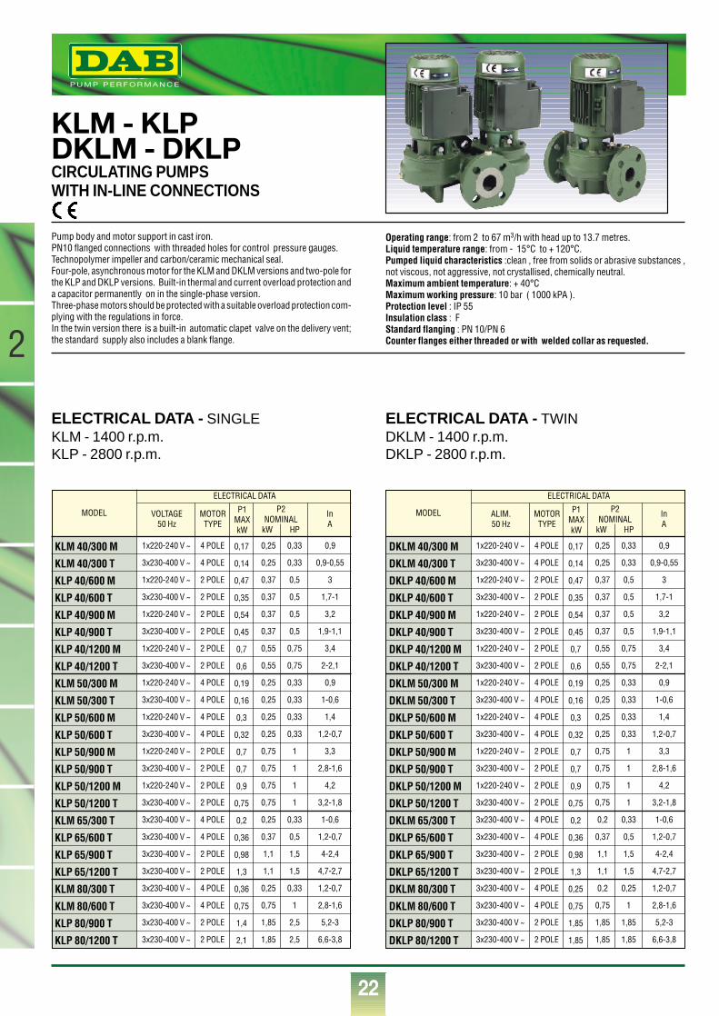
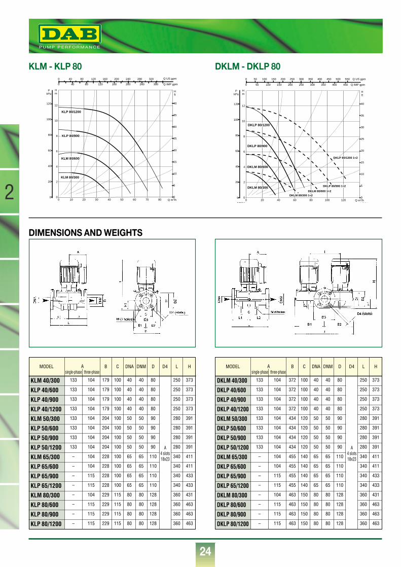
KLM - KLPDKLM - DKLPCIRCULATING PUMPSWITH IN-LINE CONNECTIONS
Pump body and motor support in cast iron.PN10 flanged connections with threaded holes for control pressure gauges.Technopolymer impeller and carbon/ceramic mechanical seal.Four-pole, asynchronous motor for the KLM and DKLM versions and two-pole forthe KLP and DKLP versions. Built-in thermal and current overload protection anda capacitor permanently on in the single-phase version.Three-phase motors should be protected with a suitable overload protection com-plying with the regulations in force.In the twin version there is a built-in automatic clapet valve on the delivery vent;the standard supply also includes a blank flange.
Operating range: from 2 to 67 m3/h with head up to 13.7 metres.Liquid temperature range: from - 15°C to + 120°C.Pumped liquid characteristics :clean , free from solids or abrasive substances ,not viscous, not aggressive, not crystallised, chemically neutral.Maximum ambient temperature: + 40°CMaximum working pressure: 10 bar ( 1000 kPA ).Protection level : IP 55 Insulation class : FStandard flanging : PN 10/PN 6 Counter flanges either threaded or with welded collar as requested.
ELECTRICAL DATA - SINGLEKLM - 1400 r.p.m.KLP - 2800 r.p.m.
ELECTRICAL DATA - TWINDKLM - 1400 r.p.m.DKLP - 2800 r.p.m.
MODEL
KLM 40/300 M
KLM 40/300 T
KLP 40/600 M
KLP 40/600 T
KLP 40/900 M
KLP 40/900 T
KLP 40/1200 M
KLP 40/1200 T
KLM 50/300 M
KLM 50/300 T
KLP 50/600 M
KLP 50/600 T
KLP 50/900 M
KLP 50/900 T
KLP 50/1200 M
KLP 50/1200 T
KLM 65/300 T
KLP 65/600 T
KLP 65/900 T
KLP 65/1200 T
KLM 80/300 T
KLM 80/600 T
KLP 80/900 T
KLP 80/1200 T
VOLTAGE50 Hz
MOTORTYPE
P1MAXkW
InA
1x220-240 V ~
3x230-400 V ~
1x220-240 V ~
3x230-400 V ~
1x220-240 V ~
3x230-400 V ~
1x220-240 V ~
3x230-400 V ~
1x220-240 V ~
3x230-400 V ~
1x220-240 V ~
3x230-400 V ~
1x220-240 V ~
3x230-400 V ~
1x220-240 V ~
3x230-400 V ~
3x230-400 V ~
3x230-400 V ~
3x230-400 V ~
3x230-400 V ~
3x230-400 V ~
3x230-400 V ~
3x230-400 V ~
3x230-400 V ~
4 POLE
4 POLE
2 POLE
2 POLE
2 POLE
2 POLE
2 POLE
2 POLE
4 POLE
4 POLE
4 POLE
4 POLE
2 POLE
2 POLE
2 POLE
2 POLE
4 POLE
4 POLE
2 POLE
2 POLE
4 POLE
4 POLE
2 POLE
2 POLE
0,17
0,14
0,47
0,35
0,54
0,45
0,7
0,6
0,19
0,16
0,3
0,32
0,7
0,7
0,9
0,75
0,2
0,36
0,98
1,3
0,36
0,75
1,4
2,1
0,25
0,25
0,37
0,37
0,37
0,37
0,55
0,55
0,25
0,25
0,25
0,25
0,75
0,75
0,75
0,75
0,25
0,37
1,1
1,1
0,25
0,75
1,85
1,85
0,33
0,33
0,5
0,5
0,5
0,5
0,75
0,75
0,33
0,33
0,33
0,33
1
1
1
1
0,33
0,5
1,5
1,5
0,33
1
2,5
2,5
0,9
0,9-0,55
3
1,7-1
3,2
1,9-1,1
3,4
2-2,1
0,9
1-0,6
1,4
1,2-0,7
3,3
2,8-1,6
4,2
3,2-1,8
1-0,6
1,2-0,7
4-2,4
4,7-2,7
1,2-0,7
2,8-1,6
5,2-3
6,6-3,8
ELECTRICAL DATA
P2NOMINAL
kW HP
MODEL
DKLM 40/300 M
DKLM 40/300 T
DKLP 40/600 M
DKLP 40/600 T
DKLP 40/900 M
DKLP 40/900 T
DKLP 40/1200 M
DKLP 40/1200 T
DKLM 50/300 M
DKLM 50/300 T
DKLP 50/600 M
DKLP 50/600 T
DKLP 50/900 M
DKLP 50/900 T
DKLP 50/1200 M
DKLP 50/1200 T
DKLM 65/300 T
DKLP 65/600 T
DKLP 65/900 T
DKLP 65/1200 T
DKLM 80/300 T
DKLM 80/600 T
DKLP 80/900 T
DKLP 80/1200 T
ALIM.50 Hz
MOTORTYPE
P1MAXkW
InA
1x220-240 V ~
3x230-400 V ~
1x220-240 V ~
3x230-400 V ~
1x220-240 V ~
3x230-400 V ~
1x220-240 V ~
3x230-400 V ~
1x220-240 V ~
3x230-400 V ~
1x220-240 V ~
3x230-400 V ~
1x220-240 V ~
3x230-400 V ~
1x220-240 V ~
3x230-400 V ~
3x230-400 V ~
3x230-400 V ~
3x230-400 V ~
3x230-400 V ~
3x230-400 V ~
3x230-400 V ~
3x230-400 V ~
3x230-400 V ~
4 POLE
4 POLE
2 POLE
2 POLE
2 POLE
2 POLE
2 POLE
2 POLE
4 POLE
4 POLE
4 POLE
4 POLE
2 POLE
2 POLE
2 POLE
2 POLE
4 POLE
4 POLE
2 POLE
2 POLE
4 POLE
4 POLE
2 POLE
2 POLE
0,17
0,14
0,47
0,35
0,54
0,45
0,7
0,6
0,19
0,16
0,3
0,32
0,7
0,7
0,9
0,75
0,2
0,36
0,98
1,3
0,25
0,75
1,85
1,85
0,25
0,25
0,37
0,37
0,37
0,37
0,55
0,55
0,25
0,25
0,25
0,25
0,75
0,75
0,75
0,75
0,2
0,37
1,1
1,1
0,2
0,75
1,85
1,85
0,33
0,33
0,5
0,5
0,5
0,5
0,75
0,75
0,33
0,33
0,33
0,33
1
1
1
1
0,33
0,5
1,5
1,5
0,25
1
1,85
1,85
0,9
0,9-0,55
3
1,7-1
3,2
1,9-1,1
3,4
2-2,1
0,9
1-0,6
1,4
1,2-0,7
3,3
2,8-1,6
4,2
3,2-1,8
1-0,6
1,2-0,7
4-2,4
4,7-2,7
1,2-0,7
2,8-1,6
5,2-3
6,6-3,8
ELECTRICAL DATA
P2NOMINAL
kW HP
®
23
2
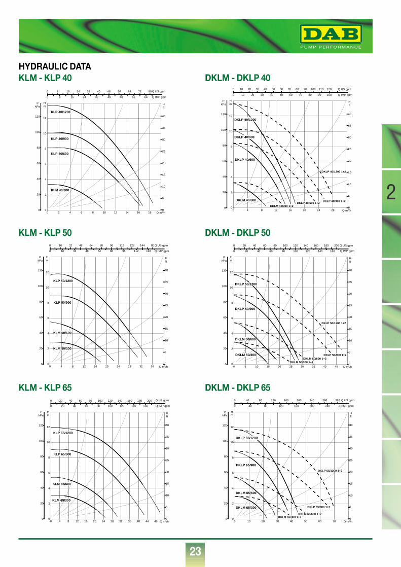
KLM - KLP 65 DKLM - DKLP 65
KLM - KLP 50 DKLM - DKLP 50
KLM - KLP 40HYDRAULIC DATA
DKLM - DKLP 40
0 2 4 6 8 10 12 14 16 18 Q m3/h0
2
4
6
8
10
12
Hm
0
20
40
60
80
100
120
PkPa
0
5
10
15
20
25
30
35
40
H ft
0 8 16 24 32 40 48 56 64 72 80 Q US gpm
0 8 16 24 32 40 48 56 64 Q IMP gpm
KLM 40/300
KLP 40/1200
KLP 40/600
KLP 40/900
0 Q m3/h4 8 12 16 20 24 280
2
4
6
8
10
12
Hm
0
20
40
60
80
100
120
PkPa
0
5
10
15
20
25
30
35
40
H ft
0 10 20 30 40 50 60 70 80 90 100 110 120 Q US gpm
0 10 20 30 40 50 60 70 80 90 100 Q IMP gpm
DKLM 40/300
DKLP 40/600
DKLM 40/300 1+2DKLP 40/600 1+2
DKLP 40/900 1+2
DKLP 40/1200 1+2
DKLP 40/1200
DKLP 40/900
0 4 8 12 16 20 24 28 32 36 Q m3/h0
2
4
6
8
10
12
Hm
0
20
40
60
80
100
120
PkPa
0
5
10
15
20
25
30
35
40
H ft
0 16 32 48 64 80 96 112 128 144 80 Q US gpm
0 16 32 48 64 80 96 112 128 Q IMP gpm
KLM 50/300
KLP 50/1200
KLM 50/600
KLP 50/900
0 5 10 15 20 25 30 35 40 45 Q m3/h0
2
4
6
8
10
12
Hm
0
20
40
60
80
100
120
PkPa
0
5
10
15
20
25
30
35
40
H ft
0 20 40 60 80 100 120 140 160 180 200 Q US gpm
0 20 40 60 80 100 120 140 160 Q IMP gpm
DKLM 50/300
DKLM 50/600
DKLP 50/900
DKLM 50/600 1+2DKLM 50/300 1+2
DKLP 50/900 1+2
DKLP 50/1200 1+2
DKLP 50/1200
0 4 8 12 16 20 24 28 32 36 40 44 48 Q m3/h0
2
4
6
8
10
12
Hm
0
20
40
60
80
100
120
PkPa
0
5
10
15
20
25
30
35
40
H ft
0 20 40 60 80 100 120 140 160 180 200 Q US gpm
0 20 40 60 80 100 120 140 160 Q IMP gpm
KLM 65/300
KLP 65/1200
KLM 65/600
KLP 65/900
0 Q m3/h10 20 30 40 50 60 700
2
4
6
8
10
12
Hm
0
20
40
60
80
100
120
PkPa
0
5
10
15
20
25
30
35
40
H ft
0 40 80 120 160 200 240 280 320 Q US gpm
0 40 80 120 160 200 240 Q IMP gpm
DKLM 65/300
DKLM 65/600
DKLP 65/900
DKLM 65/300 1+2DKLM 65/600 1+2
DKLP 65/900 1+2
DKLP 65/1200 1+2
DKLP 65/1200
®
24
2
KLM - KLP 80 DKLM - DKLP 80
DIMENSIONS AND WEIGHTS
MODEL
KLM 40/300
KLP 40/600
KLP 40/900
KLP 40/1200
KLM 50/300
KLP 50/600
KLP 50/900
KLP 50/1200
KLM 65/300
KLP 65/600
KLP 65/900
KLP 65/1200
KLM 80/300
KLP 80/600
KLP 80/900
KLP 80/1200
B C DNA DNM D D4 L H
133
133
133
133
133
133
133
133
–
–
–
–
–
–
–
–
104
104
104
104
104
104
104
104
104
104
115
115
104
115
115
115
179
179
179
179
204
204
204
204
228
228
228
228
229
229
229
229
100
100
100
100
100
100
100
100
100
100
100
100
115
115
115
115
40
40
40
40
50
50
50
50
65
65
65
65
80
80
80
80
40
40
40
40
50
50
50
50
65
65
65
65
80
80
80
80
80
80
80
80
90
90
90
90
110
110
110
110
128
128
128
128
250
250
250
250
280
280
280
280
340
340
340
340
360
360
360
360
373
373
373
373
391
391
391
391
411
411
433
433
431
463
463
463
A4 slots18x23
Asingle-phase three-phase
MODEL
DKLM 40/300
DKLP 40/600
DKLP 40/900
DKLP 40/1200
DKLM 50/300
DKLP 50/600
DKLP 50/900
DKLP 50/1200
DKLM 65/300
DKLP 65/600
DKLP 65/900
DKLP 65/1200
DKLM 80/300
DKLP 80/600
DKLP 80/900
DKLP 80/1200
B C DNA DNM D D4 L H
133
133
133
133
133
133
133
133
–
–
–
–
–
–
–
–
104
104
104
104
104
104
104
104
104
104
115
115
104
115
115
115
372
372
372
372
434
434
434
434
455
455
455
455
463
463
463
463
100
100
100
100
120
120
120
120
140
140
140
140
150
150
150
150
40
40
40
40
50
50
50
50
65
65
65
65
80
80
80
80
40
40
40
40
50
50
50
50
65
65
65
65
80
80
80
80
80
80
80
80
90
90
90
90
110
110
110
110
128
128
128
128
250
250
250
250
280
280
280
280
340
340
340
340
360
360
360
360
373
373
373
373
391
391
391
391
411
411
433
433
431
463
463
463
A4 slots18x23
Asingle-phase three-phase
0 Q m3/h10 20 30 40 50 60 70 800
2
4
6
8
10
12
Hm
0
20
40
60
80
100
120
PkPa
0
5
10
15
20
25
30
35
40
H ft
0 40 80 120 160 200 240 280 320 Q US gpm
0 40 80 120 160 200 240 300 Q IMP gpm
KLM 80/300
KLP 80/1200
KLM 80/600
KLP 80/900
0 Q m3/h20 40 60 80 100 1200
2
4
6
8
10
12
Hm
0
20
40
60
80
100
120
PkPa
NPSH
0
5
10
15
20
25
30
35
40
H ft
0 50 100 150 200 250 300 350 400 450 500 550 Q US gpm
0 50 100 150 200 250 300 350 400 450 Q IMP gpm
NPSH
DKLM 80/300
DKLP 80/1200
DKLM 80/600
DKLP 80/900
DKLM 80/300 1+2
DKLM 80/600 1+2
DKLP 80/900 1+2
DKLP 80/1200 1+2
®
25
2ELECTRICAL DATA
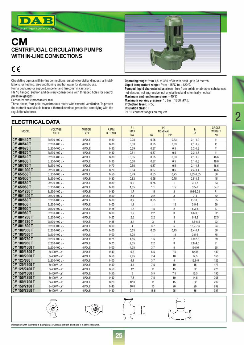
CMCENTRIFUGAL CIRCULATING PUMPSWITH IN-LINE CONNECTIONS
Circulating pumps with in-line connections, suitable for civil and industrial instal-lations for heating, air-conditioning and hot water for domestic use. Pump body, motor support, impeller and fan cover in cast iron.PN 16 flanged suction and delivery connections with threaded holes for controlpressure gauges.Carbon/ceramic mechanical seal.Three-phase, four-pole, asynchronous motor with external ventilation. To protectthe motor it is advisable to use a thermal overload protection complying with theregulations in force.
Operating range: from 1,5 to 360 m3/h with head up to 23 metres.Liquid temperature range:: from - 15°C to + 120°C.Pumped liquid characteristics :clean , free from solids or abrasive substances,not viscous, not aggressive, not crystallised and chemically neutral.Maximum ambient temperature: + 40°CMaximum working pressure: 16 bar ( 1600 kPA ).Protection level : IP 55 Insulation class : FPN 16 counter flanges on request.
Installation: with the motor in a horizontal or vertical position as long as it is above the pump.
MODEL
CM 40/440 TCM 40/540 TCM 40/670 TCM 40/870 TCM 50/510 TCM 50/630 TCM 50/780 TCM 50/1000 TCM 65/550 TCM 65/650 TCM 65/850 TCM 65/960 TCM 65/1280 TCM 65/1400 TCM 80/560 TCM 80/650 TCM 80/900 TCM 80/980 TCM 80/1200 TCM 80/1330 TCM 80/1500 TCM 100/350 TCM 100/550 TCM 100/750 TCM 100/950 TCM 100/1500 TCM 100/1800 TCM 100/2000 TCM 125/880 TCM 125/1500 TCM 125/2400 TCM 150/1000 TCM 150/1250 TCM 150/1700 TCM 150/2100 TCM 150/2350 T
VOLTAGE50 Hz
MOTORTYPE
R.P.M.n. 1/min.
P1MAXkW
InA
3x230-400 V ~3x230-400 V ~3x230-400 V ~3x230-400 V ~3x230-400 V ~3x230-400 V ~3x230-400 V ~3x230-400 V ~3x230-400 V ~3x230-400 V ~3x230-400 V ~3x230-400 V ~3x230-400 V ~3x230-400 V ~3x230-400 V ~3x230-400 V ~3x230-400 V ~3x230-400 V ~3x230-400 V ~3x230-400 V ~3x230-400 V ~3x230-400 V ~3x230-400 V ~3x230-400 V ~3x230-400 V ~3x230-400 V ~3x400 V ~ ∆*3x400 V ~ ∆*
3x230-400 V ~3x400 V ~ ∆*3x400 V ~ ∆*3x400 V ~ ∆*3x400 V ~ ∆*3x400 V ~ ∆*3x400 V ~ ∆*3x400 V ~ ∆*
4 POLE4 POLE4 POLE4 POLE4 POLE4 POLE4 POLE4 POLE4 POLE4 POLE4 POLE4 POLE4 POLE4 POLE4 POLE4 POLE4 POLE4 POLE4 POLE4 POLE4 POLE4 POLE4 POLE4 POLE4 POLE4 POLE4 POLE4 POLE4 POLE4 POLE4 POLE4 POLE4 POLE4 POLE4 POLE4 POLE
148014801480148014801480147014701450143014301430143014501400140014251400142514351400140014001425142514001440145014001450145014501450142014401450
0,280,330,390,510,350,500,500,640,490,620,91,051,72,10,91,11,71,92,63,44
0,651,051,552,354,756,67,954,18,4125
7,812,316,821,1
0,250,250,370,370,250,370,370,370,550,550,751,11,52,20,751,11,52,22,23
3,70,551,11,52,23,75,57,43,77,5115,57,51115
18,5
0,330,330,50,50,330,50,50,50,750,75
11,5231
1,523345
0,751,5235
7,510510157,510152025
2,1-1,22,1-1,22,2-1,32,2-1,32,1-1,22,1-1,32,1-1,32,4-1,4
2,33-1,352,5-1,53-1,73,5-2
5,6-3,237-4
2,7-1,63,5-25,3-3
6,6-3,88-4,8
11,5-6,513,2-7,62,4-1,43,5-2
4,9-2,87,8-4,515-8,612,3614,5
13,8-81522
10,514,5222935
41414141
46,646,646,646,6504563
64,7717265608782
87,592946075899195140150125173225190206292292327
P2NOMINAL
kW HP
GROSSWEIGHT
Kg
®
26
2
CM 125 CM 150
CM 80 CM 100
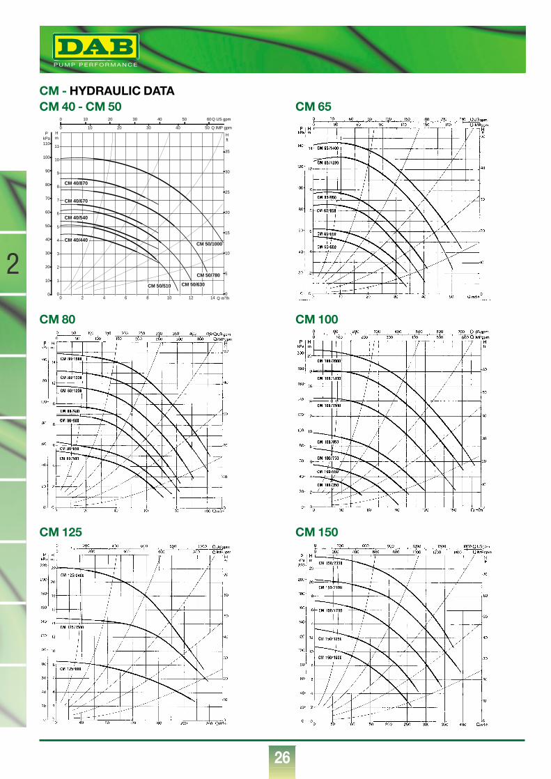
CM - HYDRAULIC DATACM 65CM 40 - CM 50
0 2 4 6 8 10 12 14 Q m3/h0
1
2
3
4
5
6
7
8
9
10
11
Hm
0
10
20
30
40
50
60
70
80
90
100
110
PkPa
0
5
10
15
20
25
30
35
H ft
0 10 20 30 40 50 60 Q US gpm
0 10 20 30 40 50 Q IMP gpm
CM 40/440
CM 50/510 CM 50/630
CM 50/780
CM 50/1000
CM 40/540
CM 40/670
CM 40/870
®
27
2
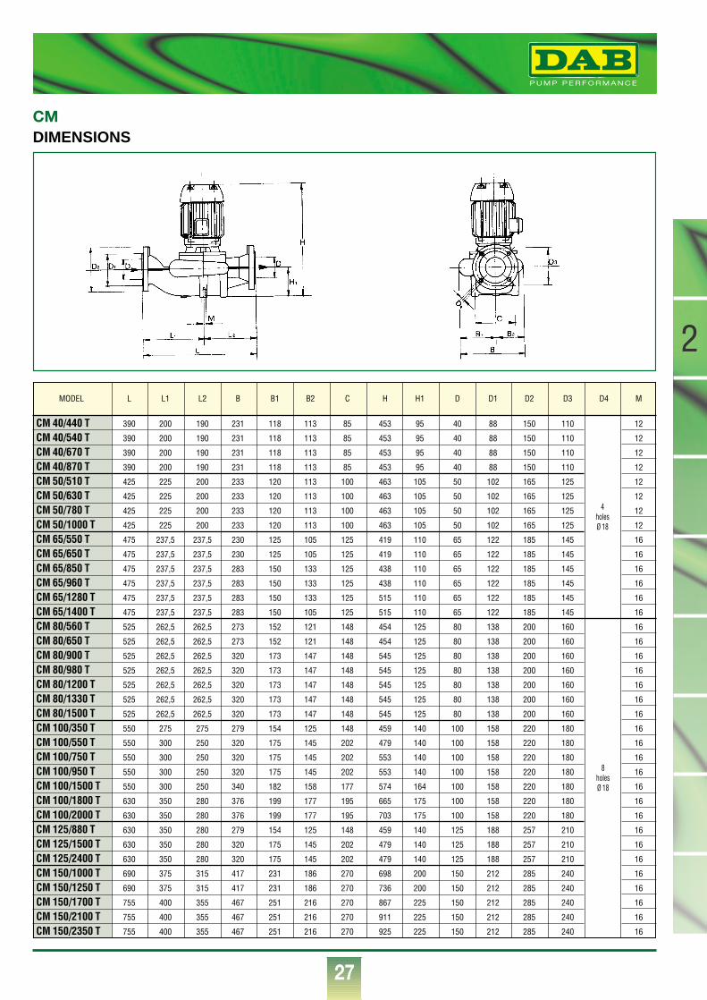
DIMENSIONSCM
CM 40/440 T 390 200 190 231 118 113 85 453 95 40 88 150 110 12
CM 40/540 T 390 200 190 231 118 113 85 453 95 40 88 150 110 12
CM 40/670 T 390 200 190 231 118 113 85 453 95 40 88 150 110 12
CM 40/870 T 390 200 190 231 118 113 85 453 95 40 88 150 110 12
CM 50/510 T 425 225 200 233 120 113 100 463 105 50 102 165 125 12
CM 50/630 T 425 225 200 233 120 113 100 463 105 50 102 165 125 12
CM 50/780 T 425 225 200 233 120 113 100 463 105 50 102 165 125 12
CM 50/1000 T 425 225 200 233 120 113 100 463 105 50 102 165 125 12
CM 65/550 T 475 237,5 237,5 230 125 105 125 419 110 65 122 185 145 16
CM 65/650 T 475 237,5 237,5 230 125 105 125 419 110 65 122 185 145 16
CM 65/850 T 475 237,5 237,5 283 150 133 125 438 110 65 122 185 145 16
CM 65/960 T 475 237,5 237,5 283 150 133 125 438 110 65 122 185 145 16
CM 65/1280 T 475 237,5 237,5 283 150 133 125 515 110 65 122 185 145 16
CM 65/1400 T 475 237,5 237,5 283 150 105 125 515 110 65 122 185 145 16
CM 80/560 T 525 262,5 262,5 273 152 121 148 454 125 80 138 200 160 16
CM 80/650 T 525 262,5 262,5 273 152 121 148 454 125 80 138 200 160 16
CM 80/900 T 525 262,5 262,5 320 173 147 148 545 125 80 138 200 160 16
CM 80/980 T 525 262,5 262,5 320 173 147 148 545 125 80 138 200 160 16
CM 80/1200 T 525 262,5 262,5 320 173 147 148 545 125 80 138 200 160 16
CM 80/1330 T 525 262,5 262,5 320 173 147 148 545 125 80 138 200 160 16
CM 80/1500 T 525 262,5 262,5 320 173 147 148 545 125 80 138 200 160 16
CM 100/350 T 550 275 275 279 154 125 148 459 140 100 158 220 180 16
CM 100/550 T 550 300 250 320 175 145 202 479 140 100 158 220 180 16
CM 100/750 T 550 300 250 320 175 145 202 553 140 100 158 220 180 16
CM 100/950 T 550 300 250 320 175 145 202 553 140 100 158 220 180 16
CM 100/1500 T 550 300 250 340 182 158 177 574 164 100 158 220 180 16
CM 100/1800 T 630 350 280 376 199 177 195 665 175 100 158 220 180 16
CM 100/2000 T 630 350 280 376 199 177 195 703 175 100 158 220 180 16
CM 125/880 T 630 350 280 279 154 125 148 459 140 125 188 257 210 16
CM 125/1500 T 630 350 280 320 175 145 202 479 140 125 188 257 210 16
CM 125/2400 T 630 350 280 320 175 145 202 479 140 125 188 257 210 16
CM 150/1000 T 690 375 315 417 231 186 270 698 200 150 212 285 240 16
CM 150/1250 T 690 375 315 417 231 186 270 736 200 150 212 285 240 16
CM 150/1700 T 755 400 355 467 251 216 270 867 225 150 212 285 240 16
CM 150/2100 T 755 400 355 467 251 216 270 911 225 150 212 285 240 16
CM 150/2350 T 755 400 355 467 251 216 270 925 225 150 212 285 240 16
MODEL L L1 L2 B B1 B2 C H H1 D D1 D2 D3 D4 M
4holesØ 18
8holesØ 18
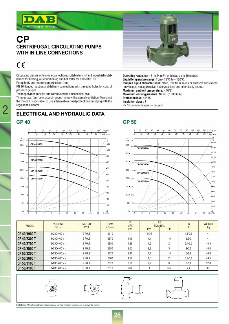
®
28
2
CPCENTRIFUGAL CIRCULATING PUMPSWITH IN-LINE CONNECTIONS
Circulating pumps with in-line connections, suitable for civil and industrial instal-lations for heating, air-conditioning and hot water for domestic use. Pump body and motor support in cast iron.PN 16 flanged suction and delivery connections with threaded holes for controlpressure gauges.Technopolymer impeller and carbon/ceramic mechanical seal.Three-phase, four-pole, asynchronous motor with external ventilation. To protectthe motor it is advisable to use a thermal overload protection complying with theregulations in force.
Operating range: from 3 to 24 m3/h with head up to 40 metres.Liquid temperature range: from - 15°C to + 120°C.Pumped liquid characteristics: clean, free from solids or abrasive substances,not viscous, not aggressive, not crystallised and chemically neutral.Maximum ambient temperature: + 40°CMaximum working pressure: 16 bar ( 1600 kPA ).Protection level : IP 55 Insulation class : FPN 16 counter flanges on request.
CP 40
ELECTRICAL AND HYDRAULIC DATA
CP 50
MODEL
CP 40/1900 TCP 40/2300 TCP 40/2700 TCP 40/3500 TCP 50/2200 TCP 50/2600 TCP 50/3100 TCP 50/4100 T
VOLTAGE50 Hz
MOTORTYPE
R.P.M.n. 1/min.
P1MAXkW
InA
3x230-400 V ~
3x230-400 V ~
3x230-400 V ~
3x230-400 V ~
3x230-400 V ~
3x230-400 V ~
3x230-400 V ~
3x230-400 V ~
2 POLE
2 POLE
2 POLE
2 POLE
2 POLE
2 POLE
2 POLE
2 POLE
2910
2870
2850
2880
2870
2860
2870
2910
1,1
1,45
1,89
2,53
1,42
1,89
2,51
3,8
0,75
1,1
1,5
2,2
1,1
1,5
2,2
4
1
1,5
2
3
1,5
2
3
5,5
4,5-2,6
5,2-3
6,4-3,7
9-5,2
5-2,9
6,2-3,6
9-5,2
7,4
41
41
43,5
48,8
46,6
49,5
52,8
61
P2NOMINAL
kW HP
WEIGHTKg
0 2 4 6 8 10 12 14 16 18 Q m3/h0
4
8
12
16
20
24
28
32
Hm
0
40
80
120
160
200
240
280
320
PkPa
NPSH
0
10
20
30
40
50
60
70
80
90
100
110
H ft
0 8 16 24 32 40 48 56 64 72 80 Q US gpm
0 8 16 24 32 40 48 56 64 Q IMP gpm
NPSH
CP 40/1900
CP 40/3500
CP 40/2300
CP 40/2700
0 3 6 9 12 15 18 21 24 27 Q m3/h0
5
10
15
20
25
30
35
40
Hm
0
50
100
150
200
250
300
350
400
PkPa
0
10
20
30
40
50
60
70
80
90
100
110
120
130
140
H ft
0 10 20 30 40 50 60 70 80 90 100 110 120 Q US gpm
0 10 20 30 40 50 60 70 80 90 100 Q IMP gpm
CP 50/2200
CP 50/4100
CP 50/2600
CP 50/3100
Installation: With the motor in a horizontal or vertical position as long as it is above the pump.
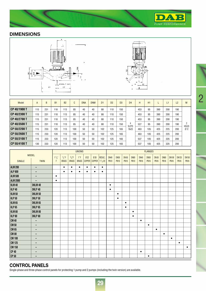
®
29
2
DIMENSIONS
CONTROL PANELSSingle-phase and three-phase control panels for protecting 1 pump and 2 pumps (including the twin version) are available.
CP 40/1900 T 115 231 118 113 85 40 40 88 110 150 453 95 390 200 190
CP 40/2300 T 115 231 118 113 85 40 40 88 110 150 453 95 390 200 190
CP 40/2700 T 115 231 118 113 85 40 40 88 110 150 453 95 390 200 190
CP 40/3500 T 115 231 118 113 85 40 40 88 110 150 527 95 390 200 190
CP 50/2200 T 115 233 120 113 100 50 50 102 125 165 463 105 425 225 200
CP 50/2600 T 115 233 120 113 100 50 50 102 125 165 463 105 425 225 200
CP 50/3100 T 115 233 120 113 100 50 50 102 125 165 537 105 425 225 200
CP 50/4100 T 130 233 120 113 100 50 50 102 125 165 537 105 425 225 200
Model A B B1 B2 C DNA DNM D1 D2 D3 D4 H H1 L L1 L2 M
4SLOTS18x23
2HOLESØ 12
ALM 200 – • • • • • •ALP 800 – • • • • • •ALM 500 – •ALM 2000 – •KLM 40 DKLM 40 •KLP 40 DKLP 40 •KLM 50 DKLM 50 •KLP 50 DKLP 50 •KLM 65 DKLM 65 •KLP 65 DKLP 65 •KLM 80 DKLM 80 •KLP 80 DKLP 80 •CM 40 – •CM 50 – •CM 65 – •CM 80 – •CM 100 – •CM 125 – •CM 150 – •CP 40 – •CP 50 – •
1 1/4” 1/2” F 3/4”F 1” F Ø 22 Ø 28 REDUC.. DN40 DN50 DN 65 DN80 DN40 DN50 DN 65 DN80 DN100 DN125 DN150F BRASS BRASS BRASS COPPER COPPER 1 1/2-22 PN10 PN10 PN10 PN10 PN16 PN16 PN16 PN16 PN16 PN16 PN16
UNIONS
MODEL
SINGLE TWIN
FLANGES
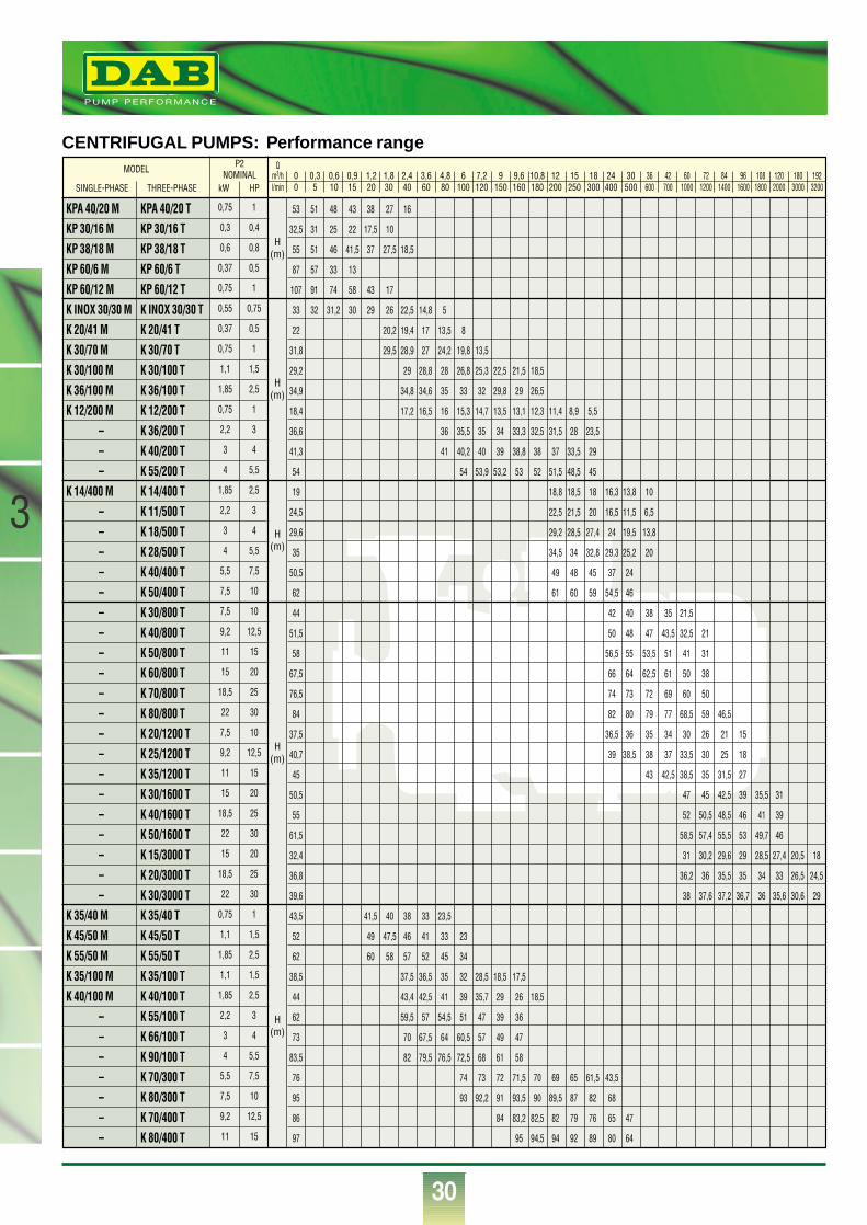
®
30
3
CENTRIFUGAL PUMPS: Performance rangeQ
m3/h 0 0,3 0,6 0,9 1,2 1,8 2,4 3,6 4,8 6 7,2 9 9,6 10,8 12 15 18 24 30l/min 0 5 10 15 20 30 40 60 80 100 120 150 160 180 200 250 300 400 500
36 42 60 72 84 96 108 120 180 192600 700 1000 1200 1400 1600 1800 2000 3000 3200
53 51 48 43 38 27 16
32,5 31 25 22 17,5 10
55 51 46 41,5 37 27,5 18,5
87 57 33 13
107 91 74 58 43 17
33 32 31,2 30 29 26 22,5 14,8 5
22 20,2 19,4 17 13,5 8
31,8 29,5 28,9 27 24,2 19,8 13,5
29,2 29 28,8 28 26,8 25,3 22,5 21,5 18,5
34,9 34,8 34,6 35 33 32 29,8 29 26,5
18,4 17,2 16,5 16 15,3 14,7 13,5 13,1 12,3 11,4 8,9 5,5
36,6 36 35,5 35 34 33,3 32,5 31,5 28 23,5
41,3 41 40,2 40 39 38,8 38 37 33,5 29
54 54 53,9 53,2 53 52 51,5 48,5 45
19 18,8 18,5 18 16,3 13,8 10
24,5 22,5 21,5 20 16,5 11,5 6,5
29,6 29,2 28,5 27,4 24 19,5 13,8
35 34,5 34 32,8 29,3 25,2 20
50,5 49 48 45 37 24
62 61 60 59 54,5 46
44 42 40 38
51,5 50 48 47
58 56,5 55 53,5
67,5 66 64 62,5
76,5 74 73 72
84 82 80 79
37,5 36,5 36 35
40,7 39 38,5 38
45 43
50,5
55
61,5
32,4
36,8
39,6
43,5 41,5 40 38 33 23,5
52 49 47,5 46 41 33 23
62 60 58 57 52 45 34
38,5 37,5 36,5 35 32 28,5 18,5 17,5
44 43,4 42,5 41 39 35,7 29 26 18,5
62 59,5 57 54,5 51 47 39 36
73 70 67,5 64 60,5 57 49 47
83,5 82 79,5 76,5 72,5 68 61 58
76 74 73 72 71,5 70 69 65 61,5 43,5
95 93 92,2 91 93,5 90 89,5 87 82 68
86 84 83,2 82,5 82 79 76 65 47
97 95 94,5 94 92 89 80 64
35 21,5
43,5 32,5 21
51 41 31
61 50 38
69 60 50
77 68,5 59 46,5
34 30 26 21 15
37 33,5 30 25 18
42,5 38,5 35 31,5 27
47 45 42,5 39 35,5 31
52 50,5 48,5 46 41 39
58,5 57,4 55,5 53 49,7 46
31 30,2 29,6 29 28,5 27,4 20,5 18
36,2 36 35,5 35 34 33 26,5 24,5
38 37,6 37,2 36,7 36 35,6 30,6 29
KPA 40/20 MKP 30/16 MKP 38/18 MKP 60/6 MKP 60/12 MK INOX 30/30 MK 20/41 MK 30/70 MK 30/100 MK 36/100 MK 12/200 M
–––
K 14/400 M––––––––––––––––––––
K 35/40 MK 45/50 MK 55/50 MK 35/100 MK 40/100 M
–––––––
KPA 40/20 TKP 30/16 TKP 38/18 TKP 60/6 TKP 60/12 TK INOX 30/30 TK 20/41 TK 30/70 TK 30/100 TK 36/100 TK 12/200 TK 36/200 TK 40/200 TK 55/200 TK 14/400 TK 11/500 TK 18/500 TK 28/500 TK 40/400 TK 50/400 TK 30/800 TK 40/800 TK 50/800 TK 60/800 TK 70/800 TK 80/800 TK 20/1200 TK 25/1200 TK 35/1200 TK 30/1600 TK 40/1600 TK 50/1600 TK 15/3000 TK 20/3000 TK 30/3000 TK 35/40 TK 45/50 TK 55/50 TK 35/100 TK 40/100 TK 55/100 TK 66/100 TK 90/100 TK 70/300 TK 80/300 TK 70/400 TK 80/400 T
0,75
0,3
0,6
0,37
0,75
0,55
0,37
0,75
1,1
1,85
0,75
2,2
3
4
1,85
2,2
3
4
5,5
7,5
7,5
9,2
11
15
18,5
22
7,5
9,2
11
15
18,5
22
15
18,5
22
0,75
1,1
1,85
1,1
1,85
2,2
3
4
5,5
7,5
9,2
11
1
0,4
0,8
0,5
1
0,75
0,5
1
1,5
2,5
1
3
4
5,5
2,5
3
4
5,5
7,5
10
10
12,5
15
20
25
30
10
12,5
15
20
25
30
20
25
30
1
1,5
2,5
1,5
2,5
3
4
5,5
7,5
10
12,5
15
MODEL
SINGLE-PHASE THREE-PHASE
P2NOMINAL
kW HP
H(m)
H(m)
H(m)
H(m)
H(m)
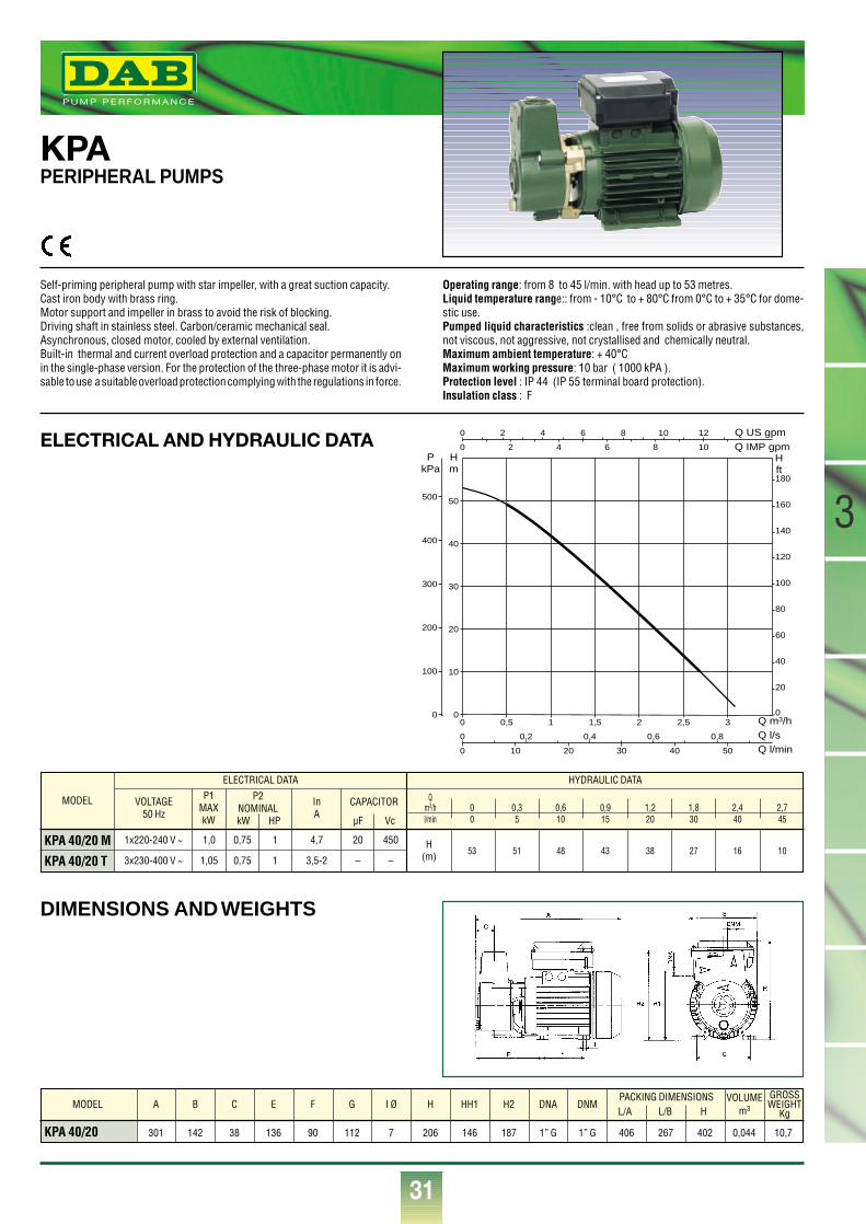
3
31
MODEL
KPA 40/20 M
KPA 40/20 T
VOLTAGE50 Hz
P1MAXkW
InA
1x220-240 V ~
3x230-400 V ~
1,0
1,05
0,75
0,75
1
1
20
–
450
–
H(m)
4,7
3,5-2
ELECTRICAL DATA HYDRAULIC DATA
P2NOMINALkW HP
CAPACITOR
µF Vc
KPAPERIPHERAL PUMPS
Self-priming peripheral pump with star impeller, with a great suction capacity.Cast iron body with brass ring.Motor support and impeller in brass to avoid the risk of blocking. Driving shaft in stainless steel. Carbon/ceramic mechanical seal.Asynchronous, closed motor, cooled by external ventilation.Built-in thermal and current overload protection and a capacitor permanently onin the single-phase version. For the protection of the three-phase motor it is advi-sable to use a suitable overload protection complying with the regulations in force.
Operating range: from 8 to 45 l/min. with head up to 53 metres.Liquid temperature range:: from - 10°C to + 80°C from 0°C to + 35°C for dome-stic use.Pumped liquid characteristics :clean , free from solids or abrasive substances,not viscous, not aggressive, not crystallised and chemically neutral.Maximum ambient temperature: + 40°CMaximum working pressure: 10 bar ( 1000 kPA ).Protection level : IP 44 (IP 55 terminal board protection).Insulation class : F
®
Qm3/h 0 0,3 0,6 0,9 1,2 1,8 2,4 2,7l/min 0 5 10 15 20 30 40 45
53 51 48 43 38 27 16 10
KPA 40/20 301 142 38 136 90 112 7 206 146 187 1” G 1” G 406 267 402 0,044 10,7
MODEL A B C E F G I Ø H HH1 H2 DNA DNMPACKING DIMENSIONSL/A L/B H
GROSSWEIGHT
Kg
VOLUMEm3
ELECTRICAL AND HYDRAULIC DATA
DIMENSIONS AND WEIGHTS
0
0
0 2 4 6 8 10 12
2 4 6 8 10
0 0,2 0,4 0,6 0,8
0,5 1 1,5 2 2,5 3
500 10 20 30 40
Q m3/h
Q IMP gpmQ US gpm
Q l/sQ l/min
0
10
20
30
40
50
0
Hm
PkPa
100
200
300
400
500
0
20
40
60
80
100
120
140
160
180
Hft
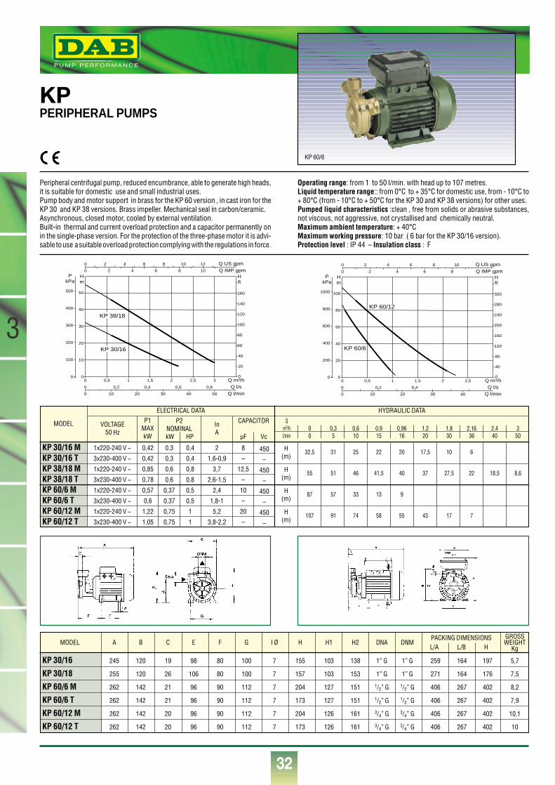
®
32
3
MODEL
KP 30/16 MKP 30/16 TKP 38/18 MKP 38/18 TKP 60/6 MKP 60/6 TKP 60/12 MKP 60/12 T
VOLTAGE50 Hz
P1MAXkW
InA
1x220-240 V ~
3x230-400 V ~
1x220-240 V ~
3x230-400 V ~
1x220-240 V ~
3x230-400 V ~
1x220-240 V ~
3x230-400 V ~
0,42
0,42
0,85
0,78
0,57
0,6
1,22
1,05
0,3
0,3
0,6
0,6
0,37
0,37
0,75
0,75
0,4
0,4
0,8
0,8
0,5
0,5
1
1
8
–
12,5
–
10
–
20
–
450
–
450
–
450
–
450
–
H(m)
H(m)
H(m)
H(m)
2
1,6-0,9
3,7
2,6-1,5
2,4
1,8-1
5,2
3,8-2,2
ELECTRICAL DATA HYDRAULIC DATA
P2NOMINALkW HP
CAPACITOR
µF Vc
KPPERIPHERAL PUMPS
Peripheral centrifugal pump, reduced encumbrance, able to generate high heads,it is suitable for domestic use and small industrial uses. Pump body and motor support in brass for the KP 60 version , in cast iron for theKP 30 and KP 38 versions. Brass impeller. Mechanical seal in carbon/ceramic.Asynchronous, closed motor, cooled by external ventilation.Built-in thermal and current overload protection and a capacitor permanently onin the single-phase version. For the protection of the three-phase motor it is advi-sable to use a suitable overload protection complying with the regulations in force.
Operating range: from 1 to 50 l/min. with head up to 107 metres.Liquid temperature range:: from 0°C to + 35°C for domestic use, from - 10°C to+ 80°C (from - 10°C to + 50°C for the KP 30 and KP 38 versions) for other uses.Pumped liquid characteristics :clean , free from solids or abrasive substances,not viscous, not aggressive, not crystallised and chemically neutral.Maximum ambient temperature: + 40°CMaximum working pressure: 10 bar ( 6 bar for the KP 30/16 version).Protection level : IP 44 – Insulation class : F
Qm3/h 0 0,3 0,6 0,9 0,96 1,2 1,8 2,16 2,4 3l/min 0 5 10 15 16 20 30 36 40 50
32,5 31 25 22 20 17,5 10 6
55 51 46 41,5 40 37 27,5 22 18,5 8,6
87 57 33 13 9
107 91 74 58 55 43 17 7
KP 30/16 245 120 19 98 80 100 7 155 103 138 1” G 1” G 259 164 197 5,7
KP 30/18 255 120 26 106 80 100 7 157 103 153 1” G 1” G 271 164 176 7,5
KP 60/6 M 262 142 21 96 90 112 7 204 127 151 1/2” G 1/2” G 406 267 402 8,2
KP 60/6 T 262 142 21 96 90 112 7 173 127 151 1/2” G 1/2” G 406 267 402 7,9
KP 60/12 M 262 142 20 96 90 112 7 204 126 161 3/4” G 3/4” G 406 267 402 10,1
KP 60/12 T 262 142 20 96 90 112 7 173 126 161 3/4” G 3/4” G 406 267 402 10
MODEL A B C E F G I Ø H H1 H2 DNA DNMPACKING DIMENSIONSL/A L/B H
GROSSWEIGHT
Kg
KP 60/6
0
0
0 2 4 6 8 10 12
2 4 6 8 10
0 0,2 0,4 0,6 0,8
0,5 1 1,5 2 2,5 30
20
40
60
80
100
120
140
160
500 10 20 30 40
Q m3/h
Q IMP gpmQ US gpm
Q l/sQ l/min
0
10
20
30
40
50
0
100
200
300
400
500
Hm
PkPa
Hft
KP 30/16
KP 38/18
0 0,5 1 1,5 2 2,5
0
0
0
0
40
80
120
160
200
240
280
320
0
Q m3/h
Q IMP gpmQ US gpm
Q l/sQ l/min
0
20
40
60
80
100
0
200
400
600
800
1000
Hm
PkPa
0,2 0,4
10 20 30 40
Hft
2 4 6 8 10
2 4 6 8
KP 60/6
KP 60/12
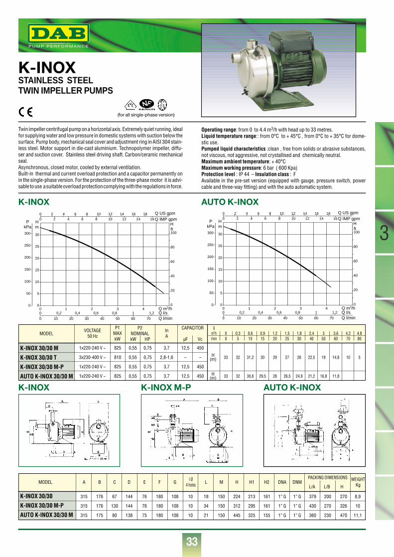
3
33
MODEL
K-INOX 30/30 M
K-INOX 30/30 T
K-INOX 30/30 M-P
AUTO K-INOX 30/30 M
VOLTAGE50 Hz
P1MAXkW
InA
1x220-240 V ~
3x230-400 V ~
1x220-240 V ~
1x220-240 V ~
825
810
825
825
0,55
0,55
0,55
0,55
0,75
0,75
0,75
0,75
12,5
–
12,5
12,5
450
–
450
450
H(m)
H(m)
3,7
2,8-1,6
3,7
3,7
P2NOMINALkW HP
CAPACITOR
µF Vc
K-INOXSTAINLESS STEEL TWIN IMPELLER PUMPS
Twin impeller centrifugal pump on a horizontal axis. Extremely quiet running, idealfor supplying water and low pressure in domestic systems with suction below thesurface. Pump body, mechanical seal cover and adjustment ring in AISI 304 stain-less steel. Motor support in die-cast aluminium. Technopolymer impeller, diffu-ser and suction cover. Stainless steel driving shaft. Carbon/ceramic mechanicalseal. Asynchronous, closed motor, cooled by external ventilation.Built-in thermal and current overload protection and a capacitor permanently onin the single-phase version. For the protection of the three-phase motor it is advi-sable to use a suitable overload protection complying with the regulations in force.
Operating range: from 0 to 4.4 m3/h with head up to 33 metres.Liquid temperature range:: from 0°C to + 45°C , from 0°C to + 35°C for dome-stic use.Pumped liquid characteristics :clean , free from solids or abrasive substances,not viscous, not aggressive, not crystallised and chemically neutral.Maximum ambient temperature: + 40°CMaximum working pressure: 6 bar ( 600 Kpa)Protection level : IP 44 – Insulation class : FAvailable in the pre-set version (equipped with gauge, pressure switch, powercable and three-way fitting) and with the auto automatic system.
Qm3/h 0 0,3 0,6 0,9 1,2 1,5 1,8 2,4 3 3,6 4,2 4,8l/min 0 5 10 15 20 25 30 40 50 60 70 80
33 32 31,2 30 29 27 26 22,5 19 14,8 10 5
33 32 30,8 29,5 28 26,5 24,9 21,2 16,8 11,8
K-INOX AUTO K-INOX
K-INOX K-INOX M-P AUTO K-INOX
®
K-INOX 30/30 315 176 67 144 76 180 108 10 18 150 224 213 161 1” G 1” G 379 200 270 8,9
K-INOX 30/30 M-P 315 176 130 144 76 180 108 10 34 150 312 295 161 1” G 1” G 430 270 326 10
AUTO K-INOX 30/30 M 315 175 80 138 75 180 108 10 21 150 445 325 155 1” G 1” G 360 230 470 11,1
MODEL A B C D E F G L M H H1 H2 DNA DNM WEIGHTKg
I Ø4 holes
PACKING DIMENSIONS
L/A L/B H
Q m3/h0 1 2 3 40
5
10
15
20
25
30
0
20
40
60
80
100
0
00
Q l/sQ l/min
Q IMP gpmQ US gpm
0
0
0,2 0,4 0,6 0,8 1 1,2
10 20 30 40 50 60 70
Hm
Hft
PkPa
50
100
150
200
250
300
2 4 6 8 10 12 14 16 182 4 6 8 10 12 14 16
Q m3/h0 1 2 3 40
5
10
15
20
25
30
0
20
40
60
80
100
0
00
Q l/sQ l/min
Q IMP gpmQ US gpm
0
0
0,2 0,4 0,6 0,8 1 1,2
10 20 30 40 50 60 70
Hm
Hft
PkPa
50
100
150
200
250
300
2 4 6 8 10 12 14 16 182 4 6 8 10 12 14 16
(for all single-phase version)
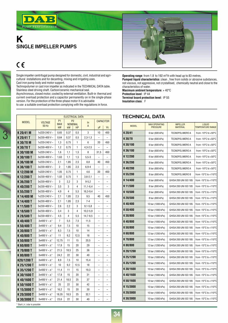
®
34
3MODEL
K 20/41 MK 20/41 TK 30/70 MK 30/70 TK 30/100 MK 30/100 TK 36/100 MK 36/100 TK 12/200 MK 12/200 TK 36/200 TK 40/200 TK 55/200 TK 14/400 MK 14/400 TK 11/500 TK 18/500 TK 28/500 TK 40/400 TK 50/400 TK 30/800 TK 40/800 TK 50/800 TK 60/800 TK 70/800 TK 80/800 TK20/1200 TK 25/1200 TK 35/1200 TK 30/1600 TK 40/1600 TK 50/1600 TK 15/3000 TK 20/3000 TK 30/3000 T
VOLTAGE50 Hz
P1MAXkW
InA
1x220-240 V ~
3x230-400 V ~
1x220-240 V ~
3x230-400 V ~
1x220-240 V ~
3x230-400 V ~
1x220-240 V ~
3x230-400 V ~
1x220-240 V ~
3x230-400 V ~
3x230-400 V ~
3x230-400 V ~
3x230-400 V ~
1x220-240 V ~
3x230-400 V ~
3x230-400 V ~
3x230-400 V ~
3x230-400 V ~
3x400 V ~ ∆*
3x400 V ~ ∆*
3x400 V ~ ∆*
3x400 V ~ ∆*
3x400 V ~ ∆*
3x400 V ~ ∆*
3x400 V ~ ∆*
3x400 V ~ ∆*
3x400 V ~ ∆*
3x400 V ~ ∆*
3x400 V ~ ∆*
3x400 V ~ ∆*
3x400 V ~ ∆*
3x400 V ~ ∆*
3x400 V ~ ∆*
3x400 V ~ ∆*
3x400 V ~ ∆*
0,65
0,64
1,3
1,2
1,6
1,63
2,1
2
1,05
1,02
3
3,5
4,9
2,1
2,1
2,6
3,4
4,5
7
9,4
8,3
11
12,75
17,8
21,5
24,2
8,9
10
11,4
17,8
21,4
25
16,2
18,35
23,6
0,37
0,37
0,75
0,75
1,1
1,1
1,85
1,85
0,75
0,75
2,2
3
4
1,85
1,85
2,2
3
4
5,5
7,5
7,5
9,2
11
15
18,5
22
7,5
9,2
11
15
18,5
22
15
18,5
22
0,5
0,5
1
1
1,5
1,5
2,5
2,5
1
1
3
4
5,5
2,5
2,5
3
4
5,5
7,5
10
10
12,5
15
20
25
30
10
12,5
15
20
25
30
20
25
30
10
–
20
–
31,5
–
40
–
20
–
–
–
–
40
–
–
–
–
–
–
–
–
–
–
–
–
–
–
–
–
–
–
–
–
–
450
–
450
–
450
–
450
–
450
–
–
–
–
450
–
–
–
–
–
–
–
–
–
–
–
–
–
–
–
–
–
–
–
–
–
3
2,3-1,3
6
4,3-2,5
8
5,5-3
8,8
6,9-4
4,6
3,6-2,1
9-5,2
11,1-6,4
16,3-9,4
9,5
7-4
9,1-5,8
10,2-5,9
14,7-8,5
11,5
15
14
18
20,5
29
36
40
15,4
18
19,3
31
37
42
30
32,1
40
ELECTRICAL DATA
P2NOMINALkW HP
CAPACITOR
µF Vc
KSINGLE IMPELLER PUMPS
TECHNICAL DATA
Single impeller centrifugal pump designed for domestic, civil, industrial and agri-cultural installations and for decanting, mixing and irrigating uses.Cast iron pump body and motor support.Technopolymer or cast iron impeller as indicated in the TECHNICAL DATA table.Stainless steel driving shaft. Carbon/ceramic mechanical seal.Asynchronous, closed motor, cooled by external ventilation. Built-in thermal andcurrent overload protection and a capacitor permanently on in the single-phaseversion. For the protection of the three-phase motor it is advisableto use a suitable overload protection complying with the regulations in force.
Operating range: from 1.8 to 192 m3/h with head up to 83 metres.Pumped liquid characteristics :clean , free from solids or abrasive substances,not viscous, not aggressive, not crystallised, chemically neutral and close to thecharacteristics of water.Maximum ambient temperature: + 40°CProtection level : IP 44Terminal board protection level: IP 55 Insulation class : F
K 20/41
K 30/70
K 30/100
K 36/100
K 12/200
K 36/200
K 40/200
K 55/200
K 14/400
K 11/500
K 18/500
K 28/500
K 40/400
K 50/400
K 30/800
K 40/800
K 50/800
K 60/800
K 70/800
K 80/800
K 20/1200
K 25/1200
K 35/1200
K 30/1600
K 40/1600
K 50/1600
K 15/3000
K 20/3000
K 30/3000
6 bar (600 kPa)
6 bar (600 kPa)
6 bar (600 kPa)
6 bar (600 kPa)
6 bar (600 kPa)
8 bar (800 kPa)
8 bar (800 kPa)
8 bar (800 kPa)
6 bar (600 kPa)
8 bar (800 kPa)
8 bar (800 kPa)
8 bar (800 kPa)
10 bar (1000 kPa)
10 bar (1000 kPa)
10 bar (1000 kPa)
10 bar (1000 kPa)
10 bar (1000 kPa)
12 bar (1200 kPa)
12 bar (1200 kPa)
12 bar (1200 kPa)
10 bar (1000 kPa)
10 bar (1000 kPa)
10 bar (1000 kPa)
10 bar (1000 kPa)
10 bar (1000 kPa)
10 bar (1000 kPa)
10 bar (1000 kPa)
10 bar (1000 kPa)
10 bar (1000 kPa)
TECNOPOLIMERO A
TECNOPOLIMERO A
TECNOPOLIMERO A
TECNOPOLIMERO A
TECNOPOLIMERO A
TECNOPOLIMERO A
TECNOPOLIMERO A
TECNOPOLIMERO B
GHISA 200 UNI ISO 185
GHISA 200 UNI ISO 185
GHISA 200 UNI ISO 185
GHISA 200 UNI ISO 185
GHISA 200 UNI ISO 185
GHISA 200 UNI ISO 185
GHISA 200 UNI ISO 185
GHISA 200 UNI ISO 185
GHISA 200 UNI ISO 185
GHISA 200 UNI ISO 185
GHISA 200 UNI ISO 185
GHISA 200 UNI ISO 185
GHISA 200 UNI ISO 185
GHISA 200 UNI ISO 185
GHISA 200 UNI ISO 185
GHISA 200 UNI ISO 185
GHISA 200 UNI ISO 185
GHISA 200 UNI ISO 185
GHISA 200 UNI ISO 185
GHISA 200 UNI ISO 185
GHISA 200 UNI ISO 185
from -10°C to +50°C
from -10°C to +50°C
from -10°C to +50°C
from -10°C to +50°C
from -10°C to +50°C
from -10°C to +50°C
from -10°C to +50°C
from -15°C to +110°C
from -15°C to +110°C
from -15°C to +110°C
from -15°C to +110°C
from -15°C to +110°C
from -15°C to +110°C
from -15°C to +110°C
from -15°C to +110°C
from -15°C to +110°C
from -15°C to +110°C
from -15°C to +110°C
from -15°C to +110°C
from -15°C to +110°C
from -15°C to +110°C
from -15°C to +110°C
from -15°C to +110°C
from -15°C to +110°C
from -15°C to +110°C
from -15°C to +110°C
from -15°C to +110°C
from -15°C to +110°C
from -15°C to +110°C
MODELMAX OPERATING IMPELLER LIQUID
PRESSURE MATERIAL TEMPERATURE RANGE
* Start ( ) star is possible Y
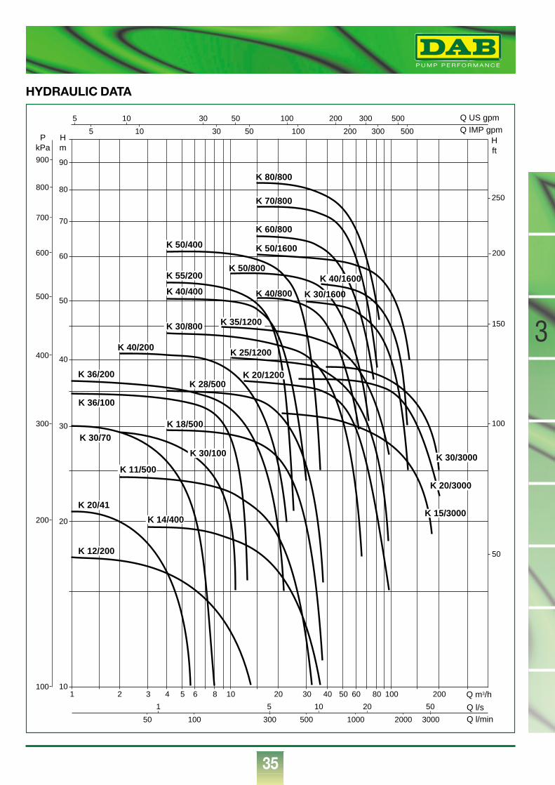
®
35
3
HYDRAULIC DATA
1 2 3 4 5 6 8 10 20 30 40 50 60 80 100 200 Q m3/h
Q l/sQ l/min50
1 5 10 20 50
100 300 500 1000 2000 3000
10
20
30
40
50
60
70
80
90
Q IMP gpmQ US gpm
Hm
Hft
PkPa
5
5
100
200
300
400
500
600
700
800
900
50
100
150
200
250
10 30 50 100 200 300 500
10 30 50 100 200 300 500
K 20/41
K 12/200
K 14/400
K 18/500
K 28/500
K 11/500
K 30/70
K 36/100
K 36/200
K 40/200
K 30/800
K 55/200
K 50/400
K 40/400 K 40/800
K 50/800
K 60/800
K 50/1600
K 70/800
K 80/800
K 30/100
K 20/1200
K 25/1200
K 35/1200
K 30/1600
K 40/1600
K 15/3000
K 20/3000
K 30/3000
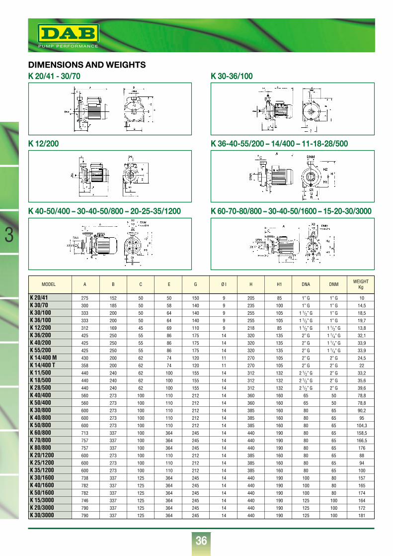
®
36
3
K 20/41 275 152 50 50 150 9 205 85 1” G 1” G 10
K 30/70 300 185 50 58 140 9 235 100 1” G 1” G 14,5
K 30/100 333 200 50 64 140 9 255 105 1 1/2” G 1” G 18,5
K 36/100 333 200 50 64 140 9 255 105 1 1/2” G 1” G 19,7
K 12/200 312 169 45 69 110 9 218 85 1 1/2” G 1 1/2” G 13,8
K 36/200 425 250 55 86 175 14 320 135 2” G 1 1/4” G 32,1
K 40/200 425 250 55 86 175 14 320 135 2” G 1 1/4” G 33,9
K 55/200 425 250 55 86 175 14 320 135 2” G 1 1/4” G 33,9
K 14/400 M 430 200 62 74 120 11 270 105 2” G 2” G 24,5
K 14/400 T 358 200 62 74 120 11 270 105 2” G 2” G 22
K 11/500 440 240 62 100 155 14 312 132 2 1/2” G 2” G 33,2
K 18/500 440 240 62 100 155 14 312 132 2 1/2” G 2” G 35,6
K 28/500 440 240 62 100 155 14 312 132 2 1/2” G 2” G 39,6
K 40/400 560 273 100 110 212 14 360 160 65 50 78,8
K 50/400 560 273 100 110 212 14 360 160 65 50 78,8
K 30/800 600 273 100 110 212 14 385 160 80 65 90,2
K 40/800 600 273 100 110 212 14 385 160 80 65 95
K 50/800 600 273 100 110 212 14 385 160 80 65 104,3
K 60/800 713 337 100 364 245 14 440 190 80 65 158,5
K 70/800 757 337 100 364 245 14 440 190 80 65 166,5
K 80/800 757 337 100 364 245 14 440 190 80 65 176
K 20/1200 600 273 100 110 212 14 385 160 80 65 88
K 25/1200 600 273 100 110 212 14 385 160 80 65 94
K 35/1200 600 273 100 110 212 14 385 160 80 65 100
K 30/1600 738 337 125 364 245 14 440 190 100 80 157
K 40/1600 782 337 125 364 245 14 440 190 100 80 165
K 50/1600 782 337 125 364 245 14 440 190 100 80 174
K 15/3000 746 337 125 364 245 14 440 190 125 100 164
K 20/3000 790 337 125 364 245 14 440 190 125 100 172
K 30/3000 790 337 125 364 245 14 440 190 125 100 181
MODEL A B C E G Ø I H H1 DNA DNM WEIGHTKg
DIMENSIONS AND WEIGHTSK 20/41 - 30/70
K 12/200
K 40-50/400 – 30-40-50/800 – 20-25-35/1200 K 60-70-80/800 – 30-40-50/1600 – 15-20-30/3000
K 30-36/100
K 36-40-55/200 – 14/400 – 11-18-28/500
E
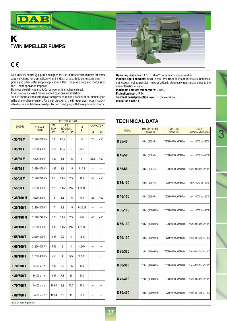
®
37
3
KTWIN IMPELLER PUMPS
Twin impeller centrifugal pump designed for use in pressurisation units for watersupply systems for domestic, civil and industrial use. Suitable for sprinkling irri-gation and other water supply applications. Cast iron pump body and motor sup-port. Technopolymer impeller.Stainless steel driving shaft. Carbon/ceramic mechanical seal.Asynchronous, closed motor, cooled by external ventilation.Built-in thermal and current overload protection and a capacitor permanently onin the single-phase version. For the protection of the three-phase motor it is advi-sable to use a suitable overload protection complying with the regulations in force.
Operating range: from 1.5 to 30 m3/h with head up to 97 metres.Pumped liquid characteristics :clean , free from solids or abrasive substances,not viscous, not aggressive, not crystallised, chemically neutral and close to thecharacteristics of water.Maximum ambient temperature: + 40°CProtection level : IP 44Terminal board protection level: IP 55 over 4 kWInsulation class : F
MODEL
K 35/40 M
K 35/40 T
K 45/50 M
K 45/50 T
K 55/50 M
K 55/50 T
K 35/100 M
K 35/100 T
K 40/100 M
K 40/100 T
K 55/100 T
K 66/100 T
K 90/100 T
K 70/300 T
K 80/300 T
K 70/400 T
K 80/400 T
VOLTAGE50 Hz
P1MAXkW
InA
1x220-240 V ~
3x230-400 V ~
1x220-240 V ~
3x230-400 V ~
1x220-240 V ~
3x230-400 V ~
1x220-240 V ~
3x230-400 V ~
1x220-240 V ~
3x230-400 V ~
3x230-400 V ~
3x230-400 V ~
3x230-400 V ~
3x400 V ~ ∆*
3x400 V ~ ∆*
3x400 V ~ ∆*
3x400 V ~ ∆*
1,2
1,17
1,99
1,96
2,7
2,73
1,6
1,7
1,9
2,0
3,87
4,68
5,53
7,42
9,57
10,66
12,34
0,75
0,75
1,1
1,1
1,85
1,85
1,1
1,1
1,85
1,85
2,2
3
4
5,5
7,5
9,2
11
1
1
1,5
1,5
2,5
2,5
1,5
1,5
2,5
2,5
3
4
5,5
7,5
10
12,5
15
20
–
31,5
–
40
–
25
–
40
–
–
–
–
–
–
–
–
450
–
450
–
450
–
450
–
450
–
–
–
–
–
–
–
–
5,4
4-2,3
9
6,3-3,6
12,8
8,31-4,8
7,69
5,42-3,13
9,03
6,23-3,6
11,6-6,7
14,6-8,4
16,8-9,7
12,3
17,3
17,8
20,6
ELECTRICAL DATA
P2NOMINALkW HP
CAPACITOR
µF Vc
K 35/40
K 45/50
K 55/50
K 35/100
K 40/100
K 55/100
K 66/100
K 90/100
K 70/300
K 80/300
K 70/400
K 80/400
6 bar (600 kPa)
8 bar (800 kPa)
8 bar (800 kPa)
6 bar (600 kPa)
6 bar (600 kPa)
10 bar (1000 kPa)
10 bar (1000 kPa)
12 bar (1200 kPa)
12 bar (1200 kPa)
12 bar (1200 kPa)
12 bar (1200 kPa)
12 bar (1200 kPa)
TECHNOPOLYMER A
TECHNOPOLYMER A
TECHNOPOLYMER B
TECHNOPOLYMER A
TECHNOPOLYMER A
TECHNOPOLYMER A
TECHNOPOLYMER B
TECHNOPOLYMER B
TECHNOPOLYMER B
TECHNOPOLYMER B
TECHNOPOLYMER B
TECHNOPOLYMER B
from -10°C to +50°C
from -10°C to +50°C
from -15°C to +110°C
from -10°C to +50°C
from -10°C to +50°C
from -10°C to +50°C
from -15°C to +110°C
from -15°C to +110°C
from -15°C to +110°C
from -15°C to +110°C
from -15°C to +110°C
from -15°C to +110°C
MODELMAX OPERATING IMPELLER LIQUID
PRESSURE MATERIAL TEMPERATURE RANGE
TECHNICAL DATA
* Start ( ) star is possibleY
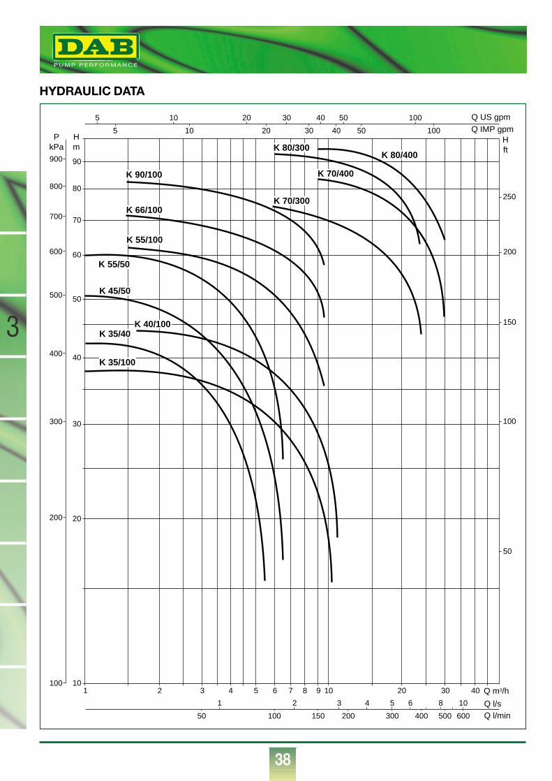
1 4 403020109876532 Q m3/h
Q l/sQ l/min
1
100 150 200 300 400 500 60050
10
20
30
40
50
60
70
80
90
Q IMP gpmQ US gpm
Hm
Hft
PkPa
5
5
100
200
300
400
500
600
700
800
900
50
100
150
200
250
10 20 30 40 50 100
10 20 30 40 50 100
2 3 4 5 6 8 10
K 35/40K 40/100
K 35/100
K 45/50
K 55/50
K 55/100
K 66/100K 70/300
K 70/400
K 80/400K 80/300
K 90/100
®
38
3
HYDRAULIC DATA
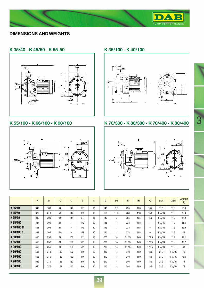
®
39
3
K 35/40 342 180 76 148 72 15 148 9,5 235 100 135 1” G 1” G 15,9
K 45/50 370 210 75 144 69 15 165 11,5 268 118 150 1 1/4” G 1” G 23,3
K 55/50 333 200 50 114 64 15 140 9 255 105 150 1 1/4” G 1” G 27,2
K 35/100 387 205 88 – 179 20 145 11 233 108 – 1 1/2” G 1” G 21,5
K 40/100 M 461 205 88 – 179 20 145 11 233 108 – 1 1/2” G 1” G 25,9
K 40/100 T 387 205 88 – 179 20 145 11 233 108 – 1 1/2” G 1” G 22
K 50/100 450 256 88 160 72 18 200 14 312,5 140 172,5 1 1/2” G 1” G 37,1
K 66/100 450 256 88 160 72 18 200 14 312,5 140 172,5 1 1/2” G 1” G 39,7
K 90/100 450 256 88 160 72 18 200 14 312,5 140 172,5 1 1/2” G 1” G 43
K 70/300 595 270 122 182 60 20 210 14 340 160 180 2” G 1 1/4” G 72
K 80/300 595 270 122 182 60 20 210 14 340 160 180 2” G 1 1/4” G 78,5
K 70/400 635 270 122 182 60 20 210 14 340 160 180 2” G 1 1/4” G 74
K 80/400 635 270 122 182 60 20 210 14 340 160 180 2” G 1 1/4” G 78
A B C D E F G Ø I H H1 H2 DNA DNM WEIGHTKg
DIMENSIONS AND WEIGHTS
K 35/40 - K 45/50 - K 55-50 K 35/100 - K 40/100
K 55/100 - K 66/100 - K 90/100 K 70/300 - K 80/300 - K 70/400 - K 80/400
H H
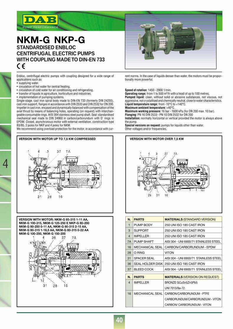
®
40
4
NKM-G NKP-GSTANDARDISED ENBLOCCENTRIFUGAL ELECTRIC PUMPSWITH COUPLING MADE TO DIN-EN 733
Enbloc, centrifugal electric pumps with coupling designed for a wide range ofapplications such as:• supplying water.• circulation of hot water for central heating.• circulation of cold water for air conditioning and refrigerating.• transfer of liquids in agriculture, horticulture and industries.• implementation of pumping systems.Single-stage, cast iron spiral body made to DIN-EN 733 (formerly DIN 24255),cast iron support, flanges in accordance with DIN 2533 and DIN 2532 for DN 200.Impeller in cast iron, encased and dynamically balanced with compensation of theaxial thrust by means of balancing holes, operating (on request) with interchan-geable consumable rings. AISI 304 stainless steel pump shaft. Seal: standardisedmechanical seal made to DIN 24960 in carbon/carborundum with O’ rings inEPDM. Closed, asynchronous motor with external ventilation, construction typeB3/B5, 2 poles for NKP and 4 poles for NKM.We recommend using overload protection for the motor, in accordance with cur-
rent norms. In the case of liquids denser than water, the motors must be propor-tionally more powerful.
Speed of rotation: 1450 - 2900 1/min.Operating range: from 1 to 500 m3/h with a head of up to 100 metres.Pumped liquid: clean, without solid or abrasive substances, not viscous, notaggressive, not crystallised and chemically neutral, close to water characteristics.Liquid temperature range: from -10°C to +140°C.Maximum ambient temperature: +40°C.Maximum working pressure: 16 bar - 1600 kPa (for DN 200 max. 10 bar).Flanging: PN 16 DIN 2533 - PN 10 DIN 2532 for DN 200Installation: normally horizontal or vertical provided the motor is always abovethe pump.Special versions on request: pumps for liquids other than water.Other voltages and/or frequencies.
VERSION WITH MOTOR UP TO 7,5 KW COMPRESSED
VERSION WITH MOTOR: NKM-G 65-315 1-11 AA,NKM-G 100-315, NKM-G 125-250 E NKP-G 80-200NKM-G 80-250 0-11 AA, NKM-G 80-315 2-15 AA, NKM-G 80-315 1-18,5 AA, NKM-G 80-315 0-22 AANKM-G 100-250, NKM-G 150-200
VERSION WITH MOTOR OVER 7,5 KW
N.
1
3
4
7A
16
28
31
36
37
PARTS
PUMP BODY
SUPPORT
IMPELLER
PUMP SHAFT
MECHANICAL SEAL
O RING
SPACER SEAL
SEAL HOLDER DISK
BLEED COCK
MATERIALS (STANDARD VERSION)
250 UNI ISO 185 CAST IRON
250 UNI ISO 185 CAST IRON
250 UNI ISO 185 CAST IRON
AISI 304 - UNI 6900/71 STAINLESS STEEL
CARBON/CARBORUNDUM - EPDM
VITON
AISI 304 - UNI 6900/71 STAINLESS STEEL
250 UNI ISO 185 CAST IRON
AISI 304 - UNI 6900/71 STAINLESS STEEL
N.
4
16
PARTS
IMPELLER
MECHANICAL SEAL
MATERIALS (VERSION ON REQUEST)
BRONZE GCuSn5Zn5Pb5
UNI 7013/8a-72
CARBON/CARBORUNDUM - PTFE
CARBORUNDUM/CARBORUNDUM - VITON
CARBON/ CARBORUNDUM - VITON
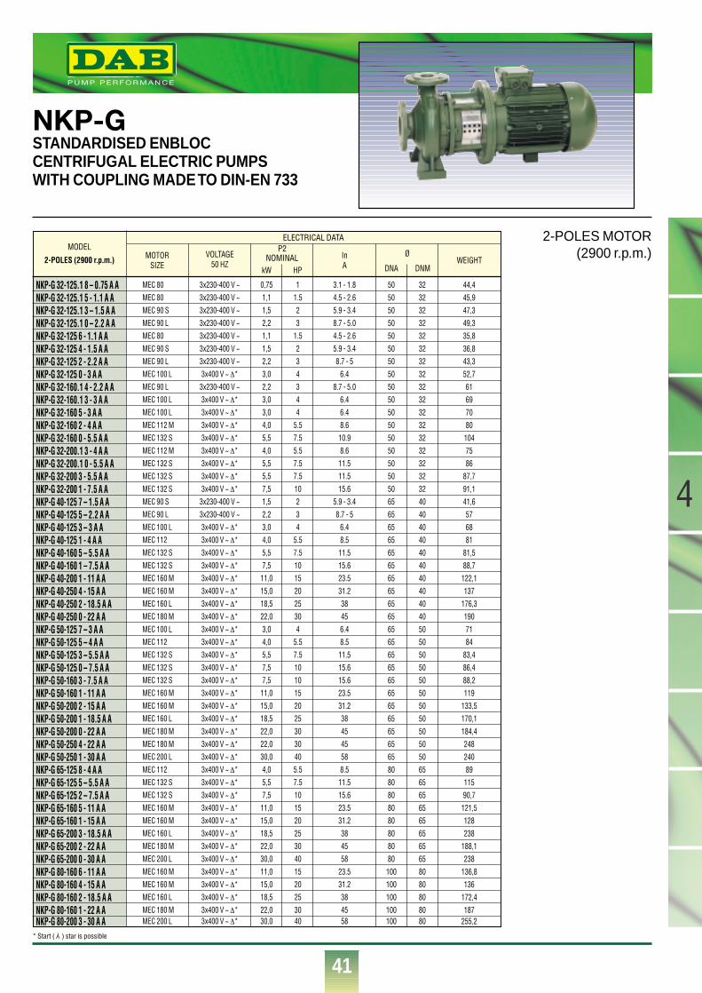
®
41
4
NKP-GSTANDARDISED ENBLOCCENTRIFUGAL ELECTRIC PUMPSWITH COUPLING MADE TO DIN-EN 733
MODEL
2-POLES (2900 r.p.m.)
NKP-G 32-125.1 8 – 0.75 A ANKP-G 32-125.1 5 - 1.1 A ANKP-G 32-125.1 3 – 1.5 A ANKP-G 32-125.1 0 – 2.2 A ANKP-G 32-125 6 - 1.1 A ANKP-G 32-125 4 - 1.5 A ANKP-G 32-125 2 - 2.2 A ANKP-G 32-125 0 - 3 A ANKP-G 32-160.1 4 - 2.2 A ANKP-G 32-160.1 3 - 3 A ANKP-G 32-160 5 - 3 A ANKP-G 32-160 2 - 4 A ANKP-G 32-160 0 - 5.5 A ANKP-G 32-200.1 3 - 4 A ANKP-G 32-200.1 0 - 5.5 A ANKP-G 32-200 3 - 5.5 A ANKP-G 32-200 1 - 7.5 A ANKP-G 40-125 7 – 1.5 A ANKP-G 40-125 5 – 2.2 A ANKP-G 40-125 3 – 3 A ANKP-G 40-125 1 - 4 A ANKP-G 40-160 5 – 5.5 A ANKP-G 40-160 1 – 7.5 A ANKP-G 40-200 1 - 11 A ANKP-G 40-250 4 - 15 A ANKP-G 40-250 2 - 18.5 A ANKP-G 40-250 0 - 22 A ANKP-G 50-125 7 – 3 A ANKP-G 50-125 5 – 4 A ANKP-G 50-125 3 – 5.5 A ANKP-G 50-125 0 – 7.5 A ANKP-G 50-160 3 - 7.5 A ANKP-G 50-160 1 - 11 A ANKP-G 50-200 2 - 15 A ANKP-G 50-200 1 - 18.5 A ANKP-G 50-200 0 - 22 A ANKP-G 50-250 4 - 22 A ANKP-G 50-250 1 - 30 A ANKP-G 65-125 8 - 4 A ANKP-G 65-125 5 – 5.5 A ANKP-G 65-125 2 – 7.5 A ANKP-G 65-160 5 - 11 A ANKP-G 65-160 1 - 15 A ANKP-G 65-200 3 - 18.5 A ANKP-G 65-200 2 - 22 A ANKP-G 65-200 0 - 30 A ANKP-G 80-160 6 - 11 A ANKP-G 80-160 4 - 15 A ANKP-G 80-160 2 - 18.5 A ANKP-G 80-160 1 - 22 A ANKP-G 80-200 3 - 30 A A
VOLTAGE50 HZ
MOTORSIZE
P2NOMINAL In
A DNAkW HP DNM
ØWEIGHT
MEC 80MEC 80 MEC 90 SMEC 90 LMEC 80MEC 90 S MEC 90 LMEC 100 LMEC 90 LMEC 100 LMEC 100 LMEC 112 M MEC 132 SMEC 112 M MEC 132 SMEC 132 SMEC 132 SMEC 90 S MEC 90 LMEC 100 LMEC 112MEC 132 SMEC 132 SMEC 160 MMEC 160 MMEC 160 LMEC 180 MMEC 100 LMEC 112MEC 132 SMEC 132 SMEC 132 SMEC 160 MMEC 160 MMEC 160 LMEC 180 MMEC 180 MMEC 200 LMEC 112MEC 132 SMEC 132 SMEC 160 MMEC 160 MMEC 160 LMEC 180 MMEC 200 LMEC 160 MMEC 160 MMEC 160 LMEC 180 MMEC 200 L
3x230-400 V ~3x230-400 V ~3x230-400 V ~3x230-400 V ~3x230-400 V ~3x230-400 V ~3x230-400 V ~3x400 V ~ ∆*
3x230-400 V ~3x400 V ~ ∆*3x400 V ~ ∆*3x400 V ~ ∆*3x400 V ~ ∆*3x400 V ~ ∆*3x400 V ~ ∆*3x400 V ~ ∆*3x400 V ~ ∆*
3x230-400 V ~3x230-400 V ~3x400 V ~ ∆*3x400 V ~ ∆*3x400 V ~ ∆*3x400 V ~ ∆*3x400 V ~ ∆*3x400 V ~ ∆*3x400 V ~ ∆*3x400 V ~ ∆*3x400 V ~ ∆*3x400 V ~ ∆*3x400 V ~ ∆*3x400 V ~ ∆*3x400 V ~ ∆*3x400 V ~ ∆*3x400 V ~ ∆*3x400 V ~ ∆*3x400 V ~ ∆*3x400 V ~ ∆*3x400 V ~ ∆*3x400 V ~ ∆*3x400 V ~ ∆*3x400 V ~ ∆*3x400 V ~ ∆*3x400 V ~ ∆*3x400 V ~ ∆*3x400 V ~ ∆*3x400 V ~ ∆*3x400 V ~ ∆*3x400 V ~ ∆*3x400 V ~ ∆*3x400 V ~ ∆*3x400 V ~ ∆*
0,751,11,52,21,11,52,23,02,23,03,04,05,54,05,55,57,51,52,23,04,05,57,5
11,015,018,522,03,04,05,57,57,5
11,015,018,522,022,030,04,05,57,5
11,015,018,522,030,011,015,018,522,030,0
11.523
1.5234344
5.57.55.57.57.510234
5.57.510152025304
5.57.510101520253030405.57.51015202530401520253040
3.1 - 1.84.5 - 2.65.9 - 3.48.7 - 5.04.5 - 2.65.9 - 3.48.7 - 5
6.48.7 - 5.0
6.46.48.610.98.611.511.515.6
5.9 - 3.48.7 - 5
6.48.511.515.623.531.238456.48.511.515.615.623.531.2384545588.511.515.623.531.2384558
23.531.2384558
50505050505050505050505050505050506565656565656565656565656565656565656565658080808080808080100100100100100
323232323232323232323232323232323240404040404040404040505050505050505050505065656565656565658080808080
44,445,947,349,335,836,843,352,7616970801047586
87,791,141,6576881
81,588,7
122,1137
176,31907184
83,486,488,2119
133,5170,1184,42482408911590,7
121,5128238
188,1238
136,8136
172,4187
255,2
ELECTRICAL DATA
* Start ( ) star is possible Y
2-POLES MOTOR(2900 r.p.m.)
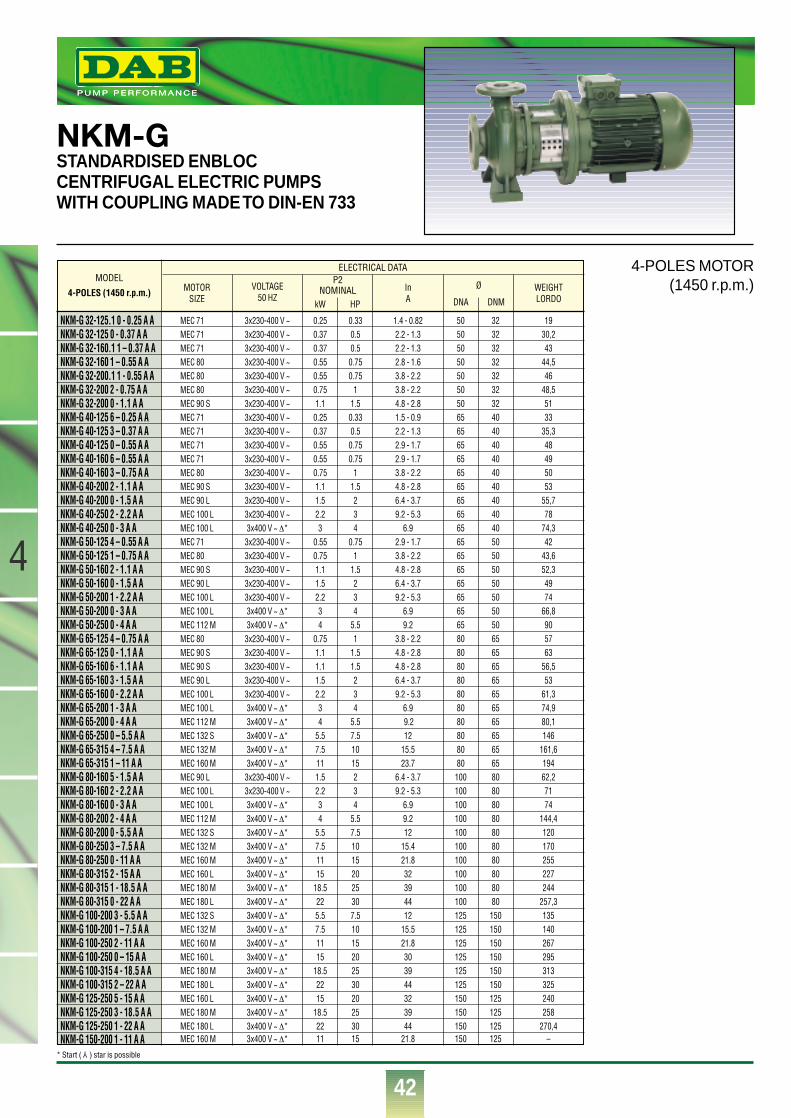
®
42
4
®
NKM-GSTANDARDISED ENBLOCCENTRIFUGAL ELECTRIC PUMPSWITH COUPLING MADE TO DIN-EN 733
MODEL
4-POLES (1450 r.p.m.)
NKM-G 32-125.1 0 - 0.25 A ANKM-G 32-125 0 - 0.37 A ANKM-G 32-160.1 1 – 0.37 A ANKM-G 32-160 1 – 0.55 A ANKM-G 32-200.1 1 - 0.55 A ANKM-G 32-200 2 - 0.75 A ANKM-G 32-200 0 - 1.1 A ANKM-G 40-125 6 – 0.25 A ANKM-G 40-125 3 – 0.37 A ANKM-G 40-125 0 – 0.55 A ANKM-G 40-160 6 – 0.55 A ANKM-G 40-160 3 – 0.75 A ANKM-G 40-200 2 - 1.1 A ANKM-G 40-200 0 - 1.5 A ANKM-G 40-250 2 - 2.2 A ANKM-G 40-250 0 - 3 A ANKM-G 50-125 4 – 0.55 A ANKM-G 50-125 1 – 0.75 A ANKM-G 50-160 2 - 1.1 A ANKM-G 50-160 0 - 1.5 A ANKM-G 50-200 1 - 2.2 A ANKM-G 50-200 0 - 3 A ANKM-G 50-250 0 - 4 A ANKM-G 65-125 4 – 0.75 A ANKM-G 65-125 0 - 1.1 A ANKM-G 65-160 6 - 1.1 A ANKM-G 65-160 3 - 1.5 A ANKM-G 65-160 0 - 2.2 A ANKM-G 65-200 1 - 3 A ANKM-G 65-200 0 - 4 A ANKM-G 65-250 0 – 5.5 A ANKM-G 65-315 4 – 7.5 A ANKM-G 65-315 1 – 11 A ANKM-G 80-160 5 - 1.5 A ANKM-G 80-160 2 - 2.2 A ANKM-G 80-160 0 - 3 A ANKM-G 80-200 2 - 4 A ANKM-G 80-200 0 - 5.5 A ANKM-G 80-250 3 – 7.5 A ANKM-G 80-250 0 - 11 A ANKM-G 80-315 2 - 15 A ANKM-G 80-315 1 - 18.5 A ANKM-G 80-315 0 - 22 A ANKM-G 100-200 3 - 5.5 A ANKM-G 100-200 1 – 7.5 A ANKM-G 100-250 2 - 11 A ANKM-G 100-250 0 – 15 A ANKM-G 100-315 4 - 18.5 A ANKM-G 100-315 2 – 22 A ANKM-G 125-250 5 - 15 A ANKM-G 125-250 3 - 18.5 A ANKM-G 125-250 1 - 22 A ANKM-G 150-200 1 - 11 A A
VOLTAGE50 HZ
MOTORSIZE
P2NOMINAL In
A DNAkW HP DNM
Ø WEIGHTLORDO
MEC 71MEC 71MEC 71MEC 80MEC 80MEC 80MEC 90 SMEC 71MEC 71MEC 71MEC 71MEC 80MEC 90 SMEC 90 LMEC 100 LMEC 100 LMEC 71MEC 80MEC 90 SMEC 90 LMEC 100 LMEC 100 LMEC 112 MMEC 80MEC 90 SMEC 90 SMEC 90 LMEC 100 LMEC 100 LMEC 112 MMEC 132 SMEC 132 MMEC 160 M MEC 90 LMEC 100 LMEC 100 LMEC 112 MMEC 132 SMEC 132 MMEC 160 MMEC 160 LMEC 180 MMEC 180 LMEC 132 SMEC 132 MMEC 160 MMEC 160 LMEC 180 MMEC 180 LMEC 160 LMEC 180 MMEC 180 LMEC 160 M
3x230-400 V ~3x230-400 V ~3x230-400 V ~3x230-400 V ~3x230-400 V ~3x230-400 V ~3x230-400 V ~3x230-400 V ~3x230-400 V ~3x230-400 V ~3x230-400 V ~3x230-400 V ~3x230-400 V ~3x230-400 V ~3x230-400 V ~3x400 V ~ ∆*
3x230-400 V ~3x230-400 V ~3x230-400 V ~3x230-400 V ~3x230-400 V ~3x400 V ~ ∆*3x400 V ~ ∆*
3x230-400 V ~3x230-400 V ~3x230-400 V ~3x230-400 V ~3x230-400 V ~3x400 V ~ ∆*3x400 V ~ ∆*3x400 V ~ ∆*3x400 V ~ ∆*3x400 V ~ ∆*
3x230-400 V ~3x230-400 V ~3x400 V ~ ∆*3x400 V ~ ∆*3x400 V ~ ∆*3x400 V ~ ∆*3x400 V ~ ∆*3x400 V ~ ∆*3x400 V ~ ∆*3x400 V ~ ∆*3x400 V ~ ∆*3x400 V ~ ∆*3x400 V ~ ∆*3x400 V ~ ∆*3x400 V ~ ∆*3x400 V ~ ∆*3x400 V ~ ∆*3x400 V ~ ∆*3x400 V ~ ∆*3x400 V ~ ∆*
0.250.370.370.550.550.751.1
0.250.370.550.550.751.11.52.23
0.550.751.11.52.234
0.751.11.11.52.234
5.57.5111.52.234
5.57.51115
18.5225.57.51115
18.52215
18.52211
0.330.50.5
0.750.75
11.5
0.330.5
0.750.75
11.5234
0.751
1.5234
5.51
1.51.5234
5.57.51015234
5.57.510152025307.5101520253020253015
1.4 - 0.822.2 - 1.32.2 - 1.32.8 - 1.63.8 - 2.23.8 - 2.24.8 - 2.81.5 - 0.92.2 - 1.32.9 - 1.72.9 - 1.73.8 - 2.24.8 - 2.86.4 - 3.79.2 - 5.3
6.92.9 - 1.73.8 - 2.24.8 - 2.86.4 - 3.79.2 - 5.3
6.99.2
3.8 - 2.24.8 - 2.84.8 - 2.86.4 - 3.79.2 - 5.3
6.99.212
15.523.7
6.4 - 3.79.2 - 5.3
6.99.212
15.421.832394412
15.521.8303944323944
21.8
505050505050506565656565656565656565656565656580808080808080808080
100100100100100100100100100100125125125125125125150150150150
32323232323232404040404040404040505050505050506565656565656565656580808080808080808080
150150150150150150125125125125
1930,243
44,546
48,55133
35,348495053
55,778
74,342
43,652,34974
66,8905763
56,553
61,374,980,1146
161,619462,27174
144,4120170255227244
257,3135140267295313325240258
270,4–
ELECTRICAL DATA
* Start ( ) star is possible Y
4-POLES MOTOR(1450 r.p.m.)
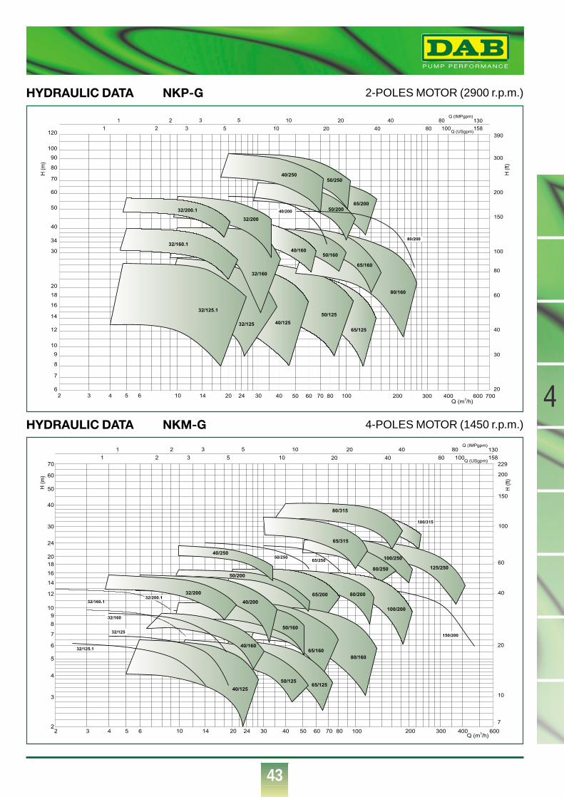
®
43
4
2-POLES MOTOR (2900 r.p.m.)HYDRAULIC DATA NKP-G
H (
ft)
20
30
40
80
60
100
150
200
300
390
130
1
1 2 3 5 10 20 40 80
2 3 5 10 20 40 80 100 158
Q (IMPgpm)
Q (USgpm)
2 6543 1410 2420 30 8070605040 200100 600400300 700
8
12
10
9
6
7
20
18
16
14
40
30
34
70
60
50
120
100
90
80
H (
m)
80/160
65/160
50/160
65/20050/200
50/25040/250
40/200
80/200
40/125
50/125
65/125
40/160
32/125.1
32/160
32/160.1
32/200
32/200.1
32/125
Q (m3/h)
4-POLES MOTOR (1450 r.p.m.)HYDRAULIC DATA NKM-G
H (
m)
Q (m3/h)
20
40
60
100
229
200
150
10
H (
ft)
130
1
1 2 3 5 10 20 40 80
2 3 5 10 20 40 80 100 158
Q (IMPgpm)
Q (USgpm)
7
65/315
80/200
50/250
65/200*07/97
125/250
80/315
80/20065/200
80/16065/160
50/160
50/200
40/200
32/200
65/250
65/315
50/125
32/125
65/12540/125
32/125.140/160
100/200
100/315
100/250
80/250
150/200
32/160.1
32/160
32/200.1
2 6543 24201410 100807060504030 400300200 6002
4
3
9
8
7
6
5
2018
16
14
12
10
40
30
24
50
70
60
40/250
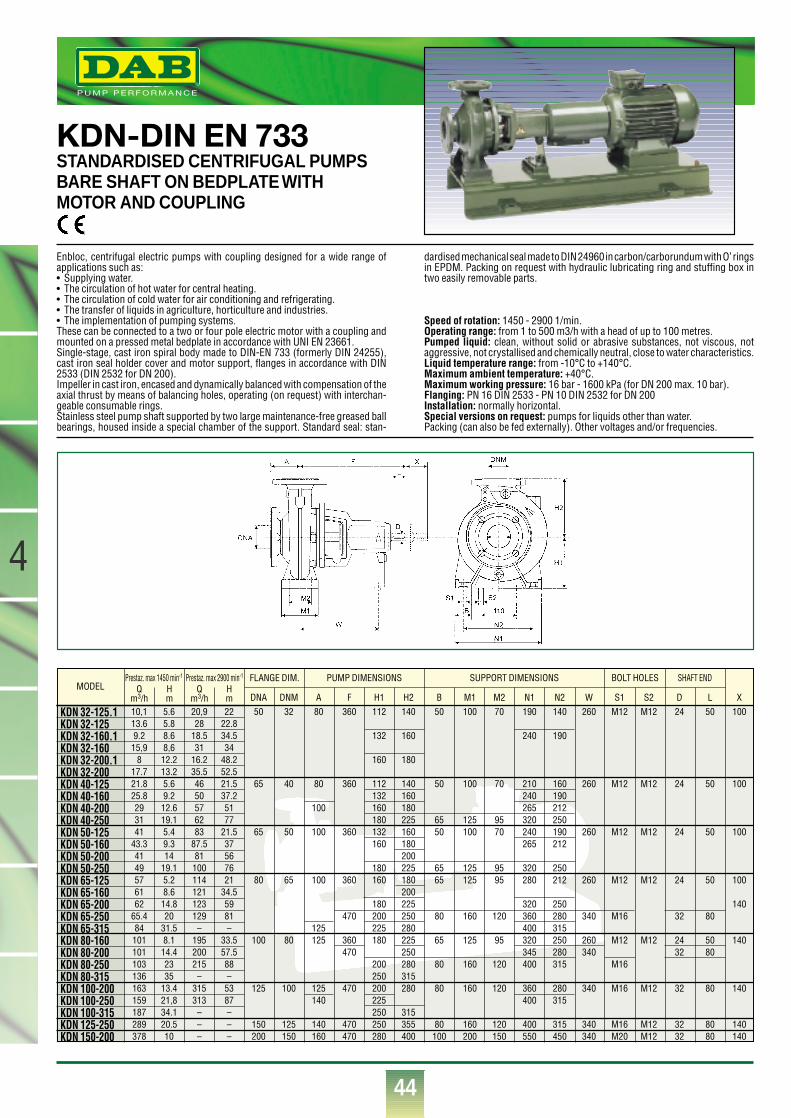
®
44
4
KDN-DIN EN 733STANDARDISED CENTRIFUGAL PUMPSBARE SHAFT ON BEDPLATE WITHMOTOR AND COUPLING
Enbloc, centrifugal electric pumps with coupling designed for a wide range ofapplications such as:• Supplying water.• The circulation of hot water for central heating.• The circulation of cold water for air conditioning and refrigerating.• The transfer of liquids in agriculture, horticulture and industries.• The implementation of pumping systems.These can be connected to a two or four pole electric motor with a coupling andmounted on a pressed metal bedplate in accordance with UNI EN 23661.Single-stage, cast iron spiral body made to DIN-EN 733 (formerly DIN 24255),cast iron seal holder cover and motor support, flanges in accordance with DIN2533 (DIN 2532 for DN 200).Impeller in cast iron, encased and dynamically balanced with compensation of theaxial thrust by means of balancing holes, operating (on request) with interchan-geable consumable rings.Stainless steel pump shaft supported by two large maintenance-free greased ballbearings, housed inside a special chamber of the support. Standard seal: stan-
dardised mechanical seal made to DIN 24960 in carbon/carborundum with O’ ringsin EPDM. Packing on request with hydraulic lubricating ring and stuffing box intwo easily removable parts.
Speed of rotation: 1450 - 2900 1/min.Operating range: from 1 to 500 m3/h with a head of up to 100 metres.Pumped liquid: clean, without solid or abrasive substances, not viscous, notaggressive, not crystallised and chemically neutral, close to water characteristics.Liquid temperature range: from -10°C to +140°C.Maximum ambient temperature: +40°C.Maximum working pressure: 16 bar - 1600 kPa (for DN 200 max. 10 bar).Flanging: PN 16 DIN 2533 - PN 10 DIN 2532 for DN 200Installation: normally horizontal.Special versions on request: pumps for liquids other than water.Packing (can also be fed externally). Other voltages and/or frequencies.
MODELFLANGE DIM.Prestaz. max 1450 min-1 Prestaz. max 2900 min-1
Qm3/h
Qm3/h
Hm
Hm
PUMP DIMENSIONS SUPPORT DIMENSIONS SHAFT ENDBOLT HOLES
KDN 32-125.1 KDN 32-125 KDN 32-160.1KDN 32-160 KDN 32-200.1KDN 32-200KDN 40-125 KDN 40-160 KDN 40-200KDN 40-250KDN 50-125 KDN 50-160 KDN 50-200KDN 50-250KDN 65-125 KDN 65-160KDN 65-200KDN 65-250KDN 65-315KDN 80-160KDN 80-200KDN 80-250 KDN 80-315 KDN 100-200 KDN 100-250 KDN 100-315 KDN 125-250KDN 150-200
10,113.69.215,9
817.721.825.8293141
43.34149576162
65.484101101103136163159187289378
5.65.88.68,612.213.25.69.212.619.15.49.314
19.15.28.614.820
31.58.114.42335
13.421,834.120.510
20,928
18.531
16.235.54650576283
87.581100114121123129–
195200215–
315313–––
2222.834.534
48.252.521.537.25177
21.537567621
34.55981–
33.557.588–5387–––
50 32 80 360 112 140 50 100 70 190 140 260 M12 M12 24 50 100
132 160 240 190
160 180
65 40 80 360 112 140 50 100 70 210 160 260 M12 M12 24 50 100132 160 240 190
100 160 180 265 212180 225 65 125 95 320 250
65 50 100 360 132 160 50 100 70 240 190 260 M12 M12 24 50 100160 180 265 212
200180 225 65 125 95 320 250
80 65 100 360 160 180 65 125 95 280 212 260 M12 M12 24 50 100200
180 225 320 250 140470 200 250 80 160 120 360 280 340 M16 32 80
125 225 280 400 315100 80 125 360 180 225 65 125 95 320 250 260 M12 M12 24 50 140
470 250 345 280 340 32 80200 280 80 160 120 400 315 M16250 315
125 100 125 470 200 280 80 160 120 360 280 340 M16 M12 32 80 140140 225 400 315
250 315150 125 140 470 250 355 80 160 120 400 315 340 M16 M12 32 80 140200 150 160 470 280 400 100 200 150 550 450 340 M20 M12 32 80 140
DNA DNM A F H1 H2 B M1 M2 N1 N2 W S1 S2 D L X
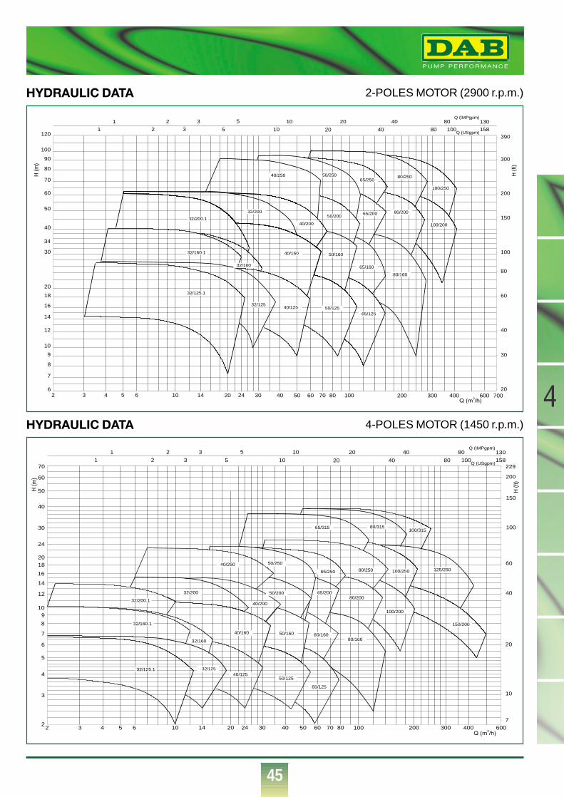
®
45
2-POLES MOTOR (2900 r.p.m.)HYDRAULIC DATA
H (f
t)
8
12
10
9
6
7
20
18
16
14
40
30
34
70
60
50
120
100
90
80
H (m
)
130
1
1 2 3 5 10 20 40 80
2 3 5 10 20 40 80 100 158
Q (IMPgpm)
Q (USgpm)
20
30
40
80
60
100
150
200
300
390
2 6543 1410 2420 30 8070605040 200100 600400300 700
32/200
40/200
50/20065/200
50/160
65/160
32/125
40/250 50/250
80/160
65/250
80/200
65/12550/12540/125
40/160
32/125.1
32/160.1
32/200.1
32/160
100/200
80/250
100/250
Q (m3/h)
4-POLES MOTOR (1450 r.p.m.)HYDRAULIC DATA
2
4
3
9
8
7
6
5
2018
16
14
12
10
40
30
24
50
70
60
H (m
)
2 6543 24201410 100807060504030 400300200 600
20
40
60
100
229
200
150
10
H (f
t)
130
1
1 2 3 5 10 20 40 80
2 3 5 10 20 40 80 100 158
Q (IMPgpm)
Q (USgpm)
7
50/20032/200
40/200
50/160 65/160
65/200
40/125
80/160
40/250 50/250
65/250
65/315
80/200
80/315
125/250
32/125
50/125
65/125
100/200
100/315
100/250
40/160
80/250
150/200
32/200.1
32/160.1
32/160
32/125.1
Q (m3/h)
4
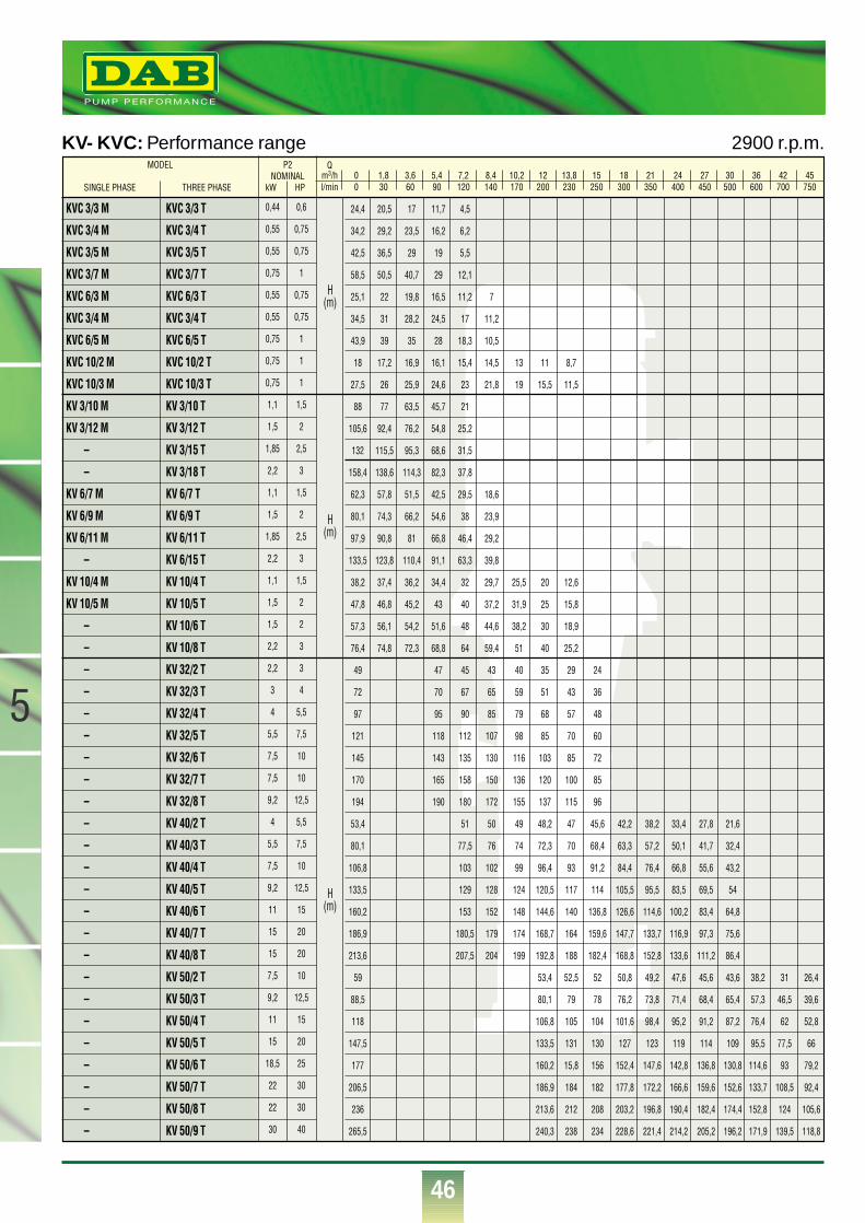
®
46
5
KV- KVC: Performance range 2900 r.p.m.P2
NOMINALkW HP
Qm3/h 0 1,8 3,6 5,4 7,2 8,4 10,2 12 13,8 15 18 21 24 27 30 36 42 45l/min 0 30 60 90 120 140 170 200 230 250 300 350 400 450 500 600 700 750
24,4 20,5 17 11,7 4,5
34,2 29,2 23,5 16,2 6,2
42,5 36,5 29 19 5,5
58,5 50,5 40,7 29 12,1
25,1 22 19,8 16,5 11,2 7
34,5 31 28,2 24,5 17 11,2
43,9 39 35 28 18,3 10,5
18 17,2 16,9 16,1 15,4 14,5 13 11 8,7
27,5 26 25,9 24,6 23 21,8 19 15,5 11,5
88 77 63,5 45,7 21
105,6 92,4 76,2 54,8 25,2
132 115,5 95,3 68,6 31,5
158,4 138,6 114,3 82,3 37,8
62,3 57,8 51,5 42,5 29,5 18,6
80,1 74,3 66,2 54,6 38 23,9
97,9 90,8 81 66,8 46,4 29,2
133,5 123,8 110,4 91,1 63,3 39,8
38,2 37,4 36,2 34,4 32 29,7 25,5 20 12,6
47,8 46,8 45,2 43 40 37,2 31,9 25 15,8
57,3 56,1 54,2 51,6 48 44,6 38,2 30 18,9
76,4 74,8 72,3 68,8 64 59,4 51 40 25,2
49 47 45 43 40 35 29 24
72 70 67 65 59 51 43 36
97 95 90 85 79 68 57 48
121 118 112 107 98 85 70 60
145 143 135 130 116 103 85 72
170 165 158 150 136 120 100 85
194 190 180 172 155 137 115 96
53,4 51 50 49 48,2 47 45,6 42,2 38,2 33,4 27,8 21,6
80,1 77,5 76 74 72,3 70 68,4 63,3 57,2 50,1 41,7 32,4
106,8 103 102 99 96,4 93 91,2 84,4 76,4 66,8 55,6 43,2
133,5 129 128 124 120,5 117 114 105,5 95,5 83,5 69,5 54
160,2 153 152 148 144,6 140 136,8 126,6 114,6 100,2 83,4 64,8
186,9 180,5 179 174 168,7 164 159,6 147,7 133,7 116,9 97,3 75,6
213,6 207,5 204 199 192,8 188 182,4 168,8 152,8 133,6 111,2 86,4
59 53,4 52,5 52 50,8 49,2 47,6 45,6 43,6 38,2 31 26,4
88,5 80,1 79 78 76,2 73,8 71,4 68,4 65,4 57,3 46,5 39,6
118 106,8 105 104 101,6 98,4 95,2 91,2 87,2 76,4 62 52,8
147,5 133,5 131 130 127 123 119 114 109 95,5 77,5 66
177 160,2 15,8 156 152,4 147,6 142,8 136,8 130,8 114,6 93 79,2
206,5 186,9 184 182 177,8 172,2 166,6 159,6 152,6 133,7 108,5 92,4
236 213,6 212 208 203,2 196,8 190,4 182,4 174,4 152,8 124 105,6
265,5 240,3 238 234 228,6 221,4 214,2 205,2 196,2 171,9 139,5 118,8
KVC 3/3 M
KVC 3/4 M
KVC 3/5 M
KVC 3/7 M
KVC 6/3 M
KVC 3/4 M
KVC 6/5 M
KVC 10/2 M
KVC 10/3 M
KV 3/10 M
KV 3/12 M
–
–
KV 6/7 M
KV 6/9 M
KV 6/11 M
–
KV 10/4 M
KV 10/5 M
–
–
–
–
–
–
–
–
–
–
–
–
–
–
–
–
–
–
–
–
–
–
–
–
KVC 3/3 T
KVC 3/4 T
KVC 3/5 T
KVC 3/7 T
KVC 6/3 T
KVC 3/4 T
KVC 6/5 T
KVC 10/2 T
KVC 10/3 T
KV 3/10 T
KV 3/12 T
KV 3/15 T
KV 3/18 T
KV 6/7 T
KV 6/9 T
KV 6/11 T
KV 6/15 T
KV 10/4 T
KV 10/5 T
KV 10/6 T
KV 10/8 T
KV 32/2 T
KV 32/3 T
KV 32/4 T
KV 32/5 T
KV 32/6 T
KV 32/7 T
KV 32/8 T
KV 40/2 T
KV 40/3 T
KV 40/4 T
KV 40/5 T
KV 40/6 T
KV 40/7 T
KV 40/8 T
KV 50/2 T
KV 50/3 T
KV 50/4 T
KV 50/5 T
KV 50/6 T
KV 50/7 T
KV 50/8 T
KV 50/9 T
0,44
0,55
0,55
0,75
0,55
0,55
0,75
0,75
0,75
1,1
1,5
1,85
2,2
1,1
1,5
1,85
2,2
1,1
1,5
1,5
2,2
2,2
3
4
5,5
7,5
7,5
9,2
4
5,5
7,5
9,2
11
15
15
7,5
9,2
11
15
18,5
22
22
30
0,6
0,75
0,75
1
0,75
0,75
1
1
1
1,5
2
2,5
3
1,5
2
2,5
3
1,5
2
2
3
3
4
5,5
7,5
10
10
12,5
5,5
7,5
10
12,5
15
20
20
10
12,5
15
20
25
30
30
40
MODEL
SINGLE PHASE THREE PHASE
H(m)
H(m)
H(m)
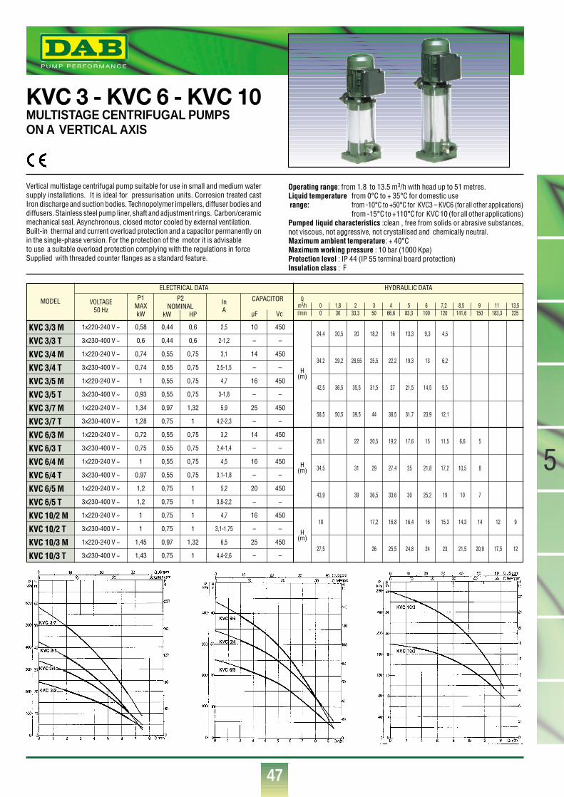
47
5
®
MODEL
KVC 3/3 M
KVC 3/3 T
KVC 3/4 M
KVC 3/4 T
KVC 3/5 M
KVC 3/5 T
KVC 3/7 M
KVC 3/7 T
KVC 6/3 M
KVC 6/3 T
KVC 6/4 M
KVC 6/4 T
KVC 6/5 M
KVC 6/5 T
KVC 10/2 M
KVC 10/2 T
KVC 10/3 M
KVC 10/3 T
VOLTAGE50 Hz
P1MAXkW
InA
1x220-240 V ~
3x230-400 V ~
1x220-240 V ~
3x230-400 V ~
1x220-240 V ~
3x230-400 V ~
1x220-240 V ~
3x230-400 V ~
1x220-240 V ~
3x230-400 V ~
1x220-240 V ~
3x230-400 V ~
1x220-240 V ~
3x230-400 V ~
1x220-240 V ~
3x230-400 V ~
1x220-240 V ~
3x230-400 V ~
0,58
0,6
0,74
0,74
1
0,93
1,34
1,28
0,72
0,75
1
0,97
1,2
1,2
1
1
1,45
1,43
0,44
0,44
0,55
0,55
0,55
0,55
0,97
0,75
0,55
0,55
0,55
0,55
0,75
0,75
0,75
0,75
0,97
0,75
0,6
0,6
0,75
0,75
0,75
0,75
1,32
1
0,75
0,75
0,75
0,75
1
1
1
1
1,32
1
10
–
14
–
16
–
25
–
14
–
16
–
20
–
16
–
25
–
450
–
450
–
450
–
450
–
450
–
450
–
450
–
450
–
450
–
H(m)
H(m)
H(m)
2,5
2-1,2
3,1
2,5-1,5
4,7
3-1,8
5,9
4,2-2,3
3,2
2,4-1,4
4,5
3,1-1,8
5,2
3,8-2,2
4,7
3,1-1,75
6,5
4,4-2,6
ELECTRICAL DATA HYDRAULIC DATA
P2NOMINAL
kW HP
CAPACITOR
µF Vc
Qm3/h 0 1,8 2 3 4 5 6 7,2 8,5 9 11 13,5l/min 0 30 33,3 50 66,6 83,3 100 120 141,6 150 183,3 225
24,4 20,5 20 18,2 16 13,3 9,3 4,5
34,2 29,2 28,55 25,5 22,2 19,3 13 6,2
42,5 36,5 35,5 31,5 27 21,5 14,5 5,5
58,5 50,5 39,5 44 38,5 31,7 23,9 12,1
25,1 22 20,5 19,2 17,6 15 11,5 6,6 5
34,5 31 29 27,4 25 21,8 17,2 10,5 8
43,9 39 36,5 33,6 30 25,2 19 10 7
18 17,2 16,8 16,4 16 15,3 14,3 14 12 9
27,5 26 25,5 24,8 24 23 21,5 20,9 17,5 12
KVC 3 - KVC 6 - KVC 10MULTISTAGE CENTRIFUGAL PUMPS ON A VERTICAL AXIS
Vertical multistage centrifugal pump suitable for use in small and medium watersupply installations. It is ideal for pressurisation units. Corrosion treated castIron discharge and suction bodies. Technopolymer impellers, diffuser bodies anddiffusers. Stainless steel pump liner, shaft and adjustment rings. Carbon/ceramicmechanical seal. Asynchronous, closed motor cooled by external ventilation.Built-in thermal and current overload protection and a capacitor permanently onin the single-phase version. For the protection of the motor it is advisableto use a suitable overload protection complying with the regulations in forceSupplied with threaded counter flanges as a standard feature.
Operating range: from 1.8 to 13.5 m3/h with head up to 51 metres.Liquid temperature from 0°C to + 35°C for domestic use range: from -10°C to +50°C for KVC3 – KVC6 (for all other applications)
from -15°C to +110°C for KVC 10 (for all other applications)Pumped liquid characteristics :clean , free from solids or abrasive substances,not viscous, not aggressive, not crystallised and chemically neutral.Maximum ambient temperature: + 40°CMaximum working pressure : 10 bar (1000 Kpa) Protection level : IP 44 (IP 55 terminal board protection)Insulation class : F
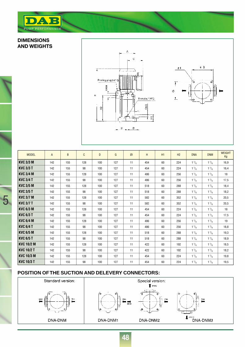
48
®
5
DIMENSIONSAND WEIGHTS
POSITION OF THE SUCTION AND DELEVERY CONNECTORS:
KVC 3/3 M 142 155 128 100 127 11 454 60 224 1 1/4 1 1/4 16,9
KVC 3/3 T 142 155 98 100 127 11 454 60 224 1 1/4 1 1/4 16,4
KVC 3/4 M 142 155 128 100 127 11 486 60 256 1 1/4 1 1/4 18
KVC 3/4 T 142 155 98 100 127 11 486 60 256 1 1/4 1 1/4 17,5
KVC 3/5 M 142 155 128 100 127 11 518 60 288 1 1/4 1 1/4 18,4
KVC 3/5 T 142 155 98 100 127 11 518 60 288 1 1/4 1 1/4 18,2
KVC 3/7 M 142 155 128 100 127 11 582 60 352 1 1/4 1 1/4 20,5
KVC 3/7 T 142 155 98 100 127 11 582 60 352 1 1/4 1 1/4 20,5
KVC 6/3 M 142 155 128 100 127 11 454 60 224 1 1/4 1 1/4 18
KVC 6/3 T 142 155 98 100 127 11 454 60 224 1 1/4 1 1/4 17,5
KVC 6/4 M 142 155 128 100 127 11 486 60 256 1 1/4 1 1/4 19
KVC 6/4 T 142 155 98 100 127 11 486 60 256 1 1/4 1 1/4 18,8
KVC 6/5 M 142 155 128 100 127 11 518 60 288 1 1/4 1 1/4 19,3
KVC 6/5 T 142 155 98 100 127 11 518 60 288 1 1/4 1 1/4 18,9
KVC 10/2 M 142 155 128 100 127 11 422 60 192 1 1/4 1 1/4 18,5
KVC 10/2 T 142 155 98 100 127 11 422 60 192 1 1/4 1 1/4 18,2
KVC 10/3 M 142 155 128 100 127 11 454 60 224 1 1/4 1 1/4 19,8
KVC 10/3 T 142 155 98 100 127 11 454 60 224 1 1/4 1 1/4 19,5
MODEL A B C D G ØI H H1 H2 DNA DNM WEIGHTKg
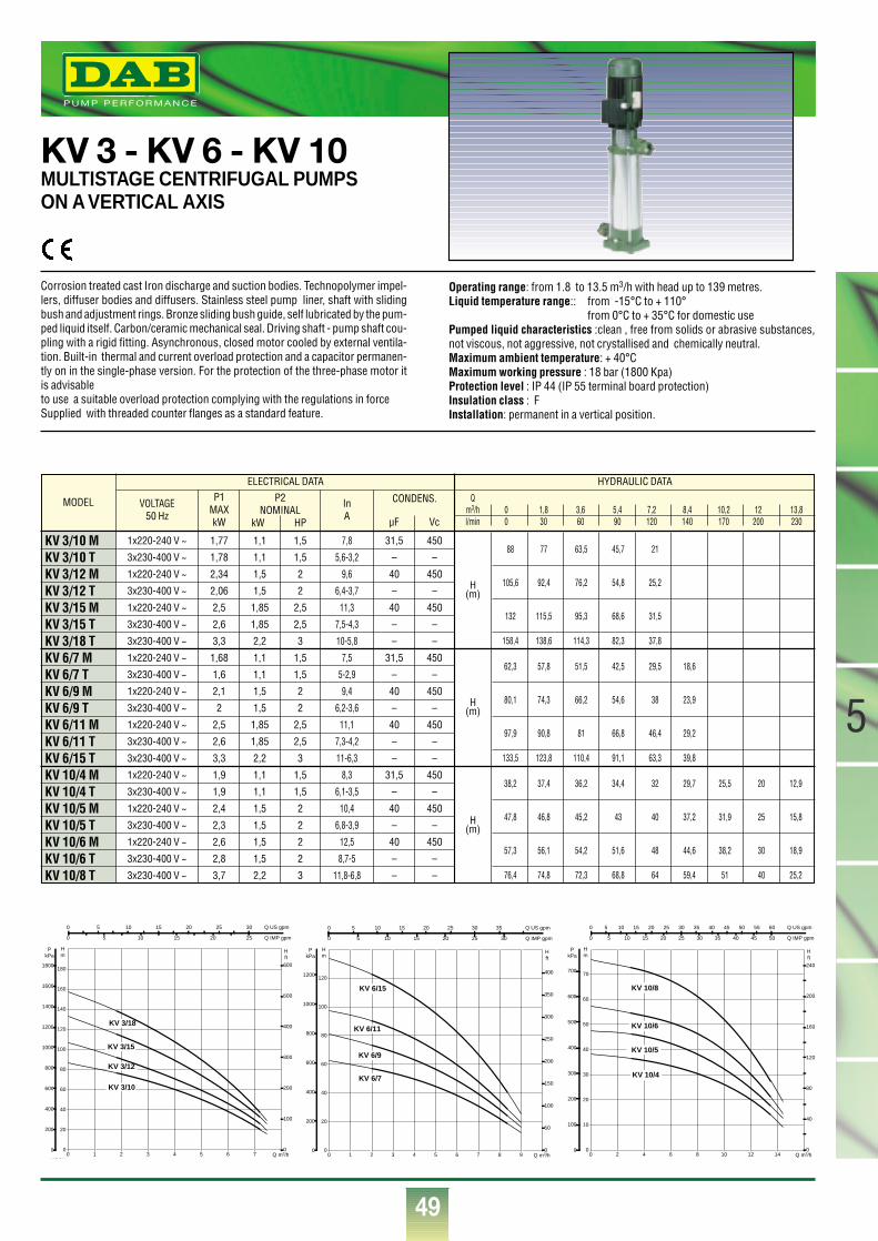
49
5
®
MODEL
KV 3/10 MKV 3/10 TKV 3/12 MKV 3/12 TKV 3/15 MKV 3/15 TKV 3/18 TKV 6/7 MKV 6/7 TKV 6/9 MKV 6/9 TKV 6/11 MKV 6/11 TKV 6/15 TKV 10/4 MKV 10/4 TKV 10/5 MKV 10/5 TKV 10/6 MKV 10/6 TKV 10/8 T
VOLTAGE50 Hz
P1MAXkW
InA
1x220-240 V ~
3x230-400 V ~
1x220-240 V ~
3x230-400 V ~
1x220-240 V ~
3x230-400 V ~
3x230-400 V ~
1x220-240 V ~
3x230-400 V ~
1x220-240 V ~
3x230-400 V ~
1x220-240 V ~
3x230-400 V ~
3x230-400 V ~
1x220-240 V ~
3x230-400 V ~
1x220-240 V ~
3x230-400 V ~
1x220-240 V ~
3x230-400 V ~
3x230-400 V ~
1,77
1,78
2,34
2,06
2,5
2,6
3,3
1,68
1,6
2,1
2
2,5
2,6
3,3
1,9
1,9
2,4
2,3
2,6
2,8
3,7
1,1
1,1
1,5
1,5
1,85
1,85
2,2
1,1
1,1
1,5
1,5
1,85
1,85
2,2
1,1
1,1
1,5
1,5
1,5
1,5
2,2
1,5
1,5
2
2
2,5
2,5
3
1,5
1,5
2
2
2,5
2,5
3
1,5
1,5
2
2
2
2
3
31,5
–
40
–
40
–
–
31,5
–
40
–
40
–
–
31,5
–
40
–
40
–
–
450
–
450
–
450
–
–
450
–
450
–
450
–
–
450
–
450
–
450
–
–
H(m)
H(m)
H(m)
7,8
5,6-3,2
9,6
6,4-3,7
11,3
7,5-4,3
10-5,8
7,5
5-2,9
9,4
6,2-3,6
11,1
7,3-4,2
11-6,3
8,3
6,1-3,5
10,4
6,8-3,9
12,5
8,7-5
11,8-6,8
ELECTRICAL DATA HYDRAULIC DATA
P2NOMINAL
kW HP
CONDENS.
µF Vc
Qm3/h 0 1,8 3,6 5,4 7,2 8,4 10,2 12 13,8l/min 0 30 60 90 120 140 170 200 230
88 77 63,5 45,7 21
105,6 92,4 76,2 54,8 25,2
132 115,5 95,3 68,6 31,5
158,4 138,6 114,3 82,3 37,8
62,3 57,8 51,5 42,5 29,5 18,6
80,1 74,3 66,2 54,6 38 23,9
97,9 90,8 81 66,8 46,4 29,2
133,5 123,8 110,4 91,1 63,3 39,8
38,2 37,4 36,2 34,4 32 29,7 25,5 20 12,9
47,8 46,8 45,2 43 40 37,2 31,9 25 15,8
57,3 56,1 54,2 51,6 48 44,6 38,2 30 18,9
76,4 74,8 72,3 68,8 64 59,4 51 40 25,2
KV 3 - KV 6 - KV 10MULTISTAGE CENTRIFUGAL PUMPSON A VERTICAL AXIS
Corrosion treated cast Iron discharge and suction bodies. Technopolymer impel-lers, diffuser bodies and diffusers. Stainless steel pump liner, shaft with slidingbush and adjustment rings. Bronze sliding bush guide, self lubricated by the pum-ped liquid itself. Carbon/ceramic mechanical seal. Driving shaft - pump shaft cou-pling with a rigid fitting. Asynchronous, closed motor cooled by external ventila-tion. Built-in thermal and current overload protection and a capacitor permanen-tly on in the single-phase version. For the protection of the three-phase motor itis advisableto use a suitable overload protection complying with the regulations in forceSupplied with threaded counter flanges as a standard feature.
Operating range: from 1.8 to 13.5 m3/h with head up to 139 metres.Liquid temperature range:: from -15°C to + 110°
from 0°C to + 35°C for domestic usePumped liquid characteristics :clean , free from solids or abrasive substances,not viscous, not aggressive, not crystallised and chemically neutral.Maximum ambient temperature: + 40°CMaximum working pressure : 18 bar (1800 Kpa) Protection level : IP 44 (IP 55 terminal board protection)Insulation class : FInstallation: permanent in a vertical position.
0 Q m3/h1 2 3 4 5 6 70
20
40
60
80
100
120
140
160
180
Hm
0
200
400
600
800
1000
1200
1400
1600
1800
PkPa
NPSH
0
100
200
300
400
500
600
H ft
0 5 10 15 20 25 30 Q US gpm
0 5 10 15 20 25 Q IMP gpm
KV 3/18
KV 3/15
KV 3/12
KV 3/10
0 Q m3/h1 2 3 4 5 6 7 8 90
20
40
60
80
100
120
Hm
0
200
400
600
800
1000
1200
PkPa
0
50
100
150
200
250
300
350
400
H ft
0 5 10 15 20 25 30 35 Q US gpm
0 5 10 15 20 25 30 Q IMP gpm
KV 6/15
KV 6/11
KV 6/9
KV 6/7
0 Q m3/h2 4 6 8 10 12 140
10
20
30
40
50
60
70
Hm
0
100
200
300
400
500
600
700
PkPa
NPSH
0
40
80
120
160
200
240
H ft
0 5 10 15 20 25 30 35 40 45 50 55 60 Q US gpm
0 5 10 15 20 25 30 35 40 45 50 Q IMP gpm
KV 10/8
KV 10/6
KV 10/5
KV 10/4
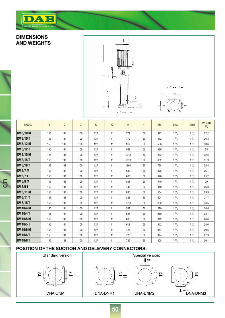
50
®
5
DIMENSIONSAND WEIGHTS
POSITION OF THE SUCTION AND DELEVERY CONNECTORS:
KV 3/10 M 155 111 100 127 11 779 60 472 1 1/4 1 1/4 27,2
KV 3/10 T 155 111 100 127 11 779 60 472 1 1/4 1 1/4 26,3
KV 3/12 M 155 116 100 127 11 917 60 536 1 1/4 1 1/4 30,6
KV 3/12 T 155 111 100 127 11 843 60 536 1 1/4 1 1/4 28
KV 3/15 M 155 116 100 127 11 1013 60 632 1 1/4 1 1/4 32,5
KV 3/15 T 155 116 100 127 11 1013 60 632 1 1/4 1 1/4 31,9
KV 3/18 T 155 116 100 127 11 1109 60 728 1 1/4 1 1/4 35,8
KV 6/7 M 155 111 100 127 11 683 60 376 1 1/4 1 1/4 26,1
KV 6/7 T 155 111 100 127 11 683 60 376 1 1/4 1 1/4 25,2
KV 6/9 M 155 116 100 127 11 821 60 440 1 1/4 1 1/4 29
KV 6/9 T 155 111 100 127 11 747 60 440 1 1/4 1 1/4 26,8
KV 6/11 M 155 116 100 127 11 885 60 504 1 1/4 1 1/4 29,9
KV 6/11 T 155 116 100 127 11 885 60 504 1 1/4 1 1/4 27,7
KV 6/15 T 155 116 100 127 11 1013 60 632 1 1/4 1 1/4 34,5
KV 10/4 M 155 111 100 127 11 587 60 280 1 1/4 1 1/4 24,4
KV 10/4 T 155 111 100 127 11 587 60 280 1 1/4 1 1/4 23,1
KV 10/5 M 155 116 100 127 11 693 60 312 1 1/4 1 1/4 26,6
KV 10/5 T 155 111 100 127 11 619 60 312 1 1/4 1 1/4 24,6
KV 10/6 M 155 116 100 127 11 725 60 344 1 1/4 1 1/4 29,5
KV 10/6 T 155 111 100 127 11 725 60 344 1 1/4 1 1/4 27,9
KV 10/8 T 155 116 100 127 11 789 60 408 1 1/4 1 1/4 30,1
MODEL B C D G IØ H H1 H2 DNA DNM WEIGHTKg
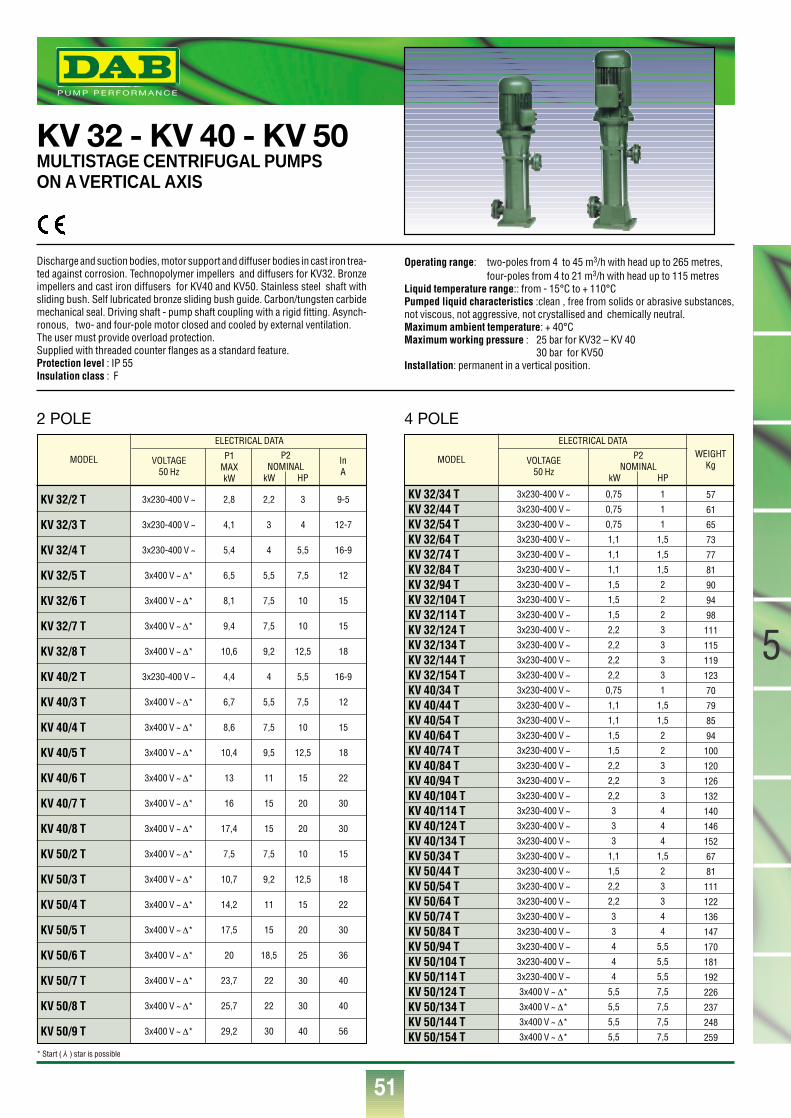
51
5
®
MODEL
KV 32/34 TKV 32/44 TKV 32/54 TKV 32/64 TKV 32/74 TKV 32/84 TKV 32/94 TKV 32/104 TKV 32/114 TKV 32/124 TKV 32/134 TKV 32/144 TKV 32/154 TKV 40/34 TKV 40/44 TKV 40/54 TKV 40/64 TKV 40/74 TKV 40/84 TKV 40/94 TKV 40/104 TKV 40/114 TKV 40/124 TKV 40/134 TKV 50/34 TKV 50/44 TKV 50/54 TKV 50/64 TKV 50/74 TKV 50/84 TKV 50/94 TKV 50/104 TKV 50/114 TKV 50/124 TKV 50/134 TKV 50/144 TKV 50/154 T
VOLTAGE50 Hz
WEIGHTKg
3x230-400 V ~
3x230-400 V ~
3x230-400 V ~
3x230-400 V ~
3x230-400 V ~
3x230-400 V ~
3x230-400 V ~
3x230-400 V ~
3x230-400 V ~
3x230-400 V ~
3x230-400 V ~
3x230-400 V ~
3x230-400 V ~
3x230-400 V ~
3x230-400 V ~
3x230-400 V ~
3x230-400 V ~
3x230-400 V ~
3x230-400 V ~
3x230-400 V ~
3x230-400 V ~
3x230-400 V ~
3x230-400 V ~
3x230-400 V ~
3x230-400 V ~
3x230-400 V ~
3x230-400 V ~
3x230-400 V ~
3x230-400 V ~
3x230-400 V ~
3x230-400 V ~
3x230-400 V ~
3x230-400 V ~
3x400 V ~ ∆*
3x400 V ~ ∆*
3x400 V ~ ∆*
3x400 V ~ ∆*
0,75
0,75
0,75
1,1
1,1
1,1
1,5
1,5
1,5
2,2
2,2
2,2
2,2
0,75
1,1
1,1
1,5
1,5
2,2
2,2
2,2
3
3
3
1,1
1,5
2,2
2,2
3
3
4
4
4
5,5
5,5
5,5
5,5
1
1
1
1,5
1,5
1,5
2
2
2
3
3
3
3
1
1,5
1,5
2
2
3
3
3
4
4
4
1,5
2
3
3
4
4
5,5
5,5
5,5
7,5
7,5
7,5
7,5
57
61
65
73
77
81
90
94
98
111
115
119
123
70
79
85
94
100
120
126
132
140
146
152
67
81
111
122
136
147
170
181
192
226
237
248
259
ELECTRICAL DATA
P2NOMINAL
kW HP
MODEL
KV 32/2 T
KV 32/3 T
KV 32/4 T
KV 32/5 T
KV 32/6 T
KV 32/7 T
KV 32/8 T
KV 40/2 T
KV 40/3 T
KV 40/4 T
KV 40/5 T
KV 40/6 T
KV 40/7 T
KV 40/8 T
KV 50/2 T
KV 50/3 T
KV 50/4 T
KV 50/5 T
KV 50/6 T
KV 50/7 T
KV 50/8 T
KV 50/9 T
VOLTAGE50 Hz
P1MAXkW
InA
3x230-400 V ~
3x230-400 V ~
3x230-400 V ~
3x400 V ~ ∆*
3x400 V ~ ∆*
3x400 V ~ ∆*
3x400 V ~ ∆*
3x230-400 V ~
3x400 V ~ ∆*
3x400 V ~ ∆*
3x400 V ~ ∆*
3x400 V ~ ∆*
3x400 V ~ ∆*
3x400 V ~ ∆*
3x400 V ~ ∆*
3x400 V ~ ∆*
3x400 V ~ ∆*
3x400 V ~ ∆*
3x400 V ~ ∆*
3x400 V ~ ∆*
3x400 V ~ ∆*
3x400 V ~ ∆*
2,8
4,1
5,4
6,5
8,1
9,4
10,6
4,4
6,7
8,6
10,4
13
16
17,4
7,5
10,7
14,2
17,5
20
23,7
25,7
29,2
2,2
3
4
5,5
7,5
7,5
9,2
4
5,5
7,5
9,5
11
15
15
7,5
9,2
11
15
18,5
22
22
30
3
4
5,5
7,5
10
10
12,5
5,5
7,5
10
12,5
15
20
20
10
12,5
15
20
25
30
30
40
9-5
12-7
16-9
12
15
15
18
16-9
12
15
18
22
30
30
15
18
22
30
36
40
40
56
ELECTRICAL DATA
P2NOMINAL
kW HP
KV 32 - KV 40 - KV 50MULTISTAGE CENTRIFUGAL PUMPSON A VERTICAL AXIS
Discharge and suction bodies, motor support and diffuser bodies in cast iron trea-ted against corrosion. Technopolymer impellers and diffusers for KV32. Bronzeimpellers and cast iron diffusers for KV40 and KV50. Stainless steel shaft withsliding bush. Self lubricated bronze sliding bush guide. Carbon/tungsten carbidemechanical seal. Driving shaft - pump shaft coupling with a rigid fitting. Asynch-ronous, two- and four-pole motor closed and cooled by external ventilation.The user must provide overload protection. Supplied with threaded counter flanges as a standard feature.Protection level : IP 55Insulation class : F
Operating range: two-poles from 4 to 45 m3/h with head up to 265 metres, four-poles from 4 to 21 m3/h with head up to 115 metres
Liquid temperature range:: from - 15°C to + 110°C Pumped liquid characteristics :clean , free from solids or abrasive substances,not viscous, not aggressive, not crystallised and chemically neutral.Maximum ambient temperature: + 40°CMaximum working pressure : 25 bar for KV32 – KV 40
30 bar for KV50Installation: permanent in a vertical position.
* Start ( ) star is possible Y
2 POLE 4 POLE
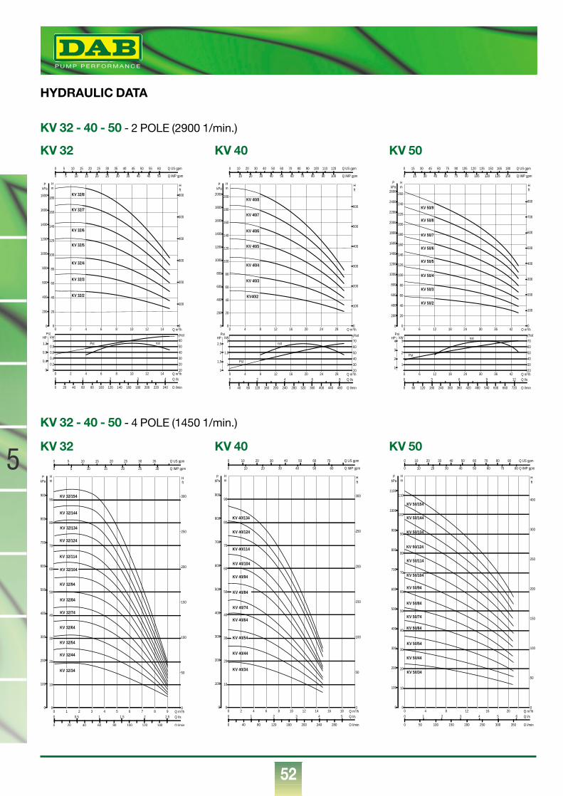
KV 32 - 40 - 50 - 2 POLE (2900 1/min.)
52
®
5
KV 32 KV 40 KV 50
KV 32 - 40 - 50 - 4 POLE (1450 1/min.)
KV 32 KV 40 KV 50
HYDRAULIC DATA
0 Q m3/h2 4 6 8 10 12 140
20
40
60
80
100
120
140
160
180
Hm
0
200
400
600
800
1000
1200
1400
1600
1800
PkPa
0
100
200
300
400
500
600
H ft
0 5 10 15 20 25 30 35 40 45 50 55 60 Q US gpm
0 5 10 15 20 25 30 35 40 45 50 Q IMP gpm
KV 32/8
KV 32/7
KV 32/6
KV 32/5
KV 32/4
KV 32/3
KV 32/2
0 Q m3/h2 4 6 8 10 12 14
η%st
0
0,2
0,4
0,6
0,8
1kW
10
20
30
40
50
60HP
0 20 40 60 80 100 120 140 160 180 200 220 240 Q l/min
0 1 2 3 4 Q l/s
Pst
0
0,4
0,8
1,2 ηstPst
0 Q m3/h4 8 12 16 20 24 28
η%st
1
1,5
2kW
20
30
40
50
60
70HP
0 40 80 120 160 200 240 280 320 360 400 440 480 Q l/min
0 2 4 6 8 Q l/s
Pst
1
1,5
2
2,5 ηst
Pst
0 Q m3/h4 8 12 16 20 24 280
20
40
60
80
100
120
140
160
180
200
Hm
0
200
400
600
800
1000
1200
1400
1600
1800
2000
PkPa
0
100
200
300
400
500
600
H ft
0 10 20 30 40 50 60 70 80 90 100 110 120 Q US gpm
0 10 20 30 40 50 60 70 80 90 100 Q IMP gpm
KV 40/8
KV 40/7
KV 40/6
KV 40/5
KV 40/4
KV 40/3
KV40/2
0 Q m3/h1 2 3 4 5 6 7 8 90
10
20
30
40
50
60
70
80
90
Hm
0
100
200
300
400
500
600
700
800
900
PkPa
0
50
100
150
200
250
300
0 20 40 60 80 100 120 140 Q l/min
0 0,5 1 1,5 2 2,5 Q l/s
H ft
0 5 10 15 20 25 30 35 Q US gpm
0 5 10 15 20 25 30 Q IMP gpm
KV 32/154
KV 32/144
KV 32/134
KV 32/124
KV 32/114
KV 32/104
KV 32/94
KV 32/84
KV 32/74
KV 32/64
KV 32/54
KV 32/44
KV 32/34
0 Q m3/h2 4 6 8 10 12 14 16 180
10
20
30
40
50
60
70
80
90
Hm
0
100
200
300
400
500
600
700
800
900
PkPa
0
50
100
150
200
250
300
0 40 80 120 160 200 240 280 Q l/min
0 1 2 3 4 5 Q l/s
H ft
0 10 20 30 40 50 60 70 Q US gpm
0 10 20 30 40 50 60 Q IMP gpm
KV 40/134
KV 40/124
KV 40/114
KV 40/104
KV 40/94
KV 40/84
KV 40/74
KV 40/64
KV 40/54
KV 40/44
KV 40/34
0 4 8 12 16 20 Q m3/h0
10
20
30
40
50
60
70
80
90
100
110
Hm
0
100
200
300
400
500
600
700
800
900
1000
1100
PkPa
0
50
100
150
200
250
300
400
0 50 100 150 200 250 300 350 Q l/min
0 1 2 3 4 5 6 Q l/s
H ft
0 10 20 30 40 50 60 70 80 90 Q US gpm
0 10 20 30 40 50 60 70 80 Q IMP gpm
KV 50/134
KV 50/124
KV 50/114
KV 50/104
KV 50/94
KV 50/84
KV 50/74
KV 50/64
KV 50/54
KV 50/44
KV 50/34
KV 50/144
KV 50/154
0 Q m3/h6 12 18 24 30 36 42
η%st
1
2
3kW
20
30
40
50
60
70HP
0 60 120 180 240 300 360 420 480 540 600 660 720 Q l/min
0 3 6 9 12 Q l/s
Pst
1
2
3
4ηst
Pst
0 Q m3/h6 12 18 24 30 36 420
20
40
60
80
100
120
140
160
180
200
220
240
260
Hm
0
200
400
600
800
1000
1200
1400
1600
1800
2000
2200
2400
2600
PkPa
0
100
200
300
400
500
600
700
800
H ft
0 15 30 45 60 75 90 105 120 135 150 165 180 Q US gpm
0 15 30 45 60 75 90 105 120 135 150 Q IMP gpm
KV 50/9
KV 50/8
KV 50/6
KV 50/5
KV 50/3
KV 50/2
KV 50/4
KV 50/7
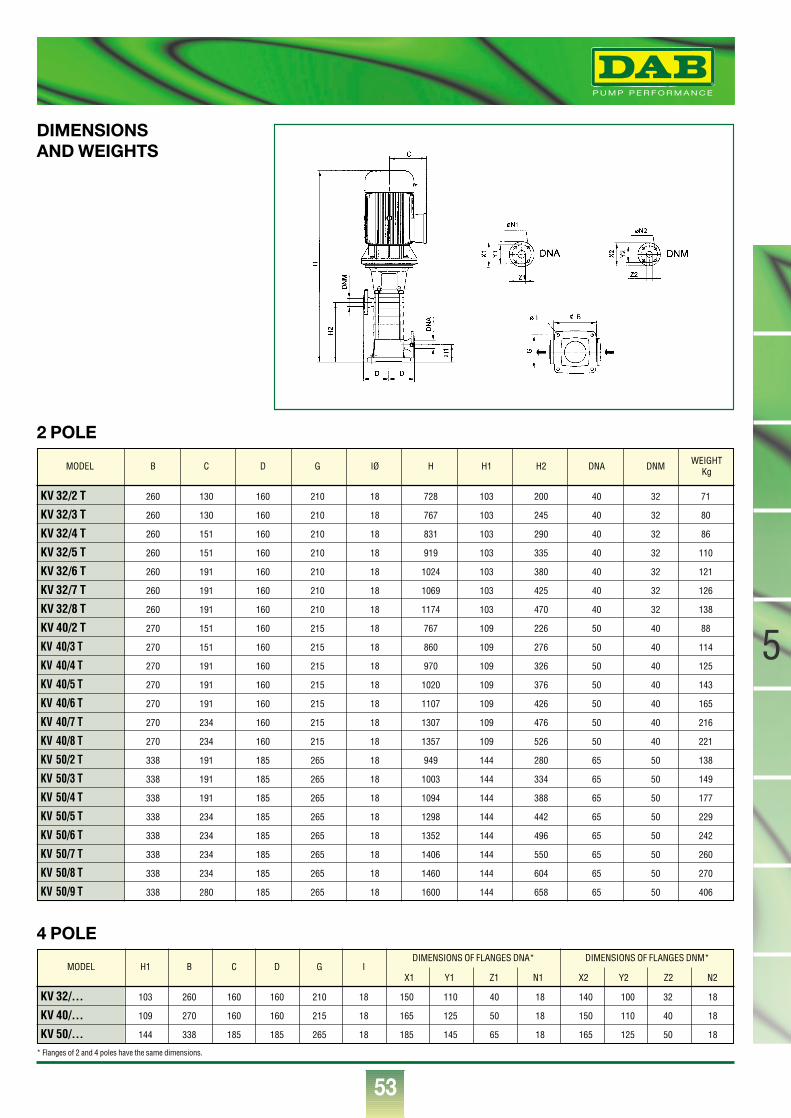
53
5
®
KV 32/2 T 260 130 160 210 18 728 103 200 40 32 71
KV 32/3 T 260 130 160 210 18 767 103 245 40 32 80
KV 32/4 T 260 151 160 210 18 831 103 290 40 32 86
KV 32/5 T 260 151 160 210 18 919 103 335 40 32 110
KV 32/6 T 260 191 160 210 18 1024 103 380 40 32 121
KV 32/7 T 260 191 160 210 18 1069 103 425 40 32 126
KV 32/8 T 260 191 160 210 18 1174 103 470 40 32 138
KV 40/2 T 270 151 160 215 18 767 109 226 50 40 88
KV 40/3 T 270 151 160 215 18 860 109 276 50 40 114
KV 40/4 T 270 191 160 215 18 970 109 326 50 40 125
KV 40/5 T 270 191 160 215 18 1020 109 376 50 40 143
KV 40/6 T 270 191 160 215 18 1107 109 426 50 40 165
KV 40/7 T 270 234 160 215 18 1307 109 476 50 40 216
KV 40/8 T 270 234 160 215 18 1357 109 526 50 40 221
KV 50/2 T 338 191 185 265 18 949 144 280 65 50 138
KV 50/3 T 338 191 185 265 18 1003 144 334 65 50 149
KV 50/4 T 338 191 185 265 18 1094 144 388 65 50 177
KV 50/5 T 338 234 185 265 18 1298 144 442 65 50 229
KV 50/6 T 338 234 185 265 18 1352 144 496 65 50 242
KV 50/7 T 338 234 185 265 18 1406 144 550 65 50 260
KV 50/8 T 338 234 185 265 18 1460 144 604 65 50 270
KV 50/9 T 338 280 185 265 18 1600 144 658 65 50 406
MODEL B C D G IØ H H1 H2 DNA DNM WEIGHTKg
KV 32/… 103 260 160 160 210 18 150 110 40 18 140 100 32 18
KV 40/… 109 270 160 160 215 18 165 125 50 18 150 110 40 18
KV 50/… 144 338 185 185 265 18 185 145 65 18 165 125 50 18
MODEL H1 B C D G IDIMENSIONS OF FLANGES DNA* DIMENSIONS OF FLANGES DNM*
X1 Y1 Z1 N1 X2 Y2 Z2 N2
2 POLE
4 POLE
DIMENSIONSAND WEIGHTS
* Flanges of 2 and 4 poles have the same dimensions.
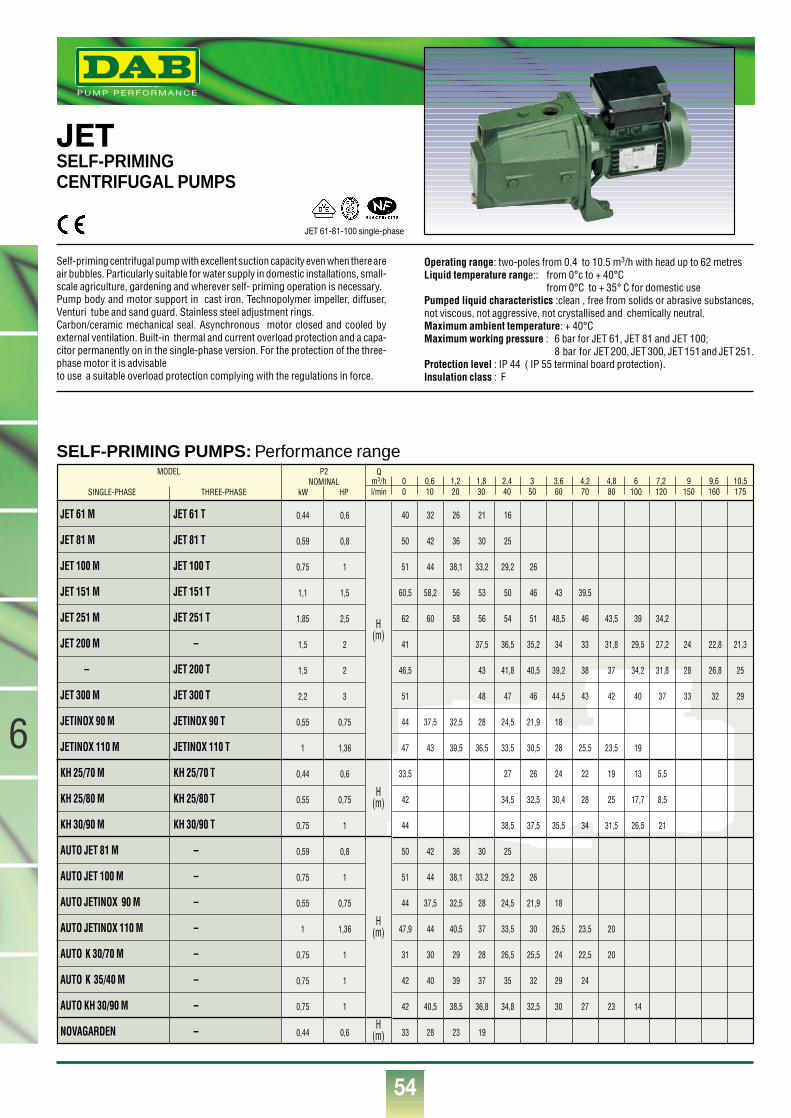
54
®
JETSELF-PRIMING CENTRIFUGAL PUMPS
Self-priming centrifugal pump with excellent suction capacity even when there areair bubbles. Particularly suitable for water supply in domestic installations, small-scale agriculture, gardening and wherever self- priming operation is necessary.Pump body and motor support in cast iron. Technopolymer impeller, diffuser,Venturi tube and sand guard. Stainless steel adjustment rings.Carbon/ceramic mechanical seal. Asynchronous motor closed and cooled byexternal ventilation. Built-in thermal and current overload protection and a capa-citor permanently on in the single-phase version. For the protection of the three-phase motor it is advisableto use a suitable overload protection complying with the regulations in force.
Operating range: two-poles from 0.4 to 10.5 m3/h with head up to 62 metresLiquid temperature range:: from 0°c to + 40°C
from 0°C to + 35° C for domestic usePumped liquid characteristics :clean , free from solids or abrasive substances,not viscous, not aggressive, not crystallised and chemically neutral.Maximum ambient temperature: + 40°CMaximum working pressure : 6 bar for JET 61, JET 81 and JET 100;
8 bar for JET 200, JET 300, JET 151 and JET 251.Protection level : IP 44 ( IP 55 terminal board protection).Insulation class : F
JET 61-81-100 single-phase
SELF-PRIMING PUMPS: Performance rangeP2
NOMINALkW HP
Qm3/h 0 0,6 1,2 1,8 2,4 3 3,6 4,2 4,8 6 7,2 9 9,6 10,5l/min 0 10 20 30 40 50 60 70 80 100 120 150 160 175
40 32 26 21 16
50 42 36 30 25
51 44 38,1 33,2 29,2 26
60,5 58,2 56 53 50 46 43 39,5
62 60 58 56 54 51 48,5 46 43,5 39 34,2
41 37,5 36,5 35,2 34 33 31,8 29,5 27,2 24 22,8 21,3
46,5 43 41,8 40,5 39,2 38 37 34,2 31,8 28 26,8 25
51 48 47 46 44,5 43 42 40 37 33 32 29
44 37,5 32,5 28 24,5 21,9 18
47 43 39,5 36,5 33,5 30,5 28 25,5 23,5 19
33,5 27 26 24 22 19 13 5,5
42 34,5 32,5 30,4 28 25 17,7 8,5
44 38,5 37,5 35,5 34 31,5 26,5 21
50 42 36 30 25
51 44 38,1 33,2 29,2 26
44 37,5 32,5 28 24,5 21,9 18
47,9 44 40,5 37 33,5 30 26,5 23,5 20
31 30 29 28 26,5 25,5 24 22,5 20
42 40 39 37 35 32 29 24
42 40,5 38,5 36,8 34,8 32,5 30 27 23 14
33 28 23 19
JET 61 M
JET 81 M
JET 100 M
JET 151 M
JET 251 M
JET 200 M
–
JET 300 M
JETINOX 90 M
JETINOX 110 M
KH 25/70 M
KH 25/80 M
KH 30/90 M
AUTO JET 81 M
AUTO JET 100 M
AUTO JETINOX 90 M
AUTO JETINOX 110 M
AUTO K 30/70 M
AUTO K 35/40 M
AUTO KH 30/90 M
NOVAGARDEN
JET 61 T
JET 81 T
JET 100 T
JET 151 T
JET 251 T
–
JET 200 T
JET 300 T
JETINOX 90 T
JETINOX 110 T
KH 25/70 T
KH 25/80 T
KH 30/90 T
–
–
–
–
–
–
–
–
0,44
0,59
0,75
1,1
1,85
1,5
1,5
2,2
0,55
1
0,44
0,55
0,75
0,59
0,75
0,55
1
0,75
0,75
0,75
0,44
0,6
0,8
1
1,5
2,5
2
2
3
0,75
1,36
0,6
0,75
1
0,8
1
0,75
1,36
1
1
1
0,6
MODEL
SINGLE-PHASE THREE-PHASE
H(m)
H(m)
H(m)
H(m)
6
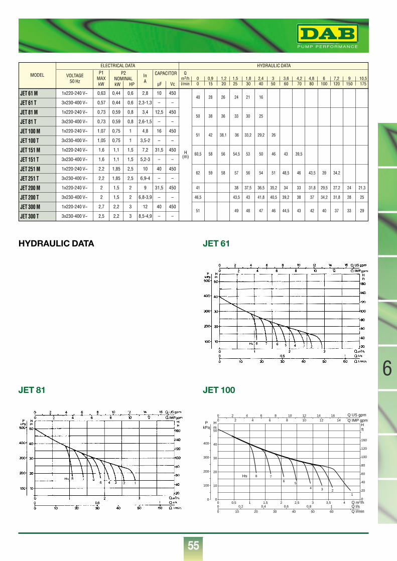
55
6
®
MODEL
JET 61 M
JET 61 T
JET 81 M
JET 81 T
JET 100 M
JET 100 T
JET 151 M
JET 151 T
JET 251 M
JET 251 T
JET 200 M
JET 200 T
JET 300 M
JET 300 T
VOLTAGE50 Hz
P1MAXkW
InA
1x220-240 V~
3x230-400 V~
1x220-240 V~
3x230-400 V~
1x220-240 V~
3x230-400 V~
1x220-240 V~
3x230-400 V~
1x220-240 V~
3x230-400 V~
1x220-240 V~
3x230-400 V~
1x220-240 V~
3x230-400 V~
0,63
0,57
0,73
0,73
1,07
1,05
1,6
1,6
2,2
2,2
2
2
2,7
2,5
0,44
0,44
0,59
0,59
0,75
0,75
1,1
1,1
1,85
1,85
1,5
1,5
2,2
2,2
10
–
12,5
–
16
–
31,5
–
40
–
31,5
–
40
–
450
–
450
–
450
–
450
–
450
–
450
–
450
–
0,6
0,6
0,8
0,8
1
1
1,5
1,5
2,5
2,5
2
2
3
3
H(m)
2,8
2,3-1,3
3,4
2,6-1,5
4,8
3,5-2
7,2
5,2-3
10
6,9-4
9
6,8-3,9
12
8,5-4,9
ELECTRICAL DATA HYDRAULIC DATA
P2NOMINALkW HP
CAPACITOR
µF Vc
Qm3/h 0 0,9 1,2 1,5 1,8 2,4 3 3,6 4,2 4,8 6 7,2 9 10,5l/min 0 15 20 25 30 40 50 60 70 80 100 120 150 175
40 28 26 24 21 16
50 38 36 33 30 25
51 42 38,1 36 33,2 29,2 26
60,5 58 56 54,5 53 50 46 43 39,5
62 59 58 57 56 54 51 48,5 46 43,5 39 34,2
41 38 37,5 36,5 35,2 34 33 31,8 29,5 27,2 24 21,3
46,5 43,5 43 41,8 40,5 39,2 38 37 34,2 31,8 28 25
51 49 48 47 46 44,5 43 42 40 37 33 29
HYDRAULIC DATA JET 61
JET 81 JET 100
Q m3/h0 0,5 1 1,5 2 2,5 3 3,5 40
10
20
30
40
50
0
20
40
60
80
100
120
160
0
00
Q l/sQ l/min
Q IMP gpmQ US gpm
0
0
0,2 0,4 0,6 0,8 1
10 20 30 40 50 60
Hm
Hft
PkPa
100
200
300
400
2 4 6 8 10 12 14 162 4 6 8 10 12 14
Hs 8 76
5
4 3 21
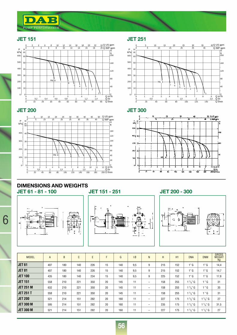
56
®
6
JET 151
DIMENSIONS AND WEIGHTS
JET 251
JET 200 JET 300
JET 61 - 81 - 100 JET 151 - 251 JET 200 - 300
JET 61 407 180 140 226 15 140 9,5 9 215 152 1” G 1” G 14,4
JET 81 407 180 140 226 15 140 9,5 9 215 152 1” G 1” G 14,7
JET 100 435 180 140 234 15 140 9,5 9 225 152 1” G 1” G 17,8
JET 151 558 210 221 350 20 145 11 – 158 255 1 1/4” G 1 ” G 31
JET 251 M 632 210 221 350 20 145 11 – 158 255 1 1/4” G 1 ” G 35
JET 251 T 558 210 221 350 20 145 11 – 158 255 1 1/4” G 1 ” G 31
JET 200 521 214 151 282 20 160 11 – 227 175 1 1/2” G 1 1/4” G 27
JET 300 M 595 214 151 282 20 160 11 – 235 175 1 1/2” G 1 1/4” G 31,5
JET 300 M 521 214 151 282 20 160 11 – 227 175 1 1/2” G 1 1/4” G 27
MODEL A B C E F G I Ø N H H1 DNA DNMGROSSWEIGHT
Kg
Q m3/h0 1 2 3 4 50
10
20
30
40
50
60
0
40
80
120
160
200
0
00
Q l/sQ l/min
Q IMP gpmQ US gpm
0
0
0,2 0,4 0,6 0,8 1 1,2 1,4
10 20 30 40 50 60 70 80 90
Hm
Hft
PkPa
100
200
300
400
500
600
2 4 6 8 10 12 14 16 18 20 22 242 4 6 8 10 12 14 16 18 20
Hs 86
2
7
5 4
1
3
Q m3/h0 1 2 3 4 5 6 7 8 90
10
20
30
40
50
60
0
40
80
120
160
200
0
00
Q l/sQ l/min
Q IMP gpmQ US gpm
0
0
0,5 1 1,5 2 2,5
20 40 60 80 100 120 140
Hm
Hft
PkPa
100
200
300
400
500
600
5 10 15 20 25 30 35 405 10 15 20 25 30
6
2
75
1
3
Hs 8
4
Q m3/h0 1 2 3 4 5 6 7 8 9 10 11 120
10
20
30
40
50
0
20
40
60
80
100
120
160
0
00
Q l/sQ l/min
Q IMP gpmQ US gpm
0
0
0,5 1 1,5 2 2,5 3
20 40 60 80 100 120 140 160 180 200
Hm
Hft
PkPa
100
200
300
400
5 10 15 20 25 30 35 40 45 505 10 15 20 25 30 35 40
Hs 86
3 2
75 4
1
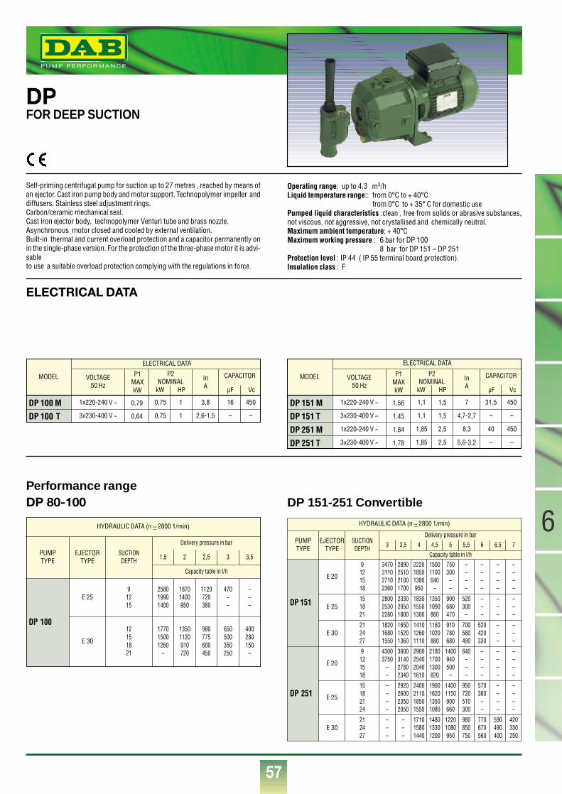
57
6
®
DPFOR DEEP SUCTION
Self-priming centrifugal pump for suction up to 27 metres , reached by means ofan ejector. Cast iron pump body and motor support. Technopolymer impeller anddiffusers. Stainless steel adjustment rings.Carbon/ceramic mechanical seal.Cast iron ejector body, technopolymer Venturi tube and brass nozzle.Asynchronous motor closed and cooled by external ventilation.Built-in thermal and current overload protection and a capacitor permanently onin the single-phase version. For the protection of the three-phase motor it is advi-sableto use a suitable overload protection complying with the regulations in force.
Operating range: up to 4.3 m3/h Liquid temperature range:: from 0°C to + 40°C
from 0°C to + 35° C for domestic usePumped liquid characteristics :clean , free from solids or abrasive substances,not viscous, not aggressive, not crystallised and chemically neutral.Maximum ambient temperature: + 40°CMaximum working pressure : 6 bar for DP 100
8 bar for DP 151 – DP 251 Protection level : IP 44 ( IP 55 terminal board protection).Insulation class : F
ELECTRICAL DATA
DP 80-100Performance range
DP 151-251 Convertible
MODEL
DP 100 M
DP 100 T
VOLTAGE50 Hz
P1MAXkW
InA
1x220-240 V ~
3x230-400 V ~
0,79
0,64
0,75
0,75
1
1
16
–
450
–
3,8
2,6-1,5
ELECTRICAL DATA
P2NOMINAL
kW HP
CAPACITOR
µF Vc
MODEL
DP 151 M
DP 151 T
DP 251 M
DP 251 T
VOLTAGE50 Hz
P1MAXkW
InA
1x220-240 V ~
3x230-400 V ~
1x220-240 V ~
3x230-400 V ~
1,56
1,45
1,84
1,78
1,1
1,1
1,85
1,85
1,5
1,5
2,5
2,5
31,5
–
40
–
450
–
450
–
7
4,7-2,7
8,3
5,6-3,2
ELECTRICAL DATA
P2NOMINAL
kW HP
CAPACITOR
µF Vc
HYDRAULIC DATA (n ∼ 2800 1/min)
PUMPTYPE
EJECTORTYPE
SUCTIONDEPTH
Delivery pressure in bar
Capacity table in l/h3 3,5 4 4,5 5 5,5 6 6,5 7
DP 151
E 20
9121518
E 25151821
3470311027102360
280025302280
E 30212427
182016801550
165015201360
141012601110
11601020880
910780680
700580490
520420330
233020501800
183015501300
13501090860
900680470
520300
–
2890251021001700
222018501380950
15001100640–
750300––
––––
––––
––––
––––
–––
–––
–––
–––
––––
––––
––––
–––
43003750
––
3600314027802340
2900254020401610
218017001300820
1400940500–
640–––
DP 251
E 20
9121518
––––
––––
570360
––
––––
–––
–––
171015801440
148013301200
12201080950
980850750
770670560
590490400
420330250
2920260023502050
2400211018501550
1900162013501080
14001150900660
950720510300
E 25
15182124
E 30212427
HYDRAULIC DATA (n ∼ 2800 1/min)
PUMPTYPE
EJECTORTYPE
SUCTIONDEPTH
Delivery pressure in bar
Capacity table in l/h
1,5 2 2,5 3 3,5
258019901400
177015001260
–
13501120910720
980775600450
650500350250
400280150–
18701400950
1120720380
470––
–––
DP 100
E 30
12151821
E 2591215
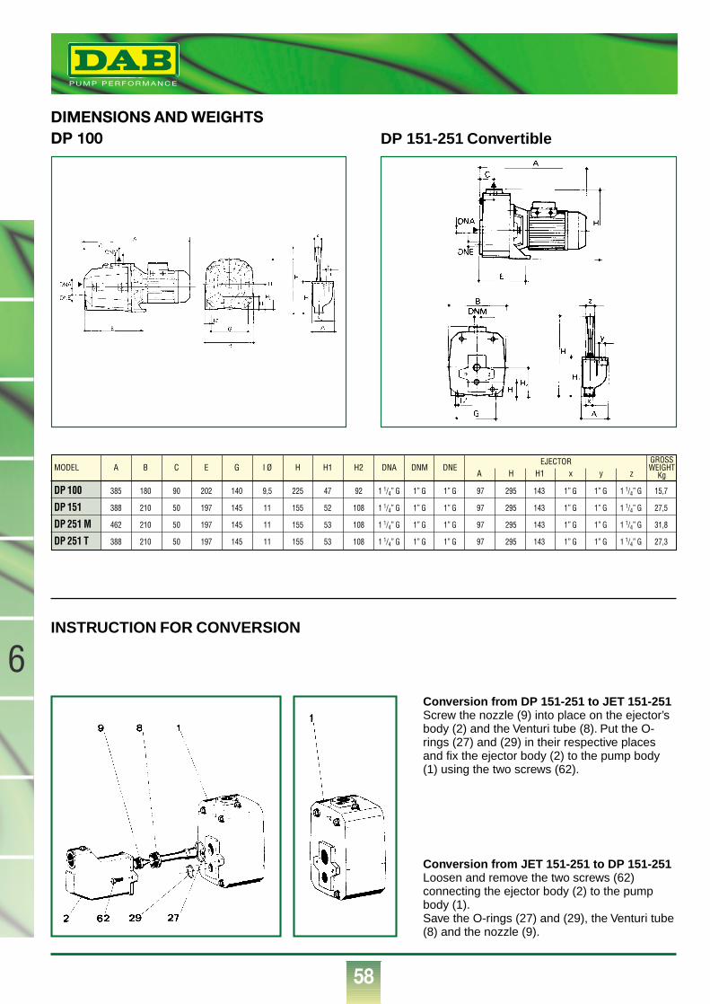
58
®
6
DP 100DIMENSIONS AND WEIGHTS
INSTRUCTION FOR CONVERSION
DP 151-251 Convertible
DP 100 385 180 90 202 140 9,5 225 47 92 1 1/4” G 1” G 1” G 97 295 143 1” G 1” G 1 1/4” G 15,7
DP 151 388 210 50 197 145 11 155 52 108 1 1/4” G 1” G 1” G 97 295 143 1” G 1” G 1 1/4” G 27,5
DP 251 M 462 210 50 197 145 11 155 53 108 1 1/4” G 1” G 1” G 97 295 143 1” G 1” G 1 1/4” G 31,8
DP 251 T 388 210 50 197 145 11 155 53 108 1 1/4” G 1” G 1” G 97 295 143 1” G 1” G 1 1/4” G 27,3
MODEL A B C E G I Ø H H1 H2 DNA DNM DNEEJECTOR
A H H1 x y z
GROSSWEIGHT
Kg
Conversion from DP 151-251 to JET 151-251Screw the nozzle (9) into place on the ejector’sbody (2) and the Venturi tube (8). Put the O-rings (27) and (29) in their respective placesand fix the ejector body (2) to the pump body(1) using the two screws (62).
Conversion from JET 151-251 to DP 151-251Loosen and remove the two screws (62)connecting the ejector body (2) to the pumpbody (1).Save the O-rings (27) and (29), the Venturi tube(8) and the nozzle (9).
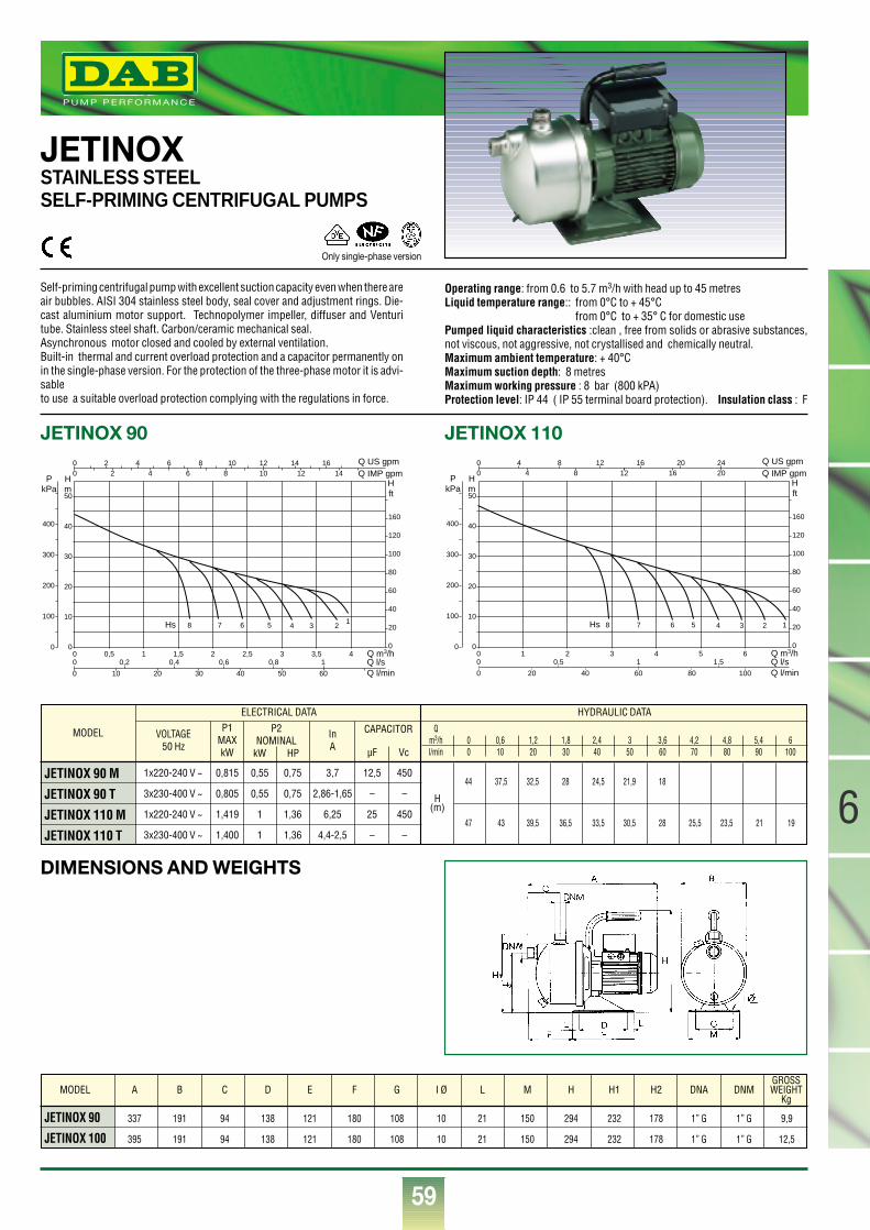
59
6
®
JETINOXSTAINLESS STEELSELF-PRIMING CENTRIFUGAL PUMPS
Self-priming centrifugal pump with excellent suction capacity even when there areair bubbles. AISI 304 stainless steel body, seal cover and adjustment rings. Die-cast aluminium motor support. Technopolymer impeller, diffuser and Venturitube. Stainless steel shaft. Carbon/ceramic mechanical seal.Asynchronous motor closed and cooled by external ventilation.Built-in thermal and current overload protection and a capacitor permanently onin the single-phase version. For the protection of the three-phase motor it is advi-sableto use a suitable overload protection complying with the regulations in force.
Operating range: from 0.6 to 5.7 m3/h with head up to 45 metresLiquid temperature range:: from 0°C to + 45°C
from 0°C to + 35° C for domestic usePumped liquid characteristics :clean , free from solids or abrasive substances,not viscous, not aggressive, not crystallised and chemically neutral.Maximum ambient temperature: + 40°CMaximum suction depth: 8 metresMaximum working pressure : 8 bar (800 kPA)Protection level: IP 44 ( IP 55 terminal board protection). Insulation class : F
MODEL
JETINOX 90 M
JETINOX 90 T
JETINOX 110 M
JETINOX 110 T
VOLTAGE50 Hz
P1MAXkW
InA
1x220-240 V ~
3x230-400 V ~
1x220-240 V ~
3x230-400 V ~
0,815
0,805
1,419
1,400
0,55
0,55
1
1
0,75
0,75
1,36
1,36
12,5
–
25
–
450
–
450
–
H(m)
3,7
2,86-1,65
6,25
4,4-2,5
ELECTRICAL DATA HYDRAULIC DATA
P2NOMINAL
kW HP
CAPACITOR
µF Vc
Qm3/h 0 0,6 1,2 1,8 2,4 3 3,6 4,2 4,8 5,4 6l/min 0 10 20 30 40 50 60 70 80 90 100
44 37,5 32,5 28 24,5 21,9 18
47 43 39,5 36,5 33,5 30,5 28 25,5 23,5 21 19
JETINOX 90 JETINOX 110
JETINOX 90 337 191 94 138 121 180 108 10 21 150 294 232 178 1” G 1” G 9,9
JETINOX 100 395 191 94 138 121 180 108 10 21 150 294 232 178 1” G 1” G 12,5
MODEL A B C D E F G I Ø L M H H1 H2 DNA DNMGROSSWEIGHT
Kg
Q m3/h0 1 2 3 4 5 60
10
20
30
40
50
0
20
40
60
80
100
120
160
0
00
Q l/sQ l/min
Q IMP gpmQ US gpm
0
0
0,5 1 1,5
20 40 60 80 100
Hm
Hft
PkPa
100
200
300
400
4 8 12 16 20 244 8 12 16 20
Hs 8 7 6 5 4 3 2 1
Q m3/h0 0,5 1 1,5 2 2,5 3 3,5 40
10
20
30
40
50
0
20
40
60
80
100
120
160
0
00
Q l/sQ l/min
Q IMP gpmQ US gpm
0
0
0,2 0,4 0,6 0,8 1
10 20 30 40 50 60
Hm
Hft
PkPa
100
200
300
400
2 4 6 8 10 12 14 162 4 6 8 10 12 14
Hs 8 7 6 5 4 3 21
DIMENSIONS AND WEIGHTS
Only single-phase version
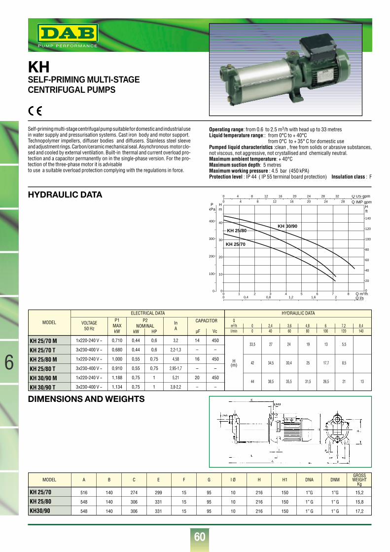
60
®
6
KHSELF-PRIMING MULTI-STAGECENTRIFUGAL PUMPS
Self-priming multi-stage centrifugal pump suitable for domestic and industrial usein water supply and pressurisation systems. Cast iron body and motor support.Technopolymer impellers, diffuser bodies and diffusers. Stainless steel sleeveand adjustment rings. Carbon/ceramic mechanical seal. Asynchronous motor clo-sed and cooled by external ventilation. Built-in thermal and current overload pro-tection and a capacitor permanently on in the single-phase version. For the pro-tection of the three-phase motor it is advisableto use a suitable overload protection complying with the regulations in force.
Operating range: from 0.6 to 2.5 m3/h with head up to 33 metresLiquid temperature range:: from 0°C to + 40°C
from 0°C to + 35° C for domestic usePumped liquid characteristics :clean , free from solids or abrasive substances,not viscous, not aggressive, not crystallised and chemically neutral.Maximum ambient temperature: + 40°CMaximum suction depth: 5 metresMaximum working pressure : 4.5 bar (450 kPA)Protection level : IP 44 ( IP 55 terminal board protection) Insulation class : F
MODEL
KH 25/70 M
KH 25/70 T
KH 25/80 M
KH 25/80 T
KH 30/90 M
KH 30/90 T
VOLTAGE50 Hz
P1MAXkW
InA
1x220-240 V ~
3x230-400 V ~
1x220-240 V ~
3x230-400 V ~
1x220-240 V ~
3x230-400 V ~
0,710
0,680
1,000
0,910
1,188
1,134
0,44
0,44
0,55
0,55
0,75
0,75
0,6
0,6
0,75
0,75
1
1
14
–
16
–
20
–
450
–
450
–
450
–
H(m)
3,2
2,2-1,3
4,58
2,95-1,7
5,21
3,8-2,2
ELECTRICAL DATA HYDRAULIC DATA
P2NOMINAL
kW HP
CAPACITOR
µF Vc
Qm3/h 0 2,4 3,6 4,8 6 7,2 8,4l/min 0 40 60 80 100 120 140
33,5 27 24 19 13 5,5
42 34,5 30,4 25 17,7 8,5
44 38,5 35,5 31,5 26,5 21 13
KH 25/70 516 140 274 299 15 95 10 216 150 1”G 1”G 15,2
KH 25/80 548 140 306 331 15 95 10 216 150 1” G 1” G 15,8
KH30/90 548 140 306 331 15 95 10 216 150 1” G 1” G 17,2
MODEL A B C E F G I Ø H H1 DNA DNMGROSSWEIGHT
Kg
Q m3/h0 1 2 3 4 5 6 7 80
10
20
30
40
0
20
40
60
80
100
120
140
0
0
0
Q l/sQ l/ i
Q IMP gpm
Q US gpm
0 0,4 0,8 1,2 1,6 2
Hm
Hft
PkPa
100
200
300
400
4 8 12 16 20 24 28 32
4 8 12 16 20 24 28
KH 30/90KH 25/80
KH 25/70
DIMENSIONS AND WEIGHTS
HYDRAULIC DATA
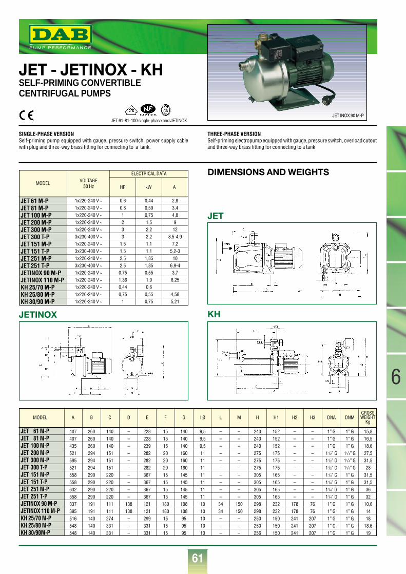
61
6
®
JET - JETINOX - KHSELF-PRIMING CONVERTIBLE CENTRIFUGAL PUMPS
SINGLE-PHASE VERSIONSelf-priming pump equipped with gauge, pressure switch, power supply cablewith plug and three-way brass fitting for connecting to a tank.
THREE-PHASE VERSIONSelf-priming electropump equipped with gauge, pressure switch, overload cutoutand three-way brass fitting for connecting to a tank
MODEL
JET 61 M-PJET 81 M-PJET 100 M-PJET 200 M-PJET 300 M-PJET 300 T-PJET 151 M-PJET 151 T-PJET 251 M-PJET 251 T-PJETINOX 90 M-PJETINOX 110 M-PKH 25/70 M-PKH 25/80 M-PKH 30/90 M-P
VOLTAGE50 Hz HP kW A
1x220-240 V ~1x220-240 V ~1x220-240 V ~1x220-240 V ~1x220-240 V ~3x230-400 V ~1x220-240 V ~3x230-400 V ~1x220-240 V ~3x230-400 V ~1x220-240 V ~1x220-240 V ~1x220-240 V ~1x220-240 V ~1x220-240 V ~
2,83,44,8912
8,5-4,97,2
5,2-310
6,9-43,76,25
4,585,21
0,60,81233
1,51,52,52,50,751,360,440,75
1
0,440,590,751,52,22,21,11,11,851,850,551,00,60,550,75
ELECTRICAL DATA
JET 61 M-P 407 260 140 – 228 15 140 9,5 – – 240 152 – – 1” G 1” G 15,8JET 81 M-P 407 260 140 – 228 15 140 9,5 – – 240 152 – – 1” G 1” G 16,5JET 100 M-P 435 260 140 – 239 15 140 9,5 – – 240 152 – – 1” G 1” G 18,6JET 200 M-P 521 294 151 – 282 20 160 11 – – 275 175 – – 11/2” G 11/4” G 27,5JET 300 M-P 595 294 151 – 282 20 160 11 – – 275 175 – – 11/2” G 11/4” G 31,5JET 300 T-P 521 294 151 – 282 20 160 11 – – 275 175 – – 11/2” G 11/4” G 28JET 151 M-P 558 290 220 – 367 15 145 11 – – 305 165 – – 11/4” G 1” G 31,5JET 151 T-P 558 290 220 – 367 15 145 11 – – 305 165 – – 11/4” G 1” G 31,5JET 251 M-P 632 290 220 – 367 15 145 11 – – 305 165 – – 11/4” G 1” G 36JET 251 T-P 558 290 220 – 367 15 145 11 – – 305 165 – – 11/4” G 1” G 32JETINOX 90 M-P 337 191 111 138 121 180 108 10 34 150 298 232 178 76 1” G 1” G 10,6JETINOX 110 M-P 395 191 111 138 121 180 108 10 34 150 298 232 178 76 1” G 1” G 14KH 25/70 M-P 516 140 274 – 299 15 95 10 – – 250 150 241 207 1” G 1” G 18KH 25/80 M-P 548 140 331 – 331 15 95 10 – – 250 150 241 207 1” G 1” G 18,6KH 30/90M-P 548 140 331 – 331 15 95 10 – – 256 150 241 207 1” G 1” G 19
MODEL A B C D E F G I Ø L M H H1 H2 H3 DNA DNM
JETINOX KH
DIMENSIONS AND WEIGHTS
GROSSWEIGHT
Kg
JET 61-81-100 single-phase and JETINOXJET INOX 90 M-P
JET
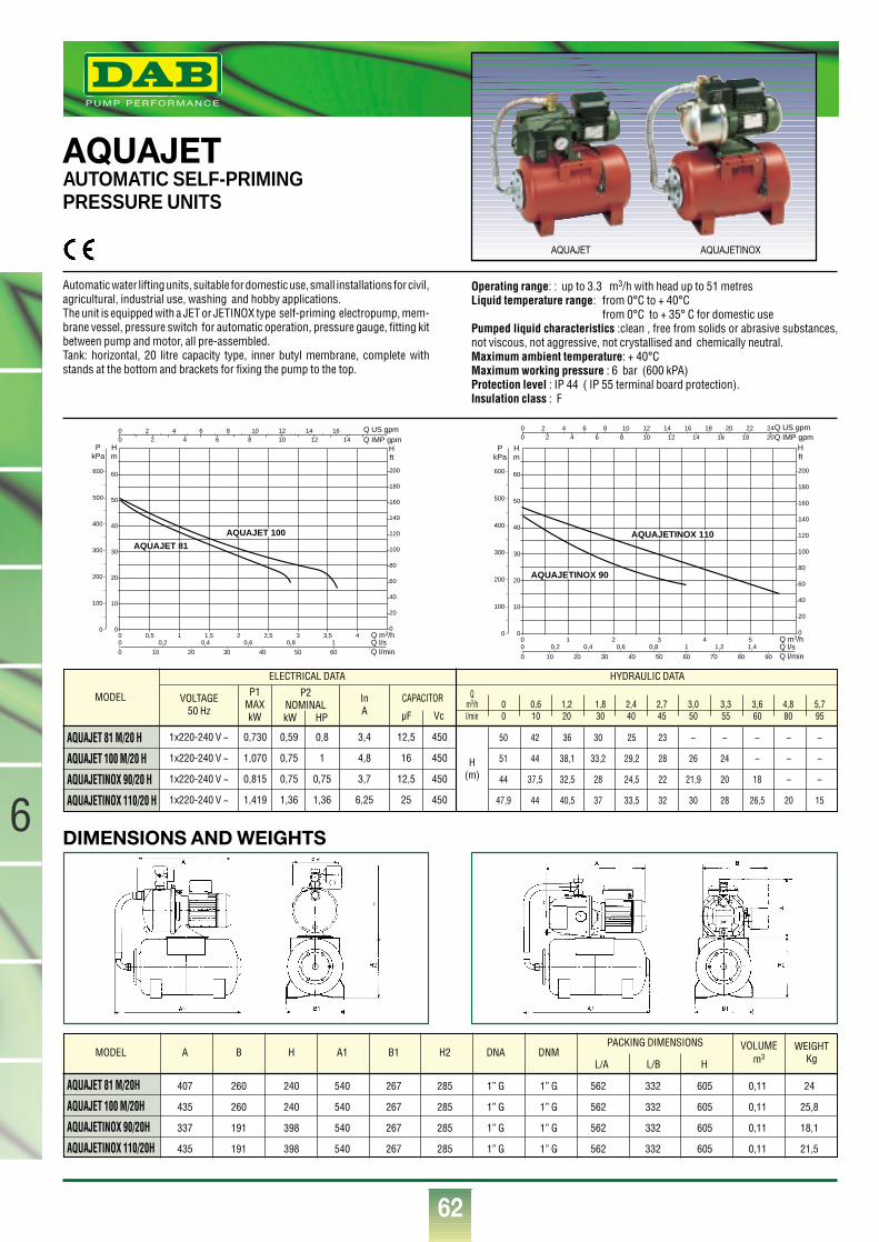
62
®
6
AQUAJETAUTOMATIC SELF-PRIMING PRESSURE UNITS
Automatic water lifting units, suitable for domestic use, small installations for civil,agricultural, industrial use, washing and hobby applications. The unit is equipped with a JET or JETINOX type self-priming electropump, mem-brane vessel, pressure switch for automatic operation, pressure gauge, fitting kitbetween pump and motor, all pre-assembled.Tank: horizontal, 20 litre capacity type, inner butyl membrane, complete withstands at the bottom and brackets for fixing the pump to the top.
Operating range: : up to 3.3 m3/h with head up to 51 metresLiquid temperature range: from 0°C to + 40°C
from 0°C to + 35° C for domestic usePumped liquid characteristics :clean , free from solids or abrasive substances,not viscous, not aggressive, not crystallised and chemically neutral.Maximum ambient temperature: + 40°CMaximum working pressure : 6 bar (600 kPA)Protection level : IP 44 ( IP 55 terminal board protection).Insulation class : F
Q m3/h0 1 2 3 4 50
10
20
30
40
50
60
0
20
40
60
80
100
120
140
160
180
200
0
00
Q l/sQ l/min
Q IMP gpmQ US gpm
0
0
0,2 0,4 0,6 0,8 1 1,2 1,4
10 20 30 40 50 60 70 80 90
Hm
Hft
PkPa
100
200
300
400
500
600
2 4 6 8 10 12 14 16 18 20 22 242 4 6 8 10 12 14 16 18 20
AQUAJETINOX 110
AQUAJETINOX 90
Q m3/h0 0,5 1 1,5 2 2,5 3 3,5 40
10
20
30
40
50
0
20
40
60
80
100
120
140
160
180
200
0
00
Q l/sQ l/min
Q IMP gpmQ US gpm
0
0
0,2 0,4 0,6 0,8 1
10 20 30 40 50 60
Hm
Hft
PkPa
100
200
300
400
2 4 6 8 10 12 14 162 4 6 8 10 12 14
AQUAJET 100
AQUAJET 81
60
500
600
DIMENSIONS AND WEIGHTS
MODEL
AQUAJET 81 M/20 H
AQUAJET 100 M/20 H
AQUAJETINOX 90/20 H
AQUAJETINOX 110/20 H
VOLTAGE50 Hz
P1MAXkW
InA
1x220-240 V ~
1x220-240 V ~
1x220-240 V ~
1x220-240 V ~
0,730
1,070
0,815
1,419
0,59
0,75
0,75
1,36
0,8
1
0,75
1,36
12,5
16
12,5
25
450
450
450
450
H(m)
3,4
4,8
3,7
6,25
ELECTRICAL DATA HYDRAULIC DATA
P2NOMINALkW HP
CAPACITOR
µF Vc
Qm3/h 0 0,6 1,2 1,8 2,4 2,7 3,0 3,3 3,6 4,8 5,7l/min 0 10 20 30 40 45 50 55 60 80 95
50 42 36 30 25 23 – – – – –
51 44 38,1 33,2 29,2 28 26 24 – – –
44 37,5 32,5 28 24,5 22 21,9 20 18 – –
47,9 44 40,5 37 33,5 32 30 28 26,5 20 15
AQUAJET 81 M/20H 407 260 240 540 267 285 1” G 1” G 562 332 605 0,11 24
AQUAJET 100 M/20H 435 260 240 540 267 285 1” G 1” G 562 332 605 0,11 25,8
AQUAJETINOX 90/20H 337 191 398 540 267 285 1” G 1” G 562 332 605 0,11 18,1
AQUAJETINOX 110/20H 435 191 398 540 267 285 1” G 1” G 562 332 605 0,11 21,5
MODEL A B H A1 B1 H2 DNA DNMPACKING DIMENSIONS WEIGHT
KgVOLUME
m3L/A L/B H
AQUAJETINOXAQUAJET
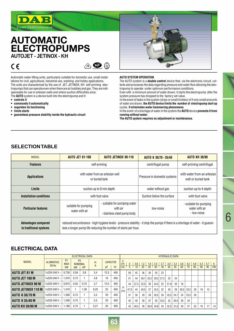
63
6
®
AUTOMATIC ELECTROPUMPSAUTOJET - JETINOX - KH
Automatic water lifting units, particularly suitable for domestic use, small instal-lations for civil, agricultural, industrial use, washing and hobby applications. The units are characterised by the use of JET, JETINOX, KH self-priming elec-tropumps that can operate even when there are air bubbles and gas. They are indi-spensable for use in artesian wells and where suction difficulties arise. The AUTO system is a device built into the electropump and it:• controls it • commands it automatically• regulates its functioning• limits starts • guarantees pressure stability inside the hydraulic circuit
AUTO SYSTEM OPERATIONThe AUTO system is a double control device that, via the electronic circuit, col-lects and processes the data regarding pressure and water flow allowing the elec-tropump to operate under optimum performance conditions.Even with a minimum amount of water drawn, it starts the electropump after thesystem pressure has dropped to the factory set value.In the event of leaks in the system (drips or small trickles) of if only small amountsof water are drawn, the AUTO device limits the number of electropump start upcycles. It eliminates water hammering phenomena.In the event of a shortage of water in the system the AUTO device prevents it fromrunning without water.The AUTO system requires no adjustment or maintenance.
MODEL
AUTO JET 81 M
AUTO JET 100 M
AUTO JETINOX 90 M
AUTO JETINOX 110 M
AUTO K 30/70 M
AUTO K 35/40 M
AUTO KH 30/90 M
ALIMENTAZ.50 Hz
P1MAXkW
InA
1x220-240 V ~
1x220-240 V ~
1x220-240 V ~
1x220-240 V ~
1x220-240 V ~
1x220-240 V ~
1x220-240 V ~
0,730
1,070
0,815
1,419
1,300
1,200
1,188
0,59
0,75
0,55
1
0,75
0,75
0,75
0,8
1
0,75
1,36
1
1
1
12,5
16
12,5
25
20
20
20
450
450
450
450
450
450
450
H(m)
3,4
4,8
3,7
6,25
5,5
5,5
5,21
ELECTRICAL DATA HYDRAULIC DATA
P2NOMINALkW HP
CAPACITOR
µF Vc
Qm3/h 0 0,6 1,2 1,8 2,4 2,7 3,0 3,3 3,6 4,2 4,8 5,4 5,7 6l/min 0 10 20 30 40 45 50 55 60 70 80 90 95 100
50 42 36 30 25 23
51 44 38,1 33,2 29,2 27,5 25 24
44 37,5 32,5 28 24,5 22 21,9 20 18
47,9 44 40,5 37 33,5 32 30 28 26,5 23,5 20 19 15
31 30 29 28 26,5 26 25,5 24,7 24 22,5 20
42 40 39 37 35 33,5 32 30,5 29 24
42 40,5 38 36,8 34,8 34 32,5 31,6 30 27 23 19 17 14
SELECTION TABLE
ELECTRICAL DATA
MODEL
Features
Applications
Limits
self-priming centrifugal pump
with water from an artesian well or buried tank
with water from an artesianwell or buried tank
Pressure in domestic systems
suction up to 8 min depth
self-priming centrifugal
suction up to 4 depthwater without gas
Suction below the surfaceInstallation conditions with foot valve with foot valve
Particular features
Advantages compared to traditional systems
suitable for pumping water with air
reduced encumbrance - high hygiene levels - pressure stability - it stop the pumps if there is a shortage of water - it guaran-tees a longer pump life reducing the number of starts per hour.
- suitable for pumping waterwith air
- stainless steel pump body
- suitable for pumping water with air- low-noise
low-noise
AUTO JET 81-100 AUTO K 30/70 - 35/40AUTO JETINOX 90-110 AUTO KH 30/90
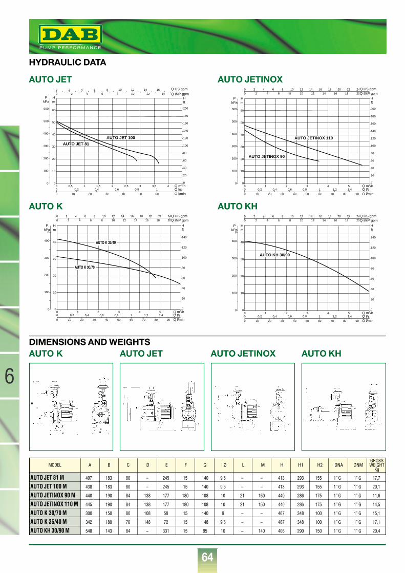
64
®
6
HYDRAULIC DATA
DIMENSIONS AND WEIGHTSAUTO K
AUTO JET 81 M 407 183 80 – 245 15 140 9,5 – – 413 293 155 1” G 1” G 17,7
AUTO JET 100 M 438 183 80 – 245 15 140 9,5 – – 413 293 155 1” G 1” G 20,1
AUTO JETINOX 90 M 440 190 84 138 177 180 108 10 21 150 440 286 175 1” G 1” G 11,6
AUTO JETINOX 110 M 445 190 84 138 177 180 108 10 21 150 440 286 175 1” G 1” G 14,5
AUTO K 30/70 M 300 150 80 108 58 15 140 9 – – 467 348 100 1” G 1” G 15,1
AUTO K 35/40 M 342 180 76 148 72 15 148 9,5 – – 467 348 100 1” G 1” G 17,1
AUTO KH 30/90 M 548 143 84 – 331 15 95 10 – 140 406 290 150 1” G 1” G 20,4
MODEL A B C D E F G I Ø L M H H1 H2 DNA DNMGROSSWEIGHT
Kg
AUTO JET AUTO JETINOX AUTO KH
AUTO JETINOX
Q m3/h0 1 2 3 4 50
10
20
30
40
50
60
0
20
40
60
80
100
120
140
160
180
200
0
00
Q l/sQ l/min
Q IMP gpmQ US gpm
0
0
0,2 0,4 0,6 0,8 1 1,2 1,4
10 20 30 40 50 60 70 80 90
Hm
Hft
PkPa
100
200
300
400
500
600
2 4 6 8 10 12 14 16 18 20 22 242 4 6 8 10 12 14 16 18 20
AUTO JETINOX 110
AUTO JETINOX 90
AUTO JET
Q m3/h0 0,5 1 1,5 2 2,5 3 3,5 40
10
20
30
40
50
0
20
40
60
80
100
120
140
160
180
200
0
00
Q l/sQ l/min
Q IMP gpmQ US gpm
0
0
0,2 0,4 0,6 0,8 1
10 20 30 40 50 60
Hm
Hft
PkPa
100
200
300
400
2 4 6 8 10 12 14 162 4 6 8 10 12 14
AUTO JET 100
AUTO JET 81
60
500
600
AUTO KH
Q m3/h0 1 2 3 4 50
10
20
30
40
0
20
40
60
80
100
120
140
0
00
Q l/sQ l/min
Q IMP gpmQ US gpm
0
0
0,2 0,4 0,6 0,8 1 1,2 1,4
10 20 30 40 50 60 70 80 90
Hm
Hft
PkPa
100
200
300
400
0
2 4 6 8 10 12 14 16 18 20 22 242 4 6 8 10 12 14 16 18 20
AUTO KH 30/90
AUTO K
Q m3/h0 1 2 3 4 50
10
20
30
40
0
20
40
60
80
100
120
140
0
00
Q l/sQ l/min
Q IMP gpmQ US gpm
0
0
0,2 0,4 0,6 0,8 1 1,2 1,4
10 20 30 40 50 60 70 80 90
Hm
Hft
PkPa
100
200
300
400
0
2 4 6 8 10 12 14 16 18 20 22 242 4 6 8 10 12 14 16 18 20
AUTO K 30/70
AUTO K 35/40
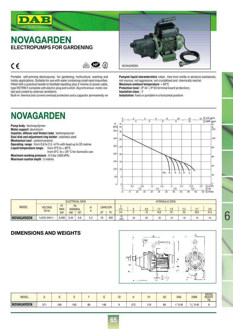
65
6
®
Q m3/h0 0,4 0,8 1,2 1,6 2 2,4 2,8 3,20
5
10
15
20
25
30
35
0
20
40
60
80
100
120
0
00
Q l/sQ l/min
Q IMP gpmQ US gpm
0
0
0,2 0,4 0,6 0,8
5 10 15 20 25 30 35 40 45 50 55
Hm
Hft
PkPa
50
100
150
200
250
300
350
2 4 6 8 10 12 142 4 6 8 10
5 4 3 2 1Hs
DIMENSIONS AND WEIGHTS
NOVAGARDEN ELECTROPUMPS FOR GARDENING
NOVAGARDEN
Portable self-priming electropump for gardening, horticulture, washing andhobby applications. Suitable for use with water containing small sand impurities.Fitted with a practical handle to facilitate handling plus 2 metres of power cable,type HO7RN-F complete with electric plug and switch. Asynchronous motor clo-sed and cooled by external ventilation.Built-in thermal and current overload protection and a capacitor permanently on
Pumped liquid characteristics :clean , free from solids or abrasive substances,not viscous, not aggressive, not crystallised and chemically neutral.Maximum ambient temperature: + 40°CProtection level : IP 44 ( IP 55 terminal board protection).Insulation class : FInstallation: fixed or portable in a horizontal position
Pump body : technopolymerMotor support: aluminiumImpeller, diffuser and Venturi tube : technopolymerSeal disk and adjustment ring holder : stainless steelMechanical seal : carbon/ceramicOperating range : from 0.6 to 2.5 m3/h with head up to 33 metresLiquid temperature range: from 0°C to + 40°C
from 0°C to + 35° C for domestic useMaximum working pressure : 4.5 bar (450 kPA)Maximum suction depth : 5 metres
MODEL
NOVAGARDEN
VOLTAGE50 Hz
P1MAXkW
InA
1x220-240 V ~ 0,490 0,44 0,6 10 450 H(m)2,3
ELECTRICAL DATA HYDRAULIC DATA
P2NOMINALkW HP
CAPACITOR
µF Vc
Qm3/h 0 0,6 1,2 1,8 2,4 2,7 3,0l/min 0 10 16,6 25 30 36,6 37,5
33 28 25 21 19 16 14
NOVAGARDEN 371 168 100 80 148 9 272 118 88 1” G-M 3/4” G-M 8
MODEL A B D F G I Ø H H1 H2 DNA DNMGROSSWEIGHT
Kg
NOVAGARDEN
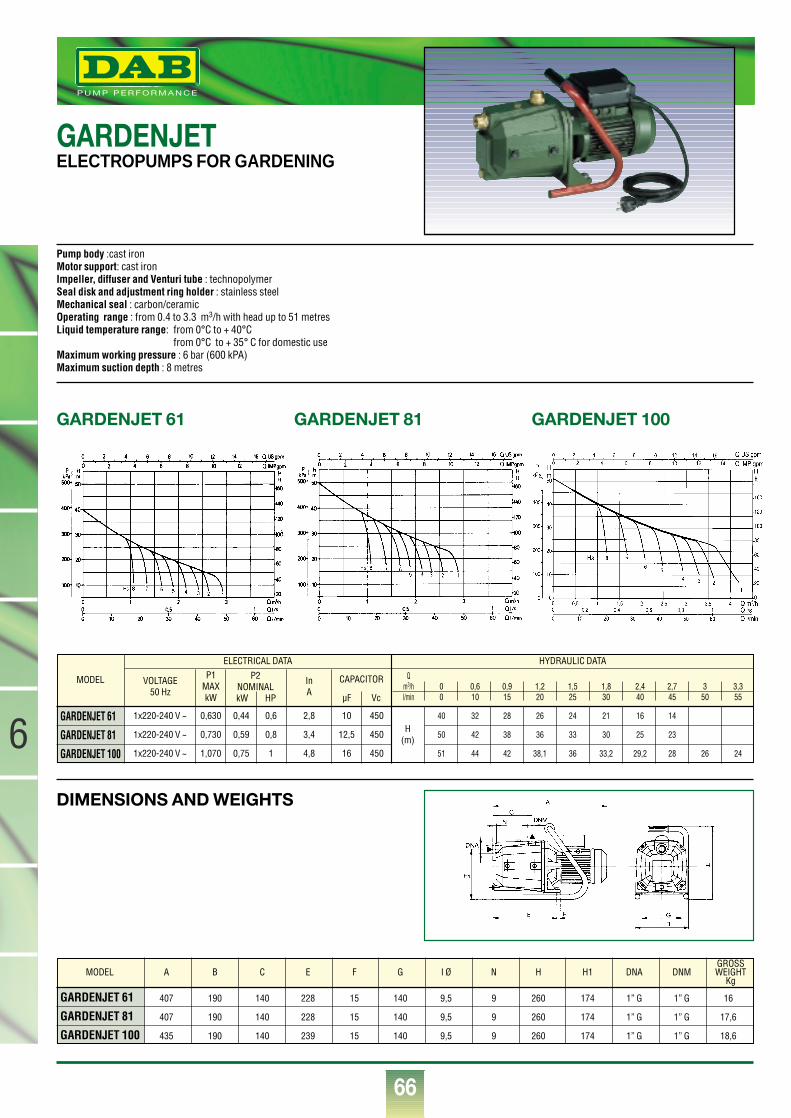
66
®
6DIMENSIONS AND WEIGHTS
GARDENJET 61 GARDENJET 81 GARDENJET 100
GARDENJETELECTROPUMPS FOR GARDENING
Pump body :cast iron Motor support: cast ironImpeller, diffuser and Venturi tube : technopolymerSeal disk and adjustment ring holder : stainless steelMechanical seal : carbon/ceramicOperating range : from 0.4 to 3.3 m3/h with head up to 51 metresLiquid temperature range: from 0°C to + 40°C
from 0°C to + 35° C for domestic useMaximum working pressure : 6 bar (600 kPA)Maximum suction depth : 8 metres
GARDENJET 61 407 190 140 228 15 140 9,5 9 260 174 1” G 1” G 16
GARDENJET 81 407 190 140 228 15 140 9,5 9 260 174 1” G 1” G 17,6
GARDENJET 100 435 190 140 239 15 140 9,5 9 260 174 1” G 1” G 18,6
MODEL A B C E F G I Ø N H H1 DNA DNMGROSSWEIGHT
Kg
MODEL
GARDENJET 61
GARDENJET 81
GARDENJET 100
VOLTAGE50 Hz
P1MAXkW
InA
1x220-240 V ~
1x220-240 V ~
1x220-240 V ~
0,630
0,730
1,070
0,44
0,59
0,75
0,6
0,8
1
10
12,5
16
450
450
450
H(m)
2,8
3,4
4,8
ELECTRICAL DATA HYDRAULIC DATA
P2NOMINALkW HP
CAPACITOR
µF Vc
Qm3/h 0 0,6 0,9 1,2 1,5 1,8 2,4 2,7 3 3,3l/min 0 10 15 20 25 30 40 45 50 55
40 32 28 26 24 21 16 14
50 42 38 36 33 30 25 23
51 44 42 38,1 36 33,2 29,2 28 26 24
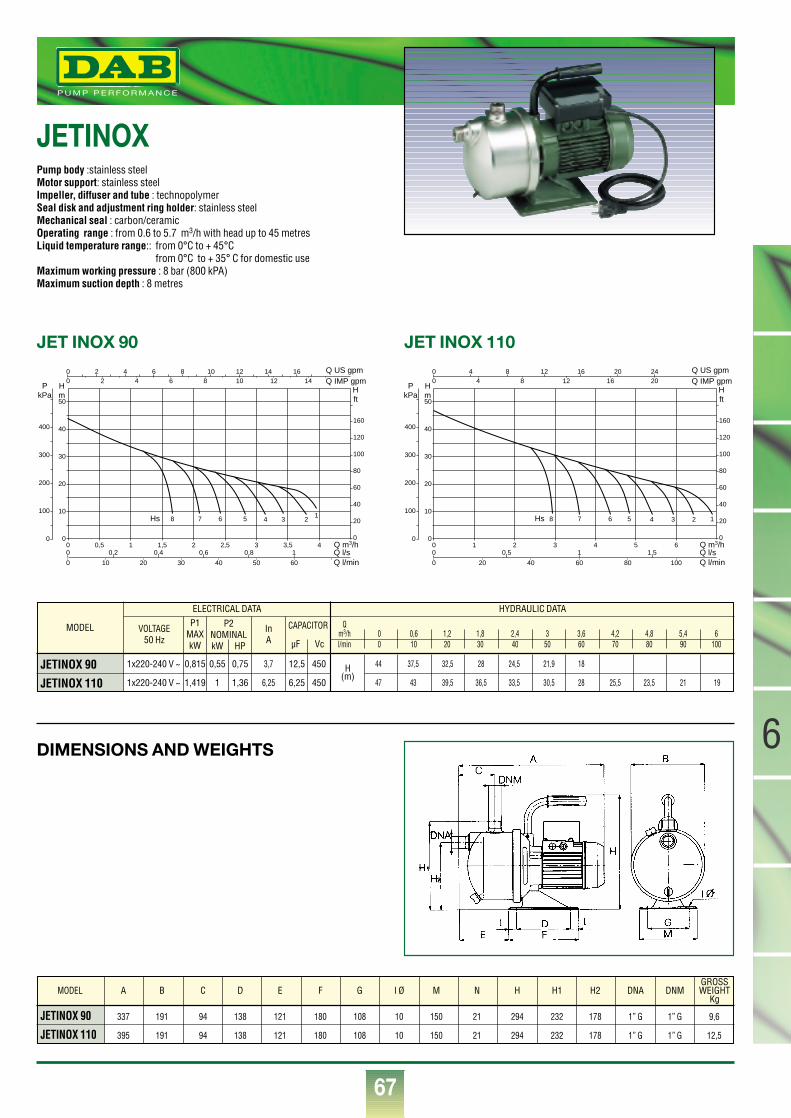
67
6
®
DIMENSIONS AND WEIGHTS
JET INOX 110
Q m3/h0 1 2 3 4 5 60
10
20
30
40
50
0
20
40
60
80
100
120
160
0
00
Q l/sQ l/min
Q IMP gpmQ US gpm
0
0
0,5 1 1,5
20 40 60 80 100
Hm
Hft
PkPa
100
200
300
400
4 8 12 16 20 244 8 12 16 20
Hs 8 7 6 5 4 3 2 1
JET INOX 90
Q m3/h0 0,5 1 1,5 2 2,5 3 3,5 40
10
20
30
40
50
0
20
40
60
80
100
120
160
0
00
Q l/sQ l/min
Q IMP gpmQ US gpm
0
0
0,2 0,4 0,6 0,8 1
10 20 30 40 50 60
Hm
Hft
PkPa
100
200
300
400
2 4 6 8 10 12 14 162 4 6 8 10 12 14
Hs 8 7 6 5 4 3 21
JETINOXPump body :stainless steel Motor support: stainless steelImpeller, diffuser and tube : technopolymerSeal disk and adjustment ring holder: stainless steel Mechanical seal : carbon/ceramicOperating range : from 0.6 to 5.7 m3/h with head up to 45 metresLiquid temperature range:: from 0°C to + 45°C
from 0°C to + 35° C for domestic useMaximum working pressure : 8 bar (800 kPA)Maximum suction depth : 8 metres
MODEL
JETINOX 90
JETINOX 110
VOLTAGE50 Hz
P1MAXkW
InA
1x220-240 V ~
1x220-240 V ~
0,815
1,419
0,55
1
0,75
1,36
12,5
6,25
450
450H
(m)3,7
6,25
ELECTRICAL DATA HYDRAULIC DATA
P2NOMINALkW HP
CAPACITOR
µF Vc
Qm3/h 0 0,6 1,2 1,8 2,4 3 3,6 4,2 4,8 5,4 6l/min 0 10 20 30 40 50 60 70 80 90 100
44 37,5 32,5 28 24,5 21,9 18
47 43 39,5 36,5 33,5 30,5 28 25,5 23,5 21 19
JETINOX 90 337 191 94 138 121 180 108 10 150 21 294 232 178 1” G 1” G 9,6
JETINOX 110 395 191 94 138 121 180 108 10 150 21 294 232 178 1” G 1” G 12,5
MODEL A B C D E F G I Ø M N H H1 H2 DNA DNMGROSSWEIGHT
Kg
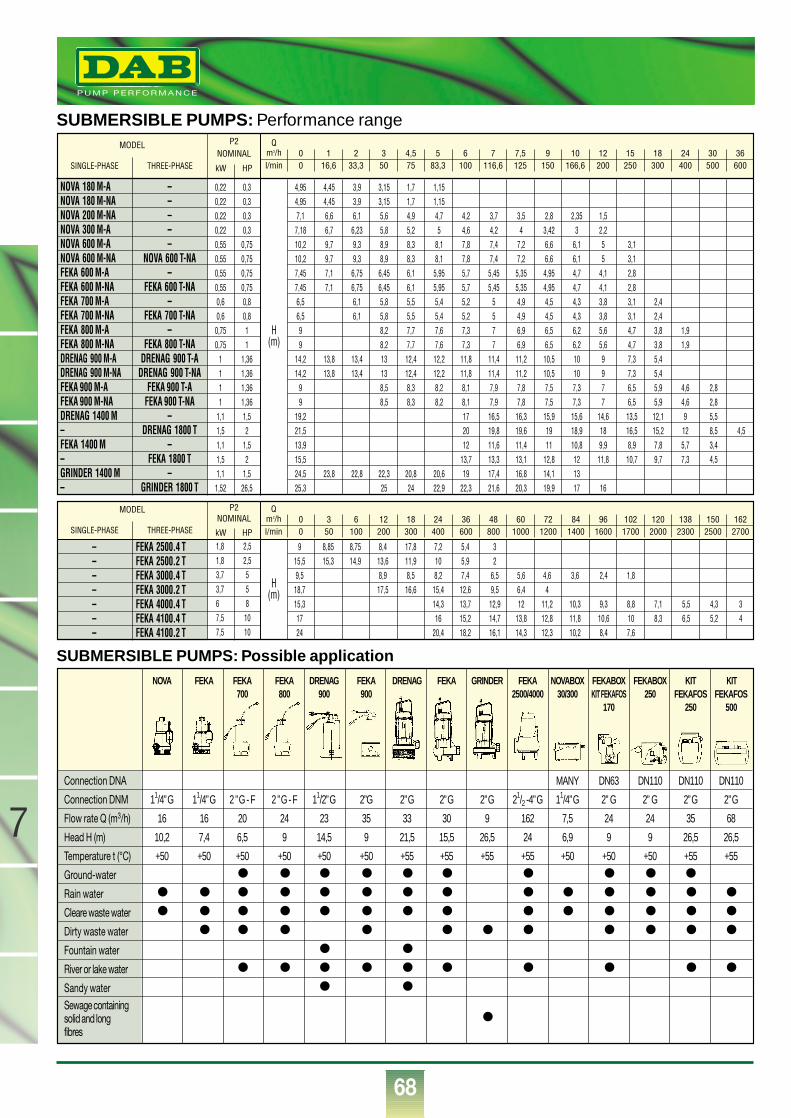
68
®
SUBMERSIBLE PUMPS: Performance range
SUBMERSIBLE PUMPS: Possible application
Sewage containingsolid and long ●
fibres
NOVA FEKA FEKA FEKA DRENAG FEKA DRENAG FEKA GRINDER FEKA NOVABOX FEKABOX FEKABOX KIT KIT700 800 900 900 2500/4000 30/300 KIT FEKAFOS 250 FEKAFOS FEKAFOS
170 250 500
Connection DNA MANY DN63 DN110 DN110 DN110
Connection DNM 11/4”G 11/4”G 2 ”G - F 2 ”G - F 11/2”G 2”G 2”G 2”G 2”G 21/2 -4”G 11/4”G 2” G 2” G 2”G 2”G
Flow rate Q (m3/h) 16 16 20 24 23 35 33 30 9 162 7,5 24 24 35 68
Head H (m) 10,2 7,4 6,5 9 14,5 9 21,5 15,5 26,5 24 6,9 9 9 26,5 26,5
Temperature t (°C) +50 +50 +50 +50 +50 +50 +55 +55 +55 +55 +50 +50 +50 +55 +55
Ground-water ● ● ● ● ● ● ● ● ● ●
Rain water ● ● ● ● ● ● ● ● ● ● ● ● ● ●
Cleare waste water ● ● ● ● ● ● ● ● ● ● ● ● ● ●
Dirty waste water ● ● ● ● ● ● ● ● ● ● ●
Fountain water ● ●
River or lake water ● ● ● ● ● ● ● ● ● ●
Sandy water ● ●
MODEL
SINGLE-PHASE THREE-PHASE
MODEL
SINGLE-PHASE THREE-PHASE
P2NOMINAL
kW HP
P2NOMINAL
kW HP
Qm3/hl/min
00
116,6
233,3
350
4,575
583,3
6100
7116,6
7,5125
9150
10166,6
12200
15250
18300
24400
30500
36600
– FEKA 2500.4 T– FEKA 2500.2 T– FEKA 3000.4 T– FEKA 3000.2 T– FEKA 4000.4 T– FEKA 4100.4 T– FEKA 4100.2 T
H(m)
H(m)
Qm3/hl/min
00
350
6100
12200
18300
24400
36600
48800
601000
721200
841400
961600
1021700
1202000
1382300
1502500
1622700
9 8,85 8,75 8,4 17,8 7,2 5,4 315,5 15,3 14,9 13,6 11,9 10 5,9 29,5 8,9 8,5 8,2 7,4 6,5 5,6 4,6 3,6 2,4 1,8
18,7 17,5 16,6 15,4 12,6 9,5 6,4 415,3 14,3 13,7 12,9 12 11,2 10,3 9,3 8,8 7,1 5,5 4,3 317 16 15,2 14,7 13,8 12,8 11,8 10,6 10 8,3 6,5 5,2 424 20,4 18,2 16,1 14,3 12,3 10,2 8,4 7,6
1,8 2,51,8 2,53,7 53,7 56 87,5 107,5 10
NOVA 180 M-A – 0,22 0,3 4,95 4,45 3,9 3,15 1,7 1,15NOVA 180 M-NA – 0,22 0,3 4,95 4,45 3,9 3,15 1,7 1,15NOVA 200 M-NA – 0,22 0,3 7,1 6,6 6,1 5,6 4,9 4,7 4,2 3,7 3,5 2,8 2,35 1,5NOVA 300 M-A – 0,22 0,3 7,18 6,7 6,23 5,8 5,2 5 4,6 4,2 4 3,42 3 2,2NOVA 600 M-A – 0,55 0,75 10,2 9,7 9,3 8,9 8,3 8,1 7,8 7,4 7,2 6,6 6,1 5 3,1NOVA 600 M-NA NOVA 600 T-NA 0,55 0,75 10,2 9,7 9,3 8,9 8,3 8,1 7,8 7,4 7,2 6,6 6,1 5 3,1FEKA 600 M-A – 0,55 0,75 7,45 7,1 6,75 6,45 6,1 5,95 5,7 5,45 5,35 4,95 4,7 4,1 2,8FEKA 600 M-NA FEKA 600 T-NA 0,55 0,75 7,45 7,1 6,75 6,45 6,1 5,95 5,7 5,45 5,35 4,95 4,7 4,1 2,8FEKA 700 M-A – 0,6 0,8 6,5 6,1 5,8 5,5 5,4 5,2 5 4,9 4,5 4,3 3,8 3,1 2,4FEKA 700 M-NA FEKA 700 T-NA 0,6 0,8 6,5 6,1 5,8 5,5 5,4 5,2 5 4,9 4,5 4,3 3,8 3,1 2,4FEKA 800 M-A – 0,75 1 9 8,2 7,7 7,6 7,3 7 6,9 6,5 6,2 5,6 4,7 3,8 1,9FEKA 800 M-NA FEKA 800 T-NA 0,75 1 9 8,2 7,7 7,6 7,3 7 6,9 6,5 6,2 5,6 4,7 3,8 1,9DRENAG 900 M-A DRENAG 900 T-A 1 1,36 14,2 13,8 13,4 13 12,4 12,2 11,8 11,4 11,2 10,5 10 9 7,3 5,4DRENAG 900 M-NA DRENAG 900 T-NA 1 1,36 14,2 13,8 13,4 13 12,4 12,2 11,8 11,4 11,2 10,5 10 9 7,3 5,4FEKA 900 M-A FEKA 900 T-A 1 1,36 9 8,5 8,3 8,2 8,1 7,9 7,8 7,5 7,3 7 6,5 5,9 4,6 2,8FEKA 900 M-NA FEKA 900 T-NA 1 1,36 9 8,5 8,3 8,2 8,1 7,9 7,8 7,5 7,3 7 6,5 5,9 4,6 2,8DRENAG 1400 M – 1,1 1,5 19,2 17 16,5 16,3 15,9 15,6 14,6 13,5 12,1 9 5,5– DRENAG 1800 T 1,5 2 21,5 20 19,8 19,6 19 18,9 18 16,5 15,2 12 8,5 4,5FEKA 1400 M – 1,1 1,5 13,9 12 11,6 11,4 11 10,8 9,9 8,9 7,8 5,7 3,4– FEKA 1800 T 1,5 2 15,5 13,7 13,3 13,1 12,8 12 11,8 10,7 9,7 7,3 4,5GRINDER 1400 M – 1,1 1,5 24,5 23,8 22,8 22,3 20,8 20,6 19 17,4 16,8 14,1 13– GRINDER 1800 T 1,52 26,5 25,3 25 24 22,9 22,3 21,6 20,3 19,9 17 16
7
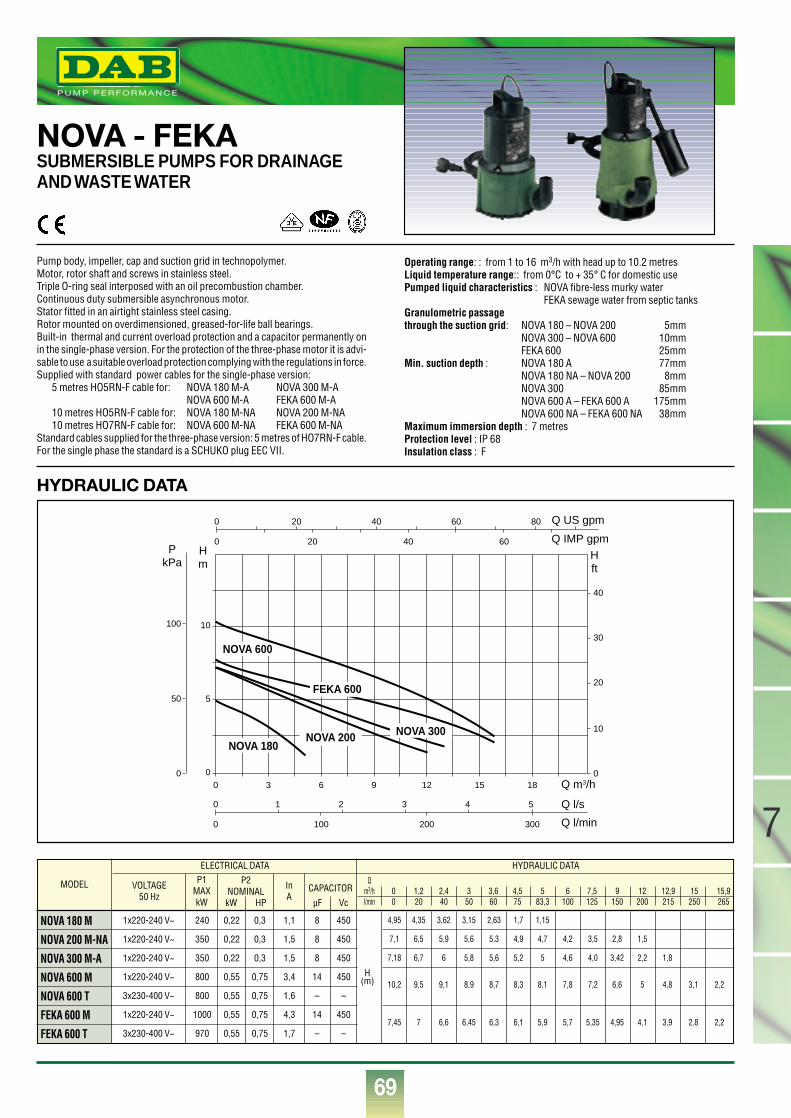
69
7
®
NOVA - FEKA SUBMERSIBLE PUMPS FOR DRAINAGEAND WASTE WATER
Pump body, impeller, cap and suction grid in technopolymer.Motor, rotor shaft and screws in stainless steel.Triple O-ring seal interposed with an oil precombustion chamber. Continuous duty submersible asynchronous motor.Stator fitted in an airtight stainless steel casing.Rotor mounted on overdimensioned, greased-for-life ball bearings.Built-in thermal and current overload protection and a capacitor permanently onin the single-phase version. For the protection of the three-phase motor it is advi-sable to use a suitable overload protection complying with the regulations in force.Supplied with standard power cables for the single-phase version:
5 metres HO5RN-F cable for: NOVA 180 M-A NOVA 300 M-ANOVA 600 M-A FEKA 600 M-A
10 metres HO5RN-F cable for: NOVA 180 M-NA NOVA 200 M-NA10 metres HO7RN-F cable for: NOVA 600 M-NA FEKA 600 M-NA
Standard cables supplied for the three-phase version: 5 metres of HO7RN-F cable.For the single phase the standard is a SCHUKO plug EEC VII.
Operating range: : from 1 to 16 m3/h with head up to 10.2 metresLiquid temperature range:: from 0°C to + 35° C for domestic usePumped liquid characteristics : NOVA fibre-less murky water
FEKA sewage water from septic tanksGranulometric passagethrough the suction grid: NOVA 180 – NOVA 200 5mm
NOVA 300 – NOVA 600 10mmFEKA 600 25mm
Min. suction depth : NOVA 180 A 77mmNOVA 180 NA – NOVA 200 8mmNOVA 300 85mmNOVA 600 A – FEKA 600 A 175mmNOVA 600 NA – FEKA 600 NA 38mm
Maximum immersion depth : 7 metresProtection level : IP 68Insulation class : F
MODEL
NOVA 180 M
NOVA 200 M-NA
NOVA 300 M-A
NOVA 600 M
NOVA 600 T
FEKA 600 M
FEKA 600 T
VOLTAGE50 Hz
P1MAXkW
InA
1x220-240 V~
1x220-240 V~
1x220-240 V~
1x220-240 V~
3x230-400 V~
1x220-240 V~
3x230-400 V~
240
350
350
800
800
1000
970
0,22
0,22
0,22
0,55
0,55
0,55
0,55
8
8
8
14
–
14
–
450
450
450
450
–
450
–
0,3
0,3
0,3
0,75
0,75
0,75
0,75
H(m)
1,1
1,5
1,5
3,4
1,6
4,3
1,7
ELECTRICAL DATA HYDRAULIC DATA
P2NOMINALkW HP
CAPACITOR
µF Vc
Qm3/h 0 1,2 2,4 3 3,6 4,5 5 6 7,5 9 12 12,9 15 15,9l/min 0 20 40 50 60 75 83,3 100 125 150 200 215 250 265
4,95 4,35 3,62 3,15 2,63 1,7 1,15
7,1 6,5 5,9 5,6 5,3 4,9 4,7 4,2 3,5 2,8 1,5
7,18 6,7 6 5,8 5,6 5,2 5 4,6 4,0 3,42 2,2 1,8
10,2 9,5 9,1 8,9 8,7 8,3 8,1 7,8 7,2 6,6 5 4,8 3,1 2,2
7,45 7 6,6 6,45 6,3 6,1 5,9 5,7 5,35 4,95 4,1 3,9 2,8 2,2
Q m3/h
Q l/s
Q l/min
Q IMP gpm
Q US gpm
Hm
Hft
PkPa
0 3 6 9 12 15 18
0
0
00
5
10
50
100
1 2 3 4 5
100 200 300
0
0 20 40 60 80
20 40 60
0
10
20
30
40
NOVA 600
NOVA 180NOVA 200 NOVA 300
FEKA 600
HYDRAULIC DATA
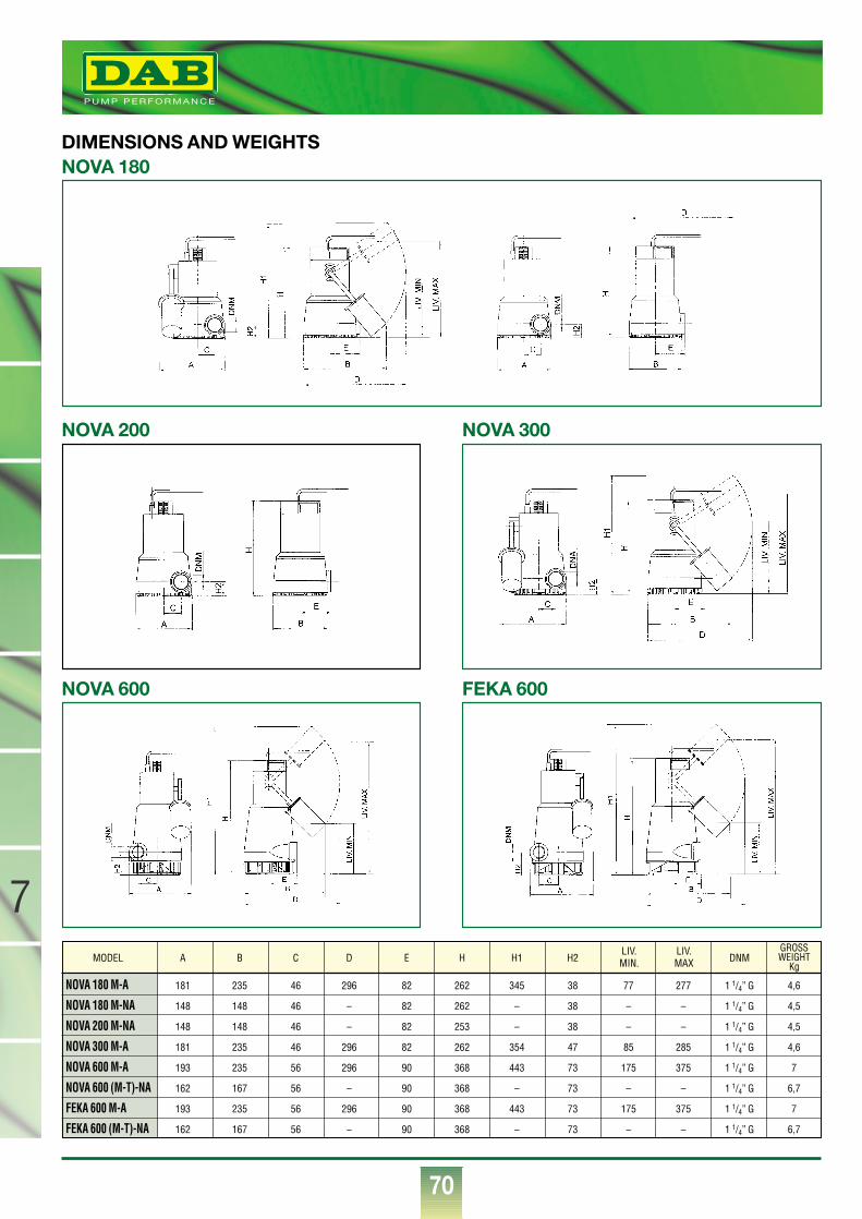
70
®
7
NOVA 180 M-A 181 235 46 296 82 262 345 38 77 277 1 1/4” G 4,6
NOVA 180 M-NA 148 148 46 – 82 262 – 38 – – 1 1/4” G 4,5
NOVA 200 M-NA 148 148 46 – 82 253 – 38 – – 1 1/4” G 4,5
NOVA 300 M-A 181 235 46 296 82 262 354 47 85 285 1 1/4” G 4,6
NOVA 600 M-A 193 235 56 296 90 368 443 73 175 375 1 1/4” G 7
NOVA 600 (M-T)-NA 162 167 56 – 90 368 – 73 – – 1 1/4” G 6,7
FEKA 600 M-A 193 235 56 296 90 368 443 73 175 375 1 1/4” G 7
FEKA 600 (M-T)-NA 162 167 56 – 90 368 – 73 – – 1 1/4” G 6,7
MODEL A B C D E H H1 H2 DNMGROSSWEIGHT
KgLIV.MAX
LIV.MIN.
NOVA 180DIMENSIONS AND WEIGHTS
NOVA 300
FEKA 600
NOVA 200
NOVA 600
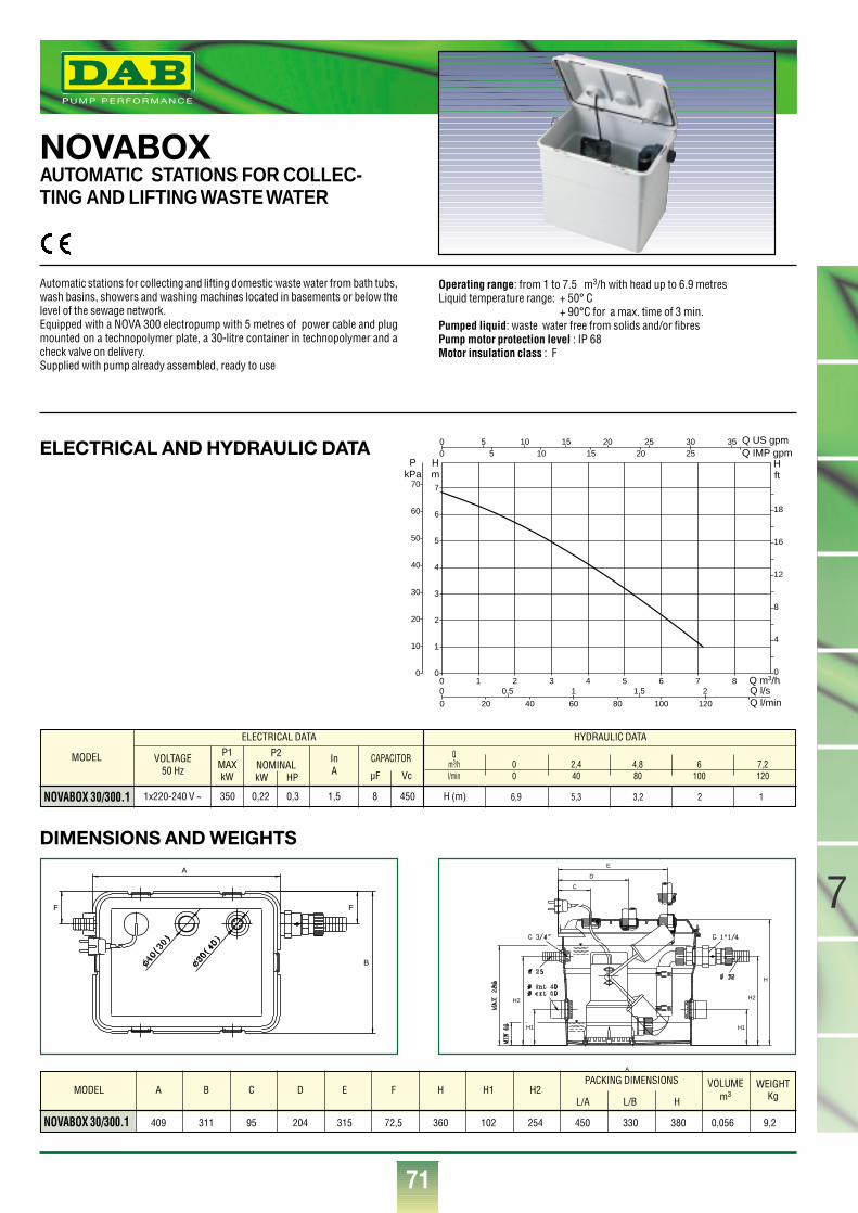
71
7
®
Q m3/h0 1 2 3 4 5 6 7 80
1
2
3
4
5
6
7
0
4
8
12
16
18
0
00
Q l/sQ l/min
Q IMP gpmQ US gpm
0
0
0,5 1 1,5 2
20 40 60 80 100 120
Hm
Hft
PkPa
10
20
30
40
50
60
70
5 10 15 20 25 30 355 10 15 20 25ELECTRICAL AND HYDRAULIC DATA
DIMENSIONS AND WEIGHTS
NOVABOX AUTOMATIC STATIONS FOR COLLEC-TING AND LIFTING WASTE WATER
Automatic stations for collecting and lifting domestic waste water from bath tubs,wash basins, showers and washing machines located in basements or below thelevel of the sewage network.Equipped with a NOVA 300 electropump with 5 metres of power cable and plugmounted on a technopolymer plate, a 30-litre container in technopolymer and acheck valve on delivery.Supplied with pump already assembled, ready to use
Operating range: from 1 to 7.5 m3/h with head up to 6.9 metresLiquid temperature range: + 50° C
+ 90°C for a max. time of 3 min.Pumped liquid: waste water free from solids and/or fibresPump motor protection level : IP 68Motor insulation class : F
MODEL
NOVABOX 30/300.1
VOLTAGE50 Hz
P1MAXkW
InA
1x220-240 V ~ 350 0,22 0,3 8 450 H (m)1,5
ELECTRICAL DATA HYDRAULIC DATA
P2NOMINALkW HP
CAPACITOR
µF Vc
Qm3/h 0 2,4 4,8 6 7,2l/min 0 40 80 100 120
6,9 5,3 3,2 2 1
NOVABOX 30/300.1 409 311 95 204 315 72,5 360 102 254 450 330 380 0,056 9,2
MODEL A B C D E F H H1 H2PACKING DIMENSIONS WEIGHT
KgVOLUME
m3L/A L/B H
F F
B
A
A
E
D
C
H1
H2
H1
H2
H
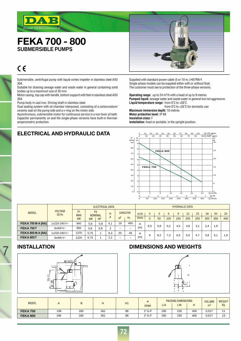
72
7
®®
ELECTRICAL AND HYDRAULIC DATA
INSTALLATION DIMENSIONS AND WEIGHTS
FEKA 700 - 800SUBMERSIBLE PUMPS
Submersible, centrifugal pump with liquid vortex impeller in stainless steel AISI304.Suitable for draining sewage water and waste water in general containing solidbodies up to a maximum size of 35 mm.Motor casing, top cap with handle, bottom support with feet in stainless steel AISI304.Pump body in cast iron. Driving shaft in stainless steel.Dual sealing system with oil chamber interposed, consisting of a carborundum/ceramic seal on the pump side and a v-ring on the motor side.Asynchronous, submersible motor for continuous service in a non toxic oil bath.Capacitor permanently on and the single-phase versions have built-in thermal-amperometric protection.
Supplied with standard power cable (5 or 10 m.) H07RN-F.Single-phase models can be supplied either with or without float.The customer must see to protection of the three-phase versions.
Operating range: up to 24 m3/h with a head of up to 9 metres.Pumped liquid: sewage water and waste water in general but not aggressive.Liquid temperature range: from 0˚C to +50˚C
from 0˚C to +35˚C for domestic use Maximum immersion depth: 10 metresMotor protection level: IP 68Insulation class: FInstallation: fixed or portable, in the upright position.
FEKA 800FEKA 700
PACKING DIMENSIONSL/A L/B H
MODEL VOLTAGE50 Hz
1x220-240 V~
3x400 V~
1x220-240 V~
3x400 V~
P1MAXkW
940
950
1370
1220
P2NOMINAL
kW HP
0,6 0,8
0,6 0,8
0,75 1
0,75 1
CAPACITOR
µF Vc
16 450
– –
20 45
– –
ELECTRICAL DATA HYDRAULIC DATA
H(m)
H(m)
m3/hl/min
9 8,2 7,3 6,5 5,6 4,7 3,8 3,1 1,9
6,5 5,8 5,2 4,5 3,8 3,1 2,4 1,9
0 50 100 150 200 250 300 350 400
0 3 6 9 12 15 18 20 24
MODEL VOLUMEm3
WEIGHTKg
ø
DNM
InA
4,1
2
6,3
2,2
A B H H1
196 180 361 88 2” G-F 190 230 400 0,017 11
196 180 361 88 2” G-F 190 230 400 0,017 13
FEKA 700 M-A (NA)
FEKA 700 TFEKA 800 M-A (NA)FEKA 800 T
0
1
2
3
4
5
6
7
8
9
0
Hm
PkPa
10
20
30
40
50
60
70
80
90
0
5
10
15
20
25
30
Hft
0
0
Q IMP gpmQ US gpm10 20 30 40 50 60 70 80 90 100
10 20 30 40 50 60 70 80 90
0
0
4 8 12 16 20 24
0
Q m3/hQ l/s
Q l/min1 2 3 4 5 6 7
50 100 150 200 250 300 350 400
FEKA 800
FEKA 700
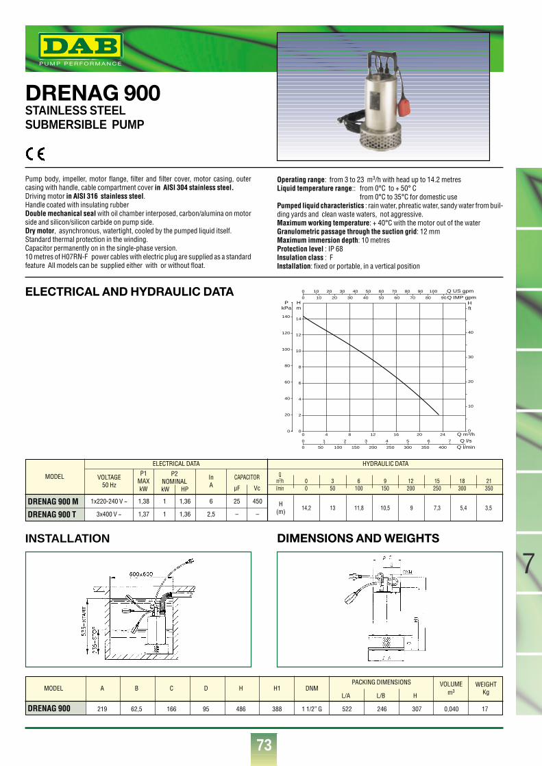
73
7
®
ELECTRICAL AND HYDRAULIC DATA
INSTALLATION DIMENSIONS AND WEIGHTS
DRENAG 900STAINLESS STEEL SUBMERSIBLE PUMP
Pump body, impeller, motor flange, filter and filter cover, motor casing, outercasing with handle, cable compartment cover in AISI 304 stainless steel.Driving motor in AISI 316 stainless steel.Handle coated with insulating rubberDouble mechanical seal with oil chamber interposed, carbon/alumina on motorside and silicon/silicon carbide on pump side.Dry motor, asynchronous, watertight, cooled by the pumped liquid itself.Standard thermal protection in the winding.Capacitor permanently on in the single-phase version.10 metres of H07RN-F power cables with electric plug are supplied as a standardfeature All models can be supplied either with or without float.
Operating range: from 3 to 23 m3/h with head up to 14.2 metresLiquid temperature range:: from 0°C to + 50° C
from 0°C to 35°C for domestic usePumped liquid characteristics : rain water, phreatic water, sandy water from buil-ding yards and clean waste waters, not aggressive.Maximum working temperature: + 40°C with the motor out of the waterGranulometric passage through the suction grid: 12 mmMaximum immersion depth: 10 metresProtection level : IP 68Insulation class : FInstallation: fixed or portable, in a vertical position
MODEL
DRENAG 900 M
DRENAG 900 T
VOLTAGE50 Hz
P1MAXkW
InA
1x220-240 V ~
3x400 V ~
1,38
1,37
1
1
1,36
1,36
25
–
450
–
H(m)
6
2,5
ELECTRICAL DATA HYDRAULIC DATA
P2NOMINALkW HP
CAPACITOR
µF Vc
Qm3/h 0 3 6 9 12 15 18 21l/min 0 50 100 150 200 250 300 350
14,2 13 11,8 10,5 9 7,3 5,4 3,5
DRENAG 900 219 62,5 166 95 486 388 1 1/2” G 522 246 307 0,040 17
MODEL A B C D H H1 DNMPACKING DIMENSIONS WEIGHT
KgVOLUME
m3L/A L/B H
0
0
0
0
4 8 12 16 20 24
0
Q m3/h
Q IMP gpmQ US gpm
Q l/sQ l/min
0
2
4
6
8
10
12
14
0
Hm
PkPa
1 2 3 4 5 6 7
50 100 150 200 250 300 350 400
20
40
60
80
100
120
140
0
10
20
30
40
Hft
10 20 30 40 50 60 70 80 90 100
10 20 30 40 50 60 70 80 90
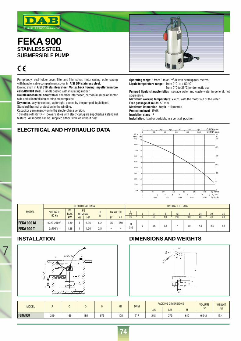
74
®
7
ELECTRICAL AND HYDRAULIC DATA
INSTALLATION DIMENSIONS AND WEIGHTS
FEKA 900STAINLESS STEEL SUBMERSIBLE PUMP
Pump body, seal holder cover, filter and filter cover, motor casing, outer casingwith handle, cable compartment cover in AISI 304 stainless steel.Driving shaft in AISI 316 stainless steel. Vortex back flowing impeller in microcast AISI 304 steel. Handle coated with insulating rubber.Double mechanical seal with oil chamber interposed, carbon/alumina on motorside and silicon/silicon carbide on pump side.Dry motor, asynchronous, watertight, cooled by the pumped liquid itself.Standard thermal protection in the winding.Capacitor permanently on in the single-phase version.10 metres of H07RN-F power cables with electric plug are supplied as a standardfeature. All models can be supplied either with or without float.
Operating range: : from 3 to 35 m3/h with head up to 9 metresLiquid temperature range:: from 0°C to + 50° C
from 0°C to 35°C for domestic usePumped liquid characteristics : sewage water and waste water in general, notaggressive.Maximum working temperature: + 40°C with the motor out of the waterFree passage of solids: 50 mmMaximum immersion depth : 10 metresProtection level : IP 68Insulation class : FInstallation: fixed or portable, in a vertical position
MODEL
FEKA 900 M
FEKA 900 T
VOLTAGE50 Hz
P1MAXkW
InA
1x220-240 V ~
3x400 V ~
1,39
1,38
1
1
1,36
1,36
25
–
450
–
H(m)
6,2
2,5
ELECTRICAL DATA HYDRAULIC DATA
P2NOMINALkW HP
CAPACITOR
µF Vc
Qm3/h 0 3 6 12 18 24 30 35l/min 0 50 100 200 300 400 500 600
9 8,5 8,1 7 5,9 4,6 2,8 1,4
FEKA 900 219 166 185 575 105 2” F 248 279 612 0,042 17,4
A C D H H1 DNMPACKING DIMENSIONS WEIGHT
KgVOLUME
m3L/A L/B H
MODEL
0
0
0
0
5 10 15 20 25 30
0
Q m3/h
Q IMP gpmQ US gpm
Q l/sQ l/min
0
1
2
3
4
5
6
7
8
9
0
Hm
PkPa
1 2 3 4 5 6 7 8 9
100 200 300 400 500
10
20
30
40
50
60
70
80
90
0
5
10
15
20
25
30
Hft
20 40 60 80 100 120
20 40 60 80 100
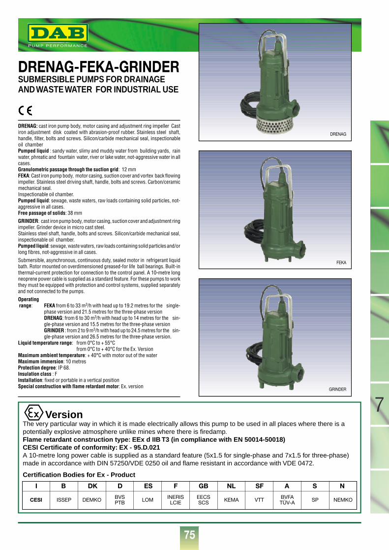
75
7
®
DRENAG-FEKA-GRINDER SUBMERSIBLE PUMPS FOR DRAINAGEAND WASTE WATER FOR INDUSTRIAL USE
DRENAG: cast iron pump body, motor casing and adjustment ring impeller Castiron adjustment disk coated with abrasion-proof rubber. Stainless steel shaft,handle, filter, bolts and screws. Silicon/carbide mechanical seal, inspectionableoil chamberPumped liquid : sandy water, slimy and muddy water from building yards, rainwater, phreatic and fountain water, river or lake water, not-aggressive water in allcases.Granulometric passage through the suction grid: 12 mm FEKA: Cast iron pump body, motor casing, suction cover and vortex back flowingimpeller. Stainless steel driving shaft, handle, bolts and screws. Carbon/ceramicmechanical seal.Inspectionable oil chamber.Pumped liquid: sewage, waste waters, raw loads containing solid particles, not-aggressive in all cases.Free passage of solids: 38 mmGRINDER: cast iron pump body, motor casing, suction cover and adjustment ringimpeller. Grinder device in micro cast steel.Stainless steel shaft, handle, bolts and screws. Silicon/carbide mechanical seal,inspectionable oil chamber.Pumped liquid: sewage, waste waters, raw loads containing solid particles and/orlong fibres, not-aggressive in all cases.Submersible, asynchronous, continuous duty, sealed motor in refrigerant liquidbath. Rotor mounted on overdimensioned greased-for life ball bearings. Built-inthermal-current protection for connection to the control panel. A 10-metre longneoprene power cable is supplied as a standard feature. For these pumps to workthey must be equipped with protection and control systems, supplied separatelyand not connected to the pumps.Operatingrange: FEKA from 6 to 33 m3/h with head up to 19.2 metres for the single-
phase version and 21.5 metres for the three-phase versionDRENAG: from 6 to 30 m3/h with head up to 14 metres for the sin-gle-phase version and 15.5 metres for the three-phase versionGRINDER : from 2 to 9 m3/h with head up to 24.5 metres for the sin-gle-phase version and 26.5 metres for the three-phase version.
Liquid temperature range: from 0°C to + 55°Cfrom 0°C to + 40°C for the Ex. Version
Maximum ambient temperature: + 40°C with motor out of the waterMaximum immersion: 10 metresProtection degree: IP 68.Insulation class : FInstallation: fixed or portable in a vertical positionSpecial construction with flame retardant motor: Ex. version
VersionThe very particular way in which it is made electrically allows this pump to be used in all places where there is apotentially explosive atmosphere unlike mines where there is firedamp.Flame retardant construction type: EEx d IIB T3 (in compliance with EN 50014-50018)CESI Certificate of conformity: EX - 95.D.021A 10-metre long power cable is supplied as a standard feature (5x1.5 for single-phase and 7x1.5 for three-phase)made in accordance with DIN 57250/VDE 0250 oil and flame resistant in accordance with VDE 0472.
Certification Bodies for Ex - Product
I B DK D ES F GB NL SF A S N
CESI ISSEP DEMKO BVSPTB LOM INERIS
LCIEEECSSCS KEMA VTT BVFA
TÜV-A SP NEMKO
DRENAG
FEKA
GRINDER
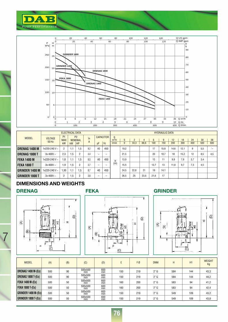
76
®
7
MODEL
DRENAG 1400 M
DRENAG 1800 T
FEKA 1400 M
FEKA 1800 T
GRINDER 1400 M
GRINDER 1800 T
VOLTAGE50 Hz
P1MAXkW
InA
1x220-240 V ~
3x 400V ~
1x220-240 V ~
3x 400V ~
1x220-240 V ~
3x 400V ~
2
2,3
1,8
1,9
1,95
2
1,1
1,5
1,1
1,5
1,1
1,5
1,5
2
1,5
2
1,5
2
40
–
40
–
40
–
450
–
450
–
450
–
H(m)
9,2
4,4
8,5
3,7
8,7
3,8
ELECTRICAL DATA HYDRAULIC DATA
P2NOMINAL
kW HP
CAPACITOR
µF Vc
Qm3/h 0 2 4 6 9 12 18 24 30 36l/min 0 33,3 66,6 100 150 200 300 400 500 600
19,2 17 15,8 14,6 12,1 9 5,5 ´–
21,5 20 18,7 18 15,2 12 8,5 4,5
13,9 12 11 9,9 7,8 5,7 3,4
15,5 13,7 13 11,8 9,7 7,3 4,5
24,5 22,8 21 19 14,1
26,5 25 23,5 21,6 17
Q m3/h
Q l/sQ l/min
Q IMP gpmQ US gpm
Hm
Hft
PkPa
0 3 6 9 12 15 18 21 24 27 30 33 36
0
0
00
5
10
15
20
25
50
100
150
200
250
1 2 3 4 5 6 7 8 9 10
100 200 300 400 500 600
0
0 20 40 60 80 100 120 140
20 40 60 80 100 120
0
10
20
30
40
50
60
70
80
90
DRENAG 1400
DRENAG 1800
FEKA 1800
GRINDER 1800
FEKA 1400
GRINDER 1400
DIMENSIONS AND WEIGHTSDRENAG FEKA GRINDER
DRENAG 1400 M-(Ex) 500 90 150 219 2” G 584 144 43,3
DRENAG 1800 T-(Ex) 500 90 150 219 2” G 584 144 44,2
FEKA 1400 M-(Ex) 500 50 160 200 2” G 583 94 41,2
FEKA 1800 T-(Ex) 500 50 160 200 2” G 583 94 42,4
GRINDER 1400 M-(Ex) 500 50 150 219 2” G 549 109 43,2
GRINDER 1800 T-(Ex) 500 50 150 219 2” G 549 109 43,8
MODEL (A) (B) (C) (D) E F Ø DNM H H1 WEIGHTKg
500x500min
500x500min
500x500min
500x500min
500x500min
500x500min
600min600min600min600min600min600min

77
7
®
ELECTRIC PANELS FOR THE PROTECTION AND CONTROL OF SUBMERSIBLE PUMPS FOR INDUSTRIAL USE
Electric control panels for the protection and automatic and manual operation(model MDN) of single-phase and three-phase electric pumps with float/s, in sin-gle installations or in pairs. Ex versions suitable for electric pumps with explosion-proof motors. Floats must be ordered separately. The panels are supplied mounted in a flame-proof thermoplastic cabinet and apainted metal cabinet for models A ED...and A E2D..., complete with wall brackets.Ambient inverters are fitted on panels for pumps installed in pairs. Operating tem-perature range: -10°C +40°C.Built to EN 60204-1 and EN 60439-1Level of protection: IP 55 - Models A ED...and A E2D...IP 44 or IP 65
Main electric components:-modular isolator for the power input line with padlockable door handle(three-phase version);
-self-protected transformer for 24V powering of external commands;-manually resettable overload cut-out;-terminals for connecting electric pump/s and float/s (or pressure switches);-terminals for connecting a remote acoustic or luminous alarm;-switch for man - 0 - out operation (three-phase version);-button for manual pump operation;-green LED’s indicating that the pumps are working and red LED’s indicating thatthe thermal-current protection device has cut in (three-phase version);
-automatic device for increasing starting current (mod. ED 3M Hs)
MDN 225 168 196 – 148 2,1
ED 1,3-3 M 350 245 270 300 190 5,6
ED 3M Hs 350 335 270 390 190 6,9
ED2 2,6-6 M 345 335 270 390 230 8 - 8,5
TD 1,5 M Ex 325 242 255 310 183 10
TD 1,5 M Hs Ex 325 312 255 380 183 11,8
ED 1-1,5-2,5 T 350 245 270 300 230 5,6
E2D 2-3-5 T 345 335 270 390 230 8 - 8,1
TD 2 T Ex 325 242 255 310 183 10
A ED 2,5-5-15 T 350 – 300 390 200 11
A E2D 5-10-30 T 450 – 400 590 240 24
A B C D E
DIMENSIONS GROSS WEIGHTKgMODEL
DIMENSIONS AND WEIGHTS
TECHNICAL DATA
MODEL VOLTAGE50 Hz
MDNED 1,3 MED 3 MED 3 M HsE2D 2,6 ME2D 6 MTD 1,5 M ExTD 1,5 M Hs ExED 1 TED 1,5 TED 2,5 TE2D 2 TE2D 3 TE2D 5 TTD 2 T ExA ED 2,5 TA ED 5 TA ED 15 TA E2D 5TA E2D 10 TA E2D 30 T
1 x 220-240 V
1 x 220-240 V
1 x 220-240 V
1 x 220-240 V
1 x 220-240 V
1 x 220-240 V
1 x 220-240 V
1 x 220-240 V
3 x 400 V
3 x 400 V
3 x 400 V
3 x 400 V
3 x 400 V
3 x 400 V
3 x 400 V
3 x 400 V
3 x 400 V
3 x 400 V
3 x 400 V
3 x 400 V
3 x 400 V
1,1
1,85
2,95
2,95
1,85 + 1,85
2,95 + 2,95
2,2
2,2
1,38
2,2
3,5
1,38 + 1,38
2,2 + 2,2
3,5 + 3,5
3
1,8
3,7
5
1,8 + 1,8
3,7 + 3,7
5 + 5
1,5
2,5
4
4
2,5 + 2,5
4 + 4
3
3
1,87
3
4,76
1,87 + 1,87
3 + 3
4,76 + 4,76
4
2,45
5
6,8
2,45 + 2,45
5 + 5
6,8 + 6,8
12
10
16
16
10 + 10
16 + 16
13
13
2,5
4
6,3
2,5 + 2,5
4 + 4
6,3 + 6,3
6
4,5 - 7,5
6 - 10
14 - 23
4,5 - 7,5
6 - 10
14 - 23
40
–
40
40
–
40 + 40
40
40
–
–
–
–
–
–
–
–
–
–
–
–
–
450
–
450
450
–
450
450
450
–
–
–
–
–
–
–
–
–
–
–
–
–
–
–
–
200-250
–
–
–
200-250
–
–
–
–
–
–
–
–
–
–
–
–
–
–
–
–
320
–
–
–
320
–
–
–
–
–
–
–
–
–
–
–
–
–
1
1 o 2
1 o 2
1 o 2
2 o 3
2 o 3
1 o 2
1 o 2
1 o 2
1 o 2
1 o 2
2 o 3
2 o 3
2 o 3
1 o 2
2*
2*
2*
4*
4*
4*
1
1
1
1
2
2
1
1
1
1
1
2
2
2
1
1
1
1
2
2
2
Drenag 1400 M - Feka 1400 M
Feka 600-700-800 900 M - Drenag 900 M
Drenag 1400 M - Feka 1400 M
Grinder 1400 M
Feka 600-700-800-900 M - Drenag 900 M
Drenag 1400 M - Feka 1400 M
Drenag 1400 M-Ex - Feka 1400 M-Ex
Grindar 1400 M-Ex
Feka 600-700 T
Feka 800-900 T - Drenag 900 T
Drenag-Feka-Grinder 1800 T
Feka 600-700 T
Feka 800-900 T - Drenag 900 T
Drenag-Feka-Grinder 1800 T
Drenag-Feka-Grinder 1800 T-Ex
Feka 2500.2 T - Feka 2500.4 T
Feka 3000.2 T - Feka 3000.4 T
Feka 4000.4 T - Feka 4100.4 T - Feka 4100.2 T
Feka 2500.2 T - Feka 2500.4 T
Feka 3000.2 T - Feka 3000.4 T
Feka 4000.4 T - Feka 4100.4 T - Feka 4100.2 T
* Float bulp type
Max CurrentA
Capacitorfor startingµF V
Capacitor for highstarting torque
µF V
N° ofconnectable
floats
N° of connectable
pumpsTo be use for pump/s modelMAX POWER
kW HP
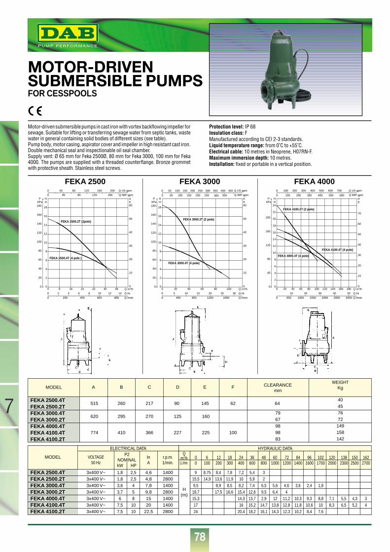
78
7
®
MOTOR-DRIVENSUBMERSIBLE PUMPSFOR CESSPOOLS
Motor-driven submersible pumps in cast iron with vortex backflowing impeller forsewage. Suitable for lifting or transferring sewage water from septic tanks, wastewater in general containing solid bodies of different sizes (see table).Pump body, motor casing, aspirator cover and impeller in high resistant cast iron.Double mechanical seal and inspectionable oil seal chamber.Supply vent: Ø 65 mm for Feka 2500Ø, 80 mm for Feka 3000, 100 mm for Feka4000. The pumps are supplied with a threaded counterflange. Bronze grommetwith protective sheath. Stainless steel screws.
Protection level: IP 68Insulation class: FManufactured according to CEI 2-3 standards.Liquid temperature range: from 0˚C to +55˚C.Electrical cable: 10 metres in Neoprene, H07RN-F.Maximum immersion depth: 10 metres.Installation: fixed or portable in a vertical position.
FEKA 2500
0
0
0
0
8 16 24 32 40 48
0
Q m3/h
Q IMP gpm
Q US gpm
Q l/s
Q l/min
0
2
4
6
8
10
12
14
16
18
0
Hm
PkPa
2 4 6 8 10 12 14
200 400 600 800
20
40
60
80
100
120
140
160
180
0
10
20
30
40
50
60
Hft
40 80 120 160 200
40 80 120 160
FEKA 2500.4T (4 pole )
FEKA 2500.2T (2pole)
FEKA 3000
0 20 40 60 80 100
0
0
Q m3/h
Q IMP gpm
Q US gpm
Q l/s
Q l/min
0
2
4
6
8
10
12
14
16
18
0
Hm
PkPa
5 10 15 20 25 30
400 800 1200 1600
20
40
60
80
100
120
140
160
180
0
10
20
30
40
50
60
Hft
FEKA 3000.4T (4 pole)
FEKA 3000.2T (2 pole)
0
0
50 100 150 200 250 300 350 400 450
50 100 150 200 250 300 350
FEKA 4000
0 20 40 60 80 100 120 140 160 180
0
0
Q m3/h
Q IMP gpm
Q US gpm
Q l/s
Q l/min
0
2
4
6
8
10
12
14
16
18
20
22
24
0
Hm
PkPa
100 200 300 400 500 600 700
10 20 30 40 50
500 1000 1500 2000 2500 3000
40
80
120
160
200
0
10
20
30
40
50
60
70
Hft
FEKA 4000.4T (4 pole)
FEKA 4100.2T (2 pole)
FEKA 4100.4T (4 pole)
0 100 200 300 400 500 600
MODEL CLEARANCEmm
WEIGHTKgA B C D E F
515 260 217 90 145 62 64
620 295 270 125 160
774 410 366 227 225 100
FEKA 2500.4TFEKA 2500.2TFEKA 3000.4TFEKA 3000.2TFEKA 4000.4TFEKA 4100.4TFEKA 4100.2T
40457672
149158142
7967989883
MODEL VOLTAGE50 Hz
P2NOMINALkW HP
FEKA 2500.4TFEKA 2500.2TFEKA 3000.4TFEKA 3000.2TFEKA 4000.4TFEKA 4100.4TFEKA 4100.2T
3x400 V~3x400 V~3x400 V~3x400 V~3x400 V~3x400 V~3x400 V~
9 8,75 8,4 7,8 7,2 5,4 315,5 14,9 13,6 11,9 10 5,9 29,5 8,9 8,5 8,2 7,4 6,5 5,6 4,6 3,6 2,4 1,818,7 17,5 16,6 15,4 12,6 9,5 6,4 415,3 14,3 13,7 2,9 12 11,2 10,3 9,3 8,8 7,1 5,5 4,3 317 16 15,2 14,7 13,8 12,8 11,8 10,6 10 8,3 6,5 5,2 424 20,4 18,2 16,1 14,3 12,3 10,2 8,4 7,6
0 6 12 18 24 36 48 60 72 84 96 102 120 138 150 1620 100 200 300 400 600 800 1000 1200 1400 1600 1700 2000 2300 2500 2700
H(m)
Qm3/hLt./min.
lnA
r.p.m.1/min.
ELECTRICAL DATA HYDRAULIC DATA
1400280014002800140014002800
4,64,87,89,81520
22,5
1,8 2,51,8 2,53,6 43,7 56 8
7,5 107,5 10
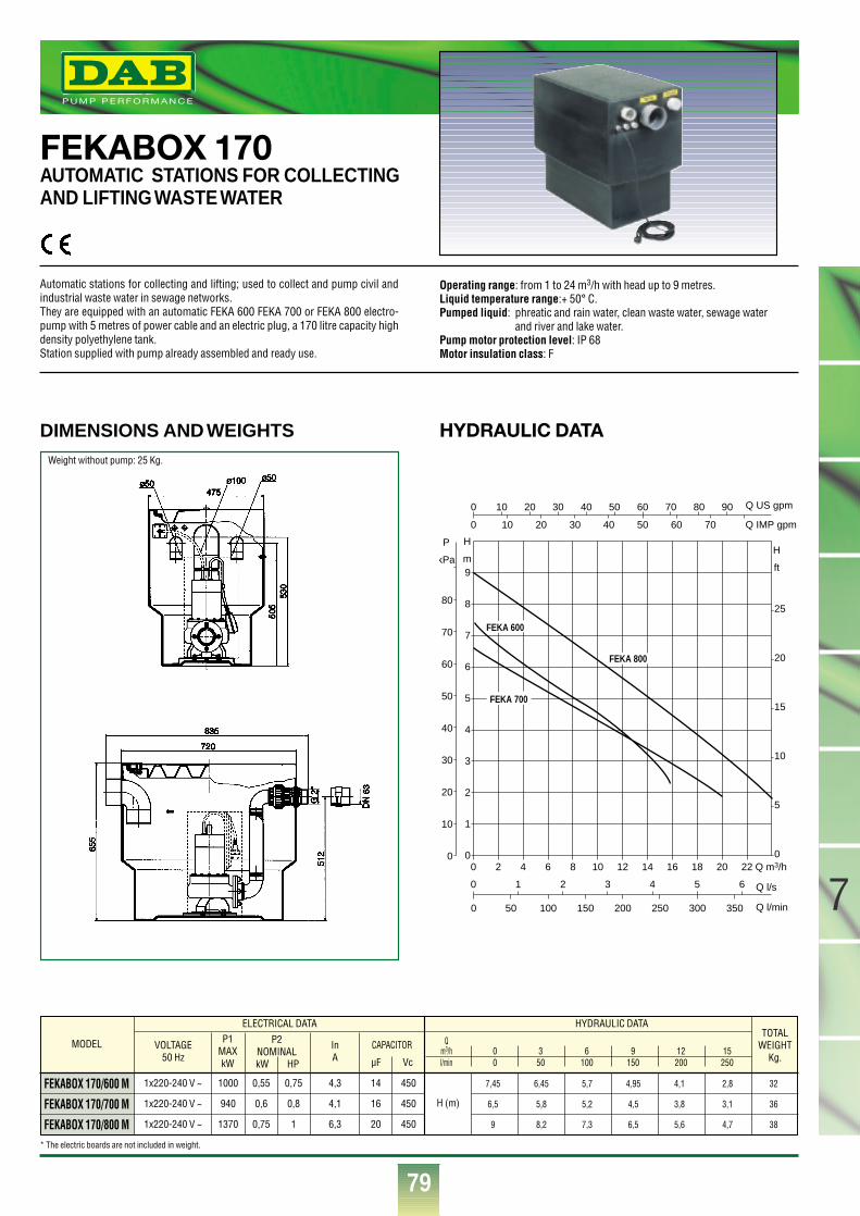
79
7
®
FEKABOX 170AUTOMATIC STATIONS FOR COLLECTINGAND LIFTING WASTE WATER
Automatic stations for collecting and lifting; used to collect and pump civil andindustrial waste water in sewage networks.They are equipped with an automatic FEKA 600 FEKA 700 or FEKA 800 electro-pump with 5 metres of power cable and an electric plug, a 170 litre capacity highdensity polyethylene tank.Station supplied with pump already assembled and ready use.
Operating range: from 1 to 24 m3/h with head up to 9 metres.Liquid temperature range:+ 50° C.Pumped liquid: phreatic and rain water, clean waste water, sewage water
and river and lake water.Pump motor protection level: IP 68Motor insulation class: F
Q m3/h0 2 4 6 8 10 12 14 16 18 20 220
1
2
3
4
5
6
7
8
9
0
5
10
15
20
25
0
0
0
Q l/s
Q l/min
Q IMP gpm
Q US gpm
0
0
1 2 3 4 5 6
50 100 150 200 250 300 350
H
mH
ft
P
kPa
10
20
30
40
50
60
70
80
10 20 30 40 50 60 70 80 90
10 20 30 40 50 60 70
FEKA 600
FEKA 800
FEKA 700
HYDRAULIC DATADIMENSIONS AND WEIGHTS
MODEL
FEKABOX 170/600 M
FEKABOX 170/700 M
FEKABOX 170/800 M
VOLTAGE50 Hz
P1MAXkW
InA
TOTALWEIGHT
Kg.
1x220-240 V ~
1x220-240 V ~
1x220-240 V ~
1000
940
1370
0,55
0,6
0,75
0,75
0,8
1
14
16
20
450
450
450
H (m)
4,3
4,1
6,3
ELECTRICAL DATA HYDRAULIC DATA
P2NOMINALkW HP
CAPACITOR
µF Vc
Qm3/h 0 3 6 9 12 15l/min 0 50 100 150 200 250
7,45 6,45 5,7 4,95 4,1 2,8 32
6,5 5,8 5,2 4,5 3,8 3,1 36
9 8,2 7,3 6,5 5,6 4,7 38
Weight without pump: 25 Kg.
* The electric boards are not included in weight.
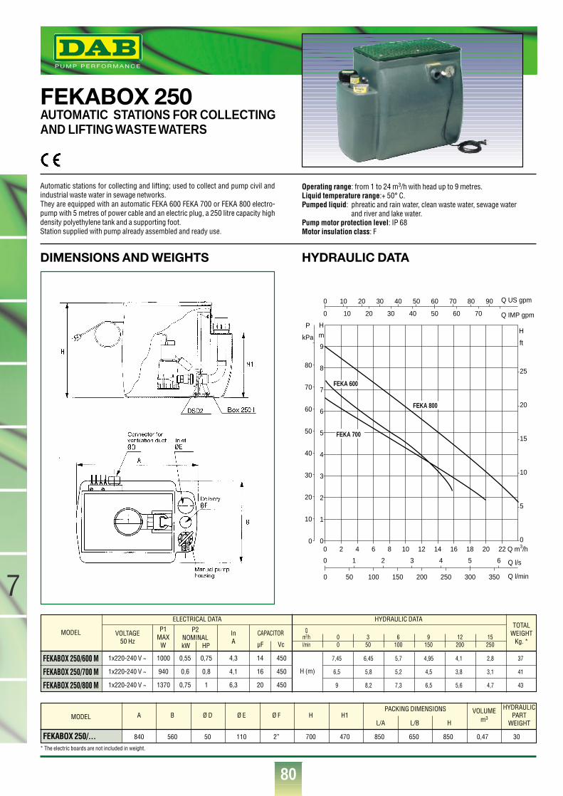
80
7
®
Q m3/h0 2 4 6 8 10 12 14 16 18 20 220
1
2
3
4
5
6
7
8
9
0
5
10
15
20
25
0
0
0
Q l/s
Q l/min
Q IMP gpm
Q US gpm
0
0
1 2 3 4 5 6
50 100 150 200 250 300 350
Hm
H
ft
P
kPa
10
20
30
40
50
60
70
80
10 20 30 40 50 60 70 80 90
10 20 30 40 50 60 70
FEKA 600
FEKA 800
FEKA 700
HYDRAULIC DATADIMENSIONS AND WEIGHTS
FEKABOX 250 AUTOMATIC STATIONS FOR COLLECTINGAND LIFTING WASTE WATERS
Automatic stations for collecting and lifting; used to collect and pump civil andindustrial waste water in sewage networks.They are equipped with an automatic FEKA 600 FEKA 700 or FEKA 800 electro-pump with 5 metres of power cable and an electric plug, a 250 litre capacity highdensity polyethylene tank and a supporting foot.Station supplied with pump already assembled and ready use.
Operating range: from 1 to 24 m3/h with head up to 9 metres.Liquid temperature range:+ 50° C.Pumped liquid: phreatic and rain water, clean waste water, sewage water
and river and lake water.Pump motor protection level: IP 68Motor insulation class: F
FEKABOX 250/... 840 560 50 110 2” 700 470 850 650 850 0,47 30
A B Ø D Ø E Ø F H H1PACKING DIMENSIONS HYDRAULIC
PARTWEIGHT
VOLUMEm3
L/A L/B HMODEL
* The electric boards are not included in weight.
MODEL
FEKABOX 250/600 M
FEKABOX 250/700 M
FEKABOX 250/800 M
VOLTAGE50 Hz
P1MAX
W
InA
TOTALWEIGHT
Kg. *
1x220-240 V ~
1x220-240 V ~
1x220-240 V ~
1000
940
1370
0,55
0,6
0,75
0,75
0,8
1
14
16
20
450
450
450
H (m)
4,3
4,1
6,3
ELECTRICAL DATA HYDRAULIC DATA
P2NOMINALkW HP
CAPACITOR
µF Vc
Qm3/h 0 3 6 9 12 15l/min 0 50 100 150 200 250
7,45 6,45 5,7 4,95 4,1 2,8 37
6,5 5,8 5,2 4,5 3,8 3,1 41
9 8,2 7,3 6,5 5,6 4,7 43
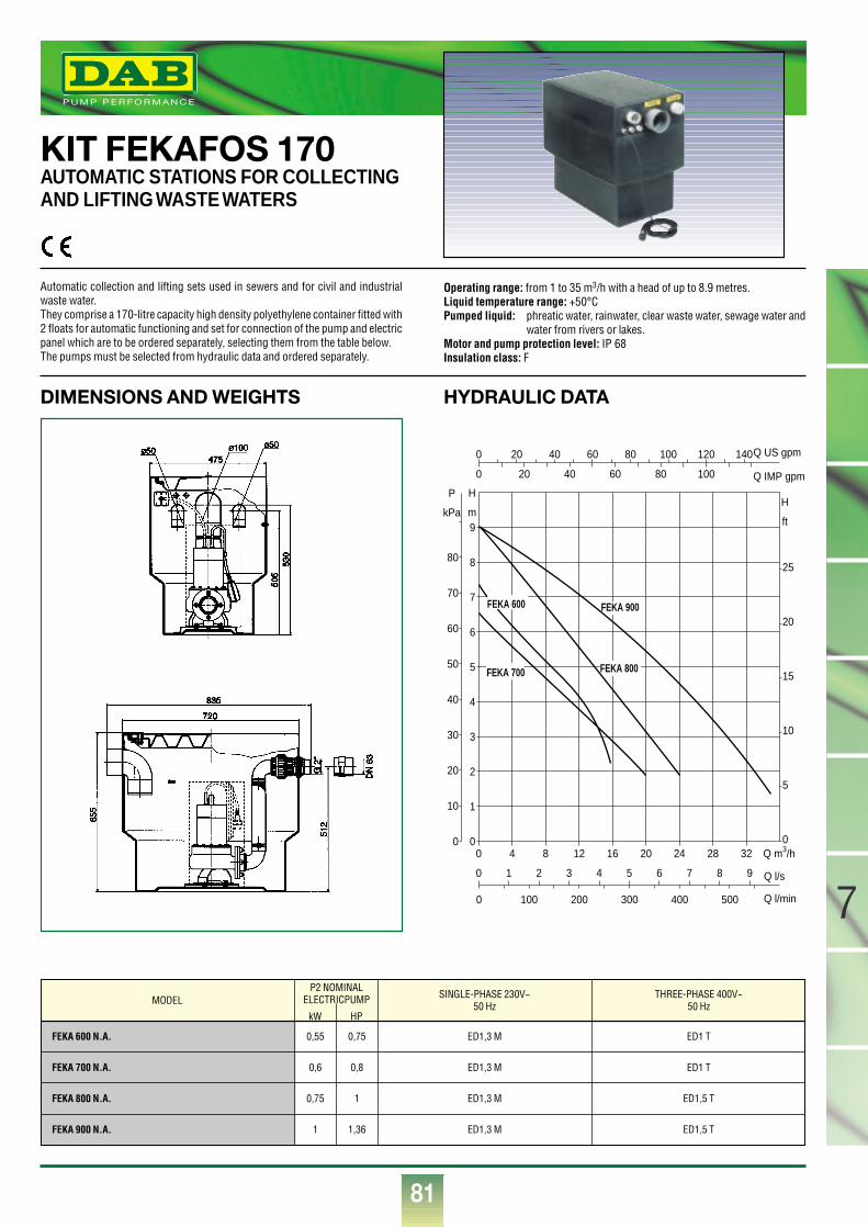
81
7
®
Q m3/h0 4 8 12 16 20 24 28 320
1
2
3
4
5
6
7
8
9
0
5
10
15
20
25
0
0
0
Q l/s
Q l/min
Q IMP gpm
Q US gpm
0
0
1 2 3 4 5 6 7 8 9
100 200 300 400 500
H
mH
ft
P
kPa
10
20
30
40
50
60
70
80
20 40 60 80 100 120 140
20 40 60 80 100
FEKA 800
FEKA 900
FEKA 700
FEKA 600
HYDRAULIC DATADIMENSIONS AND WEIGHTS
KIT FEKAFOS 170AUTOMATIC STATIONS FOR COLLECTINGAND LIFTING WASTE WATERS
Automatic collection and lifting sets used in sewers and for civil and industrialwaste water.They comprise a 170-litre capacity high density polyethylene container fitted with2 floats for automatic functioning and set for connection of the pump and electricpanel which are to be ordered separately, selecting them from the table below.The pumps must be selected from hydraulic data and ordered separately.
Operating range: from 1 to 35 m3/h with a head of up to 8.9 metres.Liquid temperature range: +50°CPumped liquid: phreatic water, rainwater, clear waste water, sewage water and
water from rivers or lakes.Motor and pump protection level: IP 68Insulation class: F
MODEL SINGLE-PHASE 230V~50 Hz
P2 NOMINALELECTRICPUMP
kW HP
THREE-PHASE 400V~50 Hz
ED1 T
ED1 T
ED1,5 T
ED1,5 T
ED1,3 M
ED1,3 M
ED1,3 M
ED1,3 M
0,55 0,75
0,6 0,8
0,75 1
1 1,36
FEKA 600 N.A.
FEKA 700 N.A.
FEKA 800 N.A.
FEKA 900 N.A.
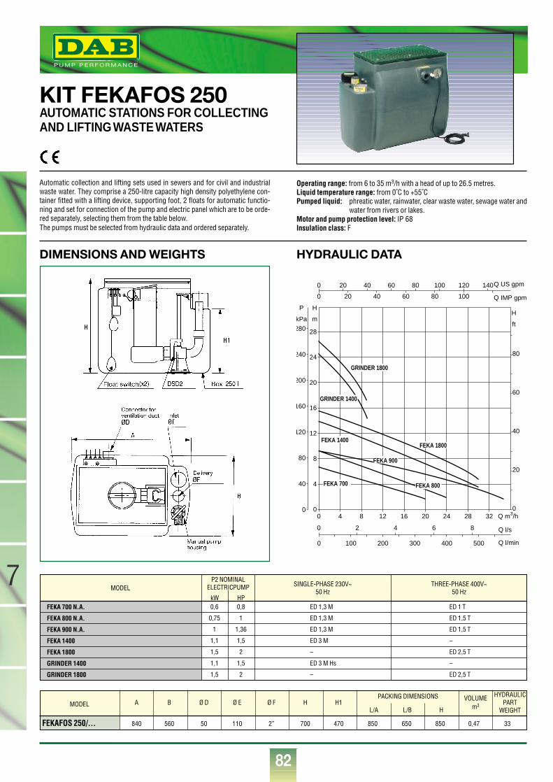
82
7
®
Q m3/h0 4 8 12 16 20 24 28 320
4
8
12
16
20
24
28
0
20
40
60
80
0
0
0
Q l/s
Q l/min
Q IMP gpm
Q US gpm
0
0
2 4 6 8
100 200 300 400 500
H
mH
ft
P
kPa
40
80
120
160
200
240
280
20 40 60 80 100 120 140
20 40 60 80 100
FEKA 800
FEKA 900
FEKA 700
FEKA 1400FEKA 1800
GRINDER 1400
GRINDER 1800
HYDRAULIC DATADIMENSIONS AND WEIGHTS
KIT FEKAFOS 250AUTOMATIC STATIONS FOR COLLECTINGAND LIFTING WASTE WATERS
Automatic collection and lifting sets used in sewers and for civil and industrialwaste water. They comprise a 250-litre capacity high density polyethylene con-tainer fitted with a lifting device, supporting foot, 2 floats for automatic functio-ning and set for connection of the pump and electric panel which are to be orde-red separately, selecting them from the table below.The pumps must be selected from hydraulic data and ordered separately.
Operating range: from 6 to 35 m3/h with a head of up to 26.5 metres.Liquid temperature range: from 0˚C to +55˚CPumped liquid: phreatic water, rainwater, clear waste water, sewage water and
water from rivers or lakes.Motor and pump protection level: IP 68Insulation class: F
FEKAFOS 250/… 840 560 50 110 2” 700 470 850 650 850 0,47 33
A B Ø D Ø E Ø F H H1PACKING DIMENSIONS HYDRAULIC
PARTWEIGHT
VOLUMEm3
L/A L/B HMODEL
MODEL SINGLE-PHASE 230V~50 Hz
THREE-PHASE 400V~50 Hz
ED 1 T
ED 1,5 T
ED 1,5 T
–
ED 2,5 T
–
ED 2,5 T
ED 1,3 M
ED 1,3 M
ED 1,3 M
ED 3 M
–
ED 3 M Hs
–
FEKA 700 N.A.
FEKA 800 N.A.
FEKA 900 N.A.
FEKA 1400
FEKA 1800
GRINDER 1400
GRINDER 1800
P2 NOMINALELECTRICPUMP
kW HP0,6 0,8
0,75 1
1 1,36
1,1 1,5
1,5 2
1,1 1,5
1,5 2
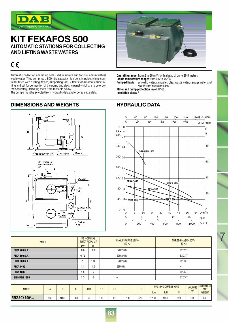
83
7
®
KIT FEKAFOS 500AUTOMATIC STATIONS FOR COLLECTINGAND LIFTING WASTE WATERS
Q m3/h0 8 16 24 32 40 48 56 640
4
8
12
16
20
24
28
0
20
40
60
80
0
0
0
Q l/s
Q l/min
Q IMP gpm
Q US gpm
0
0
4 8 12 16
200 400 600 800 1000
H
mH
ft
P
kPa
40
80
120
160
200
240
280
40 80 120 160 200 240 280
40 80 120 160 200
FEKA 800
FEKA 900
FEKA 700
FEKA 1400FEKA 1800
GRINDER 1800
HYDRAULIC DATADIMENSIONS AND WEIGHTS
Automatic collection and lifting sets used in sewers and for civil and industrialwaste water. They comprise a 500-litre capacity high density polyethylene con-tainer fitted with a lifting device, supporting foot, 2 floats for automatic functio-ning and set for connection of the pump and electric panel which are to be orde-red separately, selecting them from the table below.The pumps must be selected from hydraulic data and ordered separately.
Operating range: from 2 to 68 m3/h with a head of up to 26.5 metres.Liquid temperature range: from 0˚C to +55˚CPumped liquid: phreatic water, rainwater, clear waste water, sewage water and
water from rivers or lakes.Motor and pump protection level: IP 68Insulation class: F
MODEL SINGLE-PHASE 230V~50 Hz
THREE-PHASE 400V~50 Hz
E2D2 T
E2D3 T
E2D3 T
–
E2D5 T
E2D5 T
E2D 2,6 M
E2D 2,6 M
E2D 2,6 M
E2D 6 M
–
–
FEKA 700 N.A.
FEKA 800 N.A.
FEKA 900 N.A.
FEKA 1400
FEKA 1800
GRINDER 1800
FEKABOX 500/… 880 1060 880 50 110 2” 700 470 1200 1000 850 1,0 59
A B C Ø D Ø E Ø F H H1PACKING DIMENSIONS HYDRAULIC
PARTWEIGHT
VOLUMEm3
L/A L/B HMODEL
P2 NOMINALELECTRICPUMP
kW HP0,6 0,8
0,75 1
1 1,36
1,1 1,5
1,5 2
1,5 2
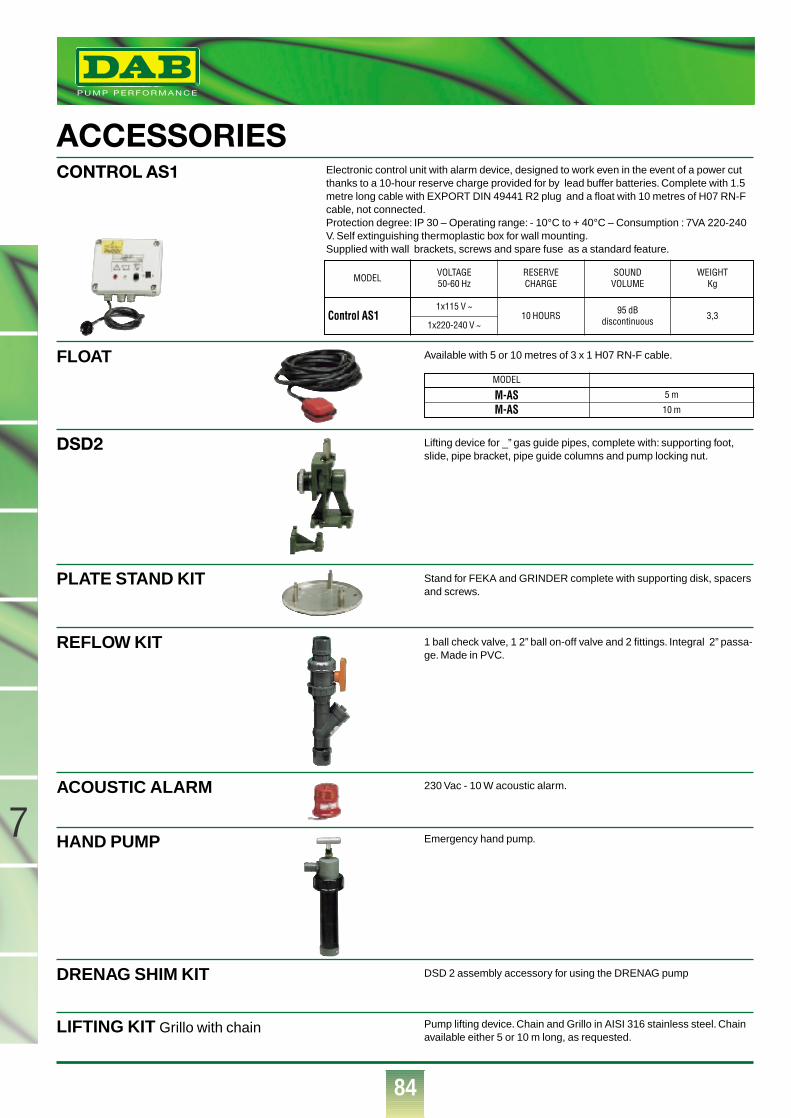
84
7
®
ACCESSORIESCONTROL AS1
FLOAT
DSD2
PLATE STAND KIT
REFLOW KIT
ACOUSTIC ALARM
HAND PUMP
DRENAG SHIM KIT
LIFTING KIT Grillo with chain Pump lifting device. Chain and Grillo in AISI 316 stainless steel. Chainavailable either 5 or 10 m long, as requested.
DSD 2 assembly accessory for using the DRENAG pump
Emergency hand pump.
230 Vac - 10 W acoustic alarm.
1 ball check valve, 1 2” ball on-off valve and 2 fittings. Integral 2” passa-ge. Made in PVC.
Stand for FEKA and GRINDER complete with supporting disk, spacersand screws.
Lifting device for _” gas guide pipes, complete with: supporting foot,slide, pipe bracket, pipe guide columns and pump locking nut.
MODEL
M-ASM-AS 5 m
10 m
Available with 5 or 10 metres of 3 x 1 H07 RN-F cable.
Electronic control unit with alarm device, designed to work even in the event of a power cutthanks to a 10-hour reserve charge provided for by lead buffer batteries. Complete with 1.5metre long cable with EXPORT DIN 49441 R2 plug and a float with 10 metres of H07 RN-Fcable, not connected.Protection degree: IP 30 – Operating range: - 10°C to + 40°C – Consumption : 7VA 220-240V. Self extinguishing thermoplastic box for wall mounting.Supplied with wall brackets, screws and spare fuse as a standard feature.
VOLTAGE50-60 Hz
1x115 V ~
1x220-240 V ~
RESERVECHARGE
10 HOURS
SOUNDVOLUME
95 dBdiscontinuous
WEIGHTKg
3,3
MODEL
Control AS1
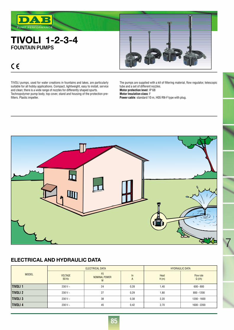
85
®
TIVOLI 1-2-3-4FOUNTAIN PUMPS
TIVOLI pumps, used for water creations in fountains and lakes, are particularlysuitable for all hobby applications. Compact, lightweight, easy to install, serviceand clean; there is a wide range of nozzles for differently shaped spurts.Technopolymer pump body, top cover, stand and housing of the protection pre-filters. Plastic impeller.
The pumps are supplied with a kit of filtering material, flow regulator, telescopictube and a set of different nozzles.Motor protection level: IP 68Motor Insulation class: FPower cable: standard 10 m, H05 RN-F type with plug.
ELECTRICAL AND HYDRAULIC DATA
VOLTAGE50 Hz
230 V ~
230 V ~
230 V ~
230 V ~
P2NOMINAL POWER
W
24
27
38
45
InA
0,28
0,29
0,38
0,42
MODEL
TIVOLI 1
TIVOLI 2
TIVOLI 3
TIVOLI 4
ELECTRICAL DATA HYDRAULIC DATA
HeadH (m)
1,40
1,80
2,20
2,70
Flow rateQ (l/h)
600 - 800
800 - 1200
1200 - 1600
1600 - 2200
7
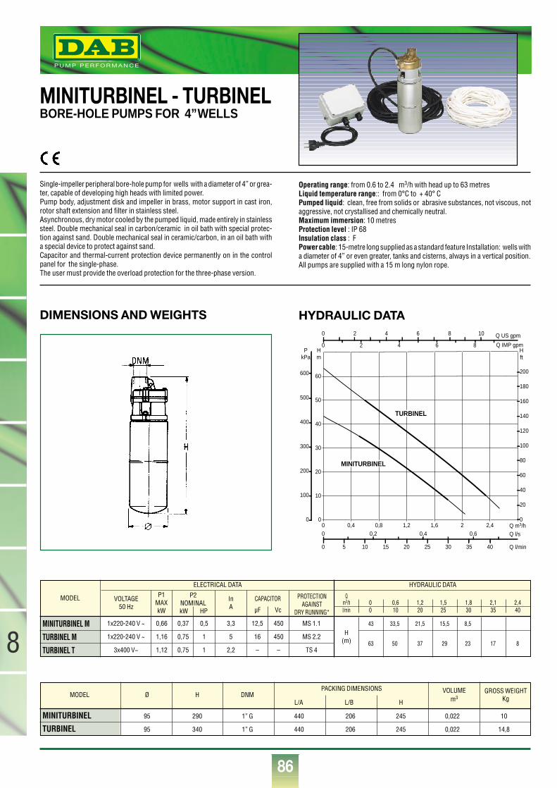
86
®
0 0,4 0,8 1,2 1,6 2 2,4 Q m3/h0
10
20
30
40
50
60
Hm
0
100
200
300
400
500
600
PkPa
0 5 10 15 20 25 30 35 40 Q l/min
0 0,2 0,4 0,6 Q l/s
0
20
40
60
80
100
120
140
160
180
200
H ft
0 2 4 6 8 10 Q US gpm
0 2 4 6 8 Q IMP gpm
MINITURBINEL
TURBINEL
HYDRAULIC DATADIMENSIONS AND WEIGHTS
MINITURBINEL - TURBINELBORE-HOLE PUMPS FOR 4”WELLS
Single-impeller peripheral bore-hole pump for wells with a diameter of 4” or grea-ter, capable of developing high heads with limited power.Pump body, adjustment disk and impeller in brass, motor support in cast iron,rotor shaft extension and filter in stainless steel.Asynchronous, dry motor cooled by the pumped liquid, made entirely in stainlesssteel. Double mechanical seal in carbon/ceramic in oil bath with special protec-tion against sand. Double mechanical seal in ceramic/carbon, in an oil bath witha special device to protect against sand.Capacitor and thermal-current protection device permanently on in the controlpanel for the single-phase.The user must provide the overload protection for the three-phase version.
Operating range: from 0.6 to 2.4 m3/h with head up to 63 metresLiquid temperature range:: from 0°C to + 40° C Pumped liquid: clean, free from solids or abrasive substances, not viscous, notaggressive, not crystallised and chemically neutral.Maximum immersion: 10 metresProtection level : IP 68Insulation class : FPower cable: 15-metre long supplied as a standard feature Installation: wells witha diameter of 4” or even greater, tanks and cisterns, always in a vertical position.All pumps are supplied with a 15 m long nylon rope.
MODEL
MINITURBINEL M
TURBINEL M
TURBINEL T
VOLTAGE50 Hz
P1MAXkW
InA
1x220-240 V ~
1x220-240 V ~
3x400 V~
0,66
1,16
1,12
0,37
0,75
0,75
0,5
1
1
12,5
16
–
450
450
–
MS 1.1
MS 2.2
TS 4
H (m)
3,3
5
2,2
ELECTRICAL DATA HYDRAULIC DATA
P2NOMINALkW HP
CAPACITOR
µF Vc
PROTECTIONAGAINST
DRY RUNNING*
Qm3/h 0 0,6 1,2 1,5 1,8 2,1 2,4l/min 0 10 20 25 30 35 40
43 33,5 21,5 15,5 8,5
63 50 37 29 23 17 8
MINITURBINEL 95 290 1” G 440 206 245 0,022 10
TURBINEL 95 340 1” G 440 206 245 0,022 14,8
MODEL Ø H DNMPACKING DIMENSIONS GROSS WEIGHT
KgVOLUME
m3L/A L/B H
8
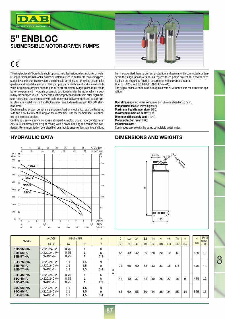
87
8
®
5” ENBLOCSUBMERSIBLE MOTOR-DRIVEN PUMPS
HYDRAULIC DATA DIMENSIONS AND WEIGHTS
The single-piece 5” bore-hole electric pump, installed inside collecting tanks or wells,6” septic tanks, Roman wells, basins or watercourses, is suitable for providing pres-surised water in domestic systems, small-scale farming and sprinkling systems forgardens and vegetable gardens. The pump is particularly silent and is used insidewells or tanks to prevent suction and turn off problems. Single-piece multi-stagebore-hole pump with hydraulic assembly positioned under the motor which is coo-led by the pumped liquid. The thermoplastic impellers and diffusers offer high abra-sion resistance. Upper support with technopolymer delivery mouth and suction gril-le. Stainless steel drive shaft and bolts and screws. External casing in AISI 304 stain-less steel.Double sealing system comprising a ceramic/carbon mechanical seal on the pumpside and a double retention ring on the motor side. The mechanical seal is lubrica-ted by the motor coolant.Continuous service asynchronous submersible motor. Stator incorporated in anAISI 304 stainless steel airtight casing with a cover housing the cables and con-denser. Rotor mounted on oversized ball bearings to ensure silent running and long
life. Incorporated thermal current protection and permanently connected conden-ser in the single-phase version. As regards three-phase protection, a motor over-load cut out should be fitted, in accordance with current standards.Built to IEC 2-3 and IEC 61-69 (EN 60335-2-41).The single-phase versions can be supplied with or without floats for automatic ope-ration.
Operating range: up to a maximum of 9 m3/h with a head up to 77 m.Pumped liquid: clean water in general.Maximum liquid temperature: 30˚C.Maximum immersion depth: 20 m.Diameter of the supply vent: 1 1/4”.Motor protection level: IP68.Insulation class: F.Continuous service with the pump completely under water.
VOLTAGE P2 NOMINAL In
50 Hz kW HP A
S5B-5M-NAS5B-5M-AS5B-5T-NA
1x220/240 V~1x220/240 V~
3x400 V~
0,750,750,75
111
66
2,3
99
3,4 Hm6
62,3
99
3,4
111
1,51,51,5
1,51,51,5
0,750,750,75
1,11,11,1
1,11,11,1
1x220/240 V~1x220/240 V~
3x400 V~
1x220/240 V~1x220/240 V~
3x400 V~
1x220/240 V~1x220/240 V~
3x400 V~
S5B-7M-NAS5B-7M-AS5B-7T-NA
S5C-4M-NAS5C-4M-AS5C-4T-NA
S5C-6M-NAS5C-6M-AS5C-6T-NA
56 49 42 36 28 20 10 5 480 12
570 16
475 12
575 16
0 20 40 60 80 100 110 130 150
0 1,2 2,4 3,6 4,8 6 6,6 7,8 9
77 68 60 52 43 31 15 6,5
43 40 37 34 30 25 22 16 9
66 60 55 50 44 38 34 25 14
H
mm
GROSSWEIGHT
Kg
0 1 2 3 4 5 6 7 8 9
0
0
0
0
Q m3/h
Q IMP gpmQ US gpm
Q l/sQ l/min
0
10
20
30
40
50
60
70
80
0
Hm
PkPa
0,5 1 1,5
20 40 60 80 100 120 140
100
200
300
400
500
600
700
800
0
50
100
150
200
250
Hft
5 10 15 20 25 30 35
5 10 15 20 25 30
S5B-5
S5B-7
S5C-4
S5C-6
1 1/4"G
140
H
MODEL
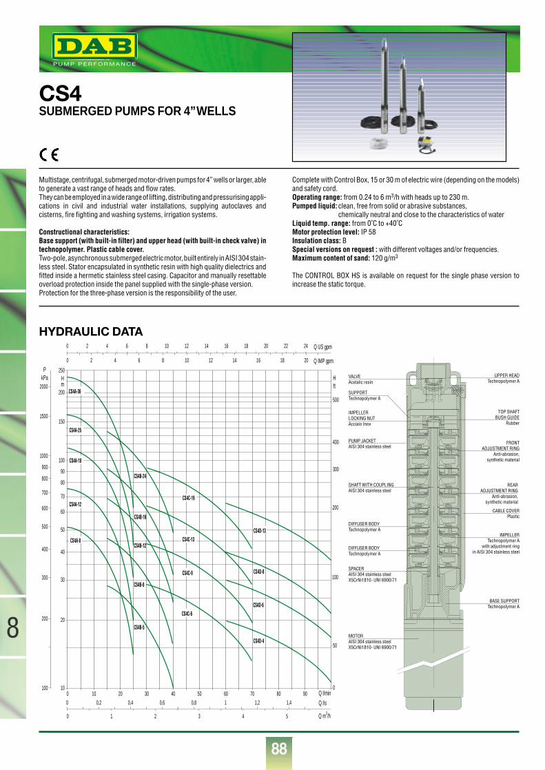
88
8
®
CS4SUBMERGED PUMPS FOR 4”WELLS
Multistage, centrifugal, submerged motor-driven pumps for 4” wells or larger, ableto generate a vast range of heads and flow rates.They can be employed in a wide range of lifting, distributing and pressurising appli-cations in civil and industrial water installations, supplying autoclaves andcisterns, fire fighting and washing systems, irrigation systems.
Constructional characteristics:Base support (with built-in filter) and upper head (with built-in check valve) intechnopolymer. Plastic cable cover.Two-pole, asynchronous submerged electric motor, built entirely in AISI 304 stain-less steel. Stator encapsulated in synthetic resin with high quality dielectrics andfitted inside a hermetic stainless steel casing. Capacitor and manually resettableoverload protection inside the panel supplied with the single-phase version. Protection for the three-phase version is the responsibility of the user.
Complete with Control Box, 15 or 30 m of electric wire (depending on the models)and safety cord.Operating range: from 0.24 to 6 m3/h with heads up to 230 m.Pumped liquid: clean, free from solid or abrasive substances,
chemically neutral and close to the characteristics of waterLiquid temp. range: from 0˚C to +40˚CMotor protection level: IP 58Insulation class: BSpecial versions on request : with different voltages and/or frequencies.Maximum content of sand: 120 g/m3
The CONTROL BOX HS is available on request for the single phase version toincrease the static torque.
HYDRAULIC DATA
10
200
250
150
100
90
80
70
60
50
40
30
20
Hm
Hft
PkPa
100
1500
2000
1000
900
800
700
600
500
400
300
200
50
100
200
300
400
500
0 10 20 30 40 50 60 70 80 90
Q m3/h
Q l/s
Q l/min0 0,2 0,4 0,6 0,8 1 1,2 1,4
0 1 2 3 4 5
Q IMP gpm
Q US gpm
0
0
2 4 6 8 10 12 14 16 18 20
2 4 6 8 10 12 14 16 18 20 22 24
CS4A-12
CS4A-18
CS4A-25
CS4A-36
CS4B-5
CS4B-8
CS4B-12
CS4B-16
CS4B-24
CS4C-6
CS4C-9
CS4C-13
CS4C-19
CS4D-4
CS4D-6
CS4D-8
CS4D-13
0
CS4A-8
BASE SUPPORTTechnopolymer A
IMPELLER Technopolymer A
with adjustment ringin AISI 304 stainless steel
DIFFUSER BODYTechnopolymer A
DIFFUSER BODYTechnopolymer A
IMPELLER LOCKING NUTAcciaio Inox
VALVEAcetalic resin
UPPER HEADTechnopolymer A
CABLE COVERPlastic
FRONTADJUSTMENT RING
Anti-abrasion,synthetic material
TOP SHAFTBUSH GUIDE
Rubber
REARADJUSTMENT RING
Anti-abrasion,synthetic material
SHAFT WITH COUPLINGAISI 304 stainless steel
MOTORAISI 304 stainless steelX5CrNi1810- UNI 6900/71
PUMP JACKETAISI 304 stainless steel
SPACERAISI 304 stainless steelX5CrNi1810- UNI 6900/71
SUPPORTTechnopolymer A
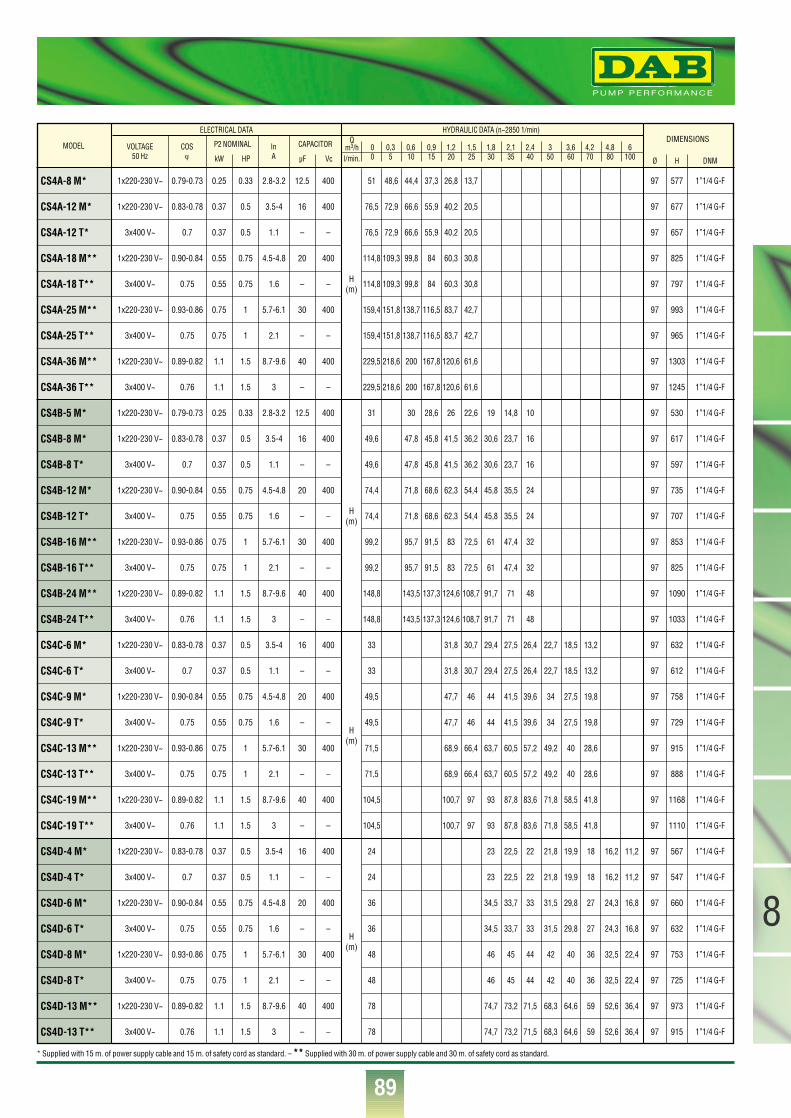
89
8
®
CS4A-8 M*
CS4A-12 M*
CS4A-12 T*
CS4A-18 M**
CS4A-18 T**
CS4A-25 M**
CS4A-25 T**
CS4A-36 M**
CS4A-36 T**
CS4B-5 M*
CS4B-8 M*
CS4B-8 T*
CS4B-12 M*
CS4B-12 T*
CS4B-16 M**
CS4B-16 T**
CS4B-24 M**
CS4B-24 T**
CS4C-6 M*
CS4C-6 T*
CS4C-9 M*
CS4C-9 T*
CS4C-13 M**
CS4C-13 T**
CS4C-19 M**
CS4C-19 T**
CS4D-4 M*
CS4D-4 T*
CS4D-6 M*
CS4D-6 T*
CS4D-8 M*
CS4D-8 T*
CS4D-13 M**
CS4D-13 T**
MODEL VOLTAGE50 Hz
COSϕ
InA
P2 NOMINAL
kW HP
CAPACITOR
µF Vc
ELECTRICAL DATA HYDRAULIC DATA (n~2850 1/min)DIMENSIONS
Ø H DNM
1x220-230 V~
1x220-230 V~
3x400 V~
1x220-230 V~
3x400 V~
1x220-230 V~
3x400 V~
1x220-230 V~
3x400 V~
1x220-230 V~
1x220-230 V~
3x400 V~
1x220-230 V~
3x400 V~
1x220-230 V~
3x400 V~
1x220-230 V~
3x400 V~
1x220-230 V~
3x400 V~
1x220-230 V~
3x400 V~
1x220-230 V~
3x400 V~
1x220-230 V~
3x400 V~
1x220-230 V~
3x400 V~
1x220-230 V~
3x400 V~
1x220-230 V~
3x400 V~
1x220-230 V~
3x400 V~
0.79-0.73
0.83-0.78
0.7
0.90-0.84
0.75
0.93-0.86
0.75
0.89-0.82
0.76
0.79-0.73
0.83-0.78
0.7
0.90-0.84
0.75
0.93-0.86
0.75
0.89-0.82
0.76
0.83-0.78
0.7
0.90-0.84
0.75
0.93-0.86
0.75
0.89-0.82
0.76
0.83-0.78
0.7
0.90-0.84
0.75
0.93-0.86
0.75
0.89-0.82
0.76
0.25
0.37
0.37
0.55
0.55
0.75
0.75
1.1
1.1
0.25
0.37
0.37
0.55
0.55
0.75
0.75
1.1
1.1
0.37
0.37
0.55
0.55
0.75
0.75
1.1
1.1
0.37
0.37
0.55
0.55
0.75
0.75
1.1
1.1
0.33
0.5
0.5
0.75
0.75
1
1
1.5
1.5
0.33
0.5
0.5
0.75
0.75
1
1
1.5
1.5
0.5
0.5
0.75
0.75
1
1
1.5
1.5
0.5
0.5
0.75
0.75
1
1
1.5
1.5
2.8-3.2
3.5-4
1.1
4.5-4.8
1.6
5.7-6.1
2.1
8.7-9.6
3
2.8-3.2
3.5-4
1.1
4.5-4.8
1.6
5.7-6.1
2.1
8.7-9.6
3
3.5-4
1.1
4.5-4.8
1.6
5.7-6.1
2.1
8.7-9.6
3
3.5-4
1.1
4.5-4.8
1.6
5.7-6.1
2.1
8.7-9.6
3
12.5
16
–
20
–
30
–
40
–
12.5
16
–
20
–
30
–
40
–
16
–
20
–
30
–
40
–
16
–
20
–
30
–
40
–
400
400
–
400
–
400
–
400
–
400
400
–
400
–
400
–
400
–
400
–
400
–
400
–
400
–
400
–
400
–
400
–
400
–
51 48,6 44,4 37,3 26,8 13,7
76,5 72,9 66,6 55,9 40,2 20,5
76,5 72,9 66,6 55,9 40,2 20,5
114,8 109,3 99,8 84 60,3 30,8
114,8 109,3 99,8 84 60,3 30,8
159,4 151,8 138,7 116,5 83,7 42,7
159,4 151,8 138,7 116,5 83,7 42,7
229,5 218,6 200 167,8 120,6 61,6
229,5 218,6 200 167,8 120,6 61,6
31 30 28,6 26 22,6 19 14,8 10
49,6 47,8 45,8 41,5 36,2 30,6 23,7 16
49,6 47,8 45,8 41,5 36,2 30,6 23,7 16
74,4 71,8 68,6 62,3 54,4 45,8 35,5 24
74,4 71,8 68,6 62,3 54,4 45,8 35,5 24
99,2 95,7 91,5 83 72,5 61 47,4 32
99,2 95,7 91,5 83 72,5 61 47,4 32
148,8 143,5 137,3 124,6 108,7 91,7 71 48
148,8 143,5 137,3 124,6 108,7 91,7 71 48
33 31,8 30,7 29,4 27,5 26,4 22,7 18,5 13,2
33 31,8 30,7 29,4 27,5 26,4 22,7 18,5 13,2
49,5 47,7 46 44 41,5 39,6 34 27,5 19,8
49,5 47,7 46 44 41,5 39,6 34 27,5 19,8
71,5 68,9 66,4 63,7 60,5 57,2 49,2 40 28,6
71,5 68,9 66,4 63,7 60,5 57,2 49,2 40 28,6
104,5 100,7 97 93 87,8 83,6 71,8 58,5 41,8
104,5 100,7 97 93 87,8 83,6 71,8 58,5 41,8
24 23 22,5 22 21,8 19,9 18 16,2 11,2
24 23 22,5 22 21,8 19,9 18 16,2 11,2
36 34,5 33,7 33 31,5 29,8 27 24,3 16,8
36 34,5 33,7 33 31,5 29,8 27 24,3 16,8
48 46 45 44 42 40 36 32,5 22,4
48 46 45 44 42 40 36 32,5 22,4
78 74,7 73,2 71,5 68,3 64,6 59 52,6 36,4
78 74,7 73,2 71,5 68,3 64,6 59 52,6 36,4
H(m)
H(m)
H(m)
H(m)
Qm3/hl/min.
0 0,3 0,6 0,9 1,2 1,5 1,8 2,1 2,4 3 3,6 4,2 4,8 60 5 10 15 20 25 30 35 40 50 60 70 80 100
97
97
97
97
97
97
97
97
97
97
97
97
97
97
97
97
97
97
97
97
97
97
97
97
97
97
97
97
97
97
97
97
97
97
577
677
657
825
797
993
965
1303
1245
530
617
597
735
707
853
825
1090
1033
632
612
758
729
915
888
1168
1110
567
547
660
632
753
725
973
915
1”1/4 G-F
1”1/4 G-F
1”1/4 G-F
1”1/4 G-F
1”1/4 G-F
1”1/4 G-F
1”1/4 G-F
1”1/4 G-F
1”1/4 G-F
1”1/4 G-F
1”1/4 G-F
1”1/4 G-F
1”1/4 G-F
1”1/4 G-F
1”1/4 G-F
1”1/4 G-F
1”1/4 G-F
1”1/4 G-F
1”1/4 G-F
1”1/4 G-F
1”1/4 G-F
1”1/4 G-F
1”1/4 G-F
1”1/4 G-F
1”1/4 G-F
1”1/4 G-F
1”1/4 G-F
1”1/4 G-F
1”1/4 G-F
1”1/4 G-F
1”1/4 G-F
1”1/4 G-F
1”1/4 G-F
1”1/4 G-F
* Supplied with 15 m. of power supply cable and 15 m. of safety cord as standard. – ** Supplied with 30 m. of power supply cable and 30 m. of safety cord as standard.
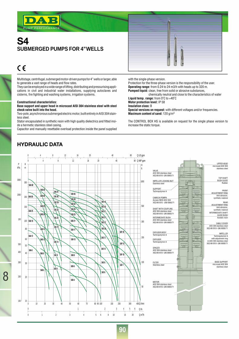
90
8
®
HYDRAULIC DATA
S4SUBMERGED PUMPS FOR 4”WELLS
Multistage, centrifugal, submerged motor-driven pumps for 4” wells or larger, ableto generate a vast range of heads and flow rates.They can be employed in a wide range of lifting, distributing and pressurising appli-cations in civil and industrial water installations, supplying autoclaves andcisterns, fire fighting and washing systems, irrigation systems.
Constructional characteristics:Base support and upper head in microcast AISI 304 stainless steel with steelcheck valve built into the head.Two-pole, asynchronous submerged electric motor, built entirely in AISI 304 stain-less steel.Stator encapsulated in synthetic resin with high quality dielectrics and fitted insi-de a hermetic stainless steel casing.Capacitor and manually resettable overload protection inside the panel supplied
with the single-phase version. Protection for the three-phase version is the responsibility of the user.Operating range: from 0.24 to 24 m3/h with heads up to 320 m.Pumped liquid: clean, free from solid or abrasive substances,
chemically neutral and close to the characteristics of waterLiquid temp. range: from 0˚C to +40˚CMotor protection level: IP 58Insulation class: BSpecial versions on request: with different voltages and/or frequencies.Maximum content of sand: 120 g/m3
The CONTROL BOX HS is available on request for the single phase version toincrease the static torque.
10
20
30
40
50
60
80
100
150
200
300
Hm
Hft
PkPa
100
200
300
400
500
100
2000
3000
50
100
200
300
500
1000
0 10 20 30 40 50 60 70 80 40030020015010090
Q m3/h
Q l/s
Q l/min
0 1 2 3 4 5 6
0 4 8 12 16 20 40 80
S4A-8
S4A-12
S4A-18
S4A-25
S4A-36
S4A-50
S4B-5
S4B-8
S4B-12
S4B-16
S4B-24
S4B-32
S4B-40
S4B-48
S4C-6
S4C-9
S4C-13
S4C-19
S4C-25
S4C-32
S4C-39
S4C-45
S4C-51
S4D-4
S4D-6
S4D-17
S4D-21
S4D-13
S4E-6
S4E-8
S4E-12
S4E-17
S4E-20
S4E-23
S4E-27
S4E-31
S4E-36
S4E-42
S4F-7
S4F-10
S4F-13
S4F-18
S4D-25
S4D-29
S4D-34
S4D-38
S4D-45
S4D-8
Q IMP gpm
Q US gpm
0 1 2 3 4 5 6
0 4 8 12 16 20 40 80
8 10 15 20
CABLE COVERAISI 304 stainless steel
X5CrNi1810- UNI 6900/71
INTERMEDIATE SHAFTGUIDE BUSHAcetalic resin
BASE SUPPORTmicrocast AISI 304
stainless steel
IMPELLERTechnopolymer A
with adjustment ringin AISI 304 stainless steel
X5CrNi1810- UNI 6900/71
DIFFUSER Technopolymer A
FILTERStainless steel
DIFFUSER BODYTechnopolymer A
SUPPORTTechnopolymer A
VALVE AISI 304 stainless steelX5CrNi1810- UNI 6900/71
UPPER HEADmicrocast AISI 304
stainless steel
CAMICIA POMPAAcciaio INOX AISI 304X5CrNi1810 - UNI 6900/71
SHAFT WITH COUPLINGAISI 304 stainless steelX5CrNi1810- UNI 6900/71
INTERMEDIATE BUSHAISI 304 stainless steelX5CrNi1810- UNI 6900/71
MOTORAISI 304 stainless steelX5CrNi1810- UNI 6900/71
IMPELLER LOCKING NUTStainless steel
SPACERAISI 304 stainless steelX5CrNi1810- UNI 6900/71
FRONTADJUSTMENT RING
Anti-abrasion,synthetic material
REARADJUSTMENT RING
Anti-abrasion,synthetic material
TOP SHAFTBUSH GUIDE
Rubber

91
8
®
MODEL VOLTAGE50 Hz
COSϕ
InA
P2 NOMINAL
kW HP
CAPACITOR
µF Vc
ELECTRICAL DATA HYDRAULIC DATA (n~2850 1/min)DIMENSIONS
Ø H DNM
H(m)
H(m)
H(m)
H(m)
H(m)
H(m)
Qm3/hl/min.
0 0,6 1,2 1,5 1,8 2,4 3 4,2 4,8 6 9 11,4 18 270 10 20 25 30 40 50 70 80 100 150 190 300 450
51 44,4 26,8 13,776,5 66,6 40,2 20,576,5 66,6 40,2 20,5
114,8 99,8 60,3 30,8114,8 99,8 60,3 30,8159,4 138,7 83,7 42,7159,4 138,7 83,7 42,7229,5 200 120,6 61,6229,5 200 120,6 61,6318,8 277,4 167,5 85,5318,8 277,4 167,5 85,5
31 30 26 22,6 19 1049,6 47,8 41,5 36,2 30,6 1649,6 47,8 41,5 36,2 30,6 1674,4 71,8 62,3 54,4 45,8 2474,4 71,8 62,3 54,4 45,8 2499,2 95,7 83 72,5 61 3299,2 95,7 83 72,5 61 32
148,8 143,5 124,6 108,7 91,7 48148,8 143,5 124,6 108,7 91,7 48198,4 191,4 166 144,9 122,2 64198,4 191,4 166 144,9 122,2 64248 239,2 207,6 181,2 152,8 80248 239,2 207,6 181,2 152,8 80
297,6 287,1 249,2 217,4 183,4 96297,6 287,1 249,2 217,4 183,4 96
33 31,8 30,7 29,4 26,4 22,7 13,233 31,8 30,7 29,4 26,4 22,7 13,2
49,5 47,7 46 44 39,6 34 19,849,5 47,7 46 44 39,6 34 19,871,5 68,9 66,4 63,7 57,2 49,2 28,671,5 68,9 66,4 63,7 57,2 49,2 28,6
104,5 100,7 97 93 83,6 71,8 41,8104,5 100,7 97 93 83,6 71,8 41,8137,5 132,5 128 122,5 110 94,5 55137,5 132,5 128 122,5 110 94,5 55176 169,6 163 156,8 140,8 120,9 70,4176 169,6 163 156,8 140,8 120,9 70,4
214,5 206,7 200 191,1 171,6 147,4 85,8214,5 206,7 200 191,1 171,6 147,4 85,8247,5 238,5 210,5 220,5 198 170,1 99280,5 270,3 261 250 224,4 192,8 112,2
24 23 22 21,8 18 16,2 11,224 23 22 21,8 18 16,2 11,236 34,5 33 31,5 27 24,3 16,836 34,5 33 31,5 27 24,3 16,848 46 44 42 36 32,5 22,448 46 44 42 36 32,5 22,478 74,7 71,5 68,3 59 52,6 36,478 74,7 71,5 68,3 59 52,6 36,4102 98 93,5 89,5 77,5 68,8 47,6102 98 93,5 89,5 77,5 68,8 47,6126 121 115,5 110 96 85 58,8126 121 115,5 110 96 85 58,8150 144 137,5 132 114,5 101,2 70150 144 137,5 132 114,5 101,2 70174 166 159,5 152 132 117,4 81,2204 196 187 179,5 155 137,7 95,2228 219 209 200 173 153,9 106,4270 259 247,5 237 205 182,2 12740,5 31,5 30 27 17,6 7,740,5 31,5 30 27 17,6 7,754 42 40 37 23,4 10,354 42 40 37 23,4 10,381 63 60 55 35,2 15,581 63 60 55 35,2 15,5
114,8 89,5 86 78 49,8 21,9114,8 89,5 86 78 49,8 21,9135 105 101,5 91 58,6 25,7
155,4 120,5 117 104,5 67,4 29,6182,4 141,5 137 122,5 79,2 34,8209,4 162 156 140 90,9 39,9243,2 188 180 162 105,5 46,5283,7 220 211 189 123,2 5440,5 36 33 24 1140,5 36 33 24 1158 50,8 47 34 16
70,8 61,6 62 44,7 20104,5 91 84 61,2 28
S4A-8 MS4A-12 MS4A-12 TS4A-18 MS4A-18 TS4A-25 MS4A-25 TS4A-36 MS4A-36 TS4A-50 MS4A-50 TS4B-5 MS4B-8 MS4B-8 TS4B-12 MS4B-12 TS4B-16 MS4B-16 TS4B-24 MS4B-24 TS4B-32 MS4B-32 TS4B-40 MS4B-40 TS4B-48 MS4B-48 TS4C-6 MS4C-6 TS4C-9 MS4C-9 TS4C-13 MS4C-13 TS4C-19 MS4C-19 TS4C-25 MS4C-25 TS4C-32 MS4C-32 TS4C-39 MS4C-39 TS4C-45 TS4C-51 TS4D-4 MS4D-4 TS4D-6 MS4D-6 TS4D-8 MS4D-8 TS4D-13 MS4D-13 TS4D-17 MS4D-17 TS4D-21 MS4D-21 TS4D-25 MS4D-25 TS4D-29 TS4D-34 TS4D-38 TS4D-45 TS4E-6 MS4E-6 TS4E-8 MS4E-8 TS4E-12 MS4E-12 TS4E-17 MS4E-17 TS4E-20 TS4E-23 TS4E-27 TS4E-31 TS4E-36 TS4E-42 TS4F-7 MS4F-7 TS4F-10 TS4F-13 TS4F-18 T
1x220-230 V~1x220-230 V~
3x400 V~1x220-230 V~
3x400 V~1x220-230 V~
3x400 V~1x220-230 V~
3x400 V~1x220-230 V~
3x400 V~1x220-230 V~1x220-230 V~
3x400 V~1x220-230 V~
3x400 V~1x220-230 V~
3x400 V~1x220-230 V~
3x400 V~1x220-230 V~
3x400 V~1x220-230 V~
3x400 V~1x220-230 V~
3x400 V~1x220-230 V~
3x400 V~1x220-230 V~
3x400 V~1x220-230 V~
3x400 V~1x220-230 V~
3x400 V~1x220-230 V~
3x400 V~1x220-230 V~
3x400 V~1x220-230 V~
3x400 V~3x400 V~3x400 V~
1x220-230 V~3x400 V~
1x220-230 V~3x400 V~
1x220-230 V~3x400 V~
1x220-230 V~3x400 V~
1x220-230 V~3x400 V~
1x220-230 V~3x400 V~
1x220-230 V~3x400 V~3x400 V~3x400 V~3x400 V~3x400 V~
1x220-230 V~3x400 V~
1x220-230 V~3x400 V~
1x220-230 V~3x400 V~
1x220-230 V~3x400 V~3x400 V~3x400 V~3x400 V~3x400 V~3x400 V~3x400 V~
1x220-230 V~3x400 V~3x400 V~3x400 V~3x400 V~
0.79-0.730.83-0.5
0.70.90-0.84
0.750.93-0.86
0.750.89-0.82
0.760.96-0.92
0.760.79-0.730.83-0.78
0.70.90-0.84
0.750.93-0.86
0.750.89-0.82
0.760.96-0.92
0.760.98-0.97
0.750.98-0.97
0.750.83-0.78
0.70.90-0.84
0.750.93-0.86
0.750.89-0.82
0.760.96-0.92
0.760.98-0.97
0.750.98-0.97
0.750.750.75
0.83-0.780.7
0.90-0.840.75
0.93-0.860.75
0.89-0.820.76
0.96-0.920.76
0.98-0.970.75
0.98-0.970.750.750.750.780.78
0.93-0.860.75
0.89-0.820.76
0.96-0.920.76
0.98-0.970.750.750.750.780.780.790.79
0.98-0.970.750.750.780.79
0.250.370.370.550.550.750.751.11.11.51.50.250.370.370.550.550.750.751.11.11.51.52.22.22.22.20.370.370.550.550.750.751.11.11.51.52.22.22.22.233
0.370.370.550.550.750.751.11.11.51.52.22.22.22.23344
0.750.751.11.11.51.52.22.23344
5.55.52.22.234
5.5
0.330.50.50.750.75
11
1.51.522
0.330.50.50.750.75
11
1.51.5223333
0.50.50.750.75
11
1.51.522333344
0.50.50.750.75
11
1.51.522333344
5.55.511
1.51.5223344
5.55.57.57.5334
5.57.5
2.8-3.23.5-41.1
4.5-4.81.6
5.7-6.12.1
8.7-9.63
10.7-11.24
2.8-3.23.5-41.1
4.5-4.81.6
5.7-6.12.1
8.7-9.63
10.7-11.24
14.7-14.85.9
14.7-14.85.9
3.5-41.1
4.5-4.81.6
5.7-6.12.1
8.7-9.63
10.7-11.24
14.7-14.85.9
14.7-14.85.97.87.8
3.5-41.1
4.5-4.81.6
5.7-6.12.1
8.7-9.63
10.7-11.24
14.7-14.85.9
14.7-14.85.97.87.81010
5.7-6.12.1
8.7-9.63
10.7-11.24
14.7-14.85.97.87.81010
13.713.7
14.7-14.85.97.810
13.7
12.516–
20–
30–
40–
50–
12.516–
20–
30–
40–
50–
70–
70–
16–
20–
30–
40–
50–
70–
70–––
16–
20–
30–
40–
50–
70–
70–––––
30–
40–
50–
70–––––––
70––––
400400–
400–
400–
400–
400–
400400–
400–
400–
400–
400–
400–
400–
400–
400–
400–
400–
400–
400–
400–––
400–
400–
400–
400–
400–
400–
400–––––
400–
400–
400–
400–––––––
400––––
97979797979797979797979797979797979797979797979797979797979797979797979797979797979797979797979797979797979797979797979797979797979797979797979797979797979797
56566564581378598195312911233159915425186055857236958418131078102112871230157514711755165162060074671790387611561098137913221715161119431838221624115555356486207417139619031119106213251221145513511664182620652293798770960903119911421570146517731931225024602869318411201016137116842170
1”1/4 G-F1”1/4 G-F1”1/4 G-F1”1/4 G-F1”1/4 G-F1”1/4 G-F1”1/4 G-F1”1/4 G-F1”1/4 G-F1”1/4 G-F1”1/4 G-F1”1/4 G-F1”1/4 G-F1”1/4 G-F1”1/4 G-F1”1/4 G-F1”1/4 G-F1”1/4 G-F1”1/4 G-F1”1/4 G-F1”1/4 G-F1”1/4 G-F1”1/4 G-F1”1/4 G-F1”1/4 G-F1”1/4 G-F1”1/4 G-F1”1/4 G-F1”1/4 G-F1”1/4 G-F1”1/4 G-F1”1/4 G-F1”1/4 G-F1”1/4 G-F1”1/4 G-F1”1/4 G-F1”1/4 G-F1”1/4 G-F1”1/4 G-F1”1/4 G-F1”1/4 G-F1”1/4 G-F1”1/4 G-F1”1/4 G-F1”1/4 G-F1”1/4 G-F1”1/4 G-F1”1/4 G-F1”1/4 G-F1”1/4 G-F1”1/4 G-F1”1/4 G-F1”1/4 G-F1”1/4 G-F1”1/4 G-F1”1/4 G-F1”1/4 G-F1”1/4 G-F1”1/4 G-F1”1/4 G-F
2” G-F2” G-F2” G-F2” G-F2” G-F2” G-F2” G-F2” G-F2” G-F2” G-F2” G-F2” G-F2” G-F2” G-F2” G-F2” G-F2” G-F2” G-F2” G-F
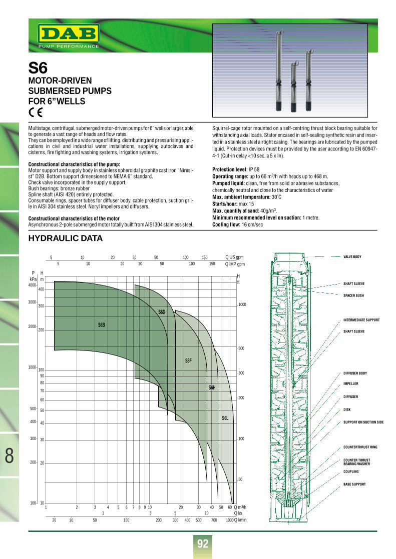
92
®
8
HYDRAULIC DATA
S6MOTOR-DRIVENSUBMERSED PUMPSFOR 6”WELLS
Multistage, centrifugal, submerged motor-driven pumps for 6” wells or larger, ableto generate a vast range of heads and flow rates.They can be employed in a wide range of lifting, distributing and pressurising appli-cations in civil and industrial water installations, supplying autoclaves andcisterns, fire fighting and washing systems, irrigation systems.
Constructional characteristics of the pump:Motor support and supply body in stainless spheroidal graphite cast iron “Niresi-st” D2B. Bottom support dimensioned to NEMA 6” standard.Check valve incorporated in the supply support.Bush bearings: bronze rubberSpline shaft (AISI 420) entirely protected.Consumable rings, spacer tubes for diffuser body, cable protection, suction gril-le in AISI 304 stainless steel. Noryl impellers and diffusers.
Constructional characteristics of the motorAsynchronous 2-pole submerged motor totally built from AISI 304 stainless steel.
Squirrel-cage rotor mounted on a self-centring thrust block bearing suitable forwithstanding axial loads. Stator encased in self-sealing synthetic resin and inser-ted in a stainless steel airtight casing. The bearings are lubricated by the pumpedliquid. Protection devices must be provided by the user according to EN 60947-4-1 (Cut-in delay <10 sec. a 5 x In).
Protection level: IP 58Operating range: up to 66 m3/h with heads up to 468 m.Pumped liquid: clean, free from solid or abrasive substances,chemically neutral and close to the characteristics of waterMax. ambient temperature: 30˚CStarts/hour: max 15Max. quantity of sand: 40g/m3.Minimum recommended level on suction: 1 metre.Cooling flow: 16 cm/sec
1 2 3 4 5 6 7 8 9 10 20 30 40 50 60 Q m3/hQ l/sQ l/min50
1 3 5 10
100 200 300 400 500 700 1000
10
20
30
40
50
60
70
80
90100
200
300
400
Q IMP gpmQ US gpm
Hm
Hft
PkPa
55
100
200
300
400
500
1000
2000
3000
4000
50
100
200
300
500
1000
10 20 30 50 100 15010 20 30 50 100 150
3020
S6B
S6D
S6F
S6L
S6H
VALVE BODY
SHAFT SLEEVE
SPACER BUSH
INTERMEDIATE SUPPORT
SHAFT SLEEVE
DIFFUSER BODY
IMPELLER
DIFFUSER
DISK
SUPPORT ON SUCTION SIDE
COUNTERTHRUST RING
COUNTER THRUSTBEARING WASHER
COUPLING
BASE SUPPORT
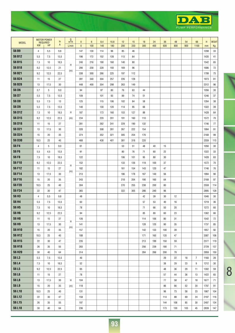
®
93
8
H
(m)
H
(m)
H
(m)
H
(m)
S6 B9 4 5,5 9,8 147 130 114 96 85 46 1208 33
S6 B12 5,5 7,5 13,5 196 172 152 128 113 64 1435 41
S6 B15 7,5 10 18,5 240 216 190 160 140 80 1542 65
S6 B18 9,2 12,5 21 290 258 228 193 169 96 1686 72
S6 B21 9,2 12,5 22,5 338 300 266 225 197 112 1799 75
S6 B24 11 15 27 391 340 304 257 226 128 1973 81
S6 B28 13 17,5 30 448 400 354 298 263 149 2312 96
S6 D6 3,7 5 9,0 94 87 80 76 63 44 1056 30
S6 D7 5,5 7,5 12,5 109 101 93 89 74 51 1246 37
S6 D8 5,5 7,5 13 125 115 106 102 84 58 1284 38
S6 D9 5,5 7,5 13,5 140 130 120 114 95 66 1322 39
S6 D12 7,5 10 18,5 187 173 160 153 127 88 1428 64
S6 D15 9,2 12,5 22,5 234 220 201 191 160 110 1572 70
S6 D18 11 15 27 281 262 241 229 190 132 1746 77
S6 D21 13 17,5 30 328 308 281 267 222 154 1994 91
S6 D24 15 20 35 374 352 321 305 254 176 2168 99
S6 D30 18,5 25 40 468 438 401 381 318 220 2559 115
S6 F4 4 5 9,0 61 53 51 48 40 15 1056 30
S6 F6 5,5 4,5 13,5 91 80 76 71 60 22 1322 33
S6 F8 7,5 10 18,5 122 106 101 95 80 30 1428 63
S6 F10 9,2 12,5 22,5 152 133 126 119 100 37 1572 70
S6 F12 11 15 27 182 161 154 143 120 47 1746 76
S6 F14 13 17,5 30 213 186 178 167 140 56 1994 90
S6 F16 15 20 35 243 218 204 190 160 64 2168 97
S6 F20 18,5 25 40 304 270 255 238 200 80 2559 114
S6 F24 22 30 47 365 322 305 286 240 96 2895 128
S6 H3 4 5,5 9,8 48 42 39 30 12 1046 30
S6 H4 5,5 7,5 13,5 63 57 53 40 16 1219 36
S6 H5 7,5 10 18,5 78 71 66 50 20 1272 60
S6 H6 9,2 12,5 22,5 94 85 80 60 23 1362 66
S6 H8 11 15 27 126 114 106 80 31 1542 72
S6 H9 13 17,5 30 141 128 120 90 35 1737 85
S6 H10 15 20 35 157 142 133 100 39 1857 92
S6 H12 18,5 25 40 188 171 160 120 47 2087 106
S6 H15 22 30 47 235 213 199 150 59 2377 119
S6 H18 26 35 55 283 256 239 180 71 2729 137
S6 H20 30 40 64 314 284 266 200 78 2959 150
S6 L3 5,5 7,5 13,5 40 29 22 18 7 1160 28
S6 L4 7,5 10 18,5 52 38 29 23 9 1212 30
S6 L5 9,2 12,5 22,5 65 48 36 29 11 1302 59
S6 L6 11 15 27 78 57 44 36 13 1422 65
S6 L8 13 17,5 30 104 77 58 47 18 1677 71
S6 L9 15 20 35 118 86 66 52 20 1797 91
S6 L10 18,5 25 40 131 96 73 58 23 1967 104
S6 L12 22 30 47 158 114 88 69 24 2197 116
S6 L15 26 35 55 197 144 108 85 30 2497 134
S6 L18 30 40 64 236 173 130 103 45 2839 147
MODELMOTOR POWER
REQUIREDKW HP
H
(m)
0 6 8,4 10,8 12 15 18 24 36 48 54 66 H WEIGHT0 100 140 180 200 250 300 400 600 800 900 1100 mm Kg
Qm3/hL/min
lnA
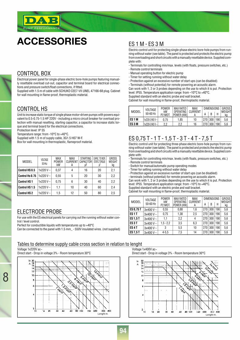
94
8
®
ACCESSORIES
CONTROL BOXElectrical power panel for single-phase electric bore-hole pumps featuring manual-ly resettable overload cut-out, capacitor and terminal board for electrical connec-tions and pressure switch/float connections, if fitted. Supplied with 1.5 m of cable with SCHUKO CEE7-VII UNEL 47166-68 plug. Cabinetfor wall mounting in flame-proof, thermoplastic material.
ES 1 M - ES 3 MElectric control unit for protecting single-phase electric bore-hole pumps from run-ning without water (see table). The panel is protected and protects the electric pumpfrom overloading and short circuits with a manually resettable device. Supplied com-plete with:- Terminals for controlling min/max. levels (with floats, pressure switches, etc.)- Remote control terminals- Manual operating button for electric pump- Timer for setting running without water delay- Protection against an excessive number of start ups (can be disabled)- Terminals (without potential) for remote powering an acoustic alarm.Can work with 1, 2 or 3 probes depending on the use to which it is put. Protectionlevel: IP55. Temperature application range: from –10°C to +40°C.Supplied standard with an electric probe and wall bracket.Cabinet for wall mounting in flame-proof, thermoplastic material.
ES 0,75 T - 1 T - 1,5 T - 3 T - 4 T - 7,5 TElectric control unit for protecting three-phase electric bore-hole pumps from run-ning without water (see table). The panel is protected and protects the electric pumpfrom overloading and short circuits with a manually resettable device. Supplied com-plete with:- Terminals for controlling min/max. levels (with floats, pressure switches, etc.)- Remote control terminals- Switch for manual/automatic pump operating modes- Timer for setting running without water delay- Protection against an excessive number of start ups (can be disabled)- terminals (without potential) for remote powering an acoustic alarm.Can work with 1, 2 or 3 probes depending on the use to which it is put. Protectionlevel: IP55. Temperature application range: from –10°C to +40°C.Supplied standard with an electric probe and wall bracket.Cabinet for wall mounting in flame-proof, thermoplastic material.
CONTROL HSUnit to increase static torque of single phase motor-driven pumps with powers equi-valent to 0.5-0.75-1.5 HP 220V - including a micro circuit breaker for overload pro-tection with manual resetting, starting capacitor, a capacitor to increase static tor-que and terminal board for the electrical connections.Protection level: IP 55Temperature range: from -10°C to +40°C.Supplied with 1.5 m of supply cable, 3G1.5 H07 W-F.Box for wall mounting in thermoplastic, flameproof material.
ELECTRODE PROBEFor use with the ES electrical panels for carrying out the running without water con-trol / level control.Perfect for conductible liquids with temperatures up to +40°CCan be connected to the panel with 1.5 mm_ - 550V insulated wires. (not supplied)
Tables to determine supply cable cross section in relation to lenght Voltage 1x220V ac~ Voltage 1x400V ac~Direct start - Drop in voltage 3% - Room temperature 30°C Direct start - Drop in voltage 3% - Room temperature 30°C
MODEL
ES 1 MES 3 M
VOLTAGE50-60 Hz
1x220-240 V�1x220-240 V�
0,752,2
1,852,2
1016
270270
300300
190190
5,65,6
POWER kW
P2 MOT.
MAX RATED OPERATING
POWER (KW)
GROSSWEIGHT
kg
MAXCURRENT
A
DIMENSIONS
A B H
MODEL
ES 0,75 TES 1 TES 1,5 TES 3 TES 4 TES 7,5 T
VOLTAGE50-60 Hz
3x400 V�3x400 V�3x400 V�3x400 V�3x400 V�3x400 V�
0,550,751,1
1,5 - 2,23
4-5,5
0,881,382,23,55,57,5
1,62,54
6,31014
270270270270270270
300300300300300300
190190190190190190
5,65,65,65,65,65,6
POWER kW
P2 MOT.
MAX RATED OPERATING
POWER (KW)
GROSSWEIGHT
kg
MAXCURRENT
A
DIMENSIONS
A B H
MODEL
Control HS 0.5
Control Hs 0.75
Control HS 1
Control HS 1.5
Control HS 2
VOLTAGE50 Hz
1x220 V�
1x220 V�
1x220 V�
1x220 V�
1x220 V�
0,37
0,55
0,75
1,1
1,5
4
5
6
10
12
16
20
30
40
50
20
30
40
60
80
2,1
2,2
2,2
2,4
2,5
MAXPOWER
kW
MAXCURRENT
A
STARTINGCAPACITOR
µF
CAPAC. TO INCR.STATIC TORQUE
µF
GROSSWEIGHT
kg
Lenght m. Lenght m.
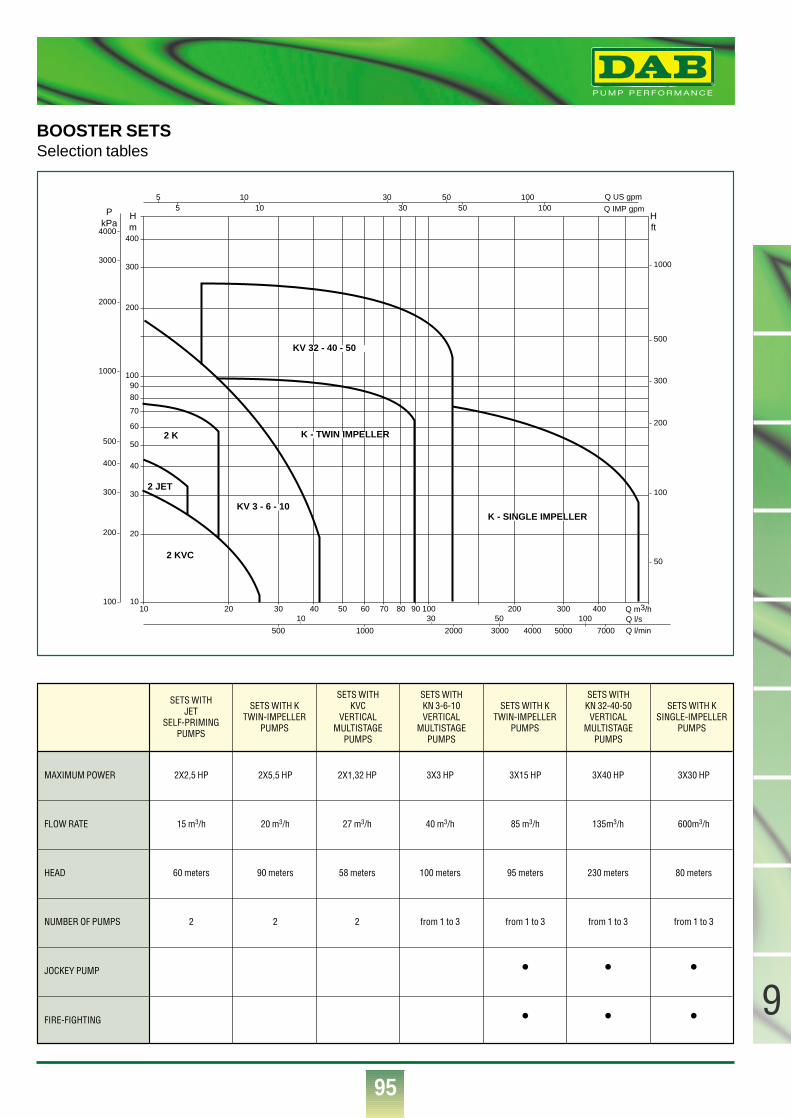
95
9
®
BOOSTER SETSSelection tables
10 20 30 40 50 60 70 80 90 100 200 300 400 Q m3/hQ l/sQ l/min500
10 30 50 100
1000 2000 3000 4000 5000 7000
10
20
30
40
50
60
70
80
90100
200
300
400
Q IMP gpm
Q US gpm
Hm
Hft
PkPa
55
100
200
300
400
500
1000
2000
3000
4000
50
100
200
300
500
1000
10 30 50 10010 30 50 100
2 JET
2 K
2 KVC
KV 3 - 6 - 10
K - TWIN IMPELLER
KV 32 - 40 - 50
K - SINGLE IMPELLER
SETS WITHJET
SELF-PRIMINGPUMPS
SETS WITH KTWIN-IMPELLER
PUMPS
SETS WITHKVC
VERTICALMULTISTAGE
PUMPS
SETS WITHKN 3-6-10VERTICAL
MULTISTAGEPUMPS
SETS WITH KTWIN-IMPELLER
PUMPS
SETS WITHKN 32-40-50VERTICAL
MULTISTAGEPUMPS
SETS WITH KSINGLE-IMPELLER
PUMPS
MAXIMUM POWER 2X2,5 HP 2X5,5 HP 2X1,32 HP 3X3 HP 3X15 HP 3X40 HP 3X30 HP
FLOW RATE 15 m3/h 20 m3/h 27 m3/h 40 m3/h 85 m3/h 135m3/h 600m3/h
HEAD 60 meters 90 meters 58 meters 100 meters 95 meters 230 meters 80 meters
NUMBER OF PUMPS 2 2 2 from 1 to 3 from 1 to 3 from 1 to 3 from 1 to 3
• • •
• • •
JOCKEY PUMP
FIRE-FIGHTING
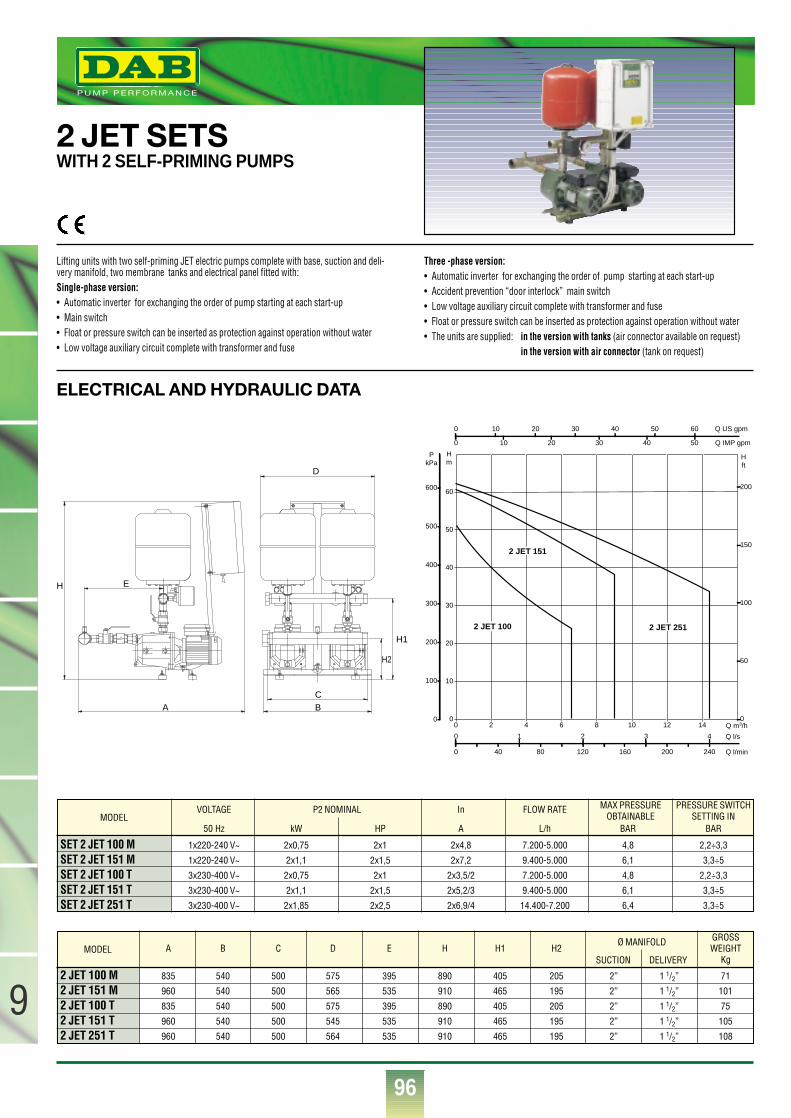
96
9
®
ELECTRICAL AND HYDRAULIC DATA
2 JET SETSWITH 2 SELF-PRIMING PUMPS
Lifting units with two self-priming JET electric pumps complete with base, suction and deli-very manifold, two membrane tanks and electrical panel fitted with:Single-phase version:• Automatic inverter for exchanging the order of pump starting at each start-up• Main switch• Float or pressure switch can be inserted as protection against operation without water• Low voltage auxiliary circuit complete with transformer and fuse
Three -phase version:• Automatic inverter for exchanging the order of pump starting at each start-up• Accident prevention “door interlock” main switch• Low voltage auxiliary circuit complete with transformer and fuse• Float or pressure switch can be inserted as protection against operation without water• The units are supplied: in the version with tanks (air connector available on request)
in the version with air connector (tank on request)
SET 2 JET 100 M 1x220-240 V~ 2x0,75 2x1 2x4,8 7.200-5.000 4,8 2,2÷3,3
SET 2 JET 151 M 1x220-240 V~ 2x1,1 2x1,5 2x7,2 9.400-5.000 6,1 3,3÷5
SET 2 JET 100 T 3x230-400 V~ 2x0,75 2x1 2x3,5/2 7.200-5.000 4,8 2,2÷3,3
SET 2 JET 151 T 3x230-400 V~ 2x1,1 2x1,5 2x5,2/3 9.400-5.000 6,1 3,3÷5
SET 2 JET 251 T 3x230-400 V~ 2x1,85 2x2,5 2x6,9/4 14.400-7.200 6,4 3,3÷5
VOLTAGE P2 NOMINAL In FLOW RATE
50 Hz kW HP A L/h BAR BAR
MAX PRESSUREOBTAINABLE
PRESSURE SWITCHSETTING INMODEL
2 JET 100 M 835 540 500 575 395 890 405 205 2” 1 1/2” 71
2 JET 151 M 960 540 500 565 535 910 465 195 2” 1 1/2” 101
2 JET 100 T 835 540 500 575 395 890 405 205 2” 1 1/2” 75
2 JET 151 T 960 540 500 545 535 910 465 195 2” 1 1/2” 105
2 JET 251 T 960 540 500 564 535 910 465 195 2” 1 1/2” 108
A B C D E H H1 H2GROSSWEIGHT
Kg
Ø MANIFOLD
SUCTION DELIVERYMODEL
A BC
H1
D
H2
EH
0 2 4 6 8 10 12 14 Q m3/h0
10
20
30
40
50
60
Hm
0
100
200
300
400
500
600
PkPa
0 40 80 120 160 200 240 Q l/min
0 1 2 3 4 Q l/s
0
50
100
150
200
H ft
0 10 20 30 40 50 60 Q US gpm
0 10 20 30 40 50 Q IMP gpm
2 JET 100
2 JET 151
2 JET 251
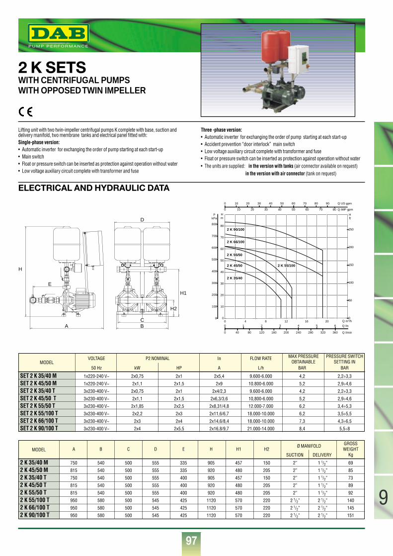
97
9
®
ELECTRICAL AND HYDRAULIC DATA
2 K SETSWITH CENTRIFUGAL PUMPSWITH OPPOSED TWIN IMPELLER
Lifting unit with two twin-impeller centrifugal pumps K complete with base, suction anddelivery manifold, two membrane tanks and electrical panel fitted with:Single-phase version:• Automatic inverter for exchanging the order of pump starting at each start-up • Main switch• Float or pressure switch can be inserted as protection against operation without water• Low voltage auxiliary circuit complete with transformer and fuse
Three -phase version:• Automatic inverter for exchanging the order of pump starting at each start-up• Accident prevention “door interlock” main switch• Low voltage auxiliary circuit complete with transformer and fuse• Float or pressure switch can be inserted as protection against operation without water• The units are supplied: in the version with tanks (air connector available on request)
in the version with air connector (tank on request)
SET 2 K 35/40 M 1x220-240 V~ 2x0,75 2x1 2x5,4 9.600-6.000 4,2 2,2÷3,3
SET 2 K 45/50 M 1x220-240 V~ 2x1,1 2x1,5 2x9 10.800-6.000 5,2 2,9÷4,6
SET 2 K 35/40 T 3x230-400 V~ 2x0,75 2x1 2x4/2,3 9.600-6.000 4,2 2,2÷3,3
SET 2 K 45/50 T 3x230-400 V~ 2x1,1 2x1,5 2x6,3/3,6 10,800-6.000 5,2 2,9÷4,6
SET 2 K 55/50 T 3x230-400 V~ 2x1,85 2x2,5 2x8,31/4,8 12.000-7.000 6,2 3,4÷5,3
SET 2 K 55/100 T 3x230-400 V~ 2x2,2 2x3 2x11,6/6,7 18.000-10.000 6,2 3,5÷5,5
SET 2 K 66/100 T 3x230-400 V~ 2x3 2x4 2x14,6/8,4 18.000-10.000 7,3 4,3÷6,5
SET 2 K 90/100 T 3x230-400 V~ 2x4 2x5,5 2x16,8/9,7 21.000-14.000 8,4 5,5÷8
VOLTAGE P2 NOMINAL In FLOW RATE
50 Hz kW HP A L/h BAR BAR
MAX PRESSUREOBTAINABLE
PRESSURE SWITCHSETTING IN
2 K 35/40 M 750 540 500 555 335 905 457 150 2” 1 1/2” 69
2 K 45/50 M 815 540 500 555 335 920 480 205 2” 1 1/2” 85
2 K 35/40 T 750 540 500 555 400 905 457 150 2” 1 1/2” 73
2 K 45/50 T 815 540 500 555 400 920 480 205 2” 1 1/2” 89
2 K 55/50 T 815 540 500 555 400 920 480 205 2” 1 1/2” 92
2 K 55/100 T 950 580 500 545 425 1120 570 220 2 1/2” 2 1/2” 140
2 K 66/100 T 950 580 500 545 425 1120 570 220 2 1/2” 2 1/2” 145
2 K 90/100 T 950 580 500 545 425 1120 570 220 2 1/2” 2 1/2” 151
A B C D E H H1 H2GROSSWEIGHT
Kg
Ø MANIFOLD
SUCTION DELIVERY
MODEL
MODEL
A B
H1
C
D
H
E
H2
Q m3/h0
10
20
30
40
50
60
70
80
Hm
0
100
200
300
400
500
600
700
800
PkPa
0 40 80 120 160 200 240 280 320 360 Q l/min
0 1 2 3 4 5 60 4 8 12 16 20
Q l/s
0
50
100
150
200
250
H ft
0 10 20 30 40 50 60 70 80 90 Q US gpm
0 10 20 30 40 50 60 70 80 Q IMP gpm
2 K 45/50
2 K 66/100
2 K 35/40
2 K 90/100
2 K 55/50
2 K 55/100
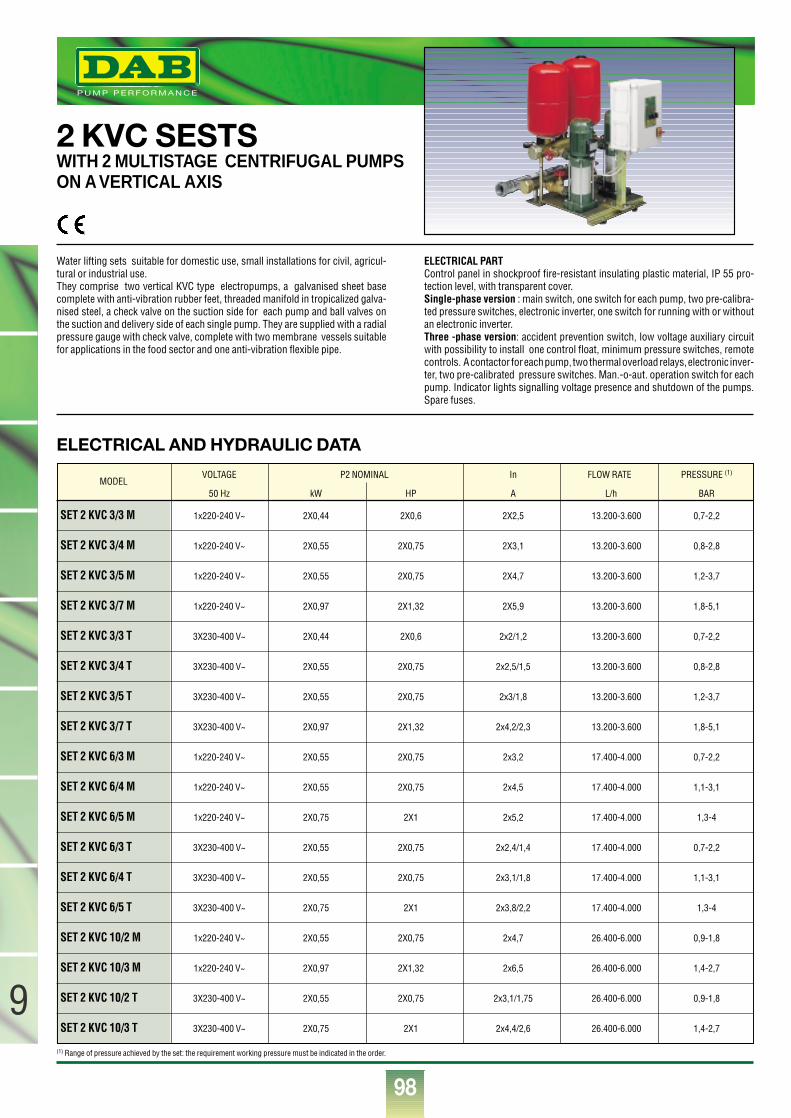
98
9
®
ELECTRICAL AND HYDRAULIC DATA
2 KVC SESTSWITH 2 MULTISTAGE CENTRIFUGAL PUMPS ON A VERTICAL AXIS
Water lifting sets suitable for domestic use, small installations for civil, agricul-tural or industrial use.They comprise two vertical KVC type electropumps, a galvanised sheet basecomplete with anti-vibration rubber feet, threaded manifold in tropicalized galva-nised steel, a check valve on the suction side for each pump and ball valves onthe suction and delivery side of each single pump. They are supplied with a radialpressure gauge with check valve, complete with two membrane vessels suitablefor applications in the food sector and one anti-vibration flexible pipe.
ELECTRICAL PARTControl panel in shockproof fire-resistant insulating plastic material, IP 55 pro-tection level, with transparent cover. Single-phase version : main switch, one switch for each pump, two pre-calibra-ted pressure switches, electronic inverter, one switch for running with or withoutan electronic inverter.Three -phase version: accident prevention switch, low voltage auxiliary circuitwith possibility to install one control float, minimum pressure switches, remotecontrols. A contactor for each pump, two thermal overload relays, electronic inver-ter, two pre-calibrated pressure switches. Man.-o-aut. operation switch for eachpump. Indicator lights signalling voltage presence and shutdown of the pumps.Spare fuses.
SET 2 KVC 3/3 M 1x220-240 V~ 2X0,44 2X0,6 2X2,5 13.200-3.600 0,7-2,2
SET 2 KVC 3/4 M 1x220-240 V~ 2X0,55 2X0,75 2X3,1 13.200-3.600 0,8-2,8
SET 2 KVC 3/5 M 1x220-240 V~ 2X0,55 2X0,75 2X4,7 13.200-3.600 1,2-3,7
SET 2 KVC 3/7 M 1x220-240 V~ 2X0,97 2X1,32 2X5,9 13.200-3.600 1,8-5,1
SET 2 KVC 3/3 T 3X230-400 V~ 2X0,44 2X0,6 2x2/1,2 13.200-3.600 0,7-2,2
SET 2 KVC 3/4 T 3X230-400 V~ 2X0,55 2X0,75 2x2,5/1,5 13.200-3.600 0,8-2,8
SET 2 KVC 3/5 T 3X230-400 V~ 2X0,55 2X0,75 2x3/1,8 13.200-3.600 1,2-3,7
SET 2 KVC 3/7 T 3X230-400 V~ 2X0,97 2X1,32 2x4,2/2,3 13.200-3.600 1,8-5,1
SET 2 KVC 6/3 M 1x220-240 V~ 2X0,55 2X0,75 2x3,2 17.400-4.000 0,7-2,2
SET 2 KVC 6/4 M 1x220-240 V~ 2X0,55 2X0,75 2x4,5 17.400-4.000 1,1-3,1
SET 2 KVC 6/5 M 1x220-240 V~ 2X0,75 2X1 2x5,2 17.400-4.000 1,3-4
SET 2 KVC 6/3 T 3X230-400 V~ 2X0,55 2X0,75 2x2,4/1,4 17.400-4.000 0,7-2,2
SET 2 KVC 6/4 T 3X230-400 V~ 2X0,55 2X0,75 2x3,1/1,8 17.400-4.000 1,1-3,1
SET 2 KVC 6/5 T 3X230-400 V~ 2X0,75 2X1 2x3,8/2,2 17.400-4.000 1,3-4
SET 2 KVC 10/2 M 1x220-240 V~ 2X0,55 2X0,75 2x4,7 26.400-6.000 0,9-1,8
SET 2 KVC 10/3 M 1x220-240 V~ 2X0,97 2X1,32 2x6,5 26.400-6.000 1,4-2,7
SET 2 KVC 10/2 T 3X230-400 V~ 2X0,55 2X0,75 2x3,1/1,75 26.400-6.000 0,9-1,8
SET 2 KVC 10/3 T 3X230-400 V~ 2X0,75 2X1 2x4,4/2,6 26.400-6.000 1,4-2,7
VOLTAGE P2 NOMINAL In FLOW RATE PRESSURE (1)
50 Hz kW HP A L/h BARMODEL
(1) Range of pressure achieved by the set: the requirement working pressure must be indicated in the order.
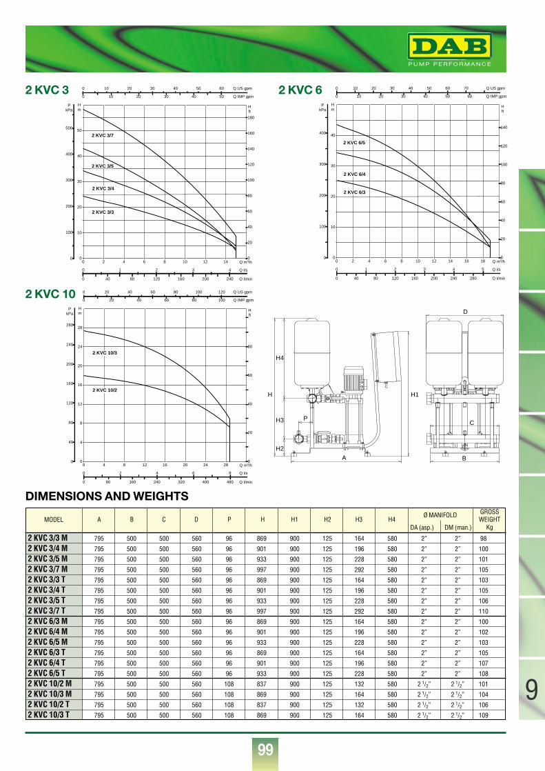
99
9
®
0 Q m3/h2 4 6 8 10 12 140
10
20
30
40
50
Hm
0
100
200
300
400
500
PkPa
0 40 80 120 160 200 240 Q l/min
0 1 2 3 4 Q l/s
0
20
40
60
80
100
120
140
160
180
H ft
0 10 20 30 40 50 60 Q US gpm
0 10 20 30 40 50 Q IMP gpm
2 KVC 3/7
2 KVC 3/5
2 KVC 3/4
2 KVC 3/3
DIMENSIONS AND WEIGHTS
2 KVC 3
0 Q m3/h2 4 6 8 10 12 14 16 180
10
20
30
40
Hm
0
100
200
300
400
PkPa
0 40 80 120 160 200 240 280 Q l/min
0 1 2 3 4 5 Q l/s
0
20
40
60
80
100
120
140
H ft
0 10 20 30 40 50 60 70 Q US gpm
0 10 20 30 40 50 60 Q IMP gpm
2 KVC 6/5
2 KVC 6/4
2 KVC 6/3
2 KVC 6
0 Q m3/h4 8 12 16 20 24 280
4
8
12
16
20
24
28
Hm
0
40
80
120
160
200
240
280
PkPa
0 80 160 240 320 400 480 Q l/min
0 2 4 6 8 Q l/s
0
20
40
60
80
H ft
0 20 40 60 80 100 120 Q US gpm
0 20 40 60 80 100 Q IMP gpm
2 KVC 10/3
2 KVC 10/2
2 KVC 10
A
P
H2
H3
H4
H H1
B
C
D
2 KVC 3/3 M 795 500 500 560 96 869 900 125 164 580 2” 2” 98
2 KVC 3/4 M 795 500 500 560 96 901 900 125 196 580 2” 2” 100
2 KVC 3/5 M 795 500 500 560 96 933 900 125 228 580 2” 2” 101
2 KVC 3/7 M 795 500 500 560 96 997 900 125 292 580 2” 2” 105
2 KVC 3/3 T 795 500 500 560 96 869 900 125 164 580 2” 2” 103
2 KVC 3/4 T 795 500 500 560 96 901 900 125 196 580 2” 2” 105
2 KVC 3/5 T 795 500 500 560 96 933 900 125 228 580 2” 2” 106
2 KVC 3/7 T 795 500 500 560 96 997 900 125 292 580 2” 2” 110
2 KVC 6/3 M 795 500 500 560 96 869 900 125 164 580 2” 2” 100
2 KVC 6/4 M 795 500 500 560 96 901 900 125 196 580 2” 2” 102
2 KVC 6/5 M 795 500 500 560 96 933 900 125 228 580 2” 2” 103
2 KVC 6/3 T 795 500 500 560 96 869 900 125 164 580 2” 2” 105
2 KVC 6/4 T 795 500 500 560 96 901 900 125 196 580 2” 2” 107
2 KVC 6/5 T 795 500 500 560 96 933 900 125 228 580 2” 2” 108
2 KVC 10/2 M 795 500 500 560 108 837 900 125 132 580 2 1/2” 2 1/2” 101
2 KVC 10/3 M 795 500 500 560 108 869 900 125 164 580 2 1/2” 2 1/2” 104
2 KVC 10/2 T 795 500 500 560 108 837 900 125 132 580 2 1/2” 2 1/2” 106
2 KVC 10/3 T 795 500 500 560 108 869 900 125 164 580 2 1/2” 2 1/2” 109
A B C D P H H1 H2 H3 H4GROSSWEIGHT
Kg
Ø MANIFOLD
DA (asp.) DM (man.)MODEL
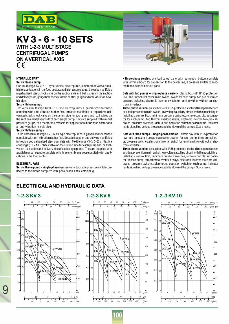
100
9
®
ELECTRICAL AND HYDRAULIC DATA
1-2-3 KV 3 1-2-3 KV 6
KV 3 - 6 - 10 SETSWITH 1-2-3 MULTISTAGE CENTRIFUGAL PUMPSON A VERTICAL AXIS
HYDRAULIC PARTSets with one pumpOne multistage KV 3-6-10 type vertical electropump, a membrane vessel suita-ble for applications in the food sector, a radial pressure gauge, threaded manifoldsin galvanised steel, check valve on the suction side and ball valves on the suctionand delivery side, gauge holder cock for the control gauge and anti-vibration flexi-ble pipe.Sets with two pumpsTwo vertical multistage KV 3-6-10 type electropumps, a galvanised sheet basecomplete with anti-vibration rubber feet, threaded manifolds in tropicalized gal-vanised steel, check valve on the suction side for each pump and ball valves onthe suction and delivery side of each single pump. They are supplied with a radialpressure gauge, two membrane vessels for applications in the food sector andan anti-vibration flexible pipe.Sets with three pumpsThree vertical multistage KV 3-6-10 type electropumps, a galvanised sheet basecomplete with anti-vibration rubber feet, threaded suction and delivery manifoldsin tropicalized galvanised steel complete with flexible pipe (3KV 3-6) or flexiblecouplings (3 KV 10 ), check valve on the suction side for each pump and ball val-ves on the suction and delivery side of each single pump. They are supplied witha radial pressure gauge complete with three membrane vessels suitable for appli-cations in the food sector.
ELECTRICAL PARTSets with one pump - single-phase version – one two-pole pressure switch con-nected to the motor, complete with power cable and electric plug.
• Three-phase version: overload cutout panel with rearm push button, completewith terminal board for connection to the power line, 1 pressure switch connec-ted to the overload cutout panel.
Sets with two pumps – single-phase version- plastic box with IP 55 protectionlevel and transparent cover, main switch, switch for each pump, two pre-calibratedpressure switches, electronic inverter, switch for running with or without an elec-tronic inverter. - Three-phase version: plastic box with IP 55 protection level and transparent cover,accident prevention main switch, low voltage auxiliary circuit with the possibility ofinstalling a control float, minimum pressure switches, remote controls. A contac-tor for each pump, two thermal overload relays, electronic inverter, two pre-cali-brated pressure switches. Man.-o-aut. operation switch for each pump. Indicatorlights signalling voltage presence and shutdown of the pumps. Spare fuses.
Sets with three pumps – single-phase version- plastic box with IP 55 protectionlevel and transparent cover, main switch, switch for each pump, three pre-calibra-ted pressure switches, electronic inverter, switch for running with or without an elec-tronic inverter. - Three-phase version: plastic box with IP 55 protection level and transparent cover,accident prevention main switch, low voltage auxiliary circuit with the possibility ofinstalling a control float, minimum pressure switches, remote controls. A contac-tor for each pump, three thermal overload relays, electronic inverter, three pre-cali-brated pressure switches. Man.-o-aut. operation switch for each pump. Indicatorlights signalling voltage presence and shutdown of the pumps. Spare fuses.
0 Q m3/h3 6 9 12 15 18 210
20
40
60
80
100
120
140
160
180
Hm
0
200
400
600
800
1000
1200
1400
1600
1800
PkPa
0 60 120 180 240 300 360 Q l/min
0 1,5 3 4,5 6 Q l/s
0
100
200
300
400
500
600
H ft
0 15 30 45 60 75 90 Q US gpm
0 15 30 45 60 75 Q IMP gpm
1KV 3/18
1KV 3/15
1KV 3/12
1KV 3/10
2 KV 3/18
3 KV 3/182 KV 3/15
3 KV 3/15
2 KV 3/12
3 KV 3/122 KV 3/10
3 KV 3/10
0 Q m3/h3 6 9 12 15 18 21 24 270
20
40
60
80
100
120
Hm
0
200
400
600
800
1000
1200
PkPa
0 60 120 180 240 300 360 420 Q l/min
0 1,5 3 4,5 6 7,5 Q l/s
0
50
100
150
200
250
300
350
400
H ft
0 15 30 45 60 75 90 105 Q US gpm
0 15 30 45 60 75 90 Q IMP gpm
1 KV 6/15
2 KV 6/153 KV 6/15
1 KV 6/11
2 KV 6/113 KV 6/111 KV 6/9
2 KV 6/9 3 KV 6/9
1 KV 6/7
2 KV 6/73 KV 6/7
1-2-3 KV 10
0 Q m3/h6 12 18 24 30 36 420
10
20
30
40
50
60
70
Hm
0
100
200
300
400
500
600
700
PkPa
0 120 240 360 480 600 720 Q l/min
0 3 6 9 12 Q l/s
0
40
80
120
160
200
240
H ft
0 30 60 90 120 150 180 Q US gpm
0 30 60 90 120 150 Q IMP gpm
1 KV 10/8
1 KV 10/6
1 KV 10/5
1 KV 10/4
2 KV 10/8
3 KV 10/8
2 KV 10/6
3 KV 10/62 KV 10/5
3 KV 10/5
2 KV 10/4
3 KV 10/4
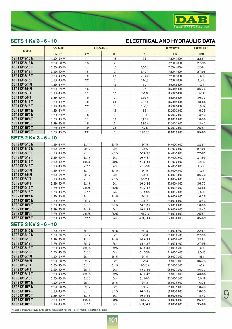
101
9
®
(1) Range of pressure achieved by the set: the requirement working pressure must be indicated in the order.
ELECTRICAL AND HYDRAULIC DATA
SET 1 KV 3/10 M 1x220-240 V~ 1,1 1,5 7,8 7.200-1.800 2,2÷8,1
SET 1 KV 3/12 M 1x220-240 V~ 1,5 2 9,6 7.200-1.800 2,7÷9,5
SET 1 KV 3/10 T 3x230-400 V~ 1,1 1,5 5,6-3,2 7.200-1.800 2,2÷8,1
SET 1 KV 3/12 T 3x230-400 V~ 1,5 2 6,4-3,7 7.200-1.800 2,7÷9,5
SET 1 KV 3/15 T 3x230-400 V~ 1,85 2,5 7,5-4,3 7.200-1.800 3,4÷12
SET 1 KV 3/18 T 3x230-400 V~ 2,2 3 10-5,8 7.200-1.800 4,8÷16
SET 1 KV 6/7 M 1x220-240 V~ 1,1 1,5 7,5 8.500-2.400 3÷5,8
SET 1 KV 6/9 M 1x220-240 V~ 1,5 2 9,4 8.500-2.400 3,6÷7,3
SET 1 KV 6/7 T 3x230-400 V~ 1,1 1,5 5-2,9 8.500-2.400 3÷5,8
SET 1 KV 6/9 T 3x230-400 V~ 1,5 2 6,2-3,6 8.500-2.400 3,6÷7,3
SET 1 KV 6/11 T 3x230-400 V~ 1,85 2,5 7,3-4,2 8.500-2.400 4,3÷8,8
SET 1 KV 6/15 T 3x230-400 V~ 2,2 3 11-6,3 8.500-2.400 6,4÷12
SET 1 KV 10/4 M 1x220-240 V~ 1,1 1,5 8,3 13.200-3.000 1,6÷3,5
SET 1 KV 10/5 M 1x220-240 V~ 1,5 2 10,4 13.200-3.000 1,8÷4,3
SET 1 KV 10/4 T 3x230-400 V~ 1,1 1,5 6,1-3,5 13.200-3.000 1,6÷3,5
SET 1 KV 10/5 T 3x230-400 V~ 1,5 2 6,8-3,9 13.200-3.000 1,8÷4,3
SET 1 KV 10/6 T 3x230-400 V~ 1,85 2,5 8,7-5 13.200-3.000 2,5÷5,1
SET 1 KV 10/8 T 3x230-400 V~ 2,2 3 11,8-6,8 13.200-3.000 3,5÷6,9
VOLTAGE P2 NOMINAL In FLOW RATE PRESSURE (1)
50 Hz kW HP A L/h BARMODEL
SET 2 KV 3/10 M 1x220-240 V~ 2x1,1 2x1,5 2x7,8 14.400-3.600 2,2÷8,1
SET 2 KV 3/12 M 1x220-240 V~ 2x1,5 2x2 2x9,6 14.400-3.600 2,7÷9,5
SET 2 KV 3/10 T 3x230-400 V~ 2x1,1 2x1,5 2x5,6-3,2 14.400-3.600 2,2÷8,1
SET 2 KV 3/12 T 3x230-400 V~ 2x1,5 2x2 2x6,4-3,7 14.400-3.600 2,7÷9,5
SET 2 KV 3/15 T 3x230-400 V~ 2x1,85 2x2,5 2x7,5-4,3 14.400-3.600 3,4÷12
SET 2 KV 3/18 T 3x230-400 V~ 2x2,2 2x3 2x10-5,8 14.400-3.600 4,8÷16
SET 2 KV 6/7 M 1x220-240 V~ 2x1,1 2x1,5 2x7,5 17.000-4.800 3÷5,8
SET 2 KV 6/9 M 1x220-240 V~ 2x1,5 2x2 2x9,4 17.000-4.800 3,6÷7,3
SET 2 KV 6/7 T 3x230-400 V~ 2x1,1 2x1,5 2x5-2,9 17.000-4.800 3÷5,8
SET 2 KV 6/9 T 3x230-400 V~ 2x1,5 2x2 2x6,2-3,6 17.000-4.800 3,6÷7,3
SET 2 KV 6/11 T 3x230-400 V~ 2x1,85 2x2,5 2x7,3-4,2 17.000-4.800 4,3÷8,8
SET 2 KV 6/15 T 3x230-400 V~ 2x2,2 2x3 2x11-6,3 17.000-4.800 6,4÷12
SET 2 KV 10/4 M 1x220-240 V~ 2x1,1 2x1,5 2x8,3 24.600-6.000 1,6÷3,5
SET 2 KV 10/5 M 1x220-240 V~ 2x1,5 2x2 2x10,4 24.600-6.000 1,8÷4,3
SET 2 KV 10/4 T 3x230-400 V~ 2x1,1 2x1,5 2x6,1-3,5 24.600-6.000 1,6÷3,5
SET 2 KV 10/5 T 3x230-400 V~ 2x1,5 2x2 2x6,8-3,9 24.600-6.000 1,8÷4,3
SET 2 KV 10/6 T 3x230-400 V~ 2x1,85 2x2,5 2x8,7-5 24.600-6.000 2,5÷5,1
SET 2 KV 10/8 T 3x230-400 V~ 2x2,2 2x3 2x11,8-6,8 24.600-6.000 3,5÷6,9
SET 3 KV 3/10 M 1x220-240 V~ 3x1,1 3x1,5 3x7,8 21.600-5.400 2,2÷8,1
SET 3 KV 3/12 M 1x220-240 V~ 3x1,5 3x2 3x9,6 21.600-5.400 2,7÷9,5
SET 3 KV 3/10 T 3x230-400 V~ 3x1,1 3x1,5 3x5,6-3,2 21.600-5.400 2,2÷8,1
SET 3 KV 3/12 T 3x230-400 V~ 3x1,5 3x2 3x6,4-3,7 21.600-5.400 2,7÷9,5
SET 3 KV 3/15 T 3x230-400 V~ 3x1,85 3x2,5 3x7,5-4,3 21.600-5.400 3,4÷12
SET 3 KV 3/18 T 3x230-400 V~ 3x2,2 3x3 3x10-5,8 21.600-5.400 4,8÷16
SET 3 KV 6/7 M 1x220-240 V~ 3x1,1 3x1,5 3x7,5 25.500-7.200 3÷5,8
SET 3 KV 6/9 M 1x220-240 V~ 3x1,5 3x2 3x9,4 25.500-7.200 3,6÷7,3
SET 3 KV 6/7 T 3x230-400 V~ 3x1,1 3x1,5 3x5-2,9 25.500-7.200 3÷5,8
SET 3 KV 6/9 T 3x230-400 V~ 3x1,5 3x2 3x6,2-3,6 25.500-7.200 3,6÷7,3
SET 3 KV 6/11 T 3x230-400 V~ 3x1,85 3x2,5 3x7,3-4,2 25.500-7.200 4,3÷8,8
SET 3 KV 6/15 T 3x230-400 V~ 3x2,2 3x3 3x11-6,3 25.500-7.200 6,4÷12
SET 3 KV 10/4 M 1x220-240 V~ 3x1,1 3x1,5 3x8,3 39.600-9.000 1,6÷3,5
SET 3 KV 10/5 M 1x220-240 V~ 3x1,5 3x2 3x10,4 39.600-9.000 1,8÷4,3
SET 3 KV 10/4 T 3x230-400 V~ 3x1,1 3x1,5 3x6,1-3,5 39.600-9.000 1,6÷3,5
SET 3 KV 10/5 T 3x230-400 V~ 3x1,5 3x2 3x6,8-3,9 39.600-9.000 1,8÷4,3
SET 3 KV 10/6 T 3x230-400 V~ 3x1,85 3x2,5 3x8,7-5 39.600-9.000 2,5÷5,1
SET 3 KV 10/8 T 3x230-400 V~ 3x2,2 3x3 3x11,8-6,8 39.600-9.000 3,5÷6,9
SETS 1 KV 3 - 6 - 10
SETS 2 KV 3 - 6 - 10
SETS 3 KV 3 - 6 - 10
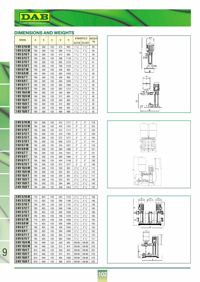
102
9
®
1 KV 3/10 M 760 300 120 473 993 1 1/4” 1 1/2” 39
1 KV 3/12 M 760 300 120 596 1116 1 1/4” 1 1/2” 40
1 KV 3/10 T 760 300 120 473 993 1 1/4” 1 1/2” 39
1 KV 3/12 T 760 300 120 596 1116 1 1/4” 1 1/2” 40
1 KV 3/15 T 760 300 120 692 1212 1 1/4” 1 1/2” 41
1 KV 3/18 T 760 300 120 788 1318 1 1/4” 1 1/2” 47
1 KV 6/7 M 760 300 120 436 956 1 1/4” 1 1/2” 37
1 KV 6/9 M 760 300 120 500 1020 1 1/4” 1 1/2” 40
1 KV 6/7 T 760 300 120 436 956 1 1/4” 1 1/2” 37
1 KV 6/9 T 760 300 120 500 1020 1 1/4” 1 1/2” 40
1 KV 6/11 T 760 300 120 564 1084 1 1/4” 1 1/2” 38
1 KV 6/15 T 760 300 120 692 1212 1 1/4” 1 1/2” 45
1 KV 10/4 M 760 300 120 340 860 1 1/4” 1 1/2” 35
1 KV 10/5 M 760 300 120 372 892 1 1/4” 1 1/2” 40
1 KV 10/4 T 760 300 120 340 860 1 1/4” 1 1/2” 35
1 KV 10/5 T 760 300 120 372 892 1 1/4” 1 1/2” 40
1 KV 10/6 T 760 300 120 404 920 1 1/4” 1 1/2” 38
1 KV 10/8 T 760 300 120 468 988 1 1/4” 1 1/2” 43
MODEL A B C D H WEIGHTKg
Ø MANIFOLD
SUCTION DELIVERY
2 KV 3/10 M 795 500 125 412 1117 2” 2” 118
2 KV 3/12 M 795 500 125 476 1181 2” 2” 124
2 KV 3/10 T 795 500 125 412 1117 2” 2” 123
2 KV 3/12 T 795 500 125 476 1181 2” 2” 129
2 KV 3/15 T 795 500 125 572 1277 2” 2” 134
2 KV 3/18 T 795 500 125 668 1373 2” 2” 141
2 KV 6/7 M 795 500 125 316 1021 2” 2” 116
2 KV 6/9 M 795 500 125 380 1085 2” 2” 121
2 KV 6/7 T 795 500 125 316 1021 2” 2” 121
2 KV 6/9 T 795 500 125 380 1085 2” 2” 126
2 KV 6/11 T 795 500 125 444 1149 2” 2” 128
2 KV 6/15 T 795 500 125 572 1277 2” 2” 140
2 KV 10/4 M 795 500 125 220 925 2 1/2” 2 1/2” 112
2 KV 10/5 M 795 500 125 252 957 2 1/2” 2 1/2” 115
2 KV 10/4 T 795 500 125 220 925 2 1/2” 2 1/2” 117
2 KV 10/5 T 795 500 125 252 957 2 1/2” 2 1/2” 120
2 KV 10/6 T 795 500 125 284 989 2 1/2” 2 1/2” 126
2 KV 10/8 T 795 500 125 348 1053 2 1/2” 2 1/2” 132
3 KV 3/10 M 710 825 120 532 1122 2 1/2” 2 1/2” 156
3 KV 3/12 M 710 825 120 596 1186 2 1/2” 2 1/2” 168
3 KV 3/10 T 785 825 120 532 1122 2 1/2” 2 1/2” 156
3 KV 3/12 T 785 825 120 596 1186 2 1/2” 2 1/2” 165
3 KV 3/15 T 785 825 120 692 1282 2 1/2” 2 1/2” 168
3 KV 3/18 T 785 825 120 788 1378 2 1/2” 2 1/2” 183
3 KV 6/7 M 710 825 120 436 1026 2 1/2” 2 1/2” 153
3 KV 6/9 M 710 825 120 500 1090 2 1/2” 2 1/2” 162
3 KV 6/7 T 785 825 120 436 1026 2 1/2” 2 1/2” 153
3 KV 6/9 T 785 825 120 500 1090 2 1/2” 2 1/2” 162
3 KV 6/11 T 785 825 120 564 1154 2 1/2” 2 1/2” 170
3 KV 6/15 T 785 825 120 692 1282 2 1/2” 2 1/2” 177
3 KV 10/4 M 740 940 120 340 942 DN 80 DN 80 201
3 KV 10/5 M 740 940 120 372 974 DN 80 DN 80 216
3 KV 10/4 T 810 940 120 340 942 DN 80 DN 80 201
3 KV 10/5 T 810 940 120 372 974 DN 80 DN 80 216
3 KV 10/6 T 810 940 120 404 1006 DN 80 DN 80 210
3 KV 10/8 T 810 940 120 468 1070 DN 80 DN 80 225
DIMENSIONS AND WEIGHTS
A
B
C
D
H
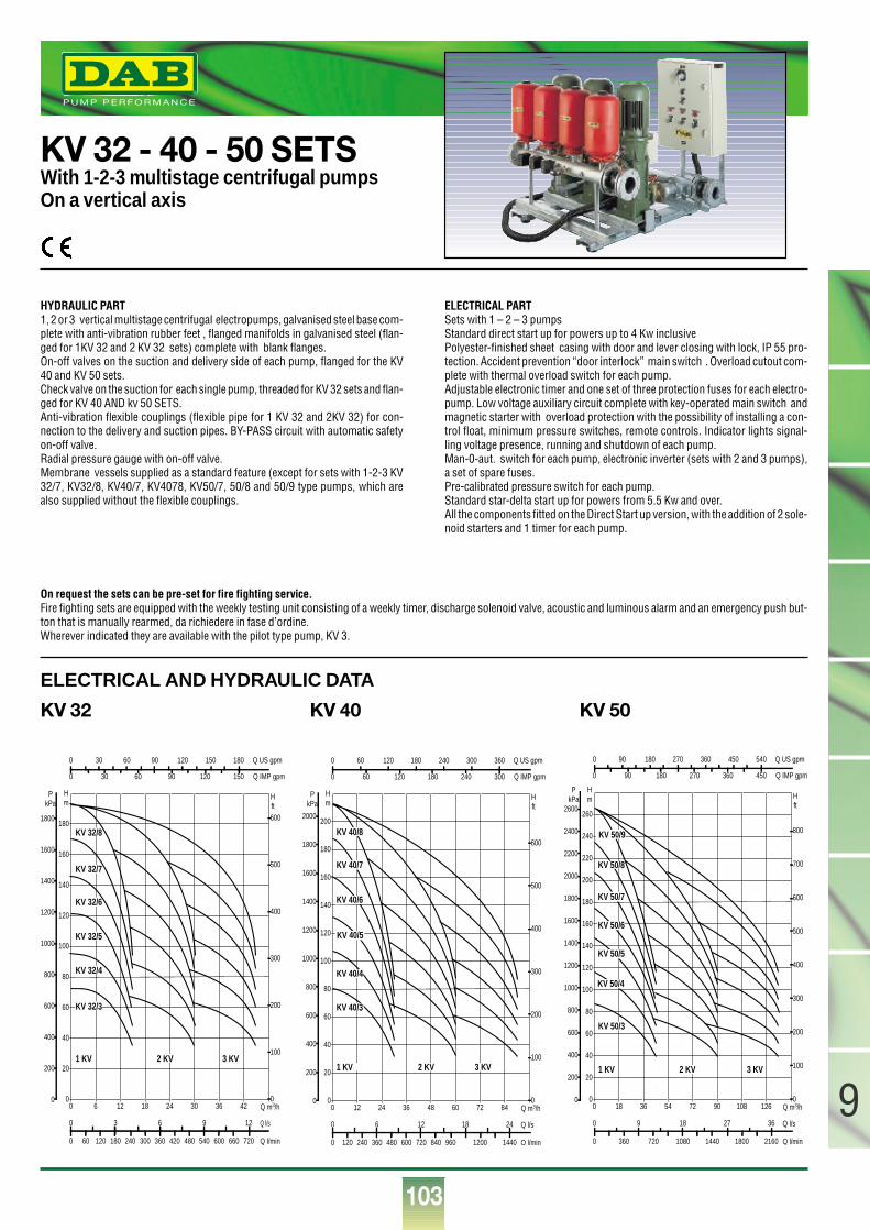
103
9
®
KV 32 - 40 - 50 SETSWith 1-2-3 multistage centrifugal pumpsOn a vertical axis
HYDRAULIC PART1, 2 or 3 vertical multistage centrifugal electropumps, galvanised steel base com-plete with anti-vibration rubber feet , flanged manifolds in galvanised steel (flan-ged for 1KV 32 and 2 KV 32 sets) complete with blank flanges. On-off valves on the suction and delivery side of each pump, flanged for the KV40 and KV 50 sets.Check valve on the suction for each single pump, threaded for KV 32 sets and flan-ged for KV 40 AND kv 50 SETS.Anti-vibration flexible couplings (flexible pipe for 1 KV 32 and 2KV 32) for con-nection to the delivery and suction pipes. BY-PASS circuit with automatic safetyon-off valve.Radial pressure gauge with on-off valve.Membrane vessels supplied as a standard feature (except for sets with 1-2-3 KV32/7, KV32/8, KV40/7, KV4078, KV50/7, 50/8 and 50/9 type pumps, which arealso supplied without the flexible couplings.
ELECTRICAL PART Sets with 1 – 2 – 3 pumpsStandard direct start up for powers up to 4 Kw inclusivePolyester-finished sheet casing with door and lever closing with lock, IP 55 pro-tection. Accident prevention “door interlock” main switch . Overload cutout com-plete with thermal overload switch for each pump.Adjustable electronic timer and one set of three protection fuses for each electro-pump. Low voltage auxiliary circuit complete with key-operated main switch andmagnetic starter with overload protection with the possibility of installing a con-trol float, minimum pressure switches, remote controls. Indicator lights signal-ling voltage presence, running and shutdown of each pump.Man-0-aut. switch for each pump, electronic inverter (sets with 2 and 3 pumps),a set of spare fuses.Pre-calibrated pressure switch for each pump.Standard star-delta start up for powers from 5.5 Kw and over.All the components fitted on the Direct Start up version, with the addition of 2 sole-noid starters and 1 timer for each pump.
0 Q m3/h6 12 18 24 30 36 420
20
40
60
80
100
120
140
160
180
Hm
0
200
400
600
800
1000
1200
1400
1600
1800
PkPa
0 60 120 180 240 300 360 420 480 540 600 660 720 Q l/min
0 3 6 9 12 Q l/s
0
100
200
300
400
500
600
H ft
0 30 60 90 120 150 180 Q US gpm
0 30 60 90 120 150 Q IMP gpm
KV 32/8
KV 32/7
KV 32/6
KV 32/5
KV 32/4
KV 32/3
1 KV 2 KV 3 KV
0 Q m3/h12 24 36 48 60 72 840
20
40
60
80
100
120
140
160
180
200
Hm
0
200
400
600
800
1000
1200
1400
1600
1800
2000
PkPa
0 120 240 360 480 600 720 840 960 1200 1440 Q l/min
0 6 12 18 24 Q l/s
0
100
200
300
400
500
600
H ft
0 60 120 180 240 300 360 Q US gpm
0 60 120 180 240 300 Q IMP gpm
KV 40/8
KV 40/7
KV 40/6
KV 40/5
KV 40/4
KV 40/3
1 KV 2 KV 3 KV
0 Q m3/h18 36 54 72 90 108 1260
20
40
60
80
100
120
140
160
180
200
220
240
260
Hm
0
200
400
600
800
1000
1200
1400
1600
1800
2000
2200
2400
2600
PkPa
0 360 720 1080 1440 1800 2160 Q l/min
0 9 18 27 36 Q l/s
0
100
200
300
400
500
600
700
800
H ft
0 90 180 270 360 450 540 Q US gpm
0 90 180 270 360 450 Q IMP gpm
KV 50/3
1 KV 2 KV 3 KV
KV 50/4
KV 50/5
KV 50/6
KV 50/7
KV 50/8
KV 50/9
On request the sets can be pre-set for fire fighting service.Fire fighting sets are equipped with the weekly testing unit consisting of a weekly timer, discharge solenoid valve, acoustic and luminous alarm and an emergency push but-ton that is manually rearmed, da richiedere in fase d’ordine.Wherever indicated they are available with the pilot type pump, KV 3.
ELECTRICAL AND HYDRAULIC DATA
KV 32 KV 40 KV 50
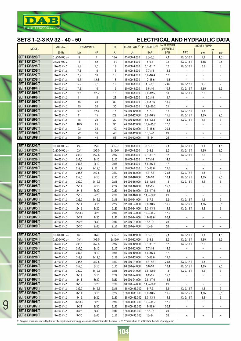
104
9
®
(1) Range of pressure achieved by the set: the requirement working pressure must be indicated in the order. – (2) * These tables do not include the data of jockey pump.
ELECTRICAL AND HYDRAULIC DATA
SET 1 KV 32/3 T 3x230-400 V~ 3 4 12-7 15.000-4.000 3.6÷6,8 7,1 KV 3/10 T 1,1 1,5
SET 1 KV 32/4 T 3x230-400 V~ 4 5,5 16-9 15.000-4.000 5÷9,3 9,6 KV 3/15 T 1,85 2,5
SET 1 KV 32/5 T 3x400 V~ ∆ 5,5 7,5 12 15.000-4.000 6,1÷11,7 12 KV 3/18 T 2.2 3
SET 1 KV 32/6 T 3x400 V~ ∆ 7,5 10 15 15.000-4.000 7,7÷14 14,5 – – –
SET 1 KV 32/7 T 3x400 V~ ∆ 7,5 10 15 15.000-4.000 8,6÷16,4 17 – – –
SET 1 KV 32/8 T 3x400 V~ ∆ 9,2 12,5 18 15.000-4.000 10÷18,6 19,6 – – –
SET 1 KV 40/3 T 3x400 V~ ∆ 5,5 7,5 12 30.000-8.000 4,3÷7,3 7,85 KV 3/12 T 1,5 2
SET 1 KV 40/4 T 3x400 V~ ∆ 7,5 10 15 30.000-8.000 5,6÷10 10,4 KV 3/15 T 1,85 2,5
SET 1 KV 40/5 T 3x400 V~ ∆ 9,2 12,5 18 30.000-8.000 6,8÷12,5 13 KV 3/18 T 2.2 3
SET 1 KV 40/6 T 3x400 V~ ∆ 11 15 22 30.000-8.000 8,2÷15 15,7 – – –
SET 1 KV 40/7 T 3x400 V~ ∆ 15 20 30 30.000-8.000 9,8÷17,6 18,5 – – –
SET 1 KV 40/8 T 3x400 V~ ∆ 15 20 30 30.000-8.000 11,9÷20,2 21 – – –
SET 1 KV 50/3 T 3x400 V~ ∆ 9,2 12,5 18 46.000-12.000 5÷7,9 8,6 KV 3/12 T 1,5 2
SET 1 KV 50/4 T 3x400 V~ ∆ 11 15 22 46.000-12.000 6,8÷10,5 11,5 KV 3/15 T 1,85 2,5
SET 1 KV 50/5 T 3x400 V~ ∆ 15 20 30 46.000-12.000 8,5÷13,3 14,8 KV 3/18 T 2.2 3
SET 1 KV 50/6 T 3x400 V~ ∆ 18,5 25 36 46.000-12.000 10,2÷15,7 17,6 – – –
SET 1 KV 50/7 T 3x400 V~ ∆ 22 30 40 46.000-12.000 12÷18,6 20,4 – – –
SET 1 KV 50/8 T 3x400 V~ ∆ 22 30 40 46.000-12.000 13,8÷21 23 – – –
SET 1 KV 50/9 T 3x400 V~ ∆ 30 40 56 46.000-12.000 16÷24 26 – – –
VOLTAGE P2 NOMINAL In FLOW RATE (2) PRESSURE (1)
50 Hz kW HP A L/h BAR BAR
MAX PRESSUREOBTAINABLE
JOCKEY PUMP
TIPOP2
kW HP
SET 2 KV 32/3 T 3x230-400 V~ 2x3 2x4 2x12-7 30.000-8.000 3.6÷6,8 7,1 KV 3/10 T 1,1 1,5
SET 2 KV 32/4 T 3x230-400 V~ 2x4 2x5,5 2x16-9 30.000-8.000 5÷9,3 9,6 KV 3/15 T 1,85 2,5
SET 2 KV 32/5 T 3x400 V~ ∆ 2x5,5 2x7,5 2x12 30.000-8.000 6,1÷11,7 12 KV 3/18 T 2.2 3
SET 2 KV 32/6 T 3x400 V~ ∆ 2x7,5 2x10 2x15 30.000-8.000 7,7÷14 14,5 – – –
SET 2 KV 32/7 T 3x400 V~ ∆ 2x7,5 2x10 2x15 30.000-8.000 8,6÷16,4 17 – – –
SET 2 KV 32/8 T 3x400 V~ ∆ 2x9,2 2x12,5 2x18 30.000-8.000 10÷18,6 19,6 – – –
SET 2 KV 40/3 T 3x400 V~ ∆ 2x5,5 2x7,5 2x12 60.000-16.000 4,3÷7,3 7,85 KV 3/12 T 1,5 2
SET 2 KV 40/4 T 3x400 V~ ∆ 2x7,5 2x10 2x15 60.000-16.000 5,6÷10 10,4 KV 3/15 T 1,85 2,5
SET 2 KV 40/5 T 3x400 V~ ∆ 2x9,2 2x12,5 2x18 60.000-16.000 6,8÷12,5 13 KV 3/18 T 2.2 3
SET 2 KV 40/6 T 3x400 V~ ∆ 2x11 2x15 2x22 60.000-16.000 8,2÷15 15,7 – – –
SET 2 KV 40/7 T 3x400 V~ ∆ 2x15 2x20 2x30 60.000-16.000 9,8÷17,6 18,5 – – –
SET 2 KV 40/8 T 3x400 V~ ∆ 2x15 2x20 2x30 60.000-16.000 11,9÷20,2 21 – – –
SET 2 KV 50/3 T 3x400 V~ ∆ 2x9,2 2x12,5 2x18 92.000-24.000 5÷7,9 8,6 KV 3/12 T 1,5 2
SET 2 KV 50/4 T 3x400 V~ ∆ 2x11 2x15 2x22 92.000-24.000 6,8÷10,5 11,5 KV 3/15 T 1,85 2,5
SET 2 KV 50/5 T 3x400 V~ ∆ 2x15 2x20 2x30 92.000-24.000 8,5÷13,3 14,8 KV 3/18 T 2.2 3
SET 2 KV 50/6 T 3x400 V~ ∆ 2x18,5 2x25 2x36 92.000-24.000 10,2÷15,7 17,6 – – –
SET 2 KV 50/7 T 3x400 V~ ∆ 2x22 2x30 2x40 92.000-24.000 12÷18,6 20,4 – – –
SET 2 KV 50/8 T 3x400 V~ ∆ 2x22 2x30 2x40 92.000-24.000 13,8÷21 23 – – –
SET 2 KV 50/9 T 3x400 V~ ∆ 2x30 2x40 2x56 92.000-24.000 16÷24 26 – – –
SET 3 KV 32/3 T 3x230-400 V~ 3x3 3x4 3x12-7 45.000-12.000 3.6÷6,8 7,1 KV 3/10 T 1,1 1,5
SET 3 KV 32/4 T 3x230-400 V~ 3x4 3x5,5 3x16-9 45.000-12.000 5÷9,3 9,6 KV 3/15 T 1,85 2,5
SET 3 KV 32/5 T 3x400 V~ ∆ 3x5,5 3x7,5 3x12 45.000-12.000 6,1÷11,7 12 KV 3/18 T 2.2 3
SET 3 KV 32/6 T 3x400 V~ ∆ 3x7,5 3x10 3x15 45.000-12.000 7,7÷14 14,5 – – –
SET 3 KV 32/7 T 3x400 V~ ∆ 3x7,5 3x10 3x15 45.000-12.000 8,6÷16,4 17 – – –
SET 3 KV 32/8 T 3x400 V~ ∆ 3x9,2 3x12,5 3x18 45.000-12.000 10÷18,6 19,6 – – –
SET 3 KV 40/3 T 3x400 V~ ∆ 3x5,5 3x7,5 3x12 90.000-24.000 4,3÷7,3 7,85 KV 3/12 T 1,5 2
SET 3 KV 40/4 T 3x400 V~ ∆ 3x7,5 3x10 3x15 90.000-24.000 5,6÷10 10,4 KV 3/15 T 1,85 2,5
SET 3 KV 40/5 T 3x400 V~ ∆ 3x9,2 3x12,5 3x18 90.000-24.000 6,8÷12,5 13 KV 3/18 T 2.2 3
SET 3 KV 40/6 T 3x400 V~ ∆ 3x11 3x15 3x22 90.000-24.000 8,2÷15 15,7 – – –
SET 3 KV 40/7 T 3x400 V~ ∆ 3x15 3x20 3x30 90.000-24.000 9,8÷17,6 18,5 – – –
SET 3 KV 40/8 T 3x400 V~ ∆ 3x15 3x20 3x30 90.000-24.000 11,9÷20,2 21 – – –
SET 3 KV 50/3 T 3x400 V~ ∆ 3x9,2 3x12,5 3x18 138.000-36.000 5÷7,9 8,6 KV 3/12 T 1,5 2
SET 3 KV 50/4 T 3x400 V~ ∆ 3x11 3x15 3x22 138.000-36.000 6,8÷10,5 11,5 KV 3/15 T 1,85 2,5
SET 3 KV 50/5 T 3x400 V~ ∆ 3x15 3x20 3x30 138.000-36.000 8,5÷13,3 14,8 KV 3/18 T 2.2 3
SET 3 KV 50/6 T 3x400 V~ ∆ 3x18,5 3x25 3x36 138.000-36.000 10,2÷15,7 17,6 – – –
SET 3 KV 50/7 T 3x400 V~ ∆ 3x22 3x30 3x40 138.000-36.000 12÷18,6 20,4 – – –
SET 3 KV 50/8 T 3x400 V~ ∆ 3x22 3x30 3x40 138.000-36.000 13,8÷21 23 – – –
SET 3 KV 50/9 T 3x400 V~ ∆ 3x30 3x40 3x56 138.000-36.000 16÷24 26 – – –
MODEL
SETS 1-2-3 KV 32 - 40 - 50
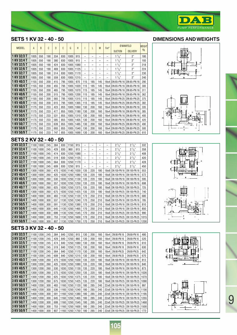
105
9
®
SETS 1 KV 32 - 40 - 50 DIMENSIONS AND WEIGHTS
1 KV 32/3 T 1005 550 190 334 830 1005 915 – – – – 1 1/2” 2” 180
1 KV 32/4 T 1005 550 190 380 830 1005 915 – – – – 1 1/2” 2” 193
1 KV 32/5 T 1005 550 190 424 830 1005 1080 – – – – 1 1/2” 2” 218
1 KV 32/6 T 1005 550 190 469 830 1005 1125 – – – – 1 1/2” 2” 224
1 KV 32/7 T 1005 550 190 514 830 1005 1170 – – – – 1 1/2” 2” 230
1 KV 32/8 T 1005 550 190 559 830 1005 1215 – – – – 1 1/2” 2” 240
1 KV 40/3 T 1155 550 200 415 795 1005 970 115 185 145 18x4 DN 65-PN 16 DN 65-PN 16 290
1 KV 40/4 T 1155 550 200 455 795 1005 1020 115 185 145 18x4 DN 65-PN 16 DN 65-PN 16 300
1 KV 40/5 T 1155 550 200 465 795 1005 1070 115 185 145 18x4 DN 65-PN 16 DN 65-PN 16 311
1 KV 40/6 T 1155 550 200 515 795 1005 1200 115 185 145 18x4 DN 65-PN 16 DN 65-PN 16 362
1 KV 40/7 T 1155 550 200 565 795 1005 1315 115 185 145 18x4 DN 65-PN 25 DN 65-PN 25 375
1 KV 40/8 T 1155 550 200 615 795 1005 1365 115 185 145 18x4 DN 65-PN 25 DN 65-PN 25 382
1 KV 50/3 T 1175 550 233 423 855 1005 1060 130 200 160 18x4 DN 80-PN 16 DN 80-PN 16 335
1 KV 50/4 T 1175 550 233 477 855 1005 1180 130 200 160 18x4 DN 80-PN 16 DN 80-PN 16 385
1 KV 50/5 T 1175 550 233 531 855 1005 1310 130 200 160 18x4 DN 80-PN 16 DN 80-PN 16 400
1 KV 50/6 T 1175 550 233 585 855 1005 1405 130 200 160 18x4 DN 80-PN 16 DN 80-PN 16 420
1 KV 50/7 T 1175 550 233 639 855 1005 1485 130 200 160 18x4 DN 80-PN 25 DN 80-PN 25 490
1 KV 50/8 T 1175 550 233 693 855 1005 1540 130 200 160 18x4 DN 80-PN 25 DN 80-PN 25 500
1 KV 50/9 T 1175 550 233 747 855 1005 1690 130 200 160 18x4 DN 80-PN 25 DN 80-PN 25 610
A B C D E G H I L M Fxn°WEIGHT
Kg.Ø MANIFOLD
SUCTION DELIVERY
2 KV 32/3 T 1100 1000 245 384 830 1150 915 – – – – 2 1/2” 2 1/2” 332
2 KV 32/4 T 1100 1000 245 429 830 960 915 – – – – 2 1/2” 2 1/2” 358
2 KV 32/5 T 1100 1000 245 474 830 1250 1080 – – – – 2 1/2” 2 1/2” 408
2 KV 32/6 T 1100 1000 245 519 830 1250 1125 – – – – 2 1/2” 2 1/2” 420
2 KV 32/7 T 1100 1000 245 564 830 1250 1170 – – – – 2 1/2” 2 1/2” 428
2 KV 32/8 T 1100 1000 245 609 830 1250 915 – – – – 2 1/2” 2 1/2” 450
2 KV 40/3 T 1300 1000 260 470 1030 1140 1030 135 220 180 18x8 DN 100-PN 16 DN 100-PN 16 553
2 KV 40/4 T 1300 1000 260 425 1030 1250 1080 135 220 180 18x8 DN 100-PN 16 DN 100-PN 16 572
2 KV 40/5 T 1300 1000 260 530 1030 1250 1130 135 220 180 18x8 DN 100-PN 16 DN 100-PN 16 595
2 KV 40/6 T 1300 1000 260 557 1030 1250 1250 135 220 180 18x8 DN 100-PN 16 DN 100-PN 16 698
2 KV 40/7 T 1300 1000 260 625 1030 1250 1375 135 220 180 18x8 DN 100-PN 25 DN 100-PN 25 725
2 KV 40/8 T 1300 1000 260 675 1030 1250 1425 135 220 180 18x8 DN 100-PN 25 DN 100-PN 25 740
2 KV 50/3 T 1400 1000 300 483 1130 1250 1120 170 250 210 18x8 DN 125-PN 16 DN 125-PN 16 680
2 KV 50/4 T 1400 1000 300 537 1130 1250 1240 170 250 210 18x8 DN 125-PN 16 DN 125-PN 16 785
2 KV 50/5 T 1400 1000 300 591 1130 1250 1380 170 250 210 18x8 DN 125-PN 16 DN 125-PN 16 810
2 KV 50/6 T 1400 1000 300 645 1130 1250 1465 170 250 210 18x8 DN 125-PN 16 DN 125-PN 16 850
2 KV 50/7 T 1400 1000 300 699 1130 1250 1545 170 250 210 18x8 DN 125-PN 25 DN 125-PN 25 990
2 KV 50/8 T 1400 1000 300 753 1130 1250 1600 170 250 210 18x8 DN 125-PN 25 DN 125-PN 25 1015
2 KV 50/9 T 1400 1000 300 807 1130 1250 1750 170 250 210 18x8 DN 125-PN 25 DN 125-PN 25 1200
3 KV 32/3 T 1100 1200 245 384 840 1250 915 130 200 160 18x4 DN 80-PN 16 DN 80-PN 16 480
3 KV 32/4 T 1100 1200 245 429 840 1250 960 130 200 160 18x4 DN 80-PN 16 DN 80-PN 16 520
3 KV 32/5 T 1100 1200 245 474 840 1250 1080 130 200 160 18x4 DN 80-PN 16 DN 80-PN 16 610
3 KV 32/6 T 1100 1200 245 519 840 1250 1125 130 200 160 18x4 DN 80-PN 16 DN 80-PN 16 630
3 KV 32/7 T 1100 1200 245 564 840 1250 1170 130 200 160 18x4 DN 80-PN 25 DN 80-PN 25 642
3 KV 32/8 T 1100 1200 245 609 840 1250 1215 130 200 160 18x4 DN 80-PN 25 DN 80-PN 25 670
3 KV 40/3 T 1300 1200 260 470 1030 1250 1030 135 220 180 18x8 DN 100-PN 16 DN 100-PN 16 813
3 KV 40/4 T 1300 1200 260 425 1030 1250 1080 135 220 180 18x8 DN 100-PN 16 DN 100-PN 16 840
3 KV 40/5 T 1300 1200 260 530 1030 1250 1130 135 220 180 18x8 DN 100-PN 16 DN 100-PN 16 873
3 KV 40/6 T 1300 1200 260 575 1030 1250 1250 135 220 180 18x8 DN 100-PN 16 DN 100-PN 16 1026
3 KV 40/7 T 1300 1200 260 625 1030 1250 1375 135 220 180 18x8 DN 100-PN 25 DN 100-PN 25 1070
3 KV 40/8 T 1300 1200 260 675 1030 1250 1425 135 220 180 18x8 DN 100-PN 25 DN 100-PN 25 1090
3 KV 50/3 T 1400 1200 300 483 1160 1250 1120 180 285 240 22x8 DN 150-PN 16 DN 150-PN 16 997
3 KV 50/4 T 1400 1200 300 536 1160 1250 1240 180 285 240 22x8 DN 150-PN 16 DN 150-PN 16 1156
3 KV 50/5 T 1400 1200 300 591 1160 1250 1380 180 285 240 22x8 DN 150-PN 16 DN 150-PN 16 1195
3 KV 50/6 T 1400 1200 300 645 1160 1250 1465 180 285 240 22x8 DN 150-PN 16 DN 150-PN 16 1255
3 KV 50/7 T 1400 1200 300 699 1160 1250 1545 180 285 240 22x8 DN 150-PN 25 DN 150-PN 25 1468
3 KV 50/8 T 1400 1000 300 753 1160 1250 1600 180 285 240 22x8 DN 150-PN 25 DN 150-PN 25 1500
3 KV 50/9 T 1400 1000 300 807 1160 1250 1750 180 285 240 22x8 DN 150-PN 25 DN 150-PN 25 1770
SETS 2 KV 32 - 40 - 50
SETS 3 KV 32 - 40 - 50
MODEL
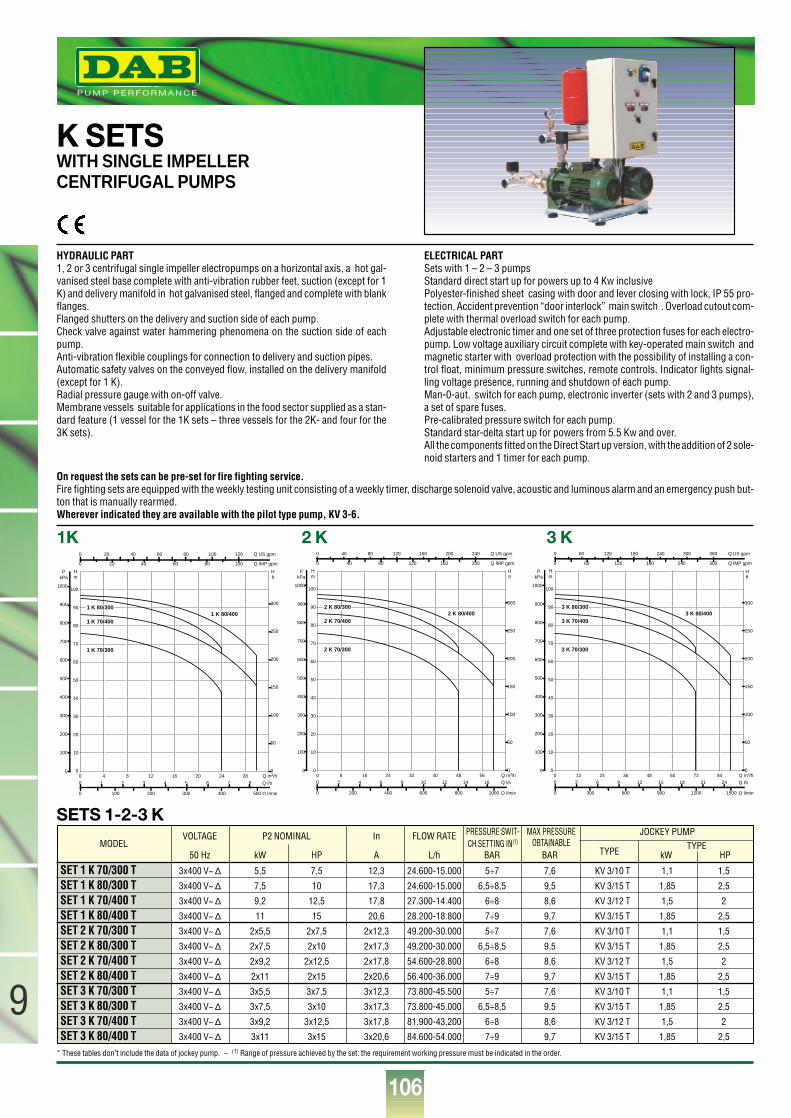
106
9
®
SETS 1-2-3 K
K SETSWITH SINGLE IMPELLERCENTRIFUGAL PUMPS
HYDRAULIC PART1, 2 or 3 centrifugal single impeller electropumps on a horizontal axis, a hot gal-vanised steel base complete with anti-vibration rubber feet, suction (except for 1K) and delivery manifold in hot galvanised steel, flanged and complete with blankflanges.Flanged shutters on the delivery and suction side of each pump.Check valve against water hammering phenomena on the suction side of eachpump.Anti-vibration flexible couplings for connection to delivery and suction pipes.Automatic safety valves on the conveyed flow, installed on the delivery manifold(except for 1 K).Radial pressure gauge with on-off valve.Membrane vessels suitable for applications in the food sector supplied as a stan-dard feature (1 vessel for the 1K sets – three vessels for the 2K- and four for the3K sets).
ELECTRICAL PART Sets with 1 – 2 – 3 pumpsStandard direct start up for powers up to 4 Kw inclusivePolyester-finished sheet casing with door and lever closing with lock, IP 55 pro-tection. Accident prevention “door interlock” main switch . Overload cutout com-plete with thermal overload switch for each pump.Adjustable electronic timer and one set of three protection fuses for each electro-pump. Low voltage auxiliary circuit complete with key-operated main switch andmagnetic starter with overload protection with the possibility of installing a con-trol float, minimum pressure switches, remote controls. Indicator lights signal-ling voltage presence, running and shutdown of each pump.Man-0-aut. switch for each pump, electronic inverter (sets with 2 and 3 pumps),a set of spare fuses.Pre-calibrated pressure switch for each pump.Standard star-delta start up for powers from 5.5 Kw and over.All the components fitted on the Direct Start up version, with the addition of 2 sole-noid starters and 1 timer for each pump.
SET 1 K 70/300 T 3x400 V~ ∆ 5,5 7,5 12,3 24.600-15.000 5÷7 7,6 KV 3/10 T 1,1 1,5
SET 1 K 80/300 T 3x400 V~ ∆ 7,5 10 17,3 24.600-15.000 6,5÷8,5 9,5 KV 3/15 T 1,85 2,5
SET 1 K 70/400 T 3x400 V~ ∆ 9,2 12,5 17,8 27.300-14.400 6÷8 8,6 KV 3/12 T 1,5 2
SET 1 K 80/400 T 3x400 V~ ∆ 11 15 20,6 28.200-18.800 7÷9 9,7 KV 3/15 T 1,85 2,5
SET 2 K 70/300 T 3x400 V~ ∆ 2x5,5 2x7,5 2x12,3 49.200-30.000 5÷7 7,6 KV 3/10 T 1,1 1,5
SET 2 K 80/300 T 3x400 V~ ∆ 2x7,5 2x10 2x17,3 49.200-30.000 6,5÷8,5 9,5 KV 3/15 T 1,85 2,5
SET 2 K 70/400 T 3x400 V~ ∆ 2x9,2 2x12,5 2x17,8 54.600-28.800 6÷8 8,6 KV 3/12 T 1,5 2
SET 2 K 80/400 T 3x400 V~ ∆ 2x11 2x15 2x20,6 56.400-36.000 7÷9 9,7 KV 3/15 T 1,85 2,5
SET 3 K 70/300 T 3x400 V~ ∆ 3x5,5 3x7,5 3x12,3 73.800-45.500 5÷7 7,6 KV 3/10 T 1,1 1,5
SET 3 K 80/300 T 3x400 V~ ∆ 3x7,5 3x10 3x17,3 73.800-45.000 6,5÷8,5 9,5 KV 3/15 T 1,85 2,5
SET 3 K 70/400 T 3x400 V~ ∆ 3x9,2 3x12,5 3x17,8 81.900-43.200 6÷8 8,6 KV 3/12 T 1,5 2
SET 3 K 80/400 T 3x400 V~ ∆ 3x11 3x15 3x20,6 84.600-54.000 7÷9 9,7 KV 3/15 T 1,85 2,5
VOLTAGE P2 NOMINAL In FLOW RATE
50 Hz kW HP A L/h BAR BAR
MAX PRESSUREOBTAINABLE
JOCKEY PUMPPRESSURE SWIT-CH SETTING IN(1)
TYPE TYPEkW HP
MODEL
On request the sets can be pre-set for fire fighting service.Fire fighting sets are equipped with the weekly testing unit consisting of a weekly timer, discharge solenoid valve, acoustic and luminous alarm and an emergency push but-ton that is manually rearmed.Wherever indicated they are available with the pilot type pump, KV 3-6.
Q m3/h0
10
20
30
40
50
60
70
80
90
100
Hm
0
100
200
300
400
500
600
700
800
900
1000
PkPa
0 100 200 300 400 500 Q l/min
0 1 2 3 4 5 6 7 80 4 8 12 16 20 24 28
Q l/s
0
50
100
150
200
250
300
H ft
0 20 40 60 80 100 120 Q US gpm
0 20 40 60 80 100 Q IMP gpm
1 K 80/4001 K 70/400
1 K 80/300
1 K 70/300
1K
Q m3/h0
10
20
30
40
50
60
70
80
90
100
Hm
0
100
200
300
400
500
600
700
800
900
1000
PkPa
0 200 400 600 800 1000 Q l/min
0 2 4 6 8 10 12 14 160 8 16 24 32 40 48 56
Q l/s
0
50
100
150
200
250
300
H ft
0 40 80 120 160 200 240 Q US gpm
0 40 80 120 160 200 Q IMP gpm
2 K 80/4002 K 70/400
2 K 80/300
2 K 70/300
2 K
Q m3/h0
10
20
30
40
50
60
70
80
90
100
Hm
0
100
200
300
400
500
600
700
800
900
1000
PkPa
0 300 600 900 1200 1500 Q l/min
0 3 6 9 12 15 18 21 240 12 24 36 48 60 72 84
Q l/s
0
50
100
150
200
250
300
H ft
0 60 120 180 240 300 360 Q US gpm
0 60 120 180 240 300 Q IMP gpm
3 K 80/4003 K 70/400
3 K 80/300
3 K 70/300
3 K
* These tables don’t include the data of jockey pump. – (1) Range of pressure achieved by the set: the requirement working pressure must be indicated in the order.
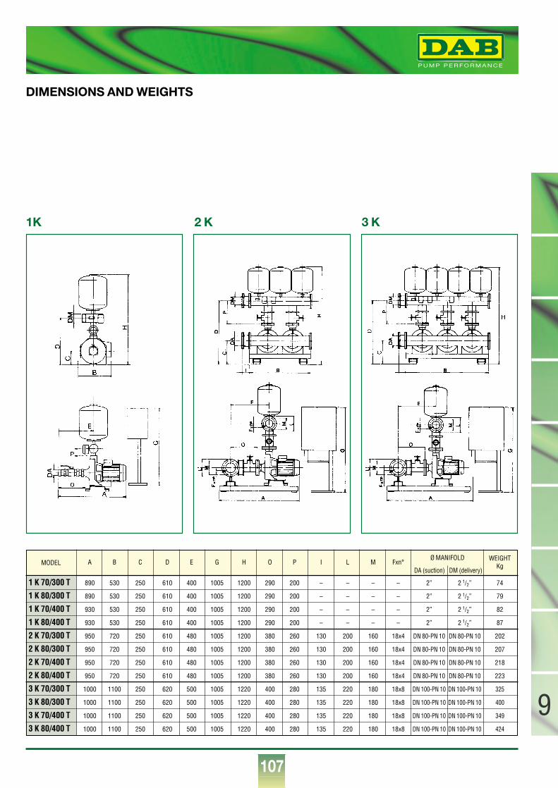
107
9
®
1 K 70/300 T 890 530 250 610 400 1005 1200 290 200 – – – – 2” 2 1/2” 74
1 K 80/300 T 890 530 250 610 400 1005 1200 290 200 – – – – 2” 2 1/2” 79
1 K 70/400 T 930 530 250 610 400 1005 1200 290 200 – – – – 2” 2 1/2” 82
1 K 80/400 T 930 530 250 610 400 1005 1200 290 200 – – – – 2” 2 1/2” 87
2 K 70/300 T 950 720 250 610 480 1005 1200 380 260 130 200 160 18x4 DN 80-PN 10 DN 80-PN 10 202
2 K 80/300 T 950 720 250 610 480 1005 1200 380 260 130 200 160 18x4 DN 80-PN 10 DN 80-PN 10 207
2 K 70/400 T 950 720 250 610 480 1005 1200 380 260 130 200 160 18x4 DN 80-PN 10 DN 80-PN 10 218
2 K 80/400 T 950 720 250 610 480 1005 1200 380 260 130 200 160 18x4 DN 80-PN 10 DN 80-PN 10 223
3 K 70/300 T 1000 1100 250 620 500 1005 1220 400 280 135 220 180 18x8 DN 100-PN 10 DN 100-PN 10 325
3 K 80/300 T 1000 1100 250 620 500 1005 1220 400 280 135 220 180 18x8 DN 100-PN 10 DN 100-PN 10 400
3 K 70/400 T 1000 1100 250 620 500 1005 1220 400 280 135 220 180 18x8 DN 100-PN 10 DN 100-PN 10 349
3 K 80/400 T 1000 1100 250 620 500 1005 1220 400 280 135 220 180 18x8 DN 100-PN 10 DN 100-PN 10 424
A B C D E G H O P I L M Fxn° WEIGHT Kg
Ø MANIFOLD
DA (suction) DM (delivery)
DIMENSIONS AND WEIGHTS
MODEL
1K 2 K 3 K
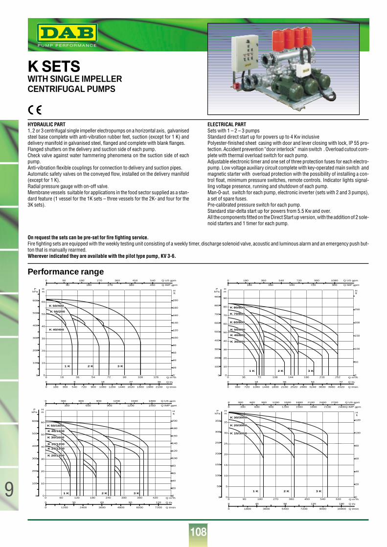
108
9
®
Performance range
K SETSWITH SINGLE IMPELLERCENTRIFUGAL PUMPS
HYDRAULIC PART1, 2 or 3 centrifugal single impeller electropumps on a horizontal axis, galvanisedsteel base complete with anti-vibration rubber feet, suction (except for 1 K) anddelivery manifold in galvanised steel, flanged and complete with blank flanges.Flanged shutters on the delivery and suction side of each pump.Check valve against water hammering phenomena on the suction side of eachpump.Anti-vibration flexible couplings for connection to delivery and suction pipes.Automatic safety valves on the conveyed flow, installed on the delivery manifold(except for 1 K).Radial pressure gauge with on-off valve.Membrane vessels suitable for applications in the food sector supplied as a stan-dard feature (1 vessel for the 1K sets – three vessels for the 2K- and four for the3K sets).
ELECTRICAL PART Sets with 1 – 2 – 3 pumpsStandard direct start up for powers up to 4 Kw inclusivePolyester-finished sheet casing with door and lever closing with lock, IP 55 pro-tection. Accident prevention “door interlock” main switch . Overload cutout com-plete with thermal overload switch for each pump.Adjustable electronic timer and one set of three protection fuses for each electro-pump. Low voltage auxiliary circuit complete with key-operated main switch andmagnetic starter with overload protection with the possibility of installing a con-trol float, minimum pressure switches, remote controls. Indicator lights signal-ling voltage presence, running and shutdown of each pump.Man-0-aut. switch for each pump, electronic inverter (sets with 2 and 3 pumps),a set of spare fuses.Pre-calibrated pressure switch for each pump.Standard star-delta start up for powers from 5.5 Kw and over.All the components fitted on the Direct Start up version, with the addition of 2 sole-noid starters and 1 timer for each pump.
On request the sets can be pre-set for fire fighting service.Fire fighting sets are equipped with the weekly testing unit consisting of a weekly timer, discharge solenoid valve, acoustic and luminous alarm and an emergency push but-ton that is manually rearmed.Wherever indicated they are available with the pilot type pump, KV 3-6.
0 Q m3/h18 36 54 72 90 108 1260
10
20
30
40
50
60
Hm
0
100
200
300
400
500
600
PkPa
0 180 360 540 720 900 1080 1260 1440 1620 1800 1980 2160 Q l/min
0 9 18 27 36 Q l/s
0
20
40
60
80
100
120
140
160
180
200
H ft
0 90 180 270 360 450 540 Q US gpm
0 90 180 270 360 450 Q IMP gpm
K 40/400
1 K 2 K 3 K
K 55/200
K 50/400
0 Q m3/h60 120 180 240 300 360 4200
10
20
30
40
50
60
Hm
0
100
200
300
400
500
600
PkPa
0 1200 2400 3600 4800 6000 7200 Q l/min
0 30 60 90 120 Q l/s
0
20
40
60
80
100
120
140
160
180
200
H ft
0 300 600 900 1200 1500 1800 Q US gpm
0 300 600 900 1200 1500 Q IMP gpm
K 50/1600
K 30/1600
K 35/1200
K 20/1200
1 K 2 K 3 K
K 40/1600
K 25/1200
0 Q m3/h36 72 108 144 180 216 2520
10
20
30
40
50
60
70
80
90
Hm
0
100
200
300
400
500
600
700
800
900
PkPa
0 360 720 1080 1440 1800 2160 2520 2880 3240 3600 3960 4320 Q l/min
0 18 36 54 72 Q l/s
0
50
100
150
200
250
H ft
0 180 360 540 720 900 1080 Q US gpm
0 180 360 540 720 900 Q IMP gpm
K 80/800
K 70/800
K 60/800
K 50/800
K 40/800
K 30/800
1 K 2 K 3 K
0 Q m3/h90 180 270 360 450 540 6300
5
10
15
20
25
30
35
Hm
0
50
100
150
200
250
300
350
PkPa
0 1800 3600 5400 7200 9000 10800 Q l/min
0 45 90 135 180 Q l/s
0
20
40
60
80
100
120
H ft
0 300 600 900 1200 1500 1800 2100 2400 2700 Q US gpm
0 300 600 900 1200 1500 1800 2100 2400 Q IMP gpm
K 30/3000
K 20/3000
K 15/3000
1 K 2 K 3 K

109
9
®
SET 1 K 55/200 T 3x230-400 V~ ∆ 4 5,5 16,3-9,4 17.000-8.000 4,3÷5,1 5,2 KV 6/7 T 1,1 1,5
SET 1 K 40/400 T 3x400 V~ ∆ 5,5 7,5 11,5 29.000-17.000 2,7÷4,6 4,9 KV 6/7 T 1,1 1,5
SET 1 K 50/400 T 3x400 V~ ∆ 7,5 10 15 33.500-20.000 3,6÷5,8 6,2 KV 6/7 T 1,1 1,5
SET 1 K 30/800 T 3x400 V~ ∆ 7,5 10 14 60.000-27.500 2,2÷3,9 4,4 KV 6/7 T 1,1 1,5
SET 1 K 40/800 T 3x400 V~ ∆ 9,2 12,5 18 66.000-36.000 2,7÷4,7 5 KV 6/7 T 1,1 1,5
SET 1 K 50/800 T 3x400 V~ ∆ 11 15 20,5 72.000-36.000 3,2÷5,5 5,75 KV 3/10 T 1,1 1,5
SET 1 K 60/800 T 3x400 V~ ∆ 15 20 29 72.000-36.000 3,8÷6,7 6,9 KV 3/10 T 1,1 1,5
SET 1 K 70/800 T 3x400 V~ ∆ 18,5 25 36 75.000-36.000 4,5÷7,2 7,6 KV 3/10 T 1,1 1,5
SET 1 K 80/800 T 3x400 V~ ∆ 22 30 40 81.000-36.000 4,9÷7,9 8,3 KV 3/12 T 1,5 2
SET 1 K 20/1200 T 3x400 V~ ∆ 7,5 10 15,4 93.000-48.000 1,2÷2,7 3,2 KV 6/7 T 1,1 1,5
SET 1 K 25/1200 T 3x400 V~ ∆ 9,2 12,5 18 96.000-48.000 1,7÷3,3 3,7 KV 6/7 T 1,1 1,5
SET 1 K 35/1200 T 3x400 V~ ∆ 11 15 19,3 96.000-60.000 2,5÷3,8 4,2 KV 6/7 T 1,1 1,5
SET 1 K 30/1600 T 3x400 V~ ∆ 15 20 31 120.000-72.000 3,1÷4,5 5 KV 6/7 T 1,1 1,5
SET 1 K 40/1600 T 3x400 V~ ∆ 18,5 25 37 120.000-72.000 3,9÷5,1 5,4 KV 6/7 T 1,1 1,5
SET 1 K 50/1600 T 3x400 V~ ∆ 22 30 42 120.000-72.000 4,6÷5,7 5,8 KV 3/10 T 1,1 1,5
SET 1 K 15/3000 T 3x400 V~ ∆ 15 20 30 192.000-75.000 1,8÷3 3 KV 6/7 T 1,1 1,5
SET 1 K 20/3000 T 3x400 V~ ∆ 18,5 25 32,1 192.000-90.000 2,5÷3,6 3,6 KV 6/7 T 1,1 1,5
SET 1 K 30/3000 T 3x400 V~ ∆ 22 30 40 192.000-90.000 2,7÷4 4 KV 6/7 T 1,1 1,5
VOLTAGE P2 NOMINAL In FLOW RATE (2) PRESSURE (1)
50 Hz kW HP A l/h BAR BAR
MAX PRESSUREOBTAINABLE
JOCKEY PUMP
TIPO P2kW HP
SET 2 K 55/200 T 3x230-400 V~ ∆ 2x4 2x5,5 2x16,3-9,4 34.000-16.000 4,3÷5,1 5,2 KV 6/7 T 1,1 1,5
SET 2 K 40/400 T 3x400 V~ ∆ 2x5,5 2x7,5 2x11,5 58.000-34.000 2,7÷4,6 4,9 KV 6/7 T 1,1 1,5
SET 2 K 50/400 T 3x400 V~ ∆ 2x7,5 2x10 2x15 67.000-40.000 3,6÷5,8 6,2 KV 6/7 T 1,1 1,5
SET 2 K 30/800 T 3x400 V~ ∆ 2x7,5 2x10 2x14 120.000-55.000 2,2÷3,9 4,4 KV 6/7 T 1,1 1,5
SET 2 K 40/800 T 3x400 V~ ∆ 2x9,2 2x12,5 2x18 132.000-72.000 2,7÷4,7 5 KV 6/7 T 1,1 1,5
SET 2 K 50/800 T 3x400 V~ ∆ 2x11 2x15 2x20,5 144.000-72.000 3,2÷5,5 5,75 KV 3/10 T 1,1 1,5
SET 2 K 60/800 T 3x400 V~ ∆ 2x15 2x20 2x29 144.000-72.000 3,8÷6,7 6,9 KV 3/10 T 1,1 1,5
SET 2 K 70/800 T 3x400 V~ ∆ 2x18,5 2x25 2x36 150.000-72.000 4,5÷7,2 7,6 KV 3/10 T 1,1 1,5
SET 2 K 80/800 T 3x400 V~ ∆ 2x22 2x30 2x40 162.000-72.000 4,9÷7,9 8,3 KV 3/12 T 1,5 2
SET 2 K 20/1200 T 3x400 V~ ∆ 2x7,5 2x10 2x15,4 186.000-96.000 1,2÷2,7 3,2 KV 6/7 T 1,1 1,5
SET 2 K 25/1200 T 3x400 V~ ∆ 2x9,2 2x12,5 2x18 192.000-96.000 1,7÷3,3 3,7 KV 6/7 T 1,1 1,5
SET 2 K 35/1200 T 3x400 V~ ∆ 2x11 2x15 2x19,3 192.000-120.000 2,5÷3,8 4,2 KV 6/7 T 1,1 1,5
SET 2 K 30/1600 T 3x400 V~ ∆ 2x15 2x20 2x31 240.000-144.000 3,1÷4,5 5 KV 6/7 T 1,1 1,5
SET 2 K 40/1600 T 3x400 V~ ∆ 2x18,5 2x25 2x37 240.000-144.000 3,9÷5,1 5,4 KV 6/7 T 1,1 1,5
SET 2 K 50/1600 T 3x400 V~ ∆ 2x22 2x30 2x42 240.000-144.000 4,6÷5,7 5,8 KV 3/10 T 1,1 1,5
SET 2 K 15/3000 T 3x400 V~ ∆ 2x15 2x20 2x30 384.000-150.000 1,8÷3 3 KV 6/7 T 1,1 1,5
SET 2 K 20/3000 T 3x400 V~ ∆ 2x18,5 2x25 2x32,1 384.000-150.000 2,5÷3,6 3,6 KV 6/7 T 1,1 1,5
SET 2 K 30/3000 T 3x400 V~ ∆ 2x22 2x30 2x40 384.000-150.000 2,7÷4 4 KV 6/7 T 1,1 1,5
SET 3 K 55/200 T 3x230-400 V~ ∆ 3x4 3x5,5 3x16,3-9,4 51.000-24.000 4,3÷5,1 5,2 KV 6/7 T 1,1 1,5
SET 3 K 40/400 T 3x400 V~ ∆ 3x5,5 3x7,5 3x11,5 87.000-51.000 2,7÷4,6 4,9 KV 6/7 T 1,1 1,5
SET 3 K 50/400 T 3x400 V~ ∆ 3x7,5 3x10 3x15 100.500-60.000 3,6÷5,8 6,2 KV 6/7 T 1,1 1,5
SET 3 K 30/800 T 3x400 V~ ∆ 3x7,5 3x10 3x14 180.000-82.500 2,2÷3,9 4,4 KV 6/7 T 1,1 1,5
SET 3 K 40/800 T 3x400 V~ ∆ 3x9,2 3x12,5 3x18 198.000-108.000 2,7÷4,7 5 KV 6/7 T 1,1 1,5
SET 3 K 50/800 T 3x400 V~ ∆ 3x11 3x15 3x20,5 216.000-108.000 3,1÷5,6 5,75 KV 3/10 T 1,1 1,5
SET 3 K 60/800 T 3x400 V~ ∆ 3x15 3x20 3x29 216.000-108.000 3,1÷6,3 6,9 KV 3/10 T 1,1 1,5
SET 3 K 70/800 T 3x400 V~ ∆ 3x18,5 3x25 3x36 225.000-108.000 4,5÷7,5 7,6 KV 3/10 T 1,1 1,5
SET 3 K 80/800 T 3x400 V~ ∆ 3x22 3x30 3x40 243.000-108.000 4,9÷8 8,3 KV 3/12 T 1,5 2
SET 3 K 20/1200 T 3x400 V~ ∆ 3x7,5 3x10 3x15,4 279.000-144.000 1,2÷2,7 3,2 KV 6/7 T 1,1 1,5
SET 3 K 25/1200 T 3x400 V~ ∆ 3x9,2 3x12,5 3x18 288.000-144.000 1,7÷3 3,7 KV 6/7 T 1,1 1,5
SET 3 K 35/1200 T 3x400 V~ ∆ 3x11 3x15 3x19,3 288.000-180.000 2÷3,8 4,2 KV 6/7 T 1,1 1,5
SET 3 K 30/1600 T 3x400 V~ ∆ 3x15 3x20 3x31 360.000-216.000 3÷4,5 5 KV 6/7 T 1,1 1,5
SET 3 K 40/1600 T 3x400 V~ ∆ 3x18,5 3x25 3x37 360.000-216.000 3,5÷5 5,4 KV 6/7 T 1,1 1,5
SET 3 K 50/1600 T 3x400 V~ ∆ 3x22 3x30 3x42 360.000-216.000 4÷5,5 5,8 KV 3/10 T 1,1 1,5
SET 3 K 15/3000 T 3x400 V~ ∆ 3x15 3x20 3x30 576.000-225.000 1,8÷3 3 KV 6/7 T 1,1 1,5
SET 3 K 20/3000 T 3x400 V~ ∆ 3x18,5 3x25 3x32,1 576.000-270.000 2,5÷3,6 3,6 KV 6/7 T 1,1 1,5
SET 3 K 30/3000 T 3x400 V~ ∆ 3x22 3x30 3x40 576.000-270.000 2,7÷4 4 KV 6/7 T 1,1 1,5
SETS 1 K ELECTRICAL AND HYDRAULIC DATA
SETS 2 K
SETS 3 K
MODEL
(1) Range of pressure achieved by the set: the requirement working pressure must be indicated in the order. – (2) * These tables do not include the data of jockey pump.
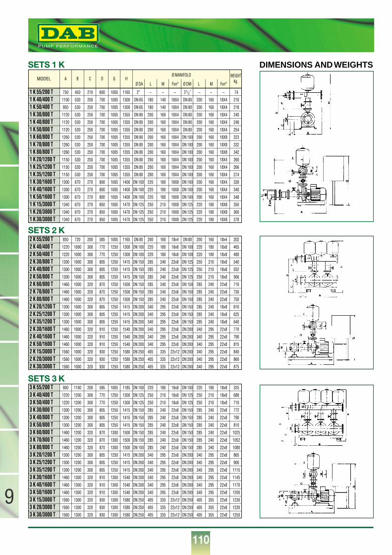
110
9
®
1 K 55/200 T 750 450 210 600 1005 1165 2” – – – 21/2” – – – 74
1 K 40/400 T 1100 530 250 700 1005 1300 DN 65 180 140 18X4 DN 80 200 160 18X4 210
1 K 50/400 T 950 530 250 700 1005 1300 DN 65 180 140 18X4 DN 80 200 160 18X4 218
1 K 30/800 T 1120 530 250 700 1005 1355 DN 80 200 160 18X4 DN 80 200 160 18X4 240
1 K 40/800 T 1120 530 250 700 1005 1355 DN 80 200 160 18X4 DN 80 200 160 18X4 246
1 K 50/800 T 1120 530 250 700 1005 1355 DN 80 200 160 18X4 DN 80 200 160 18X4 254
1 K 60/800 T 1260 530 250 700 1005 1355 DN 80 200 160 18X4 DN 100 200 160 18X8 323
1 K 70/800 T 1260 530 250 700 1005 1355 DN 80 200 160 18X4 DN 100 200 160 18X8 332
1 K 80/800 T 1260 530 250 700 1005 1355 DN 80 200 160 18X4 DN 100 200 160 18X8 342
1 K 20/1200 T 1150 530 250 700 1005 1355 DN 80 200 160 18X4 DN 100 200 160 18X4 260
1 K 25/1200 T 1150 530 250 700 1005 1355 DN 80 200 160 18X4 DN 100 200 160 18X4 266
1 K 35/1200 T 1150 530 250 700 1005 1355 DN 80 200 160 18X4 DN 100 200 160 18X4 274
1 K 30/1600 T 1300 670 270 800 1005 1400 DN 100 220 180 18X8 DN 100 200 160 18X4 330
1 K 40/1600 T 1300 670 270 800 1005 1400 DN 100 220 180 18X8 DN 100 200 160 18X4 340
1 K 50/1600 T 1300 670 270 800 1005 1400 DN 100 220 180 18X8 DN 100 200 160 18X4 348
1 K 15/3000 T 1340 670 270 850 1005 1470 DN 125 250 210 18X8 DN 125 220 180 18X8 350
1 K 20/3000 T 1340 670 270 850 1005 1470 DN 125 250 210 18X8 DN 125 220 180 18X8 360
1 K 30/3000 T 1340 670 270 850 1005 1470 DN 125 250 210 18X8 DN 125 220 180 18X8 378
A B C D G HWEIGHT
Kg.Ø MANIFOLD
Ø DA L M Fxn° Ø DM L M Fxn°
2 K 55/200 T 850 720 200 585 1005 1165 DN 80 200 160 18x4 DN 80 200 160 18x4 202
2 K 40/400 T 1220 1000 300 770 1250 1300 DN 100 220 180 18x8 DN 100 220 180 18x8 465
2 K 50/400 T 1220 1000 300 770 1250 1300 DN 100 220 180 18x8 DN 100 220 180 18x8 480
2 K 30/800 T 1300 1000 300 805 1250 1415 DN 150 285 240 22x8 DN 125 250 210 18x8 540
2 K 40/800 T 1300 1000 300 805 1250 1415 DN 150 285 240 22x8 DN 125 250 210 18x8 552
2 K 50/800 T 1300 1000 300 805 1250 1415 DN 150 285 240 22x8 DN 125 250 210 18x8 566
2 K 60/800 T 1460 1000 320 870 1250 1500 DN 150 285 240 22x8 DN 150 285 240 22x8 710
2 K 70/800 T 1460 1000 320 870 1250 1500 DN 150 285 240 22x8 DN 150 285 240 22x8 730
2 K 80/800 T 1460 1000 320 870 1250 1500 DN 150 285 240 22x8 DN 150 285 240 22x8 750
2 K 20/1200 T 1300 1000 300 805 1250 1415 DN 200 340 295 22x8 DN 150 285 240 18x8 610
2 K 25/1200 T 1300 1000 300 805 1250 1415 DN 200 340 295 22x8 DN 150 285 240 18x8 625
2 K 35/1200 T 1300 1000 300 805 1250 1415 DN 200 340 295 22x8 DN 150 285 240 18x8 640
2 K 30/1600 T 1460 1000 320 910 1250 1540 DN 200 340 295 22x8 DN 200 340 295 22x8 770
2 K 40/1600 T 1460 1000 320 910 1250 1540 DN 200 340 295 22x8 DN 200 340 295 22x8 790
2 K 50/1600 T 1460 1000 320 910 1250 1540 DN 200 340 295 22x8 DN 200 340 295 22x8 815
2 K 15/3000 T 1560 1000 320 930 1250 1580 DN 250 405 335 22x12 DN 200 340 295 22x8 840
2 K 20/3000 T 1560 1000 320 930 1250 1580 DN 250 405 335 22x12 DN 200 340 295 22x8 860
2 K 30/3000 T 1560 1000 320 930 1250 1580 DN 250 405 335 22x12 DN 200 340 295 22x8 875
3 K 55/200 T 900 1100 200 595 1005 1185 DN 100 220 180 18x8 DN 100 220 180 18x8 325
3 K 40/400 T 1220 1200 300 770 1250 1300 DN 125 250 210 18x8 DN 125 250 210 18x8 688
3 K 50/400 T 1220 1200 300 770 1250 1300 DN 125 250 210 18x8 DN 125 250 210 18x8 710
3 K 30/800 T 1300 1200 300 805 1250 1415 DN 150 285 240 22x8 DN 150 285 240 22x8 772
3 K 40/800 T 1300 1200 300 805 1250 1415 DN 150 285 240 22x8 DN 150 285 240 22x8 790
3 K 50/800 T 1300 1200 300 805 1250 1415 DN 150 285 240 22x8 DN 150 285 240 22x8 810
3 K 60/800 T 1460 1200 320 870 1300 1500 DN 150 285 240 22x8 DN 150 285 240 22x8 1025
3 K 70/800 T 1460 1200 320 870 1300 1500 DN 150 285 240 22x8 DN 150 285 240 22x8 1052
3 K 80/800 T 1460 1200 320 870 1300 1500 DN 150 285 240 22x8 DN 150 285 240 22x8 1080
3 K 20/1200 T 1300 1200 300 805 1250 1415 DN 200 340 295 22x8 DN 200 340 295 22x8 865
3 K 25/1200 T 1300 1200 300 805 1250 1415 DN 200 340 295 22x8 DN 200 340 295 22x8 900
3 K 35/1200 T 1300 1200 300 805 1250 1415 DN 200 340 295 22x8 DN 200 340 295 22x8 1115
3 K 30/1600 T 1460 1300 320 910 1300 1540 DN 200 340 295 22x8 DN 200 340 295 22x8 1145
3 K 40/1600 T 1460 1300 320 910 1300 1540 DN 200 340 295 22x8 DN 200 340 295 22x8 1170
3 K 50/1600 T 1460 1300 320 910 1300 1540 DN 200 340 295 22x8 DN 200 340 295 22x8 1200
3 K 15/3000 T 1560 1300 320 930 1300 1580 DN 250 405 335 22x12 DN 250 405 355 22x8 1230
3 K 20/3000 T 1560 1300 320 930 1300 1580 DN 250 405 335 22x12 DN 250 405 355 22x8 1230
3 K 30/3000 T 1560 1300 320 930 1300 1580 DN 250 405 335 22x12 DN 250 405 355 22x8 1250
DIMENSIONS AND WEIGHTSSETS 1 K
SETS 2 K
SETS 3 K
MODEL
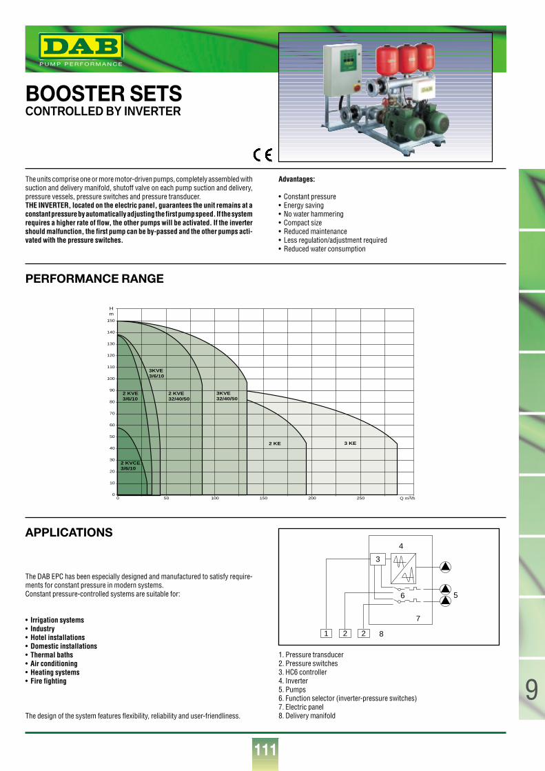
111
9
®
BOOSTER SETSCONTROLLED BY INVERTER
The units comprise one or more motor-driven pumps, completely assembled withsuction and delivery manifold, shutoff valve on each pump suction and delivery,pressure vessels, pressure switches and pressure transducer.THE INVERTER, located on the electric panel, guarantees the unit remains at aconstant pressure by automatically adjusting the first pump speed. If the systemrequires a higher rate of flow, the other pumps will be activated. If the invertershould malfunction, the first pump can be by-passed and the other pumps acti-vated with the pressure switches.
Advantages:
• Constant pressure• Energy saving• No water hammering• Compact size• Reduced maintenance• Less regulation/adjustment required• Reduced water consumption
The DAB EPC has been especially designed and manufactured to satisfy require-ments for constant pressure in modern systems.Constant pressure-controlled systems are suitable for:
• Irrigation systems• Industry• Hotel installations• Domestic installations • Thermal baths• Air conditioning• Heating systems• Fire fighting
The design of the system features flexibility, reliability and user-friendliness.
1. Pressure transducer2. Pressure switches3. HC6 controller4. Inverter5. Pumps6. Function selector (inverter-pressure switches)7. Electric panel8. Delivery manifold
PERFORMANCE RANGE
APPLICATIONS
2 KVE3/6/10
2 KVCE3/6/10
3KVE3/6/10
2 KVE32/40/50
3KVE32/40/50
2 KE 3 KE
0 50 100 150 200 250 Q m3/h0
10
20
30
40
50
60
70
80
90
100
110
120
130
140
150
Hm
1 2 2
3
4
6
7
8
5
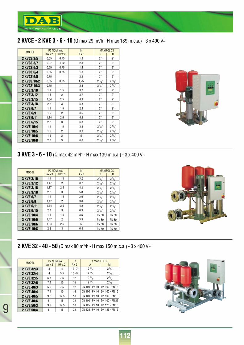
112
9
®
2 KVCE - 2 KVE 3 - 6 - 10 (Q max 29 m3/h - H max 139 m.c.a.) - 3 x 400 V~
3 KVE 3 - 6 - 10 (Q max 42 m3/h - H max 139 m.c.a.) - 3 x 400 V~
2 KVE 32 - 40 - 50 (Q max 86 m3/h - H max 150 m.c.a.) - 3 x 400 V~
2 KVE 32/32 KVE 32/42 KVE 32/52 KVE 32/62 KVE 40/32 KVE 40/42 KVE 40/52 KVE 40/62 KVE 50/32 KVE 50/4
MODELkW x 2 HP x 2 A MA x 2
3
4
5,5
7,4
5,5
7,4
9,2
11
9,2
11
4
5,5
7,5
10
7,5
10
12,5
15
12,5
15
12 - 7
16 - 9
12
15
12
15
18
22
18
22
2 1/22 1/22 1/22 1/2
DN 100 - PN 10
DN 100 - PN 10
DN 100 - PN 10
DN 100 - PN 10
DN 125 - PN 10
DN 125 - PN 10
2 1/22 1/22 1/22 1/2
DN 100 - PN 16
DN 100 - PN 16
DN 100 - PN 16
DN 100 - PN 25
DN 125 - PN 16
DN 125 - PN 16
P2 NOMINAL In ø MANIFOLDS
P2 NOMINAL In MANIFOLDS
2 KVCE 3/52 KVCE 3/72 KVCE 6/32 KVCE 6/42 KVCE 6/52 KVCE 10/22 KVCE 10/32 KVE 3/102 KVE 3/122 KVE 3/152 KVE 3/182 KVE 6/72 KVE 6/92 KVE 6/112 KVE 6/152 KVE 10/42 KVE 10/52 KVE 10/62 KVE 10/8
0,55
0,97
0,55
0,55
0,75
0,55
0,75
1,1
1,5
1,84
2,2
1,1
1,5
1,84
2,2
1,1
1,5
1,5
2,2
1,1
1,47
1,87
2,2
1,1
1,47
1,84
2,2
1,1
1,47
1,84
2,2
1,5
2
2,5
3
1,5
2
2,5
3
1,5
2
2,5
3
3,2
3,7
4,3
5,8
2,9
3,6
4,2
6,3
3,5
3,9
5
6,8
2 1/2”
2 1/2”
2 1/2”
2 1/2”
2 1/2”
2 1/2”
2 1/2”
2 1/2”
PN 80
PN 80
PN 80
PN 80
2 1/2”
2 1/2”
2 1/2”
2 1/2”
2 1/2”
2 1/2”
2 1/2”
2 1/2”
PN 80
PN 80
PN 80
PN 80
0,75
1,32
0,75
0,75
1
0,75
1
1,5
2
2,5
3
1,5
2
2,5
3
1,5
2
2
3
1,8
2,3
1,4
1,8
2,2
1,75
2,3
3,2
3,7
4,3
5,8
2,9
3,6
4,2
6,3
3,5
3,9
5
6,8
2”
2”
2”
2”
2”
2 1/2”
2 1/2”
2”
2”
2”
2”
2”
2”
2”
2”
2 1/2”
2 1/2”
2 1/2”
2 1/2”
2”
2”
2”
2”
2”
2 1/2”
2 1/2”
2”
2”
2”
2”
2”
2”
2”
2”
2 1/2”
2 1/2”
2 1/2”
2 1/2”
MODELkW x 2 HP x 2 S DA x 2
P2 NOMINAL In MANIFOLDS
3 KVE 3/103 KVE 3/123 KVE 3/153 KVE 3/183 KVE 6/73 KVE 6/93 KVE 6/113 KVE 6/153 KVE 10/43 KVE 10/53 KVE 10/63 KVE 10/8
MODELkW x 3 HP x 3 S DA x 3
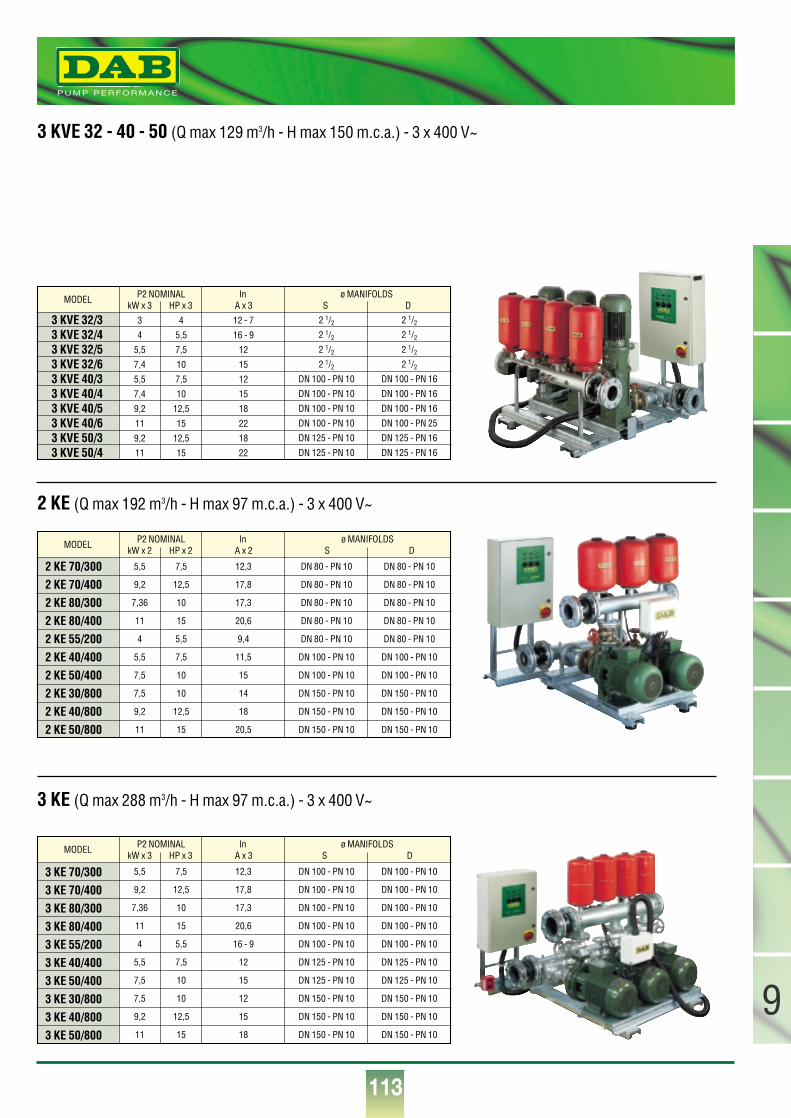
113
9
®
3 KVE 32 - 40 - 50 (Q max 129 m3/h - H max 150 m.c.a.) - 3 x 400 V~
2 KE (Q max 192 m3/h - H max 97 m.c.a.) - 3 x 400 V~
3 KE (Q max 288 m3/h - H max 97 m.c.a.) - 3 x 400 V~
3 KVE 32/33 KVE 32/43 KVE 32/53 KVE 32/63 KVE 40/33 KVE 40/43 KVE 40/53 KVE 40/63 KVE 50/33 KVE 50/4
MODELkW x 3 HP x 3 S DA x 3
3
4
5,5
7,4
5,5
7,4
9,2
11
9,2
11
4
5,5
7,5
10
7,5
10
12,5
15
12,5
15
12 - 7
16 - 9
12
15
12
15
18
22
18
22
2 1/22 1/22 1/22 1/2
DN 100 - PN 10
DN 100 - PN 10
DN 100 - PN 10
DN 100 - PN 10
DN 125 - PN 10
DN 125 - PN 10
2 1/22 1/22 1/22 1/2
DN 100 - PN 16
DN 100 - PN 16
DN 100 - PN 16
DN 100 - PN 25
DN 125 - PN 16
DN 125 - PN 16
P2 NOMINAL In ø MANIFOLDS
2 KE 70/3002 KE 70/4002 KE 80/3002 KE 80/4002 KE 55/2002 KE 40/4002 KE 50/4002 KE 30/8002 KE 40/8002 KE 50/800
MODELkW x 2 HP x 2 S DA x 2
3 KE 70/3003 KE 70/4003 KE 80/3003 KE 80/4003 KE 55/2003 KE 40/4003 KE 50/4003 KE 30/8003 KE 40/8003 KE 50/800
MODELkW x 3 HP x 3 S DA x 3
5,5
9,2
7,36
11
4
5,5
7,5
7,5
9,2
11
7,5
12,5
10
15
5,5
7,5
10
10
12,5
15
12,3
17,8
17,3
20,6
16 - 9
12
15
12
15
18
DN 100 - PN 10
DN 100 - PN 10
DN 100 - PN 10
DN 100 - PN 10
DN 100 - PN 10
DN 125 - PN 10
DN 125 - PN 10
DN 150 - PN 10
DN 150 - PN 10
DN 150 - PN 10
DN 100 - PN 10
DN 100 - PN 10
DN 100 - PN 10
DN 100 - PN 10
DN 100 - PN 10
DN 125 - PN 10
DN 125 - PN 10
DN 150 - PN 10
DN 150 - PN 10
DN 150 - PN 10
5,5
9,2
7,36
11
4
5,5
7,5
7,5
9,2
11
7,5
12,5
10
15
5,5
7,5
10
10
12,5
15
12,3
17,8
17,3
20,6
9,4
11,5
15
14
18
20,5
DN 80 - PN 10
DN 80 - PN 10
DN 80 - PN 10
DN 80 - PN 10
DN 80 - PN 10
DN 100 - PN 10
DN 100 - PN 10
DN 150 - PN 10
DN 150 - PN 10
DN 150 - PN 10
DN 80 - PN 10
DN 80 - PN 10
DN 80 - PN 10
DN 80 - PN 10
DN 80 - PN 10
DN 100 - PN 10
DN 100 - PN 10
DN 150 - PN 10
DN 150 - PN 10
DN 150 - PN 10
P2 NOMINAL In ø MANIFOLDS
P2 NOMINAL In ø MANIFOLDS

Edi
zion
e 20
00 –
0018
.000
.81
Sales Export dept.: Tel. 049/9048873 - Fax 049/9048888Tel. 049/9048874 - Fax 049/9048888Tel. 049/9048875 - Fax 049/9048888
Customer Technical Assistance:Tel. 049/9048911 - Fax 049/9048920
DAB PUMPS S.p.A. via M. Polo, 14 - 35035 Mestrino (PD)Tel. +39-049-9048811 - Fax +39-049-9048847http://www.dabpumps.com
®
P U M P P E R F O R M A N C E