Genelec AIW25 Active In-Wall Loudspeaker · PDF fileGenelec AIW25 Active In-Wall Loudspeaker...
6
Genelec AIW25 Active In-Wall Loudspeaker Operating Manual AIW25
-
Upload
hoangxuyen -
Category
Documents
-
view
217 -
download
1
Transcript of Genelec AIW25 Active In-Wall Loudspeaker · PDF fileGenelec AIW25 Active In-Wall Loudspeaker...

Genelec AIW25Active In-Wall Loudspeaker
Operating ManualAIW25
Genelec AIW25 Active In-Wall Loudspeaker
The Genelec AIW25 Active In-Wall loud-speaker system consists of a two-way loudspeaker enclosure and a matched remote amplifier module, RAM2. It has been designed to the same rigorous standards as Genelec’s high-performance HT series active Home Theater loudspeakers. No other in-wall loudspeaker in this size class can match the low distortion, neutrality and high sound pressure capability of Genelec AIW25. The AIW25 can be used in the most demanding applications, like the main L-C-R array of a Home Theater system, critical Stereo listen-ing or rear/side channels of a medium sized, state-of-the-art Home Theater.
UnpackingA Genelec AIW25 set includes the following items. Check that nothing is missing or dam-aged in transit. If there is a problem with the product, contact your local Genelec dealer.
• AIW25 loudspeaker enclosure.• Grill insert• AIW25 cardboard cut-out template• Loudspeaker painting mask• RAM2 amplifier unit• Mains power cable• Two M4 Phillips 2 screws• This Operating Manual
Installation
Genelec recommends that you use the ser-vices of an authorized installation special-ist or other competent and experienced installation company for the installation of the AIW25 system. Ask your local Genelec dealer for recommended installation compa-nies in your region.
Matching loudspeakers and amplifiers
Each AIW25 loudspeaker has been factory calibrated for optimum performance with the RAM2 amplifier it is shipped with. Never mix these matched amplifier-loudspeaker sys-tems in the installation process. The matching units are marked with the same ID number.
Loudspeaker placementGenelec AIW25 loudspeakers are equipped with Genelec’s proprietary Directivity Con-trol Waveguide™ (DCW™). One of the main characteristics of the DCW™ technology is that the loudspeakers give a very even and consistent frequency response over a large listening area. A secondary function of the DCW™ is to reduce the off-axis radiated sound energy, thereby minimizing the reflec-tions from the side walls, floor and ceiling.
This results in a precise and stable sound image.
If the AIW25 loudspeakers are used in an application where their capability for precise sound imaging is needed, such as the front channels of a Surround Sound system or a Stereo system, we recommend that the loud-speakers are placed as far away from cor-ners or other walls and reflective surfaces as possible. The loudspeakers should be placed symmetrically in relation to the listening posi-tion and there should be no obstructions between the loudspeaker and the listener. This guarantees clear dialogue in films and a good sound stage image with music. Figure 2 shows a Left-Center-Right arrangement that works well both as Surround Sound front channels and a Stereo pair.
If you prefer a diffuse sound field, which is less critical to the listening position and gives only a vague sense of direction, for instance in a rear/side channel setup in a Home Theater system, you may actually benefit from the acoustical reflections from nearby boundaries. In this case, place the loudspeakers close to the ceiling or another wall, or have them face away from the lis-tening position, so that the proportion of reflected sound increases.
Figure 2. Front loudspeaker placement
Figure 3. Connecting the loudspeaker cable
Cable gauge Max. length
2,0 mm2 (14 AWG) 30 m (100 ft)
3,3 mm2 (12 AWG) 40 m (130 ft)
5,3 mm2 (10 AWG) 60 m (200 ft)
Table 1. Recommended cable thicknesses for different lengths of cable
Figure 4. Screws for tightening the mounting tabs are located at each corner of the front baffle
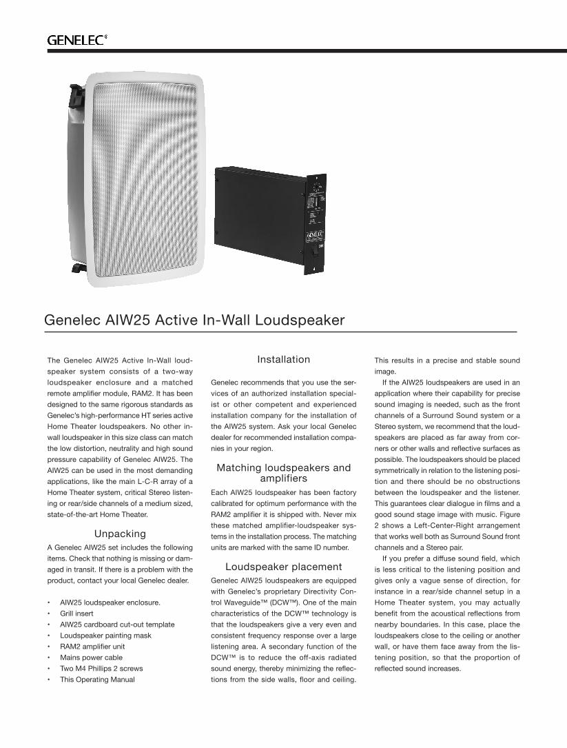
BALANCED SIGNALINPUT CONNECTOR
BALANCED LINKOUT CONNECTOR
UNBALANCED SIGNALINPUT CONNECTOR
COMBINED CONNECTOR, PIN SEQUENCE FROM TOP:
1. REMOTE 1(NOT ACTIVE IN UNITS SOLD IN EUROPE)2. REMOTE 2 (NOT ACTIVE IN UNITS SOLD IN EUROPE)3. TWEETER -4. TWEETER +5. WOOFER -6. WOOFER +
MAINS INPUT
Figure 1. RAM2 amplifier back panel view
CablingThe RAM2 amplifier unit has separate power amplifiers for the tweeter and woofer. Accordingly, a 4-conductor cable needs to be run between the amplifier and the loud-speaker enclosure. Two cable connectors are supplied with the loudspeaker system, a six-pole connector to fit the connector on the amplifier and a four-pole connector to fit the respective input on the top of the loud-speaker enclosure.
Attach the cables to the green connec-tors provided with the kit. Be sure to main-tain correct polarity when connecting the cables and be extra careful not to mix the tweeter and woofer cables. The correct pin sequences are marked on the amplifier and loudspeaker enclosure. Starting from the top, the first two poles on the amplifier con-nector are for the 12 V remote control volt-age, pole 3 for tweeter -, pole 4 for tweeter +, pole 5 for woofer - and pole 6 for woofer +. Respectively, the pole sequence on the loudspeaker connector is 1 tweeter -, 2 tweeter +, 3 woofer - and 4 woofer +. Secure
the cable to the strain relief tie next to the loudspeaker connector.
Use a good quality 4-conductor cable and make the cable runs as short as possible. See Table 1 for recommended cable gauges. The connectors accept a cable up to 6 mm2
(9 gauge) thick. If you are installing the AIW25 enclosure
to an existing wall, examine the walls thor-oughly for the shortest and least obstructed cable route. Be careful to avoid cutting or drilling into electrical wires, ventilation or water pipes. These are often visible in the attic, basement or crawl space below the floor. All of this is of course much easier when the installation takes place in an unfin-ished wall where the wall structure is still open. In both cases it is a good idea to route the loudspeaker cables away from electric, video or phone cables, which might induce hum into the loudspeaker system.
Painting the loudspeakersThe loudspeaker enclosure flange and the metal mesh grill can be spray painted to match the wall colour. Do not paint the loudspeaker front baffle and drivers, or try to paint the grill while it is attached to the loudspeaker. Paint the enclosure and the
grill separately with a thin spray. Do not use brushes or rollers. Be careful to avoid clog-ging the grill with paint.
Attach the cardboard painting mask on the loudspeaker front baffle before spraying the loudspeaker to protect the drivers and front baffle from smearing.
Installing the AIW25 loudspeaker enclosure
For new construction installs, we recom-mend planning the loudspeaker placement at an early stage and using the optional Genelec New Construction Brackets (order code 272-0030) for marking the desired loca-tions. The brackets can be nailed or screwed to the studs to show the drywall installers the places where holes for the loudspeakers are to be located.
When installing the enclosure in an exist-ing wall, use the cardboard wall cut-out tem-plate to find the best location. The template also shows the position of the loudspeaker drivers and acoustic axis, so you can easily find the placement that brings them to the optimum position as outlined in chapter “Loudspeaker placement”.
Examine the wall structure carefully to find a clearly unobstructed location for the loud-

Figure 6. Installing the RAM2 amplifier module to the optional RM2 rack mount adapter.
Figure 5. Installing the metal support to the RAM2 amplifier module for placement on a solid aurface.
speaker. The loudspeaker enclosure requires a minimum of 98 millimeters (3 27/32”) of free depth measured from the outer surface of the sheetrock. Also note that the enclosure flange is wider and taller than the hole and requires about 20 millimeters (3/4”) of smooth wall surface around all sides of the hole.
When you have found a good location, check that the template is level and trace the hole onto the wall with a pencil along the out-line of the template. If you are not sure that the chosen part of wall is free from obstructions, you can start by making a smaller hole at the center of the marked area through which you can probe the inside of the wall. Use a dry-wall saw and make the first cut at a 45° angle toward the center of the hole so you can put the cut piece back in if the location is unsuita-ble. If you find no obstructions, you can make the final cut along the marked lines.
If you have already connected the RAM2 amplifier units to the decoder or other signal source, select the loudspeaker enclosure that has the same ID number as the ampli-fier it will be driven by. Connect the loud-speaker cables as described above in chap-ter “Cabling”.
Loosen the screws on the four mounting tabs on the AIW25 enclosure a few turns to allow the tabs to turn.
Lift the AIW25 enclosure into the hole and turn the screws clockwise so that the mount-ing tabs rotate outwards. Continue tighten-ing the screws until the sheetrock is firmly clamped between the mounting tabs and the enclosure flange. If necessary, a secondary support line can be attached to the tab on the top side of the enclosure.
Connecting the RAM2 amplifier
The RAM2 amplifier is designed to be con-nected to a line level output of a preamplifier, Surround Sound processor or other low level source. NOTE! Never connect the RAM2 to a loudspeaker level output of a power amplifier!
Check that the amplifier’s serial number matches that of the AIW25 loudspeaker enclosure which it will power. If the loud-speaker enclosures are not yet installed, make a note of which amplifier is connected to each channel so you can find the cor-rect AIW25 loudspeaker enclosure for every amplifier. Connect the 12 V remote control cables (not applicable in Europe) and loud-
speaker cables as described above in chap-ter “Cabling”.
The RAM2 has two parallel 10 kOhm input connectors: a balanced female XLR and an unbalanced RCA. There is also a male XLR connector that can be used for daisy-chain-ing several systems together. For long cable connection lengths (>10 m or >30 ft) a bal-anced line connection is recommended as it offers better immunity to external interfer-ence. However, the RCA connection method is more commonly available and usually works as well for shorter connection lengths in less electrically noisy environments. Do not use both inputs at the same time. Con-sult your Genelec dealer for the choice of signal cables.
Space requirement for the RAM2 amplifier
The dual 40 W power amplifiers of a RAM2 unit generate a considerable amount of heat when used at full power. To avoid overheat-ing, ensure that there is good airflow around the amplifier and no external heat sources close to it. We recommend installing the RAM2 into a well ventilated equipment rack using its dedicated RM2 rack mount kit which allows airflow through the ventilation holes on the bottom and top of the amplifier box. The amplifier must always be installed in an upright position, never flat on its side.
Sufficient cooling for the amplifier must be arranged at all times. As a general rule, the ambient temperature around the amplifier must not exceed 35 degrees Celsius (95°F). The ventilation openings on the amplifier box must not be blocked and a free space of 1 U (=1.75" or 45 mm) must be left above the amplifier when installed. This space must be sufficiently ventilated to maintain
the temperature below the aforementioned maximum level.
If the RAM2 amplifier is placed on a shelf or other solid surface, the metal sup-port provided with the amplifier must be attached to the lower part of the ampli-fier front panel with an M4 screw. This improves the stability of the amplifier and provides sufficient clearance for air circula-tion below the amplifier.
Mounting the RAM2 amplifier to an equipment rack
We recommend that you use the Genelec RM2 rack mount adapter when installing the RAM2 amplifier in an equipment rack. Make sure that the space above and below the RAM2 is uncluttered and there is a space of 100 mm (4”) or more behind the ampli-fier. The space behind the amplifier must be well ventilated. If the temperature inside the rack is likely to rise close to RAM2’s maxi-mum ambient temperature of 35° C (95° F), we recommend installing ventilation fans to ensure that the thermal protection is not activated prematurely.
Attach the RAM2 to the RM2 rack mount with two M4 screws provided with the rack mount kit. The screws go through the holes on the front panel of the amplifier. Each RM2 can take eight RAM2 amplifiers. Blanking plates are provided to cover empty spaces in the rack if fewer RAM2’s are installed.
Setting the input sensitivityThe input sensitivity of each loudspeaker can be made to match that of the decoder or other source by use of the input sensitiv-ity control on the amplifier’s front panel. A small screwdriver is needed for the adjust-ment. The manufacturer default setting for

Bass Tilt Treble Tilt
Half space factory default setting 0 dB (All OFF) 0 dB (All OFF)
Well damped (dead sounding) room 0 dB (All OFF) 0 dB (All OFF)
Normal room 0 dB (All OFF) ON
Highly reflective (live sounding) room -2 dB ON ON
Double corner (wall/wall or wall/ceiling) placement -2 dB ON 0 dB (All OFF)
Triple corner (wall/wall/ceiling) -4 dB ON 0 dB (All OFF)
Table 2. Suggested Tone Control settings for some typical situations
this control is -6 dBu (fully clockwise) which gives SPL of 100 dB @1m with -6 dBu input level. Note that to get the full output level of 100 dB SPL per unit, an input level of +4 dBu (1.22 V) is needed in this setting. Most pre-amplifiers are capable of this output level.
Setting the room response controls
The acoustic response of the system may have to be adjusted to match the acoustic environment and personal taste. See Table 2 for suggested room response control set-tings in differing acoustic environments. If the sound is found subjectively too bright, set ‘TREBLE TILT’ to “ON” (-2 dB), if too bass heavy, you can choose between three atten-uation levels (-2, -4 or -6 dB) by switching on the corresponding ‘BASS TILT’ switch.
The "BASS ROLL-OFF" switch activates an 85 Hz high-pass filter, which can be used for matching the loudspeaker response to a correspondingly low-pass filtered subwoofer.
The manufacturer default settings for all controls are ‘All Off’ to give a flat response in half space, i.e. when the loudspeaker has been installed in a wall. Always start adjust-ment by setting all switches to the ‘OFF’ position. The "BASS TILT" switches are not cumulative. If more than one switch is set to ‘ON’ the attenuation value is not accurate.
Using Autostart and Remote Control functions
“AUTOSTART” and “REMOTE CONTROL” functions described in this chapter are not available on units sold in Europe.
In daily use, the RAM2 amplifier can be switched to Standby mode to save energy by activating the signal sensing Autostart function or by using a 12 V trigger voltage from the decoder. These functions are not available in units sold in EU countries. If the system is left unused for several days, we recommend that you power it down using the RAM2’s main power switch or a central power switch if one has been installed.
The Autostart function is activated by turn-ing switch 2 (AUTOSTART) on the amplifier front panel to “ON”. Autostart turns the ampli-fier to “STANDBY” mode if there is no signal present for about 30 minutes. When the signal returns the amplifier switches on immediately and the loudspeaker functions normally.
If you are using a 12 V trigger type remote control to switch the RAM2 between “STANDBY” or “ON” modes (see chap-ter “Connecting the RAM2 amplifier”), turn switch 1 (REMOTE CONTROL), on the amplifier panel to “ON”. This activates the remote control function. In this setting the remote control will override the Autostart function. If you want to use Autostart, turn the “REMOTE CONTROL” switch to “OFF”.
Status indicator LEDThe status indicator LED on the RAM2 changes colour to indicate amplifier status. If the LED is yellow, it indicates that the amplifier is in “STANDBY” mode. When the amplifier is switched to “ON” mode, the LED changes to green colour.
Automatic protection circuitsThe AIW25 system has protection circuits against loudspeaker driver thermal overload and amplifier overheating. The protection system resets automatically so the user only has to turn the input level down to ensure that it does not reactivate.
Driver thermal overload protection pro-tects the drivers from damage caused by prolonged overdriving with excessively high or distorted signal. If this occurs, the circuit automatically reduces playback volume. To avoid this, lower the listening volume if the sound becomes harsh and distorted at high sound pressure levels.
When activated, the amplifier thermal protection mutes the amplifier for very short periods of time, making the sound harsh and distorted. Let the amplifier cool down and check that there is sufficient clear-ance around the amplifier for cooling (see chapters “Space requirement for the RAM2 amplifier” and “Mounting the RAM2 amplifier to an equipment rack” above). If the prob-lem persists, consult your Genelec dealer or
Home Theater Installation company for an improved cooling solution for your equip-ment cabinet or rack.
MaintenanceThere are no user serviceable parts within the loudspeaker or the amplifier. Any main-tenance or repair should only be undertaken by qualified service personnel.
Safety considerations• Do not expose the loudspeaker or ampli-fier to water or moisture. Do not place any objects filled with liquid, such as vases on or near them. • Do not place naked flame sources like lighted candles on or near the loudspeaker or amplifier.• Servicing and adjustment must only be performed by qualified service personnel. • Opening the amplifier is strictly prohibited except by qualified service personnel. • Always use a mains power connection and cable with protective earth. Failing to do this may lead to personal injury.• Note that the amplifier is not completely disconnected from the AC mains service unless the mains power cord is removed from the amplifier or the mains outlet.• Switch off the mains power from the amplifier if the system is not used for long periods of time.
WARNING!This equipment is capable of delivering Sound Pressure Levels in excess of 85 dB, which may cause permanent hearing damage.
GuaranteeThis product is supplied with a two year guarantee against manufacturing faults or defects that might alter the performance of the unit. Refer to supplier for full sales and guarantee terms.

AIW25 Operating Manual
Genelec Document D0064R001b. Copyright Genelec Oy 3.2017. All data subject to change without prior notice www.genelec.comInternational enquiries: Genelec, Olvitie 5FIN-74100, Iisalmi, FinlandPhone +358 17 83881Fax +358 17 812 267Email [email protected]
In the U.S. please contact: Genelec, Inc., 7 Tech CircleNatick, MA 01760, USAPhone +1 508 652 0900Fax +1 508 652 0909Email [email protected]
In Sweden please contact Genelec SverigeEllipsvägen 10BBox 2036, S-127 02 SkärholmenPhone +46 8 449 5220Fax +46 8 708 7071Email [email protected]
In China please contact: Beijing Genelec Audio Co. Ltd.B33-101, Universal Busines ParkNo. 10 Jiuxianqiao RoadChaoyang District100015 Beijing, ChinaPhone +86 0 5823 2014, 400 700 1978
AMPLIFIER SECTIONSYSTEM SPECIFICATIONSAIW25
Lower cut-off frequency, –3 dB ≤ 68 Hz
Upper cut-off frequency, –3 dB > 20 kHz
Free field frequency response 70 Hz – 18 kHz (± 2.5 dB)
Maximum short term sine wave acoustic output on axis in half space, averaged from 100 Hz to 3 kHz
@ 1 m > 100 dB SPL
Maximum peak acoustic output per pair with music material
@ 1 m > 110 dB SPL
Self generated noise level in half space at 1 m on axis (A-weighted)
≤ 10 dB
Harmonic distortion at 85 dB SPL at 1 m on axis
Freq: 70…200 Hz > 200 Hz
< 3%< 0.5 %
DriversBassTreble
130 mm (5") cone 19 mm (3/4") metal dome
WeightLoudspeaker enclosure Amplifier
3.7 kg (8.1 lb) 2.2 kg (4.8 lb)
Dimensions Loudspeaker enclosure max. height Loudspeaker enclosure max. width Loudspeaker enclosure max. depth Cutout height Cutout width Minimum free depth measured from the surface of the wall Amplifier height Amplifier widthAmplifier depth*
*Note that the cable connectors require at least 100 mm (4”) of space behind the amplifier
360 mm (143/16”)267 mm (101/2”) 104 mm (43/32”) 334 mm (135/32”) 240 mm (97/16”) 98 mm (327/32”) 177 mm (631/32”) (4U) 54 mm (21/8”) 260 mm (101/4”)
AIW25
Bass amplifier short term output power Treble amplifier short term output power(Long term output power is limited by driver unit protection circuitry)
40 W at 8 Ohm load40 W at 8 Ohm load
Amplifier system THD at nominal output ≤ 0.08 %
Mains voltage 100, 120 or 230 V
Power consumption (average)IdleFull output
10 VA80 VA
Recommended loudspeaker cable gauge 0.8 to 5.0 mm2 (18 to 10 AWG)
Standby/On switching by signal sensing Autostart function or +12 V DC remote control is not available in units sold in Europe.
CROSSOVER SECTIONAIW25
Connectors:XLR female input, balanced 10 kOhmRCA female input, unbalanced 10 kOhm “LINK OUT” XLR male output, balanced 10 kOhm
pin 1 gnd, pin 2 +, pin 3 - pin +, ring gnd pin 1 gnd, pin 2 +, pin 3 -
Input level for 100 dB SPL output at 1 m -6 dBu
Input Sensitivity adjustment range +6 dBu to -6 dBu
Crossover frequency, Bass/Treble 3.0 kHz
Treble Tilt control operating range 0 to –2 dB @ 15 kHz
Bass Tilt control operating range in –2 dB steps
From 0 to -6 dB @ 100 Hz
Bass Roll-Off control -6 dB @ 85 Hz
The ‘CAL’ position is with all tone controls set to ‘off’ and the input sensitiv-ity control to maximum (fully clockwise).
Figure 7. The main dimensions of the AIW25 loudspeaker enclosure Figure 8. The main dimensions of the RAM2 amplifier