GENALE GD-6 HYDROPOWER PROJECT FEASIBILITY STUDY Final … · 2018-04-02 · GENALE GD-6 HYDROPOWER...
248
THE FEDERAL DEMOCRATIC REPUBLIC OF ETHIOPIA MINISTRY OF WATER RESOURCES GENALE GD-6 HYDROPOWER PROJECT FEASIBILITY STUDY Final Report Volume 1 Main Report May 2009 in association with
Transcript of GENALE GD-6 HYDROPOWER PROJECT FEASIBILITY STUDY Final … · 2018-04-02 · GENALE GD-6 HYDROPOWER...

THE FEDERAL DEMOCRATIC REPUBLIC OF ETHIOPIA
MINISTRY OF WATER RESOURCES
GENALE GD-6 HYDROPOWER PROJECT FEASIBILITY STUDY
Final Report
Volume 1 Main Report
May 2009
in association with
Federal Democratic Republic of Ethiopia – Ministry of Water Resources Volume 1 Feasibility Study of Genale GD-6 Hydropower Project Page i
GD-6 Feaisbility Report Final Volume 1.doc NORPLAN – NORCONSULT JV in Association with Shebelle Engineering
Structure of the Feasibility Report Volume 1 Main Report
Volume 1 is the Main Report, a stand-alone volume that gives the reader a complete picture of the recommended project and the main results of the study. Volume 1 starts with an Executive Summary.
Details and data sheets of studies and analyses within the various fields (geology, hydrology, sediments, simulations, hydraulic analysis, economic analyses, etc.) are given in separate volumes/annexes.
Volume 2 Project Drawings of Genale GD-6 HPP
Series A: General drawings Series B: Civil project structures Series C: Mechanical and electrical equipment Series D: Transmission lines and power system Series E: Geology and ground conditions Series F: Construction schedule Series G: Access roads Volume 3 Supporting Documents Part 1 - Various analyses
Annex 3 A: Reservoir operation and power production Annex 3 B: Hydrology and sediment transport Annex 3 C: Hydraulic analyses. Optimisation. Annex 3 D: Access roads Annex 3 E: Power system and transmission lines Annex 3 F: Surveying and mapping Annex 3 G: Detailed cost estimate Annex 3 H: Economic and financial analyses Volume 4 Supporting Documents Part 2- Geology and Geotechnics.
Ground conditions and ground engineering.
Annex 4 A: Geological mapping – field report with photographs Annex 4 B: Rotary core drillings – core logs Annex 4 C: Core box photographs Annex 4 D: Field permeability tests Annex 4 E: Laboratory test results Annex 4 F: Seismic Hazard Assessment Report Volume 5 Environmental Impact Assessment

Federal Democratic Republic of Ethiopia – Ministry of Water Resources Volume 1 Feasibility Study of Genale GD-6 Hydropower Project Page ii
GD-6 Feasibility Report Final Volume 1.doc NORPLAN – NORCONSULT JV in Association with Shebelle Engineering
TABLE OF CONTENTS - VOLUME 1
LIST OF TABLES ................................................................................................................................ VIII
LIST OF FIGURES ................................................................................................................................. XI
LIST OF REFERENCES ...................................................................................................................... XIII
LIST OF ABBREVIATIONS AND ACRONYMS .................................................................................. XIV
1 EXECUTIVE SUMMARY ........................................................................................................... 1-1
1.1 Introduction ................................................................................................................................. 1-1 1.2 Key results of study .................................................................................................................... 1-1
1.2.1 Power production and Cost .............................................................................................................1-1 1.2.2 Base Case, Economic and Financial analysis. ................................................................................1-4 1.2.3 Environmental impacts ....................................................................................................................1-6
1.3 Genale GD-6 - Brief description of the recommended project ................................................... 1-8 1.3.1 Project location................................................................................................................................1-8 1.3.2 Civil structures and reservoir ...........................................................................................................1-9 1.3.3 Electromechanical equipment ....................................................................................................... 1-10 1.3.4 Small Hydropower Plant ................................................................................................................ 1-11
1.4 Key project characteristics for Genale GD-6 ........................................................................... 1-12
2 STUDY BACKGROUND ............................................................................................................ 2-1
2.1 Project location ........................................................................................................................... 2-1 2.2 Previous studies on Genale GD-6 Hydropower Project,............................................................ 2-2 2.3 Objective for the present study .................................................................................................. 2-2
3 GENALE GD-6 – PROJECT DESCRIPTION ............................................................................ 3-1
3.1 Genale GD-6 - Arrangement of project structures ..................................................................... 3-1 3.2 Genale GD-6. Layout changes. ................................................................................................. 3-2 3.3 Genale GD-6 - Dam and reservoir ............................................................................................. 3-3
3.3.1 Dam axis selection ..........................................................................................................................3-3 3.3.2 Dam height ......................................................................................................................................3-4 3.3.3 Dam type and sealing concept ........................................................................................................3-5 3.3.4 Reservoir features ...........................................................................................................................3-7
3.4 Genale GD-6 - Spillway ............................................................................................................ 3-11 3.4.1 Spillway type and dimensions ....................................................................................................... 3-11 3.4.2 Spillway design for flood discharge ............................................................................................... 3-12 3.4.3 Stepped spillway option ................................................................................................................. 3-15 3.4.4 Spillway capacity ........................................................................................................................... 3-15
3.5 Genale GD-6 - Power waterways, powerhouse and associated structures ............................ 3-17 3.5.1 General layout ............................................................................................................................... 3-17 3.5.2 Power intake and headrace waterway ........................................................................................... 3-17 3.5.3 Powerhouse complex .................................................................................................................... 3-19 3.5.4 Tailrace waterway and outlet ......................................................................................................... 3-20
3.6 Genale GD-6 - River diversion during construction ................................................................. 3-21 3.7 Genale GD-6 - Access roads and camps ................................................................................ 3-22
3.7.1 Access roads ................................................................................................................................ 3-23 3.7.2 Camps ........................................................................................................................................... 3-27
3.8 Genale GD-6 - Mechanical equipment ..................................................................................... 3-29 3.8.1 General ......................................................................................................................................... 3-29
Federal Democratic Republic of Ethiopia – Ministry of Water Resources Volume 1 Feasibility Study of Genale GD-6 Hydropower Project Page iii
GD-6 Feasibility Report Final Volume 1.doc NORPLAN – NORCONSULT JV in Association with Shebelle Engineering
3.8.2 Turbine selection ........................................................................................................................... 3-29 3.8.3 Main turbine data .......................................................................................................................... 3-30 3.8.4 Turbine design .............................................................................................................................. 3-32 3.8.5 Main inlet valves ............................................................................................................................ 3-32 3.8.6 Governors and oil pressure system ............................................................................................... 3-34 3.8.7 Stability and surges ....................................................................................................................... 3-34 3.8.8 Machine hall crane ........................................................................................................................ 3-34 3.8.9 Cooling water system .................................................................................................................... 3-35 3.8.10 Drainage and dewatering systems ................................................................................................ 3-36 3.8.11 Ventilation and air conditioning ..................................................................................................... 3-37 3.8.12 Workshop ...................................................................................................................................... 3-37 3.8.13 Intake equipment ........................................................................................................................... 3-37 3.8.14 Headrace tunnel equipment .......................................................................................................... 3-40 3.8.15 Tailrace tunnel equipment ............................................................................................................. 3-41
3.9 Small HPP in the Dam ............................................................................................................. 3-42 3.9.1 Compensation Water Turbine Data ............................................................................................... 3-42 3.9.2 Electrical installations .................................................................................................................... 3-43
3.10 Genale GD-6 - Electrical equipment ........................................................................................ 3-44 3.10.1 General description of power station electrical equipment and systems ....................................... 3-44 3.10.2 Generators .................................................................................................................................... 3-45 3.10.3 Main transformers ......................................................................................................................... 3-49 3.10.4 400 kV Cables ............................................................................................................................... 3-51 3.10.5 Transformer-Cable Terminal Equipment ....................................................................................... 3-51 3.10.6 400 kV Outdoor Switchgear .......................................................................................................... 3-52 3.10.7 Medium Voltage (MV) System ....................................................................................................... 3-55 3.10.8 Station Auxiliary power supply ....................................................................................................... 3-56 3.10.9 Main earthing system .................................................................................................................... 3-58 3.10.10 Control and SCADA system .................................................................................................. 3-58 3.10.11 Relay Protection .................................................................................................................... 3-62 3.10.12 Telecommunications ............................................................................................................. 3-64 3.10.13 Domestic and Auxiliary Installations ...................................................................................... 3-65 3.10.14 Mini-hydro plant in the Dam .................................................................................................. 3-66 3.10.15 Fire safety ............................................................................................................................. 3-66
3.11 Genale GD-6 ............................................................................................................................ 3-68 3.11.1 General ......................................................................................................................................... 3-68 3.11.2 Ventilation system ......................................................................................................................... 3-68 3.11.3 Sanitation system .......................................................................................................................... 3-69 3.11.4 Cooling system .............................................................................................................................. 3-69 3.11.5 Piping system ................................................................................................................................ 3-69 3.11.6 Sprinkler system for transformers ................................................................................................. 3-70 3.11.7 Fire detection system .................................................................................................................... 3-70 3.11.8 Automatic control system for air handling equipment .................................................................... 3-70 3.11.9 Ventilation and cooling capacity .................................................................................................... 3-71
4 POWER SYSTEM ...................................................................................................................... 4-1
4.1 Introduction ................................................................................................................................. 4-1 4.2 Description of the Inter Connection System (ICS) in Ethiopia ................................................... 4-1
4.2.1 Existing generation system .............................................................................................................4-1 4.2.2 The existing transmission system ...................................................................................................4-2
4.3 Load forecast for the Inter Connection System (ICS) ................................................................ 4-5 4.4 Power development program in Ethiopia ................................................................................... 4-6
4.4.1 Planned generation expansion ........................................................................................................4-6 4.4.2 Planned transmission extensions ....................................................................................................4-7 4.4.3 Power market assumptions and study objectives ............................................................................4-9 4.4.4 Connection of Genale GD-3 to the grid ...........................................................................................4-9 4.4.5 Connection of GD-6 to GD-3 ......................................................................................................... 4-10 4.4.6 Transmission system planning criteria and design aspects ........................................................... 4-10 4.4.7 Transmission cost estimates ......................................................................................................... 4-10 4.4.8 Power system analyses ................................................................................................................. 4-10
5 TRANSMISSION LINES ............................................................................................................ 5-1

Federal Democratic Republic of Ethiopia – Ministry of Water Resources Volume 1 Feasibility Study of Genale GD-6 Hydropower Project Page iv
GD-6 Feasibility Report Final Volume 1.doc NORPLAN – NORCONSULT JV in Association with Shebelle Engineering
5.1 Introduction ................................................................................................................................. 5-1 5.2 Transmission Line Routes.......................................................................................................... 5-2
5.2.1 Connections to GD-3 HPP ..............................................................................................................5-2 5.2.2 GD-5 and GD-6 Reservoirs .............................................................................................................5-2 5.2.3 Line route GD-6 to GD-3 .................................................................................................................5-2
5.3 400 kV Single Circuit GD-6 - GD-3 Transmission Line Design ................................................. 5-3 5.3.1 Design standards ............................................................................................................................5-3 5.3.2 Electrical characteristics ..................................................................................................................5-3
5.4 Environmental Mitigation Measures ........................................................................................... 5-7 5.4.1 General ...........................................................................................................................................5-7 5.4.2 Regulatory Controls, Land Acquisition and Land Use .....................................................................5-7
5.5 Substations ................................................................................................................................. 5-9 5.5.1 Genale GD-6 ...................................................................................................................................5-9
6 HYDROLOGY, FLOODS AND SEDIMENTS ............................................................................ 6-1
6.1 Introduction ................................................................................................................................. 6-1 6.2 Scope of hydrological investigations .......................................................................................... 6-2 6.3 Genale river basin ...................................................................................................................... 6-2 6.4 Hydrological data base ............................................................................................................... 6-2 6.5 Flow series ................................................................................................................................. 6-3 6.6 Flood Study ................................................................................................................................ 6-4 6.7 Sediment transport and reservoir sedimentation ....................................................................... 6-9
7 GEOLOGY, GROUND CONDITIONS AND CONSTRUCTION MATERIALS .......................... 7-1
7.1 Project geology........................................................................................................................... 7-1 7.2 Site study and investigations ...................................................................................................... 7-2
7.2.1 Aim and strategy for site investigations ...........................................................................................7-2 7.2.2 Geological mapping ........................................................................................................................7-3 7.2.3 Exploratory core drillings .................................................................................................................7-3 7.2.4 Exploratory rotary core drilling .........................................................................................................7-4 7.2.5 In-situ permeability tests .................................................................................................................7-5 7.2.6 Laboratory testing ...........................................................................................................................7-6 7.2.7 Rock mass quality ...........................................................................................................................7-6
7.3 Geotechnical risk ........................................................................................................................ 7-8 7.4 Design considerations ................................................................................................................ 7-9
7.4.1 General layout .................................................................................................................................7-9 7.4.2 Dam .............................................................................................................................................. 7-10 7.4.3 Headrace tunnel ............................................................................................................................ 7-10 7.4.4 Power station complex .................................................................................................................. 7-11 7.4.5 Tailrace tunnel .............................................................................................................................. 7-11 7.4.6 Reservoir ....................................................................................................................................... 7-12
7.5 Methods for tunnel excavation ................................................................................................. 7-12 7.6 Tunnels - rock engineering and rock support philosophy. ....................................................... 7-13
7.6.1 Tunnelling properties ..................................................................................................................... 7-13 7.6.2 Stability conditions / design considerations ................................................................................... 7-14 7.6.3 Rock support philosophy ............................................................................................................... 7-14
7.7 Construction materials ............................................................................................................. 7-16 7.7.1 Concrete aggregate ...................................................................................................................... 7-16 7.7.2 Dam materials. .............................................................................................................................. 7-16 7.7.3 Spoil from the TBM ....................................................................................................................... 7-16
7.8 Seismic hazard ......................................................................................................................... 7-16
8 SURVEYING AND MAPPING ................................................................................................... 8-1
8.1 Introduction ................................................................................................................................. 8-1 8.2 Maps from Ethiopian Mapping Authority .................................................................................... 8-1
Federal Democratic Republic of Ethiopia – Ministry of Water Resources Volume 1 Feasibility Study of Genale GD-6 Hydropower Project Page v
GD-6 Feasibility Report Final Volume 1.doc NORPLAN – NORCONSULT JV in Association with Shebelle Engineering
8.3 Project mapping from aerial photography .................................................................................. 8-1 8.4 Ground Surveys ......................................................................................................................... 8-2
9 RESERVOIR OPERATION AND POWER PRODUCTION ....................................................... 9-1
9.1 Objectives ................................................................................................................................... 9-1 9.2 Methodology ............................................................................................................................... 9-1
9.2.1 Introduction .....................................................................................................................................9-1 9.2.2 GD-3 ...............................................................................................................................................9-2 9.2.3 Reservoir operation .........................................................................................................................9-2 9.2.4 Power plant .....................................................................................................................................9-3
9.3 Data preparation ........................................................................................................................ 9-4 9.3.1 Reservoir .........................................................................................................................................9-4 9.3.2 Operating rules................................................................................................................................9-5 9.3.3 Hydrological inputs ..........................................................................................................................9-5 9.3.4 Power plant parameters ..................................................................................................................9-7
9.4 Reservoir operation simulation .................................................................................................. 9-8 9.4.1 Alternative full supply level ..............................................................................................................9-8 9.4.2 Comparing minimum operation level ...............................................................................................9-8 9.4.3 Alternative simulation, including GD-5 ............................................................................................9-9
9.5 Result of optimisation ............................................................................................................... 9-10 9.5.1 GD-3 and GD-6 ............................................................................................................................. 9-10 9.5.2 GD-3, GD-5 and GD-6 .................................................................................................................. 9-12
9.6 Conclusions .............................................................................................................................. 9-12 9.6.1 Operation strategy ......................................................................................................................... 9-13
9.7 Discussion of results ................................................................................................................ 9-13 9.7.1 Production statistics ...................................................................................................................... 9-13 9.7.2 Operation profiles .......................................................................................................................... 9-15
9.8 Small Hydropower Plant ........................................................................................................... 9-20 9.9 Daily operation profiles ............................................................................................................. 9-20
10 THE EIA STUDY ...................................................................................................................... 10-1
10.1 Introduction - Extent of the EIA ................................................................................................ 10-1 10.1.1 Direct Impact Zone (DIZ) ............................................................................................................... 10-1 10.1.2 Secondary Impact Zone ................................................................................................................ 10-1 10.1.3 Tertiary Impact Zone ..................................................................................................................... 10-1
10.2 Project Context and Focus ....................................................................................................... 10-3 10.2.1 Somali Liben Zone Socio-economic Characteristics ..................................................................... 10-5
10.3 The Project Site ........................................................................................................................ 10-6 10.3.1 Habitats ......................................................................................................................................... 10-6 10.3.2 Settlement ..................................................................................................................................... 10-8 10.3.3 Arable Agriculture .......................................................................................................................... 10-8 10.3.4 Livestock Production ................................................................................................................... 10-10 10.3.5 Other Land Uses and Natural Resources ................................................................................... 10-10
10.4 Potential Environmental and Social Impacts .......................................................................... 10-11 10.5 Irrigation and Downstream Issues ......................................................................................... 10-11
10.5.1 Irrigation in GD-6 Basin ............................................................................................................... 10-11 10.5.2 Irrigation Potential Downstream of GD-6 ..................................................................................... 10-13 10.5.3 Transboundary Issues ................................................................................................................. 10-13 10.5.4 Key Assumptions Made in the EIA .............................................................................................. 10-14
11 COST ESTIMATE - SUMMARY .............................................................................................. 11-1
11.1 General ..................................................................................................................................... 11-1 11.2 Contract packages ................................................................................................................... 11-2 11.3 Labour and construction equipment ......................................................................................... 11-2 11.4 Infrastructure ............................................................................................................................ 11-3
Federal Democratic Republic of Ethiopia – Ministry of Water Resources Volume 1 Feasibility Study of Genale GD-6 Hydropower Project Page vi
GD-6 Feasibility Report Final Volume 1.doc NORPLAN – NORCONSULT JV in Association with Shebelle Engineering
11.5 Cost of power plant civil works ................................................................................................. 11-4 11.5.1 General ......................................................................................................................................... 11-4 11.5.2 Surface excavation works ............................................................................................................. 11-4 11.5.3 Cost estimate-TBM ....................................................................................................................... 11-4 11.5.4 Cost estimates – Drill & Blast Waterway ....................................................................................... 11-6 11.5.5 Underground excavation. General. ............................................................................................... 11-7 11.5.6 Foundation treatment of dams ...................................................................................................... 11-7 11.5.7 Concrete works ............................................................................................................................. 11-7 11.5.8 Unit rates ....................................................................................................................................... 11-8
11.6 Quantities of civil works .......................................................................................................... 11-10 11.7 Hydraulic steelwork and electro-mechanical costs ................................................................ 11-11
11.7.1 General ....................................................................................................................................... 11-11 11.7.2 Mechanical works ........................................................................................................................ 11-11 11.7.3 Electrical equipment .................................................................................................................... 11-12 11.7.4 Small hydropower unit ................................................................................................................. 11-13
11.8 Transmission system ............................................................................................................. 11-14 11.9 Environmental cost estimate .................................................................................................. 11-14 11.10 Engineering, administration and physical contingencies ....................................................... 11-15 11.11 Summary of costs .................................................................................................................. 11-16
12 CONSTRUCTION PLANNING ................................................................................................ 12-1
12.1 Introduction ............................................................................................................................... 12-1 12.2 Construction areas ................................................................................................................... 12-1
12.2.1 Construction camps ...................................................................................................................... 12-1 12.2.2 Residence facilities ....................................................................................................................... 12-1 12.2.3 Power supply ................................................................................................................................. 12-2 12.2.4 Spoil deposits ................................................................................................................................ 12-2 12.2.5 Borrow area ................................................................................................................................... 12-2 12.2.6 Concrete aggregate production plant ............................................................................................ 12-2 12.2.7 Concrete batching and mixing plants ............................................................................................ 12-2 12.2.8 Storage of fuel and explosives ...................................................................................................... 12-3
12.3 Project construction GD-6 ........................................................................................................ 12-3 12.3.1 Main Access Tunnel ...................................................................................................................... 12-3 12.3.2 Diversion works ............................................................................................................................. 12-3 12.3.3 Construction of asphaltic concrete core dam ................................................................................ 12-4 12.3.4 Construction of spillway ................................................................................................................. 12-4 12.3.5 Construction of intake ................................................................................................................... 12-5 12.3.6 Construction of tailrace outlet ........................................................................................................ 12-5 12.3.7 Construction of tunnels ................................................................................................................. 12-5 12.3.8 Construction of the powerhouse and the transformer cavern ........................................................ 12-7
12.4 Implementation schedules GENALE GD-6 .............................................................................. 12-8 12.4.1 Construction times for tunnels ....................................................................................................... 12-8 12.4.2 Genale GD-6 Underground powerhouse ....................................................................................... 12-9 12.4.3 Implementation schedule Genale GD-6 ........................................................................................ 12-9
13 ECONOMIC AND FINANCIAL ANALYSIS ............................................................................. 13-1
13.1 Power Markets and Supply Alternatives .................................................................................. 13-1 13.1.1 Market Overview ........................................................................................................................... 13-1 13.1.2 Ethiopia: Power Sector .................................................................................................................. 13-2 13.1.3 Ethiopia: Demand Forecast and Generation Expansion Plan ....................................................... 13-5 13.1.4 GD-6 Revised Forecast ................................................................................................................. 13-8
13.2 Kenya: Demand Forecast and Generation Expansion Plan .................................................. 13-10 13.2.1 Kenya: Demand Forecast ........................................................................................................... 13-10 13.2.2 Kenya: Generation Expansion Plan ............................................................................................ 13-12
13.3 Costs of Supply Alternatives ................................................................................................. 13-14 13.3.1 Candidate Electricity Generation Options in Kenya ..................................................................... 13-15 13.3.2 Conclusion .................................................................................................................................. 13-18
13.4 Cost of Transmission to Kenya .............................................................................................. 13-18
Federal Democratic Republic of Ethiopia – Ministry of Water Resources Volume 1 Feasibility Study of Genale GD-6 Hydropower Project Page vii
GD-6 Feasibility Report Final Volume 1.doc NORPLAN – NORCONSULT JV in Association with Shebelle Engineering
13.5 Economic Analysis of the GD-6 project ................................................................................. 13-21 13.5.1 Study Assumptions ..................................................................................................................... 13-21 13.5.2 Methodology of Economic Analysis ............................................................................................. 13-22 13.5.3 Local benefits .............................................................................................................................. 13-24
13.6 Results of the Economic Analysis .......................................................................................... 13-24 13.6.1 Basic results ................................................................................................................................ 13-24 13.6.2 Sensitivity Analyses .................................................................................................................... 13-25 13.6.3 Conclusion of the Economic Analysis ......................................................................................... 13-28
13.7 Financial Analysis of the GD-6 project ................................................................................... 13-28 13.7.1 Introduction and assumptions ..................................................................................................... 13-28
13.8 Results of the Financial Analysis ........................................................................................... 13-29 13.8.1 Sensitivity Analyses .................................................................................................................... 13-30 13.8.2 Development Fee ........................................................................................................................ 13-32 13.8.3 Conclusion of the Financial analysis ........................................................................................... 13-33
13.9 Inclusion of Genale GD-5 ....................................................................................................... 13-34

Federal Democratic Republic of Ethiopia – Ministry of Water Resources Volume 1 Feasibility Study of Genale GD-6 Hydropower Project Page viii
GD-6 Feaisbility Report Final Volume 1.doc NORPLAN – NORCONSULT JV in Association with Shebelle Engineering
LIST OF TABLES
Table 1-1: Catchment key characteristics ............................................................................................ 1-1
Table 1-2: Key characteristics of GD-3 ................................................................................................ 1-2
Table 1-3: Key characteristics of GD-6 ................................................................................................ 1-2
Table 1-4: Energy output data for GD-3 and GD-6 .............................................................................. 1-3
Table 1-5: Cost summary ..................................................................................................................... 1-3
Table 1-6: Base Case Economic Analysis. Export to Kenya ............................................................... 1-5
Table 1-7: Base Case Financial Analysis ............................................................................................. 1-6
Table 1-8: Key data of the Genale GD-6 Project - Base Case .......................................................... 1-12
Table 3-1: Rough cost comparison between proposed Pre- feasibility design and Feasibility design. ............................................................................................................... 3-2
Table 3-2: Coordinates proposed dam axis ......................................................................................... 3-3
Table 3-3: Genale GD-3 reservoir, elevation-area and elevation-volume relationships ..................... 3-8
Table 3-4:Genale GD-6 reservoir, elevation-area and elevation-volume relationship ......................... 3-9
Table 3-5: Ski Jump hydraulic and expected scour sizes computations ........................................... 3-15
Table 3-6: Estimate of drainage structures ........................................................................................ 3-24
Table 3-7: Geometric Standards for the project roads. ..................................................................... 3-26
Table 3-8: Design Road section and Lengths ................................................................................... 3-27
Table 3-9: Housing requirements ....................................................................................................... 3-28
Table 3-10: Plant administration and various facilities ....................................................................... 3-28
Table 3-11: Main turbine data - Genale GD-6 .................................................................................... 3-31
Table 3-12: Main data for inlet valves - Genale GD-6 ........................................................................ 3-34
Table 3-13: Main data for machine hall crane - Genale GD-6 ........................................................... 3-35
Table 3-14: Data for revision stop logs - Genale GD-6 intake ........................................................... 3-38
Table 3-15: Data for trashrack - Genale GD-6 intake ........................................................................ 3-38
Table 3-16: Data for trash rack cleaner - Genale GD-6 ..................................................................... 3-39
Table 3-17: Data for intake gates - Genale GD-6 .............................................................................. 3-39
Table 3-18: Data for diversion stop logs - Genale GD-6 .................................................................... 3-40
Table 3-19: Data for adit bulkhead -Genale GD-6 ............................................................................. 3-40
Table 3-20: Data for penstock steel lining. ......................................................................................... 3-41
Table 3-21: Data for draft tube gates - Genale GD-6 ......................................................................... 3-42
Table 3-22: Key data of the small HPP turbine .................................................................................. 3-43
Table 3-23: Main data for Genale GD-6 generator units .................................................................... 3-45
Table 3-24: Main data for Genale GD-6 transformers ....................................................................... 3-49
Table 3-25: Main data High voltage switchgear ................................................................................. 3-52
Table 3-26: Main data Medium voltage switchgear............................................................................ 3-56
Table 3-27: Genale GD-6- Ventilation and cooling capacity .............................................................. 3-71
Table 4-1: Existing power plants .......................................................................................................... 4-2
Table 4-2: Hydro power plants under construction .............................................................................. 4-2

Federal Democratic Republic of Ethiopia – Ministry of Water Resources Volume 1 Feasibility Study of Genale GD-6 Hydropower Project Page ix
GD-6 Feaisbility Report Final Volume 1.doc NORPLAN – NORCONSULT JV in Association with Shebelle Engineering
Table 4-3: Conductor types in use in the ICS ...................................................................................... 4-4
Table 4-4: Capacity demand (MW) in ICS ........................................................................................... 4-6
Table 4-5: Generation expansion plan, EEPCo (June 2006) ............................................................... 4-7
Table 4-6: 400 kV transmission lines ................................................................................................... 4-7
Table 4-7: 230 kV transmission lines ................................................................................................... 4-8
Table 4-8: 132 kV transmission lines ................................................................................................... 4-8
Table 6-1: GD-6 Hydropower project. Physical and hydro meteorological parameters ....................... 6-1
Table 6-2: Hydrometric stations in Genale basin ................................................................................. 6-3
Table 6-3: Statistical parameters of mean annual series of discharge at Chenemasa discharge station ................................................................................................................ 6-4
Table 6-4: Monthly mean inflow (m3/s), Genale-3 and Genale-6 project sites (1984-2007) ................................................................................................................................... 6-4
Table 6-5: Daily flood peak values for different return periods at the selected projects sites (natural floods) .......................................................................................................... 6-5
Table 6-6: Probable Maximum Flood. Outcome of HEC-HMS simulation procedure .......................... 6-6
Table 6-7: 1000-years design flood peak discharges (m3/s) ................................................................ 6-7
Table 6-8: Sedimentation parameters for stand-alone scenario .......................................................... 6-9
Table 6-9: Sedimentation parameters for cascade scenario ............................................................. 6-10
Table 7-1: Rotary core drillings. ........................................................................................................... 7-4
Table 7-2: Summary of information from exploratory boreholes. ......................................................... 7-5
Table 7-3: Summary of field permeability tests in the boreholes ......................................................... 7-6
Table 7-4: Uniaxial compressive strength testing of gneiss and of bioherm ........................................ 7-7
Table 7-5: Tentative rock mass classification for Genale tunnels ........................................................ 7-8
Table 7-6: Geotechnical categorisation, in agreement with European Standard 1997 - Eurocode 7 – Geotechnical Design .................................................................................... 7-9
Table 7-7: Recommendations for selecting and evaluating tunnel boring machines (DAUB) ............................................................................................................................. 7-13
Table 7-8: Peak Ground Acceleration Genale dam sites, rock site. .................................................. 7-17
Table 9-1: Summary of project characteristics GD-3 ........................................................................... 9-2
Table 9-2: Flow characteristics of Genale River downstream of Chenemasa. .................................... 9-5
Table 9-3: Monthly mean inflow at project sites ................................................................................... 9-6
Table 9-4: Average monthly evaporation loss at the GD-3 and GD-6 dam sites ................................. 9-6
Table 9-5: Monthly average water requirement for Lower Genale Irrigation plant .............................. 9-7
Table 9-6: Energy potential of GD-3 GD-6 cascade ............................................................................ 9-8
Table 9-7: Energy output for different MOL’s ....................................................................................... 9-9
Table 9-8: Key characteristics of GD-5 main option ............................................................................ 9-9
Table 9-9: Energy potential of cascade GD-5 and GD-6 ................................................................... 9-10
Table 9-10: Optimisation of GD-6 reservoir (6 USc/kWh) .................................................................. 9-11
Table 9-11: Optimisation of GD-6 reservoir (10 USc/kWh) ................................................................ 9-11
Table 9-12: Optimisation of cascade GD-5 and GD-6 ....................................................................... 9-12
Table 9-13: Energy output data for GD-3 and GD-6 .......................................................................... 9-13

Federal Democratic Republic of Ethiopia – Ministry of Water Resources Volume 1 Feasibility Study of Genale GD-6 Hydropower Project Page x
GD-6 Feaisbility Report Final Volume 1.doc NORPLAN – NORCONSULT JV in Association with Shebelle Engineering
Table 9-14: Monthly average energy output (GWh) ........................................................................... 9-13
Table 9-15: Energy output data for GD-3, GD-5 and GD-6 ............................................................... 9-14
Table 9-16: Detailed energy data for GD-6. ....................................................................................... 9-15
Table 10-1: Area of habitats falling within the reservoir ..................................................................... 10-6
Table 10-2: Area of habitats between theGD-6 dam wall and the Meda River and between the Meda river and the tailrace outlet ................................................................ 10-7
Table 11-1: Summary of project cost ................................................................................................. 11-1
Table 11-2: Basic Quantities and Cost Estimate for Access Roads .................................................. 11-3
Table 11-3: Cost estimate - TBM ....................................................................................................... 11-5
Table 11-4: Cost estimate – Drill & Blast ........................................................................................... 11-7
Table 11-5 Unit rates Civil Works ....................................................................................................... 11-8
Table 11-6: Summary of main Civil Works quantities GD-6 ............................................................. 11-10
Table 11-7: Mechanical equipment cost .......................................................................................... 11-11
Table 11-8: Hydraulic steelworks ..................................................................................................... 11-12
Table 11-9 Cost of Electrical equipment .......................................................................................... 11-13
Table 11-10: Small turbine unit cost ................................................................................................. 11-14
Table 11-11: Cost of Transmission System ..................................................................................... 11-14
Table 11-12: Environmental cost ...................................................................................................... 11-15
Table 11-13: Cost summary - Genale GD-6 .................................................................................... 11-16
Table 12-1: Time estimate - TBM ....................................................................................................... 12-6
Table 13-1: Existing Generation Capacity at End of FY 2007 ......................................................... 13-3
Table 13-2: Energy Production by System and Source (GWh) ........................................................ 13-4
Table 13-3: Supply and Demand Balance for ICS FY 2007 ............................................................. 13-5
Table 13-4: EEPCo Generation Expansion Plan Summary .............................................................. 13-7
Table 13-5: GD-6 Revised Forecast ................................................................................................. 13-9
Table 13-6: Kenya Power Demand Forecast ................................................................................... 13-12
Table 13-7: Kenya Generation Expansion Plan .............................................................................. 13-13
Table 13-8: Principal Cost and Performance Parameters of Selected Hydropower Candidates ..................................................................................................................... 13-15
Table 13-9: Fuel Prices for Kenya ................................................................................................... 13-16
Table 13-10: Performance and Operating Data for Candidate Thermal Plants – Kenya ............... 13-16
Table 13-11: Unit Generation Cost for Oil Fired CCGT and Coal Plant @ 60% Plant Factor (USc/kWh) - Kenya ............................................................................................. 13-16
Table 13-12: Cost of Interconnection Line HVDC Ethiopia-Kenya (from Wolayta to Longonot). Costs indicated in MUSD ............................................................................. 13-19
Table 13-13: Power values at Sodo Substation .............................................................................. 13-21
Table 13-14: Economic Main Results of Base Case. 100% Export to Kenya .................................. 13-25
Table 13-15: Sensitivity analysis 1: Export to Kenya, CO2-value included .................................... 13-25
Table 13-16: Sensitivity analysis 2: Bulk tariff growth rate correspondent to 2% growth rate in variable O&M costs of thermal power plants in Kenya, alternatively increasing values of peak energy. .................................................................................. 13-26
Federal Democratic Republic of Ethiopia – Ministry of Water Resources Volume 1 Feasibility Study of Genale GD-6 Hydropower Project Page xi
GD-6 Feaisbility Report Final Volume 1.doc NORPLAN – NORCONSULT JV in Association with Shebelle Engineering
Table 13-17: Sensitivity analysis 3: Conversion Factor 1.11 on foreign exchange ......................... 13-26
Table 13-18: Sensitivity analysis 4: Costs +10% .......................................................................... 13-26
Table 13-19: Sensitivity analysis 5: 5 % less inflow to the GD-3 and GD-6 reservoirs than in the Base Case. ................................................................................................... 13-27
Table 13-20: Sensitivity analysis 6: ICS internally Ethiopia (no export) .......................................... 13-27
Table 13-21: Main financial results of the Concessional Credit model with 20% grants of the investment ............................................................................................................ 13-30
Table 13-22: Financial sensitivity analysis of Base Case: Financial results of the Concessional Credit model with no grants. .................................................................... 13-30
Table 13-23: Financial sensitivity analysis of Base Case: Costs +10% ........................................... 13-31
Table 13-24: Financial sensitivity analysis of Base Case: Results of 5 % reduced energy production ........................................................................................................... 13-31
Table 13-25: Results of sales to ICS internally in Ethiopia only ....................................................... 13-31
Table 13-26: Results of Delay in Implementation (1-1.5 years) ...................................................... 13-32
Table 13-27: Results of Development fee of 1% of revenues ......................................................... 13-32
Table 13-28: Results of Development fee of 5% of revenues ......................................................... 13-33
Table 13-29: Economic Analysis of GD-6 and GD-5 in total. Basic assumptions. ......................... 13-34
LIST OF FIGURES
Figure 1-1: Location of the Genale Hydropower Projects GD-3, GD-5 and GD-6 ............................... 1-8
Figure 2-1: Location of the Genale GD-3, GD-5 and GD-6 Hydropower Projects in the catchment area ................................................................................................................... 2-1
Figure 2-2: Longitudinal section of Genale River showing the power development at Genale GD-3, GD-5 and GD-6. .......................................................................................... 2-2
Figure 3-1: Overview of the Genale GD-6 project ................................................................................ 3-1
Figure 3-2: Dam volume of studied dam sites. ..................................................................................... 3-4
Figure 3-3: Genale GD-3 reservoir, elevation-area and elevation-volume curves. ............................. 3-8
Figure 3-4: Genale GD-6 reservoir, elevation-area and elevation-volume curves ............................ 3-10
Figure 3-5: Weir Crest Profile and water surface at Probable Maximum Flood (PMF) ..................... 3-12
Figure 3-6: Capacity curve of Genale GD-6 spillway ......................................................................... 3-16
Figure 3-7: Efficiency curves showing the difference in efficiency at various flows for the two alternatives ........................................................................................................... 3-30
Figure 4-1: Map of Ethiopian Interconnection System (ICS) .............................................................. 4-11
Figure 5-1: Typical 400 kV single and double circuit configurations .................................................... 5-1
Figure 5-2: Typical 400 kV single circuit RoW clearing diagram ........................................................ 5-8
Figure 6-1: GD-6 reservoir; PMF design flood hydrograph .................................................................. 6-8
Figure 7-1: East – west section with projection of boundary between the Precambrian basement rock and overlying Jurassic-Cretaceous sedimentary rocks, and of tunnel system. ................................................................................................................ 7-2
Figure 7-2: Location of bore holes at the potential dam sites FS-1 and FS-2 ..................................... 7-4
Federal Democratic Republic of Ethiopia – Ministry of Water Resources Volume 1 Feasibility Study of Genale GD-6 Hydropower Project Page xii
GD-6 Feaisbility Report Final Volume 1.doc NORPLAN – NORCONSULT JV in Association with Shebelle Engineering
Figure 7-3: Location of bore hole BH-6 in the power house and tunnel area. ..................................... 7-5
Figure 9-1: Natural and regulated monthly inflow to GD-6 ................................................................... 9-2
Figure 9-2: Reservoir curve GD-3 (up) and GD-6 (down) .................................................................... 9-4
Figure 9-3: Average monthly energy output GD-6 (GWh). ................................................................ 9-14
Figure 9-4: Yearly energy output from GD-3 (GWh) .......................................................................... 9-15
Figure 9-5: GD-6 monthly flow characteristics with and without GD-3 reservoir. .............................. 9-16
Figure 9-6: Flow duration curve before and after GD-3 ..................................................................... 9-16
Figure 9-7: Reservoir level GD-3 ........................................................................................................ 9-17
Figure 9-8: Reservoir volume GD-3 ................................................................................................... 9-17
Figure 9-9: Reservoir level duration curve, GD-3............................................................................... 9-18
Figure 9-10: Monthly mean, max and mIn reservoir level, GD-3 ....................................................... 9-18
Figure 9-11: Change in reservoir volume by year, GD-3 ................................................................... 9-18
Figure 9-12: Reservoir level GD-6 (peak floodwater levels is incorrect) ............................................ 9-19
Figure 9-13: Annual time series of generated energy ........................................................................ 9-20
Figure 9-14: Typical daily load curve.................................................................................................. 9-21
Figure 10-1: Project Location and Impact Zones ............................................................................... 10-2
Figure 10-2: Land systems of the GD6 Genale River catchment ...................................................... 10-4
Figure 10-3: Major habitats within GD-6 reservoir ............................................................................. 10-7
Figure 10-4: Location of administrative units affected by GD-6 ......................................................... 10-8
Figure 10-5: Areas of arable agriculture within the site ...................................................................... 10-9
Figure 10-6: Recession Irrigated Maize by Lower Genale ............................................................... 10-12
Figure 11-1: Cost distribution ............................................................................................................. 11-2
Figure 13-1: Proposed Interconnection Line Ethiopia – Kenya ........................................................ 13-2
Figure 13-2 Thermal Unit Costs as a Function of Plant Factor; “High” Oil and Coal Prices .............................................................................................................................. 13-17
Figure 13-3 Thermal Unit Costs as a Function of Plant Factor; “Low” Oil and Coal Prices .............................................................................................................................. 13-17

Federal Democratic Republic of Ethiopia – Ministry of Water Resources Volume 1 Feasibility Study of Genale GD-6 Hydropower Project Page xiii
GD-6 Feaisbility Report Final Volume 1.doc NORPLAN – NORCONSULT JV in Association with Shebelle Engineering
LIST OF REFERENCES
Fichtner, Feasibility Study of the “Ethiopia - Kenya Power Systems Interconnection Project”, 2009
Lahmeyer International and Yeshi Ber Consult “Genale (GD-3) Multipurpose Hydropower Project”, Feasibility Study, August 2007.
Lahmeyer International and Yeshi Ber Consult “Genale-Dawa River Basin Integrated Re-sources Development Master Plan “ July 2007.
Lahmeyer International and Yeshi Ber Consult “Genale-Dawa River Basin Integrated Re-sources Development Master Plan “ Pre-Feasibility Genale GD-6, November 2006.
NORPLAN – NORCONSULT, “Genale River Hydropower Projects Pre-feasibility Study” 1999
Ministry of Finance and Economic Development “National Economic Parameters and Con-version Factors for Ethiopia”, June 2008.
Federal Democratic Republic of Ethiopia – Ministry of Water Resources Volume 1 Feasibility Study of Genale GD-6 Hydropower Project Page xiv
GD-6 Feaisbility Report Final Volume 1.doc NORPLAN – NORCONSULT JV in Association with Shebelle Engineering
LIST OF ABBREVIATIONS AND ACRONYMS
A Unit of electric current (Ampere) A Area (of tunnels) a.c Alternating Current ACCRD Asphaltic Concrete Core Rock Fill Dam ARF Area Reduction Factor B/C ratio Benefit/Cost ratio ºC Degree Celsius (centigrade) CCGT Combined Cycle Gas Turbine CDM Clean Development Mechanism CER Carbon Emission Reduction unit CFRD Concrete Faced Rock fill Dam cm centimetre CN Curve Number CO2 Carbon Dioxide CV Coefficient of Variation D Diameter d.c Direct Current DS Downstream DSM Demand Side Management DTM Digital Terrain Model EIA Environmental Impact Assessment EIRR Economic Internal Rate of Return EEPCo Ethiopian Electric Power Corporation EFAP Ethiopian Forestry Action Program EFY Ethiopian Fiscal (or Financial) Year EMA Ethiopian Mapping Authority ETB Ethiopian Birr (national currency unit) ETC Ethiopian Telecommunications Corporation EV1 Extreme Value Type 1 EVDSA Ethiopian Valley Development Studies Authority FIRR Financial Internal Rate of Return FSL Full Storage Level FWL Flood Water Level GDMP Genale-Dawa Master Plan GPS Global Positioning System GWh Gigawatt-hour (1000 MWh) ha Hectare (unit of area) HD Hydrology Department HEC Hydrology simulation model HH Household HPP Hydro Power Project HRWL Highest Regulated Water Level (also FSL) HV High Voltage HVAC High Voltage Alternating Current HVDC High Voltage Direct Current Hz Unit of frequency (Hertz)

Federal Democratic Republic of Ethiopia – Ministry of Water Resources Volume 1 Feasibility Study of Genale GD-6 Hydropower Project Page xv
GD-6 Feaisbility Report Final Volume 1.doc NORPLAN – NORCONSULT JV in Association with Shebelle Engineering
List of Abbreviations, continued
ICB International Competitive Bidding ICOLD International Committee on Large Dams ICS Inter Connection System IDC Interest During Construction IEA Initial Environmental Assessment IPB Isolated Phase Bus ISRM International Society for Rock Mechanics ITCZ Inter-Tropical Convergence Zone k coefficient of permeability km kilometre kV kilovolt (1000 volts) kVA kilovolt-ampere (1000 VA) kWh kilowatt-hour (1000 Wh) kW kilowatt (1000 Watt) LCGEP Least Cost Generation Expansion Plan LCU Local Control Unit LF Ratio of average load to peak load (Load factor) LLF Ratio of peak loss to average loss (Loss load factor) LFO Light Fuel Oil LS Lump sum LV Low Voltage LWRL Lowest Regulated Water Level (also used MOL) m metre MDE Maximum Design Earthquake mm millimetre m/s metres per second m3/s cubic metres per second (unit of flow) MAF Mean Annual Flood MAP Mean Annual Precipitation masl metres above sea level MCC Motor Control Centres MOL Minimum Operating Level MoWR Ministry of Water Resources MPa 106 Pa (Mega-Pascal, unit of pressure (stress)) MPP Multipurpose project MUSD Million United States Dollars MVA (Megavolt-ampere) 1000 kVA MVAr Megavolt Ampere reactive rating MV Medium Voltage MW Megawatt (1000 kW) MWh Megawatt-hour (1000 kWh) N Newton (= 1 kg x acceleration of gravity) (unit of force) NA Not Applicable NMSA National Meteorological Services Agency NPV Net Present Value O&M Operation and Maintenance

Federal Democratic Republic of Ethiopia – Ministry of Water Resources Volume 1 Feasibility Study of Genale GD-6 Hydropower Project Page xvi
GD-6 Feaisbility Report Final Volume 1.doc NORPLAN – NORCONSULT JV in Association with Shebelle Engineering
List of Abbreviations, continued
OPGW Optical Fibre Ground Wire Pa Pascal (= 1 N/m²) (unit of pressure) PF Ratio of active power on apparent power (Power factor) PMF Probable Maximum Flood PMP Probable Maximum Precipitation PLC Power Line Carrier PSS Power System Stabiliser PV Present Value R Resistance (electric) RCC Roller Compacted Concrete RFP Request for Proposal ROW Right Of Way rpm revolutions per minute RQD Rock Quality Designation s (sec) second SC Series Compensation (transmission) SCF Standard Conversion Factor SCS Self Contained System SIL Surge Impedance Load SPT Standard Penetration Test STD Sexually Transmitted Disease SV Static Voltage controller SVC Static Var Compensator TBM Tunnel Boring Machine TCSC Thyristor Controlled Series Compensator TOR Terms of Reference TWh Terawatt-hour (1000 GWh) UCB Unit Control Board UCS Uniaxial Compressive Strength UAB Unit Auxiliary Board UG Underground UH Unit Hydrograph US Upstream USc United States Cent USD United States Dollar USSCS United States Soil Conservation Service UTM Universal Transverse Mercator grid (maps) V Unit of voltage (Volt) VA Unit of apparent power (Volt-ampere) VAr Unit of reactive power (Volt-ampere reactive) W Unit of active power (Watt) WES Standard ogee crest spillway profile Wh Unit of energy (Watt-hour) WAPCOS Water And Power Consultancy Services,India WMO World Meteorological Organisation
Federal Democratic Republic of Ethiopia – Ministry of Water Resources Volume 1 Feasibility Study of Genale GD-6 Hydropower Project Page 1-1
GD-6 Feaisbility Report Final Volume 1.doc NORPLAN – NORCONSULT JV in Association with Shebelle Engineering
1 EXECUTIVE SUMMARY
1.1 Introduction
The Genale GD-6 Hydropower Project was studied to pre-feasibility level in 2004 - 2006 by Lahmeyer International in association with Yeshi-Ber Consult. That study concluded that the GD-6 project is a “very economic project under a wide variety of conditions always as-suming that the project would benefit from the regulation by the up-stream GD-3”.
A basic condition is that there is a market both for firm and for non-firm energy from the projects at acceptable prices. It is presumed that the market will be partly domestic for consumption in Ethiopia and partly for export to Kenya.
The present Feasibility Study is based on the condition that GD-3 will be implemented, and that the reservoir will be in operation before GD-6 is commissioned. However, the feasibility presumes that both pro-jects may be constructed simultaneously as the diversion structures are designed for full flood without regulation by GD-3 reservoir. It is furthermore based on the condition that there is a market either do-mestic, in Kenya or both.
1.2 Key results of study
1.2.1 Power production and Cost
The Base Case consists of the development of the Genale GD-6 power plant in combined operation with the upstream Genale GD-3 power plant designed by Lahmeyer/Yeshi-Ber to feasibility level in 2007. The Consultant has further discussed the consequences for the Genale GD-5 power plant, when implementing GD-6.
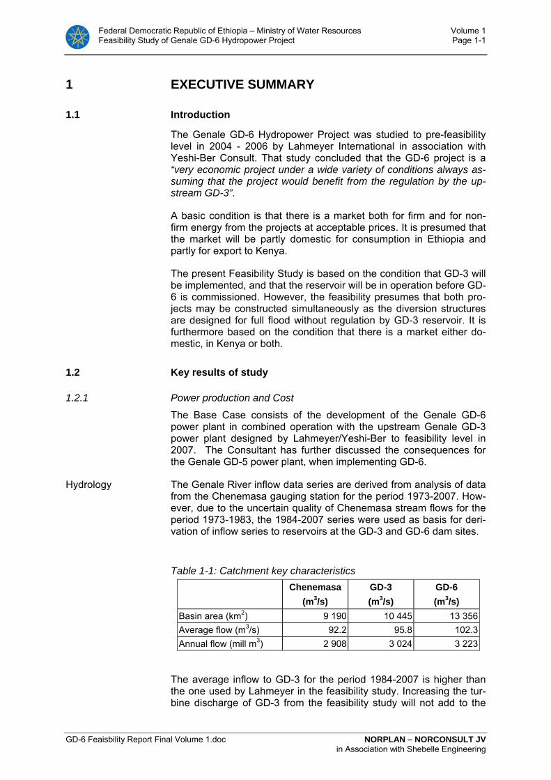
Hydrology The Genale River inflow data series are derived from analysis of data from the Chenemasa gauging station for the period 1973-2007. How-ever, due to the uncertain quality of Chenemasa stream flows for the period 1973-1983, the 1984-2007 series were used as basis for deri-vation of inflow series to reservoirs at the GD-3 and GD-6 dam sites.
Table 1-1: Catchment key characteristics
Chenemasa
(m3/s) GD-3 (m3/s)
GD-6 (m3/s)
Basin area (km2) 9 190 10 445 13 356Average flow (m3/s) 92.2 95.8 102.3Annual flow (mill m3) 2 908 3 024 3 223
The average inflow to GD-3 for the period 1984-2007 is higher than the one used by Lahmeyer in the feasibility study. Increasing the tur-bine discharge of GD-3 from the feasibility study will not add to the

Federal Democratic Republic of Ethiopia – Ministry of Water Resources Volume 1 Feasibility Study of Genale GD-6 Hydropower Project Page 1-2
GD-6 Feaisbility Report Final Volume 1.doc NORPLAN – NORCONSULT JV in Association with Shebelle Engineering
firm energy output, but would add slightly to the secondary energy output of the project.
GD-3 The key characteristics of the GD3 power plant are given in the table below.
Table 1-2: Key characteristics of GD-3
Reservoir FSL MOL Volume
1120 masl 1080 masl
2344 million m3
Average inflow 95.8 m3/s
Average turbine outflow 83.9 m3/s
Maximum turbine discharge 116.0 m3/s
Turbine number and type 3 x Francis
Installed capacity 254 MW
Average energy 2) 1640 GWh/year
Firm energy 1600 GWh/year 1) Hydrology series 1984-2004 2) Lahmeyer simulation.
GD-6 The regulated flow from GD-3 results in an almost firm inflow to GD-6. The selected turbine discharge is 120 m3/s giving an installed capac-ity of 246 MW, and a powerplant factor of 0.73.
Selection of GD-6 reservoir characteristics are based on simulations of energy output for different full and minimum operation levels. The simulations show that the reservoir requirement at GD-6 is limited and a regulation height of 5 m is selected. The project characteristics of the GD-6 power plant are summarised below.
Table 1-3: Key characteristics of GD-6
Reservoir FSL MOL Volume
585 masl 580 masl
39.3 million m3
Average inflow 1) 102,3 m3/s
Average turbine outflow 89.0 m3/s
Maximum turbine discharge 120.0 m3/s
Turbine number and type 2 x Francis
Installed capacity 246 MW
Average energy 2) 1 575 GWh/year
Firm energy 1 540 GWh/year
Total cost 469.8 mUSD For more details, see Section 1.4

Federal Democratic Republic of Ethiopia – Ministry of Water Resources Volume 1 Feasibility Study of Genale GD-6 Hydropower Project Page 1-3
GD-6 Feaisbility Report Final Volume 1.doc NORPLAN – NORCONSULT JV in Association with Shebelle Engineering
Energy Based on the optimisation analysis, a discharge capacity of 120 m3/s has been recommended, resulting in plant factor of 0.73. Firm energy is defined to be energy supplied with 95% reliability. The contribution of the two plants GD-3 and GD-6 to firm and total annual energy is shown in Table 9-13.
Table 1-4: Energy output data for GD-3 and GD-6
HEPP Firm energy [GWh/year]
Average energy [GWh/year]
Average deficit [GWh/year]
GD-3 3140
1725 1) 48.0
GD-6 1575 1)The power simulations by nMAG 2004 gives higher secondary energy for the GD-3 power plant, than calculated by Lahmeyer.
GD-5 For the purpose of checking the consequences of including GD-5 in optimisation of the Genale cascade of power plants, a preliminary reservoir curve and cost estimate were made for GD-5. Expecting a FSL at 690 and a tail water level of 585 (GD-6 FSL) will add about 655 GWh/y firm energy to the cascade. The preliminary cost estimate adds up to be 320 mill USD.
The preliminary optimisation clearly demonstrates that the option will lower the FSL of GD-5 by 10-15 m, and it is strongly recommended to study this further before concluding on the design of GD-6.
Cost The total cost for the GD-6 power plant is estimated at 469.8 MUSD. The cost for civil, electromechanical and transmission works are de-rived from prices experienced in other similar projects. The costs are summarised below, and more details are given in Chapter 11.
Table 1-5: Cost summary Item Total cost (mill USD) Infrastructure 49 147 Reservoir cost 935 Dam 109 325 Intake 5 434 Waterway 122 947 Power station 20 299 Power station equipment 88 261 Small Hydropower Plant 2 200 Transmission, switchyard, Local supply 26 530
Environmental cost 2 200 Engineering, supervision and Owners administration 42 508
Total cost 469 780

Federal Democratic Republic of Ethiopia – Ministry of Water Resources Volume 1 Feasibility Study of Genale GD-6 Hydropower Project Page 1-4
GD-6 Feaisbility Report Final Volume 1.doc NORPLAN – NORCONSULT JV in Association with Shebelle Engineering
1.2.2 Base Case, Economic and Financial analysis.
The economic energy cost (unit generation cost) delivered at Sodo Substation, which is assumed to be the connection point to ICS and export to Kenya for the Genale Cascade projects (GD-3, GD-5 and GD-6) is calculated at near at 4.43 UScent/kWh. This includes tech-nical transmission loss and relative cost-sharing of the transmission line to Sodo. It is further based on the estimated costs and implemen-tation schedule over 5 years for the power station and 40 years of operation horizon thereafter, including annual operation and mainte-nance cost of 0.8% of the investment cost and 0.2 UScent/kWh pro-duced. The economic analysis is based on a real discount rate of 10.23% as recommended by the Ministry of Finance and economic development (MoFED).
In parallel with this feasibility study for the GD-6 project a feasibility study for the Interconnection Project to Kenya has just been finalized. (Study made by the German consultant Fichtner GmbH with EEPCo and the Kenyan Ministry of Energy as clients.). Several options and cases for interconnection and export to Kenya were studied, giving different results of costs and values for export to Kenya. In connec-tion with this feasibility study for GD-6 the Consultant has calculated the average of the results from the Interconnection Study and applied these results as assumptions in the economic and financial analysis of the GD-6 project. On this basis it is assumed an expected average power value for export to Kenya at 5.16 USc/kWh at Sodo substation, giving the GD-6 project an economic margin of 0.77 USc/kWh.
The bulk tariff to Kenya is calculated as an average of the gap be-tween Kenya’s willingness to pay for the power referred Sodo (which is higher than the average price), and EEPCo’ minimum requirement for export (which is lower than the average price). Thus, this ar-rangement would give a win-win situation for both countries, making it a realistic option.
EEPCo’s minimum requirement tariff for export is assumed to be the marginal value of power in the ICS, thus making the sales price for power from GD-6 sold internally in Ethiopia. This price is estimated to be only 4.21 UScent/kWh, which would not cover the unit generation cost of 4.43 USc/kWh from the Project referred Sodo substation. This is an indication that the project may not be economic feasible for in-ternal power demand coverage only, and that export to Kenya should be the major purpose of the project. However, given this goal, the project is solid towards all the sensitivity analyses done.
It may be argued that covering internal demand has first priority, but EEPCOo has many projects in the pipeline and a large generation surplus is expected from about 2012 when Gilgel Gibe III is planned to be commissioned.
Given the major objective of selling power to Kenya (where power production is thermal based), the project could be a candidate for ob-taining CDM certificate (Clean Development Mechanism) and thus collect income from selling avoided CO2 quota (Carbone Emission Reduction, CERs). The value of this has not been included in the

Federal Democratic Republic of Ethiopia – Ministry of Water Resources Volume 1 Feasibility Study of Genale GD-6 Hydropower Project Page 1-5
GD-6 Feaisbility Report Final Volume 1.doc NORPLAN – NORCONSULT JV in Association with Shebelle Engineering
base case above, but has been analysed in one of the sensitivity op-tions.
Of other benefits, the Project would employ some estimated 5,000 man-years of local unskilled and semi-skilled labour during the con-struction phase. Though not included in the TOR, the Consultant has analysed as an option, a fee of respectively 1.0% and 5.0% of the yearly revenues from the project to be allocated for local develop-ment, since the project in itself does not give any benefits for the local community beyond the investment phase. The amount (respectively USD 0.8 and USD 4.0 mill per year) would allow the community to maintain roads, houses, various services and other infrastructure fa-cilities that will be developed during the construction phase, and even develop the area further.
As an export project, it would also give Ethiopia income of foreign cur-rency.
The benefit of local employment by the project has been included in the economic analysis by applying a conversion factor of 0.63 on lo-cal costs, as recommended by MoFED. This reflects the economic value (shadow value) of applying local labour.
The main economic results of the Base Case is shown in Table 1-6 where it is assumed that all power is exported to Kenya. This gives a NPV of USD 56 million compared with an investment cost of USD 445 million (469 million before conversion factor),, giving a benefit-cost ra-tio of 1.2, and an economic internal rate of return of 12.1%. Thus, the project would be on the border feasible with a discount rate of 12%.
Table 1-6: Base Case Economic Analysis. Export to Kenya
Energy cost 4.43 US cent/kWh Annualized cost per kWh at ICS/Sodo Substation
NPV 56 USD mill. Net Present Value
EIRR 12.1% Economic Internal Rate of Return
Payback 24 years Payback period
B/C 1.2 Benefit - Cost ratio
In the Financial analysis the base case is taken as on-lending from the Ethiopian Government at a subsidized interest rate of 2%,, based on the assumption that Government can raise international loans at concessional terms (soft loans). A 20% equity is foreseen at full inter-est rate of 10%, and 80% of the capital required is assumed as loan. It is further assumed soft conditions like a grace period of 10 years af-ter project commissioning, however interest paid during construction, and maturity of 30 years after end of the grace period. The same tar-iffs as in the economic analysis are used at Sodo substation.
The main results of the Base Case of the Financial analysis are given in Table 1-7, which shows financial NPV of USD 852 million giving a
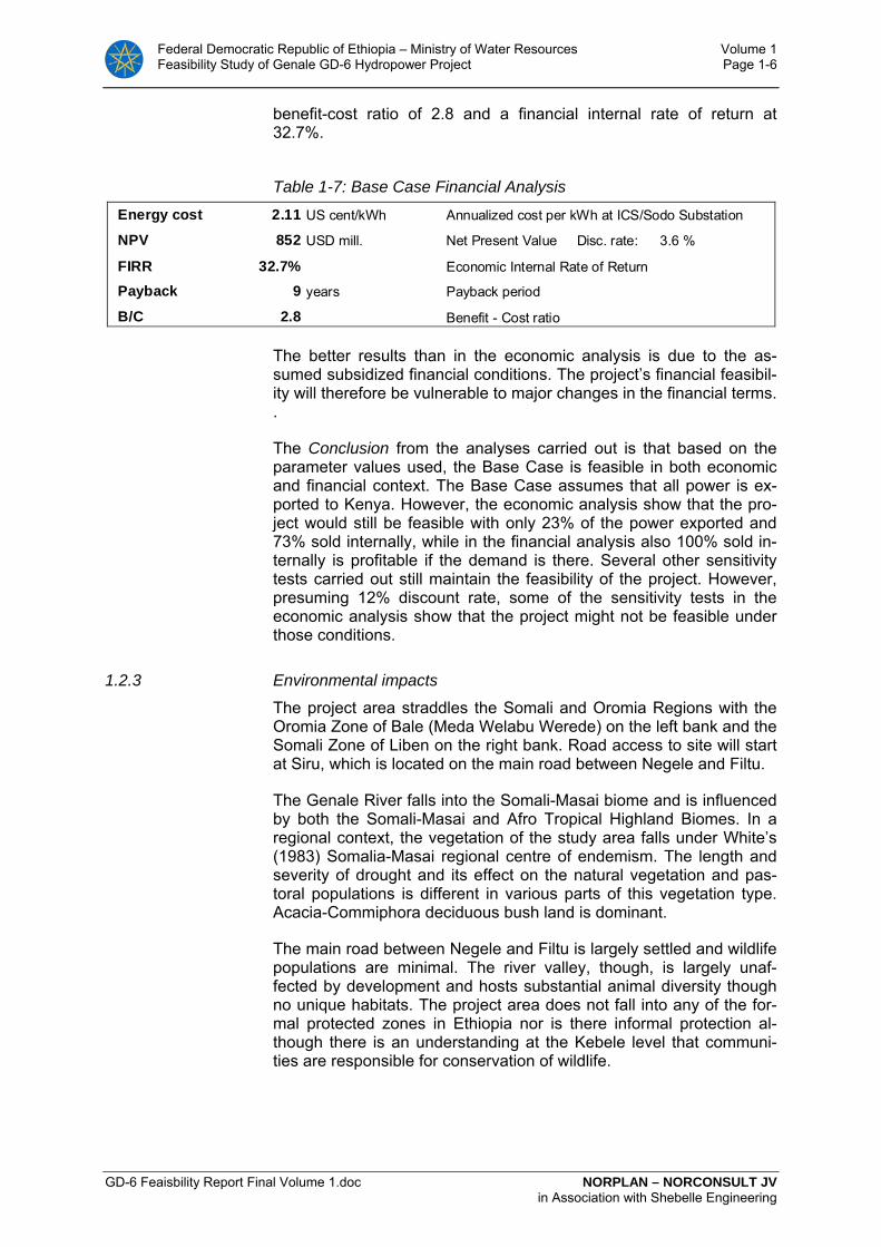
Federal Democratic Republic of Ethiopia – Ministry of Water Resources Volume 1 Feasibility Study of Genale GD-6 Hydropower Project Page 1-6
GD-6 Feaisbility Report Final Volume 1.doc NORPLAN – NORCONSULT JV in Association with Shebelle Engineering
benefit-cost ratio of 2.8 and a financial internal rate of return at 32.7%.
Table 1-7: Base Case Financial Analysis
Energy cost 2.11 US cent/kWh Annualized cost per kWh at ICS/Sodo Substation
NPV 852 USD mill. Net Present Value Disc. rate: 3.6 %
FIRR 32.7% Economic Internal Rate of Return
Payback 9 years Payback period
B/C 2.8 Benefit - Cost ratio
The better results than in the economic analysis is due to the as-sumed subsidized financial conditions. The project’s financial feasibil-ity will therefore be vulnerable to major changes in the financial terms. .
The Conclusion from the analyses carried out is that based on the parameter values used, the Base Case is feasible in both economic and financial context. The Base Case assumes that all power is ex-ported to Kenya. However, the economic analysis show that the pro-ject would still be feasible with only 23% of the power exported and 73% sold internally, while in the financial analysis also 100% sold in-ternally is profitable if the demand is there. Several other sensitivity tests carried out still maintain the feasibility of the project. However, presuming 12% discount rate, some of the sensitivity tests in the economic analysis show that the project might not be feasible under those conditions.
1.2.3 Environmental impacts
The project area straddles the Somali and Oromia Regions with the Oromia Zone of Bale (Meda Welabu Werede) on the left bank and the Somali Zone of Liben on the right bank. Road access to site will start at Siru, which is located on the main road between Negele and Filtu.
The Genale River falls into the Somali-Masai biome and is influenced by both the Somali-Masai and Afro Tropical Highland Biomes. In a regional context, the vegetation of the study area falls under White’s (1983) Somalia-Masai regional centre of endemism. The length and severity of drought and its effect on the natural vegetation and pas-toral populations is different in various parts of this vegetation type. Acacia-Commiphora deciduous bush land is dominant.
The main road between Negele and Filtu is largely settled and wildlife populations are minimal. The river valley, though, is largely unaf-fected by development and hosts substantial animal diversity though no unique habitats. The project area does not fall into any of the for-mal protected zones in Ethiopia nor is there informal protection al-though there is an understanding at the Kebele level that communi-ties are responsible for conservation of wildlife.
Federal Democratic Republic of Ethiopia – Ministry of Water Resources Volume 1 Feasibility Study of Genale GD-6 Hydropower Project Page 1-7
GD-6 Feaisbility Report Final Volume 1.doc NORPLAN – NORCONSULT JV in Association with Shebelle Engineering
There are two Kebeles (of the Liben Werede) that are affected by the project (by flooding of the reservoir and reduced flows in the section between the dam wall and the tailrace outlet), these are
1. Siru (upstream of the dam wall), and
2. Haydimtu (mainly in the area below the dam wall).
In general land use activities of the direct impact zone along the Genale River relate to response to drought conditions in which graz-ing and water resources in the Dawa River area are depleted. Both Kebeles focus their arable agriculture and pastoralism around the Dawa River to the south.
The amount of potential grazing lost through flooding of the reservoir will be about 818 ha. Although the reservoir will not reduce access to water, it will mean the loss of approximately 19 ha of riparian wood-land grazing on the right bank. Livestock do not make much use of the islands within the river due to the presence of crocodile.
There is no commercial fishery on Genale River in the vicinity of the dam site. However, some individuals catch fish for household pur-poses and for small scale trading at nearby towns.
There is no permanent settlement in the reservoir area or along the transmission line route to the GD-3 sub-station and no resettlement requirements attached to the project. No roads or other public infra-structure is located within the direct impact zone of the project. A few (22) temporary/seasonal pastoralist camps exist in the reservoir area but access to water will not be lost should the project be imple-mented.
Virtually all major impacts are associated with the influx of labour and the provision of road access to the area during the construction phase. Although there are no communities in the immediate vicinity of the project, any development will cause secondary impacts in the wider area in terms of socio-economic changes during the construc-tion period. Additional pressure on the riverine habitat downstream of the project may be anticipated through improved access also.
Assuming regulation of the Genale River by the upstream GD-3 res-ervoir then the incremental effects on the flow regime of adding the GD-6 to the cascade are minimal. No especially unique habitats fall within the reservoir area and, apart from the narrow belt of riverine vegetation, biomass is low and the area is used mostly for occasional grazing with very small patches (10ha) of recession type agriculture. Internationally, although the regulation provided by GD-3 and, to a very marginal extent GD-6, is likely to be beneficial to Somalia; it is doubtful that Somalia will have a government that is able to take ad-vantage in the near future.
The limited impact profile of the GD-6 project results in environmental costs not being high. Overall, with effective environmental manage-ment planning and an efficient monitoring regime any negative im-pacts should be capable of being controlled to acceptable levels.

Federal Democratic Republic of Ethiopia – Ministry of Water Resources Volume 1 Feasibility Study of Genale GD-6 Hydropower Project Page 1-8
GD-6 Feaisbility Report Final Volume 1.doc NORPLAN – NORCONSULT JV in Association with Shebelle Engineering
1.3 Genale GD-6 - Brief description of the recommended project
Project drawing B01
1.3.1 Project location
The Genale GD-6 Hydropwer project is located on the Genale River of the Genale Dawa River basin, approximately 80 km east of Negele, in Liben Zone of the Somali National Regional State. The project area is approximately 700 km by road south and east of Addis Ababa. The project forms the downstream power plant in a series of three utilising the large reservoir of the planned hydropower project GD-3 located some 82 km further upstream along the Genale River. Just upstream of the reservoir of GD-6 is a potential Hydropower Project GD-5, which forms the middle hydropower project in the series. The location of the projects are shown in Figure 1-1 below.
The project GD-6 exploits the head over an approximately 31 km stretch of the river with a maximum gross head of 234 m between the elevations 585 masl and 351 masl.
Figure 1-1: Location of the Genale Hydropower Projects GD-3, GD-5 and GD-6

Federal Democratic Republic of Ethiopia – Ministry of Water Resources Volume 1 Feasibility Study of Genale GD-6 Hydropower Project Page 1-9
GD-6 Feaisbility Report Final Volume 1.doc NORPLAN – NORCONSULT JV in Association with Shebelle Engineering
1.3.2 Civil structures and reservoir
The dam of Genale GD-6 with a crest length of around 650 m and a maximum height of 60 m above ground is presented as an asphaltic concrete core Rock fill dam (ACCRD). The options of concrete faced Rock fill dam (CFRD) and the roller compacted RCC dam should be further studied in the final/tender design stage.
The selected dam site (FS-2) is the downstream option of two poten-tial dam sites. The upstream option (dam site FS-1) seems to be more favourable from a topographic point of view. However, the ground conditions at the left abutment of a potential dam at this site might require an expensive cut-off structure. Based on the present knowledge of the geotechnical conditions, a dam structure at the FS-1 site could imply a total dam cost significantly higher than the cost of the dam at the selected site FS-2. On the other hand, if the ground condition at the left bank would prove more favourable than the pres-ently available information would indicate, the total dam cost could be less. It is recommended to carry out further geotechnical investiga-tions at FS-1 as basis for the final design. Shifting the dam from site FS-2 to FS-1 would not have any influence on the rest of the project. Intake, waterway, and reservoir water levels would remain the same as designed.
The dam creates a reservoir with a gross volume of 181 mill m3. The active volume between highest regulated water level 585 and lowest regulated water level 580 is 39.3 mill m3.
The topography at the dam site is steep, and a side channel spillway with a chute is found to be the optimum solution for diverting floods at the site.
The power intake is located as a separate structure on the right side of the river, some 900 m south of the dam. From here a 4.7 km long circular pressure headrace tunnel of 63.6 m2 cross section (dia=9 m) will convey the water to the powerhouse cavern. Geological condi-tions are such that the pressure tunnel will be unlined, with the excep-tion of two 40 m long steel lined penstocks.
A 120 m long vertical shaft connects the headrace tunnel to the surge chamber. The surge facilities are located 850 m upstream of the powerhouse.
The powerhouse will be equipped with two vertical Francis units, to-talling 250 MW. The powerhouse is located in a ridge on the right river bank, which offers favourable geological conditions for the pow-erhouse and transformer caverns and all other appurtenant struc-tures.
A major surge chamber is needed on the tailrace, and a 4000 m2 chamber is established by widening the tailrace tunnel for the first 330 m downstream of the draft tubes. The surge chamber (tunnel) will have a cross section of 380 m2. From the surge chamber the tur-bine flow is conveyed through a Ø 9 m TBM drilled, 11,7 km long tun-nel to the tailrace outlet.

Federal Democratic Republic of Ethiopia – Ministry of Water Resources Volume 1 Feasibility Study of Genale GD-6 Hydropower Project Page 1-10
GD-6 Feaisbility Report Final Volume 1.doc NORPLAN – NORCONSULT JV in Association with Shebelle Engineering
1.3.3 Electromechanical equipment
Mechanical equipment
Based on the design head and turbine flow, vertical Francis turbines represent the only practical solution for Genale GD-6.
Two units are foreseen. In the case of Genale GD6, the flow duration curve does not favour the use of three units relative to two. The in-crease in generation is calculated to be only 2GWh. This additional generation does not justify for the increased cost of three units.
The level in the intake reservoir will vary between 585 masl at Full Storage Level (FSL) and 580 masl at Minimum Operation Level (MOL). The normal operation level should be close to 585, and with a tail water level at el. 351, the gross design head for the turbines is set to 234 m. Total output for the two turbines will then be 250 MW.
The governors are conventional electro-hydraulic governors, permit-ting all normal operation modes. The oil pressure system includes ni-trogen type accumulators giving necessary safety to shut down the units in an emergency condition.
The powerhouse crane will be a bridge crane with a main hoist, which will serve any requirements for lifting and moving of heavy components during installation, maintenance work and operation. The crane will be provided with an auxiliary hoist travelling under one of the crane girders.
Steel lining will be installed only for the headrace section immediately upstream of the powerhouse. Two steel penstocks are leading to the turbines via spherical valves.
Detailed description and data tables for turbines, valves, gates, trash racks, steel penstock and bulkheads are given in Chapter 3.8
Generators
The 150 MVA generators will be vertical shaft, salient poles, synchro-nous generators directly coupled to the Francis turbines.
The generator rated output corresponds to the turbine power at de-sign head and a power factor (PF or cos φ) of 0.86, which will give the generators sufficient capacity for reactive power to support the normal requirements of the transmission grid.
Rated generator voltage should be left to the supplier to optimise, but it will most likely be in the range of 12-16 kV.
Transformers
The 150 MVA, 420/Ug (Ug=transformer voltage) transformers will be located in a separate cavern shortly downstream of the main power-house cavern.
Detailed description and data for electrical equipment for Genale GD-6 are given in Chapter 3.10.
Federal Democratic Republic of Ethiopia – Ministry of Water Resources Volume 1 Feasibility Study of Genale GD-6 Hydropower Project Page 1-11
GD-6 Feaisbility Report Final Volume 1.doc NORPLAN – NORCONSULT JV in Association with Shebelle Engineering
Switchyard/Transmission
The switchyard will be located outdoors. The cables will be placed in a separate cable tunnel with outlet 200 m west of the switchyard. A single circuit 400 kV AC line, 75 km long, will be constructed from Genale GD-6 to GD-3 substation. The transmission line will pass near the proposed GD-5 power plant location.
Detailed description of the power system and transmission lines is given in Chapter 4.
1.3.4 Small Hydropower Plant
A bypass for release of a minimum flow of 2.5 m3/s has been ar-ranged in the diversion culvert. The Consultant suggests installing a small hydro unit to generate power from the compensation water re-lease downstream of the dam. The turbine will be a standard compact unit with horizontal shaft, with a load controller to ensure correct wa-ter release at all times.
The installed capacity will be 1.35 MW, and as it should be operated 365 days/year, the yearly energy output will be 11.8 GWh. The unit will be connected to the 33 kV transmission line and supply power into the Negele substation.

Federal Democratic Republic of Ethiopia – Ministry of Water Resources Volume 1 Feasibility Study of Genale GD-6 Hydropower Project Page 1-12
GD-6 Feaisbility Report Final Volume 1.doc NORPLAN – NORCONSULT JV in Association with Shebelle Engineering
1.4 Key project characteristics for Genale GD-6
Table 1-8: Key data of the Genale GD-6 Project - Base Case Power and Energy Total rated output from 2 units 246 MW Mean annual energy generation 1 575 GWh/a Firm annual energy 1 475 GWh/a Plant factor 0.73 % Design discharge, total for 2 units 120 m3/s Maximum gross head 234 m Minimum gross head 229 m Type of transmission line to GD-3 400 kV AC, single c. Length of transmission line to GD-3 75 km Hydrologic Data Genale River catchment area upstream of Genale GD-6 dam 13 356 km2
Mean river flow at Genale GD-6 dam site 102.3 m³/s
20-year flood (natural inflow) 950-1150 m³/s
100-year flood (natural inflow) 1300-1700 m³/s
1000-year flood (routed inflow) 1 150 m³/s PMF (routed inflow) 2 500 m³/s Reservoir Full Supply Level (FSL) 585 masl Minimum Operation Level (MOL) 580 masl Total volume at FSL 181 Mm³ Active reservoir volume 39.3 Mm³ Surface at FSL 8 km² Extension of reservoir towards upstream at FSL 12 km Main Dam Type of dam Asphalt concrete core Rock fill dam (ACCRD) Dam crest elevation 591.5 masl Maximum height of dam above foundation 60 m Crest length of dam 650 m Dam volume 1.5 Mill m³ Spillway Type Concrete gravity with free overfall and chute Elevation of overfall crest 585.0 masl Length of spillway crest 100 m PMF outflow 2 500 m3/s Reservoir elevation at PMF outflow 590.2 masl Spillway capacity at reservoir level 1525 masl 2500 m³/s Power Intake Elevation of intake sill 566.0 masl Type and number of intake gates roller gates, 1 nos Intake gate dimensions (w x h) 5.5 x 8.2 m Trash rack dimensions (w x h) 10.0 m x 12.0 m Sediment flushing NA Headrace Tunnel Tunnel dimension D=9 m 63.6 m2
Tunnel length intake to penstock 4700 m
Penstock Diameter of penstock 2 x 4.2 m Length 45 m
Powerhouse Type of powerhouse Underground Powerhouse cavern dimensions (l x w x h) 65x17x39 m Elevation of machine hall floor 360.2 masl Cross section of access tunnel 50 m2 Length of access tunnel 1150 m Elevation of turbine centre 347.7 masl Tailrace Tunnel Tunnel dimension D=9 m 63.6 m2 Tunnel length from draft tube outlet to river outlet 11 700 m Dimensions of draft tube gates (w x h) 4.25 x 7.1 m Elevation of tailrace outlet sill 342.5 masl Turbines/Generators Type of turbine (2 units) Vertical Francis Design discharge, per unit 60 m³/s Total rated output at design net head, 2 units 125.4 MW Maximum output 129.1 MW Synchronous speed 300 rpm Generator nominal active rating per unit 129 MW Generator nominal apparent power per unit (cosφ = 0.86) 150 MVA Maximum runaway speed 480 rpm Transformers Type and number of transformers Three-phase, 2 nos Maximum voltage 420/17.5 Nominal power per transformer 150 Transformer cell dimensions (l x w x h) 11 x 7 x 6.8
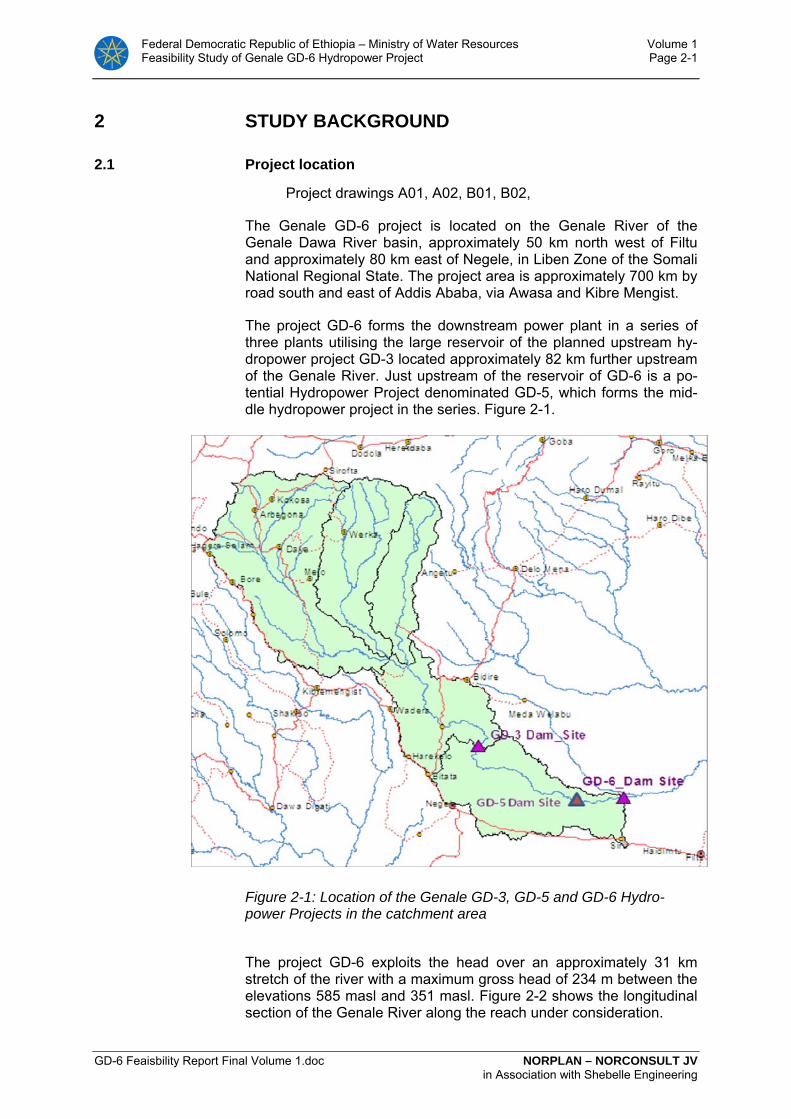
Federal Democratic Republic of Ethiopia – Ministry of Water Resources Volume 1 Feasibility Study of Genale GD-6 Hydropower Project Page 2-1
GD-6 Feaisbility Report Final Volume 1.doc NORPLAN – NORCONSULT JV in Association with Shebelle Engineering
2 STUDY BACKGROUND
2.1 Project location
Project drawings A01, A02, B01, B02,
The Genale GD-6 project is located on the Genale River of the Genale Dawa River basin, approximately 50 km north west of Filtu and approximately 80 km east of Negele, in Liben Zone of the Somali National Regional State. The project area is approximately 700 km by road south and east of Addis Ababa, via Awasa and Kibre Mengist.
The project GD-6 forms the downstream power plant in a series of three plants utilising the large reservoir of the planned upstream hy-dropower project GD-3 located approximately 82 km further upstream of the Genale River. Just upstream of the reservoir of GD-6 is a po-tential Hydropower Project denominated GD-5, which forms the mid-dle hydropower project in the series. Figure 2-1.
Figure 2-1: Location of the Genale GD-3, GD-5 and GD-6 Hydro-power Projects in the catchment area
The project GD-6 exploits the head over an approximately 31 km stretch of the river with a maximum gross head of 234 m between the elevations 585 masl and 351 masl. Figure 2-2 shows the longitudinal section of the Genale River along the reach under consideration.
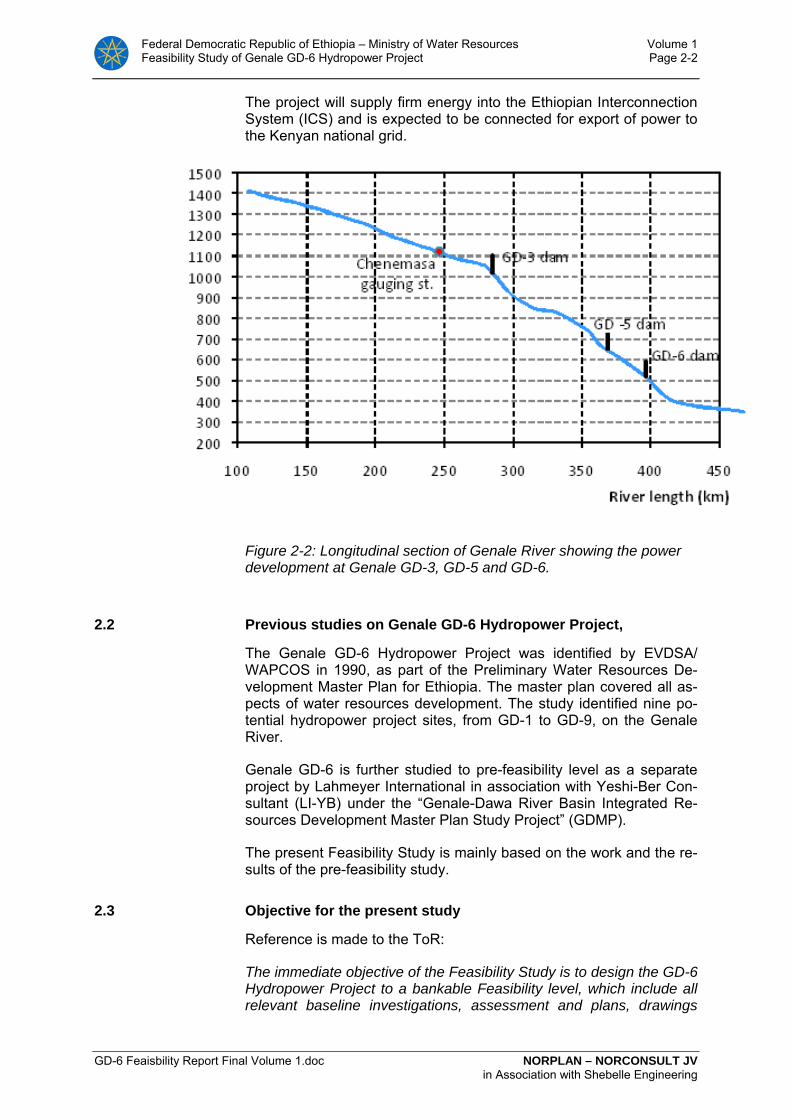
Federal Democratic Republic of Ethiopia – Ministry of Water Resources Volume 1 Feasibility Study of Genale GD-6 Hydropower Project Page 2-2
GD-6 Feaisbility Report Final Volume 1.doc NORPLAN – NORCONSULT JV in Association with Shebelle Engineering
The project will supply firm energy into the Ethiopian Interconnection System (ICS) and is expected to be connected for export of power to the Kenyan national grid.
Figure 2-2: Longitudinal section of Genale River showing the power development at Genale GD-3, GD-5 and GD-6.
2.2 Previous studies on Genale GD-6 Hydropower Project,
The Genale GD-6 Hydropower Project was identified by EVDSA/ WAPCOS in 1990, as part of the Preliminary Water Resources De-velopment Master Plan for Ethiopia. The master plan covered all as-pects of water resources development. The study identified nine po-tential hydropower project sites, from GD-1 to GD-9, on the Genale River.
Genale GD-6 is further studied to pre-feasibility level as a separate project by Lahmeyer International in association with Yeshi-Ber Con-sultant (LI-YB) under the “Genale-Dawa River Basin Integrated Re-sources Development Master Plan Study Project” (GDMP).
The present Feasibility Study is mainly based on the work and the re-sults of the pre-feasibility study.
2.3 Objective for the present study
Reference is made to the ToR:
The immediate objective of the Feasibility Study is to design the GD-6 Hydropower Project to a bankable Feasibility level, which include all relevant baseline investigations, assessment and plans, drawings

Federal Democratic Republic of Ethiopia – Ministry of Water Resources Volume 1 Feasibility Study of Genale GD-6 Hydropower Project Page 2-3
GD-6 Feasibility Report Final Volume 1.doc NORPLAN – NORCONSULT JV in Association with Shebelle Engineering
and cost estimates regarding technical, economic/financial, environ-mental, and socio-economic aspects. The ultimate objective of the study is to increase the energy and power generation capability of the country and to obtain a reliable and adequate supply of electric en-ergy, and sustain economic development.
The study will analyse and document all important aspects required for the formal approval of the Project by MoWR and other government authorities of Ethiopia.
.
.

Federal Democratic Republic of Ethiopia – Ministry of Water Resources Volume 1 Feasibility Study of Genale GD-6 Hydropower Project Page 3-1
GD-6 Feaisbility Report Final Volume 1.doc NORPLAN – NORCONSULT JV in Association with Shebelle Engineering
3 GENALE GD-6 – PROJECT DESCRIPTION
Project drawing B 01
3.1 Genale GD-6 - Arrangement of project structures Genale GD-6 is the most downstream one of the potential hydro-power schemes on Genale River. The dam of Genale GD-3 creates the head pond and storage reservoir for the cascade with a capacity sufficient for a significantly improved flow regulation.
The Genale-Dawa Master Plan, GD-6 Pre-feasibility study concludes with a feasible site for implementation of a power project at GD-6. The site appears favourable, for the following reasons:
• The GD-3 project regulates the flow in the Genale River and inflow to GD-6 is favourable for firm energy production.
• The site offers good rock conditions
• Several Dam site options with acceptable cross sections are iden-tified
• A head of about 235 m is achieved by a dam, 60 m high and rela-tively long tunnels, 16.5 km.
Figure 3-1: Overview of the Genale GD-6 project
An asphaltic concrete core Rock fill dam type (ACCRD) has been se-lected for feasibility design. It will have a length of 650 m and a maximum height of 60 m above ground.
The 100 m wide side channel spillway is constructed as a free over-flow on the right bank of the river. From the side channel a chute takes the flow down to the river.
From the power intake, located 900 m south of the dam, a 4.8 km long pressurised headrace tunnel conveys the water to the power-

Federal Democratic Republic of Ethiopia – Ministry of Water Resources Volume 1 Feasibility Study of Genale GD-6 Hydropower Project Page 3-2
GD-6 Feaisbility Report Final Volume 1.doc NORPLAN – NORCONSULT JV in Association with Shebelle Engineering
house cavern via a 25 m long lined penstock. A 12 km long tailrace tunnel leads to the Tail water. Both headrace and tailrace need surge facilities.
3.2 Genale GD-6. Layout changes.
The general layout of the Genale GD-6 project is changed from the Pre-feasibility study by Lahmeyer. The major changes are:
- Shifting of the powerhouse from an open air downstream location, to an underground location 12 km upstream, hereby
- Reducing the length of pressure tunnel from 15 km to 4,8 km.
- Replacing 12 km headrace tunnel with tailrace tunnel.
- Avoiding steel lining of an up to 300 m long part of the headrace tunnel.
- Avoiding 1100 m steel penstock.
- Needing additional surge chamber on the tailrace
- Reducing risk for tunnel excavation in the sediment rock.
Dam is shifted downstream, but no principal changes made.
The brief estimate, without trying to calculate cost for rock support, is compared in Table 3-1 below:
Table 3-1: Rough cost comparison between proposed Pre- feasibility design and Feasibility design.
Pre-feasibility design Feasibility design
Steel lining, 300 m 12-15 mill NIL
Steel penstock 38 mill 8 mill
Surge chamber 14 mill 18 mill
Power station, access NIL 8-10 mill
The estimated prices of the Pre-feasibility study is taken from the Pre-feasibility report. The major difference in cost is related to steel lining and steel penstock. The Pre-feasibility cost is not adjusted for general cost increase since presentation of the report.
An alternative layout with an underground power station located at the downstream end of the tunnel (1-2 km upstream of outlet) would re-duce the penstock cost, but the steel lining and surge chamber cost from the Pre-feasibility study will remain unchanged.

Federal Democratic Republic of Ethiopia – Ministry of Water Resources Volume 1 Feasibility Study of Genale GD-6 Hydropower Project Page 3-3
GD-6 Feaisbility Report Final Volume 1.doc NORPLAN – NORCONSULT JV in Association with Shebelle Engineering
In the Consultants opinion the change of project layout has reduced the cost by some 30-40 mill USD based on the cost level used in the Feasibility study.
3.3 Genale GD-6 - Dam and reservoir
Project drawings B03 to B09
3.3.1 Dam axis selection
The maps produced for the present study show that the narrowest valley profile is the one dam site named FS-1. However due to geo-logical conditions the dam site was shifted to FS-2 during the design.
Both dam sites have generally favourable topographic conditions with the hills rising more than 50 m above the considered crest levels.
Several dam sites further downstream were considered, but all op-tions increases the dam volume to an unacceptable level.
The dam axis’s is defined by the following co-ordinates:
Table 3-2: Coordinates proposed dam axis
FS-1 FS-2 Left Bank North 594 355 North 595 065
East 646 505 East 647 380 Right Bank North 594 100 North 594 550
East 647 130 East 647 475

Federal Democratic Republic of Ethiopia – Ministry of Water Resources Volume 1 Feasibility Study of Genale GD-6 Hydropower Project Page 3-4
GD-6 Feaisbility Report Final Volume 1.doc NORPLAN – NORCONSULT JV in Association with Shebelle Engineering
Figure 3-1: Location of Genale GD-6 main dam site options
3.3.2 Dam height
Figure 3-2: Dam volume of studied dam sites.
The analysis leading to the selected dam height is summarised as follows:

Federal Democratic Republic of Ethiopia – Ministry of Water Resources Volume 1 Feasibility Study of Genale GD-6 Hydropower Project Page 3-5
GD-6 Feaisbility Report Final Volume 1.doc NORPLAN – NORCONSULT JV in Association with Shebelle Engineering
• An optimisation analysis has been made (ref. Annex 3 C, Chap-ter 5), demonstrating that it is beneficial to increase reservoir level above the elevation recommended in this study (585 masl). However, increasing it further reduces the available head and feasibility of the upstream potential HEPP site, GD-5.
• The topographical conditions are favourable above the selected elevation, but rock conditions for the dam foundation are poor above el. 570-575 masl, and hence, increasing the FSL further would imply major cost for dam foundation preparation.
• The reservoir operation studies (see Chapter 9, and Annex 3 C) shows that the Firm energy potential of the cascade development of GD-3, GD-5 and GD-6 will be fully utilised even with a lower dam than selected.
• The reservoir operation studies (see Chapter 9, and Annex 3 A) also shows that the Firm energy potential of the cascade devel-opment of either GD-3, GD-5 and GD-6, or GD-3 and GD-6 does not require a major reservoir at GD-6 to utilise the energy poten-tial of the site.
• Excavation of up to 2 m soil, and 2 m rock in the dam foundation has been included in the calculations.
• Increasing the FSL of GD-6 decreases the tunnel lengths of GD-5 HEPP, by an average of 110 m for each 1 m of increase of GD-6 FSL. The value of reduced tunnel length is included in optimi-sation when considering the option of the cascade GD-3. GD-5 and GD-6.
• The spillway is a free, non-gated side overflow with crest eleva-tion 585 masl, corresponding to FSL. From the spillway a side channel and a chute leads the water down to the river.
• Two calculations for PMF are presented. The worst case sce-nario gives a PMF of 2665 m3/s corresponding to a FWL (flood water level) of 590.5.
• Considering the necessary surcharge height for the design flood discharge and sufficient allowance for a freeboard, a crest eleva-tion of 7.0 m above FSL has been selected.
The crest elevation for the structures (main dam and intake) was thus fixed at 585.00 masl.
The 5 m contour digital map shows a minimum ground level of 520-525 masl along the dam axis. With a crest level on 591.5 masl the maximum height of Genale GD-6 dam would thus be 65 m above ground.
3.3.3 Dam type and sealing concept
Project drawings B04
Reference Reference is made to Chapter 7 and to Volume 4 of the feasibility re-port, for detailed descriptions of the ground conditions and design considerations regarding the dam and dam site options.

Federal Democratic Republic of Ethiopia – Ministry of Water Resources Volume 1 Feasibility Study of Genale GD-6 Hydropower Project Page 3-6
GD-6 Feaisbility Report Final Volume 1.doc NORPLAN – NORCONSULT JV in Association with Shebelle Engineering
Available materials Availability of suitable materials is one main criterion for selection of dam type. In the Genale GD-6 project area the rock is of very good quality, easily available close to the dam site at a location that will remain under lowest regulated water levels. The tunnels will also be excavated in rock type well suited for dam construction and for con-crete aggregates. Clayey or other types of natural materials suitable for use as low permeability core material are not available in sufficient quantities. The scarce deposits of clayey materials are decomposed from partly gypsiferous materials and are not suited for dam construc-tion because of its swelling and soluble properties. Consequently, an earth fill dam with clay core is out of question for GD-6 dam.
The dam should be constructed using rock materials, either as rock fill dam or as concrete dam.
Three different dam types have been evaluated for GD-6 dam:
• Roller Compacted Concrete Dam (RCCD)
• Concrete Faced Rock Fill Dam (CFRD)
• Asphaltic Concrete Core Rock Fill Dam (ACCRD)
Roller Compacted Concrete Dam (RCCD)
The RCC dam type has several advantages related to layout and to volume of construction materials. The type is furthermore not very sensitive to weather condition during construction.
A major advantage is that the dam crest may be used as spillway. The water diversion structures may be less comprehensive during construction, and the consequences of an accidental overtopping dur-ing construction are not as disastrous as for an embankment dam.
The disadvantages are the cost and the need of large quantities of cement and slag for cement replacements, which are not available in the area.
Concrete Faced Rock Fill Dam (CFRD)
Rock fill dams must contain an impervious zone. As no suitable clay materials are available in the area, one option is to construct a con-crete slab on the upstream slope of the dam. The concrete face has the advantage that it requires relatively small quantities of materials that need to be transported long distances. The only material not available locally is the cement for the relatively thin front concrete slab. At GD-6 the rock materials are of good quality suitable for dam construction. The cost are favourable.
A disadvantage is the need of spillway structure constructed at the side of the dam, or constructed as a separate concrete structure somewhere within the dam body.
Asphaltic Concrete Core Rock Fill Dam (ACCRD)
An alternative to use a concrete slab as upstream impervious zone in the rock fill dam is to construct an impervious central core of asphaltic

Federal Democratic Republic of Ethiopia – Ministry of Water Resources Volume 1 Feasibility Study of Genale GD-6 Hydropower Project Page 3-7
GD-6 Feaisbility Report Final Volume 1.doc NORPLAN – NORCONSULT JV in Association with Shebelle Engineering
concrete. Asphaltic concrete has a special mix of binder in an aggre-gate mix instead of cement. The core is impervious and flexible, which is of advantage with regard to settlements in the supporting rock fill.
Another advantage is that the construction method is less vulnerable to adverse weather conditions than the other dam types.
Selected dam type The cost estimates indicates that an asphaltic concrete core would be the most favourable dam type for GD-6. The Consultant has selected ACCRD as basis for the feasibility study. However, unit construction cost as well as cost of materials changes continuously. In connection with final design the cost estimates should be reviewed based on up-dated unit rates.
3.3.4 Reservoir features
The main reservoir in the Genale River is the GD-3 reservoir, about 100 km upstream of GD-5 dam site. The reservoir is designed as part of the GD-3 feasibility study by Lahmeyer International in association with Yeshi Ber Consult, The following reservoir data has been con-cluded:

Federal Democratic Republic of Ethiopia – Ministry of Water Resources Volume 1 Feasibility Study of Genale GD-6 Hydropower Project Page 3-8
GD-6 Feaisbility Report Final Volume 1.doc NORPLAN – NORCONSULT JV in Association with Shebelle Engineering
Table 3-3: Genale GD-3 reservoir, elevation-area and elevation-volume relationships
Elevation masl
Area km2
Volume mill m3
1020 0.0 0 1030 0.15 1 1040 0.47 4 1050 1.4 13 1060 2.8 34 1070 9.5 95 1080 23.0 260 LRWL 1090 39.0 570 1100 57.0 1040 1110 76.0 1710 1120 98.0 2570 HRWL 1130 119.0 3650 1140 142.0 4950
Figure 3-3: Genale GD-3 reservoir, elevation-area and elevation-volume curves.
The optimum regulation limits for the Genale GD-6 dam have been found by the power simulations presented in (Chapter 9). The follow-ing features of the reservoir is selected:
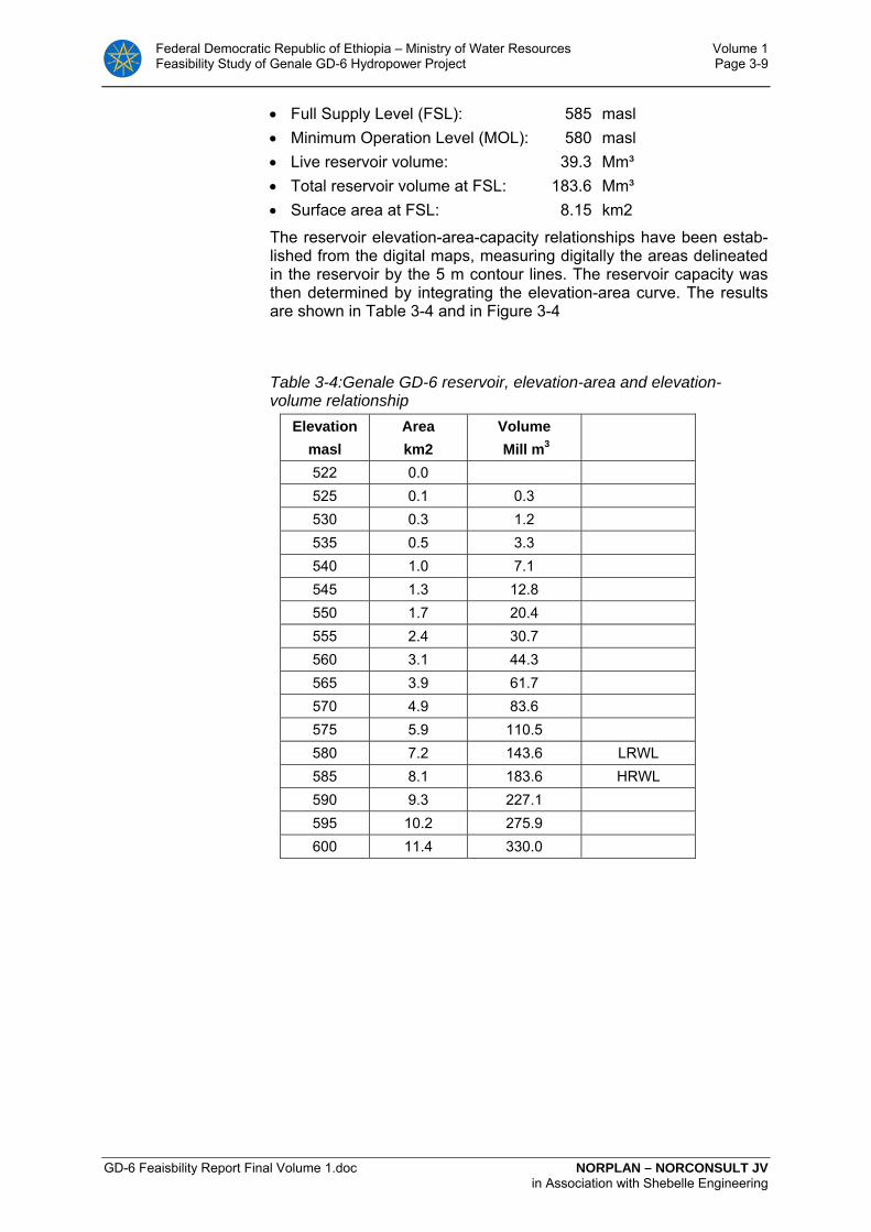
Federal Democratic Republic of Ethiopia – Ministry of Water Resources Volume 1 Feasibility Study of Genale GD-6 Hydropower Project Page 3-9
GD-6 Feaisbility Report Final Volume 1.doc NORPLAN – NORCONSULT JV in Association with Shebelle Engineering
• Full Supply Level (FSL): 585 masl • Minimum Operation Level (MOL): 580 masl • Live reservoir volume: 39.3 Mm³ • Total reservoir volume at FSL: 183.6 Mm³ • Surface area at FSL: 8.15 km2
The reservoir elevation-area-capacity relationships have been estab-lished from the digital maps, measuring digitally the areas delineated in the reservoir by the 5 m contour lines. The reservoir capacity was then determined by integrating the elevation-area curve. The results are shown in Table 3-4 and in Figure 3-4
Table 3-4:Genale GD-6 reservoir, elevation-area and elevation-volume relationship
Elevation masl
Area km2
Volume Mill m3
522 0.0 525 0.1 0.3 530 0.3 1.2 535 0.5 3.3 540 1.0 7.1 545 1.3 12.8 550 1.7 20.4 555 2.4 30.7 560 3.1 44.3 565 3.9 61.7 570 4.9 83.6 575 5.9 110.5 580 7.2 143.6 LRWL 585 8.1 183.6 HRWL 590 9.3 227.1 595 10.2 275.9 600 11.4 330.0

Federal Democratic Republic of Ethiopia – Ministry of Water Resources Volume 1 Feasibility Study of Genale GD-6 Hydropower Project Page 3-10
GD-6 Feaisbility Report Final Volume 1.doc NORPLAN – NORCONSULT JV in Association with Shebelle Engineering
Figure 3-4: Genale GD-6 reservoir, elevation-area and elevation-volume curves
At full supply level 585 masl the headwater of the reservoir extends more than 12 km upstream with a width of the reservoir of some 600 m near the dam site. 650 m will be the average width of the reservoir.
An ungated spillway with crest elevation at FSL, is proposed. Flood levels in the reservoir will then be higher than with gated spillways, but total cost and security for diverting floods makes ungated spill-ways feasible for GD-6. The spillway length is 100 m, and the related flood levels will be (worst case scenario calculation):
• 10-year flood level (850 m3/s): 587.60 masl (unregulated) • 100-year flood level (1500 m3/s): 588.65 masl (unregulated) • 1000-year flood level (1100 m3/s) 588.08 masl • PMF flood level (2590 m3/s): 589.35 masl
The 10 and 100-year inflow floods will normally be retained by the GD-3 reservoir. The calculated floods are therefore mainly from the local catchment only. The 1000-year and PMF floods are routed through the GD-3 reservoir.
The GD-6 reservoir area is rather small, compared to inflow floods, and the capacity of reducing the larger floods is limited.
Federal Democratic Republic of Ethiopia – Ministry of Water Resources Volume 1 Feasibility Study of Genale GD-6 Hydropower Project Page 3-11
GD-6 Feaisbility Report Final Volume 1.doc NORPLAN – NORCONSULT JV in Association with Shebelle Engineering
3.4 Genale GD-6 - Spillway
Project drawings B09 and B10
3.4.1 Spillway type and dimensions
The spillway is designed to withstand the PMF floods, but with limited freeboard and hence a limited safety.
Type The GD-6 spillway is planned to be at the right bank of the river. Based on topographical, geological and other factors mainly two types of spillway have been investigated in details as options. The two spillway types are:
• side channel spillway with chute option and
• side channel spillway with stepped spillway option.
For both considered options the following parts of spillway are com-mon:
• Control structure (weir in the form of ogee profile).
• Side channel (trench along the contours).
• Spill channel.
• Control weir at the end of the spill channel. Floods In determining the spillway type, the best combination of storage ca-
pacity and spillway flood capacity of GD-6 dam and reservoir, all per-tinent factors of hydrology, hydraulics design, cost, and damage due to possible dam breach have been considered. Considered spillway type, the maximum spillway discharge (Qmax), required spillway crest length (L) and the maximum reservoir water level (FSL) are as listed bellow:
Considered return period for design is PMF.
Design flood Qmax= Q(PMF) =2595 m3/sec.
Spillway crest length, L=100 m.
Reservoir Full Supply Level, FSL=585 masl.
Surcharge, H=5.35m.
Spillway components The topography of the abutments at the GD-6 dam site is a quite steep hillside. For such topographical condition, the first option of spillway structure is a side channel overflow spillway. The spillway has the following structural components:
a) Ogee profile overflow spillway (weir).
b) Side channel trough.
c) Spill-channel with sub critical slope.
d) Chute or stepped spillway and.
e) Energy dissipation structure (stilling basin).
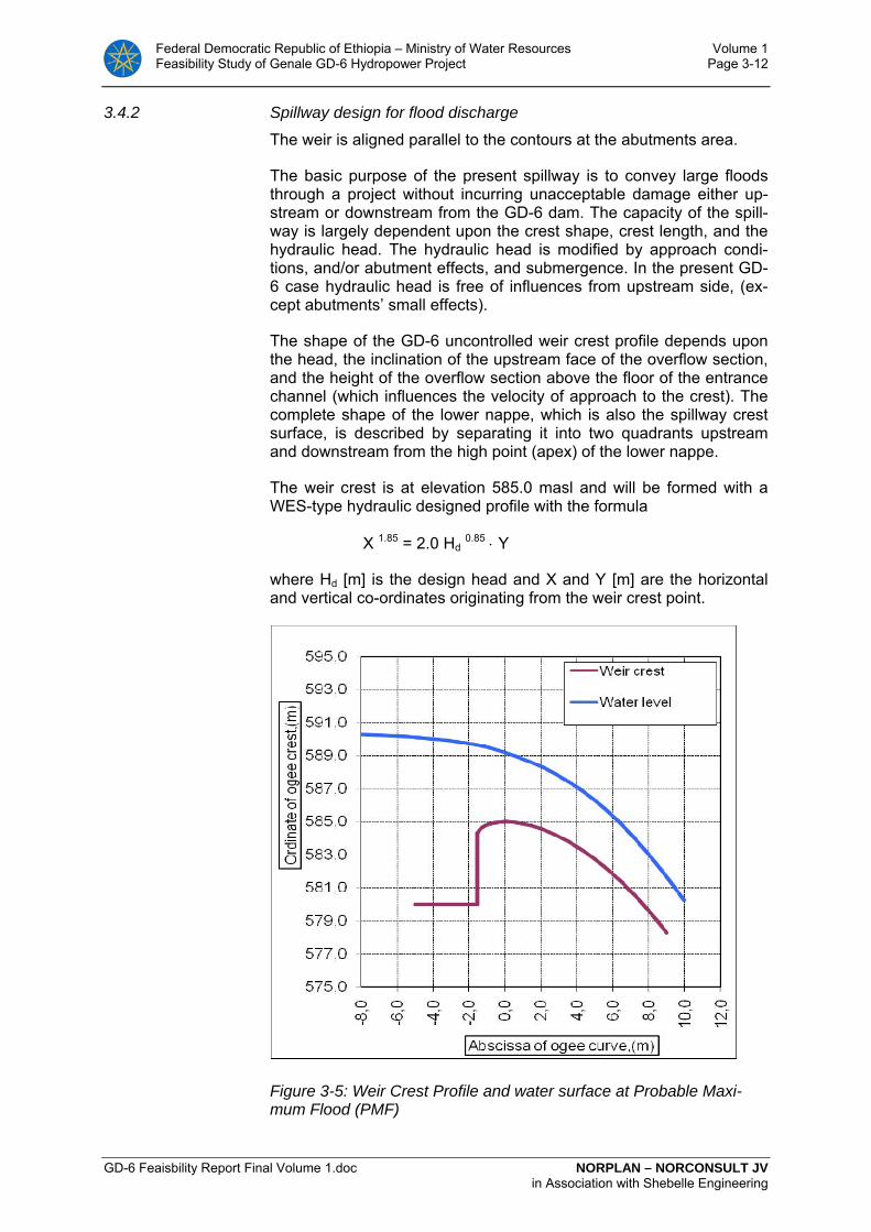
Federal Democratic Republic of Ethiopia – Ministry of Water Resources Volume 1 Feasibility Study of Genale GD-6 Hydropower Project Page 3-12
GD-6 Feaisbility Report Final Volume 1.doc NORPLAN – NORCONSULT JV in Association with Shebelle Engineering
3.4.2 Spillway design for flood discharge
The weir is aligned parallel to the contours at the abutments area.
The basic purpose of the present spillway is to convey large floods through a project without incurring unacceptable damage either up-stream or downstream from the GD-6 dam. The capacity of the spill-way is largely dependent upon the crest shape, crest length, and the hydraulic head. The hydraulic head is modified by approach condi-tions, and/or abutment effects, and submergence. In the present GD-6 case hydraulic head is free of influences from upstream side, (ex-cept abutments’ small effects).
The shape of the GD-6 uncontrolled weir crest profile depends upon the head, the inclination of the upstream face of the overflow section, and the height of the overflow section above the floor of the entrance channel (which influences the velocity of approach to the crest). The complete shape of the lower nappe, which is also the spillway crest surface, is described by separating it into two quadrants upstream and downstream from the high point (apex) of the lower nappe.
The weir crest is at elevation 585.0 masl and will be formed with a WES-type hydraulic designed profile with the formula
X 1.85 = 2.0 Hd 0.85 ⋅ Y
where Hd [m] is the design head and X and Y [m] are the horizontal and vertical co-ordinates originating from the weir crest point.
Figure 3-5: Weir Crest Profile and water surface at Probable Maxi-mum Flood (PMF)
Federal Democratic Republic of Ethiopia – Ministry of Water Resources Volume 1 Feasibility Study of Genale GD-6 Hydropower Project Page 3-13
GD-6 Feaisbility Report Final Volume 1.doc NORPLAN – NORCONSULT JV in Association with Shebelle Engineering
Side channel The side channel spillway control weir is placed alongside and ap-proximately parallel to the upper portion of the spillway discharge channel. Flow over the weir crest falls into a trough opposite the weir, turns approximately 90 degree left, and then continues into the main discharge channel.
In order not to make the channel flow turbulent and producing violent wave action with attendant vibrations and for having good hydraulic performance the flows in the trough is maintained at sub-critical stage. This has been achieved by establishing a control section (broad crested weir) downstream from the spill channel.
Because of turbulence and vibrations inherent in the planned side channel flow, the side channel requires a competent foundation such as rock. In this regard according to preliminary investigations, GD-6 dam site area has rock foundation up to elevations required for such structures, which make the selected type of spillway structurally fea-sible. The channel sides will be concrete lined and placed on a slope and anchored directly to the rock.
Side channel Assumed a trapezoidal section side channel trough, with 0.5:1 side slopes and a bottom width of 10.0 m, at start (upstream of the chan-nel) and 30.0 m at the end of the channel.
The side channel design is concerned only with the hydraulic action in the upstream reach of the discharge channel and is more or less independent of the details selected for the other spillway compo-nents. Computation of side channel trough has been done by trial-and-error computations.
According to the computations water surface elevation and channel’s bottom elevations are 585.0 masl and 575.7 masl respectively.
Spill channel Through the dam abutment and to the start point up to chute spillway (or stepped spillway) a spill channel structure must be constructed. The spill channel is always operated in sub-critical condition of flow. The following spill channel parameters are adopted:
• Rectangular section with variable widths,
• Bed slop i = 0.003,
• Length L = 165 m,
• Discharge Q = 2665 m3/sec.
Furthermore assumed, that a control section is placed downstream from the spill channel with its bottom 1.0 m above the elevation of the spill channel floor at the downstream end.
According to the design of the spill channel a broad crested weir at the end of the spill channel will have the following parameters:
• Weir crest elevation = 576.7 masl.
• Head over the weir, H = 6.6 m.
• Width of the weir, B = 3.70 m.
Federal Democratic Republic of Ethiopia – Ministry of Water Resources Volume 1 Feasibility Study of Genale GD-6 Hydropower Project Page 3-14
GD-6 Feaisbility Report Final Volume 1.doc NORPLAN – NORCONSULT JV in Association with Shebelle Engineering
• Crest length of the weir, L = 50 m.
Chute The flood from the spill channel will continue its flow through the chute. The flow condition will be super critical.
From the site topographical and geological conditions, and also from the above spill channel computation, the following chute parameters are determined:
• Trapezoidal section with width at bed = 30-50.
• Bed slop i1 = 0.136, and i2 = 0.320.
• Length L = 232 m.
The chute water surface profile computations gave the following re-sults:
• Velocity at the end of the chute = 34 m/s,
• Water depth at the end of the chute = 2.5 m,
• Froude number Fr is varying from 10 to 40
The maximum velocity along the chute, which is at the end of the chute, 34 m/s is high. Danger of cavitations and hence treatment of the chute channel bottom and sidewalls from possible cavitations may be considered near to the chute end area.
Ski jump At the end of the chute, a ski jump bucket structure is considered. This option of energy dissipation is the best option for such topogra-phy, as the Gd-6 chute terminal area topography.
When a free jet falls vertically into a pool in the Genale riverbed, a plunge pool will be scoured to a depth that is related to the discharge, the height of the fall, the depth of tail water and the bed material. The riverbed will be scoured because of the abrasive action of the water and sediment in the pool. Ultimately, the scour will reach a limiting depth as the energy of the jet is no longer able to remove bed mate-rial from the scour hole.
Data used and summary of the computations are presented in the following.

Federal Democratic Republic of Ethiopia – Ministry of Water Resources Volume 1 Feasibility Study of Genale GD-6 Hydropower Project Page 3-15
GD-6 Feaisbility Report Final Volume 1.doc NORPLAN – NORCONSULT JV in Association with Shebelle Engineering
Table 3-5: Ski Jump hydraulic and expected scour sizes computa-tions
Results
Design discharge, Q 2 500 m3/sec Width of ski jump bucket, B 75.0 m RW level upstream of control broad crested weir 580 masl
Bucket level 518.00 masl River bed at tail water area 511.00 masl Velocity at the bucket, V 34 m3/sec Radius of ski jump bucket curvature, R 2.0 m Angle, θ 45.0 degree Length of flight, L,w.surf. 92 m Expected scour depth below tail water, 33 m Length of flight, L,deep point. 220 m Length of scour at bottom 12 m Length of scour at top 115 m
3.4.3 Stepped spillway option
The main function of drop structures is to convey water from a higher to a lower elevation and to dissipate excess energy resulting from this drop.
Baffled apron drops may be used for nearly any decrease in water surface elevation where the horizontal distance to accomplish the drops is relatively short. Velocity at steps should remain constant near to 2 to 3 m/s or somewhat higher.
The main purpose of this stepped spillway design are:
• Determine the number of steps and height of each step,
• Determine height of baffle sill and step horizontal length, which is enough for energy dissipation entirely in the step,
• Compute conditions by which energy dissipation at the end of the stepped spillway to natural river channel will be performed,
According to the computations, the use of a stepped spillway require very wide spillway steps, (about 500 m), which make the option tech-nically not feasible.
3.4.4 Spillway capacity
The spillway capacity curve is illustrated in Figure 3-6 below.
The Genale GD-3 reservoir causes significant attenuation of floods. For an estimated PMF peak inflow of 3800 m3/s, the resulting peak outflow will be in the order of 1315 m3/s, resulting in a maximum flood at GD-6 of 2595 m3/s (PMF worst case scenario with GD-3 reservoir).

Federal Democratic Republic of Ethiopia – Ministry of Water Resources Volume 1 Feasibility Study of Genale GD-6 Hydropower Project Page 3-16
GD-6 Feaisbility Report Final Volume 1.doc NORPLAN – NORCONSULT JV in Association with Shebelle Engineering
The selected PMF is 2500 m3/s.
A freeboard at PMF-flood of 1.0 m has been chosen for the dam.
The spillway capacity is calculated by the common formula:
Q= C * L * h1.5
Where:
C= constant, reaching a maximum of 2.1
L= length of ogee crest, 100 m
h= overflow height
585
586
587
588
589
590
591
0 500 1000 1500 2000 2500 3000
Spillway flow [m3]
mas
l
Q10
00
PMF
Figure 3-6: Capacity curve of Genale GD-6 spillway
Bypass for minimum release A bypass for release of a minimum flow of 2.5 m3/s has been ar-
ranged in the diversion culvert. The Consultant suggests installing a small hydro unit to generate power from the compensation water re-lease downstream of the dam. The turbine will be a standard compact unit with horizontal shaft, with a load controller to ensure correct wa-ter release at all times.
Parallel to the turbine a redundant bypass system will be arranged to ensure compensation water release even if the generating unit is out of operation.
Project drawings B02 and B08 to B18

Federal Democratic Republic of Ethiopia – Ministry of Water Resources Volume 1 Feasibility Study of Genale GD-6 Hydropower Project Page 3-17
GD-6 Feaisbility Report Final Volume 1.doc NORPLAN – NORCONSULT JV in Association with Shebelle Engineering
3.5 Genale GD-6 - Power waterways, powerhouse and associated structures
Project drawings B10 to B17
3.5.1 General layout
: The power system of the Genale GD-6 scheme comprises the follow-
ing main elements:
• power intake as a separate structure including intake roller gate and trash rack. The trash rack can be closed by stop logs. The power intake is located at coordinates Easting 647 270, North 593 710
• a headrace pressure tunnel with a length of 4 700 m, Circular with diameter 9 m, basically unlined
• a surge system, consisting of a 120 m vertical shaft and a 500 m long surge tunnel Located at coordinates: E 651 120, N 593 725
• a construction adit at the downstream end of the headrace tun-nel
• two 40 m long penstocks to the turbines
• powerhouse complex including powerhouse cavern with two Francis turbines, draft tubes, draft tube gates, tailrace manifold, 4000 m2 surge chamber, transformer cavern, access tunnel, cable tunnel, emergency exit tunnel, etc. Locate at coordinate: E 651 980, N 593 850 (c unit 2)
• an unlined tailrace pressure tunnel, 11.4 km long, Circular with diameter 9 m, basically unlined
• tailrace outlet with arrangement for installation of stop logs
Locate at coordinate: E 663 270, N 596 300
The total length of the power waterway from the intake to the tailrace outlet, including the length of the pressure shaft, amounts to 16.1 km. The gross head gained by the diversion of Genale GD-6 amounts to 234 m, of which 60 m are gained by the Genale GD-6 dam.
The configuration of the headrace system is such that it can be emp-tied via the tailrace tunnel, while the tailrace must be pumped out, when emptying is required.
The major components of the Genale GD-6 power system are de-scribed in the following. Reference is made to 3.8 and 3.10 for the description of the mechanical and electrical components.
3.5.2 Power intake and headrace waterway
Project drawings B11 and B17
Federal Democratic Republic of Ethiopia – Ministry of Water Resources Volume 1 Feasibility Study of Genale GD-6 Hydropower Project Page 3-18
GD-6 Feaisbility Report Final Volume 1.doc NORPLAN – NORCONSULT JV in Association with Shebelle Engineering
Intake The intake with sill on elevation 566 masl is located in a cut on the right side of the river 900 m south of the dam. The intake trash rack (w x h = 10 x 12 m) is designed for partial obstruction. Stop logs can be set in front of the trash rack in the event of maintenance or repair works to be executed on the trash rack or intake gate.
The upstream of the intake cut is excavated deep, to allow for space for sediments to settle.
The trash rack cleaner will be installed on elevation 588.5, and run on rails embedded in a concrete slab.
Intake gates The top of a vertical intake shaft is located on the platform at eleva-tion 588.5. A roller gate with dimensions w x h = 5.5 x 8.2 m will be installed, with sill on elevation 565 masl. The gate will be designed to close under self-weight. Aeration tubes, filling bypasses and valves will be installed to create balanced water pressure after dewatering before re-opening of the gates.
Flushing device A sediment flushing system by the intake, is not incorporated. The sediment study shows, that with the upstream GD-3 reservoir the in-take will not be affected by sediments during normal lifetime.
The bottom outlet gate could be used for flushing by the dam site, but the necessity of flushing is expected to be limited.
Headrace tunnel Downstream of the power intake gates, the headrace tunnel contin-ues in slope 1:35.9 down to elevation 435 masl by the surge shaft, where slope is increased to approx 1:10 until it meets the combined construction adit and penstock chamber.
The headrace tunnel will be excavated from the adit by the power-house by full profile TBM (tunnel boring machine) dia. 9 m. According to the field investigations, the rock is of sound quality without major joints or fractures, and it is expected that the tunnel can remain basi-cally unlined, apart from occasional shotcrete support. Its standard profile will then be circular with diameter 9 m, corresponding to a cross section of 63.6 m2.
The velocity under full plant discharge (120 m³/s) is thus 1.89 m/s.
Surge facility Hydraulic calculations have shown that the headrace waterway of Genale GD-6 requires a surge facility to control hydraulic transients and pressure changes. The surge facility will include a 50 m2 vertical shaft of 120 m length and a sloping 50 m2 tunnel of 700 m total length. The adit portal will be at elevation 602 masl. (The basis for these data is given in the detailed hydraulic analyses in Volume 3, Annex 3 C).
Penstocks From a chamber at the downstream end of the headrace tunnel, two penstock of 4.2 m diameter, lead to the turbine inlet valves. The length of the penstocks are about 40 m each.
Rock trap A rock trap is arranged at the end of the headrace tunnel, on top of the penstocks.

Federal Democratic Republic of Ethiopia – Ministry of Water Resources Volume 1 Feasibility Study of Genale GD-6 Hydropower Project Page 3-19
GD-6 Feaisbility Report Final Volume 1.doc NORPLAN – NORCONSULT JV in Association with Shebelle Engineering
Access to the rock trap is provided via an adit tunnel from the main access tunnel, closed by a high pressure bulkhead.
Headrace excavation The headrace is planned to be drilled from the powerhouse end. The adit from the main access tunnel by the powerhouse is planned with a section suitable for transport of the TBM, and the cavern at the up-stream end of the penstock should be large enough for erection of the TBM.
3.5.3 Powerhouse complex
Project drawings B12, to B16
The powerhouse cavern is on the right bank of the river in a ridge some 4.5 km downstream of the dam. The site offers good geological conditions (see Chapter 7).
Powerhouse The powerhouse is designed to accommodate two turbine-generator sets. The main overall dimensions of the cavern are:
• length: 65 m • width: 17 m • height: 39 m (lowest point draft tube to cavern roof).
The turbine centre will be at el. 347.7 masl.
The vertical axis Francis turbines are embedded in reinforced con-crete and the generators are supported on an octagonal reinforced concrete plinth and enclosed in a reinforced concrete air-housing.
The turbine inlet valves are located within the cavern on the upstream side of the dismantling joint. They are accessible by the main station crane via hatch openings in the floors above. The hydraulic forces on the closed inlet valves will be transmitted through the bifurcation and penstock to the surrounding concrete and rock. Concrete girders supporting the crane rails are anchored to the cavern wall at an early stage for use during construction. If necessary, the girders will be fur-ther supported by concrete columns.
The powerhouse will accommodate all required rooms for safe opera-tion of the power plant. Electrical rooms are located on the generator floor at elevation 355.25. The turbine floor, el. 349.95, accommo-dates the turbine control cabinets and a mechanical workshop.
The control room, rescue room and wardrobes will be on the main floor, machine hall floor at el. 360.2. While some telecommunication, store room and ventilation will be placed above the control room.
Transformer cavern The transformers will be installed in a separate underground cavern parallel to the powerhouse cavern 20 m further downstream. Main cavern dimensions will be l x w x h = 25 x 12 x 13 m, in order to ac-commodate 2 three phase main step-up transformers.
Each transformer will be located in its own pen, which will be de-signed to prevent fire to spread from one transformer to the other.

Federal Democratic Republic of Ethiopia – Ministry of Water Resources Volume 1 Feasibility Study of Genale GD-6 Hydropower Project Page 3-20
GD-6 Feaisbility Report Final Volume 1.doc NORPLAN – NORCONSULT JV in Association with Shebelle Engineering
Each pen will be equipped with a high pressure water deluge system that would activate automatically in a fire event.
Two tunnels will be provided to take the isolated phase bus (IPB) ducts from the powerhouse to the transformer cavern. Each of these tunnels will serve to take the IPBs from one generator, i.e. 3 bus ducts will pass through each tunnel.
The floor in the transformer cavern will be on elevation 369.5 masl.
A tunnel branching off from the main access tunnel will provide ac-cess to the transformer cavern.
Cable tunnel The high voltage cables from the transformers will be taken to the surface, elevation 490, via a separate tunnel and shaft, totally 560 m. The tunnel will serve as an emergency escape from the powerhouse and will also serve ventilation purposes. The cable tunnel will start from main access tunnel, and the cables are taken in a concrete cul-vert in the access tunnel to the transformer gallery.
Access tunnel The access tunnel will be D-shaped, 7.5 x 7.5 m, with cross section about 50 m2. It will be 1150 m long, and have a slope of approx. 1:10. The tunnel portal will be on elevation 475 masl. The access tunnel will be large enough to permit two-way traffic during construction and allow passage of the largest items of equipment that will be brought into the powerhouse area. The transport of the TBM is expected to be the largest items to be transported in the tunnel.
3.5.4 Tailrace waterway and outlet
Manifold and gates Two concrete-lined draft tube tunnels convey the water from the draft tube outlets to the tailrace manifold. Each draft tube tunnel is equipped with a roller gate designed to close under self-weight. Dur-ing normal plant operation each gate is located in its respective gate chamber (combined with transformer gallery) that also contains hoist and associated equipment for operating the gate. The gate slot is normally covered by a watertight lid that has to be removed before setting the gate. The gates make it possible to isolate each draft tube tunnel from the common tailrace tunnel, when access to the turbines is necessary for maintenance and repair, without interrupting the op-eration of the other unit.
Tailrace surge facility A major surge chamber is required at the tailrace. The hydraulic analyses (see Volume 3, Annex 3 C) conclude on a surge “shaft” of 4000 m2. For that purpose the tailrace tunnel will be widened over a distance of 330 m, having the overall dimensions, 12 m wide and 32 m high. This will create a surge facility for safe operation at all Tail water levels.
Tailrace tunnel The tailrace tunnel will convey the water from the powerhouse back to Genale River. It will have a total length of 11.3 km in addition to the surge tunnel. The tunnel will be excavated by TBM technique similar to the headrace, it is expected that also the tailrace tunnel can be ba-sically unlined, apart from occasional shotcrete support. Its standard profile will be circular with diameter 9 m. Velocity under full plant dis-charge (120 m³/s) is 1.89 m/s.
Federal Democratic Republic of Ethiopia – Ministry of Water Resources Volume 1 Feasibility Study of Genale GD-6 Hydropower Project Page 3-21
GD-6 Feaisbility Report Final Volume 1.doc NORPLAN – NORCONSULT JV in Association with Shebelle Engineering
Excavation of the tailrace tunnel is planned to be performed by the same TBM, that first completes the headrace tunnel, and afterwards mobilised to the tailrace by the surge chamber. From here it drills al-most horizontal down to the tailrace outlet. In case of unforeseen drilling challenges affecting the overall progress of the construction works, it will be possible to start excavation of the tailrace by drill and blast (D&B) from the tailrace outlet. The tunnel should then be a D-shape tunnel with cross section 90 m2. The tunnel will then have a cross section sufficient for transporting the TBM out through the tun-nel.
Tailrace outlet The tailrace outlet sill is set on elevation 346.0 masl. On elevation 356.5 masl a platform is provided with road access and a structure that facilitates closure of the tailrace tunnel by Stop logs. The Stop logs can be set and removed under balanced pressure conditions by a mobile crane when dewatering and inspection of the tunnel is nec-essary. Upstream of the outlet structure, space for demobilising the TBM is planned.
Dewatering the tailrace, when and if required, must be by pumping at the tailrace outlet.
3.6 Genale GD-6 - River diversion during construction
Project drawing B06
General Design of river diversion structures at GD-6 will depend on the stag-ing of the GD-6 and GD-3 projects. If GD-6 implementation starts af-ter commissioning of the GD-3 project, the river flow is regulated, and design floods for the diversion is drastically reduced. The Consultant has in the design of the diversion structures assumed that construc-tion of the DG-6 dam starts before the completion of GD-3, and hence a design flood of 1300 m3/s (approx. 25-year) is used.
If GD-6 dam construction starts after GD-3 is commissioned the de-sign flood for the diversion will be in the range of 500 m3/s, reducing the costs of the diversion by more than 2 mill. USD.
Options Based on GD-6 dam site area topography and geological conditions, different river diversion alternatives have been investigated. For the different alternatives of rock-fill dam option two alternatives are stud-ied in detail (diversion through tunnel and diversion through concrete conduits under the dam body). If an RCC dam will be the final option, concrete culverts through the dam body will be the selected option.
Tunnels The tunnels are planned to be at the right bank of the river. This di-version option would include an approach channel, 400 m tunnel(s), upstream cofferdam and downstream cofferdam.
During optimization, attention has been given to different tunnel di-ameters and to different number of tunnels. Based on this computed required upstream cofferdam height final total costs of all tunnels and cofferdams are computed and the most economical combination of tunnel diameter, tunnel number and cofferdam height selected
Federal Democratic Republic of Ethiopia – Ministry of Water Resources Volume 1 Feasibility Study of Genale GD-6 Hydropower Project Page 3-22
GD-6 Feaisbility Report Final Volume 1.doc NORPLAN – NORCONSULT JV in Association with Shebelle Engineering
According to the detailed optimization results, the minimum total cost is for the following combinations:
• For 1 tunnels with diameter 14.0 m and cofferdam height 15.00 m.
• For 2 tunnels with diameter 10.0 m and cofferdam height 14.40 m.
• For 2 tunnels with diameter 11.0 m and cofferdam height 12.00 m.
• For 3 tunnels with diameter 9.0 m and cofferdam height 11.20 m.
It can be seen that major tunnelling works are required to divert floods during construction. The calculated cost for optimisation pur-poses is 16-17 mill. USD.
Culverts The concrete conduits (culverts) are also planned to be at the right bank of the river. This diversion option would include an approach channel, 230 m long concrete conduit(s), phase 1 cofferdam and phase 2 cofferdams. During phase 1 construction will required only one continues cofferdam, at phase 2, two cofferdams are required: one upstream and one downstream.
During optimization, different conduit sizes and different number of openings has been studied. Based on this study, the upstream cof-ferdam height required for phase 2 has been decided. Finally total costs of all conduits and cofferdams are computed and the most eco-nomical combination of single conduit section area, conduit number and cofferdam height has been selected.
According to the detailed optimization, the minimum total cost has been found for the following combinations:
• For 3 openings with cross section area of each 44.25m2 and phase 2 upstream cofferdam height 14.25m.
• For 3 openings with cross section area of each 38.00 m2 and phase 2 upstream cofferdam height 16.30 m.
• For 4 openings with cross section area of each 38.00 m2 and phase 2 upstream cofferdam height 10.70 m.
The total cost is calculated to be in the range of 12-14 mill USD for the options.
Conclusion The selected diversion concept is 3 concrete conduits of 42.5 m2 (6.5 x 6.5 m). One will be closed after the construction period, the second will be used to divert compensation flow of 2.5 m3/s, and in the third a bottom outlet gate will be installed.
3.7 Genale GD-6 - Access roads and camps
Project drawings G01 to G12 See also Annex 3D for detailed description of access roads.

Federal Democratic Republic of Ethiopia – Ministry of Water Resources Volume 1 Feasibility Study of Genale GD-6 Hydropower Project Page 3-23
GD-6 Feaisbility Report Final Volume 1.doc NORPLAN – NORCONSULT JV in Association with Shebelle Engineering
3.7.1 Access roads
Aims of the road investigation
For the feasibility study of the Genale GD6 hydropower project the access roads have been studied for the purpose of:
• Identifying the most feasible access routes into the various hy-dropower sites.
• Carrying out the preliminary design plan and profile drawings of all weather access roads and roads required for the construction, operation and maintenance of the hydropower project.
• Producing basic quantities for road construction and drainage for costing purposes.
The preliminary design outputs include drawings, a textural descrip-tion and quantity calculations.
Project appreciation
From 4 - 7 July, 2007, the site was visited by the project road engi-neer. The purpose of the visit was to gain first hand information of the site conditions and to note any particular constraints or advantages facing the provision of access roads. The visit was done by 4WD ve-hicle and on 7 July, aerial reconnaissance was done from helicopter. Much of the alignment along the Genale was also covered on foot.
Hydrological and hydraulic investigations
Selective hydrological investigations have been carried out to assess the run offs at critical points on the proposed road alignments and to estimate what type of drainage structures will be required. The Ra-tional method of estimating run-off has been used for catchments un-der 0.5 km2 and the HEC-HMS using Clarks Hydrograph system has been used for larger catchments.
Peak discharge 50 year return period was up to 390 m3/s for the Buti valley where it enters Genale River although, predominantly, this area is arid. Our investigations showed that despite being a very arid area with infrequent rainfall, precipitation when it does come is often in the form of intense storms. These storms produce significant quantities of rain and can result in sudden dramatic water flows. The run-off can be substantial, fast flowing and destructive in nature. The design life of the hydro scheme is some 50 years and we can expect the road to be affected by several such floods during it’s serviceable life. The Consultant has considered the flooding issue during the preliminary design and have tailored our approach with this in mind especially with regard to the following points:
• Any road crossing of the Koro or Buti valleys will require sub-stantial bridges to accommodate the design flood levels. This will significantly increase the construction costs. The Consult-ant therefore has positioned the main access road exclusively on the west side of the Buti alley to avoid providing such crossing structures.

Federal Democratic Republic of Ethiopia – Ministry of Water Resources Volume 1 Feasibility Study of Genale GD-6 Hydropower Project Page 3-24
GD-6 Feaisbility Report Final Volume 1.doc NORPLAN – NORCONSULT JV in Association with Shebelle Engineering
• Given the overall low frequency of rainfall, it should be ac-ceptable to build selective drainage structures, which will be allowed to overtop e.g. perforated drifts. This will imply it may not be possible to pass certain points for short periods during intense flooding.
• Roads following water courses should be placed above the estimated flood level
The estimated number and type of drainage structures is presented in the table below:
Table 3-6: Estimate of drainage structures Pipe culvert Ø=0.9m Slab Culverts Bridges
No Length(m) No. Length(m) No.
320 2486 67 167 1
Materials investigations
A geotechnical investigation has been conducted along the access route to the Genale GD-6 Hydro-power project area. The investigation was carried out to determine the local soil and rock types and the po-tential for building materials and ground conditions affecting the ac-cess roads. The field work was conducted from 13 November 2008 up to 20 November 2008 and the main conclusions are presented be-low.
Construction materials potential along the access route can be grouped as rock quarry, borrow, sand and water. Accordingly suffi-cient quantity of limestone and granitic gneiss for rocks are found along the route corridor. Similarly sufficient quantity of fine to coarse soil for borrow material can be found from low lying flat to undulating topography and Buti stream courses. Sand in patches is found espe-cially along the banks of Genale. Water can be obtained from Genale River. Sub grade soils appeared stable and no occurrence of soft foundation soils was observed.

Federal Democratic Republic of Ethiopia – Ministry of Water Resources Volume 1 Feasibility Study of Genale GD-6 Hydropower Project Page 3-25
GD-6 Feaisbility Report Final Volume 1.doc NORPLAN – NORCONSULT JV in Association with Shebelle Engineering
Design approach and methodology
Roads will be required both for the construction of the Genale GD6 project and later for the operational phase. These roads will be of various standards based on if they are temporary or permanent and if they will be heavily or lightly trafficked. The permanent roads should be built as all weather roads, as such they must be provided either with adequate drainage structures to safely pass all floodwaters or with structures, which will allow overtopping and have restricted ac-cess. For economical and environmental reasons, the roads having only light traffic can be built as single lane roads provided passing lay-bys are provided at intervisible intervals. All roads will be built to gravel standard only and maintained during the service life of the hy-droelectric plant.
The preliminary design of the access roads aims to provide suitable assess to the various hydropower elements comprising; powerhouse, dam, tailrace, camps, quarries, crushers, site camps, adits etc. Sev-eral sources of information have been utilised to define the access routes:
• 1:50,000 topographic maps
• Overlapping aerial photographs from 1991
• The project specific mapping at 1:10,000 with 5m contours
• GPS measurements of the existing tracks and paths
The Consultant has used the Novapoint road design program to de-sign the alignments. This program is based on AutoCAD as a plat-form and contains comprehensive highway design routines to pro-duce the various outputs. The project drawings: key plan, typical cross section and plan and profile drawings G01 to G12, indicate the roads sections and the type of roads.
Geometric design standards
In the design of the road the Consultant has sought to minimise con-structions costs and adverse environmental effects due to terrain in-trusion while at the same time providing appropriate geometric stan-dards for the transportation of the relevant project components. The roads are not intended to form a part of the public road network where higher design speed, aesthetics and geometrical standards are of higher priority. The roads have been designed as all weather gravel roads. The Consultant has selected a geometric design stan-dard consistent with other projects of similar nature. These standards are illustrated on the standard cross section drawing G02 and given in the table below:

Federal Democratic Republic of Ethiopia – Ministry of Water Resources Volume 1 Feasibility Study of Genale GD-6 Hydropower Project Page 3-26
GD-6 Feaisbility Report Final Volume 1.doc NORPLAN – NORCONSULT JV in Association with Shebelle Engineering
Table 3-7: Geometric Standards for the project roads.
Parameter Road Type Permanent Temporary
Design Speed – km/h 30 25 Minimum Hz Radius - m 25 18 Minumun Hz Radius – m Hairpin bends
15 12.5
Maximum Vertical Gradient - % 10 12 Maximum gradient through hairpins - %
5 5
Standard Crossfall - % 5 5 Maximum Superelevation - % 7 7 Number of Lanes1 1 – 2 1 – 2 Lane Width – m 3,5 3,0 Curve Widening - m 3,5 3,0 Widening for provision of guardrail - m 0,5 0,5 Type of Wearing Surface Gravel Gravel
Drainage features return flood design period Bridges Slab culverts Pipe culverts
50 25 5
25 10 5
Description of the road sections
The following table summarises all the designed road sections and lengths, they are described in more detail in annex 3D. Note that the access roads to the adits will not be required should the project tun-nelling be carried out by TBM.
1 For single lane roads, intervisible passing lay-bys shall be provided
Federal Democratic Republic of Ethiopia – Ministry of Water Resources Volume 1 Feasibility Study of Genale GD-6 Hydropower Project Page 3-27
GD-6 Feaisbility Report Final Volume 1.doc NORPLAN – NORCONSULT JV in Association with Shebelle Engineering
Table 3-8: Design Road section and Lengths Road Number
Description Length Notes
10,000 Main access road to Powerhouse from public highway
29+458 Permanent road, single lane up to Km 26+600, thereafter double
20,000 Access to upper dam and inlet
7+230 Permanent, double road
21,000 Access to camp 1+966 Permanent, double road 22,000 Access to lower dam,
quarries and crushers 2+966 Temporary, double road
23,000 Upper access to dam, quarries and crushers
0+441 Temporary, double road
24,000 Access to adit on head-race tunnel
1+066 Temporary, double road
30,000 Access to tailrace 16+715 Permanent single lane road, restricted access
31,000 Access up Kebyeya Val-ley to camp, workshop and dumps
1+712 Temporary, double road
32,000 Access to tailrace adit 1 0+547 Temporary, double road 33,000 Access to tailrace adit 2 0+783 Temporary, double road
Total 62+885
3.7.2 Camps
An area has been designated for the main camp and appears on road drawing G07. The site is on an elevated plateau some 140 m above the Genale River. The camp will be accessed via road 21,000 and will be built to permanent, double lane standard. The camp will be ap-proximately 6 kilometres by road from both the powerhouse and the dam site. This site can be used both for the temporary camp during the construction period and for the permanent camp during the opera-tional period.
The administrative camp is proposed to be located near the switch-yard and the portal to the power station.
A main construction camp will be required and several temporary camps which can be moved as work progresses.
Separate camps will be required at the different construction sites and for the road construction, which will be located and established by the road contractor.
Basic requirements for housing are shown in Table 3-9: and for ad-ministration and various facilities in Table 3-10.

Federal Democratic Republic of Ethiopia – Ministry of Water Resources Volume 1 Feasibility Study of Genale GD-6 Hydropower Project Page 3-28
GD-6 Feaisbility Report Final Volume 1.doc NORPLAN – NORCONSULT JV in Association with Shebelle Engineering
Table 3-9: Housing requirements Description Housing Housing area (m2)
No. of families
Families pr. block
No of blocks
One block All blocks
Management Staff
2 1 2 150 300
High-level staff 15 1 15 100 1 500
Middle-level staff 20 2 10 80 800
Lower-level staff 30 2 15 60 900
Guards 40 2 20 60 1 200
Total 107 63 4 700
Table 3-10: Plant administration and various facilities Item List of rooms Quantity Area & Remarks
1 Offices 15 230 m2
2 Meeting Room 1 100 m2
3 Store & storeman office 1 200 m2
4 Archives 1 100 m2
5 Conference Hall of 100 seats 1 180 m2
6 Library 1 40 m2
7 Wearing Rooms (for male & female) 2 60 m2
8 Misc 50 m2
Total area of the three floors 960 m2
Reference is made to Annex 3D for more detailed descriptions
Power supply Construction power will be supplied from the main grid through a double circuit 33 kV transmission line to be constructed from the 66/33 kV substation at Negele.
Waste management Waste is handled according to its nature and potential negative im-pacts. Therefore, all waste generated by the camp will be classified in order to be handled correctly. Detailed classification of wastes, meth-ods of treatment and disposal of each type should be studied and ar-rangements be made during final design work.
Telecommunications and information technology
Good communications are essential for plant of this nature. A reliable telecommunication system is required for proper operation of the plants.
Costing This work will adopt the standards of Ethiopian Electric Power Corpo-ration (EEPCo) for camp facility requirements. From practical experi-ence on recent hydropower projects, about USD 10 million can be al-
Federal Democratic Republic of Ethiopia – Ministry of Water Resources Volume 1 Feasibility Study of Genale GD-6 Hydropower Project Page 3-29
GD-6 Feaisbility Report Final Volume 1.doc NORPLAN – NORCONSULT JV in Association with Shebelle Engineering
located for camp construction for both categories (i.e. for the con-struction period as well as for operational phases).
3.8 Genale GD-6 - Mechanical equipment
Project drawings B11 to B17
3.8.1 General
The hydro-mechanical equipment will consist of two main packages:
Mechanical Equipment, comprising:
• Turbines with inlet valves and governors
• Compensation water turbine with valves and controls • Powerhouse cranes • Cooling and dewatering systems • Auxiliary equipment • Ventilation (HVAC)
Hydraulic Steelworks, comprising:
• Intake with necessary gate and equipment
• Dam bottom outlet gate with stop logs • Adit gates for headrace tunnel • Penstocks • Draft tube gates and tailrace stop logs
3.8.2 Turbine selection
Turbine type Based on the design head and turbine flow, vertical Francis turbines represent the only practical solution.
Number of units The Consultant has made generation calculations based on the plant’s flow duration curve to evaluate the installation of two or three units in Genale GD6 power plant. The costs increase as number of units increase, but at the same time the generation may increase enough to make a larger number of units the optimum cost/benefit so-lution.
In the case of Genale GD6, the flow duration curve does not favour the use of three units relative to two. The increase in generation is calculated to be only 2GWh. This additional generation does not jus-tify the increased cost of three units.
The reason for this can be seen from the efficiency curves, (see Fig-ure 3-7 below) showing the difference in efficiency at various flows for the two alternatives:

Federal Democratic Republic of Ethiopia – Ministry of Water Resources Volume 1 Feasibility Study of Genale GD-6 Hydropower Project Page 3-30
GD-6 Feaisbility Report Final Volume 1.doc NORPLAN – NORCONSULT JV in Association with Shebelle Engineering
Combined efficiency 2 and 3 units
0.84
0.86
0.88
0.9
0.92
0.94
0.96
0 20 40 60 80 100 120
Plant flow [m3/s]
Com
bine
d ef
ficie
ncy
[-]
3 units2 units
Figure 3-7: Efficiency curves showing the difference in efficiency at various flows for the two alternatives
Flows between 40 and 58 m3/s favours 2 units and flows from 60 to 80 m3/s favours 3 units.
A Francis turbine with the considered characteristics will normally have a lower load limit for continuous operation of approximately 40% of its maximum load. This means that the station will be able to oper-ate continuously from around 50 MW (minimum load for one unit) to 250.8 MW (maximum load for two units). The combined efficiency curve for the station will have two maximums, for one and two units in operation, as shown in the figure above. Temporary operation below the “minimum” load will be possible, but should normally be avoided due to the drop in efficiency. The size of the intake reservoir (34 mil-lion m3) combined with the planned release pattern from Genale GD3 implies that the “minimum” load restriction has no practical impact on operation.
Operation pattern In the long term, the operation of Genale GD-6 must be optimised in relation with the operation of its reservoir, taking also into account the operation of Genale GD-3 station, upstream of Genale GD-6.
Genale GD6 will operate on the water release from Genale GD-3 with some additional inflow. The normal mode of operation will be water level control, but the 5 meter possible drawdown allows for daily peaking operation in periods with low inflow: Up to 160 hours of op-eration of 1 unit at full load or 80 hours of operation of 2 units at full load.
3.8.3 Main turbine data
Design head The level in the intake reservoir will vary between 585.0 masl at Full Storage Level (FSL) and 580.0 masl at Minumum Operation Level (MOL). Genale GD6 will operate to supply firm energy most of the

Federal Democratic Republic of Ethiopia – Ministry of Water Resources Volume 1 Feasibility Study of Genale GD-6 Hydropower Project Page 3-31
GD-6 Feaisbility Report Final Volume 1.doc NORPLAN – NORCONSULT JV in Association with Shebelle Engineering
time with some peaking operation and full load operation during high flow seasons. The FSL will therefore be the basis for the turbine net design head. This level together with a Tail water of 351 and the Head loss corresponding to two units in operation (6.0 m) are used to define the design head for the turbine:
Net Desing Head = 585 -351 –6 = 228 m
The rating curves for Tail water and headwater shows an increase to +6 and +5 meters respectively when reaching PMF. This will not im-pact the decision on turbine net design head, as flood situations will occur seldom with GD3 in operation upstream.
Rotational speed One main choice in determining the turbine data is the rotational speed. A higher speed means smaller dimensions for the turbine and a lower price, but it also requires a larger submergence. Higher speed will also give a more “pointly” efficiency curve, less flexible tur-bine, and thereby reduce total generation. The generator price will also be reduced with a higher speed. Optimisation calculations car-ried out have lead to the choice of a rotational speed of 300 rpm, and a moderate submergence. The turbine distributor centreline will be approximately 3.3 m below the minimum water level corresponding to one unit in operation. The discharge for best efficiency will be ap-proximately 80 to 85% of the full-load discharge.
The submergence requirement as well as the position of the point of best efficiency depend on the specific turbine design and will vary slightly between different suppliers.
The main turbine data are summarised in Table 3-11 below.
Table 3-11: Main turbine data - Genale GD-6
Main Data Arrangement: Vertical Turbine net design head: 228 m Turbine power at net design head: 125.4 MW Turbine flow at net design head: 60 m3/s Max. head: 232.5 m Turbine power at max. head 129.1 MW Turbine flow at max. head 60.6 m3/s Turbine speed: 300 rpm Runaway speed, max. head (approx.): 490 rpm Turbine runner centre: el.347.7 Spiral casing centreline submergence: 3.3 m Approximate Data Runner outlet diameter: 2500 mm Turbine cover diameter: 4400 mm

Federal Democratic Republic of Ethiopia – Ministry of Water Resources Volume 1 Feasibility Study of Genale GD-6 Hydropower Project Page 3-32
GD-6 Feaisbility Report Final Volume 1.doc NORPLAN – NORCONSULT JV in Association with Shebelle Engineering
3.8.4 Turbine design
Sediments Earlier studies indicate that the sediment load in the Genale River is approximately 1 mill tons annually. Sediment composition and particle distribution 13% sand, 32% silt and 55% clay2. The remaining 10% is bed load. The size of the intake reservoir (close to 34 million m3 ) and the GD-3 reservoir, makes it reasonable to assume that most abrasive sediments will be deposited in the reservoir, and that sand erosion on the turbine will be a minor problem. The intake is also lo-cated high in the reservoir as the useable drawdown is only 5 meters.
Materials The steel structures of the main turbine parts such as spiral casing, cov-ers, stay ring and draft tube, will be made from fine grained carbon steel according to approved standards. Stainless steel will be used for runner, guide vanes, and waterway surfaces, such as upper and lower cover and also the upper part of the draft tube. Guide vanes and all moving parts of the operating mechanism will have self-lubricating, long life bushings. All non-mating ferrous surfaces will be coated with two-component epoxy paint.
Shaft seal The turbine shaft seal represents a particularly important aspect of the design. Experience shows that failure of this element can reduce the reliability and the availability of the units. Different type of designs (based on sealing rings or based on a “contact free” solution) can work, but it is essential that the supplier has a good experience re-cord of the specific design. If the design requires a separate sealing water supply of it is very important that a proper filtration system is used.
Runner dismantling To avoid removing the generator rotor during runner replacement, as well as change or repairs of labyrinth seal rings, the design will allow the turbine runner to be dismantled downwards after having removed the draft tube cone and the lower cover through a recess in the tur-bine foundation. Runners and other turbine parts to be replaced or repaired can be hoisted to the machine hall floor through hatches in the powerhouse floors.
3.8.5 Main inlet valves
Type of valve The main inlet valves represent an important element for the reliability of operation of the plant: they are the first means of closure of the wa-terway, and a failure occurring on a valve may require the waterway to be emptied, which means total loss of generation for a period.
With the given head, two types of valves can be considered:
• Butterfly valves
• Spherical valves
The spherical valves have no obstruction in the waterway (no head loss) and will be given the same diameter as the spiral casing inlet. Its disadvantage is that it is a comparatively heavy and expensive component.
2 Report # GDMP-P2D.II-E.I March 2006

Federal Democratic Republic of Ethiopia – Ministry of Water Resources Volume 1 Feasibility Study of Genale GD-6 Hydropower Project Page 3-33
GD-6 Feaisbility Report Final Volume 1.doc NORPLAN – NORCONSULT JV in Association with Shebelle Engineering
The closing body (disc) in a butterfly valve represents an obstruction in the waterway causing a head loss. The diameter should be larger than for a spherical valve in order to reduce the loss. In addition, the maximum gross velocity should not exceed 7 m/s as a rule, and sometimes as low as 6 m/s to avoid vibration problems in the closing body. The price for a butterfly valve would still be lower than that of a spherical valve.
Optimisations carried out on a number of projects show that butterfly valves give an altogether better economy for lower heads, and spherical valves for higher heads, the break point being around 200 m head. Genale GD6 has 228 meters net design head, and the opti-misation performed favours spherical valves. Another advantage of the spherical valve is that it is easier to arrange revision seal than for a butterfly valve.
Operating system Counterweight closing, with a hydraulic cylinder for opening gives a very high reliability. Formerly this has been used mostly for small to medium size valves, but its use is extending gradually also to large size valves. Although it may represent an unusual solution for the size of the valves considered here, it presents no technical difficulties. The station layout has to accommodate counterweight arms.
A system based on a double acting hydraulic cylinder for opening / closing together with an accumulator is also a possibility, but its safety of operation will never be able to match that of a counterweight based system, even if redundant systems are used for the accumula-tor.
The valve will include a by-pass system permitting to operate the valve at equalised pressures during normal operation conditions. The service seal and the revision seal may be either metallic or rubber type.
Weight The spherical valves will have a diameter around 2 500 mm (exact dimension will be given by the turbine spiral case inlet diameter of the individual manufacturer). Preliminary estimations indicate an erection weight in the range of 160 tons for the spherical valve. The valve can be brought to the station in separate pieces, thus reducing signifi-cantly the transport weight.
Main data The main data for the main inlet valves are summarised in Table 3-12 below:
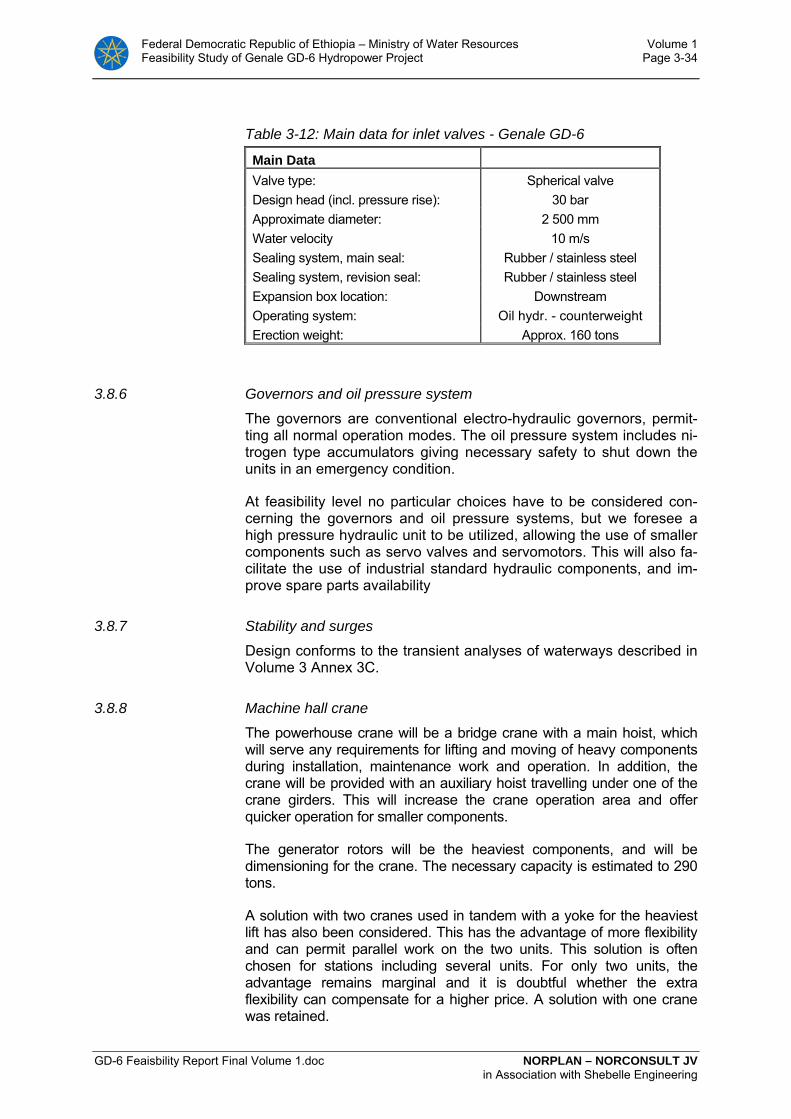
Federal Democratic Republic of Ethiopia – Ministry of Water Resources Volume 1 Feasibility Study of Genale GD-6 Hydropower Project Page 3-34
GD-6 Feaisbility Report Final Volume 1.doc NORPLAN – NORCONSULT JV in Association with Shebelle Engineering
Table 3-12: Main data for inlet valves - Genale GD-6
Main Data Valve type: Spherical valve Design head (incl. pressure rise): 30 bar Approximate diameter: 2 500 mm Water velocity 10 m/s Sealing system, main seal: Rubber / stainless steel Sealing system, revision seal: Rubber / stainless steel Expansion box location: Downstream Operating system: Oil hydr. - counterweight Erection weight: Approx. 160 tons
3.8.6 Governors and oil pressure system
The governors are conventional electro-hydraulic governors, permit-ting all normal operation modes. The oil pressure system includes ni-trogen type accumulators giving necessary safety to shut down the units in an emergency condition.
At feasibility level no particular choices have to be considered con-cerning the governors and oil pressure systems, but we foresee a high pressure hydraulic unit to be utilized, allowing the use of smaller components such as servo valves and servomotors. This will also fa-cilitate the use of industrial standard hydraulic components, and im-prove spare parts availability
3.8.7 Stability and surges
Design conforms to the transient analyses of waterways described in Volume 3 Annex 3C.
3.8.8 Machine hall crane
The powerhouse crane will be a bridge crane with a main hoist, which will serve any requirements for lifting and moving of heavy components during installation, maintenance work and operation. In addition, the crane will be provided with an auxiliary hoist travelling under one of the crane girders. This will increase the crane operation area and offer quicker operation for smaller components.
The generator rotors will be the heaviest components, and will be dimensioning for the crane. The necessary capacity is estimated to 290 tons.
A solution with two cranes used in tandem with a yoke for the heaviest lift has also been considered. This has the advantage of more flexibility and can permit parallel work on the two units. This solution is often chosen for stations including several units. For only two units, the advantage remains marginal and it is doubtful whether the extra flexibility can compensate for a higher price. A solution with one crane was retained.

Federal Democratic Republic of Ethiopia – Ministry of Water Resources Volume 1 Feasibility Study of Genale GD-6 Hydropower Project Page 3-35
GD-6 Feaisbility Report Final Volume 1.doc NORPLAN – NORCONSULT JV in Association with Shebelle Engineering
The main crane hook will be capable of lifting the tallest component off the transporting vehicle and both main and auxiliary hooks will reach as far down as required to serve the turbine cellar.
The crane will have a radio control allowing operation from any part of the powerhouse.
Table 3-13: Main data for machine hall crane - Genale GD-6
Main Data
Main hoist capacity, approximate: 290 t Auxiliary hoist capacity: 20 t Bridge span, distance between rails (approx): 16.5 m Crane travel: 62m Hoisting height (approx): 25 m Highest hook position above machine hall floor:
9 m
3.8.9 Cooling water system
The solutions used for cooling water systems vary widely, due to the differences in water quality, but also as a result of differences of hab-its and traditions. The adequacy of the solutions chosen for the cool-ing water system can have a large influence on operation. Problems with the filtration as well as organic growth in piping and coolers are the main difficulties that may arise in relation to the cooling water sys-tem.
The design requirements are numerous and may to a certain point be contradictory:
• Simplicity
• Sufficient redundancy
• Limit the number of elements for which maintenance works will impose to shut down the whole station
• Cooling water requirements during shut-down of the units in case of loss of power
Considered solution
The system considered at this stage is relatively traditional. It in-cludes mainly:
Water supply Water pumped from the Tail water or supplied from the turbine laby-rinth seals, or a combination of both.
The solution of using the turbine labyrinth seal water is attractive as it supplies water “for free”, with an adequate pressure and filtrated through the turbine labyrinth seals. This solution is, however, not of-fered by all turbine suppliers.
The alternative to labyrinth seal water is to pump the water from the Tail water. For the head considered, taking the water from the pres-sure shaft is not an economic solution as its pressure exceeds by far
Federal Democratic Republic of Ethiopia – Ministry of Water Resources Volume 1 Feasibility Study of Genale GD-6 Hydropower Project Page 3-36
GD-6 Feaisbility Report Final Volume 1.doc NORPLAN – NORCONSULT JV in Association with Shebelle Engineering
what is necessary for cooling purposes. Also, pressure reducing valves are often causing operational problems.
Cooling water tank All water will be lead to the cooling water tank. The tank has a double function of sedimentation basin and of cooling water reserve for the bearings for stop of the units in case loss of power. The tank includes two parallel compartments permitting removal of sediments in one while continuing operation in the other one.
Filter system From the tank, the water goes through an automatic filter with mesh size around 1 mm. A manual filter permits to by-pass the automatic filter if required.
Water to consumers After the filters, water is distributed by gravity to the different consum-ers, i.e. the generator air coolers, the turbine and generator bearing coolers, the turbine governor cooler, the transformer coolers and the ventilation coolers. Total cooling water quantity is in the range of 76 l/s for each unit and 25 l/s for each transformers and 18 l/s for ventila-tion, giving a total capacity close to 220 l/s. From the coolers, water is lead back to the Tail water.
Alternative solution
Alternatively, a two stage cooling water system may be considered: a primary system using raw river water for cooling of heat exchangers (water supply as described above), and a closed secondary circuit solution with circulation pumps for circulating the water between the heat exchangers and the different coolers. It is important to choose heat exchangers that are easy to clean, also during operation. The system is, however, expensive due to the additional heat exchangers, and will also increase the amount of cooling water needed due to the reduced temperature differences. The circulating cooling water can be treated to avoid organic growth and calcium deposits.
3.8.10 Drainage and dewatering systems
Separate systems are foreseen for drainage of the different floors of the power station, and for dewatering of the units and of the lower part of the pressure shaft.
Drainage system
Seepage from the rock and other leakages from the different floors of the power station will be lead to the drainage pit located between the draft tubes of the two units. From the drainage pit, three electric sub-mersible pumps, each with a capacity around 20 l/s will be used to pump up the water to the tailrace tunnel, downstream of the draft tube gates.
The drainage system will also include an emergency ejector pump that will operate independent of all electrical systems, being activated by the rising water level in the drainage pit. The capacity foreseen for the ejector is 60 l/s. Alternatively a diesel generated pump may be in-stalled in place of the ejector pump.

Federal Democratic Republic of Ethiopia – Ministry of Water Resources Volume 1 Feasibility Study of Genale GD-6 Hydropower Project Page 3-37
GD-6 Feaisbility Report Final Volume 1.doc NORPLAN – NORCONSULT JV in Association with Shebelle Engineering
Dewatering system
One solution for dewatering the turbines is to empty the water from the draft tubes into the drainage pit, which is then emptied by the normal drainage pumps. Such a procedure represents, however, al-ways a risk of flooding of the station in case of wrong operation.
A separate closed dewatering system taking the water from the draft tubes and discharging it in the tailrace tunnel is therefore considered. The system will also be used for dewatering the last portion of the penstocks during emptying of headrace tunnel. The system will in-clude two pumps with a capacity determined to give a reasonable time for dewatering of the turbines and of the lower part of the pres-sure shaft. A capacity around 20 l/s per pump should be realistic. From the lowest point of each spiral casing, a small drainage pipe with valve will lead the remaining water to the power station drainage sump.
3.8.11 Ventilation and air conditioning
Reference is made to Section 3.11.
3.8.12 Workshop
The station will include a small workshop with hand tools and small machine tools (as a drilling column). A compressed air system for op-eration tools and oil treatment equipment will also be included.
3.8.13 Intake equipment
Basic data
The intake equipment including thrash rack, intake gate and related equipment has to be placed such that at a safe submergence of the intake in order to guarantee that no air will be drawn into the head-race tunnel when operating at lowest regulated level (elevation 580).
In addition to the equipment related to the intake itself, a combined bottom outlet and sediment flushing gate is located in one of the by-pass conduits under through the dam, used during construction.
Guides for revision stop logs at intake
A set of stop logs are considered in front of the trash rack, with a width and height slightly larger than those of the trash racks. The stop logs would have following main data:
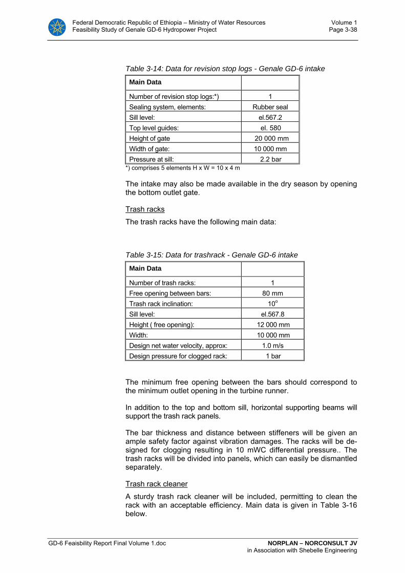
Federal Democratic Republic of Ethiopia – Ministry of Water Resources Volume 1 Feasibility Study of Genale GD-6 Hydropower Project Page 3-38
GD-6 Feaisbility Report Final Volume 1.doc NORPLAN – NORCONSULT JV in Association with Shebelle Engineering
Table 3-14: Data for revision stop logs - Genale GD-6 intake
Main Data
Number of revision stop logs:*) 1 Sealing system, elements: Rubber seal Sill level: el.567.2 Top level guides: el. 580 Height of gate 20 000 mm Width of gate: 10 000 mm Pressure at sill: 2.2 bar
*) comprises 5 elements H x W = 10 x 4 m
The intake may also be made available in the dry season by opening the bottom outlet gate.
Trash racks
The trash racks have the following main data:
Table 3-15: Data for trashrack - Genale GD-6 intake
Main Data
Number of trash racks: 1 Free opening between bars: 80 mm Trash rack inclination: 10o
Sill level: el.567.8 Height ( free opening): 12 000 mm Width: 10 000 mm Design net water velocity, approx: 1.0 m/s Design pressure for clogged rack: 1 bar
The minimum free opening between the bars should correspond to the minimum outlet opening in the turbine runner.
In addition to the top and bottom sill, horizontal supporting beams will support the trash rack panels.
The bar thickness and distance between stiffeners will be given an ample safety factor against vibration damages. The racks will be de-signed for clogging resulting in 10 mWC differential pressure.. The trash racks will be divided into panels, which can easily be dismantled separately.
Trash rack cleaner
A sturdy trash rack cleaner will be included, permitting to clean the rack with an acceptable efficiency. Main data is given in Table 3-16 below.
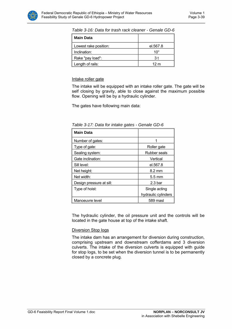
Federal Democratic Republic of Ethiopia – Ministry of Water Resources Volume 1 Feasibility Study of Genale GD-6 Hydropower Project Page 3-39
GD-6 Feaisbility Report Final Volume 1.doc NORPLAN – NORCONSULT JV in Association with Shebelle Engineering
Table 3-16: Data for trash rack cleaner - Genale GD-6
Main Data
Lowest rake position: el.567.8 Inclination: 10° Rake "pay load": 3 t Length of rails: 12 m
Intake roller gate
The intake will be equipped with an intake roller gate. The gate will be self closing by gravity, able to close against the maximum possible flow. Opening will be by a hydraulic cylinder.
The gates have following main data:
Table 3-17: Data for intake gates - Genale GD-6
Main Data
Number of gates: 1 Type of gate: Roller gate Sealing system: Rubber seals Gate inclination: Vertical Sill level: el.567.8 Net height: 8.2 mm Net width: 5.5 mm Design pressure at sill: 2.3 bar Type of hoist: Single acting
hydraulic cylinders Manoeuvre level 589 masl
The hydraulic cylinder, the oil pressure unit and the controls will be located in the gate house at top of the intake shaft.
Diversion Stop logs
The intake dam has an arrangement for diversion during construction, comprising upstream and downstream cofferdams and 3 diversion culverts. The intake of the diversion culverts is equipped with guide for stop logs, to be set when the diversion tunnel is to be permanently closed by a concrete plug.
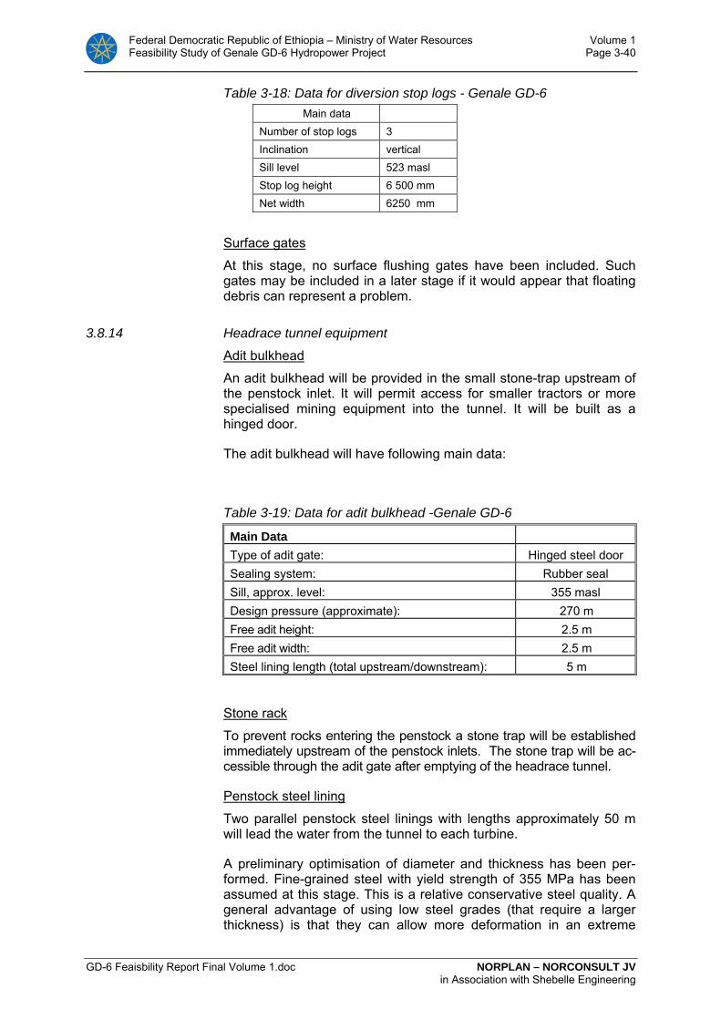
Federal Democratic Republic of Ethiopia – Ministry of Water Resources Volume 1 Feasibility Study of Genale GD-6 Hydropower Project Page 3-40
GD-6 Feaisbility Report Final Volume 1.doc NORPLAN – NORCONSULT JV in Association with Shebelle Engineering
Table 3-18: Data for diversion stop logs - Genale GD-6 Main data Number of stop logs 3 Inclination vertical Sill level 523 masl Stop log height 6 500 mm Net width 6250 mm
Surface gates
At this stage, no surface flushing gates have been included. Such gates may be included in a later stage if it would appear that floating debris can represent a problem.
3.8.14 Headrace tunnel equipment
Adit bulkhead
An adit bulkhead will be provided in the small stone-trap upstream of the penstock inlet. It will permit access for smaller tractors or more specialised mining equipment into the tunnel. It will be built as a hinged door.
The adit bulkhead will have following main data:
Table 3-19: Data for adit bulkhead -Genale GD-6
Main Data Type of adit gate: Hinged steel door Sealing system: Rubber seal
Sill, approx. level: 355 masl Design pressure (approximate): 270 m Free adit height: 2.5 m Free adit width: 2.5 m Steel lining length (total upstream/downstream): 5 m
Stone rack
To prevent rocks entering the penstock a stone trap will be established immediately upstream of the penstock inlets. The stone trap will be ac-cessible through the adit gate after emptying of the headrace tunnel.
Penstock steel lining
Two parallel penstock steel linings with lengths approximately 50 m will lead the water from the tunnel to each turbine.
A preliminary optimisation of diameter and thickness has been per-formed. Fine-grained steel with yield strength of 355 MPa has been assumed at this stage. This is a relative conservative steel quality. A general advantage of using low steel grades (that require a larger thickness) is that they can allow more deformation in an extreme

Federal Democratic Republic of Ethiopia – Ministry of Water Resources Volume 1 Feasibility Study of Genale GD-6 Hydropower Project Page 3-41
GD-6 Feaisbility Report Final Volume 1.doc NORPLAN – NORCONSULT JV in Association with Shebelle Engineering
situation, thus giving an increased safety compared to a high-grade steel which will be more brittle. Use of a higher grade steel will nor-mally reduce the costs and may be considered as a later stage.
Full external pressure has been assumed in the calculations, which is a conservative assumption. However, with the head and diameters considered, the thickness requirements due to external pressure are practically matching those due to internal pressure, and are not rep-resenting a supplementary requirement.
A rate of 5 US cent per kWh has been assumed to value the losses in the diameter optimisation.
The main data of the penstock steel lining and branch pipes are as follows:
Table 3-20: Data for penstock steel lining.
Main Data
Maximum internal pressure: 288 m Maximum external pressure: 270 m Steel lining length: 50 m Internal diameter: 4.2 m Lining thickness: 34 mm Total weight of delivery: 200 ton
The solution with two separate penstocks leading the water from a widening of the headrace tunnel is chosen because of the tunnel lay-out and because it will generally simplify the works in all aspects, in-cluding design, fabrication, transport, erection and control.
3.8.15 Tailrace tunnel equipment
Draft tube gates
A complete draft tube gate with electric wire hoist and guides will be installed for each turbine.
An outlet velocity of approximately 2 m/s has been assumed at this stage. The main data for the gates are given in Table 3-21
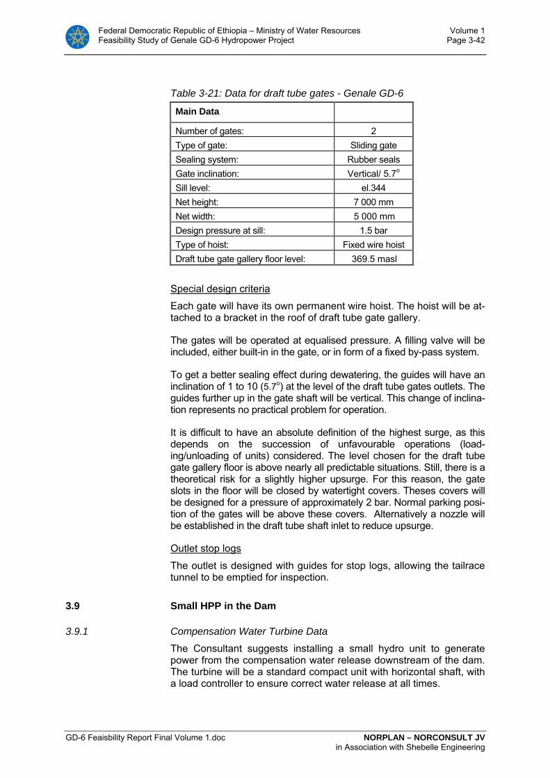
Federal Democratic Republic of Ethiopia – Ministry of Water Resources Volume 1 Feasibility Study of Genale GD-6 Hydropower Project Page 3-42
GD-6 Feaisbility Report Final Volume 1.doc NORPLAN – NORCONSULT JV in Association with Shebelle Engineering
Table 3-21: Data for draft tube gates - Genale GD-6
Main Data
Number of gates: 2 Type of gate: Sliding gate Sealing system: Rubber seals Gate inclination: Vertical/ 5.7o
Sill level: el.344 Net height: 7 000 mm Net width: 5 000 mm Design pressure at sill: 1.5 bar Type of hoist: Fixed wire hoist Draft tube gate gallery floor level: 369.5 masl
Special design criteria
Each gate will have its own permanent wire hoist. The hoist will be at-tached to a bracket in the roof of draft tube gate gallery.
The gates will be operated at equalised pressure. A filling valve will be included, either built-in in the gate, or in form of a fixed by-pass system.
To get a better sealing effect during dewatering, the guides will have an inclination of 1 to 10 (5.7o) at the level of the draft tube gates outlets. The guides further up in the gate shaft will be vertical. This change of inclina-tion represents no practical problem for operation.
It is difficult to have an absolute definition of the highest surge, as this depends on the succession of unfavourable operations (load-ing/unloading of units) considered. The level chosen for the draft tube gate gallery floor is above nearly all predictable situations. Still, there is a theoretical risk for a slightly higher upsurge. For this reason, the gate slots in the floor will be closed by watertight covers. Theses covers will be designed for a pressure of approximately 2 bar. Normal parking posi-tion of the gates will be above these covers. Alternatively a nozzle will be established in the draft tube shaft inlet to reduce upsurge.
Outlet stop logs
The outlet is designed with guides for stop logs, allowing the tailrace tunnel to be emptied for inspection.
3.9 Small HPP in the Dam
3.9.1 Compensation Water Turbine Data
The Consultant suggests installing a small hydro unit to generate power from the compensation water release downstream of the dam. The turbine will be a standard compact unit with horizontal shaft, with a load controller to ensure correct water release at all times.

Federal Democratic Republic of Ethiopia – Ministry of Water Resources Volume 1 Feasibility Study of Genale GD-6 Hydropower Project Page 3-43
GD-6 Feaisbility Report Final Volume 1.doc NORPLAN – NORCONSULT JV in Association with Shebelle Engineering
Parallel to the turbine a redundant bypass system will be arranged to ensure compensation water release even if the generating unit is out of operation.
The turbine will utilise the head from the reservoir level to a water level generated by an outlet chamber located in the middle of the three culverts used for construction bypass.
Table 3-22: Key data of the small HPP turbine
Main Data Arrangement: Horisontal Turbine design head: 62 m Energy output 12 GWh/y Turbine power at net design head: 1.3 MW Turbine flow at net design head: 2.5 m3/s Max. head: 64 m Turbine power at max. head 1.4 MW Turbine flow at max. head 2.65 m3/s Turbine speed: 1000 rpm Runaway speed, max. head (approx.): 1800 rpm Turbine runner centre: ~el.521 Turbine centreline submergence: - 0.95 m Approximate Data Runner outlet diameter: 600 mm Turbine cover diameter: 850 mm
The turbine is planned to be located in and have an intake from the concrete culvert used as bypass during construction. The unit will have a revision valve, shut-off valve of the butterfly type and a redun-dant bypass system. The equipment for this unit will be of a standard-ized compact design.
3.9.2 Electrical installations
Generator The generator will be of standard design, horizontal shaft, two bear-ings of sleeve or roller type, mounting designation IM 1001. A fly-wheel is assumed on the ND end. Indirectly cooled by water, by air/water heat exchangers mounted on the stator housing. Excitation will be of brushless type.
Rated data:
Output: 1500 kVA Voltage 3300 V Speed 1000 rpm
Transformer The transformer will be oil insulated designed for outdoor installation and cooled by natural air circulation.
Federal Democratic Republic of Ethiopia – Ministry of Water Resources Volume 1 Feasibility Study of Genale GD-6 Hydropower Project Page 3-44
GD-6 Feaisbility Report Final Volume 1.doc NORPLAN – NORCONSULT JV in Association with Shebelle Engineering
Rated data:
Output 1500 kVA Voltage ratio 33 ± 2 x 2,5% / 3,3 kV
Generator-transformer connection: Connection will be by 3,3 kV cable, via a 3,3 kV circuit breaker cubi-cle. The circuit breaker will be located indoor near the generating unit, and will be used for synchronising as well as all other switching, both for normal operation and for fault clearing.
Connection to the network: A 33 kV cable will be laid from the transformer terminals up to the end pole of the 33 kV transmission line from the 230 kV switchyard in the power station area. A pole-mounted disconnector with a drop-out fuse will be installed in order to disconnect from the line and provide pro-tection for the transformer.
Station auxiliary power supply: The plant will be supplied with a.c and d.c power from the dam.
Control and protection: The plant will include a control and protection panel with touch screen for local control. Start and stop will be possible by remote control. Operation and production data will be transmitted to the main power station. The plant will be designed for automatic unattended opera-tion.
3.10 Genale GD-6 - Electrical equipment
Project drawings C01 to C06 and B11 to B17
3.10.1 General description of power station electrical equipment and sys-tems
Main components
The main components of the electrical installations in the Genale GD-6 are the two 150 MVA vertical shaft generators, each connected to a three- phase step-up transformer from which 400 kV cables leads to the outdoor switchyard. The switchyard contains connection to an outgoing single circuit line to the GD-3 switchyard.
The principles are illustrated in single line diagrams on drawings C01-C06.
Design considerations
The proposed design is selected with care to achieve high reliability, low maintenance cost and to meet modern safety standards.
Transport considerations
The transformers are the heaviest (and probably the largest) compo-nents to be transported to site. Assuming three-phase transformers, the transport weight would be 130 tonnes. According to available in-formation, the road up to the project site will have sufficient capacity

Federal Democratic Republic of Ethiopia – Ministry of Water Resources Volume 1 Feasibility Study of Genale GD-6 Hydropower Project Page 3-45
GD-6 Feaisbility Report Final Volume 1.doc NORPLAN – NORCONSULT JV in Association with Shebelle Engineering
for such transport, taking into consideration that specially designed vehicle will be used. However, even if such vehicles are used the transport will be critical and a road study should be performed in or-der to establish bottlenecks on the road system and mitigating meas-ures possible.
Auxiliary equipment Auxiliary supply, control and protection systems in the powerhouse and the switchyard are designed to maintain flexible operation of the entire plant by implementation of redundancy of all essential func-tions.
Definitions The term “low voltage” (LV) is used for all voltages below 1 kV. The term “medium voltage” (MV) means distribution voltages between 1 and 36 kV whereas the term “high voltage” (HV) is used for trans-mission voltages i.e. above 36 kV nominal voltage. However, the term HV may also be used generic for all voltages above 1 kV.
3.10.2 Generators
Generator main data:
The generator data are mainly governed by the turbine design and the stability requirements. Table 3-23 shows the main data proposed for each of the identical units:
Table 3-23: Main data for Genale GD-6 generator units Parameters Value Nominal Active Rating 129 MW Rated output 150 MVA Rated power factor (Cos φ) 0.86 Nominal voltage 12 - 16 kV Rated frequency 50 Hz Number of poles / Nominal Speed 20 / 300 r.p.m. Maximum runaway speed 520 r.p.m Moment of inertia (GR2) 1241 t m2 Rotor weight 190 tonnes Generator total weight 525 tonnes
Construction
The generators will be vertical shaft, salient poles, synchronous gen-erators directly coupled to the francis turbines. The generators will be of conventional well proven design and as none of them is extraordi-narily slow running an upper combined thrust and guide bearing and a lower guide bearing is assumed. The location of the thrust bearing may, however, be left for the manufacturer to optimise. However, em-phasis should be laid on convenient access to the bearing for inspec-tion and maintenance. The thrust bearing will be designed to carry the combined weight of the generator rotor, shaft and turbine runner, as well as the hydraulic thrust during operation.

Federal Democratic Republic of Ethiopia – Ministry of Water Resources Volume 1 Feasibility Study of Genale GD-6 Hydropower Project Page 3-46
GD-6 Feaisbility Report Final Volume 1.doc NORPLAN – NORCONSULT JV in Association with Shebelle Engineering
Output
The generator rated output corresponds to the turbine power at de-sign head and a power factor (PF or cos φ) of 0.86, which should give the generators sufficient capacity for reactive power to support the normal requirements of the transmission lines.
Extreme output
In rare cases, by high headwater level, no spilling, and operation of one turbine only, the tail water level will be low and the turbine can provide more than rated power. By over-opening of the guide vanes the power can be even higher. These extraordinary situations can be accommodated for without overloading of the units by operating at higher power factor and the generators will therefore be dimensioned for continuous operation at up to nominal MVA rating by a power fac-tor of 1.0.
Rated voltage
Rated generator voltage should be left to the supplier to optimise. It will most likely be in the range of 12 - 16 kV.
Moment of inertia
The moment of inertia of rotating parts will be high enough to ensure operational stability and satisfactory turbine regulating conditions.
Stator Frame
The stator frame will be made of steel plate sections welded together in a structure designed to support the weight of the upper spider and the rotating parts as well as to withstand the dynamic mechanical forces during operation. The frame will be provided with structures for supporting and clamping of the stator core.
Stator Core
The stator core will be built up of thin high-grade non-ageing silicon steel segments. Each segment will have a heat resisting insulating varnish to prevent eddy current losses. The segments are stacked and fastened to the frame by dovetail keys. Radial ventilation slots will be provided at intervals by means of steel sheets with spacing strips. The core laminations will be clamped so that vibrations during operation are avoided.
Stator winding
The stator winding will be star connected, consisting of identical sin-gle-turn coils with full “Class F” insulation according to IEC Standard 60085. However, the windings should be so dimensioned that the temperature do not rise above class B limits at full load. The windings will be arranged in open slots in the stator core with two coil sides per slot. The ends of the windings, both for phase and neutral will be brought out to separate terminals. The winding ground insulation will be made of several layers of mica flake tapes impregnated with an epoxy based resin according to the Vacuum-Pressure-Impregnation system and cured under pressure to obtain correct dimensions. The slot portion of each coil side will be covered with a conductive varnish

Federal Democratic Republic of Ethiopia – Ministry of Water Resources Volume 1 Feasibility Study of Genale GD-6 Hydropower Project Page 3-47
GD-6 Feaisbility Report Final Volume 1.doc NORPLAN – NORCONSULT JV in Association with Shebelle Engineering
to prevent partial discharges between the coil and the iron. Outside the slots, the coil sides will be treated with a semi conductive varnish to provide a uniform voltage stress distribution. The end windings outside the slots will be anchored to a supporting ring designed to withstand mechanical forces during possible fault situations, e.g. short circuits.
Shaft
The shaft will be made of forged steel and machined to specified di-mensions. A spider is assumed to be welded to the shaft, or may be an integral part of the shaft itself. The spider supports the rotor ring which may consist of massive rings to be shrunk and keyed to the spider, or will be of the laminated type fastened to the spider by dove-tail keys. The shaft must be rated for operation at full rated power by power factor 1.0.
Rotor and field coils
The rotor poles are built up from sheet steel sections, clamped be-tween steel end pieces by means of through bolts. The poles will be fastened to the rotor rim by dovetail keys.
The field coils consist of copper bars brazed together to form a rec-tangular coil conforming to the shape of the pole core. Each turn is insulated by epoxy based insulation material cured under heat and pressure. The coil will be insulated against the pole core by glass fi-bre fabric impregnated with polyester or similar.
Each pole will be equipped with a damping winding made of copper rods inserted in semi-closed slots in the periphery of the pole. The rods are brazed together in both ends, and all poles are connected together to form a continuous “cage” winding.
Bearings
The bearings will be self-lubricating hydrodynamic bearings made as complete units to be supported by the upper and lower spider bracket respectively. The upper bearing will be electrically insulated from the bracket in order to avoid circulation of shaft current. An arrangement for condensation of oil vapour escaping from the bearing houses is foreseen.
Slip rings
The slip ring compartment will be located above the machine hall floor. The slip ring assembly will be designed for self-cooling by air drawn from the machine hall. An arrangement for collection of carbon dust from the brushes is foreseen.
Brake and lifting system
A number of brake jacks will be placed on the lower bracket. During braking, the brake jacks will be actuated by air pressure supplied from a compressor unit. Each jack will have a non-asbestos brake lin-ing. A breaking ring is mounted on the underside of the rotor. The brakes will be designed to operate between preset speed limits. The brake jacks will also be used for lifting the rotor during long standstill
Federal Democratic Republic of Ethiopia – Ministry of Water Resources Volume 1 Feasibility Study of Genale GD-6 Hydropower Project Page 3-48
GD-6 Feaisbility Report Final Volume 1.doc NORPLAN – NORCONSULT JV in Association with Shebelle Engineering
periods. Locking pins or spacers can lock the jacks in the upper posi-tion.
High pressure oil system
The purpose of the high-pressure oil system is to build up a lubricat-ing oil film between the thrust pads and the bearing runner before start-up of the unit as well as during periods of low rotating speed. The high-pressure oil system consists of a separate mounted pump unit with filters, valves and pressure supervision. The oil may be cir-culated from the bearing or from a separate source.
Cooling system
The generators will be air-cooled and self-ventilated by fan blades mounted on the rotor itself. Cooled air will be drawn from the genera-tor pit at the top and bottom of the generator, and forced through ven-tilation slots in the stator to air/water heat exchangers arranged around the periphery of the stator housing, thus forming a closed loop ventilation system inside the generator pit.
Fire extinguishing
No fire fighting system is foreseen for the generators. The materials used for winding insulation and for support purposes are flame retar-dant. Should a fire start inside the generator pit, the fire detection sys-tem will trip the generator. A fire outbreak will then not be supported. The relay protection design, comprising two independent sets of re-lays, will trip the generator automatically should any electrical fault happen.
Transport and erection
The large parts of the generator assembly will be designed and manufactured to transportation weights and dimensions not exceed-ing the maximum transport limits. Components exceeding these limits will be designed to enable assembly of the component at site.
It is anticipated that the assembly of the stator will take place directly in the generator pit whereas the rotor first will be assembled in the erection bay and then lifted by the crane and lowered into the stator boring.
Excitation system
The excitation system will be of the static type. This system consists of an excitation transformer supplied directly from the generator ter-minals, a thyristor converter, field flashing circuit, de-excitation circuit, field circuit breaker, over voltage protection and an electronic voltage regulator. The field current will be supplied to the rotor windings by slip rings on the upper part of the generator shaft.
The excitation transformer will be of the dry insulated type. The thyris-tor converter will be designed with sufficient redundancy to ensure continued operation even if one thyristor branch is out of operation. The thyristor units will be protected by means of quick acting fuses in each branch.

Federal Democratic Republic of Ethiopia – Ministry of Water Resources Volume 1 Feasibility Study of Genale GD-6 Hydropower Project Page 3-49
GD-6 Feaisbility Report Final Volume 1.doc NORPLAN – NORCONSULT JV in Association with Shebelle Engineering
The automatic voltage regulator will be equipped with the additional functionality of a power system stabiliser (PSS).
3.10.3 Main transformers
Transformer Main Data
The transformer rating is adapted to the generator power and the vec-tor group to the grid requirements. Table 3-24 shows the main data for one combined three phase group.
Table 3-24: Main data for Genale GD-6 transformers Parameters Value Rated output 150 MVA Rated voltage 400 ± 5% / Ugen Tap changer Off-load ± 2 x 2,5 % Maximum voltage (IEC 60038) 420 / 17.5 kV Nominal frequency 50 Hz Short circuit voltage, ek 13 % Vector group YNd11 Cooling OFWF Transport weigh w/o oil 130 tonnes Transport dimensions, L x W x H 6,8 x 2,9 x 4,5 m
Basic design
The choice of transformers depends on the various installations to be supplied. In addition to the main purpose of transforming the pro-duced electric power to the voltage level of the outgoing transmission lines, there is a need for plant auxiliary power and the possibilities to supply the local areas.
The main considerations for the choice of transformer system are:
• Transmission system requirements
• Neutral earthing philosophy
• Investment costs
• Spare parts philosophy
• Transportation limitations
• Station arrangement
• Personnel safety
Generator transformers
The generator transformers are located under ground and should be of the water cooled type (OFWF) and have the same MVA rating as the generators The transformers are located in a separate cavern and
Federal Democratic Republic of Ethiopia – Ministry of Water Resources Volume 1 Feasibility Study of Genale GD-6 Hydropower Project Page 3-50
GD-6 Feaisbility Report Final Volume 1.doc NORPLAN – NORCONSULT JV in Association with Shebelle Engineering
individually separated in transformer cells. The low voltage side should be delta connected to balance 3rd harmonic and earthfault cur-rents.
Test voltages
The test voltages for which the transformer must be designed are given in the high voltage section below. Proper altitude correction must be taken into consideration.
Location
The generator step-up transformers should be located as close to the generator terminals as possible in order to avoid long high-current bus bars.
Fire and explosion risk considerations
When placing the transformer underground, due attention should be paid to the risk of an oil fire or explosion. The transformer cells will be practically air tight in order to effectively extinguish a possible oil fire. The cells will also be designed to withstand an overpressure of 0,5 bar in case of an oil explosion.
Connection
The delta-connected winding on the primary side of generator step up transformers will provide a closed circuit for possible third harmonic currents originating from the generator. The high voltage winding is Y-connected with the neutral point brought out on a separate terminal for direct connection to earth. In this way it will be possible to satisfy the requirement of directly earthed neutral in the grid.
Type
The transformers will be of conventional design, core type with tank. Concentric windings will be arranged on a core made of insulated steel laminates. The transformer tank will be designed to withstand an overpressure of one bar as well as to allow near vacuum during drying-out before oil filling.
Oil conservator
The transformer will be equipped with a conservator tank with a ca-pacity of approximately 10% of the total oil volume. A gas relay will be installed in the pipe between the transformer tank and the conserva-tor.
Bushings
The phase and neutral bushings will be arranged on top of the tank. The primary (low voltage) bushings will be designed for connection to encapsulated, air insulated bus bars from the generator. On the sec-ondary (high voltage) side the bushings will be designed for direct connection to SF6 gas insulated busbars.

Federal Democratic Republic of Ethiopia – Ministry of Water Resources Volume 1 Feasibility Study of Genale GD-6 Hydropower Project Page 3-51
GD-6 Feaisbility Report Final Volume 1.doc NORPLAN – NORCONSULT JV in Association with Shebelle Engineering
Instrumentation
The bushings will have built-in current transformers for measuring and protection. Pressure detectors will be installed in each bushing for detecting overpressure due to a possible internal insulation fault.
Temperature detectors for supervising oil and winding temperatures will be installed in pockets in the tank top cover.
Cooling
Cooling of the transformer oil for underground located transformers will be by means of an external oil/water exchanger. Oil circulation will be by pumps but water will come from the cooling water basin so that the cooling type will be (OFWF). Cooling water will be supplied from the cooling water system through a regulating valve. On the outlet, the water will discharge through a siphon arrangement in order to keep the water pressure lower than the pressure in the oil circuit. Two independent full capacity cooling systems will be installed to allow maintenance work during operation.
Outdoor located transformers will be cooled by external oil/air ex-changers. Oil circulation will be with natural flow whereas thermostat controlled fans will increase the air cooling capacity (ONAF)
Transport
In order to reduce transport weight, the transformers will be trans-ported without insulating oil. The tank will be filled with dry air or ni-trogen gas under a slight overpressure. Bushings, conservator and other auxiliaries will be transported separately.
3.10.4 400 kV Cables
The connection between the underground step-up generator trans-former and the switchyard will be by single-phase PEX cables located in a separate tunnel with multi purpose use as cable, ventilation and emergency evacuation tunnel.
Cable system layout
There will be three single-phase cables for each generating unit. In the switchyard, the cables will be connected via a normal PEX/air bushing. Inside the transformer hall and in the cable shaft, the cables will be installed openly in air securely clamped to and supported by cable ladders. In outdoor areas, covered cable ducts in the ground will be provided.
3.10.5 Transformer-Cable Terminal Equipment
For the transformer, the most straightforward solution would be con-ventional oil/air bushings. In that case, also the surge arrester and the cable terminal bushing should be conventional types. Normally, bush-ings for 230 kV and higher must be arranged vertically because they are oil-filled. It would therefore be difficult to arrange these compo-nents in a compact manner.

Federal Democratic Republic of Ethiopia – Ministry of Water Resources Volume 1 Feasibility Study of Genale GD-6 Hydropower Project Page 3-52
GD-6 Feaisbility Report Final Volume 1.doc NORPLAN – NORCONSULT JV in Association with Shebelle Engineering
As an alternative to the above, the cable can be terminated directly to the transformer by specially designed oil/SF6/PEX bushings. This al-ternative offers the most space saving arrangement. In this case, however, the surge arrester to protect the transformer must be omit-ted. This can be done, provided that a dynamic surge analysis verify that the surge arrester can be omitted.
Another alternative, which is selected for the purpose of this study, comprises a compact arrangement that also includes the surge ar-rester. It consists of a SF6-insulated busbar section, which is con-nected to the transformer by an oil/SF6 bushing. At the floor above the busbar is connected to a T-branch with a SF6-insulated surge ar-rester and a SF6/cable bushing.
3.10.6 400 kV Outdoor Switchgear
Voltage levels
The voltage level for the transmission systems have been chosen in the system studies to be 400 kV. The basic design data are summa-rised in the table below:
Table 3-25: Main data High voltage switchgear Parameters System voltage 400 kV
Application Conection ICS
System 50 Hz, 3 phase Neutral point earthing Solid Highest system voltage as defined by IEC-60038
420 kV
Short circuit and earth fault current, sym-metrical r.m.s. value (min breaking current) not less than
31.5 kA
Rated current of busbars and bus coupler if not given in Scope of Works, for each indi-vidual substation
2 000 A
Minimum rated current of disconnectors and circuit breakers
800 A
Switching surge withstand voltage accord-ing (IEC 60071) (Phase to earth)
1050 kV.
Lightning impulse withstand voltage (1.2/50 m/s kVpeak) according (IEC 60071)
1425 kV
Test voltage at power frequency 1 min ac-cording (IEC 60071)
N. A.
Minimum nominal creepage distance as defined in IEC 60815, Table II
25 mm/kV
Altitude
The installations for GD-6 are all below 1000 masl. Therefore no cor-rections for altitude are necessary.
Federal Democratic Republic of Ethiopia – Ministry of Water Resources Volume 1 Feasibility Study of Genale GD-6 Hydropower Project Page 3-53
GD-6 Feaisbility Report Final Volume 1.doc NORPLAN – NORCONSULT JV in Association with Shebelle Engineering
Arrangement
For underground power stations where sufficient space can be allo-cated in the area outside the cable or access tunnel, the most cost ef-fective design is normally outdoor conventional switchgear. Two al-ternative configurations have been considered.
a) Double busbar with two circuit breaker system
This system is characterised by connecting each bay to the double bus bar by separate circuit breakers. Disconnectors are installed on both sides of each circuit breaker. The sys-tem provides full flexibility of operation with regard to main-tenance of circuit breakers. An extra bus-tie breaker is not necessary. This is the most reliable design, especially used for power stations with extremely high demands on avail-ability. The system is mostly used for main power stations, which affect the main grid, or have high production capabili-ties for longer periods. The increased number of circuit breakers makes this alternative the most expensive.
b) Double bus bar with single circuit breaker
This system is characterised by connecting each bay to the bus bars by one circuit breaker via separate disconnectors. The system provides reasonable flexibility in operation with regard to maintenance of circuit breakers. An additional bus-tie breaker will be installed. This is a reliable design, specially used for important power stations in the main grid that have high production capabilities for longer periods.
c) Single busbar with bypass busbar system
This system consists of two busbars, of which one is nor-mally in operation in single busbar mode. The bypass bus-bar offers flexibility for maintenance of circuit breakers without interrupting supply.
Cost differences
The increased cost for the different circuit breaker systems must be weighed against the discounted benefits of higher flexibility and avail-ability in operation. In particular, such benefits will occur in case of circuit breaker failure, where the risk of a subsequent complete shut down of one of the units is larger than with more complex circuit breaker system. The risk of a circuit breaker failure is, however, diffi-cult to predict. It depends not only on the statistical failure rate of the breaker itself, but also on the mode of operation of the power station and the quality and intervals of maintenance. Life expectancy for the equipment is in any event very high under rated conditions.
Service interruptions
Possible loss of production during future extension of the switchyard can be negligible or eliminated by making adequate preparations in the initial construction stage, and also by complete spare part storage at the power station.

Federal Democratic Republic of Ethiopia – Ministry of Water Resources Volume 1 Feasibility Study of Genale GD-6 Hydropower Project Page 3-54
GD-6 Feaisbility Report Final Volume 1.doc NORPLAN – NORCONSULT JV in Association with Shebelle Engineering
Conclusions
With the current reliability of circuit breakers and disconnectors single circuit breaker schemes are selected. This is in line with the current practice in Ethiopia and is regarded to be most cost efficient. The ba-sic principles are illustrated in the single line diagram and switchyard layout drawing.
Busbar system
Genale GD-6 will be connected to the grid by a double circuit trans-mission line. Both circuits connect to the same busbar at the far end, so a double busbar scheme is not mandatory. However, some flexibil-ity for maintenance should be considered. Therefore the selected busbar configuration is single busbar with bypass busbar (item c) above).
Layout
The proposed layouts are principle drawings showing space require-ments and could be further elaborated in the detail design phase. The final supplier should also be allowed to adapt the layout to suite his equipment.
Creep distance
IEC 60085/60859 regulations recommend creep distance values ranging from 1.6 cm/kV (r.m.s. phase to earth voltage) to 3.1 cm/kV. In Ethiopia with a dry season, which could cause considerable build-up of dust on the insulators, and with the often sudden and strong start of the rainy season, the creep distance should not be underes-timated. A minimum distance of 640 cm is recommended, corre-sponding to 2.5 cm/kV, which by IEC is characterised as covering conditions in industrial areas with relatively high pollution. Since the dust is probably not very polluted, it will maintain a comparatively loose consistence and will be washed away by the first showers.
Circuit breakers
Single-phase circuit breakers in three-phase groups designed for three-phase breaking and single phase fast reclosing with motor op-erated spring charging mechanism for performing fast reclosing op-eration at line fault is foreseen. Disconnectors and earthing switches will be motor operated.
Measuring transformers
Measuring transformers will generally comply with accuracy class 0.5. For metering purposes class 0.2 is foreseen in accordance with nor-mal practice.
Surge arresters
Gapless metal-oxide arresters will be installed. An important design criterion is the magnitude and duration of temporary power frequency over voltages.
Federal Democratic Republic of Ethiopia – Ministry of Water Resources Volume 1 Feasibility Study of Genale GD-6 Hydropower Project Page 3-55
GD-6 Feaisbility Report Final Volume 1.doc NORPLAN – NORCONSULT JV in Association with Shebelle Engineering
3.10.7 Medium Voltage (MV) System
Extension
The medium voltage system comprises - the generator terminal switchgear (12 - 16 kV), - the 33 kV distribution switchgear for the powerhouse - the 33 kV distribution switchgear for the 400 kV switchyard service building - the 33 kV distribution lines to the dam, the intake and the Operators’ Camp.
A separate 33 kV line connects the mini-hydro plant in the dam to the rural network.
A double circuit 33 kV line would be constructed at an early stage in order to supply power during the construction stage. This line is as-sumed to originate at Negele substation and follow existing roads to the construction site. After construction, the line will be connected to the 33 kV switchgear in the switchyard service building.
Generator terminal equipment
The generator terminals will be directly connected to air insulated en-closed high current buses going through a bus-tunnel to the trans-former cavern. For such a large generator unit size a generator circuit breaker is considered necessary primarily to reduce the short-circuit duration by faults in the busbars, transformer and cable. By limiting the fault duration, the damages and hazards are considerably re-duced in fault situations. A second advantage of such breaker is the ability to supply plant power when the generators are stopped. The generator circuit breaker and disconnector/earthing switch are lo-cated adjacent to the generator pit. The excitation transformer is lo-cated before the generator breaker. A branch off for supply to the sta-tion transformer is located on the downstream side of the corridor.
Generator circuit breakers (GCB)
The GCB will have sufficient capacity to disconnect the generators in the event of a possible short circuit in the bus bar sections.
Maximum short circuit current by a possible short circuit fault in the generator busbar section will be fed from the 400 kV network through the main transformers. The expected short circuit power in the 400 kV network would be maximum 12,500 MVA, corresponding to 31.5 kA short circuit current. Using 13 % as the transformer short circuit volt-age, the resulting short circuit power on the generator busbars would be 1056 MVA, corresponding to about 50 kA at 12 kV.
Design considerations
The primary purpose of the medium voltage switchgear is to supply auxiliary power for the power plant. The switchgear will be located in separate rooms in the powerhouse and in outdoor buildings. The aux-iliary supply system will be equipped with modern fuse isolator switches or circuit breakers of SF6 or vacuum type, enclosed in cubi-cles providing high personnel safety.

Federal Democratic Republic of Ethiopia – Ministry of Water Resources Volume 1 Feasibility Study of Genale GD-6 Hydropower Project Page 3-56
GD-6 Feaisbility Report Final Volume 1.doc NORPLAN – NORCONSULT JV in Association with Shebelle Engineering
Table 3-26: Main data Medium voltage switchgear Parameters System voltage 12 - 16 kV 33 kV
Application Generator Rural Electrifica-tion
System 50 Hz, 3 phase Neutral point earthing High
resistance Resistance
Highest system voltage as defined by IEC-60038
17,5 kV 36 kV
Maximum short circuit and earth fault current, symmetrical r.m.s. value (breaking current)
36 kA 25 kA
Rated current of busbars and bus cou-pler if not given in Scope of Works, for each individual substation
N.A. 1 000 A
Minimum rated current of disconnectors and circuit breakers
5500 A 630 A
Insulation level according IEC 60071: 38 kV 70 kV Switching surge withstand voltage N.A. N.A. Lightning impulse withstand voltage (1.2/50 m/s kVpeak)
N.A. 170 kV
Test voltage at power frequency 1 min dry and wet. To earth and between phases
38 kV 70 kV
Minimum nominal creepage distance as defined in IEC 60815, Table II
25 mm/kV
Synchronising Great care should be taken in order to assure that the 33 kV network is operated as a radial network. No paralleling over the 33 kV system should be allowed.
3.10.8 Station Auxiliary power supply
Due to the size and complexity of the power station a redundant Sta-tion Supply System is assumed. The feeder to the station supply will be from:
• the two generators or
• stand by diesel generator unit(s) or
• the 33 kV distribution network
a.c Distribution
The a.c. distribution system will be designed as a 400 V ( ± 10%), 3 phase four wire plus earth system (TN-S-system).
Provided that at least one generator is in operation, the normal supply will be from the generator terminal busbars, through either AT1 or AT2 to the 33 kV busbar in the powerhouse. From this busbar, the unit 400 V distribution boards are supplied through the station trans-formers ST1, ST2 and ST3.
Federal Democratic Republic of Ethiopia – Ministry of Water Resources Volume 1 Feasibility Study of Genale GD-6 Hydropower Project Page 3-57
GD-6 Feaisbility Report Final Volume 1.doc NORPLAN – NORCONSULT JV in Association with Shebelle Engineering
The unit distribution boards are interconnected by a ring connection for redundancy. One feeder only will supply the board at the same time, and the contactors installed on the incoming feeders are inter-connected by a selection/interlock scheme. A voltage relay will auto-matically initiate the changeover when no voltage is detected on the bus bar. If no other supply is available, a standby diesel-generating unit, designed for automatic start, will provide power to essential equipment.
The distribution system will supply low voltage power to all station service systems, lighting and battery chargers, local control cabinets with necessary motor starters and sub-distribution panels.
Essential / normal load
The powerhouse systems will be designed with sub-distribution pan-els that supply essential loads. Essential loads are defined as load necessary for safeguarding operation, start and stop of the units. The same applies for the HV switchyard. If a blackout occurs in the main system, the feeders connected to the essential load panel will be supplied from the standby diesel generators. The essential load dis-tribution system will be continuously energised during normal opera-tion to ensure the system availability.
Station transformers
Station transformers will be installed for supply to the powerhouse, the switchyard, the dam and the intake. In the powerhouse and switchyard, the transformers are located in confined indoor environ-ment, and consequently dry type insulated distribution transformers should be used. For the dam and intake, oil insulated transformers located outdoor may be selected. The kVA rating of transformers de-pends on the various installations to be supplied. The transformers will comply with the earthing system requirements for the connected grids. The 400 V system will have solidly earthed neutral.
Diesel generators
The diesel generators will be located at the switchyard with cables down to the powerhouse. The diesel unit should be capable of con-tinuous supply of priority loads in the power plant during loss of nor-mal supply and to allow “black start” of the units. The electrical con-nections are outlined on the single line diagrams for each station.
d.c supply
Equipment that cannot stand a short break in power supply will be supplied from redundant 220 V batteries. The d.c. supply system will consist of the station batteries with battery chargers and distribution cu-bicles. Two battery banks in the power station will provide full redun-dancy. In addition, a battery bank will be established at the switch-yard site and an interconnection with the power house will be estab-lished. The d.c. supply system will provide safe and reliable supply of power and control voltage to all primary functions. The system will be independent from all other power systems, and will ensure reliable exe-cution of the control functions, both for normal operation and during possible failure conditions.

Federal Democratic Republic of Ethiopia – Ministry of Water Resources Volume 1 Feasibility Study of Genale GD-6 Hydropower Project Page 3-58
GD-6 Feaisbility Report Final Volume 1.doc NORPLAN – NORCONSULT JV in Association with Shebelle Engineering
Installation of 24 V or 48 V batteries should be avoided in the main plant. Equipment needing continuous auxiliary voltage should be equipped with d.c/d.c converters.
Switchyard
A single battery system will supply power mainly for the HV switch-yard. Priority supply in this area is the relay protection, the control voltage for the hardwired part of the system, and the computer equipment.
Dam and Intake
Normal supply will be from the 33 kV transmission line via the distri-bution type transformers to the a.c distribution boards.
A stand-by diesel generating unit will be installed at the intake.
A single battery system (24 or 48 V) will provide the power to the in-take Local Control System and the control voltage for the hardwired part of this system. Particular functions in the intake area are water level measurement and gate control.
Plant control centre
A single uninterruptible power supply with battery backup will supply a.c. power for the power plant control system.
From the battery banks d.c./a.c power converters will provide uninter-rupted power supply to video screens and other equipment/systems designed for 230 V a.c. power supply.
3.10.9 Main earthing system
The earthing systems for the powerhouse and switchyard will be de-signed according to well established principles and will consist of earthing copper electrodes embedded under concrete foundations in the powerhouse and in the soil foundations for the switchyard with connections (risers) to installed equipment. Earthing rods, approxi-mately 6 m deep will also be provided both in the powerhouses and in the switchyards.
The earthing electrodes will be designed to provide a common equi-potential reference for the installed equipment, both in the power-houses and in the switchyards, and will have sufficient dimensions to reduce voltage transients from possible earth fault at any equipment to an acceptable low level.
3.10.10 Control and SCADA system
Computer based A computer based, distributed control system is foreseen. Such sys-tems have been utilised for the last three decades in industrial plants, and have dominated in power stations and transmission systems dur-ing the last three decades. The computer technology offers a high degree of flexibility and reliability. Transmission of signals is provided by high-speed optical fibre communication systems, which are insen-sitive to electric stray fields. These systems are also insensitive to

Federal Democratic Republic of Ethiopia – Ministry of Water Resources Volume 1 Feasibility Study of Genale GD-6 Hydropower Project Page 3-59
GD-6 Feaisbility Report Final Volume 1.doc NORPLAN – NORCONSULT JV in Association with Shebelle Engineering
electric shocks, which may arise between different parts of the plant during an electric failure. The optical fibre communication systems will also substantially reduce the number of signal cables in the plant.
Control systems that are based on electromagnetic relay technology, will hardly be available in the future. As computerised systems take over, the cost for relay technology will rise and the availability of spare parts will be reduced.
For the Genale GD-6 project, it is foreseen that the central control room will be located in the outdoor Portal Building. From here the op-erator will be able to control and supervise the entire plant from work-stations equipped with video screens (VDU) and keyboard. The work-station is connected to the station computer, which collects data from a number of local control units (LCU) distributed around the plant. LCUs are assumed for each generating unit including step-up trans-formers, for the Powerhouse auxiliary systems, for the outdoor 400 kV switchyard and for the dam/intake. Each LCU has signal interface to all related measuring transformers and transducers, indicating in-struments, metering system, protection relays and a microprocessor based controller with software for all supervisory and automatic func-tions. The LCUs are connected to a databus for communication to the station control system.
Microprocessors
The LCUs will comprise programmable controllers based on micro-processor technology, and will perform all functions for accessing, analysing and acting on the information from the process and coordi-nate and perform the operational tasks commanded through the SCS.
Unit LCU
The LCUs for the generating units will be programmed for fully auto-matic start and stop procedures for the units including synchronisa-tion. The initiated procedure will perform sequentially all command actions. The sequence of operations and the immediate status will be transferred to the SCS.
The operation and functions of the voltage regulators and the turbine governors will not depend on the LCUs.
Auxiliary supply LCU
LCUs will supervise the plant auxiliary power supply system and pro-vide automatic switching to the available power sources according to agreed priority schedules. In addition to the auxiliary power supply, including the medium voltage equipment, these LCUs will supervise the drainage pumps, ventilation system, the cooling water pumps, the chilled water system, fire fighting water pump and lighting and small power etc.
HV switchyard LCU
The LCU and the protection relays will be located in the HV switch-yard service building. The LCU will be interconnected with the local control panels for the HV and MV switchgear and the relay protection panels. As an option the use of individual bay computers for each HV

Federal Democratic Republic of Ethiopia – Ministry of Water Resources Volume 1 Feasibility Study of Genale GD-6 Hydropower Project Page 3-60
GD-6 Feaisbility Report Final Volume 1.doc NORPLAN – NORCONSULT JV in Association with Shebelle Engineering
bay and each MV bay is considered. Both solutions are viable. Not to exclude some of the potential suppliers it is recommended to let the suppliers offer their best solution.
Intake LCU
The LCU is located in the intake gatehouse. The LCU should cover, the power supply, the transmission of signals from the gate equip-ment to the powerhouse, the water level controller and the monitoring signals for the dam. Flushing gates will be locally operated only, but signals for «open/closed» will be recorded in the SCS. Trash rack cleaner will be manually operated. Monitoring signals will be transmit-ted to the station control.
This system provides five levels of control: Remote Control:
All control functions are performed and supervised from a load dis-patch centre (LDC) that can be located at area or country level, de-pending on the overall operation strategy. The control panel and SCS are controlling the process, i.e. command procedures, automatic con-trol and protection procedures, interlocking routines, etc. The control panel manual control board is disconnected. All control panel indica-tions are active in this mode.
Station Automatic Control: All control functions are performed and supervised by the operator
from the control room in the Portal Building.
The station control rooms will normally be unmanned The SCS sys-tem display and concentrates the information from the LCUs before it is conveyed to the LDC. If needed (i.e. by communication failure or in maintenance situations) complete control can be taken over by the SCS as it is equipped with full SCADA functions, video screens and operator’s keyboard. No failure in the SCS should interrupt or block the operation of the power plant.
Local Automatic Control: All control functions related to one LCU are performed and super-
vised by an operator on the LCU front panel. In this mode, all com-mands from the central control room are blocked, but operation can still be monitored at the remote and station control levels.
Local Manual Control: In this mode, all automatic control functions are disabled. The opera-
tor must manually adjust and monitor all functions, e. g. by pushbut-tons on the switchgear etc. However, the generator AVR and the tur-bine governor can still operate in automatic mode.
Start, stop and other control of the generating units will still be possi-ble by manual operation. The monitoring and operation are done by means of the control panels for the automatic voltage control (AVR) and the turbine governor as well as by manual operation of valves, switches etc. for manual operation together with local instruments.
Emergency shut down

Federal Democratic Republic of Ethiopia – Ministry of Water Resources Volume 1 Feasibility Study of Genale GD-6 Hydropower Project Page 3-61
GD-6 Feaisbility Report Final Volume 1.doc NORPLAN – NORCONSULT JV in Association with Shebelle Engineering
An independent emergency shut-down function for the generating units should be installed to be used in the event of a severe fault such as loss of control voltage, LCU internal fault, internal fault in the relay protection, fire or flooding. In addition to automatic activation of the emergency control, emergency buttons will be installed at selected locations.
Modular design
All equipment will be of modular design. Particularly major units of the LCUs such as the microprocessor modules, memory modules, com-munication modules, I/O-modules, internal power supplies, etc., will all be easily serviceable and replaceable. The cubicles/com-partments will be designed so that discharges due to static electricity build-up will not disturb the electronic circuits. All cubicles will be earthed according to the earthing specifications. Throughout the LCUs the signal earth will be kept separated from the cubicle earth, and the two earth systems will be connected at one common point only. No ground loops are allowed.
Data communication
The communication between the SCS and the LCUs will consist of a fibre-optical cable system. The communication layout can either be a bus system, a loop system or a star system.
Protocols
In order to allow free replacement of systems, the use of open de-fined protocols for data communication should be enforced on the suppliers. IEC 60870 or newer IEC protocols should be preferred par-ticularly between stations. Full benefit should be taken from the new IEC protocols for communication between relay protection and control systems.
Software
The software functions will be finally decided during the detailed de-sign phase. However the Control System Software should include all normal (SCADA) - and Human Machine Interface (HMI) software functions such as:
• Data acquisition from all, including status signals, alarms, analogous measurements, etc.
• Transferring command and control outputs. • Alarm handling and event recording. • Dynamic colouring. • Dynamic presentation of the start/stop sequence for each
generator set. • Database functions for periodical reports. • Status reports, measurement reports and production reports,
etc. • Production planning, Production optimisation, MVAr control,
Genale GD-6 • Historical trends. • Energy recording and reporting. • Time synchronisation and time tagging system

Federal Democratic Republic of Ethiopia – Ministry of Water Resources Volume 1 Feasibility Study of Genale GD-6 Hydropower Project Page 3-62
GD-6 Feaisbility Report Final Volume 1.doc NORPLAN – NORCONSULT JV in Association with Shebelle Engineering
• Blocking and acknowledging of information • Data security and consistency • Personnel system admission security • On-line trends, change of data and change of pictures • Software for production planning, optimisation etc. • Well supported spread sheet with on-line link to the SCADA
system • Self diagnosis and virus protection • Full graphic picture building • Software for system configuration and maintenance • Software for communication to the national dispatch centre
Power supply
The SCS will be supplied by 400 V a.c. via two d.c/a.c. converters in “hot” stand-by mode. Each LCU unit is foreseen for a d.c. power sup-ply from two independent sources in no-break mode.
Decentralised layout
In order to increase the reliability and reduce the amount of control cables, intelligent control units should be decentralised so that each unit can operate independently in emergency cases.
The plant and station control systems will be installed in air-conditioned rooms. However, the equipment should operate normally even if the air-conditioning system is out of order. These control room will be equipped with elevated floors for cable distribution.
All power supply to the control system hardware will be galvanic iso-lated from the rest of the plant supply system and will be equipped with separate over voltage protection devices.
3.10.11 Relay Protection
Selectivity
All control and protection will act in such a way as not to close down larger parts of the plant than needed to isolate problems and estab-lish safe conditions.
Relay protection
Separate relay protection cubicles comprising multifunction micro-processor based relays are assumed. The relays will preferably be of the same make (manufacture) to build a uniform modular system. The function of the protection relays will not depend on the control sys-tem. The relays are organised in two groups, so that one group pro-vides back-up protection for the other.
Protection relays
Redundant protection relays with redundant power supply from the station supply batteries only should cover short-circuits and earthfault in a selective way through the system. Maximum fault clearing time

Federal Democratic Republic of Ethiopia – Ministry of Water Resources Volume 1 Feasibility Study of Genale GD-6 Hydropower Project Page 3-63
GD-6 Feaisbility Report Final Volume 1.doc NORPLAN – NORCONSULT JV in Association with Shebelle Engineering
for such relays should be less than 100 ms. Other faults may be cov-ered by combined relays or protection functions in the control system.
Generally, short circuit and earth fault relay should be duplicated.
Typical selection of relays is listed below. The final selection of relays will be made during the detail design phase.
Line protection
Transmission lines are normally protected by three-phase minimum impedance relay. The introduction of fibre optical communication has opened for use of differential relays also on the lines. As this gives quicker and more selective disconnection of all major line faults, such means should be considered in the final design. The line differential relays are normally able to switch over to minimum impedance princi-ple if the communication channel fails.
Generator protection
• Generator differential relay • Over-/under voltage relay. • Over/Under frequency relay. • Over current/short circuit relay. • Reverse power relay. • Negative sequence current relay. • Loss of excitation relay (Minimum reactance relay). • Shaft current relay. • Rotor (field winding) earth fault relay. • Excitation transformer over-current relay • Stator earth fault relay. • Rotational speed relay. • Vibration and shaft movement supervision relay • Stator and winding thermal relay • Minimum impedance relay • Circuit breaker failure relay (Generator CB)
Main transformer protection:
• Three phase over current relay. • Three phase unit block differential current relay. • Restricted earth fault relay • Fault relay for the circuit breaker
Transmission line protection:
• Differential relays or three-phase minimum impedance relay with fault location facility.
• Three phase over current relay. • Earth fault relay. • Three-phase fast reclosing relay. • Synch-check relay. • Fault relay for the circuit breaker

Federal Democratic Republic of Ethiopia – Ministry of Water Resources Volume 1 Feasibility Study of Genale GD-6 Hydropower Project Page 3-64
GD-6 Feaisbility Report Final Volume 1.doc NORPLAN – NORCONSULT JV in Association with Shebelle Engineering
Bus bar protection:
• Bus bar earth fault relay. • Bus bar differential relay
Fault recorders
The fault recorder functions must provide records for fault analysis in the “Standard Common Format for Transient Data Exchange (IEEE-COMTRADE)” Necessary signals from the transformers will be in-cluded.
3.10.12 Telecommunications
Communication to dispatch centre
Communication to the regional and national load dispatch centres (LDC) will follow the HV transmission lines. The communication sys-tem will be designed for speech signals, telecontrol signals and pro-tection signals. Provisions for a future remote control of the power plant via the telecontrol communication channels are foreseen. A communication systems based on Optical Fibre in the Ground Wire (OPGW) is recommended. With OPGW on all HV line there should be no need for power line carrier connection on the lines.
Communication to Intake
The main purposes of communication between the powerhouse and the intake are to provide status information from the dam and the in-take (e.g. water level and gate positions) to the Station Control Sys-tem and to provide speech channels for the telephone system.
For the communication a fibre optical link is recommended
The communication between the intake and the station control sys-tem is not considered vital for the operation of the plant. Therefore no redundant communication system is foreseen.
Telephone equipment
A state-of-the-art telephone network will be established to provide telephone connection to the entire plant as well as residential camps, workshops, stores, switchyard and intake. The network will have ca-pacity and provisions for connection to the public telephone network and to other parts of the country along the transmission grid.
Contact should be made to a mobile telephone operator to use some of the fibre optic capacity to establish a commercial mobile access point at least covering the residential camps and administration cen-tre but they should also be encouraged to provide wider coverage.
Local radio communication
Both for the construction period and for later operation there will be need for local speech communication. A VHF or UHF radio system based on semi-duplex operation is recommended. During the con-struction and commissioning phases separate speech channels will be allocated for the various contractors.

Federal Democratic Republic of Ethiopia – Ministry of Water Resources Volume 1 Feasibility Study of Genale GD-6 Hydropower Project Page 3-65
GD-6 Feaisbility Report Final Volume 1.doc NORPLAN – NORCONSULT JV in Association with Shebelle Engineering
Satellite communication
A broadband satellite telecommunications system may be installed during the construction phase in order to provide internet and e-mail access for employer and contractors. In the operational phase, it would serve as redundant communication for operation and control if the OF communication is out of service. Satellite earth station and transmission system must support symmetric duplex link capacity ranging from 64 Kbps to 2 Mbps, using C-band.
3.10.13 Domestic and Auxiliary Installations
Lighting and small power
Adequate indoor and outdoor lighting has been assumed, with illumi-nation levels in accordance with recognised standards. Inside the powerhouse, an emergency lighting system powered from the station battery should be installed. The system should operate instantly when the normal power supply fails. Under normal conditions both the emergency and normal lighting will be in operation. These two sys-tems will have totally separated circuits with power supply as follows:
• Normal lighting will be supplied from the station supply system • Emergency lighting will be supplied from the batteries via re-
dundant d.c / a.c converters • Back-up power will be delivered from the diesel unit
Both systems will principally have common distributed "on/off"
switches. Emergency lighting will consequently not come on auto-matically in vacant rooms where lights are switched off. However, special consideration should be paid to areas containing escape routes. a.c lighting and small power socket outlets, for 230 V, will be single-phase, connected between phase and neutral of the 400 V system. In order to reduce the number of equipment types and sizes to be stocked as spares, it should be endeavoured to standardise both lamps and fittings. Fluorescent lighting fittings will be preferred everywhere indoor where feasible. For outdoor lighting sodium flood-lights with built-in gear for high-pressure sodium lamps are used.
Normal lighting
The normal lighting system will be designed according to the follow-ing design criteria:
Outdoor:
Areas with common staff traffic 25 - 50 lux Other areas such as the dam, intake areas 20 lux
Indoor:
Offices, control rooms, switchgear rooms 400 lux Storage rooms, corridors, etc 100 lux Tunnels with common staff traffic 25 - 50 lux Other tunnels 5 lux Equipment rooms 200 lux Machine hall, etc 200 lux

Federal Democratic Republic of Ethiopia – Ministry of Water Resources Volume 1 Feasibility Study of Genale GD-6 Hydropower Project Page 3-66
GD-6 Feaisbility Report Final Volume 1.doc NORPLAN – NORCONSULT JV in Association with Shebelle Engineering
Emergency lighting
The illumination requirements for the emergency lighting will be at least 1 lux all over the related areas. One fixture as a minimum should be installed in each room.
Exit lights
Exit lights should be installed above doors, staircases, etc. During blackouts these will be powered from their internal batteries for mini-mum 30 minutes.
Security systems Admission Control
An admission control system is recommended as part of the power plant security system. As a minimum requirement the entire power plant area will be restricted and guarded by attendants. All visitors to the power plant should be recorded. All regular employees of the power plant should carry an identification card, clipped to the shirt pocket. Power plant attendants should accompany all visitors during their stay in the area.
Video surveillance cameras
Cameras for surveillance of selected areas would be installed. In ad-dition to surveillance of entrance areas, cameras can also be used to monitor operation of vital functions such as gates at the intake and position of disconnectors and earthing switches in the 400 kV switch-yard. Screens for monitoring would be installed at the station control room as well as in the LDC.
3.10.14 Mini-hydro plant in the Dam
The required minimum discharge of water to the river will be sufficient to run a mini-hydro power plant with a rated output power of 1500 kVA. The output from the plant is transformed to 33 kV level and transmitted by an overhead line to the switchyard service building at the power station area, where it is interconnected to the rural 33 kV distribution network.
3.10.15 Fire safety
The main purpose of the fire safety measures is to minimise the risk of a fire outbreak. Should a fire situation occur, the fire safety meas-ures should minimise the risk of injury to personnel, limit the material damage from any fire and limit the production loss.
Fire safety will be respected in all stages of design and detail engi-neering and in the choice of materials, type of cables, paintings, etc. The plant willl be divided into appropriate fire cells to stop smoke from spreading and to limit the damage caused by fire. Emphasis will be made to escape possibilities for personnel. Control cables and pref-erential power cables will be particularly protected against fire. State of the art escape marking and light equipment should be adopted.

Federal Democratic Republic of Ethiopia – Ministry of Water Resources Volume 1 Feasibility Study of Genale GD-6 Hydropower Project Page 3-67
GD-6 Feaisbility Report Final Volume 1.doc NORPLAN – NORCONSULT JV in Association with Shebelle Engineering
Fire alarm system
A central and addressable fire alarm system, based on analogue de-tection and serial transmission, should cover the entire power plant. The main control and annunciating panel should be located in the power plant control room and a secondary panel and annunciator panel mounted at the entrance of the power house access tunnel. Optical smoke detectors should principally be used in all areas. In ar-eas where occasional smoke and gas may be expected, heat or flame detectors should be considered to avoid false alarms. Alarm bells and flashing lights will be provided. The fire alarm system will be connected to fire doors, fire dampers, control system, etc.
Each generator and step-up will be separately equipped with a set of fire detectors addressed to the main fire alarm panel. Fire alarm from the generator/transformer will automatically stop the actual generator.
Fire fighting
Firewater should be supplied from a tapping of the penstock or from a water reservoir by using pumps. Fire water pipes should be installed in the powerhouse. Hydrants and hoses should be distributed cover-ing all areas.
The powerhouse will in addition be equipped with portable fire protec-tion equipment such as wheel mounted and fixed mounted removable CO2 extinguishers.
The main transformers should be equipped with high flow water fire fighting systems, deluge type, with a capacity of 15 l/m2 pr min and must cover the two transformer cells individually. The system will use untreated water from the river.
The deluge central will be placed in the access tunnel, near the trans-former hall. The main sprinkler pipe will be designed for the release of all sprinkler circuits simultaneously. Special design of the civil con-structions of the transformer hall should be considered (e.g. the civil structures should be designed to withstand an over pressure of 0.5 bar from an explosion in the transformer).
Use of other extinguishing principles, CO2, foam equipment and oth-ers, have been evaluated but are not recommended. Separate state-of-the-art detection consisting of advanced smoke detectors in com-bination with heat detectors and pressure transmitters should be pro-vided. Transformer room fire dampers should be controlled automati-cally.
Rescue room A rescue room will be provided, with medical equipment, first aid kits oxygen containers and masks, escape equipment etc. The rescue room will be ventilated via a separate ventilation duct in the access tunnel.
Battery room A separate EX proof ventilation fan and a separate ventilation duct will evacuate the air in the battery rooms. The ventilation duct will have a length of minimum 50 m into the cable shaft tunnels.

Federal Democratic Republic of Ethiopia – Ministry of Water Resources Volume 1 Feasibility Study of Genale GD-6 Hydropower Project Page 3-68
GD-6 Feaisbility Report Final Volume 1.doc NORPLAN – NORCONSULT JV in Association with Shebelle Engineering
3.11 Genale GD-6
3.11.1 General
International standards (Norwegian) have been assumed for the technical specification of the HVAC systems.
3.11.2 Ventilation system
The main objectives of the ventilation system are:
• to ensure the cooling of the main power cables in the cable corridor
• to supply the power station with fresh outside air at normal operation
• to remove smoke and gases and ensure the supply of fresh air in case of fire
• to keep the power station relative humidity within reason-able limits
Cable tunnel Two fans (F1 and F2) situated at the outside entrance of the cable corridor draw air from the cable corridor to cool the power cables. One fan acts as back-up for the other.
Power station - ventilation room All rooms in the power station should be ventilated. In Genale GD-6
the ventilation room is situated at level 366.2 with ceiling approxi-mately 5 m higher. The room will have a double door to get in the equipment. The ductwork goes through the ventilation shaft located on the downstream side of the staircase and will be distributed to each floor through the corridor between the rock and the outer wall of the powerhouse.
The system in the ventilation room consists of:
• Fan (F3)
• Damper
• Filter
• Cooling coil (to dehumidify and cool the air)
• Heating coil
Fan F3 draws air from the access tunnel. The air is filtered, dehumidi-fied and eventually reheated before it is distributed in the power sta-tion.
Air supplied to the power station is transported by means of over-pressure through concrete openings equipped with fire dampers. The air is then pressed through the bus duct gallery to the transformer gallery where it is evacuated to the cable corridor.
Ducts All ductwork will be complete with balancing dampers, fire dampers, silencers, grilles and diffusers. Electrically operated fire dampers will
Federal Democratic Republic of Ethiopia – Ministry of Water Resources Volume 1 Feasibility Study of Genale GD-6 Hydropower Project Page 3-69
GD-6 Feaisbility Report Final Volume 1.doc NORPLAN – NORCONSULT JV in Association with Shebelle Engineering
be installed at all ventilation openings both upstream and down-stream of fire-resistant zones.
3.11.3 Sanitation system
The main objectives of the sanitation system are:
• to drain water from toilets, showers and sinks
• to drain water from fan-coils
• water supply
Drainage from showers, sinks and fan-coils will be transported to the tail water. Drainage from toilets goes to a closed septic tank.
Water supply will be taken from the cooling water reservoir, and should be filtered and disinfected before distribution.
3.11.4 Cooling system
Heat emitting components include transformers, switch cabinets, ex-citation equipment, lightning, etc.
The cooling water room for Genale GD-6 is situated at el. 366.2. The room contains cooling coils, pumps and manifolds.
The cooling coils are supplied with chilled water from the water-coolers. The main objective of the cooling system is to deliver water to a cooling and dehumidifying coil in the ventilation system and to fan-coils at various locations in the power station.
The chilled water circulating system is a closed circuit between the evaporators of the coolers and fan-coils. Water filters will be installed in the closed circuit to avoid growth in pipes and fan-coils
Heat is released to the condensers. The condensers will be cooled by river water drawn from the tail water system of the power plant. The heated cooling water will exit from the water coolers to the tailrace system.
3.11.5 Piping system
The functions of the piping system are:
• to supply and drain off river water to the coolers
• to transport cooled water from the coolers to the cooling-coil in the ventilation equipment and to the fan-coils spread out in the power station
• to supply water to the fire extinguishing system in the transformer cells.
The pipes should be in acid-proof stainless steel and isolated.

Federal Democratic Republic of Ethiopia – Ministry of Water Resources Volume 1 Feasibility Study of Genale GD-6 Hydropower Project Page 3-70
GD-6 Feaisbility Report Final Volume 1.doc NORPLAN – NORCONSULT JV in Association with Shebelle Engineering
3.11.6 Sprinkler system for transformers
The sprinkler system for the transformers should be of the deluge-type with a capacity of minimum 10 l/m2 pr min and must cover trans-former cells individually. The system will use untreated water from the river.
The sprinkler central will be placed in the access tunnel, near the transformer hall. The main sprinkler pipe will be designed for the re-lease of all sprinkler circuits simultaneously.
3.11.7 Fire detection system
The fire detection system will be installed to detect and alarm any outbreak of fire or smoke development in the underground power sta-tion. The system will identify the location of the fire and will give sig-nals to the Fire-damper Control System.
If a fire is detected in a particular fire zone, the fire dampers will close to seal the ventilation system. The generators will stop after some time.
The continuous inward flow of fresh air in the access tunnel will make this tunnel the safest escape in case of fire. In case of fire in the ac-cess tunnel, the fans in operation at the outside entrance of the cable corridor will be reversed.
3.11.8 Automatic control system for air handling equipment
The automatic control system for the air handling equipment will be integrated with the control system for the water coolers and the fan-coil units to form a complete system.
The system will control and survey the air-handling system. Commu-nication with the system will be by means of display and buttons on the sub-station, and from a personal computer (PC) in the control room. Alarms and status reports should be printed out automatically.
The system should comprise the following functions:
• Regulation and surveillance of the fan capacities to maintain con-stant static pressure in the air-distribution system.
• Regulation of temperature and humidity of supply air
• Control and surveillance of all local fan-coils.
• Control and surveillance of all fire dampers.
• Control and surveillance the pressure drop over the filters.
The control system should survey the values given in Table 3-27 and give alarm when the measured quantity is out of normal range.
.

Federal Democratic Republic of Ethiopia – Ministry of Water Resources Volume 1 Feasibility Study of Genale GD-6 Hydropower Project Page 3-71
GD-6 Feaisbility Report Final Volume 1.doc NORPLAN – NORCONSULT JV in Association with Shebelle Engineering
3.11.9 Ventilation and cooling capacity
Table 3-27: Genale GD-6- Ventilation and cooling capacity Item GENALE
GD-6 Air flow cable tunnel, fan F1 and F2 (m3/h) 35 000 Supplied air in Power Station, fan F3 (m3/h) 20 000 Total cooling capacity (kW) 300
.

Federal Democratic Republic of Ethiopia – Ministry of Water Resources Volume 1 Feasibility Study of Genale GD-6 Hydropower Project Page 4-1
GD-6 Feaisbility Report Final Volume 1.doc NORPLAN – NORCONSULT JV in Association with Shebelle Engineering
4 POWER SYSTEM
Project drawings D01
Reference is made to Annex 3 E - " Power System and Trans-mission Lines" in Volume 3 for details, analyses and supple-mentary back-ground information.
4.1 Introduction
The electricity supply system in Ethiopia consists of two systems; the Inter Connection System (ICS) and the small Self Contained System (SCS). The ICS consists primarily of large hydropower generating fa-cilities supplying the main grid, while the SCS consists of several small isolated distribution systems located far from the ICS. The elec-tricity in the ICS is generated mainly in small diesel stations, but also in a few hydropower plants. In this study, grid extensions associated with the development of Genale GD-6 HPP will be investigated. Al-though the project is intended for power export to Kenya, connection of Genale GD-6 HPP to the ICS will also be established. In the follow-ing a description of the generation and transmission systems in Ethiopia will be given. The purpose is to present a background for the studies on required grid reinforcements associated with the imple-mentation of the Genale GD-6 HPP.
Brief descriptions of the system in Kenya is given in Annex 3 E in Volume 3.
4.2 Description of the Inter Connection System (ICS) in Ethiopia
4.2.1 Existing generation system
The total installed capacity of the ICS is 755 MW. It consists of 668 MW hydro power and about 87 MW thermal power. The thermal power plants are stand-by diesel stations at Kaliti, Awash Town and Dire Dawa. The geo-thermal station Aluto-Langano is presently non-operational due to low pressure of thermal fuels from the fields. The power stations with installed and dependable capacities are shown in Table 4-1 and the map3 if the Ethiopian grid, see Figure 4-1 at the end of this chapter.
3 The map is worked out by EEPCo, but is not fully updated.

Federal Democratic Republic of Ethiopia – Ministry of Water Resources Volume 1 Feasibility Study of Genale GD-6 Hydropower Project Page 4-2
GD-6 Feaisbility Report Final Volume 1.doc NORPLAN – NORCONSULT JV in Association with Shebelle Engineering
Table 4-1: Existing power plants Power Plant Installed
Capacity (MW)
Dependable Capacity
(MW)
Average En-ergy Produc-
tion (GWh/year)
Com-missioned
Year
Melka Wakana 153 153 543 1988 Koka (Awash 1) 43 38 110 1960 Awash 2 32 32 165 1966 Awash 3 32 32 165 1971 Finchaa 134 128 640 1973, 2003 Tis Abay 1 11 11 85 1964 Tis Abay 2 73 68 282 2001 Gilgel Gibe 1 192 184 847 2004 Aluto - Langano *) (geo-thermal)
7 7 1999, 2006
Kaliti (diesel) 10 9 2003 Awash 7 kilo (diesel) 30 22 2003 Dire Dawa (diesel) 40 38 2004
Total 755 723 3316 *) Rehabilitated
In addition to the existing power plants, the three hydro power plants shown in Table 4-2 are under construction and are supposed to be in service in 2009.
Table 4-2: Hydro power plants under construction Power Plant Installed Capacity
(MW) Number of Units Dependable Ca-
pacity (MW) Tekwze 300 4 300 Gilgel Gibe II 420 4 420 Beles 468 4 468
4.2.2 The existing transmission system
The existing transmission system voltages in the Ethiopian ICS are 230 kV and 132 kV. In addition, there are some 400 kV transmission lines under construction. These are scheduled to come in operation in 2009. There are also some sub-transmission lines designed and op-erated at 66 kV and 45 kV. The 45 kV systems are being phased out in favour of 66 kV systems.
The 400 kV System
Today there are no 400 kV lines in operation in Ethiopia.
However the Beles hydro power project will be commissioned in 2009. This plant is located north-west of the Bahar Dar city and will be connected to the ICS system through a 400 kV double circuit to Bahari Dar III substation. In addition a 400 kV single circuit is con-structed from Bari Dar III to Debra Markos.

Federal Democratic Republic of Ethiopia – Ministry of Water Resources Volume 1 Feasibility Study of Genale GD-6 Hydropower Project Page 4-3
GD-6 Feaisbility Report Final Volume 1.doc NORPLAN – NORCONSULT JV in Association with Shebelle Engineering
Gilbel Gebe II will also be commissioned in 2009. This plant will be connected to the ICS system through one 400 kV single circuit line to Sebata substation in Addis Ababa and another 400 kV single circuit line to Gilgel Gebe I.
The 230 kV System The 230 kV transmission lines are today the back-bone of the system
connecting the power plants at Finchaa, Melka Wakena and Gilgel Gibe-1 to the major load centers in Addis Ababa at Gefersa, Kaliti and Sebeta substations, respectively.
Two 230 kV single circuit lines stretch northwards from Addis Ababa (Gefersa sub-station) via Gedo to Finchaa, and continues from Fin-chaa as one single circuit line via Debre Markos, Bahri Dar to Alamata. Another 230 kV single circuit line goes from Kality sub-station in Addis Ababa via Cotobe, Combelcha to Alamata. From Alamata there are two 230 kV single circuit lines to Mekele and one double circuit line from Mekele to Tekese HPP.
A 230 kV double circuit line goes from Addis Ababa (Kaliti) to Koka and further to Melka Wakana HPP. From Koka the 230 kV system continues as a single circuit line towards Dire Dawa. Within Addis Ababa (between Gefersa and Kaliti) there is a 230 kV line from Ge-fersa through Sebeta to Kaliti. This line is part of a meshed transmis-sion system, consisting of 230 kV lines as well as 132 kV lines, around Addis Ababa.
There is also a 230 kV link from Sebeta to Gilgel Gibe and Ghedo
The Southern 132 kV System
From Gilgel Gibe a 132 kV radial goes to Jimma and continues via Agaro, Bedele to Nekemte. From Jimma a 132 kV line goes to Bonga and further to Mizan.
Another 132 kV radial goes from Gilgel Gibe to Hosaina via Alaba and Wolayta Sodo to Arba Minch. From Alaba the 132 kV network continues to Shashemene from where one radial goes via Awasa and Yirgalem to Shakiso. From Shasemene the 132 kV network continues in two directions, one to Melka Wakana with transformation to 230 kV and one via Adamitulu and Assella to Awash. Between Awash II and Koka there is a double circuit 132 kV line, one of which supplies Wonji Pulp & Paper Factory. Koka is then connected by a double cir-cuit line back to Kaliti, one via Debre Zeit, and one via Ilala Geda.
Today the southern 132 kV network is supplied from Melka Wakana, Awash and Gilgel Gibe, and this 132 kV system forms a ring in paral-lel with the 230 kV system.
The Eastern 132 kV System
From Koka the 132 kV network continues eastwards via Metehara and Awash Town to Dire Dawa. Between Awash Town and Dire Dawa the 132 kV system is not operated in parallel with the 230 kV network due to lack of protection equipment. In Koka there is no transformation between 230 kV and 132 kV.

Federal Democratic Republic of Ethiopia – Ministry of Water Resources Volume 1 Feasibility Study of Genale GD-6 Hydropower Project Page 4-4
GD-6 Feaisbility Report Final Volume 1.doc NORPLAN – NORCONSULT JV in Association with Shebelle Engineering
The 132 kV network in Addis Ababa
In Addis Ababa there are three main 230 kV transformer substations, Gefersa (west), Kaliti (east) and Sebeta in between. One 132 kV line goes directly from Gefersa to Kaliti while another goes from Gefersa via Sebeta to Kaliti.
From Gefersa there is a radial to Addis North and another one to Mugar.
Kaliti is divided in two substations Kaliti II and I. Kaliti II is supplied by one radial from Kaliti I. From Kaliti I two 132 kV lines supplies Coto-bie, one via Kaliti North and one via Weregenu. From Cotobie a 132 kV radial continues via Debre Birhan and Robit to Kombolcha. Kaliti I also supplies Addis Centre at 132 kV.
The existing transmission lines
Conductors The conductor types currently used in the Ethiopian transmission sys-tem on 230 kV and 132 kV are given in Table 4-3 below. All transmis-sion lines in Ethiopia are designed for a maximum conductor tem-perature of 65 °C. The low design temperature in combination with high line route elevations reduce the thermal ratings of transmission lines substantially compared to countries that practice a design tem-perature of 80 °C and that seldom build lines above 500 - 1000 masl. Due to large variations in altitudes and ambient temperature, the thermal rating of different lines will vary substantially even if the volt-age level and conductor configuration are the same.
Table 4-3: Conductor types in use in the ICS Conductor Configuration
Type Al or Al-alloy Cross-section *)
(mm2)
Diameter
(mm)
Thermal rating **) (MVA) (A)
230 kV
2 x Zebra ACSR 428 28.62 488 1225 2 x Ash AAAC 180 17.40 258 676 Yew AAAC 480 28.42 222 582 Mallard ACSR 403 28.96 218 571 Redwing ACSR 362 27.43 205 539
132 kV
Ostrich ACSR 152 17.28 76 331 Tiger ACSR 131 16.52 70 306 Cochin ACSR 107 16.85 63 277
*) per conductor **) Referred to max. conductor temperature of 65 oC
The main reason for all the different cross-sections at the same volt-age level is assumed to be the considerable number of different con-sultants engaged in Ethiopia; using their own (separate) standards.

Federal Democratic Republic of Ethiopia – Ministry of Water Resources Volume 1 Feasibility Study of Genale GD-6 Hydropower Project Page 4-5
GD-6 Feaisbility Report Final Volume 1.doc NORPLAN – NORCONSULT JV in Association with Shebelle Engineering
Present operating conditions
Based on information from EEPCo the present operating conditions of the system is quite satisfactory. The main problem in the operation is too high voltages caused by the long, fairly light loaded lines. The system has a lot of reactors, but they are all controlled manually and some are only switchable by means of disconnectors.
The system is quite reliable with few outages. There are, however, some problems with theft of steel members from towers.
EEPCo has no up-to-date grid control centre, but the system is equipped with an under-frequency load shedding scheme operating as follows:
• at 48.6 Hz 40 MW load in Addis Ababa is disconnected
• at 48.0 Hz additional 30 MW load is disconnected.
This scheme reduces the probability of system collapse during severe contingencies.
4.3 Load forecast for the Inter Connection System (ICS)
The load forecasts (peak demand target cenario from EPSEMPU 2006, and the consultants revised forecast base case) for the ICS system are shown in Table 4-4. As can be seen from the table, the latest figures worked out by the consultant deviate dramatically from the EPSEMPU 2006 forecast.
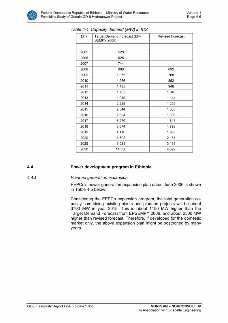
Federal Democratic Republic of Ethiopia – Ministry of Water Resources Volume 1 Feasibility Study of Genale GD-6 Hydropower Project Page 4-6
GD-6 Feaisbility Report Final Volume 1.doc NORPLAN – NORCONSULT JV in Association with Shebelle Engineering
Table 4-4: Capacity demand (MW) in ICS EFY Target Demand Forecast (EP-
SEMPY 2006) Revised Forecast
2005 520 2006 625 2007 744 2008 900 692 2009 1 079 768 2010 1 286 852 2011 1 485 946 2012 1 705 1 040 2013 1 949 1 144 2014 2 229 1 259 2015 2 544 1 385 2016 2 894 1 509 2017 3 270 1 645 2018 3 674 1 793 2019 4 116 1 955 2020 4 602 2 131 2025 8 021 3 189 2030 14 330 4 522
4.4 Power development program in Ethiopia
4.4.1 Planned generation expansion
EEPCo's power generation expansion plan dated June 2006 is shown in Table 4-5 below.
Considering the EEPCo expansion program, the total generation ca-pacity comprising existing plants and planned projects will be about 3700 MW in year 2015. This is about 1150 MW higher than the Target Demand Forecast from EPSEMPY 2006, and about 2300 MW higher than revised forecast. Therefore, if developed for the domestic market only, the above expansion plan might be postponed by many years.
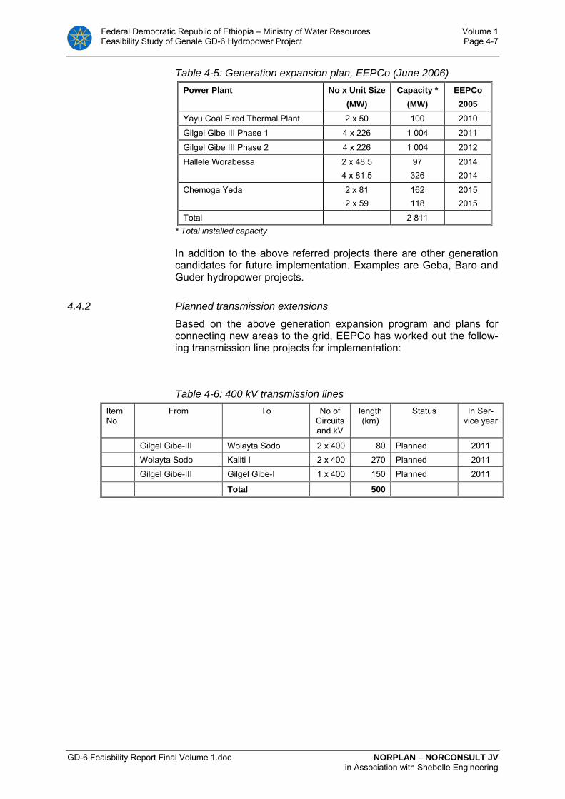
Federal Democratic Republic of Ethiopia – Ministry of Water Resources Volume 1 Feasibility Study of Genale GD-6 Hydropower Project Page 4-7
GD-6 Feaisbility Report Final Volume 1.doc NORPLAN – NORCONSULT JV in Association with Shebelle Engineering
Table 4-5: Generation expansion plan, EEPCo (June 2006) Power Plant No x Unit Size
(MW) Capacity *
(MW) EEPCo
2005 Yayu Coal Fired Thermal Plant 2 x 50 100 2010
Gilgel Gibe III Phase 1 4 x 226 1 004 2011
Gilgel Gibe III Phase 2 4 x 226 1 004 2012
Hallele Worabessa
2 x 48.5 4 x 81.5
97 326
2014 2014
Chemoga Yeda 2 x 81 2 x 59
162 118
2015 2015
Total 2 811 * Total installed capacity
In addition to the above referred projects there are other generation candidates for future implementation. Examples are Geba, Baro and Guder hydropower projects.
4.4.2 Planned transmission extensions
Based on the above generation expansion program and plans for connecting new areas to the grid, EEPCo has worked out the follow-ing transmission line projects for implementation:
Table 4-6: 400 kV transmission lines Item No
From To No of Circuits and kV
length (km)
Status In Ser-vice year
Gilgel Gibe-III Wolayta Sodo 2 x 400 80 Planned 2011 Wolayta Sodo Kaliti I 2 x 400 270 Planned 2011 Gilgel Gibe-III Gilgel Gibe-I 1 x 400 150 Planned 2011
Total 500
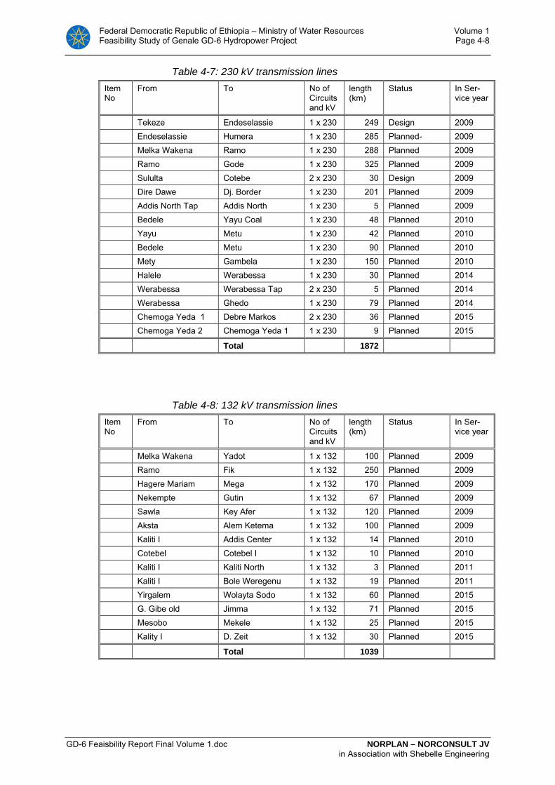
Federal Democratic Republic of Ethiopia – Ministry of Water Resources Volume 1 Feasibility Study of Genale GD-6 Hydropower Project Page 4-8
GD-6 Feaisbility Report Final Volume 1.doc NORPLAN – NORCONSULT JV in Association with Shebelle Engineering
Table 4-7: 230 kV transmission lines Item No
From To No of Circuits and kV
length (km)
Status In Ser-vice year
Tekeze Endeselassie 1 x 230 249 Design 2009 Endeselassie Humera 1 x 230 285 Planned- 2009 Melka Wakena Ramo 1 x 230 288 Planned 2009 Ramo Gode 1 x 230 325 Planned 2009 Sululta Cotebe 2 x 230 30 Design 2009 Dire Dawe Dj. Border 1 x 230 201 Planned 2009 Addis North Tap Addis North 1 x 230 5 Planned 2009 Bedele Yayu Coal 1 x 230 48 Planned 2010 Yayu Metu 1 x 230 42 Planned 2010 Bedele Metu 1 x 230 90 Planned 2010 Mety Gambela 1 x 230 150 Planned 2010 Halele Werabessa 1 x 230 30 Planned 2014 Werabessa Werabessa Tap 2 x 230 5 Planned 2014 Werabessa Ghedo 1 x 230 79 Planned 2014 Chemoga Yeda 1 Debre Markos 2 x 230 36 Planned 2015 Chemoga Yeda 2 Chemoga Yeda 1 1 x 230 9 Planned 2015
Total 1872
Table 4-8: 132 kV transmission lines Item No
From To No of Circuits and kV
length (km)
Status In Ser-vice year
Melka Wakena Yadot 1 x 132 100 Planned 2009 Ramo Fik 1 x 132 250 Planned 2009 Hagere Mariam Mega 1 x 132 170 Planned 2009 Nekempte Gutin 1 x 132 67 Planned 2009 Sawla Key Afer 1 x 132 120 Planned 2009 Aksta Alem Ketema 1 x 132 100 Planned 2009 Kaliti I Addis Center 1 x 132 14 Planned 2010 Cotebel Cotebel I 1 x 132 10 Planned 2010 Kaliti I Kaliti North 1 x 132 3 Planned 2011 Kaliti I Bole Weregenu 1 x 132 19 Planned 2011 Yirgalem Wolayta Sodo 1 x 132 60 Planned 2015 G. Gibe old Jimma 1 x 132 71 Planned 2015 Mesobo Mekele 1 x 132 25 Planned 2015 Kality I D. Zeit 1 x 132 30 Planned 2015
Total 1039
Federal Democratic Republic of Ethiopia – Ministry of Water Resources Volume 1 Feasibility Study of Genale GD-6 Hydropower Project Page 4-9
GD-6 Feaisbility Report Final Volume 1.doc NORPLAN – NORCONSULT JV in Association with Shebelle Engineering
4.4.3 Power market assumptions and study objectives
Genale has a large hydropower potential. The annual growth in elec-tricity demand in Ethiopia is too small to justify implementation of the project on near to medium term. Therefore, if developed early, the project will need to supply power demands in neighbouring countries in addition to the domestic market. The present study investigates the generation potential of the project for export to a large power market outside the country, presumably to Kenya. If economically viable, Genale might theoretically replace thermal power generation projects in Kenya.
The transmission study has investigated how to connect Genale to the domestic grid. It is a precondition for the transmission studies that the export capacity will be sufficient to export all power from Genale. Supply to the domestic market will more or less be limited to reserve supply during severe contingencies in the Ethiopian system.
As part of the optimization studies for the transmission lines, costs were estimated for some different conductor size at 230 kV and 400 kV voltage level as presented in Annex 3 E.
4.4.4 Connection of Genale GD-3 to the grid
According to the Feasibility study for GD-3, this plant was supposed to be connected to the grid through a 290 km long 230 kV double cir-cuit line to Mega substation close to the border to Kenya. From this substation it was assumed a 400 kV double circuit line to the Wolayta Sodo substation and the HVDC interconnector to Kenya.
However, the Feasibility Study of the “Ethiopia - Kenya Power Sys-tems Interconnection Project” preformed by Fitchner has now been completed. This study concludes that the HVDC interconnection Ethiopia - Kenya shall start from Wolayta Sodo instead of Mega. Therefore, there is no need for the 400 kV line from Wolayta Sodo to Mega. Hence it is assumed that GD-3 will be connected to Wolayta Sodo.
Two different electrical design alternatives for connection GD-3 to the grid have been evaluated:
• 230 kV design and connection to Wolayta Sodo
• 400 kV design and connection to Wolayta Sodo
A cost comparison of the two alternatives is presented in Annex 3 E, showing that the total annual cost for the 230 kV alternative, including Investment, O&M and value of losses, is approximately USD 15 mil-lion higher than for the 400 kV alternative.
It is therefore assumed that GD-3 will be connected to Wolayta Sodo through a 400 kV double circuit line.

Federal Democratic Republic of Ethiopia – Ministry of Water Resources Volume 1 Feasibility Study of Genale GD-6 Hydropower Project Page 4-10
GD-6 Feaisbility Report Final Volume 1.doc NORPLAN – NORCONSULT JV in Association with Shebelle Engineering
4.4.5 Connection of GD-6 to GD-3
Assuming that GD-3 is connected to the Grid at 400 kV level, two dif-ferent electrical alternatives for connecting of GD-6 have been evalu-ated:
• 230 kV design and connection to GD-3
• 400 kV design and connection to GD-3
A cost comparison of the two alternatives is presented in Annex 3 E, showing that the total annual cost for the 230 kV alternative, including Investment, O&M and value of losses, is approximately USD 2.5 mil-lion higher than for the 400 kV alternative.
It is therefore recommended to connect GD-6 to GD-3 through a 400 kV single circuit line with 2 x Moose conductor.
4.4.6 Transmission system planning criteria and design aspects
· Reference is made to Annex 3 E for fairly detailed considerations re-garding selection of planning and design criteria.
4.4.7 Transmission cost estimates
Annex 3E contains cost considerations and estimates in connection with optimization studies and in connection with choice between 230 kV and 400 kV alternatives.
For cost estimate of the recommended transmission system with sub-stations, reference is made to Chapter 11.
4.4.8 Power system analyses
Annex 3E contains power system analyses of GD-3 and GD-6 con-nected to the grid. Stability analyses are performed in order to inves-tigate transient stability of the two proposed solutions with 230 kV and 400 kV connection of GD-3 and GD-6. The results show that two double circuit 230 kV lines are needed from GD-3 to Wolayta Sodo in order for GD-3 and GD-6 to remain synchronism for a dimensioning disturbance. GD-6 can be connected to GD-3 through one double cir-cuit 230 kV line.
With connection at 400 kV, one double circuit line from GD-3 to Wolayta Sodo is sufficient in order to maintain synchronism at GD-3 and GD-6 for a dimensioning disturbance. GD-6 can be connected to GD-3 with one single circuit 400 kV line, assumed that the dimension-ing fault in the system is larger that 240 MW.
Due to loading below SIL, shunt reactors are needed in Wolayta Sodo and GD-3 in order to keep the voltages within the limits defined in the grid code.

Federal Democratic Republic of Ethiopia – Ministry of Water Resources Volume 1 Feasibility Study of Genale GD-6 Hydropower Project Page 4-11
GD-6 Feaisbility Report Final Volume 1.doc NORPLAN – NORCONSULT JV in Association with Shebelle Engineering
Figure 4-1: Map of Ethiopian Interconnection System (ICS)
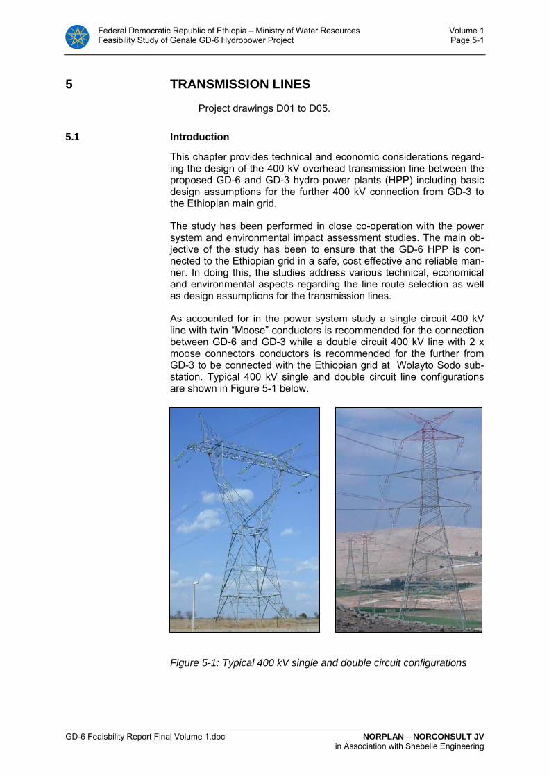
Federal Democratic Republic of Ethiopia – Ministry of Water Resources Volume 1 Feasibility Study of Genale GD-6 Hydropower Project Page 5-1
GD-6 Feaisbility Report Final Volume 1.doc NORPLAN – NORCONSULT JV in Association with Shebelle Engineering
5 TRANSMISSION LINES
Project drawings D01 to D05.
5.1 Introduction
This chapter provides technical and economic considerations regard-ing the design of the 400 kV overhead transmission line between the proposed GD-6 and GD-3 hydro power plants (HPP) including basic design assumptions for the further 400 kV connection from GD-3 to the Ethiopian main grid.
The study has been performed in close co-operation with the power system and environmental impact assessment studies. The main ob-jective of the study has been to ensure that the GD-6 HPP is con-nected to the Ethiopian grid in a safe, cost effective and reliable man-ner. In doing this, the studies address various technical, economical and environmental aspects regarding the line route selection as well as design assumptions for the transmission lines.
As accounted for in the power system study a single circuit 400 kV line with twin “Moose” conductors is recommended for the connection between GD-6 and GD-3 while a double circuit 400 kV line with 2 x moose connectors conductors is recommended for the further from GD-3 to be connected with the Ethiopian grid at Wolayto Sodo sub-station. Typical 400 kV single and double circuit line configurations are shown in Figure 5-1 below.
Figure 5-1: Typical 400 kV single and double circuit configurations
Federal Democratic Republic of Ethiopia – Ministry of Water Resources Volume 1 Feasibility Study of Genale GD-6 Hydropower Project Page 5-2
GD-6 Feaisbility Report Final Volume 1.doc NORPLAN – NORCONSULT JV in Association with Shebelle Engineering
5.2 Transmission Line Routes
5.2.1 Connections to GD-3 HPP
In the Feasibility Study for the Genale (GD-3) Multipurpose Hydro-power Project (Final Report, August 2007) a system voltage of 230 kV was assumed for the transmission connections to GD-3 compris-ing two 230 kV single circuit lines from GD-5 and GD-6 and one out-going 230 kV double circuit line to be connected to the Ethiopian main grid at Mega located approximately 295 km south-west of GD-3
However, as accounted for in the power system analysis the conclu-sion of the recently finalized Feasibility Study for the “Ethiopia - Kenya Power Systems Interconnection Project” to locate the HVDC converter station at Wolayta Sodo instead of Mega has resulted in that GD-3 also is recommended connected to Wolayta Sodo through a 400 kV double circuit line. In consequence, also the lines from GD-5 and GD-6 to GD-3 are recommended designed for a 400 kV system voltage.
The system voltage upgrade requires the switchyard plan as pre-sented in the GD-3 feasibility report to be expanded due to increased insulation requirements. Further it would be recommended to have the switchyard layout rearranged with the two bays for the outgoing double circuit line to Wolayta Sodo moved to the opposite side of the switchyard (west side) in order to avoid the line to be rerouted through several angle structures in a limited area before continuing straight westwards. The arrangement is indicated on the line route map drawing number D01-4 where both the new alignment for the 400 kV line to Wolayo Sodo and the original alignment for the 230 kV line to Mega is plotted.
5.2.2 GD-5 and GD-6 Reservoirs
The reservoirs for the planned GD-5 and GD-6 hydro power plants in-fluence on the proposed alignment for the 400 kV transmission line from GD-6 to GD-3 recommended to follow the Genale valley on the south side of the river. In order to verify sufficient clearance the reser-voirs have conservatively been plotted on the line route maps, draw-ing number T01-1, -2, -3 and -4 based on a water level (HRWL) of 690 metre for GD-5 and 585 metre for GD-6. Where the line run alongside the reservoirs a minimum height clearance from the HRWL to the line RoW (Right of Way) of 20 metre has been applied.
5.2.3 Line route GD-6 to GD-3
The recommended line route as identified for the 400 kV single circuit line from GD-6 to GD-3 has been plotted on topographical maps in scale 1:50,000 as presented on the line route drawings no T01-1, -2, -3 and -4 assuming a RoW width of 40-50 metres depending on the insulator string applications applied.
The line emerges from the GD-6 switchyard located on the hill above the entrance tunnel to the GD-6 underground power station and is lead westwards on the upper side of the planned access road and 33 kV line to the dam site to reach the GD-6 reservoir after app. 5.5 km.
Federal Democratic Republic of Ethiopia – Ministry of Water Resources Volume 1 Feasibility Study of Genale GD-6 Hydropower Project Page 5-3
GD-6 Feaisbility Report Final Volume 1.doc NORPLAN – NORCONSULT JV in Association with Shebelle Engineering
As the line reach the GD-6 dam site the line enters the technically most challenging sections over a distance of app. 20 km where the line is “pushed” uphill due to the GD-6 and GD-5 reservoirs. On this section some alternative alignments have been identified due to the irregularity of the hill formations and local escarpments close to the reservoirs. Although the more straight line sections identified is tech-nically feasible the final line route is recommended subject to a more thorough investigation during the detail design stage in order to verify the mechanical conductor, tower and span capacities to be within ac-ceptable limits.
Having passed the GD-5 reservoir the valley starts to open up result-ing in, with a few exemptions, an easier alignment and from km 58 the line runs straight to reach the GD-3 switchyard at km 76.
Permanent access roads to the RoW is limited to the first and last few kilometres of the line route plus an existing road to a pumping station at Genale river, the road crossing the line at km 35 some 5 km west of the GD-5 reservoir.
Temporary roads during implementation of the project are assumed constructed along the line route. Due to the irregularity in the terrain it is considered not possible to maintain this road within the defined RoW and measures are recommended to be taken in order to limit the environmental impacts in this respect.
The total length of the line has been measured to 76-77 km. How-ever, for cost estimates possible deviations and adjustments during the detail design has been taken into consideration and a total line length of 80 km has been applied accordingly.
5.3 400 kV Single Circuit GD-6 - GD-3 Transmission Line Design
5.3.1 Design standards
It is assumed that the 400 kV transmission line is constructed using International Competitive Bidding (ICB) and that the Contract will be a turn key contract where the detailed design will be the responsibility of the Contractor based on the Employer’s specifications, conceptual drawings and estimated bill of quantities.
It is recommended to use the principles of the International Electro-technical Commission (IEC) 60826 “Loading and strength of over-head transmission lines” as well as European Standard EN 50341-1 “Overhead electrical lines exceeding AC 45 kV”. Reliability level 2 ac-cording to these standards, i.e. loadings with 150 year return period.
5.3.2 Electrical characteristics
Altitude
Although the altitude on sections of the line route reaches close to 1,000 metre above sea level, standard insulation levels are assumed. However, as for the continuing 400 kV double circuit line from GD-3 to Sodo altitudes above 1,000 metre are reached and influence on both the thermal rating and the insulation coordination due to change
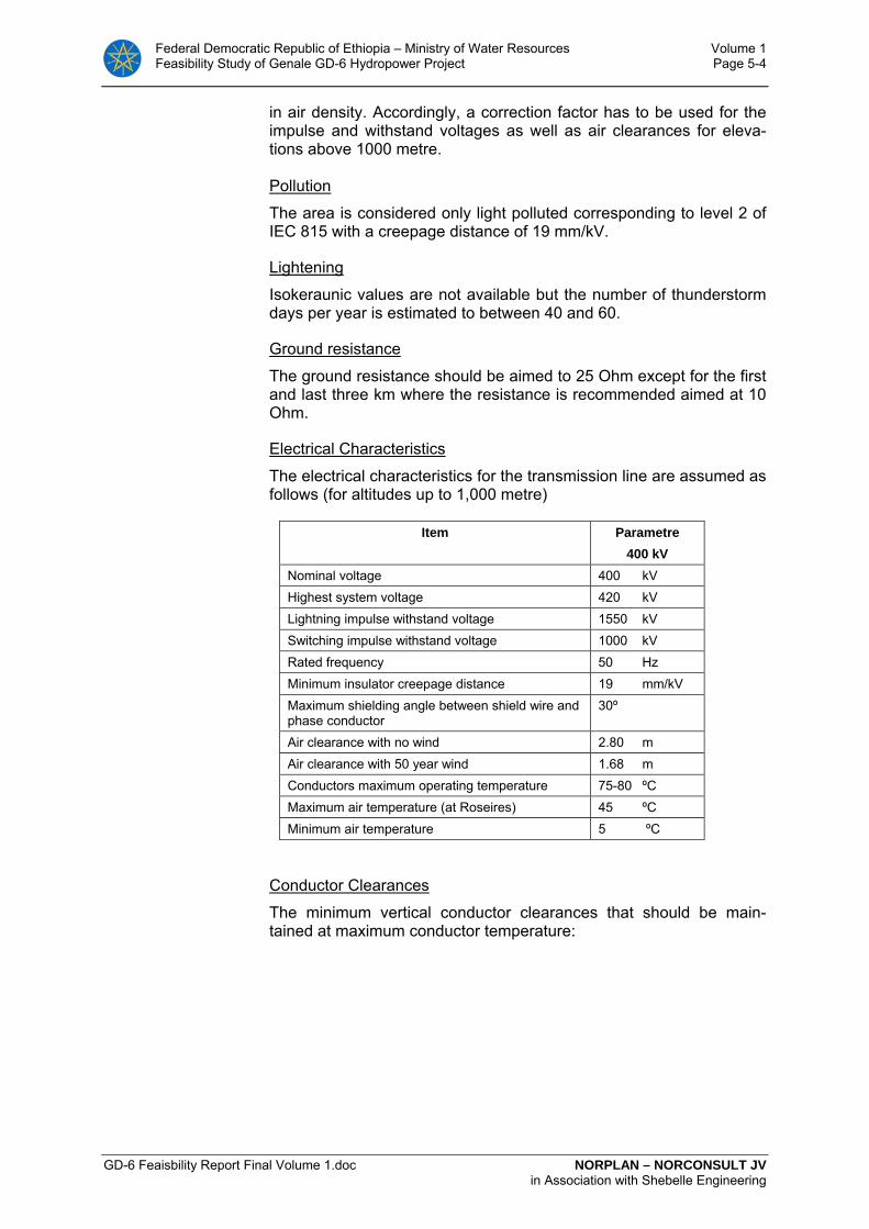
Federal Democratic Republic of Ethiopia – Ministry of Water Resources Volume 1 Feasibility Study of Genale GD-6 Hydropower Project Page 5-4
GD-6 Feaisbility Report Final Volume 1.doc NORPLAN – NORCONSULT JV in Association with Shebelle Engineering
in air density. Accordingly, a correction factor has to be used for the impulse and withstand voltages as well as air clearances for eleva-tions above 1000 metre. Pollution
The area is considered only light polluted corresponding to level 2 of IEC 815 with a creepage distance of 19 mm/kV.
Lightening
Isokeraunic values are not available but the number of thunderstorm days per year is estimated to between 40 and 60.
Ground resistance
The ground resistance should be aimed to 25 Ohm except for the first and last three km where the resistance is recommended aimed at 10 Ohm.
Electrical Characteristics
The electrical characteristics for the transmission line are assumed as follows (for altitudes up to 1,000 metre)
Item Parametre 400 kV
Nominal voltage 400 kV Highest system voltage 420 kV Lightning impulse withstand voltage 1550 kV Switching impulse withstand voltage 1000 kV Rated frequency 50 Hz Minimum insulator creepage distance 19 mm/kV Maximum shielding angle between shield wire and phase conductor
30º
Air clearance with no wind 2.80 m Air clearance with 50 year wind 1.68 m Conductors maximum operating temperature 75-80 ºC Maximum air temperature (at Roseires) 45 ºC Minimum air temperature 5 ºC
Conductor Clearances
The minimum vertical conductor clearances that should be main-tained at maximum conductor temperature:

Federal Democratic Republic of Ethiopia – Ministry of Water Resources Volume 1 Feasibility Study of Genale GD-6 Hydropower Project Page 5-5
GD-6 Feaisbility Report Final Volume 1.doc NORPLAN – NORCONSULT JV in Association with Shebelle Engineering
Item Distance 400 kV
Roads, parking areas etc 9.3 m Normal land 8.3 m Other transmission and distribution lines 4.2 m
Phase Conductors
The following physical properties apply for the selected conductor configuration.
Item 400 kV GB-6 – GB-3
Conductors for each phase 2 x ACSR Moose Cross-section pr. phase 1194.4 mm² Cross-section pr. conductor 597.2 mm² Conductor diameter 31.77 mm Stranding Aluminium 54x3.53 Stranding Steel 7x3.53 Nominal breaking load 161.1 kN Weight without grease 1.999 kg/m Rated d.c resistance at 20 ºC 0.05468 Ω/km
Shield Wires
The 400 kV transmission line should be designed with two overhead shield wires of which one is assumed to be an optical ground wire (OPGW) with at least 12 single modus fibres for communication pur-poses. The OPGW should also be designed to withstand the maxi-mum short circuit current approximately 10 kA with maximum tem-perature 200 ºC. Finished fibre attenuation should be less than 0.40 dB/km at 1310 nm and less than 0.23 at 1550 nm.
The second shield wire is assumed to be a galvanized steel wire or an ACS wire with sufficient nominal breaking load and short circuit capacity.
Vibration Dampers
The phase conductors should be equipped with spacer dampers while normal Stockbridge dampers are assumed for the overhead shield wires.
Insulator Strings
Glass or porcelain insulators according to IEC standards should ap-ply. Double string insulators are recommended for all tension strings while various applications should be evaluated during the detailed design stage for suspension strings where the following configura-tions should be considered:
1. Suspension I-strings on all three phases 2. Suspension I-strings on outer phases and V-string on centre
phase

Federal Democratic Republic of Ethiopia – Ministry of Water Resources Volume 1 Feasibility Study of Genale GD-6 Hydropower Project Page 5-6
GD-6 Feaisbility Report Final Volume 1.doc NORPLAN – NORCONSULT JV in Association with Shebelle Engineering
3. Suspension V-strings on all three phases
The optimisation of tower designs and the corresponding insulator string applications is twofold as the RoW width requirement increase from app. 40 metre with V-strings to app. 50 metre with I-strings. For the specific line it is assumed that land compensation is minimal and further that due to the topography the number of tension towers will be high above normal which would favour I-string applications.
Wind pressure
Relevant meteorological data is not available for the actual area. However, for corresponding projects in the region a maximum wind speed of 34 m/s has been applied and is considered reasonable. The detail design has to evaluate if further investigations are required but insignificant deviations are assumed.
The applied wind speed would result in the following wind loads sub-ject to factored loads according to IEC 60826;
• Wind pressure on structures: 86 kg/m2 • Wind load on conductors: 52 kg/m2 • Wind load on insulators: 60 kg/m2
Tower loadings
Tower loading should be calculated according to IEC 60826 and EN 50341-1. The following loadings should be taken into consideration:
• Wind load at 0 0C applied normal and 45o to structures with a maximum working tension of conductors and shield wires not to exceed 40% of UTS.
• Construction and maintenance loads. • Security loads, broken conductor conditions • Maximum sag at 75 0C in still air
All towers and their related components are assumed to be capable of resisting any combination of the design basic loads multiplied by a factor of safety of 2.0 in normal conditions and 1.25 in broken wire conditions.
Tower Foundations
Conventional steel reinforced concrete foundations are assumed and steel grillage foundations are accordingly not recommended for this type of line. The detail design is assumed subject to soil investiga-tions to be carried out at each tower location by the selected Contrac-tor. The stability of tower foundations shall be designed for the uplift and compression forces in each tower footing as used in the tower design multiplied by an additional safety factor of 1.1.
The connection between tower and foundation shall be by means of stub angles with bolted-on cleats designed to transfer 100% of the leg loads into the main concrete block comprising the foundation. Ac-cordingly adhesion between the stubs and the foundation concrete shall not be considered as transmitting loads to the foundations.

Federal Democratic Republic of Ethiopia – Ministry of Water Resources Volume 1 Feasibility Study of Genale GD-6 Hydropower Project Page 5-7
GD-6 Feaisbility Report Final Volume 1.doc NORPLAN – NORCONSULT JV in Association with Shebelle Engineering
Grounding
All towers should be permanently grounded in order to avoid danger-ous step and touch voltages near towers. The design should be ac-cording to IEEE 80 with the earth wires continuously installed. Spe-cific ground resistance has to be measured before construction work starts, and the individual resistance has to be measured as com-pleted, to verify the calculations. The individual tower footing resis-tance is assumed aimed to be less than 20 Ohm.
Over the first 1.5 km out of any substation or switchyard, all towers, including the terminal towers, should be connected together by con-tinuous counterpoise cable, which also should be connected to the substation / switchyard earthing grid.
5.4 Environmental Mitigation Measures
5.4.1 General
Access and reliability considerations have been primary factors in se-lection of the transmission line route. For environmental reasons the line route is sought to follow as close as possible to roads and tracks as found technically and economically advisable. Within these limita-tions internationally recognised environmental recommendations have been applied when selecting the alignment of the line. It should be noted that the final right-of-way to be established during the de-tailed line survey might deviate from the line route as plotted on the line route map depending on the findings of the detail line survey and soil investigations.
The environmental considerations evaluated when establishing the recommended line route comprise land acquisition, land use, visual impact, electric and magnetic fields impact and impact of construction and maintenance. The extent of these considerations is restricted to issues, which could influence on the technical, economic and envi-ronmental feasibility of the transmission line.
5.4.2 Regulatory Controls, Land Acquisition and Land Use
Regulatory Controls
No areas subjected to regulatory controls have been identified being in conflict with the proposed line route.
Land Acquisition and Land Use
The extent of land acquisition is limited to the tower sites where the line passes through cultivated land and farmland. The fact that farm-ing is based on hand planting and harvesting result in the actual area lost for production is small. Although the total tower base area may be up to 10 x 10 meter the unusable area is limited to the four leg con-crete columns totalling only 5 m2 per tower.
The populated areas along the line is scattered and no households have been identified to be reallocated.
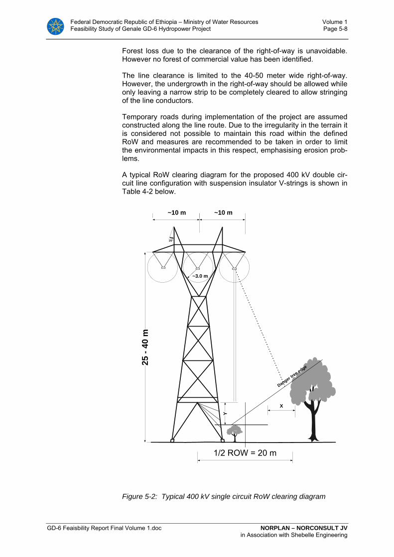
Federal Democratic Republic of Ethiopia – Ministry of Water Resources Volume 1 Feasibility Study of Genale GD-6 Hydropower Project Page 5-8
GD-6 Feaisbility Report Final Volume 1.doc NORPLAN – NORCONSULT JV in Association with Shebelle Engineering
~10 m
~3.0 m
~10 m
1/2 ROW = 20 m
Danger tree edge
Y
X
20°
25 -
40 m
Forest loss due to the clearance of the right-of-way is unavoidable. However no forest of commercial value has been identified.
The line clearance is limited to the 40-50 meter wide right-of-way. However, the undergrowth in the right-of-way should be allowed while only leaving a narrow strip to be completely cleared to allow stringing of the line conductors.
Temporary roads during implementation of the project are assumed constructed along the line route. Due to the irregularity in the terrain it is considered not possible to maintain this road within the defined RoW and measures are recommended to be taken in order to limit the environmental impacts in this respect, emphasising erosion prob-lems.
A typical RoW clearing diagram for the proposed 400 kV double cir-cuit line configuration with suspension insulator V-strings is shown in Table 4-2 below.
Figure 5-2: Typical 400 kV single circuit RoW clearing diagram

Federal Democratic Republic of Ethiopia – Ministry of Water Resources Volume 1 Feasibility Study of Genale GD-6 Hydropower Project Page 5-9
GD-6 Feaisbility Report Final Volume 1.doc NORPLAN – NORCONSULT JV in Association with Shebelle Engineering
5.5 Substations
5.5.1 Genale GD-6
Genale GD-6 switchyard is described in section 3.10. In summary, it contains two bays for cable generator connections and one bay for the outgoing transmission line. Genale GD-6 is assumed to be con-nected to the Genale GD-3 switchyard by a dedicated circuit breaker bay.
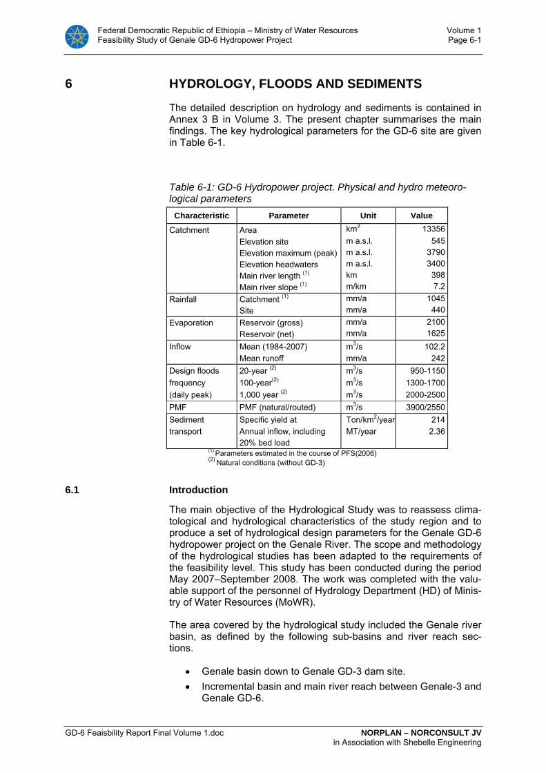
Federal Democratic Republic of Ethiopia – Ministry of Water Resources Volume 1 Feasibility Study of Genale GD-6 Hydropower Project Page 6-1
GD-6 Feaisbility Report Final Volume 1.doc NORPLAN – NORCONSULT JV in Association with Shebelle Engineering
6 HYDROLOGY, FLOODS AND SEDIMENTS
The detailed description on hydrology and sediments is contained in Annex 3 B in Volume 3. The present chapter summarises the main findings. The key hydrological parameters for the GD-6 site are given in Table 6-1.
Table 6-1: GD-6 Hydropower project. Physical and hydro meteoro-logical parameters
Characteristic Parameter Unit Value
Catchment Area km2 13356 Elevation site m a.s.l. 545 Elevation maximum (peak) m a.s.l. 3790 Elevation headwaters m a.s.l. 3400 Main river length (1) km 398 Main river slope (1) m/km 7.2 Rainfall Catchment (1) mm/a 1045 Site mm/a 440 Evaporation Reservoir (gross) mm/a 2100 Reservoir (net) mm/a 1625 Inflow Mean (1984-2007) m3/s 102.2 Mean runoff mm/a 242 Design floods 20-year (2) m3/s 950-1150 frequency 100-year(2) m3/s 1300-1700 (daily peak) 1,000 year (2) m3/s 2000-2500 PMF PMF (natural/routed) m3/s 3900/2550 Sediment Specific yield at Ton/km2/year 214 transport Annual inflow, including MT/year 2.36 20% bed load
(1) Parameters estimated in the course of PFS(2006) (2) Natural conditions (without GD-3)
6.1 Introduction
The main objective of the Hydrological Study was to reassess clima-tological and hydrological characteristics of the study region and to produce a set of hydrological design parameters for the Genale GD-6 hydropower project on the Genale River. The scope and methodology of the hydrological studies has been adapted to the requirements of the feasibility level. This study has been conducted during the period May 2007–September 2008. The work was completed with the valu-able support of the personnel of Hydrology Department (HD) of Minis-try of Water Resources (MoWR).
The area covered by the hydrological study included the Genale river basin, as defined by the following sub-basins and river reach sec-tions.
• Genale basin down to Genale GD-3 dam site. • Incremental basin and main river reach between Genale-3 and
Genale GD-6.

Federal Democratic Republic of Ethiopia – Ministry of Water Resources Volume 1 Feasibility Study of Genale GD-6 Hydropower Project Page 6-2
GD-6 Feaisbility Report Final Volume 1.doc NORPLAN – NORCONSULT JV in Association with Shebelle Engineering
This study was carried out based on the assumption that the up-stream GD-3 project with principal reservoir storage shall be con-structed in advance or parallel to the GD-6, making the reservoir of GD-3 available from the first year of operation.
6.2 Scope of hydrological investigations
The GD-6 Pre-Feasibility Study derived regional climatologic and hy-drologic characteristics of the Genale basin appears reliable. Hence, the main emphasis of the current study was dedicated to:
• Extension up to date of hydrological data sets • Quality assessment and compilation of primary hydrologic
data i.e. water level records and discharge measurements of the key Genale River gauging station at Chenemasa
• Design and execution of a flow and sediment measurement programme at the Chenemasa gauging station
• Re-evaluation of ratings of the Chenemasa hydrometric sta-tion
• Refinement of GD-6 inflow series • Reassessment of design flood estimates
6.3 Genale river basin
The Genale River has a basin area of some 57,500 km2. It constitutes the largest sub-basin within the Genale-Dawa river system. The sys-tem discharges to the Indian Ocean. The Genale River originates from the southern slopes of the Bale Mountains massif in the north-east and from the Sidamo Mountains in the north-west. The GD-6 sub-basin encompasses a relatively small area of some 13,350 km2 of the upper and mid-sections of the Genale basin. The basin has an elongated shape. Its straight line length down to GD-6 site is around 250 km. The width of the basin varies from some 100 km in the upper part to less than 20 km in the vicinity of GD-6 project.
6.4 Hydrological data base
The Hydrology Department of MoWR is responsible for the operation of discharge gauging stations and the collection of river flow data in Ethiopia. There are 11 discharge gauging stations within the Genale basin, see Table 6-2.

Federal Democratic Republic of Ethiopia – Ministry of Water Resources Volume 1 Feasibility Study of Genale GD-6 Hydropower Project Page 6-3
GD-6 Feaisbility Report Final Volume 1.doc NORPLAN – NORCONSULT JV in Association with Shebelle Engineering
Table 6-2: Hydrometric stations in Genale basin Code River Station Name Lat.N Lon.E Area
(km2) Elevation
(m) 2023 Morodo Nr. Bona Kike 6 31 38 41 85.9 2140 2022 Ererte Nr. Bona Kike 6 31 38 41 99.3 2130 2021 Gelana Nr. Bona Kike 6 31 38 44 376 1960 2010 Logita Nr. Bensa Daye 6 30 38 45 729 1900 2014 Bonora Nr. Bensa Daye 6 31 38 48 343 1840 2024 Konkona Nr. Bensa Daye 6 31 38 49 52.3 1880 2025 Gambetu Nr. Aroressa 6 22 38 52 270 1510 2026 U.Genale Nr. Girja 6 12 38 57 3177 1360 2002 Genale At Chenemasa 5 42 39 32 9190 1120 2011 Genale Nr. Kole Bridge 4 26 41 50 56135 198 2001 Genale At Helwei 4 22 41 53 56583 195
The proposed GD-3 and GD-6 projects with respective basin areas of some 10440 km2 and 13350 km2 are located in the mid section of Genale basin. Data collected at the Helwei and the Kole Bridge sta-tions have only limited value for description of hydrology of the project sites. These stations are located some 300 km downstream, and they gauge outflow from a basin more than five times larger than the Genale basin delimited at the GD-6 site.
Of the remaining nine gauging stations, seven are located in the up-per mountainous part of the basin on major tributaries that form the Genale River. These stations are situated more than 200 km up-stream from the GD-3 site. Records of tributaries streamflow are of great value for the description of Genale River flow formation but should only be used as supplementary information for estimation of hydrological parameters of the planned projects.
Only two stations are located on the Genale main river. The upper Genale station near Girja has a basin area of some 3170 km2. Unfor-tunately, this station has not yet been rated. In practise, the only sta-tion in the Genale basin, which supplies data that can be used di-rectly for estimation of hydrology of the proposed hydropower pro-jects, is the Chenemasa gauging station.
6.5 Flow series
In the course of the present study the Genale daily flow series were updated up to 2007. Initially the revised rating equations were used to re-generate daily flow series at base station. This allowed compiling the series of observed flows at Chenemasa for the period from 1973 to 2007. However due to the dubious quality of Chenemasa stream-flows for period 1973-1983, as the basis for derivation of inflow series to reservoirs at the GD-3 and GD-6 dam sites, the 1984-2007 series were used. The salient statistics of the series derived in the course of this study and the prefeasibility series are given in Table 6-3. Monthly discharge values of the established series are given in Annex 3B.

Federal Democratic Republic of Ethiopia – Ministry of Water Resources Volume 1 Feasibility Study of Genale GD-6 Hydropower Project Page 6-4
GD-6 Feaisbility Report Final Volume 1.doc NORPLAN – NORCONSULT JV in Association with Shebelle Engineering
Table 6-3: Statistical parameters of mean annual series of discharge at Chenemasa discharge station
NORPLAN (1973-2007)
NORPLAN (1984-2007)
Lahmeyer (1973-2004)
Mean annual flow (m3/s) 89.0 92.2 89.2 Mean annual flow (mm) 305 316.0 306.0 Min. annual flow (m3/s) 54.9 54.9 57.0 Max. annual flow (m3/s) 128.2 128.2 134.4 Coefficient of variation (CV) 0.209 0.217 0.219
Transposition of the Chenemasa flow series to the project sites was
carried out with help of runoff-elevation relationships derived for the Genale mainstream basin. The resulting monthly mean flow values of the derived series for the GD-3 and GD-6 sites are given in Table 6-4. The tabulated inflow series, including monthly mean and annual sta-tistics, for the project sites are presented in attachments to the hy-drology report.
Table 6-4: Monthly mean inflow (m3/s), Genale-3 and Genale-6 pro-ject sites (1984-2007)
Chenemasa
(m3/s) GD-3 (m3/s)
GD-6 (m3/s)
Basin area (km2) 9190 10445 13356 Jan 30.2 31.4 33.5 Feb 23.0 23.9 25.6 Mar 22.5 23.4 25.0 Apr 55.2 57.4 61.2 May 105.0 109.2 116.5 Jun 97.3 101.2 108.0 Jul 113.9 118.5 126.5 Aug 154.2 160.3 171.1 Sep 158.1 164.5 175.5 Oct 193.7 201.5 215.0 Nov 104.2 108.4 115.7 Dec 44.4 46.2 49.3
Year 92.2 95.8 102.3 Annual runoff (mm) 316 289 242
6.6 Flood Study
In the Genale basin, the application of the classical approach to flood frequency analysis is to some degree hampered by insufficient amount of required data. Flood frequency analysis has therefore been carried by a Station-year approach. The area-transposition factors were applied to convert the Chenemasa peak flood values to equiva-lent peak flood values at the Genale. Due to uncertainty of the flood frequency estimates and possible bias, the design floods for particu-lar projects are described in terms of a range of expected peak flood values rather than as a single value.

Federal Democratic Republic of Ethiopia – Ministry of Water Resources Volume 1 Feasibility Study of Genale GD-6 Hydropower Project Page 6-5
GD-6 Feaisbility Report Final Volume 1.doc NORPLAN – NORCONSULT JV in Association with Shebelle Engineering
Table 6-5: Daily flood peak values for different return periods at the selected projects sites (natural floods)
Project site
Return pe-riod T (years)
10 20 50 100 1000
GD-3 dam 750-850 850-1050 1050-1250 1200-1500 1800-2200
GD-6 dam 850-950 950-1150 1200-1400 1300-1700 2000-2500
Design flood hydrographs at the project sites were simulated with help of the HEC-HMS model. The Probable Maximum Flood is usu-ally defined as a flood that may be expected from the the most severe combination of critical meteorological and hydrologic conditions that are reasonably possible in the drainage basin under study. Hereby, the team ran the HEC simulation for three different scenarios:
1. A stand-alone scenario; considering the PMF at GD-6 site as an independent event from the upstream reservoir storage.
2. A cascade scenario; when the PMF at GD-6 site would be af-fected in normal operating circumstances by the operation of the GD-3 reservoir. This reservoir would offer a substantial degree of flood retention, attenuation and delay.
3. A cascade scenario-“worst case”. For this scenario, we used the same model setup as in the case 2, but due to the large size of the basin, it was assumed that the PMP event is not concomitant over the entire basin. Particularly the flood hy-drograph in the GD-6 incremental basin was generated from the PMF event starting three days after the beginning of the event used in the remaining four sub-basins.
Table 6-6 presents peak flow values at sub-basins control points and the resulting PMF peak discharge at GD-6 site for all three modelling scenarios. The generated PMF hydrographs at the Genale pro-ject sites, including also the GD-3 reservoir and GD-3 to GD-6 channel routing procedure, are shown in Figure 6-1.

Federal Democratic Republic of Ethiopia – Ministry of Water Resources Volume 1 Feasibility Study of Genale GD-6 Hydropower Project Page 6-6
GD-6 Feaisbility Report Final Volume 1.doc NORPLAN – NORCONSULT JV in Association with Shebelle Engineering
Table 6-6: Probable Maximum Flood. Outcome of HEC-HMS simula-tion procedure
Gd-6 basin element Flow control Peak (m3/s)
Time (h)
Peak (m3/s)
Time (h)
Peak (m3/s)
Time (h)
Scenario 1 2 3 Upper Genale outflow 1710 84 " " " " Geberticha outflow 1380 75 " " " " Geberticha -Iya reach Inflow 2860 78 " " " " Geberticha -Iya reach outflow (routing) 2835 81 " " " " Iya Outflow 1055 72 " " " " Iya - GD-3 site reach Inflow 3600 78 " " " " Iya - GD-3 site reach outflow (routing) 3020 90 " " " " Incremental GD-3 Outflow 1175 75 " " " " GD-3 reservoir Inflow 3740 87 " " " " GD-3 reservoir Outflow 3740 87 1345 135 " " GD-3 to GD-6 river reach Inflow 3740 87 1345 135 " "
GD-3 to GD-6 river reach outflow (routing) 3190 99 1315 153 " "
Incremental GD-6 outflow 1450 78 1450 78 1450 126 GD-6 reservoir Inflow 3900 96 1590 144 2590 126
Inspection of Table 6-6 shows that depending on the modelling sce-nario the calculated values of PMF at GD-6 reservoir site vary from 3900 m3/s for natural PMF to 1590 m3/s for the scenario with opera-tional GD-3 reservoir and simultaneous PMP event over the entire GD-6 basin. The third scenario with the PMP peak rainfall over the GD-6 incremental basin delayed by three days yielded the PMF of 2590 m3/s.
No single method of PMF analysis is without limitations. The relatively large size of the GD-6 basin (more than 13,000 km2) and limited amount of rainfall and flow data makes the PMF estimation somehow difficult and subjective. So many parameters define the basin charac-teristics and hydraulics of runoff that the hydrologic engineer will al-ways need to rely on experience and good judgment. It is the con-sultant opinion that for the design purpose of GD-6 outflow structures a conservative PMF value of 2500 m3/s should be used.
The flood analysis was completed by applying the HEC-HMS model to generate design flood hydrographs with return period of 1000 years. The 1000-years maximum daily rainfall frequency values from Hagere Salem and Negele were used for analysis. The same concep-tual setup and parameterization of HEC-HMS model was used as in the case PMF derivation. Information about simulated 1000-years peak values at the GD-6 site is given in Table 6-7 The hydrographs are tabulated in Attachment 3.
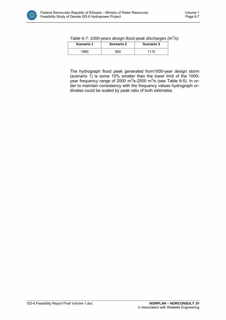
Federal Democratic Republic of Ethiopia – Ministry of Water Resources Volume 1 Feasibility Study of Genale GD-6 Hydropower Project Page 6-7
GD-6 Feaisbility Report Final Volume 1.doc NORPLAN – NORCONSULT JV in Association with Shebelle Engineering
Table 6-7: 1000-years design flood peak discharges (m3/s) Scenario 1 Scenario 2 Scenario 3
1880 850 1110
The hydrograph flood peak generated from1000-year design storm (scenario 1) is some 10% smaller than the lower limit of the 1000-year frequency range of 2000 m3/s-2500 m3/s (see Table 6-5). In or-der to maintain consistency with the frequency values hydrograph or-dinates could be scaled by peak ratio of both estimates.
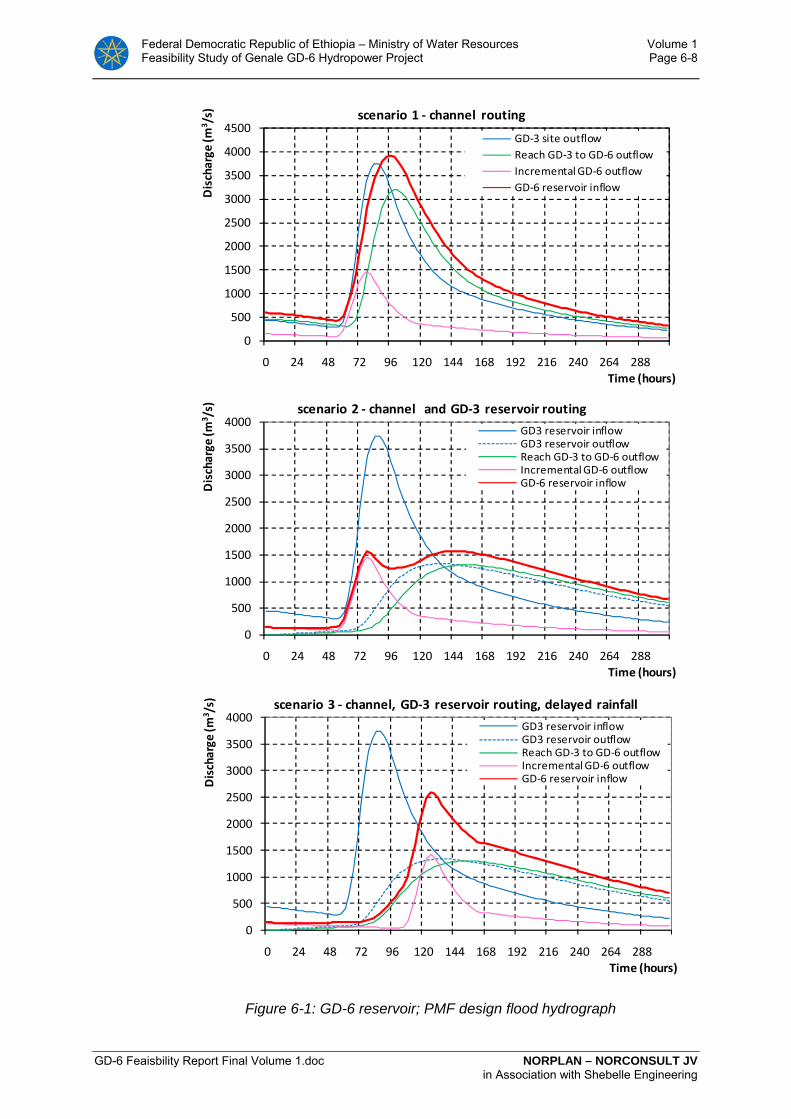
Federal Democratic Republic of Ethiopia – Ministry of Water Resources Volume 1 Feasibility Study of Genale GD-6 Hydropower Project Page 6-8
GD-6 Feaisbility Report Final Volume 1.doc NORPLAN – NORCONSULT JV in Association with Shebelle Engineering
0
500
1000
1500
2000
2500
3000
3500
4000
4500
0 24 48 72 96 120 144 168 192 216 240 264 288
Discharge
(m3 /s)
Time (hours)
scenario 1 ‐ channel routing
GD‐3 site outflowReach GD‐3 to GD‐6 outflowIncremental GD‐6 outflowGD‐6 reservoir inflow
0
500
1000
1500
2000
2500
3000
3500
4000
0 24 48 72 96 120 144 168 192 216 240 264 288
Discharge
(m3 /s)
Time (hours)
scenario 2 ‐ channel and GD‐3 reservoir routing
GD3 reservoir inflowGD3 reservoir outflowReach GD‐3 to GD‐6 outflowIncremental GD‐6 outflowGD‐6 reservoir inflow
0
500
1000
1500
2000
2500
3000
3500
4000
0 24 48 72 96 120 144 168 192 216 240 264 288
Discharge
(m3 /s)
Time (hours)
scenario 3 ‐ channel, GD‐3 reservoir routing, delayed rainfall
GD3 reservoir inflowGD3 reservoir outflowReach GD‐3 to GD‐6 outflowIncremental GD‐6 outflowGD‐6 reservoir inflow
Figure 6-1: GD-6 reservoir; PMF design flood hydrograph
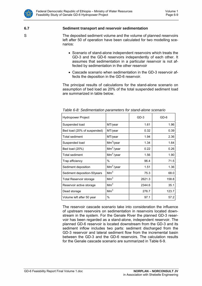
Federal Democratic Republic of Ethiopia – Ministry of Water Resources Volume 1 Feasibility Study of Genale GD-6 Hydropower Project Page 6-9
GD-6 Feaisbility Report Final Volume 1.doc NORPLAN – NORCONSULT JV in Association with Shebelle Engineering
6.7 Sediment transport and reservoir sedimentation
S The deposited sediment volume and the volume of planned reservoirs left after 50 of operation have been calculated for two modelling sce-narios:
• Scenario of stand-alone independent reservoirs which treats the GD-3 and the GD-6 reservoirs independently of each other. It assumes that sedimentation in a particular reservoir is not af-fected by sedimentation in the other reservoir
• Cascade scenario when sedimentation in the GD-3 reservoir af-fects the deposition in the GD-6 reservoir.
The principal results of calculations for the stand-alone scenario on assumption of bed load as 20% of the total suspended sediment load are summarized in table below.
Table 6-8: Sedimentation parameters for stand-alone scenario
Hydropower Project GD-3 GD-6
Suspended load MT/year 1.61 1.96
Bed load (20% of suspended) MT/year 0.32 0.39
Total sediment MT/year 1.94 2.36
Suspended load Mm3/year 1.34 1.64
Bed load (20%) Mm3 /year 0.22 0.26
Total sediment Mm3 /year 1.56 1.90
Trap efficiency % 96.4 71.5
Sediment deposition Mm3 /year 1.51 1.36
Sediment deposition-50years Mm3 75.3 68.0
Total Reservoir storage Mm3 2621.3 158.8
Reservoir active storage Mm3 2344.6 35.1
Dead storage Mm3 276.7 123.7
Volume left after 50 year % 97.1 57.2
The reservoir cascade scenario take into consideration the influence of upstream reservoirs on sedimentation in reservoirs located down-stream in the system. For the Genale River the planned GD-3 reser-voir has been regarded as a stand-alone, independent reservoir. The planned GD-6 reservoir is located downstream from the GD-3 and its sediment inflow includes two parts: sediment discharged from the GD-3 reservoir and lateral sediment flow from the incremental basin between the GD-3 and the GD-6 reservoirs. The calculation results for the Genale cascade scenario are summarized in Table 6-9.

Federal Democratic Republic of Ethiopia – Ministry of Water Resources Volume 1 Feasibility Study of Genale GD-6 Hydropower Project Page 6-10
GD-6 Feaisbility Report Final Volume 1.doc NORPLAN – NORCONSULT JV in Association with Shebelle Engineering
Table 6-9: Sedimentation parameters for cascade scenario Hydropower Project GD-6
Outflow of suspended load from GD-3 MT/year 0.068
Inflow of sediment from incremental basin MT/year 0.351
Total suspended sediment MT/year 0.419
Bed load (20% of suspended) MT/year 0.084
Total inflow of sediment MT/year 0.503
Total suspended load Mm3/year 0.349
Bed load (20%) Mm3 /year 0.056
Total sediment inflow Mm3 /year 0.405
Trap efficiency % 71.4
Sediment deposition Mm3 /year 0.289
Sediment deposition-50years Mm3 14.459
Total Reservoir storage Mm3 158.8
Reservoir active storage Mm3 35.1
Dead storage Mm3 123.7
Volume left after 50 year % 90.9%
Federal Democratic Republic of Ethiopia – Ministry of Water Resources Volume 1 Feasibility Study of Genale GD-6 Hydropower Project Page 7-1
GD-6 Feaisbility Report Final Volume 1.doc NORPLAN – NORCONSULT JV Association with Shebelle Engineering
7 GEOLOGY, GROUND CONDITIONS AND CON-STRUCTION MATERIALS
Project drawings E01 to E06 and E-14 Volume 4 with Annexes 4 A – 4 F
7.1 Project geology
Following information is based on geological mapping conducted for the Feasibility study, with support in the publication Memoir 11, Ethio-pian Institute of Geological Surveys - GEOLOGY OF THE NEGELE AREA, with Geological map Negele, 1:250.000, 1998.
In the area of concern, Precambrian biotite gneiss of the Alghe Group is exposed along the Genale river and overlain by Jurassic-Cretaceous sedimentary formations.
The Precambrian rocks vary in lithology. In some areas these rocks are without the banding or pronounced foliation which is typical for gneiss. Intrusive rocks of mafic composition also occur, especially in the area of the Tailrace tunnel. Degree of weathering in Precambrian rocks is assumed variable, also the degree of fracturing and faulting. In some areas, especially in the area of the headrace tunnel, the rock may be more or less without fractures. The general impression is that degree of fracturing is low, but in some areas pronounced fracturing and faulting was observed. Faults have been identified both in the field and on aerial photographs, apparently with a concentration in the area of the Tailrace tunnel.
The Jurassic-Cretaceous formations Jerder Limestones and Melmel limestones are deposited on top of the Precambrian basement rocks. Jerder Limestones comprise mudstones, fossil reef limestones to wackstones, black shales, dolomitic wackstones, pelletal grainstones and sandstones. Map Negele shows presence of gypsum in the Jerder Limestones. Sites of extensive fossil reef limestones (bioher-mes) are found within the project area. The fossile reef limestones are impressive structureless masses of unevenly textured, moundlike porous rocks, built exclusively of biohermes and highly dolomitized. They belong to the sequence of Jerder Limestones.
Melmel Limestones are informed to comprise pelletal oolitic lime-stones, mudstones, alternating beds of wackstones, packstones, and packstones to grainstones, conglomerates and chalky limestones.
The width of the exposed gneiss belt along the Genale River shown on Geological map Negele decreases from in the order of 5km at about 75km upstream of the proposed power house site, to in the or-der of 0.5km at the power house site. This indicates that the gradient of the boundary along the river is somewhat higher than the terrain gradient. Along the about 16 km distance in E-W direction, from in-take to outlet, the boundary declines about 200 m, see Figure 7-1. With the suggested project layout, both water ways and powerhouse are situated in the Precambrian basement rocks, well below the boundary.

Federal Democratic Republic of Ethiopia – Ministry of Water Resources Volume 1 Feasibility Study of Genale GD-6 Hydropower Project Page 7-2
GD-6 Feaisbility Report Final Volume 1.doc NORPLAN – NORCONSULT JV Association with Shebelle Engineering
Figure 7-1: East – west section with projection of boundary between the Precambrian basement rock and overlying Jurassic-Cretaceous sedimentary rocks, and of tunnel system.
For detailed description of the project geology is referred to Feasibility Report Volume 4
7.2 Site study and investigations
7.2.1 Aim and strategy for site investigations
The general idea has been to address important geotechnical issues necessary to demonstrate, to a Feasibility study level, the technical and economic feasibility of developing the scheme, with sufficient level of investigations. Initially all relevant information from previous studies of the project area was reviewed and analysed. A critical analysis of sufficiency and quality of information was done, related to the actual construction works, where ground conditions may be criti-cal for the design.
Based on the available, existing information, a “ground conditions ex-pectation model” was developed, see Volume 4, considering how the various construction parts are affected by the character of the ground. In this process, key problems were defined, also potential lack of in-formation in relation to Feasibility evaluations and design of the pro-ject. A “ground conditions expectation model” is a prediction obtained by evaluating and analysing the available geological information and placing them in relationship to the project conditions and demands
Federal Democratic Republic of Ethiopia – Ministry of Water Resources Volume 1 Feasibility Study of Genale GD-6 Hydropower Project Page 7-3
GD-6 Feaisbility Report Final Volume 1.doc NORPLAN – NORCONSULT JV Association with Shebelle Engineering
specified in the formulation of the ground conditions issues. An ex-pectation model is “problem oriented” and available information is structured so that the most important physical conditions (of technical or economic significance for the project) are analysed.
In regard to dam foundations, conditions of importance are the thick-ness and character of soil overburden, topography and character of bedrock, as well as occurrence of potential leakage channels, like high-permeability weakness zones. One consideration is to conclude on necessary excavation depth for the foundation. Another considera-tion is to define the effect of leakage zones, and to conclude on po-tential remedial measures. Of importance is also the availability of construction materials.
For tunnels, considerations are suitable location of tunnel portals, suf-ficient rock cover along the tunnel, tunnelling properties, stability con-ditions and permeability conditions. These aspects are of importance for the layout / design and for the cost, and if ground conditions are found unsatisfactory for the tentative layout, modifications are needed.
Information on ground conditions has been obtained by various methods, including aerial photo interpretation, geological mapping, and exploratory rotary core drilling. In situ permeability tests were conducted in core drilled boreholes. A number of laboratory tests were conducted on selected rock samples.
7.2.2 Geological mapping
A main concern in the Feasibility study geological mapping has been to properly map the boundary between the Precambrian basement rock and the overlying Jurassic-Cretaceous sedimentary rocks. Ac-cessible locations where the boundary could be observed were identi-fied by use of GPS waypoints. Results from this mapping are pre-sented in Feasibility Report Volume 4 and Annex 4A in Volume 4
7.2.3 Exploratory core drillings
The final program for geotechnical investigations had to be signifi-cantly reduced because of budget reasons. The access to the project area and especially the site for drillings is difficult. Most of the drill sites required helicopter to position the drilling rig and transport all necessary equipment. The final budget for the investigations allowed for drilling of 5 bore holes only. The position of boreholes were care-fully selected in order to get best possible cost-benefit out the avail-able budget.
Site investigations included 5 core drilled boreholes with a total length of about 245m, including permeability assessment by falling head testing and packer testing. 4 of the boreholes were drilled for investi-gation of dam sites (FS-1 and FS-2), while a 70 m deep hole was drilled in a depression downstream of the planned powerhouse loca-tion.
Rock core samples were selected for laboratory testing and petro-graphic analyses. For description of rock conditions encountered in

Federal Democratic Republic of Ethiopia – Ministry of Water Resources Volume 1 Feasibility Study of Genale GD-6 Hydropower Project Page 7-4
GD-6 Feaisbility Report Final Volume 1.doc NORPLAN – NORCONSULT JV Association with Shebelle Engineering
the boreholes and the results of the laboratory testing is referred to Feasibility Report Volume 4 and Annex 4A in Volume 4
7.2.4 Exploratory rotary core drilling
The main objective of core drillings at the dam sites was to collect core samples of the materials for assessment of lithological variation and rock mass quality and variation in permeability conditions. Infor-mation on variation in rock strength was obtained by laboratory test-ing of selected rock samples and information on variation in perme-ability conditions by packer testing in the bore holes.
Exploratory core drillings are listed in Table 7-1. Their locations are shown in location Figure 7-2 and Figure 7-3.
Table 7-1: Rotary core drillings. BORE HOLE
COORDINATES (GPS) ELEVATION, m asl
(by GPS)
Plunge / azimuth, °
DEPTH DRILLEDm EAST NORTH
BH-1 646511 594442 595 90 / - 54.00
BH-2 646638 594231 590 90 / - 58.55
BH-3 647174 594110 600 90 / - 31.55
BH-4 647391 595114 591 90 / - 30.02
BH-6 652633 593999 520 65 / 252 70.35
Total 244.5
Figure 7-2: Location of bore holes at the potential dam sites FS-1 and FS-2
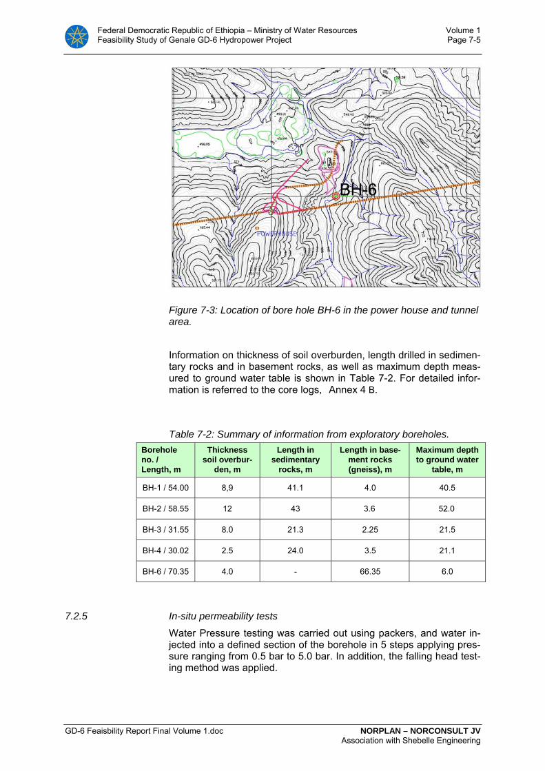
Federal Democratic Republic of Ethiopia – Ministry of Water Resources Volume 1 Feasibility Study of Genale GD-6 Hydropower Project Page 7-5
GD-6 Feaisbility Report Final Volume 1.doc NORPLAN – NORCONSULT JV Association with Shebelle Engineering
Figure 7-3: Location of bore hole BH-6 in the power house and tunnel area.
Information on thickness of soil overburden, length drilled in sedimen-tary rocks and in basement rocks, as well as maximum depth meas-ured to ground water table is shown in Table 7-2. For detailed infor-mation is referred to the core logs, Annex 4 B.
Table 7-2: Summary of information from exploratory boreholes. Borehole no. / Length, m
Thickness soil overbur-
den, m
Length in sedimentary
rocks, m
Length in base-ment rocks (gneiss), m
Maximum depth to ground water
table, m
BH-1 / 54.00 8,9 41.1 4.0 40.5
BH-2 / 58.55 12 43 3.6 52.0
BH-3 / 31.55 8.0 21.3 2.25 21.5
BH-4 / 30.02 2.5 24.0 3.5 21.1
BH-6 / 70.35 4.0 - 66.35 6.0
7.2.5 In-situ permeability tests
Water Pressure testing was carried out using packers, and water in-jected into a defined section of the borehole in 5 steps applying pres-sure ranging from 0.5 bar to 5.0 bar. In addition, the falling head test-ing method was applied.
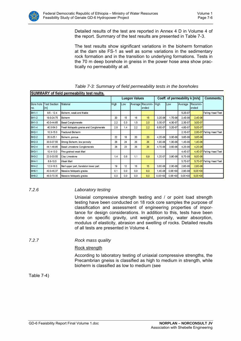
Federal Democratic Republic of Ethiopia – Ministry of Water Resources Volume 1 Feasibility Study of Genale GD-6 Hydropower Project Page 7-6
GD-6 Feaisbility Report Final Volume 1.doc NORPLAN – NORCONSULT JV Association with Shebelle Engineering
Detailed results of the test are reported in Annex 4 D in Volume 4 of the report. Summary of the test results are presented in Table 7-3.
The test results show significant variations in the bioherm formation at the dam site FS-1 as well as some variations in the sedimentary rock formation and in the transition to underlying formations. Tests in the 70 m deep borehole in gneiss in the power hose area show prac-tically no permeability at all.
Table 7-3: Summary of field permeability tests in the boreholes
7.2.6 Laboratory testing
Uniaxial compressive strength testing and / or point load strength testing have been conducted on 18 rock core samples the purpose of classification and assessment of engineering properties of impor-tance for design considerations. In addition to this, tests have been done on specific gravity, unit weight, porosity, water absorption, modulus of elasticity, abrasion and swelling of rocks. Detailed results of all tests are presented in Volume 4.
7.2.7 Rock mass quality
Rock strength
According to laboratory testing of uniaxial compressive strengths, the Precambrian gneiss is classified as high to medium in strength, while bioherm is classified as low to medium (see
Table 7-4)

Federal Democratic Republic of Ethiopia – Ministry of Water Resources Volume 1 Feasibility Study of Genale GD-6 Hydropower Project Page 7-7
GD-6 Feaisbility Report Final Volume 1.doc NORPLAN – NORCONSULT JV Association with Shebelle Engineering
Table 7-4: Uniaxial compressive strength testing of gneiss and of bio-herm
Type of rock UCS, MPa ISRM Classifi-cation
Gneiss 21.2 48.5 32.6 56.6 55.9 55.9 57.0 63.7 30.2
Medium Medium Medium High High High High High Medium
Bioherm 21.5 7.2
11.0 9.1 4.9
22.7
Medium Low Low Low Low Medium
Rock mass classification
For assessment of rock support needs in a tunnel project, a normal procedure is to define the variation in quality of the rock mass. Such classification of rock mass quality is then related to the stability condi-tions in regard to tunnelling. One commonly used classification sys-tem is the NGI-Q system. In this, the physical properties of the rock mass, the ground water behaviour and the rock stress situation are input parameters used for establishing the rock mass quality. Realis-tic conclusions in regard to rock support prediction are depending on reliable input parameters for the rock-mass classification. Reliable in-put parameters are again depending on observations or test results of sufficient quantity and quality.
The Genale tunnels are expected to be entirely located within the Precambrian basement rock, see Figure 7-1. Even with the limited in-formation from core drillings within the basement formation, there is reason to expect in general fair to good stability conditions for the tunnels. A tentative rock mass classification has been done, see chapter 7.2.7. On basis of information from rock exposures along the Genale river and from exploratory drillings, some ideas about varia-tion in rock quality are obtained. and have been used as basis for a highly tentative assessment of rock support needs, see Table 7-5. This distribution is comparable, or with slightly better than the quality distribution suggested In the Pre-feasibility report (35% good, 55% fair and 10% poor, see Table 7-5.
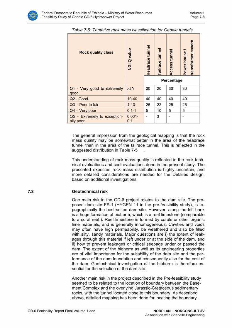
Federal Democratic Republic of Ethiopia – Ministry of Water Resources Volume 1 Feasibility Study of Genale GD-6 Hydropower Project Page 7-8
GD-6 Feaisbility Report Final Volume 1.doc NORPLAN – NORCONSULT JV Association with Shebelle Engineering
Table 7-5: Tentative rock mass classification for Genale tunnels
Rock quality class
NG
I Q v
alue
Hea
drac
e tu
nnel
Tailr
ace
tunn
el
Acc
ess
tunn
el
Pow
er h
ouse
/
tran
sfor
mer
cav
ern
Percentage
Q1 - Very good to extremely good
≥40 30 20 30 30
Q2 - Good 10-40 40 40 40 40 Q3 – Poor to fair 1-10 25 22 25 25 Q4 – Very poor 0.1-1 5 10 5 5 Q5 – Extremely to exception-ally poor
0.001-0.1
- 3 - -
The general impression from the geological mapping is that the rock mass quality may be somewhat better in the area of the headrace tunnel than in the area of the tailrace tunnel. This is reflected in the suggested distribution in Table 7-5 .
This understanding of rock mass quality is reflected in the rock tech-nical evaluations and cost evaluations done in the present study. The presented expected rock mass distribution is highly uncertain, and more detailed considerations are needed for the Detailed design, based on additional investigations.
7.3 Geotechnical risk
One main risk in the GD-6 project relates to the dam site. The pro-posed dam site FS-1 (HYGEN 11 in the pre-feasibility study), is to-pographically the best-suited dam site. However, along the left bank is a huge formation of bioherm, which is a reef limestone (comparable to a coral reef.). Reef limestone is formed by corals or other organic lime materials, and is generally inhomogeneous. Cavities and voids may often have high permeability, be weathered and also be filled with silty, sandy materials. Major questions are i) the extent of leak-ages through this material if left under or at the side of the dam, and ii) how to prevent leakages or critical seepage under or passed the dam. The extent of the bioherm as well as its engineering properties are of vital importance for the suitability of the dam site and the per-formance of the dam foundation and consequently also for the cost of the dam. Geotechnical investigation of the bioherm is therefore es-sential for the selection of the dam site.
Another main risk in the project described in the Pre-feasibility study seemed to be related to the location of boundary between the Base-ment Complex and the overlying Jurassic-Cretaceous sedimentary rocks, with the tunnel located close to this boundary. As described above, detailed mapping has been done for locating the boundary.
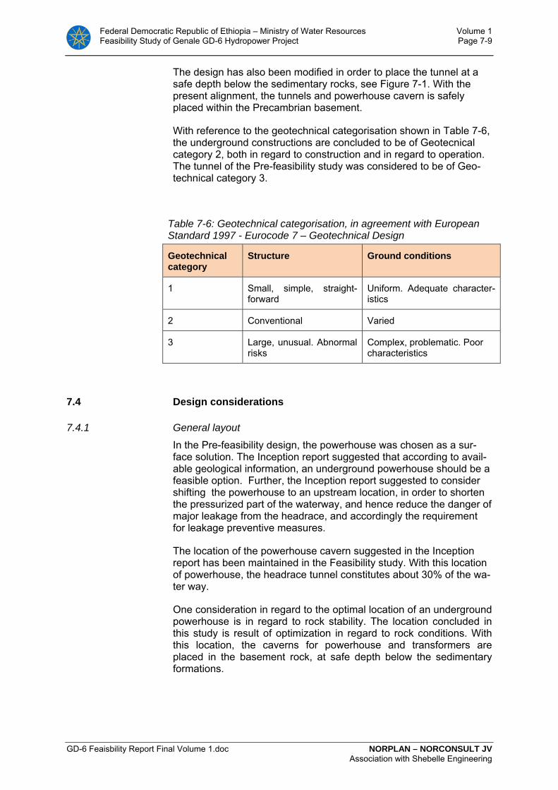
Federal Democratic Republic of Ethiopia – Ministry of Water Resources Volume 1 Feasibility Study of Genale GD-6 Hydropower Project Page 7-9
GD-6 Feaisbility Report Final Volume 1.doc NORPLAN – NORCONSULT JV Association with Shebelle Engineering
The design has also been modified in order to place the tunnel at a safe depth below the sedimentary rocks, see Figure 7-1. With the present alignment, the tunnels and powerhouse cavern is safely placed within the Precambrian basement.
With reference to the geotechnical categorisation shown in Table 7-6, the underground constructions are concluded to be of Geotecnical category 2, both in regard to construction and in regard to operation. The tunnel of the Pre-feasibility study was considered to be of Geo-technical category 3.
Table 7-6: Geotechnical categorisation, in agreement with European Standard 1997 - Eurocode 7 – Geotechnical Design
Geotechnical category
Structure Ground conditions
1 Small, simple, straight-forward
Uniform. Adequate character-istics
2 Conventional Varied
3 Large, unusual. Abnormal risks
Complex, problematic. Poor characteristics
7.4 Design considerations
7.4.1 General layout
In the Pre-feasibility design, the powerhouse was chosen as a sur-face solution. The Inception report suggested that according to avail-able geological information, an underground powerhouse should be a feasible option. Further, the Inception report suggested to consider shifting the powerhouse to an upstream location, in order to shorten the pressurized part of the waterway, and hence reduce the danger of major leakage from the headrace, and accordingly the requirement for leakage preventive measures.
The location of the powerhouse cavern suggested in the Inception report has been maintained in the Feasibility study. With this location of powerhouse, the headrace tunnel constitutes about 30% of the wa-ter way.
One consideration in regard to the optimal location of an underground powerhouse is in regard to rock stability. The location concluded in this study is result of optimization in regard to rock conditions. With this location, the caverns for powerhouse and transformers are placed in the basement rock, at safe depth below the sedimentary formations.

Federal Democratic Republic of Ethiopia – Ministry of Water Resources Volume 1 Feasibility Study of Genale GD-6 Hydropower Project Page 7-10
GD-6 Feaisbility Report Final Volume 1.doc NORPLAN – NORCONSULT JV Association with Shebelle Engineering
7.4.2 Dam
The prefeasibility study concluded the dam site HYGEN 11, (for this study renamed to FS-1), as the most favourable. From a topographic point of view this dam site seems to be the most favourable among all the other potential dam sites. A dam on this site would give the least volume of the dam body, and consequently the lowest dam cost.
The left abutment of a dam at this site FS-1 would, however, be con-structed against a bioherm formation. Characteristic for this highly in-homogeneous biologically formed material is the possibility of high porosity and cavities and appurtenant high permeability. Cavities and continuous open canals might contain weak or loose silty sandy ma-terials formed by weathering, which could become hydraulically un-stable when exposed to high concentrated local hydraulic gradients. This could cause hydraulic failure and underground erosion with seri-ous consequences. Conventional grouting would not be sufficiently reliable to prevent this risk because the grout would not replace the possible erodible in situ material. Other measures to reduce the risk are expensive. The extent of the bioherm formation at the left abut-ment has significant impact on total dam cost.
Because of the risk of high cost for treatment of the bioherm, dam sites FS-2 and FS-3 further downstream of FS-1 were studied. Cost estimates showed that the extra cost of constructing a cut-off wall in the bioherm might significantly exceed the increased cost for con-structing FS-2 with its larger volume. The Consultant therefore se-lected to base the Feasibility Study on FS-2 dam site to be on the safe side regarding cost.
The Consultant recommends, however, that the dam site FS-1 should be more closely investigated in connection with the detailed design to get more reliable bases for estimating the extent and the cost of the necessary cut-off structure.
7.4.3 Headrace tunnel
The Genale headrace tunnel has a length of about 4,375m. Main idea for excavation is by use of TBM. With a diameter of 9.0 m, the cross-sectional area is 63.6m2. With a tentative elevation of the intake of 561 masl and of lower end of 350 m masl, the tunnel has a slope of about 4.5°. With alternative excavation method by use of Drill & Blast method, necessary cross-sectional area is 90 m2.
The headrace tunnel is expected to be located in rock mass consist-ing of Precambrian gneiss in its full length. Observations in rock ex-posures and exploratory core drilled boreholes indicate in general moderate to good rock mass quality.
Headrace tunnel is planned to be unlined. Such design gives consid-erable cost saving, but is conditional of satisfactory rock stresses. Requirement for a stable situation is a minimum principal stress higher than the water pressure in the tunnel. Due to the concluded sufficient rock cover for the pressurized headrace tunnel, a satisfac-tory condition is achieved in regard to risk for hydraulic breach.

Federal Democratic Republic of Ethiopia – Ministry of Water Resources Volume 1 Feasibility Study of Genale GD-6 Hydropower Project Page 7-11
GD-6 Feaisbility Report Final Volume 1.doc NORPLAN – NORCONSULT JV Association with Shebelle Engineering
7.4.4 Power station complex
Chosen location of the Genale power station cavern is at approxi-mately N593 850, E652 000, with a depth below top of Precambrian basement in the order of 170 m and a depth below terrain in the order of 400-450 m. Dimensions of the powerhouse cavern are L*W*H = 40*17*65 m.
Cavern orientation
The rock stability, and thereby the rock support needs, is affected by orientation of an underground excavation in regard to orientation of weaknesses in the rock mass. Optimal orientation of a cavern is with the walls oriented at an angle with geological weakness planes, i.e avoiding orientation along a major weakness orientation. Potential weaknesses are foliation planes and joints and faults. Based on available information about orientation of geological weaknesses, an orientation of N25°E is considered optimal.
Design of concrete plug, distance from power station
The chosen design is based on the philosophy that the concrete plug with grout curtains shall act as a seal between the unlined headrace tunnel and the drained tunnel system downstream.
The location of the plug as well as the design of plug and grout cur-tains have to be chosen so that the amount of water passing this seal is below an acceptable limit. Water passing this seal and leaking into the dry tunnels is to be taken care of by suitable drainage systems.
In the design of the concrete plugs, the following has been consid-ered:
• The concrete plugs at the transitions between the unlined pres-sure tunnel and the steel-lined penstocks should be long enough to keep the hydraulic gradient sufficiently low. Practice in Norway is to let the length of the plug be at least 4% of the head (a hydraulic gradient of maximum 25). With HRWL of 585 masl. and elevation concrete plugs of 350 masl., the water head here is about 235m. A length of 15m is suggested for the concrete plugs at upper end of penstock and at upper end of access tunnel branch to headrace tunnel.
• The next question is the distance from the transition to power station. This distance should be sufficient to give an acceptable low hydraulic gradient along possible leakage routes from the unlined headrace tunnel and into the power station cavern, and will have to reflect local geological conditions. With the chosen design, the distance 50 m from transition to power house wall is about 20% of the head, which is considered conservative. In the detailed design could be considered an optimisation by moderate reduction of this distance.
7.4.5 Tailrace tunnel
The tailrace tunnel, with a length of about 11.300 m, is planned to be submerged. Optimal excavation is concluded to be by use of TBM,

Federal Democratic Republic of Ethiopia – Ministry of Water Resources Volume 1 Feasibility Study of Genale GD-6 Hydropower Project Page 7-12
GD-6 Feaisbility Report Final Volume 1.doc NORPLAN – NORCONSULT JV Association with Shebelle Engineering
with drilling starting from the surge chamber in the upper end of the tailrace tunnel. The inclination of tunnel is very minor, with elevation of bottom of tunnel increasing from el. 340 masl. at upstream end to 341 at outlet, i.e. close to horizontal. With a diameter of 9.0 m, the cross-sectional area is 63.6m2.
Tail water level is planned to be about 350-351 masl.
7.4.6 Reservoir
The reservoir will for the greater part be in the gneiss formation. The gneiss has very low permeability. Generally, the gneiss is dense without with limited number of joints faults.
The soil in the area is dominated of alluvial sand in the riverbed and along the river, or weathering products from the sedimentary forma-tions overlying the gneiss washed down from the sides of the valley.
The weathering products from the sedimentary rock ar partly fin grained silt and sand, with some clay. This soil will have a good seal-ing effect of joints, which may be open for seepage.
The reservoir’s ability to hold water is considered to be excellent.
The soil cover along the sides of the reservoir is relatively shallow. There are no risk of major stability problems along the reservoir. However, minor local land slides without severe consequences may take place by sudden draw down of the water level.
7.5 Methods for tunnel excavation
From a rock technical point of view, it is concluded that tunnel exca-vation in the Precambrian rock mass can be done either by the tradi-tional Drill & Blast method or mechanically by full-face boring (TBM). Tunnelling method was discussed in the Pre-feasibility Study. It was concluded that TBM method was advantageous due to the length of the headrace tunnel and the homogeneity of the rock mass.
A new analysis of optimal excavation method has been done for the present study, with comparison between TBM and Drill & Blast meth-odology. It is concluded that for the Tailrace tunnel, excavation by the TBM method seems most favourable. Optimal excavation method for the Headrace tunnel by TBM is less clear. In this study, TBM is pre-sented as the most likely method for excavation of the Headrace tun-nel, but Drill & Blast method is considered as a possible option. For other tunnels, like access tunnels, cable tunnel and transport adits, the Drill & Blast method is the concluded optimal excavation method.
The German Tunnelling Committee (Deutscher Ausschuß für Unter-irdisches Bauen - DAUB), recommend selection of TBM concept de-pending on rock mass characteristics as shown in Table 7-7. When combining the available ground information from Genale with the ac-

Federal Democratic Republic of Ethiopia – Ministry of Water Resources Volume 1 Feasibility Study of Genale GD-6 Hydropower Project Page 7-13
GD-6 Feaisbility Report Final Volume 1.doc NORPLAN – NORCONSULT JV Association with Shebelle Engineering
tual types of TBM, the recommendation is to go with an open hard rock type machine.
Table 7-7: Recommendations for selecting and evaluating tunnel bor-ing machines (DAUB)
Open TBM Shielded TBM Recommended Possible Recommended Possible
Compressive strength (MPa)
300 – 50 50 – 5 50 – 5 300 – 50
Tensile strength (MPa)
25 – 5 5 – 0.5 5 - .05 25 – 5
RQD (%) 100 – 50 50 – 10 50 – 10 100 – 50
Fissure spacing, m >2.0 – 0.6 0.6 – 0.06 0.6 – 0.06 >2.0 – 0.6
Optimal shaft excavation methodology depends on factors as cross-sectional area and length, but also on the contractor’s preference.
For shaft excavation the alternatives are:
• raise climber (ALIMAK) • reaming from a pilot hole (RBM) • shaft sinking by Drill & Blast.
For this project, reaming from a pilot hole by use of a Raise Boring Machine (RBM) is proposed for the surge shaft and cable shaft, and emergency shaft, if such will be deemed necessary.
Each of the proposed methods listed have advantages and disadvan-tages as discussed in Volume 4 of this report.
7.6 Tunnels - rock engineering and rock support philosophy.
7.6.1 Tunnelling properties
Tunnelling properties encompass the mechanical and geological pa-rameters of the rock mass that are relevant for the excavation. These are:
• strength and strength anisotropy of the rock
• content and form of abrasive materials
• frequency, orientation and character of discontinuities
• stress situation
Information on these conditions, based on exploratory core drillings and laboratory testing, is presented in Volume 4.

Federal Democratic Republic of Ethiopia – Ministry of Water Resources Volume 1 Feasibility Study of Genale GD-6 Hydropower Project Page 7-14
GD-6 Feaisbility Report Final Volume 1.doc NORPLAN – NORCONSULT JV Association with Shebelle Engineering
7.6.2 Stability conditions / design considerations
Stability conditions define the need for rock support, and thereby tunnel costs as well as tunnelling progress. The stability conditions may also affect choice of tunnel alignment and tunnel shape. Stability of rock excavations depends mainly on:
• Rock mass quality
• Rock stresses
• Ground water
• Size, geometry and orientation of the excavation
The Precambrian basement rocks are considered suitable for tunnel construction. The rock mass is of sufficient quality and strength for being self-supporting in tunnels and other underground openings. Weakness zones will affect the rock stability and rock support needs and presence of such zones have been considered for Feasibility study optimisation of layout and design.
Joint frequency is expected in general moderate to low outside the fault zones, creating block stability problems where conditions are un-favourable. Unfavourable conditions are characterized by a joint set oriented sub-parallel to the tunnel, and a dip direction into the tunnel. In general, potential failures in the Genale tunnels and caverns are expected to be block failures, where rock blocks in roof and walls may loosen and fall out if not supported. Normally, stable conditions are achieved by use of rock bolting, as spot bolting or as systematic bolting, in combination with sprayed concrete, discontinuous or con-tinuous.
The rock mass in a fault zone may not be fully self-supporting. De-pending on fault characteristics as strength, stress situation, occur-rence of water and of course width and orientation with respect to the tunnel, various types of rock support is foreseen. This can be either heavy, reinforced sprayed concrete, if necessary in combination with spiling bolts and reinforcement arches, or it can be cast concrete lin-ing. Minor faults with inactive, fine materials may be supported by fi-bre-reinforced sprayed concrete in combination with grouted rock bolts. Small faults of this type may in some cases be self-supporting in dry tunnels, but may need sprayed concrete as erosion protection in a water-tunnel. In fault zones and zones containing materials with swelling properties, rock support with higher support capacity will have to be used. In cases of fault zones with altered, clayey material, this material may be so weak that it is prone to squeezing. In such cases a structural rock support may be needed, e.g. steel-reinforced sprayed concrete ribs or cast-in-place concrete lining.
7.6.3 Rock support philosophy
Rock support is provided to improve the stability in an underground opening. A main principle is to design the rock support in accordance with the actual ground conditions encountered in the tunnel. This re-quires flexible support methods, which can be quickly adjusted to meet the continuously changing quality of the rock masses. Such flexibility is achieved by the use of rock bolts, sprayed concrete, and
Federal Democratic Republic of Ethiopia – Ministry of Water Resources Volume 1 Feasibility Study of Genale GD-6 Hydropower Project Page 7-15
GD-6 Feaisbility Report Final Volume 1.doc NORPLAN – NORCONSULT JV Association with Shebelle Engineering
cast-in-place concrete lining, either alone or as integral elements of the support.
Rock supporting works are normally carried out in two main stages:
• Initial support, which is installed to secure safe working condi-tions for the tunnelling crew. The types and methods of support to be used are decided in agreement between the engineer and the contractor. The contractor is responsible for the initial support: in practice the working crew decides the amount of rock support necessary for their own safety. The initial support should be designed to constitute a part of the permanent rock support.
• Additional, or final support, is installed to meet the require-ments for a satisfactory function of the project during its life. The owner determines the additional rock support. Usually, he and his consultant decide both the methods and amounts of support after excavation.
Water tunnels
For water tunnels, special concerns may influence the rock support design. One consideration is the size (cross-sectional area) of the tunnel in relation to the design discharge and consequences of reduc-tion in size of tunnel opening due to block falls. Normally, a certain amount of block falls can be accepted. Another consideration is the risk for unacceptable failures in water tunnels where future access and repair works are complicated. In such cases, the concluded rock support should be on the conservative side.
Shafts
During excavation of a shaft, even small rock falls are a severe risk for the shaft crew, and unacceptable. Sprayed concrete lining in the full length of the shaft, installed continuously with the excavation, will counteract this risk.
Access / cable tunnels
In access tunnels and other underground areas where people stay and work during the operation of the plant, rock falls are unaccept-able due to risk for injuries. In cable tunnels rock falls are unaccept-able due to the risk for damage on cables / installations. This risk is counteracted by lining the roof of such tunnels in their full length with sprayed concrete.
Power station cavern
Any rock fall in power station caverns and in transformer caverns is unacceptable, due to risk for personal injuries and for technical dam-age. Normally both the cavern roof and the walls above the machine hall floor is supported by a combination of sprayed concrete and sys-tematic rock bolting. A special concern in large caverns is that exca-vation is done in stages and that rock support in the walls in one stage has to be done before excavation of the stage below. This is important in view of access possibilities. Another aspect is that the

Federal Democratic Republic of Ethiopia – Ministry of Water Resources Volume 1 Feasibility Study of Genale GD-6 Hydropower Project Page 7-16
GD-6 Feaisbility Report Final Volume 1.doc NORPLAN – NORCONSULT JV Association with Shebelle Engineering
amount of rock support installed has to be sufficient to take care of any potential change in stability condition encountered in the bench below. A conclusion of this is that rock support quantities in the roof and walls in the power station caverns normally should be conserva-tive.
7.7 Construction materials
7.7.1 Concrete aggregate
The gneiss material present and available within the entire project area is considered suitable as aggregates for concrete production. As very little natural fluvial materials, such as sand and gravel of satis-factory quality are available, most of the materials will have to be manufactured by cruising and sorting.
The tunnel spoil from the TBM is basically well suited as concrete ag-gregates. However, because of the shape of the grains from the driller heads, also this materials needs crushing.
Alkali-Silica reactivity tests have been conducted in the laboratory. The results show that there is no alkali silica reactivity of the gneiss formation used as aggregates with normal Portland cement.
7.7.2 Dam materials.
Materials for the dam and coffer dams will partly come from the tunnel excavation, and partly be quarried in a rock quarry between the intake structure and the dam. Most of the materials will be from the solid gneiss formation.
Materials for filters and transition zones of the dam will be tunnel spoil from the TBM
Aggregates for the asphaltic concrete core in the dam will similarly be manufactured form the gneiss either from tunnel excavation and from the rock quarry.
7.7.3 Spoil from the TBM
It is expected that at least 90 % of the material form the TBM tunnel excavation may be reused as concrete aggregates and dam con-struction materials.
7.8 Seismic hazard
The Geophysical Observatory of the Addis Ababa University specifi-cally assessed the seismic hazard for a dam site at Genale River (GD-2 and GD-3) in connection with the Pre-feasibility study carried out by NORPLAN in association with Norconsult in 1997-1999. The assessment was carried out according to the methods recommended in the Global Seismic Hazard Assessment Program (GSHAP 1993). The report "Seismic hazard assessment for a dam site on Genale River" issued by the Geophysical Observatory Addis Abeba Univer-sity; Nov.1998 is enclosed as Annex 4 F.
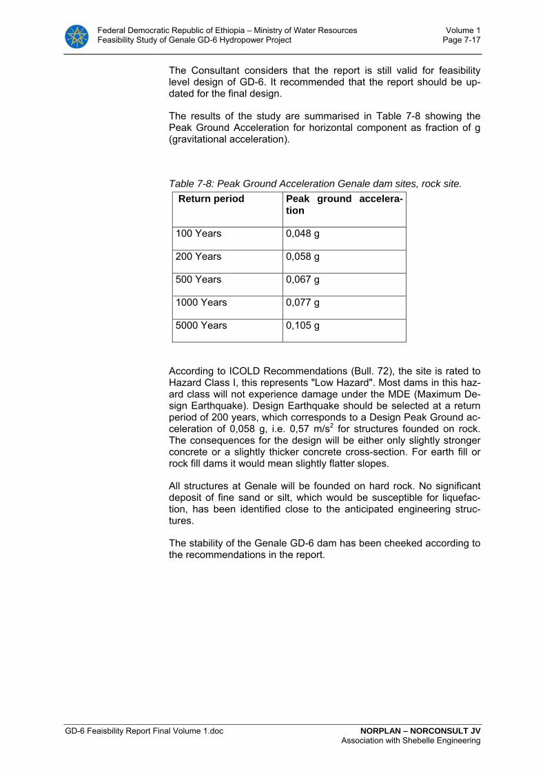
Federal Democratic Republic of Ethiopia – Ministry of Water Resources Volume 1 Feasibility Study of Genale GD-6 Hydropower Project Page 7-17
GD-6 Feaisbility Report Final Volume 1.doc NORPLAN – NORCONSULT JV Association with Shebelle Engineering
The Consultant considers that the report is still valid for feasibility level design of GD-6. It recommended that the report should be up-dated for the final design.
The results of the study are summarised in Table 7-8 showing the Peak Ground Acceleration for horizontal component as fraction of g (gravitational acceleration).
Table 7-8: Peak Ground Acceleration Genale dam sites, rock site. Return period Peak ground accelera-
tion
100 Years 0,048 g
200 Years 0,058 g
500 Years 0,067 g
1000 Years 0,077 g
5000 Years 0,105 g
According to ICOLD Recommendations (Bull. 72), the site is rated to Hazard Class I, this represents "Low Hazard". Most dams in this haz-ard class will not experience damage under the MDE (Maximum De-sign Earthquake). Design Earthquake should be selected at a return period of 200 years, which corresponds to a Design Peak Ground ac-celeration of 0,058 g, i.e. 0,57 m/s2 for structures founded on rock. The consequences for the design will be either only slightly stronger concrete or a slightly thicker concrete cross-section. For earth fill or rock fill dams it would mean slightly flatter slopes.
All structures at Genale will be founded on hard rock. No significant deposit of fine sand or silt, which would be susceptible for liquefac-tion, has been identified close to the anticipated engineering struc-tures.
The stability of the Genale GD-6 dam has been cheeked according to the recommendations in the report.
Federal Democratic Republic of Ethiopia – Ministry of Water Resources Volume 1 Feasibility Study of Genale GD-6 Hydropower Project Page 8-1
GD-6 Feaisbility Report Final Volume 1.doc NORPLAN – NORCONSULT JV in Association with Shebelle Engineering and WWDSE
8 SURVEYING AND MAPPING
8.1 Introduction
For the Genale GD-6 feasibility study, surveying and mapping has taken place at three different levels:
1. Use of existing maps from Ethiopian Mapping Authority (EMA)
2. 1:10,000 scale maps made specifically for the project based on aerial photography
3. Conventional ground surveying for profiling of specific hydropower component sites
In this chapter the various mapping and surveys carried out are de-scribed. There is a supporting document, Annex 3F "Surveying and Mapping", in Volume 3 containing various data, reports and results.
8.2 Maps from Ethiopian Mapping Authority
Maps from EMA at two different scales were used on the project:
• 1:250 000 maps - these cover the whole country and were used for investigation of roads and transmission line alignments.
• 1:50 000 maps - these maps cover most of the country and show contours at 20 m intervals. The 1:50 000 scale map; KEFENEY 0540-C2, prepared by EMA based on aerial photography from 1991, cover the whole layout of the power scheme. Other similar 1:50 000 scale maps have been among the main planning tools for the study/design team while dealing with the Genale GD-6 reservoir catchments areas, access roads, other infrastructure re-lated to the project and transmission line routes.
8.3 Project mapping from aerial photography
For the major planning activities, maps at 1:10,000 scale with 5m contours were produces specifically for the project and covered 297 km2. The ground control, aerial triangulation, and cartographic pro-duction were carried out by Photomap Ltd. of Kenya. The mapping was based on the EMA aerial photographs at approximately 1:56,000 scale taken in November and December 1991.
The photo control and ground survey were carried out using static GPS observations. In addition to the 20 photo control points, six per-manent beacons were established as intervisible pairs as a base for further surveys; two at the proposed dam site, two near the proposed power house and two near the proposed outlet. A survey mark de-scription sheet has been filled out for each of these marks and is con-tained in the Annex 3F.
The raw data measurements were supplied in World Geodetic Sys-tem WGS 84 and then transformed to the local UTM system for Zone 37. The following references were used:

Federal Democratic Republic of Ethiopia – Ministry of Water Resources Volume 1 Feasibility Study of Genale GD-6 Hydropower Project Page 8-2
GD-6 Feaisbility Report Final Volume 1.doc NORPLAN – NORCONSULT JV in Association with Shebelle Engineering and WWDSE
Ellipsoid: Clarke 1880 (modified)
Datum: Adindan (30th Arc)
Map projection: Local UTM, Zone 37
Level datum: Medomena 0540-S3 H=1381.78
The map production took place in Photomap's office in Nairobi. The data capture and photogrammetric compilation was done by Wild, digital plotters which sends the data to the Kork Digital Mapping Sys-tem graphic software. Final editing was done using AutoCAD and ArcView GIS. All features appearing on the maps are presented in separate layers e.g. roads, buildings, contours, rivers, text etc. The topographic features are 3-dimensional and possess X, Y and Z co-ordinate values and are suitable for direct input to the consultant's ter-rain modelling programs. The maps were delivered to the consultant in both paper and digital form as 3-dimensional AutoCAD files.
A survey report and aerial photography film report and map produc-tion report from Photomap is contained in the Volume 3, Annex 3 F, "Surveying and Mapping"
8.4 Ground Surveys
Additional topographic surveys have been carried out covering the proposed dam sites in detail. These surveys have been done using total stations and are based on the control points provided during the photogrammetric control. By adopting this technique the Consultant has ensured that the entire mapping program is based on a common grid and datum. The additional surveys have supplemented the digital terrain model such that accurate contours of 1m can be generated for the surveyed area.
Details of the additional topographic survey at the dam sites are de-scribed in Annex 3 F in Volume 3 of the report.

Federal Democratic Republic of Ethiopia – Ministry of Water Resources Volume 1 Feasibility Study of the GD-6 Hydropower Project Page 9-1
Chapter 10 NORPLAN – NORCONSULT Draft Report in Association with Shebelle Engineering
9 RESERVOIR OPERATION AND POWER PRODUC-TION
Reference is made to Annex 3 A in Volume 3 for the various attach-ments referred to in the text. The attachments contain data and de-tailed simulation results. The results given in Attachment 15-17 are for optimisation purposes, and do not include final selection of turbine equipment, and the capacity and energy output is slightly lower than the final.
9.1 Objectives
The objective of the reservoir operation studies was to evaluate res-ervoir regulation and power plant output for a number of alternative dam heights (full supply levels) and turbine discharges of the GD-6 project.
The configuration of the Genale River hydroelectric schemes is de-fined by the GD-3 storage reservoir and power plant, from which the downstream power plants, GD-5 and GD-6, without appreciable stor-age, is driven by pre-regulated flow from GD-3.
The following chapters of this report present a description of the ap-plied methodology, data preparation and results obtained.
9.2 Methodology
9.2.1 Introduction
The Consultant used the Norwegian software model, nMAG2004 for simulation purposes. An introductory description of the model is at-tached in Annex 3A.
The nMAG 2004 simulation model can be applied to simulate the wa-ter balance and flow routing through a system of inter-connected wa-ter courses or bodies, comprising river reaches, natural lakes, regula-tion reservoirs and hydroelectric plants.
The input matrix includes the following main parameters, to be se-lected by user:
- Reservoir data, volume-area curve, evaporation etc. as de-scribed above
- Turbine discharge (m3/s) - Nominal gross head, (m) - Head loss coefficient (s2/m5) - Control point, if minimum flow releases for downstream re-
quirement - Restriction data, compensation flow etc. - Operational strategy
o Annual average turbine discharge o Daily and yearly demand curves o Daily and yearly energy market prices

Federal Democratic Republic of Ethiopia – Ministry of Water Resources Volume 1 Feasibility Study of the GD-6 Hydropower Project Page 9-2
Chapter 10 NORPLAN – NORCONSULT Draft Report in Association with Shebelle Engineering
9.2.2 GD-3
The upstream located Genale GD-3 power plant is designed to Fea-sibility level by Lahmeyer/Yeshi Ber, 2007. The study concludes with the following key features:
Table 9-1: Summary of project characteristics GD-3
Reservoir
FSL
MOL
Volume
1120 masl
1080 masl
2344 million m3
Average inflow 1) 95.8m3/s
Average turbine outflow 83.9 m3/s
Maximum turbine discharge 116.0 m3/s
Turbine number and type 3 x Francis
Installed capacity 254 MW
Average energy 2) 1640 GWh/year
Firm energy 1600 GWh/year 1)Hydrology series 1984-2004 2)Lahmeyer simulation.
In order to evaluate the combined performance of 2 or 3-component schemes in the Genale River Cascade, the GD-3 has to be included in the simulation model to allow for variation in reservoir releases de-pending on incremental inflows downstream. The simulated regulated inflow to GD-6 is shown in Figure 9-1below.
0
50
100
150
200
250
Jan Feb Mar Apr Mai Jun Jul Aug Sep Okt Nov Des
m3/
s
GD-6 natural inflowGD-6 regulated inflow
Figure 9-1: Natural and regulated monthly inflow to GD-6
Figure 9-1 shows clearly the regulation capacity of the GD-3 reser-voir. The inflow to GD-6 will be well regulated, giving an almost firm inflow to GD-6 simulation model of 84 m3/s.
9.2.3 Reservoir operation
For the present evaluation purpose, the principal aim of the model is to maximise the power and energy generation of GD-3 and GD-6 in

Federal Democratic Republic of Ethiopia – Ministry of Water Resources Volume 1 Feasibility Study of the GD-6 Hydropower Project Page 9-3
Chapter 10 NORPLAN – NORCONSULT Draft Report in Association with Shebelle Engineering
combined operation, considering annual and seasonal hydrological variations contained in the inflow series, reservoir characteristics and operation rules, evaporation losses and downstream water require-ments.
The reservoir operation is simulated for daily time intervals applying:
- Daily inflow data (m3/s), with scaling factor from Chenemasa. - Turbine flow (m3/s) - Evaporation, calculated daily, based on monthly average figure.
The relation between reservoir level, volume and surface area is defined according to the reservoir topography as given in Figure 9-2. The regu-lation of the GD-3 reservoir is set as fixed with:
HRWL 1120 masl, and
LRWL 1080 masl
Reservoir volume 2344 mill m3
The simulation model optimises the energy output for a given reser-voir alternative, by an iterative process. Firm energy is defined on the basis of the continuously generated power, equalled or exceeded for a given percentage of time, 95% (demand coverage of about 98.8% in the model).
The output of the model can be determined by the user, to present results of the simulation comprising tabulations and statistics of the time series of:
1. Inflows for each module, m3/s 2. Outflow for each module, m3/s 3. Spill and bypass, m3/s 4. Reservoir levels and volume, masl and mill m3 5. Power and energy output, MW and GWh 6. Value of energy, mill USD
All results can be individually selected and stored in data files to facili-tate post processing and analysis.
9.2.4 Power plant
Daily values of the power output are calculated for each combination of H/Q with the power formula:
P = 9.81 ηt ηg Q Hn
where:
P generation capacity, MW ηt turbine efficiency (function of Q and H) ηg generator efficiency (constant or variable with output) Q turbine discharge. m3/s Hn net head, m

Federal Democratic Republic of Ethiopia – Ministry of Water Resources Volume 1 Feasibility Study of the GD-6 Hydropower Project Page 9-4
Chapter 10 NORPLAN – NORCONSULT Draft Report in Association with Shebelle Engineering
9.3 Data preparation
9.3.1 Reservoir
The basic reservoir topography is defined by Elevation-Area-Capacity relationships, which for GD-6 were derived from detailed map (5 m contours) of the reservoir area which is described in Chapter 0. GD-3 reservoir curve is taken from the feasibility study.
Figure 9-2: Reservoir curve GD-3 (up) and GD-6 (down)
For the GD-6,reservoir, a number of alternative operating limits for:

Federal Democratic Republic of Ethiopia – Ministry of Water Resources Volume 1 Feasibility Study of the GD-6 Hydropower Project Page 9-5
Chapter 10 NORPLAN – NORCONSULT Draft Report in Association with Shebelle Engineering
- Full supply level (FSL) - Minimum operating level (MOL)
defines the active storages available for the-simulation.
9.3.2 Operating rules
The operation of GD-6 is depending of the water release from GD-3, set to be 83.9 m3/s as annual average, with a maximum turbine dis-charge of 116 m3/s. The incremental yearly average inflow between GD-3 and GD-6 is 6.5 m3/s. The turbine discharge of GD-6 should hence be higher, in the range of 118 to 124 m3/s.
As used for the calculation of firm power at GD-3, a 95% coverage (time exceedence basis) was applied. A 95% reliability level implies the acceptance of 5% failures over time, or up to 13 monthly deficits within the 24-year simulation period. This equals 98.5-98.8% de-mand coverage in the nMAG model.
In the event of a deficit, the reservoir reaches minimum operating level and water release is restricted to inflow in that period. The oc-currence, magnitude and duration of the deficits are, however, unre-stricted in ordinary Firm Energy definition, while in the nMAG the magnitude of the deficit affects the Demand Coverage.
9.3.3 Hydrological inputs
All hydrological inputs were determined in the hydrological investigations reported in Chapter 6, and Volume 3, Annex 3 B.
Inflow series
In the course of the present study the Genale daily flow series were updated up to 2007. This allowed compiling the series of observed flows at Chenemasa for the period from 1973 to 2007. However due to the dubious quality of Chenemasa streamflows for period 1973-1983, as the basis for derivation of inflow series to reservoirs at the GD-3 and GD-6 dam sites, the 1984-2007 series were used. The ac-tual flow characteristics are given in Table 9-2 and monthly flows at the respective project sites are shown in Table 9-3.
Table 9-2: Flow characteristics of Genale River downstream of Chenemasa.
Incremental Basin Chene-masa - GD-3
GD-3 - GD-6
Area (km2) 1255 2911 Mean elevation (m a.s.l) 1430 1280 Mean annual runoff (mm) 89.6 70.5 Mean annual flow (m3/s) 3.6 6.5 Mean annual flow at Chenemasa (m3/s) 92.2 92.2 mean annual flow at site (m3/s) 95.8 102.3
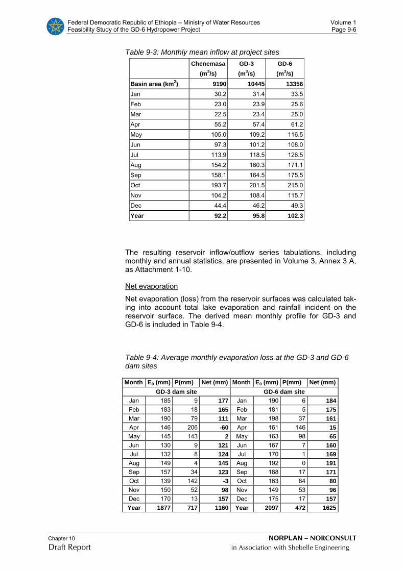
Federal Democratic Republic of Ethiopia – Ministry of Water Resources Volume 1 Feasibility Study of the GD-6 Hydropower Project Page 9-6
Chapter 10 NORPLAN – NORCONSULT Draft Report in Association with Shebelle Engineering
Table 9-3: Monthly mean inflow at project sites
Chenemasa
(m3/s) GD-3 (m3/s)
GD-6 (m3/s)
Basin area (km2) 9190 10445 13356 Jan 30.2 31.4 33.5 Feb 23.0 23.9 25.6 Mar 22.5 23.4 25.0 Apr 55.2 57.4 61.2 May 105.0 109.2 116.5 Jun 97.3 101.2 108.0 Jul 113.9 118.5 126.5 Aug 154.2 160.3 171.1 Sep 158.1 164.5 175.5 Oct 193.7 201.5 215.0 Nov 104.2 108.4 115.7 Dec 44.4 46.2 49.3
Year 92.2 95.8 102.3
The resulting reservoir inflow/outflow series tabulations, including monthly and annual statistics, are presented in Volume 3, Annex 3 A, as Attachment 1-10.
Net evaporation
Net evaporation (loss) from the reservoir surfaces was calculated tak-ing into account total lake evaporation and rainfall incident on the reservoir surface. The derived mean monthly profile for GD-3 and GD-6 is included in Table 9-4.
Table 9-4: Average monthly evaporation loss at the GD-3 and GD-6 dam sites
Month E0 (mm) P(mm) Net (mm) Month E0 (mm) P(mm) Net (mm)GD-3 dam site GD-6 dam site
Jan 185 9 177 Jan 190 6 184 Feb 183 18 165 Feb 181 5 175 Mar 190 79 111 Mar 198 37 161 Apr 146 206 -60 Apr 161 146 15 May 145 143 2 May 163 98 65 Jun 130 9 121 Jun 167 7 160 Jul 132 8 124 Jul 170 1 169 Aug 149 4 145 Aug 192 0 191 Sep 157 34 123 Sep 188 17 171 Oct 139 142 -3 Oct 163 84 80 Nov 150 52 98 Nov 149 53 96 Dec 170 13 157 Dec 175 17 157 Year 1877 717 1160 Year 2097 472 1625

Federal Democratic Republic of Ethiopia – Ministry of Water Resources Volume 1 Feasibility Study of the GD-6 Hydropower Project Page 9-7
Chapter 10 NORPLAN – NORCONSULT Draft Report in Association with Shebelle Engineering
Downstream water demands
The lower Genale Irrigation Scheme will require an average monthly minimum flow as given in the Genale Dawa Master Plan, see Table 9-5. The water requirement is entered in the model as a minimum re-lease from GD-6. .
Table 9-5: Monthly average water requirement for Lower Genale Irri-gation plant
Jan Feb Mar Apr Mai Jun Jul Aug Sep Oct Nov Des
Q m3/s 13.2 7.2 10.6 21.2 22.2 13.8 9.8 15.0 24.7 28.6 26 20.4
9.3.4 Power plant parameters
Efficiencies
A standard efficiency curve for Francis turbine was applied. The head range at GD-6 is limited and will not affect the efficiency. Maximum efficiency at the optimal operation point corresponds to 94 %.
A combined efficiency of the electrical equipment was set to a con-stant value of 97.5 %.
As GD-3 has major change in head, slightly lower efficiency is used for that power plant in the model.
Head loss
The Head loss of the optimised TBM tunnel cross section is calcu-lated to be around 6,0 m. The Head loss shall be entered in the model as a Head loss coefficient in s2/m5 correcting the Head loss according to actual turbine discharge.
Tail water rating
The Tail water level fluctuation is included in the calculations as part of the Head loss coefficient. Calculation of a reliable Tail water level curve has been difficult since surveying of the river profile at the tail-race was not possible during the surveying campaigns.
At the turbine discharge of 120 m3/s, the Tail water level at the outlet reaches 351 masl, increasing to about el. 357 during flood.
Compensation flow
The compensation flow release at GD-6 Dam site is set to 2.5 m3/s throughout the year.
Firm energy output
The firm energy level is selected as an input to the model by the user. The model then simulates the demand coverage based on the se-

Federal Democratic Republic of Ethiopia – Ministry of Water Resources Volume 1 Feasibility Study of the GD-6 Hydropower Project Page 9-8
Chapter 10 NORPLAN – NORCONSULT Draft Report in Association with Shebelle Engineering
lected level of firm energy. The firm energy is then adjusted by the user, until the demand coverage is 98.8% (95% firm energy).
9.4 Reservoir operation simulation
Given the task of evaluating and comparing a number of alternative project configurations in terms of dam height/full supply level, mini-mum operating level and installed capacity in GD-6, in-depth analysis is required through repeated simulation for numerous combinations of these parameters.
9.4.1 Alternative full supply level
Power simulation analysis was carried out systematically for four al-ternative reservoirs full supply levels (FSL) varying between el. 570 – 600 masl. MOL was considered to be 5 – 10 m lower.
Installed capacity variants
The installed capacity of GD-6 fully depends on the outflow from GD-3, 116 m3/s, and the GD-6 turbine discharge was then varied between 116 – 124 m3/s in steps of 2 m3/s.
The turbine discharge varies only from of 1.15 – 1.21 x mean flow.
The result of the simulations is given in detail in a table in Volume 3, Annex 3A, Attachment 15, and a brief summary in Table 9-6, below
Table 9-6: Energy potential of GD-3 GD-6 cascade Turb. disch 118 m3/s 120 m3/s
FSL [masl]
MOL [masl]
Firm en‐ergy
[GWh/y]
Average energy [GWh/y]
Firm energy [GWh/y]
Average energy [GWh/y]
570 565 3040 3176
575 570 3080 3210
580 575 3100 3244 3100 3246
585 580 3140 3279 3140 3281
585 583 3140 3293
590 585 3170 3314 3170 3316
595 590 3200 3348 3200 3350
600 593 3230 3383 3230 3385
9.4.2 Comparing minimum operation level
In order to evaluate firm power and energy generation of the cascade development GD-3 and GD-6, simulations were carried out for differ-ent MOL reservoir levels. The summary in Table 9-7 below refers to turbine discharge 118 m3/s and shows that the MOL could be in-creased from initial estimates.
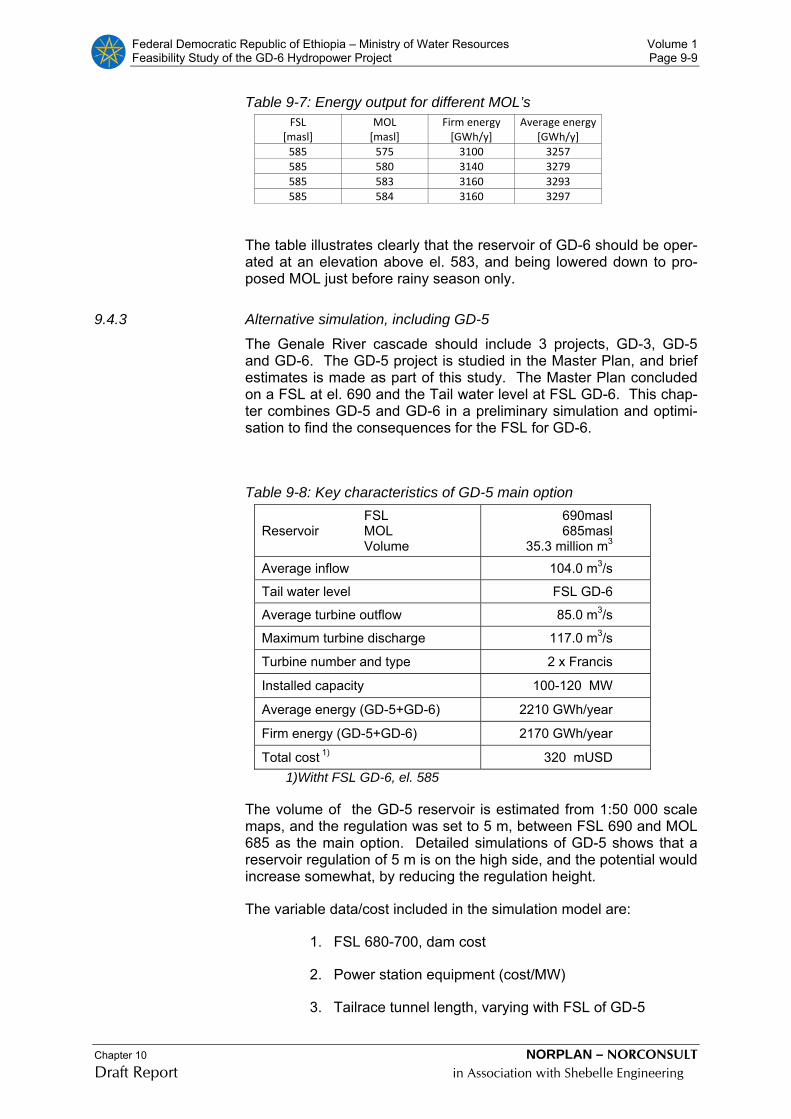
Federal Democratic Republic of Ethiopia – Ministry of Water Resources Volume 1 Feasibility Study of the GD-6 Hydropower Project Page 9-9
Chapter 10 NORPLAN – NORCONSULT Draft Report in Association with Shebelle Engineering
Table 9-7: Energy output for different MOL’s FSL
[masl] MOL [masl]
Firm energy [GWh/y]
Average energy [GWh/y]
585 575 3100 3257 585 580 3140 3279 585 583 3160 3293 585 584 3160 3297
The table illustrates clearly that the reservoir of GD-6 should be oper-ated at an elevation above el. 583, and being lowered down to pro-posed MOL just before rainy season only.
9.4.3 Alternative simulation, including GD-5
The Genale River cascade should include 3 projects, GD-3, GD-5 and GD-6. The GD-5 project is studied in the Master Plan, and brief estimates is made as part of this study. The Master Plan concluded on a FSL at el. 690 and the Tail water level at FSL GD-6. This chap-ter combines GD-5 and GD-6 in a preliminary simulation and optimi-sation to find the consequences for the FSL for GD-6.
Table 9-8: Key characteristics of GD-5 main option
Reservoir FSL MOL Volume
690masl 685masl
35.3 million m3
Average inflow 104.0 m3/s
Tail water level FSL GD-6
Average turbine outflow 85.0 m3/s
Maximum turbine discharge 117.0 m3/s
Turbine number and type 2 x Francis
Installed capacity 100-120 MW
Average energy (GD-5+GD-6) 2210 GWh/year
Firm energy (GD-5+GD-6) 2170 GWh/year
Total cost 1) 320 mUSD 1)Witht FSL GD-6, el. 585
The volume of the GD-5 reservoir is estimated from 1:50 000 scale maps, and the regulation was set to 5 m, between FSL 690 and MOL 685 as the main option. Detailed simulations of GD-5 shows that a reservoir regulation of 5 m is on the high side, and the potential would increase somewhat, by reducing the regulation height.
The variable data/cost included in the simulation model are:
1. FSL 680-700, dam cost
2. Power station equipment (cost/MW)
3. Tailrace tunnel length, varying with FSL of GD-5

Federal Democratic Republic of Ethiopia – Ministry of Water Resources Volume 1 Feasibility Study of the GD-6 Hydropower Project Page 9-10
Chapter 10 NORPLAN – NORCONSULT Draft Report in Association with Shebelle Engineering
The detailed result of the simulations is presented in Volume 3, An-nex 3A, Attachment 16, with a brief summary of the energy output in Table 9-9 for turbine discharge 118 m3/s. An example of the nMAG result is enclosed in Annex 3A, Attachment 18.
Table 9-9: Energy potential of cascade GD-5 and GD-6 FSL GD‐5 (masl)
MOL GD‐5 [masl]
TWL GD‐5 FSL‐GD6
MOL GD‐6 (masl)
Firm energy (GWh/y]
Average energy [GWh/y]
680 665 570 565 2110 2143
680 675 580 575 2110 2145
680 675 590 585 2110 2147
690 685 570 565 2170 2209
690 685 580 575 2170 2211
690 685 590 585 2170 2212
700 695 570 565 2230 2275
700 695 580 575 2230 2276
700 695 590 585 2230 2278
1) The simulation was made with demand coverage of 98.5%, and the total Firm energy of the cascade referred in the tables, is on the high side.
The average energy from GD-5 is about 600 GWh/year with GD-6 FSL 585.
9.5 Result of optimisation
9.5.1 GD-3 and GD-6
The result of the optimisation of the cascade GD-3 and GD-6 is sum-marised in Table 9-10 and Table 9-11 based on an energy value of 6 and 10 USc/kWh respectively.
In the Consultants opinion 6 USc/kWh is on the low side for optimisa-tion of projects with a lifetime of more than 50 years. Considering hy-dropower projects that should replace thermal plants, some fired with diesel, an energy value of 8-10 USc/kWh is expected to be more relevant in the near future.
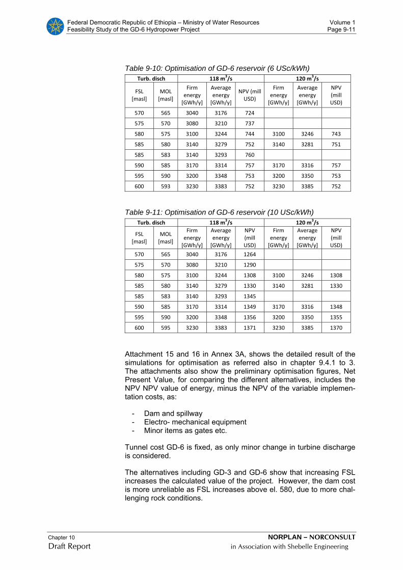
Federal Democratic Republic of Ethiopia – Ministry of Water Resources Volume 1 Feasibility Study of the GD-6 Hydropower Project Page 9-11
Chapter 10 NORPLAN – NORCONSULT Draft Report in Association with Shebelle Engineering
Table 9-10: Optimisation of GD-6 reservoir (6 USc/kWh) Turb. disch 118 m3/s 120 m3/s
FSL [masl]
MOL [masl]
Firm energy [GWh/y]
Average energy [GWh/y]
NPV (mill USD)
Firm energy [GWh/y]
Average energy [GWh/y]
NPV (mill USD)
570 565 3040 3176 724
575 570 3080 3210 737
580 575 3100 3244 744 3100 3246 743
585 580 3140 3279 752 3140 3281 751
585 583 3140 3293 760
590 585 3170 3314 757 3170 3316 757
595 590 3200 3348 753 3200 3350 753
600 593 3230 3383 752 3230 3385 752
Table 9-11: Optimisation of GD-6 reservoir (10 USc/kWh) Turb. disch 118 m3/s 120 m3/s
FSL [masl]
MOL [masl]
Firm energy [GWh/y]
Average energy [GWh/y]
NPV (mill USD)
Firm energy [GWh/y]
Average energy [GWh/y]
NPV (mill USD)
570 565 3040 3176 1264
575 570 3080 3210 1290
580 575 3100 3244 1308 3100 3246 1308
585 580 3140 3279 1330 3140 3281 1330
585 583 3140 3293 1345
590 585 3170 3314 1349 3170 3316 1348
595 590 3200 3348 1356 3200 3350 1355
600 595 3230 3383 1371 3230 3385 1370
Attachment 15 and 16 in Annex 3A, shows the detailed result of the simulations for optimisation as referred also in chapter 9.4.1 to 3. The attachments also show the preliminary optimisation figures, Net Present Value, for comparing the different alternatives, includes the NPV NPV value of energy, minus the NPV of the variable implemen-tation costs, as:
- Dam and spillway - Electro- mechanical equipment - Minor items as gates etc.
Tunnel cost GD-6 is fixed, as only minor change in turbine discharge is considered.
The alternatives including GD-3 and GD-6 show that increasing FSL increases the calculated value of the project. However, the dam cost is more unreliable as FSL increases above el. 580, due to more chal-lenging rock conditions.

Federal Democratic Republic of Ethiopia – Ministry of Water Resources Volume 1 Feasibility Study of the GD-6 Hydropower Project Page 9-12
Chapter 10 NORPLAN – NORCONSULT Draft Report in Association with Shebelle Engineering
9.5.2 GD-3, GD-5 and GD-6
The results of the optimisation of the cascade GD-3, GD-5 and GD-6 is summarised in Table 9-12.
Table 9-12: Optimisation of cascade GD-5 and GD-6
1) The simulation was made with demand coverage of 98.5%, and the total Firm energy of the cascade referred in the tables, is on the high side.
The figures show that the highest NPV relates to a GD-5 FSL of 700 combined with GD-6 FSL at el. 570.
9.6 Conclusions
Based on the simulations results of the GD-3 and GD-6 alternative, the FSL of GD-6 should be at minimum el. 585, while including the GD-5 project in the optimisation it could be lowered down to around el. 570.
The Consultant recommends that the cascade development GD-5 and GD-6 should be further studied before a decision to construct GD-6 is taken. The following preliminary conclusion can be drawn for the design of GD-6:
1. Without GD-5
a. FSL 585 masl
b. Turbine discharge 120 m3/s
2. With GD-5
a. FSL GD-6, el. 570
b. FSL GD-5, to be further investigated
If there is doubt about the feasibility of GD-5, the alternative 1 should be selected. The FSL of 585, still allows for a future implementation
FSL GD‐5 (masl)
MOL GD‐5 [masl]
TWL GD‐5 FSL‐GD6
MOL GD‐6 (masl)
Firm energy (GWh/y] 1)
Average energy [GWh/y]
NPV (mill USD)
680 665 570 565 2110 2143 1904
680 675 580 575 2110 2145 1896
680 675 590 585 2110 2147 1881
690 685 570 565 2170 2209 1949
690 685 580 575 2170 2211 1941
690 685 590 585 2170 2212 1926
700 695 570 565 2230 2275 1990
700 695 580 575 2230 2276 1981
700 695 590 585 2230 2278 1966
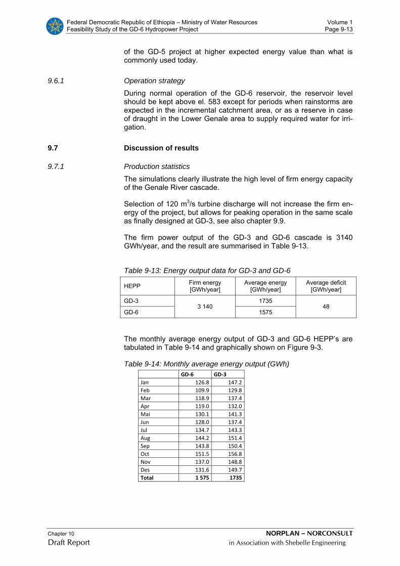
Federal Democratic Republic of Ethiopia – Ministry of Water Resources Volume 1 Feasibility Study of the GD-6 Hydropower Project Page 9-13
Chapter 10 NORPLAN – NORCONSULT Draft Report in Association with Shebelle Engineering
of the GD-5 project at higher expected energy value than what is commonly used today.
9.6.1 Operation strategy
During normal operation of the GD-6 reservoir, the reservoir level should be kept above el. 583 except for periods when rainstorms are expected in the incremental catchment area, or as a reserve in case of draught in the Lower Genale area to supply required water for irri-gation.
9.7 Discussion of results
9.7.1 Production statistics
The simulations clearly illustrate the high level of firm energy capacity of the Genale River cascade.
Selection of 120 m3/s turbine discharge will not increase the firm en-ergy of the project, but allows for peaking operation in the same scale as finally designed at GD-3, see also chapter 9.9.
The firm power output of the GD-3 and GD-6 cascade is 3140 GWh/year, and the result are summarised in Table 9-13.
Table 9-13: Energy output data for GD-3 and GD-6
HEPP Firm energy [GWh/year]
Average energy [GWh/year]
Average deficit [GWh/year]
GD-3 3 140
1735 48
GD-6 1575
The monthly average energy output of GD-3 and GD-6 HEPP’s are tabulated in Table 9-14 and graphically shown on Figure 9-3.
Table 9-14: Monthly average energy output (GWh) GD‐6 GD‐3
Jan 126.8 147.2Feb 109.9 129.8Mar 118.9 137.4Apr 119.0 132.0Mai 130.1 141.3Jun 128.0 137.4Jul 134.7 143.3Aug 144.2 151.4Sep 143.8 150.4Oct 151.5 156.8Nov 137.0 148.8Des 131.6 149.7Total 1 575 1735
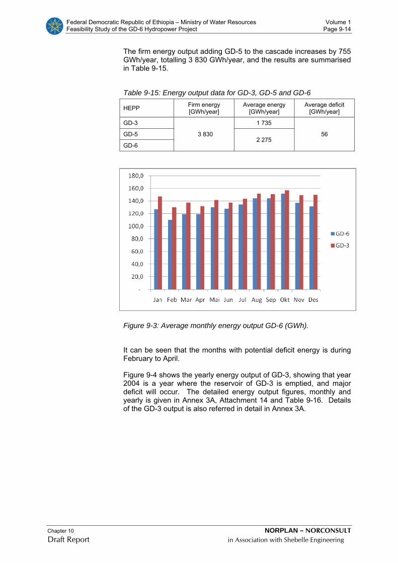
Federal Democratic Republic of Ethiopia – Ministry of Water Resources Volume 1 Feasibility Study of the GD-6 Hydropower Project Page 9-14
Chapter 10 NORPLAN – NORCONSULT Draft Report in Association with Shebelle Engineering
The firm energy output adding GD-5 to the cascade increases by 755 GWh/year, totalling 3 830 GWh/year, and the results are summarised in Table 9-15.
Table 9-15: Energy output data for GD-3, GD-5 and GD-6
HEPP Firm energy [GWh/year]
Average energy [GWh/year]
Average deficit [GWh/year]
GD-3
3 830
1 735
56 GD-5 2 275
GD-6
Figure 9-3: Average monthly energy output GD-6 (GWh).
It can be seen that the months with potential deficit energy is during February to April.
Figure 9-4 shows the yearly energy output of GD-3, showing that year 2004 is a year where the reservoir of GD-3 is emptied, and major deficit will occur. The detailed energy output figures, monthly and yearly is given in Annex 3A, Attachment 14 and Table 9-16. Details of the GD-3 output is also referred in detail in Annex 3A.
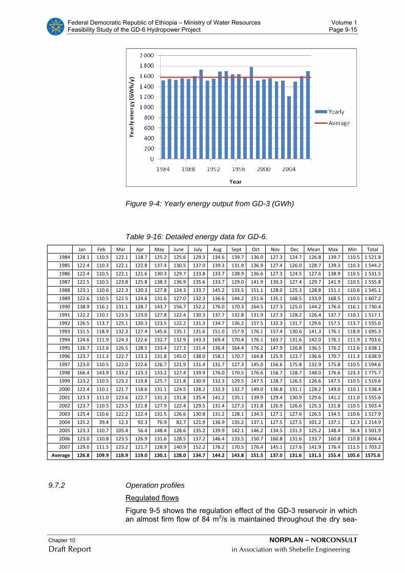
Federal Democratic Republic of Ethiopia – Ministry of Water Resources Volume 1 Feasibility Study of the GD-6 Hydropower Project Page 9-15
Chapter 10 NORPLAN – NORCONSULT Draft Report in Association with Shebelle Engineering
Figure 9-4: Yearly energy output from GD-3 (GWh)
Table 9-16: Detailed energy data for GD-6. Jan Feb Mar Apr May June July Aug Sept Oct Nov Dec Mean Max Min Total
1984 128.1 110.5 122.1 118.7 125.2 125.6 129.3 134.6 139.7 136.0 127.3 124.7 126.8 139.7 110.5 1 521.8
1985 122.4 110.3 122.1 122.8 137.4 130.5 137.0 139.3 131.9 136.9 127.4 126.0 128.7 139.3 110.3 1 544.2
1986 122.4 110.5 122.1 121.6 130.3 129.7 133.8 133.7 138.9 136.6 127.3 124.5 127.6 138.9 110.5 1 531.5
1987 122.5 110.5 123.8 125.8 138.3 136.9 135.6 133.7 129.0 141.9 130.3 127.4 129.7 141.9 110.5 1 555.8
1988 123.1 110.6 122.3 120.3 127.8 124.3 133.7 145.2 133.5 151.1 128.0 125.3 128.8 151.1 110.6 1 545.1
1989 122.6 110.5 122.5 124.6 131.6 127.0 132.3 136.6 144.2 151.6 135.1 168.5 133.9 168.5 110.5 1 607.2
1990 138.9 116.1 131.1 128.7 143.7 156.7 152.2 176.0 170.3 164.5 127.3 125.0 144.2 176.0 116.1 1 730.4
1991 122.2 110.1 123.5 123.0 127.8 122.4 130.3 137.7 132.8 131.9 127.3 128.2 126.4 137.7 110.1 1 517.1
1992 126.5 113.7 125.1 120.3 123.5 122.2 131.3 134.7 136.2 157.5 132.3 131.7 129.6 157.5 113.7 1 555.0
1993 131.5 118.9 132.3 127.4 145.6 135.1 131.6 151.0 157.9 176.1 157.4 130.6 141.3 176.1 118.9 1 695.3
1994 124.6 111.9 124.3 122.6 132.7 132.9 143.3 169.4 170.4 176.1 163.7 131.6 142.0 176.1 111.9 1 703.6
1995 126.7 112.6 126.5 128.5 133.4 127.3 131.4 136.4 164.4 176.2 147.9 126.8 136.5 176.2 112.6 1 638.1
1996 123.7 111.3 122.7 123.3 131.8 145.0 138.0 158.1 170.7 164.8 125.9 123.7 136.6 170.7 111.3 1 638.9
1997 123.0 110.5 122.0 122.6 126.7 121.9 131.4 131.7 127.3 145.0 156.6 175.8 132.9 175.8 110.5 1 594.6
1998 166.4 143.9 133.2 123.3 133.2 127.4 139.9 176.0 170.5 176.6 156.7 128.7 148.0 176.6 123.3 1 775.7
1999 123.2 110.5 123.2 119.8 125.7 121.8 130.9 132.3 129.5 147.5 128.7 126.5 126.6 147.5 110.5 1 519.6
2000 122.4 110.1 121.7 118.6 131.1 124.5 128.2 132.3 132.7 149.0 136.8 131.1 128.2 149.0 110.1 1 538.4
2001 123.3 111.0 123.6 122.7 131.3 131.8 135.4 141.2 135.1 139.9 129.4 130.9 129.6 141.2 111.0 1 555.6
2002 123.7 110.5 123.5 121.8 127.9 122.4 129.5 131.4 127.3 131.8 126.9 126.6 125.3 131.8 110.5 1 503.4
2003 125.4 110.6 122.2 122.4 131.5 126.6 130.8 131.2 128.1 134.5 127.1 127.6 126.5 134.5 110.6 1 517.9
2004 125.2 39.4 12.3 92.3 76.9 82.7 121.9 136.9 135.2 137.1 127.5 127.5 101.2 137.1 12.3 1 214.9
2005 123.3 110.7 105.4 56.4 148.4 128.6 135.2 139.9 142.1 146.2 134.5 131.3 125.2 148.4 56.4 1 501.9
2006 123.0 110.8 123.5 126.9 131.6 128.5 137.2 146.4 133.5 150.7 160.8 131.6 133.7 160.8 110.8 1 604.4
2007 129.0 111.5 123.2 121.7 128.9 140.9 152.2 176.2 170.5 176.4 145.1 127.6 141.9 176.4 111.5 1 703.2
Average 126.8 109.9 118.9 119.0 130.1 128.0 134.7 144.2 143.8 151.5 137.0 131.6 131.3 155.4 105.6 1575.6
9.7.2 Operation profiles
Regulated flows
Figure 9-5 shows the regulation effect of the GD-3 reservoir in which an almost firm flow of 84 m3/s is maintained throughout the dry sea-

Federal Democratic Republic of Ethiopia – Ministry of Water Resources Volume 1 Feasibility Study of the GD-6 Hydropower Project Page 9-16
Chapter 10 NORPLAN – NORCONSULT Draft Report in Association with Shebelle Engineering
son. This represents an augmentation of more than 60 m3/s above average low-flow rates which occur between February and March.
In the normal high-flow season between August and October, aver-age flow rates are reduced by about 40%.
The flow duration curve before and after GD-3 reservoir is shown in Figure 9-6.
0
50
100
150
200
250
Jan Feb Mar Apr Mai Jun Jul Aug Sep Okt Nov Des
m3/
s
GD-6 natural inflowGD-6 regulated inflow
Figure 9-5: GD-6 monthly flow characteristics with and without GD-3 reservoir.
0
100
200
300
400
500
600
0.0 % 20.0 % 40.0 % 60.0 % 80.0 % 100.0 %Duration
Flow
(m3/
s)
Total GD6
Regulated f low GD 6
Figure 9-6: Flow duration curve before and after GD-3
Reservoir operation

Federal Democratic Republic of Ethiopia – Ministry of Water Resources Volume 1 Feasibility Study of the GD-6 Hydropower Project Page 9-17
Chapter 10 NORPLAN – NORCONSULT Draft Report in Association with Shebelle Engineering
The following reservoir curves are shown in the next pages
- Figure 9-7: Reservoir level GD-3 Figure 9-8: Reservoir volume GD-3
- Figure 9-9: Reservoir level duration curve, GD-3. - Figure 9-10: Monthly mean, max and mIn reservoir level - Figure 9-11: Change in reservoir volume by year - Figure 9-12: Reservoir level GD-6
Reservoir level GD3
1080
1085
1090
1095
1100
1105
1110
1115
1120
1125
1984 1986 1988 1990 1992 1994 1996 1998 2000 2002 2004 2006
Figure 9-7: Reservoir level GD-3
Reservoir volume GD 3
0
500
1000
1500
2000
2500
3000
1984 1986 1988 1990 1992 1994 1996 1998 2000 2002 2004 2006
Figure 9-8: Reservoir volume GD-3
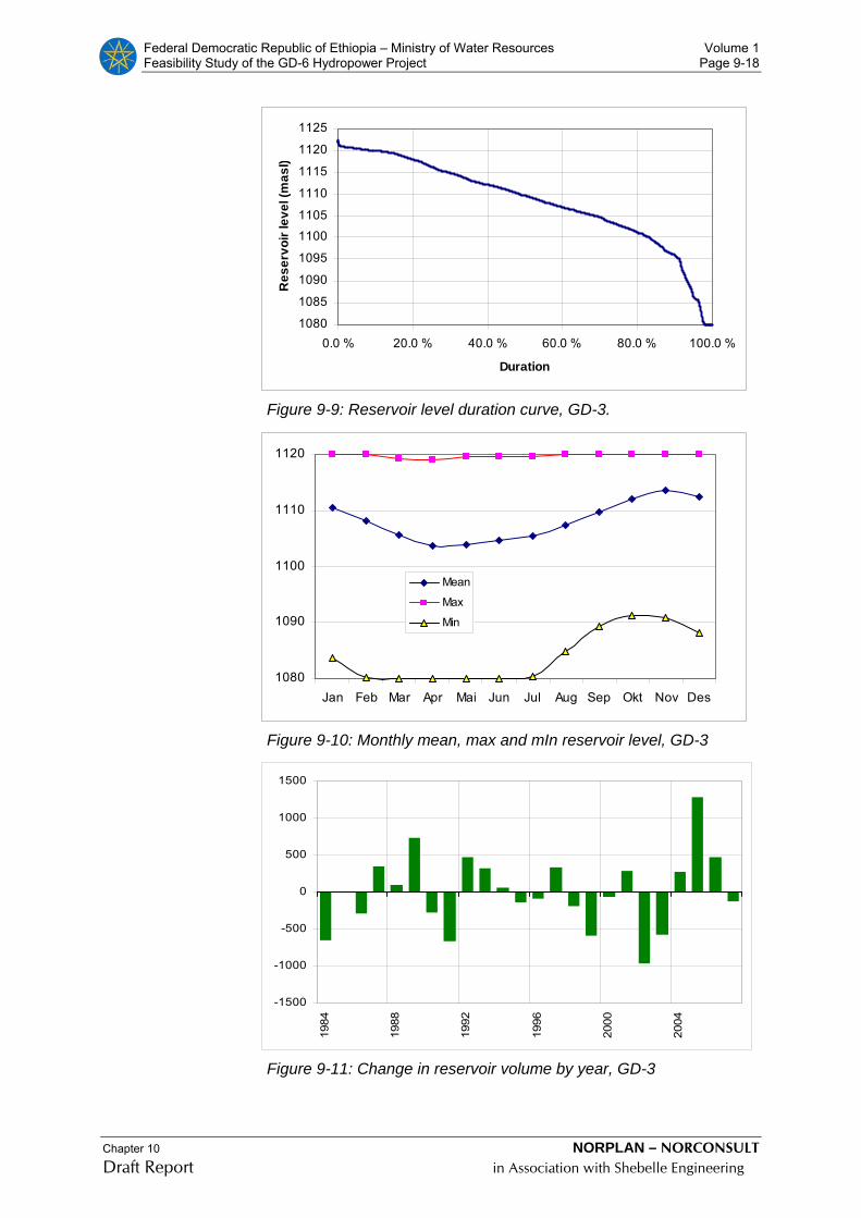
Federal Democratic Republic of Ethiopia – Ministry of Water Resources Volume 1 Feasibility Study of the GD-6 Hydropower Project Page 9-18
Chapter 10 NORPLAN – NORCONSULT Draft Report in Association with Shebelle Engineering
1080
1085
1090
1095
1100
1105
1110
1115
1120
1125
0.0 % 20.0 % 40.0 % 60.0 % 80.0 % 100.0 %
Duration
Res
ervo
ir le
vel (
mas
l)
Figure 9-9: Reservoir level duration curve, GD-3.
1080
1090
1100
1110
1120
Jan Feb Mar Apr Mai Jun Jul Aug Sep Okt Nov Des
Mean
Max
Min
Figure 9-10: Monthly mean, max and mIn reservoir level, GD-3
-1500
-1000
-500
0
500
1000
1500
1984
1988
1992
1996
2000
2004
Figure 9-11: Change in reservoir volume by year, GD-3

Federal Democratic Republic of Ethiopia – Ministry of Water Resources Volume 1 Feasibility Study of the GD-6 Hydropower Project Page 9-19
Chapter 10 NORPLAN – NORCONSULT Draft Report in Association with Shebelle Engineering
Reservoir level GD6
578
580
582
584
586
588
590
592
1984 1986 1988 1990 1992 1994 1996 1998 2000 2002 2004 2006
Figure 9-12: Reservoir level GD-6 (peak floodwater levels is incor-rect)
The GD-3 reservoir curves, , shows the annual cycle of water level variation defined by a gradual drawdown-period between November and April filling in the high flow season from August to November. The GD-6 reservoir, Figure 9-12, reaches, full reservoir conditions in most years.
Only under the most critical conditions, as experienced in 2004 and 2005, the reservoirs are drawn down to minimum operating level dur-ing February and March. 2005 is a wet year, see GD-3 reservoir curve Figure 9-8.
As indicated in the GD-3 reservoir level duration curve , Figure 9-9, for the whole period of generation, near full reservoir conditions are attained for about 10 % of time and less than 10 % of the time the reservoir is below 30% volume. For maximum power generation, res-ervoir levels should be kept as high as possible in order to utilise the best combination of flow, head and turbine efficiency.
Annual time series
The annual series plot of energy output, GD-6, illustrates the Genale River cascades ability of producing firm power. It is only the year 2004 that there is a deficit on yearly basis.

Federal Democratic Republic of Ethiopia – Ministry of Water Resources Volume 1 Feasibility Study of the GD-6 Hydropower Project Page 9-20
Chapter 10 NORPLAN – NORCONSULT Draft Report in Association with Shebelle Engineering
Figure 9-13: Annual time series of generated energy
9.8 Small Hydropower Plant
An environmental water release of 2.5 m3/s is planned at the Dam site.
The Consultant suggests to install a small hydropower unit to gener-ate power from the compensation water release The turbine will be a standard compact Francis unit with horizontal shaft, with a load con-troller to ensure correct water release at all times.
Compensation flow will be released 365 days/year and the turbine will supply firm energy to the 33 kV grid connected to Negele substation.
The average capacity of the unit will be 1.35 MW and the yearly en-ergy output 11.8 GWh.
9.9 Daily operation profiles
The Genale River projects are designed as base load projects, with a plant factor of about 0.73. The annual average turbine output for GD-6 is 180 MW, with a firm capacity of 165 MW. Based on a typical ICS daily load curve, as presented for a weekday in 2007 in Figure 9-14, the GD-6 project could supply a peak output of 250 MW, and cover its relative part of load during the rest of the day.

Federal Democratic Republic of Ethiopia – Ministry of Water Resources Volume 1 Feasibility Study of the GD-6 Hydropower Project Page 9-21
Chapter 10 NORPLAN – NORCONSULT Draft Report in Association with Shebelle Engineering
Figure 9-14: Typical daily load curve

Federal Democratic Republic of Ethiopia – Ministry of Water Resources EIA Report - Vol. 1 Feasibility Study of the GD-6 Hydropower Project Page 10-1
Chapter 10 NORPLAN – NORCONSULT Draft Report in Association with Shebelle Engineering
10 THE EIA STUDY
10.1 Introduction - Extent of the EIA
The construction and operation of a dam and hydropower scheme on the Genale River will result in impacts in both the upstream and the downstream. Some of these impacts will be significant from an eco-logical or socio-economic perspective, and some will not be. The de-limitation of impact zones encompassing the project area and the study area is explained following.
10.1.1 Direct Impact Zone (DIZ)
Inundation of the valley behind the dams and the associated works would create a direct impact zone with the following elements:
• a core area always under water;
• the drawdown zone, around the permanently flooded area;
• A short altered river section between dam and tailrace outlet;
• the shore and periphery of the reservoir; and
• sites of ancillary works, access roads and transmission lines.
10.1.2 Secondary Impact Zone
Secondary Impact Zone (SIZ) encompasses the areas adjacent to the DIZ/reservoir, along access routes and power transmission corridor, which will be effected by the project and people immediately down-stream of the development. This zone includes communities which, although not physically displaced, come into direct contact with the development activities and staff. These communities may rely on re-sources within the DIZ.
10.1.3 Tertiary Impact Zone
Tertiary Impact Zone (TIZ), which encompasses possible issues up-stream and downstream due to the changes in river flow regime and dam wall barrier effects.
Given the extensive study area significant use of satellite imagery and GIS was made in the EIA, to both describe existing baseline condi-tions and to analyse potential change.
The Figure following shows the project location and indicative impact zones. The red box denotes the terrestrial tertiary impact zone, the blue the secondary and the black the direct impact zone.
.
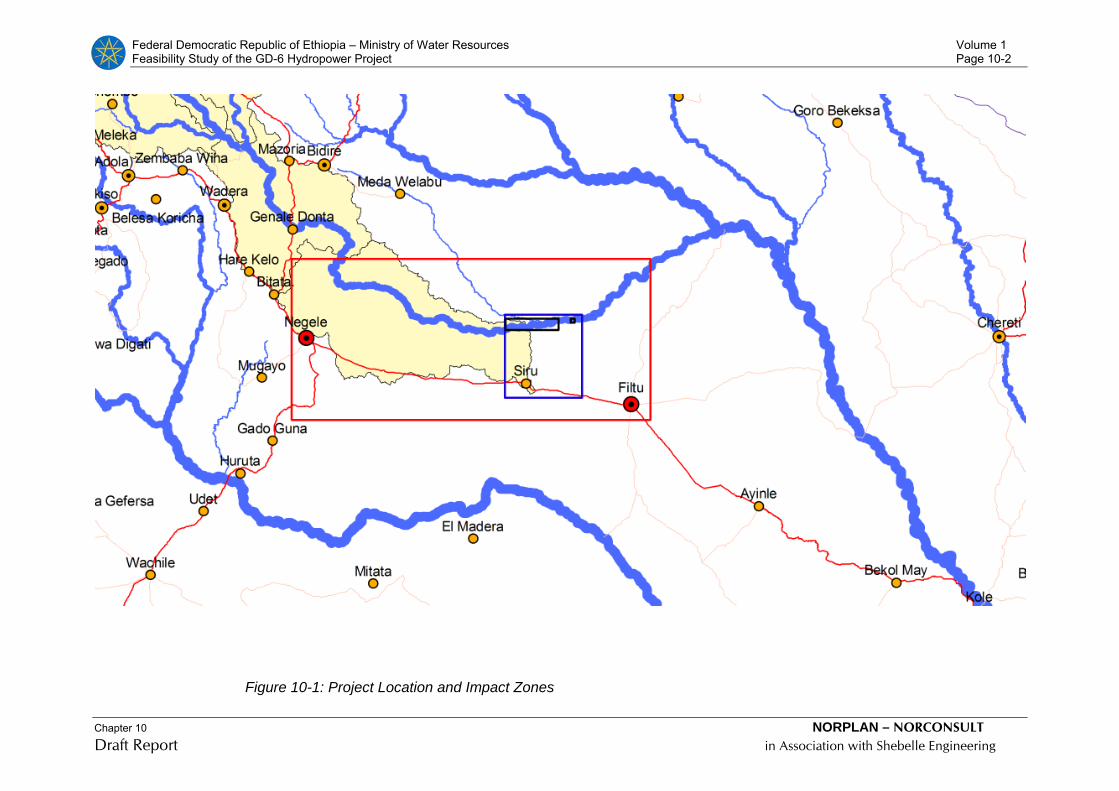
Federal Democratic Republic of Ethiopia – Ministry of Water Resources Volume 1 Feasibility Study of the GD-6 Hydropower Project Page 10-2
Chapter 10 NORPLAN – NORCONSULT Draft Report in Association with Shebelle Engineering
Figure 10-1: Project Location and Impact Zones
Federal Democratic Republic of Ethiopia – Ministry of Water Resources Volume 1 Feasibility Study of the GD-6 Hydropower Project Page 10-3
Chapter 10 NORPLAN – NORCONSULT Draft Report in Association with Shebelle Engineering
10.2 Project Context and Focus
From the perspective of the EIA, critical issues are the landtake for the dam, reservoir and access routes and the changes to the down-stream river flow regime that will occur in the reservoir filling and op-erational phase.
The project area straddles the Somali and Oromia Regions with the Oromia Zone of Bale (Meda Welabu Werede) on the left bank and the Somali Zone of Liben (Liben Werede) on the right bank. Upstream much of the Genale catchment between GD-3 and GD-6 falls within the Oromia Zone of Bore (Liben Werede). The two Zone Capitals are Negele in Bore Zone and Filtu in the Liben Zone. Road access to site will start at Siru which is located on the main road between Negele and Filtu.
The Genale River falls into the Somali-Masai biome and is influenced by both the Somali-Masai and Afro Tropical Highland Biomes. In a regional context, the vegetation of the study area falls under White’s (1983) Somalia-Masai regional centre of endemism. The length and severity of drought and its effect on the natural vegetation and pas-toral populations is different in various parts of this vegetation type. Acacia – Commiphora deciduous bushland is dominant.
The main road between Negele and Filtu is largely settled and wildlife populations are minimal. The river, though, is largely unaffected by development and hosts substantial animal diversity. The project area does not fall into any of the formal protected zones in Ethiopia nor is there informal protection although there is an understanding at the Kebele level that communities are responsible for conservation of wildlife.
The GD-6 Genale River basin is approximately 2,920 km2. The land use varies considerably form intense arable agriculture to open live-stock production systems An assessment of the present land use in the basin indicates that approximately 62.5% of the basin is used for open livestock production a further 19.7% has a mixture of arable and livestock with emphasis on livestock and 17.8 is intense arable agri-culture. Due to the low and erratic rainfall the primary form of farming is pastoralism (cattle, sheep, goats, camels) with smaller areas of ar-able agriculture. The most common crops are; maize, wheat, lowland teff, haricot-beans and sorghum.
There are two kebeles (of the Liben Werede) that are affected by the project (by flooding of the reservoir and reduced flows in the section between the dam wall and the tailrce outlet), these are:
1. Siru (upstream of the dam wall), and
2. Haydimtu (mainly in the area below the dam wall)
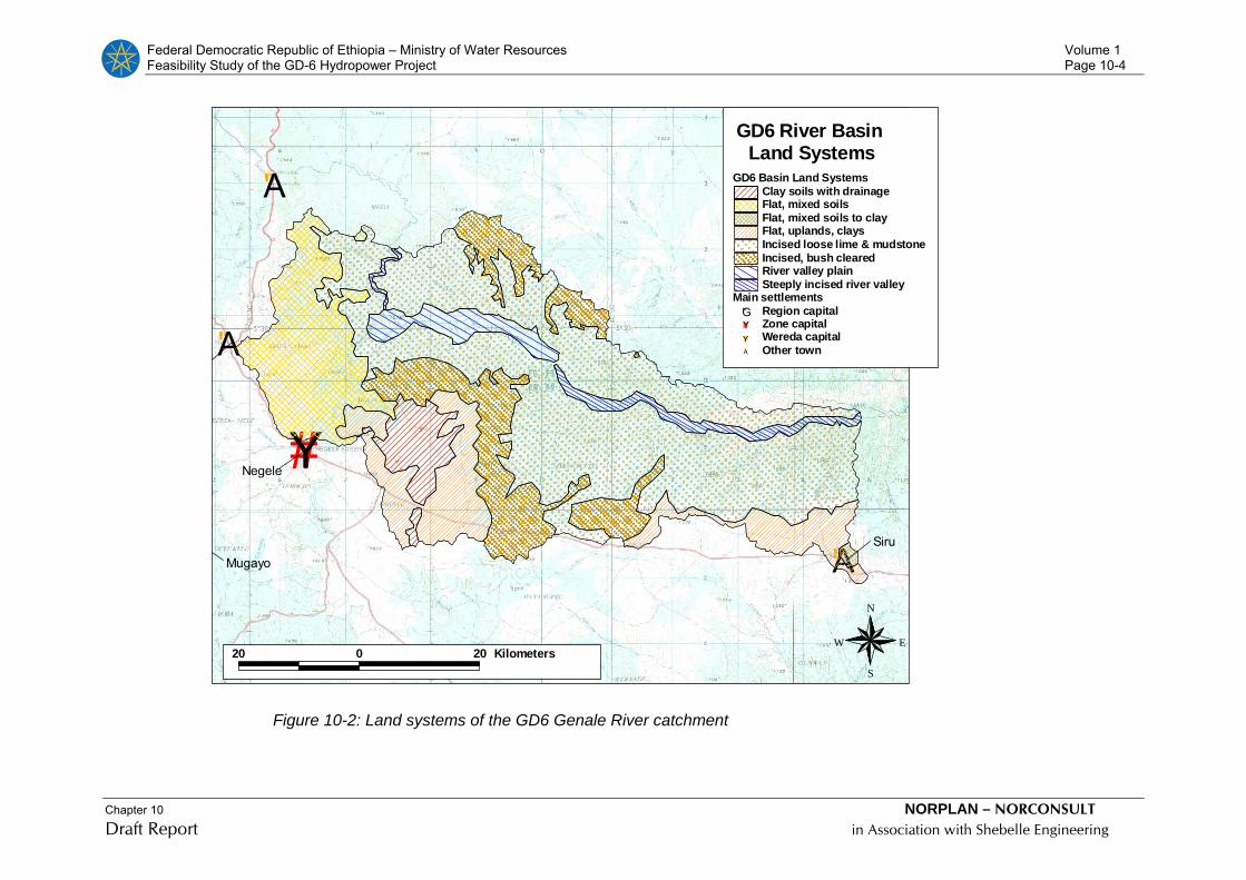
Federal Democratic Republic of Ethiopia – Ministry of Water Resources Volume 1 Feasibility Study of the GD-6 Hydropower Project Page 10-4
Chapter 10 NORPLAN – NORCONSULT Draft Report in Association with Shebelle Engineering
#Y
"A
"A
"AMugayo
#
#
Negele
#
Siru
20 0 20 Kilometers
Main settlements"G Region capital#Y Zone capital#Y Wereda capital"A Other town
GD6 Basin Land SystemsClay soils with drainageFlat, mixed soilsFlat, mixed soils to clayFlat, uplands, claysIncised loose lime & mudstoneIncised, bush clearedRiver valley plainSteeply incised river valley
GD6 River Basin Land Systems
N
EW
S
Figure 10-2: Land systems of the GD6 Genale River catchment
Federal Democratic Republic of Ethiopia – Ministry of Water Resources Volume 1 Feasibility Study of the GD-6 Hydropower Project Page 10-5
Chapter 10 NORPLAN – NORCONSULT Draft Report in Association with Shebelle Engineering
In general land use activities of the project area along the Genale River relate to response to drought conditions in which grazing and water resources in the Dawa river area are depleted. Both kebeles focus their arable agriculture and pastoralism around the Dawa River to the south.
10.2.1 Somali Liben Zone Socio-economic Characteristics
The main socio-economic linkages relevant to the GD-6 project are with the Somali National Regional State (SNRS) and its administra-tive units on the right bank (taken as looking downstream) of the Genale River, focussing on the reservoir area. On the left bank in Oromia there is an absence of settlement in and around the project area and land use appears to be limited and as an extension of activi-ties originating from the right bank.
Somalis are mainly pastoralists and agro-pastoralists. The nomadic or transhumance way of life of pastoralists responds to highly unstable natural environment and to a future-oriented perception of time and space. However, although with arid and semi-arid rangelands pastor-alism may be thought of as the only sustainable economic system in the Somali region, pastoral households are recently becoming more and more attached to semi-permanent settlements in the vicinity of watering points. This may be due to different factors, such as inten-sive water development, constraints to mobility, commercialization and migration of labour.
Digodi is the domination clan in the area and is strongly linked by lineage to the clans of Hawiya, the Hawazle of Hiran, and the Ra-hawein of Baay, Minor ethnic groups such as the Gerri from Hudet and Moyale, and the Maherran from Chisimaio populate the surround-ings of Filtu. Clan uniformity and homogeneity are evident signs of a rigid and impermeable social structure, with strict forms of allegiance and intra/inter-group solidarity. In times of crisis, wealth redistribution, sharing of food resources, and assets concession are all coping mechanisms involving relatives and neighbours.
Patriarchal rules govern social and gender relations, according to a hierarchical power structure. Among the Digodi, land is usually ad-ministered by the elders of the village, who formulate rules about re-source use and distribution according to the Koranic law. Enclosure is however expanding, and many farmers cultivate their own land, fam-ily-inherited plot of land irrespective of the possessions of their clan.
Generally speaking, land tenure rules and access to and control over resources vary from clan to clan, but land is usually a possession of the head of the household, commonly a man. Social and gender divi-sion of labour is also defined in relation to the economic needs of the family and its practices, whether pastoralist or agro-pastoralist.
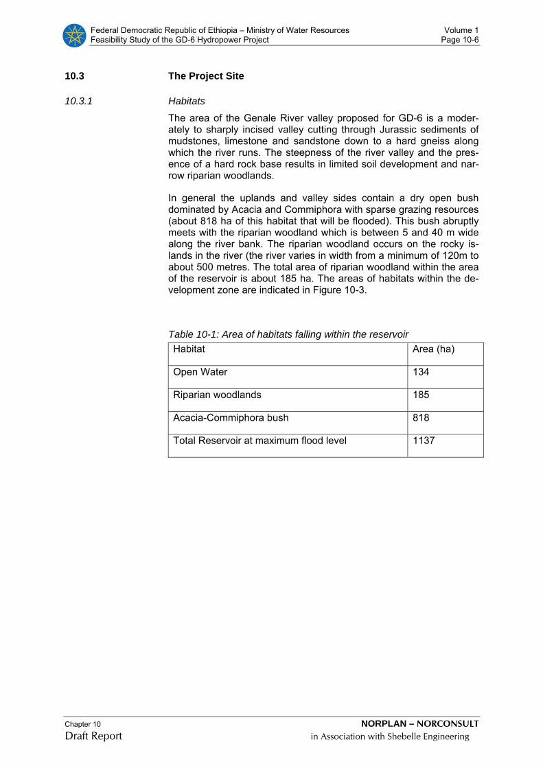
Federal Democratic Republic of Ethiopia – Ministry of Water Resources Volume 1 Feasibility Study of the GD-6 Hydropower Project Page 10-6
Chapter 10 NORPLAN – NORCONSULT Draft Report in Association with Shebelle Engineering
10.3 The Project Site
10.3.1 Habitats
The area of the Genale River valley proposed for GD-6 is a moder-ately to sharply incised valley cutting through Jurassic sediments of mudstones, limestone and sandstone down to a hard gneiss along which the river runs. The steepness of the river valley and the pres-ence of a hard rock base results in limited soil development and nar-row riparian woodlands.
In general the uplands and valley sides contain a dry open bush dominated by Acacia and Commiphora with sparse grazing resources (about 818 ha of this habitat that will be flooded). This bush abruptly meets with the riparian woodland which is between 5 and 40 m wide along the river bank. The riparian woodland occurs on the rocky is-lands in the river (the river varies in width from a minimum of 120m to about 500 metres. The total area of riparian woodland within the area of the reservoir is about 185 ha. The areas of habitats within the de-velopment zone are indicated in Figure 10-3.
Table 10-1: Area of habitats falling within the reservoir Habitat Area (ha)
Open Water 134
Riparian woodlands 185
Acacia-Commiphora bush 818
Total Reservoir at maximum flood level 1137

Federal Democratic Republic of Ethiopia – Ministry of Water Resources Volume 1 Feasibility Study of the GD-6 Hydropower Project Page 10-7
Chapter 10 NORPLAN – NORCONSULT Draft Report in Association with Shebelle Engineering
5 0 5 Kilometers
N
EW
S
Meda River
ContoursGenale RiverMax flood level 600mHigh WL 585mOpen waterRiparian Woodland
Habitats WithinGD6 Reservoir
#
Maximum flood level
#
Operational highwater level
#
Genale River and woodland 120-500mwide
#
Dam wall
Figure 10-3: Major habitats within GD-6 reservoir
Table 10-2: Area of habitats between theGD-6 dam wall and the Meda River and between the Meda river and the tailrace outlet Habitat Area (ha)
Open Water (Dam wall to Meda River) 82
Open Water (Meda River to tailrace) 175
Riparian woodlands (Dam wall to Meda River) 66
Riparian woodlands (Meda River to tailrace) 80

Federal Democratic Republic of Ethiopia – Ministry of Water Resources Volume 1 Feasibility Study of the GD-6 Hydropower Project Page 10-8
Chapter 10 NORPLAN – NORCONSULT Draft Report in Association with Shebelle Engineering
10.3.2 Settlement
No permanent settlement was found within the proposed reservoir area or immediately downstream. This does not mean that the area is not used on a seasonal or occasional basis. Use of the area is par-tially in response to drought conditions there are temporary camps for pastoralists. The maximum number of temporary sites (past and pre-sent) utilised by pastoralists within the reservoir area is 22, with a fur-ther 13 between the dam wall and the outlet from the tailrace that will not be inundated.
"A
#Y
A
"A
"A
#Y"A
#
Negele
#
Filtu
Oromia Region, Bale ZoneMeda Welabu Werede
Somali Region, Liben ZoneLiben Werede
Oromia Region, Bore ZoneLiben Werede
#
Genale catchment below GD3
#
GD3Dam Site
Genale River and zone border
#
Siru
Haydimtu Kebele(downstream of
reservoir)Siru Kebele(reservoir)
Dibi Kebele(upper reservoir)
Meda Kebele(left bank)
#
Bitata
#
GD6 reservoir
N
EW
S
Location of AdministrativeUnits
50 0 50 Kilometers
Figure 10-4: Location of administrative units affected by GD-6
10.3.3 Arable Agriculture
The survey of the DIZ located three areas of arable agriculture, one of which is irrigated. These are indicated in Figure 10-5.
The irrigated agriculture covers an area of 0.9 ha and lies approxi-mately 2.2 km downstream of the proposed dam wall. The owner (Mr Gemale) stays in Haydimtu Kebele which is about 50km away and three people work on the lands area during the crop production sea-son. Water is pumped via a diesel water pump into a furrow to flood

Federal Democratic Republic of Ethiopia – Ministry of Water Resources Volume 1 Feasibility Study of the GD-6 Hydropower Project Page 10-9
Chapter 10 NORPLAN – NORCONSULT Draft Report in Association with Shebelle Engineering
irrigate the arable lands area. The key crops produced are maize, sorghum, onions, tomato, pawpaw, melon and beans (soy and hari-cot).
###
#
##
#####
#
##
##
# # ##
#
#
# ##
###
#
N
EW
S
3 0 3 Kilometers
Meda River
#
GD6 wall
Rivers and streamsMax flood level 600mHigh WL 585mOpen water
# Pastoralists camps
Arable agricultureIrrigated agricultureRecession agriculture
Arable Agriculture
Figure 10-5: Areas of arable agriculture within the site
There are other arable areas based on recession agriculture called Jerdere which is farmed by two families from Sifu kebele located within the reservoir area. The main crops grown are; maize and on-ion. The field survey identified an area of riverbank of approximately 1.6 ha which appears to have been cleared in 2008 for arable agricul-ture as a thorn fence protects the area from livestock.
In general there are few areas of suitable alluvial soils for agriculture to take place in the Genale river valley and the proposed project res-ervoir will only affect two recession agricultural areas of about 10.6 ha.
Federal Democratic Republic of Ethiopia – Ministry of Water Resources Volume 1 Feasibility Study of the GD-6 Hydropower Project Page 10-10
Chapter 10 NORPLAN – NORCONSULT Draft Report in Association with Shebelle Engineering
10.3.4 Livestock Production
Livestock production in the Genale river valley is constrained by low rainfall and the presence of Tsetse Fly which transmit a fatal livestock disease to domestic stock.
During drought years, when water resources in the Dawa River and other traditional watering points dry up, pastoralists move to the Genale River in search of water and grazing. As indicated in the set-tlement section, a maximum of 22 temporary livestock sites have been identified within the reservoir area on the right bank and 13 in the area between the dam wall and the tailrace (also predominantly on the right bank).
The main types of livestock are sheep and goats that are brought into the area on a seasonal basis (which tend to rely on the riparian wood-land). Cattle and camels are also brought into the area but in low numbers due to the presence of Tsetse Fly. The cattle and camels are not kept near the river and tend to graze on the highlands, simply entering the area for water. Camels use browse that is cut from the riparian woodlands.
Major livestock diseases near the river are Anthrax, tick borne dis-eases, abagorba, (Ngana) and livestock intestinal diseases.
The amount of grazing lost through flooding of the reservoir will be about 818 ha. Although the reservoir will not reduce access to water, it will mean the loss of riparian woodland grazing on the right bank. Stock and people do not make much use of the islands within the river due to the presence of crocodile. Average tropical livestock units (TLU) for Liben zone is 52/km2 (GDMP, 2006).
10.3.5 Other Land Uses and Natural Resources
During the social surveys, people who have used the river valley dur-ing the recent past were asked to outline their use of river and river-ine resources.
During the field survey it was observed that the greatest impacts to riparian vegetation came from clearing and fire for arable lands and collecting of materials for stock bomas. Livestock grazing into the ri-parian was also opening up the narrow woodland.
Federal Democratic Republic of Ethiopia – Ministry of Water Resources Volume 1 Feasibility Study of the GD-6 Hydropower Project Page 10-11
Chapter 10 NORPLAN – NORCONSULT Draft Report in Association with Shebelle Engineering
10.4 Potential Environmental and Social Impacts
GD-6 will operate largely as a run-of-river plant with the regulated flow from GD-3 being diverted through the power house. Thus, during normal operation periods the stretch of river between the dam wall and the inflow of the Meda River (5.1km) will only have much reduced flows except when GD-3 and subsequently GD-6 spills and a flood occurs. There is no commercial fishery on Genale River in the vicinity of the dam site. However, some individuals catch fish for household purposes and for small scale trading at nearby towns.
Assuming regulation of the Genale River by the upstream GD-3 res-ervoir then the incremental effects on the flow regime of adding the GD-6 to the cascade are minimal. No especially unique habitats fall within the reservoir area and apart from the narrow belt of riverine vegetation biomass is low and the area is used mostly for occasional grazing with very small patches (10ha) of recession type agriculture.
There is no permanent settlement in the reservoir area and no reset-tlement requirements attached to the project. No roads or other public infrastructure is located within the direct impact zone of the project. A few (22) temporary/seasonal pastoralist camps exist in the area and mitigation will need to be considered for temporary grazing areas in-undated.
Virtually all major impacts are associated with the influx of labour and the provision of road access to the area during the construction phase. Although there are no communities in the immediate vicinity of the project, any development will cause secondary impacts in the wider area in terms of social and health changes and opportunities for economic and commercial livelihood. Additional pressure on the riv-erine habitat downstream of the project may be anticipated through improved access also.
Overall, however, with effective environmental management planning and an efficient monitoring regime any negative impacts should be capable of being controlled to acceptable levels. The limited impact profile of the GD-6 project results in environmental costs not being high.
10.5 Irrigation and Downstream Issues
10.5.1 Irrigation in GD-6 Basin
At the reservoir site the Genale is deeply incised and the tributary streams fall steeply to the Genale. Around the reservoir there are no areas of land with deep soils and moderate gradients which would be suitable for irrigation.
The Genale Dawa Master Plan Study carried out an assessment of all the potential irrigation projects that have been identified in the Genale Dawa Basin. The original long list of 93 projects with a total area of 1,074,720ha was reduced to a short list of 10 projects with a total area of 59,000ha. None of these 10 short listed projects is in the GD-
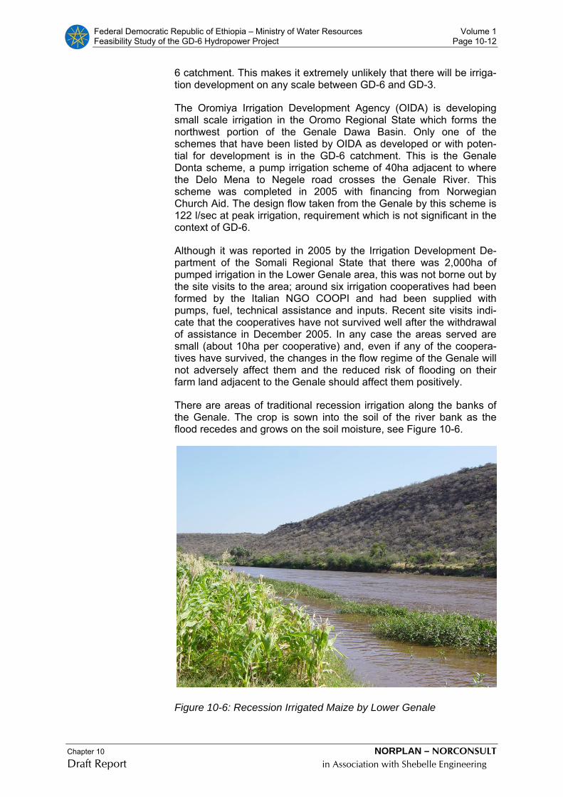
Federal Democratic Republic of Ethiopia – Ministry of Water Resources Volume 1 Feasibility Study of the GD-6 Hydropower Project Page 10-12
Chapter 10 NORPLAN – NORCONSULT Draft Report in Association with Shebelle Engineering
6 catchment. This makes it extremely unlikely that there will be irriga-tion development on any scale between GD-6 and GD-3.
The Oromiya Irrigation Development Agency (OIDA) is developing small scale irrigation in the Oromo Regional State which forms the northwest portion of the Genale Dawa Basin. Only one of the schemes that have been listed by OIDA as developed or with poten-tial for development is in the GD-6 catchment. This is the Genale Donta scheme, a pump irrigation scheme of 40ha adjacent to where the Delo Mena to Negele road crosses the Genale River. This scheme was completed in 2005 with financing from Norwegian Church Aid. The design flow taken from the Genale by this scheme is 122 l/sec at peak irrigation, requirement which is not significant in the context of GD-6.
Although it was reported in 2005 by the Irrigation Development De-partment of the Somali Regional State that there was 2,000ha of pumped irrigation in the Lower Genale area, this was not borne out by the site visits to the area; around six irrigation cooperatives had been formed by the Italian NGO COOPI and had been supplied with pumps, fuel, technical assistance and inputs. Recent site visits indi-cate that the cooperatives have not survived well after the withdrawal of assistance in December 2005. In any case the areas served are small (about 10ha per cooperative) and, even if any of the coopera-tives have survived, the changes in the flow regime of the Genale will not adversely affect them and the reduced risk of flooding on their farm land adjacent to the Genale should affect them positively.
There are areas of traditional recession irrigation along the banks of the Genale. The crop is sown into the soil of the river bank as the flood recedes and grows on the soil moisture, see Figure 10-6.
Figure 10-6: Recession Irrigated Maize by Lower Genale
Federal Democratic Republic of Ethiopia – Ministry of Water Resources Volume 1 Feasibility Study of the GD-6 Hydropower Project Page 10-13
Chapter 10 NORPLAN – NORCONSULT Draft Report in Association with Shebelle Engineering
The regulation of the flow in the Genale by GD-3 will reduce the varia-tion in water level between high flow and low flow and will, therefore, reduce the potential for this type of cultivation.
The total area of recession irrigation is likely to be small, there are not a great number of localities that are suitable, however recession irri-gation may be important to individual families but the regulation of water here is not controlled by GD-6.
10.5.2 Irrigation Potential Downstream of GD-6
The only area in Ethiopia downstream of GD-6, which has potential for irrigation development, is the Lower Genale Irrigation Project (LGIP), which is located between Dolo Odo, on the border to Somalia, and the town of Kole.
A pre-feasibility study for this project was carried out in 2005 which gave an EIRR for the project of 2%. A feasibility study, the draft of which was completed in November 2008, used less conservative as-sumptions than the pre-feasibility study and gave an EIRR of 7.3%. These low EIRRs do not make it likely that this project will attract in-ternational finance.
In any case the LGIP pre-feasibility study found that the impact of the regulation of the GD-3 hydropower project was not very significant; the timing and duration of two annual crops can be arranged to coin-cide with the double peaked annual hydrograph of the unregulated river.
The increased dry season flows resulting from regulation of the Genale by the GD-3 hydropower project would allow a slightly larger area of perennial crops to be grown on the project.
The GD-6 dam will provide minimal additional regulation of the Genale at the site of the LGIP diversion dam; the only perennial tribu-taries of the Genale downstream of GD-3, the Welmel River and the Wabe Mena, have their confluences with the Genale downstream of GD-6. The additional catchment of GD-6 over GD-3 lies in the Middle Basin and the tributaries are ephemeral; flowing during rainfall events but drying up shortly after the conclusion of the rainfall event.
10.5.3 Transboundary Issues
The Genale River is an “International Waterway”; it has its origin in one country, Ethiopia, and flows to another country, Somalia. The World Bank Operational Policy OP 6.50; “Projects on International Waterways”, is therefore triggered by projects on the Genale River.
OP 6.50 requires that, before any before any project can be imple-mented on an International Waterway, an agreement should be en-tered into by the riparian countries.
At the start of the rainy season, when storms in the Lower and Middle Basin may be expected to give high salinity runoff at a time when there is little natural flow from the Upper Basin, the regulated flow of
Federal Democratic Republic of Ethiopia – Ministry of Water Resources Volume 1 Feasibility Study of the GD-6 Hydropower Project Page 10-14
Chapter 10 NORPLAN – NORCONSULT Draft Report in Association with Shebelle Engineering
low salinity water from the reservoirs will serve to reduce the salinity of the cross border river flow.
During the rainy season the dams on the Genale will increase the sa-linity of the cross-border flow; in the rainy season the reservoirs will retain part of the low salinity water from the Upper Basin whilst the saline water from the Lower Basin will runoff to the rivers. The reduc-tion of the salinity of the river water at the start of the rainy season, when the salinity is too high, would be beneficial to downstream users whereas the increase in salinity during the remainder of the flood season may be beneficial in reducing the risk of infiltration problems.
Somalia has long sought to regulate the flow of the Juba River to pro-vide flood mitigation, irrigation development and hydropower. The planned Baardhere dam, just upstream of the town of the same name, was originally designed to irrigate up to 170,000ha, but the size of the planned dam was reduced, under pressure from potential financiers, to a size with sufficient storage to irrigate 50,000ha, to take account of the necessity of sharing of the water of the Genale/Juba with Ethiopia.
The construction of the GD-3 dam would provide some of the regula-tion required by Somalia and may obviate or substantially reduce the need for the Baardhere Dam; however the incremental effect of add-ing the GD-6 project would be minimal.
The regulation of the Genale/Juba River will reduce flooding. In Ethiopia there are few reports of serious flooding but in the Lower Juba Valley in Somalia there has been very serious flooding leading to loss of life, livestock and livelihood. The regulation by GD-3 may help to reduce the severity of this flooding but there is little effect ex-pected from GD-6.
10.5.4 Key Assumptions Made in the EIA
After the scoping phase to identify main issues associated with de-velopment of the GD-6 project the EIA study made a number of key assumptions for the study, namely:
1) GD-3 HPP upstream will regulate the river flow leaving GD-6 as a run-of-river project; i.e. any impacts associated with changes to the hydrological regime are captured by the GD-3 project
2) There are no permanent settlements at the GD-6 dam site or in the proposed reservoir area; i.e. no resettlement requirement for the pro-ject and no settled communities directly affected
3) The GD-3 dam will act as a silt trap for the upstream catchment and hence catchment erosion, sedimentation and land use issues are relevant only for the stretch between the GD-6 and the GD-3 dams
4) The EIA is a feasibility level document and the format chosen for the report is modelled on World Bank Group guidelines cross-referencing to ensure the main issues required by Ethiopian guide-lines are covered

Federal Democratic Republic of Ethiopia – Ministry of Water Resources Volume 1 Feasibility Study of the GD-6 Hydropower Project Page 10-15
Chapter 10 NORPLAN – NORCONSULT Draft Report in Association with Shebelle Engineering
5) Guiding Principle - the level of baseline study, impact analysis and mitigation recommendations should be commensurate with the de-gree of impact anticipated
The preceding discussion and assessment of impacts as well as the reporting has been done with reference to these key assumptions.
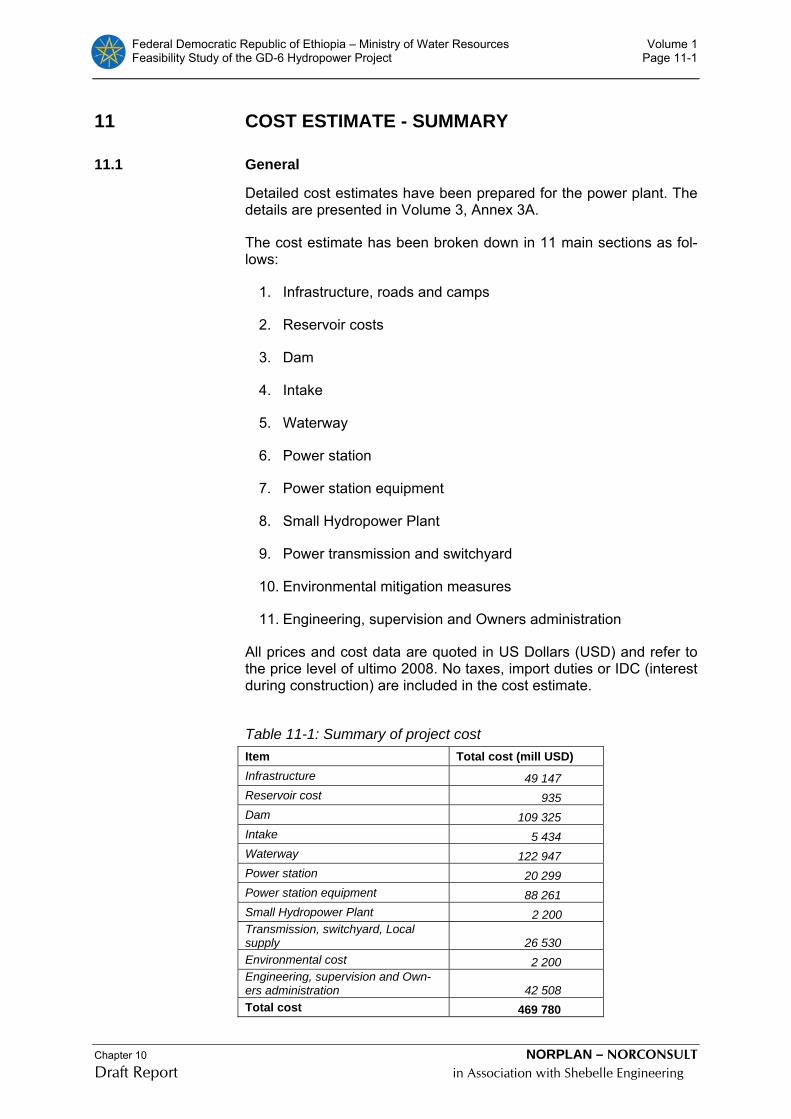
Federal Democratic Republic of Ethiopia – Ministry of Water Resources Volume 1 Feasibility Study of the GD-6 Hydropower Project Page 11-1
Chapter 10 NORPLAN – NORCONSULT Draft Report in Association with Shebelle Engineering
11 COST ESTIMATE - SUMMARY
11.1 General
Detailed cost estimates have been prepared for the power plant. The details are presented in Volume 3, Annex 3A.
The cost estimate has been broken down in 11 main sections as fol-lows:
1. Infrastructure, roads and camps
2. Reservoir costs
3. Dam
4. Intake
5. Waterway
6. Power station
7. Power station equipment
8. Small Hydropower Plant
9. Power transmission and switchyard
10. Environmental mitigation measures
11. Engineering, supervision and Owners administration
All prices and cost data are quoted in US Dollars (USD) and refer to the price level of ultimo 2008. No taxes, import duties or IDC (interest during construction) are included in the cost estimate.
Table 11-1: Summary of project cost Item Total cost (mill USD) Infrastructure 49 147 Reservoir cost 935 Dam 109 325 Intake 5 434 Waterway 122 947 Power station 20 299 Power station equipment 88 261 Small Hydropower Plant 2 200 Transmission, switchyard, Local supply 26 530 Environmental cost 2 200 Engineering, supervision and Own-ers administration 42 508 Total cost 469 780

Federal Democratic Republic of Ethiopia – Ministry of Water Resources Volume 1 Feasibility Study of the GD-6 Hydropower Project Page 11-2
Chapter 10 NORPLAN – NORCONSULT Draft Report in Association with Shebelle Engineering
Detailed cost disbursement schedules for the selected project is
given in Annex 3 G, and the summary below in Figure 11-1.
Figure 11-1: Cost distribution
11.2 Contract packages
It is assumed that most of the project will be implemented through international competitive bidding, and that the project will be split in a number of lots. On this basis the following major contract packages are assumed:
• 33 kV transmission line
• Camp construction
• Civil works, dam, power station, waterways and roads
• Electro-mechanical works.
• 400 kV transmission lines and sub-station
The mobilisation for the main contractor is scheduled to start with mi-nor upgrading of the existing track, and with major transport require-ment before the main access is completed, it is advised to have the road contract as part of the main contract.
11.3 Labour and construction equipment
The cost estimate and the construction schedule have been prepared based upon the assumption that the civil works construction will be carried out by modern construction techniques, using heavy construc-tion plant.
Cost of all equipment and labour are included in the unit prices.
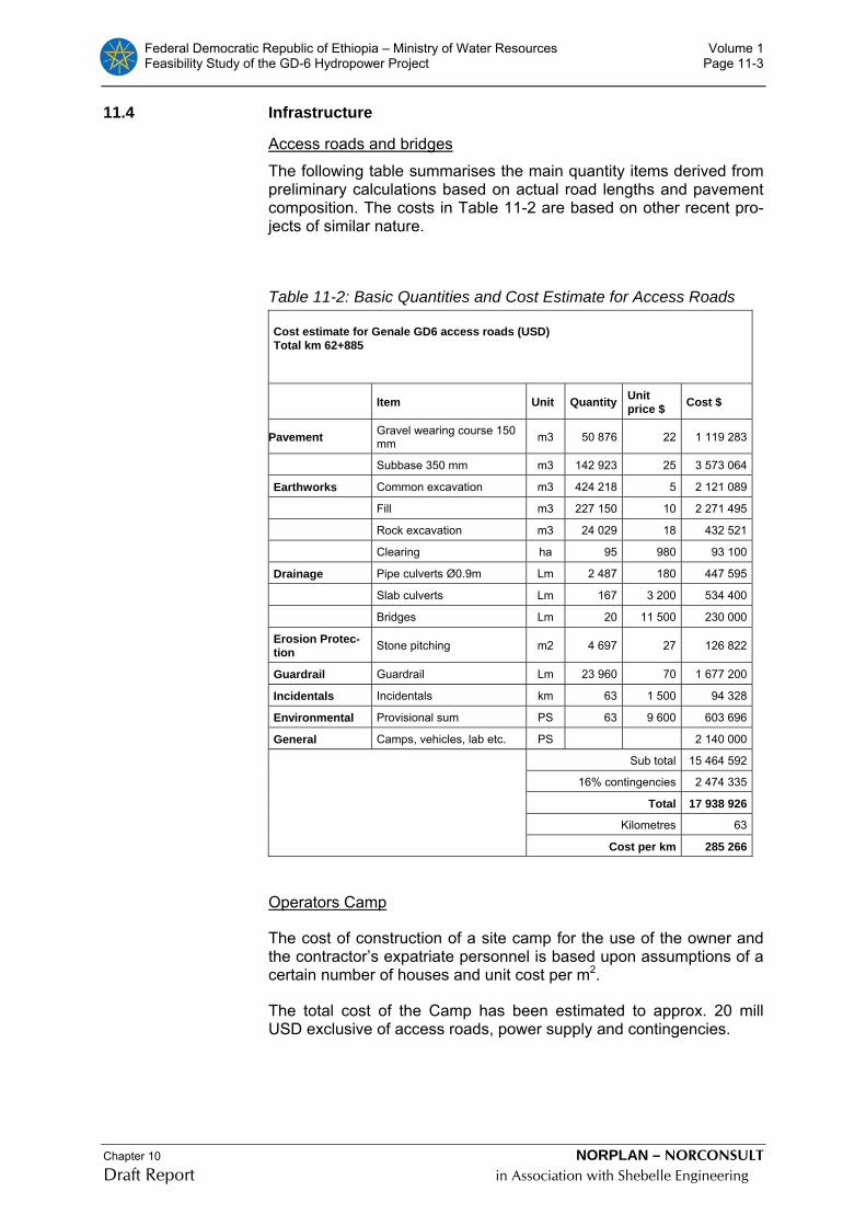
Federal Democratic Republic of Ethiopia – Ministry of Water Resources Volume 1 Feasibility Study of the GD-6 Hydropower Project Page 11-3
Chapter 10 NORPLAN – NORCONSULT Draft Report in Association with Shebelle Engineering
11.4 Infrastructure
Access roads and bridges
The following table summarises the main quantity items derived from preliminary calculations based on actual road lengths and pavement composition. The costs in Table 11-2 are based on other recent pro-jects of similar nature.
Table 11-2: Basic Quantities and Cost Estimate for Access Roads Cost estimate for Genale GD6 access roads (USD) Total km 62+885
Item Unit Quantity Unit price $ Cost $
Pavement Gravel wearing course 150 mm m3 50 876 22 1 119 283
Subbase 350 mm m3 142 923 25 3 573 064
Earthworks Common excavation m3 424 218 5 2 121 089
Fill m3 227 150 10 2 271 495
Rock excavation m3 24 029 18 432 521
Clearing ha 95 980 93 100
Drainage Pipe culverts Ø0.9m Lm 2 487 180 447 595
Slab culverts Lm 167 3 200 534 400
Bridges Lm 20 11 500 230 000
Erosion Protec-tion Stone pitching m2 4 697 27 126 822
Guardrail Guardrail Lm 23 960 70 1 677 200
Incidentals Incidentals km 63 1 500 94 328
Environmental Provisional sum PS 63 9 600 603 696
General Camps, vehicles, lab etc. PS 2 140 000
Sub total 15 464 592
16% contingencies 2 474 335
Total 17 938 926
Kilometres 63
Cost per km 285 266
Operators Camp
The cost of construction of a site camp for the use of the owner and the contractor’s expatriate personnel is based upon assumptions of a certain number of houses and unit cost per m2.
The total cost of the Camp has been estimated to approx. 20 mill USD exclusive of access roads, power supply and contingencies.

Federal Democratic Republic of Ethiopia – Ministry of Water Resources Volume 1 Feasibility Study of the GD-6 Hydropower Project Page 11-4
Chapter 10 NORPLAN – NORCONSULT Draft Report in Association with Shebelle Engineering
11.5 Cost of power plant civil works
11.5.1 General
The cost estimates for civil works are based upon quantities for the major project items and the unit rates for these items.
A list of the main unit rates adopted for costing of the project is given in Table 11-5 below.
In order to establish the list of unit rates of civil works, the Consultant has used cost from other projects in Africa and internationally as a basis. These unit prices have been adjusted in accordance with in-formation obtained on international contractors’ prices given under competition for the Gilgil-Gibe and Tekeze hydropower plants in Ethiopia. The unit rates in the unit rate table include all direct costs including purchase costs of construction plant, the operation and maintenance cost and the relevant portions of site installations. The contractor’s preliminaries and general costs amounting to 15-25% of direct cost for the dam and the power plant work are added in the summary. The contractor's preliminaries and general costs includes the contractor’s mobilisation, operation of camp and offices, insur-ances and bonds, international transports and air freight, site admini-stration, travel cost for expatriates, profit and parts of the site installa-tions not included in the direct costs for the various items.
One of the major costs in the project is the tunnel boring machine (TBM) and operation of the TBM. The general cost related to TBM is normally higher than the 25 % used in the summary, but the major part of the TBM depreciation and procurement cost is included in the unit rates, as described below in 11.5.3.
It is further assumed that most of the other heavy construction plant tunnelling equipment and the heavy concrete batching, mixing and transportation plant have to be brought into the country.
11.5.2 Surface excavation works
Outdoor rock and soil excavation has been split into two rates, smaller confined excavations where care has to be taken due to sub-sequent concrete works or other treatment works, and larger soil or rock excavations as necessary for the intake area, dam foundation areas etc.
11.5.3 Cost estimate-TBM
The cost estimates are established as functions of many parameters, as TBM diameter, machine specifications, machine prices and depre-ciation, boring lengths, rock mass drilling properties and assumed rock support and grouting quantities.
The estimates are based on prices and information supplied from machine suppliers (price of new machines, rest value, drilling and cut-ter costs, etc.), from contractors (running and staffing costs, repair costs), and experience from several projects. All figures in Mill. USD as per 01.01.2009.

Federal Democratic Republic of Ethiopia – Ministry of Water Resources Volume 1 Feasibility Study of the GD-6 Hydropower Project Page 11-5
Chapter 10 NORPLAN – NORCONSULT Draft Report in Association with Shebelle Engineering
Table 11-3: Cost estimate - TBM Cost element Tailrace tunnel,
11.20 km Headrace tun-nel, 4.74 km *
Headrace+tailrace tunnel, 15,94 km
Transport to site, according to Robbins 1 700 000 1 700 000 1 700 000 TBM, back up and conveyor 26 160 000 23 300 000 29 600 000 Labour force, local and expatriate 5 330 000 2 420 000 7 540 000 Cutter, spare parts, acc. to Robbins 12 820 000 5 430 000 18 250 000 Other materials (cable, vent, light etc.) 730 000 300 000 970 000 Invert filling 520 000 220 000 690 000 Other machinery in tunnels 1 570 000 700 000 2 210 000 Shifting of TBM from headrace to tail-race
1 000 000
Total net cost 48 830 000 34 070 000 61 960 000 Net tunnel cost per m USD 4 360 7 188 3 887 Site installations, general costs, site overhead administration and profit, 25%
12 207 500 8 517 500 15 490 000
Total cost estimate, see assumptions below
61 037 500 42 587 500 77 450 000
Cost per tunnel meter, USD 5 450 8 985 4 858 *Cost if drilled with TBM no. 2.
The following cost elements are included in the cost estimates:
• Transport of all necessary equipment to and from site • Mobilisation necessary for excavating and supporting the tun-
nel • Assembly and disassembly of TBM, back up and other equip-
ment • All costs related to personnel for performing the tunnel boring,
rock support, groundwater treatment, etc • Cost for machines and equipment, for the different alterna-
tives, updated according to Robbins Company • Depreciation rate, anticipated to
o 70% for short sections (<7000 m) o 80% for long sections (7000-14000 m) o 90% for long sections (>14000 m)
• All consumable spare parts • Ventilation, dewatering, electrical cables and light in the tun-
nels • Invert segments or in situ invert concrete where rubber tyre
vehicles are adopted • Transport of the excavated material to deposit outside the
tunnel portals, with a distance of 500 m • Some handling and transport of the excavated material on the
deposit and to final destination • Contractor general costs, site overhead, administration and
profit are included with 25%
Elements not included are:
• Rock support and lining • Access roads and preparation of site mobilisation area • Excavation of access tunnels and launching chambers

Federal Democratic Republic of Ethiopia – Ministry of Water Resources Volume 1 Feasibility Study of the GD-6 Hydropower Project Page 11-6
Chapter 10 NORPLAN – NORCONSULT Draft Report in Association with Shebelle Engineering
• Transport of spoils in excess of some 500 m from the tunnel entrance
• Treatment plant for tunnel discharge water (if necessary) • Contingencies • All client related costs, including right of land, financing, design
and supervision
As indicated in the table above, the tunnel costs are highly dependant on the investment cost and depreciation of the TBM. New TBM ma-chine and high depreciation amount are included in the estimate pre-sented above.
The GD-6 tunnel excavation could be drilled by one TBM, and the unit price used is rounded up to:
- 3900 USD/m
Used and refurbished machines could be applied at the projects, if available at tender stage, and could result in lower prices for TBM ex-cavated tunnels.
11.5.4 Cost estimates – Drill & Blast Waterway
The excavation cost for a tunnel is normally given by the formula:
P = C + K * A USD/m
C and K are constants, and A is the theoretically excavated area. K is the marginal excavation rate and is set to 21 USD/m3. The described cost formula normally applies to all cross-sections above 30 m2 and has been used in order to arrive at the basic tunnel costs for different tunnel diameters.
Rock support cost of the tunnels has been estimated separately de-pending upon the use of the tunnel, the size of the tunnel and the rock mass quality along the tunnel route. The temporary support work will generally comprise grouted rock bolts and fibre reinforced shot-crete.
The final evaluation has been made based on average international production rates and prices according to in-house data and informal discussions with contractors. All cost data has been collected and analyzed in the USD currency.
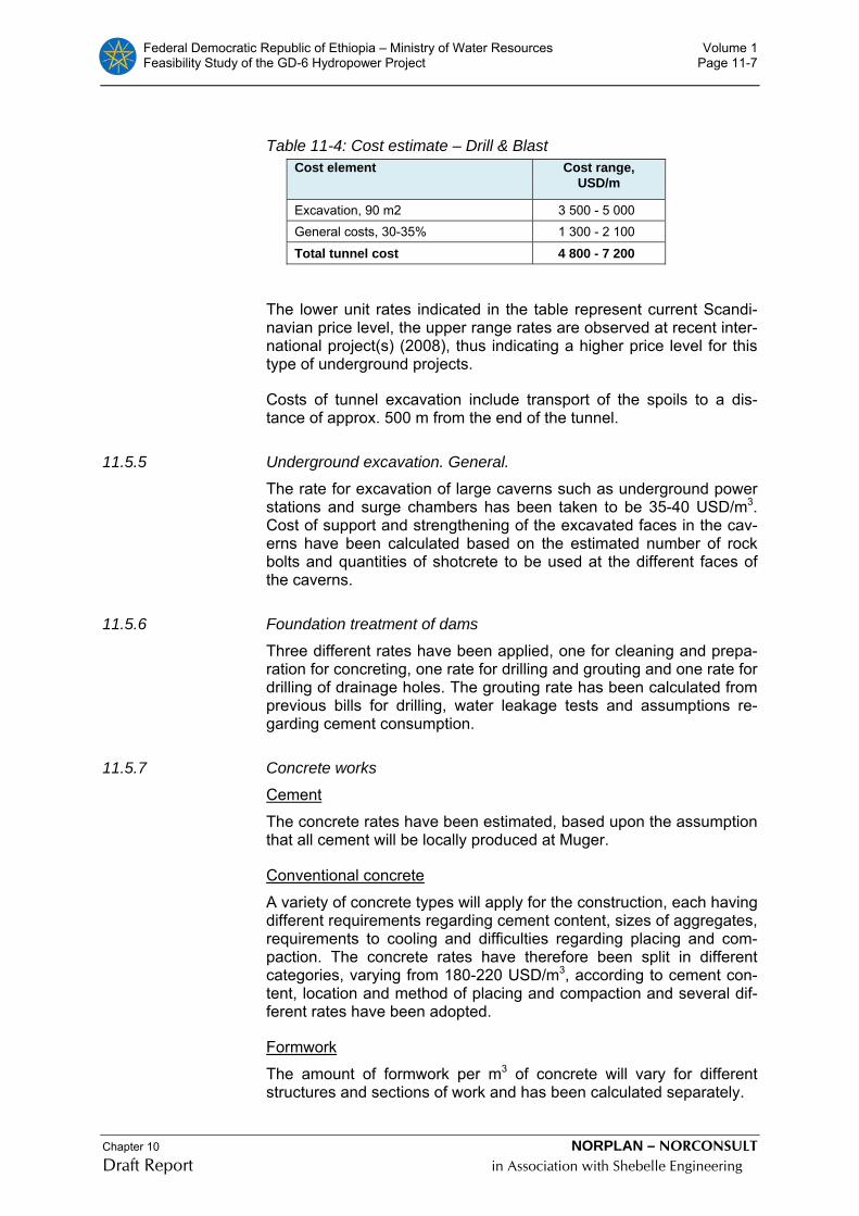
Federal Democratic Republic of Ethiopia – Ministry of Water Resources Volume 1 Feasibility Study of the GD-6 Hydropower Project Page 11-7
Chapter 10 NORPLAN – NORCONSULT Draft Report in Association with Shebelle Engineering
Table 11-4: Cost estimate – Drill & Blast Cost element Cost range,
USD/m
Excavation, 90 m2 3 500 - 5 000 General costs, 30-35% 1 300 - 2 100
Total tunnel cost 4 800 - 7 200
The lower unit rates indicated in the table represent current Scandi-navian price level, the upper range rates are observed at recent inter-national project(s) (2008), thus indicating a higher price level for this type of underground projects.
Costs of tunnel excavation include transport of the spoils to a dis-tance of approx. 500 m from the end of the tunnel.
11.5.5 Underground excavation. General.
The rate for excavation of large caverns such as underground power stations and surge chambers has been taken to be 35-40 USD/m3. Cost of support and strengthening of the excavated faces in the cav-erns have been calculated based on the estimated number of rock bolts and quantities of shotcrete to be used at the different faces of the caverns.
11.5.6 Foundation treatment of dams
Three different rates have been applied, one for cleaning and prepa-ration for concreting, one rate for drilling and grouting and one rate for drilling of drainage holes. The grouting rate has been calculated from previous bills for drilling, water leakage tests and assumptions re-garding cement consumption.
11.5.7 Concrete works
Cement
The concrete rates have been estimated, based upon the assumption that all cement will be locally produced at Muger.
Conventional concrete
A variety of concrete types will apply for the construction, each having different requirements regarding cement content, sizes of aggregates, requirements to cooling and difficulties regarding placing and com-paction. The concrete rates have therefore been split in different categories, varying from 180-220 USD/m3, according to cement con-tent, location and method of placing and compaction and several dif-ferent rates have been adopted.
Formwork
The amount of formwork per m3 of concrete will vary for different structures and sections of work and has been calculated separately.

Federal Democratic Republic of Ethiopia – Ministry of Water Resources Volume 1 Feasibility Study of the GD-6 Hydropower Project Page 11-8
Chapter 10 NORPLAN – NORCONSULT Draft Report in Association with Shebelle Engineering
Four different formwork rates have been adopted to reflect the diffi-culty of the formwork, outdoor crane handled formwork, under ground formwork in the powerhouse, lining formwork in tunnels and lining formwork in the shafts.
Reinforcement
For reinforcement one rate has been applied to all sections of work.
11.5.8 Unit rates
The main unit rates used for cost estimates of the civil works are given in Table ¨Table 11-5 below. Other rates are given in the de-tailed cost estimate in Annex K.
Table 11-5 Unit rates Civil Works INFRASTRUCTURE WORKS UNIT Local Foreign
code Road works Rate USD cost cost
A08 Road maintenance lm / year 12 80 % 20 %A09 Asphalt surfacing m2 20 60 % 40 %A10 Cement bonded road surface treatment m2 15 70 % 30 %A20 Clearing ha 980 80 % 20 %A21 Common excavation m3 5 80 % 20 %A22 Fill m3 10 80 % 20 %A23 Rock excavation m3 18 80 % 20 %A24 Gravel wearing course 150 mm m3 22 80 % 20 %A25 Subbase 350 mm m3 25 80 % 20 %A26 Erosion protection m2 27 80 % 20 %A27 Guard rail lm 70 70 % 30 %
CONCRETE WORKS Outdoor
C01 Plain vertical formwork m2 60 70 % 30 %C02 Plain sloping formwork m2 80 70 % 30 %C03 Plain horizontal formwork m2 80 70 % 30 %C04 Curved formwork m2 100 70 % 30 %C06 Mass concrete m3 120 70 % 30 %C10 Structural concrete C35 outdoor m3 180 70 % 30 %C14 Reinforcement steel ton 2 000 70 % 30 %
Underground C21 Formwork to tunnel lining m2 80 70 % 30 %C22 Formwork to shaft lining m2 110 70 % 30 %C24 Plain vertical formwork UG m2 70 70 % 30 %C25 Plain horizontal formwork UG m2 90 70 % 30 %C26 Plain curved formwork UG m2 110 70 % 30 %C27 Sliding/climbing formwork UG m2 50 70 % 30 %C28 Mass Concrete UG m3 140 70 % 30 %C29 Concrete in tunnel lining C35 m3 220 70 % 30 %C30 Concrete in shaft lining C35 m3 220 70 % 30 %C31 Concrete in tunnel slab C35 m3 150 70 % 30 %C32 Structural concrete C35 UG m3 200 70 % 30 %C34 Reinforcement steel ton 2 050 50 % 50 %
DAM WORKS Foundation preparation for dams
D02 Foundation preparation for dams m2 8 40 % 60 %D03 Drilling and grouting lm 150 25 % 75 %D06 Grout curtain m2 100 20 % 80 %
Earth and Rock fill dam D10 Asphalt core m3 380 20 % 80 %D12 Filter fill, crushed rock, (D=0-60 mm, T= 1.5m) m3 23 40 % 60 %D13 Filter fill, crushed rock, (D=0-20 mm, T= 0,2m) m3 23 40 % 60 %D14 Transition fill (D=0-150 mm, T=1.0 m) m3 15 40 % 60 %D15 Transition fill (D=0-200 mm, T=4.0 m) m3 15 40 % 60 %D16 Rock fill (D=0-0.3m) m3 13 40 % 60 %D17 Rock fill drainage layer(D=0.03-0.2m) m3 15 40 % 60 %D18 Rock fill,D=0-0.6m m3 12 40 % 60 %

Federal Democratic Republic of Ethiopia – Ministry of Water Resources Volume 1 Feasibility Study of the GD-6 Hydropower Project Page 11-9
Chapter 10 NORPLAN – NORCONSULT Draft Report in Association with Shebelle Engineering
D19 Rock fill, D=0-1.0 m m3 10 40 % 60 %D20 Rock fill from excavations m3 8 40 % 60 %D21 Rip-Rap slope protection m3 15 40 % 60 %D23 Transport / haulage m3-km 1.0 70 % 30 %D24 Rip-Rap toe protection m3 25 40 % 60 %D26 Instrumentation % 1 10 % 90 %
Spillway D30 Formwork, plain m2 45 0 % 100 %D31 Formwork, sloping m2 50 0 % 100 %D32 Formwork, curved m2 60 0 % 100 %D37 Concrete in Spillway m3 180 0 % 100 %
EXCAVATION WORKS Open air
E04 Clearing and grubbing m2 2 30 % 70 %E05 Stripping of topsoil m2 4 30 % 70 %E06 Soft excavation (easy) m2 4 50 % 50 %E07 Soft excavation (normal) m3 6 50 % 50 %E08 Soft excavation (difficult) m3 8 50 % 50 %E09 Soft excavation (under water) m3 15 50 % 50 %E10 Rock excavation (easy/bulk) m3 8 50 % 50 %E11 Rock excavation (normal) m3 15 50 % 50 %E12 Rock excavation (structural) m3 17 50 % 50 %E13 Rock excavation (under water) m3 40 50 % 50 %E14 Rock excavtion dam foundation m3 27 50 % 50 %E15 Rock excavation, contour requirment m3 27 50 % 50 %E16 Contour drilling lm 5 50 % 50 %E17 Rock quarrying m3 3 40 % 60 %E18 Stabilising rock slopes m2 40 50 % 50 %E19 Stabilising earth slopes m2 10 50 % 50 %E20 Back fill and compact, excav. material m2 3 50 % 50 %E21 Back fill and compact, selec. material m3 5 50 % 50 %E22 Cofferdam fill m3 10 50 % 50 %E24 Rip-Rap protection river bed and slopes m3 22 70 % 30 %
Rock support E30 Rockbolts grouted, L=3m No 75 40 % 60 %E31 Rockbolts grouted, L=4 m No 150 40 % 60 %E32 Rockbolts grouted, L=6 m No 300 40 % 60 %E33 Rock achors, L= 10 m No 320 40 % 60 %E34 Shotcrete m3 400 35 % 65 %E35 Shotcrete with fiber m3 500 35 % 65 %E36 Cement grouting ton 1400 60 % 40 %E37 Polyurethane grouting kg 15 20 % 80 %E38 Wire mesh ton 2500 30 % 70 %
UNDERGROUND EXCAVATION E40 Excavation of cavern. General m3 35 35 % 65 %E41 Excavation of cavern. Top stoll m3 40 35 % 65 %E42 Smooth blasting m2 15 35 % 65 %E43 Excavation of shaft A=5m2, lm 1 400 35 % 65 %E44 Excavation of shaft A=10 m2, lm 2 200 35 % 65 %E45 Excavation of shaft A=20 m2, lm 3 200 35 % 65 %E46 Excavation of shaft A=30 m2, lm 4 200 35 % 65 %E49 Widening of shaft (additional m2) m3 110 35 % 65 %E51 Excavation of tunnel A=16m2, lm 1 900 35 % 65 %E52 Excavation of tunnel A=20 m2, lm 2 050 35 % 65 %E53 Excavation of tunnel A=25m2, lm 2 200 35 % 65 %E57 Excavation of tunnel A=50 m2, lm 2 860 35 % 65 %E61 Excavation of tunnel A=90 m2, lm 3 700 35 % 65 %E63 Marginal tunnel excavation m3 21 35 % 65 %E64 Cleaning tunnel invert m2 10 35 % 65 %E65 Pressure grouting of tunnel m 1 000 35 % 65 %
Rock support underground E70 Shotcrete with fiber, at face m3 500 30 % 70 %E71 Shotcrete with fibers m3 450 30 % 70 %E73 Shotcrete with fiber in shafts m3 700 30 % 70 %E75 Rockbolts grouted, L=3m No 80 25 % 75 %E77 Rockbolts grouted, L=4 m No 90 25 % 75 %E78 Rockbolts grouted, L=6 m No 100 25 % 75 %E79 Spiling rockbolt, L=6m grouted No 160 25 % 75 %E80 Rockbolts in shaft, grouted, L=3m No 120 25 % 75 %E81 Steel arch sets ton 4 000 20 % 80 %E84 Grouting of plug LS 80000 50 % 50 %E98 Excavation of TBM tunnel D=8 m lm 4 180 20 % 80 %
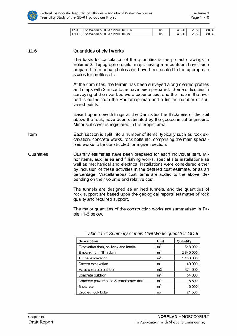
Federal Democratic Republic of Ethiopia – Ministry of Water Resources Volume 1 Feasibility Study of the GD-6 Hydropower Project Page 11-10
Chapter 10 NORPLAN – NORCONSULT Draft Report in Association with Shebelle Engineering
E99 Excavation of TBM tunnel D=8.5 m lm 4 390 20 % 80 %E100 Excavation of TBM tunnel D=9 m lm 4 600 20 % 80 %
11.6 Quantities of civil works
The basis for calculation of the quantities is the project drawings in Volume 2. Topographic digital maps having 5 m contours have been prepared from aerial photos and have been scaled to the appropriate scales for profiles etc.
At the dam sites, the terrain has been surveyed along cleared profiles and maps with 2 m contours have been prepared. Some difficulties in surveying of the river bed were experienced, and the map in the river bed is edited from the Photomap map and a limited number of sur-veyed points.
Based upon core drillings at the Dam sites the thickness of the soil above the rock, have been estimated by the geotechnical engineers. Minor soil cover is registered in the project area.
Item Each section is split into a number of items, typically such as rock ex-cavation, concrete works, rock bolts etc. comprising the main special-ised works to be constructed for a given section.
Quantities Quantity estimates have been prepared for each individual item. Mi-nor items, auxiliaries and finishing works, special site installations as well as mechanical and electrical installations were considered either by inclusion of these activities in the detailed cost estimate, or as an percentage. Miscellaneous cost items are added to the above, de-pending on their volume and relative cost.
The tunnels are designed as unlined tunnels, and the quantities of rock support are based upon the geological reports estimates of rock quality and required support.
The major quantities of the construction works are summarised in Ta-ble 11-6 below.
Table 11-6: Summary of main Civil Works quantities GD-6
Description Unit Quantity Excavation dam, spillway and intake m3 548 000Embankment fill in dam m3 2 640 000Tunnel excavation m3 1 130 000Cavern excavation m3 149 000Mass concrete outdoor m3 374 000Concrete outdoor m3 54 000Concrete powerhouse & transformer hall m3 5 500Shotcrete m3 16 000Grouted rock bolts no 21 500

Federal Democratic Republic of Ethiopia – Ministry of Water Resources Volume 1 Feasibility Study of the GD-6 Hydropower Project Page 11-11
Chapter 10 NORPLAN – NORCONSULT Draft Report in Association with Shebelle Engineering
11.7 Hydraulic steelwork and electro-mechanical costs
11.7.1 General
It is assumed that all electrical and mechanical equipments will be procured after international competitive bidding on a limited number of plant packages on turnkey basis, covering detailed design, supply, transports, erection and commissioning.
The cost estimates of hydraulic steelwork, electrical and mechanical equipment in the power plant are based upon the consultant’s data-base and experience from other power plants. Special allowances for sea and overland transport as well as cost for erection, testing and commissioning have been included. The cost of electro-mechanical equipment for power plants is not stable, and major variations is ex-perienced during tendering of international projects.
It has been assumed that supervision of erection, testing and com-missioning of the equipment is carried out by expatriate personnel from the manufactures and by the consultant in co-operation with the client.
All electrical and mechanical equipment and hydraulic steelworks have to be imported and is considered to have a major portion foreign cost.
The following detailed cost is calculated.
11.7.2 Mechanical works
The cost of the mechanical works are summarised in Table 11-7, powerhouse equipment and in Table 11-8, Hydraulic steelworks.
Table 11-7: Mechanical equipment cost
Itemm Name Description Number Cost
Main Powerhouse 1000 USD
1 Vertical Shaft Francis Turbines
129 MW Vertical Shaft Francis Turbines at 300 rpm under a net head of 228 mWC
2 23,000
2 Spherical Shut-off Valves
Diameter 2500 mm valves with revision seal and dead weight closing
2
3 Governors Electronic-hydraulic PID Gover-nors with frequency, water level, and load control
2
4 Cooling Water and Drainage System
Pumping of water from tailrace with gravity feed to consumers from cooling water reservoir at gallery, Drainage from drainage sump, devatering directly
2 1,714
5 Machine Hall Crane 290 ton Bridge Crane with auxil-liary hoist 1 1,886
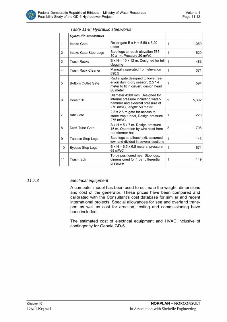
Federal Democratic Republic of Ethiopia – Ministry of Water Resources Volume 1 Feasibility Study of the GD-6 Hydropower Project Page 11-12
Chapter 10 NORPLAN – NORCONSULT Draft Report in Association with Shebelle Engineering
Table 11-8: Hydraulic steelworks Hydraulic steelworks
1 Intake Gate Roller gate B x H = 5.50 x 8.20 meter
1 1,059
2 Intake Gate Stop Logs Stop logs to reach elevation 585, 10 x 14, Pressure 20 mWC
1 529
3 Trash Racks B x H = 10 x 12 m. Designed for full clogging
1 483
4 Trash Rack Cleaner Manually operated from elevation 890.5
1 371
5 Bottom Outlet Gate Radial gate designed to lower res-ervoir during dry season, 2.5 * 4 meter to fit in culvert, design head 60 meter
1 594
6 Penstock Diameter 4200 mm. Designed for internal pressure including water-hammer and external pressure of 270 mWC, length: 50 meter
2 5,302
7 Adit Gate 2.5 x 2.5 m gate for access to stone trap tunnel, Design pressure 275 mWC
1 223
8 Draft Tube Gate B x H = 5 x 7 m. Design pressure 15 m. Operation by wire hoist from transformer hall
2 706
9 Tailrace Stop Logs Stop logs at tailrace exit, assumed low, and divided in several sections
1 143
10 Bypass Stop Logs B x H = 6.5 x 6.5 meters, pressure 69 mWC
1 571
11 Trash rack To be positioned near Stop logs, dimensioned for 1 bar differential pressure
1 149
11.7.3 Electrical equipment
A computer model has been used to estimate the weight, dimensions and cost of the generator. These prices have been compared and calibrated with the Consultant's cost database for similar and recent international projects. Special allowances for sea and overland trans-port as well as cost for erection, testing and commissioning have been included.
The estimated cost of electrical equipment and HVAC inclusive of contingency for Genale GD-6.

Federal Democratic Republic of Ethiopia – Ministry of Water Resources Volume 1 Feasibility Study of the GD-6 Hydropower Project Page 11-13
Chapter 10 NORPLAN – NORCONSULT Draft Report in Association with Shebelle Engineering
Table 11-9 Cost of Electrical equipment
Description Q'ty Amount Mill. USD
Generators Sn = 150 MVA PF = 0.96 n = 300 rpm
2 Unit 19.230
Main transformers Three-phase
Sn = 150 MVA Ug / 400 kV ek = 13 %
2 Unit 6.900
400 kV Cables PEX insulated L = 1100 m 1 Set 6.400
400 kV Switchgear Conventional Outdoor 1 L.S. 2.470
Transformer/cable connec-tion 400 kV SF6 1 L.S. 1.170
33 kV switchgear Cubicle mounted
Powerhouse and switchyard 1 L.S. 3.220
Station Supply equipment 400 V a.c. 220 V d.c. 1 L.S. 6.700
Control, protection & tele-com 3.730
Aux. cables & Earthing 3.640
Domestic installations 1.200 33 kV lines to Intake & Camp 1.100
Spare Parts 3.020
11.7.4 Small hydropower unit
A minimum water release flow of 2.5 m3/s is proposed from the Dam site. The available head at the Dam site is about 60 m, and it is pro-posed to install a small turbine to utilise the energy in the outlet. The cost of the complete small turbine unit is given in Table 11-10.
.

Federal Democratic Republic of Ethiopia – Ministry of Water Resources Volume 1 Feasibility Study of the GD-6 Hydropower Project Page 11-14
Chapter 10 NORPLAN – NORCONSULT Draft Report in Association with Shebelle Engineering
Table 11-10: Small turbine unit cost
Item Description Q'ty Unit Amount 1000 USD
Compensation water Turbine
1.3 MW horisontal Shaft Unit with contoller and butterfly valve
1 Each 557,000
Butterfly Shut Off Valve
Diameter 800 butterfly valve 1 Each 93,000
Auxilliary Equiment
Parallel bypass in case of power-plant failure.
1 L.S. 107,000
Crane 10 ton electrical hoist. 1 Each 9,000
SUM, MECHANICAL EQUIPMENT 766,000
Generator 1500 kVA, 1000 rpmBrushless exciter & AVR
1 Each 314,000
Transformer 1500 kVA, 33/3,3 kVOil insulated
1 Each 114,000
3,3 kV cable ter-mination
With circuit breaker 1 L.S. 95,000
3,3 kV cable PEX insulated 200 m 46,000
33 kV line termina-tion
Pole mounted 1 L.S. 15,000
Control & auxiliary equipment
1 L.S. 300,000
SUM, ELECTRICAL EQUIPMENT 884,000
SUM, MECHANICAL & ELECTRICAL EQUIPMENT 1 650,000
11.8 Transmission system
The cost for transmission system is calculated based on tendered prices received from a number of projects in Africa and adjusted ac-cording to the price level in Ethiopia. A summary of the costs for the transmission system are given in Table 11-11.
The distance to GD-3 is 80 km and to Negele substation about 70 km.
Table 11-11: Cost of Transmission System 400 kV Transmission line to GD-3 187 600 USD/m 33 kV double circuit Construction by local contractor
14 000 USD/m
11.9 Environmental cost estimate
The environmental costs provide for the compensation and mitigation of direct impacts not managed under the main design concept.

Federal Democratic Republic of Ethiopia – Ministry of Water Resources Volume 1 Feasibility Study of the GD-6 Hydropower Project Page 11-15
Chapter 10 NORPLAN – NORCONSULT Draft Report in Association with Shebelle Engineering
The guiding principle is that people or communities directly affected by the construction of the GD-6 HEPP should be no worse off (and preferably better off) after project implementation. What must be avoided is a situation whereby people in the direct impact zone “sub-sidise” the project through a reduction in their standard of living or in-come generation opportunities.
Table 11-12: Environmental cost
No. Item Cost and Units Capital cost Annual Recurrent Cost Construction
Phase 1 Reservoir clearing (costed as civil works) 800/ha 654,400 2 Technical environmental optimisation provisional 200,000 3 Compensation for cultivated land 6.000/ha 60,000 4 Outreach, awareness and capacity building 150.000 150,000 175,000 5 Rehabilation of works areas 9.000/ha 135,000 6 Monitoring of construction work 125.000/year 15,000 125,000 7 Post construction environmental audit 70.000 70,000
Sub-Totals 560,000 300,000
Contingency at 10% 56,000 30,000
Totals (USD) 616,000 330,000
Total for Construction Phase (assumed at 5 years) 2,266,000
11.10 Engineering, administration and physical contingencies
To arrive at the total cost for the project, the costs of engineering, su-pervision, Owners administration and contingencies have to be added to the construction costs.
Final design, preparation of bid documents, bid evaluation and par-ticipation in contract negotiations, preparation of work drawings and supervision of construction have been taken as 8% of the total con-struction cost and contingencies.
The owner’s administration costs have been taken as 3 % of the total costs.
To cover unforeseen costs, contingencies have been added to the construction costs with 5% for electrical and mechanical work, 10% for environmental mitigations, infrastructure works and transmission works and 10% for other civil works.

Federal Democratic Republic of Ethiopia – Ministry of Water Resources Volume 1 Feasibility Study of the GD-6 Hydropower Project Page 11-16
Chapter 10 NORPLAN – NORCONSULT Draft Report in Association with Shebelle Engineering
11.11 Summary of costs
Table 11-13: Cost summary - Genale GD-6 1000 USD 1000 USD 1000 USD Item no Item Total Cost Local Cost Foreign. Cost
1 INFRASTRUCTURE 1.1 ROADWORKS 13 408 10 520 2 8881.2 HOUSING 18 006 14 405 3 6011.3 OFFICES etc. 6 450 5 156 1 2941.4 GENERAL COST 18 % 6 815 5 414 1 4011.5 CONTINGENCIES 10 % 4 468 3 549 918
TOTAL INFRASTRUCTURE 49 147 39 044 10 1032 RESERVOIR
2.1 COMPENSATION 60 60 02.2 SITE CLEARING 660 594 662.3 GENERAL COST 18 % 130 118 122.4 CONTINGENCIES 10 % 85 77 8
TOTAL RESERVOIR 935 849 863 DAM
3.1 EXCAVATION DAM SITE 3 817 1 844 1 9733.2 DIVERSION 10 677 5 663 5 0143.3 COFFERDAMS 5 031 1 932 3 0993.4 DAM 46 582 17 260 29 3223.5 SPILLWAY 14 442 8 442 6 0003.6 GENERAL COST 25 % 19 183 8 324 10 8593.7 CONTINGENCIES 10 % 9 592 4 162 5 429
TOTAL DAM 109 325 47 627 61 6984 INTAKE
4.1 EXCAVATION 560 276 2844.2 CONCRETE WORKS 868 518 3494.3 STEEL STRUCTURES 2 524 529 1 9964.4 GENERAL COST 25 % 988 331 6574.5 CONTINGENCIES 10 % 494 165 329
TOTAL INTAKE 5 434 1 819 3 6155 WATERWAY
5.1 HEADRACE TUNNEL 21 247 4 671 16 5755.2 SURGE CHAMBER HEADRACE 6 839 2 759 4 0805.3 PENSTOCK TUNNELS 6 041 1 059 4 9825.4 DRAFT TUBES 1 414 447 9675.5 SURGE CHAMBER TAILRACE 6 887 2 346 4 5425.6 TAILRACE TUNNEL 52 880 11 281 41 5995.7 TAILRACE OUTLET 1 768 892 8765.8 GENERAL COST 25 % 17 248 4 006 13 2425.9 CONTINGENCIES 10 % 8 624 2 003 6 621
TOTAL WATERWAY 122 947 29 464 93 4836 POWER STATION
6.1 MAIN ACCESS TUNNEL 4 638 1 661 2 9766.2 ADITS TUNNELS 5 594 1 976 3 618
6.3 POWER STATION AND TRANSFORMER CAVERN 1 698 589 1 108
6.4 CONCRETE WORKS 3 726 2 305 1 4226.5 PORTAL 432 243 1896.6 CABLE TUNNEL and CULVERT 1 466 591 8756.7 GENERAL COST 25 % 1 830 932 8986.8 CONTINGENCIES 10 % 915 466 449
TOTAL POWER STATION 20 299 8 763 11 5357 POWER STATION EQUIPMENT
7.1 MECHANICAL 27 132 5 426 21 7067.2 ELECTRICAL 48 000 3 389 44 6117.3 HVAC 1 284 257 1 0287.4 GENERAL COST 10 % 7 642 907 6 7347.5 CONTINGENCIES 5 % 4 203 499 3 704

Federal Democratic Republic of Ethiopia – Ministry of Water Resources Volume 1 Feasibility Study of the GD-6 Hydropower Project Page 11-17
Chapter 10 NORPLAN – NORCONSULT Draft Report in Association with Shebelle Engineering
TOTAL POWER STATION EQUIPMENT 88 261 10 479 77 7828 SMALL HYDROPOWER PLANT
8.1 CIVIL WORKS 245 71 1748.2 EL&MECH 1 660 132 1 5288.3 GENERAL COST 10 % 190 20 1708.4 CONTINGENCIES 5 % 105 11 94
TOTAL SMALL HYDROPOWER PLANT 2 200 234 1 965
9 TRANSMISSION, SWITCHYARD, LOCAL SUPPLY
9.1 SWITCHYARD 3 491 1 252 2 2399.2 400 kV TRANSMISSIOON LINES 16 069 4 897 11 1729.3 POWER SUPPLY 2 410 964 1 4469.4 GENERAL COST 15 % 3 296 1 067 2 2299.5 CONTINGENCIES 5 % 1 263 409 854
TOTAL TRANSMISSION, SWITCHYARD, LOCAL SUPPLY 26 530 8 589 17 940
10 ENVIRONMENTAL COST 2 200 1 980 220
11 ENGINEERING,SUPERVISION AND AD-MINISTRATION 10 % 42 508 14 861 27 646
TOTAL PROJECT COST 469 780 163 710 306 070

Federal Democratic Republic of Ethiopia – Ministry of Water Resources Volume 1 Feasibility Study of the GD-6 Hydropower Project Page 12-1
Chapter 10 NORPLAN – NORCONSULT Draft Report in Association with Shebelle Engineering
12 CONSTRUCTION PLANNING
12.1 Introduction
The construction schedule described in this chapter shows that the Genale GD-6 can be commissioned after about 5 years of construc-tion work, following a preparatory period of about 2 years for prepara-tion of design, bidding documents and concluding the contract nego-tiations. The following conditions prevail:
• Mobilisation for tunnelling works and road construction should start in the month of October.
• The existing track to the Genale River will immediately be up-graded to allow mobilisation for tunnel excavation of the main ac-cess tunnel.
• Mobilisation of TBM (tunnel boring machine) at site shall be in month 16.
• Supply of electric power is available at the sites ahead of start of main construction works.
More details are given below regarding construction techniques and approach.
12.2 Construction areas
12.2.1 Construction camps
The main construction camp will be located near the Genale River, on the hill, next to the switchyard area and main access tunnel.
Satellite camps will mainly be at the Dam site, at the intake site and borrow area near the intake. A small camp will also be required at the tailrace for a short period.
12.2.2 Residence facilities
In the initial phase (1 year) temporary housing will be established at the main construction camp, while the construction of the permanent camp is going on. The permanent camp will be used for the Owners and Contractors personnel for the rest of the construction period.
The owner's permanent camp is proposed located on the south side of the river, on a plateau some 2 km upstream of the main construc-tions camp.
For labour accommodation, it is assumed that the contractor will ar-range a separate camp in accordance with the government regula-tions.
Temporary water supply to the camp areas will be supplied from the river. Water treatment plants and wastewater treatment plants will be provided at the sites.
Federal Democratic Republic of Ethiopia – Ministry of Water Resources Volume 1 Feasibility Study of the GD-6 Hydropower Project Page 12-2
Chapter 10 NORPLAN – NORCONSULT Draft Report in Association with Shebelle Engineering
12.2.3 Power supply
Power supply during construction will be through a new double circuit 33 kV power line to be constructed from the Negele substation. The line should preferably be ready for use as soon as tunnel excavations works start in month 2, but temporary power supply be diesel genera-tors must be expected.
12.2.4 Spoil deposits
Excavation of the dam foundation, intake cut, the tunnels and the powerhouse will result in large quantities of material (approx. 2 mill m3).
Rock spoils from drilling of tunnel and from powerhouse excavation will be processed and used as concrete aggregates and as fill mate-rials for the GD-6 dam.
All spoil from the Power station area is expected to be transported to the dam site.
If part of the tunnel excavation will be done from the tailrace outlet, suitable spoil deposit area is identified in the Kebeya valley.
12.2.5 Borrow area
A borrow area for the purpose of excavating materials for the dam construction, is located on the right side of the river, next to the exca-vated cut for the intake.
12.2.6 Concrete aggregate production plant
The GD-6 construction areas are located within at distance of 7 km upstream (intake) and 17 km downstream (tailrace outlet) of the pow-erhouse area and main construction camp. It is expected that one aggregate production plants, which will comprise plants for crushing, screening, sand milling and washing will be located in the main con-struction camp.
The tunnels and the caverns are all located in basement rock and the quality is considered to be good enough for crushing to concrete ag-gregates.
A few possible borrow sites for sandy material are located, but they may not be suitable for concrete production, due to long hauling dis-tance and limited quantity.
12.2.7 Concrete batching and mixing plants
One concrete batching and mixing plants are foreseen to be located at the main camp.
The concrete mixing plant will provide the concrete for the dams and spillways, the power intakes and the powerhouses and for rock sup-port in the tunnels.

Federal Democratic Republic of Ethiopia – Ministry of Water Resources Volume 1 Feasibility Study of the GD-6 Hydropower Project Page 12-3
Chapter 10 NORPLAN – NORCONSULT Draft Report in Association with Shebelle Engineering
Shotcrete for tunnel support works and conventional concrete (CVC) for the tunnel portal structures will be required from the start of the construction works. The batching and mixing plants with cement stor-age silos and aggregate silos therefore have to be erected at the start of the construction works.
The concrete plant should have sufficient capacity to provide the necessary shotcrete for rock support works and for supply of concrete to the dams, to the powerhouse and to the waterway tunnel linings etc. The plant should have an expected capacity of 80-100 m3/h.
The largest concrete works to be executed is the powerhouse area with about 20 000 m3, and the dam/spillway works with some 40 000 m3.
12.2.8 Storage of fuel and explosives
Safe transport and storage constitute an important logistics and secu-rity challenge. The question of supply and storage of explosives will have to be taken up with the potential suppliers and the relevant au-thorities in the final/tender design phase.
12.3 Project construction GD-6
The drilling of 16 km waterway of GD-6 by one tunnel boring machine (TBM) Ø=9.0 m, is expected to last 170 weeks plus required time for demobilising the TBM at the intake and mobilise it in the tailrace surge chamber (totally about 4 years).
It will be of great importance to mobilise and start drilling of the wa-terway as soon as possible. It is therefore planned to use the existing track down to Genale to start mobilising for the D&B tunnel excava-tion by the powerhouse, for immediate start of the Main Access tun-nel.
12.3.1 Main Access Tunnel
Mobilisation for tunnel excavation is expected to start 6 weeks after road construction starts.
Excavation of the access tunnel and the adit to the headrace should be start immediately after mobilisation at the main camp. The time required for excavation of the 1 300 m long access and adit tunnels are 33 weeks, and 5 weeks for excavation of the penstock chamber.
The mobilisation of TBM should be within 16 months from signing of the construction contract. Ordering of the TBM is expected to take place immediately after signing, and 16 months would be the ex-pected time required for manufacturing and transporting a TBM to Ethiopia.
12.3.2 Diversion works
Construction of the road from the main camp to the Dam site is ex-pected to take 25 weeks.

Federal Democratic Republic of Ethiopia – Ministry of Water Resources Volume 1 Feasibility Study of the GD-6 Hydropower Project Page 12-4
Chapter 10 NORPLAN – NORCONSULT Draft Report in Association with Shebelle Engineering
After mobilisation of camps/workshops and construction of internal roads, excavation for the diversion culverts and the spillway with chute canal, is started. Some of the excavated material will be used to establish the Phase 1 cofferdam around the area of the 3 concrete diversion culverts of 44 m2 each.
The diversion culverts will be located at the right river bank, and an area of about 30 m width and 250 m length shall be excavated and prepared for construction of the 3 culverts. The required cofferdam will have an overall length of 350 m along the right side of the river, but will be relatively low, around 5-6 m.
The completion of the diversion works is expected to be after 45 weeks.
12.3.3 Construction of asphaltic concrete core dam
Succeeding the construction of the diversion culverts construction of the Phase 2 cofferdams could start. With the construction of the up-stream cofferdam to el. 538, crossing of the river is easy, and clear-ing, grubbing and excavation of soft material in the upper parts of the left dam abutment can also start.
When the construction of the downstream cofferdam is also com-pleted to el. 528, excavation of the dam foundation in the river bed can start.
After completing the excavation, the foundation preparation works are done. The preparation work comprise minor blasting, blanket grout-ing, concreting of the foundation plinth for the asphaltic concrete core, and curtain grouting underneath the plinth.
When the foundation preparations are completed in the lower part of the dam, the embankment placing is started. The embankment com-prises zones of quarried rock fill, drainage layer, transition layers from tunnel spoil and a filter of crushed rock between the transition layer and the core. The different zones are placed and compacted as specified in the description of the dam. The embankment fill is as-sumed placed at an average rate of 70 000 m3/week, and is esti-mated to be completed in 45 weeks.
The plugs and the gate in the diversion culverts/bottom outlet are in-stalled during a low flow period February-March after completion of the dam and the spillway.
12.3.4 Construction of spillway
Construction of the spillway can be started as soon as mobilisation at the Dam site is completed. Excavation of more than 200 000 m3 is expected. The rock masses should preferably be taken directly into the dam embankment. The concrete works will start in the side channel, weir and chute.

Federal Democratic Republic of Ethiopia – Ministry of Water Resources Volume 1 Feasibility Study of the GD-6 Hydropower Project Page 12-5
Chapter 10 NORPLAN – NORCONSULT Draft Report in Association with Shebelle Engineering
12.3.5 Construction of intake
The intake is located some 900 m south of the dam. An intake cut must be excavated to el. 365 before concrete construction works can start. Major rock excavation works is planned at the site, as the ex-cavated material will be used for fill material of the dam.
After the TBM has completed the headrace, are demobilised and moved to the tailrace, the intake channel will be lowered by min. 5 m to create a volume for settlement of sediments in front of the intake.
The borrow area for dam material is shown on the drawing just in front of the intake channel.
12.3.6 Construction of tailrace outlet
The tailrace outlet is designed with an outlet construction including stop logs and a tailrace channel of 200 m length back to the Genale River.
The main objective of the design additional to safe closing of the out-let, is that the TBM shall be demobilised in the open after completing the tailrace tunnel. This requires a bay of some 50 m length, which is located between the rock cut and the stop log structure.
Construction of the tailrace structures will be after the major concrete works are completed.
12.3.7 Construction of tunnels
Waterway
Tunnel construction will be done by the TBM method, and the follow-ing construction equipment will be required:
• One single gripper TBM, Ø=9m, with ordinary back-up rig. The TBM is electrically driven, requiring 3.5 MW capacity, and has the following standard back-up equipment:
• Roof bolting equipment
• Probe drilling equipment
• Ring beam manipulator
• Shotcrete manipulator
• Back-up belt conveyor
The headrace tunnel, 4.7 km, will be excavated from the Power sta-tion and upstream to the intake. The high pressure tunnel, 800 m, has a slope of 1:10 while the remaining upstream will have a slope 1:29. Drainage of the tunnel will then be easy by gravity, down to the Power station, where pumping will be required.
After completion of the headrace the TBM will be shifted to the tail-race surge chamber where it will be mobilised to drill the 11.3 km long tailrace tunnel. The tunnel is almost horizontal, starting at el. 338.5 and ending at el. 340.
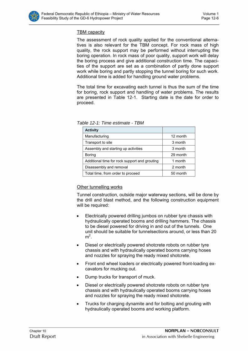
Federal Democratic Republic of Ethiopia – Ministry of Water Resources Volume 1 Feasibility Study of the GD-6 Hydropower Project Page 12-6
Chapter 10 NORPLAN – NORCONSULT Draft Report in Association with Shebelle Engineering
TBM capacity
The assessment of rock quality applied for the conventional alterna-tives is also relevant for the TBM concept. For rock mass of high quality, the rock support may be performed without interrupting the boring operation. In rock mass of poor quality, support work will delay the boring process and give additional construction time. The capaci-ties of the support are set as a combination of partly done support work while boring and partly stopping the tunnel boring for such work. Additional time is added for handling ground water problems.
The total time for excavating each tunnel is thus the sum of the time for boring, rock support and handling of water problems. The results are presented in Table 12-1. Starting date is the date for order to proceed.
Table 12-1: Time estimate - TBM Activity
Manufacturing 12 month Transport to site 3 month Assembly and starting up activities 3 month Boring 29 month Additional time for rock support and grouting 1 month Disassembly and removal 2 month Total time, from order to proceed 50 month
Other tunnelling works
Tunnel construction, outside major waterway sections, will be done by the drill and blast method, and the following construction equipment will be required:
• Electrically powered drilling jumbos on rubber tyre chassis with hydraulically operated booms and drilling hammers. The chassis to be diesel powered for driving in and out of the tunnels. One unit should be suitable for tunnelsections around, or less than 20 m2.
• Diesel or electrically powered shotcrete robots on rubber tyre chassis and with hydraulically operated booms carrying hoses and nozzles for spraying the ready mixed shotcrete.
• Front end wheel loaders or electrically powered front-loading ex-cavators for mucking out.
• Dump trucks for transport of muck.
• Diesel or electrically powered shotcrete robots on rubber tyre chassis and with hydraulically operated booms carrying hoses and nozzles for spraying the ready mixed shotcrete.
• Trucks for charging dynamite and for bolting and grouting with hydraulically operated booms and working platform.

Federal Democratic Republic of Ethiopia – Ministry of Water Resources Volume 1 Feasibility Study of the GD-6 Hydropower Project Page 12-7
Chapter 10 NORPLAN – NORCONSULT Draft Report in Association with Shebelle Engineering
• Mobile, electrically powered ventilation fan units, service contain-ers and miscellaneous accessories.
• Backhoe-mounted hydraulic hammers for scaling.
• Hydraulically operated articulated forms for concreting of roof and walls in the tunnels. The form to be mounted on rubber tyres for convenient transport.
The sequences of excavation are drilling, charging, blasting, ventilat-ing, loading and mucking out. After each round temporary rock sup-port will be applied as required. Normally this will be by rock bolting and shotcrete. When adverse conditions are met, thick shotcrete lay-ers combined with reinforced shotcrete ribs might be required.
The headrace surge tunnel is assumed excavated descending from outside, el. 605, towards the vertical shaft to the headrace tunnel. The shaft will be, 120 m long, and excavated by first drilling a, i.e., dia. 2 m shaft. Enlargement to 50 m2 will be by drilling and blasting from above, using the pilot shaft as chute for the spoil.
After the excavation of the main access tunnel, followed by excava-tion of the headrace adit is completed, the the top headings of the powerhouse and the transformer hall, the adit to the tailrace surge tunnel and the draft tube tunnels will be started. After these tunnels are excavated the tailrace surge chamber and tailrace tunnel is ready for excavation.
Excavation of the cable tunnel will be done from the transformer hall to the switchyard. The upper part of the tunnel will be a drilled shaft, dia. 4m, about 80 m long.
12.3.8 Construction of the powerhouse and the transformer cavern
Excavation works
The upper 6-7 m high top heading of the powerhouse cavern will be excavated from the access through the transformer gallery.
The permanent rock support of the cavern roof consisting of ~0.10 m fibre reinforced shotcrete and grouted rock bolts will be installed be-fore further excavation of the powerhouse cavern.
Excavation from the top heading down to the machine hall floor will take place by benching and the access tunnel will be used for trans-portation of the excavated rock masses.
After further benching down to the generator floor level, the bus-bar tunnels to the transformer cavern will be excavated. The bottom part of the cavern below the generator floor will be excavated partly from above through the main access tunnel and partly from the tailrace tunnel/draft tubes.
Permanent rock support to the walls, mainly by systematic rock bolt-ing and layers of shotcrete will be performed as an integrated part of the excavation activities. This will allow for safe, working conditions immediately after excavation of the cavern has been completed.

Federal Democratic Republic of Ethiopia – Ministry of Water Resources Volume 1 Feasibility Study of the GD-6 Hydropower Project Page 12-8
Chapter 10 NORPLAN – NORCONSULT Draft Report in Association with Shebelle Engineering
Concrete works in the powerhouse
After excavation of the upper part of the cavern above machine hall floor level, concrete works for the overhead crane beams will follow. The crane beams and parts of the supporting columns are fixed to the walls by grouted rock anchors. The permanent support of the crane beams will be established after excavation is completed by extension of the columns down into the powerhouse sub-structure.
After excavation of the powerhouse cavern the concrete works for the 15 m long off-loading and erection bay in the outer end of the power-house is started, and completed as fast as possible. As soon as this section of the powerhouse has reached the machine hall floor level, the overhead travelling crane is installed. Thereafter the draft tube steel linings are erected and embedded, followed by erection and embedding of penstock steel linings and turbine spiral-casings. Fi-nally the concrete works on the generator floor and the machine hall floor is done.
Installation and erection of electro-mechanical equipment
Prior to installation and erection of any permanent mechanical and electrical equipment, except for the travelling crane, all major civil works in the powerhouse has to be completed in order to reduce the extent of spoil, dust etc. in the installation period. This will include a thorough cleaning up of the machine hall cavern.
No separate erection bay has been constructed in the powerhouse. It is therefore assumed that erection of Unit 2 is started when erection of Unit 1 is almost completed.
Erection and installation of auxiliary electrical and mechanical equip-ment will be done in parallel with the installation of the generating units after completion of the civil works in the powerhouse and the transformer hall.
12.4 Implementation schedules GENALE GD-6
Drawing F01.
Implementation schedules based upon dependent activities has been prepared for the Genale GD-6.
12.4.1 Construction times for tunnels
The construction time for each tunnel has been estimated based upon basic excavation rates for tunnelling and equivalent time rates for applying rock-support works such as shotcrete, rock bolts and concrete lining.
The basic tunnel excavation capacity in favourable rock masses, is estimated to 24 m3/hour for a D7 m tunnel.
For calculating advance rates, the following time consumption has been assumed for tunnel rock support works:

Federal Democratic Republic of Ethiopia – Ministry of Water Resources Volume 1 Feasibility Study of the GD-6 Hydropower Project Page 12-9
Chapter 10 NORPLAN – NORCONSULT Draft Report in Association with Shebelle Engineering
Excavation of D7 m tunnel in sound rock:
• Rock bolting in tunnels: 8 bolts/hour
• Fibre reinforced shotcrete: 6 m3/hour
• Rigging for rock bolting: 0.2 m/hour
• Rigging for shotcrete: 0.5 hour
The TBM will normally have a capacity of up to and above 90-100 m/week under conditions expected to be found at GD-6.
The average progress rate has been estimated to 35 - 40 m/week for tunnels where the whole cross section is excavated in one operation. Based upon the above assumptions the following average construc-tion rates have been applied (from Table 12-1):
• Headrace and tailrace tunnel: 95-100 m/week
• Access tunnel and other tunnels: 35-40 m/week
• Shafts: 12 m /week
The construction time for the waterway is expected to be 175 weeks, plus 12 weeks for remobilisation, and is expected to be on the critical path for commissioning of the first unit.
12.4.2 Genale GD-6 Underground powerhouse
Excavation of rock and providing shotcrete and grouted rock bolts and concreting of the crane girders is estimated to 24 weeks.
Installation of the draft tubes and the spiral casing and concreting of 5 100 m3 of concrete is estimated to require 70 weeks. The main elec-tro-mechanical installations can commence 70 weeks after start of the installation of the draft tubes.
Construction of the access tunnel, the powerhouse and installation of the electromechanical equipment and filling of the reservoir is on the critical path. It is estimated that testing of unit 1 may start 220 weeks after start of construction.
12.4.3 Implementation schedule Genale GD-6
With the assumptions given above regarding excavation rates, pow-erhouse concrete works rates, time for erection of the generating units, construction rate for the dam and the filling rate of the reservoir the commissioning time for the power plant has been estimated based upon dependency between the different activities.
The critical path for commissioning of the Genale GD-6 power plant appears to be construction of the waterway, if drilled by one TBM only. All generating units will be installed and waiting for the reservoir to be filled up to MOL .

Federal Democratic Republic of Ethiopia – Ministry of Water Resources Volume 1 Feasibility Study of Genale GD6 Hydropower Project Page 13-1
GD-6 Feaisbility Report Final Volume 1.doc NORPLAN – NORCONSULT JV in Association with Shebelle Engineering
13 ECONOMIC AND FINANCIAL ANALYSIS
13.1 Power Markets and Supply Alternatives
13.1.1 Market Overview
The optimal generating characteristics and the timing of the construc-tion of the GD-6 will depend on the markets into which its electricity will be sold. Given the location of the project relative to the largest concentrations of consumers in the region, the two most obvious po-tential markets, as is the case for the recently studied Genale-3 (GD-3) scheme, are the Addis Ababa area via the Ethiopian Intercon-nected System (ICS) and the Kenyan national grid via a link to a pro-posed new HV transmission line.4
In reality, the future markets for Ethiopian electricity in general are likely to expand far beyond the borders of Ethiopia, into the Sudan, westwards to Uganda and northwards to Egypt. The financing of a transmission interconnection with the Sudanese grid was approved in December 2007 and there are firm plans to create a cross-border trading grid within the Nile Basin countries. These developments will greatly increase the export market for competitively priced electrical energy and Ethiopia is ideally placed to exploit vast new markets.
With regard to the local market in Ethiopia, the main consumer centre is Addis Ababa located some 430 air-km (and 750 road-km) from the GD-6 project. This market could be supplied by reinforcing the exist-ing 230 kV network or through the planned 400 kV network. The closest node in the 230 kV interconnected grid is at the Melka Wakena HPP some 200 air-km from GD-6. However, the generation from the GD-6 project will be connected to the substation at the pro-posed GD-3 project, about 80 km upstream of the Genale River.
As for the Kenyan market, Kenya Electricity Generating Company Ltd. (KenGen), Kenya Power & Lighting Company Ltd.( KPLC), and EEPCo agreed in March 2006 on a concept of interconnecting the two power systems. A Memorandum of Understanding was signed in Nairobi in May 2006, and a study has recently (February 2009) been finalised to feasibility level paving the way for the financing of the pro-ject. The study, Ethiopia-Kenya Power Systems Interconnection Pro-ject, a co-operation between EEPCo and Kenyan Ministry of Energy (MOE), has been carried out by the German consulting company Fichtner Gmbh, and it will hereafter be referred to as the Interconnec-tion Study.
4 A third potential market is certain regions in Somalia. However, in the present assessment of poten-tial markets, Somalia has not been considered as it is currently very small (with a potential reportedly of 50 to 100MW and, particularly, the political environment is very unstable. However, this may well change at some time in the future.
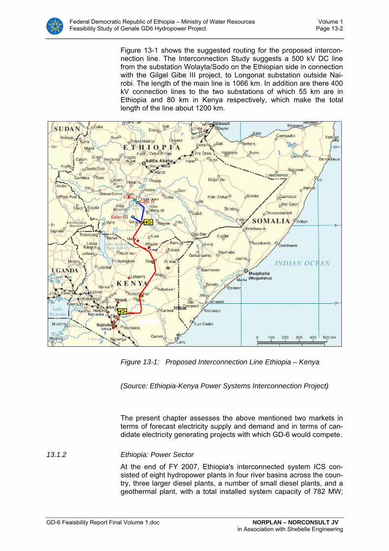
Federal Democratic Republic of Ethiopia – Ministry of Water Resources Volume 1 Feasibility Study of Genale GD6 Hydropower Project Page 13-2
GD-6 Feaisbility Report Final Volume 1.doc NORPLAN – NORCONSULT JV in Association with Shebelle Engineering
Figure 13-1 shows the suggested routing for the proposed intercon-nection line. The Interconnection Study suggests a 500 kV DC line from the substation Wolayta/Sodo on the Ethiopian side in connection with the Gilgel Gibe III project, to Longonat substation outside Nai-robi. The length of the main line is 1066 km. In addition are there 400 kV connection lines to the two substations of which 55 km are in Ethiopia and 80 km in Kenya respectively, which make the total length of the line about 1200 km.
Figure 13-1: Proposed Interconnection Line Ethiopia – Kenya
(Source: Ethiopia-Kenya Power Systems Interconnection Project)
The present chapter assesses the above mentioned two markets in terms of forecast electricity supply and demand and in terms of can-didate electricity generating projects with which GD-6 would compete.
13.1.2 Ethiopia: Power Sector
At the end of FY 2007, Ethiopia's interconnected system ICS con-sisted of eight hydropower plants in four river basins across the coun-try, three larger diesel plants, a number of small diesel plants, and a geothermal plant, with a total installed system capacity of 782 MW;

Federal Democratic Republic of Ethiopia – Ministry of Water Resources Volume 1 Feasibility Study of Genale GD6 Hydropower Project Page 13-3
GD-6 Feaisbility Report Final Volume 1.doc NORPLAN – NORCONSULT JV in Association with Shebelle Engineering
whereas dependable capacity is estimated at 758 MW. The average energy output of the ICS plants is 3,316 GWh
Small hydro and diesel power plants in the SCS have a combined ca-pacity of 32 MW.
Table 13-1: Existing Generation Capacity at End of FY 2007 Plant Name Hydro Diesel Geo-
thermal Total Total Average
Energy Year of Com-miss.
Installed Capacity (MW) Depend-able Cap. (MW)
(GWh)
Koka 43.2 - - 43.2 38 110 1960
Awash II 32.0 - - 32.0 32 165 1966
Awash III 32.0 - - 32.0 32 165 1971
Finchaa 134.0 - - 134.0 128 640 1973/200
Melka Wakena 153.0 - - 153.0 153 543 1988
Tis Abay I 11.4 - - 11.4 11 85 1964
Tis Abay II 73.0 - - 73.0 68 282 2001
Gilgel Gibe 184.0 - - 184.0 184 847 2004
Aluto Langano - - 7.3 7.3 0 0 1999
Awash 7 Kilo - 35.0 - 35.0 35
478
2004
Kaliti - 14.0 - 14.0 14 2004
Dire Dawa - 38.0 - 38.0 38 2004
Small Diesel - 25.2 - 25.2 25 - 1958/200
Total ICS 662.6 112.2 7.3 782.1 758 3316
Total SCS 6.2 25.6 - 31.7 31 - 1967/200
Source: EEPCo, Facts in Brief 2006

Federal Democratic Republic of Ethiopia – Ministry of Water Resources Volume 1 Feasibility Study of Genale GD6 Hydropower Project Page 13-4
GD-6 Feaisbility Report Final Volume 1.doc NORPLAN – NORCONSULT JV in Association with Shebelle Engineering
Energy production by system and source for the years FY 2002-2006 is shown in . The figures confirm the dominance of the ICS and hy-dropower.
Table 13-2: Energy Production by System and Source (GWh) System /Source / FY 2002 2003 2004 2005 2006
ICS
Hydro 1975.2 2007.1 2262.5 2521.0 2832.0
Diesel 0.1 21.1 15.8 18.4 12.0
Geothermal 1.0 0.0 0.0 0.0 0.0
Total 1976.3 2028.2 2278.3 2539.6 2844.0
SCS5
Hydro 16.6 16.5 16.6 17.9 19.0
Diesel 16.5 19.0 21.5 31.1 32.0
Total 33.1 35.5 38.1 49.0 51.0
ICS + SCS
Hydro 1991.8 2023.6 2297.1 2539.1 2851.0
Diesel 16.6 40.1 37.3 49.5 44.0
Geothermal 1.0 0.0 0.0 0.0 0.0
Total 2009.4 2063.7 2316.4 2588.6 2895.0
Source: EEPCo, Facts in Brief 2006
The ICS faced supply deficits in the past, which led to power ration-ing. In order to alleviate this problem, EEPCo introduced 87 MW of diesel fired power plants in 2004 in selected parts of the grid (in addi-tion commissioning the Gilgel Gibe hydroelectric project). For a few years thereafter, Ethiopia has been in a comfortable position as far as its supply and demand balance is concerned. However, with rapid growth, particularly in generation requirements in the last couple of years, the energy balance is now being strained, as shown in Table 13-3. To cope with this situation, and also acknowledging the vagaries of rainfall and the fact that demand is increasing significantly, GoE is developing an ambitious generation and transmission program, in ad-
5 Some discrepancies are noted for the SCS in relation to figures in Table 2.1.
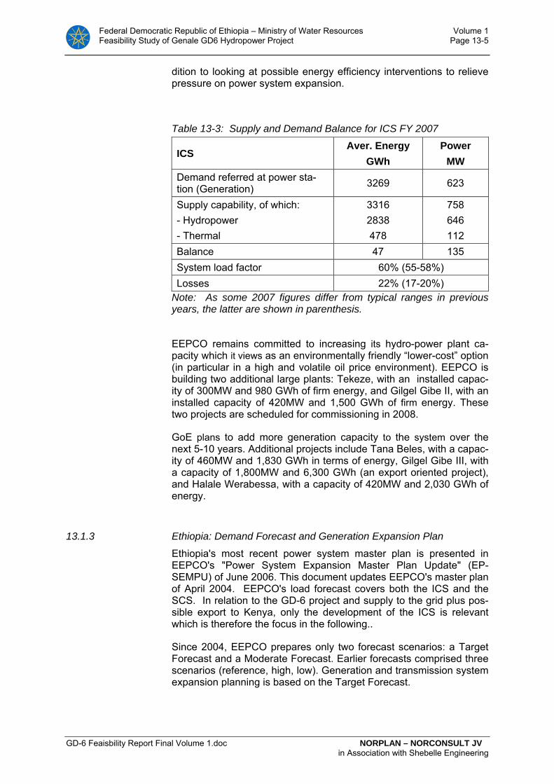
Federal Democratic Republic of Ethiopia – Ministry of Water Resources Volume 1 Feasibility Study of Genale GD6 Hydropower Project Page 13-5
GD-6 Feaisbility Report Final Volume 1.doc NORPLAN – NORCONSULT JV in Association with Shebelle Engineering
dition to looking at possible energy efficiency interventions to relieve pressure on power system expansion.
Table 13-3: Supply and Demand Balance for ICS FY 2007
ICS Aver. Energy
GWh Power
MW Demand referred at power sta-tion (Generation) 3269 623
Supply capability, of which: - Hydropower - Thermal
3316 2838 478
758 646 112
Balance 47 135 System load factor 60% (55-58%) Losses 22% (17-20%)
Note: As some 2007 figures differ from typical ranges in previous years, the latter are shown in parenthesis.
EEPCO remains committed to increasing its hydro-power plant ca-
pacity which it views as an environmentally friendly “lower-cost” option (in particular in a high and volatile oil price environment). EEPCO is building two additional large plants: Tekeze, with an installed capac-ity of 300MW and 980 GWh of firm energy, and Gilgel Gibe II, with an installed capacity of 420MW and 1,500 GWh of firm energy. These two projects are scheduled for commissioning in 2008.
GoE plans to add more generation capacity to the system over the next 5-10 years. Additional projects include Tana Beles, with a capac-ity of 460MW and 1,830 GWh in terms of energy, Gilgel Gibe III, with a capacity of 1,800MW and 6,300 GWh (an export oriented project), and Halale Werabessa, with a capacity of 420MW and 2,030 GWh of energy.
13.1.3 Ethiopia: Demand Forecast and Generation Expansion Plan
Ethiopia's most recent power system master plan is presented in EEPCO's "Power System Expansion Master Plan Update" (EP-SEMPU) of June 2006. This document updates EEPCO's master plan of April 2004. EEPCO's load forecast covers both the ICS and the SCS. In relation to the GD-6 project and supply to the grid plus pos-sible export to Kenya, only the development of the ICS is relevant which is therefore the focus in the following..
Since 2004, EEPCO prepares only two forecast scenarios: a Target Forecast and a Moderate Forecast. Earlier forecasts comprised three scenarios (reference, high, low). Generation and transmission system expansion planning is based on the Target Forecast.
Federal Democratic Republic of Ethiopia – Ministry of Water Resources Volume 1 Feasibility Study of Genale GD6 Hydropower Project Page 13-6
GD-6 Feaisbility Report Final Volume 1.doc NORPLAN – NORCONSULT JV in Association with Shebelle Engineering
The Target Load Forecast assumes an economic growth of 12% and 150,000 new connections annually over the entire planning horizon, reflecting the Government's commitment to economic development and poverty eradication. The Target Forecast results in net genera-tion requirements of 71,570 GWh and a peak demand of 14,330 MW in FY 2030, yielding an average annual demand growth rate of 14.3%. The Moderate Forecast for FY 2030 is about 50% lower (34,030 GWh and 6,814 MW, giving an average growth rate of 10.9%). Both forecasts, shown in Table 13-4 are considerably higher than EEPCo’s forecasts in 20046.
EEPCo’s generation expansion plan, based on the Target Forecast is shown in Table 13-4 The expansion plan for the Moderate Demand Scenario (only prepared up to 2016) is similar to that for the Target Scenario except for a delay of Halele Werabesa HEPP until 2016.
The plan involves massive capacity additions, increasing the capacity of 726 MW in 2006 to 4,476 MW of dependable capacity in the ICS in 2015, and 14,823 MW in 2030.
The capacity additions are, with the exception of the initial years, suf-ficient to meet the national peak demand including reserve require-ments. After the commissioning of Gilgel Gibe III HEPP, the reserve margin exceeds 50%. There is considerable surplus capacity not only for the assumed export to Sudan (200 MW) and Djibouti (100 MW), but also for further power exports. However, this surplus decreases drastically after 2023, so that it cannot be used for firm exports. Since the preparation of the Master Plan Update in 2006, it is understood that some changes have been made to mid-term planning.
In EEPCO’s plan, projects in the Genale Dawa basin with a total ca-pacity of 605MW will be added in 2018 which, according to EEPCO, includes GD-6. However, in the Feasibility Study Update (2006) for the Ethiopia-Sudan Power Systems Interconnection Project, GD-3 is scheduled for 2015 and GD-6 for 2024.
6 EEPCo’s 2004 forecast showed an average growth rate of 9.1% p.a. for the Moderate Forecast, and 9.7% p.a. for the Target Forecast.
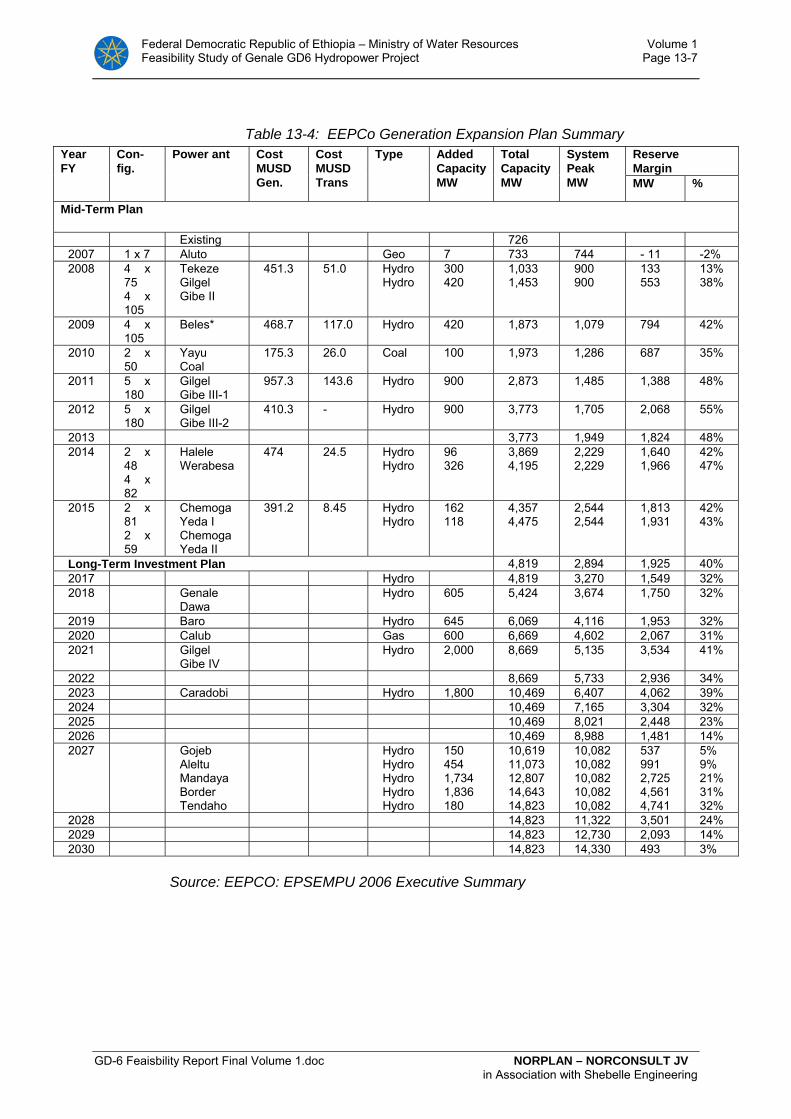
Federal Democratic Republic of Ethiopia – Ministry of Water Resources Volume 1 Feasibility Study of Genale GD6 Hydropower Project Page 13-7
GD-6 Feaisbility Report Final Volume 1.doc NORPLAN – NORCONSULT JV in Association with Shebelle Engineering
Table 13-4: EEPCo Generation Expansion Plan Summary Year FY
Con-fig.
Power ant Cost MUSD Gen.
Cost MUSD Trans
Type Added Capacity MW
Total Capacity MW
System Peak MW
Reserve Margin MW %
Mid-Term Plan
Existing 726 2007 1 x 7 Aluto Geo 7 733 744 - 11 -2% 2008 4 x
75 4 x 10⁵
Tekeze Gilgel Gibe II
451.3 51.0 Hydro Hydro
300 420
1,033 1,453
900 900
133 553
13% 38%
2009 4 x 10⁵
Beles* 468.7 117.0 Hydro 420 1,873 1,079 794 42%
2010 2 x 50
Yayu Coal
175.3 26.0 Coal 100 1,973 1,286 687 35%
2011 5 x 180
Gilgel Gibe III-1
957.3 143.6 Hydro 900 2,873 1,485 1,388 48%
2012 5 x 180
Gilgel Gibe III-2
410.3 - Hydro 900 3,773 1,705 2,068 55%
2013 3,773 1,949 1,824 48% 2014 2 x
48 4 x 82
Halele Werabesa
474 24.5 Hydro Hydro
96 326
3,869 4,195
2,229 2,229
1,640 1,966
42% 47%
2015 2 x 81 2 x 59
Chemoga Yeda I Chemoga Yeda II
391.2 8.45 Hydro Hydro
162 118
4,357 4,475
2,544 2,544
1,813 1,931
42% 43%
Long-Term Investment Plan 4,819 2,894 1,925 40% 2017 Hydro 4,819 3,270 1,549 32% 2018 Genale
Dawa Hydro 605 5,424 3,674 1,750 32%
2019 Baro Hydro 645 6,069 4,116 1,953 32% 2020 Calub Gas 600 6,669 4,602 2,067 31% 2021 Gilgel
Gibe IV Hydro 2,000 8,669 5,135 3,534 41%
2022 8,669 5,733 2,936 34% 2023 Caradobi Hydro 1,800 10,469 6,407 4,062 39% 2024 10,469 7,165 3,304 32% 2025 10,469 8,021 2,448 23% 2026 10,469 8,988 1,481 14% 2027 Gojeb
Aleltu Mandaya Border Tendaho
Hydro Hydro Hydro Hydro Hydro
150 454 1,734 1,836 180
10,619 11,073 12,807 14,643 14,823
10,082 10,082 10,082 10,082 10,082
537 991 2,725 4,561 4,741
5% 9% 21% 31% 32%
2028 14,823 11,322 3,501 24% 2029 14,823 12,730 2,093 14% 2030 14,823 14,330 493 3%
Source: EEPCO: EPSEMPU 2006 Executive Summary

Federal Democratic Republic of Ethiopia – Ministry of Water Resources Volume 1 Feasibility Study of Genale GD6 Hydropower Project Page 13-8
GD-6 Feaisbility Report Final Volume 1.doc NORPLAN – NORCONSULT JV in Association with Shebelle Engineering
13.1.4 GD-6 Revised Forecast
As mentioned earlier, EEPCo’s Target Forecast and Moderate Fore-cast imply average annual growth rates of 14.3% and 10.9%, respec-tively, for the period up to 2030. In comparison, the average actual growth rate for the period FY 2000-2007 was 9-10% p.a. (see Table 13-5). GoE and EEPCo have, however, as discussed earlier, intensi-fied efforts both with respect to generation expansion, electrification of new towns and villages, and customer connections. An illustration of this are the actual growth rates achieved for the period 2005-2007 in Table 13-5.
Nevertheless, as Table 13-5 also shows, EEPCo’s generation and peak demand projections already in 2007 exceed actual figures con-siderably, by 7-14% in terms of energy and by 13-19% in terms of peak demand, for the two scenarios. Although EEPCo’s growth as-sumptions gradually decline over the forecast period, one may ques-tion the high averages referred to above for a period of 25 years. Concern has earlier been expressed about overoptimistic demand growth driven by generation targets (supply driven) rather than what can realistically be financed and implemented. This reflects inter alia international experience that the cost per connection grows exponen-tially in more distant frontier areas, in addition to the time needed to reach and connect the population in such areas. Very few countries can show to double digit growth rates over an extended period of time. The Target Forecast shows a development that one associates with rapid industrialisation as one saw in South-east Asia in the 1980s and early 1990s.
More specific factors in the case of Ethiopia that speak for prudence in forecasting future demand are the following: (i) the massive sector expansion plans have to be financed and implemented. Although significant international support has been secured, the country’s fi-nancial and physical resources are stretched, and there are concerns regarding EEPCo’s financial sustainability in operating an ever-expanding power system; (ii) related to this is the fact that present tar-iffs are significantly below costs of supply. The considerable tariff in-creases that are required will have a dampening impact on demand, provided - furthermore - that low-income consumers in remote areas can afford the cost of connection in the first place; (iii) finally, specific rural loads are low and develop only gradually, whereas past trends in consumption reflect a relatively large urban element.
For the present study, therefore, it is proposed to use EEPCo’s Mod-erate Scenario as a High Forecast. The Consultant has, in addition, prepared two simplified forecasts, one proposed as a Base Case Forecast and a second as a Low Forecast. The two latter assume average annual growth rates of 9% and 7%, respectively, with a start-ing point in FY 2008, based on actual figures for FY 2007. The re-vised forecasts appear in Table 13-5.

Federal Democratic Republic of Ethiopia – Ministry of Water Resources Volume 1 Feasibility Study of Genale GD6 Hydropower Project Page 13-9
GD-6 Feaisbility Report Final Volume 1.doc NORPLAN – NORCONSULT JV in Association with Shebelle Engineering
Table 13-5: GD-6 Revised Forecast
YearFY
(GWh) (MW) (GWh) (MW) (GWh) (MW)
2005 2 535 520 2 540 521 2 540 521
2006 3 025 606 2 844 587 2 844 587
2007 3 501 701 3 269 623 3 269 623
2008 4 128 826 3 629 692 3 596 685
2009 4 828 967 4 028 768 3 955 754
2010 5 620 1 125 4 471 852 4 351 829
2011 6 325 1 266 4 963 946 4 786 912
2012 7 082 1 418 5 459 1 040 5 217 994
2013 7 897 1 581 6 005 1 144 5 686 1 084
2014 8 816 1 765 6 605 1 259 6 141 1 170
2015 9 823 1 967 7 266 1 385 6 633 1 264
2016 10 917 2 186 7 920 1 509 7 163 1 365
2017 12 038 2 410 8 632 1 645 7 665 1 461
2018 13 182 2 639 9 409 1 793 8 201 1 563
2019 14 374 2 878 10 256 1 955 8 775 1 672
2020 15 610 3 126 11 179 2 131 9 302 1 773
2021 16 888 3 381 12 185 2 322 9 860 1 879
2022 18 265 3 657 13 282 2 531 10 452 1 992
2023 19 750 3 954 14 345 2 734 10 974 2 091
2024 21 351 4 275 15 492 2 952 11 523 2 196
2025 23 079 4 621 16 731 3 189 12 099 2 306
2026 24 944 4 994 18 070 3 444 12 704 2 421
2027 26 958 5 398 19 516 3 719 13 339 2 542
2028 29 134 5 833 20 882 3 980 14 006 2 669
2029 31 486 6 304 22 343 4 258 14 706 2 803
2030 34 030 6 814 23 726 4 522 15 497 2 953
2005-30 10,9 % 10,8 %
2007-30 9,0 % 9,0 % 7,0 % 7,0 %
Net Generation Requirement Peak Demand
Net Generation Requirement Peak Demand
High Forecast
Net Generation Requirement Peak Demand
Base Case Low Forecast
Source: Consultant, and EEPCo for “new” High Forecast
Note: Figures above the lines in 2005 and 2007 represent reported actual figures at respe ctive points in time.

Federal Democratic Republic of Ethiopia – Ministry of Water Resources Volume 1 Feasibility Study of Genale GD6 Hydropower Project Page 13-10
GD-6 Feaisbility Report Final Volume 1.doc NORPLAN – NORCONSULT JV in Association with Shebelle Engineering
The Base Case Forecast projects a peak demand of some 4,500 MW in 2030, which is seven times the level in 2007. In comparison, the High Forecast shows a demand of some 6,800 MW, and the Low Forecast close to 3,000 MW. In terms of energy requirement, the Base Case Forecast projects approximately 24,000 GWh for 2030, compared to 3,300 GWh in 2007.
In relation to Ethiopia’s own requirements, GD-6, with an installed ca-pacity of 246 MW, would be taken up in about 1.5 - 1 year’s time (Base Case), dependent on whether it is commissioned in 2018 or in 2024. In terms of energy, the firm energy of GD-6 of approximately 1,500 GWh is about double of the ICS need for additional energy of around 800 GWh in 2018, and 25% over the need for 1,200 GWh in 2024. The commissioning of GD-3, with some higher output of power and energy than GD-6, and which is a condition for the construction of GD-6, could make the optimal in-phasing of GD-6 into the ICS moved further into the future, dependent on what the actual growth rate of the demand in the ICS will be.
With an interconnection to Kenya, however, the combined domestic requirements and export potential would represent a market more than large enough to fully absorb the project’s output from day one. This is elaborated in the following sub-chapter below.
13.2 Kenya: Demand Forecast and Generation Expansion Plan
13.2.1 Kenya: Demand Forecast
Kenya's most recent power system master plan is presented in the "Update of Kenya's Least Cost Power Development Plan 2008-2028", prepared in February 2007 by the Kenya Power & Lighting Company (KPLC) in collaboration with the Ministry of Energy (MOE) and Kenya Electricity Generating Company (KenGen). The study updates the Least Cost Power Development Plan (LCPDP) of May 2005 which covered the years 2006-2026. While Kenya's sales forecast presents both the integrated system and the isolated system, the load forecast covers only the integrated system.
Kenya has prepared three forecast scenarios: a reference forecast, a high and a low forecast. The Reference Forecast of 2007 assumes an economic growth of 6.5% p.a. from 2008 onwards, which is in line with short term World Bank and IMF projections7, and additional 120,000 connections for the next four years.
The forecast results in net generation requirements of 31,000 GWh and a peak demand of 5,282 MW in FY 2030, which represents an average annual growth rate of 7.2% (see Table 13-6). The results of the Low Forecast in 2030 are about 10% lower, and the results of the High Forecast are about 25% higher. Up to FY 2025, the Reference Forecast remains below the projection of the Power Development Plan Update of 2005.
7 IMF World Energy Outlook, October 2007; World Bank Country Brief September 2007

Federal Democratic Republic of Ethiopia – Ministry of Water Resources Volume 1 Feasibility Study of Genale GD6 Hydropower Project Page 13-11
GD-6 Feaisbility Report Final Volume 1.doc NORPLAN – NORCONSULT JV in Association with Shebelle Engineering
The present Kenyan power market is considerably larger than that of Ethiopia (almost 90% and 60% larger in terms of energy requirement and peak load, respectively), for a population that is approximately half the size. This indicates a more widespread use of electricity and a more mature power sector in Kenya compared to Ethiopia. With a lower electricity starting point, one would expect higher growth projec-tions for Ethiopia than for Kenya, which is also borne out by the coun-tries’ respective load forecasts (other things assumed reasonably equal).
Kenya’s load forecast appears to provide a sound basis for estimating the potential for export from GD-6 which, as seen in the next section, is also reflected in the country’s plans for meeting future demand through imports from, amongst others, Ethiopia. The capacity of GD-6 corresponds to approximately 1.5 year’s growth in peak demand in Kenya at a time when commissioning of the plant is likely.
And, as said in the previous sub-chapter, the combined domestic re-quirements (ICS) and export potential would represent a market more than large enough to fully absorb the GD-6 project’s output from day one.

Federal Democratic Republic of Ethiopia – Ministry of Water Resources Volume 1 Feasibility Study of Genale GD6 Hydropower Project Page 13-12
GD-6 Feaisbility Report Final Volume 1.doc NORPLAN – NORCONSULT JV in Association with Shebelle Engineering
Table 13-6: Kenya Power Demand Forecast
Year
FY
(GWh) (MW) (GWh) (MW) (GWh) (MW) (GWh) (MW)
2001 4 081 724
2002 4 563 760
2003 4 750 786
2004 5 035 830
2005 5 347 884
2006 5 697 916
2007 6 169 979 6 246 1 057 6 203 1 082 6 161 1 043
2008 6 672 1 130 6 607 1 153 6 534 1 106
2009 7 209 1 221 7 119 1 206 7 011 1 187
2010 7 790 1 320 7 638 1 294 7 493 1 269
2011 8 498 1 441 8 251 1 398 8 061 1 366
2012 9 251 1 569 8 895 1 508 8 656 1 467
2013 10 060 1 707 9 580 1 625 9 285 1 574
2014 10 929 1 855 10 398 1 749 9 952 1 688
2015 11 862 2 014 11 082 1 881 10 657 1 808
2016 12 865 2 186 11 905 2 021 11 403 1 935
2017 13 943 2 370 12 781 2 171 12 194 2 070
2018 15 102 2 567 13 713 2 330 13 032 2 213
2019 16 349 2 780 14 705 2 499 13 921 2 364
2020 17 690 3 009 15 762 2 679 14 862 2 525
2021 19 133 3 256 16 887 2 871 15 861 2 696
2022 20 687 3 522 18 085 3 076 16 920 2 876
2023 22 359 3 807 19 362 3 294 18 044 3 068
2024 24 160 4 115 20 723 3 527 19 236 3 272
2025 26 099 4 447 22 174 3 774 20 502 3 488
2026 28 188 4 804 23 720 4 038 21 845 3 717
2027 30 438 5 188 25 368 4 320 23 720 3 961
2028 32 862 5 603 27 126 4 620 24 784 4 219
2029 35 473 6 049 29 000 4 941 26 391 4 494
2030 38 287 6 531 30 999 5 282 28 098 4 785
2001-07 7,1 % 5,2 %
2007-30 8,2 % 8,2 % 7,2 % 7,1 % 6,8 % 6,8 %
Net Generation Requirement Peak Demand
Net Generation Requirement Peak Demand
Actual High Forecast Base Case Low Forecast
Net Generation Requirement Peak Demand
Net Generation Requirement Peak Demand
13.2.2 Kenya: Generation Expansion Plan
The generation expansion based on the Reference Load Forecast covers the period FY 2008-2028. The plan includes additions of geo-thermal, coal, diesel, gas turbine, combined cycle and some hydro capacity. Imports constitute a considerable part of envisaged supply options, accounting for 900 MW in FY 2026. The initial 300 MW of imports in 2013 and 2014 are attributed to Ethiopia, Uganda and Tanzania.
While hydro power plants represent about 70% of existing generation capacity, the capacity mix in 2028 will be dominated by coal plants and imports (around 20% each), followed by combined cycle, diesel and geothermal plants (around 10% each). The balance is provided by hydropower, gas turbines and cogeneration. The capacity addi-tions result in a total integrated system capacity of 2,027 MW in FY
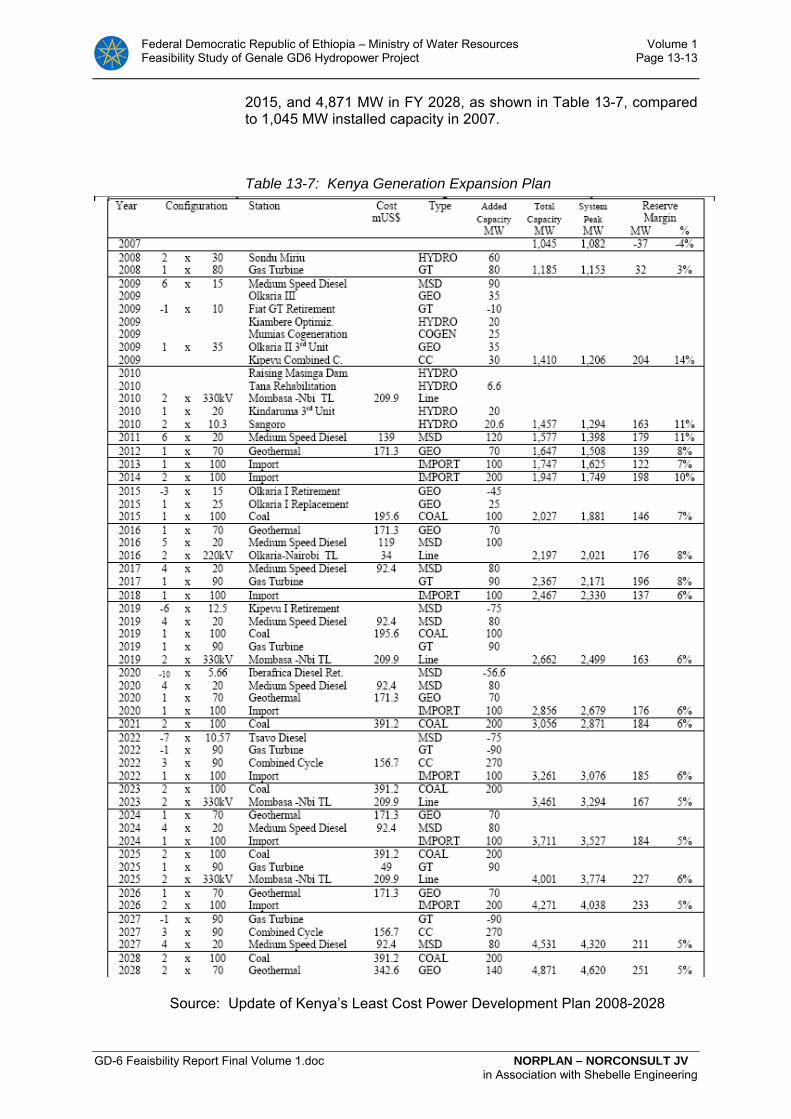
Federal Democratic Republic of Ethiopia – Ministry of Water Resources Volume 1 Feasibility Study of Genale GD6 Hydropower Project Page 13-13
GD-6 Feaisbility Report Final Volume 1.doc NORPLAN – NORCONSULT JV in Association with Shebelle Engineering
2015, and 4,871 MW in FY 2028, as shown in Table 13-7, compared to 1,045 MW installed capacity in 2007.
Table 13-7: Kenya Generation Expansion Plan
Source: Update of Kenya’s Least Cost Power Development Plan 2008-2028

Federal Democratic Republic of Ethiopia – Ministry of Water Resources Volume 1 Feasibility Study of Genale GD6 Hydropower Project Page 13-14
GD-6 Feaisbility Report Final Volume 1.doc NORPLAN – NORCONSULT JV in Association with Shebelle Engineering
13.3 Costs of Supply Alternatives 8
At the present time, most attention is being focused on new, and as yet uncommitted, hydropower projects on the following river basins:
• The Gibe River and its tributaries with the Gilgel Gibe (Stages Ill and IV) and Halele-Werabesa (Stages I and II) hydropower projects;
• The Abay River (Blue Nile) and its tributaries with the Che-moga-Yeda (Stages I and 11) and the main Abay River hy-dropower projects (Karadobi, Mendaia and Border);
• Baro-Akobo River with the Baro (Stages I, II and Genji Di-version) hydropower project
• Genale-Dawa River Basin with, inter alia, Genale GD-3 and GD-6.
Hydropower projects on other rivers are also being promoted, but the above river basins are currently yielding hydropower projects with at-tractively low unit generation costs and projects along the first three rivers listed above will compete with GD-3 and GD-6 for implementa-tion. Of the above schemes, those that have been studied to a level sufficient to define the principal cost and performance parameters are as shown in Table 13-8.
8 In addition to the Pre-feasibility Studies GD-6 Hydropower Project, Lahmeyer, 2006, this section
draws on the Feasibility Studies Genale (GD-3) Multipurpose Hydropower Project, Lahmeyer International, 2007.
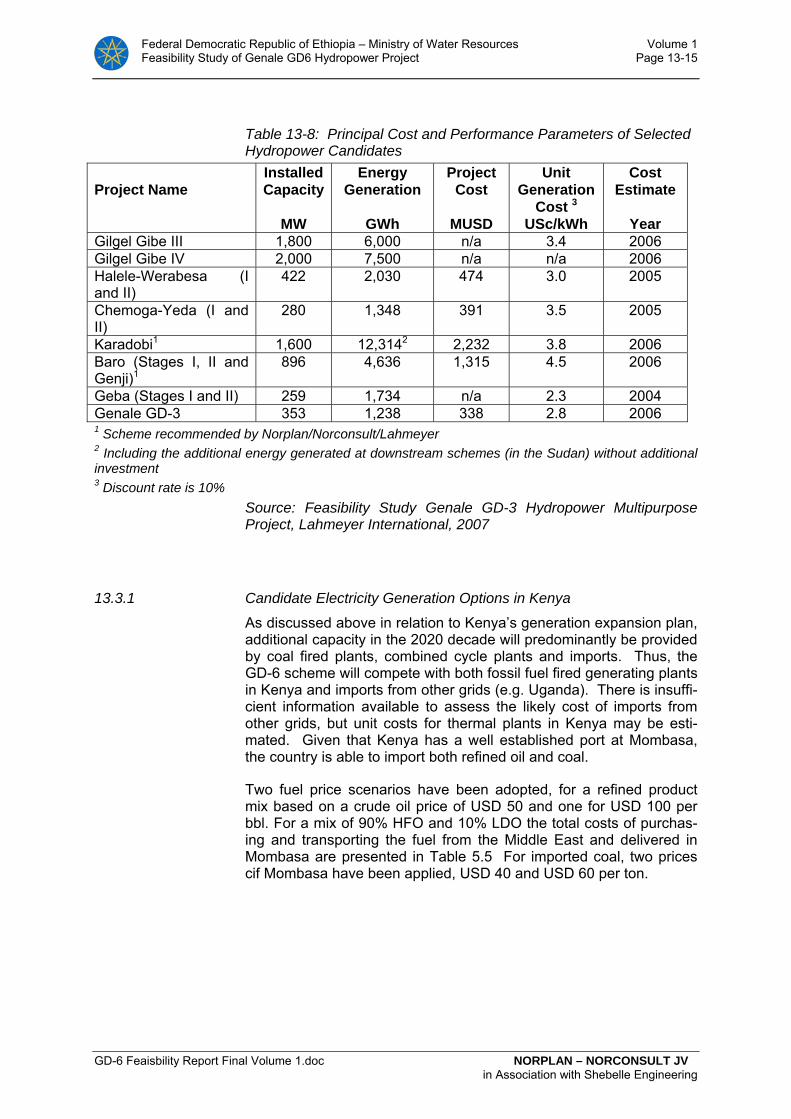
Federal Democratic Republic of Ethiopia – Ministry of Water Resources Volume 1 Feasibility Study of Genale GD6 Hydropower Project Page 13-15
GD-6 Feaisbility Report Final Volume 1.doc NORPLAN – NORCONSULT JV in Association with Shebelle Engineering
Table 13-8: Principal Cost and Performance Parameters of Selected Hydropower Candidates
Project Name
Installed Capacity
MW
Energy Generation
GWh
Project Cost
MUSD
Unit Generation
Cost 3 USc/kWh
Cost Estimate
Year
Gilgel Gibe III 1,800 6,000 n/a 3.4 2006 Gilgel Gibe IV 2,000 7,500 n/a n/a 2006 Halele-Werabesa (I and II)
422 2,030 474 3.0 2005
Chemoga-Yeda (I and II)
280 1,348 391 3.5 2005
Karadobi1 1,600 12,3142 2,232 3.8 2006 Baro (Stages I, II and Genji)1
896 4,636 1,315 4.5 2006
Geba (Stages I and II) 259 1,734 n/a 2.3 2004 Genale GD-3 353 1,238 338 2.8 2006 1 Scheme recommended by Norplan/Norconsult/Lahmeyer 2 Including the additional energy generated at downstream schemes (in the Sudan) without additional investment 3 Discount rate is 10% Source: Feasibility Study Genale GD-3 Hydropower Multipurpose
Project, Lahmeyer International, 2007
13.3.1 Candidate Electricity Generation Options in Kenya
As discussed above in relation to Kenya’s generation expansion plan, additional capacity in the 2020 decade will predominantly be provided by coal fired plants, combined cycle plants and imports. Thus, the GD-6 scheme will compete with both fossil fuel fired generating plants in Kenya and imports from other grids (e.g. Uganda). There is insuffi-cient information available to assess the likely cost of imports from other grids, but unit costs for thermal plants in Kenya may be esti-mated. Given that Kenya has a well established port at Mombasa, the country is able to import both refined oil and coal.
Two fuel price scenarios have been adopted, for a refined product mix based on a crude oil price of USD 50 and one for USD 100 per bbl. For a mix of 90% HFO and 10% LDO the total costs of purchas-ing and transporting the fuel from the Middle East and delivered in Mombasa are presented in Table 5.5 For imported coal, two prices cif Mombasa have been applied, USD 40 and USD 60 per ton.
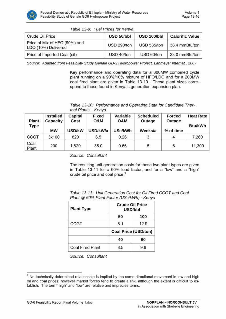
Federal Democratic Republic of Ethiopia – Ministry of Water Resources Volume 1 Feasibility Study of Genale GD6 Hydropower Project Page 13-16
GD-6 Feaisbility Report Final Volume 1.doc NORPLAN – NORCONSULT JV in Association with Shebelle Engineering
Table 13-9: Fuel Prices for Kenya
Crude Oil Price USD 50/bbl USD 100/bbl Calorific Value Price of Mix of HFO (90%) and LDO (10%) Delivered USD 290/ton USD 535/ton 38.4 mmBtu/ton
Price of Imported Coal (cif) USD 40/ton USD 60/ton 23.0 mmBtu/ton
Source: Adapted from Feasibility Study Genale GD-3 Hydropower Project, Lahmeyer Internat., 2007
Key performance and operating data for a 300MW combined cycle plant running on a 90%/10% mixture of HFO/LDO and for a 200MW coal fired plant are given in Table 13-10. These plant sizes corre-spond to those found in Kenya’s generation expansion plan.
Table 13-10: Performance and Operating Data for Candidate Ther-mal Plants – Kenya
Plant Type
Installed Capacity
MW
Capital Cost
USD/kW
Fixed O&M
USD/kW/a
Variable O&M
USc/kWh
Scheduled Outage
Weeks/a
Forced Outage
% of time
Heat Rate
Btu/kWh
CCGT 3x100 820 6.5 0.26 3 4 7,260 Coal Plant 200 1,820 35.0 0.66 5 6 11,300
Source: Consultant
The resulting unit generation costs for these two plant types are given in Table 13-11 for a 60% load factor, and for a “low” and a “high” crude oil price and coal price.9
Table 13-11: Unit Generation Cost for Oil Fired CCGT and Coal Plant @ 60% Plant Factor (USc/kWh) - Kenya Plant Type
Crude Oil Price USD/bbl
50 100 CCGT 8.1 12.9
Coal Price (USD/ton)
40 60
Coal Fired Plant 8.5 9.6
Source: Consultant
9 No technically determined relationship is implied by the same directional movement in low and high oil and coal prices; however market forces tend to create a link, although the extent is difficult to es-tablish. The term” high” and “low” are relative and imprecise terms.
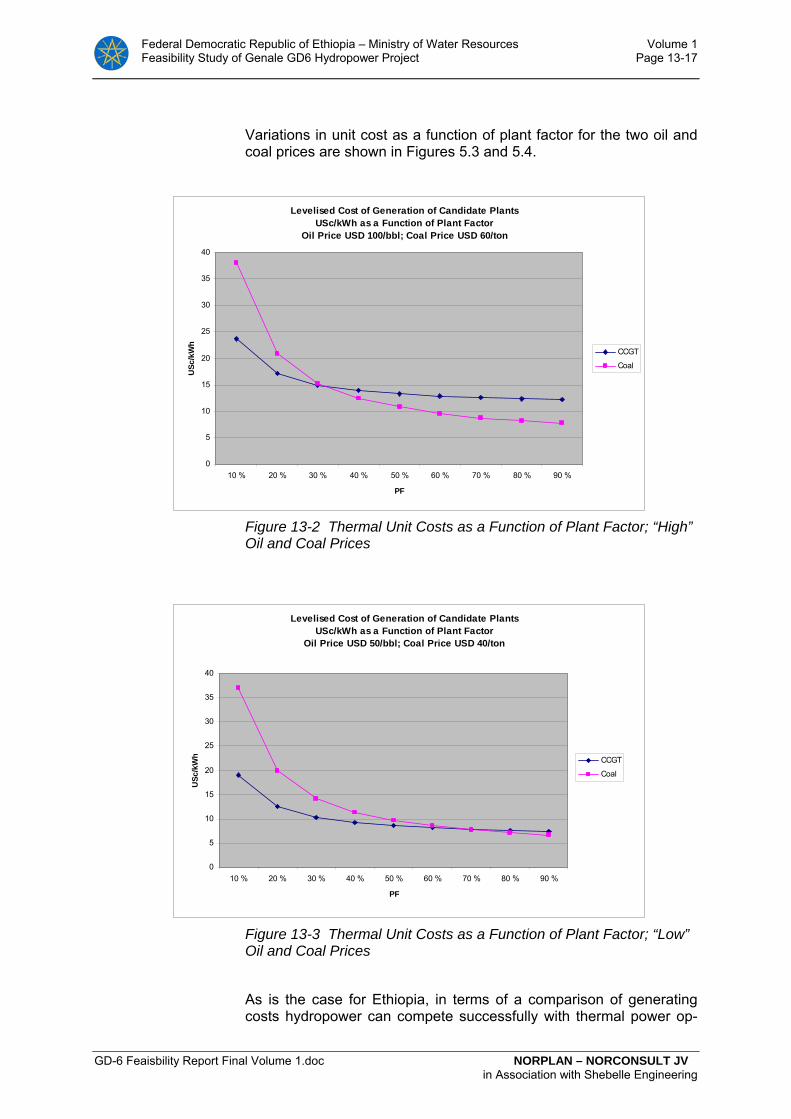
Federal Democratic Republic of Ethiopia – Ministry of Water Resources Volume 1 Feasibility Study of Genale GD6 Hydropower Project Page 13-17
GD-6 Feaisbility Report Final Volume 1.doc NORPLAN – NORCONSULT JV in Association with Shebelle Engineering
Variations in unit cost as a function of plant factor for the two oil and coal prices are shown in Figures 5.3 and 5.4.
Levelised Cost of Generation of Candidate Plants USc/kWh as a Function of Plant Factor
Oil Price USD 100/bbl; Coal Price USD 60/ton
0
5
10
15
20
25
30
35
40
10 % 20 % 30 % 40 % 50 % 60 % 70 % 80 % 90 %
PF
USc
/kW
h
CCGT
Coal
Figure 13-2 Thermal Unit Costs as a Function of Plant Factor; “High” Oil and Coal Prices
Levelised Cost of Generation of Candidate Plants USc/kWh as a Function of Plant Factor
Oil Price USD 50/bbl; Coal Price USD 40/ton
0
5
10
15
20
25
30
35
40
10 % 20 % 30 % 40 % 50 % 60 % 70 % 80 % 90 %
PF
USc
/kW
h CCGT
Coal
Figure 13-3 Thermal Unit Costs as a Function of Plant Factor; “Low” Oil and Coal Prices
As is the case for Ethiopia, in terms of a comparison of generating costs hydropower can compete successfully with thermal power op-

Federal Democratic Republic of Ethiopia – Ministry of Water Resources Volume 1 Feasibility Study of Genale GD6 Hydropower Project Page 13-18
GD-6 Feaisbility Report Final Volume 1.doc NORPLAN – NORCONSULT JV in Association with Shebelle Engineering
tions in Kenya based on imported fuel. However, a direct comparison of the figures cannot be made for Kenya as two further factors need to be taken into consideration10:
• Kenya as a buyer would expect a discount in relation to its avoided thermal costs, to account for the greater risk asso-ciated with dependence on imports and to allow both par-ties to gain from power trade11;
• Likely higher cost of transmission associated with imports than for domestic generation, which would affect the cost comparisons. (In the next chapter the cost of the Ethiopian-Kenyan Transmission Line as to the Interconnection Study will be referred.)
13.3.2 Conclusion
In Ethiopia, the viable alternatives, or competitors to GD-6 are fossil fuel fired power plants and other domestic hydropower schemes. The viable fossil fuel fired plants would generate electricity at about be-tween USc 9.0 and 14.5 per kWh at a plant factor of 60%, depending on crude oil prices. The planned hydropower schemes would gener-ate electricity at between USc 2.5 and 4.5 per kWh.
In Kenya, the hydropower resources are largely exhausted and ac-cording to the current expansion plan, electricity will have to be im-ported and new thermal plant commissioned. The viable alternatives (or competitors) to GD-6 in Kenya are fossil fuel fired power plants. The most attractive fossil fuel fired plants would generate electricity at around between USc 8.0 and 13.0 per kWh at a plant factor of 60%, depending on fuel prices.
From the above it is clear that GD-6 could supply the electricity mar-kets in both Ethiopia and in Kenya. Although the generation expan-sion targets set in Ethiopia will require massive investments in new generating capacity, there are several very attractive hydropower schemes in the planning pipeline; in other words competition should be stronger in Ethiopia than in Kenya. In Kenya, hydropower re-sources have been largely exhausted and competitors of GD-6 will be expensive fossil fuel fired plant.12
13.4 Cost of Transmission to Kenya
Cost of transmission to Kenya has recently been studied to feasibili-tyy level in the report “The Ethiopia-Kenya Power Systems Intercon-
10 As far as transmission costs, this applies also to Ethiopia, although distances and the difference between these for the different generating options would be smaller than for exports to Kenya.
11 On the other hand, imported hydropower from Ethiopia could imply greater price stability, and thereby lesser risk, than for domestic options based on imported oil or coal.
12 Plus possibly geothermal energy at costs that are not readily available.

Federal Democratic Republic of Ethiopia – Ministry of Water Resources Volume 1 Feasibility Study of Genale GD6 Hydropower Project Page 13-19
GD-6 Feaisbility Report Final Volume 1.doc NORPLAN – NORCONSULT JV in Association with Shebelle Engineering
nection Project”. This was referred to in Chapter 13.1 above as the In-terconnection Study (Fichtner, 2009). The report suggests a 500 kV DC line from the substation Wolayta/Sodo on the Ethiopian side in connection with the Gilgel Gibe III project, to Longonat substation outside Nairobi. The length of the main line is 1066 km. In addition are there 400 kV connection lines to the two substations of which 55 km are in Ethiopia and 80 km in Kenya respectively, which make the total length of the line about 1200 km.
It is suggested being developed in two stages, Phase 1 for 1000 MW transfer capacity in 2012 in connection with the commissioning of Gilgel Gibe III, which will result in a considerably power surplus in Ethiopia from that year, and another 1000 MW in Phase 2 from 2020.
The cost of the line is estimated at EUR 595 mill in Phase 1 and EUR 202 mill in Phase 2, a total of EUR 797 mill. Ca 41.2 % of the costs in Phase 1 originates in Ethiopia, 48.0 % in Phase 2, and in total 42.9 % (EUR 342 mill) falls on the Ethiopian part. In Table 13-12 the corre-spondent costs of the line in USD is indicated.
Table 13-12: Cost of Interconnection Line HVDC Ethiopia-Kenya (from Wolayta to Longonot). Costs indicated in MUSD
Ethiopia Kenya Total
Phase 1 318.5 455.0 773.5
Phase 2 126.1 136.5 262.6
Total 444.6 591.5 1036.1
Source: Fichtner 2009. Converted to USD at an exchange rate of 1.3 USD per EUR (as per 17th of March 2009) by the Consultant.
The studies are made under various assumptions of combined export to other countries as follows:
• Sudan, scaled up from 100 MW (788 GWh) in 2009 to 1200 MW (9800 GWh) in 2020
• Djibouti 100 MW (788 GWh from 2010)
• Egypt 700 MW (5200 GWh) from 2020.
These options result in different availabilities for export to Kenya. It is also assumed options with export to other countries via Kenya.
In Phase 1, over the years 2012 – 2019, it is assumed that the export to Kenya increases from 2503 GWh to 5729 GWh (less small frac-tions, max 34 GWh, of opposite energy flow).
In Phase 2, over the period 2020 – 2027 there are studied two op-tions,

Federal Democratic Republic of Ethiopia – Ministry of Water Resources Volume 1 Feasibility Study of Genale GD6 Hydropower Project Page 13-20
GD-6 Feaisbility Report Final Volume 1.doc NORPLAN – NORCONSULT JV in Association with Shebelle Engineering
a) 1200 MW to Sudan, the export to Kenya increases from 7657 GWh to 10541 GWh (less small fractions of opposite flow)
b) 1200 MW to Sudan and 700 MW to Egypt, the export to Kenya in-creases from 5436 GWh to 8002 (less small fractions of opposite flow)
By different combinations of these export options the Interconnection Study has estimated the economic and financial results of three sce-narios for export to Kenya:
Scenarios:
• Case 1: Export to Kenya only, in line with Kenya’s growing demand for import over the project horizon
• Case 2: Export to other countries also via Kenya
• Case 3: The Interconnection line is “fully” utilized continuously with 6,000 hours a year from the commissioning date.
The economic and financial results of the interconnection line were not made fully available to the Consultant from EEPCO’s side at the time of writing (since EEPCo had just received the report them-selves), but were indicated as follows:
• EIRR: 23.5 – 25.0 % at a discount rate of 12 %
• B/C ratio: 1.43 – 1.57
• For EEPCO: FIRR 20.8 – 22.0 %, and payback 8-9 years
• For KPLC: FIRR ca. 17.2 – 17.8 %, and payback 11–13 years
• The levelized cost of interconnection 1.37 – 1.87 USc/kWh (the annualized and discounted cost per kWh)
• Equalized Bulk Tariff: 5.70 – 5.9 USc/kWh. (The market clear-ing price between Kenya (KPLC)’s maximum willingness to pay for supply options less costs of interconnection, and Ethiopia (EEPCo)’ minimum sales price requirements (the value if the energy is sold to ICS) plus costs of interconnec-tion, The gap between KPLC’s maximum price and EEPCo’s minimum price is about 1.8 – 2.1 USc/kWh in three different cases.
Of these results, the last two; the “Levelized cost of interconnection” and the “Equalized bulk tariff”, have been assumed as input data in the Economic and Financial analyses of GD-6 by the averages of the three scenarios, with the respective values of 1.6 USc/kWh and 5.85 USc/kWh. These makes up the (sales) value of the power from GD-6 referred at Sodo substation to be 5.16 USc/kWh for Export and 4.21 USc/kWh for power produced for the internal market. The calculation is shown in Table 13-13 below.
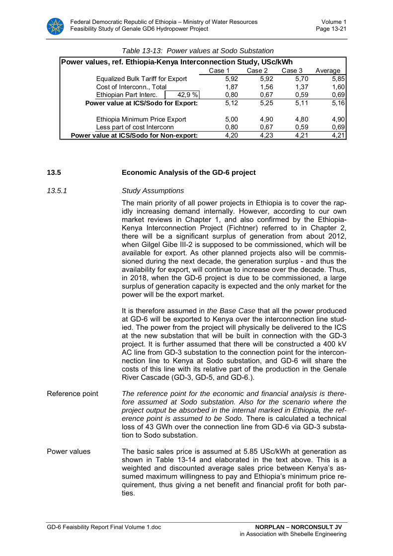
Federal Democratic Republic of Ethiopia – Ministry of Water Resources Volume 1 Feasibility Study of Genale GD6 Hydropower Project Page 13-21
GD-6 Feaisbility Report Final Volume 1.doc NORPLAN – NORCONSULT JV in Association with Shebelle Engineering
Table 13-13: Power values at Sodo Substation Power values, ref. Ethiopia-Kenya Interconnection Study, USc/kWh
Case 1 Case 2 Case 3 AverageEqualized Bulk Tariff for Export 5,92 5,92 5,70 5,85Cost of Interconn., Total 1,87 1,56 1,37 1,60Ethiopian Part Interc. 42,9 % 0,80 0,67 0,59 0,69
Power value at ICS/Sodo for Export: 5,12 5,25 5,11 5,16
Ethiopia Minimum Price Export 5,00 4,90 4,80 4,90Less part of cost Interconn 0,80 0,67 0,59 0,69
Power value at ICS/Sodo for Non-export: 4,20 4,23 4,21 4,21
13.5 Economic Analysis of the GD-6 project
13.5.1 Study Assumptions
The main priority of all power projects in Ethiopia is to cover the rap-idly increasing demand internally. However, according to our own market reviews in Chapter 1, and also confirmed by the Ethiopia-Kenya Interconnection Project (Fichtner) referred to in Chapter 2, there will be a significant surplus of generation from about 2012, when Gilgel Gibe III-2 is supposed to be commissioned, which will be available for export. As other planned projects also will be commis-sioned during the next decade, the generation surplus - and thus the availability for export, will continue to increase over the decade. Thus, in 2018, when the GD-6 project is due to be commissioned, a large surplus of generation capacity is expected and the only market for the power will be the export market.
It is therefore assumed in the Base Case that all the power produced at GD-6 will be exported to Kenya over the interconnection line stud-ied. The power from the project will physically be delivered to the ICS at the new substation that will be built in connection with the GD-3 project. It is further assumed that there will be constructed a 400 kV AC line from GD-3 substation to the connection point for the intercon-nection line to Kenya at Sodo substation, and GD-6 will share the costs of this line with its relative part of the production in the Genale River Cascade (GD-3, GD-5, and GD-6.).
Reference point The reference point for the economic and financial analysis is there-fore assumed at Sodo substation. Also for the scenario where the project output be absorbed in the internal marked in Ethiopia, the ref-erence point is assumed to be Sodo. There is calculated a technical loss of 43 GWh over the connection line from GD-6 via GD-3 substa-tion to Sodo substation.
Power values The basic sales price is assumed at 5.85 USc/kWh at generation as shown in Table 13-14 and elaborated in the text above. This is a weighted and discounted average sales price between Kenya’s as-sumed maximum willingness to pay and Ethiopia’s minimum price re-quirement, thus giving a net benefit and financial profit for both par-ties.

Federal Democratic Republic of Ethiopia – Ministry of Water Resources Volume 1 Feasibility Study of Genale GD6 Hydropower Project Page 13-22
GD-6 Feaisbility Report Final Volume 1.doc NORPLAN – NORCONSULT JV in Association with Shebelle Engineering
In the Interconnection Study it has been assumed that firm power de-livered to Kenya has the value of avoided costs of coal power, while secondary power (non-firm) has the value of avoided operation and fuel costs of diesel generation.
A similar approach has been adopted in this analysis:
The GD-3 and GD-6 projects together will deliver about 3075 GWh firm energy out of a total average of 3301 GWh. The more projects the ICS engage in, the more reliable and less vulnerable the system will be for deficits in the precipitation. By the time that GD-6 will be commissioned, the generation into the ICS will come from many pro-jects spread over long distances over Ethiopia, and the commission-ing of GD-6 will add also a system benefit in form of increased reli-ability of the ICS. In addition, connection to the much larger thermal system in Kenya will make the system even more reliable, as long as the transmission lines have sufficient capacity.
Non-firm It is therefore reasonable to assume that a portion of the secondary power could have the value of firm power. However, the secondary power is, as shown, a relatively small portion, and as it may be as-sumed to have the high value of avoided costs of operating diesel generation (the Interconnection Study), it is assumed the same value as firm power in the economic and financial analyses.
Peak The GD-3 and GD-6 are designed with as high plant factor as about 0.75. Thus, they may be characterised as “base load” power plants. Considering peak values specifically is less important for this kind of power plants. Nevertheless, in the sensitivity analysis scenarios with higher and increasing power values have been made, and these could represent increasing value of peak power in Kenya over time.
SMHP For the small hydropower scheme that will deliver electricity to the local 33 kV network, a generation price of 5.0 UScents has been as-sumed. (It should be noted that in addition it will add a benefit to the local network as its inclusion will reduce the power losses in it.)
13.5.2 Methodology of Economic Analysis
Project period Economic and financial analyses have been calculated from year 1 and onwards, and all present values (PV) are referred to beginning of year 1. In EEPCo’s Generation Expansion Plan (Table 13-4) the Genale projects are assumed commissioned in 2018. In order to as-sume commissioning around 2018 with a construction period esti-mated to be 7 years, it is assumed project start-up at beginning of 2013 (Gregorian Calendar) with planning throughout most of the year and construction start-up in October. This is then year 1 in the calcu-lation model. The first turbine will start its production mid-year 2019, and full production is assumed from beginning of 2020. The small hy-dro for local deliveries is assumed start up production primo year 2019.
The economic analysis has been calculated over a project horizon of 48 years, whereas about the last 40 years cover the project in opera-tion.

Federal Democratic Republic of Ethiopia – Ministry of Water Resources Volume 1 Feasibility Study of Genale GD6 Hydropower Project Page 13-23
GD-6 Feaisbility Report Final Volume 1.doc NORPLAN – NORCONSULT JV in Association with Shebelle Engineering
Discount rate The primary discount rate applied in the economic analysis, 10.23% real, is in accordance with recommendations for general investment analysis given by the Ministry of Finance and Economic Development in its guidelines National Economic Parameters and Conversion Fac-tors for Ethiopia of June 2008 (MoFED 2008). The rate of 10 % was applied in the Feasibility Study for GD-3.
Conversion Factors Economic analysis differs from Financial analysis in that use of re-sources should be valued at economic prices (sometimes called “shadow prices”), which of many reasons may differ from the market prices. In (MoFED 2008) there is therefore indicated a list of conver-sion factors (CF) for different kind of industries, use of domestic re-sources, and at different aggregated sector levels. These guidelines should be used in valuation of domestic resources when studying economic analyses of projects in order to reflect the real value of the project for the society.
With reference to (MOFED 2008) the following conversion factors were chosen to be relevant for this analysis:
CF for local labour is assumed at 0.63 (assumed 70% skilled labour) as a weighted average of the CFs under the World Price Numeraire (MoFED 2008) It is reasoned by that not all local labour have high opportunity costs.
For other local costs the CF has been assumed at 0.9 in accordance with the CF for Domestic Resources under the World Price Nu-meraire. It is reasoned by that domestic resources in total have only 90 % opportunity costs.
Foreign exchange is a scarce resource in Ethiopia. In the sensitivity analysis it has therefore been run a scenario with a CF of 1.11 for foreign exchange in accordance with the CF for foreign exchange un-der the Domestic Price Numeraire. Since the project is assumed to export power to Kenya and thus generate foreign exchange, the power value has been added this conversion factor in this scenario. The tariff increased from 5.16 to 5.73 USc/kWh. A correspondent CF was added on the costs side, i.e. interests to be paid on the interna-tional credits. (The foreign exchange needed for the purchase of the international costs of investments is assumed being covered by con-cessional credits. The flow of foreign exchange in this connection is therefore a nil-sum.)
Costs The investment cost of the project is basically estimated at nearly USD 470 mill, whereas the local part has a value of USD 164 mill. Ad-justed for the conversion factor for local labour, local and total costs declined with USD 24 mill. The total cost applied in the economic analysis is therefore USD 445.4 mill, whereas local costs make up USD 139.3 mill.
Costs of operation and maintenance (O&M) are assumed to be 0.8 % of the investments plus 0.2 UScent/kWh produced.
Price levels All costs and prices throughout the economic analysis are calculated with real price level of ultimo 2008. VAT, import tax and duties are not
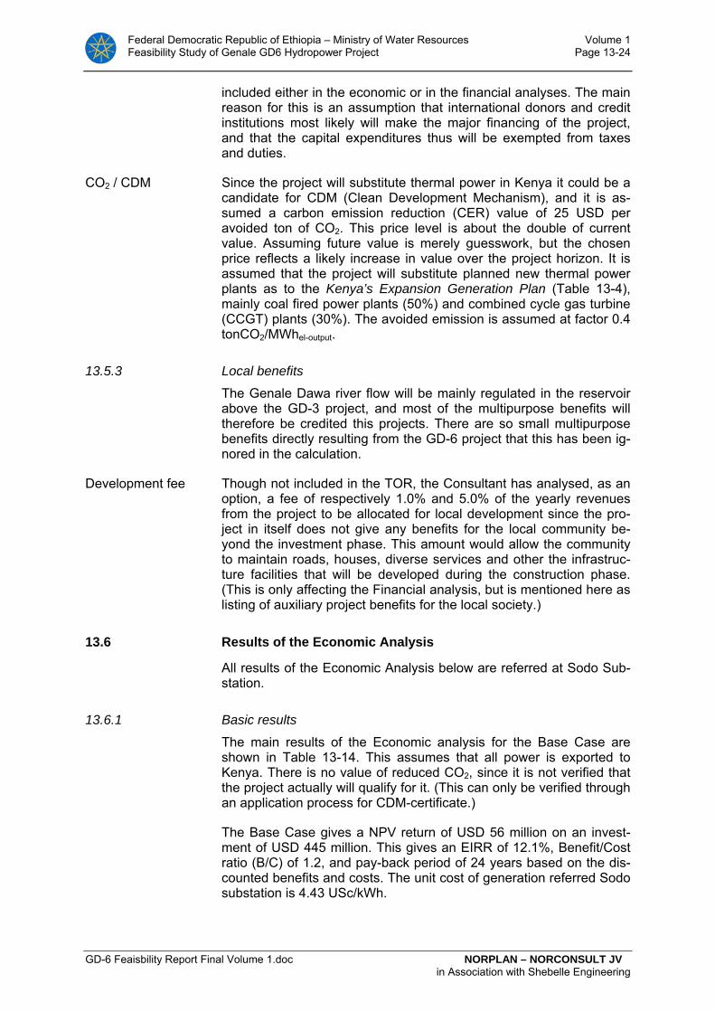
Federal Democratic Republic of Ethiopia – Ministry of Water Resources Volume 1 Feasibility Study of Genale GD6 Hydropower Project Page 13-24
GD-6 Feaisbility Report Final Volume 1.doc NORPLAN – NORCONSULT JV in Association with Shebelle Engineering
included either in the economic or in the financial analyses. The main reason for this is an assumption that international donors and credit institutions most likely will make the major financing of the project, and that the capital expenditures thus will be exempted from taxes and duties.
CO2 / CDM Since the project will substitute thermal power in Kenya it could be a candidate for CDM (Clean Development Mechanism), and it is as-sumed a carbon emission reduction (CER) value of 25 USD per avoided ton of CO2. This price level is about the double of current value. Assuming future value is merely guesswork, but the chosen price reflects a likely increase in value over the project horizon. It is assumed that the project will substitute planned new thermal power plants as to the Kenya’s Expansion Generation Plan (Table 13-4), mainly coal fired power plants (50%) and combined cycle gas turbine (CCGT) plants (30%). The avoided emission is assumed at factor 0.4 tonCO2/MWhel-output.
13.5.3 Local benefits
The Genale Dawa river flow will be mainly regulated in the reservoir above the GD-3 project, and most of the multipurpose benefits will therefore be credited this projects. There are so small multipurpose benefits directly resulting from the GD-6 project that this has been ig-nored in the calculation.
Development fee Though not included in the TOR, the Consultant has analysed, as an option, a fee of respectively 1.0% and 5.0% of the yearly revenues from the project to be allocated for local development since the pro-ject in itself does not give any benefits for the local community be-yond the investment phase. This amount would allow the community to maintain roads, houses, diverse services and other the infrastruc-ture facilities that will be developed during the construction phase. (This is only affecting the Financial analysis, but is mentioned here as listing of auxiliary project benefits for the local society.)
13.6 Results of the Economic Analysis
All results of the Economic Analysis below are referred at Sodo Sub-station.
13.6.1 Basic results
The main results of the Economic analysis for the Base Case are shown in Table 13-14. This assumes that all power is exported to Kenya. There is no value of reduced CO2, since it is not verified that the project actually will qualify for it. (This can only be verified through an application process for CDM-certificate.)
The Base Case gives a NPV return of USD 56 million on an invest-ment of USD 445 million. This gives an EIRR of 12.1%, Benefit/Cost ratio (B/C) of 1.2, and pay-back period of 24 years based on the dis-counted benefits and costs. The unit cost of generation referred Sodo substation is 4.43 USc/kWh.

Federal Democratic Republic of Ethiopia – Ministry of Water Resources Volume 1 Feasibility Study of Genale GD6 Hydropower Project Page 13-25
GD-6 Feaisbility Report Final Volume 1.doc NORPLAN – NORCONSULT JV in Association with Shebelle Engineering
It should be noted that since the EIRR is just over 12.0%, a discount rate of 12.0% would also give a slightly positive NPV.
Table 13-14: Economic Main Results of Base Case. 100% Export to Kenya
Energy cost 4.43 US cent/kWh Annualized cost per kWh at ICS/Sodo Substation
NPV 56 USD mill. Net Present Value
EIRR 12.1% Economic Internal Rate of Return
Payback 24 years Payback period
B/C 1.2 Benefit - Cost ratio
13.6.2 Sensitivity Analyses
Sensitivity analyses were run on the Base Case only. The following 6 analyses have been done, one at a time:
1. Export with CO2 value (adding 1.0 UScent to the bulk tariff), which also corresponds to about Kenya’s maximum willingness to pay without a CO2 value (+0.95 UScent)
2. 2% yearly growth in Kenya’s costs for variable O&M in their ther-mal power plants (fuel, variable O&M and CO2-values), which re-sults in corresponding increase in WTP and bulk tariff for Ethiopian power.
3. Conversion Factor of 1.11 for foreign exchange in the power value
4. Pro rata increase of 10% on all project costs
5. 5 % less production (less water availability)
6. All power applied in the ICS for covering internal demand
The results of the Base Case and Sensitivity analyses are shown in the tables above and below and the calculations behind in the Annex 3H, Appendix pages 1 – 9.
Table 13-15: Sensitivity analysis 1: Export to Kenya, CO2-value in-cluded
Energy cost 4.43 US cent/kWh Annualized cost per kWh at ICS/Sodo Substation
NPV 132 USD mill. Net Present Value
EIRR 14.4% Economic Internal Rate of Return
Payback 17 years Payback period
B/C 1.4 Benefit - Cost ratio
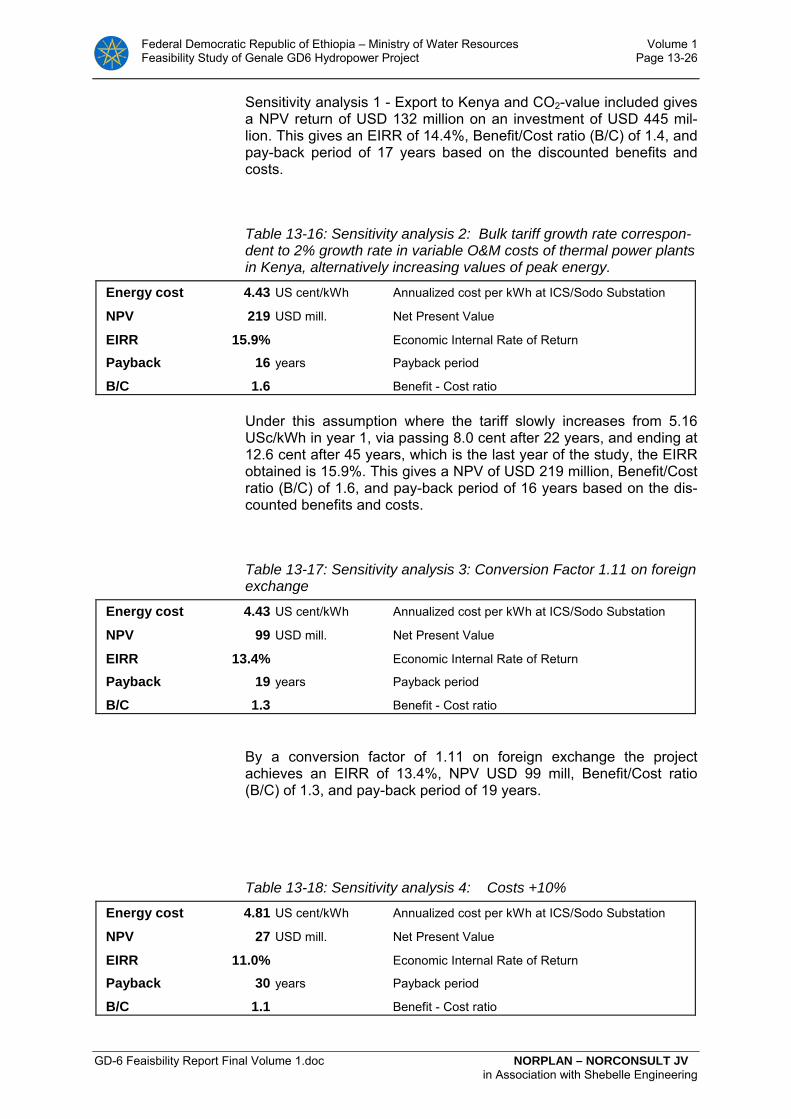
Federal Democratic Republic of Ethiopia – Ministry of Water Resources Volume 1 Feasibility Study of Genale GD6 Hydropower Project Page 13-26
GD-6 Feaisbility Report Final Volume 1.doc NORPLAN – NORCONSULT JV in Association with Shebelle Engineering
Sensitivity analysis 1 - Export to Kenya and CO2-value included gives a NPV return of USD 132 million on an investment of USD 445 mil-lion. This gives an EIRR of 14.4%, Benefit/Cost ratio (B/C) of 1.4, and pay-back period of 17 years based on the discounted benefits and costs.
Table 13-16: Sensitivity analysis 2: Bulk tariff growth rate correspon-dent to 2% growth rate in variable O&M costs of thermal power plants in Kenya, alternatively increasing values of peak energy.
Energy cost 4.43 US cent/kWh Annualized cost per kWh at ICS/Sodo Substation
NPV 219 USD mill. Net Present Value
EIRR 15.9% Economic Internal Rate of Return
Payback 16 years Payback period
B/C 1.6 Benefit - Cost ratio
Under this assumption where the tariff slowly increases from 5.16 USc/kWh in year 1, via passing 8.0 cent after 22 years, and ending at 12.6 cent after 45 years, which is the last year of the study, the EIRR obtained is 15.9%. This gives a NPV of USD 219 million, Benefit/Cost ratio (B/C) of 1.6, and pay-back period of 16 years based on the dis-counted benefits and costs.
Table 13-17: Sensitivity analysis 3: Conversion Factor 1.11 on foreign exchange
Energy cost 4.43 US cent/kWh Annualized cost per kWh at ICS/Sodo Substation
NPV 99 USD mill. Net Present Value
EIRR 13.4% Economic Internal Rate of Return
Payback 19 years Payback period
B/C 1.3 Benefit - Cost ratio
By a conversion factor of 1.11 on foreign exchange the project achieves an EIRR of 13.4%, NPV USD 99 mill, Benefit/Cost ratio (B/C) of 1.3, and pay-back period of 19 years.
Table 13-18: Sensitivity analysis 4: Costs +10%
Energy cost 4.81 US cent/kWh Annualized cost per kWh at ICS/Sodo Substation
NPV 27 USD mill. Net Present Value
EIRR 11.0% Economic Internal Rate of Return
Payback 30 years Payback period
B/C 1.1 Benefit - Cost ratio

Federal Democratic Republic of Ethiopia – Ministry of Water Resources Volume 1 Feasibility Study of Genale GD6 Hydropower Project Page 13-27
GD-6 Feaisbility Report Final Volume 1.doc NORPLAN – NORCONSULT JV in Association with Shebelle Engineering
With increase of 10% pro rata in all costs, the EIRR achieved is 11.0%, thus still economic feasible at a discount rate of 10.23%. However, it would not be feasible with discount rate 12%. The NPV achieved would be USD 27 million. The unit energy costs would in-crease to 4.8 UScent/kWh.
Table 13-19: Sensitivity analysis 5: 5 % less inflow to the GD-3 and GD-6 reservoirs than in the Base Case.
Energy cost 4.66 US cent/kWh Annualized cost per kWh at ICS/Sodo Substation
NPV 37 USD mill. Net Present Value
EIRR 11.5% Economic Internal Rate of Return
Payback 27 years Payback period
B/C 1.1 Benefit - Cost ratio
Under this assumption where there are 5 % less inflow to the GD-3 and GD-6 reservoirs the unit energy cost increases to over 4.6 USc/kWh. The project is still feasible with an EIRR of 11.5%, NPV at USD 37 million, Benefit/Cost ratio (B/C) of 1.1, and pay-back period of 27 years based on the discounted benefits and costs. The project would not be feasible with a discount rate of 12%.
Table 13-20: Sensitivity analysis 6: ICS internally Ethiopia (no ex-port)
Energy cost 4.43 US cent/kWh Annualized cost per kWh at ICS/Sodo Substation
NPV -16 USD mill. Net Present Value
EIRR 9.7% Economic Internal Rate of Return
Payback n. a. years Payback period
B/C 1.0 Benefit - Cost ratio
For coverage of internal demand only the project results are not fea-sible giving slightly negative NPV and EIRR below the discount rate.
The Minimum Export to Kenya that makes the project feasible
By 23% of the generation referred at Sodo for export to Kenya, the results are break even and on the border feasible with NPV = 0, EIRR 10.23% and B/C = 1.0.
Reduction in bulk tariff to Kenya
The assumed export bulk tariff at Sodo substation in the Base Case is 5.16 USc/kWh, while the energy cost of generation is 4.43 USc/kWh. This margin of 0.73 cents is 16.4% of the unit cost of gen-eration, and 14.1% of the assumed tariff. This means that the project can bear a tariff reduction of up to ca. 14% before break even is reached, and export becomes economically unfeasible.

Federal Democratic Republic of Ethiopia – Ministry of Water Resources Volume 1 Feasibility Study of Genale GD6 Hydropower Project Page 13-28
GD-6 Feaisbility Report Final Volume 1.doc NORPLAN – NORCONSULT JV in Association with Shebelle Engineering
13.6.3 Conclusion of the Economic Analysis
The Base Case project is economically feasible with a discount rate of 10.23%. Since the resulting EIRR is 12.1% the project would be on the border feasible with a discount rate of 12%. On the other side, with a discount rate of 12%, negative sensitivity assumptions will then make the project unfeasible.
The project has proven solid results towards the sensitivity analyses. It can bear relatively large cost increases and less inflow of water to the reservoirs. Finally, it can bear tariff reductions for Kenyan export of up to 14% before break even is reached.
The only negative result of the sensitivity analysis is in the case where all generation is applied for covering internal demand in Ethio-pia. However, with not more than 23% of the generation sold to Kenya the project reaches break-even with an EIRR at 10.23%. From this it may be concluded that the project is not feasible without the Interconnection line to Kenya, but if this be constructed, large parts of the generation might as well be sold internally in Ethiopia.
The main reasons that the project is feasible for export to Kenya and less feasible for internal coverage in Ethiopia may be summarised as follows:
• The value of (firm) energy is regarded higher in Kenya than in Ethiopia because Kenya’s internal generation development will have to be by thermal generation projects. These will have higher costs than Ethiopian hydropower options, particularly if there will be a value on the country’s CO2 emissions. If the unit generation costs of the interconnection line is lower than the difference in unit generation costs between Kenya and Ethiopia, the export is feasi-ble.
• The unit generation cost of GD-6 is higher than EEPCo’s assumed minimum price for export. The unit generation cost of GD-6 is higher than EEPCo’s assumed minimum price for export. There will therefore exist other hydropower projects in Ethiopia with lower unit generation costs (referred connection point to ICS) than GD-6.
13.7 Financial Analysis of the GD-6 project
13.7.1 Introduction and assumptions
Financial Analysis has been made for the Export alternative only, and the relevant assumptions of the Base Case in the Economic Analysis form the Base Case of the Financial Analysis as well. It is for example assumed that the sales price of the power is based on the same bulk tariffs as elaborated in the economic analysis. The project’s share of the cost of transmission from the power plant to Sodo substation is covered by the investor.
It is assumed an On-lending model with interest during construction (IDR). The basic financing is a combination of Concessional Credit (international soft loan), and equity on market conditions.

Federal Democratic Republic of Ethiopia – Ministry of Water Resources Volume 1 Feasibility Study of Genale GD6 Hydropower Project Page 13-29
GD-6 Feaisbility Report Final Volume 1.doc NORPLAN – NORCONSULT JV in Association with Shebelle Engineering
Equity It is assumed that the investor of the project will have to raise 20% of the investments in equity. For the remaining 80% capital needs the investor will achieve concessional credits.
Terms of financing The interest rate on equity is assumed 10% real. On the concessional credit, a soft loan model with 2% real interest rate is assumed. Terms from donors can be even lower, but it is assumed a small on-lending fee from the government to the project included. It is further assumed 10 years grace period and maturity (repayment) period of 30 years. The concessional part can also include a grant part of the investment.
For discounting future values in the PV calculations, the weighted av-erage of the interest rate on equity and on the loan is applied..
Financers The project could be an entirely Ethiopian Public owned project oper-ated by EEPCo, or a limited company with several share holders in-cluding EEPCo and international organisations and investors. Foreign organisations or investors could contribute with subsidised financing (soft loans or other means) and in return for these subsidies, require special outputs or terms for the project. There are many options for this, and this study cannot foresee such negotiations. Therefore, only one common on-lending model has been assumed.
It may be assumed that Kenya contributes to the financing by a Power-Purchase-Agreement (PPA) that guarantees their purchase of the power at certain terms. The PPA would be the base for seeking funding of either of the two models above.
Financial versus economic model
While economic analysis is based on the use and income of real re-sources, and values on parameters and variables should refer to the society’s valuation of these, the Financial analysis, on the other hand, shows the financial (money) flow of disbursements and income for the project.
Instead of discount rate, interest rate is used for discounting values, and in the financial analysis interests during construction (IDR) is re-levant and has been included.
Different kind of taxes could also be relevant for the financial analy-sis, but they will mostly be exempted in such projects according to the Ministry of Finance and Economic development (MoFED)
Apart from the above issues, there are no main differences between the economic and financial analyses in the study.
13.8 Results of the Financial Analysis
The Base Case model assumes 20% of the investment as conces-sional grants, 60% as concessional credit with 2.0% interest rate, and 20% of the investment as equity. This model gives a unit generation cost at only 2.19 USc/kWh, and when the net bulk tariff is assumed at 5.16 UScent, the margin is “formidable” with an FIRR of 32.7% on the investments, based on the “cash flow” of the project.
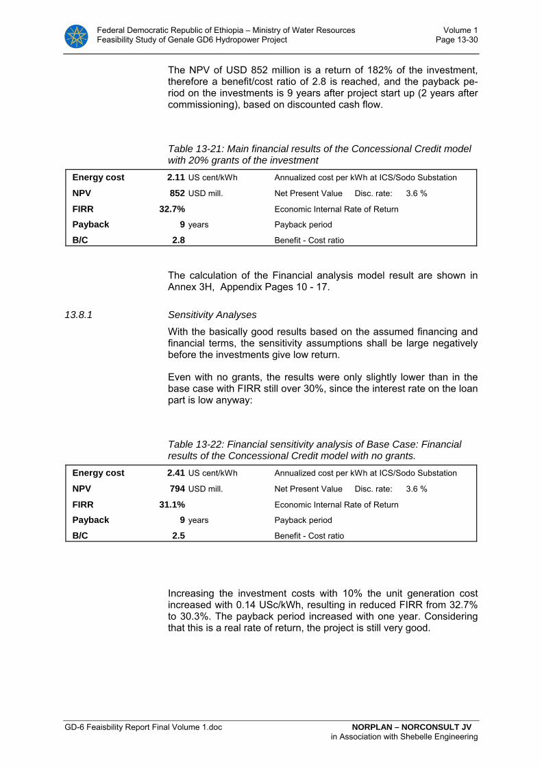
Federal Democratic Republic of Ethiopia – Ministry of Water Resources Volume 1 Feasibility Study of Genale GD6 Hydropower Project Page 13-30
GD-6 Feaisbility Report Final Volume 1.doc NORPLAN – NORCONSULT JV in Association with Shebelle Engineering
The NPV of USD 852 million is a return of 182% of the investment, therefore a benefit/cost ratio of 2.8 is reached, and the payback pe-riod on the investments is 9 years after project start up (2 years after commissioning), based on discounted cash flow.
Table 13-21: Main financial results of the Concessional Credit model with 20% grants of the investment
Energy cost 2.11 US cent/kWh Annualized cost per kWh at ICS/Sodo Substation
NPV 852 USD mill. Net Present Value Disc. rate: 3.6 %
FIRR 32.7% Economic Internal Rate of Return
Payback 9 years Payback period
B/C 2.8 Benefit - Cost ratio
The calculation of the Financial analysis model result are shown in Annex 3H, Appendix Pages 10 - 17.
13.8.1 Sensitivity Analyses
With the basically good results based on the assumed financing and financial terms, the sensitivity assumptions shall be large negatively before the investments give low return.
Even with no grants, the results were only slightly lower than in the base case with FIRR still over 30%, since the interest rate on the loan part is low anyway:
Table 13-22: Financial sensitivity analysis of Base Case: Financial results of the Concessional Credit model with no grants.
Energy cost 2.41 US cent/kWh Annualized cost per kWh at ICS/Sodo Substation
NPV 794 USD mill. Net Present Value Disc. rate: 3.6 %
FIRR 31.1% Economic Internal Rate of Return
Payback 9 years Payback period
B/C 2.5 Benefit - Cost ratio
Increasing the investment costs with 10% the unit generation cost increased with 0.14 USc/kWh, resulting in reduced FIRR from 32.7% to 30.3%. The payback period increased with one year. Considering that this is a real rate of return, the project is still very good.

Federal Democratic Republic of Ethiopia – Ministry of Water Resources Volume 1 Feasibility Study of Genale GD6 Hydropower Project Page 13-31
GD-6 Feaisbility Report Final Volume 1.doc NORPLAN – NORCONSULT JV in Association with Shebelle Engineering
Table 13-23: Financial sensitivity analysis of Base Case: Costs +10%
Energy cost 2.25 US cent/kWh Annualized cost per kWh at ICS/Sodo Substation
NPV 821 USD mill. Net Present Value Disc. rate: 3.6 %
FIRR 30.3% Economic Internal Rate of Return
Payback 10 years Payback period
B/C 2.6 Benefit - Cost ratio
The next sensitivity shows how 5 % less production (reason could be less inflow to the reservoirs, less demand or less production availabil-ity of technical reasons) affects the financial results. The energy cost increases from 2.11 to 2.21 USc/kWh, but with a net bulk tariff at 5.16 USc/kWh the project is still “formidable” with a NPV of USD 788 mill. and FIRR at 31.3 %.
Table 13-24: Financial sensitivity analysis of Base Case: Results of 5 % reduced energy production
Energy cost 2.21 US cent/kWh Annualized cost per kWh at ICS/Sodo Substation
NPV 788 USD mill. Net Present Value Disc. rate: 3.6 %
FIRR 31.3% Economic Internal Rate of Return
Payback 9 years Payback period
B/C 2.6 Benefit - Cost ratio
By sales to internal demand in Ethiopia only, the net tariff /sales price is reduced from 5.16 UScent/kWh to 4.21 UScent/kWh compared with export price to Kenya. This gives reduction of NPV from USD 852 mil-lion to 609 million, FIRR from 32.7% to 27.0%, and B/C from 2.7 to 2.3 compared with the results of the Basic model. The payback period increased from 9 to 10 years. It is assumed that all generation can be sold to the internal market at ICS.
Table 13-25: Results of sales to ICS internally in Ethiopia only
Energy cost 2.11 US cent/kWh Annualized cost per kWh at ICS/Sodo Substation
NPV 609 USD mill. Net Present Value Disc. rate: 3.6 %
FIRR 27.0% Economic Internal Rate of Return
Payback 10 years Payback period
B/C 2.3 Benefit - Cost ratio
In the next sensitivity analysis it is assumed that the investments to be done in year 7 is stretched over the years 7 and year 8. The first
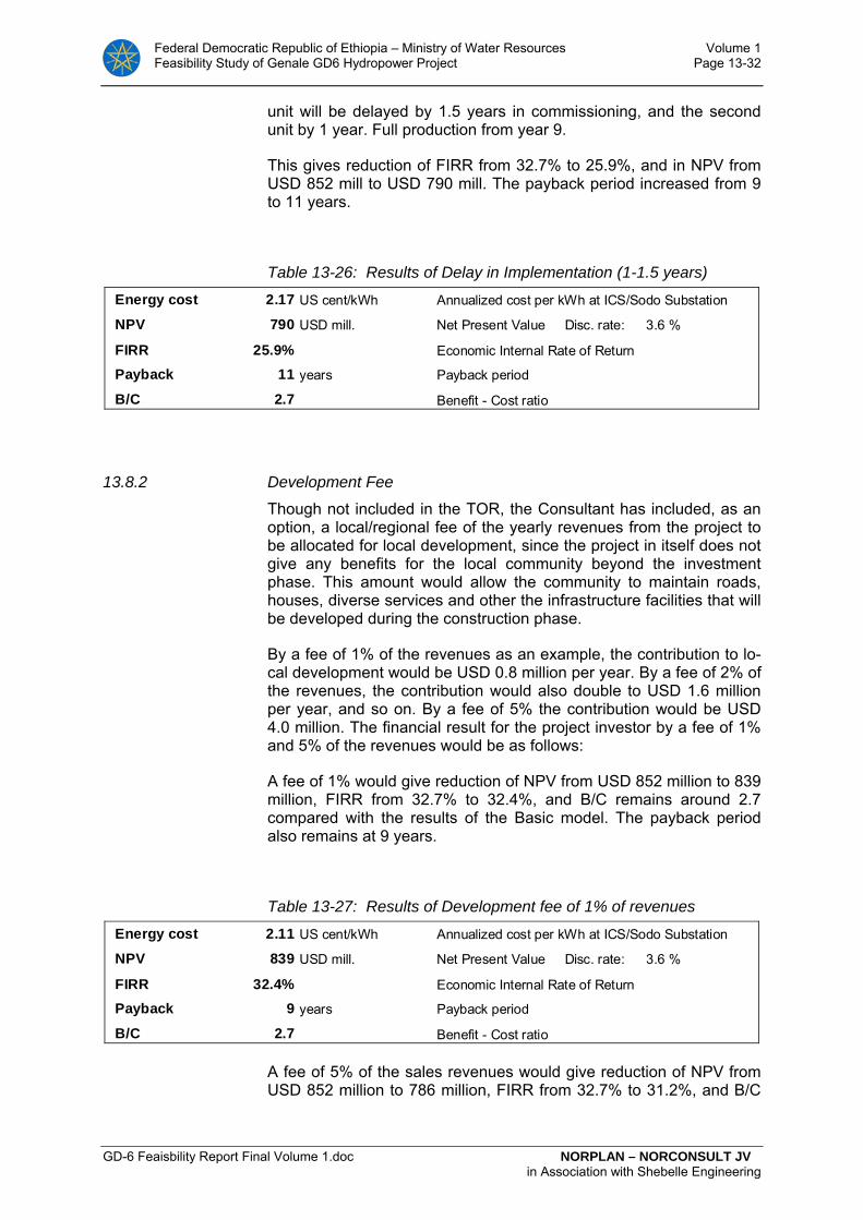
Federal Democratic Republic of Ethiopia – Ministry of Water Resources Volume 1 Feasibility Study of Genale GD6 Hydropower Project Page 13-32
GD-6 Feaisbility Report Final Volume 1.doc NORPLAN – NORCONSULT JV in Association with Shebelle Engineering
unit will be delayed by 1.5 years in commissioning, and the second unit by 1 year. Full production from year 9.
This gives reduction of FIRR from 32.7% to 25.9%, and in NPV from USD 852 mill to USD 790 mill. The payback period increased from 9 to 11 years.
Table 13-26: Results of Delay in Implementation (1-1.5 years)
Energy cost 2.17 US cent/kWh Annualized cost per kWh at ICS/Sodo Substation
NPV 790 USD mill. Net Present Value Disc. rate: 3.6 %
FIRR 25.9% Economic Internal Rate of Return
Payback 11 years Payback period
B/C 2.7 Benefit - Cost ratio
13.8.2 Development Fee
Though not included in the TOR, the Consultant has included, as an option, a local/regional fee of the yearly revenues from the project to be allocated for local development, since the project in itself does not give any benefits for the local community beyond the investment phase. This amount would allow the community to maintain roads, houses, diverse services and other the infrastructure facilities that will be developed during the construction phase.
By a fee of 1% of the revenues as an example, the contribution to lo-cal development would be USD 0.8 million per year. By a fee of 2% of the revenues, the contribution would also double to USD 1.6 million per year, and so on. By a fee of 5% the contribution would be USD 4.0 million. The financial result for the project investor by a fee of 1% and 5% of the revenues would be as follows:
A fee of 1% would give reduction of NPV from USD 852 million to 839 million, FIRR from 32.7% to 32.4%, and B/C remains around 2.7 compared with the results of the Basic model. The payback period also remains at 9 years.
Table 13-27: Results of Development fee of 1% of revenues
Energy cost 2.11 US cent/kWh Annualized cost per kWh at ICS/Sodo Substation
NPV 839 USD mill. Net Present Value Disc. rate: 3.6 %
FIRR 32.4% Economic Internal Rate of Return
Payback 9 years Payback period
B/C 2.7 Benefit - Cost ratio
A fee of 5% of the sales revenues would give reduction of NPV from USD 852 million to 786 million, FIRR from 32.7% to 31.2%, and B/C
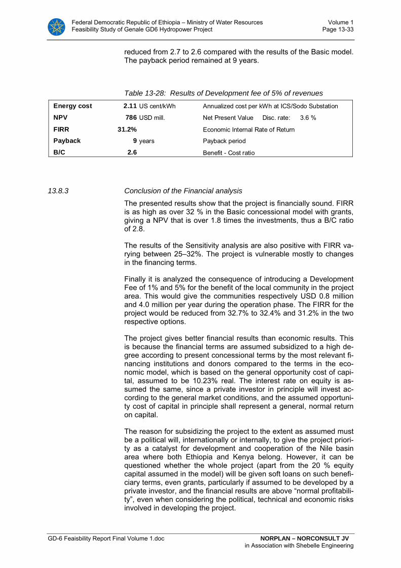
Federal Democratic Republic of Ethiopia – Ministry of Water Resources Volume 1 Feasibility Study of Genale GD6 Hydropower Project Page 13-33
GD-6 Feaisbility Report Final Volume 1.doc NORPLAN – NORCONSULT JV in Association with Shebelle Engineering
reduced from 2.7 to 2.6 compared with the results of the Basic model. The payback period remained at 9 years.
Table 13-28: Results of Development fee of 5% of revenues
Energy cost 2.11 US cent/kWh Annualized cost per kWh at ICS/Sodo Substation
NPV 786 USD mill. Net Present Value Disc. rate: 3.6 %
FIRR 31.2% Economic Internal Rate of Return
Payback 9 years Payback period
B/C 2.6 Benefit - Cost ratio
13.8.3 Conclusion of the Financial analysis
The presented results show that the project is financially sound. FIRR is as high as over 32 % in the Basic concessional model with grants, giving a NPV that is over 1.8 times the investments, thus a B/C ratio of 2.8.
The results of the Sensitivity analysis are also positive with FIRR va-rying between 25–32%. The project is vulnerable mostly to changes in the financing terms.
Finally it is analyzed the consequence of introducing a Development Fee of 1% and 5% for the benefit of the local community in the project area. This would give the communities respectively USD 0.8 million and 4.0 million per year during the operation phase. The FIRR for the project would be reduced from 32.7% to 32.4% and 31.2% in the two respective options.
The project gives better financial results than economic results. This is because the financial terms are assumed subsidized to a high de-gree according to present concessional terms by the most relevant fi-nancing institutions and donors compared to the terms in the eco-nomic model, which is based on the general opportunity cost of capi-tal, assumed to be 10.23% real. The interest rate on equity is as-sumed the same, since a private investor in principle will invest ac-cording to the general market conditions, and the assumed opportuni-ty cost of capital in principle shall represent a general, normal return on capital.
The reason for subsidizing the project to the extent as assumed must be a political will, internationally or internally, to give the project priori-ty as a catalyst for development and cooperation of the Nile basin area where both Ethiopia and Kenya belong. However, it can be questioned whether the whole project (apart from the 20 % equity capital assumed in the model) will be given soft loans on such benefi-ciary terms, even grants, particularly if assumed to be developed by a private investor, and the financial results are above “normal profitabili-ty”, even when considering the political, technical and economic risks involved in developing the project.
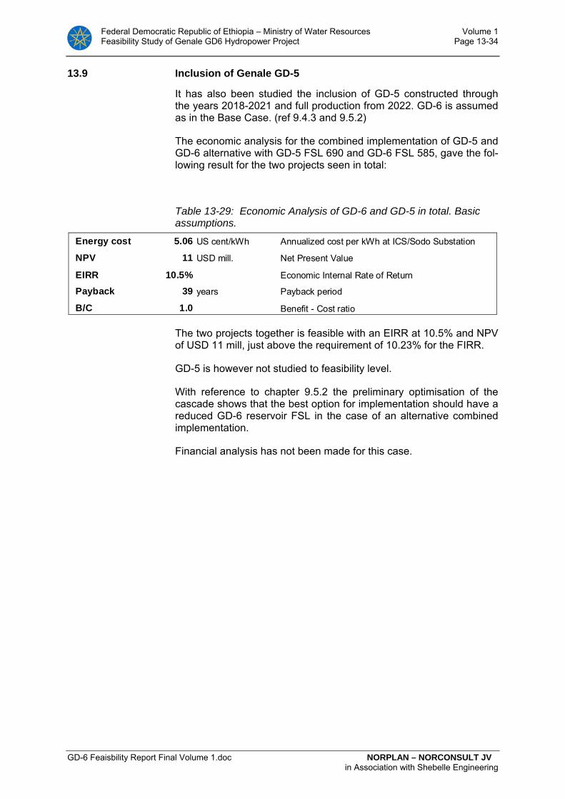
Federal Democratic Republic of Ethiopia – Ministry of Water Resources Volume 1 Feasibility Study of Genale GD6 Hydropower Project Page 13-34
GD-6 Feaisbility Report Final Volume 1.doc NORPLAN – NORCONSULT JV in Association with Shebelle Engineering
13.9 Inclusion of Genale GD-5
It has also been studied the inclusion of GD-5 constructed through the years 2018-2021 and full production from 2022. GD-6 is assumed as in the Base Case. (ref 9.4.3 and 9.5.2)
The economic analysis for the combined implementation of GD-5 and GD-6 alternative with GD-5 FSL 690 and GD-6 FSL 585, gave the fol-lowing result for the two projects seen in total:
Table 13-29: Economic Analysis of GD-6 and GD-5 in total. Basic assumptions.
Energy cost 5.06 US cent/kWh Annualized cost per kWh at ICS/Sodo Substation
NPV 11 USD mill. Net Present Value
EIRR 10.5% Economic Internal Rate of Return
Payback 39 years Payback period
B/C 1.0 Benefit - Cost ratio
The two projects together is feasible with an EIRR at 10.5% and NPV of USD 11 mill, just above the requirement of 10.23% for the FIRR.
GD-5 is however not studied to feasibility level.
With reference to chapter 9.5.2 the preliminary optimisation of the cascade shows that the best option for implementation should have a reduced GD-6 reservoir FSL in the case of an alternative combined implementation.
Financial analysis has not been made for this case.