GEN10-15KW SERIES · GEN10-15KW SERIES Laboratory Power Supplies: 10 ~ 15KW Features High Power...
12
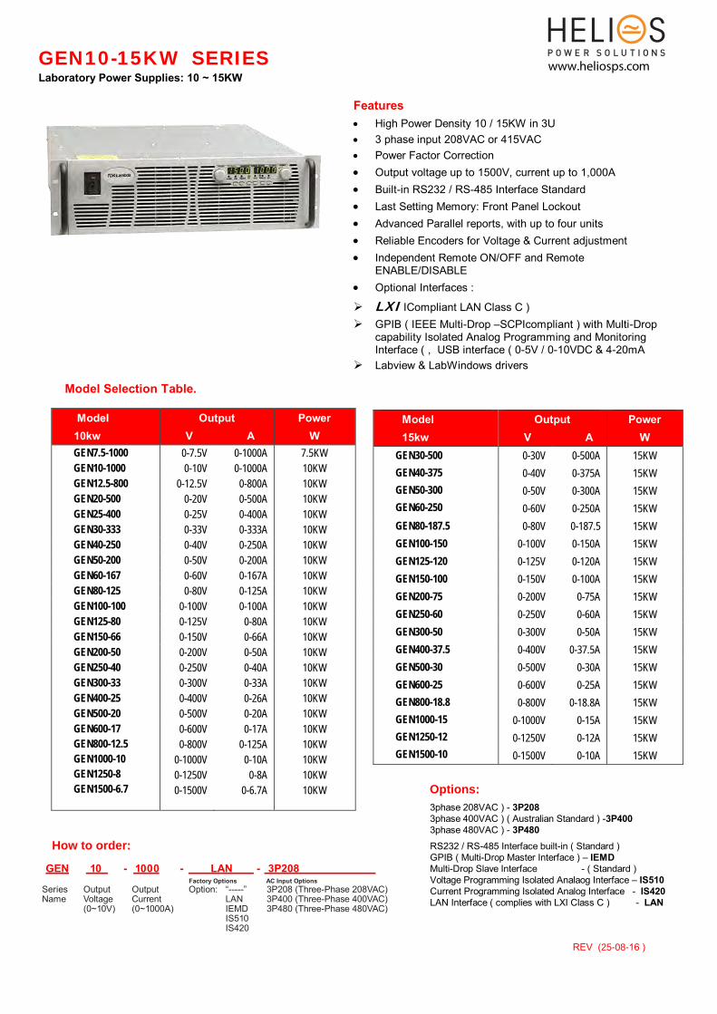
GEN10-15KW SERIES Laboratory Power Supplies: 10 ~ 15KW Features High Power Density 10 / 15KW in 3U 3 phase input 208VAC or 415VAC Power Factor Correction Output voltage up to 1500V, current up to 1,000A Built-in RS232 / RS-485 Interface Standard Last Setting Memory: Front Panel Lockout Advanced Parallel reports, with up to four units Reliable Encoders for Voltage & Current adjustment Independent Remote ON/OFF and Remote ENABLE/DISABLE Optional Interfaces : LXI ICompliant LAN Class C ) GPIB ( IEEE Multi-Drop –SCPIcompliant ) with Multi-Drop capability Isolated Analog Programming and Monitoring Interface ( , USB interface ( 0-5V / 0-10VDC & 4-20mA Labview & LabWindows drivers Model Selection Table. ModeI 10kw Output V A Power W GEN7.5-1000 0-7.5V 0-1000A 7.5KW GEN10-1000 0-10V 0-1000A 10KW GEN12.5-800 0-12.5V 0-800A 10KW GEN20-500 0-20V 0-500A 10KW GEN25-400 0-25V 0-400A 10KW GEN30-333 0-33V 0-333A 10KW GEN40-250 0-40V 0-250A 10KW GEN50-200 0-50V 0-200A 10KW GEN60-167 0-60V 0-167A 10KW GEN80-125 0-80V 0-125A 10KW GEN100-100 0-100V 0-100A 10KW GEN125-80 0-125V 0-80A 10KW GEN150-66 0-150V 0-66A 10KW GEN200-50 0-200V 0-50A 10KW GEN250-40 0-250V 0-40A 10KW GEN300-33 0-300V 0-33A 10KW GEN400-25 0-400V 0-26A 10KW GEN500-20 0-500V 0-20A 10KW GEN600-17 GEN800-12.5 GEN1000-10 GEN1250-8 GEN1500-6.7 0-600V 0-800V 0-1000V 0-1250V 0-1500V 0-17A 0-125A 0-10A 0-8A 0-6.7A 10KW 10KW 10KW 10KW 10KW Model 15kw Output V A Power W GEN30-500 GEN40-375 GEN50-300 GEN60-250 0-30V 0-40V 0-50V 0-60V 0-500A 0-375A 0-300A 0-250A 15KW 15KW 15KW 15KW GEN80-187.5 0-80V 0-187.5 15KW GEN100-150 0-100V 0-150A 15KW GEN125-120 0-125V 0-120A 15KW GEN150-100 0-150V 0-100A 15KW GEN200-75 0-200V 0-75A 15KW GEN250-60 0-250V 0-60A 15KW GEN300-50 0-300V 0-50A 15KW GEN400-37.5 0-400V 0-37.5A 15KW GEN500-30 0-500V 0-30A 15KW GEN600-25 GEN800-18.8 GEN1000-15 GEN1250-12 GEN1500-10 0-600V 0-800V 0-1000V 0-1250V 0-1500V 0-25A 0-18.8A 0-15A 0-12A 0-10A 15KW 15KW 15KW 15KW 15KW 3phase 208VAC ) - 3P208 3phase 400VAC ) ( Australian Standard ) -3P400 3phase 480VAC ) - 3P480 RS232 / RS-485 Interface built-in ( Standard ) GPIB ( Multi-Drop Master Interface ) – IEMD Multi-Drop Slave Interface - ( Standard ) Voltage Programming Isolated Analaog Interface – IS510 Current Programming Isolated Analog Interface - IS420 LAN Interface ( complies with LXI Class C ) - LAN Series Output Output Option: “-----” 3P208 (Three-Phase 208VAC) Name Voltage Current LAN 3P400 (Three-Phase 400VAC) (0~10V) (0~1000A) IEMD 3P480 (Three-Phase 480VAC) IS510 IS420 GEN 10 - 1000 - LAN - 3P208 Factory Options AC Input Options REV ( 16 ) www.heliosps.com
Transcript of GEN10-15KW SERIES · GEN10-15KW SERIES Laboratory Power Supplies: 10 ~ 15KW Features High Power...
GEN10-15KW SERIES
Laboratory Power Supplies: 10 ~ 15KW
Features High Power Density 10 / 15KW in 3U 3 phase input 208VAC or 415VAC Power Factor Correction Output voltage up to 1500V, current up to 1,000A
Built-in RS232 / RS-485 Interface Standard
Last Setting Memory: Front Panel Lockout Advanced Parallel reports, with up to four units
Reliable Encoders for Voltage & Current adjustment Independent Remote ON/OFF and Remote
ENABLE/DISABLE
Optional Interfaces :
LXI ICompliant LAN Class C ) GPIB ( IEEE Multi-Drop –SCPIcompliant ) with Multi-Drop
capability Isolated Analog Programming and Monitoring Interface ( , USB interface ( 0-5V / 0-10VDC & 4-20mA
Labview & LabWindows drivers
Model Selection Table.
ModeI 10kw
Output V A
Power W
GEN7.5-1000 0-7.5V 0-1000A 7.5KW
GEN10-1000 0-10V 0-1000A 10KW
GEN12.5-800 0-12.5V 0-800A 10KW
GEN20-500 0-20V 0-500A 10KW
GEN25-400 0-25V 0-400A 10KW
GEN30-333 0-33V 0-333A 10KW
GEN40-250 0-40V 0-250A 10KW
GEN50-200 0-50V 0-200A 10KW
GEN60-167 0-60V 0-167A 10KW
GEN80-125 0-80V 0-125A 10KW
GEN100-100 0-100V 0-100A 10KW
GEN125-80 0-125V 0-80A 10KW
GEN150-66 0-150V 0-66A 10KW
GEN200-50 0-200V 0-50A 10KW
GEN250-40 0-250V 0-40A 10KW
GEN300-33 0-300V 0-33A 10KW
GEN400-25 0-400V 0-26A 10KW
GEN500-20 0-500V 0-20A 10KW
GEN600-17
GEN800-12.5
GEN1000-10
GEN1250-8
GEN1500-6.7
0-600V
0-800V
0-1000V
0-1250V
0-1500V
0-17A
0-125A
0-10A
0-8A
0-6.7A
10KW
10KW
10KW
10KW
10KW
Model 15kw
Output V A
Power W
GEN30-500
GEN40-375
GEN50-300
GEN60-250
0-30V
0-40V
0-50V
0-60V
0-500A
0-375A
0-300A
0-250A
15KW
15KW
15KW
15KW
GEN80-187.5 0-80V 0-187.5 15KW
GEN100-150 0-100V 0-150A 15KW
GEN125-120 0-125V 0-120A 15KW
GEN150-100 0-150V 0-100A 15KW
GEN200-75 0-200V 0-75A 15KW
GEN250-60 0-250V 0-60A 15KW
GEN300-50 0-300V 0-50A 15KW
GEN400-37.5 0-400V 0-37.5A 15KW
GEN500-30 0-500V 0-30A 15KW
GEN600-25
GEN800-18.8
GEN1000-15
GEN1250-12
GEN1500-10
0-600V
0-800V
0-1000V
0-1250V
0-1500V
0-25A
0-18.8A
0-15A
0-12A
0-10A
15KW
15KW
15KW
15KW
15KW
3phase 208VAC ) - 3P208 3phase 400VAC ) ( Australian Standard ) -3P400 3phase 480VAC ) - 3P480
RS232 / RS-485 Interface built-in ( Standard ) GPIB ( Multi-Drop Master Interface ) – IEMD Multi-Drop Slave Interface - ( Standard ) Voltage Programming Isolated Analaog Interface – IS510
Current Programming Isolated Analog Interface - IS420 LAN Interface ( complies with LXI Class C ) - LAN
Options:
Series Output Output Option: “-----” 3P208 (Three-Phase 208VAC) Name Voltage Current LAN 3P400 (Three-Phase 400VAC) (0~10V) (0~1000A) IEMD 3P480 (Three-Phase 480VAC) IS510 IS420
GEN 10 - 1000 - LAN - 3P208 Factory Options AC Input Options
How to order:
REV (25-08-16 )
www.heliosps.com
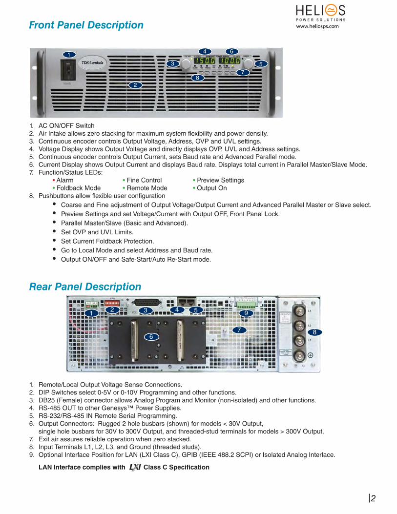
Front Panel Description
1. AC ON/OFF Switch2. Air Intake allows zero stacking for maximum system fl exibility and power density.3. Continuous encoder controls Output Voltage, Address, OVP and UVL settings.4. Voltage Display shows Output Voltage and directly displays OVP, UVL and Address settings.5. Continuous encoder controls Output Current, sets Baud rate and Advanced Parallel mode.6. Current Display shows Output Current and displays Baud rate. Displays total current in Parallel Master/Slave Mode.7. Function/Status LEDs:
• Alarm • Fine Control • Preview Settings• Foldback Mode • Remote Mode • Output On
8. Pushbuttons allow fl exible user confi guration• Coarse and Fine adjustment of Output Voltage/Output Current and Advanced Parallel Master or Slave select.• Preview Settings and set Voltage/Current with Output OFF, Front Panel Lock.• Parallel Master/Slave (Basic and Advanced). • Set OVP and UVL Limits.• Set Current Foldback Protection.• Go to Local Mode and select Address and Baud rate.• Output ON/OFF and Safe-Start/Auto Re-Start mode.
1
2
3 5
8
4 6
7
1. Remote/Local Output Voltage Sense Connections.2. DIP Switches select 0-5V or 0-10V Programming and other functions.3. DB25 (Female) connector allows Analog Program and Monitor (non-isolated) and other functions.4. RS-485 OUT to other Genesys™ Power Supplies.5. RS-232/RS-485 IN Remote Serial Programming.6. Output Connectors: Rugged 2 hole busbars (shown) for models < 30V Output, single hole busbars for 30V to 300V Output, and threaded-stud terminals for models > 300V Output.7. Exit air assures reliable operation when zero stacked.8. Input Terminals L1, L2, L3, and Ground (threaded studs).9. Optional Interface Position for LAN (LXI Class C), GPIB (IEEE 488.2 SCPI) or Isolated Analog Interface.
LAN Interface complies with Class C Specifi cation
Rear Panel Description
1 2 3 5
8
94
67
2
www.heliosps.com
GenesysTM 3U 10/15kW
GenesysTM 3U 10kW Specifi cations10kW
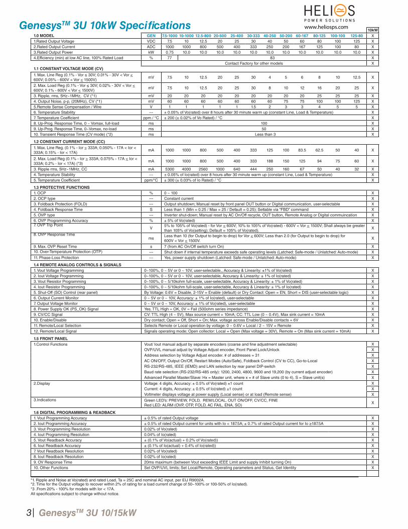
1.0 MODEL GEN 7.5-1000 10-1000 12.5-800 20-500 25-400 30-333 40-250 50-200 60-167 80-125 100-100 125-80 X1.Rated Output Voltage VDC 7.5 10 12.5 20 25 30 40 50 60 80 100 125 X2.Rated Output Current ADC 1000 1000 800 500 400 333 250 200 167 125 100 80 X3.Rated Output Power kW 0.75 10.0 10.0 10.0 10.0 10.0 10.0 10.0 10.0 10.0 10.0 10.0 X4.Efficiency (min) at low AC line, 100% Rated Load % 77 83 X
1.1 CONSTANT VOLTAGE MODE (CV)
Contact Factory for other models X
1. Max. Line Reg (0.1% - Vor ≤ 30V; 0.01% - 30V < Vor < 600V; 0.05% - 600V < Vor < 1500V)
mV 7.5 10 12.5 20 25 30 4 5 6 8 10 12.5 X
2. Max. Load Reg (0.1% - Vor ≤ 30V; 0.02% - 30V < Vor < 600V; 0.1% - 600V < Vor < 1500V)
mV 7.5 10 12.5 20 25 30 8 10 12 16 20 25 X
3. Ripple, rms, 5Hz~1MHz, CV (*1) mV 20 20 20 20 20 20 20 20 20 25 25 25 X4. Output Noise, p-p, (20MHz), CV (*1) mV 60 60 60 60 60 60 60 75 75 100 100 125 X5.Remote Sense Compensation / Wire V 1 1 1 1 1 1.5 2 3 3 4 5 5 X6. Temperature Stability --- ± 0.05% of Vo(rated) over 8 hours after 30 minute warm up (constant Line, Load & Temperature) X7. Temperature Coefficient ppm / °C ± 200 (± 0.02% of Vo Rated) / °C X8. Up-Prog. Response Time, 0 ~ Vomax, full-load ms 100 X9. Up-Prog. Response Time, 0~Vomax, no-load ms 50 X10. Transient Response Time (CV mode) (*2) ms Less than 3 X
1.2 CONSTANT CURRENT MODE (CC)
1. Max. Line Reg. (0.1% - Ior > 333A; 0.050% - 17A < Ior < 333A; 0.15% - Ior < 17A)
mA 1000 1000 800 500 400 333 125 100 83.5 62.5 50 40 X
2. Max. Load Reg (0.1% - Ior > 333A; 0.075% - 17A < Ior < 333A; 0.2% - Ior < 17A) (*3)
mA 1000 1000 800 500 400 333 188 150 125 94 75 60 X
3. Ripple rms, 5Hz~1MHz, CC mA 5300 4000 2560 1000 640 444 250 160 67 50 40 32 X4. Temperature Stability --- ± 0.05% of Io(rated) over 8 hours after 30 minute warm up (constant Line, Load & Temperature) X5. Temperature Coefficient ppm/°C ± 300 (± 0.03% of Io Rated) / °C X
1.3 PROTECTIVE FUNCTIONS
1. OCP % 0 ~ 100 X2. OCP type --- Constant current X3. Foldback Protection (FOLD) --- Output shutdown; Manual reset by front panel OUT button or Digital communication, user-selectable X4. Foldback Response Time S Less than 1 (Min = 0.25 / Max = 25 / Default = 0.25); Settable via “FBD” command X5. OVP type --- Inverter shut-down; Manual reset by AC On/Off recycle, OUT button, Remote Analog or Digital commuincation X6. OVP Programming Accuracy % ± 5% of Vo(rated) X7. OVP Trip Point
V5% to 105% of Vo(rated) - for Vor < 600V; 10% to 105% of Vo(rated) - 600V < Vor < 1500V; Shall always be greater than 105% of Vo(setting); Default = 105% of Vo(rated).
X
8. OVP Response Timems
Less than 10 (for Output to begin to drop) for Vor < 600V; Less than 2.0 (for Output to begin to drop) for 600V < Vor < 1500V.
X
9. Max. OVP Reset Time s 7 (from AC On/Off switch turn On) X10. Over-Temperature Protection (OTP) --- Shut down if internal temperature exceeds safe operating levels (Latched: Safe-mode / Unlatched: Auto-mode) X11. Phase-Loss Protection --- Yes, power supply shutdown (Latched: Safe-mode / Unlatched: Auto-mode) X
1.4 REMOTE ANALOG CONTROLS & SIGNALS
1. Vout Voltage Programming 0~100%, 0 ~ 5V or 0 ~ 10V, user-selectable., Accuracy & Linearity: ±1% of Vo(rated) X2. Iout Voltage Programming 0~100%, 0 ~ 5V or 0 ~ 10V, user-selectable, Accuracy & Linearity: ± 1% of Io(rated) X3. Vout Resistor Programming 0~100%, 0 ~ 5/10kohm full-scale, user-selectable, Accuracy & Linearity: ± 1% of Vo(rated) X4. Iout Resistor Programming 0~100%, 0 ~ 5/10kohm full-scale, user-selectable, Accuracy & Linearity: ± 1% of Io(rated) X5. Shut-Off (SO) Control (rear panel) By Voltage: 0.6V = Disable, 2-15V = Enable (default) or Dry Contact: Open = EN, Short = DIS (user-selectable logic) X6. Output Current Monitor 0 ~ 5V or 0 ~ 10V, Accuracy: ± 1% of Io(rated), user-selectable X7. Output Voltage Monitor 0 ~ 5V or 0 ~ 10V, Accuracy: ± 1% of Vo(rated), user-selectable X8. Power Supply OK (PS_OK) Signal Yes. TTL High = OK, 0V = Fail (500ohm series impedance) X9. CV/CC Signal CV: TTL High (4 ~ 5V), Max source current = 10mA; CC: TTL Low (0 ~ 0.4V), Max sink current = 10mA X10. Enable/Disable Dry contact; Open = Off, Short = On; Max. voltage across Enable/Disable contacts = 6V X11. Remote/Local Selection Selects Remote or Local operation by voltage: 0 ~ 0.6V = Local / 2 ~ 15V = Remote X12. Remote/Local Signal Signals operating mode; Open collector: Local = Open (Max voltage = 30V), Remote = On (Max sink current = 10mA) X
1.5 FRONT PANEL
1.Control Functions Vout/ Iout manual adjust by separate encoders (coarse and fi ne adjustment selectable) XOVP/UVL manual adjust by Voltage Adjust encoder, Front Panel Lock/Unlock XAddress selection by Voltage Adjust encoder. # of addresses = 31 XAC ON/OFF, Output On/Off, Restart Modes (Auto/Safe), Foldback Control (CV to CC), Go-to-Local XRS-232/RS-485, IEEE (IEMD) and LAN selection by rear panel DIP-switch XBaud rate selection (RS-232/RS-485 only): 1200, 2400, 4800, 9600 and 19,200 (by current adjust encoder) XAdvanced Parallel Master/Slave: Hx = Master unit, where x = # of Slave units (0 to 4), S = Slave unit(s) X
2.Display Voltage: 4 digits, Accuracy: ± 0.5% of Vo(rated) ±1 count XCurrent: 4 digits, Accuracy: ± 0.5% of Io(rated) ±1 count XVoltmeter displays voltage at power supply (Local sense) or at load (Remote sense) X
3.Indications Green LED’s: PREVIEW, FOLD, REM/LOCAL, OUT ON/OFF, CV/CC, FINERed LED: ALRM (OVP, OTP, FOLD, AC FAIL, ENA, SO)
X
1.6 DIGITAL PROGRAMMING & READBACK
1. Vout Programming Accuracy ± 0.5% of rated Output voltage X2. Iout Programming Accuracy ± 0.5% of rated Output current for units with Io < 187.5A; ± 0.7% of rated Output current for Io ≥187.5A X3. Vout Programming Resolution 0.02% of Vo(rated) X4. Iout Programming Resolution 0.04% of Io(rated) X5. Vout Readback Accuracy ± (0.1% of Vo(actual) + 0.2% of Vo(rated)) X6. Iout Readback Accuracy ± (0.1% of Io(actual) + 0.4% of Io(rated)) X7. Vout Readback Resolution 0.02% of Vo(rated) X8. Iout Readback Resolution 0.02% of Io(rated) X9. OV Response Time 20ms maximum (between Vout exceeding IEEE Limit and supply Inhibit turning On) X10. Other Functions Set OVP/UVL limits; Set Local/Remote, Operating parameters and Status, Get Identity X
*1. Ripple and Noise at Vo(rated) and rated Load, Ta = 25C and nominal AC input, per EIJ R9002A.*2. Time for the Output voltage to recover within 2% of rating for a load current change of 50~100% or 100-50% of Io(rated).*3 .From 20% - 100% for models with Ior < 17A.All specifi cations subject to change without notice.
3
www.heliosps.com
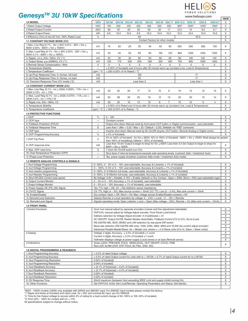
GenesysTM 3U 10kW Specifi cations10kW
1.0 MODEL GEN 150-66 200-50 250-40 300-33 400-25 500-20 600-17 800-12.5 1000-10 1250-8 1500-6.7 X
1.Rated Output Voltage VDC 150 200 250 300 400 500 600 800* 1000* 1250* 1500* X
2.Rated Output Current ADC 66 50 40 33 25 20 17 12.5 10 8.0 6.7 X
3.Rated Output Power kW 9.9 10.0 10.0 9.9 10.0 10.0 10.2 10.0 10.0 10.0 10.0 X4.Efficiency (min) at low AC line, 100% Rated Load % 83 93.5 X
1.1 CONSTANT VOLTAGE MODE (CV) Contact Factory for other models X
1. Max. Line Reg (0.1% - Vor ≤ 30V; 0.01% - 30V < Vor < 600V; 0.05% - 600V < Vor < 1500V)
mV 15 20 25 30 40 50 60 400 500 625 750 X
2. Max. Load Reg (0.1% - Vor ≤ 30V; 0.02% - 30V < Vor < 600V; 0.1% - 600V < Vor < 1500V)
mV 30 40 50 60 80 100 120 800 1000 1250 1500 X
3. Ripple, r.m.s, 5Hz~1MHz, CV (*1) mV 25 35 35 60 60 60 60 80 100 120 140 X4. Output Noise, p-p (20MHz), CV (*1) mV 150 175 200 200 300 350 350 700 800 1000 1400 X5.Remote Sense Compensation / Wire V 5 5 5 5 5 5 5 5 5 5 5 X6. Temperature Stability --- ± 0.05% of Vo(rated) over 8 hours after 30 minute warm up (constant Line, Load & Temperature) X7. Temperature Coefficient ppm / °C ± 200 (0.02% of Vo Rated) / °C X8. Up-Prog. Response Time, 0~Vomax, full-load mS 100 17 X9. Up-Prog. Response Time, 0~Vomax, no load mS 50 17 X10. Transient Response Time (CV mode) (*2) mS Less than 3 Less than 1 X
1.2 CONSTANT CURRENT MODE (CC)
1. Max. Line Reg. (0.1% - Ior > 333A; 0.050% - 17A < Ior < 333A; 0.15% - Ior < 17A)
mA 33 25 20 17 13 10 9 19 15 12 10 X
2. Max. Load Reg (0.1% - Ior > 333A; 0.075% - 17A < Ior < 333A; 0.2% - Ior < 17A) (*3)
mA 50 38 30 25 19 15 13 25 20 15 14 X
3. Ripple rms, 5Hz~1MHz, CC mA 26 20 16 13 10 8 7 15 10 6 4 X4. Temperature Stability --- ± 0.05% of Io Rated over 8 hours after 30 minute warm up (constant Line, Load & Temperature) X5. Temperature Coefficient ppm / °C ± 300 (0.03% of Io Rated) / °C X
1.3 PROTECTIVE FUNCTIONS
1. OCP % 0 ~ 100 X2. OCP type --- Constant current X3. Foldback Protection (FOLD) --- Output shut down; Manual reset by front panel OUT button or Digital communication, user-selectable X4. Foldback Response Time S Less than 1 (Min = 0.25 / Max = 25 / Default = 0.25); Settable via “FBD” command X5. OVP type --- Inverter shut-down; Manual reset by AC On/Off recycle, OUT button, Remote Analog or Digital comm. X6. OVP Programming Accuracy % ± 5% of Vo(rated) X
7. OVP Trip Point V5% to 105% of Vo(rated) - for Vor < 600V; 10% to 105% of Vo(rated) - 600V < Vor < 1500V; Shall always be greater than 105% of Vo(setting); Default = 105% of Vo(rated).
8. OVP response time mSLess than 10 (for Output to begin to drop) for Vor < 600V; Less than 2.0 (for Output to begin to drop) for 600V < Vor < 1500V.
X
9. Max. OVP reset time S 7 (from AC On/Off switch turn On) X10. Over-Temperature Protection (OTP) --- Shut down if internal temperature exceeds safe operating levels. (Latched: Safe / Unlatched: Auto) X11. Phase-Loss Protection --- Yes, power supply shutdown (Latched: Safe-mode / Unlatched: Auto-mode) X
1.4 REMOTE ANALOG CONTROLS & SIGNALS
1. Vout Voltage Programming 0~100%, 0 ~ 5V or 0 ~ 10V, user-selectable, Accuracy & Linearity: ± 1% of Vo(rated) X2. Iout Voltage Programming 0 ~ 100%, 0~5V or 0 ~ 10V, user-selectable. Accuracy & Linearity ± 1% of Io(rated) X3. Vout resistor programming 0~100%, 0~5/10kohm full-scale, user-selectable. Accuracy & Linearity ± 1% of Vo(rated) X4. Iout Resistor Programming 0~100%, 0~5/10kohm full-scale, user-selectable. Accuracy & Linearity ± 1% of Io(rated) X5. Shut-Off (SO) Control (rear panel) By Voltage: 0.6V = Disable, 2-15V = Enable (default) or Dry Contact : Open = ENA, Short = DIS (user-selectable logic) X6. Output Current Monitor 0 ~ 5V or 0 ~ 10V, Accuracy: ± 1% of Io(rated), user-selectable X7. Output Voltage Monitor 0 ~ 5V or 0 ~ 10V, Accuracy: ± 1% of Vo(rated), user-selectable X8. Power Supply OK (PS_OK) Signal Yes. TTL high = OK, 0V = Fail (500ohm series impedance) X9. CV/CC Signal CV: TTL High (4 ~ 5V), Max source current = 10mA; CC: TTL Low (0 ~ 0.4V), Max sink current = 10mA X10. Enable/Disable Dry contact; Open = Off, Short = On; Max. voltage across Enable/Disable contacts = 6V X11. Remote/Local Selection Selects Remote or Local operation by voltage: 0 ~ 0.6V = Local / 2 ~ 15V = Remote X12. Remote/Local Signal Signals operating mode; Open collector: Local = Open (Max voltage = 30V), Remote = On (Max sink current = 10mA) X
1.5 FRONT PANEL
1.Control Functions Vout/ Iout manual adjust by separate encoders (coarse and fi ne adjustment selectable) XOVP/UVL manual adjust by Voltage Adjust encoder, Front Panel Lock/Unlock XAddress selection by Voltage Adjust encoder. # of addresses = 31 XAC ON/OFF, Output On/Off, Restart Modes (Auto/Safe), Foldback Control (CV to CC), Go-to-Local XRS-232/RS-485, IEEE (IEMD) and LAN selection by rear-panel DIP-switch XBaud rate selection (RS-232/RS-485 only): 1200, 2400, 4800, 9600 and 19,200 (by current adjust encoder) XAdvanced Parallel Master/Slave: Hx = Master unit, where x = # of Slave units (0 to 4), Slave = Slave unit(s) X
2.Display Voltage: 4 digits, Accuracy: ± 0.5% of Vo(rated) ±1 count XCurrent: 4 digits, Accuracy: ± 0.5% of Io(rated) ±1 count XVoltmeter displays voltage at power supply (Local sense) or at load (Remote sense) X
3.Indications Green LED’s: PREVIEW, FOLD, REM/LOCAL, OUT ON/OFF, CV/CC, FINERed LED: ALRM (OVP, OTP, FOLD, AC FAIL, ENA, SO)
X
1.6 DIGITAL PROGRAMMING & READBACK
1. Vout Programming Accuracy ± 0.5% of rated Output voltage X2. Iout Programming Accuracy ± 0.5% of rated Output current for units with Io < 187.5A; ± 0.7% of rated Output current for Io ≥187.5A X3. Vout Programming Resolution 0.02% of Vo(rated) X4. Iout Programming Resolution 0.04% of Io(rated) X5. Vout Readback Accuracy ± (0.1% of Vo(actual) + 0.2% of Vo(rated)) X6. Iout Readback Accuracy ± (0.1% of Vo(actual) + 0.4% of Vo(rated)) X7. Vout Readback Resolution 0.02% of Vo(rated) X8. Iout Readback Resolution 0.02% of Io(rated) X9. OV Response Time 20mS maximum (between Vout exceeding IEEE Limit and supply Inhibit turning On) X10. Other Functions Set OVP/UVL limits; Set Local/Remote, Operating Parameters and Status; Get Identity X
*800V - 1500V models (10kW) only available with 400VA and 480VAC input. For 208VAC Input models please contact the factory.*1. Ripple and Noise at Vo(rated) and rated Load, Ta = 25C and nominal AC input. per EIJ R9002A*2. Time for the Output voltage to recover within 2% of rating for a load current change of 50~100% or 100~50% of Io(rated).*3. From 20% - 100% for models with Ior < 17A.All specifi cations subject to change without notice.
4
www.heliosps.com
GenesysTM 3U 10/15kW
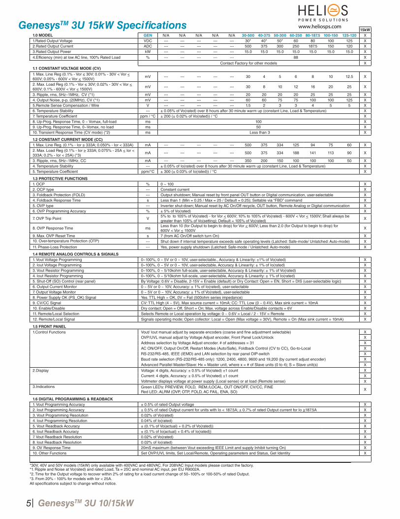
GenesysTM 3U 15kW Specifi cations15kW
1.0 MODEL GEN N/A N/A N/A N/A N/A 30-500 40-375 50-300 60-250 80-187.5 100-150 125-120 X1.Rated Output Voltage VDC --- --- --- --- --- 30* 40* 50* 60 80 100 125 X2.Rated Output Current ADC --- --- --- --- --- 500 375 300 250 187.5 150 120 X3.Rated Output Power kW --- --- --- --- --- 15.0 15.0 15.0 15.0 15.0 15.0 15.0 X
4.Efficiency (min) at low AC line, 100% Rated Load % --- --- --- --- --- 88 X
1.1 CONSTANT VOLTAGE MODE (CV)
Contact Factory for other models X
1. Max. Line Reg (0.1% - Vor ≤ 30V; 0.01% - 30V < Vor < 600V; 0.05% - 600V < Vor < 1500V)
mV --- --- --- --- --- 30 4 5 6 8 10 12.5 X
2. Max. Load Reg (0.1% - Vor ≤ 30V; 0.02% - 30V < Vor < 600V; 0.1% - 600V < Vor < 1500V)
mV --- --- --- --- --- 30 8 10 12 16 20 25 X
3. Ripple, rms, 5Hz~1MHz, CV (*1) mV --- --- --- --- --- 20 20 20 20 25 25 25 X4. Output Noise, p-p, (20MHz), CV (*1) mV --- --- --- --- --- 60 60 75 75 100 100 125 X5.Remote Sense Compensation / Wire V --- --- --- --- --- 1.5 2 3 3 4 5 5 X6. Temperature Stability --- ± 0.05% of Vo(rated) over 8 hours after 30 minute warm up (constant Line, Load & Temperature) X7. Temperature Coefficient ppm / °C ± 200 (± 0.02% of Vo(rated)) / °C X8. Up-Prog. Response Time, 0 ~ Vomax, full-load ms 100 X9. Up-Prog. Response Time, 0~Vomax, no load ms 50 X10. Transient Response Time (CV mode) (*2) ms Less than 3 X
1.2 CONSTANT CURRENT MODE (CC)
1. Max. Line Reg. (0.1% - Ior ≥ 333A; 0.050% - Ior < 333A) mA --- --- --- --- --- 500 375 334 125 94 75 60 X2. Max. Load Reg (0.1% - Ior ≥ 333A; 0.075% - 25A < Ior < 333A; 0.2% - Ior < 25A) (*3)
mA --- --- --- --- --- 500 375 334 188 141 113 90 X
3. Ripple, rms, 5Hz~1MHz, CC mA --- --- --- --- --- 350 200 150 100 100 100 50 X4. Temperature Stability --- ± 0.05% of Io(rated) over 8 hours after 30 minute warm up (constant Line, Load & Temperature) X5. Temperature Coefficient ppm/°C ± 300 (± 0.03% of Io(rated)) / °C X
1.3 PROTECTIVE FUNCTIONS
1. OCP % 0 ~ 100 X2. OCP type --- Constant current X3. Foldback Protection (FOLD) --- Output shutdown; Manual reset by front panel OUT button or DIgital communication, user-selectable X4. Foldback Response Time s Less than 1 (Min = 0.25 / Max = 25 / Default = 0.25); Settable via “FBD” command X5. OVP type --- Inverter shut-down; Manual reset by AC On/Off recycle, OUT button, Remote Analog or Digital communication X6. OVP Programming Accuracy % ± 5% of Vo(rated) X
7. OVP Trip Point V5% to to 105% of Vo(rated) - for Vor < 600V; 10% to 105% of Vo(rated) - 600V < Vor < 1500V; Shall always be greater than 105% of Vo(setting); Default = 105% of Vo(rated)
X
8. OVP Response Time msLess than 10 (for Output to begin to drop) for Vor < 600V; Less than 2.0 (for Output to begin to drop) for 600V < Vor < 1500V
X
9. Max. OVP Reset Time s 7 (from AC On/Off switch turn On) X10. Over-temperature Protection (OTP) --- Shut down if internal temperature exceeds safe operating levels (Latched: Safe-mode/ Unlatched: Auto-mode) X11. Phase-Loss Protection --- Yes, power supply shutdown (Latched: Safe-mode / Unlatched: Auto-mode) X
1.4 REMOTE ANALOG CONTROLS & SIGNALS
1. Vout Voltage Programming 0~100%, 0 ~ 5V or 0 ~ 10V, user-selectable., Accuracy & Linearity: ±1% of Vo(rated) X2. Iout Voltage Programming 0~100%, 0 ~ 5V or 0 ~ 10V, user-selectable, Accuracy & Linearity: ± 1% of Io(rated) X3. Vout Resistor Programming 0~100%, 0 ~ 5/10kohm full-scale, user-selectable, Accuracy & Linearity: ± 1% of Vo(rated) X4. Iout Resistor Programming 0~100%, 0 ~ 5/10kohm full-scale, user-selectable, Accuracy & Linearity: ± 1% of Io(rated) X5. Shut-Off (SO) Control (rear panel) By Voltage: 0.6V = Disable, 2-15V = Enable (default) or Dry Contact: Open = EN, Short = DIS (user-selectable logic) X6. Output Current Monitor 0 ~ 5V or 0 ~ 10V, Accuracy: ± 1% of Io(rated), user-selectable X7. Output Voltage Monitor 0 ~ 5V or 0 ~ 10V, Accuracy: ± 1% of Vo(rated), user-selectable X8. Power Supply OK (PS_OK) Signal Yes. TTL High = OK, 0V = Fail (500ohm series impedance) X9. CV/CC Signal CV: TTL High (4 ~ 5V), Max source current = 10mA; CC: TTL Low (0 ~ 0.4V), Max sink current = 10mA X10. Enable/Disable Dry contact; Open = Off, Short = On; Max. voltage across Enable/Disable contacts = 6V X11. Remote/Local Selection Selects Remote or Local operation by voltage: 0 ~ 0.6V = Local / 2 - 15V = Remote X12. Remote/Local Signal Signals operating mode; Open collector: Local = Open (Max voltage = 30V), Remote = On (Max sink current = 10mA) X
1.5 FRONT PANEL
1.Control Functions Vout/ Iout manual adjust by separate encoders (coarse and fi ne adjustment selectable) XOVP/UVL manual adjust by Voltage Adjust encoder, Front Panel Lock/Unlock XAddress selection by Voltage Adjust encoder. # of addresses = 31 XAC ON/OFF, Output On/Off, Restart Modes (Auto/Safe), Foldback Control (CV to CC), Go-to-Local XRS-232/RS-485, IEEE (IEMD) and LAN selection by rear panel DIP-switch XBaud rate selection (RS-232/RS-485 only): 1200, 2400, 4800, 9600 and 19,200 (by current adjust encoder) XAdvanced Parallel Master/Slave: Hx = Master unit, where x = # of Slave units (0 to 4); S = Slave unit(s) X
2.Display Voltage: 4 digits, Accuracy: ± 0.5% of Vo(rated) ±1 count XCurrent: 4 digits, Accuracy: ± 0.5% of Vo(rated) ±1 count XVoltmeter displays voltage at power supply (Local sense) or at load (Remote sense) X
3.Indications Green LED’s: PREVIEW, FOLD, REM./LOCAL, OUT ON/OFF, CV/CC, FINERed LED:.ALRM (OVP, OTP, FOLD, AC FAIL, ENA, SO)
X
1.6 DIGITAL PROGRAMMING & READBACK
1. Vout Programming Accuracy ± 0.5% of rated Output voltage X2. Iout Programming Accuracy ± 0.5% of rated Output current for units with Io < 187.5A; ± 0.7% of rated Output current for Io ≥187.5A X3. Vout Programming Resolution 0.02% of Vo(rated) X4. Iout Programming Resolution 0.04% of Io(rated) X5. Vout Readback Accuracy ± (0.1% of Vo(actual) + 0.2% of Vo(rated)) X6. Iout Readback Accuracy ± (0.1% of Io(actual) + 0.4% of Io(rated)) X7. Vout Readback Resolution 0.02% of Vo(rated) X8. Iout Readback Resolution 0.02% of Io(rated) X9. OV Response Time 20mS maximum (between Vout exceeding IEEE Limit and supply Inhibit turning On) X10. Other Functions Set OVP/UVL limits, Set Local/Remote, Operating parameters and Status, Get Identity X
*30V, 40V and 50V models (15kW) only available with 400VAC and 480VAC. For 208VAC Input models please contact the factory.*1. Ripple and Noise at Vo(rated) and rated Load, Ta = 25C and nominal AC input, per EIJ R9002A.*2. Time for the Output voltage to recover within 2% of rating for a load current change of 50~100% or 100-50% of rated Output.*3. From 20% - 100% for models with Ior < 25A.All specifi cations subject to change without notice.
5
www.heliosps.com
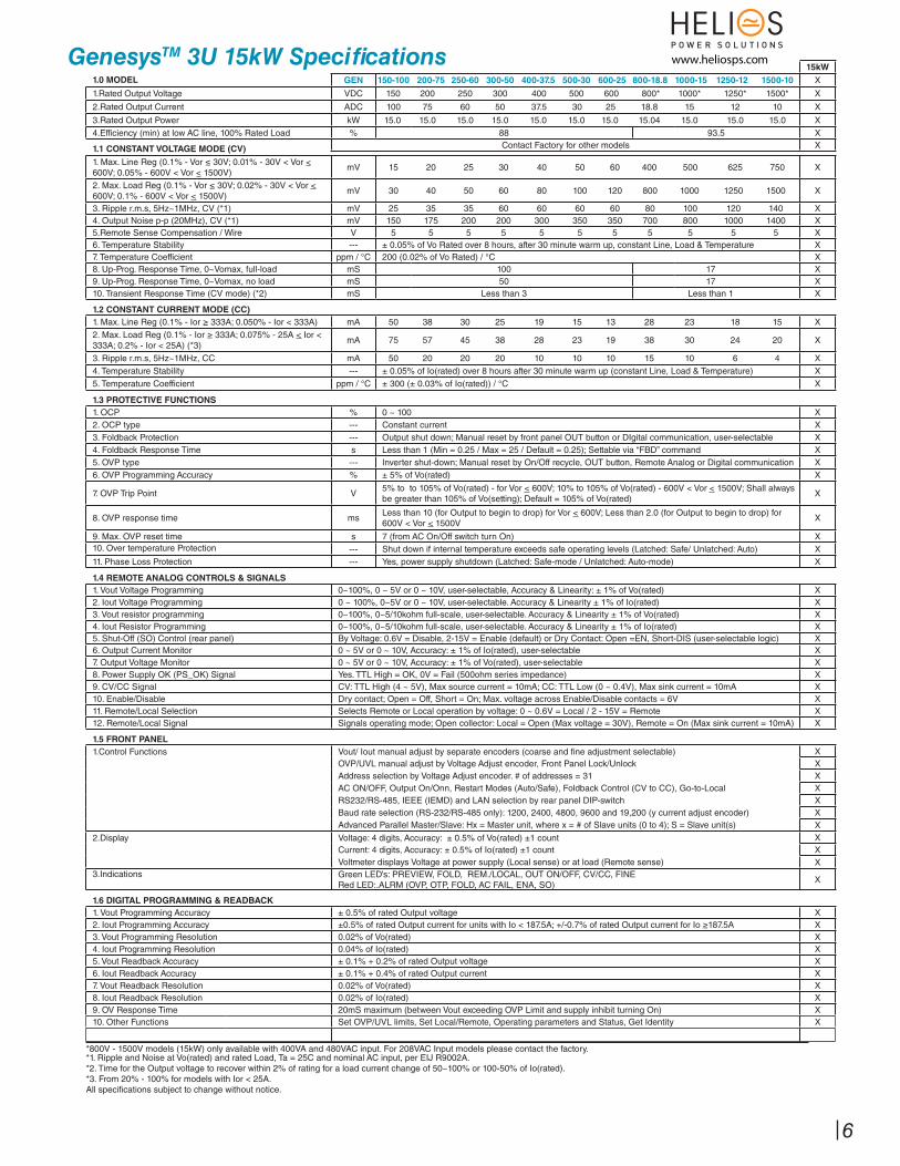
GenesysTM 3U 15kW Specifi cations15kW
1.0 MODEL GEN 150-100 200-75 250-60 300-50 400-37.5 500-30 600-25 800-18.8 1000-15 1250-12 1500-10 X
1.Rated Output Voltage VDC 150 200 250 300 400 500 600 800* 1000* 1250* 1500* X
2.Rated Output Current ADC 100 75 60 50 37.5 30 25 18.8 15 12 10 X
3.Rated Output Power kW 15.0 15.0 15.0 15.0 15.0 15.0 15.0 15.04 15.0 15.0 15.0 X4.Efficiency (min) at low AC line, 100% Rated Load % 88 93.5 X
1.1 CONSTANT VOLTAGE MODE (CV) Contact Factory for other models X
1. Max. Line Reg (0.1% - Vor ≤ 30V; 0.01% - 30V < Vor < 600V; 0.05% - 600V < Vor < 1500V)
mV 15 20 25 30 40 50 60 400 500 625 750 X
2. Max. Load Reg (0.1% - Vor ≤ 30V; 0.02% - 30V < Vor < 600V; 0.1% - 600V < Vor < 1500V)
mV 30 40 50 60 80 100 120 800 1000 1250 1500 X
3. Ripple r.m.s, 5Hz~1MHz, CV (*1) mV 25 35 35 60 60 60 60 80 100 120 140 X4. Output Noise p-p (20MHz), CV (*1) mV 150 175 200 200 300 350 350 700 800 1000 1400 X5.Remote Sense Compensation / Wire V 5 5 5 5 5 5 5 5 5 5 5 X6. Temperature Stability --- ± 0.05% of Vo Rated over 8 hours, after 30 minute warm up, constant Line, Load & Temperature X7. Temperature Coefficient ppm / °C 200 (0.02% of Vo Rated) / °C X8. Up-Prog. Response Time, 0~Vomax, full-load mS 100 17 X9. Up-Prog. Response Time, 0~Vomax, no load mS 50 17 X10. Transient Response Time (CV mode) (*2) mS Less than 3 Less than 1 X
1.2 CONSTANT CURRENT MODE (CC)
1. Max. Line Reg (0.1% - Ior ≥ 333A; 0.050% - Ior < 333A) mA 50 38 30 25 19 15 13 28 23 18 15 X
2. Max. Load Reg (0.1% - Ior ≥ 333A; 0.075% - 25A < Ior < 333A; 0.2% - Ior < 25A) (*3)
mA 75 57 45 38 28 23 19 38 30 24 20 X
3. Ripple r.m.s, 5Hz~1MHz, CC mA 50 20 20 20 10 10 10 15 10 6 4 X4. Temperature Stability --- ± 0.05% of Io(rated) over 8 hours after 30 minute warm up (constant Line, Load & Temperature) X5. Temperature Coefficient ppm / °C ± 300 (± 0.03% of Io(rated)) / °C X
1.3 PROTECTIVE FUNCTIONS
1. OCP % 0 ~ 100 X2. OCP type --- Constant current X3. Foldback Protection --- Output shut down; Manual reset by front panel OUT button or DIgital communication, user-selectable X4. Foldback Response Time s Less than 1 (Min = 0.25 / Max = 25 / Default = 0.25); Settable via “FBD” command X5. OVP type --- Inverter shut-down; Manual reset by On/Off recycle, OUT button, Remote Analog or Digital communication X6. OVP Programming Accuracy % ± 5% of Vo(rated) X
7. OVP Trip Point V5% to to 105% of Vo(rated) - for Vor < 600V; 10% to 105% of Vo(rated) - 600V < Vor < 1500V; Shall always be greater than 105% of Vo(setting); Default = 105% of Vo(rated)
X
8. OVP response time msLess than 10 (for Output to begin to drop) for Vor < 600V; Less than 2.0 (for Output to begin to drop) for 600V < Vor < 1500V
X
9. Max. OVP reset time s 7 (from AC On/Off switch turn On) X10. Over temperature Protection --- Shut down if internal temperature exceeds safe operating levels (Latched: Safe/ Unlatched: Auto) X11. Phase Loss Protection --- Yes, power supply shutdown (Latched: Safe-mode / Unlatched: Auto-mode) X
1.4 REMOTE ANALOG CONTROLS & SIGNALS
1. Vout Voltage Programming 0~100%, 0 ~ 5V or 0 ~ 10V, user-selectable, Accuracy & Linearity: ± 1% of Vo(rated) X2. Iout Voltage Programming 0 ~ 100%, 0~5V or 0 ~ 10V, user-selectable. Accuracy & Linearity ± 1% of Io(rated) X3. Vout resistor programming 0~100%, 0~5/10kohm full-scale, user-selectable. Accuracy & Linearity ± 1% of Vo(rated) X4. Iout Resistor Programming 0~100%, 0~5/10kohm full-scale, user-selectable. Accuracy & Linearity ± 1% of Io(rated) X5. Shut-Off (SO) Control (rear panel) By Voltage: 0.6V = Disable, 2-15V = Enable (default) or Dry Contact: Open =EN, Short-DIS (user-selectable logic) X6. Output Current Monitor 0 ~ 5V or 0 ~ 10V, Accuracy: ± 1% of Io(rated), user-selectable X7. Output Voltage Monitor 0 ~ 5V or 0 ~ 10V, Accuracy: ± 1% of Vo(rated), user-selectable X8. Power Supply OK (PS_OK) Signal Yes. TTL High = OK, 0V = Fail (500ohm series impedance) X9. CV/CC Signal CV: TTL High (4 ~ 5V), Max source current = 10mA; CC: TTL Low (0 ~ 0.4V), Max sink current = 10mA X10. Enable/Disable Dry contact; Open = Off, Short = On; Max. voltage across Enable/Disable contacts = 6V X11. Remote/Local Selection Selects Remote or Local operation by voltage: 0 ~ 0.6V = Local / 2 - 15V = Remote X12. Remote/Local Signal Signals operating mode; Open collector: Local = Open (Max voltage = 30V), Remote = On (Max sink current = 10mA) X
1.5 FRONT PANEL
1.Control Functions Vout/ Iout manual adjust by separate encoders (coarse and fi ne adjustment selectable) XOVP/UVL manual adjust by Voltage Adjust encoder, Front Panel Lock/Unlock XAddress selection by Voltage Adjust encoder. # of addresses = 31 XAC ON/OFF, Output On/Onn, Restart Modes (Auto/Safe), Foldback Control (CV to CC), Go-to-Local XRS232/RS-485, IEEE (IEMD) and LAN selection by rear panel DIP-switch XBaud rate selection (RS-232/RS-485 only): 1200, 2400, 4800, 9600 and 19,200 (y current adjust encoder) XAdvanced Parallel Master/Slave: Hx = Master unit, where x = # of Slave units (0 to 4); S = Slave unit(s) X
2.Display Voltage: 4 digits, Accuracy: ± 0.5% of Vo(rated) ±1 count XCurrent: 4 digits, Accuracy: ± 0.5% of Io(rated) ±1 count XVoltmeter displays Voltage at power supply (Local sense) or at load (Remote sense) X
3.Indications Green LED’s: PREVIEW, FOLD, REM./LOCAL, OUT ON/OFF, CV/CC, FINERed LED:.ALRM (OVP, OTP, FOLD, AC FAIL, ENA, SO)
X
1.6 DIGITAL PROGRAMMING & READBACK
1. Vout Programming Accuracy ± 0.5% of rated Output voltage X2. Iout Programming Accuracy ±0.5% of rated Output current for units with Io < 187.5A; +/-0.7% of rated Output current for Io ≥187.5A X3. Vout Programming Resolution 0.02% of Vo(rated) X4. Iout Programming Resolution 0.04% of Io(rated) X5. Vout Readback Accuracy ± 0.1% + 0.2% of rated Output voltage X6. Iout Readback Accuracy ± 0.1% + 0.4% of rated Output current X7. Vout Readback Resolution 0.02% of Vo(rated) X8. Iout Readback Resolution 0.02% of Io(rated) X9. OV Response Time 20mS maximum (between Vout exceeding OVP Limit and supply inhibit turning On) X10. Other Functions Set OVP/UVL limits, Set Local/Remote, Operating parameters and Status, Get Identity X
*800V - 1500V models (15kW) only available with 400VA and 480VAC input. For 208VAC Input models please contact the factory.*1. Ripple and Noise at Vo(rated) and rated Load, Ta = 25C and nominal AC input, per EIJ R9002A.*2. Time for the Output voltage to recover within 2% of rating for a load current change of 50~100% or 100-50% of Io(rated).*3. From 20% - 100% for models with Ior < 25A.All specifi cations subject to change without notice.
6
www.heliosps.com
GenesysTM 3U 10/15kW
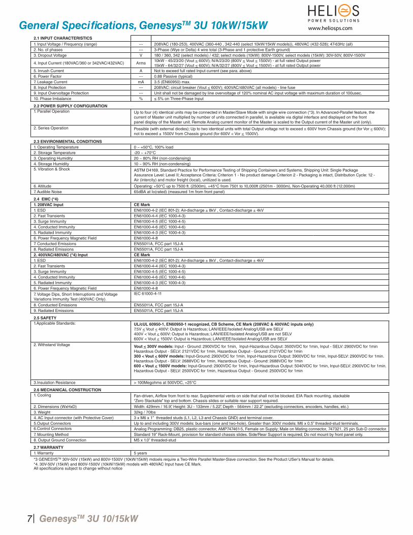
General Specifi cations, GenesysTM 3U 10kW/15kW2.1 INPUT CHARACTERISTICS
1. Input Voltage / Frequency (range) --- 208VAC (180-253), 400VAC (360-440 , 342-440 (select 10kW/15kW models)), 480VAC (432-528); 47-63Hz (all)2. No. of phases --- 3-Phase (Wye or Delta) 4 wire total (3-Phase and 1 protective Earth ground)3. Dropout Voltage V 180 / 360, 342 (select models) / 432; select models (10kW): 800V-1500V, select models (15kW): 30V-50V, 800V-1500V
4. Input Current (180VAC/360 or 342VAC/432VAC) Arms10kW - 45/23/20 (Vout < 600V); N/A/23/20 (800V < Vout < 1500V) - at full rated Output power15kW - 64/32/27 (Vout < 600V); N/A/32/27 (800V < Vout < 1500V) - at full rated Output power
5. Inrush Current A Not to exceed full rated Input current (see para. above)6. Power Factor --- 0.88 Passive (typical)7. Leakage Current mA 3.5 (EN60950) max.8. Input Protection --- 208VAC: circuit breaker (Vout < 600V); 400VAC/480VAC (all models) - line fuse9. Input Overvoltage Protection --- Unit shall not be damaged by line overvoltage of 120% nominal AC input voltage with maximum duration of 100usec.10. Phase Imbalance % ≤ 5% on Three-Phase Input
2.2 POWER SUPPLY CONFIGURATION
1. Parallel Operation Up to four (4) identical units may be connected in Master/Slave Mode with single wire connection (*3). In Advanced-Parallel feature, thecurrent of Master unit multiplied by number of units connected in parallel, is available via digital interface and displayed on the frontpanel display of the Master unit. Remote Analog current monitor of the Master is scaled to the Output current of the Master unit (only).
2. Series Operation Possible (with external diodes); Up to two identical units with total Output voltage not to exceed ± 600V from Chassis ground (for Vor < 600V); not to exceed ± 1500V from Chassis ground (for 600V < Vor < 1500V).
2.3 ENVIRONMENTAL CONDITIONS
1. Operating Temperature 0 ~ +50°C, 100% load2. Storage Temperature -20 ~ +70°C3. Operating Humidity 20 ~ 80% RH (non-condensing)4. Storage Humidity 10 ~ 90% RH (non-condensing)5. Vibration & Shock ASTM D4169, Standard Practice for Performance Testing of Shipping Containers and Systems, Shipping Unit: Single Package
Assurance Level: Level II; Acceptance Criteria: Criterion 1 - No product damage Criterion 2 - Packaging is intact, Distribution Cycle: 12 -Air (intercity) and motor freight (local), unitized is used.
6. Altitude Operating: +50°C up to 7500 ft. (2500m), +45°C from 7501 to 10,000ft (2501m - 3000m), Non-Operating 40,000 ft (12,000m)7. Audible Noise 65dBA at Io(rated) (measured 1m from front panel)
2.4 EMC (*4)
1. 208VAC Input CE Mark
1. ESD EN61000-4-2 (IEC 801-2): Air-discharge ± 8kV , Contact-discharge ± 4kV2. Fast Transients EN61000-4-4 (IEC 1000-4-3)3. Surge Immunity EN61000-4-5 (IEC 1000-4-5)4. Conducted Immunity EN61000-4-6 (IEC 1000-4-6)5. Radiated Immunity EN61000-4-3 (IEC 1000-4-3)6. Power Frequency Magnetic Field EN61000-4-87. Conducted Emissions EN55011A, FCC part 15J-A8. Radiated Emissions EN55011A, FCC part 15J-A2. 400VAC/480VAC (*4) Input CE Mark
1. ESD EN61000-4-2 (IEC 801-2): Air-discharge ± 8kV , Contact-discharge ± 4kV2. Fast Transients EN61000-4-4 (IEC 1000-4-3)3. Surge Immunity EN61000-4-5 (IEC 1000-4-5)4. Conducted Immunity EN61000-4-6 (IEC 1000-4-6)5. Radiated Immunity EN61000-4-3 (IEC 1000-4-3)6. Power Frequency Magnetic Field EN61000-4-8
7. Voltage Dips, Short Interruptions and Voltage Variations Immunity Test (400VAC Only).
IEC 61000-4-11
8. Conducted Emissions EN55011A, FCC part 15J-A9. Radiated Emissions EN55011A, FCC part 15J-A
2.5 SAFETY
1.Applicable Standards: UL/cUL 60950-1, EN60950-1 recognized, CB Scheme, CE Mark (208VAC & 400VAC inputs only)
7.5V < Vout < 400V: Output is Hazardous; LAN/IEEE/Isolated Analog/USB are SELV400V < Vout < 600V: Output is Hazardous; LAN/IEEE/Isolated Analog/USB are not SELV600V < Vout < 1500V: Output is Hazardous; LAN/IEEE/Isolated Analog/USB are SELV
2. Withstand Voltage Vout < 300V models: Input - Ground: 2900VDC for 1min, Input-Hazardous Output: 3500VDC for 1min, Input - SELV: 2900VDC for 1minHazardous Output - SELV: 2121VDC for 1min, Hazardous Output - Ground: 2121VDC for 1min300 < Vout < 600V models: Input-Ground: 2900VDC for 1min, Input-Hazardous Output: 3900VDC for 1min, Input-SELV: 2900VDC for 1min.Hazardous Output - SELV: 2688VDC for 1min, Hazardous Output - Ground: 2688VDC for 1min600 < Vout < 1500V models: Input-Ground: 2900VDC for 1min, Input-Hazardous Output: 5040VDC for 1min, Input-SELV: 2900VDC for 1min.Hazardous Output - SELV: 2500VDC for 1min, Hazardous Output - Ground: 2500VDC for 1min
3.Insulation Resistance > 100Megohms at 500VDC, +25°C
2.6 MECHANICAL CONSTRUCTION
1. Cooling Fan-driven, Airfl ow from front to rear. Supplemental vents on side that shall not be blocked. EIA Rack mounting, stackable“Zero Stackable” top and bottom. Chassis slides or suitable rear support required.
2. Dimensions (WxHxD) Width: 429mm / 16.9”, Height: 3U - 133mm / 5.22”, Depth - 564mm / 22.2” (excluding connectors, encoders, handles, etc.)3. Weight 32kg / 70lbs4. AC Input connector (with Protective Cover) 3 x M6 x 1” threaded studs (L1, L2, L3 and Chassis GND) and terminal cover.5.Output Connectors Up to and including 300V models: bus-bars (one and two-hole). Greater than 300V models: M6 x 0.5” threaded-stud terminals.6.Control Connectors Analog Programming: DB25, plastic connector, AMP747461-5, Female on Supply; Male on Mating connector, 747321, 25 pin Sub-D connector.7. Mounting Method Standard 19” Rack-Mount, provision for standard chassis slides. Side/Rear Support is required; Do not mount by front panel only.8. Output Ground Connection M5 x 1.0” threaded-stud
2.7 WARRANTY
1. Warranty 5 years
*3 GENESYSTM 30V-50V (15kW) and 800V-1500V (10kW/15kW) mdoels require a Two-Wire Parallel Master-Slave connection. See the Product USer’s Manual for details.*4. 30V-50V (15kW) and 800V-1500V (10kW/15kW) models with 480VAC Input have CE Mark.All specifi cations subject to change without notice
7
www.heliosps.com
8
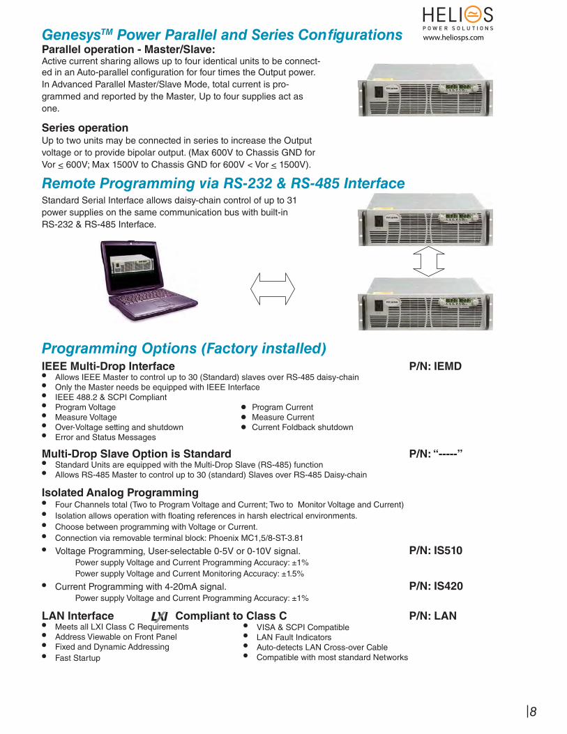
Parallel operation - Master/Slave:Active current sharing allows up to four identical units to be connect-ed in an Auto-parallel confi guration for four times the Output power.In Advanced Parallel Master/Slave Mode, total current is pro-grammed and reported by the Master, Up to four supplies act as one.
Series operationUp to two units may be connected in series to increase the Output voltage or to provide bipolar output. (Max 600V to Chassis GND for Vor < 600V; Max 1500V to Chassis GND for 600V < Vor < 1500V).
Remote Programming via RS-232 & RS-485 InterfaceStandard Serial Interface allows daisy-chain control of up to 31power supplies on the same communication bus with built-inRS-232 & RS-485 Interface.
Programming Options (Factory installed)IEEE Multi-Drop Interface P/N: IEMD• Allows IEEE Master to control up to 30 (Standard) slaves over RS-485 daisy-chain• Only the Master needs be equipped with IEEE Interface• IEEE 488.2 & SCPI Compliant• Program Voltage •• Program Current• Measure Voltage •• Measure Current• Over-Voltage setting and shutdown •• Current Foldback shutdown• Error and Status Messages
Multi-Drop Slave Option is Standard P/N: “-----” • Standard Units are equipped with the Multi-Drop Slave (RS-485) function• Allows RS-485 Master to control up to 30 (standard) Slaves over RS-485 Daisy-chain
LAN Interface Compliant to Class C P/N: LAN• Meets all LXI Class C Requirements• Address Viewable on Front Panel• Fixed and Dynamic Addressing• Fast Startup
• VISA & SCPI Compatible• LAN Fault Indicators• Auto-detects LAN Cross-over Cable• Compatible with most standard Networks
Isolated Analog Programming• Four Channels total (Two to Program Voltage and Current; Two to Monitor Voltage and Current)• Isolation allows operation with fl oating references in harsh electrical environments.• Choose between programming with Voltage or Current.• Connection via removable terminal block: Phoenix MC1,5/8-ST-3.81
• Voltage Programming, User-selectable 0-5V or 0-10V signal. P/N: IS510 Power supply Voltage and Current Programming Accuracy: ±1%
Power supply Voltage and Current Monitoring Accuracy: ±1.5%
• Current Programming with 4-20mA signal. P/N: IS420 Power supply Voltage and Current Programming Accuracy: ±1%
GenesysTM Power Parallel and Series Confi gurations www.heliosps.com
GenesysTM 3U 10/15kW
12121212121212121212121212121212
J2 SW1
IN OUT
J1 J3
RS 485/232
TORQUE TERMINALTO 32 IN-LBS.
CAUTION:
(3.5NM)
J2
SW1
J1 J3
RS 485/232 OUT IN
TORQUE TERMINALCAUTION:
TO 32 IN-LBS. (3.5NM)
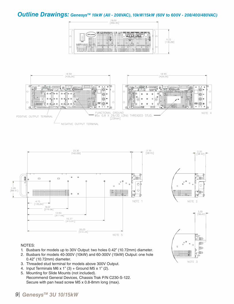
NOTES:1. Busbars for models up to 30V Output: two holes 0.42” (10.72mm) diameter.2. Busbars for models 40-300V (10kW) and 60-300V (15kW) Output: one hole 0.42” (10.72mm) diameter.3. Threaded stud terminal for models above 300V Output.4. Input Terminals M6 x 1” (3) + Ground M5 x 1” (2).5. Mounting for Slide Mounts (not included). Recommend General Devices, Chassis Trak P/N C230-S-122. Secure with pan head screw M5 x 0.8-8mm long (max).
Outline Drawings: GenesysTM 10kW (All - 208VAC), 10kW/15kW (60V to 600V - 208/400/480VAC)
9
10
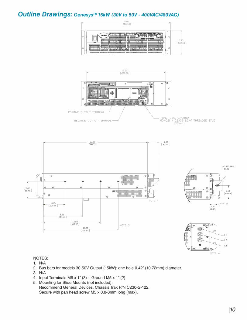
Outline Drawings: GenesysTM 15kW (30V to 50V - 400VAC/480VAC)
120.65
8.63
317.50
219.08
16.38415.93
22.85580.39
2.5063.45
4.75
12.50
L1
L2
L3
68.492.70
28.051.10
0.422 THRU
88.46
10.72
NOTES:1. N/A2. Bus bars for models 30-50V Output (15kW): one hole 0.42” (10.72mm) diameter.3. N/A4. Input Terminals M6 x 1” (3) + Ground M5 x 1” (2)5. Mounting for Slide Mounts (not included). Recommend General Devices, Chassis Trak P/N C230-S-122. Secure with pan head screw M5 x 0.8-8mm long (max).
GenesysTM 3U 10/15kW
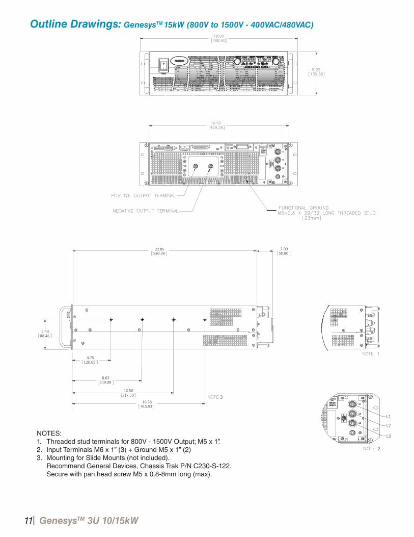
Outline Drawings: GenesysTM 15kW (800V to 1500V - 400VAC/480VAC)
2
3
120.65
8.63
317.50
219.08
16.38415.93
22.85580.39
2.0050.80
4.75
12.50
L1
L2
L3
88.46
NOTES:1. Threaded stud terminals for 800V - 1500V Output; M5 x 1”.2. Input Terminals M6 x 1” (3) + Ground M5 x 1” (2)3. Mounting for Slide Mounts (not included). Recommend General Devices, Chassis Trak P/N C230-S-122. Secure with pan head screw M5 x 0.8-8mm long (max).
11
12
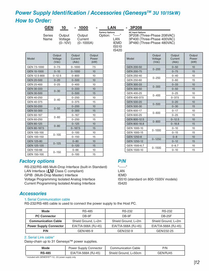
Power Supply Identifi cation / Accessories (GenesysTM 3U 10/15kW)
How to Order:
GEN 10 - 1000 - LAN - 3P208Factory Options AC Input Options
Series Output Output Option: “-----” 3P208 (Three-Phase 208VAC)Name Voltage Current LAN 3P400 (Three-Phase 400VAC)
(0~10V) (0~1000A) IEMD 3P480 (Three-Phase 480VAC)IS510IS420
ModelOutputVoltage(Vdc)
OutputCurrent (Adc)
OutputPower (kW)
GEN 7.5-1000 0~7.5 0~1000 7.5
GEN 10-1000 0~10 0~1000 10
GEN 12.5-800 0~12.5 0~800 10
GEN 20-500 0~20 0~500 10
GEN 25-400 0~25 0~400 10
GEN 30-3330~30
0~333 10
GEN 30-500 0~500 15
GEN 40-2500~40
0~250 10
GEN 40-375 0~375 15
GEN 50-2000~50
0~200 10
GEN 50-300 0~300 15
GEN 60-1670~60
0~167 10
GEN 60-250 0~250 15
GEN 80-1250~80
0~125 10
GEN 80-187.5 0~187.5 15
GEN 100-1000~100
0~100 10
GEN 100-150 0~150 15
GEN 125-800~125
0~80 10
GEN 125-120 0~120 15
GEN 150-660~150
0~66 10
GEN 150-100 0~100 15
ModelOutputVoltage(Vdc)
OutputCurrent (Adc)
OutputPower (kW)
GEN 200-500~200
0~50 10
GEN 200-75 0~75 15
GEN 250-400~250
0~40 10
GEN 250-60 0~60 15
GEN 300-330~300
0~33 10
GEN 300-50 0~50 15
GEN 400-250~400
0~25 10
GEN 400-37.5 0~37.5 15
GEN 500-200~500
0~20 10
GEN 500-30 0~30 15
GEN 600-170~600
0~17 10
GEN 600-25 0~25 15
GEN 800-12.50~800
0~12.5 10
GEN 800-18.8 0~18.8 15
GEN 1000-100~1000
0~10 10
GEN 1000-15 0~15 15
GEN 1250-80~1250
0~8 10
GEN 1250-12 0~12 15
GEN 1500-6.70~1500
0~6.7 10
GEN 1500-10 0~10 15
Factory options P/N RS-232/RS-485 Multi-Drop Interface (built-in Standard) “------” LAN Interface ( Class C compliant) LAN GPIB (Multi-Drop Master) Interface IEMD Voltage Programming Isolated Analog Interface IS510 (standard on 800-1500V models) Current Programming Isolated Analog Interface IS420
Accessories 1. Serial Communication cable RS-232/RS-485 cable is used to connect the power supply to the Host PC.
Mode RS-485 RS-232 RS-232
PC Connector DB-9F DB-9F DB-25F
Communication Cable Shield Ground, L=2m Shield Ground, L=2m Shield Ground, L=2m
Power Supply Connector EIA/TIA-568A (RJ-45) EIA/TIA-568A (RJ-45) EIA/TIA-568A (RJ-45)
P/N GEN/485-9 GEN/232-9 GEN/232-25
2. Serial Link cable* Daisy-chain up to 31 Genesys™ power supplies.
Mode Power Supply Connector Communication Cable P/N
RS-485 EIA/TIA-568A (RJ-45) Shield Ground, L=50cm GEN/RJ45* Included with GENESYSTM-1U, -2U power supply only.