Gel-Sphere-Pac Fule for Termal Reactors -- Assessment of ...
196
U\D r--- ___ 3 445b 0515123 3 ff@!r [Rl @ff f If , , Ilo009>OOIlolF@OOV @@[?\7 00 1Iil@li' li'@ OJ} }7OOOO 15®im@@lfil@ @O»@.OOl »@@ fi>@®dl Hoo (;)(ffij)@ wo1lfu @OOdI 1lfu@ wUDD @ltro@OO(ij@ @l O@l@lOOo qOll-fM: "(I Il(J Ii Ii , &i1 [ffiJ!W] @'illillill 00]] 1TIlli !illJJU!IDJ
Transcript of Gel-Sphere-Pac Fule for Termal Reactors -- Assessment of ...

~[K
~D~~ UD UD~ ~~lJ~W
r--- ___
3 445b 0515123 3
~reg~=~[pgt~regrreg=[pgt~~ f(UJreg~ ffr
If~regrm~~ [Rl reg~~ftr~=~~~reg~~mrilregllilft ff f ~bgt[[O~~ftOcopy1lil Ifreg~~Ililcopy~copyW
~1lilcQ] ~ [[[[~cQ]o~~acopy[fjj [Pgtreg[[~copy[[m~Ilil~reg
Ilo009gtOOIlolFOOV
(6~~liIKS~[L IKS~~~~~ [LQreg~~IKS1
~ ooIDliiJllll~
[s08~~~7 [1)8~ [7 00 1Iilli li~tml~I~~ li tmlliW~~ ~IKS~
OJ 7OOOO wH~ 15regimlfil OraquoOOl raquo 1lfuH~ ~ooll1o figtregdl Hoo ()(ffij) wo1lfu ~11i) OOdI 1lfu D6~0reg1l7 wUDD ltroOO(ij l OllOOo
qOll-fM O~CJ~IJ (I Il(J Ii Ii
~im ampi1 [ffiJW] illillill ~[J[[R]
00]] 1TIlli illJJUIDJ ~ampDm
~rw~
Printed in the United States of America Available from National Technical Information Service
US Department of Commerce 5285 Port Royal Road Springfield Virginia 22161
NTIS price codes-Printed Copy A09 Microfiche A01
This report was prepared as an account of work sponsored by an agency of the United States Government Neither the United States nor any agency thereof nor any of their employees makes any warranty expressed or implied or assumes any legal liability or responsibility for any third partys use or the results of such use of any information apparatus product or process disclosed in this report or represents that its use by such third party would not infringe privately owned rights
ORNL-5469 Distribution Categories UC-77 UC-78 and UC-83
Contract No W-7405-eng-26
METALS AND CERAMICS CHEMICAL TECHNOLOGY
DIVISION DIVISION
GEL-SPHERE-PAC FUEL FOR THERMAL REACTORS - ASSESSMENT OF FABRICATION TECHNOLOGY AND IRRADIATION PERFORMANCE
Compiled by
R L Beatty R E Norman
K J Notz
Contributions by
E J Allen C C Haws A E Pasto P Angelini J A Horak R D Spence J M Begovich w J Lackey R R Suchomel P A Haas J E Mack
Date Published November 1979
OAK RIDGE NATIONAL LABORATORY Oak Ridge Tennessee 37830
operated by UNION CARBIDE CORPORATION
for the DEPARTMENT OF ENERGY
3 445b 0515123 3 ~-------~---
bull bull
bull bull
CONTENrS
ABSTRACT 1
EXECUTIVE SUMMARY bull bull 2~
1 INTRODUCTION 9
11 OVERVIEW bull ~ bull bull bull 9 12 HISTORICAL 12 13 PRESENT PROGRAMS bull J4bullbullbullbullbullbullbull ~ ~~
14 REFERENCES bullbullbullbull L5~
2 PREPARATION OF CERAMIC FUEL SPHERES BY GEL PROCESSES 17
21 WATER EXTRACTION GELATION ~ 18
211 Sol Preparation bull bull bull 20
212 Sphere Forming and Gelation 21
21 3 Drying and Sintering 23~
21 4 Application to Th02 bull bull bull bull bull 24 2141 Formation of Gel Spheres middot 2gt 2142 Sphere Drying and Sintering 26
215 Application to U02 bullbull 27
2151 Preparation of Sols 28middot 2152 Preparation of Spheres bull - 30
2153 Drying and Sintering bullbull middot 3
2l 54 Results and Material Balan~e bull middot middot 32 2155 Conclusions ~ 34
216 Application to (ThU)02 bullbullbullbullbullbullbull 34
2161 Sol Preparation bullbullbull middot 35 2162 Preparation of Spheres 36
2163 Drying and Sintering bullbull bull fII bull 37
2164 Conclusions on (ThU)02
middot Sphere Production 38
217 Application to (UPu)02 bullbullbullbullbull 38
2371 Precipitation Thermal Denitratlon for Pu02 Sol Preparation bull bull bull
217 2 Solvent Extra~tion Preparation ~of PuOZ Sols bull bull bull bull bull bull bull 41
22 EXTERNAL CHEMICAL GELATION bull bull bull bull bull J 45 221 Sol and Broth Prepltlration bull 49 222 Sphere Formation and Gelation bull 51
iii
iv
223 Aging Washing and Dehydrating 52
224 Drying bull bull bull bull 52
225 Calcining and Sintering 53
226 Application to Th02 bull bull bull bull bull bull bull 54
227 Application to U02 56
228 Application to (ThU)02 bull 57
229 Application to (U Pu)02 bull 58
2210 Summary of Pilot Plants 60
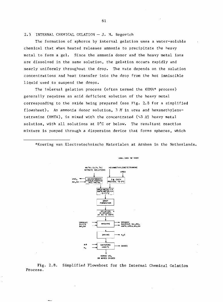
23 INTERNAL CHEMICAL GELATION bullbull 61
23 1 Broth Preparation for UOZ bull 62
232 Sphere Forming and Gelation bull 63
2321 Production of Large Spheres 64
2322 Production of Medium-Size Spheres 65
2323 Production of Fines 65
233 Washing 66
234 Drying 67
235 Calcining and Sintering 68
236 Application to U02 68
237 Application to Other Oxides 70
24 APPLICATION OF DROP FORMATION PROCEDURES TO MEET GEL-SPHERE-PAC REQUIREMENTS bull 72
241 Drop Weight Mechanism bull bullbullbullbullbullbull 72
242 Laminar Breakup of Jetsmiddot bull bull bull bull bull bull bull 74
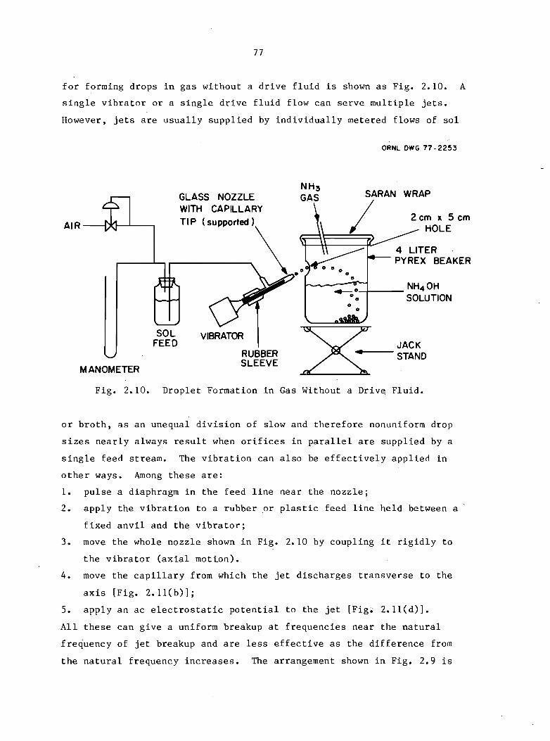
243 Laminar Jet Breakup Apparatus bullbull 76
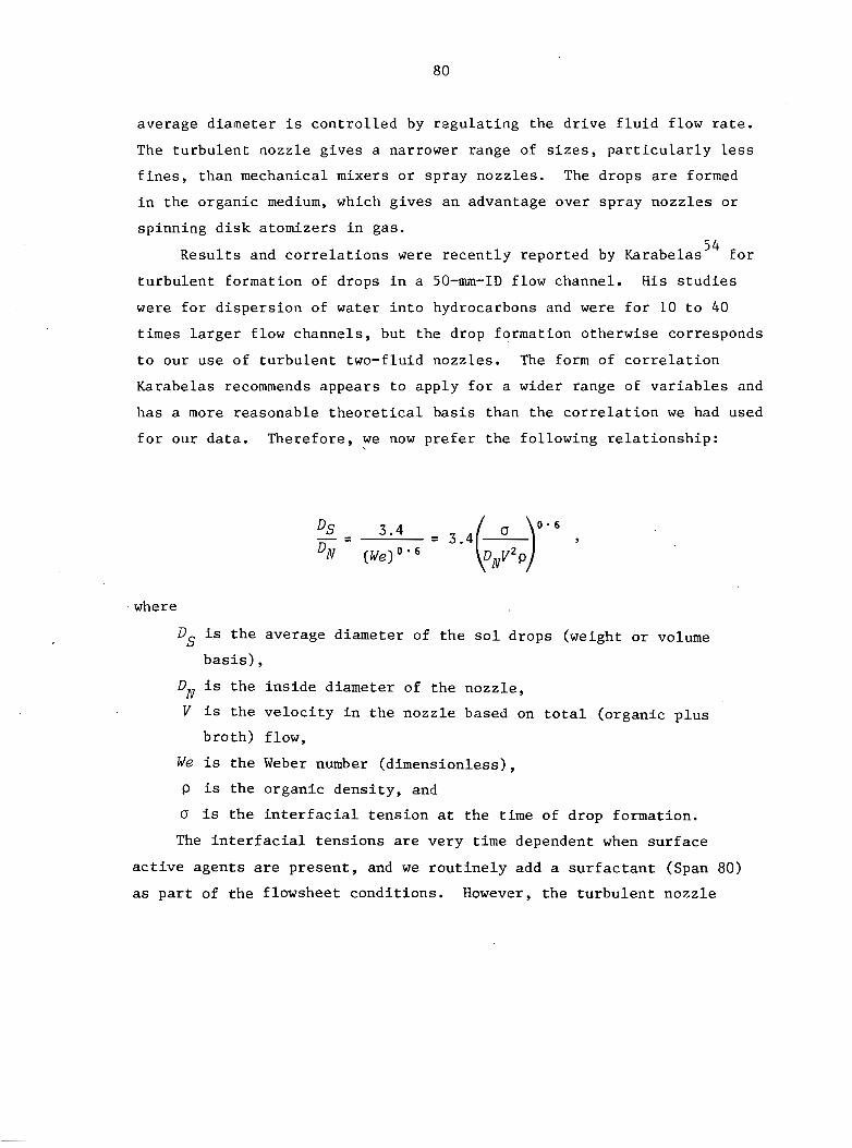
244 Turbulent Breakup in Two-Fluid Nozzlesmiddot 79
245 Capacity Limitations bullbullbullbull 82
25 GEL-SPHERE CALCINATION AND SINTERING bull 85 251 Phenomenological Considerations 85
26 PRODUCT SPHERE CHARACTERIZATION 90
261 Density bullbullbullbullbullbullbullbullbull 91
262 Size and Shape 91
263 Chemistry bullbull 93
264 Strength bull ~ bull 94
265 Microstructure 94
95
v
27 CRITERIA FOR PROCESS SELECTION AND SCALE-UP
271 Scale-up of Sphere Fabrication 95
272 Feed Preparation 95
273 Sphere Formation and Gelation 97
274 Washing 98
275 Drying 98
276 Sintering 98
28 REMOTE APPLICATIONS 98
281 Significant Engineering Scale Demonstrations bullbull bull bull 99
28-2 Engineering Design and Operational Concepts bullbullbullbullbullbullbullbullbullbullbullbullbullbull 100
283 Identification of Potential Operating Difficulties bullbullbullbull bull bull bull bull 102
29 REFERENCES bullbull 103
3 -FABRICATION OF FUEL RODS BY SPHERE-PAC TECHNIQUES bull bull 111
31 PACKING THEORY 111
32 EXPERIMENTAL RESULTS bull bull 114
33 LOADING EQUIPMENT AND METHODS 118
331 Vibrational Input bullbullbull 119
bull e- bull bull332 Fuel Sphere Blending and Loading 122
333 Compaction Aids bullbullbullbullbull 124
334 Postloading Procedures 124 ~-
34 ROD INSPECTION bull bull 126
341 Dimensional Inspection 126
342 Density Homogeneity Assay and Fuel Column Length bull bull bull bull bull bull bull 127
343 Impurity Analysis 129
344 Weld Integrity 129
35 PROCESS SCALE-UP CONSIDERATIONS 129
351 Sphere-Pac Loading 131
352 Fuel Handling 132
36 REMOTE APPLICATION 134
37 REFERENCES bullbullbullbull 135
vi
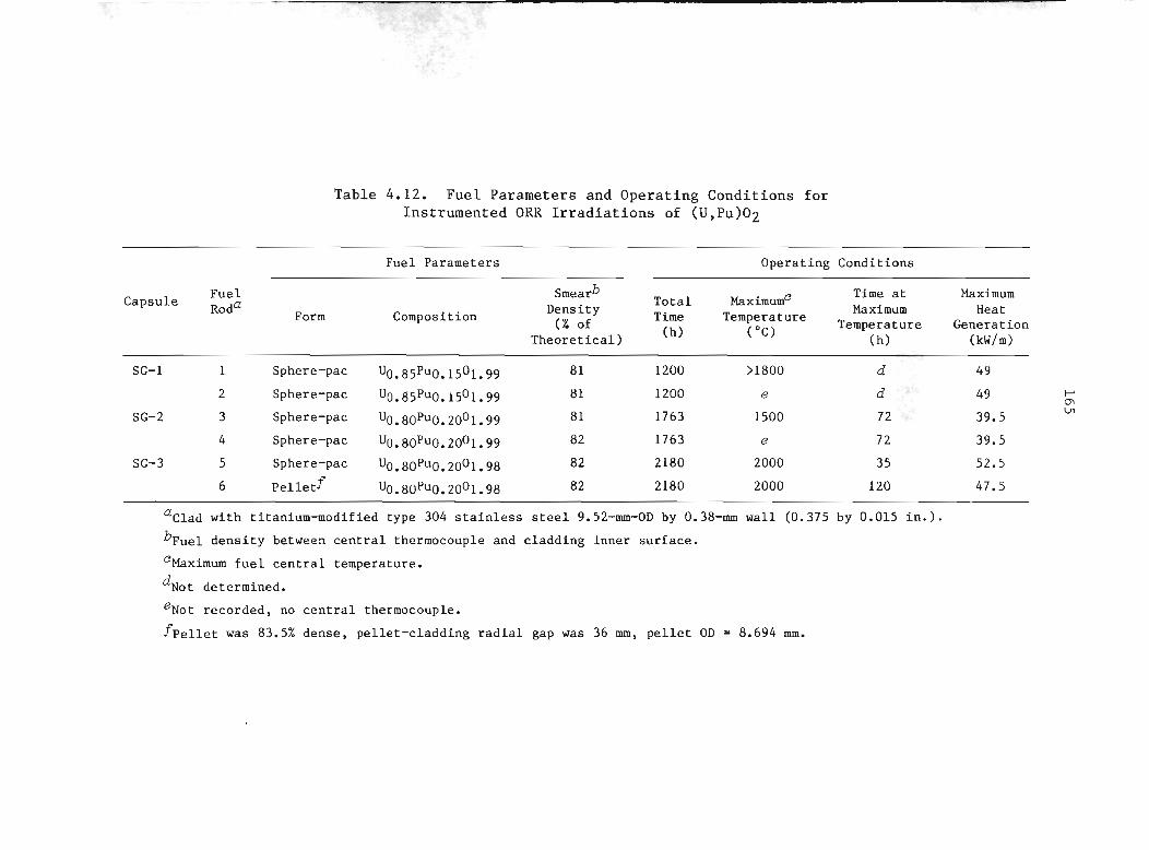
4 IRRADIATION PERFORMANCE OF SPHERE-PAC FUELS 141
4 1 IRRADIATION OF THERMAL REACTOR FUELS 141middot middot middot middot middot middot 41 1 Studies at ECN Petten Netheriands 141middot 412 Studies at Riso Denmark 155middot middot middot middot 4 1 3 Studies at KFA Juich FRG bull 156
414 -Studies at CNEN Rome Italy 157middot middot middot middot middot middot middot middot 415 Assessment of Tests to Date 159middot middot
42 THERMAL REACTOR IRRADIATIONS OF FAST
middot middot middot middotREACTOR OXIDE FUELS 160
421 Studies at ORNL 160middot middot middot middot middot middot middot middot middot 422 Studies at Karlsruhe FRG 170
43 REFERENCES 170middot middot middot middot middot middot middot middot middot 5 STATUS AND RECOMMENDED FUTURE WORK 173
51 SOL AND BROTH PREPARATION 173middot middot middot middot middot middot middot middot 511 Status 173middot middot middot middot 512 Future Work 174middot middot middot middot middot middot middot middot middot
52 FORMING AND WASHING OF GEL SPHERES 175
521 Status 175middot middot middot middot 522 Future Work 176middot middot middot middot middot middot middot middot
53 DRYING OF GEL SPHERES 176middot middot middot middot middot middot 531 Status 176middot middot middot middot 530 2 Future Work 176middot bull middot middot middot middot bull
54 CALCINING AND SINTERING 177bull middot 541 Status 177middot middot bull middot middot middot middot middot middot middot bull middot middot middot middot 542 Future Work bull 177middot middot middot middot middot middot
55 CHARACTERIZATION OF SPHERES 178~ bullmiddot middot 551 Status 178middot middot - middot middot middot middot middot 552 Future Work bull 178middot middot middot middot bull middot middot bull middot middot bull middot middot bull middot
56 SPHERE-PAC LOADING AND ROD INSPECTION 179middot middot middot middot 561 Status 179middot bull 562 Future Work 179middot bull middot middot bull middot middot bull middot middot
57 IRRADIATION PERFORMANCE 180bull middot middot middot middot middot bull middot bull 571 Status 180
572 Future Work bull 180middot middot bull bull middot bull bull middot middot bull bull bull bull middot bull middotmiddot bull
vii
58 SCRAP RECYCLE 181
581 Status 181
582 Future Work 181
59 IN-PLANT WASTE TREATMENT 181
591 Status 181
592 Future Work bull 182
510 COMMERCIAL FACILITY 182
5101 Status 182
5102 Future ~Jork bull 182
511 REFERENCES 183
r
GEL-SPHERE-PAC FUEL FOR THERMAL REACTIONS ASSESSMENT OF FABRICATION TECHNOLOGY AND IRRADIATION PERFORMANCE
Compiled by R L Beatty R E Norman and K J Notz
ABSTRACT
Recent interest in proliferation-resistant fuel cycles for light-water reactors has focused attention on spiked plushytonium and 233U-Th fuels which will require remote refabrishycation The gel-sphere-pac process for fabricating metal-clad fuel elements has drawn special attention because it involves fewer process steps and fewer mechanically intensive steps than pellet technology all operations deal with either liquids or microspheres which are free-flowing and relatively dust-free These fabrication process characteiistics should also enable lower personnel exposures during both fabrication and maintenance operations
Gel-sphere-pac fabrication technology involves two major areas the preparation of fuel spheres of high density and loading these spheres into rods in an efficiently packed geometry Gel sphere preparation involves three major steps preparation of a sol or of a special solution (broth) gelation of droplets of sol or broth to give semirigid spheres of controlled size and drying and sintering these spheres to a high density Gelation may be accomplished by water extracshytion (suitable only for sols) or ammonia gelation (suitable for both sols and broths but used almost exclusively with broths) Ammonia gelation can be accomplished either extershynally via ammonia gas and ammonium hydroxide or internally via an added ammonia generator such as hexamethylenetetramine Sphere-pac fuel rod fabrication involves controlled blending and metering of three sizes of spheres into the rod and packing by low- to medium-energy vibration to achieve about 88 smear density these sizes have diametral ratios of about 40101 and are blended in size fraction amounts of about 60 coarse 18 medium and 22 fine
In addition to fabrication process advantages irrashydiation test results available to date indicate that sphereshypac fuel performs at least as well as pellet fuel and may in fact offer an advantage in significantly reducing mechanical and chemical interaction between the fuel and cladding
From the standpoint of overall process complexity and economics it should be noted that the normal feed for gel sphere preparation heavy metal nitrate solution is the usual
Chemical Technology Division
I
2
product of fuel reprocessing so that fabrication of gel spheres performs all the functions performed by both conver~ sion and pellet fabrication in the case of pellet technology
In view of the apparent and potential advantages of gelshysphere~pac fuel an assessment of the state of the art of gel-sphere-pac technology was undertaken to provide a sound basis for further development While considerable further development work is required the flexibility of the gelshysphere-pac process in relation to both fabrication of advanced and alternative fuels and fuel performance suggests that con~ tinued development for tWR application is well justified
EXECUTIVE SUMMARY
Recent interest in proliferation-resistant fuel cycles has focused
attention on fuels that will require remote refabrication after reproshy
cessing The gel~sphere-pac process involves fewer process steps and
fewer mechanically intensive steps than pellet technology all operashy
tions deal with either liquids or microspheres which are easily handled
in a dust-free manner For example gel-sphere preparation replaces the
p6wder~conversion step (carried out at the reprocessing plant for pellet
flowsheets) However the dense spheres once prepared are directly
usable for loading fuel rods In comparison pellet flowsheets require
powder pretreatment pre~slugging and pelletizing before the usable
fuel form is obtained These fabrication benefits will also lead to
lower operator exposures during both fabrication itself and during
maintenance
in addition to these fabrication benefits data available to date
show that sphere-pac fuel may give superior performance in-reactor
Therefore an assessmertt of the state of the art for the gel-sphere-pac
proceSs was undertaken to provide a sound basis for further development
of the technology It should be noted that the normal feed for gel~ sphere-pac heavy metal nitrate solution is the normal product of
reprocessing and therefore gel-sphere-pac performs all the functions
performed by both conversion and refabrication in pellet technology
3
Gel-sphere-pac technology involves two special characteristics
the preparation of truly spherical particles of high density in all
necessary sizes and loading these spheres into rods in an efficiently
packed geometry by low- to medium-energy vibration (Note that the
latter operation distinguishes sphere-pac from vi-pac which uses parshy
ticles of any shape and very high-energy compaction) Gel sphere preshy
paration involves three major steps preparation of a sol or of a
special solution (broth) gelation of droplets of sol or broth to give
semi-rigid spheres and drying and sintering these spheres to a high
density Gelation may be accomplished by water extraction (suitable
only for sols) or ammonia gelation (suitable for both sols and broth
but used almost exclusively with broths) ammonia gelation can be
accomplished either externally via ammonia gas and ammonium hydroxide
or internally via an added ammonia generator such as hexamethy1enshy
tetramine Sphere-pac requires three sizes of spheres to achieve a
smear density approaching 88 these sizes have diametra1 ratios of
about 40101 The preferred method at this time from a fabrication
viewpoint is to incorporate all the fissile content in the two large
sizes which allows the fines to be made in a separate operation using
only fertile isotopes - the so-called fertile fines method However
the sphere-pac process is not limited to use of fertile fines and all
three sizes of spheres can have the same composition If a lower denshy
sity is acceptable two sizes will yield about 85 smear density
A discussion of development needs is conveniently organized along
two standards the scale of operation and the various functional
systems involved For processes aimed eventually at the design
construction and successful operation of a commercial facility that
requires remote (shielded hot cell) handling the following sequence is
both realistic and representative of the actual number of development
stages required
Cold Lab to demonstrate process feasibility using nonradioactive
stand-ins
Hot Lab to verify process feasibility using radioactive
materials
4
Cold Engineering to demonstrate equipment concepts under nonshy
radioactive conditions
Hot Engineering to verify equipment concepts under remote
radioactive conditions
Cold Prototype to demonstrate full-scale components including
integrated andor remote operation for the more
complex steps
In general cold lab work provides the basis for both hot lab and cold
engineering work while the latter two together provide the basis for
both hot engineering and cold prototype work while these two provide a
solid basis for a commercial-scale facility Fuel samples for irrashy
diation testing would normally be produced during all stages of developshy
ment In the above sequence gel-sphere-pac development is largely
through cold lab and is getting started on both hot lab and cold engishy
neering A small amount of hot engineering was done in the past and
because of criticality limitations some components are already at proshy
totype scale (but not at prototype sophistication) Some irradiation
testing has been done both in the US and in Europe with test rods
and some full-length rods with generally favorable results additional
tests are under way in the US and abroad
From a functional point of view gel-sphere-pac development may be
divided as follows
gelation process includes three options
- water extraction
- internal chemical precipitation
- external chemical precipitation
droplet formation
washing and drying
calcination and sintering
sphere characterization
waste treatment
sphere-pac loading of rods
inspection of loaded rods
scrap recycle
5
The gelation processes developed at ORNL during the 1960s were
based on water extraction of sols of thoria urania plutonia and
various mixtures thereof and were very successful for product
microspheres up to about 600 [Jm in diameter (larger for some
compositions) However this process had difficulties with urania parshy
ticularly with sizes greater than 600 [Jm and the chemical gelation proshy
cesses developed in Europe are preferred These processes use ammonia
to cause a rapid gelation by the fast precipitation of ammonium diurashy
nate using various organic additives for gel support andor other purshy
poses Both internal and external gelation can yield urania and uraniashy
plutonia spheres over 1200 [Jm in diameter Chemical gelation is also
suitable for thoria-based compositions From scouting tests at ORNL we
prefer internal chemical gelation over external gelation Additional
work must be done to optimize both compositions and conditions to
design and test engineering-scale equipment and to carry out hot lab
tests
Droplet formation is well-understood and performed routinely at the
lab scale for all required sizes For the larger sizes a pulsed
laminar-flow nozzle is used both here and in Europe It provides
excellent size control and acceptable throughputs design and testing of
remotely operable systems are still required For the smallest size
(fines) a turbulent two-fluid nozzle is used and gives adequate
throughput but a broader size spectrum than desired The present
approach is acceptable but an improved method is desirable
The requirements for washing and drying are reasonably wellshy
understood and are being met successfully but largely in batch operashy
tions Continuous procedures need to be designed and tested The
requirements for the three sizes vary somewhat particularly for the
fines During these steps the handling procedures change from hydraulic
transport to gravity or pneumatic transport and equipment amenable to
this interface ~ust be tested
Calcining and sintering are being done succesfully on a batch
basis yielding product about 98 of theoretical density However conshy
siderable development is still required to understand and optimize these
6
processes for all the heavy metal compositions of interest Scale-up
will require equipment for continuous operation andor larger batches
while providing the necessary atmosphere control residence time and
uniformity
Considerable technology has been developed for sphere characshy
terization as part of the HTGR Fuel Recycle Program Contact or glove
box techniques have been developed for the determination of particle
density size shape composition crushing strength and microstrucshy
ture However a need still exists for techniques applicable to the
fines and for more rapid methods of chemical analysis
No direct development work has been done on waste treatment but
the needs have been identified and reasonable processes are known to
exist or are under development for other programs The conventional
wastes - such as discarded organic liquids discarded equipment and
decontamination solutions - can be handled by methods used by other
recycle programs The major waste ammonium nitrate can be handled by
either of two methods catalyzed decomposition in molten salt or regeshy
neration and recycle of ammonia and nitric acid For organics such as
urea and hexamethylenetetramine the preferred treatment is internal
recycle but suitable processes still need to be developed
The sphere-pac process for loading a fuel rod involves vibratory
packing of carefully sized spheres of the proper size ratio
Considerable technology has been developed regarding the identification
of proper sizes size ratios and blending ratios and loading sequences
to produce maximum smear densities and minimum loading times Sphereshy
pac loading of commercial-length fuel rods remains to be demonstrated
Simultaneous loading of all three size fractions shows promise of overshy
coming the problem of excessive loading times for long rods Much of
the particle dispensing and blending technology developed for HTGR fuels
is applicable
Significant development is required to enable economic inspection
of fuel rods with acceptable precision accuracy and speed although
most of the development is required for remote inspection regardless of
whether the fuel rod is fabricated from pellet or gel-sphere-pac fuel
7
Compared with pellets scrap recycle in gel-sphere-pac is a much
smaller problem since sphere dimensions are not as critical as are
pellet dimensions Any defective spheres can be recycled after drying
before sintering to density while dissolution is still relatively easy
Very little effort to date has been directed toward planning and
analysis of an integrated commercial refabrication plant based on gelshy
sphere-pac technology Concepts for gel-sphere-pac processes and equipshy
ment are rapidly progressing to the point where meaningful evaluation
can and should be performed
A thorough irradiation test program needs to be planned and
inaugurated as soon as possible since performance is the crucial item
in the final acceptance of gel-sphere-pac from both commercial and
licensing aspects In terms of total time licensing will probably be
the controlling factor and performance data are need~d
Although not a part of this assessment it should be mentioned that
by the addition of carbon during the gel sphere fabrication step carshy
bide microspheres can be made for use as an advanced fuel in fast reacshy
tors The gel-sphere process is also one of the preferred methods to
make HTGR fuel kernels Thus the process is highly versatile and
applicable to all ceramic-fueled reactors In addition pellets can be
fabricated from calcined spheres in addition to the technical benefits
deriving therefrom this approach has the benefit of yielding a fuel
form that is already licensed However this report deals only with the
fabrication of oxide sphere-pac fuel rods for thermal reactors
1 INTRODUCTION
The objective of this report is to provide a current comprehensive
assessment of US and foreign gel-sphere-pac technology pertinent to
light-water reactor oxide fuels The gel-sphere-pac route for fabricashy
tion of fuel rods is an alternate to the conventional pellet method
Gel-sphere-pac technology is not new but is currently receiving emphasis
for a variety of reasons described later With the gel-sphere-pac
process high density ceramic fuel spheres ofmiddot controlled sizes are
produced and these are subsequently loaded with the assistance of
low-energy vibration into the fuel rod cladding
11 OVERVIEW
Gel-sphere technology is applicable to fuel rod fabrication in
several ways as indicated schematically in Fig 11 bull Oxide spheres can
be used directly for sphere-pac loading of both LWR and fast reactor
fuel rods By the addition of carbon during the sphere fabrication
step carbide microspheres can be made for use as an advanced fuel in
fast reactors The preceding are traditional applications of gel
spheres More recently their possible use for the fabrication of
pellets has been investigated in addition to the technical benefits
deriving therefrom this approach has the benefit of yielding a fuel
form that is already licensed This report will deal only with the
fabrication of oxide spheres and their incorporation into sphere-pac
fuel rods In addition to the applications shown in Fig 11 both
oxide and carbide spheres are suitable feed for HTGRs in which they are
coated with pyrolytic carbon and silicon carbide and then imbedded in a
graphite matrix this application requires spherical particles
Gel-sphere preparation is based on three major steps (1) preparashy
tion of a sol or of a special solution (broth) (2) gelation of
droplets of sol or broth to give semirigid spheres and (3) drying and
sintering these spheres to a high density Gelation may be accomplished
by two methods water extraction (suitable only for sols) and ammonia
gelation (suitable for both sols and broths but used almost exclusively
with broths) Ammonia gelation can be accomplished either externally
9
-----------------
10
ORNL-DWG 78-9912R2
r NITRATE SOLUTION OF I I
U TH ltU TH) J (U PU) (TH PU) I
I I
FABRICATION OF GREEN SPHERES I Ibull BROTH (OR SOL) PREPARATION
bull DROPLET FORMATION AND GELATION I bull WASHING AND DRYING I
r- - - - - -- - - - - -f- - -1 I
DENS IFICATION I REACTION SINTERING CALC INATI ON (FOR OXIDES) I (FOR CARBIDES) (OF OXIDES)
L_ -1 I
I FOR SPHERE-PAC I FOR SPHERE-CAL
I Ibull
ROD LOADING I PELLET FABRICATION bull BLEND I bull PRESSING bull LOW-ENERGY bull SINTERING
VIBRATION I ________ J
ROD LOAD ING I
Fig 11 Application of Gel-Sphere Technology to Fuel Rod Fabrication~ The portion inside the dashed line is addressed in this report
11
via ammonia gas and ammonium hydroxide or internally via an added ammoshy
nia generator such as hexamethylenetetramine internal gelation is
followed by treatment with ammonium hydroxide to complete the reaction
Sphere-pac requires three sizes of spheres to achieve about 88
smear density These sizes must have diametral ratios of about 40101
The actual diameters currently favored are 1200 300 and 30-50 Jlm The
preferred method at this time is to incorporate all the fissile content
in the two large sizes which constitute about 80 of the total mass
This allows the fines to be made in a separate operation using only fershy
tile isotopes - the so-called fertile fines method However the
sphere-pac process is not limited to use of fertile fines and if
required for accountability or other reasons all three sizes of spheres
can have the same composition If a lower density is acceptable two
sizes will yield about 85 smear density
Together the use of gel spheres and sphere-pac involves two speshy
cial characteristics (1) the preparation of truly spherical particles
of high density in all necessary sizes and (2) loading these spheres
into rods in an efficiently packed geometry by low-energy vibration A
generalized equipment flowsheet is shown in Fig 12
ORNL~OWG 1euroH4974R
NITRATE FEED SOLUTIONS SPHERE FORMING ~-roRMjNG AND GELATION lIQUlD
SPHfAE INSPECTION
~SPE
~~ o
PNEUMATIC TRANSFER
Fig 12 Gel-Sphere-Pac Process
12
The original interest in ge1-sphere-pac derived primarily from two
factors (1) the improved handling procedures possible with liquids and
free-flowing spheres over the powder-pellet method (see Fig 13) and
(2) the versatility of the gel-sphere processes in being able to handle
U Th Pu and mixtures thereof
ORNL-DWG 78-5676
LIQUID U Pu Th BROTH SPHERE WASHING
TRANSFER NITRATE PREPERATION FORMATION
and
PNEUMATIC SINTERING CALCINING DRYING TRANSFER
TO WELDING ETC
Fig 13 Gel-Sphere-Pac Fabrication Employs Liquids and Free-~ Flowing Solids which can be Handled in Closed-Pipe Systems
Other fabric~tion benefits are (3) the dust-free operati~ns involved
which are cleaner and result in less operator exposure (4) simpler
mechanical operations which are more amenable to remote operation and
maintenance (5) lower sintering temperature because the small
crystallites produced in the gels sinter more easily to a high density
and (6) easier conversion of mixtures to solid solutions than with
powders
In addition to the above fabrication benefits sphere-pac also proshy
vides potential performance benefits in that less fuel-cladding interacshy
tion has been observed in experiments done so far
1 2 HISTORICAL
The gel-sphere concept was invented by the catalyst industry over
20 years ago while sphere-pac was conceived at ORNL sometime later
Sol-gel sphere-pac technology was vigorously pursued in the-US until
June 30 1972 At that time the uS fast breeder reactor program
concentrated on pellet fuel and government support for particulate fuel
for breeder reactors was terminated The state of the technology at
that time was thoroughly reported in program and topical reports in
13
1-3symposia proceedings and in the complet ion report middotfor the breeder
fuel project referred to above 4 At that time US attention focused
on the preparation of urania sols that were gelled by water extraction
while European labs were looking at the chemical gelation of solutions
of uranyl ion sphere handling techniques were still relatively
unsophisticated
Since 1972 particulate fuel technology has been advanced on two
fronts First sol-gel development of UOZ (ThU)OZ and Th02 continued
as a part of the US and European efforts to develop fuels for the
High-Temperature Gas-Cooled Reactor Extensive progress was made
regarding sphere formation processes control of sphere size and sphere
handling transport and inspection 5 6 Also breeder reactor and
light-water reactor development efforts in England Germany Italy
Switzerland and the Netherlands have contributed significantly to gelshy)
sphere-pac technology for both oxides and carbides European achieveshy
ments were most notable in three areas (1) improvements in processes
to produce large spheres of UOZ by the use of uranium (VI)gel support
via added organics and chemical gelation by precipitation with ammonia
(Z) continuation of irradiation testing and (3) application of the carshy
bide route to UPu for fast reactors Most of the recent foreign work
has not been reported in the open literature
A related but distinctlydifferent loading method called vi-pac
has also been used In this process irregular fragments or ~hards of
ceramic fuel material are loaded into fuel rods and compacted by means
of high-energy vibration Shards were originally made by sol-gel proshy
cessesapplied to bulk materials (ie spheres were not formed) This
approach was successfully used to fabricate 1000 fuel rods 7 but did not
have the full benefits of sphere-pac - notable ease of handling dustshy
free operation and low-energy packing However a major incentive
even at that time was to avoid making pellets under remote conditions
and it was this requirement for thorium fuel cycles that prompted the
early work in sol-gel technology~8 Vi-PCiC fabrication is being pursued
again using crushed high-density UOZ but this work is directed to
possible benefits in performance during irradiation in powerreactors
14
and will be supplanted by sphere-pac fuel when the spheres are
available 9 High-energy vibration has also been used with spheres where
the smallest sizes were not free flowing but again the full benefits
of sphere-pac were not realized even though high densities were
attained and good irradiation performance was achieved IO
13 PRESENT PROGRAMS
The renewed us interest in gel-sphere-pac in 1977 came from two
directions the concern over nonproliferation-type flowsheets which
pointed toward fully remote refabrication and the desire for improved
fuel-cladding behavior to allow more severe thermal ramping during reacshy
tor operation
This report was prepared with funding from the Department of
Energy Division of Nuclear Power Development under its Fuel
Refabrication and Development (FRAn) Program which is administered by
Battelle Pacific Northwest Laboratories and is directed towards lightshy
water reactors II A similar study but directed towards advanced
(breeder) reactors was also done at ORNL for DOE Division of Reactor
Research and Technology (RRT)I2 The FRAD program is supporting a major
gel-sphere-pac development effort at ORNL which has been under way
since June 1977 RRT is supporting several sm~ller programs at ORNL
aimed at providing the basis for a gel-sphere-pac demonstration
The HTQR Recycle Development Program6 which has supported work on
the fabrication of spherical particles for many years is currently
funding work on the preparation of dense microspheres of mixed UOz-UC2
which will be required for the medium-enriched flowsheets proposed under
various nonproliferation scenarios Previously HTGRs used highly
enriched uranium for the fissile fraction and the reference recycle
flowsheet used a resin process to prepare these microspheres which are
a mixed oxide-carbide of-intermediate- density
The Fuel -Performance Improvement- Program9 administered by
Consumers Power Co for DOE-NPD is testing several alternative fuel
forms including sphere-pac ORNL is providing dense urania
microspheres to Exxon Nuclear Company where fuel rods are being fabri shy
cated for irradiation in the Halden and Big Rock Point reactors
15
14 REFERENCES
1 Sol-Gel Processes for Ceramic Nuclear Fuels~ (Proc Panel Sponsored
by IAEA Vienna May amp-10 1968) International Atomic Energy
Agency Vienna 1968
2 R G Wymer and A L Lotts Co-chairmen Symposium on Sol-Gel
Processes and Reactor Fuel Cycles (Proc Symposium Sponsored by
ORNL Gatlinburg Tenn May 4-7 1970) CONF-700502
3 Sol-Gel Processes for Fuel Fabrication (Proe Panel Organized by
IAEA Vienna May 21-24 1973) IAEA-161 International Atomic
Energy Agency Vienna 1974
4 A L Lotts Comp Fast Breeder Reactor Oxide Fuels Development
Final Report ORNL-4901 (November 1973)
5 P R Kasten General Chairman Gas-Cooled Reactors HTGR and
GCFBR~ (Proe American Nuclear Society Topical Meeting Gatlinburg
Tenn May 7-10 1974) CONF-740501
6 A L Lotts and P R Kasten Gas-Cooled Reactor Programs~ HTGR
Fuel Cycle Development Program Annu Prog Rep Sept 30 1977
ORNL-5423 and earlier reports (Thorium Utilization Program) in
this series
7 C C Raws J L Matherne F W Miles and J E Van Cleve
Summary of the Kilorod Project A Semiremote 10 kgday Demonstration
of 233U02-Th02 Fuel Element Fabrication by the ORNL Sol-Gel
Vibratory-Compaction Method ORNL-3681 (August 1965)
8 R G Wymer Coordinator Thorium Fuel Cycle (Proc Int Symp
Gatlinburg Tenn May 3-6 1966) CONF-660524 r
9 C E Crouthamel Comp~ Fuel Performance Improvement Program
QuarterlyAnnual Progress Report April-8eptember 1977 Exxon
Nuclear Co Report COO-4066-4 (November 1977) and earlier reports
in this series
10 JRN Verheugen Comp Postirradiation Examination of Mixedshy
Oxide Vibrasol Fuel Pins Fourth Semi-Annual Report (January-June
1977) ECN-77-122 (August 1977) and earlier reports in this series
16
11 Battelle Pacific Northwest Laboratory The Technical Program Plan
for the Department of Energys Puel Refabrication and Development
Program (in preparation)
12 W J Lackey and J E Selle Camps Assessment of GeL-Sphere-Pac
Puel for Past Breeder Reactors~ ORNL-5468 (October 1978)
2 PREPARATION OF CERAMIC FUEL SPHERES BY GEL PROCESSES
Ceramic fuel sphere preparation by gel processes has been under
development for almost 20 years The concept known as the sol-gel
process originated in the US where active development was pursued
until 1972 At that time the US fast reactor program concentrated on
pellet fuel and the government dropped support for sol-gel However
several foreign countries continued gel-sphere preparation are presently
quite active in this area and have made significant contributions to
gel-sphere technology
Throughout this gel-sphere development period three basic processes
emerged each dependent on a different approach to achieve sphere gelashy
tion These processes are
1 water extraction gelation - developed at ORNL in the US
2 external chemical gelation - developed at SNAM Progetti in Italy
3 internal chemical gelation - developed at KEMA in the Netherlands
The basic steps in each of these processes are generically the
same These are sol or broth preparation sphere formation and gelashy
tion washing (for internal and external gelation only) and drying
calcining and sintering However as described in Sects 21 through
23 different methods are used to accomplish each step Water extracshy
tion gelation uses an organic alcohol to dehydrate droplets of sol until
they solidify (gel) External chemical gelation uses either gaseous or
dissolved ammonia to externally gel droplets of broth Internal chemishy
cal gelation uses the formation of ammonia (as a decomposition product)
to internally gel droplets of f~ed
Water extraction gelation was developed for reactors requiring fuel
spheres no larger than 600 ~m Very little development has been focused
on the large sphere-pac size (gt800 ~m) However this process appears
impractical for such large spheres (ie 600 ~m represents an upper
limit for the applicability of this process) However water extraction
may have some advantages in preparing the fine laquo100 ~m) sphere-pac
fraction The other two processes (external and internal gelation) on
the other hand have been demonstrated to have advantages in preparing
the large fraction All the processes have been used to prepare the
medium coarse (200-350 ~m) sphere-pac fraction
17
18
The following sections of this report describe in detail the three
gel processes for preparing ceramic fuel spheres the current status of
each process flowsheet step is presented equipment experience with
scale-up and remote application is described and the research and deve~
lopment needed to bring gel-sphere technology to a state where commershy
cialization can be carried forth are presented In these discussions
you will note that water extraction is discussed in significantly
greater detail than both internal and external gelation This situation
arises because the ORNL staff (having developed this process) has a much
greater depth of knowledge of this process than could be acquired for
the other two processes from the literature and personal communication
21 WATER EXTRACTION GELATION - P A Haas
For this type of sol-gel process the liquid drops are converted to
solid spheres by extraction of water by an organic liquid The
colloidal particles of the sol are concentrated until they become
unstable and gel The water extraction processes (including compatible
sol preparation procedures) were invented or developed at the Oak Ridge
National LaboratoryI2 Water is removed by mass transfer across the
phase boundary and the rate of gelation is determined by the rate of
mass transfer Since external gelation requires mass transfer of chemishy
cals (usually NH3 or NH4+) external gelation and the water extraction
process share similarities and problems that do not occur for internal
gelation which does not depend on mass transfer In addition most of
the development for the water extraction gelation process was directed
at reactor concepts requiring fuel spheres no larger than 600 ~m This
sphere size represents an upper limit for its applicability
In general terms the water-extraction sol-gel processes for preshy
paring high-density oxide spheres require the following three principal
operations
1 preparing an aqueous oxide sol
2 dispersing the sol as drops into an organic fluid usually
2-ethyl-l-hexanol (2EH) which extracts water from these drops to
give solid gel spheres
19
3 drying and sintering at controlled conditions to remove volatiles
promote densification and reduce or convert chemically as necessary
A continuous sol preparation process was developed for (ThU)02
but other sol preparation processes were batch operations Gel spheres
were formed in continuous column systems while drying and sintering
were batch processes
It is important to recognize that the characteristics of a sol or
gel depend on the conditions used to prepare it and that effects of a
change of conditions are difficult to predict Sols and gels are not at
thermodynamic equilibrium and their properties are not fixed by a comshy
bination of conditions that would fix a system at equilibrium As a
result of the nonequilibrium states the process requirements must be
given in the form of recipes that are dependable for producing the
desired products
The second of our general sol-gel process operations the formation
of gel spheres may be further divided as follows
1 dispersion of the sol into drops each of which contains the amount
of oxide that will be present in a sintered sphere
2 suspension of the sol drop in an organic liquid usually 2EH while _
water is extracted to cause gelation
3 separation of gel microspheres from the forming liquid
4 recovery of the organic liquid for reuse
These four parts of gel sphere formation are carried out in continuous
column systems The first and third operations are similar for all solshy
gel processes for preparation of spheres The formation of liquid drops
is reviewed separately (Sect 24) and the separation of gel spheres
will be mentioned briefly as part of specific sphere formation or drying
procedures Recovery of the organic liquid for recycle will be menshy
tioned separately for each sol composition
20
211 Sol Preparation
The sol is the most important variable for operation of any sol-gel
process A sol is thermodynamically unstable and cannot be uniquely
specified by any practical combination of chemical and physical measureshy
ments Therefore any generalized discussion of the effects of sol
variables is qualitative With these qualificationsthe discussion in
this section considers the generalized effects important to
understanding the sol-gel process including limitations and problems
Detailed or specific preparation procedures are reviewed later in the
specific sections for each composition of product
Gelation by extraction of water requires that the sols be stable
aqueous dispersions of well-crystallized oxides Low concentrations of
- nitrate peptize all the nuclear fuel materials Most feed purification
or fuel reprocessing processes give nitrate solutions as the products
and nitrate in the gel spheres decomposes during high-temperature sinshy
tering without leaving any undesirable residues
All the sol preparation processes reported in the following secshy
tions start with nitrate solutions Uranium and plutonium may require
adjustments to the optimum valence~ while thorium is only tetravalent
The true sols result from growth and dispersion of colloidal oxide
crystallites All the true sols are basically four-valent that is
Th02_ Pu02 and U02 dispersions The procedures for conversion of the
nitrate solutions to colloidal oxide sols are of the types listed below
All these have been applied to thorium plutonium(IV) and uranium(IV)
unless otherwise noted
1 Precipitation of hydroxides with NH40R washing out NH4N03 and pepshy
tizing with RN03
2 extraction of RN03 with liquid amines and hot digestion to grow
crystallites by condensation
3 bull hydrothermal denitration to oxide then peptization of the oxide
mixed with R20 by residual or added RN03 [this is not practical for
U(IV) as it oxidizes to U(VI)]
21
4 slow addition (partial neutralization) of NH40H with digestion to
grow oxide crystallites dispersed at pH of 2 to 4 While stable sols
can be prepared with the NH4N03 present gelation by extraction of
watec is practical only for low NH4N03 concentrations
Each sol preparation procedure has advantages and disadvantages
The precipitation processes are simplest on a laboratory scale but are
difficult to scale up The solvent extraction of HN03 involves liquids
throughout without any handling of precipitates solids or slurries
The hydrothermal denitration gives a usable nitrate waste
(HN03 solution) The pH adjustment with ammonia gives no waste and is a
simple process but the subsequent removal of the NH4N03 is troublesome
and produces a waste product The solvent extraction and the pH adjustshy
ment procedures can start with Th(N03)4-U02(N03)2 solutions (and proshy
ba9ly Th-Pu or U-Pu nitrate solutions) to give mixed sols while the
other two procedu~es cannot Individually prepared sols can be simply
mixed to give mixed oxide sols if both the colloidal dispersions remain
stable at the mixed conditions
212 Sphere Forming and Gelation
After a sol drop is formed it must remain suspended until sufshy
ficient water is extracted to produce a relatively dry gelled sphere
A gel surface that is in equilibrium with unsaturated 2EH (not saturated
with H20) is generally smooth and nonsticking thus the gel spheres can
be drained dried or handled The settling velocity of the spheres
increases as water is extracted Settling is affected more by the denshy
sification of the gel particles than by the decrease in size due to
removal of H20 In the continuous operation of a fluidized gelation
column the higher settling velocity is used to preferentially remove
gelled product spheres from the column
Problems related to fluidization are encountered when sol drops or
incompletely gelled spheres (1) ~oalesce to give large drops (2) stick
to the column and cause large accumulations on the walls or subsequent
releases of large clumps or (3) cluster into clumps without coalescing
22
Large drops or clumps that are formed as a result of these problems have
higher settling velocities than the usual product gel spheres and conshy
sequently will fallout of the column before gelation is complete
Another fluidization problem involves the failure of the sol drop
to remain in the column until gelation is complete Perfect fluidization
is not possible thus the conditions that allow discharge of the gel
product spheres also occasionally allow discharge of incompletely gelled
spheres Since the settling velocity depends partially on the diameter
of the drop and the average residence time required for gelation varies
inversely with its size a disperser that forms sol drops of uniform
size should be selected The discharge of a small quantity of incompleteshy
ly gelled particles can be tolerated If the surface of a particle is
gelled any water remaining in the core may diffuse to the 2EH and in
turn to drier gel particles If the incompletely gelled particles conshy
tain sufficient water to reform a sol drop or to give a sticky surface
they will adhere to and ruin adjacent particles
To form good spheres conditions must be selected so that mass
transfer of the water in the organic liquid outside the drop is
controlling and therefore must be slower than the mass transfer of water
in the sol drop If the mass transfer is too rapid the outside of the
drop will gel quickly and then crack or distort as water is extracted
from the liquid core Organics that have a high solubility for water
tend to have low interfacial tensions with the sol and thus allow
distortions of the sol drop Surface-active compounds in the organic
can greatly reduce the coalescence or sticking of sol drops but they
lower the interfacial tensions
The gelation by extraction of water generally requires wel1shy
crystallized sols of low nitrate-to-metal ratio High nitrate conshy
cent rations in the sols consistently increase distortion clustering
and sticking problems and also increase cracking during drying and sinshy
tering of the gel spheres Sols that are less well crystallized appear
to gel at lower concentration and then crack as removal of water is
completed
23
213 Drying and Sintering
After the extraction of water is completed ltthe gel spheres wet
with 2EH (or other organic) must be dried and sintered The weight loss
is less than 02 g per gram of metal oxide (Th02 U02 Pu02) and most
of this material (alcohol H20 N03-) is removed by volatilization below
220degC The chemical gelation processes give gel spheres with ov~r 10
times as much material to remove and some components (NH4N03 organic
polymers) cannot be removed by drying
The treatment of the gel spheres following water extraction conshy
sists primarily of slowly heating from room temperature to 1150 to
1550degC depending on composition with a purge gas to remove fumes and
vapors densification is then completed during several hours at the peak
temperature In practice the required conditions are more complex and
must meet one or more of the following requirements
1 Gels containing U(IV) must be protected from oxidation by an
inert atmosphere until densification is completed
2 Products containing uranium must be treated with H2 at 1150degC
(usually Ar-H2mixtures for safety) to complete the reduction to U02
3 Gels f9rmed in 2EH should be dried in a steam atmosphere to
220degC to promote removal of 2EH If this treatment is omitted the chemshy
ically bound 2EH can cause rapid heating and cracking if burned out
with air or give excessive carbon in the product if not burned out
4 Since the gel is not washed to remove nitrate high nitrate in
the sol can result in rapid heat generation and cracking of the gel
The presence of both u(Vr) and organic in the gel makes drying of
high-nitrate gels very difficult
5 Carbon remaining in the calcined product can result in
incomplete densification For Pu02 U03-U30S or Th02 the carbon can
be burned out by using an air purge above 220degC For U(IV) sols and
U02 gels steam andor C02 will aid removal of carbon without excessive
oxidation of the uranium
24 shy
214 Application to Th02
Thoria gives the most stable sols the strongest gels and the
simplest process chemistry since Th(IV) is the only significant valence
Therefore most of the sol-gel process variations can be applied to
thoria Thoria sols have been prepared by the four procedures listed in
Sect 211 Thoria sols have also been prepared by precipitation of
thorium oxalate washing thermal decomposition and peptization of the
Th02 with RN03 Any of the Th02 sols with low nitrate content can be
formed into gel spheres by extraction of water
The processes developed at ORNL to prepare Th02 spheres use
middot i d i f 1 i 34h yd rothermaI den1trat on 1n a rotary en trator or so preparat on
The conversion of thorium nitrate to a dispersible Th02 powder must be
carried out under conditions that minimize the decomposition of nitrate
into nitrogen oxides The desired overall reaction is
When this hydrothermal denitration is continued until the residual
nitrate in the Th02 is less than 01 mol per mole of the thorium the
Th02 can be almost completely dispersed (more than 99 often 999)
When improper conditions are used a large fraction of the Th02 cannot
be dispersed even though ahemieat anatyses and aommon physieat measupeshy
menta ape identiaat with those of the dispepsibte Th02
The following three requirements are critical in the preparation of
dispersible Th02
1 Local overheating and the thermal decomposition of thorium
nitrate must be carefully avoided
2 Superheated steam must be supplied throughout -the temperature
range 200 to 400degC to favor the hydrothermal reaction Denitration with
a deficiency of water gives a~ undispersible Th02 product
3 The denitration conditions should favor desirable types of N-Oshy
Th bonding the pres~nce of 02 (or air) for temperatures up to 250degC
appears to favor the preferred bonding
25
Fluidized-bed denitration appears to be an excellent method for
avoiding local overheating and for providing good contact with
superheated steam plus air A 025-m-diam (la-in) fluidized-bed
denitrtor was operated5 to produce dispersible Th02 at the rate of
45 kgh (100 lbh) The Th02 product was carried out of the reactor with
the gases and collected on a filter This product which was dispersed
by agitation with hot water was excellent for the preparation of
high-density Th02 fragments However the residual N03-Th ratios were
higher than the optimum mole ratio (011) for a sol prepared from a
hydrothermal denitration product The Th02 sol produced from a sample
of fluididized-bed product was not suitable for preparation of spheres
the gel spheres cracked into fragments as frequently occurs with highshy
nitrate sols Higher temperatures andor longer residence times in the
fluidized bed would probably yield a product having a lower N03-Th mole
ratio and hence more desirable for use in preparing spheres Other proshy
cess variations such-as holding the thorium nitrate feed at the boiling
point and using some air with the fluidizing or atomizing gas might be
favorable since such variations could affect the N-O-Th bonding
2141 Formation of Gel Spheres
Only the process conditions receive detailed discussion here The
design and operation of the fluidized-bed sphere-forming columns have
been reported elsewhere 6
Surfactants are added to the gelation column to prevent coalescence
of drops clustering or sticking of the gel spheres to the column
walls Although Span 80 is more effective than Ethomeen S15 Span 80
alone or in high concentrations tends to cause a wrinkling or raisin
type of distortion 6 High Ethomeen S15 concentrations although less
objectionable may cause a dimple distortion or contribute to drying
difficulties The overall approach for Th02 spheres is to add Ethomeert
S15 and Span 80 in weight ratios of at least 4 to prevent clustering or
coalescence and to avoid the distortions attributed to Span 80 alone
26
The water content of the 2EH affects the rate of gelation A low
water content requires high flows of 2EH through the still to remove
water Generally used still flow rates are 100 to 150 times the flow
rate of the sol so that the steady-state water concentration of the
2 EH is between 10 and 15 vol
2142 Sphere Drying and Sintering
Drying and sintering of the Th02 spheres involve some complex physshy
ical and chemical changes The density of the gel spheres is less than
40 of that of the sintered spheres they must lose up to 15 of their
weight after discharge from the sphere-forming column Energy changes
are detected by differential thermal analyses of gel spheres as
endothermic peaks 7 The volatile constituents include water nitrate
2EH and surfactants As a preliminary treatment to drying with heat
air may be blown (or drawn by vacuum) down through the bed of gel
spheres to remove much of the 2EH and perhaps some water
The overall drying-sintering schedule starting with gel spheres
from which gross amounts of 2EH had been removed was as follows
Drying
1 argon flow from 25 to 100degC for 1 to 16 h
2 argon plus steam flow from 110 to 220degC for 6 to 24 h
3 argon plus steam flow at 220degC to give a total of 20 to 30 h with
steam
Sintering
1 air atmosphere to SOOdegC at 100degCh
2 air atmosphere from 500 to 1150degC at 300degCh
3 air atmosphere at 11S0degC for 4 h
4 cooldown in air at rates of 05 to 20degCmin
The purpose of the drying operation is to remove volatiles (1) at
rates that do not cause cracking during drying and (2) completely
enough that burning in air during the sintering of Th02 does not cause
cracking of spheres The argon atmosphere is necessary since the parshy
tially dried gels can ignite at surprisingly low temperatures (as low as
150degC for pure Th02 gels and 110degC for other compositions) A high
27
nitrate content in the sol and U(VI) if present lower the autoignishy
tion temperatures and act as oxidizing agents which can cause exoshy
thermic reactions even in the absence of air The ThOZ spheres prepared
from hydrothermally denitrated ThOZ powder are the least troublesome
sol-gel spheres to dry and sinter spheres smaller than 300 ~m can
be dried and sintered without the use of steam As the sphere diameter
increases the use of steam at the higher temperatures becomes more
essential if cracking is to be avoided Sintering in air burns out the
remaining carbon so that low carbon contents do not depend on the steam
stripping
Most of the drying and sintering times given above were selected to
allow heat and mass transfer through beds of spheres and are much
longer than the requirement for a single sphere or a thin layer of spheres
The short times were determined for 1 kg of Th02 in small glass dryers
while the long times were for IS to 30 kg in larger dryers Sintering
was performed in alumina crucibles containing up to 5 kg of Th02 each
215 Application to U02
Since neither U(VI) nor U03 gives stable oxide sols the initial
step for preparing low-nitrate uranium sols is reduction to U(IV)
At least five flowsheets were used to convert the uranous [U(IV)]
nitrate solutions to U02 sols based on both the precipitation with ammoshy
nia and the extraction of RN03 by liquid amines Three problems are
common to all the flowsheets
1 The U(IV) is oxidized to U(VI) by 0Z nitrate or other mild
oxidizing agents and the sol properties become poor as the fraction of
uranium present as U(IV) is reduced to 08 or less
Z Digestion is required to grow amorphous U02 to more
crystallized UOZ which is necessary for higher uranium concentrations
and lower N03- concentrations in a fluid stable sol
28
3 Troublesome properties occur during intermediate stages of the
sol preparation Very poor settling and filtering behavior cause difshy
ficulties for the NH40H precipitation and washing Thioxotropic gels
can be formed at intermediate nitrate concentrations for the amine
extraction of RN03
The first difficulty is minimized by the combination of three
procedures (1) adding formic acid to complex the U(IV) and make it
less sensitive to oxidation by nitrate (2) blanketing all processJ
operations with argon or nitrogen to eliminate oxygen and (3) limiting
the temperatures and times for digestion As a result of the second
difficulty batch processes gave much betterU02 sols than continuous
processes The batch process conditions can be controlled to give a
complex sequence of conditions that are not practical for a continuous
process The batch processes also allowed selection of process conshy
_ditions to minimize the third problem The final versions of both the
precipitation and the amine extraction processes gave good U02 sols
The amine extraction process appeared to be much more practical for
scale-up to larger capacities and for remote operations and therefore
only the batch amine extraction process is described in detail
The engineering-scale demonstration of preparation of U02 spheres
by water extraction was limited to nonfluidized column operation only
Larger UOZ spheres were prepared in fluidized-bed columns as described
for Th02 spheres but long-term recycle of 2EH was not practical
Therefore about 200~m UOZ spheres (sintered diameter) were the largest
practical
2151 Preparation of Sols
To describe the preparation of U02 spheres two one-week demonstrashy
tion runs will be discussed 8 The 1 M ~rania sols used in the
demonstration runs were prepared by the Concentrateu Urania Sol
Preparation (CUSP) process in which a 10 to 14 M crystalline urania
sol is produced directly by solvent extraction The handling of solids
which was required in some earlier urania sol processes is avoided
29
while the sol concentration step inherent in the earlier solvent extracshy
tion process for the preparation of dilute sols9 10 is eliminated or
minimized Further this process lends itself to closer control than
can be imposed easily on the previous processes In general sols preshy
pared by the CUSP process show greater reproducibility and have longer
shelf lives than urania sols prepared by other solvent extraction
methods
Sol preparation time which varies from 35 to 4 h is independent
of batch size since nitrate must be extracted for prescribed periods of
time Various precautions must be taken during sol preparation For
example the first nitrate extraction should require a minimum of 90
min to allow time for the proper release of nitrate otherwise the
N03-U mole ratio of the sol product will be too high even though the
conductivity is in the proper range However care must be taken not to
prolong the first nitrate extraction excessively since thickening or
possibly gelation can result from overextraction During the second
extraction favorable oxidizing conditions are present (elevated temshy
perature and release of NO) consequently to minimize the oxidation of
U(IV) to U(VI) this extraction while sufficiently long to ensure
complete crystal1ization~ should not be unnecessarily extended
Following sol preparation the sol and solvent are drained separateshy
ly and the equipment is washed out successively with dilute HN03 (~3 M)
and with water Some solids accumulate at the solvent-sol interface
primarily during the crystallization phase These solids tend to cling
to the equipment during draining resulting in a loss of uranium to the
equipment wash solution equivalent to approximately 2 to 4 of the urashy
nium in the feed solution and a loss to the solvent wash (dilute HN03)
of approximately 05 The uranium can be recovered from these acidic
wash solutions
Some uranium is lost to the solvent primarily during the first and
second nitrate extractions This loss which amounts to approximately
05 of the uranium in the feed is in the form of entrained sol and is
present as a colloidal suspension The particles are well dispersed
carry a slight negative charge cannot be removed by filtration or
adsorption on silica gel or activated carbon and are not effectively
removed by the standard solvent treatments
30
2152 Preparation of Spheres
Compared with earlier demonstrations the major differences in the
week-long demonstrations of U02 sphere preparation were the use of sol
prepared by the CUSP process and the formation of spheres in a
nonfluidized column In addition the column height was 85 m (28 ft) 11 vs the 3-m (lO-ft) column of earlier work and the temperature of the
2EH was 50 to 80degC in the nonf1uidized column (vs 25 to 35degC for the
fluidized columns) Initial experience with CUSP sols showed that
recycle of 2EH was very troublesome Therefore recycle of the 2EH was
a principal point to be demonstrated In the week-long runs 2EH was
successfully recycled
The principal limitation with regard to the nonfluidized preparashy
tion of spheres is that the sol drops introduced into a nonfluidized
column must be small enough to gel before they settle to the bottom
The required column heights depend on mass transfer and on the settling
ve1OC1ty 1nton as nvest1gate an corre ate mass trans er as amiddot C1 12 hi d d 1 d f
function of sol drop size and organic liquid variables The settling
velocities may be calculated with Stokes equation or a drag coefshy
ficient Both the sol drop size and the density vary with time Thus
mass transfer and the settling velocity also vary with time and analyshy
tical solutions are not possible However the time and free-fall
distance as a function of sol drop variables and alcohol variables can
be conveniently calculated
Heated 2EH is supplied to the top of the column and the temshy
perature decreases down the column as heat is lost to the surroundings
This temperature gradient is favorable since it gives rapid extraction
of water at the top where the sol is fluid and slower extraction at
the bottom where gelation occurs An 85-m (28-ft) column requires a
2EH temperature of 80degC to prepare 210-~m fired spheres from aIM
U02 sol
31
2153 Drying and Sintering
The overall drying-sinter~ng program starting with gel spheres wet
with 2EH was as follows
Drying
1 argon flow from 25 to 110degC for I to 2 h
2 argon plus steam flow at 110 to IS0oe for about 4 h
3 argon plus steam flow at ISOoe overnight
Sintering
1 to 500degC at 100 oeh in argon
2 over the range 500 to I1S0oe at 300 oeh in argon
3 at 1150 0 e for 4 h in Ar-4 H2
4 over the range 1150degC to ltIOOoe for gt36 h in argon
The purpose of the steam was to promote removal of organic substances
and thus avoid leaving excessive carbon in the sintered spheres From
05 to 1 g of steam was used per gram of U02 Although the higher temshy
peratures with steam are more effective for carbon removal they tend
to make the U02 gel become more reactive and more sensitive to oxidashy
tion Therefore 180degC was chosen as the maximum temperature to minimize
difficulty with oxidation during the transfer from the drying equipment
to the sintering furnace The Ar-4 H2 reduces uranium oxides to
D02 for the temperatures employed The long cool-down was characshy
teristic of the furnace however faster cooling as high as 20degCmin or
higher would not affect the spheres Use of an oxygen-free atmosphere
was necessary during cooling because any 02 present would oxidize the
V02 The dense U02 spheres were not reactive with air below IOOdegC
The drying and sintering equipment consisted of small laboratoryshy
scale batch units The product collectors and dryers were Pyrex vessels
fabricated from 600-ml filter funnels with coarse-porosity filter frits
These dryers were placed in a laboratory oven and connected both with an
argon supply and with steam from a distillation flask Sintering was
performed in alumina crucibles in a commercial muffle furnace that had
been modified to allow improved atmospheric control
32
2154 Results and Material Balances
The size distributions of the calcined spheres produced during a
demonstration run is shown in Table 21 The nonfluidized
sphere-forming column was operated continuously The production rate
for the run was approximately 29 kg u02d
Table 21 Size Distribution of U02 Spheres Produced During Nonfluidized Column Demonstration Runa
Proportion 9lt in Each Size Range (11m)0
Batch lt125 125-149 149-177 177-210 210-250 gt250
1 118 67 758 57 007 003 2 147 71 734 45 009 009 3 144 74 685 93 03 015 4 153 90 675 81 01 5 179 86 656 76 02 009 6 101 54 742 102 01 7 103 72 716 106 02 007 8 133 76 677 103 06 04 9 117 66 713 99 05 01
10 97 71 646 163 07 16 11 124 66 707 98 03 02 12 147 135 671 44 01 01 13 97 71 791 40 14 108 191 559 133 08 01
Total weight g
15424 10202 83562 10665 358 252
of grand total 128 85 694 89 03 02
- - 868
aOne glass two-fluid nozzle [033-mm-ID (0013-in) sol feed capillaries] was used sol flow rate about 73 emsmin No vibration
33
Some of the chemical and physical properties of the calcined
spheres are as follows density 97 to 100 of theoretical OU ratio
2003 to 2005 roundness ratio (D D) 102 to 103 carbon con-max mln tent 24 to 60 ppm and iron content 12 to 46 ppm The size control
was good for a nonvibrating nozzle The standard deviation for run 2
was about 10 There was very little surface porosity as indicated by
the small surface area (8 to 400 m2kg) and the low gas release (4 cm3kg)
The dried and calcined spheres (see Fig 21) were round and cracking
and surface imperfections did not represent a problem
Fig 21 Spheres of U02 (a) Gel spheres dried at 170degC in steam-argon (b) Spheres calcined for 4 h at 1130degC in Ar-4 H2
Because of the nature of the operation of the nonfluidized
sphere-forming column essentially no uranium was lost However some
waste 27 and 22 wt was generated during the demonstration runs
This waste resulted from sphere samples dried in air for size and shape
examinations
34
2155 Conclusions
The following conclusions are drawn with regard to the preparation
of high-density U02 spheres from CUSP sols in a nonfluidized forming
column when hot 2EH is used as the dehydrating agent
1 The U(IV) feed can be routinely prepared in a batch slurry
uranium reductor Vigorous agitation is required for a uniform reducshy
tion and completion of the reduction can be determined by monitoring
the redox potential bull
2 CUSP is an instrumented batch process for preparing 10 to 14 M
U02 sols that are fully crystalline and have U(IV) concentrations of 85
to 87 Reproducible sols can be prepared in relatively simple equipshy
ment by following the standard operating procedure Some uranium is
lost to the organic solvent a loss also occurs as the result of equipshy
ment cleanout between batches Uranium in the waste solutions can be
recovered easily The sol yield varies from 92 to 98
3 The operation of the nonfluidized sphere-forming column was
quite satisfactory at about 3 kg U02d Although the production capashy
city of the 100-mm-ID (4-in) column has not been establi~hed it is
greater than 3 kg U02d Some difficulty was encountered with plugging
of the glass two-fluid nozzle capillaries however this was greatly
minimized by installing a glass frit filter in the sol line The 2EH
was recycled and good-quality round spheres were prepared by smallshy
periodic additions (~O1 vol ) of Span 80 Two additions were needed
during the demonstration runs An on-stream factor of 96 was attained
for each run
4 The feasibility of the CUSP nonfluidized column process for the
preparation of high-density medium-size U02 spheres has been
demonstrated and the process can be adapted to commercial use
216 Application to (ThU)02
Three sol preparation processes were used with water extraction for
gelation of (ThU)02 spheres These were
1 Mix Th02 sol from hydrothermal denitration (Sect 214) with
U02 sols (Sect 215) These sols can be mixed in all proportions
35
The mixed sols have the behavior and limitations of U02 with some
improvement toward the properties of Th02 for Thu gt 4 For Thu lt 10
it is adequate to assume that the limitations and results already
described for U02 sols apply and this approach will not be discussed
further
2 Add U03 or uranyl nitrate to Th02 sols prepared by hydrothermal
denitration This is suitable for ThUratios greater than 10 The
U(VI) has a significant effect on the behavior of the sol and these
sols have gelation behavior and limitations similar to Th02-U03 sols
that are prepared by an amine extraction process
3 Extract with a liquid amine The gelation procedures and
results for the third method are also applicable to the mixture of
Th02 sol with U03 or uranyl nitrate above the limit of ThU gt 10 For
the preparation of Th02-U03 sol by amine extraction gelation by extracshy
tion of water was practical for Thu gt 3 Lower ratios were more dif shy
ficult with some useful results for ratios of 2 to 3 Method 3 is
discussed in detail below
2161 Sol Preparation 13 14 The preparation of ThO~-U03 sols by the amine extraction process
consists of extracting nitric acid from a dilute solution of
thorium-uranium(VI) nitrates with a secondary amine (Amberlite LA-2) to
form a dilute Th02-U02 sol that is about 03 M in heavy metals (Th + U) The dilute sol is then concentrated to greater than 1 M by evaporashy
tion of water to give a product that is suitable for use in forming
spheres In the work presented here a dilute sol having a Thu atom
ratio of 425 was evaporated to 16 M (Th + U) It was very fluid at
this concentration The preparation of the dilute sol by the amine
extraction process and the regeneration of the amine were carried out
continuously for 10 d producing an 81 Th0Z-19 U03 sol at the rate of
104 kg(Th + U)d The dilute Th(N03)4-U02(N03)2 feed solution was
prepared and the dilute sol concentrated in batch processes at rates of
preparation that kept pace with the continuous operation of the amine
36
extraction equipment The results demonstrated the feasibility of the
continuous operation of the amine extraction process and confirmed that
a reproducible sol product could be obtained
2162 Preparation of Spheres
In the sphere-forming process gel spheres are produced as water
is extracted from droplets of a given sol by 2EH The droplets are
fluidized by an upflowing stream of 2EH until they gel The settling
velocity of the spheres increases as the water is extracted Proper
selection of the fluidizing velocity of 2EH allows preferential removal
of gelled product and permits continuous operation
The addition of surfactants to the 2EH is required to stabilize the
spherical shape of the sol droplets during water extraction Two surshy
factants are used in combination to facilitate the formation of ThOZ-U03
gel spheres Span 80 and Ethomeen S15 The proper concentrations of
nitric acid and water are also necessary to obtain a spherical gel proshy
duct If proper concentrations were not maintained during operation of
the forming column gel particles that are cracked distorted
clustered or surface-pitted are produced
Past experience largely involving the preparation of ThOZ spheres
has shown that the periodic addition of surfactants to the 2EH gives
satisfactory results for continuous operation of sphere-forming columns
The rate at which the additions are made is established empirically
from visual observations of particles in the column and from microscopic
examination of the product
The sol is dispersed into droplets that are released into the 2EH
at the enlarged top of a tapered fluidization column A throughput of
10 kg(Th + U)d was achieved by using a multiple two-fluid nozzle
disperser and a flow rate of 18Z cm3min for the 164 M (Th + U) sol
Eleven nozzles produced sol droplets 900 to 1500 ~m in diameter A
diameter shrinkage factor of 3 occurs from sol droplet to the calcined
sphere for a high-density (ThU)02 product prepared from a 164 M (Th +
U) sol
37
The column circuit used in the study presented here had been used
over a period of several years and had proved to be effective for proshy
ducing spheres in the 200shy to 600-~m-diam (sintered) size range 6 This
column and all the equipment in the column circuit can be readily
adapted to remote operation
2163 Drying and Sintering
A steam atmosphere was used as the purge gas in the drying operashy
tion because it effectivly removed imbibed and sorbed organic
materials and suppressed exothermic reactions 7 Exothermic reactions of
a magnitude sufficient to cause excessive breakage of the spheres
occurred evenwith steam if a uniform temperature was not maintained
throughout static beds of spheres
Operation of the sintering furnace was entirely satisfactory
Sintering-dependent specifications of particle density carbon content
content of absorbed gases and OU atom ratio were met
To remove carbon and densify the dried spheres were heated in air to
11S0degC They were then reduced at 1150 0 C in Ar-4 H2 for 4 h to attain
the desired OU atom ratio The reduced fuels are cooled to room temshy
perature in argon
The products had densities of 95 to 98 of theoretical 20 to
40 ppm C and OU atom ratios of 2001 to 2020 The products were
solid solutions of U02 in Th02 as determined by x-ray lattice parameter
measurements These gels had a good shrinkage pattern for ease of remoshy
val of the remaining volatiles The density was only about 40 of
theoretical at 850degC and all the pores were open Thus the sorbed
carbon-bearing materials nitrates and water could easily be removed
before pore closure occurred The reducing gas flowed through the parshy
ticle bed rather than across the top This gave suitably low values for
carbon content and OU ratio
38
2164 Conclusions on (ThU)02 Sphere Production
1 Good-quality spheres can be prepared by using either the conshy
tinuous or the batch method of surfactant control
2 The continuous method for controlling the surfactant conshy
centration in the sphere-forming column is definitely superior to the
batch addition method
3 Operation with the multiple two-fluid nozzle unit which conshy
sists of 11 nozzles is entirely satisfactory however a multiple-orifice
gravity-type disperser has performed satisfactorily in other tests and
should also be applicable for this type of operation
4 Yields of 90 to 95 for 250- to 450-Wm-diam product spheres can
be expected from the sphere-forming process at the current level of
development Control of the mean diameter size in the 300- to 400-~m-diam
size range can be attained to plusmn3 of the specified diameter
5 The forming drying and firing operations in the preparation
of spheres appear adaptable to remote operation The column circuit is
sufficiently developed to allow immediate adaptation
217 Application to (UPu)02
All sols for preparing UPu)02 spheres were made by blending
UOZ and Pu02 sols The UPu ratios were greater than 1 and the gelation
and drying requirements were essentially those described for UOZ sols in
S~ct 215 Therefore only the PuOZ sol preparation is described in
detail While PuOZ sols are more difficult to prepare than Th02 sols
the stability and ease of sphere preparation for PuOZ sols are similar
to those for ThOZ sols The most completely demonstrated process for
Pu02 sols is a combination of precipitation and thermal denitration A
more recently developed liquid extraction of RN03 as important advanshy
tages and should be developed further for future applications Both sol
preparation procedures will be described
39
2371 Precipitation Thermal Denitration for Pu02 Sol Preparation
Figure 22 presents the generalized flowsheet for preparing plutoshy
nia sol (The digestion step shown was not used initially) This is a
flexible flowsheet as shown by the ranges of concentrations over which
it has been demonstrated the batch size given is 150 g Pu Before preshy
cipitation a feed adjustment is made if necessary by passing NO gas
through the Pu(NO)4 solution to convert both Pu(VI) and Pu(III) to the
desired Pu(IV) Most Pu(N03)4 solutions do not require a plutonium
valence adjustment A minimum HN03 concentration of 1 M is maintained
in the feed to prevent polymerization however sols have been successshy
fully prepared starting with free HN03 concentrations as high as 3 M
In the precipitation step as little as 48 excess NH40H has proved to
be satisfactory as long as the concentration of this base in the final
solution was at least 1 M The Pu(N03)4 feed solution is added to the
NH40H solution at rates up to 30 cm3min Moderate agitation is used
to ensure rapid neutralization and precipitation of the Pu(OH)4 The
solution of NH4N03 and excess NH40H is drawn off through a filter having
10-~m-diam openings The precipitate is washed four times to remove
NH4+ the filter cake is resuspended in each wash Filtration time is
about 30 min per wash Plutonium losses to the total filtrate have been
less than 001 Af~er the washing step the precipitate is digested
for 2 h in H20 at 95 to 100degC this treatment stabilizes the crystalline
structure and prevents depolymerization during subsequent steps A
high-nitrate sol is then formed by peptizing in dilute RN03 at a N03-Pu
mole ratio of approximately 2 All the steps including peptization are
carried out in a single precipitation-filtration vessel 020 m (8 in)
in diameter with a porous stainless steel filter in the bottom The
high nitrate sol passes through the bottom of the vessel leaving no
solids on the filter
A N03-Pu mole ratio of 1 or greater is necessary to accomplish
peptization Although ratios as high as 4 have been demonstrated a
ratio of 11 is sufficient to produce a sol upon heating to approxishy
mately 90degC At this point a true sol (crystallite size lt 20 nm)
exists but spheres formed from this material would have a low density
40
ORNl Dwg 67-7214
Pu(N03)4 FEED H20 WASH H20 ADDITION NITRATE
I 150 g Pu 12 liters 22 liters ADDITION
1-3M HN03 3 literswQsh 18 -63 M HN03
bull 41-115 9 Pu Iliter
bull PRECIPITATION FI L TER-WASH DIGESTION PEPTIZATION
25-63 MNH40H 4 washes 2 hrs at 95-1000 C 20-53 g Puliter
iIM NH40H ofter Coke volume = - I 2 liters NOPu 13 25
reaction Agitate at -90 0 C
I FILTRATE
I 7 liters
Transfer to evaporator
H20 ADDITION
05 liter
EVAPORATION DENITRATION RESUSPENSION = Drain to Concentrate to Dry and heatdenitration vessel Agitate
1-2 ttl Pu at to 240 0 C 05 liters
102 0 C 3-6 hrs 300 9 Puliter
t CONDENSATE PuOZ SOL
~4 liters NO IPu 01-02
Fig 22 Generalized F10wsheet for Preparing Plutonia Sol
41
and a low resistance to crushing To form a desirable product a sol
must have a N03-Pu mole ratio in the range from 01 to 02 the
appropriate reduction in ratio is accomplished by thermal denitration
Several other methods of precipitation and denitration were attempted
however none produced satisfactory results
In the thermal denitration step the sol is evaporated to dryness
at 100degC to form a thin porous cake that remains intact through subshy
sequent heating to 240degC Excess RN03 evolves during evaporation
giving an initial N03-Pu mole ratio of 08 to 10 in the dry solid
In general after 1 to Z h at 240degC this ratio decreases to OZ to 03
usually an additional 2 to 3 h is required to attain a final N03-Pu
mole ratio of 01 to 015 Progress of the denitration is followed by
periodically resuspending a weighed sample of the dry material and
titrating with NaOH to determine the N03- content It is important that
the heating of the solid be uniform in order to produce a homogeneous
product Denitration that is allowed to proceed until the N03-Pu mole
ratio is appreciably less than 01 yields a form of Pu0Z that cannot be
resuspended The design of the denitration vessel allows independent
control of temperatures of the top and bottom surfaces and limits radial
gradients to about ZoC
The denitration step promotes crystallite growth and agglomeration
After denitration the average size of the crystallites is approximately
8 nm these crystallites form agglomerates as large as 100 nm Though
crystallite growth is desirable the degree of agglomeration must be
limited if a stable sol is to be obtained Denitrated sol having a
N03-Pu mole ratio in the range of 01 to 015 can be resuspended in
water with only mild agitation to form sols having plutonium conshy
centrations approaching 2 M more concentrated sols may be produced by
~ubsequent evaporation if desired
2172 Solvent Extraction Preparation of Pu02 sols
A solvent extraction process for preparing Pu02 sols was
developed IS The process (see Fig 23) has three major operations
1 extraction of HN03 from Pu(N03)4-HN03 feed with a long-chain
alcohol such as n-hexanol until a plutonia sol with a N03-Pu
mole ratio of about 1 is obtained
42
2 seeding in which sol is added to the feed solution before or during
extractionto create a micelle structure of aggregated crystallites
3 thermal denitration which consists of drying and baking the sol
ORNl DWG 71-6175 RI
FEED
01 - 015 ~ III(N034- 05-10 ~ HNO
9 (VOLUME RATIOS)
EXTRACT WITH n-HEXANOl
TO A NOj MOLE RATIO
OF 09 EXTRACT WITH n-HEXANOl
TO A N03 MOLE RATIO
OF 09 EXTRACT WITH n-HEXANOL
TO A NOj MOLE RATIO
OF 09
EVAPORATE TO DRYNESS AND HEAT AT 230C FOR
IS MIN TO GROW CRYSTALLITES
1-2~~ SOL
01-02 NOfPu MOLE RATIO
Fig 23 Solvent Extraction Process for the Preparation of Low-Nitrate Plutonia Sol
The aggregated micelle structure promotes rapid denitration and
crystallite growth because these sols denitrate very rapidly and are
insensitive to overheating denitration can be accomplished by a variety
of continuous processing methods As a result low-nitrate sols
(N03-Pu mole ratio from 01 to 02) with average crystallite diameters
of 60 to 70 nrn are easily prepared The sols can be mixed with urania
or thoria sols in any proportion and used to prepare spheres These
sols therefore have all the versatility of application of sols preshy
pared by earlier methods In addition considerable advantages are
obtained with regard to method of preparation and ease of scale-up
43
The process flowsheet shown in Fig 23 employs continuous
extraction with n-hexanol during which the feed solution is added
incrementally at the indicated volume ratios With this procedure the
effect of double seeding is obtained in a single run because extraction
is continued after each feed addition until colloidal plutonium polymer
is formed Following the final extraction to a N03-Pu mole ratio of
08 to 12 the sol is evaporated to dryness and heated for a minimum of
15 min at 230degC in a dry sweep gas to remove volatile decomposition proshy
ducts The final sol is prepared by resuspending the denitrated solids
in water and evaporating to the desired plutonium concentration Sols
with plutonium concentrations in excess 0f 2 M and having N03-Pu mole
ratios between 01 and 02 are obtained by the process
The extraction apparatus used for the small-scale (20 g Pu) labora~
tory preparation of plutonia sols consists of two identical
contactor-separator sections In the first (or extraction) section
nitric acid is extracted from the aqueous Pu(N03)4 solution with
n-hexanol After separation of the phases the alcohol is pumped to the
second (or stripping) section where the acid is stripped from the alcoshy
hol into water The regenerated alcohol is then recycled to the extracshy
tor The plutonium nitrate solution is circulated through the
extraction section only and the water strip is circulated through the
stripping section only The net result of this extraction-stripping
cycle is to transport HN03 from the plutonium nitrate solution to the
water strip which can be either changed periodically to maintain satisshy
factory extraction rates or processed continuously to remove extracted
plutonium by cation exchange and HN03 by anion exchange The progress
of the extraction is monitored by a conductivity probe located in the
circulating plutonium nitrate stream Further description of this proshy 1 bl 15cess 1S ava1 a e
Before denitration the sol must be dried This was typically
accomplished by evaporation at 80 to 10QoC however it should be
possible to perform this step by nearly any desired method since the
sol can be boiled if desired and the evaporation rate is not critical
The N03-Pu mole ratio of the sol before concentration to dryness is a
44
critical variable the optimum value is in the range of 08 to 10
Lower values of about 06 or less result in plutonia solids that will
not resuspend in water after thermal denitration while higher values
increase the time required for denitration
The presence of water vapor had an adverse effect on denitration
behavior Crystallites from high-nitrate plutonia sol~ prepared by any
method undergo two growth mechanisms during thermal denitration at eleshy
vated temperatures One is crystallite growth which is desirable and
the other is irreversible random aggregation of crystallites which is
undesirable because of the production of large particles that frequently
will not resuspend to form a sol The formation of large particles is
readily detected in a sol by accompanying color change When the
crystallites are primarily unassociated the sol is dark green (nearly
black) As large particles form the color becomes much lighter In a
severe case the sol is nearly white and solids settle rapidly upon
standing
A series of tests was made to determine the effects of low nitrate
concentration and larger crystallite size on the stability of mixed
U02-Pu02 sol The shelf life of mixed sol prepared from low-nitrate
plutonia sol (N03-Pu mole ratio = 02 to 04) and CUSP urania sol was S
to 8 d at 2SoC This compares with a shelf life of only 30 min for
mixed sols prepared with high-nitrate plutonia sol (N03-Pu = 07) In
both cases reducing the temperature to about SoC greatly increased the
shelf life Because of the improved s~elf life a series of mixed-sol
(80 U02 20 Pu02) sphere-forming runs was made in which the sols were
not cooled to SoC as is required when high-nitrate p1utonia sol is
used Yields of 90 to 95 were consistently obtained in these experishy
ments Pure plutonia spheres were also readily prepared from low-nitrate
plutonia sols
A series of laboratory tests was made to demonstrate the formation
of spheres from mixed U02-Pu02 sols prepared from low-nitrate plutonia
sols Several mixed sols containing 80 U02 and 20 Pu02 were prepared
from two plutonia sols and two CUSP sols Good quality sintered spheres
were obtained in yields of 90 to 95 in eight consecutive experiments
45
Although these experiments were perfomed on a laboratory scale the
results indicate that spheres can be prepared by techniques that have
been demonstrated on an engineering scale for Th02 and Th02-U02 sols
22 EXTERNAL CHEMICAL GELATION - R D Spence
The external gelation technique has been called the gel-support
precipitation technique The original gel-support precipitation method
was the Italian SNAM process Though deve16Red in 1962 this method
was first published16 17 in 1970 The distiniuishing feature of this
method is that a water-soluble organic polymer i5 added to a heavy metal
solution or sol The polymer supports the particle spherical shape
while ammonia diffuses into the gel bead and precipitates the heavy
metal One of the most attractive features of the original method was
that no pretreatment of uranium solutions was required The necessary
chemicals were simply added to the uranium solution and the spheres
gelled A simplified flowsheet for the external chemical gelation proshy
cesses is shown in Fig 24 Figure 25 illustrates the process
flowsheet developed for continuous production using the SNAM process
ORHL own 1amp - 4921
METAL (U Pv Th) WAteR SOLUBLE POL (MERS NITRATE SOLUTIONS (METHYL CELLULOSE DERWATIVES
POLYviNYL ALCOHOL) AND OTHERS
OPTIONAL ADDITIVES (MM HOs bull UREA TETRAHYDROfURFURYL ALCOHOL)
NH
NHOM NH NO
ORGANIC
NH H03 NH-40H ANO ORGANICS
CONDENSATE AND GASES
AIR
AIR GASES
Fig 24 Simplified Flowsheet for External Chemical Gelation Process
l
46
ORNL-DWG 78-16548
WET SECTION DRY SECTION MICROSPHERE FORMATION HEAT TREATMENT
VERTICAL MOVING BED CALCINATION FURNACE
CONTINUOUS HIGH TEMPERATURE FURNACE
AGING WASHING COLUMN COLUMN
I
I - __ I ~TWO LIQUID PHASES L _ ~-~ c_ __J TRANSFER DEVICES
TRANSFER DEVICE
Fig 25 Flowsheet of the SNAM Process Based on G Brambilla et al pp 191-209 in Symposium on Sot-Get Ppoaesses and Reaatop FUet Cyates CONF-700502 (May 1970)
Although the Italians developed the SNAM process people at HOBEG and KFA-Julich in Germany and at Harwell in Great Britain use or used
1modified SNAM processes amp-23 Figures 26 and 27 illustrate the proshy
cess flowsheets developed by KFA for continuous production of thoriumshy
containing spheres Workers at KEMA in the Netherlands also used an
external gelation method but had difficulty producing particles greater 24 26than 100 ~m in diameter - Thus they prefer their internal gelashy
tion process In addition KFA people are ~orking toward elmination of 22 23 the water-soluble organic polymers Workers at General Atomic
Company (GA) in the United States use a proprietary external gelation 27 process f or sphere preparat10n
Hochtemperaturreaktor-Brennlement Gesel1schaft
---- - --- - --- ----
47
3 GAS
l I
I EXCHANGER I
I
t
I REJECTED SPI1poundRfS
I I I I
0WASTE
------shyWASTE WAHR II NMNO
I--shy ARGOIIiI WlfH
4- H2 WATER
Fig 26 F10wsheet of the KFA Precipitation Process Using Hexone Based on E Zimmer et a1 TPans Am NuaZ Soa 20 591-93 (1975)
ORNL-DWG 78-~6547
~L~~~~OFF-GAS SOL TANK NH3-GAS I
l VIBRATOR SPHERE I PREPARATION I JACKLEG GEL PARTICLE
SINGLE LAYER BELT DRYER 300middotC
HOLDUP SAMPLERTANK
WASTE WASHING WATER COLUMN
VIBRATORY FEEDER
I WASH WATER
t 7 NH3
Fig 27 Flowsheet of the KFA Precipitation Process Without Hexone Based on H D Ringel and E Zimmer TPans Am NucZ Soc 27 292-93 (1977)
48
The SNAM-type process development status was stated in the conclushy17shysions of a 1970 report
1 The main aspects which make the process particularly attractive are a The feed is a solution which must be neither reduced nor
denitrated b Spheres can be obtained with a nominal diameterchosen in
a wide range (150-1100 ~m) with low dimensional dispersion (plusmn 3)
c The U02 product density can be controlled in a wide range (70-98 TO) and high crushing strength values and oxygen-toshymetal ratios lower than 2005 are obtained
d The heavy metal losses in the different process steps are practically negligible
2 The process has been successfully tested on a pilot plant scale basis to produce any combination of thorium uranium and plushytonium oxide mixtures
3 A continuous production technique has been successfully estabshylished by direct and in glove-box operation of different pilot plants
4 The pilot plant operation is automatically performed and only a minor surveillance is therefore required
5 The know-how hitherto acquired on the pilot plant operation makes it possible to employ the pr9cess on an industrial scale basis
6 At the present development status the gel supported precipishytation process is economically competit~ve in comparison with other processes
The spherical shape is formed by dripping the sol or broth from a
capillary or flowing the sol or broth through a vibrating nozzle into
air or organic liquid Spherical drops form from the effect of surface
tension before exposure to the precipitating chemical Deformation may
occur at the gas-liquid interface or liquid-liquid interface This
problem has been handled successfully by exposing the droplet to ammonia
gas or dissolved ammonia thereby strengthening the surface of the
49
28sphere The British have developed a foam technique The foam is
formed qy bubbling ammonia gas into ammonium hydroxide and cushions the
impact as well as he1ping~harden the sphere
The SNAM process originally had some problems with sphericity 22 29 30 29twinning and sate111tes but the Italians practically elimishy
nated the latter two and improved their product sphericity to typical
values of 1 03
Another problem common to the SNAM-type processes was the presence
of organic compounds in the wet gel spheres The organic compounds
caused sticking during drying and cracking during calcining The 31 32problem was handled by use of surfactants during washing and dehydrat1ng
special calcining to decompose the organic compounds (porosity is essenshy 17 18 2(-23 33-36tia1 for escape of decompos1t10n gases) dissolution of
t hese compounds d wash1ng 23 or as ment10ne above e11m1nat10n 0fur1ng d 22 23 the organic compounds from the process
Although other users have produced fines with their variation of 37-39the SNAM process the Italians used theCNEN method to produce f1nes
The CNEN method uses a nitrate-extracting organic in the gelation step
to gel the sphere while removing the nitrate species After evaluating
both processes the Italians decided to try to develop the SNAM process 37-39to produce both coarse and fine part1c1es
221 Sol and Broth Preparation
As mentioned above no pretreatment was required for preparing the
uranium broth However the thorium was supplied as a sol and the plushy
tonium as Pu(IV) polymer although for low plutonium content the monoshy
meric form is acceptable Pretreatment to achieve the desired state
invo1yes denitration of thorium or plutonium nitrate Several denitrashy
tion methods are available and no preference is cited for one method
over another
50
In general the starting solution is the heavy metal nitrate If
necessary the nitrate solution is pretreated to form a sol Next the
organic polymer and other additives are added often as another solushy
tion These additives provide pH adjustment viscosity adjustment and
filler Besides the polymer a modifier is added to help adjust the
d40I d attac The iviscosity and protect t he po ymer f rom aci k Brit sh reporte
investigating a number of polymers (not named) and that each polymer has
a modifier associated with it According to the literature any polyshy
saccharide was suitable Four prerequisites were required for accepting
a polymer The polymer must
1 be water soluble and compatible with the high ionic content of the
sol or broth
2 thicken the sol or broth along with the modifer to enhance drop
formation but leave the solar broth fluid enough to achieve
reasonable flow rates through the nozzles
3 quickly form a gel structure to withstand impact at the aqueous
interface
4 form a gel structure strong enough to support the heavy metal in
the spherical shape until it solidifies then be capable of
debonding without damaging the inorganic structure
The polymers that have been used include hydroxypropyl methyl
cellulose (Methocel) polyvinyl alcohol (PVA) dextran natural gums
and starch derivatives (Wisprofloc) The modifiers and additives
include tetrahydrofurfuryl alcohol (TFHA) formamide urea ammonium
nitrate dioxane acetamide and glycine Three combinations of polymer
and modifier seem to have enjoyed the most success The original SNAM
recipe used Methocel and THFA the Germans have done most of their work
using PVA and various additives including urea and THFA and the British
have settled on a proprietary polymer and modifier
There are two exceptions to the above general description One
the Germans are working to eliminate the organic additives They use a
large excess of urea and ammonium nitrate and preneutralize by heating
to decompose the urea into ammonia and carbon dioxide Viscosity and pH
of the solution are very important parameters Two the British have
used utanium fluoride (which must be converted to uranyl fluoride) as a
starting solution 17 1841
51
222 Sphere Formation and Gelation
Drop formation was accomplished by dripping from a capillary or
needle by natural stream breakup or with a vibrating nozzle The
details of drop formation are covered in Sect 24 The original SNAM
process used a two-fluid nozzle with air and sol or broth as the two
fluids 16 The air flow rate ~long with the nozzle diameter controlled
the drop diameter Also the air flow kept ammonia from gelling the
solution on the nozzle and clogging the nozzle tip The drop formed its
spherical shape in air then passed through an ammonia gas layer which
hardened the surface into the final shape The drop then impacted the
aqueous ammonia surface the hardened surface retaining its shape The
drop quickly gelled as it settled to the bottom of the vessel in the
gelation solution (concentrated ammonium hydroxide) for aging All the
versions of the SNAM process follow this basic sequence drop formation
surface hardening interface impact and gel formation and aging in
aqueous ammonia Although the British do not use a two-fluid nozzle
they still form the drops in air followed by ammonia gas and conshy 22 28centrated ammonium hydrox1de In addition they have developed a
foam mentioned above to soften the impact and enhance surface hardening
The foam is formed by bubbling ammonia gas into concentrated ammonium
hydroxide that contains a surfactant
The Germans developed a process that differed in detail from the
original SNAM process Rather than a gaseous layer over the aqueous
ammonia an organic compound (methyl isobutyl ketone was used) conshy 20 22 31 32 42taining ammon1a (typically 015 M) was used Going
through the familiar SNAM sequence the drops are formed from a
two-fluid nozzle (vibration was not used) in ammonia-free ketone pass
into ammonia-containing ketone where the surface hardens impact the
aqueous interface and quickly gel in the aqueous ammonia The Germans
also developed a continuous process using a horizontal vibrating
nozzle 22 2336 The drops form in air followed by an ammonia gas
layer and drop a short vertical distance (30 mm) to a 1 aqueous
ammonia solution
52
223 Aging Washing and Dehydrating
The aging solution was generally the same solution as the gelation
medium aqueous ammonia (1-30) The aging time varied from several minshy
utes to overnight Generally when large-scale or continuous production
was being considered a time of 10 to 30 min has been considered long
enough
To prevent cracking on drying the salts (generally ammonium
nitrate) were washed from the wet gel beads Usually a dilute ammonia
solution was used to keep the heavy metals from repeptizing although 36distilled water has been used The last report from the Germans indishy
cates that they use 1 ammonia in the gelation stage as well as during middot A h hwash1ng surfactant was 1ntroduced1n t e wash1ng stage 313242 T e
HOBEG and NUKEM (Germany) processes used an isopropanol wash which not
only washed out the salts and the PVA (eliminating the need for thermal 20-22removal) but also dehydrated the wet gel beads
The Italians used azeotropic distillation to dehydrate their beads 16 17after washing w1th water Carbon tetrachloride was recommended
because of its nonflammabilitybull This method of dehydrating was also
designed for continuous production in pilot plants with capacities up to
30 kgd 17 43 The Italians preferred this method because it gave the
beads a more open porous structure important in calcining Also no
sticking occurred while dehydrating in an organic liquid Other methods
they found successful were air drying (at lOo-120degC) and vacuum drying
224 Drying
In the original SNAM method no details are given on drying organic
liquid from the azeotropic distillation before calcination although the 17spheres are clearly let free of the organic Most likely the carbon
tetrachloride does not wet the spheres very well so draining brief
exposure to air and good ventilation during the initial stages of heat
treatment are sufficient (It is important to remember that carbon
tetrachloride decomposes to form phosgene Therefore carbon tetrashy
chloride should be removed before high temperatures are achieved) As
53
mentioned in the previous section the Italians indicated that air
drying and vacuum dryingwere satisfactory for combining dehydration and
drying
Workers at KFA have developed a belt drier for continuously drying
(and dehydrating) the spheres in a monolayer at 250 to 300degC in 20222331323642 B f d i h h h d i ha1r e ore ry ng t e sp eres were was e w t a
surfactant The atmosphere in the dryer is kept at a minimum humidity
level to ensure controlled drying otherwise drying would be so rapid
that cracking would occur Even so drying is very rapid taking only
about 10 min After drying reabsorption can be so rapid that spheres
may absorb water and burst on cooling Therefore while the spheres are
at 160degC their water content must be equilibrated with that present at
room temperature The continuous process designed by the Germans has
the spheres going directly to a furnace from the belt drier eliminating
the burst problem
The HOBEG and NUKEM processes which dehydrated with isopropanol
used vacuum [53 kPa (400 torr) for HOBEG 67 kPa (500 torr) for NUKEM]
at elevated temperatures (80degC for HOBEG 100degC for NUKEM) to remove the 20-22isopropanol which could be recycled The NUKEM method took
several hours to dry the spheres of isopropanol
225 Calcining and Sintering
Heat treatment at temperatures around 500degC eliminates the organics
still present in the dry gel particles and converts the metals to oxide 16 17 33 34The Italians calcined at 450 to 550degC 1n a1r Harwell
calcined in C02 at SOdegCh to 800 to 850degC (held for 4 h)1841 HOBEG
calcined in air at 300degC The NUKEM process calcined at 300degC for 5 h
in air The KFA belt drier combines dehydration drying and precalci shy
nation at 250degC in 10 to 15 min
Sintering was performed in a reducing atmosphere at high temshy
peratures Generally the particles were sintered for a few hours in
hydrogen or Ar-4 H2 at temperatures ranging from 1200 to 2S00degC The
heating rates used ranged from 100 to 400degCh These sintering conshy
ditions led to greater than 95 of theoretical density (TD) for the
particles~
54
Both SNAM and NUKEM processes used air in sintering thoria 16 20 part1cles The KFA spheres could achieve 99 TD in 10 min at
1000degC but were sintered at 1300~C for several hours to produce a more
stable product 31 3236
226 Application to ThOZ
All the processes start with Th(N03)4 solution The SNAM process
preneutralizes 70 to 80 to Th(OH)4 by NH40H addition The resulting
sol is boiled 15 min cooled and mixed with the Methocel
solution 16 43 The final sol has 05 to 07 M Th and 5 to 10 kgm3
Methocel This sol is used to make ThOZ spheres by the SNAM process
described above The ThOZ spheres are sintered in air or an inert gas
to 1300 to 1350degC at 150 to ZOOdegCh to a density of 96-9816 Narrow
size ranges of plusmn3 are obtained for average diameters of 150 to
1000 Ilm~ 16 1733 Batc es 0 f 1 ogram s i ze have been produced ah kl 1n 1 b orashy
tory studies while several hundred kilograms have been produced in a 1735 hid f didcont i nuous pi1ot pant S ape separation s one a ter ry ng1 an
after sintering on the continuous system with less than 1 rejects in 17each case
35Harwell reported work on Th02 several years ago A viscous solushy
tion was formed by adding an organic polymer (usually Dextran) to a
Th(N03)4 solution This solution vas then formed into drops and precishy
pitated with ammonium or sodium hydroxide The Dextran was removed by
heating to ZSOdegC under vacuum Details were given for (ThU)OZ spheres
and will be given in Sect 228
The Thoria sol for the KFA process is prepared by treating
Th(N03)4 with ammonia gas 20 22Z3323642 The resulting precipitate
is stirred and heated to form the sol with 1 M Th The gel spheres are
formed by use of the two-fluid nozzle with a ketone overlayer described
above The spheres are washed with 05 M ammonia containing a small
amount of surfactant and dried in air at a controlled humidity (eg
40degC dew point) at ZOOdegC The dried spheres could be immediately sinshy
tered at 1200 to 1300degC (several hours) to produce 200 to 600-11m-diam
55
Th02 spheres at 99 TD The laboratory-scale unit using this process
produced 250 drops per second or 05 kg Thh (based on 475- m-diam
kernels)
In the process developed later by KFA the sol was formed in much
the same way However 2 to 3 M Th02 sol is used and viscosity is a
critical parameter The ketone over1ayer has been eliminated and drops
are formed in air with a horizontal vibrating nozzle as described in
Sect 222 A one-nozzle laboratory facility processed 05 to 10 kgh
of heavy metal The sphere diameters produced were 200 to 600 ~m with
narrow distributions (400 plusmn 3 ~m) and good sphericity (101)
The HOBEG process for producing Th02 spheres is the same as that
for producing (ThU)02 spheres The details are given for the mixed
oxide in Sect 228 About 2 Mg of Th02 spheres with diameters of
either 500 or 600 ~m and 97 to 99 TD have been produced
The NUKEM process is described in detail for the (ThU)02 spheres
in Sect 228 and is the same for Th02 kernels The pilot plant for
Th02 spheres includes a vibrating nozzle holder with 12 nozzles A
batch consists of 55 liters of broth containing 180 kg Thm3 From this
90 liters of wet gel spheres are formed and after washing drying and
calcining the spheres are sintered to dense (97-99 Mgm3) Th02 spheres
at 1250degC in air The facility produces 500-~m-diam spheres at 05 kg
Thh per nozzle or 600-~m-diam spheres at 08 kg Thh per nozzle (a total
rate of around 10 kg Th02 spheres per day) Sieving yields of 95 to 98
for 450 to 550 ~m and 550 to 630 ~m were cited
The GA process for Th02 includes preparation of a dispersible
Th02 powder addition of a gelling agent and sphere-forming and gelling 27in a gaseous ammonia column The dispersible Th02 is prepared by
feeding a 2 M Th(N03)4 solution into a fluidized-bed reactor at 400 to
500degC The Th02 is collected and dispersed in dilute HN03 solution to
form a 35 M sol Following gelling the spheres are collected in a
3 NH40H solution and then washed in a three-stage countercurrent wash
column The washed spheres are dried on a continuous belt with infrared
heat then sintered to 1100 to 1300degC to high-density (95 to 99 TD)
Over 5000 kg of Th02 200 to 850 ~m in diameter has been produced by this
process
56
227 Application to U02
The SNAM process starts with uranyl nitrate solution No pretreatshy
ment of the solution is required excess acid and salts are tolerated
The organic polymer and other additives are simply mixed with the uranyl
nitrate before the wet gel spheres are formed The final broth is comshy
posed of OS to 08 M U 50 to 300 kgm3 THFA S to 10 kgm3 Methocel
and 02 to 1 M HN03 (free)16173343 The THFA increases the solution
viscosity enhances the gelation and protects the polymer from acid
attack The other details of the process are covered in the previous
sections The process differs from that for the ThOZ spheres only in
the sintering rate The UOZ spheres are sintered in a hydrogen or Ar-4
H2 atmosphere at a rate of ZOO to 300degCh to 1300 to 13S0degC and held for
1 h to produce particles of 96 TD Particles of 98S TD were achieved
at 1600degC The production quantities and shape separation results are
similar to those described for ThOZ spheres above
The Harwell process using Dextran mentioned above for Th02 and
described below for (ThU)OZ applies as well for UOZ Harwell has
extended its work far beyond these initial tests with Dextran in
developing a process for plutonium or plutonium-uranium (see 41Sect 229) A British patent gave the following two examples for
producing U02 spheres A broth was made containing 80 g U02(N03)26H20
4 ml glacial acetic acid and 84 g of a polymer solution The polymer
solution was made up as 150 ml containing 15 g Wisprofloc P The broth
was added dropwise to NH40H solution aged for 1 h washed with water
dried in trays at room temperature calcined in C02 to 8S0degC (SOdegCh)
and sintered in HZ to 1450degC (100degCh) Dense U02 spheres were produced
with extensive surface cracking The other example starts with 25 ml
(1 g UOZFZml) 375 g Wisprofloc Wand 10 ml formamide are added and
tEe final volume made up to 45 mI The broth was added dropwise to
ammonia The wet gel spheres were washed and boiled in water and dried
in trays in air at room temperature
The KFA process originally used PVA in the broth recipe and a
ketone layer over the gelating solution The broth composition reported
was S02 U 160 NH4N03 240 urea 3 surfactant (Atlas G 1554) and
2S PVA (kgm3) The Germans are attempting to eliminate PVA from the 22recipe The recipe developed so far is 15 M U 11 kg ureakg U
57
and 550 g NH4N03kg U This solution is gently heated to decompose the
urea and the final pH is adjusted to 36 The drops are gelled in an
ammonia bath and aged in 7 M NH40H at 60degC for 10 min The dry spheres
are calcined at 600 to 700degC and sintered at 1800 to 2500degC to produce
200 to 300-vm U02 spheres
The HOBEG broth was composed of uranyl nitrate PVA other additives
(including THFA)21-23 and water The broth was formed into droplets
at the rate of 1000 to 2000min with a vibrating device The droplets
fell 02 to 03 m through ammonia gas and were collected in NH40H The
wet gel spheres were washed with aqueous ammonia dehydrated with isoproshy
panol and vacuum dried at 80degC The dry spheres were calcined at 300degC
in air then sintered in hydrogen at 1700degC to produce 200-~-diam (std
dev 10 Vm) U02 spheres with greater than 95 TD
General Atomic using a proprietary process prepares U02 spheres
by addition of complexing and gelling agents to uranium solutions which 27 are formed and gelled in a gaseous ammonia column The gelled spheres
are collected in a 10 NH40H solution They are then washed in a
six-stage countercurrent column and the water in the washed spheres is
extracted in a four-sta~e alcohol column They are then dried in a
batch microwave dryer followed by low-temperature calcining to 600degC in
a fluidized-bed reactor Finally the U02 spheres are sintered in a
fluidized-bed reactor to 1700degC Spheres between 200 and 350 ~m have
been demonstrated
228 Application to (ThU)02
The thorium sol and uranium broth used in the SNAM process to proshy
duce the pure heavy metal spheres (see the two preceding sections) are
simply mixed and the resulting mixture used in the same process
discussed previously A reducing atmosphere is used for sintering since
uranium is present
The Harwell process using Dextran was given in more detail in the
following for mixed-oxide spheres 35 In a typical preparation of
Th02-U02 spheres 2 g dextran was added to 10 ml of 2M nitric acid
containing 100 g U(VI)liter and 100 g Thliter as metal nitrates
58
precipitation of drops through a 1-mm-diam jet with ammonium hydroxide
gave 3- to 4-mm-diam transparent amber gel spheres which were washed
dried and calcined The KFA Process for the mixed oxide is a repeti shy
tion of the process for Th02 Uranyl nitrate is added to the thorium
sol to give a minimum ThU ratio of 4
The sol for the NUKEM process was prepared by mixing Th(N03)4
preneutralized with ammonia gas (to a pH of 35) uranyl nitrate PVA 20and water The ThU ratio was 50 or 1076 and heavy metal conshy
centration was 100 to 240 kgm3bull Drops of this broth were formed in air
by vibrating nozzles (three facilities of six nozzles each) followed by
ammonia gas A gelation solution of NH40H was used The wet gel
spheres were washed and dehydrated in isopropanol and dried 4 h at 100degC
under a slight vacuum [67 kPa (500 torr)] bullThe dry spheres were
calcined in 5 h in air at 300degC and sintered in hydrogen at 1700degC (4 kg
heavy metalh) The dense (ThU)02 kernels were continuously screened
(354 to 425 ~m desired diameter) and shape separated for a 96 to 98
yield The throughput based on 400-~m spheres is 023 kgh per nozzle
(a total of 42 kgh) Full capacity was 60 to 100 kgd of spheres
The HOBEG process used a sol made from uranyl nitrate
Th(N03)4 with the pH adjusted to 35-40 PVA other additives and 21 22water The sol went through the familiar sequence of vibrating
nozzle air ammonia gas and NH40H solution The wet gel spheres were
washed in an NH40H solution dehydrated in isopropanol and vacuum dried
at 53 kPa (400 torr) The dried spheres were calcined in air at 300degC
and sintered in hydrogen to 1600 to 1700 0 C to 97 to 99 TD The dense
kernels were screened and shape separated with less than 1 rejects
The process has produced 10 Mg (ThU)02 spheres with varying comshy
positions (ThU ratios from 4 to 40) and diameters (200 400 500 600
800 ~m) The capacity of the facility was 18 kgd with 95 to 98
yields
229 Application to (UPu)02
In the SNAM Process the heavy metals were prepared in solutions
independently then mixed The process steps from drop formation to 8inshy
tering were the same as those already described for particles containing
59
uranium (see Sects 227 and 228) The plutonium was prepared in the
polymetric form by denitrating Pu(N034 by solvent extraction 16 3943
Polymeric plutonium forms with as much as 01 M free acid stili in
solution The stock solution was concentrated to 2 M Pu If only a
few per cent of plutonium was required monomeric Pu(NOj)4 was added to
the uranium solution As with the other oxides kilogram batches of
Pu02 spheres were prepared in the laboratory by the SNAM process In
addition a pilot plant with a capacity of 3 to 6 kgd at CNEN Casaccia
Italy has also been used to prepare kilogram batches 17 34
The SNAM process has been reported to have problems with making
good sintered spheres containing plutonium 22 2329 The sintered
spheres have shown a tendency to crack and signs of surface roughening
After a few days the resistance to cracking is practically zero These
problems have been associated with water absorption consequently the
sintered particles must be stored in a dry atmosphere
The Harwell process blends acidic Pu(N03)4 (300 kg Pum3
5 M HN03) U02(N032 solution the organic polymer (a proprietary
agent) and modifier together 41 The resulting mixture is formed into
drops (3-mm drops give 800-~m product) at the rate of 60s into the
NH3-NH40H-surfactant foam system described earlier This foam system is
not used in producing fines The spheres are collected and aged in conshy
centrated NH40H for 30 min and washed with water The dehydrating step
is critical because the spheres shrink appreciably The wet gel spheres
are dehydrated carefully at room temperature (2-3 h for a batch of 700 g
heavy metal) heated to 800degC in C02 at a rate of SOoh and held for 4
h The calcined spheres (90 TD) are then sintered by heating to 1450degC
in Ar-5 HZ at lOOoCh to give dense (UPu02 at 98 plusmn 2 TD The final
product is mostly spherical with the major deformation being a slight pear
shape The laboratory work has been on a batch basis because of criti shy
cality However the pilot plant is planned to be continuous The
Harwell facility is capable of producing large amounts of material to
demanding specifications Campaigns of 50 to 100 kg have been handled
producing fines of 80 ~m in diameter (std dev 2 ~m) and coarse particles
of 800 to 1100 ~m The goal is to achieve 100 yield
60
2210 Summary of Pilot Plants
The facilities discussed above can be used to produce more than one
oxide sphere The SNAM process has been carried farthest in its develshy
opment to commercial scale with designs for pilot plants up to 30 kgd
commissioned Indications are that some of these ambitious plans were
not carried through and little development work is being carried on in
Italy at present The KFA and Harwell processes have developed to the
level of design and construction of continuous pilot plants with
further development being vigorously pursued The NUKEM process was
developed for Th02 and (ThU)02 production but the KFA process has
supplanted NUKEM for (ThU)02 HOBEG developed its version of the SNAM
process to production level
The facilities and capacities are given in Table 22
Table 22 Pilot Plants
Process Site Kernel
Composition Capacity
(kgd) Ref
SNAM San Donato Milanese UOz Thoz (ThU)Oz 10 34 Milan Agip Nucleare
SNAM Casaccia Rome PuOz (UPu)Oz 3 34 CNEN
SNAM Springfields BNFL UOz 20 34
KFA KFA Jiilich ThOz (ThU)Oz 12 36
Harwell Harwell Berks UOz PuOz (UPu)Oz 17 23 AERE
HOBEG HOBEG Hanover UOz ThOz -(ThU)Oz 18 21
NUKEM ThOz (ThU)Oz 60-100 20
GA San Diego Calif bull ThOz 240 27
GA San Diego Calif UOz 24 27
61
23 INTERNAL CHEMICAL GELATION - J M Begovich
The formation of spheres by internal gelation uses a water-soluble
chemical that when heated releases ammonia to precipitate the heavy
metal to form a gel Since the ammonia donor and the heavy metal ions
are dissolved in the same solution the gelation occurs rapidly and
nearly uniformly throughout the drop The rate depends on the solution
concentrations and heat transfer into the drop from the hot immiscible
liquid used to suspend the drops
The internal gelation process (often termed the KEMA process)
generally requires an acid deficient solution of the heavy metal
corresponding to the oxide being prepared (see Fig 28 for a simplified
flowsheet) An ammonia donor solution 3 M in urea and hexamethyleneshy
tetramine (HMTA) is mixed with the concentrated (~3 M) heavy metal
solution with all solutions at OdegC or below The resultant reaction
mixture is pumped through a dispersion device that forms spheres which
Keuring van Electrotechnische Materialen at Arnhem in the Netherlands
ORNl OWG 18 ~ 4929
HEXAMETHYLEHpoundTElRAMINE
ORGANIC DILUTE HOM
AIR
H
DENSE UO OR MIXED OXIDES
Fig 28 Simplified Flowsheet for the Internal Chemical Gelation Process
62
are then gelled in a hot organic medium The organic medium is then
washed off with suitable solvent (eg eCl4) and the spheres are
washed with ammonia (NR40R) The spheres are then air dried calcined
and sintered in a reducing atmosphere to 99 TD
231 Broth Preparation for U02 44The 3 M acid-deficient uranyl nitrate (ADUN) solution can be prepared
in a number of ways (the N03-jU mole ratio should be 15)
1 adding U03 to a substoichiometric amount of nitric acid (RN03)
or to a stoichiometric amount of uranyl nitrate
2 adding U30S to a substoichiometric amount of RN03
3 adding U02 to a substoichiometric amount of RN03
4 amine extraction of acid from uranyl nitrate
For method (1) moderate heating can increase the dissolution rate but
too high a temperature should be avoided since U03middotOSH20 can appear as
a precipitate ORNL experience indicates that 60degC is a reasonable temshy
perature For method (4) a 1 M uranyl nitrate solution should be used
to minimize uranium losses After the extraction the 3 M ADUN solushy
tion is obtained by evaporation
The broth is obtained by mixing 1 volume of the 3 M ADUN with 14
volumes of a solution that is 3 M in HMTA and urea Under acid conshy
ditions HMTA hydrolyzes to form ammonia and formaldehyde To prevent
premature gelation two steps are taken
1 maintaining a low temperature (-5 to OOe) to reduce the decomposhy
sition rate of HMTA
2 addition of urea to complex the uranyl ion (U022+) and protect
it from the slowly decomposing HMTA
At a temperature of -SoC the broth is said to have a shelf life of 24 h
The shelf life is considerably shorter at higher temperatures (eg
a few minutes at ISoC and a few seconds at 60degC) Experience indicates
that if a temperature greater than 5degC is allowed during mixing premashy
ture solidification will occur in less than an hour even if the broth is
subsequently cooled Separately the ADUN and ammonia donor solutions
have indefinite shelf lives
63
In one continuous process developed by KEMA and applied at ECN 22Petten the urea and HMTA solution kept at -SoC was mixed with the
ADUN solution which was kept at about 2degC The volume (and molar)
ratio was 14 to obtain a broth with a uranium molar concentration of
125 and a temperature of -3degC With this reaction mixture the asshy
formed gelled spheres undergo a linear shrinkage factor of 32 in being
processed to sintered spheres of theoretical density Thus if final
diameters of 1200 ~m are desired the initial gel spheres must have
diameters of 3800 ~m This initial droplet diameter can be reduced if
the broth has a higher uranium concentration
Possible methods to achieve a high uranium concentration in the
reaction mixture include (1) adding solid urea to the ADUN such that
the urea-to-uranium molar ratio is 14 and (2) adding solid HMTA to the
ADUN such that the HMTA-to-uranium molar ratio is 14 or (3) adding a
slurry of HMTA and water to the ADUN In the last option just enough
water is added to the HMTA to remove some of its heat of hydration (eg
05 liter to 1 kg HMTA) KEMA considered the last option but decided
against it - most probably because of the difficulty in handling the
HMTA slurry in a continuous process Also the entire heat of hydration
is apparently not removed until enough water has been added to make the
slurry a solution very nearly 3 M in HMTA be d45-48The mo1ar rati 0 0 f HMTA and urea to uran1um can var1e over
a fairly wide range 075 to 23 However too Iowan HMTA conshy
centration yields soft spheres which have a tendency to repeptize
while too high an HMTA concentration can yield spheres with very small
crystallite sizes which present problems later in the washing and
drying stages
232 Sphere Forming and Gelation
The cold broth (-5 to +5degC) is pumped to a disperser which forms
drops of the required size in a hot organic liquid In the hot liquid
the rate of HMTA decomposition overcomes the urea-uranyl ion complex 44and causes the drops to gel The role of the urea than changes with
64
a urea-formaldehyde polymer responsible for enhancing the HMTA decomshy
position rate and gelling the spheres Various organic liquids and
temperatures are used depending on the desired sphere size
Three sizes of spheres are required for Sphere-Pac fuel
fabrication large (800-1500 ~m in diameter) medium (100-400 ~m in
diameter) and fine (10-70 ~m in diameter) Formation of each of these
size fractions is discussed below
442321 Production of Large Spheres
To produce dense 1000-~m-diam U02 spheres KEMA used air pressure
to force the broth through a capillary Free formation of the drops in
air was allowed with the spheres then dropping into a paraffin oi1shy
perch1oroethylene (perc) mixture kept between 85 and 90degC The organic
mixture 23 with a specific gravity of 14 was composed of Shell Ondira
Oil No 33 (20) and perc (80) A small amount of surfactant
(002 vol ) was added to the organic mixture to help prevent drop
clustering or sticking Droplets formed this way had a size distribushy
tion with a standard deviation of 65 ~m Using 12 nozzles achieved a
production rate of 15 mol Uh The drops gelled in a few seconds laquo10 s)
but after 25 min were still only softly gelled
The choice of organic medium for the sphere forming column is
limited A high liquid density is required to minimize the density difshy
ference between the sphere and the liquid so that true spheres are
obtained and the liquid must be nonvolati~e enough to use at the gelashy
tion temperature Although trichloroethylene (TCE) has a boiling point
(bp) of 87degC it is used as the organic medium at temperatures ranging
from 65 to 80degC We have also used perc (bp = 121degC) as the organic
medium Both liquids gave hard smooth gel spheres and a good sintered
product However the best product was produced in TCE Use of either
TCE or perc is advantageous since both are volatile enough for easy
removal from the spheres Chloride contamination of the final product
does not appear to be a problem A disadvantage of the perc is its relashy
tively high density - the uranium concentration of the reaction mixture
must be greater than 155 M so that the spheres will not float on top of
the organic
65
Silicone oil at 85 to 95degC has been used at EIR in Wurenlingen
Switzerland as the organic gelation medium 48 The particular brand
Dow Corning DC-200 100 cS silicone oil has a specific gravity of 09
and a viscosity of 36 mPa s (cP) at 90degC The high viscosity of the
liquid compensates for its low density and thus allows gelation of true
spheres In fact EIR suggests that as long as the sphere Reynolds
number is less than 10 a true sphere can be formed A disadvantage of
the silicone oil is the possible silicon contamination of the final
product
442322 Production of Medium-Size Spheres
To produce 100~m-diam U02 spheres KEMA used either spray nozzles
or spinnerettes The droplets formed in air were collected in a hori shy
zontally flowing stream of DOBANE PT 12 (a mixture of aryl-substituted
branched aliphatic hydrocarbons) at 80 to 90degC When vibrated spray
nozzles were used the standard deviation was 40 ~ with a production
rate up to 5 kg U02h per nozzle The standard deviation was reduced to 2310 ~m when a spinnerette was used A straight paraffin oil was used
for this size fraction to give a low enough density to allow settling of
the gelled particles
The system used for the large size fraction could also likely be
used for the medium spheres Multiple nozzles may be required to obtain
the necessary production rate but vibrated two-fluid nozzles should be
able to form the proper size droplets very uniformly
22 442323 Production of Fines
To produce 10~m-diam fines KEMA used an emulsion technique The
broth was stirred to disperse droplets in cold (0-5degC) Freon 113 which
has a high enough density to float the spheres The Freon was then
warmed to 40degC gelling the spheres The mixture was then pumped into
the bottom of a hot (60degC) NH40H (pH = 95) column at which temperature
the Freon (bp = 45degC) evaporated
66
The disperser used was an ultrasonic vibrator which gave the
proper size but with wide size distribution The solution viscosity
and dispersion technique are all problems for the production of 10-~mshy
diam spheres Using the volatile Freon 113 eliminates the problem of
washing off the organic liquid however other problems still exist
(ie washing of HMTA urea and NH4N03 drying and sintering)
It is possible to produce the fines fraction by use of a turbulent
shear nozzle to form the spheres and 2-ethylhexanol or trichloroethylene
as the gelation liquid This is the method that has been used at ORNL
233 Washing
Washing is a critical step in the production of spheres
Improperly washed spheres will fail during drying or sintering KEMA
feels that only 5 of the HMTA decomposes during gelation and that the
remaining 95 is recovered during washing while the spheres complete
t h i tat i t hrough react10n with ammonia 22 23 Th actuae1r prec1p on e 1
amount of HMTA left unreacted in the spheres is probably lower than 95
since some of the HMTA recovered in the washing step is reformed by the
reaction between ammonia and the formaldehyde formed when the HMTA
decomposed during gelation
Under proper gelation conditions the spheres produced are 23 opaque Transparent spheres have too small a crystallite size and
too high an osmotic pressure imbalance to wash out the excess ammonia
NH4N03 urea and HMTA Such spheres crack during either drying or sinshy
tering The opaque spheres have a large enough crystallite size to
allow the urea HMTA and NH4N03 to be easily washed ou~
KEMA washed for 1 to 2 h at 40degC in two countercurrent washes of
dilute ammonia (pH = 85) with a surfactant added to remove any organic 23 48phase present Alternatively CCl4 could be used to remove the
44organic before washing with NH40H Enough NH40H was used to keep the
solution between spheres at or above a pH of 85 When the large
spheres are washed care must be taken to maintain the correct pH to
avoid large osmotic pressure imbalances The rate of washing of the
67
large spheres appears to be limited by the mass transfer inside the
spheres in that longer washing times are required as the particles get
larger Wash temperatures higher than 40degC should be avoided since
higher temperatures degrade the product allowing soft spheres to stick
together At EIR the washing is monitored for completeness by conducshy 48t1V1ty measurements
When the fines are washed care must be taken to eliminate chanshy
neling through the bed of spheres At KEMA the fines were washed in 22
hot (60degC) NH40H at a pH of 95 Then it was difficult to separate
the fine spheres from the wash solution The use of a centrifuge did
not work well as the spheres tended to be pressed together An
improved solids-liquid separator will clearly be needed for the largeshy
scale production of fine spheres
234 Drying
Following washing the spheres are dried in air at temperatures
ranging from room temperature to 170degC KEMA44 dried its spheres at 70
to 80degC In the continuous process line at Petten the sph~res were
separated from the wash liquid and loaded onto trays which then were
placed in a moving belt dryer The dried spheres had a porosity of 54
as measured with nitrogen adsorption and an average crystallite size of
10 to 15 nm The linear shrinkage from the formed sphere to the dried
sphere was a factor of approximately 16
On a laboratory scale we have found it very convenient to dry in
either of two ways (1) overnight in a covered container in an oven or
(2) overnight using vacuum to pull room temperature air through the
bed If the spheres survive the drying stage intact they will normally
not crack during the remaining steps The rate of drying must be
limited to allow the water time to escape the spheres
68
235 Calcining and Sintering
The available information on calcining spheres made by the KEMA 44 process is somewhat confusing In a 1973 paper Kanij et al states
that they calcined in air at 450degC to remove the volatile organics The
heating rate was 200 to 300degCh They then switched to a reducing
atmosphere and heated at a rate of 10 to 65degCmin to a maximum temshy49perature of 1600degC for 6 h However a 1970 paper mentioned no
calcining step the spheres were transferred directly from air drying
into an oxygen-free dry mixture of NZ-20 H2 at 1400degC
Recent information indicates still another procedure in use at
KEMA 22 23 After drying the spheres are heated to SOOdegC in a mixture
of nitrogen and hydrogen Then spheres are sintered in the reducing
atmosp~ere of nitrogen and hydrogen at 1600 oC although 1500degC may be
high enough It was found to be important to avoid formation of
U308 during calcining since this leads to porous U02
Although KEMA has apparently decided to go directly to a reducing
atmosphere after drying in the continuous process at Petten an air
calcination step at 350degC was used after drying During this calcinashy
tion considerable organic material was driven off giving U03 as the
product Reduction was then achieved by using a nitrogen-hydrogen
atmosphere up to 1600degC The large spheres required a gentle temshy
perature gradient over the range 500 to 900degC By this method the
pilot plant produced 500 kg of the large spheres with a design rate of
4 kg U02h and 20 kg U02shift
236 Application to U02
44Using the KEMA process Kanij et a1 produced smooth spherical
particles of 99 TD as measured with mercury at atmospheric pressure
The carbon and chlorine contents were each below 10 ppm and metal
impurities met accepted nuclear standards The production rate per
nozzle for the large spheres (1000 ~m in diameter) was 340 g U02h A
total of 500 kg of the large spheres was produced in the pilot plant at
Petten The total amount of the medium and fine fractions produced has
not been disclosed however enough of each was produced to load fuel 22rods for irradiation testing
69
20 47 50The Hydrolysis Process developed by the Institute for
Reactor Materials at KFA JUlich differs in a few aspects from the KEMA
process Urea and HMTA are added as solids to a uranyl nitrate solution
in molar ratios of 20 and 233 respectively The reaction mixture is
dispersed into droplets from a cooled two-fluid nozzle into paraffin oil
at 90degC The spheres are washed of paraffin oil with petroleum ether
which is followed by washing with NH40H for several hours to remove
NH4N03 urea and HMTA This last washing step and subsequent steps
must be performed in a C02-free atmosphere to avoid the formation of
soluble U(VI) carbonate complexes After drying in air from room
temperature to 70degC the spheres are heated at a controlled rate to
1300 0 C in a flow of Ar-4 H2 and sintered at 1300degC for 5 h Spheres
with diameters between 100 and 900 ~m were prepared in this manner with
a typical batch having the following properties sphere diameters of
750 plusmn 50 ~m porosity of 07 and 99 TD Intermediate sized spheres
were prepared in a pilot plant at the rate of 100 g UOZh per nozzle by
use of six vibrated nozzles with diameters of Z50 ~m These spheres
after being calcined and sintered in hydrogen at 1200degC to 1700degC had
diameters of 210 plusmn 30 ~m and 98 TD
The Transuranium Institute at Karlsruhe has also made 100- to 45 46
1000-~m-diam U02 spheres using the general KEMA process The broth
was prepared by adding 3 M HMTA and urea solution to 3 M ADUN in molar
ratios ranging from 075 to 125 If either the urea or HMTA was
omitted or the ratio of HMTA to urea was changed much from 10 the proshy
cess failed The broth was dispersed into a paraffin oil-perc mixture
with a specific gravity of 14 at temperatures between 85 and 97degC The
spheres were washed first with CC14 to remove the oil and then with
NH40H to remove the NH4N03 urea and HMTA The spheres were dried
either in air at room temperature or under vacuum at elevated
temperature with no apparent difference to the final product The spheres
were then sintered and reduced in a NZ-8 HZ atmosphere heated at a rate
of 300degCh to l400 oC and held for 3 h Densities of 99 to 100 TD were
obtained with a carbon content of less th~n 200 ppm If the spheres
were sintered to a temperature of only lZOOoC densities were 96 to
98 TD Also UOZ spheres have been prepared by iron-curtain countries5l
using the internal gelation process
70
237 to Other Oxides
Apparently the internal gelation process has never been applied to 49Th02 and only briefly applied to (ThU)02 at KEMA The KEMA work
used the same recipe for the mixed oxide as for pure U02 Uranium conshy
tents up to 50 were studied The process has also been applied to
(UPu)02 at several places
The Dutch planned to use the same chemistry for uranium-plutonium
Th did h k i hmi xtures t hat t hey used f or pure urania 2223 ey enoug wor w t
plutonium at Petten to allow its inclusion in their patents Plutonium
was added to the ADUN used for the large fraction making up about 6 of
the solution The spheres were produced in a small glove box at a maxishy
mum rate of 2 bull 5 kgl d per nozzle The only change in the process came in
the calcination step where the spheres were exposed to air at 700degC to
purposely encourage the formation of U30S Acceptable product was
obtained1when these spheres were then sintered at 1600degC in a
nitrogen-hydrogen atmosphere 47The KFA Julich hydrolysis process was modified for application
to the production of (UPu)02 spheres over the size range of 100 to
1000 vm The experimental work was actually performed at EIR in
Wurenlingen Switzerland The process was similar to that described by 48EIR The HMTA and urea were added as solids to a uranyl nitrate
solution which was then mixed with a plutonium nitrate solution to give
final molar ratios of Pu(u + Pu) = 01 urea(U + Pu) = 2 and HMTA(u
+ Pu) = 232 The reaction mixture was dispersed into silicone oil at
SO to 90degC The spheres were allowed to age for 30 min in the hot oil
before washing in water at 95degC followed byNH40H at 25degC After drying
in air at 70degC they were calcined in argon at 450degC Reduction and
sintering were done in an argon-hydrogen atmosphere by heating at a rate
of 210degch to 1460degC and holding for 5 h High-density spheres with a
single-phase structure were generally obtained However some spheres
had single large spherical holes which may have been caused either by
incomplete degassing of the feed solutions or by radiolytic gas bubble
formation during gelation
------___
71
Plutonium-uranium oxides have also been prepared at GWK KFZ
Kar1sruhe 52 Uranium and plutonium nitrate solutions were mixed in the
ratio desired and denitrated by the addition of formaldehyde After urea
and HMTA were added the broth was dispersed into perc at 90degC causing
the spheres to gel in a few seconds The perc was then removed by evapshy
oration after which the NH4N03 urea and HMTA were washed out with
dilute NH40H The spheres were air dried at temperatures up to 170degC
and then reduced and sintered in a nitrogen-hydrogen atmosphere at
1450degC This last stage took 14 to 18 h including the cooling period
The resultant spheres attained 99 TD with less than 2 being rejected as
scrap The standard deviation for the 1000 ~m size was 150 ~m The carbon content was less than 5 ppm chlorine less than 25 ppm fluorine
less than 10 ppm and water less than 2 ppm The broth could be used
either with or without nitrate deficiency
The European Transuranium Institute at Karlsruhe adapted the KEMA
process to the production of (UPu)02 spheres 45 A 25 M Pu02 sol was
first prepared by precipitating Pu(OH)4 from Pu(N03)4 with NH40H The
hydroxide was washed and then dispersed in water and HN03 to obtain a
N03-Pu molar ratio of 15 After a few hours of heating at 90degC and
stirring a dark green sol was fomed and could be concentrated to
25 M This sol was then mixed with 3 M ADUN Any precipitate formed
redissolved after the addition of solid urea and HMTA The reaction mixshy
ture was then dispersed into a paraffin oil and perc mixture at 70 to
75degC Cluster formation of nonsolidified drops was a major problem but
the clusters were dispersed when washed with CC14 followed by dilute
NH40H The spheres were air dried at 110degC for 14 h then reduced in a
nitrogen-hydrogen atmosphere at 800degC This heat treatment also proshy
duced a considerable amount of water and organic material so that a
good gas flow was necessary The spheres were then sintered in the
reducing atmosphere for 3 h at 1650degC The densities of the final
spheres ranged from 87 to 94 TD with carbon contents of about 40 ppm
The process was capable of producing spheres with diameters ranging from
60 to 1500 vm
Gesellschaft fur Wiederaufarbeitung von Kernbrennstoffen mbH Keruforschungzentfum Karlsruhe Germany
72
24 APPLICATION OF DROP FORMATION PROCEDURES TO MEET GEL-SPHERE-PAC REQUIREMENTS - P A Haas
For a given feed lot the amount of metal oxide in a product sphere
is determined by the size of the sol or broth drop before gelation
Formation of the drops is important to the yield since oversize and
undersize spheres constitute the principal off-specification material
The average drop diameter must be predictable and controllable so that
the specified fired sphere size can be produced from sols or broths with
different properties
The capacities needed for development systems and production plants
are generally in the range from 01 to 10 kgh of product spheres For
a typical product density of 10 Mgm3 the corresponding sphere preparashy
tion rates are given in Table 23 All the gel processes for sphere
preparation require similar liquid drop preparation capabilities indeshy
pendent of the gelation technique All the drop-formation procedures
start with flow of the feed through small orifices or capillaries The
formation of drops from these feed streams can result from several dif shy
ferent mechanisms the four most useful of which will be discussed
separately below
Table 23 Rates of Drop Formation
Sintered Drop formation rate dropss Sphere Sphere
Diameter Mass For 01 For 10 (~m) (~g) kgh product kgh product
900 3820 73 730 300 141 196 196 x 10 3
100 524 5300 530 x 10 3
33 0194 14 x 10 5 14 x 106
241 Drop Weight Mechanism
The slow formation of a drop from a wetted capillary tip or a nonshy
wetted orifice is reproducible and is used as a measure of interfacial or
surface tension The theory is that the drop detaches when the gravitashy
tional force equals the interfacial tension at the wetted perimeter
73
In practice empirical correction factors are required The rate of
drop formation is also a variable because (1) all practical systems
contain surface active materials which make the interfacial tension of
freshly formed surface time dependent (2) the kinetic energy or momenshy
tum of the liquid adds to the weight of the drop and (3) flow of liquid
into the drop continues until the drop has time to move away from the
tip so a new drop can form
The use of this drop formation mechanism can give good uniformity
of drop size from a very simple apparatus It is useful for small tests
where the exact size is not important It is not very promising for
routine operation to prepare sphere-pac fuels The limitations are
1 Only the largest size of spheres could be prepared In theory
the drop diameter is proportional to the one-third power of the orifice
diameter and the orifice sizes for spheres smaller than about 300 ~m
are not practical
2 The orifice must operate with a low pressure drop and a low
broth or sol flow rate per orifice A large number of orifices with a
single feed is easily fabricated but any tendency to plug is not
correctable as the flow through the remaining orifices increases and the
drop size is affected This would be particularly troublesome for chemshy
ical gelation
3 The orifice diameter is the only independent variable usable to
control the drop diameter while the dynamic interfacial tension is difshy
ficult to measure or predict Therefore the average diameter is
difficult to control and reproduce changes require a change
(replacement) of the orifices
4 For the same total flow rate to a single two-fluid nozzle with
vibration or multiple orifices the two-fluid nozzle gives a more unishy
form a more predictable and a more easily controlled drop size
The theoretical equation for the drop weight mechanism is
D = (6dy~pg)13
74
where D is drop diameter
d is wetted perimeter of orifice or tip
y is interfacial tension (dynamic)
Ap is the density difference
g is the gravitional constant
For practical rates of drop formation D is generally 80 to 120 of the
value predicted by the equation For good results the wetted peri shy
meter d must be well defined For a wetted capillary tip d will be
the outside diameter of the capillary at low drop formation rates At
higher flow rates there is a tendency to push the drop formation away
from the tip to result in the inside diameter as the value of d Orifices in a thin plastic surface that is not wetted by the liquid
result in d equal to the orifice diameter and are also less likely to
plug than capillaries of the same inside diameter Maximum practical
capacities per orifice are from 03 cm3min for 1000 ~m drop diameter to
10 cm3min for 3000 ~m drop diameter or about 10 drops per second
242 Laminar Breakup of Jets
A liquid jet discharged from a small opening at viscous or laminar
flow conditions will tend to break up into short lengths which then
form spherical drops The cause of this behavior is surface energy
as represented by interfacial tension The most common drop diameter is
about 2 times the jet diameter and is formed from a length of jet about 5
times the diameter This type of jet breakup persists to high jet veloshy
cities if the jet is protected from other disturbances
Optimum application of this jet breakup to sphere preparation
requires procedures to minimize the following problems
1 The breakup of the jet depends on the size of surface disturshy
bances and normally has a statistical distribution of breakup positions
and therefore drop size around the most probable values The most regushy
lar breakup possible is needed to give uniform drop sizes
75
2 As the liquid viscosity increases the growth of a disturbance
into a break becomes slower therefore viscous jets may require
excessive times or distances and may be affected by other disturbances
3 Conditions that allow any drop-to-drop contact are likely to
result in coalescence to give a drop of 126 times the original
diameter
4 If the orifice diameter used to form the jet is the only
variable for controlling the drop size small adjustments are
inconvenient that is a large number of interchangeable nozzles would
be necessary
5 The drops are generally gelled in an organic liquid A jet
operated in a liquid tends to slow to the liquid velocity (thereby
increasing the jet diameter) If the drops are formed in a gas splatshy
tering and coalescence at the liquid interface are troublesome
6 Plugging of small jet openings is troublesome
One effective technique is to impose a regular vibration on the
liquid jet to control the breakup53 This may be done by moving the jet
opening or by pulsing the liquid flow to the jet Frequencies of drop
formation near the natural frequency of breakup described above can be
imposed by small vibration energy inputs Frequencies different from
the natural frequency by a factor of 2 or more a~e difficult to impose
The use of vibration is very helpful for dealing with problems (1) (2)
and (4) listed above Pulsing the iquid can help minimize plugging
(problem 6) To estimate the natural frequency of breakup the liquid
flow rate and the jet diameter must be known
Another effective technique is to use a two-fluid nozzle with a
drive fluid in an annulus around the jet The drive fluid and jet
should not have large differences in velocities and the smaller jet will
quickly change velocity to match that of the drive fluid The use of
the liquid drive fluid is very helpful for controlling problems (3) and
(5) Extension of the drive fluid flow channel minimizes difficulties
from problems (1) and (2) The jet size can be varied by accelerating r
or decelerating it moderately thus providing some control of the jet
diameter and drop diameter (effective d) without changing the nozzle
The drive fluid flow must be laminar or viscous as the disturbances
76
from turbulent flow would disrupt the jet Somewhat larger jet nozzles
can be used to minimize plugging with a higher drive fluid velocity than
jet velocity to accelerate the jet and give an effective diameter
smaller than the orifice diameter
243 Laminar Jet Breakup Apparatus
The drop forming techniques described in the previous section have
been applied with many different configurations of equipment The sol
or broth jet is fed through a centered orifice or thin-wall capillary
with a drive or blanket fluid flowing in an annulus around thejet The
vibration is produced by an electronic system A sine wave of
controlled frequency is amplified and supplied to an electronic vibrator
which has a moving element similar to a loudspeaker coil The movement
of the vibrator can be mechanically applied to the jet capillary or to
the liquid feed stream to the jet The effects of the vibration are
observed with a strobescopic light of the same frequency The arrangeshy
ment most commonly used at ORNL is shown as Fig 29 A Simpler nozzle
VI8RATOR SUPPORI
RuSSER TUBINC THIN WAL1 i
TWO -HOlD NOZZLE (ABOUT 33mmlOl
iGLASS)
(APILL ARY TIP (ABOUT 05 mm 10)
NOZZLE SUPPORT
POWER SUPPLY 0- 25 v~A 50 - fOOOO Hz
SOL OR BROTH
ORlvE FLUIO (2~ETHYl-1~HpoundXANOU
--OISCHARGE NTO SPHEREmiddot FORMING COLUMN
Fig 29 Two-Fluid Nozzle with Vibration
77
for forming drops in gas without a drive fluid is shown as Fig 210 A
single vibrator or a single drive fluid flow can serve multiple jets
However jets are usually supplied by individually metered flows of sol
ORNL OWG 772253
NHs SARAN WRAPGLASS NOZZLE GAS
WITH CAPILLARV 2em It 5 em
AI R --I)Q-J--- TIP (supported HOLEI
4 LITER PYREX BEAKER
NH40H -t--- SOLUTION
SOL VIBRATOR FEED JACK
RUBBER 4---STAND SLEEVE
MANOMETER
Fig 210 Droplet Formation in Gas Without a Driv~ Fluid
or broth as an unequal division of slow and therefore nonuniform drop
sizes nearly always result when orifices in parallel are supplied by a
single feed stream The vibration can also be effectively applied in
other ways Among these are
1 pulse a diaphragm in the feed line near the nozzle
2 apply the vibration to a rubber or plastic feed line held between a
fixed anvil and the vibrator
3 move the whole nozzle shown in Fig 210 by coupling it rigidly to
the vibrator (axial motion)
4 move the capillary from which the jet discharges transverse to the
axis [Fig 211(b)]
5 apply an ac electrostatic potential to the jet [Fig 211(d)]
All these can give a uniform breakup at frequencies near the natural
frequency of jet breakup and are less effective as the difference from
the natural frequency increases The arrangement shown in Fig 29 is
78
SOL OR BROTH
2EH DRIVE FLUID
G TWO-FLUID NOZZLE
SOL OR BROTH BUCKET
c FREE-FALL OR BUCKET WITH MULTIPLE ORIFICES
ORNL DWG 69-2353R
LOUDSPEAKER
sa OR BROTH
b VIBRATING CAPILLARY
OR BROTH
ELECTRICALLY NON-CONDUCTING
CONTAINER
GROUND ELECTRODE
~~~tottO~~ (IN LUCITE DISC)
d NOZZLES WITH ELECTRICAL POTENTIAL
Fig 211 Devices for Dispersing Sol or Broth as Drops in 2-Ethylshy1-Rexanol (2ER)
79
believed to be less sensitive to resonances in the apparatus than the
other mechanical arrangements and is effective at very low power inputs
The drive-fluid flow carries the drops away from the nozzle into the
bulk liquid where gelation is completed while the other arrangements
[Figs 210 211(b) and (d)] do not
The natural frequency of breakup for a laminar jet of sol or broth
can be calculated from the volume flow rate and the diameter For a jet
in gas (Fig 210) the diameter of the jet is equal to the diameter of
the capillary tip For a liquid drive fluid (Fig 29) the jet is
accelerated to the drive fluid velocity and the effective diameter is
calculated from this velocity and the feed flow rate The centerline
velocity for laminar flow is twice the average velocity The natural
frequency of breakup corresponds to jet lengths of about 5 times the jet
diameter then the frequency is the velocity(S x diameter) For the
two-fluid nozzle the drop diameter from those relationships is
14 ID(R)12 where ID is the drive fluid cfiannel inside diameter
and R is the ratio of sol to drive fluid flow From a simple volume
balance the rate of drop formation times the drop volume must equal the
feed flow rate
244 Turbulent Breakup in Two-Fluid Nozzles
Practical throughput capacities for small spheres require very high
rates of drop formation (Table 23) and the laminar jet breakup or drop
weight mechanisms are not practical for production use A range of
sphere sizes for the fines in sphere-pac fabrication is probably acceptshy
able and may even be preferred but the range should be limited as
the two tails of the size distributions are troublesome If an i
excessive amount of material is in the tail on the large end it will
have to be separated and recycled The finest spheres cause difficulties
in collection washing solids handling contamination spread and
perhaps clustering during calcining
A drop-formaton mechanism based on turbulent flow of drive-fluid
in a two-fluid nozzle is useful for production of fines The sol or
broth stream is dispersed into drops whose average diameter depends on
the turbulence (ie channel inside diameter and fluid velocity) The
80
average diameter is controlled by regulating the drive fluid flow rate
The turbulent nozzle gives a narrower range of sizes particularly less
fines than mechanical mixers or spray nozzles The drops are formed
in the organic medium which gives an advantage over spray nozzles or
spinning disk atomizers in gas 54Results and correlations were recently reported by Karabelas for
turbulent formation of drops in a 50-mm-ID flow channel His studies
were for dispersion of water into hydrocarbons and were for 10 to 40
times larger flow channels but the drop formation otherwise corresponds
to our use of turbulent two-fluid nozzles The form of correlation
Karabelas recommends appears to apply for a wider range of variables and
has a more reasonable theoretical basis than the correlation we had used
for our data Therefore ~e now prefer the following relationship
DS 34
DN = (We)O6
where
DS is the average diameter of the sol drops (weight or volume
basis)
DN is the inside diameter of the nozzle
V is the velocity in the nozzle based on total (organic plus
broth) flow
We is the Weber number (dimensionless)
p is the organic density and
a is the interfacial tension at the time of drop formation
The interfacial tensions are very time dependent when surface
active agents are present and we routinely add a surfactant (Span 80)
as part of the flowsheet conditions However the turbulent nozzle
81
forms drops very quickly before the surface concentration can increasemiddot
Therefore we use organic-broth interfacial tensions as follows to preshy
4ict the drop sizes
45 mNm fpr TCE
15 mNm for 2 EH
4 mNm for isoamyl alcohol
The sol drop diameter increases as the broth viscosity increases and
the correlation might be improved by replacing the constant 34 by
3 ()1 1)1 )02 where)1 and)1 are the broth and organic viscosities S 0 S 0
respectively The data to justify this viscosity term are limited
The most important advantage of operating with the two-fluid nozzle
under turbulent flow conditions is that only small amounts of very small
spheres are produced Other dispersers give much higher yields of such
small spheres This is demonstrated by comparison of the products of
the same mean size for a paddle agitator and the two-fluid nozzle (Table
24)11 From visual observations it appears that the differences are
Table 24 Size Distributions for Th02 Microspheres Prepared by a Paddle Agitator Compared with
Those Prepared by a Two-Fluid Nozzle
9Mean Diam Proportion wt 0 Smaller than Method of dso
Preparation ()1m) O8dso 06dso O4dso O 2ds 0
Paddle agitator 92 42 30 24 18 Two-fluid nozzle
(turbulent flow) 90 30 13 7 V 3 Paddle agitator 78 38 26 19 14 Two-fluid nozzle
(turbulent flow) 76 28 11 lt 2 4
82
even greater at 02d however we do not have numerical measurements at50 the small diameters Large representative samples of product obtained
during operation with two-fluid nozzles under turbulent flow conditions
were generally 60 wt within 07d and d O7 The size distribution50 50of Th02 spheres with a mean diameter of 65 ~m is shown in Fig 212
ORNL DWG 69-10328 1000 -----------------------------------------------~
(j) 500 z o 0 U
~
o 200
0 W fshyW
laquo ~
1~8o SOW
0 70 W 60I n 50(j)
40 d50= 65
dSO-d 20 S5-5~30 ---------- = 057d50 65 20 L-__-L ~_____L _L__L_~__~~L_~____~__~__~__ __
2 5 10 20 30 40 50 60 70 80 90 95 98
WEIGHT PERCENT SMALLER THAN D
Fig 212 Size Distribution of a Sample of Th02 Spheres Prepared by Nonlaminar Flow Dispersion of a Two-Fluid Nozzle
245 Capacity Limitations
The capacities of 01 to 10 kgh of product spheres correspond to
sol or broth flow rates of 5 to 200 cm3min and the corresponding rates
of drop formation were given in Table 23 The use of the drop weight
mechanism will require multiple orifices with difficulties as described
in Sect 241 Single turbulent nozzles as described in Sect 244
can be easily designed for large capacities The capacity limitations
for laminar breakup of jets require more detailed discussion
83
Calculation of maximum capacities per nozzle from the data in Table
23 requires information on the sol concentration and the allowable jet
velocities Large drops for external gelation may be formed in air and
the allowable jet velocities may be as large as 2 mIse For water
extraction or for internal gelation two-fluid nozzles are required
and the drive fluid Reynolds numbers must not exceed 1000 ~OO
preferred) to avoid undesirable turbulent effects at the sol capil shy
lary tip Because 2EH is less viscous and less dense than trichloroshy
ethylene (TCE) or tetrachloroethylene use of 2EH allows about 20
times the velocity and 20 times the capacity at the same Reynolds
number
In summary the practicality of drop formation is as follows
1 Large product spheres (above 600 ~m in diameter) at practical
rates result from breakup of sol or broth fed through capillaries of 05
to 2 mm ID Maximum capacities per nozzle exceed 1000 g Uh for drops
formed in air or 2EH and exceed 100 g Uh ingtTCE
2 The uniformity of drops from capillary breakup can be greatly
improved and controlled by imposing a vibration
3 The techniques of (1) and (2) become increasingly less pracshy
tical as the product diameter decreases below 300 ~m because of reduced
capacity and the plugging of small capillaries Laboratory preparation
of uniform 100-~m-diam product is practical but production-scale operashy
tion is not The calculated capacit~es per nozzle are 7 to 150 g Uh
for 150-~m spheres
4 The uniformity of the product from use of vibration can exceed
98 wt between 09dSO and 1ldSO where dSO is the average diameter
S For a turbulent nozzle a typical result is 60 wt between
d SOl3 and lli and less than 3 wt smaller than O2d SO SO 6 Turbulent nozzles easily meet the capacity requirements for
production operation while calculated capacities per nozzle for 38~m
spheres and laminar flow jet breakup are 1 to 26 g Uh
b
Table 25 Calculation of Allowable Nozzle Flow Rates
Calculated Nozzle Capacities for Laminar Flow
For Drive Fluid of For Drive Flui~ For Sol Jet = 20 ms 2EH 30GC Re = lqOO of TCE 30degC Re = 600
Drive Dense U02 Fluid Sphere Sbl
Di~neter lm
Ca a Ca a C aa Sol 10 Diameter Capacity paclty Velocity panty Velocity apaclty coSo Drop Capillary (mm) (]Jm) (litersh) (g Uh) (ms) (g Uh) (ms) (g Uh) Jgto
4000 2000 8 1200 226 6870 097 3300 0032 110
2000 1000 4 600 565 1695 195 1700 0064 55 1000 500 3 300 141 423 260 540 0086 18 500 250 2 150 035 106 390 150 013 7 250 125 15 75 0088 26 520 70 017 22 125 63 10 38 0022 67 780 26 026 09
aFor a solution concentration of 300 kg Um (gliter)
bThese are conservative calculated values which in practice were found to be low by a factor of at least 5 (For 2EH the calculated and experimental values are in reasonable agreement) Note also that for the smallest sizes (75 and 38 ]Jm) a mUltistage turbulent nozzle is used which has a very high capacity
85
25 GEL-SPHERE CALCINATION AND SINTERING - A E Pasta
This section describes the various heat treatment techniques
applied to assure high-density chemically acceptable oxide spheres of
potential reactor fissile or fertile materials Heat treatment may be
considered in four steps (1) drying (2) calcination to eliminate
excess volatiles (3) sintering to densify the material and (4) reducshy
tion in the case of materials containing uranium or plutonium to proshy
duce the desired oxygen-to-metal ratio Inasmuch as sintering and
reduction ordinarily occur simultaneously these latter two steps will
be considered as one operation
Characterization of the feed and intermediate products will be
discussed in relation to calcination and sintering processes while
characterization of the final product will be presented separately
251 Phenomenological Considerations
As indicated in preceeding sections the recipes for producing
dense spheres of given composition vary widely among the different prepshy
aration schemes Indeed even within a given process (eg the KEMA
internal gelation process) the times temperatures rates andmiddot
atmospheres used for sintering vary from one report to anothe~ In
large part this is due to the lack of basic knowledge of the complex
sintering processes occurring within the spheres Investigators have
concentrated on attempting to produce a high-quality product in the
shortest feasible development time which requires a shotgun approach
In this approach as many variables as possible are evaluated and whatshy
ever works is adopted What has happened during calcination and sinshy
tering is assessed later That this approach works is attested to by
the large number of patents granted for the described processes
However the lack of basic knowledge means that whenever another sphere
forming washing or drying process variation occurs unpredictable
changes may be required in the calcination and sintering steps
Hence one attempting to devise densification routines must conshy
sider the phenomenology of the process and try to control the attendant
86
phenomena to his advantage To this end it would be helpful to discuss
first the observable internal processes in the spheres during heat
treatment These are as follows
Elimination of volatiles (H20 NH3 N03- organic compounds)
Crystallite rearrangement
Crystal growth
Phase changes (eg U03 + U308 + U02)
Initial-stage sintering
Final-stage sintering
These are unfortunately not separable during the processing as
several may be occurring simu1~aneous1y However elimination of volashy
tiles and phase changes are easily followed through use of differential
thermal analysis thermogravimetric analysis off-gas analysis and
x-ray diffraction The first noticeable change on heating dried spheres
is the weight loss due to elimination of H20 Commonly this
occurs20 505556 between 80 and 220degC (physically combined) and 350 and
450degC (chemically combined) for U02 products Ammonia is released at
intermediate temperatures The latter however along with residual
organics can be removed at quite different rates and temperatures
depending on the atmosphere in the calcining furnace 14 56 The
atmosphere must be chosen so as to eliminate these phases without
disrupting the spheres integrity or compromising its sinterability by
changing the pore structure or oxidation state of the uranium A
further consideration in volatile elimination is the structure of the
porosity within the sphere Landspersky and Spitzer57 used porosimetry
to show that some types of gel spheres have large pores which are very
permeable to the volatiles but other types do not These two types of
spheres require different thermal treatments to avoid cracking on sinshy
tering The nature of the porosity is subtly influenced by any of the
steps preceding sintering Normally careful heating in a controlled
atmosphere will eliminate most of the volatile constituents at temshy
p~ratures below 600degC
The initial stage of sintering has been studied for Th02 by
Bannister58 and for U02 by Suzuki et al5960 Landspersky et a15761
and Breschi et al 62 Bannister found that for Th02 gel produced by the
----------- _shy
I 87
ORNL water-extraction technique the first 4 of the linear shrinkage
was due solely to elimination of volatiles After this the remainder
of the shrinkage was controlled by grain boundary diffusion of thorium
Crystallite shape did not change on sintering to 900degC (in air) but
extensive crystal growth occurred for example 60 nm as received to
30 nm at 900degC On the other hand Suzuki et al found that the initial
stage of sintering U02 sol-gel material proceeded in two steps up to
675degC (in H2) the shrinkage was proportional to time implying a grain
rearrangement through boundary sliding (plastic flow) and from about
750 to 800degC volume diffusion controlled the rate Above 800degC grain
growth occurred normally up to about I080degC where grain size increased
abruptly The shape of the grains changed f~om spherical to polyhedral
at this temperature Above I080degC normal grain growth continued and
sintering proceeded Breschi et al studied changes in ammonium
polyuranate under Ar-4 H2 By 500 to 600degC the material was compleshy34
tely transformed to U02 in agreement with other work on SNAM
material They determined that the onset of grain growth was always
above 700degC agreeing with Suzuki and stated that below 700degC grains
agglomerated only They further determined that calcination at a temshy
perature above the grain-growth onset caused too rapid sintering preshy
venting residual volatiles from escaping This leads to a dense outer
layer of large grains and an inner region that is poorly densified
Calcination below 700degC resulted in a more homogenous product
Landsperskys preliminary investigations covered U02 produced by
the KEMA process and KFA-julichs H-Process Calcining in air led to
removal of most volatiles in the range 200 to 250degC which was conshy
sidered to be critical range of crack formation If cracks were not
formed in this range there would be no cracking on sintering Spheres
produced by these two processes consisted of U03 after heating to 360 to
450degC However if the heating rate was too rapid and the material pore
structure prohibited rapid release of the volatiles self-reduction
bccurred In air U03 was stable to 5Io-570degC
1 88
Calcination under Ar-4 H2 Yielded three distinct weight loss 55maxima in agreement with studies by others Elimination of volatiles
was completed by about 600degC Initial-stage sintering (neck growth)
proceeded from 600 to 800degC Only above 800degC did intensive sintering h h 60and pore cI osure occur aga i n ~n agreement w~t ot ers
In more detail Landspersky et a1 57 63 further investigated KEMA
and H-Process V02 Drying in air at both room temperature and 220degC was
compared Room temperature drying left the two types of spheres in difshy
ferent states resulting in KEMA spheres being more sinterable than
H-Process material However drying at 2Z0degC brought both types to stages
where they could be easily sintered to high density Air calcining too
much above 500degC converted V03 to V30S 63Landsperskys sintering study on the same materials in Ar-4 H2
elucidated an important point With spheres that had been air dried
to 220degC then sintered in Ar-4 H2 V(VI) was reduced to V(IV) at temshy
peratures as low as 2S0degC If calcination in air or inert atmosphere to
U30S was allowed before reduction a different microstructure was
formed resulting in different sintering rates for the materials
Apparently above about 600degC sintering begins in either the V02 or
U30S whichever is present In UOZ this occurs with pore elimination
and shrinkage the originally formed pore shape and diameter remaining
unchanged and only that pore volume decreasing On the other hand in
V30S the porosity is redistributed with pore size distribution
shifting to larger diameter as fine porosity is eliminated Once 34 50 64formed the larger pores are retained Several groups have used
this technique to prepare sintered microspheres of controlled porosity
mainly by varying the maximum calcination temperature to vary the amount
or structure of V30S formed
89
Having now discussed volatile elimination reduction crystallite
rearrangement crystal growth and initial-stage sintering only
final-stage sintering remains This process is the elimination of
closed porosity coincident with normal grain growth All the materials
being considered will sinter by the same type of mass transfer process
usually diffusion of the ions along grain boundaries The principal
determinant of final density will then be the microstructure produced by
the preceding steps That is given the appropriate temperature and
time materials containing fine porosity and small grain size will
sinter to high density_ However if large pores andor large grains
have been left in the structure the densification will be impeded as
noted in the work on material with controlled porosity
Summarizing this section densification of particular fuel spheres
is a process not amenable to calculation or even prediction The many
variables in processing before sintering may lead to numerous structures
and chemical constitutents being present The optimal sintering routine
must be developed for each material variation Primary sintering proshy
cess variables are drying and calcination temperatures heating rates
and atmospheres Primary preparation process variables include amount
and type of additives remaining after washing crystallite size of the
gel and structure of the crystallites and their attendant pore volume
and shape The recipes presented for obtaining high-density spheres in
previous sections were determined by trial-and-error techniques guided
by consideration of the described phenomena
Inasmuch as the sintering tlrecipeslt for the various processes have
been presented previously they will not be reiterated here
252 Continuous Processing
Most of the work described in the literature was performed on small
amounts of material in batch operations However scaling of the sinshy
tering processes to larger batches and continuous operation has been
reported with only minor problems occurring Two problems are
90
(1) difficulty in controlling heat released in exothermic reactions on
calcination and (2) difficulty in obtaining uniform temperatures and gas
atmosphere circulation through the mass of spheres These problems have
been attacked through use of fluidized-bed techniques andor use of thin
beds
A large batch dryer and calciner allowing semicontinuous operation 65
was developed at ORNL for remote use For large-throughput operation
a continuous vertical tube moving-bed calciner was developed by 66ORNL In this device the temperature profile along the tube was
controlled so that the moving charge underwent the correct
temperature-time program The countercurrent flow of gas up the tube
provided excellent utilization of the atmosphere A further advantage
qf the moving charge was that interparticle sticking a potential
problem particularly with fines could be avoided A similar device was AM 1 1 1743used 1n a SN process pi ot pant
55The KEMA process has been scaled up to pilot-plant operation
Calcination was performed in shallow beds in a large forced-convection
furnace The particles were then transported in boats through a furshy
nace which provided atmosphere control and the required time-temperature 20profile The same sort of apparatus was employed for (UTh)02 by
HOBEG and KFA in their production plant turning out 4 kg heavy metal
per hour
The SNAM17 43 8-kgd pilot plant used a moving-bed calciner (as
noted above) followed by a continuous-throughput horizontal sintering
furnace (pusher-type) Apparently particle sticking was not a problem
during sintering Thus it appea~s that large batches can be produced
~n a semicontinuous or continuous basis by use of available technology
26 PRODUCT SPHERE CHARACTERIZATION - A E Pasto
Characterization of the sintered spheres is necessary to ensure that
product specifications are met Sphere quality must be verified for
composition impurities density sphericity oxygen-to-metal ratio gas
content microstructure strength and size Development of techniques
for characterizing (UPU)02 coarse and fine spheres has been pursued
91
-67previously at ORNL Results of this five-year fuel development
program are available to help guidecurrent work Further discussion of
product properties needing characterization and where applicable
methods for determining these is presented below
261
Attaining the high smear density required in LWR rods with sphere-pac
fuel requires spheres that are nearly theoretically dense The fuel
density value that needs to be determined is the sphere bulk density
This is readily determined on spheres larger than tens of micrometers
in diameter by immersion in mercury at near atmospheric pressure since
at this pressure pores larger than about 12 ~m in diameter will be
penetrated For smaller spheres the interparticle pores may be smaller
than 12 ~m so that elevated pressures are required to penetrate them
with the mercury
Other techniques include immersion in water or other fluids
However care must be exercised in the use of such techniques since open
pores of nanometer size can be penetrated and falsely high sphere bulk
density values obtained if such porosity is present
Another technique for sphere density determination involves size
measurement (either by optical or electronic means) of a given batch
along with weighing This process is ideally suited for automation to
the production line since spheres can be continuously removed
measured and returned to the line yielding density and size data
simultaneously
262 Size and
Sphere size may be measured by several techniques the choice
depending on the expected use of data obtained Since precise size and
size distribution data are not critical for rod loading requirements
size is probably best measured by continuously screening the materials
as they leave the sintering furnace This assures size range control of
the product suitable for sphere-pac loading However for more precise
size and distribution data to provide feedback to the sphere forming
operation other techniques are desirable The best techniques yield
92
instantaneous measurements on individual particles chosen at random from
a given process step and return them to the stream Such a device 68using a light-blockage technique has been developed at ORNL It is
readily applicable to the large and medium spheres currently being
produced but may not be useful for fine spheres laquo75 ~m) With
this technique individual particles are dropped through a tube past a
light beam shown in Fig 213 The shadow created by the particle is
ORNL-DWG 77-11781
SINGULARIZER
PARTICLE HOPPERPHOTOshyDIODE
DC POWER SUPPLY
LlGHT- EMITTING DIODEAMPLIFIER
COLLIMATING LENS
ANALOG-TOshyDIGTAL
CONVERTER
MULTI-CHANNEL DEC PDP 81E PULSE HEIGHT t----I-t TELETYPE
COMPUTERANALYZER
Fig 213 Electronic Data Collection System for the Particle Size Analyzer
93
detected by a photodiode The drop in the detectors output is conshy
verted to a voltage gain amplified digitized and stored as a single
count in one channel of a multichannel pulse height analyzer Particles
are singularized by a rotating evacuated drum and analyzed at rates up
to 20s with a resolution of 0S-20 ~m on the diameter After the
sample is accumulated the data are transferred automatically to a comshy
puter which generates diameter and volume distribution and calculates
the means and standard deviations Since each particle in the sample is
sized the confidence intervals around the means are small The device
is calibrated with a set of high-preCision stainless steel spheres
(AFBMA Grade 10) with traceability to the NBS established through ORNL
secondary standards The accumulated spheres having passed through the
device~ may then be transferred pneumatically to a weighing station
Mean density of the sample may be derived from the weight and the mean
volume
This device may also be outfitted with another beam and photodiode
at right angles to the first and comparison of the signals will allow a
shape (diameter ratio) factor to be obtained
More complete size and shape analysis but not on a continuous
basis may be performed by commercially available image analysis devices
These may use either the spheres themselves or photo-micrographs or
radiographs as the image former Size may be calculated by linear
dimension (along several axes) projected surface area or perimeter
measurement Shape analysis is simple with this type of equipment
These are essentially microscopes which are also useful for the fine
fraction
263 Chemistry
Standard techniques for chemical analysis of nuclear fuel materials
have been developed especially for pellet fuel These can be applied
in general to gel-derived fuel since it is also a sintered solid
material A good starting point is the specification ANSIASTM C 776
Standard Specification for Sintered Uranium Dioxide Pellets and its
prescribed methods ANSIASTM C 696 Standard Methods for Chemical Mass
Spectrometric and Spectrochemical Analysis of Nuclear-Grade Uranium
94
Dioxide Powders and Pellets The pellet specification has sections on
physical characteristics that require modification Also it and the
methods will have to be modified to account for the various fuel
compositions (UTh)OZ (UPu)02 (ThPu)02
264 Strength
Transfer of sphere-pac fuel and loading it into commercial-length
rods will stress the spheres so much that a high strength will be
required Strength is commonly determined by loading a sphere in 69
compression between two flat steel plates An ORNL modification
involves use of a steel holder plate drilled with 64 flat-bottomed holes
into which individual spheres are placed A pin with flat ends is then
put into one hole and load is applied with an Instron machine Crushing
strength actually load is read from a strip-chart recorder Two
advantageous features were designed into the holder for greater flexibil shy
ity and speed Plates that mate to the holder were fabricated with
holes of appropriate size and depth so that a batch of spheres is simply
poured onto it the plate is tilted and automatically only one sphere
is loaded per hole The plate can then be x-radiographed to determine
individual sphere size When mated to the holder and inverted spheres
of known size are loaded into indexed holes in the holder After
crushing strength determination the mating plate can be reattached and
crushed particles retrieved in known orientation for further analyses
An automated remotely operable device for measuring crushing strength
of spheres is currently under development for HTGR fuels
265 Microstructure
Particle microstructure is determined ceramographically either
through standard mounting and polishing and optical or microprobe examishy
nation or fracturing and electron microscopic examination Several
papers59 626770 have been published illustrating the use of these
techniques
95
Parameters of interest in microstructural evaluation include grain
shape size and distribution porosity shape size location and
distribution and the presence of defects such as voids cracks and
excessive surface rou~hness The effect of microstructure if any on
irradiation performance will need to be determined by irradiation
testing Also the effects of surface roughness and microcracks on the
efficiency of sphere packing during rod loading needs to be evaluated
27 CRITERIA FOR PROCESS SELECTION AND SCALE-UP - P A Haas
The first requirement for process selection is to specify the
product composition and particle size While the sol-gel and
gel-precipitation processes are each usually demonstrated for a range of
compositions and sizes of product spheres the relative practicality of
the different processes is very dependent on the product size and comshy
position Scale-up or process capacity is also important to process
selection Some operations that are convenient and easy on a laboratory
scale are difficult to scale up to large capacities Sphere-pac fabri shy
cation has its greatest promise for remote operations and the remote
application must be considered as a criterion for process selection
This subject is discussed in Sect 28
The objective of this section is to apply the above criteria for
process selection to the gel-sphere preparation The sizes and comshy
positions are determined by the requirements for sphere-pac fabrication
and the application to thermal reactors The capacities of demonstrashy
tion plants are equivalent to 10 to 100 kgh with multiple fabrication
lines for large capacities
271 Scale-Up of Sphere Fabrication
A Sphere-Pac fabrication facility for thermal reactors must provide
the large (800-1500 ~m average diameter) medium (200-350 ~m average
diameter) and fines laquo100 ~m average diameter) of dense U02 (UPu)02
or thorium based fuel The internal gelation process using hexamethyshy
lenetetramine has been most completely demonstrated for all these sizes
with U02 or U02-Pu02 but the fines were difficult to prepare
Gel-supported precipitation or external gelation processes using
96
water-soluble polymers are simpler than internal gelation from the
standpoints of feed stability and the use of aqueous ammonia instead of
a liquid organic forming medium However the suitability of external
gelation processes for the large size and the fines is less certain
Therefore external gelation processes remain second choices until the
preparation of large U02 spheres is demonstrated Gelation by water
extraction is not practical for large U02 spheres but remains a backup
process for the fines
The schematic flowsheets for internal gelation (Fig 28 p 61) and
external gelation (Fig 24 p 45) show the use of many similar operashy
tions with different chemical conditions For this reason and also to
compare the processes the scale-up requirements for both types of proshy
cesses will be discussed together in the order of process steps
272 Feed Preparation
The feed preparation is a simple solution makeup operation with no
significant scale-up problems for external gelation but is more complex
for internal gelation The three complications for internal gelation
are
1 the N03-U mole ratio should not exceed 16 while solvent extracshy
tion purification processes usually produce a value greater than 2
2 the feed constitutents must be precooled to about oOe before final
mixing
3 the feed has a limited life which is very temperature dependent
premature gelation gives solids in process vessels valves lines
etc such solids are troublesome to dissolve and remove
The N03-U ratio can be adjusted by several procedures and all
appear practical for large-scale operation If all or part of the feed
uranium is in the form of 003 it is dissolved in warm HN03 or
U02(N03)2 solutions If all the feed is U02(N03)2middotXHN03 solutions the
extraction of HN03 by a liquid organic amine and vacuum evaporation can
give the required compositions The extraction of HN03 to give an
N03-U ratio of 15 was developed and demonstrated for a resin-based
preparation of HTGR fuels 71 If the N03-U is not too far above 16
NH40H solutions or NH3 gas can be added to partially neutralize This
has undesirable effects on the properties of the gel spheres so the
first two procedures are preferred
97
Continuous or in-line cooling and mixing of two feed solutionsshy
appears necessary for the scale-up of internal gelation Careful design
should provide adequate precooling and minimize the problems of limited
life after mixing All components from final mixing to drop formation
will probably have to be replaceable as an occasional failure with
solidification throughout these components is possible
273 Sphere Formation and Gelation
Drop formation technology was reviewed in Sect 24 Sphere sizes
required for sphere-pac are met more easily by internal gelation than by
external gelation This results from the difference in surface gelation
times which are 1 to 10 s for intetnal gelation and at most 01 s for
external gelation The drops for internal gelation can be formed in
gas above the hot organic medium or in the organic as they have adeshy
quate time to assume a spherical shape before surface gelation begins
For external gelation the surface gelation of the drops is generally
accomplished in at most 01 s in NH3 gas after which the drops fall
into an NH40H solution These external gelation operations do not
appear practical for fines For very large drops it is difficult to
form a surface shell strong enough to survive the impact at the liquid
interface For internal gelation distortion of the large drop from
impact is not harmful as long as the drop does not split into two drops
or encapsulate an organic bubble the drop will return to a spherical
shape before gelation occurs
The capacity limitations for scale-up are most severe for the
medium size A 1 Mgd plant would require about 30 kgh for the large
size and 10 kgh for each of the two smaller sizes The capacity of a
single drop-forming nozzle for either large or fines or of a single
broth feed to a gang of capillaries for falling drops can be 1 kg heavy
metal per hour or greater For the medium size the capacity of a
single feed system and nozzle is about 02 kg heavy metal per hour The
internal gelation pilot plant in the Netherlands used a spinerette
disperser for large capacities but using it results in a moderately
less uniform size
Scale-up of gelation and aging process steps is not difficult and
has little effect on process selection The cross section of the
columns or vessels will be limited to control nuclear criticality
98
Therefore the time and volume requirements will probably be met by conshy
tinuous flow through longer vessels
274 Washing
Continuous countercurrent washing has been demonstrated for both
internal and external gelation particles Drop formation and gelation
are continuous processes and continuous washing is desirable for large
capacities even when the drying or sintering is a batch operation The
minimum holdup time during washing is about 2 h and the bulk conshy
centration of heavy metal is about 200 kgm3bull Thus a wash column for
5 kg heavy metal per hour might be 012 m ID and 2 m in length
Development of conditions for improved washing of fines is in progress
275 Drying
External gelation processes have required careful control of drying
conditions with use of a single layer of particles as a common requireshy
ment Internal gelation particles have been dried in thick beds with
only small effects from atmosphere and temperature Therefore scale-up
of drying is easier for internal gelation Final evaluation of the
scale-up requirements is not possible until the process steps up to
drying are fixed
276 Sintering
Development of sintering conditions and procedures is in progress
Operation of high-temperature furnaces with hydrogen in a remotely operated
facility imposes major engineering design problems (see Sect 28)
However the same requirements occur for all ceramic fuels (pellets as
well as sphere-pac) and the gel spheres probably sinter at lower temshy
peratures than those necessary for pellets Therefore scale-up of sinshy
tering is probably not a major factor in process selection
28 REMOTE APPLICATIONS - C C Haws
Following the review of criteria for process selection and scale-up
a review of remote experience is pertinent since this is the least develshy
oped of all fuel fabrication areas While no direct remote experience
is available on external and internal gelation an extensive water
99
extraction sol-gel program was conducted at ORNL over an approximate
IS-year period beginning in the late 1950s In these kilogram (to ton)
quantities of sintered spherical particles were prepared in a number of
demonstrations Particles of U02 Th02 Pu02 and mixtures of these oxides were prepared as well as the same oxides in mixture with other
oxides The problems encountered and the solutions developed therein
will be of particular interest to this program because they are sha~ed
Specifically the information andor experience gained in remote equipshy
ment design containment shielding remote (and semiremote) operations
and material handling of high-level alpha and gamma active substances
are expected to be largely the same A brief description listing the
principal engineering features of each of these demonstrations follows
281 Significant Engineering Scale Demonstrations
The first sol-gel hot demonstration processing a high-level alpha
and high-energy gamma emitter was the Kilorod program 4 The facility
was designated as a semiremote operation but depended upon direct mainshy
tenance Principal shielding was 01 m (4 in) of boiler plate More
than 1 Mg of 3 233U02-97 Th02 shards were prepared at a rate of
10 kgd then crushed and loaded into about 1000 fuel rods by vibratory
packing Reactor chemical and physical specifications were met by both
the shards and the fuel rods
Personnel exposure levels were maintained below permissable 72limits Whole-body doses for all operations averaged about 19
mremweek Hand and forearm doses averaged about 60 and 113 mremweek
for sol-gel and rod fabrication operations respectively Doses to
maintenance workers were approximately 10 that to the operator on an
individual basis
An isotopic heat-source program based upon sol-gel technology was 73conducted in the late 1960s at ORNL This program culminated in the
construction of a remotely operated pilot plant designed to produce
200 gd (24 h) of 238pu02 spheres In a preparatory glove box demonstrashy
tion 239pu02 spheres were routinely prepared at a 150 gd rate Also shy
start-up operations of the hot-cell pilot plant at 150 gd using 239pu
23238 ppm U in the uranium
100
as a stand-in were successful Extreme radiolytic effects from the
238pu even through considered in the design made operation of the unit
for its intended purpose impractical so operation and the program
were discontinued The success of 239pu operations is of interest to
A h h 238p t he t herma1 reactor program 19 -pur1ty u 1sotope 1S not conshy
sidered as a feed material in the thermal reactor program
In a later demonstration performer in the same cell using the same
equipment and behind the same shielding as for the isotopic heat-source
25 233U02-75 ThOe ffort 32 k g 0 f spheres conta1n1ng 2 were0
74prepared These particles were subsequently used to prepare HTGR fuel
elements and shipped to Pacific Northwest Laboratories There they
were placed in the High-Temperature Lattice Test Reactor for determining
the extent of Doppler broadening in the HTGR In this operation sols
were prepared ina glove-box operation using the Solex flowsheet and
converted to spherical products in the hot cell It is noted that a
thorough remote-maintenance design was considered unnecessary in the
original design since the operation of the assembly was expected to 238 233 cover only the Pu02 and the U programs Maintenance-sensitive
equipment had been located and trimmed for replacement by master-slave
manipulators but general remote-maintenance was not provided or needed
After start-up the equipment operated satisfactorily with overall proshy
cess yields of 95 from feed to sintered product
The operational and engineering experience gained in the above
demonstrations although limited provide confidence in the successful
execution of similar efforts in the thermal reactor program
282 Engineering Design and Operational Concepts
An engineering-scale facility preparing spheres from highly
radioactive feed materials can be visualized by using previous and
existing installations for models The transuranium (TRU) operation at
ORNL possesses many conceptually desirable features Using this facil shy
ity as a principal model operations would be carried out in a series of
alpha-contained shielded cells Equipment would be located on racks
for ease of mounting andremoval from the cell Two or possibly three
racks would be located in anyone cell depending upon accessibility and
101
process complexity factors One basic process operation (depending upon
its complexity and the size and number of equipment pieces required)
could be accomplished on one rack or in one cell For example feed
solution preparation is a comparatively simple operation and thus might
occupy a single rack sphere preparation might require a complete cell
Beyond TRU however operational manipulations would be as completely
automated as possible with actuating devices fixed to the equipment
and operated by means external to the cells such as toggle switches
servo-devices and computers (where a number of sequential operations
were required) Instrumentation would be required not only to control the process but to indicate failure in the completion of any operation
and the stage at which failure occurred All equipment within the cell
would necessarily require a high degree of reliability and be rigidly
designed for indefinite service life Unavoidably some operations would
require viewing windows and master-slave manipulations but these would
be minimized
Maintenance to replace equipment that had failed physically as well
as for equipment suffering from temporary operational breakdowns (eg
a plugged needle in a feeding device) would be no more severe than those
normally encountered in TRU operations today Rack mounting permits
removal of individual equipment pieces or modules especially designed
for removal or entire racks Rack mounting also allows the mounting of
connectors (electrical instrument and process line) in locations of
good visibility and accessibility for maintenance Maintenance is
accomplished primarily by use of impact wrenches and master-slave manishy
pulators Means for removal of equipment from the cells and return to
the cells must be provided as well as transport to and from a designated
cleanup and repair cell Access from each cell to a common transport
canyon preferably above the cells must be provided This must be
accomplished under the imposed alpha contaminant and shielding requireshy
ments Failed equipment would be thrown away or repaired as seen fit
Spares would be provided in the immediate operating area for all equipshy
ment presenting a high maintenance problem as determined in the cold
engineering and prototype phases of development Such equipment would
also be mounted in a location readily accessible to maintenance operashy
tionsand designed for ease of removal and repair
102
283 Identification of Potential Operating Difficulties
Operating difficulties can be anticipated in preparation of feed
materials dispersing the droplets in the forming columns and washing
and drying the formed spheres Of these problems associated with the
dispersal of the feed into droplets and operation of the forming columns
will probably be the most frequent and difficult A plugged (or parshy
tially plugged) feeding device (needle) would require immediate removal
and replacement to continue operation This can arise from any of a
number of minor process instabilities For this reason design of the
feeding system would necessarily provide for quick replacement Removed
needles would be either discarded or thoroughly cleaned dried and
inspected to make certain that they were in operable condition before
being returned to the operation Since this is a tedious task for
manipulator operations an assembly containing several needles might be
replaced rather than individual needles Engineering design and operashy
tional controls would have to provide reliable start-up and shutdown
measures to contol scrap recycle Early detection of maloperation
(ie off-size or misshapen droplets) would also be required Means of
detecting and correcting other problems such as clustering of spheres
in the bottom of the column would also have to be provided At preshy
sent maloperation can be detected only by visual means and therefore
certain operations would necessarily be mounted at a viewing window or
provided with TV viewing (which is less desirable) The buildup of
impurities in the recycling solvent must be monitored to prevent malshy
operation and means necessary to purify the solvent sufficiently for
recycle must be provided
Main~enance and operational difficulties in the feed preparationr
washing and drying stages are expected to be similar to those encounshy
tered in other conventional remote operations For example operashy
tional upsets would result in rejection of feed batches or batches of
cracked spheres thus requiring a short shutdown and scrap disposal
Inadvertent plugging of equipment typically would offer more serious
problems since shutdown dismantling and cleaning out of equipment are
required The effects of problems such as these are usually mitigated
---------~--
103
by good engineering design practices and so long as dismantling and
reassembly can be accomplished with reasonable ease by manipulatorsI
they pose no unusual problems in the present processes
As soon as reliable cold pilot plant equipment is operating data
on equipment and process performance and reliability must be collected
to permit assessment of the impact of operational and equipment failures
on the operability of the ultimate hot pilot plant
The complexity of the process and the equipment demand the
construction and operation of a cold prototype if the hot operation is
to be successful The functional testing of individual equipment pieces
should begin shortly after the equivalent of the start of Title II engishy
neering As individual pieces are proved complete systems should be
assembled and tested in cold mechanical mockups Testing must be conshy
tinuously pursued through in-place testing in the pre-hot operation of
the completed pilot plant This latter testing period should be sufshy
ficiently long to confirm previously obtained performance and reliabil shy
ity and to assure that all equipment can be repaired andor replaced as
designed
29 REFERENCES
1 J P McBride comp Labopatopy Studies of Sol-Gel Ppocesses at
the Oak Ridge National Labopatopy ORNLTM-1980 (September 1967)
2 P A Haas C C Haws Jr F G Kitts and A D Ryon EngineePing
Development of Sol-Gel Ppoaesses at the Oak Ridge National Labopatopy
ORNLTM-1978 (January 1968)
3 P A Hass Ppocess Requipements fop ppepaping Th02 Sphepes by the
ORNL Sol-Gel Ppoces8 ORNLTM-3978 (December 1972)
4 C~ C Haws J L Matherne F W Miles and J E VanCleve Summapy
of the Kilopod Ppojeat A Semipemote 10 kgday Demonstpation of
233U02-Th02 Fuel Element Fabpiaation by the ORNL Sol-Gel
Vibpatopy-Compaation Method ORNL-3681 (August 1965)
S E N Nelson Fluid-Bed Denitpation of Thopium Nitpate MCW-1S11
(Jan 19 1966)
6 P A Haas Sol-Gel Ppepapation of sphepes Design and Opepation of Fluidized Bed Columns ORNL-4398 (September 1969)
104
7 P A HaasF G Kitts and H Beutler Preparation of Reactor
Fuels by Sol-Gel Processes Chem Eng Progr Symp Ser 63(80)
16-27 (1967)
8 B C Finney and P A Haas Sol-Gel Process - Engineering-Scale
Demonstration of the Preparation of High-Density UOz Microspheres
ORNL-4802 (November 1972)
9 J P McBride comp Preparation of UOz Microspheres by a Sol-Gel
Technique ORNL-3874 (February 1966) o 10 D E Ferguson comp Status and Progress Report for Thorium Fuel
Cycle Development Dec 31~ 1962~ ORNL-3385 pp 6-40
11 P A Haas Preparation of Sol-Gel Spheres Smaller than 200
Microns Without Fluidization NucZ TechnoZ 10 283-92 (1971)
12 S D Clinton Mass Transfer of Water from Single Thoria Sol
Droplets Fluidized in 2-Ethyl-l-hexanol~ MS thesis University
of Tennessee Knoxville (1968) also issued as ORNLTM-2l63
(June 1968)
13 J G Moore Sol-Gel Process for Preparing Th02-U03 Sols from
Nitrate Solutions by Solvent Extraction with Amines ORNL-4095
(October 1967)
14 R G Wymer Laboratory and Engineering Studies of Sol-Gel Processes
at Oak Ridge National Laboratory pp 131-72 in Sol-Gel Processes
for Ceramic Nuclear Fuels~ International Atomic Energy Agency
Vienna 1968 also published as ORNLTM-2205 (May 1968)
15 M H Lloyd and O K Tallent A New Solvent Extraction Process
for Preparing PuOz Sols NucZ Technol 18 205-15 (1973)
16 G Brambilla P Gerontqpulos and D Neri The SNAM Process
for the Preparation of Ceramic Nuclear Fuel Microspheres Laboratory
Studies Energ Nucl (Milan) 17 17-24 (1970)
17 A G Facchini The SNAM Process for the Preparation of Ceramic
Nuclear Fuel Microspheres Continuous Production Technique
Energ Nucl (Milan) 17 225-33 (1970)
18 C J Hardy and E S Lane Gel Process Development in the United
Kingdom pp 137-49 in Symposium on Sol-Gel Processes and Reactor
Fuel Cycles CONF-700502 (May 1970)
105
19 MEA Hermans Sol-Gel Proeess and Reaetor Fuel Cyeles RCM-KEMA
2770 (1970)
20 H Huschka et a1 Kernel Fabrication for Different Fuel Cycles
in Germany pp 37-47 in So l-Ge l Proeesses for Fuel Fabrieation
IAEA-161 International Atomic Energy Agency Vienna 1974
21 M Kadner and J Baier Production of Fuel Kernels for
High-Temperature Reactor Fuel E1ements1I Kernteehnik 18 413-20
(1976)
22 Private communication K J Notz ORNL December 16 1977
23 Private communication R D Zimmerman General Atomic Jan 3 1978
24 F W van der Brugghen et a1 Sol-Gel Processes for the
Preparation of Spherical Thorium-Containing Fuel Partic1es1I
pp 370-90 in Thorium Fuel Cyele (Proc 2nd Int Symp Gatlinburg
Tenn May 3-6 1966) CONF-660524 (February 1968)
25 MEA Hermans et a1 status Report from the Netherlands Sol-Gel
Fuel Studies pp 21-32 in Sol-Gel Proeesses for Ceramie Nuelear
Fuels International Atomic Energy Agency Vienna 1968
26 JBW Kanij et a1 Sol-Gel Development at KEMA pp 139-60
in I Proeessi Bol-Gel per la Produzione di CombustibiU Ceramiei
(Proc Int Nucl SympTurin Oct 2-3 1967) Comitato Naziona1e
Energia Nuc1eare Rome 1968
27 Private communication General Atomic Company to ORNL August 1978
28 M P Simpson and C L Stockwell Method of Produeing G~l Spheres
and Gelation Apparatus US Pat 3886086 May 27 1975
29 H Bairiot L Aerts and M Gaube Work Performed in Belgium on
Particles Obtained by a Liquid Route1I pp 79-95 in Sol-Gel Proeesses
for Fuel Fabrieation IAEA-161 International Atomic Energy Agency
Vienna 1974
30 V M Makarov B A Semenov and A S Skotnikov Study of
Sol-Gel Processes in the USSR pp 71-78 in Sol-Gel Proeesses
for Fuel FabrieationIAEA-16l International Atomic Energy Agency
Vienna 1974
31 E Zimmer P Naefe and H Ringel Development of a Method and
Experimental Installation for Refabrieating HTGR Fuels GERHTR-59
(1973)
106
32 E Zimmer P Naefe and H Ringel Continuous Working Process for
the Production of ThOz and (ThU)Oz Fuel Kernels Trans Am Nucl
Soc 20 591-93 (1975)
33 A G Facchini Ceramic Nuclear Fuel Microspheres by the
Gel-Supported Precipitation Process Trans Am Nucl Soc 13
46-47 (1970)
34 A G Facchini and P Gerontopoulos Present State of Art of the
SNAM Process for Preparation of Ceramic Nuclear Fuel Microspheres
pp 227-45 in Sol-Gel ~ocesses for Fuel Fabrication~ IAEA-16l
International Atomic Energy Agency Vienna 1974
35 C J Hardy Status Report from the United Kingdom Sol-Gel and
Gel-Precipitation Processes pp 33-42 in Sol-Gel Processes forgt
Ceramic Nucleargt Fuels~ International Atomic Energy Agency Vienna
1998
36 H D Ringel and E Zimmer Simplified Preparation of ThOz and
(ThU)Oz Fuel Kernels Trgtans Am Nucl Soc 27 292-93 (1977)
37 G Cogliati and A Facchini A Pilot Plant for Continuous
Preparation of U-Pu Oxide Spheres pp 21(-26 in Symposium on
Sol-Gel ~ocesses and Reactor Fuel Cycles~ CONF-700502 (May 1970)
38 A G Facchini Wet Route Microsphere Production and Evaluation
pp 49-70 in Sol-Gel ~oceS8e8 for Fuel Fabrgtication~ IAEA-16l
International Atomic Energy Agency Vienna 1974
39 S Gallone G Schileo and M Zifferero Laboratory Studies and
Pilot Plant Development of Sol-Gel Processes in Italy pp 150--63
in Symposium on Sol-Gel ~ocesses and ReactOrgt Fuel Cycles~
CONF-700502 (May 1970)
40 H A Taylor Gel Precipitation Process Development in the UK
pp 1-7 in Sol-Gel ~ocesses for Fuel Fabrgtication IAEA-16l
International Atomic Energy Agency Vienna 1974
41 E S Lane Improvements in the Manufacture of Microsphergtes by
Gel-~ecipitation Methods) U K Pat 1313750 May 1974
42 E Zimmer unpublished KFA Report (1977)
43 G Brambilla et al The SNAM Process for the Production of
Ceramic Nuclear Fuel Microspheres pp 191-209 in Symposium on
Sol-Gel Processes and ReactOrgt Fuel Cycles CONF-700502 (May 1970)
107
44 JBW Kanij A J Noothout and O Votocik liThe KEMA U(VI)-Process
for the Production of U02 Microspheres pp 185-95 in Sol-Gel
Processes for Fuel Fabrication~ IAEA-16l International Atomic Energy
Agency Vienna 1974
45 K P Louwrier and H Schonherr Fabrication of (Pu-U) Oxide
Microspheres Using an Internal Gelation Method J Nucl Mater
51 232-36 (1974) I
46 K P Louwrier and T Steemers IISol-Gel Process Development at
the European Institute for Transuranium Elements Karlsruhe
Germany1I pp 244-63 in Symposiwn on Sol-Gel Processes and Reactor
Fuel Cycles~ CONF-700502 (May 1970)
47 R Forthmann and G Blass Fabrication of Uranium-Plutonium Oxide
Microspheres by the Hydrolysis Process1I J Nucl Mater 64 275
(1977)
48 M H Lloyd et a1 Crystal Habit and Phase Attribution of U(VI)
Oxides in a Gelation Process J Inorg Nucl Chem 38 1141-47
(1976)
49 F W van der Brugghen et al A U (VI) -Process for Microsphere
Production pp 253-63 in Symposiwn on Sol-Gel Processes and
Reactor Fuel Cycles~ CONF-700502 (May 1970)
50 R Forthmann et a1 Investigations on the Preparation of U02
Microspheres by Internal Gelation of a U02 Sol and from a Uranium
(VI) Solution pp 551-66 in Symposiwn on Sol-Gel Processes and
Reactor Fuel Cycles~ CONF-700502 (May 1970)
51 H Landspersky and V Urbanek Preparation of Dense U02
Microspheres from Colloidal Ammonium Polyuranate Powder
Metall Int 10(2) (1978)
52 HWH Lahr Fabrication Properties and Irradiation Behavior of
UPu Particle Fuel for Light Water Reactors Nucl Technol 31
183-90 (1976)
53 P A Haas and W J Lackey Improved Size Uniformity of Sol-Gel
Spheres by Imposing a Vibration on the Sol in Dispersion Nozzles
ORNLTM-4094 (May 1973)
108
54 A J Karabelas Droplet Size Spectra Generated in Turbulent Pipe
Flow of Dilute LiquidLiquid Dispersions AIChE J 24(2) 170-80
(~larch 1978)
55 Personal communication F de Rooy and F W Hamburg ECN Petten
the Netherlands
56 R G Wymer and A L Lotts comps Status and Progress Report
for Thorium Fuel Cycle Development Dec 31gt 1966gt ORNL-4275
(January 1969)
57 H Landspersky and Z Spitzer Changes in Pore Structure of
Polyuranate Gels in Various Stages of Their Thermal Treatment
Part I - Drying and Calcination Jad Energ 22 (2) 59-67
(1976)
58 M J Bannister Sintering Mechanisms in Thoria Gel J Am
Ceram Soc 58(1-2) 10-14 (1975)
59 H Suzuki T Hase and T Iseki A New Aspect of Grain Growth
of Sol-Gel Urania J Nucl Sci Technol 11(4) 146-52 (1974)
60 H Suzuki et a1 Initial-Stage Sintering of Sol-Gel Urania
J Nucl Sci Technol 11(5) 208-15 (1974)
61 H Landspersky and 1 Va~~ek Thermal Processing of Intermediate
Products Prepared by the Sol-Gel Method for the Production of
Sintered Uranium Dioxide Spheres Jad Energ 21(1) 11-16
(1975) bull
62 R Breschi A Camanzi and A Olivi Changes of Microstructure
on Uranium Oxides During the Sintering Process Energ Nucl
(Milan) 23(6) 317-22 (1976)
63 H Landspersky and Z Spitzer Changes in Pore Structure of
Polyuranate Gels in Various Stages of Their Thermal Treatment
Part II Reduction and Sintering Jad Energ 23(5) 169-75
(1977) bull
64 C J Hardy K R Hyde and C E Lyon Investigations on Porous
U02 Spheres Made by a Sol-Gel Process pp 510-20 in Symposium on
Sol-GeZ Processes and Reactor Fuel Cyclesgt CONF-700502 (May 1970)
65 P A Haas et a1 Engineering Development of Sol-Gel Processes
at the Oak Ridge National Laboratory pp 279-318 in I Processi
Sol-Gel Per La Produzione Di Combustibili Ceramiei Turin (Proc
Int Nucl Symp Oct 2-3 1967 Comitato Naziona1e Energia
Nucleare Rome 1968
109
66 C C Haws and J W Snider A Vertical-Tube Furnace for
Continuously Calcining Sol-Gel Derived Th0 2 -U02 at a Rate of 35
Kilograms per Day~ ORNL-3894 (January 1969)
67 W J Lackey and R A Bradley Microstructure of Sol-Gel-Derived
(U PU)02 Microspheres and Pellets Nucl TechnoZ 14 257-68
(1972)
68 J E Mack and W H Pechin Automatic Particle-Size Analysis of
HTGR Recycle Fuel~ ORNLTM-5907 (September 1977)
69 W J Lackey D P Stinton L E Davis and R L Beatty
Crushing Strength of High-Temperature Gas-Cooled Reactor Fuel
Particles NucZ Technol 31 (2) 191-201 (November 1976)
Crushing Strength of HTGR Fuel Particles~ ORNLTM-5l32
(January 1976)
70 C J Hardy et a1 Examination of Sol-Gel U02 Surfaces by
Scanning Electron Microscopy pp 61-69 in Sol-Gel Processes for
Ceramic Nuclear Fuels International Atomic Energy Agency Vienna
1968
71 P A Haas Resin-Based Preparation of HTGR Fuels Operation of
an Engineering-Scale Uranium Loading System ORNL-5300 (October
1977)
72 R E Brooksbank J P Nichols and A L Lotts The Impact of
Kilorod Facility Operational Experience on the Design of Fabrication
Plants for 233U_Th Fuels pp 321-40 in Thorium Fuel Cycle (Proc
2nd Int Symp Gatlinburg Tenn May 3-6 1966) CONF-660S24
(February 1968)
73 Chern Technol Div Annu Prog Rep May 31 1968 ORNL-4272
pp 169-70
74 Chern Technol Div Annu Prog Rep MaySl 1969 ORNL-4422
pp 183-87
1
1
1
1
1
1
1
1
1
1
1
1
1
1
1
1
1
1
1
1
1
1
1
1
1
1
1
1
1
1
1
1
1
1
1
1
1
3 FABRICATION OF FUEL RODS BY SPHERE-PAC TECHNIQUES
The sphere-pac process is one of two principal techniques (the
other is vi-pac) through which an assemblage of small particles can be
loaded to high density in a nuclear fuel rod The techniques are simishy
lar in that neither requires the critical pellet preparation inherent in
the conventional fabrication process and both depend on vibrational
agitation of the cladding to compact a particle bed Feed particles are
usually spheres produced by a gelation process or angular shards preshy
pared from sintered fused electrodeposited or pneumatically impacted
oXides 1 A number of variations on these processes have been suggested but
not widely accepted for example a mixture of regularly shaped nodules
and irregular shards has been proposed 2 For the purposes of this report
the term sphere-pac (an abbreviation for spherical-compaction) will be
used to describe any process that uses spherical particles as a feed
material regardles~ of the type of compaction force applied during denshy
sification of the fuel rod The term vi-pac (an abbreviation for vibrashy
tory compaction) will be used to describe other forms of the vibratory
loading process Sphere-pac is the significantly more attractive of
these packing options since dust problems and packing time and energy
are minimized by the free-flowing nature of the spherical feed material
31 PACKING THEORY - R R Suchomel
The principle of the vibratory compaction process is the agitat~on
of a group of particles in the presence of only slight restraint so that
they will tend to seek that configuration which offers the closest
packing of the associated partic1es3 Studies of the packing patterns
of spherical particles have been both theoretical and experimental
Theoretical studies often predict unachievably high densities since they
assume long-range packing order of theoretically dense spheres In
practice neither of these requirements is ever fully met
111
112
The simplest studies involve only one size of sphere White and
Walton4 described five theoretically possible ways in which equally sized
spherical particles can be arranged These arrangements are (1) simple
cubic with a theoretical packing density of 5236 (2) orthorhombic
with a theoretical packing density of 6045 (3) double nested with a
theoretical packing density of 6980 (4) face-centered cubic and (5)
hexagonal close-packed for which the theoretical packing densities are
identical at 7405
Experimental work with single-sized spherical particles indicates
that measured packing densities of only about 625 of theoretical density
are usually obtained S This density arises most probably from a mixshy
ture of orthorhombic and double-nested packing arrangements since the
cubic and hexagonal close-packed forms are not geometrically stable
under agitation S
Since a packing arrangement that yields only 62 of theoretical
density is inadequate for fuel rod loading one must consider altershy
natives Whenever regular packing is present a regular arrangement of
void space is also present Smaller sized spheres could be mixed into
the batch to fill these voids and thus increase the density Conversely
anumber of much larger spheres could be added to the original batch
In this situation one large sphere would replace a number of smaller
ones as well as the voids associated with them to again increase denshy
sity_ The optimum binary packing arrangement occurs when these two
effects combine to minimize void space For spherical particles this
occurs with a mixture of about 70 vol coarse and 30 fine
material S6
The two sphere size fractions may be combined and blended before
packing or they may be sequentially packed by infiltrating the smaller
spheres through interstitial spaces in the packed bed formed by the
larger ones McGearyS in using the latter approach found that the
coarse component acted as a fixed porous filter bed which was filled by
the fine component He also found that a minimum seven-fold difference
between sphere diameters of the two components was needed to produce
113
effective infiltration This observation is probably related to the
fact that the planar interstitial void present amid a triangle of three
closely packed same-size spheres can be best filled by a sphere 0154
(~17) times the diameter of the others The precise density achieved
by binary packing will thus depend on the relative sizes of the fracshy
tions but will not exceed a limiting density of 86 of theoretical 5
Experimentally Babcock and Wilcox have prepared fuel rods with 82 of
theoretical density using two sizes of spheres 7 The sphere sizes used
in that study were not reported
When spheres of two sizes with a diameter ratio less than 7 are
used they must be blended together before or during loading into the
fuel rod Previous sphere-pac work at ORNL has shown that two aizes of
spheres with a diameter ratio of 4 will pack with an observed density
of almost 73 of theoretical at a mixture of 65 coarse 35 fines 8
The ORNL work also reported that as larger diameter ratios were used
blending became more difficult and some size segregation was evident
Thus while both approaches to binary packing offer density improvements
the improvements are not adequate for production of acceptable fuel rods
if smear densitities greater than about 82 are required
However a mixture of three differently sized sphere fractions will
provide suitable densities Possible techniques that can be used to
pack three sizes of spheres into a container include (1) preblending
of the three sizes (2) sequential infiltration of the three sizes and
(3) a combination of these processes which involves infiltration of the
smallest spheres into a bed composed of a blend of the two larger sizes
The geometrical considerations associated with ternary packing have
been identified by Hudson9 and White and Walton 4 These strict theoreshy
tical approaches are much too restrictive however for use in sphereshy
pac work More relevant estimates of the most dense possible ternary
packing have been made through observation of the packing density of
individual size fraction and with the assumption that the infiltration
process will do little to change the packing order With this approach
Hauth lO claims that 983 of theoretical density should be obtained if
114
the material in each fraction can be compacted separately to a density
of 74 He used calculated diameter ratios between successive fractions
of 20004351 in determining this density Ayer and Soppett 11
performed the same calculation but used packing densitities of 635 for
each size fraction Using these conditions they predicted a limiting
density of 951 This value is also given in an ORNL reportS which
presumed the same 635 packing density for each size fraction
McGeary5 determined that the fine component would compact to only 595
of its theoretical density to give a calculated ternary packing density
of 935 According to these estimates ternary packing arrangement
should produce nuclear fuel elements
32 EXPERIMENTAL RESULTS - R R Suchomel
Assuming that three sizes of spheres can be used to obtain adequate
density in a fuel rod the problem becomes one of selecting the best
size ratios relative size fraction amounts and loading and vibration
conditions Experimental work should not be expected to duplicate
theoretical expectat~ons because of the restraints imposed by such facshy
tors as the narrow diameter of the cladding extreme length-to-diameter
ratio of the cladding and imperfect pre-blending of particles Also
the theoretical work assumes that all the spheres are of theoretical
density In reality of course if a 90 observed packing density is
achieved with feed material with 5 porosity (sphere density is 95 of
theoretical) then the final smear density of the rod would be (090 x
0~95) or S5
Much of the available experimental sphere-pac work is contained in
an ORNL report S The laboratory investigated the practicality of using
three sizes of spheres with two sequential infiltrations The approach
was found to be impractical From observations by ORNL and Ayer12 it
was judged that the ratio of tube diameter to largest particle diameter
as well as the diameter ratios between consecutive particle sizes must be
115
about 10 for optimum packing Since the miniumum practical sphere size
was about 20 ~m the largest particles would have been 2000 ~m in
diameter Not only was this sphere size beyond production capability
but the process would require a minimum cladding diameter of 20 mm or
078 in
To obtain high densities the ORNL researchers therefore used a
single infiltration of a blended bed This work and a graphical depicshy
tion of the loading process (Fig 31) are described in the following
excerpt 8
ANALYSIS SPHERE-PAC
OF BEDS
~ru
VvI~l
10
20
30
C 40
50
60
70
gtgt
LLI 5 gt J 0 gt
0
0 gt
80
90
o 10 20 30 40 50
VOLUME PACKI NG EFFICI ENCY
Fig 31 ORNL Analysis of Sphere-Pac Beds
116
bull bull bull we developed a graphical construction that may be used to correlate and generalize all our inforshymation relating to the Sphere-Pac fabrication procedure bull bull the horizontal axis represents the volume packing of spheres in a container or bed (packing efficiency) and the vertical axis represents the void volume associated with this volume packing If a 45 0 operating line is established between the two zero points of the axes then the void volume associated with any packed volume may be determined by reading up and then across (line A-B-C) If we now construct a line joining the volume packing efficiency of a given size sphere ( of available void volume filled by spheres) to the void volume zero point the horizontal distance between this line and the operating line is always proportional to the packing efficiency multiplied by the void volume associated with that packed bed density Thus the line A-D represents the packing of a single size sphere in a large tube or in a packed bed bull where the diameter of the sphere is less than approxishymately 125 that of the smallest sphere already in the packed bed
bull now see the effects of using a blended bed or the effect of infiltration at less than the optimum 635 packing efficiency If a d1dz ratio of 40 is used for a blended bed the bed density (volume packing) is increased to 72 point F Infiltration with spheres 110 the size of the medium fraction produces an 88-dense bed point G This is exactly the density that we have obtained and reproduced by this technique We have also produced 865-dense beds by infiltration of a blended bed (d1dz = 34) with the 101 size ratio of me~ium to small This is the density predicted by the graphical correlation for these conditions
The above discussion shows that to produce a 90shydense fuel we must use either a double infiltration with very carefully controlled sphere sizes of a blended bed at d1dz of about 581 followed by a single infiltration This requires investigation of the behavior of beds blended at this diameter ratio They tend to segregate as was shown
About 60 plutonium-bearing fuel rods were fabricated for irrashy
diation tests 8 These rods were loaded by a single infiltration of fines
into a pre-packed bed of single-size coarse particles Final smear
117
densities ranged from 732 to 86~1 of theoretical density in fuel
columns up to 033 m (13 in) long The lower densities resulted from
the use of low-density spheres
Loading results are also available from a number of other laborashy
tories primarily in the form of irradiation test specimen parameters
Interfuel BV of the Netherlands used the sequential infiltration
method to load three sizes of spheres to acceptable densities P F
Sens 13 of Interfuel BV used spheres having diameters of 1000 vm
100 vm and 10 vm in his studies to produce up to 92 smear density He
observed that spread in both the smeared fuel density and the axial denshy
sity variations could be decreased to 2 when high-density fuel parshy
ticles about 99 of theoretical were used Sens 14 has also summarized
Interfuelts sphere-pac irradiation test program nearly 100 fuel rods
having smear densities up to 84 have been loaded and irradiated
Other sphere-pac loading studies have been reported in the open
literature for which two sizes of spheres were used Lahr 15 16 recently
discussed irradiation test rod fabrication at Gelensberg AG in which
seven plutonium-uranium-bearing rods were loaded Smear densities up
to 766 were obtained with two size fractions apparently by infiltrashy
tion of small spheres (12S-200 Vm) into a bed of 800- to 1110-Vm-diam
coarse spheres He also reported that three rods loaded with 1000- to
l250-vm coarse spheres and smaller-than-90-vm nonspherical fines for a
second irradiation test achieved densities of 778 (012-m fuel length)
and 773 (039-m fuel length)
Other irradiation test rods have been loaded by the Swiss17 they
also used two sizes of spheres Working with monocarbide spheres of
600 to 800 and 40 to 60 vm in diameter they achieved smear densities 65
to 80 of theoretical
Similar success have been reported in Italy18 where oxide spheres
of 707 to 840 and 70 to 100 vm in diameter were loaded to 80 smear
density for an irradiation test program
118
From the literature review just given fuel rods clearly can be and
have been loaded to high density by the sphere-pac technique Two
loading methods each employing three sizes of spheres have been develshy
oped to achieve smear densities above 85 they are (1) double or
sequential infiltration and (2) a blended binary bed with single
infiltration The third option a ternary blend approach was not menshy
tioned in experimental literature for sphere-pac but the Dutch workers
are known to have employed this method successfully19 Though ternary
blending of angular particles is the usual practice for vi-pac fuel
fabrication a mixture of spheres of large diameter ratio tends to
segregate during transfer operations This poses a difficult problem
with the ternary blend approach to sphere-pac Thus selection of a proshy
cess approach for further sphere-pac development will be based on the
following considerations The sequential infiltration method would
appear to be too slow for commerical application and will not be conshy
sidered further The blended binary bed and single infiltration techshy
nique though slower than ternary blending is attractive for high smear
density with reasonable loading time The ternary blending approach
while posing a sphere size segregation problem and possible slight denshy
sity penalty relative to the fines infiltration route is attractive
from the standpoint of very rapid loading Therefore both these latter
techniques are candidates for further development
33 LOADING EQUIPMENT AND METHODS - R R Suchomel
The techniques and equipment needed for sphere-pac loading will be
reviewed in this section Other pertinent fuel fabrication technology
will be discussed as applicable to the sphere-pac process
The equipment to be used for rod loading obviously depends on the
sophistication of the technology available Primitive packing studies
can easily be performed with only a section of cladding a supply of
different sized spheres and some device to compact or vibrate the bed
To pack rods to optimum density with good reproducibility other items
such as a follower rod hold-down screen in the case of fines infiltration
--------------_- shy
119
and sphere blenders should be included For the fabrication of a few
irradiation test rods equipment must be provided for outgassing and
pressurizing the ~oaded rods as well as for welding of the end plugs
Advancement to an automatic or remotely operable system would require
the addition of components needed for sphere transferlot blending
batch weighing and sampling fuel rod handling and many other proshy
cessing steps Since no such automatic systems have been developed for
sphere-pac this section will assess only equipment items required for
performing loading tests and fabricating irradiation specimens
331 Vibrational Input
The input of vibration is basic to the sphere-pac process and conshy
siderable information exists concerning selection of the correct vibrashy
tor and proper mode of vibrational input Unfortunately not all the
available information is consistent Traditionally the sphere-pac proshy
cess has been thought to require only low-energy vibration High
energy high acceleration forces were considered necessary only to comshy
pact the angular poorly sized particles used in the vi-pac process
Since this distinction is not maintained throughout the literature it
may be expedient to review all types of vibrational input that have been
used for either sphere-pac or vi-pac development
Most vibrational modes used in fuel compaction are sinusoidal The
most important variables in such motion have been found to be frequency
and acceleration most vibrations are usually described in terms of
these variables Electromechanical vibrators which operate at a fixed
frequency of 60 Hz were the first units to be adopted for sphere-pac
use They are inexpensive relatively quiet during operation and well
suited for glove box work After testing a variety of vibrational freshy
quencies and modes of energy input researchers at ORNL20 found that
frequency had little effect on density and that a frequency of 60 Hz
120
provided the best loading rate To fabricate irradiation test rods at
ORNL a 60-Hz eletromechanical vibrator was-used inside a glove box The
vibrator was tilted 45deg to supply both lateral and axial vibration to
the vertical fuel rod 21
A similar glove box system was set up at Argonne National
Laboratory22 Accelerations up to l5g were measured during fuel rod
vibrat~on from a 60-Hz electromagnetic vibrator The Swiss sphere-pac
program23 also uses a small fixed-frequency vibrator in this case
operation is at 50 Hz
Small pneumatically driven vibrators are noisier but produce
approximately the same output as the electromechanical units
McGeary5 operated such a unit at several frequencies and found that
efficiency of the infiltration process increased in the following order
38 Hz 25g 49 Hz l2g and 56 Hz 2lg Another type of pneumatic
vibrator has been used for compaction studies it could more aptly be
described as an air hammer A device of this type having a frequency
of about 4 Hz and accelerations of up to 20000g was incorporated into
a vi-pac loading machine ~t ORNL24
A third type the electrodynamic vibrator is often used for parshy
ticle compaction It is more versatile providing frequency sweep capashy
bility and imparting higher energy than either the electromagnetic or
the common pneumatic vibrator Frequency of the vibration can typically
be varied and controlled between 0 and 4000 Hz Electrodynamic devices
have been extensively used for vi-pac loading and occasionally for
sphere-pac work A recent application to a modified sphere-pac system
in the Netherlands has been reported by Sens 13 Up to 92 of theoretical
density was obtained by continuous sweep through resonance frequencies
between 400 and 3000 Hz The fuel rod was clamped on a horizontal resoshy
nance beam which in turn was attached to the shaker Use of the beam
induced high accelerations in both the horizontal and vertical
directions
121
The concept of using an electrodynamic vibrator with an attached
resonance beam had been proposed earlier by Hauth l Such a system was
employed at Battelle-Northwest in 1964 for a vi-pac fuel program It
was felt that the resonance beam would be useful in a remote fabrication
facility by permitting the vibration equipment to be located outside the
cell Two different shakers one having a rated output of 33 kN (750 lb)
force and a second with 22 kN (5000 lb) force were used Density
increases frequently occurred at discrete resonant frequencies Use of
the resonance beam more than doubled the number of these frequencies at
which the applied acceleration was sharply increased by resonance
effects Resonance frequencies were found by a continous sweep between
250 and 750 Hz Applied accelerations of up to Sag were recorded Even
fuel rods having very thin (013 mm) end caps were fabricated without
damage to cladding or welded closures Several thousand fuel rods
having lengths of 03 to 25 m (1-8 ft) were loaded and compacted from
vi-pac material to densities of 86 to 88 theoretical With this equipshy
ment as many as 50 rods were fabricated in an 8-h day
Hauth lO has also reported a second vi-pac loading method which did
not use a resonance beam The same electrodynamic vibrators were used
and operated over a range from just below the principal resonant freshy
quency to an upper limit of 3000 Hz This produced accelerations of
lOOg at resonance peaks
Sphere-pac work at Gelsenberg AG used a similar electrodynamic
vibrator IS During the infiltration process the shaker passed accelshy
erations of 2g to 8g at frequencies up to 2000 Hz to the fuel rod
Hirose and Takeda25- 28 thoroughly investigated the use of an
electrodynamic vibrator for vi-pac applications They analyzed the
relationship between obtainable density and several vibration
conditions namely frequency displacement velocity and acceleration
Highest density was obtained at highest acceleration provided that
displacements were in the range of 10 to 30 ~m Similar results were
obtained with both regular but nonsinusoidal and completely random
122
vibrations Random wave vibration produced only about half the peak stress
on the cladding normally generated by sinusoidal wave forms
A literature review by Evans and Millman29 indicates that ultrasonic
frequencies were less effective in producing densely packed fuel rods
then were sonic frequencies in the range of 20 to 5000 Hz
Naruki 30 proposed an optimum vi-pac loading process that involved
several stepwise increases in acceleration For compaction a constant
sweep between 300 and 3000 Hz was maintained for 15 min with accelerashy
tions of 40g and 60g
From this survey it appears that at least two types of vibrators
should be considered for sphere-pac work Small devices either
electromagnetic or pneumatic are desirable from size noise and cost
stand-points However a larger electrodynamic shaker may be required
to successfully load long fuel rods or obtain high throughput rates
332 Fuel Sphere Blending and Loading
Fuel spheres must be properly sized before being loaded into fuel
rods Sphere preparation techniques are expected to yield material with
adequate size control without screening except for normal scalping If
necessary nonspherical particles could be adequately removed by passing
the spheres over a shape separation table 31 32
Vi-pac fuel fabrication requires that all particle types be blended
before rod loading since infiltration is impractical for such nonspherishy
cal material A blending operation will also be required for sphere-pac
loading either for the two coarse components or for all three comshy
ponents depending on the loading technique employed Several blending
techniques have been reported in sphere-pac and vi-pac literature
Hauth lO apparently used conventional powder blending techniques to preshy
pare vi-pac material He then transferred a weighted amount of fuel to
a small conveyor belt which was driven by a variable-speed motor This
permitted the rod loading rate to be closely controlled Hauth indishy
cated that with a suitably modified feeder more than 20 rods could be
compacted simultaneously In another report Hauth1 stated that both
123
vibratory feeders nd small conveyers had been used for rod filling but
that the latter device offered a possible advantage by allowing better
control of particle-size distribution of material just before it entered
the rod
Evans and Millman29 also used a conveyor belt approach to prevent
segregation in their vi-pac study They loaded each of the size fracshy
tions of powder into separate long rectangular boxes of uniform length
and width The boxes were then emptied onto a stationary conveyor belt
so that the various sizes were uniformly distributed along the conveyor
Movement of the conveyor caused simultaneous loading of the different
size fractions
From this survey it appears that at least two types of vibrators
should be considered for sphere-pac work Small devices either
electromagnetic or pneumatic are desirable from size noise and cost
standpoints However a larger electrodynamic shaker may be required
to successfully load long fuel rods or obtain high throughput rates
ORNL researchers8 used a batch blending technique in their early
sphere-pac work They placed up to 60 g of spheres in a 35-mm-diam
l20-cm3 bottle and rolled it at 275 rpm for 5 min to produce a blended
mixture
Ayer22 used a small V-blender to produce a blended coarse bed in
his studies A suitable blend was obtained in about 3 min
Once the fuel spheres have been loaded into the rod they must be
restrained to prevent segregation during compaction The technique
employing a binary coarse blend with single infiltration requires that
the blended coarse bed be restrained during infiltration of the fines
Both Ayer and Soppett ll and the ORNL workers8 used a funnel with a
screen in the bottom for this purpose To aid infiltration of fines in
sphere-pac loading and to enhance compaction of a vi-pa~ bed some sort
of follower rod is almost universally used 8 10l9 A load of up to 4 kg
can be applied to the follower rod to restrain the upper segment of the
bed
124
333 Compaction Aids
In 1937 White4 used a vi-pac loading procedure that included
keeping a vacuum of about 70-cm Hg (7 kPa) on the tube during loading
This materially assisted the compaction process McGeary5 pursued this
approach s~nce he felt it was logical that removal of the air from the
binary packing should speed the introduction of fines into it He
obtained a section of tubing with a vacuum nipple at the bottom and a
close-fitting leather disk to seal the top A vacuum of 73-cm Hg
(3 kPa) was maintained on the binary bed during packing However
contrary to his expectations the vacuum actually prevented proper
infiltration the fines were observed to merely circulate in the upper
regions of the container because of turbulence and updraft currents proshy
duced by leakage around the leather disk He recommended but did not
attempt the use of an airtight plunger
Another method for increasing the rate of bed compaction has been
described by Ayer and Soppet 11 They devised a novel technique for
supplying both vertical and horizontal acceleration to the fuel rod
during vibration They designed a series of loose fitting cages which
were placed over the rods during loading These tubes called rattle
cages effectively imparted a vibratory mode perpendicular to the axial
vibration This reduced bridging of particles and improved packing
regularity
Cannon et al 24 found that compaction density in the ORNL vi-pac
program could be increased 4-5 if all looseness was removed between the
vibrator and the fuel rod They designed a chuck that could be securely
attached to thebase of the fuel rod A differential pressure switch
was included in the design to assure that a proper seat was made before
the chuck nut was tightened
334 Postloading Procedures
After the fuel is loaded into the cladding tube and compacted the
remainder of the fabrication process should be very similar to pellet
fuel fabrication processes The remaining steps to be completed
125
included (1) fuel rod outgassing (if necessary) (2) placement of plenum
spring or other retaining device and (3) end-plug welding
Fuel rod outgassing removes moisture and other sorbed gas conshy
taminants from the fuel Hauth1 chose to outgas fuel particles immeshy
diately before loading by holding them in a vacuum at 250degC for 2 h
Olsen et al 33 outgassed sphere-pac fuel rods after the fuel had been
compacted This was done by evacuating the rod while heating at 110degC
for 30 min Most sphere-pac irradiation test rods are currently loaded
while inside a helium-filled glove box A rod could be outgassed by
heating and evacuating it and then allowing it to backfill with dry
helium Pechin34 has described analytical methods for measuring
moisture and sorbed gas content of sphere-pac fuel Moisture content in
the fuel of less than 10 ppm was successfully measured with this technique
Both pellets and particulate fuels can be held in place through the
use of plenum springs or other restraining devices To restrain a
sphere-pac bed a spacer disk possibly made of alumina or thoria would
be placed on top of the fuel column to transmit the spring pressure or
to isolate a rigid spacer For the fabrication of irradiation test
rods ORNL researchers used thoria spacers and small pieces of outgassed
ceramic fiber (Fiberfrax) to prevent fuel movement during handling and
shipping 21
The procedure used for welding the top end plug should be identical
for both pellet and sphere-pac fuel Welding technology is well
advanced for example Zircaloy is readily welded by tungsten inert-gas
(TIG) or magnetic force welding (MFW) techniques 35 Atmosphere
control is of course import~nt during welding to prevent conshy
tamination and possible corrosion during irradiation An automatic machine
for welding fuel rod end-caps has been developed 36
With the completion of the end-plug welding step the fabrication
process is complete and the assembled fuel rod is moved to an inspecshy
tion station
126
34 ROD INSPECTION - J E Mack P Angelini and E J Allen
The quality control inspection of nuclear fuel during fabrication
is an important part of the manufacturing process37- 39 and aids in
assuring that the fuel rod will operate successfully in a reactor
environment Final steps in sphere-pac fuel rod fabrication include the
determination of fuel density fuel uniformity enrichment assay and
fuel column height
Under a previous program8 quality assurance and operating proceshy
dure documents were developed to control the fabrication of sphere-pac
and pellet-loaded fuel rods for irradiation testing and performance anashy
lysis of fast breeder mixed-oxide fuels In all nearly 50 process
procedures - 25 operator procedures 9 materal specifications and 11
test specifications - were prepared in detail Over 60 fuel rods were
prepared according to these procedures and specifications for irrashy
diation testing I
In many respects the quality assurance tests are independent of
whether the fuel rod is loaded with pellets or spheres 40 Thus most
techniques currently in use by fuel manufacturers and laboratories to
perform the necessary inspections can be applied to sphere-pac fuel
rods While some inspections such as gamma scan and heavy metal assay
are amenable to remote performance8 most of the measurement devices
currently in use will require significant development to enable the
inspection to be performed economically with acceptable precision
accuracy and speed in a remote environment
341 Dimensional Inspection
Conventional methods are available for inspecting rod length
diameter wall thickness ovality and camber both before and after
loading Fuel loading method (particles versus pellets) will have
little influence on inspections that are performed on the empty tubing
However postloading dimensional inspections such as end-cap conshy
centricity and final visual inspection will require development of
remote techniques
127
342 Density Homogeneity Assay and Fuel Column Length
Gamma ray attenuation has been used to determine density profiles
along sphere-pac loaded fuel rods at ORNL41 A 60Co radioisotope source
and NaI(Tl) detector were used to scan rods loaded with a number of
different (ThU)02 fuels Under the (Th233U)02 (Kilorod) project at
ORNL42 rods containing 233U02 fuel were inspected in a hot-cell
environment Results obtained encourage further development of such a
device for application to sphere-pac fuels
A gamma scanning device currently under development provides feedshy
back control to the fuel sphere volumetric dispensers used for loading
the rod The device will function as a level-sensing device and can be
used to determine the overall length of the packed bed A weighing fixshy
ture will be required to obtain an accurate weight of the packed fuel
bed Remote methods for weighing the fuel charge to determine the smear
density must be evaluted with regard to compatibility with the loading
technique and with accountability requirements The basic development
requirements relate to capabilities for remote operation
The total heavy metal concentration and distribution can be detershy
mined by multiple gamma attenuation methods These methods have been
applied to RTGR fuels and can be applied to sphere-pac-loaded
fuel 43 44 The uranium and plutonium content and distribution can be
determined by x-ray densitometry4~ The technique can also be applied to
thorium The Th U and Pu distribution in fuel pins could be detershy
mined by applying multiple gamma ray attenuation with a selective K-edge
absorption method 46 This method has been shown to work in a high
radiation environment and is applied to HTGR fuel rods and reprocessing
streams
High-speed fuel rod enrichment scanners such as the system used by
the Babcock and Wilcox fabrication facility to scan fuel rods loaded
with pellets for commerical nuclear power reactors47 could be applied
to sphere-pac fuel Active scanning devices are also used by the
General Electric Wilmington Nuclear Fuel Manufacturing Operation48 and
other fuel rod producers use similar scanning systems 49 Such devices
use a 252Cf neutron source to induce fission in the fuel The loaded
fuel rod is transported through the irradiation assembly and the
128
delayed fission gamma rays are detected a few seconds after irradiation
In this way the fissile distribution along the fuel rod and the total
assay of the rod are determined Spatial resolution to 3 mID is
possible and fuel rods up to 4 m in length can be scanned within minutes
Attached to such devices are gamma ray attenuation units which
determine fuel column density and enrichment using 137Cs radioisotope
sources and NaICT1) detectors Such units are also used to determine
fuel column length within the rod Fuel rod scanners are commercially
available 50
Other systems which use passive gamma counting have also been
developed and are also used by manufacturing facilities to monitor fuel
distribution along fuel rods These systems can be used to measure 239pu
235U 238U or Th distribution 51
Selection of the proper method for rod inspection depends on the
radiation environment For refabricated thorium-based or spiked fuels
of high gamma activity the delayed fission gamma ray method for detershy
mining the distribution of the fissile ma~erial along a fuel rod may not
be applicable because of interference of radiation from the fuel itself
In such cases the detection ~f prompt fissi~n neutrons from the irrashy
diated sample may be used 52 Experiments are under way to test the -
method by using an existing prompt neutron assay device at ORNL
In summary the basic methods used for determining fuel density
uniformity enrichment assay and column length can be applied to
sphere-pac fuel rods Gamma ray attentuation methods for density and
uniformity measurements are applicable in high radiation environments
The density uniformity and fission product distribution in irradiated
fuel rods are currently being measured at a number of facilities 53 The
best method for each determination depends on the fuel isotopic composition
density and radiation environment Depending on these factors commershy
cially available scanning systems may be usable for some applications
Others may be satisfied by alternate methods currently under development
in the HTGR and FBR programs including the use of optimized neutron
spectra for fuel irradiation with prompt neutron detection and multiple
gamma irradiation with selective K-edge absorption
129
343 Impurity Analysis
Whether sphere-pac rods are loaded with outgassed fuel under a conshy
tained high-quality atmosphere or loaded in air and subsequently
outgassed the application of conventional methods for determining
moisture content and gas release from sphere-pac fuel rods requires
further evaluation Mass spectrometer analysis of samples of outgassed
fuel spheres before loading and control of the rod loading environment
may be the most practical method to measure and control contamination
Destructive anaysis of small sample rods to verify proper pressurizashy
tion and impurity content may be required for verification of the
technique
344 Weld Integrity
Conventional weld inspection techniques can be utilized in a cold
facility Remote inspection of end-cap welds requires the design and
development of equipment to remotely radiograph and leak test fuel rods
as well as equipment associated with the remote handling and positioning
of the rods
35 PROCESS SCALE-UP CONSIDERATIONS - R Rbull Suchomel and J E Mack
At present sphere-pac fuel rods are loaded only in conjunction with
basic process development or the fabrication of irradiation test specishy
mens Scale-up of the loading process to the throughput required for a
commerical facility will require extensive engineering development
Application of sphere-pac to a remote operation would require still
further engineering effort since the technology needed for such work is
not presently available even for pellet fuel fabrication This section
will present an engineering evaluation of the areas that require further
development for commerical or remote operations A flowsheet describing
a typical fuel rod fabrication process employing the coarse blend-fines
infiltration sphere-pac process is shown in Fig 32 This flowsheet
identifies the processing steps required during fuel rod fabrication and
is applicable to either a contact or remote production operation
130
ORNL-DWG 78-1938
COARSE MEDIUM MICROSPHERES MICROSPHERES
FROM MICROSPHERE FROM MICROSPHERE PREPARATION PREPARATION ZIRCALOY-4 TUBING
BOTTOM SPACER----__
FINE MICROSPHERES
FROM MICROSPHERE PREPARATION -amp_L-__---
TOP ALUMINA SPACER----__
OFF-GASES -
REWORK OR REPAIR
TO FUEL ASSEMBLY
Fig 32 Typical Flowsheet for Fuel Rod Fabrication Using the Sphere-Pac Process
131
351 Sphere-Pac Loading
A review of sphere-pac technology indicates that the major
problems in scale-up of the loading process lie in obtaining acceptably
short loading time and high enough fuel density According to work to
date with the coarse blend-fines infiltration loading method an hour or
more may be required to completely load a commerical-length fuel column
Nearly all this time is taken up by the fines infiltration step Such a
processing time would make sphere-pac uncompetitive with pellet fuel
loading in which a fuel rod can be filled in a matter of minutes
A reasonable goal or acceptable criterion for a commerical sphereshy
pac operation might be a 5-min loading time to fill and compact a full shy
length fuel rod To meet this time limit will require much more rapid
fines infiltration or ternary blending
Infiltration times could be dramatically decreased through feeding
of alternating layers of blended coarse and fine spheres into the rod
A small amount of blended coarse would be put into the cladding followed
by an amount of fines calculated to exactly infiltrate this segment of
coarse bed Additional layers would be added until the desired fuel
column height is obtained With this approach the fines fraction would
have to infiltrate only a short section of the bed rather than the
entire fuel column As the alternating layers are made smaller the
process approaches the case in which all three size fractions are
preblended before being loaded into the rod Literature reports indishy
cate that through the use of preblendlng long columns of vi-pac fuel
have been successfully loaded in only 2 to 3 min These short times
were achieved by preblending and then compacting the loaded fuel column
at very high accelerations
If the fines infiltration route proves to have a significant advanshy
tage in density or uniformity and minimum rod loading time is found to
be about an hour the effective processing time could further be reduced
by multiple rod loadings The assumed criterion of 5 min per fuel rod
translates to an output of 12 fuel rods per hour This same output could
132
be achieved by simultaneously loading and compacting 12 rods in a 1-h
batch processing step Large electrodynamic vibrators are commercially
available to handle payloads of such size
However recent ORNL results with the ternary blend sphere-pac proshy
cess look very promising for achieving both high density and short
loading time In early experiments with this method 18-m (6-ft) rods
were loaded to greater than 88 packing density in 6 min The procedure
used was simultaneous feeding of the three size fractions into the rod in
3 min followed by a 3-min compaction using a pair of pueumatic vibrashy
tors With the controlled feeders and blenders now being developed the
ternary blend sphere-pac process now appears the most likely route to
achieving the high smear density and short loading time needed for comshy
merical application
352 Fuel Handling
Pneumatic conveying is the preferred method for transporting the
dried calcined or sintered gel spheres between and within the processing
systems This type of conveying takes advantage of the free-flowing
character of the gel sphere fuel and provides great flexibility in
routing of transfer lines thereby easing restrictions on the placement
of process equipment an important aspect in remote fabrication Also
a pneumatic conveying system is amenable to high throughput and remote
operation Flow indicators pressure monitors and hopper level indicashy
tors allow ready determination of operating parameters and provide feedshy
back for efficient operation Conveying in the dilute phase - where
all material is entrained in the gas stream with no saltation or
settling out - can be accomplished with low pressures [01 MPa laquo15
psi)] and moderate flow [5 litersslaquolO scfm)] Cyclone separators proshy
vide essentially total recovery of spheres including fines from the
conveying gas In addition transfer hoppers and lines constitute a
closed system Thus use of argon as the motive gas virtually eliminates
oxidation and moisture pickup
Extensive development and operating experience has been acquired
under the HTGR Fuel Recycle Development Program at ORNL on pneumatic
133
conveying of nuclear fuel spheres 59 This program has also involved the
development of auxiliary sphere handling equipment such as samplers55
weighers and level sensors The equipment has been developed with the
ultimate goal of total remote operation as required by the 233U fuel
cycle
The first handling step shown in Fig 32 is the lotaccumu1ation
and blending of the two larger size fractions to prepare large lots of
feed stocks for subsequent loading Lot blending of individual size
fractions can be done with commercially available V-blenders A sample
would be extracted from each blended lot to determine sphere size
distribution mean diameter and average density A passive sampler
developed for remote use in HTGR fuel refabrication has been
demonstrated to extract reproducible representative sample frok batches
of spheres 55 These spheres are similar in size to the larger sizes
required for sphere-pac work The sampler consists of a sequence of
conical splitters At each stage spheres are poured over the apex of a
cone and divided into eight streams which are then recombined into two
flows of equal volume one of which is directed out of the device while
the second feeds the next stage After two stages the sample consists
of one-fourth of the total batch after five stages it is 132 and
after ten stages it is 11024 of the inita1 supply The number of stages
can easily b~ changed to provide the desired sample size
From the lot accumulation and blending equipment spheres pass to
dispensing devices The dispensers meter out the precise quantity of
each sphere size needed to produce the desired blended bed Dispensers
of this type have been employed in the HTGR Fuel Refabrication Program
to meter the quantities of fissile fertile and shim particles needed
for production of HTGR fuel rods and have been shown to dispense very
accurate and reproducible portions They are mechanically simple each
consisting of two pinch valves or a pinch valve and a plug valve The
entire unit is removable for service or replacement
These dispensers feed a blender which must homogeneously mix the
spheres and load them into the cladding No devices suitable for
blending spheres at large diameter ratio are available commercially
134
However a number of blenders have been devised and successfully used in
laboratory sphere-pac experiments employing concepts such as conveyor
mixing and vibratory feeding A continuous ring blender based on a cone
splitter which has been developed for fabrication of HTGR fuel rods
shows promise of being scalable to the size needed to fill LWR fuel rods
These techniques should be readily adaptable to a remote operation
36 REMOTE APPLICATION - R R Suchomel
Two of the major difficulties of any remote operation involve
material handling and equipment maintenance Since the sphere-pac proshy
cess is not as mechanically intensive as the pellet fabrication method
equipment maintenance should be simpler However much of the engishy
neering work that will be required for a remote system will be focused
on equipment items not specific to the sphere-pac process For example
sophisticated welding equipment will be needed to secure the top end
plug and precise weighing devices will be required to accurately detershy
mine the amount of fuel in a loaded rod these equipment items are
equally applicable to both pe11et and particulate fuel rods
The flowsheet in Fig 32 shows that many fabrication steps are
common to all fuel forms Once the fuel is loaded and the end plugs are
in place sphere-pac rods are handled no differently from pellet rods
Equipment items specific to fabrication of sphere-pac fuel rods will be
those needed for fuel handling before and while the fuel is loaded into
the cladding
Vibration of the fuel rods during remote loading and compacting can
be accomplished with equipment identical to that used in a contact
operation Special fi~tures must be developed to mount the fuel rod
onto the vibrator and to precisely position the cladding under the
sphere feed tube but no changes would be required in the type or model
of vibrator used in a remote operation
135
3 7 REFERENCES
1 J J Hauth Vibrational Compaction of Nuclear Fuels pp 253-76
in Perspectives in Powder Metallurgy Volume 2~ Vibratory Compacting
ed by H H Hausner Plenum Press New York 1967
2 A J Flipot and P Papeleux Single Cycle Fabrication of Sintered
U02 Grains for Vibro-Compacted Fuel Elements Energ Nucl (Milan)
17(1) 46-52 (1970)
3 W C Bell An Introduction to the Vibratory Compaction of
Powders pp 74-77 in Ceramic Fabrication Processes~ ed by
W D Kingery Technology Press of MIT and John Wiley and Sons
Inc (New York) Chapman and Hall Ltd (London) 1958
4 H E White and S F Walton Particle Packing and Particle
Shape J Am Ceram Soc 20(5) 155-66 (1937)
5 R K McGeary Mechanical Packing of Spherical Particles J Am
Ceram Soc 44(10) 513-22 (1961)
6 AER Westman and H R Hugill The Packing of Particles J Am
Ceram Soc 13 767-79 (1930)
7 J M Kerr et a1 Fabrication Development of Sol-Gel Particulate
Fuels pp 342-57 in Symposium on Sol-Gel Processes and Reactor
Fuel Cycles~ CONF-700502 (May 1970)
8 A L Lotts comp bullbull Fast Breeder Reactor Oxide Fuels Development shy
Final Report~ ORNL-4901 (November 1973)
9 D R Hudson Density and Packing in an Aggregate of Mixed
Spheres J AppZ Phys 20 154-62 (1949)
10 J J Hauth Vibrationally Compacted Ceramic Fuels~ HW-67777
(January 1961)
11 J E Ayer and F E Soppet Vibratory Compaction I Compaction
of Spherical Shapes J Am Ceram Soc 48(4) 180-83 (1965)
12 J E Ayer The Packing of Fueled Spheres pp 310-22 in
Symposium on Sol-Gel Processes and Reaator Fuel Cycles~ CONF-700502
(May 1970)
13 P F Sens et a1 Fabrication of Vibraso1 Fuel Rods pp 13-19
in Nuclear Energy Maturity~ Vol ~ Nuclear Fuel Fabriaation (Proc
European Nuc1 Conf Paris April 21-25 1975) Pergamon Oxford
1976
136
14 P F Sens and EBM Majoor Irradiation Behavior of Vibrasol
Fuel pp 152-60 in Nuclear Energy Maturity Vol 3 Nuclear Fuel
Performance and Management Part 1 (Proc European Nucl Conf
Paris April 21-25 1975) Pergamon Oxford 1976
15 HWH Lahr Fabrication Properties and Irradiation Behavior of
UPu Particle Fuel for Light Water Reactors Nucl Technol 31
183-90 (November 1976)
16 HWH Lahr Properties and Irradiation Behavior of Advanced Oxide
Particle Fuel pp 153-64 in Af1vanced LMFBR Fuels (Proc Topical
Meeting Oct 10-13 1977 Tucson Ariz) American Nuclear Society
La Grange Park Ill 1977
17 R W Stratton and L Smith The Irradiation Behaviour of Sphereshy
Pac Carbide Fuel pp 349-60 in Advanced LMFBR Fuels (Proc
Topical Meeting Oct 10-13 1977 Tucson Ariz) American Nuclear
Society~ La Grange Park Ill 1977
18 A Calza-Bini et a1 ThermalBehaviour of Vibracompacted Sol-Gel
Fuel Pin pp 247-89 in Sol-Gel Processes for Fuel Fabrication
IAEA-16l International Atomic Energy Agency Vienna 1974
19 Private communication P F Sens ECN Petten The Netherlands
20 A R Olsen J D Sease R B Fitts and A L Lotts Fabrication
and Irradiation Testing of Sol-Gel Fuels at Oak Ridge National
Laboratory ORNLTM-197l (September 1968)
21 F G Kitts R B Fitts and A R Olsen Sol-Gel Uraniashy
Plutonia Microsphere Preparation and Fabrication Into Fuel Rods
pp 19y-2l0 in Int Symp Plutonium Fuels Technol Scottsdale
Ariz 196 Nucl Met 13 ed by K E Horton R E Macherey
and R J Allio American Institute of Mining Metallurgical and
Petroleum Engineers New York 1968
22 J E Ayer et al Nuclear-Fuel-Element Loadingby Vibratory
Compaction Uranium-Plutonium Carbide Specimens for EBR-II
Irradiation ANL-7075 (February 1966) shy
23 K Bischoff M H Lloyd and H Schumacher Sol-Gel Processes
for Carbide Preparation pp 9y-128 in Sol-Gel Processes for
Fuel Fabrication IAEA-161 International Atomic Energy Agency
Vienna 1974
137
24 D D Cannon F C Davis and J D Sease A Machine that Will
Remotely Fill and Compact Nuclear Fuel Tubes by Vibration
pp 60-65 in Proa 14th Conf Remote Systems Teahnology~ American
Nuclear Society Hinsdale Ill 1966
25 Y Hirose and S Takeda Vibration Compacted U02
of Sinusoidal Vibration on Compacted Density1 J
Teahnol 5(10) 529-37 (October 1968)
26 Y Hirose and S Takeda llVibration Compacted U02
of Wave Form on Compacted Densityl1 J Nual Sai
22~36 (May 1969)
27 Y Hirose and S Takeda llVibration Compacted U02
Fuel I Effects
Nual 8ai
Fuel II Effects
Teahnol 6(5)
Fuel III
Effects of Random Wave Vibration on Compacted Densityl1 J Nual
Sai Teahnol 6(7) 351-58 (July 1969)
28 Y Hirose and S Takeda llVibration Compacted U02 Fuel IV
Mechanical Response of Vibrating Fuel Rod tI J NuaZ Sai TeahnoZ
6(10) 557~66 (October 1969)
29 P E Evans and R S Millman tiThe Vibratory Packing of Powders
pp 237-51 in Perspeatives in Powder Metallurgy Vol 2~ Vibratory
middotCompaating~ ed by H H Hausner Plenum Press New York 1967
30 K Naruki llVibratory Compaction of Uranium Dioxide I Effect of
Vibration Character 11 J Nual Sai Teahnol 1(2) 5H7 (1964)
31 F J Furman J D Sease and J T Meador Miarosphere Handling
Teahniques~ ORNLTM-2782 (March 1970)
32 P A Haas et al DeveZopment~ Design~ and PreZiminary Operation
of a Resin-Feed Proaessing Faaility for Resin-Based HTGR FueZs~
ORNLTM-6061 (January 1978)
33 A R Olsen S A Rabin J W Snider W S Ernst and J W
Tackett Fabriaation and Preirradiation Information on Vibratorily
Compgated Th02-U02 Fuel Rods for Experiments ETR-I and MTR-III~
ORNLTM-1322 (January 1966)
34 W H Pechin R A Bradley W J Lackey and J D Sease
tlAna1ysis of (UPU)02 Fuels at Oak Ridge National Laboratory11
pp 279-94 in Analytiaal Methods in the Nualear FueZ Cyale~
International Atomic Energy Agency Vienna 1972
138
35 W P Chernock R N Duncan and J R Stewart Recent Developments
in Materials for Light Water Reactor Application pp 37-42 in
Source Book on Materials Selection Volume I R Guina camp
American Society for Metals Metals Park Ohio March 1977
36 J D Sease A L Lotts and F C Davis New Remote Facility and
Equipment at the Oak Ridge National Laboratory for Fabrication of
Fuel Rods Bearing Uranium-233 and Thorium Oxide pp 33-43 in
Proc Conf Hot Lab Equip 11th New York 1963 American Nuclear
Society Hinsdale Ill 1963
37 Regulatory Guide 553 Qualification Calibration and Error Estishy
mation Methods for Nondestructive Assay U- S Nuclear Regulatory
Commission (1975)
38 Regulatory Guide 557 Shipping and Receiving Control of Special
Nuclear Material US Nuclear Regulatory Commission (1976)
39 Regulatory Guide 540 Methods for the Accountability of Plutonium
Dioxide Powder US Nuclear Regulatory Commission (1975)
40 A R Olsen Preirradiation Data for ORNL Series II and BampW Oxide
Fuel Tests in EBR-II ORNLTM-3446 (November 1971) p 52
41 B E Foster and S D Snyder Evaluation of Variables in the
Measurement of Fuel Concentration Variations in Nuclear Fuel
Rods Mater Eval 26 (2) 27-32 (1968)
42 J D Sease A L Lotts and F C Davis Thorium-Uranium-233
Oxide (KilorodJ Facility - Rod Fabrication Process and Equipment
ORNL-3539 (1964)
43 T Gozani H Weber and Y Segal A Gamma Ray Transmission Gauge
for Determination of Heavy and Light Metal Loading of Fuel Elements
Nucl Mater Manage 2(3) l3~49 (Fall 1973)
Q4 D R Johnson P Angelini J E Rushton S R McNeany R W
Knoll R A Bradley and R M DeLozier Fuel Rod Fabrication
Thorium Utilization Program Prog Rep Jan 1 1974-June 30 1975
ORNL-5l28 pp 176-90
45 T R Canada J L Parker and T D Reilly Total Plutonium and
Uranium Determination by Gamma-Ray Densitometry Trans Am Nucl
Soc 22 140-41 (1975)
139
46 P Angelini D Kiplinger R A Gallman and S P Baker
Homogeniety Inspection System Thorium Util-ization Program Prog
Rep July 1975-Bept 30 1976 ORNL-5266 pp 181-84
47 R N Kubik and W G Pettus Experience with a Fuel Rod
Enrichment Scanner Nucl Mater Manage 4(3) 194-201
(Fall 1975)
48 C P Ruiz A C Duckart and J E Menick Nuclear Fuel Rod
Active Gamma Scan System Trans Am Nucl Soc 16 8~0
(June 1973)
49 P Goris and A W DeMerschman FFTF Fuel Pin Nondestruction Assay
Measurements HEDL-SA-950 (October 1975)
50 D G Costello and T Gozani Statistical Considerations in the
Design and Utilization of High Speed Fuel Rod Scanners Nuci
Mater Manage 2(3) 187-204 (Fall 1973)
51 T D Reilly and M L Evans Measurement Reliability for Nuclear
Material Assay NucZ Mater Manage 6(2) 41-46 (Summer 1977)
52 J D Jenkins S R McNeany and J E Rushton Conceptual Des~gn
of the Special Nuclear Material Nondestructive Assay and Accountshy
ability System for the HTGR Fuel Refabrication Pilot Plan ORNLTMshy
4917 (1975)
53 J R Phillips New Techniques in Precision Gamma Scanning LA-5260shy
T (July 1973)
54 J E Mack and D R Johnson Deveiopment of a Pneumatic Transfer
System for HTGR Recycle Fuel Particles ORNLTM-6169 (February 1978)
55 R R Suchomel and W J Lackey Device for Sampling HTGR Recycle
Fuel Particles ORNLTM-5739 (March 1977)
4 IRRADIATION PERFORMANCE OF SPHERE-PAC FUELS FOR THERMAL REACTORS
J A Horak
For sphere-pac (SP) oxide fuels - U02 (UPu)02 and (ThU)02 to
be considered as viable alternatives to pellet fuels they must exhibit
irradiation performance equal or superior to that of pellet fuels under
LWR operating conditions The most important operating parameters are
linear heat rating burnup and fuel effects on the cladding
This section presents the information obtained to date on the above
three parameters for sphere-pac fuels irradiated in thermal neutron
reactors along with limited relevant data from irradiation of fast
reactor fuels Indications are that sphere-pac oxide fuels will perform
as well as or better than pellet fuels under LWR operating conditions
Some of the reasons for the good irradiation performance of the sphereshy
pac fuel are (1) higher gap conductance for sphere-pac fuels than for
pellet fuels (2) less fission product chemical interaction with the
Zircaloy cladding and (3) less fuel-cladding mechanical interaction than
for pellet fuels
41 IRRADIATION OF THERMAL REACTOR FUELS
411 Studies at ECN Petten Netherlands
The major LWR sphere-pac irradiation test program has been conducted
by workers at the Netherlands Energy Research Foundation (ECN) They have
irradiated over 100 fuel rods in three water-cooled reactors the highshy
pressure loop in the High Flux Reactor (HFR) at Petten the Halden Boiling
Water Reactor (HBWR) and the Boiling Water Reactor at Dodewaard
Individual fuel rod tests were conducted in the RFR in a well-instrumented
pressurized loop and in the RBWR Two complete assemblies containing
36 fuel rods per assembly are being irradiated in the Dodewaard Reactor
Each assembly contains 35 sphere-pac fuel rods and one pellet fuel rod
141
142
Table 41 summarizes the ECN irradiation program on sphere-pac fuels
for LWRsl The status of the ECN experiments as of February 1978 is as
follows 2
B-71 -72 and -73 Report issued3
R-I09 Destructive examination in progress
IFA-204 Destructive examination completed
IFA-205 Irradiation continuing
IFA-416 Irradiation continuing
B-202 and -203 Nondestructive examination initiated
Table 41 Survey of Sphere-Pac Irradiations at ECN
Max Linear Maximum Smear Number of
Experiment Fuel Rods Heat Rating
(kWm) Burnup
(MWdkg U) Density ( TD) Fuel Type
B-72 a 2 B-73 a 2
70 70
4 10
86 88
U-sphere pac U-sphere pac
B-71 a 2 75 21 87 U-sphere pac R-I09 4 57 11 84 U-sphere pac IFA-204 4 65 20 86 U-sphere pac IFA-205 7 IFA-416 43
65 50
23 5
85 89
U-sphere pac U-sphere pac pellets
B-202 35 B-203 35
40 40
25 2S
87 87
U-sphere pac U-sphere pac
aSee ref 3
Table 42 contains some of the important details for the R-I09 experiment
irradiations conducted in the HFR4 Emphasis is placed on the R-I09
irradiations at this time because R-I09-2 and R-I09-3 each contained a
pellet and a sphere-pac fuel rod some postirradiation examination (PIE)
has been conducted and the heat ratings are calculated from calorimeters
in the HFR loop which should provide reliable values The only other
experiment that contains both sphere-pac and pellet fuels (IFA-416) is
still under irradiation No metallography is available at this time on
the pellet fuel rods (314 and 315) from experiment R-I09 Because of the
extremely limited data available on sphere-pac and pellet fuels irradiated
in the same experiment emphasis is given to the comparative data that are
available The information from the complete subassembly experiments
B-202 and B-203 will be very important to the current program Tables 43
and 44 contain fabrication data for the fuel rods in the R-I09
Table 42 Main Data of the Irradiation Experiments on Plutonium Recycle Sphere-Pac Fuels
Smear Pressure of Maximum a Maximum aFuelExperiment Density He Filling Linear Heat BurnupRod ( T D ) Gas (MPa) Rating (kWm) ( FIMA)
R-I091 306 84 01 62 116
307 84 01 62 020
308 84 25 60 107
309 84 25 62 122
R-I09Z 302 88 01 60 053
314 88 01 60 051
317 88 01 60 051
R-I093 303 87 Z5 62 054
315 88 Z5 6Z 054
318 88 25 62 052
Fuel Type
(UPu)02 sphere-pac
(UPu)02 sphere-pac
(UPU)02 sphere-pac I-(UPu)OZ sphere-pac p w
UOZ sphere-pac
UOZ pellets
(UPu)OZ sphere-pac
UOZ sphere-pac
UOZ pellets
(UPu)OZ sphere-pac
aThe maxima of the linear heat rating and of the burnup were calculated from loop calorimetry data (This table supplied through the courtesy of ECN)
Table 43 Fuel Rod Fabrication Data for the R-109 Experimentsa
235U Pu in Oxide Smear Density Gas Volume em3 STPFuel av H Column Column Helium
Bundle FuelCompo- 1n U Content Weight Length FillerRod Type1 av Varition Variation lntershysitionb (at Xl (ppm) (g) (mm) (Mgm3) ( TD) Plenum ()lPa)
(wt X) (X of av) ( of av) particle
R-I09-1
306 (UPu)OZ Sphere 072 137 +13 -IS 09 326 523 918 837 +07 -16 58 2 8 01
307 (UPu)02 Sphere 072 137 +10 -11 U9 325 519 922 841 +05 -11 56 30 01
308 (UPu)02 Sphere 072 137 +11 -9 09 3Z7 S27 913 833 +05 -25 60 24 15 f-
309 (UPu)02 Sphere 072 137 +11 -12 09 324 SUI 921 840 +05 -08 56 31 25 +shy+shy
R-109-Z
30Z U02 Sphere 316 09 327 500 962 878 +14 -23 41 33 01
314 U02 Pellet 316 12 328 S02 960 876 +08 -J9 42 35 01
317 (Ulu)OZ Sphere 072 143 +8 -10 08 319- 487 963 879 +14 -24 40 45 Ul
R-109-3
303 UOZ Sphere 316 09 323 498 956 87Z +15 -25 43 38 25
315 UOZ Pellet 316 12 33U 505 961 877 +08 -09 42 33 2
318 (UPu)OZ Sphere 072 143 +10 -12 OS 318 488 960 876 +16 -20 4 I 44 25
aprom AVD Linde and JHN Verheugen ECN-77-0S6 (May 1977) Ref 5
b(UPu)OZ present only all -large spheres 1050 Ilm U02 115 ~m and lt38 ~m
CSphere - vibratorily compacted mixture of three fract1ons Pellets are dished at both ends 9ll mm in diameter 11 to 12 mm long density 1026 Mgm3 U02 dish volume 19 mm3 per pellet
145
Table 44 Nonfuel Data for Fuel Rods in R-109 Experimentsa
Cladding material Zircaloy-4 stress relieved 4 h at 540degC ID mm 930 plusmn 001 OD mm 1075 plusmn 004 surface treatment outer pickled inner sandblasted
Insulation pellet material U02 with 072 at 235U in U diam mm 917 length mm 10 flat ends
Plenum spring material Inconel X750
Plenum volume cm3 STP 056
aFrom ref 5
experiment 5 Table 45 gives the makeup of the sphere-pac rods The U02
columns in rods 314 and 315 consist of 45 pellets each The dishes at both
ends of these pellets have a diameter of 81 rom and a depth of 031 mm
Rods 306 307 308 and 309 contain an insulation pellet only at the bottom
end of the fuel column All other rods have insulation pellets at both
ends of the fuel column
Irradiation of the rods in the HFR pressurized water loop was with
the outer surface of the Zirca1oy-4 as pickled and degreased and the inner
surface sand blasted Table 46 contains the pre- and postirradiation
diameter measurements for experiments R-l09-2 and R-l09-3 The diameter
increases are small and there is no observable difference between the
performance of sphere-pac and pellet fuel rods Table 47 contains the
rod and fuel column length measurements for experiment R-109 Again the
length changes are small and there is no observable difference between
sphere-pac and pellet fuel rods Table 48 contains the fission gas
release data5 6 for fuel rods in experiments R-109-2 and -3 For
sphere-pac rod 302 the fission gas release is about equal to that of
pellet rod 314 In general the release from sphere-pac fuel and pellet
fuel was similar for low-burnup rods and low-density pellets irradiated
at maximum linear heat ratings of about 60 kWm in test reactor with a
relatively large number of scrams and power setbacks
146
Table 45 Makeup of Sphere-Pac Rods in ECN Experiment R-I09a
SphereContent FuelFuel Rods Fraction diam(wt ) Material(JIm)
306-309 large 615 1050 (UPu)02
medium 185 115 U02
fine 200 lt38 U02
317-318 large 65 1100 (UPu)02
medium 19 115 0deg2 fine 16 (IS U02
302-303 large 60 1100 U02
medium 20 100 U02
fine 20 (20 U02
aFrom ref S
Table 46 Pre- and Postirradiation Average Fuel Pin Diameters for Experiments R-I09-2 and R-109-3 a
Diameter mm DiameterFuel Type Location DecreaseRod Before After (JIm)Irradiation Irradiation
302 Sphere pac 0deg 10739 10716 23 90deg 10733 10707 26
314 Pellet 0deg 10742 10720 22 90deg 10745 lO720 25
317 Sphere pac 0deg 10749 10733 16 90deg 10739 10701 38
303 Sphere pac 0deg 10740 10730 10 90deg 1O7S0 10740 10
31S Pellet 0deg 10760 10747 13 90deg 10750 10740 10
318 Sphere pac 0deg 10720 10720 0 90deg 10740 10730 10
aFrom refs 5 6
147
Fuel Rod b
306 307 308 309 302 314 317 303 315 318
306 307 308 309 302 314 317 303 315 318
Table 47 Fuel Rod and Fuel Column Length Measurements for the R-109 Experiments a
Length mm Length Increase
Before After (mm) ()Irradiation Irradiation
Fuel Rod Len~th Measurements
61465 61538 073 plusmn 006 012 61465 61511 046 plusmn 006 008 61465 61509 044 plusmn 006 007 61465 61532 067 plusmn 006 011 61465 61493 028 plusmn 006 005 61470 61517 047 plusmn 006 008 61490 61520 030 plusmn 006 005 61465 61529 064 plusmn 006 010 61465 61501 036 plusmn 006 006 61465 61532 067 plusmn 006 011
Fuel Column Len~th Measurements
523 5207 -23 -04 519 5192 -18 -04 527 5252 -18 -04 518 5158 -22 -04 4998 5007 09 02 5018 4997 -21 -04 4868 4871 03 01 4980 4921 -59 -12 504bull 5 5037 -08 -02 4878 4869 -09 -02
a From ref 5
b All are sphere-pac but 314 and 315 which are ~llet rods
148
Table 48 Fission Gas Release Information for Several Fuel Rods in Experiments R-109-2 and R-109-3a
Value for Each Fuel Rod
302 314 317 303 315 318
Total gas volume cm3 (STP) 1078 898 126 1738 1368 1887 Free volume em3 665 647 81 888 638 841 Inner pressureb MPa 017 015 016 214 234 245
Composition vol H2 004 e lt002 lt002 lt002 lt002 Ar 13 044 1064 005 009 052 02 019 177 010 014 062 009 N2 045 498 023 060 345 019 Xe 194 2389 2898 107 130 178 Kr 25 291 228 016 018 014 He (balance) 761 6601 5775 9796 9434 9726
XeKr ratio 80 82 127 67 72 127 Vol Xe + Kr em3 STP 237 241 394 21 20 36
aFrom refs 5 6
blnner pressure in the fuel rod corrected for the dead volume during puncturing
e Not detected
Figure41 shows the bottom portion (24-39 mm) of fuel rod 306 after
operation at a maximum linear heat rating of 60 kWm to 108 MWdkg metal
The maximum power generation occurs over the region from about 120 to
220 mm above the bottom of the enriched fuel column The maximum linear
heat rating from the structure shown in Fig 41 was about 45 kWm during
the irradiation The most important information shown in Fig 41 is the
1-mm-wide annulus of unrestructured particles between the restructured
(UPu)02 and the cladding A partially restructured region 07 mm wide
is evidenced by the outlines of the large (UPu)02 particles and
intermediate-size (115-pm-diam) U02 particles The partially restrucshy
tured region behaves like the restructured r~gion as evidenced by the
location of the cool-down crack surrounding the restructured and partially
restructured fuel All the sphere-pac fuel rods observed have at least a
1-mm annulus of unrestructured particles between the restructured fuel and
the cladding This annulus and its importance are discussed in detail
later together with the figures showing the cross sections through
several fuel rods at higher power ratings and also during the presentation
of the data from power ramping studies
149
middot--ZIRCALOY-4 CLADDING 933 mm 10 072 mm THICK
w~I---(U PU) O2 PARTICLES
l 2mm
--INSULATOR PELLET
Fig 41 Longitudinal Section Through (UPu)OZ Fuel Rod 306 at 24-39 mm from Bottom of Rod Note annulus of unrestructured particles about 1 mm between the restructured fuel and cladding Axial void is 07 mm in diameter Plutonium is only in large spheres (1000 ~m diam) note the poor as-manufactured quality of several of these particles The smaller UOZ particles (115 ~m and lt38 ~m in diameter) have not relocated during the irradiation and handling Reproduced with permission from ref 4
There is evidence that the width of the unrestructured annulus is
larger for the fuel rods prepressurized with 25 MPa (25 atm) helium fuel
(fuel rod 309) than for the fuel rods filled with only 01 MPa (1 atm)
helium (fuel rod 306)6 This effect would appear to be worth investigashy
tion in any irradiation experiments planned in the current program
150
Figure 42 contains two transverse micrographs of rod 306 4 Figure
42(a) shows the structure at 361 mm from the bottom end of the fuel rod
where the maximum linear heat rating was 470 kWm (143 kWft) The
unrestructured annulus is at least 1 mm wide and the partially restrucshy
tured region is about 1 mm thick From the partially restructured region
to the central void the structure looks identical to that of pellet fuel
showing columnar grains lenticular voids and radial cracks Some of the
medium and smaller diameter U02 particles have fallen out during
polishing and etching since they were present in the as-cut sample and in
the partially polished sample 4
Figure 42(b) shows the transverse microstructure of rod 306 at
414 mm from the bottom of the fuel rod where the maximum linear power was
370 kWm (113 kWft) The unrestructured annulus is 3 times as wide as in
Fig 42(a) and the partially restructured region is also very large
Both Fig 42(a) and (b) are for linear powers that would be at the upper
end of the operating range for commercial LWRs Again as in Fig 42(a)
some of the medium and small U02 particles fell out during polishing and
etching
Note that Figs 41 and 42 show no evidence of fuel or fission
product interaction with the Zircaloy-4 cladding
Figure 43 shows the transverse microstructure of sphere-pac U02
fuel rod 302 at six different distances from the bottom of the rod the
companion U02 pellet fuel rod 314 has not yet been examined 4 For
rod 302 the maximum power generation was 580 Wm (152 kWft) which
occurred over the region from about 200 to 240 mm from the bottom of the
rod This location is shown in Fig 43(b) Even at this power rating the
unrestructured zone is about 13 mm thick A very clear circumferential
cool-down crack is seen at this distance inside the cladding The parshy
tially restructured region in Fig 43(b) is rather narrow and the restrucshy
tured region behaves exactly like pellet fuel
Interestingly Fig 43(a) where the fuel operated at a maximum power
of about 40 kWm exhibits a larger central void than does Fig 43(b)
The reality of this and potential significance to commercial LWR operations
need to be examined further
151
CENTRAL VOID O8-11mm DIAM
RESIDUAL STRUCTURE OF PARTICLES NOT COMPLETELY RESTRUCTURED
E E
PARTIALLY RESTRUCTU RED ANNULUS
UNRESTRUCTURED ANNULUS
ZIRCALOY-4 ___-_-+ ----- CLADDING
(a) (b)
Fig 42 Transverse Microstructures of Rod 306 at Two Different Distances (Hence Two Different Maximum Power Levels) from the Bottom of the Fuel Rod The unrestructured annulus is very large and there is no evidence of interaction of fuel andor fission products with the Zircaloy-4 cladding (a) 361 mm from bottom of fuel rod about 47 kWm (b) 414 rom from bottom of fuel rod about 37 kWm Reproduced with permission from ref 4
152
37 mm 346mm
55 kWm 42 kWm
202mm 365mm 58 kWm 39 kWm
280mm 435mm 50 kWm 28 kWm
5mm
Fig 43 Transverse Microstructure of Fuel Rod 302 at Six Different Elevations (and Power Levels) The elevations from the bottom of the rod and the associated maximum power level are indicated next to each microshygraph Reproduced with permission from ref 4
153
The positions of the microstructures from the bottom of the fuel rod
and the associated maximum power levels are shown in Figs 43(a) through
(f) and are self-explanatory The lower the power level the less the
volume of restructured material and the smaller (usually) the axial void
on proceeding from Fig 43(a) through (f) Again there is no evidence
of any fuel or fission product interaction with the cladding
Unfortunately the burnup levels achieved in fuel rods 302 and 314
(~4 MWdkg metal) are considerably below those of interest for commercial
LWR operation This is a portion of the irradiation test program that
will have to be pursued However even at the highest burnups (~11 MWdkg
metal) achieved in the ECN work and the very high power levels at which
the fuel operated (~62 kWm 19 kWft) the unrestructured annulus is still
1 rom wide One would not expect to operate commercial LWR fuel at these
high power levels
Figure 44 shows the cross section of Fig 43(b) enlarged an addishy
tional 5 times This was the region of maximum power generation in fuel
rod 302 The unrestructured annulus is clearly larger than 1 mm and the
partially restructured region is about 1 mm wide The structure in the
restructured volume of the fuel appears to be identical to that of pellet
fuel The columnar grains lenticular voids and central void are clearly
visible Again there is complete absence of any interaction between fuel
or fission products and the cladding bull
~ ~ ~ --shy
shy
1 mm
Fig 44 Further Enlargement of a Portion of Fig 43(b) The region shown above is the 4 oclock position (ie 120 0 from the top) of Fig 43(b) The unrestructured partially restructured and restrucshytured regions are clearly visible Note also that no fuel or fission product interaction with the cladding has occurred Reproduced with permission from ref 4
I
154
Transverse cracking occurs in the sphere-pac fuels at intervals along
fuel columns operated at higher temperatures These have been observed
clearly by neutron radiography at Petten6 and at Risa 7 They have been
less clearly observed by gamma ray scanning at Petten 6 The cracks are
rather regularly spaced and the sections between cracks have a height-toshy
diameter ratio slightly greater than 1 Apparently sufficient sintering
occurs in the central portion of the fuel to cause the fuel column to crack
as a result of thermal strains during cool-down
The unrestructured annulus which is always present in the sphere-pac
fuel even at the highest power ratings of 66 kWm (20 kWft) should proshy
vide two important benefits to the irradiation performance of LWR fuel
elements The first benefit is a lower stress exerted by the fuel on the
cladding than that in pellet fuel rods The second benefit is that the
unrestructured annulus eliminates the short circuit for fission product
transport to the cladding In the unrestructured annulus the spherical or
at least nearly spherical particles can move vertically under a moderate
stress Hence during fuel expansion that accompanies increases in reactor
power level the stress exerted on the cladding by the fuel is mitigated by
vertical movement of the spheres
Important evidence of this has been obtained by Sens and Majoor 1
They took two fuel rods one with pellet fuel and one with sphere-pac fuel
and measured fuel rod elongation upon increasing the power level from zero
to almost 40 kWm Both rods had the same helium pressure smear density
and cladding The rods were identical in all parameters except that one
contained sphere-pac fuel and the other contained pellet fuel Figure 45
shows the length increases for both fuel rods upon increasing the power
level The strain produced in the fuel rod containing pellets was more
than twice the strain produced in the rod containing sphere-pac fuel In
addition the strain in the pellet rod increased linearly with power until
the average linear power was 30 kWm and the strain relaxation occurring
at any constant power level was extremely slow For example at 35 kWm
the relaxation was not complete in 15 h For the sphere-pac rod at 35 kWm
the relaxation was complete in less than 1 h and the increase in strain
during increase in linear power was significantly less than linear This
was most probably due to relaxation of strains by motion of the
155
ORNL-DWG 78-16999
20
PELLETS 16
LJJ 12ltJ)
laquo LJJ a u Z
c OS I-
SPHERE-PAC(I z W J
04
no ~______~______~______~____-______-____ 10 20 30 40 50
AVERAGE LINEAR HEAT RATING (kWm)
Fig 45 Length Increases in Pellet and Sphere-Pac D02 Fuel Rod on Increasing the Linear Power from Zero to Almost 40kWm The resultant strain in the pellet rod is more than twice that in the sphere-pac rod Based on ref 1
unrestructured spheres at the periphery of the fuel column This should
reduce the radial as well as axial strains in the cladding
Cladding failures that are observed in LWR fuel almost always occur at
an interface between pellets or at a location where a radial crack in the
pellet reaches the cladding The localized stresses in the cladding are
greatest at these two locations The presence of the annulus of unrestrucshy
tured particles in the sphere-pac fuel rod eliminates both the above
mechanisms for producing high localized stresses in the cladding this
should result in improved fuel element performance and decreased cladding
failures
412 Studies at Rise Denmark
Knudsen and co-workers 7 at Riso have conducted overpower ramping
studies on irradiated sphere-pac and pellet fuel rods of D02 clad with
Zircaloy-2 As for t~e Petten studies all experimental parameters were
156
the same except that one rod was made with pellet fuel and the other was
made with sphere-pac fuel The rods were first irradiated in the HBWR to
206 MWdkg metal at linear powers over the range 28-44 kWm The
overpower studies were conducted in the DR) reactor at Riso The rods were
ramped at rates of 5 to 6 kWm min from about 35 kWm to failure The
HOTCAKE and WAFER-1 modeling codes were used to analyze the strains proshy
duced during the ramping studies Knudsen et al concluded that the pershy
formance of the sphere-pac rod at high burnup was not essentially different
from that of the pellet rod They stated that modeling codes could not
distinguish between pellet and sphere-pac fuel This had already been
assumed by us since no one has yet attempted to employ the properties of
sphere-pac fuels in the LWR modeling codes Therefore their results can
be used to qualitatively indicate that sphere-pac fuels behave the same as
pellet fuels for the burnup and linear heat ratings achieved in their
studies
413 Studies at KFA Julich FRG
From 1965 to 1968 Kerforschungsanlage (KFA) at Julich FRG had an
irradiation test program on sphere-pac fuels for use in a Heavy Water
Breeder Reactor (HWBR)2 The program was discontinued when interest in
the HBWR diminished in the late 1960s Reports have been written on the
14 irradiations that were conducted in seven separate experimental
assemblies The fuel and fertile species were relevant to present
interests The fuel was (ThU)02 containing 445 U 90 enriched The
fuel rods contained two size fractions of particles 75 wt 63G-lOOO-pmshy
diam and 25 33-l00-pm-diam spheres The rods had smear densities of
81-82 and were 276 mill long for irradiation in the FRJ-2 Reactor at Julich
The cladding was Zircaloy-4 no rods containing pellet fuel were irradiated
in that program
A portion of the KFA program included two irradiations containing 14
fuel rods 4 of which were taken to high burnup Pertinent information
on these four rods is given in Table 49 The cladding of rods RBE-35
-36 and -37 was autoclaved before loading
The external pressure on the cladding during irradiation was 123 MPa
(121 atm) The other ten fuel rods were irradiated to burnups from 04 to
10 MWdkg(Th+U) at maximum powers of 60 to 69 kWm
157
Table 49 High-Burnup Sphere-Pac Fuel Rods Irradiated by KFA Julich
Cladding Max LinearDimensions mm BurnupExperiment Rod PowerMWdkg(Th+U)
(kWm)OD Wall
LV93-E-31 RBE-35 11 77 062 447 56
LV93-E-31 RBE-36 1177 062 452 57
LV92-E-32 RBE-37 1075 072 498 58
LV92-E-32 RBE-38 1075 072 503 60
After irradiation the 14 fuel rods showed no evidence of interaction
of the fuel or fission products with the cladding The maximum cladding
diametral increases were 002 to 005 mm Neither axial gaps in the fuel
column nor axial shrinkage of the fuel column was detected Some rods
exhibited a very small fuel column elongation Fission gas releases were
4amp-47 for RBE-35 and -36 and 41-51 for RBE-37 and -38 For the rods
irradiated to lower burnups the fission gas releases were 22 to 31
Autoradiography -revealed a higher concentration of 233U in the outer
regions of the fuel than near the center of the fuel 2 The magnitude of
the difference and the absolute concentrations were not provided 2 Higher
233U concentrations in the outer regions of the fuel are most probably
due to flux depression across the fuel rod The higher thermal neutron
flux in the outer region of the fuel resulted in a higher conversion of
232Th to 233Uin this region
Although the experimental program has not been active since 1970
Kraftwerkunion (KWU) has sold an HWR to Argentina and interest in the LWR
and HWBR programs may be revived An assembly of 12 fuel rods has been
fabricated and is ready for insertion into a reactor that would provide
relevant information for assessing the performance of sphere-pac fuels in
LWRs or HWRs
414 Studies at CNEN Rome Italy
In the Italian fuel development program 16 sphere-pac fuel rods someshy
what relevant to LWR fissile contents were irradiated in the RS-l swimming
158
pool reactor 8 Two fuel rods of solid solution UO982PuO01802 conshy
taining 45O-500-~m and lt37-~m-diam spheres to produce a smear density of
80 clad with Zircaloy-2 were irradiated in the Halden BHWR (experiment
IFA~124) After irradiation at a maximum linear power of 520 kWm
(158 kWft) to 05 MWdkg heavy metal the rods were removed from the
reactor because of an apparent fission product leak from the experimental
assembly No cladding breach could be detected during postirradiation
examination At this low burnup the maximum diametral strain was 18
maximum ovality was 07 and no detectable increase in the fuel column or
fuel rod length was observed The average temperature of the Zircaloy-2
during the 50-d irradiation was 250degC The restructuring profile and
central void profile for the two fuel rods are shown in Fig 46 which was
prepared from radial cross section ceramographs at many locations along
the rod The restructuring and central void profile offer direct evidence
that particles did not fall down the central void from the top of the fuel
column during irradiation The central void was closed at the top and
bottom of the fuel column the particles that were observed in the central
void during postirradiation examination of sphere-pac fuels were transshy
ported there during ceramographic preparation of the fuel rod
The original conference proceedings have a mistake in Table 1 on p 377 indicating the fuel to be UO982PuO1802 instead of the composition given above
ORNL-DWG 78-15698
RESTRUCTURING PROFILE
Fig 46 Central Void and Restructuring Profiles in Two Fuel Rods of UO982PuO01802 Irradiated in the Halden Reactor at a Maximum Power of 520 kWm to 05 MWdkg Heavy Metal The reactor control rods were inserted from the left in the figure producing a shorter restructured zone in the upper fuel rod From A Cervellati et al pp 324-413 CONF-700502
159
Restructuring of the particles was observed to within approximately
the outer 1 mm of the fuel This is consistent with the Petten results
reported earlier Restructuring had occured in all regions of the fuel
that operated above 380 kWm (116 kWft)
In the regions of highest linear power the Zircaloy cladding was
severely corroded and hydrided 8 This phenomenon has been observed in
other fuel rods where poor hydrogen and moisture control existed during
fabrication of the fuel or during loading or helium filling of the fuel
rod 6 910
The second experiment in the Italian fuel development program (SDK-2)
contained six rods of UO9SPuOOS02 in vi-pac and pellet form that were
to be irradiated under representative BWR operating conditions Particle
sizes of 710 to 840 ~m mixed with fines of 2S to 88 ~m were used to provide
a smear density of 80 No further information on SDK-2 is given in
reference 8
The ItaliansS irradiated an additional IS sphere-pac fuel rods of FBR
fissile contents (ie 10-18 Pu) All the postirradiation examination
data and ceramography are consistent with the data in Figs 41 through
46 of this presentation
415 Assessment of Tests to Date
The failure of Zircaloy cladding in water-cooled reactors is predomishy
nately by stress-corrosion cracking (SCC) due to fission product attack at
the grain boundaries of the regions of highly localized stresses 911-13
To date at least Cs I and Cd have been identified and several others
have been suggested9 as corrosive chemical species involved in the see of
Zircaloys The unrestructured annulus that exists at the periphery of
sphere-pac fuel rods should reduce fission product transport to the
cladding and decrease cladding failures
With the unrestructured annulus present no pellet-pellet interfaces or
radial pellet cracks are available to provide the fission products a rapid
transport path to the cladding The fission products will still move
rapidly in the central restructured region through the radial cracks but
these cracks terminate in the unrestructured and partially restructured
annuli From there out to the cladding a straight line distance from 1 to
160
2 mID the fission products must move by some type of random walk process
through the packed spheres to reach the cladding The actual distance that
must be traversed is some multiple of the 1 to 2 mm since the packing of
different size spheres eliminates a straight-line path to the cladding
For SCC to occur both stresses and a corrosive chemical environment
are needed The presence of the unsintered annulus reduces both the probashy
bility of producing highly localized stresses in the cladding and the conshy
centration of corrosive fission products to reach the cladding Since
these characteristics of sphere-pac fuel mitigate the apparent causes of
SCC sphere-pac LWR fuel rods should perform at least as well as pellet
fuels
42 THERMAL REACTOR IRRADIATIONS OF FAST REACTOR OXIDE FUELS
There have been several irradiations of fast reactor (UPu)02 fuel
rods in thermal reactors Several of these irradiations have been instrushy
mented and the information obtained provides a significant contribution to
understanding the irradiation performance of sphere-pac oxide fuels Inshy
reactor temperature measurements are valuable in determining fuel restrucshy
turing temperatures and kinetics and effective gap conductances for both
pellet and sphere-pac oxide fuels The gas pressure measurements are used
to determine fission gas release rates total fission gas release and
oxygen buildup rates during irradiation Combining temperature and
pressure measurements provides information on fuel thermal conductivity and
gap conductance as functions of fission gas release
The information presented in this section should be utilized only for
relative comparison between pellet and sphere-pac fuel The absolute
information should not be directly related to LWR applications because of
(1) use of stainless steel rather than Zircaloy cladding (2) generally
higher linear heat ratings than experienced by LWR fuels and (3) signifi shy
cant differences in radial fission rate profiles for the high-fissileshy
content fuel compared with LWR fuel in a thermal neutron environment
421 Studies at ORNL
To assess the performance of sphere-pac oxide fuel 19 sphere-pac
and 1 pellet fuel rods of U02 and (UPU)02 were irradiated in
161
uninstrumented capsules in the ETR Two sphere sizes (300-600-~m-diam and
lt44-~m-diam) were used to produce smear densities of 84 The compositions
of sphere-pac fuel studied 14 were U0202 (20 enriched) 235UO80PUO2002
and 238UO85PUO150197 Table 410 and Fig 47 show the effect of linear
power density at very low burnups on these fuels Since restructuring of
the fuel proceeds exponentially with temperature most of the restructuring
of the spheres occurs early in the life of the fuel for maximum fuel temshy
peratures above 1650degC15 This has also been noted by Lahr1617 who obshy
served the initiation of restructuring of (UPu)02 fuel within 2 min after
Table 410 Low-Burnup Irradiation Conditions of Sphere-Pac Fuel Rods
Fission MaximumMaximum SmearBurnup Gas CladdingRoda Composition Power Density
(at ) Release Temperature(kWm) ()() (OC)
A 345 06 4 80 260UO85PuO150197
B 445 07 27 81 320UO 85PuO1501 97
C 114 14 24 76 730UO80PuO200200
aTransverse cross sections shown in Fig 47
R-SlJ Ol
ROD A ROD B ROD C
Fig 47 Transverse Cross Sections of Sphere-Pac Fuel Rods After Irradiation at Low Burnup Note that even at the extremely high linear power of 114 kWm (35 kWft) (Table 410) there is a small annulus of nonshyrestructured spheres between the restructured fuel and the cladding
162
beginning of irradiation in (UPu)02 operated at linear power levels from
630 to 694 kWm (192-212 kWft) The results shown in Fig 47 and
those of Lahr illustrate that restructuring begins very early in the life
of the fuel element The early initiation of sintering and restructuring
in sphere-pac and pellet U02-Pu02 fast breeder fuels have also been conshy
firmed by thermocoupled irradiations in the ORR 18
Table 411 lists the conditions and Fig 48 shows the transverse
microstructures of two sphere-pac fuel rods and one pellet fuel rod irrashy
diated in the ETR1920 For the urania-plutonia sphere-pac fuel operated
at 655 kWm (20 kWft) a large annulus of unrestructured spheres is
adjacent to the cladding For the hyperstoichiometric urania sphere-pac
fuel operated at 72 kWm (22 kWft) the annulus is much smaller but most
of the radial cracks are terminated at the inner side of the annulus For
the stoichiometric urania pellet fuel operated at 85 kWm (26 kWft) the
radial cracks prop-agate to the cladding Figure 48 illustrates that the
central void diameter is larger for higher linear power and lower fuel
rod smear density Because of the differences in fissile atom density
and composition of the fuel shown in Fig 48 the comparisons are only
qualitative
Only one of the ETR irradiations of urania-plutonia was taken to
high burnups 87 to 113 at at linear heat ratings of 290 and
330 kWm (88 and 101 kWft) respectively21 These fuels had an
unrestructured annulus of particles at least 06 mm thick between the
Table 411 Conditions of Irradiation of Sphere-Pac and Pellet Fuels to Higher Burnups
Fission MaximumMaximum Smear
Burnup Gas CladdingRoda Composition Power Density(at ) Release Temperature(kWm) ()() ( degC)
460A UO85PuO150197 655 60 44 82
B U0202 720 55 44 73 470
Cb U0200 850 57 47 84 540
a Transverse cross sections shown in Fig 48 b Pellet fuel
R-51302
f- 0 W
64 mm
sphere-pac sphere-pac pelletRod A Rod B Rod C
Fig 48 Transverse Cross Sections of Sphere-Pac and Pellet Fuel Rods Operated at High Linear Powers to Burnups of 55 to 60 (See Table 411)
164
restructured fuel and the cladding For the high-burnup UO85PuO150197
the fission gas released ranged from 61 to 89 for U0202 irradiated in
the same tests at 365 kWm (112 kWft) to 138 burnup the fission gas
release was 96
To determine restructuring kinetics and effective gap conductances
for sphere-pac fuel three capsules containing the six fuel rods described
in Table 412 were irradiated in instrumented capsules in the ORR l4 Eight
thermocouples were located at the longitudinal center of each fuel rod to
measure fuel temperature and cladding temperature at three locations
Radial heat flow from the center of the fuel rod to the outer capsule wall
was measured with four additional thermocouples in the capsule wall The
transverse cross sections of two sphere-pac fuel rods and one pellet fuel
rod are shown in Fig 49
The sphere-pac rod in SG-2 that operated at a central temperature of
1500degC showed only slight restructuring in the central half of the fuel
In the cooler outer annulus of the fuel some of the particles were lost
during ceramographic preparation of the samples this also occurred in the
cooler outer region of the sphere-pac fuel rod in SG-3 The higher maximum
temperature of 2000degC experienced by the sphere-pac rod in SG-3 resulted
in complete restructuring in the central half of the fuel Considerable
restructuring also occurred in the pellet fuel that operated at a maximum
central temperature of 2000degC Note that a linear power of only 475 kWm
produced the 2000degC central temperature in the pellet fuel while a power
of 525 kWm was required to produce the 2000degC central temperature in the
sphere-pac fuel This resulted in the outer cladding temperature being
75degC higher in the sphere-pac rod than in the pellet rod
The 12 thermocouples at the longitudinal center of each fuel rod proshy
vided data needed to determine the gap conductance between the outer fuel
surface and inner cladding surface for the sphere pac fuel and the pellet
fuel of identical chemical composition These measurements lO showed a gap
conductance for UO80PuO200199 pellet fuel of 73 kWm2 degc and for
sphere-pac fuel 193 kWm2 DC Figure 410 shows the transverse fuel
temperature profile for the sphere-pac and pellet fuels irradiated in ORR
capsule SG-3 Because of the lower gap conductance for the pellet fuel
its surface temperature was higher than that of the sphere-pac fuel
Capsule
SG-l
SG-2
SG-3
Table 412 Fuel Parameters and Operating Conditions for Instrumented ORR Irradiations of (UPU)02
Fuel Roda
Form
Sphere-pac
2 Sphere-pac
3 Sphere-pac
4 Sphere-pac
5 Sphere-pac
6 Pellet
Fuel Parameters
Composition
UO85 PuO150199
UO85 PuO150199
UO80PuO200199
UO80PUO200199
UO80Pu O200198
UO80PuO200198
Smearb Density
( of Theoretical)
Total Time
(h)
81 1200
81 1200
81 1763
82 1763
82 2180
82 2180
Operating Conditions
Maximumc
Tempera ture (OC)
Time at Maximum
Temperature (h)
)1800 d
e d
1500 72
e 72
2000 35
2000 120
a Clad with titanium-modified type 304 stainless steel 952-mm-OD by 038-mm wall (0375 by 0015 in)
bFuel density between central thermocouple and cladding inner surface
cMaximum fuel central temperature
dNot determined
eNot recorded no central thermocouple
fpellet was 835 dense pellet-cladding radial gap was 36 mm pellet OD 8694 mm
Maximum Heat
Generation (kWm)
49
49 ~ 0
395 Ul
395
525
475
166
1-53573
67
_10~
Fig 49 Transverse Cross Sections of Sphere-Pac and Pellet Fuel Rods After Short-Time Irradiation in ORR to About 05 Burnup Irradiation conditions and other information are given in Table 412 Top rod 3 middle rod 5 bottom rod 6
Figure 411 shows longitudinal fuel-cladding interfaces for sphereshy
pac and pellet fuel rods that operated 1022 at the same cladding inner
surface temperature in ORR capsule SG-3 No detectable cladding attack
occurred in the sphere-pac rod However attack to a significant depth of
the cladding was apparent in the pellet rod near the pellet interfaces
In addition two instrumented capsules each containing four uraniashy
plutonia rods were irradiated 10 in the ETR Each fuel rod contained nine
thermocouples for temperature measurements and pressure transducers for
fission gas release measurements The pertinent information on the fuel
its operating conditions and performance is given in Table 413 The most
important information obtained in this irradiation is shown in Figs 412
and 413 In Fig 412 melting appears to have occurred in the central
167
Fig 410 Transverse Temperature Profile for UO80PuO200198 Sphere-Pac and Pellet Fuel Irradiated in Instrumented ORR Capsule SG-3 The temperatures on the extreme left are the fuel surface temperatures (From ref 10)
R-56090
SPHERE-PAC SOL-GEl
Fig 411 Absence of Fuel-Cladding Chemical Interaction for SphereshyPac UO80PuO200198 Fuel Irradiated in ORR Capsule SG-3 Type 304 stainless steel cladding inner surface was above 650degC for 430 h in sphereshypac rod (left) and for 265 h in pellet rod (right)
168
Table 413 Fuel Rod Parameters for Instrumented ETR Capsule 121 Containing UO80PUO200198a
Peak InnerSmear Peak Peak Fission GasFuel CladdingFuel Rod Density Power Burnup ReleaseForm Temperature() (kWm) () ()( 0c)
121-1 pellet 810 51 5 575 93 812
121-2 pellet 81 2 57 625 98 993
121-3 sphere-pac 839 54 605 95 863
121-4 sphere-pac 855 395 460 67 749
a From ref 10
R~0287
Fig 412 Transverse Cross Section Through Two Pellet Rods Irradishyated in ETR Instrumented Capsule 121 Melting or near melting has occurred near the center and the fuel and cladding have interacted chemically (a) 121-1 (b) 121-2 From ref 10
169
1 13
- - ~~~ -~ ~
-~ bull 0 ~ --- ~ _ - J -
Fig 413 Transverse Cross Section Through Two Sphere-Pac Fuel Rods Irradiated in ETR Instrumented Capsule 121 Large radial cracks terminate at the outer edge of the restructured region No detectable chemical interaction has occurred between the fuel and the cladding however the cladding appears to be adherent to the fuel at the center and bottom of rod 121-3 (a) 121-3 (b) 121-4 From ref 10
region of the pellet fuel The small white spots in the columnar grain
region and in the equiaxed grain region further out are unoxidized metalshy
lic fission products Large radial cracks propagate to the inner side
of the cladding and the fuel and cladding have interacted chemically
Figure 413 shows no apparent melting at the center of the sphere-pac fuel
and no detectable chemical interaction between the fuel and cladding Rod
121-3 has a very large central void and restructuring appears to have
occurred over the full fuel radius This is surprising since the measured
peak cladding inner temperature was 605degC quite low for restructuring
andor mass transport by vaporization-condensation In rod 121-3 the fuel
appears to adhere to the cladding in at least two locations The circumshy
ferential cool-down crack follows the outline of the unrestructured or parshy
tially restructured spheres The large radial cracks do not propagate to
the cladding but are terminated at the outer edge of the restructured
region
170
422 Studies at Karlsruhe FRG
In addition to the fuel development work at KFA for the German thermal
reactor program eight fuel rods of (UPu)02 clad with alloy 14988 have
been irradiated in the helium-cooled loop of the FR-2 reactor at Karlsruhe
in capsules containing thermocouples 16 17 The plutonium contents ranged
from 929 to 215 which is the fissile content of fast reactor fuels
Two size fractions of particles were used 800 to 1100-~m (UPU)02 and
125 to 200-~m U02 to obtain reported smear densities of 40 to 81 Irrashy
diation times ranged from 2 min to 10 h at average linear powers ranging
from 630 to 694 kWm (192 to 212 kWft) The principal information
obtained from these irradiations was that restructuring begins in both
pellet and sphere-pac fuels within 2 min at the linear power levels used
Average cladding temperatures at the center of the fuel rod ranged from 280
to 392degC Although the fissile content of the fuel is in the range of
interest for fast breeder reactors these cladding temperatures are too low
for fast reactors Also alloy 14988 is not used in thermal reactors and
the upper end of the average cladding temperatures is too high for LWRs Of
the eight fuel rods irradiated only one had an average cladding temshy
perature less than 350degC
43 REFERENCES
1 P F Sens and E B M Majoor Irradiation Behaviour of Vibrasol
Fuel pp 152-60 in Nuateap Enepgy MatuPity vote J Nuateap Fuet
Pepfopmanae and Management Papt 1 (Proc European Nucl Conf Paris
April 21-25 1975) Pergamon Oxford 1976
2 F J Homan private communication after trip to KFA Julich and ECN
Petten January 23-February 2 1978
3 A van der Linde and HJB Lucas Luyckx Pepfopmance of sphepe-Pac
U02 Fuel Pins Ippadiated in a Loop ECN-38 (March 1978)
4 JHN Verheugen comp POBtippadiation Examination of Mixed-Oxide
VibPaBol Fuel Pins Foupth semi-Annual Repopt (Januapy-June 1977)
Alloy 14988 is similar to 4STM type 316 stainless steel with a nominal composition of 67 wt Fe 16 wt Crt 14 wt Ni 13 wt Mo 11 wt Mn and 07 wt V and low limits on impurities C Sit P S Co CUt N Ta and Nb
171
ECN-77-122 (August 1977) Internal report with restricted distribushy
tion Work performed under contract with the Commission of the
European Communities in the program Plutonium Recycle in LWRs
S AVD Linde and JRN Verheugen Postippadiation Examination
Results of sphepe-Pac Mixed-Oxide Fuel Pins Ippadiated Undep PWR
Conditions - Nondestpuctive Examinations ECN-77-0S6 (May 1977)
Internal report with restricted distribution Work performed under
contract with the Commission of the European Communities in the
program Plutonium Recycle in LWRs
6 JRN Verh~ugen comp Postippadiation Examination of Mixed-Oxide
VibpasoL FueL Rods Thipd Bemi-AnnuaL Repopt (JuLy-Decembep 1976)
ECN-77-030 (February 1977) Internal report with restricted distri shy
bution Work performed under contract with the Commission of the
European Communities in the program Plutonium Recycle in LWRs
7 P Knudsen C Bagger and N Kjaer-Pedersen Analysis of Overpower
Performance of Righ-Burnup Pellet and Vipac U02-Zr Fuel Pins
Tpans Am NucL SOc 24 172 (November 1976)
8 A Cervellati et a1 Irradiation Tests of Sol-Gel Products
pp 374-413 in SYmposium on SOL-Gel Ppocesses and Reactop Fuel
CycLes CONF-700502 (May 1970)
9 B Frost et al Watep Reactop Fuel Pepfopmance (Proc ANS Topical
Meeting St Charles Ill May 9-11 1977) American Nuclear
Society LaGrange Park Ill 1977 see especially pp 274-361
10 A L Lotts camp Fast Bpeedep Reactop Oxide FueLs DeveLopment shy
Final Repopt ORNL-4901 (November 1973)
ll J C Wood et al Environmentally Induced Fracture of Zircaloy by
Iodine and Cesium The Effects of Strain Rate Localized Stresses
and Temperature J NucL Matep 57 155 (1975)
12 J C Wood Environmentally Influenced Failure of U02-Zircaloy Fuel
Tpans Am NucL SOc 23 157-58 (June 1976)
13 JTA Roberts et al PLanning SUppopt Document fop the EPRI Light
Watep Reactop FueL Pepfopmance Ppogpam EPRI-NP-370-SR (January 1977)
14 F G Kitts R B Fitts and A R Olsen Sol-Gel Urania-Plutonia
Microsphere Preparation and Fabrication into Fuel Rods pp 195-210
172
in Int ~mp PLutonium FueLs TechnoL 1 tcottsdaLe~ Apiz 1967 NucL
Met 13 ed by K E Horton R E Macherey and R J Allio
American Institute of Mining Metallurgical and Petroleum Engineers
New York 1968
15 A R Olsen C M Cox and R B Fitts Low Burnup Irradiation
Tests of Sphere-Pac Sol-Gel (UPu)02 Fuels (Summary) Trons Am
NucL SOa 12(2) 605-06 (1969)
16 H W H Lahr Fabrication Properties and Irradiation Behavior of
UPu Particle Fuel for Light Water Reactors NuaL TeahnoL 31
18l-90 (November 1976)
17 HWH Lahr Properties and Irradiation Behavior of Advanced Oxide
Particle Fuel pp 15J-64 in Advanced LMFBR fueLs (Proc Topical
Meeting Oct 10-13 1977 Tucson Ariz) American Nuclear Society
La Grange Park Ill 1977
18A R Olsen R B Fitts and W J Lackey In-Reactop RestpuotuPing
Tempepatupes and Kinetios fop (UPu)02 ORNLTM-3387 (July 1971)
pp 579-602 in FPoo Conf Fast Reaotop FueL ELement TeohnoLogy
American Nuclear Society Hinsdale Ill 1971
19 A R Olsen Intermediate-Burnup Irradiation Tests of Sphere-Pac
Sol-Gel Fuels Tpans Am NuoL SOc 13(1) 32-33 (1970)
20 C M Cox R B Fitts A R Olsen and A L Lotts Irradiation
Performance of Sol-Gel (UPU)02 Fuels for Breeder Reactors
pp 359-73 in ~mposium on SOL-Gel Ppooesses and Reaotop Fuel Cyoles
CONF-700502 (May 1970)
21 A R Olsen High-Burnup Irradiation Tests of Sphere-Pac Sol-Gel
Fuels (summary) Trons Am NuoL Soo 15(1) 181-82 (June 1972)
22 R B Fitts E L Long Jr and J M Leitnaker Observations of
Fuel-Cladding Chemical Interactions as Applied to GCBR Fuel Rods
pp 431-58 in FPoo Conf Fast Reaotop FueL ELement TechnoLogy
ed by Ruth Farmakes American Nuclear Society Hinsdale Ill 1971
5 STATUS AND RECOMMENDED FUTURE WORK
W J Lackey
Although gel-sphere-pac technology has been under development for a
number of years in several countries extensive additional development
and demonstration remain to be accomplished before licensing and comshy
mercial application can be realized Areas requiring additional work
are discussed below Much of the overall technology required for
design construction and operation of a commerical gel-sphere-pac
refabrication plant is common to that required for a similar plant using
the pellet route and only those tasks that are specific to gel-sphereshy
pac technology are addressed here A more detailed discussion is
available 1
Many of these tasks are currently being investigated as a part of
programs initiated in 1977 This work is funded at ORNL by the
Department of Energy Division of Nuclear Power Development as a part
of the Fuel Refabrication and Development Program which is administered
by Battelle Pacific Northwest Laboratories and through the Reactor
Research and Technology Division
51 SOL AND BROTH PREPARATION
511 Status
Generally the equipment used for sol or broth preparation has been
laboratory and engineering scale but not prototype Because of
inherent criticality limitations many of the engineering-scale unit
operations are actually equivalent to prototype scale but integrated
operation of prototype systems has not been done Extensive experience
exits for Th02 and considerable experience has been accumulated with
U02 certain (ThU)02 compositions and certain (UPU)02 compositions
Laboratory-scale experience with both sols and broth encompasses
virtually all possible compositions of uranium thorium and plutonium
oxides of interest however specific processes need to be selected and
optimized
173
174
To achieve fuel smear densities as high as 88 of theoretical
requires fissile spheres larger in diameter (800 to 1500~m diam) than
those that could be routinely prepared with the processes previously
used in the US Thus the European technology is an important base of
information since the U(VI) broth method is the preferred route for preshy
paring larger spheres
Sphere technology may be ahead of pellet technology in one signifi shy
cant aspect namely remote operation From the very outset sol-gel
methods were aimed at 233UTh cycles and continuing recycle of
plutonium the former is known to require fully remote fabrication and
the latter will probably require it Therefore having this objective
sol-gel processes from the outset were selected with the fully remote
criteria in mind and certain compositions have in fact been made in
hot cells Much laboratory-scale experience exists in the US for
glove box fabrication of plutonia and mixed (UPu) and (ThU) oxide
spheres but with the older sol-gel flowsheets Considerable experience
exits in Europe for preparation of- (UPu) oxide and carbide spheres by a
broth-type process
512 Future Work
It is important to evaluate European broth-type processes for preshy
paring large spheres and to select a process for further development
Scouting tests of known internal and external chemical gelation proshy
cesses must be conducted Subsequently flowsheets must be developed
for selected processes as necessary to meet US fuel cycle requireshy
ments Critical parameters must be explored over a wide range to proshy
vide good process definition and control
All uranium-plutonium processes now in use start with a pure plutoshy
nium nitrate solution Therefore particular emphasis should be placed
on developing techniques for utilizing co-processed uranium-plutonium
Similarly little or no work on Th-Pu gel-sphere processes has been
conducted in Europe Therefore particular emphasis must be placed
175
here also if on-going reactor design and fuel cycle studies indicate
that these are desirable fuels The influence of potential spikes and
low-decontamination flowsheets on fuel fabrication technology is a vir shy
tual unknown and must be evaluated for both pellet and sphere-pac fuels
Development is required to guide selection of types and amounts of
organic additives for preparing broth This selection is a key techshy
nical issue in that it controls the ability to form true spheres with a
sufficiently open structure that they can be washed and dried without
cracking and can be sintered to high density Suitable environmental
conditions for handling and storing broths must also be determined
Another major need is in the area of fine laquo75-~m-diam) sphere preshy
paration European programs have had difficulty in preparing this size
material The initial work with true sols shows promise here since the
slower gelation rate could be an asset for this application
As is true for most steps in the gel-sphere-pac process there is
need to progress through the normally accepted stages of development to
gain the required technology to successfully demonstrate a commercially
feasible operation Currently the technology is best characterized as
being in the cold laboratory stage of development The need exists for
hot laboratory tests to verify that radiolysis will not be a problem (or
to define the allowable limits) for both the processes and the equipment
Additionally cold development at engineering and prototype scale is
required Considerable attention must be placed on remote operation and
maintenance and on analytical procedures for maintaining and verifying
product quality Design evaluation and prototype testing are required
for nitrate feed solution receiving storage metering and blending
52 FORMING AND WASHING OF GEL SPHERES
521 Status
The status of sphere forming and washing is basically the same as
that discussed for sol preparation Several designs of pulsed droplet
generators capable of producing essentially single-size large or medium
spheres have been operated Multi-needle units have also been operated
176
with throughputs of 10 kgh Gel spheres have been washed in a conshy
tinuous mode with contact engineering-scale equipment Concerning fine
spheres a turbulent two-fluid nozzle method exists for droplet forshy
mation but the range in sizes is greater than desired and an improved
method is needed
522 Future Work
The most important technical issue in sphere forming is the selecshy
tion of gelation conditions gelation medium (organic ammonia gas
ammonium hydroxide solution) gelation temperature and rate and decelshy
eration and transfer techniques to produce spherical particles of unishy
form structure suitable for washing drying and sintering Methods
must be devised for the internal recycle of gel support organics and
ammonia A process must be selected for disposing of or treating the
ammonium nitrate waste
Increasing feed rate while maintaining a narrow sphere size distri shy
bution is needed for the medium (20o-350-~m-diam) spheres An improved
method for forming fines having higher product yield in the 2o-50-~m-diam
range is desired The use of spiked fuel may require modification of
the process flowsheets Remotely operable and maintainable equipment is
needed for fissile spheres_ and prototype contact equipment for fertile
fines is still required
53 DRYING OF GEL SPHERES
531 Status
The status of sphere drying is essentially the same as described
previously for sol and broth preparation With contact equipment used
spheres have been dried batchwise and also continuously on wire mesh
belts
532 Future Work
The influence of drying conditions such as temperature and relashy
tive humidity on sphere integrity and subseq~ent sinterability must be
177
investigated further Existing hydraulic and pneumatic techniques for
handling wet and dry products must be demonstrated Remote equipment
development is required
54 CALCINING AND SINTERING
541 Status
Spheres of Th02 are easily sintered to densities in excess of 99 of
theoretical at temperatures below 1450degC Urania and urania-plutonia
spheres of various compositions have been routinely sintered to denshy
sities greater than 95 at 1550degC or below Recently broth-derived urashy
nia spheres were repeatedly sintered to over 99 of theoretical density
at 1450degC after calcination at 450degC to remove volatiles remaining after
drying Sphere sintering however has not been demonstrated for all
proposed fuel compositions being considered Most experience has been
with batch operations Plutonia experience has been limited to batch
sizes of several hundred grams
542 Future Work
Detailed processes for calcining and sintering spheres of the
required composition(s) must be developed for the specific gel
process(es) selected Variables that must be considered are heating
rate temperature time and calcining and sintering atmosphere
Development of a sintering process requiring temperatures no greater
than about 1450 0 C would be of considerable benefit in that more reliable
heating elements could be used However the extent to which sintering
temperatures can be lowered could be limited by the grain size adequate
for fission gas retention rather than density considerations While
sintering furnace development can draw from previous pellet work speshy
cial requirements may exist for providing improved gas-sphere contact
178
for example a fluidized bed might be advantageous A suitable continuous
or batch remote furnace with high material throughput remains to be
developed
It has been shown with (UPu)02_x sol-gel spheres that stoichiomeshy
try moisture and gas content can be controlled to currently specified
limits for pellet fuels However in the earlier work~the product was
always handled in inert-atmosphere glove boxes after sintering Since
numerous equipment items could be simpler and more reliable if some
exposure to air and moisture is not deleterious it is important to
determine the exact degree of precaution necessary in the subsequent
handling of sintered coarse and fine spheres
Sintering of fine spheres presents two special problems that must
be overcome First the fines tend to be blown out of the furnace by
the flowing gas atmosphere Also fine spheres tend to adhere slightly
to one another during sintering in some instances subsequent agitation
is required to break up the agglomerates
55 CHARACTERIZATION OF SPHERES
551 Status
Contact or glove-box laboratory-scale techniques have been used to
thoroughly characterize spheres of several compositions With few
exceptions this equipment was not remotely operable and not suitable
for on-line inspection Except for the fines sphere size distribution
can currently be measured automatically by an analyzer developed for
remote operation
552 Future Work
Remotely operable equipment is needed for most of the ~equired anashy
lyses A faster technique is needed for size and shape analysis of
fines Faster techniques are needed for residual gas and moisture
determinations Improved techniques are needed for determination of
density and oxygen-to-metal ratio Improved specifications for sphere
---------___
179
shape and microstructure are required Grain size specifications must
be established relatively soon as these requirements could have a
significant impact on sintering furnace design
56 SPHERE-PAC LOADING AND ROD INSPECTION
561 Status
Satisfactory smear density is presently being achieved with the
sphere-pac process for rods up to 2 m long by using three distinct sizes
of spheres Two alternate loading procedures are currently being
investigated In one method all three sphere size fractions are either
preblended or simultaneously fed into the fuel rod In the second proshy
cess the two larger size fractions are simultaneously loaded into the
rod and the smallest spheres are subsequently infiltrated through this
initial bed This process is understood at the laboratory scale but
poorly developed at the engineering scale Hundreds of rods about 05 m
or less in length have been loaded manually but automatic loading of 2shy
or 4-m-long rods is just beginning Much of the particle dispensing and
blending technology developed for HTGR fuels is applicable
562 Future Work
Extensive development is required to optimize the required blend of
spheres of various sizes to specify allowable size range limits and to
develop the optimum loading scheme (preblending vs fines infiltration)
The loading process must be optimized to yield not only high smear denshy
sity and uniformity but practical loading time as well The nature of
the imposed vibration and the method of attaching the vibrator to the
cladding or cladding support remain to be optimized Multiple-rod
loading arrangements may need to be devised
Existing pneumatic transfer techniques must be modified to accomoshy
date the largest coarse spheres which are denser and larger than
HTGR fuel particles for which the technology was initially developed
Similarly modifications are required for the pneumatic transfer of
180
fines which are much smaller than HTGR fuel particles Volumetric or
gravimetric sphere dispensers are required for all three size fractions
Equipment for blending two or three sizes of spheres and transferring
the blend without size segregation must be more fully developed
Dust control and atmosphere containment must be demonstrated
Procedures must be developed to minimize cladding contamination
Techniques for accountability and inventory control must be developed
A gamma interrogation device is needed to monitor fuel level within a
rod during loading and to subsequently verfity axial fuel homogeneity
Techniques for restraining the fuel column during and after loading must
be proven
Fuel relocation after loading but before irradiation must be
investigated The possible need for thermally assisted outgassing of
loaded pins must be considered
57 IRRADIATION PERFORMANCE
571 Status
Although over 200 sphere-pac fuel rods have been irradiated addishy
tional work must be conducted to confirm the good irradiation perforshy
mance observed to date In particular sphere-pac fuel rods must be
irradiated under representative LWR operating conditions in sufficient
number to obtain Nuclear Regulatory Commission licensing of sphere-pac
fuel for use in commerical LWRs
572 Future Work
The following additional work on the thermal and irradiation pershy
formance of sphere-pac fuels is required
1 Determine the thermal conductivity and gap conductance of
sphere-pac LWR-size fuel rods
2 Determine the quantitative steady-state irradiation performance
of sphere-pac fuels at burnups of about 30 MWdMg heavy metal and at
linear powers of 16 to 39 kWm (Y-12 kWft) Pellet fuel rods must be
irradiated side by side with the sphere-pac fuel rods
181
3 Conduct power increase studies of sphere-pac fuel rods after
various levels of burnup Pellet fuel rods should be exposed to the
same power increases
4 Determine the probability of fuel washout in sphere-pac fuel
rods during operation under steady state and under power increase
conditions companion fuel rods of pellet fuel must accompany the
sphere-pac fuel rods to assess both the relative and absolute probabili shy
ties of fuel washout
58 SCRAP RECYCLE
581 Status
Work in this area is just beginningfor all fuel forms except for
HTGR-related engineering analyses A large quantity of thorium-uranium
scrap has been processed at ORNL to recover the 233U The recovery used
a batch dissolver designed specifically for scrap fluoride-catalyzed
dissolution in nitric acid and cleanup by solvent extraction andor ion
exchange This operation was performed remotely but directly maintained
after facility cleanout
582 Future Work
An engineering analysis of the type and quantity of scrap is
required including an analysis of utilization of the reprocessing line
for scrap recovery rather than an independent scrap line Obviously
scrap recovery processes and equipment are undeveloped
59 IN-PLANT WASTE TREATMENT
591 Status
The present status is similar to scrap recycle it has not been
considered to any depth under the gel-sphere-pac work but has been
treated under the HTGR Fuel Recycle Program Many wastes are generic
for example small side streams of organic
solyents discarded equipment
and tools decontamination solutions and various off-gases These
182
generic wastes are being considered by other programs However some
wastes are specific to gel sphere procedures such as large quantities of
ammonium nitrate and some of the organics such as urea used during gel
sphere formation
592 Future Work
The major areas requiring attention are ammonium nitrate and orgashy
nic handling At least two choices are available for the ammonium
nitrate catalyzed decomposition to water and nltrous oxide and regenshy
eration of NH3 and HN03 via a calcium oxide process For organics such
as urea and hexamethylenetetramine the preferred treatment is internal
recycle but suitable processes still need to be developed
510 COMMERCIAL FACILITY
5101 Status
Very little effort to date has been directed toward planning and
analysis of an integrated commercial refabrication plant based on gelshy
sphere-pac technology However those portions of such a plant that
are common with HTGR particulate fuel technology have been thoroughly
considered Concepts for gel-sphere-pac processes and equipment are
rapidly progressing to the point where meaningful evaluation can be
performed
5102 Future Work
An engineering study of a commerical-size refabrication plant using
gel-sphere-pac technology is needed Equipment and facility concepts
should be generated for a complete integrated refabrication facility
Material throughput surge capacity and space requirements need to be
estimated Schemes for sampling inspection accountability safeshy
guards maintenance scrap recycle and waste handling must be
generated An economic analysis for such a commerical plant should be
perfQrmed
------------__-
183
511 REFERENCE
1 Battelle Pacific Northwest Laboratories The Teohnioal PpogPam Plan
fop the Depaptment of Enepgys Fuel Refabpioation and Development
PpogPam (in preparation)
- middot
1185 I
ORNL-5469 Distribution Categories UC-77 UC-78 and UC-83
INTERNAL DISTRIBUTION
1-2 Central Research Library 38 W J Lackey 3 Document Reference Section 39 R E Leuze
4-5 Laboratory Records Department 40 A L Lotts 6 Laboratory Records Department RC 41 J E Mack 7 ORNL Patent Section 42 M M Martin 8 E J Allen 43 R W McClung 9 P Angelini 44-53 R E Norman
10-19 R L Beatty 54 A R Olsen 20 J M Begovich 55 K J Notz 21 R A Bradley 56 A E Pasto 22 C R Brinkman 57 T F Scanlan 23 A J Caputo 58 J E Selle 24 J A Carpenter Jr 59 W D Simpson 25 G L Copeland 60 R D Spence 26 J E Cunningham 61 D P Stinton 27 R G Donnelly 62 R R Suchomel 28 R W Glass 63 V J Tennery 29 P A Haas 64 S M Tiegs 30 C C Haws 65 T N Tiegs 31 R F Hibbs 66 D F Williams 32 M R Hill 67 R W Ba11uffi (Consultant) 33 F J Homan 68 A L Bement (Consultant) 34 J A Horak 69 w R Hibbard Jr (Consultant) 35 R R Judkins 70 E H Kottcamp Jr (Consultant) 36 F A Kappelmann 71 M J Mayfield (Consultant) 37 R K Kibbe 72 J T Stringer (Consultant)
EXTERNAL DISTRIBUTION
73-82 COMMISSION OF THE EUROPEAN COMMUNITIES Rue de la Loi 200 DG XII Brussels Belgium
F Lafontaine
83 DOE CHICAGO OPERATIONS OFFICE 9800 S Cass Ave Argonne IL 60439
Manager
186
84-85 DOE DIVISION OF NUCLEAR POWER DEVELOPMENT Washington DC 20545
Director
86 DOE FAST FLUX TEST FACILITY PROJECT OFFICEPO Box 550 Richland WA 99352
Director
87-137 FUEL REFABRICATION AND DEVELOPMENT PROGRAM OFFICE Battell Pacific Northwest Laboratories PO Box 999 Richland WA 99352
138 DOE RICHLAND OPERATIONS OFFICE PO Box 55 Richland WA 99352
Manager
139 SAN-DEVELOPMENT SAN DIEGO AREA OFFICE PO Box 81325 San Diego CA 92138
140 DOE SAN FRANCISCO OPERATIONS OFFICE 1333 Broadway Wells Fargo Building Oakland CA 94612
Manager
141 DOE OAK RIDGE OPERATIONS OFFICE PO Box E Oak Ridge TN 37830
Assistant Manager Energy Research and Development
142-486 DOE TECHNICAL INFORMATION CENTER PO Box 62 Oak Ridge TN 37830
For distribution as shown in TID 4500 Distribution Category UC-77 (Gas-Cooled Reactor Technology UC-78 (Light Water Reactor Technology) UC-83 (Nuclear Converter Reactor Fuel Cycle Technology)
j
11 U S GOVERNMENT PRINTING OFFICE 1979-640-245-273

Printed in the United States of America Available from National Technical Information Service
US Department of Commerce 5285 Port Royal Road Springfield Virginia 22161
NTIS price codes-Printed Copy A09 Microfiche A01
This report was prepared as an account of work sponsored by an agency of the United States Government Neither the United States nor any agency thereof nor any of their employees makes any warranty expressed or implied or assumes any legal liability or responsibility for any third partys use or the results of such use of any information apparatus product or process disclosed in this report or represents that its use by such third party would not infringe privately owned rights
ORNL-5469 Distribution Categories UC-77 UC-78 and UC-83
Contract No W-7405-eng-26
METALS AND CERAMICS CHEMICAL TECHNOLOGY
DIVISION DIVISION
GEL-SPHERE-PAC FUEL FOR THERMAL REACTORS - ASSESSMENT OF FABRICATION TECHNOLOGY AND IRRADIATION PERFORMANCE
Compiled by
R L Beatty R E Norman
K J Notz
Contributions by
E J Allen C C Haws A E Pasto P Angelini J A Horak R D Spence J M Begovich w J Lackey R R Suchomel P A Haas J E Mack
Date Published November 1979
OAK RIDGE NATIONAL LABORATORY Oak Ridge Tennessee 37830
operated by UNION CARBIDE CORPORATION
for the DEPARTMENT OF ENERGY
3 445b 0515123 3 ~-------~---
bull bull
bull bull
CONTENrS
ABSTRACT 1
EXECUTIVE SUMMARY bull bull 2~
1 INTRODUCTION 9
11 OVERVIEW bull ~ bull bull bull 9 12 HISTORICAL 12 13 PRESENT PROGRAMS bull J4bullbullbullbullbullbullbull ~ ~~
14 REFERENCES bullbullbullbull L5~
2 PREPARATION OF CERAMIC FUEL SPHERES BY GEL PROCESSES 17
21 WATER EXTRACTION GELATION ~ 18
211 Sol Preparation bull bull bull 20
212 Sphere Forming and Gelation 21
21 3 Drying and Sintering 23~
21 4 Application to Th02 bull bull bull bull bull 24 2141 Formation of Gel Spheres middot 2gt 2142 Sphere Drying and Sintering 26
215 Application to U02 bullbull 27
2151 Preparation of Sols 28middot 2152 Preparation of Spheres bull - 30
2153 Drying and Sintering bullbull middot 3
2l 54 Results and Material Balan~e bull middot middot 32 2155 Conclusions ~ 34
216 Application to (ThU)02 bullbullbullbullbullbullbull 34
2161 Sol Preparation bullbullbull middot 35 2162 Preparation of Spheres 36
2163 Drying and Sintering bullbull bull fII bull 37
2164 Conclusions on (ThU)02
middot Sphere Production 38
217 Application to (UPu)02 bullbullbullbullbull 38
2371 Precipitation Thermal Denitratlon for Pu02 Sol Preparation bull bull bull
217 2 Solvent Extra~tion Preparation ~of PuOZ Sols bull bull bull bull bull bull bull 41
22 EXTERNAL CHEMICAL GELATION bull bull bull bull bull J 45 221 Sol and Broth Prepltlration bull 49 222 Sphere Formation and Gelation bull 51
iii
iv
223 Aging Washing and Dehydrating 52
224 Drying bull bull bull bull 52
225 Calcining and Sintering 53
226 Application to Th02 bull bull bull bull bull bull bull 54
227 Application to U02 56
228 Application to (ThU)02 bull 57
229 Application to (U Pu)02 bull 58
2210 Summary of Pilot Plants 60
23 INTERNAL CHEMICAL GELATION bullbull 61
23 1 Broth Preparation for UOZ bull 62
232 Sphere Forming and Gelation bull 63
2321 Production of Large Spheres 64
2322 Production of Medium-Size Spheres 65
2323 Production of Fines 65
233 Washing 66
234 Drying 67
235 Calcining and Sintering 68
236 Application to U02 68
237 Application to Other Oxides 70
24 APPLICATION OF DROP FORMATION PROCEDURES TO MEET GEL-SPHERE-PAC REQUIREMENTS bull 72
241 Drop Weight Mechanism bull bullbullbullbullbullbull 72
242 Laminar Breakup of Jetsmiddot bull bull bull bull bull bull bull 74
243 Laminar Jet Breakup Apparatus bullbull 76
244 Turbulent Breakup in Two-Fluid Nozzlesmiddot 79
245 Capacity Limitations bullbullbullbull 82
25 GEL-SPHERE CALCINATION AND SINTERING bull 85 251 Phenomenological Considerations 85
26 PRODUCT SPHERE CHARACTERIZATION 90
261 Density bullbullbullbullbullbullbullbullbull 91
262 Size and Shape 91
263 Chemistry bullbull 93
264 Strength bull ~ bull 94
265 Microstructure 94
95
v
27 CRITERIA FOR PROCESS SELECTION AND SCALE-UP
271 Scale-up of Sphere Fabrication 95
272 Feed Preparation 95
273 Sphere Formation and Gelation 97
274 Washing 98
275 Drying 98
276 Sintering 98
28 REMOTE APPLICATIONS 98
281 Significant Engineering Scale Demonstrations bullbull bull bull 99
28-2 Engineering Design and Operational Concepts bullbullbullbullbullbullbullbullbullbullbullbullbullbull 100
283 Identification of Potential Operating Difficulties bullbullbullbull bull bull bull bull 102
29 REFERENCES bullbull 103
3 -FABRICATION OF FUEL RODS BY SPHERE-PAC TECHNIQUES bull bull 111
31 PACKING THEORY 111
32 EXPERIMENTAL RESULTS bull bull 114
33 LOADING EQUIPMENT AND METHODS 118
331 Vibrational Input bullbullbull 119
bull e- bull bull332 Fuel Sphere Blending and Loading 122
333 Compaction Aids bullbullbullbullbull 124
334 Postloading Procedures 124 ~-
34 ROD INSPECTION bull bull 126
341 Dimensional Inspection 126
342 Density Homogeneity Assay and Fuel Column Length bull bull bull bull bull bull bull 127
343 Impurity Analysis 129
344 Weld Integrity 129
35 PROCESS SCALE-UP CONSIDERATIONS 129
351 Sphere-Pac Loading 131
352 Fuel Handling 132
36 REMOTE APPLICATION 134
37 REFERENCES bullbullbullbull 135
vi
4 IRRADIATION PERFORMANCE OF SPHERE-PAC FUELS 141
4 1 IRRADIATION OF THERMAL REACTOR FUELS 141middot middot middot middot middot middot 41 1 Studies at ECN Petten Netheriands 141middot 412 Studies at Riso Denmark 155middot middot middot middot 4 1 3 Studies at KFA Juich FRG bull 156
414 -Studies at CNEN Rome Italy 157middot middot middot middot middot middot middot middot 415 Assessment of Tests to Date 159middot middot
42 THERMAL REACTOR IRRADIATIONS OF FAST
middot middot middot middotREACTOR OXIDE FUELS 160
421 Studies at ORNL 160middot middot middot middot middot middot middot middot middot 422 Studies at Karlsruhe FRG 170
43 REFERENCES 170middot middot middot middot middot middot middot middot middot 5 STATUS AND RECOMMENDED FUTURE WORK 173
51 SOL AND BROTH PREPARATION 173middot middot middot middot middot middot middot middot 511 Status 173middot middot middot middot 512 Future Work 174middot middot middot middot middot middot middot middot middot
52 FORMING AND WASHING OF GEL SPHERES 175
521 Status 175middot middot middot middot 522 Future Work 176middot middot middot middot middot middot middot middot
53 DRYING OF GEL SPHERES 176middot middot middot middot middot middot 531 Status 176middot middot middot middot 530 2 Future Work 176middot bull middot middot middot middot bull
54 CALCINING AND SINTERING 177bull middot 541 Status 177middot middot bull middot middot middot middot middot middot middot bull middot middot middot middot 542 Future Work bull 177middot middot middot middot middot middot
55 CHARACTERIZATION OF SPHERES 178~ bullmiddot middot 551 Status 178middot middot - middot middot middot middot middot 552 Future Work bull 178middot middot middot middot bull middot middot bull middot middot bull middot middot bull middot
56 SPHERE-PAC LOADING AND ROD INSPECTION 179middot middot middot middot 561 Status 179middot bull 562 Future Work 179middot bull middot middot bull middot middot bull middot middot
57 IRRADIATION PERFORMANCE 180bull middot middot middot middot middot bull middot bull 571 Status 180
572 Future Work bull 180middot middot bull bull middot bull bull middot middot bull bull bull bull middot bull middotmiddot bull
vii
58 SCRAP RECYCLE 181
581 Status 181
582 Future Work 181
59 IN-PLANT WASTE TREATMENT 181
591 Status 181
592 Future Work bull 182
510 COMMERCIAL FACILITY 182
5101 Status 182
5102 Future ~Jork bull 182
511 REFERENCES 183
r
GEL-SPHERE-PAC FUEL FOR THERMAL REACTIONS ASSESSMENT OF FABRICATION TECHNOLOGY AND IRRADIATION PERFORMANCE
Compiled by R L Beatty R E Norman and K J Notz
ABSTRACT
Recent interest in proliferation-resistant fuel cycles for light-water reactors has focused attention on spiked plushytonium and 233U-Th fuels which will require remote refabrishycation The gel-sphere-pac process for fabricating metal-clad fuel elements has drawn special attention because it involves fewer process steps and fewer mechanically intensive steps than pellet technology all operations deal with either liquids or microspheres which are free-flowing and relatively dust-free These fabrication process characteiistics should also enable lower personnel exposures during both fabrication and maintenance operations
Gel-sphere-pac fabrication technology involves two major areas the preparation of fuel spheres of high density and loading these spheres into rods in an efficiently packed geometry Gel sphere preparation involves three major steps preparation of a sol or of a special solution (broth) gelation of droplets of sol or broth to give semirigid spheres of controlled size and drying and sintering these spheres to a high density Gelation may be accomplished by water extracshytion (suitable only for sols) or ammonia gelation (suitable for both sols and broths but used almost exclusively with broths) Ammonia gelation can be accomplished either extershynally via ammonia gas and ammonium hydroxide or internally via an added ammonia generator such as hexamethylenetetramine Sphere-pac fuel rod fabrication involves controlled blending and metering of three sizes of spheres into the rod and packing by low- to medium-energy vibration to achieve about 88 smear density these sizes have diametral ratios of about 40101 and are blended in size fraction amounts of about 60 coarse 18 medium and 22 fine
In addition to fabrication process advantages irrashydiation test results available to date indicate that sphereshypac fuel performs at least as well as pellet fuel and may in fact offer an advantage in significantly reducing mechanical and chemical interaction between the fuel and cladding
From the standpoint of overall process complexity and economics it should be noted that the normal feed for gel sphere preparation heavy metal nitrate solution is the usual
Chemical Technology Division
I
2
product of fuel reprocessing so that fabrication of gel spheres performs all the functions performed by both conver~ sion and pellet fabrication in the case of pellet technology
In view of the apparent and potential advantages of gelshysphere~pac fuel an assessment of the state of the art of gel-sphere-pac technology was undertaken to provide a sound basis for further development While considerable further development work is required the flexibility of the gelshysphere-pac process in relation to both fabrication of advanced and alternative fuels and fuel performance suggests that con~ tinued development for tWR application is well justified
EXECUTIVE SUMMARY
Recent interest in proliferation-resistant fuel cycles has focused
attention on fuels that will require remote refabrication after reproshy
cessing The gel~sphere-pac process involves fewer process steps and
fewer mechanically intensive steps than pellet technology all operashy
tions deal with either liquids or microspheres which are easily handled
in a dust-free manner For example gel-sphere preparation replaces the
p6wder~conversion step (carried out at the reprocessing plant for pellet
flowsheets) However the dense spheres once prepared are directly
usable for loading fuel rods In comparison pellet flowsheets require
powder pretreatment pre~slugging and pelletizing before the usable
fuel form is obtained These fabrication benefits will also lead to
lower operator exposures during both fabrication itself and during
maintenance
in addition to these fabrication benefits data available to date
show that sphere-pac fuel may give superior performance in-reactor
Therefore an assessmertt of the state of the art for the gel-sphere-pac
proceSs was undertaken to provide a sound basis for further development
of the technology It should be noted that the normal feed for gel~ sphere-pac heavy metal nitrate solution is the normal product of
reprocessing and therefore gel-sphere-pac performs all the functions
performed by both conversion and refabrication in pellet technology
3
Gel-sphere-pac technology involves two special characteristics
the preparation of truly spherical particles of high density in all
necessary sizes and loading these spheres into rods in an efficiently
packed geometry by low- to medium-energy vibration (Note that the
latter operation distinguishes sphere-pac from vi-pac which uses parshy
ticles of any shape and very high-energy compaction) Gel sphere preshy
paration involves three major steps preparation of a sol or of a
special solution (broth) gelation of droplets of sol or broth to give
semi-rigid spheres and drying and sintering these spheres to a high
density Gelation may be accomplished by water extraction (suitable
only for sols) or ammonia gelation (suitable for both sols and broth
but used almost exclusively with broths) ammonia gelation can be
accomplished either externally via ammonia gas and ammonium hydroxide
or internally via an added ammonia generator such as hexamethy1enshy
tetramine Sphere-pac requires three sizes of spheres to achieve a
smear density approaching 88 these sizes have diametra1 ratios of
about 40101 The preferred method at this time from a fabrication
viewpoint is to incorporate all the fissile content in the two large
sizes which allows the fines to be made in a separate operation using
only fertile isotopes - the so-called fertile fines method However
the sphere-pac process is not limited to use of fertile fines and all
three sizes of spheres can have the same composition If a lower denshy
sity is acceptable two sizes will yield about 85 smear density
A discussion of development needs is conveniently organized along
two standards the scale of operation and the various functional
systems involved For processes aimed eventually at the design
construction and successful operation of a commercial facility that
requires remote (shielded hot cell) handling the following sequence is
both realistic and representative of the actual number of development
stages required
Cold Lab to demonstrate process feasibility using nonradioactive
stand-ins
Hot Lab to verify process feasibility using radioactive
materials
4
Cold Engineering to demonstrate equipment concepts under nonshy
radioactive conditions
Hot Engineering to verify equipment concepts under remote
radioactive conditions
Cold Prototype to demonstrate full-scale components including
integrated andor remote operation for the more
complex steps
In general cold lab work provides the basis for both hot lab and cold
engineering work while the latter two together provide the basis for
both hot engineering and cold prototype work while these two provide a
solid basis for a commercial-scale facility Fuel samples for irrashy
diation testing would normally be produced during all stages of developshy
ment In the above sequence gel-sphere-pac development is largely
through cold lab and is getting started on both hot lab and cold engishy
neering A small amount of hot engineering was done in the past and
because of criticality limitations some components are already at proshy
totype scale (but not at prototype sophistication) Some irradiation
testing has been done both in the US and in Europe with test rods
and some full-length rods with generally favorable results additional
tests are under way in the US and abroad
From a functional point of view gel-sphere-pac development may be
divided as follows
gelation process includes three options
- water extraction
- internal chemical precipitation
- external chemical precipitation
droplet formation
washing and drying
calcination and sintering
sphere characterization
waste treatment
sphere-pac loading of rods
inspection of loaded rods
scrap recycle
5
The gelation processes developed at ORNL during the 1960s were
based on water extraction of sols of thoria urania plutonia and
various mixtures thereof and were very successful for product
microspheres up to about 600 [Jm in diameter (larger for some
compositions) However this process had difficulties with urania parshy
ticularly with sizes greater than 600 [Jm and the chemical gelation proshy
cesses developed in Europe are preferred These processes use ammonia
to cause a rapid gelation by the fast precipitation of ammonium diurashy
nate using various organic additives for gel support andor other purshy
poses Both internal and external gelation can yield urania and uraniashy
plutonia spheres over 1200 [Jm in diameter Chemical gelation is also
suitable for thoria-based compositions From scouting tests at ORNL we
prefer internal chemical gelation over external gelation Additional
work must be done to optimize both compositions and conditions to
design and test engineering-scale equipment and to carry out hot lab
tests
Droplet formation is well-understood and performed routinely at the
lab scale for all required sizes For the larger sizes a pulsed
laminar-flow nozzle is used both here and in Europe It provides
excellent size control and acceptable throughputs design and testing of
remotely operable systems are still required For the smallest size
(fines) a turbulent two-fluid nozzle is used and gives adequate
throughput but a broader size spectrum than desired The present
approach is acceptable but an improved method is desirable
The requirements for washing and drying are reasonably wellshy
understood and are being met successfully but largely in batch operashy
tions Continuous procedures need to be designed and tested The
requirements for the three sizes vary somewhat particularly for the
fines During these steps the handling procedures change from hydraulic
transport to gravity or pneumatic transport and equipment amenable to
this interface ~ust be tested
Calcining and sintering are being done succesfully on a batch
basis yielding product about 98 of theoretical density However conshy
siderable development is still required to understand and optimize these
6
processes for all the heavy metal compositions of interest Scale-up
will require equipment for continuous operation andor larger batches
while providing the necessary atmosphere control residence time and
uniformity
Considerable technology has been developed for sphere characshy
terization as part of the HTGR Fuel Recycle Program Contact or glove
box techniques have been developed for the determination of particle
density size shape composition crushing strength and microstrucshy
ture However a need still exists for techniques applicable to the
fines and for more rapid methods of chemical analysis
No direct development work has been done on waste treatment but
the needs have been identified and reasonable processes are known to
exist or are under development for other programs The conventional
wastes - such as discarded organic liquids discarded equipment and
decontamination solutions - can be handled by methods used by other
recycle programs The major waste ammonium nitrate can be handled by
either of two methods catalyzed decomposition in molten salt or regeshy
neration and recycle of ammonia and nitric acid For organics such as
urea and hexamethylenetetramine the preferred treatment is internal
recycle but suitable processes still need to be developed
The sphere-pac process for loading a fuel rod involves vibratory
packing of carefully sized spheres of the proper size ratio
Considerable technology has been developed regarding the identification
of proper sizes size ratios and blending ratios and loading sequences
to produce maximum smear densities and minimum loading times Sphereshy
pac loading of commercial-length fuel rods remains to be demonstrated
Simultaneous loading of all three size fractions shows promise of overshy
coming the problem of excessive loading times for long rods Much of
the particle dispensing and blending technology developed for HTGR fuels
is applicable
Significant development is required to enable economic inspection
of fuel rods with acceptable precision accuracy and speed although
most of the development is required for remote inspection regardless of
whether the fuel rod is fabricated from pellet or gel-sphere-pac fuel
7
Compared with pellets scrap recycle in gel-sphere-pac is a much
smaller problem since sphere dimensions are not as critical as are
pellet dimensions Any defective spheres can be recycled after drying
before sintering to density while dissolution is still relatively easy
Very little effort to date has been directed toward planning and
analysis of an integrated commercial refabrication plant based on gelshy
sphere-pac technology Concepts for gel-sphere-pac processes and equipshy
ment are rapidly progressing to the point where meaningful evaluation
can and should be performed
A thorough irradiation test program needs to be planned and
inaugurated as soon as possible since performance is the crucial item
in the final acceptance of gel-sphere-pac from both commercial and
licensing aspects In terms of total time licensing will probably be
the controlling factor and performance data are need~d
Although not a part of this assessment it should be mentioned that
by the addition of carbon during the gel sphere fabrication step carshy
bide microspheres can be made for use as an advanced fuel in fast reacshy
tors The gel-sphere process is also one of the preferred methods to
make HTGR fuel kernels Thus the process is highly versatile and
applicable to all ceramic-fueled reactors In addition pellets can be
fabricated from calcined spheres in addition to the technical benefits
deriving therefrom this approach has the benefit of yielding a fuel
form that is already licensed However this report deals only with the
fabrication of oxide sphere-pac fuel rods for thermal reactors
1 INTRODUCTION
The objective of this report is to provide a current comprehensive
assessment of US and foreign gel-sphere-pac technology pertinent to
light-water reactor oxide fuels The gel-sphere-pac route for fabricashy
tion of fuel rods is an alternate to the conventional pellet method
Gel-sphere-pac technology is not new but is currently receiving emphasis
for a variety of reasons described later With the gel-sphere-pac
process high density ceramic fuel spheres ofmiddot controlled sizes are
produced and these are subsequently loaded with the assistance of
low-energy vibration into the fuel rod cladding
11 OVERVIEW
Gel-sphere technology is applicable to fuel rod fabrication in
several ways as indicated schematically in Fig 11 bull Oxide spheres can
be used directly for sphere-pac loading of both LWR and fast reactor
fuel rods By the addition of carbon during the sphere fabrication
step carbide microspheres can be made for use as an advanced fuel in
fast reactors The preceding are traditional applications of gel
spheres More recently their possible use for the fabrication of
pellets has been investigated in addition to the technical benefits
deriving therefrom this approach has the benefit of yielding a fuel
form that is already licensed This report will deal only with the
fabrication of oxide spheres and their incorporation into sphere-pac
fuel rods In addition to the applications shown in Fig 11 both
oxide and carbide spheres are suitable feed for HTGRs in which they are
coated with pyrolytic carbon and silicon carbide and then imbedded in a
graphite matrix this application requires spherical particles
Gel-sphere preparation is based on three major steps (1) preparashy
tion of a sol or of a special solution (broth) (2) gelation of
droplets of sol or broth to give semirigid spheres and (3) drying and
sintering these spheres to a high density Gelation may be accomplished
by two methods water extraction (suitable only for sols) and ammonia
gelation (suitable for both sols and broths but used almost exclusively
with broths) Ammonia gelation can be accomplished either externally
9
-----------------
10
ORNL-DWG 78-9912R2
r NITRATE SOLUTION OF I I
U TH ltU TH) J (U PU) (TH PU) I
I I
FABRICATION OF GREEN SPHERES I Ibull BROTH (OR SOL) PREPARATION
bull DROPLET FORMATION AND GELATION I bull WASHING AND DRYING I
r- - - - - -- - - - - -f- - -1 I
DENS IFICATION I REACTION SINTERING CALC INATI ON (FOR OXIDES) I (FOR CARBIDES) (OF OXIDES)
L_ -1 I
I FOR SPHERE-PAC I FOR SPHERE-CAL
I Ibull
ROD LOADING I PELLET FABRICATION bull BLEND I bull PRESSING bull LOW-ENERGY bull SINTERING
VIBRATION I ________ J
ROD LOAD ING I
Fig 11 Application of Gel-Sphere Technology to Fuel Rod Fabrication~ The portion inside the dashed line is addressed in this report
11
via ammonia gas and ammonium hydroxide or internally via an added ammoshy
nia generator such as hexamethylenetetramine internal gelation is
followed by treatment with ammonium hydroxide to complete the reaction
Sphere-pac requires three sizes of spheres to achieve about 88
smear density These sizes must have diametral ratios of about 40101
The actual diameters currently favored are 1200 300 and 30-50 Jlm The
preferred method at this time is to incorporate all the fissile content
in the two large sizes which constitute about 80 of the total mass
This allows the fines to be made in a separate operation using only fershy
tile isotopes - the so-called fertile fines method However the
sphere-pac process is not limited to use of fertile fines and if
required for accountability or other reasons all three sizes of spheres
can have the same composition If a lower density is acceptable two
sizes will yield about 85 smear density
Together the use of gel spheres and sphere-pac involves two speshy
cial characteristics (1) the preparation of truly spherical particles
of high density in all necessary sizes and (2) loading these spheres
into rods in an efficiently packed geometry by low-energy vibration A
generalized equipment flowsheet is shown in Fig 12
ORNL~OWG 1euroH4974R
NITRATE FEED SOLUTIONS SPHERE FORMING ~-roRMjNG AND GELATION lIQUlD
SPHfAE INSPECTION
~SPE
~~ o
PNEUMATIC TRANSFER
Fig 12 Gel-Sphere-Pac Process
12
The original interest in ge1-sphere-pac derived primarily from two
factors (1) the improved handling procedures possible with liquids and
free-flowing spheres over the powder-pellet method (see Fig 13) and
(2) the versatility of the gel-sphere processes in being able to handle
U Th Pu and mixtures thereof
ORNL-DWG 78-5676
LIQUID U Pu Th BROTH SPHERE WASHING
TRANSFER NITRATE PREPERATION FORMATION
and
PNEUMATIC SINTERING CALCINING DRYING TRANSFER
TO WELDING ETC
Fig 13 Gel-Sphere-Pac Fabrication Employs Liquids and Free-~ Flowing Solids which can be Handled in Closed-Pipe Systems
Other fabric~tion benefits are (3) the dust-free operati~ns involved
which are cleaner and result in less operator exposure (4) simpler
mechanical operations which are more amenable to remote operation and
maintenance (5) lower sintering temperature because the small
crystallites produced in the gels sinter more easily to a high density
and (6) easier conversion of mixtures to solid solutions than with
powders
In addition to the above fabrication benefits sphere-pac also proshy
vides potential performance benefits in that less fuel-cladding interacshy
tion has been observed in experiments done so far
1 2 HISTORICAL
The gel-sphere concept was invented by the catalyst industry over
20 years ago while sphere-pac was conceived at ORNL sometime later
Sol-gel sphere-pac technology was vigorously pursued in the-US until
June 30 1972 At that time the uS fast breeder reactor program
concentrated on pellet fuel and government support for particulate fuel
for breeder reactors was terminated The state of the technology at
that time was thoroughly reported in program and topical reports in
13
1-3symposia proceedings and in the complet ion report middotfor the breeder
fuel project referred to above 4 At that time US attention focused
on the preparation of urania sols that were gelled by water extraction
while European labs were looking at the chemical gelation of solutions
of uranyl ion sphere handling techniques were still relatively
unsophisticated
Since 1972 particulate fuel technology has been advanced on two
fronts First sol-gel development of UOZ (ThU)OZ and Th02 continued
as a part of the US and European efforts to develop fuels for the
High-Temperature Gas-Cooled Reactor Extensive progress was made
regarding sphere formation processes control of sphere size and sphere
handling transport and inspection 5 6 Also breeder reactor and
light-water reactor development efforts in England Germany Italy
Switzerland and the Netherlands have contributed significantly to gelshy)
sphere-pac technology for both oxides and carbides European achieveshy
ments were most notable in three areas (1) improvements in processes
to produce large spheres of UOZ by the use of uranium (VI)gel support
via added organics and chemical gelation by precipitation with ammonia
(Z) continuation of irradiation testing and (3) application of the carshy
bide route to UPu for fast reactors Most of the recent foreign work
has not been reported in the open literature
A related but distinctlydifferent loading method called vi-pac
has also been used In this process irregular fragments or ~hards of
ceramic fuel material are loaded into fuel rods and compacted by means
of high-energy vibration Shards were originally made by sol-gel proshy
cessesapplied to bulk materials (ie spheres were not formed) This
approach was successfully used to fabricate 1000 fuel rods 7 but did not
have the full benefits of sphere-pac - notable ease of handling dustshy
free operation and low-energy packing However a major incentive
even at that time was to avoid making pellets under remote conditions
and it was this requirement for thorium fuel cycles that prompted the
early work in sol-gel technology~8 Vi-PCiC fabrication is being pursued
again using crushed high-density UOZ but this work is directed to
possible benefits in performance during irradiation in powerreactors
14
and will be supplanted by sphere-pac fuel when the spheres are
available 9 High-energy vibration has also been used with spheres where
the smallest sizes were not free flowing but again the full benefits
of sphere-pac were not realized even though high densities were
attained and good irradiation performance was achieved IO
13 PRESENT PROGRAMS
The renewed us interest in gel-sphere-pac in 1977 came from two
directions the concern over nonproliferation-type flowsheets which
pointed toward fully remote refabrication and the desire for improved
fuel-cladding behavior to allow more severe thermal ramping during reacshy
tor operation
This report was prepared with funding from the Department of
Energy Division of Nuclear Power Development under its Fuel
Refabrication and Development (FRAn) Program which is administered by
Battelle Pacific Northwest Laboratories and is directed towards lightshy
water reactors II A similar study but directed towards advanced
(breeder) reactors was also done at ORNL for DOE Division of Reactor
Research and Technology (RRT)I2 The FRAD program is supporting a major
gel-sphere-pac development effort at ORNL which has been under way
since June 1977 RRT is supporting several sm~ller programs at ORNL
aimed at providing the basis for a gel-sphere-pac demonstration
The HTQR Recycle Development Program6 which has supported work on
the fabrication of spherical particles for many years is currently
funding work on the preparation of dense microspheres of mixed UOz-UC2
which will be required for the medium-enriched flowsheets proposed under
various nonproliferation scenarios Previously HTGRs used highly
enriched uranium for the fissile fraction and the reference recycle
flowsheet used a resin process to prepare these microspheres which are
a mixed oxide-carbide of-intermediate- density
The Fuel -Performance Improvement- Program9 administered by
Consumers Power Co for DOE-NPD is testing several alternative fuel
forms including sphere-pac ORNL is providing dense urania
microspheres to Exxon Nuclear Company where fuel rods are being fabri shy
cated for irradiation in the Halden and Big Rock Point reactors
15
14 REFERENCES
1 Sol-Gel Processes for Ceramic Nuclear Fuels~ (Proc Panel Sponsored
by IAEA Vienna May amp-10 1968) International Atomic Energy
Agency Vienna 1968
2 R G Wymer and A L Lotts Co-chairmen Symposium on Sol-Gel
Processes and Reactor Fuel Cycles (Proc Symposium Sponsored by
ORNL Gatlinburg Tenn May 4-7 1970) CONF-700502
3 Sol-Gel Processes for Fuel Fabrication (Proe Panel Organized by
IAEA Vienna May 21-24 1973) IAEA-161 International Atomic
Energy Agency Vienna 1974
4 A L Lotts Comp Fast Breeder Reactor Oxide Fuels Development
Final Report ORNL-4901 (November 1973)
5 P R Kasten General Chairman Gas-Cooled Reactors HTGR and
GCFBR~ (Proe American Nuclear Society Topical Meeting Gatlinburg
Tenn May 7-10 1974) CONF-740501
6 A L Lotts and P R Kasten Gas-Cooled Reactor Programs~ HTGR
Fuel Cycle Development Program Annu Prog Rep Sept 30 1977
ORNL-5423 and earlier reports (Thorium Utilization Program) in
this series
7 C C Raws J L Matherne F W Miles and J E Van Cleve
Summary of the Kilorod Project A Semiremote 10 kgday Demonstration
of 233U02-Th02 Fuel Element Fabrication by the ORNL Sol-Gel
Vibratory-Compaction Method ORNL-3681 (August 1965)
8 R G Wymer Coordinator Thorium Fuel Cycle (Proc Int Symp
Gatlinburg Tenn May 3-6 1966) CONF-660524 r
9 C E Crouthamel Comp~ Fuel Performance Improvement Program
QuarterlyAnnual Progress Report April-8eptember 1977 Exxon
Nuclear Co Report COO-4066-4 (November 1977) and earlier reports
in this series
10 JRN Verheugen Comp Postirradiation Examination of Mixedshy
Oxide Vibrasol Fuel Pins Fourth Semi-Annual Report (January-June
1977) ECN-77-122 (August 1977) and earlier reports in this series
16
11 Battelle Pacific Northwest Laboratory The Technical Program Plan
for the Department of Energys Puel Refabrication and Development
Program (in preparation)
12 W J Lackey and J E Selle Camps Assessment of GeL-Sphere-Pac
Puel for Past Breeder Reactors~ ORNL-5468 (October 1978)
2 PREPARATION OF CERAMIC FUEL SPHERES BY GEL PROCESSES
Ceramic fuel sphere preparation by gel processes has been under
development for almost 20 years The concept known as the sol-gel
process originated in the US where active development was pursued
until 1972 At that time the US fast reactor program concentrated on
pellet fuel and the government dropped support for sol-gel However
several foreign countries continued gel-sphere preparation are presently
quite active in this area and have made significant contributions to
gel-sphere technology
Throughout this gel-sphere development period three basic processes
emerged each dependent on a different approach to achieve sphere gelashy
tion These processes are
1 water extraction gelation - developed at ORNL in the US
2 external chemical gelation - developed at SNAM Progetti in Italy
3 internal chemical gelation - developed at KEMA in the Netherlands
The basic steps in each of these processes are generically the
same These are sol or broth preparation sphere formation and gelashy
tion washing (for internal and external gelation only) and drying
calcining and sintering However as described in Sects 21 through
23 different methods are used to accomplish each step Water extracshy
tion gelation uses an organic alcohol to dehydrate droplets of sol until
they solidify (gel) External chemical gelation uses either gaseous or
dissolved ammonia to externally gel droplets of broth Internal chemishy
cal gelation uses the formation of ammonia (as a decomposition product)
to internally gel droplets of f~ed
Water extraction gelation was developed for reactors requiring fuel
spheres no larger than 600 ~m Very little development has been focused
on the large sphere-pac size (gt800 ~m) However this process appears
impractical for such large spheres (ie 600 ~m represents an upper
limit for the applicability of this process) However water extraction
may have some advantages in preparing the fine laquo100 ~m) sphere-pac
fraction The other two processes (external and internal gelation) on
the other hand have been demonstrated to have advantages in preparing
the large fraction All the processes have been used to prepare the
medium coarse (200-350 ~m) sphere-pac fraction
17
18
The following sections of this report describe in detail the three
gel processes for preparing ceramic fuel spheres the current status of
each process flowsheet step is presented equipment experience with
scale-up and remote application is described and the research and deve~
lopment needed to bring gel-sphere technology to a state where commershy
cialization can be carried forth are presented In these discussions
you will note that water extraction is discussed in significantly
greater detail than both internal and external gelation This situation
arises because the ORNL staff (having developed this process) has a much
greater depth of knowledge of this process than could be acquired for
the other two processes from the literature and personal communication
21 WATER EXTRACTION GELATION - P A Haas
For this type of sol-gel process the liquid drops are converted to
solid spheres by extraction of water by an organic liquid The
colloidal particles of the sol are concentrated until they become
unstable and gel The water extraction processes (including compatible
sol preparation procedures) were invented or developed at the Oak Ridge
National LaboratoryI2 Water is removed by mass transfer across the
phase boundary and the rate of gelation is determined by the rate of
mass transfer Since external gelation requires mass transfer of chemishy
cals (usually NH3 or NH4+) external gelation and the water extraction
process share similarities and problems that do not occur for internal
gelation which does not depend on mass transfer In addition most of
the development for the water extraction gelation process was directed
at reactor concepts requiring fuel spheres no larger than 600 ~m This
sphere size represents an upper limit for its applicability
In general terms the water-extraction sol-gel processes for preshy
paring high-density oxide spheres require the following three principal
operations
1 preparing an aqueous oxide sol
2 dispersing the sol as drops into an organic fluid usually
2-ethyl-l-hexanol (2EH) which extracts water from these drops to
give solid gel spheres
19
3 drying and sintering at controlled conditions to remove volatiles
promote densification and reduce or convert chemically as necessary
A continuous sol preparation process was developed for (ThU)02
but other sol preparation processes were batch operations Gel spheres
were formed in continuous column systems while drying and sintering
were batch processes
It is important to recognize that the characteristics of a sol or
gel depend on the conditions used to prepare it and that effects of a
change of conditions are difficult to predict Sols and gels are not at
thermodynamic equilibrium and their properties are not fixed by a comshy
bination of conditions that would fix a system at equilibrium As a
result of the nonequilibrium states the process requirements must be
given in the form of recipes that are dependable for producing the
desired products
The second of our general sol-gel process operations the formation
of gel spheres may be further divided as follows
1 dispersion of the sol into drops each of which contains the amount
of oxide that will be present in a sintered sphere
2 suspension of the sol drop in an organic liquid usually 2EH while _
water is extracted to cause gelation
3 separation of gel microspheres from the forming liquid
4 recovery of the organic liquid for reuse
These four parts of gel sphere formation are carried out in continuous
column systems The first and third operations are similar for all solshy
gel processes for preparation of spheres The formation of liquid drops
is reviewed separately (Sect 24) and the separation of gel spheres
will be mentioned briefly as part of specific sphere formation or drying
procedures Recovery of the organic liquid for recycle will be menshy
tioned separately for each sol composition
20
211 Sol Preparation
The sol is the most important variable for operation of any sol-gel
process A sol is thermodynamically unstable and cannot be uniquely
specified by any practical combination of chemical and physical measureshy
ments Therefore any generalized discussion of the effects of sol
variables is qualitative With these qualificationsthe discussion in
this section considers the generalized effects important to
understanding the sol-gel process including limitations and problems
Detailed or specific preparation procedures are reviewed later in the
specific sections for each composition of product
Gelation by extraction of water requires that the sols be stable
aqueous dispersions of well-crystallized oxides Low concentrations of
- nitrate peptize all the nuclear fuel materials Most feed purification
or fuel reprocessing processes give nitrate solutions as the products
and nitrate in the gel spheres decomposes during high-temperature sinshy
tering without leaving any undesirable residues
All the sol preparation processes reported in the following secshy
tions start with nitrate solutions Uranium and plutonium may require
adjustments to the optimum valence~ while thorium is only tetravalent
The true sols result from growth and dispersion of colloidal oxide
crystallites All the true sols are basically four-valent that is
Th02_ Pu02 and U02 dispersions The procedures for conversion of the
nitrate solutions to colloidal oxide sols are of the types listed below
All these have been applied to thorium plutonium(IV) and uranium(IV)
unless otherwise noted
1 Precipitation of hydroxides with NH40R washing out NH4N03 and pepshy
tizing with RN03
2 extraction of RN03 with liquid amines and hot digestion to grow
crystallites by condensation
3 bull hydrothermal denitration to oxide then peptization of the oxide
mixed with R20 by residual or added RN03 [this is not practical for
U(IV) as it oxidizes to U(VI)]
21
4 slow addition (partial neutralization) of NH40H with digestion to
grow oxide crystallites dispersed at pH of 2 to 4 While stable sols
can be prepared with the NH4N03 present gelation by extraction of
watec is practical only for low NH4N03 concentrations
Each sol preparation procedure has advantages and disadvantages
The precipitation processes are simplest on a laboratory scale but are
difficult to scale up The solvent extraction of HN03 involves liquids
throughout without any handling of precipitates solids or slurries
The hydrothermal denitration gives a usable nitrate waste
(HN03 solution) The pH adjustment with ammonia gives no waste and is a
simple process but the subsequent removal of the NH4N03 is troublesome
and produces a waste product The solvent extraction and the pH adjustshy
ment procedures can start with Th(N03)4-U02(N03)2 solutions (and proshy
ba9ly Th-Pu or U-Pu nitrate solutions) to give mixed sols while the
other two procedu~es cannot Individually prepared sols can be simply
mixed to give mixed oxide sols if both the colloidal dispersions remain
stable at the mixed conditions
212 Sphere Forming and Gelation
After a sol drop is formed it must remain suspended until sufshy
ficient water is extracted to produce a relatively dry gelled sphere
A gel surface that is in equilibrium with unsaturated 2EH (not saturated
with H20) is generally smooth and nonsticking thus the gel spheres can
be drained dried or handled The settling velocity of the spheres
increases as water is extracted Settling is affected more by the denshy
sification of the gel particles than by the decrease in size due to
removal of H20 In the continuous operation of a fluidized gelation
column the higher settling velocity is used to preferentially remove
gelled product spheres from the column
Problems related to fluidization are encountered when sol drops or
incompletely gelled spheres (1) ~oalesce to give large drops (2) stick
to the column and cause large accumulations on the walls or subsequent
releases of large clumps or (3) cluster into clumps without coalescing
22
Large drops or clumps that are formed as a result of these problems have
higher settling velocities than the usual product gel spheres and conshy
sequently will fallout of the column before gelation is complete
Another fluidization problem involves the failure of the sol drop
to remain in the column until gelation is complete Perfect fluidization
is not possible thus the conditions that allow discharge of the gel
product spheres also occasionally allow discharge of incompletely gelled
spheres Since the settling velocity depends partially on the diameter
of the drop and the average residence time required for gelation varies
inversely with its size a disperser that forms sol drops of uniform
size should be selected The discharge of a small quantity of incompleteshy
ly gelled particles can be tolerated If the surface of a particle is
gelled any water remaining in the core may diffuse to the 2EH and in
turn to drier gel particles If the incompletely gelled particles conshy
tain sufficient water to reform a sol drop or to give a sticky surface
they will adhere to and ruin adjacent particles
To form good spheres conditions must be selected so that mass
transfer of the water in the organic liquid outside the drop is
controlling and therefore must be slower than the mass transfer of water
in the sol drop If the mass transfer is too rapid the outside of the
drop will gel quickly and then crack or distort as water is extracted
from the liquid core Organics that have a high solubility for water
tend to have low interfacial tensions with the sol and thus allow
distortions of the sol drop Surface-active compounds in the organic
can greatly reduce the coalescence or sticking of sol drops but they
lower the interfacial tensions
The gelation by extraction of water generally requires wel1shy
crystallized sols of low nitrate-to-metal ratio High nitrate conshy
cent rations in the sols consistently increase distortion clustering
and sticking problems and also increase cracking during drying and sinshy
tering of the gel spheres Sols that are less well crystallized appear
to gel at lower concentration and then crack as removal of water is
completed
23
213 Drying and Sintering
After the extraction of water is completed ltthe gel spheres wet
with 2EH (or other organic) must be dried and sintered The weight loss
is less than 02 g per gram of metal oxide (Th02 U02 Pu02) and most
of this material (alcohol H20 N03-) is removed by volatilization below
220degC The chemical gelation processes give gel spheres with ov~r 10
times as much material to remove and some components (NH4N03 organic
polymers) cannot be removed by drying
The treatment of the gel spheres following water extraction conshy
sists primarily of slowly heating from room temperature to 1150 to
1550degC depending on composition with a purge gas to remove fumes and
vapors densification is then completed during several hours at the peak
temperature In practice the required conditions are more complex and
must meet one or more of the following requirements
1 Gels containing U(IV) must be protected from oxidation by an
inert atmosphere until densification is completed
2 Products containing uranium must be treated with H2 at 1150degC
(usually Ar-H2mixtures for safety) to complete the reduction to U02
3 Gels f9rmed in 2EH should be dried in a steam atmosphere to
220degC to promote removal of 2EH If this treatment is omitted the chemshy
ically bound 2EH can cause rapid heating and cracking if burned out
with air or give excessive carbon in the product if not burned out
4 Since the gel is not washed to remove nitrate high nitrate in
the sol can result in rapid heat generation and cracking of the gel
The presence of both u(Vr) and organic in the gel makes drying of
high-nitrate gels very difficult
5 Carbon remaining in the calcined product can result in
incomplete densification For Pu02 U03-U30S or Th02 the carbon can
be burned out by using an air purge above 220degC For U(IV) sols and
U02 gels steam andor C02 will aid removal of carbon without excessive
oxidation of the uranium
24 shy
214 Application to Th02
Thoria gives the most stable sols the strongest gels and the
simplest process chemistry since Th(IV) is the only significant valence
Therefore most of the sol-gel process variations can be applied to
thoria Thoria sols have been prepared by the four procedures listed in
Sect 211 Thoria sols have also been prepared by precipitation of
thorium oxalate washing thermal decomposition and peptization of the
Th02 with RN03 Any of the Th02 sols with low nitrate content can be
formed into gel spheres by extraction of water
The processes developed at ORNL to prepare Th02 spheres use
middot i d i f 1 i 34h yd rothermaI den1trat on 1n a rotary en trator or so preparat on
The conversion of thorium nitrate to a dispersible Th02 powder must be
carried out under conditions that minimize the decomposition of nitrate
into nitrogen oxides The desired overall reaction is
When this hydrothermal denitration is continued until the residual
nitrate in the Th02 is less than 01 mol per mole of the thorium the
Th02 can be almost completely dispersed (more than 99 often 999)
When improper conditions are used a large fraction of the Th02 cannot
be dispersed even though ahemieat anatyses and aommon physieat measupeshy
menta ape identiaat with those of the dispepsibte Th02
The following three requirements are critical in the preparation of
dispersible Th02
1 Local overheating and the thermal decomposition of thorium
nitrate must be carefully avoided
2 Superheated steam must be supplied throughout -the temperature
range 200 to 400degC to favor the hydrothermal reaction Denitration with
a deficiency of water gives a~ undispersible Th02 product
3 The denitration conditions should favor desirable types of N-Oshy
Th bonding the pres~nce of 02 (or air) for temperatures up to 250degC
appears to favor the preferred bonding
25
Fluidized-bed denitration appears to be an excellent method for
avoiding local overheating and for providing good contact with
superheated steam plus air A 025-m-diam (la-in) fluidized-bed
denitrtor was operated5 to produce dispersible Th02 at the rate of
45 kgh (100 lbh) The Th02 product was carried out of the reactor with
the gases and collected on a filter This product which was dispersed
by agitation with hot water was excellent for the preparation of
high-density Th02 fragments However the residual N03-Th ratios were
higher than the optimum mole ratio (011) for a sol prepared from a
hydrothermal denitration product The Th02 sol produced from a sample
of fluididized-bed product was not suitable for preparation of spheres
the gel spheres cracked into fragments as frequently occurs with highshy
nitrate sols Higher temperatures andor longer residence times in the
fluidized bed would probably yield a product having a lower N03-Th mole
ratio and hence more desirable for use in preparing spheres Other proshy
cess variations such-as holding the thorium nitrate feed at the boiling
point and using some air with the fluidizing or atomizing gas might be
favorable since such variations could affect the N-O-Th bonding
2141 Formation of Gel Spheres
Only the process conditions receive detailed discussion here The
design and operation of the fluidized-bed sphere-forming columns have
been reported elsewhere 6
Surfactants are added to the gelation column to prevent coalescence
of drops clustering or sticking of the gel spheres to the column
walls Although Span 80 is more effective than Ethomeen S15 Span 80
alone or in high concentrations tends to cause a wrinkling or raisin
type of distortion 6 High Ethomeen S15 concentrations although less
objectionable may cause a dimple distortion or contribute to drying
difficulties The overall approach for Th02 spheres is to add Ethomeert
S15 and Span 80 in weight ratios of at least 4 to prevent clustering or
coalescence and to avoid the distortions attributed to Span 80 alone
26
The water content of the 2EH affects the rate of gelation A low
water content requires high flows of 2EH through the still to remove
water Generally used still flow rates are 100 to 150 times the flow
rate of the sol so that the steady-state water concentration of the
2 EH is between 10 and 15 vol
2142 Sphere Drying and Sintering
Drying and sintering of the Th02 spheres involve some complex physshy
ical and chemical changes The density of the gel spheres is less than
40 of that of the sintered spheres they must lose up to 15 of their
weight after discharge from the sphere-forming column Energy changes
are detected by differential thermal analyses of gel spheres as
endothermic peaks 7 The volatile constituents include water nitrate
2EH and surfactants As a preliminary treatment to drying with heat
air may be blown (or drawn by vacuum) down through the bed of gel
spheres to remove much of the 2EH and perhaps some water
The overall drying-sintering schedule starting with gel spheres
from which gross amounts of 2EH had been removed was as follows
Drying
1 argon flow from 25 to 100degC for 1 to 16 h
2 argon plus steam flow from 110 to 220degC for 6 to 24 h
3 argon plus steam flow at 220degC to give a total of 20 to 30 h with
steam
Sintering
1 air atmosphere to SOOdegC at 100degCh
2 air atmosphere from 500 to 1150degC at 300degCh
3 air atmosphere at 11S0degC for 4 h
4 cooldown in air at rates of 05 to 20degCmin
The purpose of the drying operation is to remove volatiles (1) at
rates that do not cause cracking during drying and (2) completely
enough that burning in air during the sintering of Th02 does not cause
cracking of spheres The argon atmosphere is necessary since the parshy
tially dried gels can ignite at surprisingly low temperatures (as low as
150degC for pure Th02 gels and 110degC for other compositions) A high
27
nitrate content in the sol and U(VI) if present lower the autoignishy
tion temperatures and act as oxidizing agents which can cause exoshy
thermic reactions even in the absence of air The ThOZ spheres prepared
from hydrothermally denitrated ThOZ powder are the least troublesome
sol-gel spheres to dry and sinter spheres smaller than 300 ~m can
be dried and sintered without the use of steam As the sphere diameter
increases the use of steam at the higher temperatures becomes more
essential if cracking is to be avoided Sintering in air burns out the
remaining carbon so that low carbon contents do not depend on the steam
stripping
Most of the drying and sintering times given above were selected to
allow heat and mass transfer through beds of spheres and are much
longer than the requirement for a single sphere or a thin layer of spheres
The short times were determined for 1 kg of Th02 in small glass dryers
while the long times were for IS to 30 kg in larger dryers Sintering
was performed in alumina crucibles containing up to 5 kg of Th02 each
215 Application to U02
Since neither U(VI) nor U03 gives stable oxide sols the initial
step for preparing low-nitrate uranium sols is reduction to U(IV)
At least five flowsheets were used to convert the uranous [U(IV)]
nitrate solutions to U02 sols based on both the precipitation with ammoshy
nia and the extraction of RN03 by liquid amines Three problems are
common to all the flowsheets
1 The U(IV) is oxidized to U(VI) by 0Z nitrate or other mild
oxidizing agents and the sol properties become poor as the fraction of
uranium present as U(IV) is reduced to 08 or less
Z Digestion is required to grow amorphous U02 to more
crystallized UOZ which is necessary for higher uranium concentrations
and lower N03- concentrations in a fluid stable sol
28
3 Troublesome properties occur during intermediate stages of the
sol preparation Very poor settling and filtering behavior cause difshy
ficulties for the NH40H precipitation and washing Thioxotropic gels
can be formed at intermediate nitrate concentrations for the amine
extraction of RN03
The first difficulty is minimized by the combination of three
procedures (1) adding formic acid to complex the U(IV) and make it
less sensitive to oxidation by nitrate (2) blanketing all processJ
operations with argon or nitrogen to eliminate oxygen and (3) limiting
the temperatures and times for digestion As a result of the second
difficulty batch processes gave much betterU02 sols than continuous
processes The batch process conditions can be controlled to give a
complex sequence of conditions that are not practical for a continuous
process The batch processes also allowed selection of process conshy
_ditions to minimize the third problem The final versions of both the
precipitation and the amine extraction processes gave good U02 sols
The amine extraction process appeared to be much more practical for
scale-up to larger capacities and for remote operations and therefore
only the batch amine extraction process is described in detail
The engineering-scale demonstration of preparation of U02 spheres
by water extraction was limited to nonfluidized column operation only
Larger UOZ spheres were prepared in fluidized-bed columns as described
for Th02 spheres but long-term recycle of 2EH was not practical
Therefore about 200~m UOZ spheres (sintered diameter) were the largest
practical
2151 Preparation of Sols
To describe the preparation of U02 spheres two one-week demonstrashy
tion runs will be discussed 8 The 1 M ~rania sols used in the
demonstration runs were prepared by the Concentrateu Urania Sol
Preparation (CUSP) process in which a 10 to 14 M crystalline urania
sol is produced directly by solvent extraction The handling of solids
which was required in some earlier urania sol processes is avoided
29
while the sol concentration step inherent in the earlier solvent extracshy
tion process for the preparation of dilute sols9 10 is eliminated or
minimized Further this process lends itself to closer control than
can be imposed easily on the previous processes In general sols preshy
pared by the CUSP process show greater reproducibility and have longer
shelf lives than urania sols prepared by other solvent extraction
methods
Sol preparation time which varies from 35 to 4 h is independent
of batch size since nitrate must be extracted for prescribed periods of
time Various precautions must be taken during sol preparation For
example the first nitrate extraction should require a minimum of 90
min to allow time for the proper release of nitrate otherwise the
N03-U mole ratio of the sol product will be too high even though the
conductivity is in the proper range However care must be taken not to
prolong the first nitrate extraction excessively since thickening or
possibly gelation can result from overextraction During the second
extraction favorable oxidizing conditions are present (elevated temshy
perature and release of NO) consequently to minimize the oxidation of
U(IV) to U(VI) this extraction while sufficiently long to ensure
complete crystal1ization~ should not be unnecessarily extended
Following sol preparation the sol and solvent are drained separateshy
ly and the equipment is washed out successively with dilute HN03 (~3 M)
and with water Some solids accumulate at the solvent-sol interface
primarily during the crystallization phase These solids tend to cling
to the equipment during draining resulting in a loss of uranium to the
equipment wash solution equivalent to approximately 2 to 4 of the urashy
nium in the feed solution and a loss to the solvent wash (dilute HN03)
of approximately 05 The uranium can be recovered from these acidic
wash solutions
Some uranium is lost to the solvent primarily during the first and
second nitrate extractions This loss which amounts to approximately
05 of the uranium in the feed is in the form of entrained sol and is
present as a colloidal suspension The particles are well dispersed
carry a slight negative charge cannot be removed by filtration or
adsorption on silica gel or activated carbon and are not effectively
removed by the standard solvent treatments
30
2152 Preparation of Spheres
Compared with earlier demonstrations the major differences in the
week-long demonstrations of U02 sphere preparation were the use of sol
prepared by the CUSP process and the formation of spheres in a
nonfluidized column In addition the column height was 85 m (28 ft) 11 vs the 3-m (lO-ft) column of earlier work and the temperature of the
2EH was 50 to 80degC in the nonf1uidized column (vs 25 to 35degC for the
fluidized columns) Initial experience with CUSP sols showed that
recycle of 2EH was very troublesome Therefore recycle of the 2EH was
a principal point to be demonstrated In the week-long runs 2EH was
successfully recycled
The principal limitation with regard to the nonfluidized preparashy
tion of spheres is that the sol drops introduced into a nonfluidized
column must be small enough to gel before they settle to the bottom
The required column heights depend on mass transfer and on the settling
ve1OC1ty 1nton as nvest1gate an corre ate mass trans er as amiddot C1 12 hi d d 1 d f
function of sol drop size and organic liquid variables The settling
velocities may be calculated with Stokes equation or a drag coefshy
ficient Both the sol drop size and the density vary with time Thus
mass transfer and the settling velocity also vary with time and analyshy
tical solutions are not possible However the time and free-fall
distance as a function of sol drop variables and alcohol variables can
be conveniently calculated
Heated 2EH is supplied to the top of the column and the temshy
perature decreases down the column as heat is lost to the surroundings
This temperature gradient is favorable since it gives rapid extraction
of water at the top where the sol is fluid and slower extraction at
the bottom where gelation occurs An 85-m (28-ft) column requires a
2EH temperature of 80degC to prepare 210-~m fired spheres from aIM
U02 sol
31
2153 Drying and Sintering
The overall drying-sinter~ng program starting with gel spheres wet
with 2EH was as follows
Drying
1 argon flow from 25 to 110degC for I to 2 h
2 argon plus steam flow at 110 to IS0oe for about 4 h
3 argon plus steam flow at ISOoe overnight
Sintering
1 to 500degC at 100 oeh in argon
2 over the range 500 to I1S0oe at 300 oeh in argon
3 at 1150 0 e for 4 h in Ar-4 H2
4 over the range 1150degC to ltIOOoe for gt36 h in argon
The purpose of the steam was to promote removal of organic substances
and thus avoid leaving excessive carbon in the sintered spheres From
05 to 1 g of steam was used per gram of U02 Although the higher temshy
peratures with steam are more effective for carbon removal they tend
to make the U02 gel become more reactive and more sensitive to oxidashy
tion Therefore 180degC was chosen as the maximum temperature to minimize
difficulty with oxidation during the transfer from the drying equipment
to the sintering furnace The Ar-4 H2 reduces uranium oxides to
D02 for the temperatures employed The long cool-down was characshy
teristic of the furnace however faster cooling as high as 20degCmin or
higher would not affect the spheres Use of an oxygen-free atmosphere
was necessary during cooling because any 02 present would oxidize the
V02 The dense U02 spheres were not reactive with air below IOOdegC
The drying and sintering equipment consisted of small laboratoryshy
scale batch units The product collectors and dryers were Pyrex vessels
fabricated from 600-ml filter funnels with coarse-porosity filter frits
These dryers were placed in a laboratory oven and connected both with an
argon supply and with steam from a distillation flask Sintering was
performed in alumina crucibles in a commercial muffle furnace that had
been modified to allow improved atmospheric control
32
2154 Results and Material Balances
The size distributions of the calcined spheres produced during a
demonstration run is shown in Table 21 The nonfluidized
sphere-forming column was operated continuously The production rate
for the run was approximately 29 kg u02d
Table 21 Size Distribution of U02 Spheres Produced During Nonfluidized Column Demonstration Runa
Proportion 9lt in Each Size Range (11m)0
Batch lt125 125-149 149-177 177-210 210-250 gt250
1 118 67 758 57 007 003 2 147 71 734 45 009 009 3 144 74 685 93 03 015 4 153 90 675 81 01 5 179 86 656 76 02 009 6 101 54 742 102 01 7 103 72 716 106 02 007 8 133 76 677 103 06 04 9 117 66 713 99 05 01
10 97 71 646 163 07 16 11 124 66 707 98 03 02 12 147 135 671 44 01 01 13 97 71 791 40 14 108 191 559 133 08 01
Total weight g
15424 10202 83562 10665 358 252
of grand total 128 85 694 89 03 02
- - 868
aOne glass two-fluid nozzle [033-mm-ID (0013-in) sol feed capillaries] was used sol flow rate about 73 emsmin No vibration
33
Some of the chemical and physical properties of the calcined
spheres are as follows density 97 to 100 of theoretical OU ratio
2003 to 2005 roundness ratio (D D) 102 to 103 carbon con-max mln tent 24 to 60 ppm and iron content 12 to 46 ppm The size control
was good for a nonvibrating nozzle The standard deviation for run 2
was about 10 There was very little surface porosity as indicated by
the small surface area (8 to 400 m2kg) and the low gas release (4 cm3kg)
The dried and calcined spheres (see Fig 21) were round and cracking
and surface imperfections did not represent a problem
Fig 21 Spheres of U02 (a) Gel spheres dried at 170degC in steam-argon (b) Spheres calcined for 4 h at 1130degC in Ar-4 H2
Because of the nature of the operation of the nonfluidized
sphere-forming column essentially no uranium was lost However some
waste 27 and 22 wt was generated during the demonstration runs
This waste resulted from sphere samples dried in air for size and shape
examinations
34
2155 Conclusions
The following conclusions are drawn with regard to the preparation
of high-density U02 spheres from CUSP sols in a nonfluidized forming
column when hot 2EH is used as the dehydrating agent
1 The U(IV) feed can be routinely prepared in a batch slurry
uranium reductor Vigorous agitation is required for a uniform reducshy
tion and completion of the reduction can be determined by monitoring
the redox potential bull
2 CUSP is an instrumented batch process for preparing 10 to 14 M
U02 sols that are fully crystalline and have U(IV) concentrations of 85
to 87 Reproducible sols can be prepared in relatively simple equipshy
ment by following the standard operating procedure Some uranium is
lost to the organic solvent a loss also occurs as the result of equipshy
ment cleanout between batches Uranium in the waste solutions can be
recovered easily The sol yield varies from 92 to 98
3 The operation of the nonfluidized sphere-forming column was
quite satisfactory at about 3 kg U02d Although the production capashy
city of the 100-mm-ID (4-in) column has not been establi~hed it is
greater than 3 kg U02d Some difficulty was encountered with plugging
of the glass two-fluid nozzle capillaries however this was greatly
minimized by installing a glass frit filter in the sol line The 2EH
was recycled and good-quality round spheres were prepared by smallshy
periodic additions (~O1 vol ) of Span 80 Two additions were needed
during the demonstration runs An on-stream factor of 96 was attained
for each run
4 The feasibility of the CUSP nonfluidized column process for the
preparation of high-density medium-size U02 spheres has been
demonstrated and the process can be adapted to commercial use
216 Application to (ThU)02
Three sol preparation processes were used with water extraction for
gelation of (ThU)02 spheres These were
1 Mix Th02 sol from hydrothermal denitration (Sect 214) with
U02 sols (Sect 215) These sols can be mixed in all proportions
35
The mixed sols have the behavior and limitations of U02 with some
improvement toward the properties of Th02 for Thu gt 4 For Thu lt 10
it is adequate to assume that the limitations and results already
described for U02 sols apply and this approach will not be discussed
further
2 Add U03 or uranyl nitrate to Th02 sols prepared by hydrothermal
denitration This is suitable for ThUratios greater than 10 The
U(VI) has a significant effect on the behavior of the sol and these
sols have gelation behavior and limitations similar to Th02-U03 sols
that are prepared by an amine extraction process
3 Extract with a liquid amine The gelation procedures and
results for the third method are also applicable to the mixture of
Th02 sol with U03 or uranyl nitrate above the limit of ThU gt 10 For
the preparation of Th02-U03 sol by amine extraction gelation by extracshy
tion of water was practical for Thu gt 3 Lower ratios were more dif shy
ficult with some useful results for ratios of 2 to 3 Method 3 is
discussed in detail below
2161 Sol Preparation 13 14 The preparation of ThO~-U03 sols by the amine extraction process
consists of extracting nitric acid from a dilute solution of
thorium-uranium(VI) nitrates with a secondary amine (Amberlite LA-2) to
form a dilute Th02-U02 sol that is about 03 M in heavy metals (Th + U) The dilute sol is then concentrated to greater than 1 M by evaporashy
tion of water to give a product that is suitable for use in forming
spheres In the work presented here a dilute sol having a Thu atom
ratio of 425 was evaporated to 16 M (Th + U) It was very fluid at
this concentration The preparation of the dilute sol by the amine
extraction process and the regeneration of the amine were carried out
continuously for 10 d producing an 81 Th0Z-19 U03 sol at the rate of
104 kg(Th + U)d The dilute Th(N03)4-U02(N03)2 feed solution was
prepared and the dilute sol concentrated in batch processes at rates of
preparation that kept pace with the continuous operation of the amine
36
extraction equipment The results demonstrated the feasibility of the
continuous operation of the amine extraction process and confirmed that
a reproducible sol product could be obtained
2162 Preparation of Spheres
In the sphere-forming process gel spheres are produced as water
is extracted from droplets of a given sol by 2EH The droplets are
fluidized by an upflowing stream of 2EH until they gel The settling
velocity of the spheres increases as the water is extracted Proper
selection of the fluidizing velocity of 2EH allows preferential removal
of gelled product and permits continuous operation
The addition of surfactants to the 2EH is required to stabilize the
spherical shape of the sol droplets during water extraction Two surshy
factants are used in combination to facilitate the formation of ThOZ-U03
gel spheres Span 80 and Ethomeen S15 The proper concentrations of
nitric acid and water are also necessary to obtain a spherical gel proshy
duct If proper concentrations were not maintained during operation of
the forming column gel particles that are cracked distorted
clustered or surface-pitted are produced
Past experience largely involving the preparation of ThOZ spheres
has shown that the periodic addition of surfactants to the 2EH gives
satisfactory results for continuous operation of sphere-forming columns
The rate at which the additions are made is established empirically
from visual observations of particles in the column and from microscopic
examination of the product
The sol is dispersed into droplets that are released into the 2EH
at the enlarged top of a tapered fluidization column A throughput of
10 kg(Th + U)d was achieved by using a multiple two-fluid nozzle
disperser and a flow rate of 18Z cm3min for the 164 M (Th + U) sol
Eleven nozzles produced sol droplets 900 to 1500 ~m in diameter A
diameter shrinkage factor of 3 occurs from sol droplet to the calcined
sphere for a high-density (ThU)02 product prepared from a 164 M (Th +
U) sol
37
The column circuit used in the study presented here had been used
over a period of several years and had proved to be effective for proshy
ducing spheres in the 200shy to 600-~m-diam (sintered) size range 6 This
column and all the equipment in the column circuit can be readily
adapted to remote operation
2163 Drying and Sintering
A steam atmosphere was used as the purge gas in the drying operashy
tion because it effectivly removed imbibed and sorbed organic
materials and suppressed exothermic reactions 7 Exothermic reactions of
a magnitude sufficient to cause excessive breakage of the spheres
occurred evenwith steam if a uniform temperature was not maintained
throughout static beds of spheres
Operation of the sintering furnace was entirely satisfactory
Sintering-dependent specifications of particle density carbon content
content of absorbed gases and OU atom ratio were met
To remove carbon and densify the dried spheres were heated in air to
11S0degC They were then reduced at 1150 0 C in Ar-4 H2 for 4 h to attain
the desired OU atom ratio The reduced fuels are cooled to room temshy
perature in argon
The products had densities of 95 to 98 of theoretical 20 to
40 ppm C and OU atom ratios of 2001 to 2020 The products were
solid solutions of U02 in Th02 as determined by x-ray lattice parameter
measurements These gels had a good shrinkage pattern for ease of remoshy
val of the remaining volatiles The density was only about 40 of
theoretical at 850degC and all the pores were open Thus the sorbed
carbon-bearing materials nitrates and water could easily be removed
before pore closure occurred The reducing gas flowed through the parshy
ticle bed rather than across the top This gave suitably low values for
carbon content and OU ratio
38
2164 Conclusions on (ThU)02 Sphere Production
1 Good-quality spheres can be prepared by using either the conshy
tinuous or the batch method of surfactant control
2 The continuous method for controlling the surfactant conshy
centration in the sphere-forming column is definitely superior to the
batch addition method
3 Operation with the multiple two-fluid nozzle unit which conshy
sists of 11 nozzles is entirely satisfactory however a multiple-orifice
gravity-type disperser has performed satisfactorily in other tests and
should also be applicable for this type of operation
4 Yields of 90 to 95 for 250- to 450-Wm-diam product spheres can
be expected from the sphere-forming process at the current level of
development Control of the mean diameter size in the 300- to 400-~m-diam
size range can be attained to plusmn3 of the specified diameter
5 The forming drying and firing operations in the preparation
of spheres appear adaptable to remote operation The column circuit is
sufficiently developed to allow immediate adaptation
217 Application to (UPu)02
All sols for preparing UPu)02 spheres were made by blending
UOZ and Pu02 sols The UPu ratios were greater than 1 and the gelation
and drying requirements were essentially those described for UOZ sols in
S~ct 215 Therefore only the PuOZ sol preparation is described in
detail While PuOZ sols are more difficult to prepare than Th02 sols
the stability and ease of sphere preparation for PuOZ sols are similar
to those for ThOZ sols The most completely demonstrated process for
Pu02 sols is a combination of precipitation and thermal denitration A
more recently developed liquid extraction of RN03 as important advanshy
tages and should be developed further for future applications Both sol
preparation procedures will be described
39
2371 Precipitation Thermal Denitration for Pu02 Sol Preparation
Figure 22 presents the generalized flowsheet for preparing plutoshy
nia sol (The digestion step shown was not used initially) This is a
flexible flowsheet as shown by the ranges of concentrations over which
it has been demonstrated the batch size given is 150 g Pu Before preshy
cipitation a feed adjustment is made if necessary by passing NO gas
through the Pu(NO)4 solution to convert both Pu(VI) and Pu(III) to the
desired Pu(IV) Most Pu(N03)4 solutions do not require a plutonium
valence adjustment A minimum HN03 concentration of 1 M is maintained
in the feed to prevent polymerization however sols have been successshy
fully prepared starting with free HN03 concentrations as high as 3 M
In the precipitation step as little as 48 excess NH40H has proved to
be satisfactory as long as the concentration of this base in the final
solution was at least 1 M The Pu(N03)4 feed solution is added to the
NH40H solution at rates up to 30 cm3min Moderate agitation is used
to ensure rapid neutralization and precipitation of the Pu(OH)4 The
solution of NH4N03 and excess NH40H is drawn off through a filter having
10-~m-diam openings The precipitate is washed four times to remove
NH4+ the filter cake is resuspended in each wash Filtration time is
about 30 min per wash Plutonium losses to the total filtrate have been
less than 001 Af~er the washing step the precipitate is digested
for 2 h in H20 at 95 to 100degC this treatment stabilizes the crystalline
structure and prevents depolymerization during subsequent steps A
high-nitrate sol is then formed by peptizing in dilute RN03 at a N03-Pu
mole ratio of approximately 2 All the steps including peptization are
carried out in a single precipitation-filtration vessel 020 m (8 in)
in diameter with a porous stainless steel filter in the bottom The
high nitrate sol passes through the bottom of the vessel leaving no
solids on the filter
A N03-Pu mole ratio of 1 or greater is necessary to accomplish
peptization Although ratios as high as 4 have been demonstrated a
ratio of 11 is sufficient to produce a sol upon heating to approxishy
mately 90degC At this point a true sol (crystallite size lt 20 nm)
exists but spheres formed from this material would have a low density
40
ORNl Dwg 67-7214
Pu(N03)4 FEED H20 WASH H20 ADDITION NITRATE
I 150 g Pu 12 liters 22 liters ADDITION
1-3M HN03 3 literswQsh 18 -63 M HN03
bull 41-115 9 Pu Iliter
bull PRECIPITATION FI L TER-WASH DIGESTION PEPTIZATION
25-63 MNH40H 4 washes 2 hrs at 95-1000 C 20-53 g Puliter
iIM NH40H ofter Coke volume = - I 2 liters NOPu 13 25
reaction Agitate at -90 0 C
I FILTRATE
I 7 liters
Transfer to evaporator
H20 ADDITION
05 liter
EVAPORATION DENITRATION RESUSPENSION = Drain to Concentrate to Dry and heatdenitration vessel Agitate
1-2 ttl Pu at to 240 0 C 05 liters
102 0 C 3-6 hrs 300 9 Puliter
t CONDENSATE PuOZ SOL
~4 liters NO IPu 01-02
Fig 22 Generalized F10wsheet for Preparing Plutonia Sol
41
and a low resistance to crushing To form a desirable product a sol
must have a N03-Pu mole ratio in the range from 01 to 02 the
appropriate reduction in ratio is accomplished by thermal denitration
Several other methods of precipitation and denitration were attempted
however none produced satisfactory results
In the thermal denitration step the sol is evaporated to dryness
at 100degC to form a thin porous cake that remains intact through subshy
sequent heating to 240degC Excess RN03 evolves during evaporation
giving an initial N03-Pu mole ratio of 08 to 10 in the dry solid
In general after 1 to Z h at 240degC this ratio decreases to OZ to 03
usually an additional 2 to 3 h is required to attain a final N03-Pu
mole ratio of 01 to 015 Progress of the denitration is followed by
periodically resuspending a weighed sample of the dry material and
titrating with NaOH to determine the N03- content It is important that
the heating of the solid be uniform in order to produce a homogeneous
product Denitration that is allowed to proceed until the N03-Pu mole
ratio is appreciably less than 01 yields a form of Pu0Z that cannot be
resuspended The design of the denitration vessel allows independent
control of temperatures of the top and bottom surfaces and limits radial
gradients to about ZoC
The denitration step promotes crystallite growth and agglomeration
After denitration the average size of the crystallites is approximately
8 nm these crystallites form agglomerates as large as 100 nm Though
crystallite growth is desirable the degree of agglomeration must be
limited if a stable sol is to be obtained Denitrated sol having a
N03-Pu mole ratio in the range of 01 to 015 can be resuspended in
water with only mild agitation to form sols having plutonium conshy
centrations approaching 2 M more concentrated sols may be produced by
~ubsequent evaporation if desired
2172 Solvent Extraction Preparation of Pu02 sols
A solvent extraction process for preparing Pu02 sols was
developed IS The process (see Fig 23) has three major operations
1 extraction of HN03 from Pu(N03)4-HN03 feed with a long-chain
alcohol such as n-hexanol until a plutonia sol with a N03-Pu
mole ratio of about 1 is obtained
42
2 seeding in which sol is added to the feed solution before or during
extractionto create a micelle structure of aggregated crystallites
3 thermal denitration which consists of drying and baking the sol
ORNl DWG 71-6175 RI
FEED
01 - 015 ~ III(N034- 05-10 ~ HNO
9 (VOLUME RATIOS)
EXTRACT WITH n-HEXANOl
TO A NOj MOLE RATIO
OF 09 EXTRACT WITH n-HEXANOl
TO A N03 MOLE RATIO
OF 09 EXTRACT WITH n-HEXANOL
TO A NOj MOLE RATIO
OF 09
EVAPORATE TO DRYNESS AND HEAT AT 230C FOR
IS MIN TO GROW CRYSTALLITES
1-2~~ SOL
01-02 NOfPu MOLE RATIO
Fig 23 Solvent Extraction Process for the Preparation of Low-Nitrate Plutonia Sol
The aggregated micelle structure promotes rapid denitration and
crystallite growth because these sols denitrate very rapidly and are
insensitive to overheating denitration can be accomplished by a variety
of continuous processing methods As a result low-nitrate sols
(N03-Pu mole ratio from 01 to 02) with average crystallite diameters
of 60 to 70 nrn are easily prepared The sols can be mixed with urania
or thoria sols in any proportion and used to prepare spheres These
sols therefore have all the versatility of application of sols preshy
pared by earlier methods In addition considerable advantages are
obtained with regard to method of preparation and ease of scale-up
43
The process flowsheet shown in Fig 23 employs continuous
extraction with n-hexanol during which the feed solution is added
incrementally at the indicated volume ratios With this procedure the
effect of double seeding is obtained in a single run because extraction
is continued after each feed addition until colloidal plutonium polymer
is formed Following the final extraction to a N03-Pu mole ratio of
08 to 12 the sol is evaporated to dryness and heated for a minimum of
15 min at 230degC in a dry sweep gas to remove volatile decomposition proshy
ducts The final sol is prepared by resuspending the denitrated solids
in water and evaporating to the desired plutonium concentration Sols
with plutonium concentrations in excess 0f 2 M and having N03-Pu mole
ratios between 01 and 02 are obtained by the process
The extraction apparatus used for the small-scale (20 g Pu) labora~
tory preparation of plutonia sols consists of two identical
contactor-separator sections In the first (or extraction) section
nitric acid is extracted from the aqueous Pu(N03)4 solution with
n-hexanol After separation of the phases the alcohol is pumped to the
second (or stripping) section where the acid is stripped from the alcoshy
hol into water The regenerated alcohol is then recycled to the extracshy
tor The plutonium nitrate solution is circulated through the
extraction section only and the water strip is circulated through the
stripping section only The net result of this extraction-stripping
cycle is to transport HN03 from the plutonium nitrate solution to the
water strip which can be either changed periodically to maintain satisshy
factory extraction rates or processed continuously to remove extracted
plutonium by cation exchange and HN03 by anion exchange The progress
of the extraction is monitored by a conductivity probe located in the
circulating plutonium nitrate stream Further description of this proshy 1 bl 15cess 1S ava1 a e
Before denitration the sol must be dried This was typically
accomplished by evaporation at 80 to 10QoC however it should be
possible to perform this step by nearly any desired method since the
sol can be boiled if desired and the evaporation rate is not critical
The N03-Pu mole ratio of the sol before concentration to dryness is a
44
critical variable the optimum value is in the range of 08 to 10
Lower values of about 06 or less result in plutonia solids that will
not resuspend in water after thermal denitration while higher values
increase the time required for denitration
The presence of water vapor had an adverse effect on denitration
behavior Crystallites from high-nitrate plutonia sol~ prepared by any
method undergo two growth mechanisms during thermal denitration at eleshy
vated temperatures One is crystallite growth which is desirable and
the other is irreversible random aggregation of crystallites which is
undesirable because of the production of large particles that frequently
will not resuspend to form a sol The formation of large particles is
readily detected in a sol by accompanying color change When the
crystallites are primarily unassociated the sol is dark green (nearly
black) As large particles form the color becomes much lighter In a
severe case the sol is nearly white and solids settle rapidly upon
standing
A series of tests was made to determine the effects of low nitrate
concentration and larger crystallite size on the stability of mixed
U02-Pu02 sol The shelf life of mixed sol prepared from low-nitrate
plutonia sol (N03-Pu mole ratio = 02 to 04) and CUSP urania sol was S
to 8 d at 2SoC This compares with a shelf life of only 30 min for
mixed sols prepared with high-nitrate plutonia sol (N03-Pu = 07) In
both cases reducing the temperature to about SoC greatly increased the
shelf life Because of the improved s~elf life a series of mixed-sol
(80 U02 20 Pu02) sphere-forming runs was made in which the sols were
not cooled to SoC as is required when high-nitrate p1utonia sol is
used Yields of 90 to 95 were consistently obtained in these experishy
ments Pure plutonia spheres were also readily prepared from low-nitrate
plutonia sols
A series of laboratory tests was made to demonstrate the formation
of spheres from mixed U02-Pu02 sols prepared from low-nitrate plutonia
sols Several mixed sols containing 80 U02 and 20 Pu02 were prepared
from two plutonia sols and two CUSP sols Good quality sintered spheres
were obtained in yields of 90 to 95 in eight consecutive experiments
45
Although these experiments were perfomed on a laboratory scale the
results indicate that spheres can be prepared by techniques that have
been demonstrated on an engineering scale for Th02 and Th02-U02 sols
22 EXTERNAL CHEMICAL GELATION - R D Spence
The external gelation technique has been called the gel-support
precipitation technique The original gel-support precipitation method
was the Italian SNAM process Though deve16Red in 1962 this method
was first published16 17 in 1970 The distiniuishing feature of this
method is that a water-soluble organic polymer i5 added to a heavy metal
solution or sol The polymer supports the particle spherical shape
while ammonia diffuses into the gel bead and precipitates the heavy
metal One of the most attractive features of the original method was
that no pretreatment of uranium solutions was required The necessary
chemicals were simply added to the uranium solution and the spheres
gelled A simplified flowsheet for the external chemical gelation proshy
cesses is shown in Fig 24 Figure 25 illustrates the process
flowsheet developed for continuous production using the SNAM process
ORHL own 1amp - 4921
METAL (U Pv Th) WAteR SOLUBLE POL (MERS NITRATE SOLUTIONS (METHYL CELLULOSE DERWATIVES
POLYviNYL ALCOHOL) AND OTHERS
OPTIONAL ADDITIVES (MM HOs bull UREA TETRAHYDROfURFURYL ALCOHOL)
NH
NHOM NH NO
ORGANIC
NH H03 NH-40H ANO ORGANICS
CONDENSATE AND GASES
AIR
AIR GASES
Fig 24 Simplified Flowsheet for External Chemical Gelation Process
l
46
ORNL-DWG 78-16548
WET SECTION DRY SECTION MICROSPHERE FORMATION HEAT TREATMENT
VERTICAL MOVING BED CALCINATION FURNACE
CONTINUOUS HIGH TEMPERATURE FURNACE
AGING WASHING COLUMN COLUMN
I
I - __ I ~TWO LIQUID PHASES L _ ~-~ c_ __J TRANSFER DEVICES
TRANSFER DEVICE
Fig 25 Flowsheet of the SNAM Process Based on G Brambilla et al pp 191-209 in Symposium on Sot-Get Ppoaesses and Reaatop FUet Cyates CONF-700502 (May 1970)
Although the Italians developed the SNAM process people at HOBEG and KFA-Julich in Germany and at Harwell in Great Britain use or used
1modified SNAM processes amp-23 Figures 26 and 27 illustrate the proshy
cess flowsheets developed by KFA for continuous production of thoriumshy
containing spheres Workers at KEMA in the Netherlands also used an
external gelation method but had difficulty producing particles greater 24 26than 100 ~m in diameter - Thus they prefer their internal gelashy
tion process In addition KFA people are ~orking toward elmination of 22 23 the water-soluble organic polymers Workers at General Atomic
Company (GA) in the United States use a proprietary external gelation 27 process f or sphere preparat10n
Hochtemperaturreaktor-Brennlement Gesel1schaft
---- - --- - --- ----
47
3 GAS
l I
I EXCHANGER I
I
t
I REJECTED SPI1poundRfS
I I I I
0WASTE
------shyWASTE WAHR II NMNO
I--shy ARGOIIiI WlfH
4- H2 WATER
Fig 26 F10wsheet of the KFA Precipitation Process Using Hexone Based on E Zimmer et a1 TPans Am NuaZ Soa 20 591-93 (1975)
ORNL-DWG 78-~6547
~L~~~~OFF-GAS SOL TANK NH3-GAS I
l VIBRATOR SPHERE I PREPARATION I JACKLEG GEL PARTICLE
SINGLE LAYER BELT DRYER 300middotC
HOLDUP SAMPLERTANK
WASTE WASHING WATER COLUMN
VIBRATORY FEEDER
I WASH WATER
t 7 NH3
Fig 27 Flowsheet of the KFA Precipitation Process Without Hexone Based on H D Ringel and E Zimmer TPans Am NucZ Soc 27 292-93 (1977)
48
The SNAM-type process development status was stated in the conclushy17shysions of a 1970 report
1 The main aspects which make the process particularly attractive are a The feed is a solution which must be neither reduced nor
denitrated b Spheres can be obtained with a nominal diameterchosen in
a wide range (150-1100 ~m) with low dimensional dispersion (plusmn 3)
c The U02 product density can be controlled in a wide range (70-98 TO) and high crushing strength values and oxygen-toshymetal ratios lower than 2005 are obtained
d The heavy metal losses in the different process steps are practically negligible
2 The process has been successfully tested on a pilot plant scale basis to produce any combination of thorium uranium and plushytonium oxide mixtures
3 A continuous production technique has been successfully estabshylished by direct and in glove-box operation of different pilot plants
4 The pilot plant operation is automatically performed and only a minor surveillance is therefore required
5 The know-how hitherto acquired on the pilot plant operation makes it possible to employ the pr9cess on an industrial scale basis
6 At the present development status the gel supported precipishytation process is economically competit~ve in comparison with other processes
The spherical shape is formed by dripping the sol or broth from a
capillary or flowing the sol or broth through a vibrating nozzle into
air or organic liquid Spherical drops form from the effect of surface
tension before exposure to the precipitating chemical Deformation may
occur at the gas-liquid interface or liquid-liquid interface This
problem has been handled successfully by exposing the droplet to ammonia
gas or dissolved ammonia thereby strengthening the surface of the
49
28sphere The British have developed a foam technique The foam is
formed qy bubbling ammonia gas into ammonium hydroxide and cushions the
impact as well as he1ping~harden the sphere
The SNAM process originally had some problems with sphericity 22 29 30 29twinning and sate111tes but the Italians practically elimishy
nated the latter two and improved their product sphericity to typical
values of 1 03
Another problem common to the SNAM-type processes was the presence
of organic compounds in the wet gel spheres The organic compounds
caused sticking during drying and cracking during calcining The 31 32problem was handled by use of surfactants during washing and dehydrat1ng
special calcining to decompose the organic compounds (porosity is essenshy 17 18 2(-23 33-36tia1 for escape of decompos1t10n gases) dissolution of
t hese compounds d wash1ng 23 or as ment10ne above e11m1nat10n 0fur1ng d 22 23 the organic compounds from the process
Although other users have produced fines with their variation of 37-39the SNAM process the Italians used theCNEN method to produce f1nes
The CNEN method uses a nitrate-extracting organic in the gelation step
to gel the sphere while removing the nitrate species After evaluating
both processes the Italians decided to try to develop the SNAM process 37-39to produce both coarse and fine part1c1es
221 Sol and Broth Preparation
As mentioned above no pretreatment was required for preparing the
uranium broth However the thorium was supplied as a sol and the plushy
tonium as Pu(IV) polymer although for low plutonium content the monoshy
meric form is acceptable Pretreatment to achieve the desired state
invo1yes denitration of thorium or plutonium nitrate Several denitrashy
tion methods are available and no preference is cited for one method
over another
50
In general the starting solution is the heavy metal nitrate If
necessary the nitrate solution is pretreated to form a sol Next the
organic polymer and other additives are added often as another solushy
tion These additives provide pH adjustment viscosity adjustment and
filler Besides the polymer a modifier is added to help adjust the
d40I d attac The iviscosity and protect t he po ymer f rom aci k Brit sh reporte
investigating a number of polymers (not named) and that each polymer has
a modifier associated with it According to the literature any polyshy
saccharide was suitable Four prerequisites were required for accepting
a polymer The polymer must
1 be water soluble and compatible with the high ionic content of the
sol or broth
2 thicken the sol or broth along with the modifer to enhance drop
formation but leave the solar broth fluid enough to achieve
reasonable flow rates through the nozzles
3 quickly form a gel structure to withstand impact at the aqueous
interface
4 form a gel structure strong enough to support the heavy metal in
the spherical shape until it solidifies then be capable of
debonding without damaging the inorganic structure
The polymers that have been used include hydroxypropyl methyl
cellulose (Methocel) polyvinyl alcohol (PVA) dextran natural gums
and starch derivatives (Wisprofloc) The modifiers and additives
include tetrahydrofurfuryl alcohol (TFHA) formamide urea ammonium
nitrate dioxane acetamide and glycine Three combinations of polymer
and modifier seem to have enjoyed the most success The original SNAM
recipe used Methocel and THFA the Germans have done most of their work
using PVA and various additives including urea and THFA and the British
have settled on a proprietary polymer and modifier
There are two exceptions to the above general description One
the Germans are working to eliminate the organic additives They use a
large excess of urea and ammonium nitrate and preneutralize by heating
to decompose the urea into ammonia and carbon dioxide Viscosity and pH
of the solution are very important parameters Two the British have
used utanium fluoride (which must be converted to uranyl fluoride) as a
starting solution 17 1841
51
222 Sphere Formation and Gelation
Drop formation was accomplished by dripping from a capillary or
needle by natural stream breakup or with a vibrating nozzle The
details of drop formation are covered in Sect 24 The original SNAM
process used a two-fluid nozzle with air and sol or broth as the two
fluids 16 The air flow rate ~long with the nozzle diameter controlled
the drop diameter Also the air flow kept ammonia from gelling the
solution on the nozzle and clogging the nozzle tip The drop formed its
spherical shape in air then passed through an ammonia gas layer which
hardened the surface into the final shape The drop then impacted the
aqueous ammonia surface the hardened surface retaining its shape The
drop quickly gelled as it settled to the bottom of the vessel in the
gelation solution (concentrated ammonium hydroxide) for aging All the
versions of the SNAM process follow this basic sequence drop formation
surface hardening interface impact and gel formation and aging in
aqueous ammonia Although the British do not use a two-fluid nozzle
they still form the drops in air followed by ammonia gas and conshy 22 28centrated ammonium hydrox1de In addition they have developed a
foam mentioned above to soften the impact and enhance surface hardening
The foam is formed by bubbling ammonia gas into concentrated ammonium
hydroxide that contains a surfactant
The Germans developed a process that differed in detail from the
original SNAM process Rather than a gaseous layer over the aqueous
ammonia an organic compound (methyl isobutyl ketone was used) conshy 20 22 31 32 42taining ammon1a (typically 015 M) was used Going
through the familiar SNAM sequence the drops are formed from a
two-fluid nozzle (vibration was not used) in ammonia-free ketone pass
into ammonia-containing ketone where the surface hardens impact the
aqueous interface and quickly gel in the aqueous ammonia The Germans
also developed a continuous process using a horizontal vibrating
nozzle 22 2336 The drops form in air followed by an ammonia gas
layer and drop a short vertical distance (30 mm) to a 1 aqueous
ammonia solution
52
223 Aging Washing and Dehydrating
The aging solution was generally the same solution as the gelation
medium aqueous ammonia (1-30) The aging time varied from several minshy
utes to overnight Generally when large-scale or continuous production
was being considered a time of 10 to 30 min has been considered long
enough
To prevent cracking on drying the salts (generally ammonium
nitrate) were washed from the wet gel beads Usually a dilute ammonia
solution was used to keep the heavy metals from repeptizing although 36distilled water has been used The last report from the Germans indishy
cates that they use 1 ammonia in the gelation stage as well as during middot A h hwash1ng surfactant was 1ntroduced1n t e wash1ng stage 313242 T e
HOBEG and NUKEM (Germany) processes used an isopropanol wash which not
only washed out the salts and the PVA (eliminating the need for thermal 20-22removal) but also dehydrated the wet gel beads
The Italians used azeotropic distillation to dehydrate their beads 16 17after washing w1th water Carbon tetrachloride was recommended
because of its nonflammabilitybull This method of dehydrating was also
designed for continuous production in pilot plants with capacities up to
30 kgd 17 43 The Italians preferred this method because it gave the
beads a more open porous structure important in calcining Also no
sticking occurred while dehydrating in an organic liquid Other methods
they found successful were air drying (at lOo-120degC) and vacuum drying
224 Drying
In the original SNAM method no details are given on drying organic
liquid from the azeotropic distillation before calcination although the 17spheres are clearly let free of the organic Most likely the carbon
tetrachloride does not wet the spheres very well so draining brief
exposure to air and good ventilation during the initial stages of heat
treatment are sufficient (It is important to remember that carbon
tetrachloride decomposes to form phosgene Therefore carbon tetrashy
chloride should be removed before high temperatures are achieved) As
53
mentioned in the previous section the Italians indicated that air
drying and vacuum dryingwere satisfactory for combining dehydration and
drying
Workers at KFA have developed a belt drier for continuously drying
(and dehydrating) the spheres in a monolayer at 250 to 300degC in 20222331323642 B f d i h h h d i ha1r e ore ry ng t e sp eres were was e w t a
surfactant The atmosphere in the dryer is kept at a minimum humidity
level to ensure controlled drying otherwise drying would be so rapid
that cracking would occur Even so drying is very rapid taking only
about 10 min After drying reabsorption can be so rapid that spheres
may absorb water and burst on cooling Therefore while the spheres are
at 160degC their water content must be equilibrated with that present at
room temperature The continuous process designed by the Germans has
the spheres going directly to a furnace from the belt drier eliminating
the burst problem
The HOBEG and NUKEM processes which dehydrated with isopropanol
used vacuum [53 kPa (400 torr) for HOBEG 67 kPa (500 torr) for NUKEM]
at elevated temperatures (80degC for HOBEG 100degC for NUKEM) to remove the 20-22isopropanol which could be recycled The NUKEM method took
several hours to dry the spheres of isopropanol
225 Calcining and Sintering
Heat treatment at temperatures around 500degC eliminates the organics
still present in the dry gel particles and converts the metals to oxide 16 17 33 34The Italians calcined at 450 to 550degC 1n a1r Harwell
calcined in C02 at SOdegCh to 800 to 850degC (held for 4 h)1841 HOBEG
calcined in air at 300degC The NUKEM process calcined at 300degC for 5 h
in air The KFA belt drier combines dehydration drying and precalci shy
nation at 250degC in 10 to 15 min
Sintering was performed in a reducing atmosphere at high temshy
peratures Generally the particles were sintered for a few hours in
hydrogen or Ar-4 H2 at temperatures ranging from 1200 to 2S00degC The
heating rates used ranged from 100 to 400degCh These sintering conshy
ditions led to greater than 95 of theoretical density (TD) for the
particles~
54
Both SNAM and NUKEM processes used air in sintering thoria 16 20 part1cles The KFA spheres could achieve 99 TD in 10 min at
1000degC but were sintered at 1300~C for several hours to produce a more
stable product 31 3236
226 Application to ThOZ
All the processes start with Th(N03)4 solution The SNAM process
preneutralizes 70 to 80 to Th(OH)4 by NH40H addition The resulting
sol is boiled 15 min cooled and mixed with the Methocel
solution 16 43 The final sol has 05 to 07 M Th and 5 to 10 kgm3
Methocel This sol is used to make ThOZ spheres by the SNAM process
described above The ThOZ spheres are sintered in air or an inert gas
to 1300 to 1350degC at 150 to ZOOdegCh to a density of 96-9816 Narrow
size ranges of plusmn3 are obtained for average diameters of 150 to
1000 Ilm~ 16 1733 Batc es 0 f 1 ogram s i ze have been produced ah kl 1n 1 b orashy
tory studies while several hundred kilograms have been produced in a 1735 hid f didcont i nuous pi1ot pant S ape separation s one a ter ry ng1 an
after sintering on the continuous system with less than 1 rejects in 17each case
35Harwell reported work on Th02 several years ago A viscous solushy
tion was formed by adding an organic polymer (usually Dextran) to a
Th(N03)4 solution This solution vas then formed into drops and precishy
pitated with ammonium or sodium hydroxide The Dextran was removed by
heating to ZSOdegC under vacuum Details were given for (ThU)OZ spheres
and will be given in Sect 228
The Thoria sol for the KFA process is prepared by treating
Th(N03)4 with ammonia gas 20 22Z3323642 The resulting precipitate
is stirred and heated to form the sol with 1 M Th The gel spheres are
formed by use of the two-fluid nozzle with a ketone overlayer described
above The spheres are washed with 05 M ammonia containing a small
amount of surfactant and dried in air at a controlled humidity (eg
40degC dew point) at ZOOdegC The dried spheres could be immediately sinshy
tered at 1200 to 1300degC (several hours) to produce 200 to 600-11m-diam
55
Th02 spheres at 99 TD The laboratory-scale unit using this process
produced 250 drops per second or 05 kg Thh (based on 475- m-diam
kernels)
In the process developed later by KFA the sol was formed in much
the same way However 2 to 3 M Th02 sol is used and viscosity is a
critical parameter The ketone over1ayer has been eliminated and drops
are formed in air with a horizontal vibrating nozzle as described in
Sect 222 A one-nozzle laboratory facility processed 05 to 10 kgh
of heavy metal The sphere diameters produced were 200 to 600 ~m with
narrow distributions (400 plusmn 3 ~m) and good sphericity (101)
The HOBEG process for producing Th02 spheres is the same as that
for producing (ThU)02 spheres The details are given for the mixed
oxide in Sect 228 About 2 Mg of Th02 spheres with diameters of
either 500 or 600 ~m and 97 to 99 TD have been produced
The NUKEM process is described in detail for the (ThU)02 spheres
in Sect 228 and is the same for Th02 kernels The pilot plant for
Th02 spheres includes a vibrating nozzle holder with 12 nozzles A
batch consists of 55 liters of broth containing 180 kg Thm3 From this
90 liters of wet gel spheres are formed and after washing drying and
calcining the spheres are sintered to dense (97-99 Mgm3) Th02 spheres
at 1250degC in air The facility produces 500-~m-diam spheres at 05 kg
Thh per nozzle or 600-~m-diam spheres at 08 kg Thh per nozzle (a total
rate of around 10 kg Th02 spheres per day) Sieving yields of 95 to 98
for 450 to 550 ~m and 550 to 630 ~m were cited
The GA process for Th02 includes preparation of a dispersible
Th02 powder addition of a gelling agent and sphere-forming and gelling 27in a gaseous ammonia column The dispersible Th02 is prepared by
feeding a 2 M Th(N03)4 solution into a fluidized-bed reactor at 400 to
500degC The Th02 is collected and dispersed in dilute HN03 solution to
form a 35 M sol Following gelling the spheres are collected in a
3 NH40H solution and then washed in a three-stage countercurrent wash
column The washed spheres are dried on a continuous belt with infrared
heat then sintered to 1100 to 1300degC to high-density (95 to 99 TD)
Over 5000 kg of Th02 200 to 850 ~m in diameter has been produced by this
process
56
227 Application to U02
The SNAM process starts with uranyl nitrate solution No pretreatshy
ment of the solution is required excess acid and salts are tolerated
The organic polymer and other additives are simply mixed with the uranyl
nitrate before the wet gel spheres are formed The final broth is comshy
posed of OS to 08 M U 50 to 300 kgm3 THFA S to 10 kgm3 Methocel
and 02 to 1 M HN03 (free)16173343 The THFA increases the solution
viscosity enhances the gelation and protects the polymer from acid
attack The other details of the process are covered in the previous
sections The process differs from that for the ThOZ spheres only in
the sintering rate The UOZ spheres are sintered in a hydrogen or Ar-4
H2 atmosphere at a rate of ZOO to 300degCh to 1300 to 13S0degC and held for
1 h to produce particles of 96 TD Particles of 98S TD were achieved
at 1600degC The production quantities and shape separation results are
similar to those described for ThOZ spheres above
The Harwell process using Dextran mentioned above for Th02 and
described below for (ThU)OZ applies as well for UOZ Harwell has
extended its work far beyond these initial tests with Dextran in
developing a process for plutonium or plutonium-uranium (see 41Sect 229) A British patent gave the following two examples for
producing U02 spheres A broth was made containing 80 g U02(N03)26H20
4 ml glacial acetic acid and 84 g of a polymer solution The polymer
solution was made up as 150 ml containing 15 g Wisprofloc P The broth
was added dropwise to NH40H solution aged for 1 h washed with water
dried in trays at room temperature calcined in C02 to 8S0degC (SOdegCh)
and sintered in HZ to 1450degC (100degCh) Dense U02 spheres were produced
with extensive surface cracking The other example starts with 25 ml
(1 g UOZFZml) 375 g Wisprofloc Wand 10 ml formamide are added and
tEe final volume made up to 45 mI The broth was added dropwise to
ammonia The wet gel spheres were washed and boiled in water and dried
in trays in air at room temperature
The KFA process originally used PVA in the broth recipe and a
ketone layer over the gelating solution The broth composition reported
was S02 U 160 NH4N03 240 urea 3 surfactant (Atlas G 1554) and
2S PVA (kgm3) The Germans are attempting to eliminate PVA from the 22recipe The recipe developed so far is 15 M U 11 kg ureakg U
57
and 550 g NH4N03kg U This solution is gently heated to decompose the
urea and the final pH is adjusted to 36 The drops are gelled in an
ammonia bath and aged in 7 M NH40H at 60degC for 10 min The dry spheres
are calcined at 600 to 700degC and sintered at 1800 to 2500degC to produce
200 to 300-vm U02 spheres
The HOBEG broth was composed of uranyl nitrate PVA other additives
(including THFA)21-23 and water The broth was formed into droplets
at the rate of 1000 to 2000min with a vibrating device The droplets
fell 02 to 03 m through ammonia gas and were collected in NH40H The
wet gel spheres were washed with aqueous ammonia dehydrated with isoproshy
panol and vacuum dried at 80degC The dry spheres were calcined at 300degC
in air then sintered in hydrogen at 1700degC to produce 200-~-diam (std
dev 10 Vm) U02 spheres with greater than 95 TD
General Atomic using a proprietary process prepares U02 spheres
by addition of complexing and gelling agents to uranium solutions which 27 are formed and gelled in a gaseous ammonia column The gelled spheres
are collected in a 10 NH40H solution They are then washed in a
six-stage countercurrent column and the water in the washed spheres is
extracted in a four-sta~e alcohol column They are then dried in a
batch microwave dryer followed by low-temperature calcining to 600degC in
a fluidized-bed reactor Finally the U02 spheres are sintered in a
fluidized-bed reactor to 1700degC Spheres between 200 and 350 ~m have
been demonstrated
228 Application to (ThU)02
The thorium sol and uranium broth used in the SNAM process to proshy
duce the pure heavy metal spheres (see the two preceding sections) are
simply mixed and the resulting mixture used in the same process
discussed previously A reducing atmosphere is used for sintering since
uranium is present
The Harwell process using Dextran was given in more detail in the
following for mixed-oxide spheres 35 In a typical preparation of
Th02-U02 spheres 2 g dextran was added to 10 ml of 2M nitric acid
containing 100 g U(VI)liter and 100 g Thliter as metal nitrates
58
precipitation of drops through a 1-mm-diam jet with ammonium hydroxide
gave 3- to 4-mm-diam transparent amber gel spheres which were washed
dried and calcined The KFA Process for the mixed oxide is a repeti shy
tion of the process for Th02 Uranyl nitrate is added to the thorium
sol to give a minimum ThU ratio of 4
The sol for the NUKEM process was prepared by mixing Th(N03)4
preneutralized with ammonia gas (to a pH of 35) uranyl nitrate PVA 20and water The ThU ratio was 50 or 1076 and heavy metal conshy
centration was 100 to 240 kgm3bull Drops of this broth were formed in air
by vibrating nozzles (three facilities of six nozzles each) followed by
ammonia gas A gelation solution of NH40H was used The wet gel
spheres were washed and dehydrated in isopropanol and dried 4 h at 100degC
under a slight vacuum [67 kPa (500 torr)] bullThe dry spheres were
calcined in 5 h in air at 300degC and sintered in hydrogen at 1700degC (4 kg
heavy metalh) The dense (ThU)02 kernels were continuously screened
(354 to 425 ~m desired diameter) and shape separated for a 96 to 98
yield The throughput based on 400-~m spheres is 023 kgh per nozzle
(a total of 42 kgh) Full capacity was 60 to 100 kgd of spheres
The HOBEG process used a sol made from uranyl nitrate
Th(N03)4 with the pH adjusted to 35-40 PVA other additives and 21 22water The sol went through the familiar sequence of vibrating
nozzle air ammonia gas and NH40H solution The wet gel spheres were
washed in an NH40H solution dehydrated in isopropanol and vacuum dried
at 53 kPa (400 torr) The dried spheres were calcined in air at 300degC
and sintered in hydrogen to 1600 to 1700 0 C to 97 to 99 TD The dense
kernels were screened and shape separated with less than 1 rejects
The process has produced 10 Mg (ThU)02 spheres with varying comshy
positions (ThU ratios from 4 to 40) and diameters (200 400 500 600
800 ~m) The capacity of the facility was 18 kgd with 95 to 98
yields
229 Application to (UPu)02
In the SNAM Process the heavy metals were prepared in solutions
independently then mixed The process steps from drop formation to 8inshy
tering were the same as those already described for particles containing
59
uranium (see Sects 227 and 228) The plutonium was prepared in the
polymetric form by denitrating Pu(N034 by solvent extraction 16 3943
Polymeric plutonium forms with as much as 01 M free acid stili in
solution The stock solution was concentrated to 2 M Pu If only a
few per cent of plutonium was required monomeric Pu(NOj)4 was added to
the uranium solution As with the other oxides kilogram batches of
Pu02 spheres were prepared in the laboratory by the SNAM process In
addition a pilot plant with a capacity of 3 to 6 kgd at CNEN Casaccia
Italy has also been used to prepare kilogram batches 17 34
The SNAM process has been reported to have problems with making
good sintered spheres containing plutonium 22 2329 The sintered
spheres have shown a tendency to crack and signs of surface roughening
After a few days the resistance to cracking is practically zero These
problems have been associated with water absorption consequently the
sintered particles must be stored in a dry atmosphere
The Harwell process blends acidic Pu(N03)4 (300 kg Pum3
5 M HN03) U02(N032 solution the organic polymer (a proprietary
agent) and modifier together 41 The resulting mixture is formed into
drops (3-mm drops give 800-~m product) at the rate of 60s into the
NH3-NH40H-surfactant foam system described earlier This foam system is
not used in producing fines The spheres are collected and aged in conshy
centrated NH40H for 30 min and washed with water The dehydrating step
is critical because the spheres shrink appreciably The wet gel spheres
are dehydrated carefully at room temperature (2-3 h for a batch of 700 g
heavy metal) heated to 800degC in C02 at a rate of SOoh and held for 4
h The calcined spheres (90 TD) are then sintered by heating to 1450degC
in Ar-5 HZ at lOOoCh to give dense (UPu02 at 98 plusmn 2 TD The final
product is mostly spherical with the major deformation being a slight pear
shape The laboratory work has been on a batch basis because of criti shy
cality However the pilot plant is planned to be continuous The
Harwell facility is capable of producing large amounts of material to
demanding specifications Campaigns of 50 to 100 kg have been handled
producing fines of 80 ~m in diameter (std dev 2 ~m) and coarse particles
of 800 to 1100 ~m The goal is to achieve 100 yield
60
2210 Summary of Pilot Plants
The facilities discussed above can be used to produce more than one
oxide sphere The SNAM process has been carried farthest in its develshy
opment to commercial scale with designs for pilot plants up to 30 kgd
commissioned Indications are that some of these ambitious plans were
not carried through and little development work is being carried on in
Italy at present The KFA and Harwell processes have developed to the
level of design and construction of continuous pilot plants with
further development being vigorously pursued The NUKEM process was
developed for Th02 and (ThU)02 production but the KFA process has
supplanted NUKEM for (ThU)02 HOBEG developed its version of the SNAM
process to production level
The facilities and capacities are given in Table 22
Table 22 Pilot Plants
Process Site Kernel
Composition Capacity
(kgd) Ref
SNAM San Donato Milanese UOz Thoz (ThU)Oz 10 34 Milan Agip Nucleare
SNAM Casaccia Rome PuOz (UPu)Oz 3 34 CNEN
SNAM Springfields BNFL UOz 20 34
KFA KFA Jiilich ThOz (ThU)Oz 12 36
Harwell Harwell Berks UOz PuOz (UPu)Oz 17 23 AERE
HOBEG HOBEG Hanover UOz ThOz -(ThU)Oz 18 21
NUKEM ThOz (ThU)Oz 60-100 20
GA San Diego Calif bull ThOz 240 27
GA San Diego Calif UOz 24 27
61
23 INTERNAL CHEMICAL GELATION - J M Begovich
The formation of spheres by internal gelation uses a water-soluble
chemical that when heated releases ammonia to precipitate the heavy
metal to form a gel Since the ammonia donor and the heavy metal ions
are dissolved in the same solution the gelation occurs rapidly and
nearly uniformly throughout the drop The rate depends on the solution
concentrations and heat transfer into the drop from the hot immiscible
liquid used to suspend the drops
The internal gelation process (often termed the KEMA process)
generally requires an acid deficient solution of the heavy metal
corresponding to the oxide being prepared (see Fig 28 for a simplified
flowsheet) An ammonia donor solution 3 M in urea and hexamethyleneshy
tetramine (HMTA) is mixed with the concentrated (~3 M) heavy metal
solution with all solutions at OdegC or below The resultant reaction
mixture is pumped through a dispersion device that forms spheres which
Keuring van Electrotechnische Materialen at Arnhem in the Netherlands
ORNl OWG 18 ~ 4929
HEXAMETHYLEHpoundTElRAMINE
ORGANIC DILUTE HOM
AIR
H
DENSE UO OR MIXED OXIDES
Fig 28 Simplified Flowsheet for the Internal Chemical Gelation Process
62
are then gelled in a hot organic medium The organic medium is then
washed off with suitable solvent (eg eCl4) and the spheres are
washed with ammonia (NR40R) The spheres are then air dried calcined
and sintered in a reducing atmosphere to 99 TD
231 Broth Preparation for U02 44The 3 M acid-deficient uranyl nitrate (ADUN) solution can be prepared
in a number of ways (the N03-jU mole ratio should be 15)
1 adding U03 to a substoichiometric amount of nitric acid (RN03)
or to a stoichiometric amount of uranyl nitrate
2 adding U30S to a substoichiometric amount of RN03
3 adding U02 to a substoichiometric amount of RN03
4 amine extraction of acid from uranyl nitrate
For method (1) moderate heating can increase the dissolution rate but
too high a temperature should be avoided since U03middotOSH20 can appear as
a precipitate ORNL experience indicates that 60degC is a reasonable temshy
perature For method (4) a 1 M uranyl nitrate solution should be used
to minimize uranium losses After the extraction the 3 M ADUN solushy
tion is obtained by evaporation
The broth is obtained by mixing 1 volume of the 3 M ADUN with 14
volumes of a solution that is 3 M in HMTA and urea Under acid conshy
ditions HMTA hydrolyzes to form ammonia and formaldehyde To prevent
premature gelation two steps are taken
1 maintaining a low temperature (-5 to OOe) to reduce the decomposhy
sition rate of HMTA
2 addition of urea to complex the uranyl ion (U022+) and protect
it from the slowly decomposing HMTA
At a temperature of -SoC the broth is said to have a shelf life of 24 h
The shelf life is considerably shorter at higher temperatures (eg
a few minutes at ISoC and a few seconds at 60degC) Experience indicates
that if a temperature greater than 5degC is allowed during mixing premashy
ture solidification will occur in less than an hour even if the broth is
subsequently cooled Separately the ADUN and ammonia donor solutions
have indefinite shelf lives
63
In one continuous process developed by KEMA and applied at ECN 22Petten the urea and HMTA solution kept at -SoC was mixed with the
ADUN solution which was kept at about 2degC The volume (and molar)
ratio was 14 to obtain a broth with a uranium molar concentration of
125 and a temperature of -3degC With this reaction mixture the asshy
formed gelled spheres undergo a linear shrinkage factor of 32 in being
processed to sintered spheres of theoretical density Thus if final
diameters of 1200 ~m are desired the initial gel spheres must have
diameters of 3800 ~m This initial droplet diameter can be reduced if
the broth has a higher uranium concentration
Possible methods to achieve a high uranium concentration in the
reaction mixture include (1) adding solid urea to the ADUN such that
the urea-to-uranium molar ratio is 14 and (2) adding solid HMTA to the
ADUN such that the HMTA-to-uranium molar ratio is 14 or (3) adding a
slurry of HMTA and water to the ADUN In the last option just enough
water is added to the HMTA to remove some of its heat of hydration (eg
05 liter to 1 kg HMTA) KEMA considered the last option but decided
against it - most probably because of the difficulty in handling the
HMTA slurry in a continuous process Also the entire heat of hydration
is apparently not removed until enough water has been added to make the
slurry a solution very nearly 3 M in HMTA be d45-48The mo1ar rati 0 0 f HMTA and urea to uran1um can var1e over
a fairly wide range 075 to 23 However too Iowan HMTA conshy
centration yields soft spheres which have a tendency to repeptize
while too high an HMTA concentration can yield spheres with very small
crystallite sizes which present problems later in the washing and
drying stages
232 Sphere Forming and Gelation
The cold broth (-5 to +5degC) is pumped to a disperser which forms
drops of the required size in a hot organic liquid In the hot liquid
the rate of HMTA decomposition overcomes the urea-uranyl ion complex 44and causes the drops to gel The role of the urea than changes with
64
a urea-formaldehyde polymer responsible for enhancing the HMTA decomshy
position rate and gelling the spheres Various organic liquids and
temperatures are used depending on the desired sphere size
Three sizes of spheres are required for Sphere-Pac fuel
fabrication large (800-1500 ~m in diameter) medium (100-400 ~m in
diameter) and fine (10-70 ~m in diameter) Formation of each of these
size fractions is discussed below
442321 Production of Large Spheres
To produce dense 1000-~m-diam U02 spheres KEMA used air pressure
to force the broth through a capillary Free formation of the drops in
air was allowed with the spheres then dropping into a paraffin oi1shy
perch1oroethylene (perc) mixture kept between 85 and 90degC The organic
mixture 23 with a specific gravity of 14 was composed of Shell Ondira
Oil No 33 (20) and perc (80) A small amount of surfactant
(002 vol ) was added to the organic mixture to help prevent drop
clustering or sticking Droplets formed this way had a size distribushy
tion with a standard deviation of 65 ~m Using 12 nozzles achieved a
production rate of 15 mol Uh The drops gelled in a few seconds laquo10 s)
but after 25 min were still only softly gelled
The choice of organic medium for the sphere forming column is
limited A high liquid density is required to minimize the density difshy
ference between the sphere and the liquid so that true spheres are
obtained and the liquid must be nonvolati~e enough to use at the gelashy
tion temperature Although trichloroethylene (TCE) has a boiling point
(bp) of 87degC it is used as the organic medium at temperatures ranging
from 65 to 80degC We have also used perc (bp = 121degC) as the organic
medium Both liquids gave hard smooth gel spheres and a good sintered
product However the best product was produced in TCE Use of either
TCE or perc is advantageous since both are volatile enough for easy
removal from the spheres Chloride contamination of the final product
does not appear to be a problem A disadvantage of the perc is its relashy
tively high density - the uranium concentration of the reaction mixture
must be greater than 155 M so that the spheres will not float on top of
the organic
65
Silicone oil at 85 to 95degC has been used at EIR in Wurenlingen
Switzerland as the organic gelation medium 48 The particular brand
Dow Corning DC-200 100 cS silicone oil has a specific gravity of 09
and a viscosity of 36 mPa s (cP) at 90degC The high viscosity of the
liquid compensates for its low density and thus allows gelation of true
spheres In fact EIR suggests that as long as the sphere Reynolds
number is less than 10 a true sphere can be formed A disadvantage of
the silicone oil is the possible silicon contamination of the final
product
442322 Production of Medium-Size Spheres
To produce 100~m-diam U02 spheres KEMA used either spray nozzles
or spinnerettes The droplets formed in air were collected in a hori shy
zontally flowing stream of DOBANE PT 12 (a mixture of aryl-substituted
branched aliphatic hydrocarbons) at 80 to 90degC When vibrated spray
nozzles were used the standard deviation was 40 ~ with a production
rate up to 5 kg U02h per nozzle The standard deviation was reduced to 2310 ~m when a spinnerette was used A straight paraffin oil was used
for this size fraction to give a low enough density to allow settling of
the gelled particles
The system used for the large size fraction could also likely be
used for the medium spheres Multiple nozzles may be required to obtain
the necessary production rate but vibrated two-fluid nozzles should be
able to form the proper size droplets very uniformly
22 442323 Production of Fines
To produce 10~m-diam fines KEMA used an emulsion technique The
broth was stirred to disperse droplets in cold (0-5degC) Freon 113 which
has a high enough density to float the spheres The Freon was then
warmed to 40degC gelling the spheres The mixture was then pumped into
the bottom of a hot (60degC) NH40H (pH = 95) column at which temperature
the Freon (bp = 45degC) evaporated
66
The disperser used was an ultrasonic vibrator which gave the
proper size but with wide size distribution The solution viscosity
and dispersion technique are all problems for the production of 10-~mshy
diam spheres Using the volatile Freon 113 eliminates the problem of
washing off the organic liquid however other problems still exist
(ie washing of HMTA urea and NH4N03 drying and sintering)
It is possible to produce the fines fraction by use of a turbulent
shear nozzle to form the spheres and 2-ethylhexanol or trichloroethylene
as the gelation liquid This is the method that has been used at ORNL
233 Washing
Washing is a critical step in the production of spheres
Improperly washed spheres will fail during drying or sintering KEMA
feels that only 5 of the HMTA decomposes during gelation and that the
remaining 95 is recovered during washing while the spheres complete
t h i tat i t hrough react10n with ammonia 22 23 Th actuae1r prec1p on e 1
amount of HMTA left unreacted in the spheres is probably lower than 95
since some of the HMTA recovered in the washing step is reformed by the
reaction between ammonia and the formaldehyde formed when the HMTA
decomposed during gelation
Under proper gelation conditions the spheres produced are 23 opaque Transparent spheres have too small a crystallite size and
too high an osmotic pressure imbalance to wash out the excess ammonia
NH4N03 urea and HMTA Such spheres crack during either drying or sinshy
tering The opaque spheres have a large enough crystallite size to
allow the urea HMTA and NH4N03 to be easily washed ou~
KEMA washed for 1 to 2 h at 40degC in two countercurrent washes of
dilute ammonia (pH = 85) with a surfactant added to remove any organic 23 48phase present Alternatively CCl4 could be used to remove the
44organic before washing with NH40H Enough NH40H was used to keep the
solution between spheres at or above a pH of 85 When the large
spheres are washed care must be taken to maintain the correct pH to
avoid large osmotic pressure imbalances The rate of washing of the
67
large spheres appears to be limited by the mass transfer inside the
spheres in that longer washing times are required as the particles get
larger Wash temperatures higher than 40degC should be avoided since
higher temperatures degrade the product allowing soft spheres to stick
together At EIR the washing is monitored for completeness by conducshy 48t1V1ty measurements
When the fines are washed care must be taken to eliminate chanshy
neling through the bed of spheres At KEMA the fines were washed in 22
hot (60degC) NH40H at a pH of 95 Then it was difficult to separate
the fine spheres from the wash solution The use of a centrifuge did
not work well as the spheres tended to be pressed together An
improved solids-liquid separator will clearly be needed for the largeshy
scale production of fine spheres
234 Drying
Following washing the spheres are dried in air at temperatures
ranging from room temperature to 170degC KEMA44 dried its spheres at 70
to 80degC In the continuous process line at Petten the sph~res were
separated from the wash liquid and loaded onto trays which then were
placed in a moving belt dryer The dried spheres had a porosity of 54
as measured with nitrogen adsorption and an average crystallite size of
10 to 15 nm The linear shrinkage from the formed sphere to the dried
sphere was a factor of approximately 16
On a laboratory scale we have found it very convenient to dry in
either of two ways (1) overnight in a covered container in an oven or
(2) overnight using vacuum to pull room temperature air through the
bed If the spheres survive the drying stage intact they will normally
not crack during the remaining steps The rate of drying must be
limited to allow the water time to escape the spheres
68
235 Calcining and Sintering
The available information on calcining spheres made by the KEMA 44 process is somewhat confusing In a 1973 paper Kanij et al states
that they calcined in air at 450degC to remove the volatile organics The
heating rate was 200 to 300degCh They then switched to a reducing
atmosphere and heated at a rate of 10 to 65degCmin to a maximum temshy49perature of 1600degC for 6 h However a 1970 paper mentioned no
calcining step the spheres were transferred directly from air drying
into an oxygen-free dry mixture of NZ-20 H2 at 1400degC
Recent information indicates still another procedure in use at
KEMA 22 23 After drying the spheres are heated to SOOdegC in a mixture
of nitrogen and hydrogen Then spheres are sintered in the reducing
atmosp~ere of nitrogen and hydrogen at 1600 oC although 1500degC may be
high enough It was found to be important to avoid formation of
U308 during calcining since this leads to porous U02
Although KEMA has apparently decided to go directly to a reducing
atmosphere after drying in the continuous process at Petten an air
calcination step at 350degC was used after drying During this calcinashy
tion considerable organic material was driven off giving U03 as the
product Reduction was then achieved by using a nitrogen-hydrogen
atmosphere up to 1600degC The large spheres required a gentle temshy
perature gradient over the range 500 to 900degC By this method the
pilot plant produced 500 kg of the large spheres with a design rate of
4 kg U02h and 20 kg U02shift
236 Application to U02
44Using the KEMA process Kanij et a1 produced smooth spherical
particles of 99 TD as measured with mercury at atmospheric pressure
The carbon and chlorine contents were each below 10 ppm and metal
impurities met accepted nuclear standards The production rate per
nozzle for the large spheres (1000 ~m in diameter) was 340 g U02h A
total of 500 kg of the large spheres was produced in the pilot plant at
Petten The total amount of the medium and fine fractions produced has
not been disclosed however enough of each was produced to load fuel 22rods for irradiation testing
69
20 47 50The Hydrolysis Process developed by the Institute for
Reactor Materials at KFA JUlich differs in a few aspects from the KEMA
process Urea and HMTA are added as solids to a uranyl nitrate solution
in molar ratios of 20 and 233 respectively The reaction mixture is
dispersed into droplets from a cooled two-fluid nozzle into paraffin oil
at 90degC The spheres are washed of paraffin oil with petroleum ether
which is followed by washing with NH40H for several hours to remove
NH4N03 urea and HMTA This last washing step and subsequent steps
must be performed in a C02-free atmosphere to avoid the formation of
soluble U(VI) carbonate complexes After drying in air from room
temperature to 70degC the spheres are heated at a controlled rate to
1300 0 C in a flow of Ar-4 H2 and sintered at 1300degC for 5 h Spheres
with diameters between 100 and 900 ~m were prepared in this manner with
a typical batch having the following properties sphere diameters of
750 plusmn 50 ~m porosity of 07 and 99 TD Intermediate sized spheres
were prepared in a pilot plant at the rate of 100 g UOZh per nozzle by
use of six vibrated nozzles with diameters of Z50 ~m These spheres
after being calcined and sintered in hydrogen at 1200degC to 1700degC had
diameters of 210 plusmn 30 ~m and 98 TD
The Transuranium Institute at Karlsruhe has also made 100- to 45 46
1000-~m-diam U02 spheres using the general KEMA process The broth
was prepared by adding 3 M HMTA and urea solution to 3 M ADUN in molar
ratios ranging from 075 to 125 If either the urea or HMTA was
omitted or the ratio of HMTA to urea was changed much from 10 the proshy
cess failed The broth was dispersed into a paraffin oil-perc mixture
with a specific gravity of 14 at temperatures between 85 and 97degC The
spheres were washed first with CC14 to remove the oil and then with
NH40H to remove the NH4N03 urea and HMTA The spheres were dried
either in air at room temperature or under vacuum at elevated
temperature with no apparent difference to the final product The spheres
were then sintered and reduced in a NZ-8 HZ atmosphere heated at a rate
of 300degCh to l400 oC and held for 3 h Densities of 99 to 100 TD were
obtained with a carbon content of less th~n 200 ppm If the spheres
were sintered to a temperature of only lZOOoC densities were 96 to
98 TD Also UOZ spheres have been prepared by iron-curtain countries5l
using the internal gelation process
70
237 to Other Oxides
Apparently the internal gelation process has never been applied to 49Th02 and only briefly applied to (ThU)02 at KEMA The KEMA work
used the same recipe for the mixed oxide as for pure U02 Uranium conshy
tents up to 50 were studied The process has also been applied to
(UPu)02 at several places
The Dutch planned to use the same chemistry for uranium-plutonium
Th did h k i hmi xtures t hat t hey used f or pure urania 2223 ey enoug wor w t
plutonium at Petten to allow its inclusion in their patents Plutonium
was added to the ADUN used for the large fraction making up about 6 of
the solution The spheres were produced in a small glove box at a maxishy
mum rate of 2 bull 5 kgl d per nozzle The only change in the process came in
the calcination step where the spheres were exposed to air at 700degC to
purposely encourage the formation of U30S Acceptable product was
obtained1when these spheres were then sintered at 1600degC in a
nitrogen-hydrogen atmosphere 47The KFA Julich hydrolysis process was modified for application
to the production of (UPu)02 spheres over the size range of 100 to
1000 vm The experimental work was actually performed at EIR in
Wurenlingen Switzerland The process was similar to that described by 48EIR The HMTA and urea were added as solids to a uranyl nitrate
solution which was then mixed with a plutonium nitrate solution to give
final molar ratios of Pu(u + Pu) = 01 urea(U + Pu) = 2 and HMTA(u
+ Pu) = 232 The reaction mixture was dispersed into silicone oil at
SO to 90degC The spheres were allowed to age for 30 min in the hot oil
before washing in water at 95degC followed byNH40H at 25degC After drying
in air at 70degC they were calcined in argon at 450degC Reduction and
sintering were done in an argon-hydrogen atmosphere by heating at a rate
of 210degch to 1460degC and holding for 5 h High-density spheres with a
single-phase structure were generally obtained However some spheres
had single large spherical holes which may have been caused either by
incomplete degassing of the feed solutions or by radiolytic gas bubble
formation during gelation
------___
71
Plutonium-uranium oxides have also been prepared at GWK KFZ
Kar1sruhe 52 Uranium and plutonium nitrate solutions were mixed in the
ratio desired and denitrated by the addition of formaldehyde After urea
and HMTA were added the broth was dispersed into perc at 90degC causing
the spheres to gel in a few seconds The perc was then removed by evapshy
oration after which the NH4N03 urea and HMTA were washed out with
dilute NH40H The spheres were air dried at temperatures up to 170degC
and then reduced and sintered in a nitrogen-hydrogen atmosphere at
1450degC This last stage took 14 to 18 h including the cooling period
The resultant spheres attained 99 TD with less than 2 being rejected as
scrap The standard deviation for the 1000 ~m size was 150 ~m The carbon content was less than 5 ppm chlorine less than 25 ppm fluorine
less than 10 ppm and water less than 2 ppm The broth could be used
either with or without nitrate deficiency
The European Transuranium Institute at Karlsruhe adapted the KEMA
process to the production of (UPu)02 spheres 45 A 25 M Pu02 sol was
first prepared by precipitating Pu(OH)4 from Pu(N03)4 with NH40H The
hydroxide was washed and then dispersed in water and HN03 to obtain a
N03-Pu molar ratio of 15 After a few hours of heating at 90degC and
stirring a dark green sol was fomed and could be concentrated to
25 M This sol was then mixed with 3 M ADUN Any precipitate formed
redissolved after the addition of solid urea and HMTA The reaction mixshy
ture was then dispersed into a paraffin oil and perc mixture at 70 to
75degC Cluster formation of nonsolidified drops was a major problem but
the clusters were dispersed when washed with CC14 followed by dilute
NH40H The spheres were air dried at 110degC for 14 h then reduced in a
nitrogen-hydrogen atmosphere at 800degC This heat treatment also proshy
duced a considerable amount of water and organic material so that a
good gas flow was necessary The spheres were then sintered in the
reducing atmosphere for 3 h at 1650degC The densities of the final
spheres ranged from 87 to 94 TD with carbon contents of about 40 ppm
The process was capable of producing spheres with diameters ranging from
60 to 1500 vm
Gesellschaft fur Wiederaufarbeitung von Kernbrennstoffen mbH Keruforschungzentfum Karlsruhe Germany
72
24 APPLICATION OF DROP FORMATION PROCEDURES TO MEET GEL-SPHERE-PAC REQUIREMENTS - P A Haas
For a given feed lot the amount of metal oxide in a product sphere
is determined by the size of the sol or broth drop before gelation
Formation of the drops is important to the yield since oversize and
undersize spheres constitute the principal off-specification material
The average drop diameter must be predictable and controllable so that
the specified fired sphere size can be produced from sols or broths with
different properties
The capacities needed for development systems and production plants
are generally in the range from 01 to 10 kgh of product spheres For
a typical product density of 10 Mgm3 the corresponding sphere preparashy
tion rates are given in Table 23 All the gel processes for sphere
preparation require similar liquid drop preparation capabilities indeshy
pendent of the gelation technique All the drop-formation procedures
start with flow of the feed through small orifices or capillaries The
formation of drops from these feed streams can result from several dif shy
ferent mechanisms the four most useful of which will be discussed
separately below
Table 23 Rates of Drop Formation
Sintered Drop formation rate dropss Sphere Sphere
Diameter Mass For 01 For 10 (~m) (~g) kgh product kgh product
900 3820 73 730 300 141 196 196 x 10 3
100 524 5300 530 x 10 3
33 0194 14 x 10 5 14 x 106
241 Drop Weight Mechanism
The slow formation of a drop from a wetted capillary tip or a nonshy
wetted orifice is reproducible and is used as a measure of interfacial or
surface tension The theory is that the drop detaches when the gravitashy
tional force equals the interfacial tension at the wetted perimeter
73
In practice empirical correction factors are required The rate of
drop formation is also a variable because (1) all practical systems
contain surface active materials which make the interfacial tension of
freshly formed surface time dependent (2) the kinetic energy or momenshy
tum of the liquid adds to the weight of the drop and (3) flow of liquid
into the drop continues until the drop has time to move away from the
tip so a new drop can form
The use of this drop formation mechanism can give good uniformity
of drop size from a very simple apparatus It is useful for small tests
where the exact size is not important It is not very promising for
routine operation to prepare sphere-pac fuels The limitations are
1 Only the largest size of spheres could be prepared In theory
the drop diameter is proportional to the one-third power of the orifice
diameter and the orifice sizes for spheres smaller than about 300 ~m
are not practical
2 The orifice must operate with a low pressure drop and a low
broth or sol flow rate per orifice A large number of orifices with a
single feed is easily fabricated but any tendency to plug is not
correctable as the flow through the remaining orifices increases and the
drop size is affected This would be particularly troublesome for chemshy
ical gelation
3 The orifice diameter is the only independent variable usable to
control the drop diameter while the dynamic interfacial tension is difshy
ficult to measure or predict Therefore the average diameter is
difficult to control and reproduce changes require a change
(replacement) of the orifices
4 For the same total flow rate to a single two-fluid nozzle with
vibration or multiple orifices the two-fluid nozzle gives a more unishy
form a more predictable and a more easily controlled drop size
The theoretical equation for the drop weight mechanism is
D = (6dy~pg)13
74
where D is drop diameter
d is wetted perimeter of orifice or tip
y is interfacial tension (dynamic)
Ap is the density difference
g is the gravitional constant
For practical rates of drop formation D is generally 80 to 120 of the
value predicted by the equation For good results the wetted peri shy
meter d must be well defined For a wetted capillary tip d will be
the outside diameter of the capillary at low drop formation rates At
higher flow rates there is a tendency to push the drop formation away
from the tip to result in the inside diameter as the value of d Orifices in a thin plastic surface that is not wetted by the liquid
result in d equal to the orifice diameter and are also less likely to
plug than capillaries of the same inside diameter Maximum practical
capacities per orifice are from 03 cm3min for 1000 ~m drop diameter to
10 cm3min for 3000 ~m drop diameter or about 10 drops per second
242 Laminar Breakup of Jets
A liquid jet discharged from a small opening at viscous or laminar
flow conditions will tend to break up into short lengths which then
form spherical drops The cause of this behavior is surface energy
as represented by interfacial tension The most common drop diameter is
about 2 times the jet diameter and is formed from a length of jet about 5
times the diameter This type of jet breakup persists to high jet veloshy
cities if the jet is protected from other disturbances
Optimum application of this jet breakup to sphere preparation
requires procedures to minimize the following problems
1 The breakup of the jet depends on the size of surface disturshy
bances and normally has a statistical distribution of breakup positions
and therefore drop size around the most probable values The most regushy
lar breakup possible is needed to give uniform drop sizes
75
2 As the liquid viscosity increases the growth of a disturbance
into a break becomes slower therefore viscous jets may require
excessive times or distances and may be affected by other disturbances
3 Conditions that allow any drop-to-drop contact are likely to
result in coalescence to give a drop of 126 times the original
diameter
4 If the orifice diameter used to form the jet is the only
variable for controlling the drop size small adjustments are
inconvenient that is a large number of interchangeable nozzles would
be necessary
5 The drops are generally gelled in an organic liquid A jet
operated in a liquid tends to slow to the liquid velocity (thereby
increasing the jet diameter) If the drops are formed in a gas splatshy
tering and coalescence at the liquid interface are troublesome
6 Plugging of small jet openings is troublesome
One effective technique is to impose a regular vibration on the
liquid jet to control the breakup53 This may be done by moving the jet
opening or by pulsing the liquid flow to the jet Frequencies of drop
formation near the natural frequency of breakup described above can be
imposed by small vibration energy inputs Frequencies different from
the natural frequency by a factor of 2 or more a~e difficult to impose
The use of vibration is very helpful for dealing with problems (1) (2)
and (4) listed above Pulsing the iquid can help minimize plugging
(problem 6) To estimate the natural frequency of breakup the liquid
flow rate and the jet diameter must be known
Another effective technique is to use a two-fluid nozzle with a
drive fluid in an annulus around the jet The drive fluid and jet
should not have large differences in velocities and the smaller jet will
quickly change velocity to match that of the drive fluid The use of
the liquid drive fluid is very helpful for controlling problems (3) and
(5) Extension of the drive fluid flow channel minimizes difficulties
from problems (1) and (2) The jet size can be varied by accelerating r
or decelerating it moderately thus providing some control of the jet
diameter and drop diameter (effective d) without changing the nozzle
The drive fluid flow must be laminar or viscous as the disturbances
76
from turbulent flow would disrupt the jet Somewhat larger jet nozzles
can be used to minimize plugging with a higher drive fluid velocity than
jet velocity to accelerate the jet and give an effective diameter
smaller than the orifice diameter
243 Laminar Jet Breakup Apparatus
The drop forming techniques described in the previous section have
been applied with many different configurations of equipment The sol
or broth jet is fed through a centered orifice or thin-wall capillary
with a drive or blanket fluid flowing in an annulus around thejet The
vibration is produced by an electronic system A sine wave of
controlled frequency is amplified and supplied to an electronic vibrator
which has a moving element similar to a loudspeaker coil The movement
of the vibrator can be mechanically applied to the jet capillary or to
the liquid feed stream to the jet The effects of the vibration are
observed with a strobescopic light of the same frequency The arrangeshy
ment most commonly used at ORNL is shown as Fig 29 A Simpler nozzle
VI8RATOR SUPPORI
RuSSER TUBINC THIN WAL1 i
TWO -HOlD NOZZLE (ABOUT 33mmlOl
iGLASS)
(APILL ARY TIP (ABOUT 05 mm 10)
NOZZLE SUPPORT
POWER SUPPLY 0- 25 v~A 50 - fOOOO Hz
SOL OR BROTH
ORlvE FLUIO (2~ETHYl-1~HpoundXANOU
--OISCHARGE NTO SPHEREmiddot FORMING COLUMN
Fig 29 Two-Fluid Nozzle with Vibration
77
for forming drops in gas without a drive fluid is shown as Fig 210 A
single vibrator or a single drive fluid flow can serve multiple jets
However jets are usually supplied by individually metered flows of sol
ORNL OWG 772253
NHs SARAN WRAPGLASS NOZZLE GAS
WITH CAPILLARV 2em It 5 em
AI R --I)Q-J--- TIP (supported HOLEI
4 LITER PYREX BEAKER
NH40H -t--- SOLUTION
SOL VIBRATOR FEED JACK
RUBBER 4---STAND SLEEVE
MANOMETER
Fig 210 Droplet Formation in Gas Without a Driv~ Fluid
or broth as an unequal division of slow and therefore nonuniform drop
sizes nearly always result when orifices in parallel are supplied by a
single feed stream The vibration can also be effectively applied in
other ways Among these are
1 pulse a diaphragm in the feed line near the nozzle
2 apply the vibration to a rubber or plastic feed line held between a
fixed anvil and the vibrator
3 move the whole nozzle shown in Fig 210 by coupling it rigidly to
the vibrator (axial motion)
4 move the capillary from which the jet discharges transverse to the
axis [Fig 211(b)]
5 apply an ac electrostatic potential to the jet [Fig 211(d)]
All these can give a uniform breakup at frequencies near the natural
frequency of jet breakup and are less effective as the difference from
the natural frequency increases The arrangement shown in Fig 29 is
78
SOL OR BROTH
2EH DRIVE FLUID
G TWO-FLUID NOZZLE
SOL OR BROTH BUCKET
c FREE-FALL OR BUCKET WITH MULTIPLE ORIFICES
ORNL DWG 69-2353R
LOUDSPEAKER
sa OR BROTH
b VIBRATING CAPILLARY
OR BROTH
ELECTRICALLY NON-CONDUCTING
CONTAINER
GROUND ELECTRODE
~~~tottO~~ (IN LUCITE DISC)
d NOZZLES WITH ELECTRICAL POTENTIAL
Fig 211 Devices for Dispersing Sol or Broth as Drops in 2-Ethylshy1-Rexanol (2ER)
79
believed to be less sensitive to resonances in the apparatus than the
other mechanical arrangements and is effective at very low power inputs
The drive-fluid flow carries the drops away from the nozzle into the
bulk liquid where gelation is completed while the other arrangements
[Figs 210 211(b) and (d)] do not
The natural frequency of breakup for a laminar jet of sol or broth
can be calculated from the volume flow rate and the diameter For a jet
in gas (Fig 210) the diameter of the jet is equal to the diameter of
the capillary tip For a liquid drive fluid (Fig 29) the jet is
accelerated to the drive fluid velocity and the effective diameter is
calculated from this velocity and the feed flow rate The centerline
velocity for laminar flow is twice the average velocity The natural
frequency of breakup corresponds to jet lengths of about 5 times the jet
diameter then the frequency is the velocity(S x diameter) For the
two-fluid nozzle the drop diameter from those relationships is
14 ID(R)12 where ID is the drive fluid cfiannel inside diameter
and R is the ratio of sol to drive fluid flow From a simple volume
balance the rate of drop formation times the drop volume must equal the
feed flow rate
244 Turbulent Breakup in Two-Fluid Nozzles
Practical throughput capacities for small spheres require very high
rates of drop formation (Table 23) and the laminar jet breakup or drop
weight mechanisms are not practical for production use A range of
sphere sizes for the fines in sphere-pac fabrication is probably acceptshy
able and may even be preferred but the range should be limited as
the two tails of the size distributions are troublesome If an i
excessive amount of material is in the tail on the large end it will
have to be separated and recycled The finest spheres cause difficulties
in collection washing solids handling contamination spread and
perhaps clustering during calcining
A drop-formaton mechanism based on turbulent flow of drive-fluid
in a two-fluid nozzle is useful for production of fines The sol or
broth stream is dispersed into drops whose average diameter depends on
the turbulence (ie channel inside diameter and fluid velocity) The
80
average diameter is controlled by regulating the drive fluid flow rate
The turbulent nozzle gives a narrower range of sizes particularly less
fines than mechanical mixers or spray nozzles The drops are formed
in the organic medium which gives an advantage over spray nozzles or
spinning disk atomizers in gas 54Results and correlations were recently reported by Karabelas for
turbulent formation of drops in a 50-mm-ID flow channel His studies
were for dispersion of water into hydrocarbons and were for 10 to 40
times larger flow channels but the drop formation otherwise corresponds
to our use of turbulent two-fluid nozzles The form of correlation
Karabelas recommends appears to apply for a wider range of variables and
has a more reasonable theoretical basis than the correlation we had used
for our data Therefore ~e now prefer the following relationship
DS 34
DN = (We)O6
where
DS is the average diameter of the sol drops (weight or volume
basis)
DN is the inside diameter of the nozzle
V is the velocity in the nozzle based on total (organic plus
broth) flow
We is the Weber number (dimensionless)
p is the organic density and
a is the interfacial tension at the time of drop formation
The interfacial tensions are very time dependent when surface
active agents are present and we routinely add a surfactant (Span 80)
as part of the flowsheet conditions However the turbulent nozzle
81
forms drops very quickly before the surface concentration can increasemiddot
Therefore we use organic-broth interfacial tensions as follows to preshy
4ict the drop sizes
45 mNm fpr TCE
15 mNm for 2 EH
4 mNm for isoamyl alcohol
The sol drop diameter increases as the broth viscosity increases and
the correlation might be improved by replacing the constant 34 by
3 ()1 1)1 )02 where)1 and)1 are the broth and organic viscosities S 0 S 0
respectively The data to justify this viscosity term are limited
The most important advantage of operating with the two-fluid nozzle
under turbulent flow conditions is that only small amounts of very small
spheres are produced Other dispersers give much higher yields of such
small spheres This is demonstrated by comparison of the products of
the same mean size for a paddle agitator and the two-fluid nozzle (Table
24)11 From visual observations it appears that the differences are
Table 24 Size Distributions for Th02 Microspheres Prepared by a Paddle Agitator Compared with
Those Prepared by a Two-Fluid Nozzle
9Mean Diam Proportion wt 0 Smaller than Method of dso
Preparation ()1m) O8dso 06dso O4dso O 2ds 0
Paddle agitator 92 42 30 24 18 Two-fluid nozzle
(turbulent flow) 90 30 13 7 V 3 Paddle agitator 78 38 26 19 14 Two-fluid nozzle
(turbulent flow) 76 28 11 lt 2 4
82
even greater at 02d however we do not have numerical measurements at50 the small diameters Large representative samples of product obtained
during operation with two-fluid nozzles under turbulent flow conditions
were generally 60 wt within 07d and d O7 The size distribution50 50of Th02 spheres with a mean diameter of 65 ~m is shown in Fig 212
ORNL DWG 69-10328 1000 -----------------------------------------------~
(j) 500 z o 0 U
~
o 200
0 W fshyW
laquo ~
1~8o SOW
0 70 W 60I n 50(j)
40 d50= 65
dSO-d 20 S5-5~30 ---------- = 057d50 65 20 L-__-L ~_____L _L__L_~__~~L_~____~__~__~__ __
2 5 10 20 30 40 50 60 70 80 90 95 98
WEIGHT PERCENT SMALLER THAN D
Fig 212 Size Distribution of a Sample of Th02 Spheres Prepared by Nonlaminar Flow Dispersion of a Two-Fluid Nozzle
245 Capacity Limitations
The capacities of 01 to 10 kgh of product spheres correspond to
sol or broth flow rates of 5 to 200 cm3min and the corresponding rates
of drop formation were given in Table 23 The use of the drop weight
mechanism will require multiple orifices with difficulties as described
in Sect 241 Single turbulent nozzles as described in Sect 244
can be easily designed for large capacities The capacity limitations
for laminar breakup of jets require more detailed discussion
83
Calculation of maximum capacities per nozzle from the data in Table
23 requires information on the sol concentration and the allowable jet
velocities Large drops for external gelation may be formed in air and
the allowable jet velocities may be as large as 2 mIse For water
extraction or for internal gelation two-fluid nozzles are required
and the drive fluid Reynolds numbers must not exceed 1000 ~OO
preferred) to avoid undesirable turbulent effects at the sol capil shy
lary tip Because 2EH is less viscous and less dense than trichloroshy
ethylene (TCE) or tetrachloroethylene use of 2EH allows about 20
times the velocity and 20 times the capacity at the same Reynolds
number
In summary the practicality of drop formation is as follows
1 Large product spheres (above 600 ~m in diameter) at practical
rates result from breakup of sol or broth fed through capillaries of 05
to 2 mm ID Maximum capacities per nozzle exceed 1000 g Uh for drops
formed in air or 2EH and exceed 100 g Uh ingtTCE
2 The uniformity of drops from capillary breakup can be greatly
improved and controlled by imposing a vibration
3 The techniques of (1) and (2) become increasingly less pracshy
tical as the product diameter decreases below 300 ~m because of reduced
capacity and the plugging of small capillaries Laboratory preparation
of uniform 100-~m-diam product is practical but production-scale operashy
tion is not The calculated capacit~es per nozzle are 7 to 150 g Uh
for 150-~m spheres
4 The uniformity of the product from use of vibration can exceed
98 wt between 09dSO and 1ldSO where dSO is the average diameter
S For a turbulent nozzle a typical result is 60 wt between
d SOl3 and lli and less than 3 wt smaller than O2d SO SO 6 Turbulent nozzles easily meet the capacity requirements for
production operation while calculated capacities per nozzle for 38~m
spheres and laminar flow jet breakup are 1 to 26 g Uh
b
Table 25 Calculation of Allowable Nozzle Flow Rates
Calculated Nozzle Capacities for Laminar Flow
For Drive Fluid of For Drive Flui~ For Sol Jet = 20 ms 2EH 30GC Re = lqOO of TCE 30degC Re = 600
Drive Dense U02 Fluid Sphere Sbl
Di~neter lm
Ca a Ca a C aa Sol 10 Diameter Capacity paclty Velocity panty Velocity apaclty coSo Drop Capillary (mm) (]Jm) (litersh) (g Uh) (ms) (g Uh) (ms) (g Uh) Jgto
4000 2000 8 1200 226 6870 097 3300 0032 110
2000 1000 4 600 565 1695 195 1700 0064 55 1000 500 3 300 141 423 260 540 0086 18 500 250 2 150 035 106 390 150 013 7 250 125 15 75 0088 26 520 70 017 22 125 63 10 38 0022 67 780 26 026 09
aFor a solution concentration of 300 kg Um (gliter)
bThese are conservative calculated values which in practice were found to be low by a factor of at least 5 (For 2EH the calculated and experimental values are in reasonable agreement) Note also that for the smallest sizes (75 and 38 ]Jm) a mUltistage turbulent nozzle is used which has a very high capacity
85
25 GEL-SPHERE CALCINATION AND SINTERING - A E Pasta
This section describes the various heat treatment techniques
applied to assure high-density chemically acceptable oxide spheres of
potential reactor fissile or fertile materials Heat treatment may be
considered in four steps (1) drying (2) calcination to eliminate
excess volatiles (3) sintering to densify the material and (4) reducshy
tion in the case of materials containing uranium or plutonium to proshy
duce the desired oxygen-to-metal ratio Inasmuch as sintering and
reduction ordinarily occur simultaneously these latter two steps will
be considered as one operation
Characterization of the feed and intermediate products will be
discussed in relation to calcination and sintering processes while
characterization of the final product will be presented separately
251 Phenomenological Considerations
As indicated in preceeding sections the recipes for producing
dense spheres of given composition vary widely among the different prepshy
aration schemes Indeed even within a given process (eg the KEMA
internal gelation process) the times temperatures rates andmiddot
atmospheres used for sintering vary from one report to anothe~ In
large part this is due to the lack of basic knowledge of the complex
sintering processes occurring within the spheres Investigators have
concentrated on attempting to produce a high-quality product in the
shortest feasible development time which requires a shotgun approach
In this approach as many variables as possible are evaluated and whatshy
ever works is adopted What has happened during calcination and sinshy
tering is assessed later That this approach works is attested to by
the large number of patents granted for the described processes
However the lack of basic knowledge means that whenever another sphere
forming washing or drying process variation occurs unpredictable
changes may be required in the calcination and sintering steps
Hence one attempting to devise densification routines must conshy
sider the phenomenology of the process and try to control the attendant
86
phenomena to his advantage To this end it would be helpful to discuss
first the observable internal processes in the spheres during heat
treatment These are as follows
Elimination of volatiles (H20 NH3 N03- organic compounds)
Crystallite rearrangement
Crystal growth
Phase changes (eg U03 + U308 + U02)
Initial-stage sintering
Final-stage sintering
These are unfortunately not separable during the processing as
several may be occurring simu1~aneous1y However elimination of volashy
tiles and phase changes are easily followed through use of differential
thermal analysis thermogravimetric analysis off-gas analysis and
x-ray diffraction The first noticeable change on heating dried spheres
is the weight loss due to elimination of H20 Commonly this
occurs20 505556 between 80 and 220degC (physically combined) and 350 and
450degC (chemically combined) for U02 products Ammonia is released at
intermediate temperatures The latter however along with residual
organics can be removed at quite different rates and temperatures
depending on the atmosphere in the calcining furnace 14 56 The
atmosphere must be chosen so as to eliminate these phases without
disrupting the spheres integrity or compromising its sinterability by
changing the pore structure or oxidation state of the uranium A
further consideration in volatile elimination is the structure of the
porosity within the sphere Landspersky and Spitzer57 used porosimetry
to show that some types of gel spheres have large pores which are very
permeable to the volatiles but other types do not These two types of
spheres require different thermal treatments to avoid cracking on sinshy
tering The nature of the porosity is subtly influenced by any of the
steps preceding sintering Normally careful heating in a controlled
atmosphere will eliminate most of the volatile constituents at temshy
p~ratures below 600degC
The initial stage of sintering has been studied for Th02 by
Bannister58 and for U02 by Suzuki et al5960 Landspersky et a15761
and Breschi et al 62 Bannister found that for Th02 gel produced by the
----------- _shy
I 87
ORNL water-extraction technique the first 4 of the linear shrinkage
was due solely to elimination of volatiles After this the remainder
of the shrinkage was controlled by grain boundary diffusion of thorium
Crystallite shape did not change on sintering to 900degC (in air) but
extensive crystal growth occurred for example 60 nm as received to
30 nm at 900degC On the other hand Suzuki et al found that the initial
stage of sintering U02 sol-gel material proceeded in two steps up to
675degC (in H2) the shrinkage was proportional to time implying a grain
rearrangement through boundary sliding (plastic flow) and from about
750 to 800degC volume diffusion controlled the rate Above 800degC grain
growth occurred normally up to about I080degC where grain size increased
abruptly The shape of the grains changed f~om spherical to polyhedral
at this temperature Above I080degC normal grain growth continued and
sintering proceeded Breschi et al studied changes in ammonium
polyuranate under Ar-4 H2 By 500 to 600degC the material was compleshy34
tely transformed to U02 in agreement with other work on SNAM
material They determined that the onset of grain growth was always
above 700degC agreeing with Suzuki and stated that below 700degC grains
agglomerated only They further determined that calcination at a temshy
perature above the grain-growth onset caused too rapid sintering preshy
venting residual volatiles from escaping This leads to a dense outer
layer of large grains and an inner region that is poorly densified
Calcination below 700degC resulted in a more homogenous product
Landsperskys preliminary investigations covered U02 produced by
the KEMA process and KFA-julichs H-Process Calcining in air led to
removal of most volatiles in the range 200 to 250degC which was conshy
sidered to be critical range of crack formation If cracks were not
formed in this range there would be no cracking on sintering Spheres
produced by these two processes consisted of U03 after heating to 360 to
450degC However if the heating rate was too rapid and the material pore
structure prohibited rapid release of the volatiles self-reduction
bccurred In air U03 was stable to 5Io-570degC
1 88
Calcination under Ar-4 H2 Yielded three distinct weight loss 55maxima in agreement with studies by others Elimination of volatiles
was completed by about 600degC Initial-stage sintering (neck growth)
proceeded from 600 to 800degC Only above 800degC did intensive sintering h h 60and pore cI osure occur aga i n ~n agreement w~t ot ers
In more detail Landspersky et a1 57 63 further investigated KEMA
and H-Process V02 Drying in air at both room temperature and 220degC was
compared Room temperature drying left the two types of spheres in difshy
ferent states resulting in KEMA spheres being more sinterable than
H-Process material However drying at 2Z0degC brought both types to stages
where they could be easily sintered to high density Air calcining too
much above 500degC converted V03 to V30S 63Landsperskys sintering study on the same materials in Ar-4 H2
elucidated an important point With spheres that had been air dried
to 220degC then sintered in Ar-4 H2 V(VI) was reduced to V(IV) at temshy
peratures as low as 2S0degC If calcination in air or inert atmosphere to
U30S was allowed before reduction a different microstructure was
formed resulting in different sintering rates for the materials
Apparently above about 600degC sintering begins in either the V02 or
U30S whichever is present In UOZ this occurs with pore elimination
and shrinkage the originally formed pore shape and diameter remaining
unchanged and only that pore volume decreasing On the other hand in
V30S the porosity is redistributed with pore size distribution
shifting to larger diameter as fine porosity is eliminated Once 34 50 64formed the larger pores are retained Several groups have used
this technique to prepare sintered microspheres of controlled porosity
mainly by varying the maximum calcination temperature to vary the amount
or structure of V30S formed
89
Having now discussed volatile elimination reduction crystallite
rearrangement crystal growth and initial-stage sintering only
final-stage sintering remains This process is the elimination of
closed porosity coincident with normal grain growth All the materials
being considered will sinter by the same type of mass transfer process
usually diffusion of the ions along grain boundaries The principal
determinant of final density will then be the microstructure produced by
the preceding steps That is given the appropriate temperature and
time materials containing fine porosity and small grain size will
sinter to high density_ However if large pores andor large grains
have been left in the structure the densification will be impeded as
noted in the work on material with controlled porosity
Summarizing this section densification of particular fuel spheres
is a process not amenable to calculation or even prediction The many
variables in processing before sintering may lead to numerous structures
and chemical constitutents being present The optimal sintering routine
must be developed for each material variation Primary sintering proshy
cess variables are drying and calcination temperatures heating rates
and atmospheres Primary preparation process variables include amount
and type of additives remaining after washing crystallite size of the
gel and structure of the crystallites and their attendant pore volume
and shape The recipes presented for obtaining high-density spheres in
previous sections were determined by trial-and-error techniques guided
by consideration of the described phenomena
Inasmuch as the sintering tlrecipeslt for the various processes have
been presented previously they will not be reiterated here
252 Continuous Processing
Most of the work described in the literature was performed on small
amounts of material in batch operations However scaling of the sinshy
tering processes to larger batches and continuous operation has been
reported with only minor problems occurring Two problems are
90
(1) difficulty in controlling heat released in exothermic reactions on
calcination and (2) difficulty in obtaining uniform temperatures and gas
atmosphere circulation through the mass of spheres These problems have
been attacked through use of fluidized-bed techniques andor use of thin
beds
A large batch dryer and calciner allowing semicontinuous operation 65
was developed at ORNL for remote use For large-throughput operation
a continuous vertical tube moving-bed calciner was developed by 66ORNL In this device the temperature profile along the tube was
controlled so that the moving charge underwent the correct
temperature-time program The countercurrent flow of gas up the tube
provided excellent utilization of the atmosphere A further advantage
qf the moving charge was that interparticle sticking a potential
problem particularly with fines could be avoided A similar device was AM 1 1 1743used 1n a SN process pi ot pant
55The KEMA process has been scaled up to pilot-plant operation
Calcination was performed in shallow beds in a large forced-convection
furnace The particles were then transported in boats through a furshy
nace which provided atmosphere control and the required time-temperature 20profile The same sort of apparatus was employed for (UTh)02 by
HOBEG and KFA in their production plant turning out 4 kg heavy metal
per hour
The SNAM17 43 8-kgd pilot plant used a moving-bed calciner (as
noted above) followed by a continuous-throughput horizontal sintering
furnace (pusher-type) Apparently particle sticking was not a problem
during sintering Thus it appea~s that large batches can be produced
~n a semicontinuous or continuous basis by use of available technology
26 PRODUCT SPHERE CHARACTERIZATION - A E Pasto
Characterization of the sintered spheres is necessary to ensure that
product specifications are met Sphere quality must be verified for
composition impurities density sphericity oxygen-to-metal ratio gas
content microstructure strength and size Development of techniques
for characterizing (UPU)02 coarse and fine spheres has been pursued
91
-67previously at ORNL Results of this five-year fuel development
program are available to help guidecurrent work Further discussion of
product properties needing characterization and where applicable
methods for determining these is presented below
261
Attaining the high smear density required in LWR rods with sphere-pac
fuel requires spheres that are nearly theoretically dense The fuel
density value that needs to be determined is the sphere bulk density
This is readily determined on spheres larger than tens of micrometers
in diameter by immersion in mercury at near atmospheric pressure since
at this pressure pores larger than about 12 ~m in diameter will be
penetrated For smaller spheres the interparticle pores may be smaller
than 12 ~m so that elevated pressures are required to penetrate them
with the mercury
Other techniques include immersion in water or other fluids
However care must be exercised in the use of such techniques since open
pores of nanometer size can be penetrated and falsely high sphere bulk
density values obtained if such porosity is present
Another technique for sphere density determination involves size
measurement (either by optical or electronic means) of a given batch
along with weighing This process is ideally suited for automation to
the production line since spheres can be continuously removed
measured and returned to the line yielding density and size data
simultaneously
262 Size and
Sphere size may be measured by several techniques the choice
depending on the expected use of data obtained Since precise size and
size distribution data are not critical for rod loading requirements
size is probably best measured by continuously screening the materials
as they leave the sintering furnace This assures size range control of
the product suitable for sphere-pac loading However for more precise
size and distribution data to provide feedback to the sphere forming
operation other techniques are desirable The best techniques yield
92
instantaneous measurements on individual particles chosen at random from
a given process step and return them to the stream Such a device 68using a light-blockage technique has been developed at ORNL It is
readily applicable to the large and medium spheres currently being
produced but may not be useful for fine spheres laquo75 ~m) With
this technique individual particles are dropped through a tube past a
light beam shown in Fig 213 The shadow created by the particle is
ORNL-DWG 77-11781
SINGULARIZER
PARTICLE HOPPERPHOTOshyDIODE
DC POWER SUPPLY
LlGHT- EMITTING DIODEAMPLIFIER
COLLIMATING LENS
ANALOG-TOshyDIGTAL
CONVERTER
MULTI-CHANNEL DEC PDP 81E PULSE HEIGHT t----I-t TELETYPE
COMPUTERANALYZER
Fig 213 Electronic Data Collection System for the Particle Size Analyzer
93
detected by a photodiode The drop in the detectors output is conshy
verted to a voltage gain amplified digitized and stored as a single
count in one channel of a multichannel pulse height analyzer Particles
are singularized by a rotating evacuated drum and analyzed at rates up
to 20s with a resolution of 0S-20 ~m on the diameter After the
sample is accumulated the data are transferred automatically to a comshy
puter which generates diameter and volume distribution and calculates
the means and standard deviations Since each particle in the sample is
sized the confidence intervals around the means are small The device
is calibrated with a set of high-preCision stainless steel spheres
(AFBMA Grade 10) with traceability to the NBS established through ORNL
secondary standards The accumulated spheres having passed through the
device~ may then be transferred pneumatically to a weighing station
Mean density of the sample may be derived from the weight and the mean
volume
This device may also be outfitted with another beam and photodiode
at right angles to the first and comparison of the signals will allow a
shape (diameter ratio) factor to be obtained
More complete size and shape analysis but not on a continuous
basis may be performed by commercially available image analysis devices
These may use either the spheres themselves or photo-micrographs or
radiographs as the image former Size may be calculated by linear
dimension (along several axes) projected surface area or perimeter
measurement Shape analysis is simple with this type of equipment
These are essentially microscopes which are also useful for the fine
fraction
263 Chemistry
Standard techniques for chemical analysis of nuclear fuel materials
have been developed especially for pellet fuel These can be applied
in general to gel-derived fuel since it is also a sintered solid
material A good starting point is the specification ANSIASTM C 776
Standard Specification for Sintered Uranium Dioxide Pellets and its
prescribed methods ANSIASTM C 696 Standard Methods for Chemical Mass
Spectrometric and Spectrochemical Analysis of Nuclear-Grade Uranium
94
Dioxide Powders and Pellets The pellet specification has sections on
physical characteristics that require modification Also it and the
methods will have to be modified to account for the various fuel
compositions (UTh)OZ (UPu)02 (ThPu)02
264 Strength
Transfer of sphere-pac fuel and loading it into commercial-length
rods will stress the spheres so much that a high strength will be
required Strength is commonly determined by loading a sphere in 69
compression between two flat steel plates An ORNL modification
involves use of a steel holder plate drilled with 64 flat-bottomed holes
into which individual spheres are placed A pin with flat ends is then
put into one hole and load is applied with an Instron machine Crushing
strength actually load is read from a strip-chart recorder Two
advantageous features were designed into the holder for greater flexibil shy
ity and speed Plates that mate to the holder were fabricated with
holes of appropriate size and depth so that a batch of spheres is simply
poured onto it the plate is tilted and automatically only one sphere
is loaded per hole The plate can then be x-radiographed to determine
individual sphere size When mated to the holder and inverted spheres
of known size are loaded into indexed holes in the holder After
crushing strength determination the mating plate can be reattached and
crushed particles retrieved in known orientation for further analyses
An automated remotely operable device for measuring crushing strength
of spheres is currently under development for HTGR fuels
265 Microstructure
Particle microstructure is determined ceramographically either
through standard mounting and polishing and optical or microprobe examishy
nation or fracturing and electron microscopic examination Several
papers59 626770 have been published illustrating the use of these
techniques
95
Parameters of interest in microstructural evaluation include grain
shape size and distribution porosity shape size location and
distribution and the presence of defects such as voids cracks and
excessive surface rou~hness The effect of microstructure if any on
irradiation performance will need to be determined by irradiation
testing Also the effects of surface roughness and microcracks on the
efficiency of sphere packing during rod loading needs to be evaluated
27 CRITERIA FOR PROCESS SELECTION AND SCALE-UP - P A Haas
The first requirement for process selection is to specify the
product composition and particle size While the sol-gel and
gel-precipitation processes are each usually demonstrated for a range of
compositions and sizes of product spheres the relative practicality of
the different processes is very dependent on the product size and comshy
position Scale-up or process capacity is also important to process
selection Some operations that are convenient and easy on a laboratory
scale are difficult to scale up to large capacities Sphere-pac fabri shy
cation has its greatest promise for remote operations and the remote
application must be considered as a criterion for process selection
This subject is discussed in Sect 28
The objective of this section is to apply the above criteria for
process selection to the gel-sphere preparation The sizes and comshy
positions are determined by the requirements for sphere-pac fabrication
and the application to thermal reactors The capacities of demonstrashy
tion plants are equivalent to 10 to 100 kgh with multiple fabrication
lines for large capacities
271 Scale-Up of Sphere Fabrication
A Sphere-Pac fabrication facility for thermal reactors must provide
the large (800-1500 ~m average diameter) medium (200-350 ~m average
diameter) and fines laquo100 ~m average diameter) of dense U02 (UPu)02
or thorium based fuel The internal gelation process using hexamethyshy
lenetetramine has been most completely demonstrated for all these sizes
with U02 or U02-Pu02 but the fines were difficult to prepare
Gel-supported precipitation or external gelation processes using
96
water-soluble polymers are simpler than internal gelation from the
standpoints of feed stability and the use of aqueous ammonia instead of
a liquid organic forming medium However the suitability of external
gelation processes for the large size and the fines is less certain
Therefore external gelation processes remain second choices until the
preparation of large U02 spheres is demonstrated Gelation by water
extraction is not practical for large U02 spheres but remains a backup
process for the fines
The schematic flowsheets for internal gelation (Fig 28 p 61) and
external gelation (Fig 24 p 45) show the use of many similar operashy
tions with different chemical conditions For this reason and also to
compare the processes the scale-up requirements for both types of proshy
cesses will be discussed together in the order of process steps
272 Feed Preparation
The feed preparation is a simple solution makeup operation with no
significant scale-up problems for external gelation but is more complex
for internal gelation The three complications for internal gelation
are
1 the N03-U mole ratio should not exceed 16 while solvent extracshy
tion purification processes usually produce a value greater than 2
2 the feed constitutents must be precooled to about oOe before final
mixing
3 the feed has a limited life which is very temperature dependent
premature gelation gives solids in process vessels valves lines
etc such solids are troublesome to dissolve and remove
The N03-U ratio can be adjusted by several procedures and all
appear practical for large-scale operation If all or part of the feed
uranium is in the form of 003 it is dissolved in warm HN03 or
U02(N03)2 solutions If all the feed is U02(N03)2middotXHN03 solutions the
extraction of HN03 by a liquid organic amine and vacuum evaporation can
give the required compositions The extraction of HN03 to give an
N03-U ratio of 15 was developed and demonstrated for a resin-based
preparation of HTGR fuels 71 If the N03-U is not too far above 16
NH40H solutions or NH3 gas can be added to partially neutralize This
has undesirable effects on the properties of the gel spheres so the
first two procedures are preferred
97
Continuous or in-line cooling and mixing of two feed solutionsshy
appears necessary for the scale-up of internal gelation Careful design
should provide adequate precooling and minimize the problems of limited
life after mixing All components from final mixing to drop formation
will probably have to be replaceable as an occasional failure with
solidification throughout these components is possible
273 Sphere Formation and Gelation
Drop formation technology was reviewed in Sect 24 Sphere sizes
required for sphere-pac are met more easily by internal gelation than by
external gelation This results from the difference in surface gelation
times which are 1 to 10 s for intetnal gelation and at most 01 s for
external gelation The drops for internal gelation can be formed in
gas above the hot organic medium or in the organic as they have adeshy
quate time to assume a spherical shape before surface gelation begins
For external gelation the surface gelation of the drops is generally
accomplished in at most 01 s in NH3 gas after which the drops fall
into an NH40H solution These external gelation operations do not
appear practical for fines For very large drops it is difficult to
form a surface shell strong enough to survive the impact at the liquid
interface For internal gelation distortion of the large drop from
impact is not harmful as long as the drop does not split into two drops
or encapsulate an organic bubble the drop will return to a spherical
shape before gelation occurs
The capacity limitations for scale-up are most severe for the
medium size A 1 Mgd plant would require about 30 kgh for the large
size and 10 kgh for each of the two smaller sizes The capacity of a
single drop-forming nozzle for either large or fines or of a single
broth feed to a gang of capillaries for falling drops can be 1 kg heavy
metal per hour or greater For the medium size the capacity of a
single feed system and nozzle is about 02 kg heavy metal per hour The
internal gelation pilot plant in the Netherlands used a spinerette
disperser for large capacities but using it results in a moderately
less uniform size
Scale-up of gelation and aging process steps is not difficult and
has little effect on process selection The cross section of the
columns or vessels will be limited to control nuclear criticality
98
Therefore the time and volume requirements will probably be met by conshy
tinuous flow through longer vessels
274 Washing
Continuous countercurrent washing has been demonstrated for both
internal and external gelation particles Drop formation and gelation
are continuous processes and continuous washing is desirable for large
capacities even when the drying or sintering is a batch operation The
minimum holdup time during washing is about 2 h and the bulk conshy
centration of heavy metal is about 200 kgm3bull Thus a wash column for
5 kg heavy metal per hour might be 012 m ID and 2 m in length
Development of conditions for improved washing of fines is in progress
275 Drying
External gelation processes have required careful control of drying
conditions with use of a single layer of particles as a common requireshy
ment Internal gelation particles have been dried in thick beds with
only small effects from atmosphere and temperature Therefore scale-up
of drying is easier for internal gelation Final evaluation of the
scale-up requirements is not possible until the process steps up to
drying are fixed
276 Sintering
Development of sintering conditions and procedures is in progress
Operation of high-temperature furnaces with hydrogen in a remotely operated
facility imposes major engineering design problems (see Sect 28)
However the same requirements occur for all ceramic fuels (pellets as
well as sphere-pac) and the gel spheres probably sinter at lower temshy
peratures than those necessary for pellets Therefore scale-up of sinshy
tering is probably not a major factor in process selection
28 REMOTE APPLICATIONS - C C Haws
Following the review of criteria for process selection and scale-up
a review of remote experience is pertinent since this is the least develshy
oped of all fuel fabrication areas While no direct remote experience
is available on external and internal gelation an extensive water
99
extraction sol-gel program was conducted at ORNL over an approximate
IS-year period beginning in the late 1950s In these kilogram (to ton)
quantities of sintered spherical particles were prepared in a number of
demonstrations Particles of U02 Th02 Pu02 and mixtures of these oxides were prepared as well as the same oxides in mixture with other
oxides The problems encountered and the solutions developed therein
will be of particular interest to this program because they are sha~ed
Specifically the information andor experience gained in remote equipshy
ment design containment shielding remote (and semiremote) operations
and material handling of high-level alpha and gamma active substances
are expected to be largely the same A brief description listing the
principal engineering features of each of these demonstrations follows
281 Significant Engineering Scale Demonstrations
The first sol-gel hot demonstration processing a high-level alpha
and high-energy gamma emitter was the Kilorod program 4 The facility
was designated as a semiremote operation but depended upon direct mainshy
tenance Principal shielding was 01 m (4 in) of boiler plate More
than 1 Mg of 3 233U02-97 Th02 shards were prepared at a rate of
10 kgd then crushed and loaded into about 1000 fuel rods by vibratory
packing Reactor chemical and physical specifications were met by both
the shards and the fuel rods
Personnel exposure levels were maintained below permissable 72limits Whole-body doses for all operations averaged about 19
mremweek Hand and forearm doses averaged about 60 and 113 mremweek
for sol-gel and rod fabrication operations respectively Doses to
maintenance workers were approximately 10 that to the operator on an
individual basis
An isotopic heat-source program based upon sol-gel technology was 73conducted in the late 1960s at ORNL This program culminated in the
construction of a remotely operated pilot plant designed to produce
200 gd (24 h) of 238pu02 spheres In a preparatory glove box demonstrashy
tion 239pu02 spheres were routinely prepared at a 150 gd rate Also shy
start-up operations of the hot-cell pilot plant at 150 gd using 239pu
23238 ppm U in the uranium
100
as a stand-in were successful Extreme radiolytic effects from the
238pu even through considered in the design made operation of the unit
for its intended purpose impractical so operation and the program
were discontinued The success of 239pu operations is of interest to
A h h 238p t he t herma1 reactor program 19 -pur1ty u 1sotope 1S not conshy
sidered as a feed material in the thermal reactor program
In a later demonstration performer in the same cell using the same
equipment and behind the same shielding as for the isotopic heat-source
25 233U02-75 ThOe ffort 32 k g 0 f spheres conta1n1ng 2 were0
74prepared These particles were subsequently used to prepare HTGR fuel
elements and shipped to Pacific Northwest Laboratories There they
were placed in the High-Temperature Lattice Test Reactor for determining
the extent of Doppler broadening in the HTGR In this operation sols
were prepared ina glove-box operation using the Solex flowsheet and
converted to spherical products in the hot cell It is noted that a
thorough remote-maintenance design was considered unnecessary in the
original design since the operation of the assembly was expected to 238 233 cover only the Pu02 and the U programs Maintenance-sensitive
equipment had been located and trimmed for replacement by master-slave
manipulators but general remote-maintenance was not provided or needed
After start-up the equipment operated satisfactorily with overall proshy
cess yields of 95 from feed to sintered product
The operational and engineering experience gained in the above
demonstrations although limited provide confidence in the successful
execution of similar efforts in the thermal reactor program
282 Engineering Design and Operational Concepts
An engineering-scale facility preparing spheres from highly
radioactive feed materials can be visualized by using previous and
existing installations for models The transuranium (TRU) operation at
ORNL possesses many conceptually desirable features Using this facil shy
ity as a principal model operations would be carried out in a series of
alpha-contained shielded cells Equipment would be located on racks
for ease of mounting andremoval from the cell Two or possibly three
racks would be located in anyone cell depending upon accessibility and
101
process complexity factors One basic process operation (depending upon
its complexity and the size and number of equipment pieces required)
could be accomplished on one rack or in one cell For example feed
solution preparation is a comparatively simple operation and thus might
occupy a single rack sphere preparation might require a complete cell
Beyond TRU however operational manipulations would be as completely
automated as possible with actuating devices fixed to the equipment
and operated by means external to the cells such as toggle switches
servo-devices and computers (where a number of sequential operations
were required) Instrumentation would be required not only to control the process but to indicate failure in the completion of any operation
and the stage at which failure occurred All equipment within the cell
would necessarily require a high degree of reliability and be rigidly
designed for indefinite service life Unavoidably some operations would
require viewing windows and master-slave manipulations but these would
be minimized
Maintenance to replace equipment that had failed physically as well
as for equipment suffering from temporary operational breakdowns (eg
a plugged needle in a feeding device) would be no more severe than those
normally encountered in TRU operations today Rack mounting permits
removal of individual equipment pieces or modules especially designed
for removal or entire racks Rack mounting also allows the mounting of
connectors (electrical instrument and process line) in locations of
good visibility and accessibility for maintenance Maintenance is
accomplished primarily by use of impact wrenches and master-slave manishy
pulators Means for removal of equipment from the cells and return to
the cells must be provided as well as transport to and from a designated
cleanup and repair cell Access from each cell to a common transport
canyon preferably above the cells must be provided This must be
accomplished under the imposed alpha contaminant and shielding requireshy
ments Failed equipment would be thrown away or repaired as seen fit
Spares would be provided in the immediate operating area for all equipshy
ment presenting a high maintenance problem as determined in the cold
engineering and prototype phases of development Such equipment would
also be mounted in a location readily accessible to maintenance operashy
tionsand designed for ease of removal and repair
102
283 Identification of Potential Operating Difficulties
Operating difficulties can be anticipated in preparation of feed
materials dispersing the droplets in the forming columns and washing
and drying the formed spheres Of these problems associated with the
dispersal of the feed into droplets and operation of the forming columns
will probably be the most frequent and difficult A plugged (or parshy
tially plugged) feeding device (needle) would require immediate removal
and replacement to continue operation This can arise from any of a
number of minor process instabilities For this reason design of the
feeding system would necessarily provide for quick replacement Removed
needles would be either discarded or thoroughly cleaned dried and
inspected to make certain that they were in operable condition before
being returned to the operation Since this is a tedious task for
manipulator operations an assembly containing several needles might be
replaced rather than individual needles Engineering design and operashy
tional controls would have to provide reliable start-up and shutdown
measures to contol scrap recycle Early detection of maloperation
(ie off-size or misshapen droplets) would also be required Means of
detecting and correcting other problems such as clustering of spheres
in the bottom of the column would also have to be provided At preshy
sent maloperation can be detected only by visual means and therefore
certain operations would necessarily be mounted at a viewing window or
provided with TV viewing (which is less desirable) The buildup of
impurities in the recycling solvent must be monitored to prevent malshy
operation and means necessary to purify the solvent sufficiently for
recycle must be provided
Main~enance and operational difficulties in the feed preparationr
washing and drying stages are expected to be similar to those encounshy
tered in other conventional remote operations For example operashy
tional upsets would result in rejection of feed batches or batches of
cracked spheres thus requiring a short shutdown and scrap disposal
Inadvertent plugging of equipment typically would offer more serious
problems since shutdown dismantling and cleaning out of equipment are
required The effects of problems such as these are usually mitigated
---------~--
103
by good engineering design practices and so long as dismantling and
reassembly can be accomplished with reasonable ease by manipulatorsI
they pose no unusual problems in the present processes
As soon as reliable cold pilot plant equipment is operating data
on equipment and process performance and reliability must be collected
to permit assessment of the impact of operational and equipment failures
on the operability of the ultimate hot pilot plant
The complexity of the process and the equipment demand the
construction and operation of a cold prototype if the hot operation is
to be successful The functional testing of individual equipment pieces
should begin shortly after the equivalent of the start of Title II engishy
neering As individual pieces are proved complete systems should be
assembled and tested in cold mechanical mockups Testing must be conshy
tinuously pursued through in-place testing in the pre-hot operation of
the completed pilot plant This latter testing period should be sufshy
ficiently long to confirm previously obtained performance and reliabil shy
ity and to assure that all equipment can be repaired andor replaced as
designed
29 REFERENCES
1 J P McBride comp Labopatopy Studies of Sol-Gel Ppocesses at
the Oak Ridge National Labopatopy ORNLTM-1980 (September 1967)
2 P A Haas C C Haws Jr F G Kitts and A D Ryon EngineePing
Development of Sol-Gel Ppoaesses at the Oak Ridge National Labopatopy
ORNLTM-1978 (January 1968)
3 P A Hass Ppocess Requipements fop ppepaping Th02 Sphepes by the
ORNL Sol-Gel Ppoces8 ORNLTM-3978 (December 1972)
4 C~ C Haws J L Matherne F W Miles and J E VanCleve Summapy
of the Kilopod Ppojeat A Semipemote 10 kgday Demonstpation of
233U02-Th02 Fuel Element Fabpiaation by the ORNL Sol-Gel
Vibpatopy-Compaation Method ORNL-3681 (August 1965)
S E N Nelson Fluid-Bed Denitpation of Thopium Nitpate MCW-1S11
(Jan 19 1966)
6 P A Haas Sol-Gel Ppepapation of sphepes Design and Opepation of Fluidized Bed Columns ORNL-4398 (September 1969)
104
7 P A HaasF G Kitts and H Beutler Preparation of Reactor
Fuels by Sol-Gel Processes Chem Eng Progr Symp Ser 63(80)
16-27 (1967)
8 B C Finney and P A Haas Sol-Gel Process - Engineering-Scale
Demonstration of the Preparation of High-Density UOz Microspheres
ORNL-4802 (November 1972)
9 J P McBride comp Preparation of UOz Microspheres by a Sol-Gel
Technique ORNL-3874 (February 1966) o 10 D E Ferguson comp Status and Progress Report for Thorium Fuel
Cycle Development Dec 31~ 1962~ ORNL-3385 pp 6-40
11 P A Haas Preparation of Sol-Gel Spheres Smaller than 200
Microns Without Fluidization NucZ TechnoZ 10 283-92 (1971)
12 S D Clinton Mass Transfer of Water from Single Thoria Sol
Droplets Fluidized in 2-Ethyl-l-hexanol~ MS thesis University
of Tennessee Knoxville (1968) also issued as ORNLTM-2l63
(June 1968)
13 J G Moore Sol-Gel Process for Preparing Th02-U03 Sols from
Nitrate Solutions by Solvent Extraction with Amines ORNL-4095
(October 1967)
14 R G Wymer Laboratory and Engineering Studies of Sol-Gel Processes
at Oak Ridge National Laboratory pp 131-72 in Sol-Gel Processes
for Ceramic Nuclear Fuels~ International Atomic Energy Agency
Vienna 1968 also published as ORNLTM-2205 (May 1968)
15 M H Lloyd and O K Tallent A New Solvent Extraction Process
for Preparing PuOz Sols NucZ Technol 18 205-15 (1973)
16 G Brambilla P Gerontqpulos and D Neri The SNAM Process
for the Preparation of Ceramic Nuclear Fuel Microspheres Laboratory
Studies Energ Nucl (Milan) 17 17-24 (1970)
17 A G Facchini The SNAM Process for the Preparation of Ceramic
Nuclear Fuel Microspheres Continuous Production Technique
Energ Nucl (Milan) 17 225-33 (1970)
18 C J Hardy and E S Lane Gel Process Development in the United
Kingdom pp 137-49 in Symposium on Sol-Gel Processes and Reactor
Fuel Cycles CONF-700502 (May 1970)
105
19 MEA Hermans Sol-Gel Proeess and Reaetor Fuel Cyeles RCM-KEMA
2770 (1970)
20 H Huschka et a1 Kernel Fabrication for Different Fuel Cycles
in Germany pp 37-47 in So l-Ge l Proeesses for Fuel Fabrieation
IAEA-161 International Atomic Energy Agency Vienna 1974
21 M Kadner and J Baier Production of Fuel Kernels for
High-Temperature Reactor Fuel E1ements1I Kernteehnik 18 413-20
(1976)
22 Private communication K J Notz ORNL December 16 1977
23 Private communication R D Zimmerman General Atomic Jan 3 1978
24 F W van der Brugghen et a1 Sol-Gel Processes for the
Preparation of Spherical Thorium-Containing Fuel Partic1es1I
pp 370-90 in Thorium Fuel Cyele (Proc 2nd Int Symp Gatlinburg
Tenn May 3-6 1966) CONF-660524 (February 1968)
25 MEA Hermans et a1 status Report from the Netherlands Sol-Gel
Fuel Studies pp 21-32 in Sol-Gel Proeesses for Ceramie Nuelear
Fuels International Atomic Energy Agency Vienna 1968
26 JBW Kanij et a1 Sol-Gel Development at KEMA pp 139-60
in I Proeessi Bol-Gel per la Produzione di CombustibiU Ceramiei
(Proc Int Nucl SympTurin Oct 2-3 1967) Comitato Naziona1e
Energia Nuc1eare Rome 1968
27 Private communication General Atomic Company to ORNL August 1978
28 M P Simpson and C L Stockwell Method of Produeing G~l Spheres
and Gelation Apparatus US Pat 3886086 May 27 1975
29 H Bairiot L Aerts and M Gaube Work Performed in Belgium on
Particles Obtained by a Liquid Route1I pp 79-95 in Sol-Gel Proeesses
for Fuel Fabrieation IAEA-161 International Atomic Energy Agency
Vienna 1974
30 V M Makarov B A Semenov and A S Skotnikov Study of
Sol-Gel Processes in the USSR pp 71-78 in Sol-Gel Proeesses
for Fuel FabrieationIAEA-16l International Atomic Energy Agency
Vienna 1974
31 E Zimmer P Naefe and H Ringel Development of a Method and
Experimental Installation for Refabrieating HTGR Fuels GERHTR-59
(1973)
106
32 E Zimmer P Naefe and H Ringel Continuous Working Process for
the Production of ThOz and (ThU)Oz Fuel Kernels Trans Am Nucl
Soc 20 591-93 (1975)
33 A G Facchini Ceramic Nuclear Fuel Microspheres by the
Gel-Supported Precipitation Process Trans Am Nucl Soc 13
46-47 (1970)
34 A G Facchini and P Gerontopoulos Present State of Art of the
SNAM Process for Preparation of Ceramic Nuclear Fuel Microspheres
pp 227-45 in Sol-Gel ~ocesses for Fuel Fabrication~ IAEA-16l
International Atomic Energy Agency Vienna 1974
35 C J Hardy Status Report from the United Kingdom Sol-Gel and
Gel-Precipitation Processes pp 33-42 in Sol-Gel Processes forgt
Ceramic Nucleargt Fuels~ International Atomic Energy Agency Vienna
1998
36 H D Ringel and E Zimmer Simplified Preparation of ThOz and
(ThU)Oz Fuel Kernels Trgtans Am Nucl Soc 27 292-93 (1977)
37 G Cogliati and A Facchini A Pilot Plant for Continuous
Preparation of U-Pu Oxide Spheres pp 21(-26 in Symposium on
Sol-Gel ~ocesses and Reactor Fuel Cycles~ CONF-700502 (May 1970)
38 A G Facchini Wet Route Microsphere Production and Evaluation
pp 49-70 in Sol-Gel ~oceS8e8 for Fuel Fabrgtication~ IAEA-16l
International Atomic Energy Agency Vienna 1974
39 S Gallone G Schileo and M Zifferero Laboratory Studies and
Pilot Plant Development of Sol-Gel Processes in Italy pp 150--63
in Symposium on Sol-Gel ~ocesses and ReactOrgt Fuel Cycles~
CONF-700502 (May 1970)
40 H A Taylor Gel Precipitation Process Development in the UK
pp 1-7 in Sol-Gel ~ocesses for Fuel Fabrgtication IAEA-16l
International Atomic Energy Agency Vienna 1974
41 E S Lane Improvements in the Manufacture of Microsphergtes by
Gel-~ecipitation Methods) U K Pat 1313750 May 1974
42 E Zimmer unpublished KFA Report (1977)
43 G Brambilla et al The SNAM Process for the Production of
Ceramic Nuclear Fuel Microspheres pp 191-209 in Symposium on
Sol-Gel Processes and ReactOrgt Fuel Cycles CONF-700502 (May 1970)
107
44 JBW Kanij A J Noothout and O Votocik liThe KEMA U(VI)-Process
for the Production of U02 Microspheres pp 185-95 in Sol-Gel
Processes for Fuel Fabrication~ IAEA-16l International Atomic Energy
Agency Vienna 1974
45 K P Louwrier and H Schonherr Fabrication of (Pu-U) Oxide
Microspheres Using an Internal Gelation Method J Nucl Mater
51 232-36 (1974) I
46 K P Louwrier and T Steemers IISol-Gel Process Development at
the European Institute for Transuranium Elements Karlsruhe
Germany1I pp 244-63 in Symposiwn on Sol-Gel Processes and Reactor
Fuel Cycles~ CONF-700502 (May 1970)
47 R Forthmann and G Blass Fabrication of Uranium-Plutonium Oxide
Microspheres by the Hydrolysis Process1I J Nucl Mater 64 275
(1977)
48 M H Lloyd et a1 Crystal Habit and Phase Attribution of U(VI)
Oxides in a Gelation Process J Inorg Nucl Chem 38 1141-47
(1976)
49 F W van der Brugghen et al A U (VI) -Process for Microsphere
Production pp 253-63 in Symposiwn on Sol-Gel Processes and
Reactor Fuel Cycles~ CONF-700502 (May 1970)
50 R Forthmann et a1 Investigations on the Preparation of U02
Microspheres by Internal Gelation of a U02 Sol and from a Uranium
(VI) Solution pp 551-66 in Symposiwn on Sol-Gel Processes and
Reactor Fuel Cycles~ CONF-700502 (May 1970)
51 H Landspersky and V Urbanek Preparation of Dense U02
Microspheres from Colloidal Ammonium Polyuranate Powder
Metall Int 10(2) (1978)
52 HWH Lahr Fabrication Properties and Irradiation Behavior of
UPu Particle Fuel for Light Water Reactors Nucl Technol 31
183-90 (1976)
53 P A Haas and W J Lackey Improved Size Uniformity of Sol-Gel
Spheres by Imposing a Vibration on the Sol in Dispersion Nozzles
ORNLTM-4094 (May 1973)
108
54 A J Karabelas Droplet Size Spectra Generated in Turbulent Pipe
Flow of Dilute LiquidLiquid Dispersions AIChE J 24(2) 170-80
(~larch 1978)
55 Personal communication F de Rooy and F W Hamburg ECN Petten
the Netherlands
56 R G Wymer and A L Lotts comps Status and Progress Report
for Thorium Fuel Cycle Development Dec 31gt 1966gt ORNL-4275
(January 1969)
57 H Landspersky and Z Spitzer Changes in Pore Structure of
Polyuranate Gels in Various Stages of Their Thermal Treatment
Part I - Drying and Calcination Jad Energ 22 (2) 59-67
(1976)
58 M J Bannister Sintering Mechanisms in Thoria Gel J Am
Ceram Soc 58(1-2) 10-14 (1975)
59 H Suzuki T Hase and T Iseki A New Aspect of Grain Growth
of Sol-Gel Urania J Nucl Sci Technol 11(4) 146-52 (1974)
60 H Suzuki et a1 Initial-Stage Sintering of Sol-Gel Urania
J Nucl Sci Technol 11(5) 208-15 (1974)
61 H Landspersky and 1 Va~~ek Thermal Processing of Intermediate
Products Prepared by the Sol-Gel Method for the Production of
Sintered Uranium Dioxide Spheres Jad Energ 21(1) 11-16
(1975) bull
62 R Breschi A Camanzi and A Olivi Changes of Microstructure
on Uranium Oxides During the Sintering Process Energ Nucl
(Milan) 23(6) 317-22 (1976)
63 H Landspersky and Z Spitzer Changes in Pore Structure of
Polyuranate Gels in Various Stages of Their Thermal Treatment
Part II Reduction and Sintering Jad Energ 23(5) 169-75
(1977) bull
64 C J Hardy K R Hyde and C E Lyon Investigations on Porous
U02 Spheres Made by a Sol-Gel Process pp 510-20 in Symposium on
Sol-GeZ Processes and Reactor Fuel Cyclesgt CONF-700502 (May 1970)
65 P A Haas et a1 Engineering Development of Sol-Gel Processes
at the Oak Ridge National Laboratory pp 279-318 in I Processi
Sol-Gel Per La Produzione Di Combustibili Ceramiei Turin (Proc
Int Nucl Symp Oct 2-3 1967 Comitato Naziona1e Energia
Nucleare Rome 1968
109
66 C C Haws and J W Snider A Vertical-Tube Furnace for
Continuously Calcining Sol-Gel Derived Th0 2 -U02 at a Rate of 35
Kilograms per Day~ ORNL-3894 (January 1969)
67 W J Lackey and R A Bradley Microstructure of Sol-Gel-Derived
(U PU)02 Microspheres and Pellets Nucl TechnoZ 14 257-68
(1972)
68 J E Mack and W H Pechin Automatic Particle-Size Analysis of
HTGR Recycle Fuel~ ORNLTM-5907 (September 1977)
69 W J Lackey D P Stinton L E Davis and R L Beatty
Crushing Strength of High-Temperature Gas-Cooled Reactor Fuel
Particles NucZ Technol 31 (2) 191-201 (November 1976)
Crushing Strength of HTGR Fuel Particles~ ORNLTM-5l32
(January 1976)
70 C J Hardy et a1 Examination of Sol-Gel U02 Surfaces by
Scanning Electron Microscopy pp 61-69 in Sol-Gel Processes for
Ceramic Nuclear Fuels International Atomic Energy Agency Vienna
1968
71 P A Haas Resin-Based Preparation of HTGR Fuels Operation of
an Engineering-Scale Uranium Loading System ORNL-5300 (October
1977)
72 R E Brooksbank J P Nichols and A L Lotts The Impact of
Kilorod Facility Operational Experience on the Design of Fabrication
Plants for 233U_Th Fuels pp 321-40 in Thorium Fuel Cycle (Proc
2nd Int Symp Gatlinburg Tenn May 3-6 1966) CONF-660S24
(February 1968)
73 Chern Technol Div Annu Prog Rep May 31 1968 ORNL-4272
pp 169-70
74 Chern Technol Div Annu Prog Rep MaySl 1969 ORNL-4422
pp 183-87
1
1
1
1
1
1
1
1
1
1
1
1
1
1
1
1
1
1
1
1
1
1
1
1
1
1
1
1
1
1
1
1
1
1
1
1
1
3 FABRICATION OF FUEL RODS BY SPHERE-PAC TECHNIQUES
The sphere-pac process is one of two principal techniques (the
other is vi-pac) through which an assemblage of small particles can be
loaded to high density in a nuclear fuel rod The techniques are simishy
lar in that neither requires the critical pellet preparation inherent in
the conventional fabrication process and both depend on vibrational
agitation of the cladding to compact a particle bed Feed particles are
usually spheres produced by a gelation process or angular shards preshy
pared from sintered fused electrodeposited or pneumatically impacted
oXides 1 A number of variations on these processes have been suggested but
not widely accepted for example a mixture of regularly shaped nodules
and irregular shards has been proposed 2 For the purposes of this report
the term sphere-pac (an abbreviation for spherical-compaction) will be
used to describe any process that uses spherical particles as a feed
material regardles~ of the type of compaction force applied during denshy
sification of the fuel rod The term vi-pac (an abbreviation for vibrashy
tory compaction) will be used to describe other forms of the vibratory
loading process Sphere-pac is the significantly more attractive of
these packing options since dust problems and packing time and energy
are minimized by the free-flowing nature of the spherical feed material
31 PACKING THEORY - R R Suchomel
The principle of the vibratory compaction process is the agitat~on
of a group of particles in the presence of only slight restraint so that
they will tend to seek that configuration which offers the closest
packing of the associated partic1es3 Studies of the packing patterns
of spherical particles have been both theoretical and experimental
Theoretical studies often predict unachievably high densities since they
assume long-range packing order of theoretically dense spheres In
practice neither of these requirements is ever fully met
111
112
The simplest studies involve only one size of sphere White and
Walton4 described five theoretically possible ways in which equally sized
spherical particles can be arranged These arrangements are (1) simple
cubic with a theoretical packing density of 5236 (2) orthorhombic
with a theoretical packing density of 6045 (3) double nested with a
theoretical packing density of 6980 (4) face-centered cubic and (5)
hexagonal close-packed for which the theoretical packing densities are
identical at 7405
Experimental work with single-sized spherical particles indicates
that measured packing densities of only about 625 of theoretical density
are usually obtained S This density arises most probably from a mixshy
ture of orthorhombic and double-nested packing arrangements since the
cubic and hexagonal close-packed forms are not geometrically stable
under agitation S
Since a packing arrangement that yields only 62 of theoretical
density is inadequate for fuel rod loading one must consider altershy
natives Whenever regular packing is present a regular arrangement of
void space is also present Smaller sized spheres could be mixed into
the batch to fill these voids and thus increase the density Conversely
anumber of much larger spheres could be added to the original batch
In this situation one large sphere would replace a number of smaller
ones as well as the voids associated with them to again increase denshy
sity_ The optimum binary packing arrangement occurs when these two
effects combine to minimize void space For spherical particles this
occurs with a mixture of about 70 vol coarse and 30 fine
material S6
The two sphere size fractions may be combined and blended before
packing or they may be sequentially packed by infiltrating the smaller
spheres through interstitial spaces in the packed bed formed by the
larger ones McGearyS in using the latter approach found that the
coarse component acted as a fixed porous filter bed which was filled by
the fine component He also found that a minimum seven-fold difference
between sphere diameters of the two components was needed to produce
113
effective infiltration This observation is probably related to the
fact that the planar interstitial void present amid a triangle of three
closely packed same-size spheres can be best filled by a sphere 0154
(~17) times the diameter of the others The precise density achieved
by binary packing will thus depend on the relative sizes of the fracshy
tions but will not exceed a limiting density of 86 of theoretical 5
Experimentally Babcock and Wilcox have prepared fuel rods with 82 of
theoretical density using two sizes of spheres 7 The sphere sizes used
in that study were not reported
When spheres of two sizes with a diameter ratio less than 7 are
used they must be blended together before or during loading into the
fuel rod Previous sphere-pac work at ORNL has shown that two aizes of
spheres with a diameter ratio of 4 will pack with an observed density
of almost 73 of theoretical at a mixture of 65 coarse 35 fines 8
The ORNL work also reported that as larger diameter ratios were used
blending became more difficult and some size segregation was evident
Thus while both approaches to binary packing offer density improvements
the improvements are not adequate for production of acceptable fuel rods
if smear densitities greater than about 82 are required
However a mixture of three differently sized sphere fractions will
provide suitable densities Possible techniques that can be used to
pack three sizes of spheres into a container include (1) preblending
of the three sizes (2) sequential infiltration of the three sizes and
(3) a combination of these processes which involves infiltration of the
smallest spheres into a bed composed of a blend of the two larger sizes
The geometrical considerations associated with ternary packing have
been identified by Hudson9 and White and Walton 4 These strict theoreshy
tical approaches are much too restrictive however for use in sphereshy
pac work More relevant estimates of the most dense possible ternary
packing have been made through observation of the packing density of
individual size fraction and with the assumption that the infiltration
process will do little to change the packing order With this approach
Hauth lO claims that 983 of theoretical density should be obtained if
114
the material in each fraction can be compacted separately to a density
of 74 He used calculated diameter ratios between successive fractions
of 20004351 in determining this density Ayer and Soppett 11
performed the same calculation but used packing densitities of 635 for
each size fraction Using these conditions they predicted a limiting
density of 951 This value is also given in an ORNL reportS which
presumed the same 635 packing density for each size fraction
McGeary5 determined that the fine component would compact to only 595
of its theoretical density to give a calculated ternary packing density
of 935 According to these estimates ternary packing arrangement
should produce nuclear fuel elements
32 EXPERIMENTAL RESULTS - R R Suchomel
Assuming that three sizes of spheres can be used to obtain adequate
density in a fuel rod the problem becomes one of selecting the best
size ratios relative size fraction amounts and loading and vibration
conditions Experimental work should not be expected to duplicate
theoretical expectat~ons because of the restraints imposed by such facshy
tors as the narrow diameter of the cladding extreme length-to-diameter
ratio of the cladding and imperfect pre-blending of particles Also
the theoretical work assumes that all the spheres are of theoretical
density In reality of course if a 90 observed packing density is
achieved with feed material with 5 porosity (sphere density is 95 of
theoretical) then the final smear density of the rod would be (090 x
0~95) or S5
Much of the available experimental sphere-pac work is contained in
an ORNL report S The laboratory investigated the practicality of using
three sizes of spheres with two sequential infiltrations The approach
was found to be impractical From observations by ORNL and Ayer12 it
was judged that the ratio of tube diameter to largest particle diameter
as well as the diameter ratios between consecutive particle sizes must be
115
about 10 for optimum packing Since the miniumum practical sphere size
was about 20 ~m the largest particles would have been 2000 ~m in
diameter Not only was this sphere size beyond production capability
but the process would require a minimum cladding diameter of 20 mm or
078 in
To obtain high densities the ORNL researchers therefore used a
single infiltration of a blended bed This work and a graphical depicshy
tion of the loading process (Fig 31) are described in the following
excerpt 8
ANALYSIS SPHERE-PAC
OF BEDS
~ru
VvI~l
10
20
30
C 40
50
60
70
gtgt
LLI 5 gt J 0 gt
0
0 gt
80
90
o 10 20 30 40 50
VOLUME PACKI NG EFFICI ENCY
Fig 31 ORNL Analysis of Sphere-Pac Beds
116
bull bull bull we developed a graphical construction that may be used to correlate and generalize all our inforshymation relating to the Sphere-Pac fabrication procedure bull bull the horizontal axis represents the volume packing of spheres in a container or bed (packing efficiency) and the vertical axis represents the void volume associated with this volume packing If a 45 0 operating line is established between the two zero points of the axes then the void volume associated with any packed volume may be determined by reading up and then across (line A-B-C) If we now construct a line joining the volume packing efficiency of a given size sphere ( of available void volume filled by spheres) to the void volume zero point the horizontal distance between this line and the operating line is always proportional to the packing efficiency multiplied by the void volume associated with that packed bed density Thus the line A-D represents the packing of a single size sphere in a large tube or in a packed bed bull where the diameter of the sphere is less than approxishymately 125 that of the smallest sphere already in the packed bed
bull now see the effects of using a blended bed or the effect of infiltration at less than the optimum 635 packing efficiency If a d1dz ratio of 40 is used for a blended bed the bed density (volume packing) is increased to 72 point F Infiltration with spheres 110 the size of the medium fraction produces an 88-dense bed point G This is exactly the density that we have obtained and reproduced by this technique We have also produced 865-dense beds by infiltration of a blended bed (d1dz = 34) with the 101 size ratio of me~ium to small This is the density predicted by the graphical correlation for these conditions
The above discussion shows that to produce a 90shydense fuel we must use either a double infiltration with very carefully controlled sphere sizes of a blended bed at d1dz of about 581 followed by a single infiltration This requires investigation of the behavior of beds blended at this diameter ratio They tend to segregate as was shown
About 60 plutonium-bearing fuel rods were fabricated for irrashy
diation tests 8 These rods were loaded by a single infiltration of fines
into a pre-packed bed of single-size coarse particles Final smear
117
densities ranged from 732 to 86~1 of theoretical density in fuel
columns up to 033 m (13 in) long The lower densities resulted from
the use of low-density spheres
Loading results are also available from a number of other laborashy
tories primarily in the form of irradiation test specimen parameters
Interfuel BV of the Netherlands used the sequential infiltration
method to load three sizes of spheres to acceptable densities P F
Sens 13 of Interfuel BV used spheres having diameters of 1000 vm
100 vm and 10 vm in his studies to produce up to 92 smear density He
observed that spread in both the smeared fuel density and the axial denshy
sity variations could be decreased to 2 when high-density fuel parshy
ticles about 99 of theoretical were used Sens 14 has also summarized
Interfuelts sphere-pac irradiation test program nearly 100 fuel rods
having smear densities up to 84 have been loaded and irradiated
Other sphere-pac loading studies have been reported in the open
literature for which two sizes of spheres were used Lahr 15 16 recently
discussed irradiation test rod fabrication at Gelensberg AG in which
seven plutonium-uranium-bearing rods were loaded Smear densities up
to 766 were obtained with two size fractions apparently by infiltrashy
tion of small spheres (12S-200 Vm) into a bed of 800- to 1110-Vm-diam
coarse spheres He also reported that three rods loaded with 1000- to
l250-vm coarse spheres and smaller-than-90-vm nonspherical fines for a
second irradiation test achieved densities of 778 (012-m fuel length)
and 773 (039-m fuel length)
Other irradiation test rods have been loaded by the Swiss17 they
also used two sizes of spheres Working with monocarbide spheres of
600 to 800 and 40 to 60 vm in diameter they achieved smear densities 65
to 80 of theoretical
Similar success have been reported in Italy18 where oxide spheres
of 707 to 840 and 70 to 100 vm in diameter were loaded to 80 smear
density for an irradiation test program
118
From the literature review just given fuel rods clearly can be and
have been loaded to high density by the sphere-pac technique Two
loading methods each employing three sizes of spheres have been develshy
oped to achieve smear densities above 85 they are (1) double or
sequential infiltration and (2) a blended binary bed with single
infiltration The third option a ternary blend approach was not menshy
tioned in experimental literature for sphere-pac but the Dutch workers
are known to have employed this method successfully19 Though ternary
blending of angular particles is the usual practice for vi-pac fuel
fabrication a mixture of spheres of large diameter ratio tends to
segregate during transfer operations This poses a difficult problem
with the ternary blend approach to sphere-pac Thus selection of a proshy
cess approach for further sphere-pac development will be based on the
following considerations The sequential infiltration method would
appear to be too slow for commerical application and will not be conshy
sidered further The blended binary bed and single infiltration techshy
nique though slower than ternary blending is attractive for high smear
density with reasonable loading time The ternary blending approach
while posing a sphere size segregation problem and possible slight denshy
sity penalty relative to the fines infiltration route is attractive
from the standpoint of very rapid loading Therefore both these latter
techniques are candidates for further development
33 LOADING EQUIPMENT AND METHODS - R R Suchomel
The techniques and equipment needed for sphere-pac loading will be
reviewed in this section Other pertinent fuel fabrication technology
will be discussed as applicable to the sphere-pac process
The equipment to be used for rod loading obviously depends on the
sophistication of the technology available Primitive packing studies
can easily be performed with only a section of cladding a supply of
different sized spheres and some device to compact or vibrate the bed
To pack rods to optimum density with good reproducibility other items
such as a follower rod hold-down screen in the case of fines infiltration
--------------_- shy
119
and sphere blenders should be included For the fabrication of a few
irradiation test rods equipment must be provided for outgassing and
pressurizing the ~oaded rods as well as for welding of the end plugs
Advancement to an automatic or remotely operable system would require
the addition of components needed for sphere transferlot blending
batch weighing and sampling fuel rod handling and many other proshy
cessing steps Since no such automatic systems have been developed for
sphere-pac this section will assess only equipment items required for
performing loading tests and fabricating irradiation specimens
331 Vibrational Input
The input of vibration is basic to the sphere-pac process and conshy
siderable information exists concerning selection of the correct vibrashy
tor and proper mode of vibrational input Unfortunately not all the
available information is consistent Traditionally the sphere-pac proshy
cess has been thought to require only low-energy vibration High
energy high acceleration forces were considered necessary only to comshy
pact the angular poorly sized particles used in the vi-pac process
Since this distinction is not maintained throughout the literature it
may be expedient to review all types of vibrational input that have been
used for either sphere-pac or vi-pac development
Most vibrational modes used in fuel compaction are sinusoidal The
most important variables in such motion have been found to be frequency
and acceleration most vibrations are usually described in terms of
these variables Electromechanical vibrators which operate at a fixed
frequency of 60 Hz were the first units to be adopted for sphere-pac
use They are inexpensive relatively quiet during operation and well
suited for glove box work After testing a variety of vibrational freshy
quencies and modes of energy input researchers at ORNL20 found that
frequency had little effect on density and that a frequency of 60 Hz
120
provided the best loading rate To fabricate irradiation test rods at
ORNL a 60-Hz eletromechanical vibrator was-used inside a glove box The
vibrator was tilted 45deg to supply both lateral and axial vibration to
the vertical fuel rod 21
A similar glove box system was set up at Argonne National
Laboratory22 Accelerations up to l5g were measured during fuel rod
vibrat~on from a 60-Hz electromagnetic vibrator The Swiss sphere-pac
program23 also uses a small fixed-frequency vibrator in this case
operation is at 50 Hz
Small pneumatically driven vibrators are noisier but produce
approximately the same output as the electromechanical units
McGeary5 operated such a unit at several frequencies and found that
efficiency of the infiltration process increased in the following order
38 Hz 25g 49 Hz l2g and 56 Hz 2lg Another type of pneumatic
vibrator has been used for compaction studies it could more aptly be
described as an air hammer A device of this type having a frequency
of about 4 Hz and accelerations of up to 20000g was incorporated into
a vi-pac loading machine ~t ORNL24
A third type the electrodynamic vibrator is often used for parshy
ticle compaction It is more versatile providing frequency sweep capashy
bility and imparting higher energy than either the electromagnetic or
the common pneumatic vibrator Frequency of the vibration can typically
be varied and controlled between 0 and 4000 Hz Electrodynamic devices
have been extensively used for vi-pac loading and occasionally for
sphere-pac work A recent application to a modified sphere-pac system
in the Netherlands has been reported by Sens 13 Up to 92 of theoretical
density was obtained by continuous sweep through resonance frequencies
between 400 and 3000 Hz The fuel rod was clamped on a horizontal resoshy
nance beam which in turn was attached to the shaker Use of the beam
induced high accelerations in both the horizontal and vertical
directions
121
The concept of using an electrodynamic vibrator with an attached
resonance beam had been proposed earlier by Hauth l Such a system was
employed at Battelle-Northwest in 1964 for a vi-pac fuel program It
was felt that the resonance beam would be useful in a remote fabrication
facility by permitting the vibration equipment to be located outside the
cell Two different shakers one having a rated output of 33 kN (750 lb)
force and a second with 22 kN (5000 lb) force were used Density
increases frequently occurred at discrete resonant frequencies Use of
the resonance beam more than doubled the number of these frequencies at
which the applied acceleration was sharply increased by resonance
effects Resonance frequencies were found by a continous sweep between
250 and 750 Hz Applied accelerations of up to Sag were recorded Even
fuel rods having very thin (013 mm) end caps were fabricated without
damage to cladding or welded closures Several thousand fuel rods
having lengths of 03 to 25 m (1-8 ft) were loaded and compacted from
vi-pac material to densities of 86 to 88 theoretical With this equipshy
ment as many as 50 rods were fabricated in an 8-h day
Hauth lO has also reported a second vi-pac loading method which did
not use a resonance beam The same electrodynamic vibrators were used
and operated over a range from just below the principal resonant freshy
quency to an upper limit of 3000 Hz This produced accelerations of
lOOg at resonance peaks
Sphere-pac work at Gelsenberg AG used a similar electrodynamic
vibrator IS During the infiltration process the shaker passed accelshy
erations of 2g to 8g at frequencies up to 2000 Hz to the fuel rod
Hirose and Takeda25- 28 thoroughly investigated the use of an
electrodynamic vibrator for vi-pac applications They analyzed the
relationship between obtainable density and several vibration
conditions namely frequency displacement velocity and acceleration
Highest density was obtained at highest acceleration provided that
displacements were in the range of 10 to 30 ~m Similar results were
obtained with both regular but nonsinusoidal and completely random
122
vibrations Random wave vibration produced only about half the peak stress
on the cladding normally generated by sinusoidal wave forms
A literature review by Evans and Millman29 indicates that ultrasonic
frequencies were less effective in producing densely packed fuel rods
then were sonic frequencies in the range of 20 to 5000 Hz
Naruki 30 proposed an optimum vi-pac loading process that involved
several stepwise increases in acceleration For compaction a constant
sweep between 300 and 3000 Hz was maintained for 15 min with accelerashy
tions of 40g and 60g
From this survey it appears that at least two types of vibrators
should be considered for sphere-pac work Small devices either
electromagnetic or pneumatic are desirable from size noise and cost
stand-points However a larger electrodynamic shaker may be required
to successfully load long fuel rods or obtain high throughput rates
332 Fuel Sphere Blending and Loading
Fuel spheres must be properly sized before being loaded into fuel
rods Sphere preparation techniques are expected to yield material with
adequate size control without screening except for normal scalping If
necessary nonspherical particles could be adequately removed by passing
the spheres over a shape separation table 31 32
Vi-pac fuel fabrication requires that all particle types be blended
before rod loading since infiltration is impractical for such nonspherishy
cal material A blending operation will also be required for sphere-pac
loading either for the two coarse components or for all three comshy
ponents depending on the loading technique employed Several blending
techniques have been reported in sphere-pac and vi-pac literature
Hauth lO apparently used conventional powder blending techniques to preshy
pare vi-pac material He then transferred a weighted amount of fuel to
a small conveyor belt which was driven by a variable-speed motor This
permitted the rod loading rate to be closely controlled Hauth indishy
cated that with a suitably modified feeder more than 20 rods could be
compacted simultaneously In another report Hauth1 stated that both
123
vibratory feeders nd small conveyers had been used for rod filling but
that the latter device offered a possible advantage by allowing better
control of particle-size distribution of material just before it entered
the rod
Evans and Millman29 also used a conveyor belt approach to prevent
segregation in their vi-pac study They loaded each of the size fracshy
tions of powder into separate long rectangular boxes of uniform length
and width The boxes were then emptied onto a stationary conveyor belt
so that the various sizes were uniformly distributed along the conveyor
Movement of the conveyor caused simultaneous loading of the different
size fractions
From this survey it appears that at least two types of vibrators
should be considered for sphere-pac work Small devices either
electromagnetic or pneumatic are desirable from size noise and cost
standpoints However a larger electrodynamic shaker may be required
to successfully load long fuel rods or obtain high throughput rates
ORNL researchers8 used a batch blending technique in their early
sphere-pac work They placed up to 60 g of spheres in a 35-mm-diam
l20-cm3 bottle and rolled it at 275 rpm for 5 min to produce a blended
mixture
Ayer22 used a small V-blender to produce a blended coarse bed in
his studies A suitable blend was obtained in about 3 min
Once the fuel spheres have been loaded into the rod they must be
restrained to prevent segregation during compaction The technique
employing a binary coarse blend with single infiltration requires that
the blended coarse bed be restrained during infiltration of the fines
Both Ayer and Soppett ll and the ORNL workers8 used a funnel with a
screen in the bottom for this purpose To aid infiltration of fines in
sphere-pac loading and to enhance compaction of a vi-pa~ bed some sort
of follower rod is almost universally used 8 10l9 A load of up to 4 kg
can be applied to the follower rod to restrain the upper segment of the
bed
124
333 Compaction Aids
In 1937 White4 used a vi-pac loading procedure that included
keeping a vacuum of about 70-cm Hg (7 kPa) on the tube during loading
This materially assisted the compaction process McGeary5 pursued this
approach s~nce he felt it was logical that removal of the air from the
binary packing should speed the introduction of fines into it He
obtained a section of tubing with a vacuum nipple at the bottom and a
close-fitting leather disk to seal the top A vacuum of 73-cm Hg
(3 kPa) was maintained on the binary bed during packing However
contrary to his expectations the vacuum actually prevented proper
infiltration the fines were observed to merely circulate in the upper
regions of the container because of turbulence and updraft currents proshy
duced by leakage around the leather disk He recommended but did not
attempt the use of an airtight plunger
Another method for increasing the rate of bed compaction has been
described by Ayer and Soppet 11 They devised a novel technique for
supplying both vertical and horizontal acceleration to the fuel rod
during vibration They designed a series of loose fitting cages which
were placed over the rods during loading These tubes called rattle
cages effectively imparted a vibratory mode perpendicular to the axial
vibration This reduced bridging of particles and improved packing
regularity
Cannon et al 24 found that compaction density in the ORNL vi-pac
program could be increased 4-5 if all looseness was removed between the
vibrator and the fuel rod They designed a chuck that could be securely
attached to thebase of the fuel rod A differential pressure switch
was included in the design to assure that a proper seat was made before
the chuck nut was tightened
334 Postloading Procedures
After the fuel is loaded into the cladding tube and compacted the
remainder of the fabrication process should be very similar to pellet
fuel fabrication processes The remaining steps to be completed
125
included (1) fuel rod outgassing (if necessary) (2) placement of plenum
spring or other retaining device and (3) end-plug welding
Fuel rod outgassing removes moisture and other sorbed gas conshy
taminants from the fuel Hauth1 chose to outgas fuel particles immeshy
diately before loading by holding them in a vacuum at 250degC for 2 h
Olsen et al 33 outgassed sphere-pac fuel rods after the fuel had been
compacted This was done by evacuating the rod while heating at 110degC
for 30 min Most sphere-pac irradiation test rods are currently loaded
while inside a helium-filled glove box A rod could be outgassed by
heating and evacuating it and then allowing it to backfill with dry
helium Pechin34 has described analytical methods for measuring
moisture and sorbed gas content of sphere-pac fuel Moisture content in
the fuel of less than 10 ppm was successfully measured with this technique
Both pellets and particulate fuels can be held in place through the
use of plenum springs or other restraining devices To restrain a
sphere-pac bed a spacer disk possibly made of alumina or thoria would
be placed on top of the fuel column to transmit the spring pressure or
to isolate a rigid spacer For the fabrication of irradiation test
rods ORNL researchers used thoria spacers and small pieces of outgassed
ceramic fiber (Fiberfrax) to prevent fuel movement during handling and
shipping 21
The procedure used for welding the top end plug should be identical
for both pellet and sphere-pac fuel Welding technology is well
advanced for example Zircaloy is readily welded by tungsten inert-gas
(TIG) or magnetic force welding (MFW) techniques 35 Atmosphere
control is of course import~nt during welding to prevent conshy
tamination and possible corrosion during irradiation An automatic machine
for welding fuel rod end-caps has been developed 36
With the completion of the end-plug welding step the fabrication
process is complete and the assembled fuel rod is moved to an inspecshy
tion station
126
34 ROD INSPECTION - J E Mack P Angelini and E J Allen
The quality control inspection of nuclear fuel during fabrication
is an important part of the manufacturing process37- 39 and aids in
assuring that the fuel rod will operate successfully in a reactor
environment Final steps in sphere-pac fuel rod fabrication include the
determination of fuel density fuel uniformity enrichment assay and
fuel column height
Under a previous program8 quality assurance and operating proceshy
dure documents were developed to control the fabrication of sphere-pac
and pellet-loaded fuel rods for irradiation testing and performance anashy
lysis of fast breeder mixed-oxide fuels In all nearly 50 process
procedures - 25 operator procedures 9 materal specifications and 11
test specifications - were prepared in detail Over 60 fuel rods were
prepared according to these procedures and specifications for irrashy
diation testing I
In many respects the quality assurance tests are independent of
whether the fuel rod is loaded with pellets or spheres 40 Thus most
techniques currently in use by fuel manufacturers and laboratories to
perform the necessary inspections can be applied to sphere-pac fuel
rods While some inspections such as gamma scan and heavy metal assay
are amenable to remote performance8 most of the measurement devices
currently in use will require significant development to enable the
inspection to be performed economically with acceptable precision
accuracy and speed in a remote environment
341 Dimensional Inspection
Conventional methods are available for inspecting rod length
diameter wall thickness ovality and camber both before and after
loading Fuel loading method (particles versus pellets) will have
little influence on inspections that are performed on the empty tubing
However postloading dimensional inspections such as end-cap conshy
centricity and final visual inspection will require development of
remote techniques
127
342 Density Homogeneity Assay and Fuel Column Length
Gamma ray attenuation has been used to determine density profiles
along sphere-pac loaded fuel rods at ORNL41 A 60Co radioisotope source
and NaI(Tl) detector were used to scan rods loaded with a number of
different (ThU)02 fuels Under the (Th233U)02 (Kilorod) project at
ORNL42 rods containing 233U02 fuel were inspected in a hot-cell
environment Results obtained encourage further development of such a
device for application to sphere-pac fuels
A gamma scanning device currently under development provides feedshy
back control to the fuel sphere volumetric dispensers used for loading
the rod The device will function as a level-sensing device and can be
used to determine the overall length of the packed bed A weighing fixshy
ture will be required to obtain an accurate weight of the packed fuel
bed Remote methods for weighing the fuel charge to determine the smear
density must be evaluted with regard to compatibility with the loading
technique and with accountability requirements The basic development
requirements relate to capabilities for remote operation
The total heavy metal concentration and distribution can be detershy
mined by multiple gamma attenuation methods These methods have been
applied to RTGR fuels and can be applied to sphere-pac-loaded
fuel 43 44 The uranium and plutonium content and distribution can be
determined by x-ray densitometry4~ The technique can also be applied to
thorium The Th U and Pu distribution in fuel pins could be detershy
mined by applying multiple gamma ray attenuation with a selective K-edge
absorption method 46 This method has been shown to work in a high
radiation environment and is applied to HTGR fuel rods and reprocessing
streams
High-speed fuel rod enrichment scanners such as the system used by
the Babcock and Wilcox fabrication facility to scan fuel rods loaded
with pellets for commerical nuclear power reactors47 could be applied
to sphere-pac fuel Active scanning devices are also used by the
General Electric Wilmington Nuclear Fuel Manufacturing Operation48 and
other fuel rod producers use similar scanning systems 49 Such devices
use a 252Cf neutron source to induce fission in the fuel The loaded
fuel rod is transported through the irradiation assembly and the
128
delayed fission gamma rays are detected a few seconds after irradiation
In this way the fissile distribution along the fuel rod and the total
assay of the rod are determined Spatial resolution to 3 mID is
possible and fuel rods up to 4 m in length can be scanned within minutes
Attached to such devices are gamma ray attenuation units which
determine fuel column density and enrichment using 137Cs radioisotope
sources and NaICT1) detectors Such units are also used to determine
fuel column length within the rod Fuel rod scanners are commercially
available 50
Other systems which use passive gamma counting have also been
developed and are also used by manufacturing facilities to monitor fuel
distribution along fuel rods These systems can be used to measure 239pu
235U 238U or Th distribution 51
Selection of the proper method for rod inspection depends on the
radiation environment For refabricated thorium-based or spiked fuels
of high gamma activity the delayed fission gamma ray method for detershy
mining the distribution of the fissile ma~erial along a fuel rod may not
be applicable because of interference of radiation from the fuel itself
In such cases the detection ~f prompt fissi~n neutrons from the irrashy
diated sample may be used 52 Experiments are under way to test the -
method by using an existing prompt neutron assay device at ORNL
In summary the basic methods used for determining fuel density
uniformity enrichment assay and column length can be applied to
sphere-pac fuel rods Gamma ray attentuation methods for density and
uniformity measurements are applicable in high radiation environments
The density uniformity and fission product distribution in irradiated
fuel rods are currently being measured at a number of facilities 53 The
best method for each determination depends on the fuel isotopic composition
density and radiation environment Depending on these factors commershy
cially available scanning systems may be usable for some applications
Others may be satisfied by alternate methods currently under development
in the HTGR and FBR programs including the use of optimized neutron
spectra for fuel irradiation with prompt neutron detection and multiple
gamma irradiation with selective K-edge absorption
129
343 Impurity Analysis
Whether sphere-pac rods are loaded with outgassed fuel under a conshy
tained high-quality atmosphere or loaded in air and subsequently
outgassed the application of conventional methods for determining
moisture content and gas release from sphere-pac fuel rods requires
further evaluation Mass spectrometer analysis of samples of outgassed
fuel spheres before loading and control of the rod loading environment
may be the most practical method to measure and control contamination
Destructive anaysis of small sample rods to verify proper pressurizashy
tion and impurity content may be required for verification of the
technique
344 Weld Integrity
Conventional weld inspection techniques can be utilized in a cold
facility Remote inspection of end-cap welds requires the design and
development of equipment to remotely radiograph and leak test fuel rods
as well as equipment associated with the remote handling and positioning
of the rods
35 PROCESS SCALE-UP CONSIDERATIONS - R Rbull Suchomel and J E Mack
At present sphere-pac fuel rods are loaded only in conjunction with
basic process development or the fabrication of irradiation test specishy
mens Scale-up of the loading process to the throughput required for a
commerical facility will require extensive engineering development
Application of sphere-pac to a remote operation would require still
further engineering effort since the technology needed for such work is
not presently available even for pellet fuel fabrication This section
will present an engineering evaluation of the areas that require further
development for commerical or remote operations A flowsheet describing
a typical fuel rod fabrication process employing the coarse blend-fines
infiltration sphere-pac process is shown in Fig 32 This flowsheet
identifies the processing steps required during fuel rod fabrication and
is applicable to either a contact or remote production operation
130
ORNL-DWG 78-1938
COARSE MEDIUM MICROSPHERES MICROSPHERES
FROM MICROSPHERE FROM MICROSPHERE PREPARATION PREPARATION ZIRCALOY-4 TUBING
BOTTOM SPACER----__
FINE MICROSPHERES
FROM MICROSPHERE PREPARATION -amp_L-__---
TOP ALUMINA SPACER----__
OFF-GASES -
REWORK OR REPAIR
TO FUEL ASSEMBLY
Fig 32 Typical Flowsheet for Fuel Rod Fabrication Using the Sphere-Pac Process
131
351 Sphere-Pac Loading
A review of sphere-pac technology indicates that the major
problems in scale-up of the loading process lie in obtaining acceptably
short loading time and high enough fuel density According to work to
date with the coarse blend-fines infiltration loading method an hour or
more may be required to completely load a commerical-length fuel column
Nearly all this time is taken up by the fines infiltration step Such a
processing time would make sphere-pac uncompetitive with pellet fuel
loading in which a fuel rod can be filled in a matter of minutes
A reasonable goal or acceptable criterion for a commerical sphereshy
pac operation might be a 5-min loading time to fill and compact a full shy
length fuel rod To meet this time limit will require much more rapid
fines infiltration or ternary blending
Infiltration times could be dramatically decreased through feeding
of alternating layers of blended coarse and fine spheres into the rod
A small amount of blended coarse would be put into the cladding followed
by an amount of fines calculated to exactly infiltrate this segment of
coarse bed Additional layers would be added until the desired fuel
column height is obtained With this approach the fines fraction would
have to infiltrate only a short section of the bed rather than the
entire fuel column As the alternating layers are made smaller the
process approaches the case in which all three size fractions are
preblended before being loaded into the rod Literature reports indishy
cate that through the use of preblendlng long columns of vi-pac fuel
have been successfully loaded in only 2 to 3 min These short times
were achieved by preblending and then compacting the loaded fuel column
at very high accelerations
If the fines infiltration route proves to have a significant advanshy
tage in density or uniformity and minimum rod loading time is found to
be about an hour the effective processing time could further be reduced
by multiple rod loadings The assumed criterion of 5 min per fuel rod
translates to an output of 12 fuel rods per hour This same output could
132
be achieved by simultaneously loading and compacting 12 rods in a 1-h
batch processing step Large electrodynamic vibrators are commercially
available to handle payloads of such size
However recent ORNL results with the ternary blend sphere-pac proshy
cess look very promising for achieving both high density and short
loading time In early experiments with this method 18-m (6-ft) rods
were loaded to greater than 88 packing density in 6 min The procedure
used was simultaneous feeding of the three size fractions into the rod in
3 min followed by a 3-min compaction using a pair of pueumatic vibrashy
tors With the controlled feeders and blenders now being developed the
ternary blend sphere-pac process now appears the most likely route to
achieving the high smear density and short loading time needed for comshy
merical application
352 Fuel Handling
Pneumatic conveying is the preferred method for transporting the
dried calcined or sintered gel spheres between and within the processing
systems This type of conveying takes advantage of the free-flowing
character of the gel sphere fuel and provides great flexibility in
routing of transfer lines thereby easing restrictions on the placement
of process equipment an important aspect in remote fabrication Also
a pneumatic conveying system is amenable to high throughput and remote
operation Flow indicators pressure monitors and hopper level indicashy
tors allow ready determination of operating parameters and provide feedshy
back for efficient operation Conveying in the dilute phase - where
all material is entrained in the gas stream with no saltation or
settling out - can be accomplished with low pressures [01 MPa laquo15
psi)] and moderate flow [5 litersslaquolO scfm)] Cyclone separators proshy
vide essentially total recovery of spheres including fines from the
conveying gas In addition transfer hoppers and lines constitute a
closed system Thus use of argon as the motive gas virtually eliminates
oxidation and moisture pickup
Extensive development and operating experience has been acquired
under the HTGR Fuel Recycle Development Program at ORNL on pneumatic
133
conveying of nuclear fuel spheres 59 This program has also involved the
development of auxiliary sphere handling equipment such as samplers55
weighers and level sensors The equipment has been developed with the
ultimate goal of total remote operation as required by the 233U fuel
cycle
The first handling step shown in Fig 32 is the lotaccumu1ation
and blending of the two larger size fractions to prepare large lots of
feed stocks for subsequent loading Lot blending of individual size
fractions can be done with commercially available V-blenders A sample
would be extracted from each blended lot to determine sphere size
distribution mean diameter and average density A passive sampler
developed for remote use in HTGR fuel refabrication has been
demonstrated to extract reproducible representative sample frok batches
of spheres 55 These spheres are similar in size to the larger sizes
required for sphere-pac work The sampler consists of a sequence of
conical splitters At each stage spheres are poured over the apex of a
cone and divided into eight streams which are then recombined into two
flows of equal volume one of which is directed out of the device while
the second feeds the next stage After two stages the sample consists
of one-fourth of the total batch after five stages it is 132 and
after ten stages it is 11024 of the inita1 supply The number of stages
can easily b~ changed to provide the desired sample size
From the lot accumulation and blending equipment spheres pass to
dispensing devices The dispensers meter out the precise quantity of
each sphere size needed to produce the desired blended bed Dispensers
of this type have been employed in the HTGR Fuel Refabrication Program
to meter the quantities of fissile fertile and shim particles needed
for production of HTGR fuel rods and have been shown to dispense very
accurate and reproducible portions They are mechanically simple each
consisting of two pinch valves or a pinch valve and a plug valve The
entire unit is removable for service or replacement
These dispensers feed a blender which must homogeneously mix the
spheres and load them into the cladding No devices suitable for
blending spheres at large diameter ratio are available commercially
134
However a number of blenders have been devised and successfully used in
laboratory sphere-pac experiments employing concepts such as conveyor
mixing and vibratory feeding A continuous ring blender based on a cone
splitter which has been developed for fabrication of HTGR fuel rods
shows promise of being scalable to the size needed to fill LWR fuel rods
These techniques should be readily adaptable to a remote operation
36 REMOTE APPLICATION - R R Suchomel
Two of the major difficulties of any remote operation involve
material handling and equipment maintenance Since the sphere-pac proshy
cess is not as mechanically intensive as the pellet fabrication method
equipment maintenance should be simpler However much of the engishy
neering work that will be required for a remote system will be focused
on equipment items not specific to the sphere-pac process For example
sophisticated welding equipment will be needed to secure the top end
plug and precise weighing devices will be required to accurately detershy
mine the amount of fuel in a loaded rod these equipment items are
equally applicable to both pe11et and particulate fuel rods
The flowsheet in Fig 32 shows that many fabrication steps are
common to all fuel forms Once the fuel is loaded and the end plugs are
in place sphere-pac rods are handled no differently from pellet rods
Equipment items specific to fabrication of sphere-pac fuel rods will be
those needed for fuel handling before and while the fuel is loaded into
the cladding
Vibration of the fuel rods during remote loading and compacting can
be accomplished with equipment identical to that used in a contact
operation Special fi~tures must be developed to mount the fuel rod
onto the vibrator and to precisely position the cladding under the
sphere feed tube but no changes would be required in the type or model
of vibrator used in a remote operation
135
3 7 REFERENCES
1 J J Hauth Vibrational Compaction of Nuclear Fuels pp 253-76
in Perspectives in Powder Metallurgy Volume 2~ Vibratory Compacting
ed by H H Hausner Plenum Press New York 1967
2 A J Flipot and P Papeleux Single Cycle Fabrication of Sintered
U02 Grains for Vibro-Compacted Fuel Elements Energ Nucl (Milan)
17(1) 46-52 (1970)
3 W C Bell An Introduction to the Vibratory Compaction of
Powders pp 74-77 in Ceramic Fabrication Processes~ ed by
W D Kingery Technology Press of MIT and John Wiley and Sons
Inc (New York) Chapman and Hall Ltd (London) 1958
4 H E White and S F Walton Particle Packing and Particle
Shape J Am Ceram Soc 20(5) 155-66 (1937)
5 R K McGeary Mechanical Packing of Spherical Particles J Am
Ceram Soc 44(10) 513-22 (1961)
6 AER Westman and H R Hugill The Packing of Particles J Am
Ceram Soc 13 767-79 (1930)
7 J M Kerr et a1 Fabrication Development of Sol-Gel Particulate
Fuels pp 342-57 in Symposium on Sol-Gel Processes and Reactor
Fuel Cycles~ CONF-700502 (May 1970)
8 A L Lotts comp bullbull Fast Breeder Reactor Oxide Fuels Development shy
Final Report~ ORNL-4901 (November 1973)
9 D R Hudson Density and Packing in an Aggregate of Mixed
Spheres J AppZ Phys 20 154-62 (1949)
10 J J Hauth Vibrationally Compacted Ceramic Fuels~ HW-67777
(January 1961)
11 J E Ayer and F E Soppet Vibratory Compaction I Compaction
of Spherical Shapes J Am Ceram Soc 48(4) 180-83 (1965)
12 J E Ayer The Packing of Fueled Spheres pp 310-22 in
Symposium on Sol-Gel Processes and Reaator Fuel Cycles~ CONF-700502
(May 1970)
13 P F Sens et a1 Fabrication of Vibraso1 Fuel Rods pp 13-19
in Nuclear Energy Maturity~ Vol ~ Nuclear Fuel Fabriaation (Proc
European Nuc1 Conf Paris April 21-25 1975) Pergamon Oxford
1976
136
14 P F Sens and EBM Majoor Irradiation Behavior of Vibrasol
Fuel pp 152-60 in Nuclear Energy Maturity Vol 3 Nuclear Fuel
Performance and Management Part 1 (Proc European Nucl Conf
Paris April 21-25 1975) Pergamon Oxford 1976
15 HWH Lahr Fabrication Properties and Irradiation Behavior of
UPu Particle Fuel for Light Water Reactors Nucl Technol 31
183-90 (November 1976)
16 HWH Lahr Properties and Irradiation Behavior of Advanced Oxide
Particle Fuel pp 153-64 in Af1vanced LMFBR Fuels (Proc Topical
Meeting Oct 10-13 1977 Tucson Ariz) American Nuclear Society
La Grange Park Ill 1977
17 R W Stratton and L Smith The Irradiation Behaviour of Sphereshy
Pac Carbide Fuel pp 349-60 in Advanced LMFBR Fuels (Proc
Topical Meeting Oct 10-13 1977 Tucson Ariz) American Nuclear
Society~ La Grange Park Ill 1977
18 A Calza-Bini et a1 ThermalBehaviour of Vibracompacted Sol-Gel
Fuel Pin pp 247-89 in Sol-Gel Processes for Fuel Fabrication
IAEA-16l International Atomic Energy Agency Vienna 1974
19 Private communication P F Sens ECN Petten The Netherlands
20 A R Olsen J D Sease R B Fitts and A L Lotts Fabrication
and Irradiation Testing of Sol-Gel Fuels at Oak Ridge National
Laboratory ORNLTM-197l (September 1968)
21 F G Kitts R B Fitts and A R Olsen Sol-Gel Uraniashy
Plutonia Microsphere Preparation and Fabrication Into Fuel Rods
pp 19y-2l0 in Int Symp Plutonium Fuels Technol Scottsdale
Ariz 196 Nucl Met 13 ed by K E Horton R E Macherey
and R J Allio American Institute of Mining Metallurgical and
Petroleum Engineers New York 1968
22 J E Ayer et al Nuclear-Fuel-Element Loadingby Vibratory
Compaction Uranium-Plutonium Carbide Specimens for EBR-II
Irradiation ANL-7075 (February 1966) shy
23 K Bischoff M H Lloyd and H Schumacher Sol-Gel Processes
for Carbide Preparation pp 9y-128 in Sol-Gel Processes for
Fuel Fabrication IAEA-161 International Atomic Energy Agency
Vienna 1974
137
24 D D Cannon F C Davis and J D Sease A Machine that Will
Remotely Fill and Compact Nuclear Fuel Tubes by Vibration
pp 60-65 in Proa 14th Conf Remote Systems Teahnology~ American
Nuclear Society Hinsdale Ill 1966
25 Y Hirose and S Takeda Vibration Compacted U02
of Sinusoidal Vibration on Compacted Density1 J
Teahnol 5(10) 529-37 (October 1968)
26 Y Hirose and S Takeda llVibration Compacted U02
of Wave Form on Compacted Densityl1 J Nual Sai
22~36 (May 1969)
27 Y Hirose and S Takeda llVibration Compacted U02
Fuel I Effects
Nual 8ai
Fuel II Effects
Teahnol 6(5)
Fuel III
Effects of Random Wave Vibration on Compacted Densityl1 J Nual
Sai Teahnol 6(7) 351-58 (July 1969)
28 Y Hirose and S Takeda llVibration Compacted U02 Fuel IV
Mechanical Response of Vibrating Fuel Rod tI J NuaZ Sai TeahnoZ
6(10) 557~66 (October 1969)
29 P E Evans and R S Millman tiThe Vibratory Packing of Powders
pp 237-51 in Perspeatives in Powder Metallurgy Vol 2~ Vibratory
middotCompaating~ ed by H H Hausner Plenum Press New York 1967
30 K Naruki llVibratory Compaction of Uranium Dioxide I Effect of
Vibration Character 11 J Nual Sai Teahnol 1(2) 5H7 (1964)
31 F J Furman J D Sease and J T Meador Miarosphere Handling
Teahniques~ ORNLTM-2782 (March 1970)
32 P A Haas et al DeveZopment~ Design~ and PreZiminary Operation
of a Resin-Feed Proaessing Faaility for Resin-Based HTGR FueZs~
ORNLTM-6061 (January 1978)
33 A R Olsen S A Rabin J W Snider W S Ernst and J W
Tackett Fabriaation and Preirradiation Information on Vibratorily
Compgated Th02-U02 Fuel Rods for Experiments ETR-I and MTR-III~
ORNLTM-1322 (January 1966)
34 W H Pechin R A Bradley W J Lackey and J D Sease
tlAna1ysis of (UPU)02 Fuels at Oak Ridge National Laboratory11
pp 279-94 in Analytiaal Methods in the Nualear FueZ Cyale~
International Atomic Energy Agency Vienna 1972
138
35 W P Chernock R N Duncan and J R Stewart Recent Developments
in Materials for Light Water Reactor Application pp 37-42 in
Source Book on Materials Selection Volume I R Guina camp
American Society for Metals Metals Park Ohio March 1977
36 J D Sease A L Lotts and F C Davis New Remote Facility and
Equipment at the Oak Ridge National Laboratory for Fabrication of
Fuel Rods Bearing Uranium-233 and Thorium Oxide pp 33-43 in
Proc Conf Hot Lab Equip 11th New York 1963 American Nuclear
Society Hinsdale Ill 1963
37 Regulatory Guide 553 Qualification Calibration and Error Estishy
mation Methods for Nondestructive Assay U- S Nuclear Regulatory
Commission (1975)
38 Regulatory Guide 557 Shipping and Receiving Control of Special
Nuclear Material US Nuclear Regulatory Commission (1976)
39 Regulatory Guide 540 Methods for the Accountability of Plutonium
Dioxide Powder US Nuclear Regulatory Commission (1975)
40 A R Olsen Preirradiation Data for ORNL Series II and BampW Oxide
Fuel Tests in EBR-II ORNLTM-3446 (November 1971) p 52
41 B E Foster and S D Snyder Evaluation of Variables in the
Measurement of Fuel Concentration Variations in Nuclear Fuel
Rods Mater Eval 26 (2) 27-32 (1968)
42 J D Sease A L Lotts and F C Davis Thorium-Uranium-233
Oxide (KilorodJ Facility - Rod Fabrication Process and Equipment
ORNL-3539 (1964)
43 T Gozani H Weber and Y Segal A Gamma Ray Transmission Gauge
for Determination of Heavy and Light Metal Loading of Fuel Elements
Nucl Mater Manage 2(3) l3~49 (Fall 1973)
Q4 D R Johnson P Angelini J E Rushton S R McNeany R W
Knoll R A Bradley and R M DeLozier Fuel Rod Fabrication
Thorium Utilization Program Prog Rep Jan 1 1974-June 30 1975
ORNL-5l28 pp 176-90
45 T R Canada J L Parker and T D Reilly Total Plutonium and
Uranium Determination by Gamma-Ray Densitometry Trans Am Nucl
Soc 22 140-41 (1975)
139
46 P Angelini D Kiplinger R A Gallman and S P Baker
Homogeniety Inspection System Thorium Util-ization Program Prog
Rep July 1975-Bept 30 1976 ORNL-5266 pp 181-84
47 R N Kubik and W G Pettus Experience with a Fuel Rod
Enrichment Scanner Nucl Mater Manage 4(3) 194-201
(Fall 1975)
48 C P Ruiz A C Duckart and J E Menick Nuclear Fuel Rod
Active Gamma Scan System Trans Am Nucl Soc 16 8~0
(June 1973)
49 P Goris and A W DeMerschman FFTF Fuel Pin Nondestruction Assay
Measurements HEDL-SA-950 (October 1975)
50 D G Costello and T Gozani Statistical Considerations in the
Design and Utilization of High Speed Fuel Rod Scanners Nuci
Mater Manage 2(3) 187-204 (Fall 1973)
51 T D Reilly and M L Evans Measurement Reliability for Nuclear
Material Assay NucZ Mater Manage 6(2) 41-46 (Summer 1977)
52 J D Jenkins S R McNeany and J E Rushton Conceptual Des~gn
of the Special Nuclear Material Nondestructive Assay and Accountshy
ability System for the HTGR Fuel Refabrication Pilot Plan ORNLTMshy
4917 (1975)
53 J R Phillips New Techniques in Precision Gamma Scanning LA-5260shy
T (July 1973)
54 J E Mack and D R Johnson Deveiopment of a Pneumatic Transfer
System for HTGR Recycle Fuel Particles ORNLTM-6169 (February 1978)
55 R R Suchomel and W J Lackey Device for Sampling HTGR Recycle
Fuel Particles ORNLTM-5739 (March 1977)
4 IRRADIATION PERFORMANCE OF SPHERE-PAC FUELS FOR THERMAL REACTORS
J A Horak
For sphere-pac (SP) oxide fuels - U02 (UPu)02 and (ThU)02 to
be considered as viable alternatives to pellet fuels they must exhibit
irradiation performance equal or superior to that of pellet fuels under
LWR operating conditions The most important operating parameters are
linear heat rating burnup and fuel effects on the cladding
This section presents the information obtained to date on the above
three parameters for sphere-pac fuels irradiated in thermal neutron
reactors along with limited relevant data from irradiation of fast
reactor fuels Indications are that sphere-pac oxide fuels will perform
as well as or better than pellet fuels under LWR operating conditions
Some of the reasons for the good irradiation performance of the sphereshy
pac fuel are (1) higher gap conductance for sphere-pac fuels than for
pellet fuels (2) less fission product chemical interaction with the
Zircaloy cladding and (3) less fuel-cladding mechanical interaction than
for pellet fuels
41 IRRADIATION OF THERMAL REACTOR FUELS
411 Studies at ECN Petten Netherlands
The major LWR sphere-pac irradiation test program has been conducted
by workers at the Netherlands Energy Research Foundation (ECN) They have
irradiated over 100 fuel rods in three water-cooled reactors the highshy
pressure loop in the High Flux Reactor (HFR) at Petten the Halden Boiling
Water Reactor (HBWR) and the Boiling Water Reactor at Dodewaard
Individual fuel rod tests were conducted in the RFR in a well-instrumented
pressurized loop and in the RBWR Two complete assemblies containing
36 fuel rods per assembly are being irradiated in the Dodewaard Reactor
Each assembly contains 35 sphere-pac fuel rods and one pellet fuel rod
141
142
Table 41 summarizes the ECN irradiation program on sphere-pac fuels
for LWRsl The status of the ECN experiments as of February 1978 is as
follows 2
B-71 -72 and -73 Report issued3
R-I09 Destructive examination in progress
IFA-204 Destructive examination completed
IFA-205 Irradiation continuing
IFA-416 Irradiation continuing
B-202 and -203 Nondestructive examination initiated
Table 41 Survey of Sphere-Pac Irradiations at ECN
Max Linear Maximum Smear Number of
Experiment Fuel Rods Heat Rating
(kWm) Burnup
(MWdkg U) Density ( TD) Fuel Type
B-72 a 2 B-73 a 2
70 70
4 10
86 88
U-sphere pac U-sphere pac
B-71 a 2 75 21 87 U-sphere pac R-I09 4 57 11 84 U-sphere pac IFA-204 4 65 20 86 U-sphere pac IFA-205 7 IFA-416 43
65 50
23 5
85 89
U-sphere pac U-sphere pac pellets
B-202 35 B-203 35
40 40
25 2S
87 87
U-sphere pac U-sphere pac
aSee ref 3
Table 42 contains some of the important details for the R-I09 experiment
irradiations conducted in the HFR4 Emphasis is placed on the R-I09
irradiations at this time because R-I09-2 and R-I09-3 each contained a
pellet and a sphere-pac fuel rod some postirradiation examination (PIE)
has been conducted and the heat ratings are calculated from calorimeters
in the HFR loop which should provide reliable values The only other
experiment that contains both sphere-pac and pellet fuels (IFA-416) is
still under irradiation No metallography is available at this time on
the pellet fuel rods (314 and 315) from experiment R-I09 Because of the
extremely limited data available on sphere-pac and pellet fuels irradiated
in the same experiment emphasis is given to the comparative data that are
available The information from the complete subassembly experiments
B-202 and B-203 will be very important to the current program Tables 43
and 44 contain fabrication data for the fuel rods in the R-I09
Table 42 Main Data of the Irradiation Experiments on Plutonium Recycle Sphere-Pac Fuels
Smear Pressure of Maximum a Maximum aFuelExperiment Density He Filling Linear Heat BurnupRod ( T D ) Gas (MPa) Rating (kWm) ( FIMA)
R-I091 306 84 01 62 116
307 84 01 62 020
308 84 25 60 107
309 84 25 62 122
R-I09Z 302 88 01 60 053
314 88 01 60 051
317 88 01 60 051
R-I093 303 87 Z5 62 054
315 88 Z5 6Z 054
318 88 25 62 052
Fuel Type
(UPu)02 sphere-pac
(UPu)02 sphere-pac
(UPU)02 sphere-pac I-(UPu)OZ sphere-pac p w
UOZ sphere-pac
UOZ pellets
(UPu)OZ sphere-pac
UOZ sphere-pac
UOZ pellets
(UPu)OZ sphere-pac
aThe maxima of the linear heat rating and of the burnup were calculated from loop calorimetry data (This table supplied through the courtesy of ECN)
Table 43 Fuel Rod Fabrication Data for the R-109 Experimentsa
235U Pu in Oxide Smear Density Gas Volume em3 STPFuel av H Column Column Helium
Bundle FuelCompo- 1n U Content Weight Length FillerRod Type1 av Varition Variation lntershysitionb (at Xl (ppm) (g) (mm) (Mgm3) ( TD) Plenum ()lPa)
(wt X) (X of av) ( of av) particle
R-I09-1
306 (UPu)OZ Sphere 072 137 +13 -IS 09 326 523 918 837 +07 -16 58 2 8 01
307 (UPu)02 Sphere 072 137 +10 -11 U9 325 519 922 841 +05 -11 56 30 01
308 (UPu)02 Sphere 072 137 +11 -9 09 3Z7 S27 913 833 +05 -25 60 24 15 f-
309 (UPu)02 Sphere 072 137 +11 -12 09 324 SUI 921 840 +05 -08 56 31 25 +shy+shy
R-109-Z
30Z U02 Sphere 316 09 327 500 962 878 +14 -23 41 33 01
314 U02 Pellet 316 12 328 S02 960 876 +08 -J9 42 35 01
317 (Ulu)OZ Sphere 072 143 +8 -10 08 319- 487 963 879 +14 -24 40 45 Ul
R-109-3
303 UOZ Sphere 316 09 323 498 956 87Z +15 -25 43 38 25
315 UOZ Pellet 316 12 33U 505 961 877 +08 -09 42 33 2
318 (UPu)OZ Sphere 072 143 +10 -12 OS 318 488 960 876 +16 -20 4 I 44 25
aprom AVD Linde and JHN Verheugen ECN-77-0S6 (May 1977) Ref 5
b(UPu)OZ present only all -large spheres 1050 Ilm U02 115 ~m and lt38 ~m
CSphere - vibratorily compacted mixture of three fract1ons Pellets are dished at both ends 9ll mm in diameter 11 to 12 mm long density 1026 Mgm3 U02 dish volume 19 mm3 per pellet
145
Table 44 Nonfuel Data for Fuel Rods in R-109 Experimentsa
Cladding material Zircaloy-4 stress relieved 4 h at 540degC ID mm 930 plusmn 001 OD mm 1075 plusmn 004 surface treatment outer pickled inner sandblasted
Insulation pellet material U02 with 072 at 235U in U diam mm 917 length mm 10 flat ends
Plenum spring material Inconel X750
Plenum volume cm3 STP 056
aFrom ref 5
experiment 5 Table 45 gives the makeup of the sphere-pac rods The U02
columns in rods 314 and 315 consist of 45 pellets each The dishes at both
ends of these pellets have a diameter of 81 rom and a depth of 031 mm
Rods 306 307 308 and 309 contain an insulation pellet only at the bottom
end of the fuel column All other rods have insulation pellets at both
ends of the fuel column
Irradiation of the rods in the HFR pressurized water loop was with
the outer surface of the Zirca1oy-4 as pickled and degreased and the inner
surface sand blasted Table 46 contains the pre- and postirradiation
diameter measurements for experiments R-l09-2 and R-l09-3 The diameter
increases are small and there is no observable difference between the
performance of sphere-pac and pellet fuel rods Table 47 contains the
rod and fuel column length measurements for experiment R-109 Again the
length changes are small and there is no observable difference between
sphere-pac and pellet fuel rods Table 48 contains the fission gas
release data5 6 for fuel rods in experiments R-109-2 and -3 For
sphere-pac rod 302 the fission gas release is about equal to that of
pellet rod 314 In general the release from sphere-pac fuel and pellet
fuel was similar for low-burnup rods and low-density pellets irradiated
at maximum linear heat ratings of about 60 kWm in test reactor with a
relatively large number of scrams and power setbacks
146
Table 45 Makeup of Sphere-Pac Rods in ECN Experiment R-I09a
SphereContent FuelFuel Rods Fraction diam(wt ) Material(JIm)
306-309 large 615 1050 (UPu)02
medium 185 115 U02
fine 200 lt38 U02
317-318 large 65 1100 (UPu)02
medium 19 115 0deg2 fine 16 (IS U02
302-303 large 60 1100 U02
medium 20 100 U02
fine 20 (20 U02
aFrom ref S
Table 46 Pre- and Postirradiation Average Fuel Pin Diameters for Experiments R-I09-2 and R-109-3 a
Diameter mm DiameterFuel Type Location DecreaseRod Before After (JIm)Irradiation Irradiation
302 Sphere pac 0deg 10739 10716 23 90deg 10733 10707 26
314 Pellet 0deg 10742 10720 22 90deg 10745 lO720 25
317 Sphere pac 0deg 10749 10733 16 90deg 10739 10701 38
303 Sphere pac 0deg 10740 10730 10 90deg 1O7S0 10740 10
31S Pellet 0deg 10760 10747 13 90deg 10750 10740 10
318 Sphere pac 0deg 10720 10720 0 90deg 10740 10730 10
aFrom refs 5 6
147
Fuel Rod b
306 307 308 309 302 314 317 303 315 318
306 307 308 309 302 314 317 303 315 318
Table 47 Fuel Rod and Fuel Column Length Measurements for the R-109 Experiments a
Length mm Length Increase
Before After (mm) ()Irradiation Irradiation
Fuel Rod Len~th Measurements
61465 61538 073 plusmn 006 012 61465 61511 046 plusmn 006 008 61465 61509 044 plusmn 006 007 61465 61532 067 plusmn 006 011 61465 61493 028 plusmn 006 005 61470 61517 047 plusmn 006 008 61490 61520 030 plusmn 006 005 61465 61529 064 plusmn 006 010 61465 61501 036 plusmn 006 006 61465 61532 067 plusmn 006 011
Fuel Column Len~th Measurements
523 5207 -23 -04 519 5192 -18 -04 527 5252 -18 -04 518 5158 -22 -04 4998 5007 09 02 5018 4997 -21 -04 4868 4871 03 01 4980 4921 -59 -12 504bull 5 5037 -08 -02 4878 4869 -09 -02
a From ref 5
b All are sphere-pac but 314 and 315 which are ~llet rods
148
Table 48 Fission Gas Release Information for Several Fuel Rods in Experiments R-109-2 and R-109-3a
Value for Each Fuel Rod
302 314 317 303 315 318
Total gas volume cm3 (STP) 1078 898 126 1738 1368 1887 Free volume em3 665 647 81 888 638 841 Inner pressureb MPa 017 015 016 214 234 245
Composition vol H2 004 e lt002 lt002 lt002 lt002 Ar 13 044 1064 005 009 052 02 019 177 010 014 062 009 N2 045 498 023 060 345 019 Xe 194 2389 2898 107 130 178 Kr 25 291 228 016 018 014 He (balance) 761 6601 5775 9796 9434 9726
XeKr ratio 80 82 127 67 72 127 Vol Xe + Kr em3 STP 237 241 394 21 20 36
aFrom refs 5 6
blnner pressure in the fuel rod corrected for the dead volume during puncturing
e Not detected
Figure41 shows the bottom portion (24-39 mm) of fuel rod 306 after
operation at a maximum linear heat rating of 60 kWm to 108 MWdkg metal
The maximum power generation occurs over the region from about 120 to
220 mm above the bottom of the enriched fuel column The maximum linear
heat rating from the structure shown in Fig 41 was about 45 kWm during
the irradiation The most important information shown in Fig 41 is the
1-mm-wide annulus of unrestructured particles between the restructured
(UPu)02 and the cladding A partially restructured region 07 mm wide
is evidenced by the outlines of the large (UPu)02 particles and
intermediate-size (115-pm-diam) U02 particles The partially restrucshy
tured region behaves like the restructured r~gion as evidenced by the
location of the cool-down crack surrounding the restructured and partially
restructured fuel All the sphere-pac fuel rods observed have at least a
1-mm annulus of unrestructured particles between the restructured fuel and
the cladding This annulus and its importance are discussed in detail
later together with the figures showing the cross sections through
several fuel rods at higher power ratings and also during the presentation
of the data from power ramping studies
149
middot--ZIRCALOY-4 CLADDING 933 mm 10 072 mm THICK
w~I---(U PU) O2 PARTICLES
l 2mm
--INSULATOR PELLET
Fig 41 Longitudinal Section Through (UPu)OZ Fuel Rod 306 at 24-39 mm from Bottom of Rod Note annulus of unrestructured particles about 1 mm between the restructured fuel and cladding Axial void is 07 mm in diameter Plutonium is only in large spheres (1000 ~m diam) note the poor as-manufactured quality of several of these particles The smaller UOZ particles (115 ~m and lt38 ~m in diameter) have not relocated during the irradiation and handling Reproduced with permission from ref 4
There is evidence that the width of the unrestructured annulus is
larger for the fuel rods prepressurized with 25 MPa (25 atm) helium fuel
(fuel rod 309) than for the fuel rods filled with only 01 MPa (1 atm)
helium (fuel rod 306)6 This effect would appear to be worth investigashy
tion in any irradiation experiments planned in the current program
150
Figure 42 contains two transverse micrographs of rod 306 4 Figure
42(a) shows the structure at 361 mm from the bottom end of the fuel rod
where the maximum linear heat rating was 470 kWm (143 kWft) The
unrestructured annulus is at least 1 mm wide and the partially restrucshy
tured region is about 1 mm thick From the partially restructured region
to the central void the structure looks identical to that of pellet fuel
showing columnar grains lenticular voids and radial cracks Some of the
medium and smaller diameter U02 particles have fallen out during
polishing and etching since they were present in the as-cut sample and in
the partially polished sample 4
Figure 42(b) shows the transverse microstructure of rod 306 at
414 mm from the bottom of the fuel rod where the maximum linear power was
370 kWm (113 kWft) The unrestructured annulus is 3 times as wide as in
Fig 42(a) and the partially restructured region is also very large
Both Fig 42(a) and (b) are for linear powers that would be at the upper
end of the operating range for commercial LWRs Again as in Fig 42(a)
some of the medium and small U02 particles fell out during polishing and
etching
Note that Figs 41 and 42 show no evidence of fuel or fission
product interaction with the Zircaloy-4 cladding
Figure 43 shows the transverse microstructure of sphere-pac U02
fuel rod 302 at six different distances from the bottom of the rod the
companion U02 pellet fuel rod 314 has not yet been examined 4 For
rod 302 the maximum power generation was 580 Wm (152 kWft) which
occurred over the region from about 200 to 240 mm from the bottom of the
rod This location is shown in Fig 43(b) Even at this power rating the
unrestructured zone is about 13 mm thick A very clear circumferential
cool-down crack is seen at this distance inside the cladding The parshy
tially restructured region in Fig 43(b) is rather narrow and the restrucshy
tured region behaves exactly like pellet fuel
Interestingly Fig 43(a) where the fuel operated at a maximum power
of about 40 kWm exhibits a larger central void than does Fig 43(b)
The reality of this and potential significance to commercial LWR operations
need to be examined further
151
CENTRAL VOID O8-11mm DIAM
RESIDUAL STRUCTURE OF PARTICLES NOT COMPLETELY RESTRUCTURED
E E
PARTIALLY RESTRUCTU RED ANNULUS
UNRESTRUCTURED ANNULUS
ZIRCALOY-4 ___-_-+ ----- CLADDING
(a) (b)
Fig 42 Transverse Microstructures of Rod 306 at Two Different Distances (Hence Two Different Maximum Power Levels) from the Bottom of the Fuel Rod The unrestructured annulus is very large and there is no evidence of interaction of fuel andor fission products with the Zircaloy-4 cladding (a) 361 mm from bottom of fuel rod about 47 kWm (b) 414 rom from bottom of fuel rod about 37 kWm Reproduced with permission from ref 4
152
37 mm 346mm
55 kWm 42 kWm
202mm 365mm 58 kWm 39 kWm
280mm 435mm 50 kWm 28 kWm
5mm
Fig 43 Transverse Microstructure of Fuel Rod 302 at Six Different Elevations (and Power Levels) The elevations from the bottom of the rod and the associated maximum power level are indicated next to each microshygraph Reproduced with permission from ref 4
153
The positions of the microstructures from the bottom of the fuel rod
and the associated maximum power levels are shown in Figs 43(a) through
(f) and are self-explanatory The lower the power level the less the
volume of restructured material and the smaller (usually) the axial void
on proceeding from Fig 43(a) through (f) Again there is no evidence
of any fuel or fission product interaction with the cladding
Unfortunately the burnup levels achieved in fuel rods 302 and 314
(~4 MWdkg metal) are considerably below those of interest for commercial
LWR operation This is a portion of the irradiation test program that
will have to be pursued However even at the highest burnups (~11 MWdkg
metal) achieved in the ECN work and the very high power levels at which
the fuel operated (~62 kWm 19 kWft) the unrestructured annulus is still
1 rom wide One would not expect to operate commercial LWR fuel at these
high power levels
Figure 44 shows the cross section of Fig 43(b) enlarged an addishy
tional 5 times This was the region of maximum power generation in fuel
rod 302 The unrestructured annulus is clearly larger than 1 mm and the
partially restructured region is about 1 mm wide The structure in the
restructured volume of the fuel appears to be identical to that of pellet
fuel The columnar grains lenticular voids and central void are clearly
visible Again there is complete absence of any interaction between fuel
or fission products and the cladding bull
~ ~ ~ --shy
shy
1 mm
Fig 44 Further Enlargement of a Portion of Fig 43(b) The region shown above is the 4 oclock position (ie 120 0 from the top) of Fig 43(b) The unrestructured partially restructured and restrucshytured regions are clearly visible Note also that no fuel or fission product interaction with the cladding has occurred Reproduced with permission from ref 4
I
154
Transverse cracking occurs in the sphere-pac fuels at intervals along
fuel columns operated at higher temperatures These have been observed
clearly by neutron radiography at Petten6 and at Risa 7 They have been
less clearly observed by gamma ray scanning at Petten 6 The cracks are
rather regularly spaced and the sections between cracks have a height-toshy
diameter ratio slightly greater than 1 Apparently sufficient sintering
occurs in the central portion of the fuel to cause the fuel column to crack
as a result of thermal strains during cool-down
The unrestructured annulus which is always present in the sphere-pac
fuel even at the highest power ratings of 66 kWm (20 kWft) should proshy
vide two important benefits to the irradiation performance of LWR fuel
elements The first benefit is a lower stress exerted by the fuel on the
cladding than that in pellet fuel rods The second benefit is that the
unrestructured annulus eliminates the short circuit for fission product
transport to the cladding In the unrestructured annulus the spherical or
at least nearly spherical particles can move vertically under a moderate
stress Hence during fuel expansion that accompanies increases in reactor
power level the stress exerted on the cladding by the fuel is mitigated by
vertical movement of the spheres
Important evidence of this has been obtained by Sens and Majoor 1
They took two fuel rods one with pellet fuel and one with sphere-pac fuel
and measured fuel rod elongation upon increasing the power level from zero
to almost 40 kWm Both rods had the same helium pressure smear density
and cladding The rods were identical in all parameters except that one
contained sphere-pac fuel and the other contained pellet fuel Figure 45
shows the length increases for both fuel rods upon increasing the power
level The strain produced in the fuel rod containing pellets was more
than twice the strain produced in the rod containing sphere-pac fuel In
addition the strain in the pellet rod increased linearly with power until
the average linear power was 30 kWm and the strain relaxation occurring
at any constant power level was extremely slow For example at 35 kWm
the relaxation was not complete in 15 h For the sphere-pac rod at 35 kWm
the relaxation was complete in less than 1 h and the increase in strain
during increase in linear power was significantly less than linear This
was most probably due to relaxation of strains by motion of the
155
ORNL-DWG 78-16999
20
PELLETS 16
LJJ 12ltJ)
laquo LJJ a u Z
c OS I-
SPHERE-PAC(I z W J
04
no ~______~______~______~____-______-____ 10 20 30 40 50
AVERAGE LINEAR HEAT RATING (kWm)
Fig 45 Length Increases in Pellet and Sphere-Pac D02 Fuel Rod on Increasing the Linear Power from Zero to Almost 40kWm The resultant strain in the pellet rod is more than twice that in the sphere-pac rod Based on ref 1
unrestructured spheres at the periphery of the fuel column This should
reduce the radial as well as axial strains in the cladding
Cladding failures that are observed in LWR fuel almost always occur at
an interface between pellets or at a location where a radial crack in the
pellet reaches the cladding The localized stresses in the cladding are
greatest at these two locations The presence of the annulus of unrestrucshy
tured particles in the sphere-pac fuel rod eliminates both the above
mechanisms for producing high localized stresses in the cladding this
should result in improved fuel element performance and decreased cladding
failures
412 Studies at Rise Denmark
Knudsen and co-workers 7 at Riso have conducted overpower ramping
studies on irradiated sphere-pac and pellet fuel rods of D02 clad with
Zircaloy-2 As for t~e Petten studies all experimental parameters were
156
the same except that one rod was made with pellet fuel and the other was
made with sphere-pac fuel The rods were first irradiated in the HBWR to
206 MWdkg metal at linear powers over the range 28-44 kWm The
overpower studies were conducted in the DR) reactor at Riso The rods were
ramped at rates of 5 to 6 kWm min from about 35 kWm to failure The
HOTCAKE and WAFER-1 modeling codes were used to analyze the strains proshy
duced during the ramping studies Knudsen et al concluded that the pershy
formance of the sphere-pac rod at high burnup was not essentially different
from that of the pellet rod They stated that modeling codes could not
distinguish between pellet and sphere-pac fuel This had already been
assumed by us since no one has yet attempted to employ the properties of
sphere-pac fuels in the LWR modeling codes Therefore their results can
be used to qualitatively indicate that sphere-pac fuels behave the same as
pellet fuels for the burnup and linear heat ratings achieved in their
studies
413 Studies at KFA Julich FRG
From 1965 to 1968 Kerforschungsanlage (KFA) at Julich FRG had an
irradiation test program on sphere-pac fuels for use in a Heavy Water
Breeder Reactor (HWBR)2 The program was discontinued when interest in
the HBWR diminished in the late 1960s Reports have been written on the
14 irradiations that were conducted in seven separate experimental
assemblies The fuel and fertile species were relevant to present
interests The fuel was (ThU)02 containing 445 U 90 enriched The
fuel rods contained two size fractions of particles 75 wt 63G-lOOO-pmshy
diam and 25 33-l00-pm-diam spheres The rods had smear densities of
81-82 and were 276 mill long for irradiation in the FRJ-2 Reactor at Julich
The cladding was Zircaloy-4 no rods containing pellet fuel were irradiated
in that program
A portion of the KFA program included two irradiations containing 14
fuel rods 4 of which were taken to high burnup Pertinent information
on these four rods is given in Table 49 The cladding of rods RBE-35
-36 and -37 was autoclaved before loading
The external pressure on the cladding during irradiation was 123 MPa
(121 atm) The other ten fuel rods were irradiated to burnups from 04 to
10 MWdkg(Th+U) at maximum powers of 60 to 69 kWm
157
Table 49 High-Burnup Sphere-Pac Fuel Rods Irradiated by KFA Julich
Cladding Max LinearDimensions mm BurnupExperiment Rod PowerMWdkg(Th+U)
(kWm)OD Wall
LV93-E-31 RBE-35 11 77 062 447 56
LV93-E-31 RBE-36 1177 062 452 57
LV92-E-32 RBE-37 1075 072 498 58
LV92-E-32 RBE-38 1075 072 503 60
After irradiation the 14 fuel rods showed no evidence of interaction
of the fuel or fission products with the cladding The maximum cladding
diametral increases were 002 to 005 mm Neither axial gaps in the fuel
column nor axial shrinkage of the fuel column was detected Some rods
exhibited a very small fuel column elongation Fission gas releases were
4amp-47 for RBE-35 and -36 and 41-51 for RBE-37 and -38 For the rods
irradiated to lower burnups the fission gas releases were 22 to 31
Autoradiography -revealed a higher concentration of 233U in the outer
regions of the fuel than near the center of the fuel 2 The magnitude of
the difference and the absolute concentrations were not provided 2 Higher
233U concentrations in the outer regions of the fuel are most probably
due to flux depression across the fuel rod The higher thermal neutron
flux in the outer region of the fuel resulted in a higher conversion of
232Th to 233Uin this region
Although the experimental program has not been active since 1970
Kraftwerkunion (KWU) has sold an HWR to Argentina and interest in the LWR
and HWBR programs may be revived An assembly of 12 fuel rods has been
fabricated and is ready for insertion into a reactor that would provide
relevant information for assessing the performance of sphere-pac fuels in
LWRs or HWRs
414 Studies at CNEN Rome Italy
In the Italian fuel development program 16 sphere-pac fuel rods someshy
what relevant to LWR fissile contents were irradiated in the RS-l swimming
158
pool reactor 8 Two fuel rods of solid solution UO982PuO01802 conshy
taining 45O-500-~m and lt37-~m-diam spheres to produce a smear density of
80 clad with Zircaloy-2 were irradiated in the Halden BHWR (experiment
IFA~124) After irradiation at a maximum linear power of 520 kWm
(158 kWft) to 05 MWdkg heavy metal the rods were removed from the
reactor because of an apparent fission product leak from the experimental
assembly No cladding breach could be detected during postirradiation
examination At this low burnup the maximum diametral strain was 18
maximum ovality was 07 and no detectable increase in the fuel column or
fuel rod length was observed The average temperature of the Zircaloy-2
during the 50-d irradiation was 250degC The restructuring profile and
central void profile for the two fuel rods are shown in Fig 46 which was
prepared from radial cross section ceramographs at many locations along
the rod The restructuring and central void profile offer direct evidence
that particles did not fall down the central void from the top of the fuel
column during irradiation The central void was closed at the top and
bottom of the fuel column the particles that were observed in the central
void during postirradiation examination of sphere-pac fuels were transshy
ported there during ceramographic preparation of the fuel rod
The original conference proceedings have a mistake in Table 1 on p 377 indicating the fuel to be UO982PuO1802 instead of the composition given above
ORNL-DWG 78-15698
RESTRUCTURING PROFILE
Fig 46 Central Void and Restructuring Profiles in Two Fuel Rods of UO982PuO01802 Irradiated in the Halden Reactor at a Maximum Power of 520 kWm to 05 MWdkg Heavy Metal The reactor control rods were inserted from the left in the figure producing a shorter restructured zone in the upper fuel rod From A Cervellati et al pp 324-413 CONF-700502
159
Restructuring of the particles was observed to within approximately
the outer 1 mm of the fuel This is consistent with the Petten results
reported earlier Restructuring had occured in all regions of the fuel
that operated above 380 kWm (116 kWft)
In the regions of highest linear power the Zircaloy cladding was
severely corroded and hydrided 8 This phenomenon has been observed in
other fuel rods where poor hydrogen and moisture control existed during
fabrication of the fuel or during loading or helium filling of the fuel
rod 6 910
The second experiment in the Italian fuel development program (SDK-2)
contained six rods of UO9SPuOOS02 in vi-pac and pellet form that were
to be irradiated under representative BWR operating conditions Particle
sizes of 710 to 840 ~m mixed with fines of 2S to 88 ~m were used to provide
a smear density of 80 No further information on SDK-2 is given in
reference 8
The ItaliansS irradiated an additional IS sphere-pac fuel rods of FBR
fissile contents (ie 10-18 Pu) All the postirradiation examination
data and ceramography are consistent with the data in Figs 41 through
46 of this presentation
415 Assessment of Tests to Date
The failure of Zircaloy cladding in water-cooled reactors is predomishy
nately by stress-corrosion cracking (SCC) due to fission product attack at
the grain boundaries of the regions of highly localized stresses 911-13
To date at least Cs I and Cd have been identified and several others
have been suggested9 as corrosive chemical species involved in the see of
Zircaloys The unrestructured annulus that exists at the periphery of
sphere-pac fuel rods should reduce fission product transport to the
cladding and decrease cladding failures
With the unrestructured annulus present no pellet-pellet interfaces or
radial pellet cracks are available to provide the fission products a rapid
transport path to the cladding The fission products will still move
rapidly in the central restructured region through the radial cracks but
these cracks terminate in the unrestructured and partially restructured
annuli From there out to the cladding a straight line distance from 1 to
160
2 mID the fission products must move by some type of random walk process
through the packed spheres to reach the cladding The actual distance that
must be traversed is some multiple of the 1 to 2 mm since the packing of
different size spheres eliminates a straight-line path to the cladding
For SCC to occur both stresses and a corrosive chemical environment
are needed The presence of the unsintered annulus reduces both the probashy
bility of producing highly localized stresses in the cladding and the conshy
centration of corrosive fission products to reach the cladding Since
these characteristics of sphere-pac fuel mitigate the apparent causes of
SCC sphere-pac LWR fuel rods should perform at least as well as pellet
fuels
42 THERMAL REACTOR IRRADIATIONS OF FAST REACTOR OXIDE FUELS
There have been several irradiations of fast reactor (UPu)02 fuel
rods in thermal reactors Several of these irradiations have been instrushy
mented and the information obtained provides a significant contribution to
understanding the irradiation performance of sphere-pac oxide fuels Inshy
reactor temperature measurements are valuable in determining fuel restrucshy
turing temperatures and kinetics and effective gap conductances for both
pellet and sphere-pac oxide fuels The gas pressure measurements are used
to determine fission gas release rates total fission gas release and
oxygen buildup rates during irradiation Combining temperature and
pressure measurements provides information on fuel thermal conductivity and
gap conductance as functions of fission gas release
The information presented in this section should be utilized only for
relative comparison between pellet and sphere-pac fuel The absolute
information should not be directly related to LWR applications because of
(1) use of stainless steel rather than Zircaloy cladding (2) generally
higher linear heat ratings than experienced by LWR fuels and (3) signifi shy
cant differences in radial fission rate profiles for the high-fissileshy
content fuel compared with LWR fuel in a thermal neutron environment
421 Studies at ORNL
To assess the performance of sphere-pac oxide fuel 19 sphere-pac
and 1 pellet fuel rods of U02 and (UPU)02 were irradiated in
161
uninstrumented capsules in the ETR Two sphere sizes (300-600-~m-diam and
lt44-~m-diam) were used to produce smear densities of 84 The compositions
of sphere-pac fuel studied 14 were U0202 (20 enriched) 235UO80PUO2002
and 238UO85PUO150197 Table 410 and Fig 47 show the effect of linear
power density at very low burnups on these fuels Since restructuring of
the fuel proceeds exponentially with temperature most of the restructuring
of the spheres occurs early in the life of the fuel for maximum fuel temshy
peratures above 1650degC15 This has also been noted by Lahr1617 who obshy
served the initiation of restructuring of (UPu)02 fuel within 2 min after
Table 410 Low-Burnup Irradiation Conditions of Sphere-Pac Fuel Rods
Fission MaximumMaximum SmearBurnup Gas CladdingRoda Composition Power Density
(at ) Release Temperature(kWm) ()() (OC)
A 345 06 4 80 260UO85PuO150197
B 445 07 27 81 320UO 85PuO1501 97
C 114 14 24 76 730UO80PuO200200
aTransverse cross sections shown in Fig 47
R-SlJ Ol
ROD A ROD B ROD C
Fig 47 Transverse Cross Sections of Sphere-Pac Fuel Rods After Irradiation at Low Burnup Note that even at the extremely high linear power of 114 kWm (35 kWft) (Table 410) there is a small annulus of nonshyrestructured spheres between the restructured fuel and the cladding
162
beginning of irradiation in (UPu)02 operated at linear power levels from
630 to 694 kWm (192-212 kWft) The results shown in Fig 47 and
those of Lahr illustrate that restructuring begins very early in the life
of the fuel element The early initiation of sintering and restructuring
in sphere-pac and pellet U02-Pu02 fast breeder fuels have also been conshy
firmed by thermocoupled irradiations in the ORR 18
Table 411 lists the conditions and Fig 48 shows the transverse
microstructures of two sphere-pac fuel rods and one pellet fuel rod irrashy
diated in the ETR1920 For the urania-plutonia sphere-pac fuel operated
at 655 kWm (20 kWft) a large annulus of unrestructured spheres is
adjacent to the cladding For the hyperstoichiometric urania sphere-pac
fuel operated at 72 kWm (22 kWft) the annulus is much smaller but most
of the radial cracks are terminated at the inner side of the annulus For
the stoichiometric urania pellet fuel operated at 85 kWm (26 kWft) the
radial cracks prop-agate to the cladding Figure 48 illustrates that the
central void diameter is larger for higher linear power and lower fuel
rod smear density Because of the differences in fissile atom density
and composition of the fuel shown in Fig 48 the comparisons are only
qualitative
Only one of the ETR irradiations of urania-plutonia was taken to
high burnups 87 to 113 at at linear heat ratings of 290 and
330 kWm (88 and 101 kWft) respectively21 These fuels had an
unrestructured annulus of particles at least 06 mm thick between the
Table 411 Conditions of Irradiation of Sphere-Pac and Pellet Fuels to Higher Burnups
Fission MaximumMaximum Smear
Burnup Gas CladdingRoda Composition Power Density(at ) Release Temperature(kWm) ()() ( degC)
460A UO85PuO150197 655 60 44 82
B U0202 720 55 44 73 470
Cb U0200 850 57 47 84 540
a Transverse cross sections shown in Fig 48 b Pellet fuel
R-51302
f- 0 W
64 mm
sphere-pac sphere-pac pelletRod A Rod B Rod C
Fig 48 Transverse Cross Sections of Sphere-Pac and Pellet Fuel Rods Operated at High Linear Powers to Burnups of 55 to 60 (See Table 411)
164
restructured fuel and the cladding For the high-burnup UO85PuO150197
the fission gas released ranged from 61 to 89 for U0202 irradiated in
the same tests at 365 kWm (112 kWft) to 138 burnup the fission gas
release was 96
To determine restructuring kinetics and effective gap conductances
for sphere-pac fuel three capsules containing the six fuel rods described
in Table 412 were irradiated in instrumented capsules in the ORR l4 Eight
thermocouples were located at the longitudinal center of each fuel rod to
measure fuel temperature and cladding temperature at three locations
Radial heat flow from the center of the fuel rod to the outer capsule wall
was measured with four additional thermocouples in the capsule wall The
transverse cross sections of two sphere-pac fuel rods and one pellet fuel
rod are shown in Fig 49
The sphere-pac rod in SG-2 that operated at a central temperature of
1500degC showed only slight restructuring in the central half of the fuel
In the cooler outer annulus of the fuel some of the particles were lost
during ceramographic preparation of the samples this also occurred in the
cooler outer region of the sphere-pac fuel rod in SG-3 The higher maximum
temperature of 2000degC experienced by the sphere-pac rod in SG-3 resulted
in complete restructuring in the central half of the fuel Considerable
restructuring also occurred in the pellet fuel that operated at a maximum
central temperature of 2000degC Note that a linear power of only 475 kWm
produced the 2000degC central temperature in the pellet fuel while a power
of 525 kWm was required to produce the 2000degC central temperature in the
sphere-pac fuel This resulted in the outer cladding temperature being
75degC higher in the sphere-pac rod than in the pellet rod
The 12 thermocouples at the longitudinal center of each fuel rod proshy
vided data needed to determine the gap conductance between the outer fuel
surface and inner cladding surface for the sphere pac fuel and the pellet
fuel of identical chemical composition These measurements lO showed a gap
conductance for UO80PuO200199 pellet fuel of 73 kWm2 degc and for
sphere-pac fuel 193 kWm2 DC Figure 410 shows the transverse fuel
temperature profile for the sphere-pac and pellet fuels irradiated in ORR
capsule SG-3 Because of the lower gap conductance for the pellet fuel
its surface temperature was higher than that of the sphere-pac fuel
Capsule
SG-l
SG-2
SG-3
Table 412 Fuel Parameters and Operating Conditions for Instrumented ORR Irradiations of (UPU)02
Fuel Roda
Form
Sphere-pac
2 Sphere-pac
3 Sphere-pac
4 Sphere-pac
5 Sphere-pac
6 Pellet
Fuel Parameters
Composition
UO85 PuO150199
UO85 PuO150199
UO80PuO200199
UO80PUO200199
UO80Pu O200198
UO80PuO200198
Smearb Density
( of Theoretical)
Total Time
(h)
81 1200
81 1200
81 1763
82 1763
82 2180
82 2180
Operating Conditions
Maximumc
Tempera ture (OC)
Time at Maximum
Temperature (h)
)1800 d
e d
1500 72
e 72
2000 35
2000 120
a Clad with titanium-modified type 304 stainless steel 952-mm-OD by 038-mm wall (0375 by 0015 in)
bFuel density between central thermocouple and cladding inner surface
cMaximum fuel central temperature
dNot determined
eNot recorded no central thermocouple
fpellet was 835 dense pellet-cladding radial gap was 36 mm pellet OD 8694 mm
Maximum Heat
Generation (kWm)
49
49 ~ 0
395 Ul
395
525
475
166
1-53573
67
_10~
Fig 49 Transverse Cross Sections of Sphere-Pac and Pellet Fuel Rods After Short-Time Irradiation in ORR to About 05 Burnup Irradiation conditions and other information are given in Table 412 Top rod 3 middle rod 5 bottom rod 6
Figure 411 shows longitudinal fuel-cladding interfaces for sphereshy
pac and pellet fuel rods that operated 1022 at the same cladding inner
surface temperature in ORR capsule SG-3 No detectable cladding attack
occurred in the sphere-pac rod However attack to a significant depth of
the cladding was apparent in the pellet rod near the pellet interfaces
In addition two instrumented capsules each containing four uraniashy
plutonia rods were irradiated 10 in the ETR Each fuel rod contained nine
thermocouples for temperature measurements and pressure transducers for
fission gas release measurements The pertinent information on the fuel
its operating conditions and performance is given in Table 413 The most
important information obtained in this irradiation is shown in Figs 412
and 413 In Fig 412 melting appears to have occurred in the central
167
Fig 410 Transverse Temperature Profile for UO80PuO200198 Sphere-Pac and Pellet Fuel Irradiated in Instrumented ORR Capsule SG-3 The temperatures on the extreme left are the fuel surface temperatures (From ref 10)
R-56090
SPHERE-PAC SOL-GEl
Fig 411 Absence of Fuel-Cladding Chemical Interaction for SphereshyPac UO80PuO200198 Fuel Irradiated in ORR Capsule SG-3 Type 304 stainless steel cladding inner surface was above 650degC for 430 h in sphereshypac rod (left) and for 265 h in pellet rod (right)
168
Table 413 Fuel Rod Parameters for Instrumented ETR Capsule 121 Containing UO80PUO200198a
Peak InnerSmear Peak Peak Fission GasFuel CladdingFuel Rod Density Power Burnup ReleaseForm Temperature() (kWm) () ()( 0c)
121-1 pellet 810 51 5 575 93 812
121-2 pellet 81 2 57 625 98 993
121-3 sphere-pac 839 54 605 95 863
121-4 sphere-pac 855 395 460 67 749
a From ref 10
R~0287
Fig 412 Transverse Cross Section Through Two Pellet Rods Irradishyated in ETR Instrumented Capsule 121 Melting or near melting has occurred near the center and the fuel and cladding have interacted chemically (a) 121-1 (b) 121-2 From ref 10
169
1 13
- - ~~~ -~ ~
-~ bull 0 ~ --- ~ _ - J -
Fig 413 Transverse Cross Section Through Two Sphere-Pac Fuel Rods Irradiated in ETR Instrumented Capsule 121 Large radial cracks terminate at the outer edge of the restructured region No detectable chemical interaction has occurred between the fuel and the cladding however the cladding appears to be adherent to the fuel at the center and bottom of rod 121-3 (a) 121-3 (b) 121-4 From ref 10
region of the pellet fuel The small white spots in the columnar grain
region and in the equiaxed grain region further out are unoxidized metalshy
lic fission products Large radial cracks propagate to the inner side
of the cladding and the fuel and cladding have interacted chemically
Figure 413 shows no apparent melting at the center of the sphere-pac fuel
and no detectable chemical interaction between the fuel and cladding Rod
121-3 has a very large central void and restructuring appears to have
occurred over the full fuel radius This is surprising since the measured
peak cladding inner temperature was 605degC quite low for restructuring
andor mass transport by vaporization-condensation In rod 121-3 the fuel
appears to adhere to the cladding in at least two locations The circumshy
ferential cool-down crack follows the outline of the unrestructured or parshy
tially restructured spheres The large radial cracks do not propagate to
the cladding but are terminated at the outer edge of the restructured
region
170
422 Studies at Karlsruhe FRG
In addition to the fuel development work at KFA for the German thermal
reactor program eight fuel rods of (UPu)02 clad with alloy 14988 have
been irradiated in the helium-cooled loop of the FR-2 reactor at Karlsruhe
in capsules containing thermocouples 16 17 The plutonium contents ranged
from 929 to 215 which is the fissile content of fast reactor fuels
Two size fractions of particles were used 800 to 1100-~m (UPU)02 and
125 to 200-~m U02 to obtain reported smear densities of 40 to 81 Irrashy
diation times ranged from 2 min to 10 h at average linear powers ranging
from 630 to 694 kWm (192 to 212 kWft) The principal information
obtained from these irradiations was that restructuring begins in both
pellet and sphere-pac fuels within 2 min at the linear power levels used
Average cladding temperatures at the center of the fuel rod ranged from 280
to 392degC Although the fissile content of the fuel is in the range of
interest for fast breeder reactors these cladding temperatures are too low
for fast reactors Also alloy 14988 is not used in thermal reactors and
the upper end of the average cladding temperatures is too high for LWRs Of
the eight fuel rods irradiated only one had an average cladding temshy
perature less than 350degC
43 REFERENCES
1 P F Sens and E B M Majoor Irradiation Behaviour of Vibrasol
Fuel pp 152-60 in Nuateap Enepgy MatuPity vote J Nuateap Fuet
Pepfopmanae and Management Papt 1 (Proc European Nucl Conf Paris
April 21-25 1975) Pergamon Oxford 1976
2 F J Homan private communication after trip to KFA Julich and ECN
Petten January 23-February 2 1978
3 A van der Linde and HJB Lucas Luyckx Pepfopmance of sphepe-Pac
U02 Fuel Pins Ippadiated in a Loop ECN-38 (March 1978)
4 JHN Verheugen comp POBtippadiation Examination of Mixed-Oxide
VibPaBol Fuel Pins Foupth semi-Annual Repopt (Januapy-June 1977)
Alloy 14988 is similar to 4STM type 316 stainless steel with a nominal composition of 67 wt Fe 16 wt Crt 14 wt Ni 13 wt Mo 11 wt Mn and 07 wt V and low limits on impurities C Sit P S Co CUt N Ta and Nb
171
ECN-77-122 (August 1977) Internal report with restricted distribushy
tion Work performed under contract with the Commission of the
European Communities in the program Plutonium Recycle in LWRs
S AVD Linde and JRN Verheugen Postippadiation Examination
Results of sphepe-Pac Mixed-Oxide Fuel Pins Ippadiated Undep PWR
Conditions - Nondestpuctive Examinations ECN-77-0S6 (May 1977)
Internal report with restricted distribution Work performed under
contract with the Commission of the European Communities in the
program Plutonium Recycle in LWRs
6 JRN Verh~ugen comp Postippadiation Examination of Mixed-Oxide
VibpasoL FueL Rods Thipd Bemi-AnnuaL Repopt (JuLy-Decembep 1976)
ECN-77-030 (February 1977) Internal report with restricted distri shy
bution Work performed under contract with the Commission of the
European Communities in the program Plutonium Recycle in LWRs
7 P Knudsen C Bagger and N Kjaer-Pedersen Analysis of Overpower
Performance of Righ-Burnup Pellet and Vipac U02-Zr Fuel Pins
Tpans Am NucL SOc 24 172 (November 1976)
8 A Cervellati et a1 Irradiation Tests of Sol-Gel Products
pp 374-413 in SYmposium on SOL-Gel Ppocesses and Reactop Fuel
CycLes CONF-700502 (May 1970)
9 B Frost et al Watep Reactop Fuel Pepfopmance (Proc ANS Topical
Meeting St Charles Ill May 9-11 1977) American Nuclear
Society LaGrange Park Ill 1977 see especially pp 274-361
10 A L Lotts camp Fast Bpeedep Reactop Oxide FueLs DeveLopment shy
Final Repopt ORNL-4901 (November 1973)
ll J C Wood et al Environmentally Induced Fracture of Zircaloy by
Iodine and Cesium The Effects of Strain Rate Localized Stresses
and Temperature J NucL Matep 57 155 (1975)
12 J C Wood Environmentally Influenced Failure of U02-Zircaloy Fuel
Tpans Am NucL SOc 23 157-58 (June 1976)
13 JTA Roberts et al PLanning SUppopt Document fop the EPRI Light
Watep Reactop FueL Pepfopmance Ppogpam EPRI-NP-370-SR (January 1977)
14 F G Kitts R B Fitts and A R Olsen Sol-Gel Urania-Plutonia
Microsphere Preparation and Fabrication into Fuel Rods pp 195-210
172
in Int ~mp PLutonium FueLs TechnoL 1 tcottsdaLe~ Apiz 1967 NucL
Met 13 ed by K E Horton R E Macherey and R J Allio
American Institute of Mining Metallurgical and Petroleum Engineers
New York 1968
15 A R Olsen C M Cox and R B Fitts Low Burnup Irradiation
Tests of Sphere-Pac Sol-Gel (UPu)02 Fuels (Summary) Trons Am
NucL SOa 12(2) 605-06 (1969)
16 H W H Lahr Fabrication Properties and Irradiation Behavior of
UPu Particle Fuel for Light Water Reactors NuaL TeahnoL 31
18l-90 (November 1976)
17 HWH Lahr Properties and Irradiation Behavior of Advanced Oxide
Particle Fuel pp 15J-64 in Advanced LMFBR fueLs (Proc Topical
Meeting Oct 10-13 1977 Tucson Ariz) American Nuclear Society
La Grange Park Ill 1977
18A R Olsen R B Fitts and W J Lackey In-Reactop RestpuotuPing
Tempepatupes and Kinetios fop (UPu)02 ORNLTM-3387 (July 1971)
pp 579-602 in FPoo Conf Fast Reaotop FueL ELement TeohnoLogy
American Nuclear Society Hinsdale Ill 1971
19 A R Olsen Intermediate-Burnup Irradiation Tests of Sphere-Pac
Sol-Gel Fuels Tpans Am NuoL SOc 13(1) 32-33 (1970)
20 C M Cox R B Fitts A R Olsen and A L Lotts Irradiation
Performance of Sol-Gel (UPU)02 Fuels for Breeder Reactors
pp 359-73 in ~mposium on SOL-Gel Ppooesses and Reaotop Fuel Cyoles
CONF-700502 (May 1970)
21 A R Olsen High-Burnup Irradiation Tests of Sphere-Pac Sol-Gel
Fuels (summary) Trons Am NuoL Soo 15(1) 181-82 (June 1972)
22 R B Fitts E L Long Jr and J M Leitnaker Observations of
Fuel-Cladding Chemical Interactions as Applied to GCBR Fuel Rods
pp 431-58 in FPoo Conf Fast Reaotop FueL ELement TechnoLogy
ed by Ruth Farmakes American Nuclear Society Hinsdale Ill 1971
5 STATUS AND RECOMMENDED FUTURE WORK
W J Lackey
Although gel-sphere-pac technology has been under development for a
number of years in several countries extensive additional development
and demonstration remain to be accomplished before licensing and comshy
mercial application can be realized Areas requiring additional work
are discussed below Much of the overall technology required for
design construction and operation of a commerical gel-sphere-pac
refabrication plant is common to that required for a similar plant using
the pellet route and only those tasks that are specific to gel-sphereshy
pac technology are addressed here A more detailed discussion is
available 1
Many of these tasks are currently being investigated as a part of
programs initiated in 1977 This work is funded at ORNL by the
Department of Energy Division of Nuclear Power Development as a part
of the Fuel Refabrication and Development Program which is administered
by Battelle Pacific Northwest Laboratories and through the Reactor
Research and Technology Division
51 SOL AND BROTH PREPARATION
511 Status
Generally the equipment used for sol or broth preparation has been
laboratory and engineering scale but not prototype Because of
inherent criticality limitations many of the engineering-scale unit
operations are actually equivalent to prototype scale but integrated
operation of prototype systems has not been done Extensive experience
exits for Th02 and considerable experience has been accumulated with
U02 certain (ThU)02 compositions and certain (UPU)02 compositions
Laboratory-scale experience with both sols and broth encompasses
virtually all possible compositions of uranium thorium and plutonium
oxides of interest however specific processes need to be selected and
optimized
173
174
To achieve fuel smear densities as high as 88 of theoretical
requires fissile spheres larger in diameter (800 to 1500~m diam) than
those that could be routinely prepared with the processes previously
used in the US Thus the European technology is an important base of
information since the U(VI) broth method is the preferred route for preshy
paring larger spheres
Sphere technology may be ahead of pellet technology in one signifi shy
cant aspect namely remote operation From the very outset sol-gel
methods were aimed at 233UTh cycles and continuing recycle of
plutonium the former is known to require fully remote fabrication and
the latter will probably require it Therefore having this objective
sol-gel processes from the outset were selected with the fully remote
criteria in mind and certain compositions have in fact been made in
hot cells Much laboratory-scale experience exists in the US for
glove box fabrication of plutonia and mixed (UPu) and (ThU) oxide
spheres but with the older sol-gel flowsheets Considerable experience
exits in Europe for preparation of- (UPu) oxide and carbide spheres by a
broth-type process
512 Future Work
It is important to evaluate European broth-type processes for preshy
paring large spheres and to select a process for further development
Scouting tests of known internal and external chemical gelation proshy
cesses must be conducted Subsequently flowsheets must be developed
for selected processes as necessary to meet US fuel cycle requireshy
ments Critical parameters must be explored over a wide range to proshy
vide good process definition and control
All uranium-plutonium processes now in use start with a pure plutoshy
nium nitrate solution Therefore particular emphasis should be placed
on developing techniques for utilizing co-processed uranium-plutonium
Similarly little or no work on Th-Pu gel-sphere processes has been
conducted in Europe Therefore particular emphasis must be placed
175
here also if on-going reactor design and fuel cycle studies indicate
that these are desirable fuels The influence of potential spikes and
low-decontamination flowsheets on fuel fabrication technology is a vir shy
tual unknown and must be evaluated for both pellet and sphere-pac fuels
Development is required to guide selection of types and amounts of
organic additives for preparing broth This selection is a key techshy
nical issue in that it controls the ability to form true spheres with a
sufficiently open structure that they can be washed and dried without
cracking and can be sintered to high density Suitable environmental
conditions for handling and storing broths must also be determined
Another major need is in the area of fine laquo75-~m-diam) sphere preshy
paration European programs have had difficulty in preparing this size
material The initial work with true sols shows promise here since the
slower gelation rate could be an asset for this application
As is true for most steps in the gel-sphere-pac process there is
need to progress through the normally accepted stages of development to
gain the required technology to successfully demonstrate a commercially
feasible operation Currently the technology is best characterized as
being in the cold laboratory stage of development The need exists for
hot laboratory tests to verify that radiolysis will not be a problem (or
to define the allowable limits) for both the processes and the equipment
Additionally cold development at engineering and prototype scale is
required Considerable attention must be placed on remote operation and
maintenance and on analytical procedures for maintaining and verifying
product quality Design evaluation and prototype testing are required
for nitrate feed solution receiving storage metering and blending
52 FORMING AND WASHING OF GEL SPHERES
521 Status
The status of sphere forming and washing is basically the same as
that discussed for sol preparation Several designs of pulsed droplet
generators capable of producing essentially single-size large or medium
spheres have been operated Multi-needle units have also been operated
176
with throughputs of 10 kgh Gel spheres have been washed in a conshy
tinuous mode with contact engineering-scale equipment Concerning fine
spheres a turbulent two-fluid nozzle method exists for droplet forshy
mation but the range in sizes is greater than desired and an improved
method is needed
522 Future Work
The most important technical issue in sphere forming is the selecshy
tion of gelation conditions gelation medium (organic ammonia gas
ammonium hydroxide solution) gelation temperature and rate and decelshy
eration and transfer techniques to produce spherical particles of unishy
form structure suitable for washing drying and sintering Methods
must be devised for the internal recycle of gel support organics and
ammonia A process must be selected for disposing of or treating the
ammonium nitrate waste
Increasing feed rate while maintaining a narrow sphere size distri shy
bution is needed for the medium (20o-350-~m-diam) spheres An improved
method for forming fines having higher product yield in the 2o-50-~m-diam
range is desired The use of spiked fuel may require modification of
the process flowsheets Remotely operable and maintainable equipment is
needed for fissile spheres_ and prototype contact equipment for fertile
fines is still required
53 DRYING OF GEL SPHERES
531 Status
The status of sphere drying is essentially the same as described
previously for sol and broth preparation With contact equipment used
spheres have been dried batchwise and also continuously on wire mesh
belts
532 Future Work
The influence of drying conditions such as temperature and relashy
tive humidity on sphere integrity and subseq~ent sinterability must be
177
investigated further Existing hydraulic and pneumatic techniques for
handling wet and dry products must be demonstrated Remote equipment
development is required
54 CALCINING AND SINTERING
541 Status
Spheres of Th02 are easily sintered to densities in excess of 99 of
theoretical at temperatures below 1450degC Urania and urania-plutonia
spheres of various compositions have been routinely sintered to denshy
sities greater than 95 at 1550degC or below Recently broth-derived urashy
nia spheres were repeatedly sintered to over 99 of theoretical density
at 1450degC after calcination at 450degC to remove volatiles remaining after
drying Sphere sintering however has not been demonstrated for all
proposed fuel compositions being considered Most experience has been
with batch operations Plutonia experience has been limited to batch
sizes of several hundred grams
542 Future Work
Detailed processes for calcining and sintering spheres of the
required composition(s) must be developed for the specific gel
process(es) selected Variables that must be considered are heating
rate temperature time and calcining and sintering atmosphere
Development of a sintering process requiring temperatures no greater
than about 1450 0 C would be of considerable benefit in that more reliable
heating elements could be used However the extent to which sintering
temperatures can be lowered could be limited by the grain size adequate
for fission gas retention rather than density considerations While
sintering furnace development can draw from previous pellet work speshy
cial requirements may exist for providing improved gas-sphere contact
178
for example a fluidized bed might be advantageous A suitable continuous
or batch remote furnace with high material throughput remains to be
developed
It has been shown with (UPu)02_x sol-gel spheres that stoichiomeshy
try moisture and gas content can be controlled to currently specified
limits for pellet fuels However in the earlier work~the product was
always handled in inert-atmosphere glove boxes after sintering Since
numerous equipment items could be simpler and more reliable if some
exposure to air and moisture is not deleterious it is important to
determine the exact degree of precaution necessary in the subsequent
handling of sintered coarse and fine spheres
Sintering of fine spheres presents two special problems that must
be overcome First the fines tend to be blown out of the furnace by
the flowing gas atmosphere Also fine spheres tend to adhere slightly
to one another during sintering in some instances subsequent agitation
is required to break up the agglomerates
55 CHARACTERIZATION OF SPHERES
551 Status
Contact or glove-box laboratory-scale techniques have been used to
thoroughly characterize spheres of several compositions With few
exceptions this equipment was not remotely operable and not suitable
for on-line inspection Except for the fines sphere size distribution
can currently be measured automatically by an analyzer developed for
remote operation
552 Future Work
Remotely operable equipment is needed for most of the ~equired anashy
lyses A faster technique is needed for size and shape analysis of
fines Faster techniques are needed for residual gas and moisture
determinations Improved techniques are needed for determination of
density and oxygen-to-metal ratio Improved specifications for sphere
---------___
179
shape and microstructure are required Grain size specifications must
be established relatively soon as these requirements could have a
significant impact on sintering furnace design
56 SPHERE-PAC LOADING AND ROD INSPECTION
561 Status
Satisfactory smear density is presently being achieved with the
sphere-pac process for rods up to 2 m long by using three distinct sizes
of spheres Two alternate loading procedures are currently being
investigated In one method all three sphere size fractions are either
preblended or simultaneously fed into the fuel rod In the second proshy
cess the two larger size fractions are simultaneously loaded into the
rod and the smallest spheres are subsequently infiltrated through this
initial bed This process is understood at the laboratory scale but
poorly developed at the engineering scale Hundreds of rods about 05 m
or less in length have been loaded manually but automatic loading of 2shy
or 4-m-long rods is just beginning Much of the particle dispensing and
blending technology developed for HTGR fuels is applicable
562 Future Work
Extensive development is required to optimize the required blend of
spheres of various sizes to specify allowable size range limits and to
develop the optimum loading scheme (preblending vs fines infiltration)
The loading process must be optimized to yield not only high smear denshy
sity and uniformity but practical loading time as well The nature of
the imposed vibration and the method of attaching the vibrator to the
cladding or cladding support remain to be optimized Multiple-rod
loading arrangements may need to be devised
Existing pneumatic transfer techniques must be modified to accomoshy
date the largest coarse spheres which are denser and larger than
HTGR fuel particles for which the technology was initially developed
Similarly modifications are required for the pneumatic transfer of
180
fines which are much smaller than HTGR fuel particles Volumetric or
gravimetric sphere dispensers are required for all three size fractions
Equipment for blending two or three sizes of spheres and transferring
the blend without size segregation must be more fully developed
Dust control and atmosphere containment must be demonstrated
Procedures must be developed to minimize cladding contamination
Techniques for accountability and inventory control must be developed
A gamma interrogation device is needed to monitor fuel level within a
rod during loading and to subsequently verfity axial fuel homogeneity
Techniques for restraining the fuel column during and after loading must
be proven
Fuel relocation after loading but before irradiation must be
investigated The possible need for thermally assisted outgassing of
loaded pins must be considered
57 IRRADIATION PERFORMANCE
571 Status
Although over 200 sphere-pac fuel rods have been irradiated addishy
tional work must be conducted to confirm the good irradiation perforshy
mance observed to date In particular sphere-pac fuel rods must be
irradiated under representative LWR operating conditions in sufficient
number to obtain Nuclear Regulatory Commission licensing of sphere-pac
fuel for use in commerical LWRs
572 Future Work
The following additional work on the thermal and irradiation pershy
formance of sphere-pac fuels is required
1 Determine the thermal conductivity and gap conductance of
sphere-pac LWR-size fuel rods
2 Determine the quantitative steady-state irradiation performance
of sphere-pac fuels at burnups of about 30 MWdMg heavy metal and at
linear powers of 16 to 39 kWm (Y-12 kWft) Pellet fuel rods must be
irradiated side by side with the sphere-pac fuel rods
181
3 Conduct power increase studies of sphere-pac fuel rods after
various levels of burnup Pellet fuel rods should be exposed to the
same power increases
4 Determine the probability of fuel washout in sphere-pac fuel
rods during operation under steady state and under power increase
conditions companion fuel rods of pellet fuel must accompany the
sphere-pac fuel rods to assess both the relative and absolute probabili shy
ties of fuel washout
58 SCRAP RECYCLE
581 Status
Work in this area is just beginningfor all fuel forms except for
HTGR-related engineering analyses A large quantity of thorium-uranium
scrap has been processed at ORNL to recover the 233U The recovery used
a batch dissolver designed specifically for scrap fluoride-catalyzed
dissolution in nitric acid and cleanup by solvent extraction andor ion
exchange This operation was performed remotely but directly maintained
after facility cleanout
582 Future Work
An engineering analysis of the type and quantity of scrap is
required including an analysis of utilization of the reprocessing line
for scrap recovery rather than an independent scrap line Obviously
scrap recovery processes and equipment are undeveloped
59 IN-PLANT WASTE TREATMENT
591 Status
The present status is similar to scrap recycle it has not been
considered to any depth under the gel-sphere-pac work but has been
treated under the HTGR Fuel Recycle Program Many wastes are generic
for example small side streams of organic
solyents discarded equipment
and tools decontamination solutions and various off-gases These
182
generic wastes are being considered by other programs However some
wastes are specific to gel sphere procedures such as large quantities of
ammonium nitrate and some of the organics such as urea used during gel
sphere formation
592 Future Work
The major areas requiring attention are ammonium nitrate and orgashy
nic handling At least two choices are available for the ammonium
nitrate catalyzed decomposition to water and nltrous oxide and regenshy
eration of NH3 and HN03 via a calcium oxide process For organics such
as urea and hexamethylenetetramine the preferred treatment is internal
recycle but suitable processes still need to be developed
510 COMMERCIAL FACILITY
5101 Status
Very little effort to date has been directed toward planning and
analysis of an integrated commercial refabrication plant based on gelshy
sphere-pac technology However those portions of such a plant that
are common with HTGR particulate fuel technology have been thoroughly
considered Concepts for gel-sphere-pac processes and equipment are
rapidly progressing to the point where meaningful evaluation can be
performed
5102 Future Work
An engineering study of a commerical-size refabrication plant using
gel-sphere-pac technology is needed Equipment and facility concepts
should be generated for a complete integrated refabrication facility
Material throughput surge capacity and space requirements need to be
estimated Schemes for sampling inspection accountability safeshy
guards maintenance scrap recycle and waste handling must be
generated An economic analysis for such a commerical plant should be
perfQrmed
------------__-
183
511 REFERENCE
1 Battelle Pacific Northwest Laboratories The Teohnioal PpogPam Plan
fop the Depaptment of Enepgys Fuel Refabpioation and Development
PpogPam (in preparation)
- middot
1185 I
ORNL-5469 Distribution Categories UC-77 UC-78 and UC-83
INTERNAL DISTRIBUTION
1-2 Central Research Library 38 W J Lackey 3 Document Reference Section 39 R E Leuze
4-5 Laboratory Records Department 40 A L Lotts 6 Laboratory Records Department RC 41 J E Mack 7 ORNL Patent Section 42 M M Martin 8 E J Allen 43 R W McClung 9 P Angelini 44-53 R E Norman
10-19 R L Beatty 54 A R Olsen 20 J M Begovich 55 K J Notz 21 R A Bradley 56 A E Pasto 22 C R Brinkman 57 T F Scanlan 23 A J Caputo 58 J E Selle 24 J A Carpenter Jr 59 W D Simpson 25 G L Copeland 60 R D Spence 26 J E Cunningham 61 D P Stinton 27 R G Donnelly 62 R R Suchomel 28 R W Glass 63 V J Tennery 29 P A Haas 64 S M Tiegs 30 C C Haws 65 T N Tiegs 31 R F Hibbs 66 D F Williams 32 M R Hill 67 R W Ba11uffi (Consultant) 33 F J Homan 68 A L Bement (Consultant) 34 J A Horak 69 w R Hibbard Jr (Consultant) 35 R R Judkins 70 E H Kottcamp Jr (Consultant) 36 F A Kappelmann 71 M J Mayfield (Consultant) 37 R K Kibbe 72 J T Stringer (Consultant)
EXTERNAL DISTRIBUTION
73-82 COMMISSION OF THE EUROPEAN COMMUNITIES Rue de la Loi 200 DG XII Brussels Belgium
F Lafontaine
83 DOE CHICAGO OPERATIONS OFFICE 9800 S Cass Ave Argonne IL 60439
Manager
186
84-85 DOE DIVISION OF NUCLEAR POWER DEVELOPMENT Washington DC 20545
Director
86 DOE FAST FLUX TEST FACILITY PROJECT OFFICEPO Box 550 Richland WA 99352
Director
87-137 FUEL REFABRICATION AND DEVELOPMENT PROGRAM OFFICE Battell Pacific Northwest Laboratories PO Box 999 Richland WA 99352
138 DOE RICHLAND OPERATIONS OFFICE PO Box 55 Richland WA 99352
Manager
139 SAN-DEVELOPMENT SAN DIEGO AREA OFFICE PO Box 81325 San Diego CA 92138
140 DOE SAN FRANCISCO OPERATIONS OFFICE 1333 Broadway Wells Fargo Building Oakland CA 94612
Manager
141 DOE OAK RIDGE OPERATIONS OFFICE PO Box E Oak Ridge TN 37830
Assistant Manager Energy Research and Development
142-486 DOE TECHNICAL INFORMATION CENTER PO Box 62 Oak Ridge TN 37830
For distribution as shown in TID 4500 Distribution Category UC-77 (Gas-Cooled Reactor Technology UC-78 (Light Water Reactor Technology) UC-83 (Nuclear Converter Reactor Fuel Cycle Technology)
j
11 U S GOVERNMENT PRINTING OFFICE 1979-640-245-273

ORNL-5469 Distribution Categories UC-77 UC-78 and UC-83
Contract No W-7405-eng-26
METALS AND CERAMICS CHEMICAL TECHNOLOGY
DIVISION DIVISION
GEL-SPHERE-PAC FUEL FOR THERMAL REACTORS - ASSESSMENT OF FABRICATION TECHNOLOGY AND IRRADIATION PERFORMANCE
Compiled by
R L Beatty R E Norman
K J Notz
Contributions by
E J Allen C C Haws A E Pasto P Angelini J A Horak R D Spence J M Begovich w J Lackey R R Suchomel P A Haas J E Mack
Date Published November 1979
OAK RIDGE NATIONAL LABORATORY Oak Ridge Tennessee 37830
operated by UNION CARBIDE CORPORATION
for the DEPARTMENT OF ENERGY
3 445b 0515123 3 ~-------~---
bull bull
bull bull
CONTENrS
ABSTRACT 1
EXECUTIVE SUMMARY bull bull 2~
1 INTRODUCTION 9
11 OVERVIEW bull ~ bull bull bull 9 12 HISTORICAL 12 13 PRESENT PROGRAMS bull J4bullbullbullbullbullbullbull ~ ~~
14 REFERENCES bullbullbullbull L5~
2 PREPARATION OF CERAMIC FUEL SPHERES BY GEL PROCESSES 17
21 WATER EXTRACTION GELATION ~ 18
211 Sol Preparation bull bull bull 20
212 Sphere Forming and Gelation 21
21 3 Drying and Sintering 23~
21 4 Application to Th02 bull bull bull bull bull 24 2141 Formation of Gel Spheres middot 2gt 2142 Sphere Drying and Sintering 26
215 Application to U02 bullbull 27
2151 Preparation of Sols 28middot 2152 Preparation of Spheres bull - 30
2153 Drying and Sintering bullbull middot 3
2l 54 Results and Material Balan~e bull middot middot 32 2155 Conclusions ~ 34
216 Application to (ThU)02 bullbullbullbullbullbullbull 34
2161 Sol Preparation bullbullbull middot 35 2162 Preparation of Spheres 36
2163 Drying and Sintering bullbull bull fII bull 37
2164 Conclusions on (ThU)02
middot Sphere Production 38
217 Application to (UPu)02 bullbullbullbullbull 38
2371 Precipitation Thermal Denitratlon for Pu02 Sol Preparation bull bull bull
217 2 Solvent Extra~tion Preparation ~of PuOZ Sols bull bull bull bull bull bull bull 41
22 EXTERNAL CHEMICAL GELATION bull bull bull bull bull J 45 221 Sol and Broth Prepltlration bull 49 222 Sphere Formation and Gelation bull 51
iii
iv
223 Aging Washing and Dehydrating 52
224 Drying bull bull bull bull 52
225 Calcining and Sintering 53
226 Application to Th02 bull bull bull bull bull bull bull 54
227 Application to U02 56
228 Application to (ThU)02 bull 57
229 Application to (U Pu)02 bull 58
2210 Summary of Pilot Plants 60
23 INTERNAL CHEMICAL GELATION bullbull 61
23 1 Broth Preparation for UOZ bull 62
232 Sphere Forming and Gelation bull 63
2321 Production of Large Spheres 64
2322 Production of Medium-Size Spheres 65
2323 Production of Fines 65
233 Washing 66
234 Drying 67
235 Calcining and Sintering 68
236 Application to U02 68
237 Application to Other Oxides 70
24 APPLICATION OF DROP FORMATION PROCEDURES TO MEET GEL-SPHERE-PAC REQUIREMENTS bull 72
241 Drop Weight Mechanism bull bullbullbullbullbullbull 72
242 Laminar Breakup of Jetsmiddot bull bull bull bull bull bull bull 74
243 Laminar Jet Breakup Apparatus bullbull 76
244 Turbulent Breakup in Two-Fluid Nozzlesmiddot 79
245 Capacity Limitations bullbullbullbull 82
25 GEL-SPHERE CALCINATION AND SINTERING bull 85 251 Phenomenological Considerations 85
26 PRODUCT SPHERE CHARACTERIZATION 90
261 Density bullbullbullbullbullbullbullbullbull 91
262 Size and Shape 91
263 Chemistry bullbull 93
264 Strength bull ~ bull 94
265 Microstructure 94
95
v
27 CRITERIA FOR PROCESS SELECTION AND SCALE-UP
271 Scale-up of Sphere Fabrication 95
272 Feed Preparation 95
273 Sphere Formation and Gelation 97
274 Washing 98
275 Drying 98
276 Sintering 98
28 REMOTE APPLICATIONS 98
281 Significant Engineering Scale Demonstrations bullbull bull bull 99
28-2 Engineering Design and Operational Concepts bullbullbullbullbullbullbullbullbullbullbullbullbullbull 100
283 Identification of Potential Operating Difficulties bullbullbullbull bull bull bull bull 102
29 REFERENCES bullbull 103
3 -FABRICATION OF FUEL RODS BY SPHERE-PAC TECHNIQUES bull bull 111
31 PACKING THEORY 111
32 EXPERIMENTAL RESULTS bull bull 114
33 LOADING EQUIPMENT AND METHODS 118
331 Vibrational Input bullbullbull 119
bull e- bull bull332 Fuel Sphere Blending and Loading 122
333 Compaction Aids bullbullbullbullbull 124
334 Postloading Procedures 124 ~-
34 ROD INSPECTION bull bull 126
341 Dimensional Inspection 126
342 Density Homogeneity Assay and Fuel Column Length bull bull bull bull bull bull bull 127
343 Impurity Analysis 129
344 Weld Integrity 129
35 PROCESS SCALE-UP CONSIDERATIONS 129
351 Sphere-Pac Loading 131
352 Fuel Handling 132
36 REMOTE APPLICATION 134
37 REFERENCES bullbullbullbull 135
vi
4 IRRADIATION PERFORMANCE OF SPHERE-PAC FUELS 141
4 1 IRRADIATION OF THERMAL REACTOR FUELS 141middot middot middot middot middot middot 41 1 Studies at ECN Petten Netheriands 141middot 412 Studies at Riso Denmark 155middot middot middot middot 4 1 3 Studies at KFA Juich FRG bull 156
414 -Studies at CNEN Rome Italy 157middot middot middot middot middot middot middot middot 415 Assessment of Tests to Date 159middot middot
42 THERMAL REACTOR IRRADIATIONS OF FAST
middot middot middot middotREACTOR OXIDE FUELS 160
421 Studies at ORNL 160middot middot middot middot middot middot middot middot middot 422 Studies at Karlsruhe FRG 170
43 REFERENCES 170middot middot middot middot middot middot middot middot middot 5 STATUS AND RECOMMENDED FUTURE WORK 173
51 SOL AND BROTH PREPARATION 173middot middot middot middot middot middot middot middot 511 Status 173middot middot middot middot 512 Future Work 174middot middot middot middot middot middot middot middot middot
52 FORMING AND WASHING OF GEL SPHERES 175
521 Status 175middot middot middot middot 522 Future Work 176middot middot middot middot middot middot middot middot
53 DRYING OF GEL SPHERES 176middot middot middot middot middot middot 531 Status 176middot middot middot middot 530 2 Future Work 176middot bull middot middot middot middot bull
54 CALCINING AND SINTERING 177bull middot 541 Status 177middot middot bull middot middot middot middot middot middot middot bull middot middot middot middot 542 Future Work bull 177middot middot middot middot middot middot
55 CHARACTERIZATION OF SPHERES 178~ bullmiddot middot 551 Status 178middot middot - middot middot middot middot middot 552 Future Work bull 178middot middot middot middot bull middot middot bull middot middot bull middot middot bull middot
56 SPHERE-PAC LOADING AND ROD INSPECTION 179middot middot middot middot 561 Status 179middot bull 562 Future Work 179middot bull middot middot bull middot middot bull middot middot
57 IRRADIATION PERFORMANCE 180bull middot middot middot middot middot bull middot bull 571 Status 180
572 Future Work bull 180middot middot bull bull middot bull bull middot middot bull bull bull bull middot bull middotmiddot bull
vii
58 SCRAP RECYCLE 181
581 Status 181
582 Future Work 181
59 IN-PLANT WASTE TREATMENT 181
591 Status 181
592 Future Work bull 182
510 COMMERCIAL FACILITY 182
5101 Status 182
5102 Future ~Jork bull 182
511 REFERENCES 183
r
GEL-SPHERE-PAC FUEL FOR THERMAL REACTIONS ASSESSMENT OF FABRICATION TECHNOLOGY AND IRRADIATION PERFORMANCE
Compiled by R L Beatty R E Norman and K J Notz
ABSTRACT
Recent interest in proliferation-resistant fuel cycles for light-water reactors has focused attention on spiked plushytonium and 233U-Th fuels which will require remote refabrishycation The gel-sphere-pac process for fabricating metal-clad fuel elements has drawn special attention because it involves fewer process steps and fewer mechanically intensive steps than pellet technology all operations deal with either liquids or microspheres which are free-flowing and relatively dust-free These fabrication process characteiistics should also enable lower personnel exposures during both fabrication and maintenance operations
Gel-sphere-pac fabrication technology involves two major areas the preparation of fuel spheres of high density and loading these spheres into rods in an efficiently packed geometry Gel sphere preparation involves three major steps preparation of a sol or of a special solution (broth) gelation of droplets of sol or broth to give semirigid spheres of controlled size and drying and sintering these spheres to a high density Gelation may be accomplished by water extracshytion (suitable only for sols) or ammonia gelation (suitable for both sols and broths but used almost exclusively with broths) Ammonia gelation can be accomplished either extershynally via ammonia gas and ammonium hydroxide or internally via an added ammonia generator such as hexamethylenetetramine Sphere-pac fuel rod fabrication involves controlled blending and metering of three sizes of spheres into the rod and packing by low- to medium-energy vibration to achieve about 88 smear density these sizes have diametral ratios of about 40101 and are blended in size fraction amounts of about 60 coarse 18 medium and 22 fine
In addition to fabrication process advantages irrashydiation test results available to date indicate that sphereshypac fuel performs at least as well as pellet fuel and may in fact offer an advantage in significantly reducing mechanical and chemical interaction between the fuel and cladding
From the standpoint of overall process complexity and economics it should be noted that the normal feed for gel sphere preparation heavy metal nitrate solution is the usual
Chemical Technology Division
I
2
product of fuel reprocessing so that fabrication of gel spheres performs all the functions performed by both conver~ sion and pellet fabrication in the case of pellet technology
In view of the apparent and potential advantages of gelshysphere~pac fuel an assessment of the state of the art of gel-sphere-pac technology was undertaken to provide a sound basis for further development While considerable further development work is required the flexibility of the gelshysphere-pac process in relation to both fabrication of advanced and alternative fuels and fuel performance suggests that con~ tinued development for tWR application is well justified
EXECUTIVE SUMMARY
Recent interest in proliferation-resistant fuel cycles has focused
attention on fuels that will require remote refabrication after reproshy
cessing The gel~sphere-pac process involves fewer process steps and
fewer mechanically intensive steps than pellet technology all operashy
tions deal with either liquids or microspheres which are easily handled
in a dust-free manner For example gel-sphere preparation replaces the
p6wder~conversion step (carried out at the reprocessing plant for pellet
flowsheets) However the dense spheres once prepared are directly
usable for loading fuel rods In comparison pellet flowsheets require
powder pretreatment pre~slugging and pelletizing before the usable
fuel form is obtained These fabrication benefits will also lead to
lower operator exposures during both fabrication itself and during
maintenance
in addition to these fabrication benefits data available to date
show that sphere-pac fuel may give superior performance in-reactor
Therefore an assessmertt of the state of the art for the gel-sphere-pac
proceSs was undertaken to provide a sound basis for further development
of the technology It should be noted that the normal feed for gel~ sphere-pac heavy metal nitrate solution is the normal product of
reprocessing and therefore gel-sphere-pac performs all the functions
performed by both conversion and refabrication in pellet technology
3
Gel-sphere-pac technology involves two special characteristics
the preparation of truly spherical particles of high density in all
necessary sizes and loading these spheres into rods in an efficiently
packed geometry by low- to medium-energy vibration (Note that the
latter operation distinguishes sphere-pac from vi-pac which uses parshy
ticles of any shape and very high-energy compaction) Gel sphere preshy
paration involves three major steps preparation of a sol or of a
special solution (broth) gelation of droplets of sol or broth to give
semi-rigid spheres and drying and sintering these spheres to a high
density Gelation may be accomplished by water extraction (suitable
only for sols) or ammonia gelation (suitable for both sols and broth
but used almost exclusively with broths) ammonia gelation can be
accomplished either externally via ammonia gas and ammonium hydroxide
or internally via an added ammonia generator such as hexamethy1enshy
tetramine Sphere-pac requires three sizes of spheres to achieve a
smear density approaching 88 these sizes have diametra1 ratios of
about 40101 The preferred method at this time from a fabrication
viewpoint is to incorporate all the fissile content in the two large
sizes which allows the fines to be made in a separate operation using
only fertile isotopes - the so-called fertile fines method However
the sphere-pac process is not limited to use of fertile fines and all
three sizes of spheres can have the same composition If a lower denshy
sity is acceptable two sizes will yield about 85 smear density
A discussion of development needs is conveniently organized along
two standards the scale of operation and the various functional
systems involved For processes aimed eventually at the design
construction and successful operation of a commercial facility that
requires remote (shielded hot cell) handling the following sequence is
both realistic and representative of the actual number of development
stages required
Cold Lab to demonstrate process feasibility using nonradioactive
stand-ins
Hot Lab to verify process feasibility using radioactive
materials
4
Cold Engineering to demonstrate equipment concepts under nonshy
radioactive conditions
Hot Engineering to verify equipment concepts under remote
radioactive conditions
Cold Prototype to demonstrate full-scale components including
integrated andor remote operation for the more
complex steps
In general cold lab work provides the basis for both hot lab and cold
engineering work while the latter two together provide the basis for
both hot engineering and cold prototype work while these two provide a
solid basis for a commercial-scale facility Fuel samples for irrashy
diation testing would normally be produced during all stages of developshy
ment In the above sequence gel-sphere-pac development is largely
through cold lab and is getting started on both hot lab and cold engishy
neering A small amount of hot engineering was done in the past and
because of criticality limitations some components are already at proshy
totype scale (but not at prototype sophistication) Some irradiation
testing has been done both in the US and in Europe with test rods
and some full-length rods with generally favorable results additional
tests are under way in the US and abroad
From a functional point of view gel-sphere-pac development may be
divided as follows
gelation process includes three options
- water extraction
- internal chemical precipitation
- external chemical precipitation
droplet formation
washing and drying
calcination and sintering
sphere characterization
waste treatment
sphere-pac loading of rods
inspection of loaded rods
scrap recycle
5
The gelation processes developed at ORNL during the 1960s were
based on water extraction of sols of thoria urania plutonia and
various mixtures thereof and were very successful for product
microspheres up to about 600 [Jm in diameter (larger for some
compositions) However this process had difficulties with urania parshy
ticularly with sizes greater than 600 [Jm and the chemical gelation proshy
cesses developed in Europe are preferred These processes use ammonia
to cause a rapid gelation by the fast precipitation of ammonium diurashy
nate using various organic additives for gel support andor other purshy
poses Both internal and external gelation can yield urania and uraniashy
plutonia spheres over 1200 [Jm in diameter Chemical gelation is also
suitable for thoria-based compositions From scouting tests at ORNL we
prefer internal chemical gelation over external gelation Additional
work must be done to optimize both compositions and conditions to
design and test engineering-scale equipment and to carry out hot lab
tests
Droplet formation is well-understood and performed routinely at the
lab scale for all required sizes For the larger sizes a pulsed
laminar-flow nozzle is used both here and in Europe It provides
excellent size control and acceptable throughputs design and testing of
remotely operable systems are still required For the smallest size
(fines) a turbulent two-fluid nozzle is used and gives adequate
throughput but a broader size spectrum than desired The present
approach is acceptable but an improved method is desirable
The requirements for washing and drying are reasonably wellshy
understood and are being met successfully but largely in batch operashy
tions Continuous procedures need to be designed and tested The
requirements for the three sizes vary somewhat particularly for the
fines During these steps the handling procedures change from hydraulic
transport to gravity or pneumatic transport and equipment amenable to
this interface ~ust be tested
Calcining and sintering are being done succesfully on a batch
basis yielding product about 98 of theoretical density However conshy
siderable development is still required to understand and optimize these
6
processes for all the heavy metal compositions of interest Scale-up
will require equipment for continuous operation andor larger batches
while providing the necessary atmosphere control residence time and
uniformity
Considerable technology has been developed for sphere characshy
terization as part of the HTGR Fuel Recycle Program Contact or glove
box techniques have been developed for the determination of particle
density size shape composition crushing strength and microstrucshy
ture However a need still exists for techniques applicable to the
fines and for more rapid methods of chemical analysis
No direct development work has been done on waste treatment but
the needs have been identified and reasonable processes are known to
exist or are under development for other programs The conventional
wastes - such as discarded organic liquids discarded equipment and
decontamination solutions - can be handled by methods used by other
recycle programs The major waste ammonium nitrate can be handled by
either of two methods catalyzed decomposition in molten salt or regeshy
neration and recycle of ammonia and nitric acid For organics such as
urea and hexamethylenetetramine the preferred treatment is internal
recycle but suitable processes still need to be developed
The sphere-pac process for loading a fuel rod involves vibratory
packing of carefully sized spheres of the proper size ratio
Considerable technology has been developed regarding the identification
of proper sizes size ratios and blending ratios and loading sequences
to produce maximum smear densities and minimum loading times Sphereshy
pac loading of commercial-length fuel rods remains to be demonstrated
Simultaneous loading of all three size fractions shows promise of overshy
coming the problem of excessive loading times for long rods Much of
the particle dispensing and blending technology developed for HTGR fuels
is applicable
Significant development is required to enable economic inspection
of fuel rods with acceptable precision accuracy and speed although
most of the development is required for remote inspection regardless of
whether the fuel rod is fabricated from pellet or gel-sphere-pac fuel
7
Compared with pellets scrap recycle in gel-sphere-pac is a much
smaller problem since sphere dimensions are not as critical as are
pellet dimensions Any defective spheres can be recycled after drying
before sintering to density while dissolution is still relatively easy
Very little effort to date has been directed toward planning and
analysis of an integrated commercial refabrication plant based on gelshy
sphere-pac technology Concepts for gel-sphere-pac processes and equipshy
ment are rapidly progressing to the point where meaningful evaluation
can and should be performed
A thorough irradiation test program needs to be planned and
inaugurated as soon as possible since performance is the crucial item
in the final acceptance of gel-sphere-pac from both commercial and
licensing aspects In terms of total time licensing will probably be
the controlling factor and performance data are need~d
Although not a part of this assessment it should be mentioned that
by the addition of carbon during the gel sphere fabrication step carshy
bide microspheres can be made for use as an advanced fuel in fast reacshy
tors The gel-sphere process is also one of the preferred methods to
make HTGR fuel kernels Thus the process is highly versatile and
applicable to all ceramic-fueled reactors In addition pellets can be
fabricated from calcined spheres in addition to the technical benefits
deriving therefrom this approach has the benefit of yielding a fuel
form that is already licensed However this report deals only with the
fabrication of oxide sphere-pac fuel rods for thermal reactors
1 INTRODUCTION
The objective of this report is to provide a current comprehensive
assessment of US and foreign gel-sphere-pac technology pertinent to
light-water reactor oxide fuels The gel-sphere-pac route for fabricashy
tion of fuel rods is an alternate to the conventional pellet method
Gel-sphere-pac technology is not new but is currently receiving emphasis
for a variety of reasons described later With the gel-sphere-pac
process high density ceramic fuel spheres ofmiddot controlled sizes are
produced and these are subsequently loaded with the assistance of
low-energy vibration into the fuel rod cladding
11 OVERVIEW
Gel-sphere technology is applicable to fuel rod fabrication in
several ways as indicated schematically in Fig 11 bull Oxide spheres can
be used directly for sphere-pac loading of both LWR and fast reactor
fuel rods By the addition of carbon during the sphere fabrication
step carbide microspheres can be made for use as an advanced fuel in
fast reactors The preceding are traditional applications of gel
spheres More recently their possible use for the fabrication of
pellets has been investigated in addition to the technical benefits
deriving therefrom this approach has the benefit of yielding a fuel
form that is already licensed This report will deal only with the
fabrication of oxide spheres and their incorporation into sphere-pac
fuel rods In addition to the applications shown in Fig 11 both
oxide and carbide spheres are suitable feed for HTGRs in which they are
coated with pyrolytic carbon and silicon carbide and then imbedded in a
graphite matrix this application requires spherical particles
Gel-sphere preparation is based on three major steps (1) preparashy
tion of a sol or of a special solution (broth) (2) gelation of
droplets of sol or broth to give semirigid spheres and (3) drying and
sintering these spheres to a high density Gelation may be accomplished
by two methods water extraction (suitable only for sols) and ammonia
gelation (suitable for both sols and broths but used almost exclusively
with broths) Ammonia gelation can be accomplished either externally
9
-----------------
10
ORNL-DWG 78-9912R2
r NITRATE SOLUTION OF I I
U TH ltU TH) J (U PU) (TH PU) I
I I
FABRICATION OF GREEN SPHERES I Ibull BROTH (OR SOL) PREPARATION
bull DROPLET FORMATION AND GELATION I bull WASHING AND DRYING I
r- - - - - -- - - - - -f- - -1 I
DENS IFICATION I REACTION SINTERING CALC INATI ON (FOR OXIDES) I (FOR CARBIDES) (OF OXIDES)
L_ -1 I
I FOR SPHERE-PAC I FOR SPHERE-CAL
I Ibull
ROD LOADING I PELLET FABRICATION bull BLEND I bull PRESSING bull LOW-ENERGY bull SINTERING
VIBRATION I ________ J
ROD LOAD ING I
Fig 11 Application of Gel-Sphere Technology to Fuel Rod Fabrication~ The portion inside the dashed line is addressed in this report
11
via ammonia gas and ammonium hydroxide or internally via an added ammoshy
nia generator such as hexamethylenetetramine internal gelation is
followed by treatment with ammonium hydroxide to complete the reaction
Sphere-pac requires three sizes of spheres to achieve about 88
smear density These sizes must have diametral ratios of about 40101
The actual diameters currently favored are 1200 300 and 30-50 Jlm The
preferred method at this time is to incorporate all the fissile content
in the two large sizes which constitute about 80 of the total mass
This allows the fines to be made in a separate operation using only fershy
tile isotopes - the so-called fertile fines method However the
sphere-pac process is not limited to use of fertile fines and if
required for accountability or other reasons all three sizes of spheres
can have the same composition If a lower density is acceptable two
sizes will yield about 85 smear density
Together the use of gel spheres and sphere-pac involves two speshy
cial characteristics (1) the preparation of truly spherical particles
of high density in all necessary sizes and (2) loading these spheres
into rods in an efficiently packed geometry by low-energy vibration A
generalized equipment flowsheet is shown in Fig 12
ORNL~OWG 1euroH4974R
NITRATE FEED SOLUTIONS SPHERE FORMING ~-roRMjNG AND GELATION lIQUlD
SPHfAE INSPECTION
~SPE
~~ o
PNEUMATIC TRANSFER
Fig 12 Gel-Sphere-Pac Process
12
The original interest in ge1-sphere-pac derived primarily from two
factors (1) the improved handling procedures possible with liquids and
free-flowing spheres over the powder-pellet method (see Fig 13) and
(2) the versatility of the gel-sphere processes in being able to handle
U Th Pu and mixtures thereof
ORNL-DWG 78-5676
LIQUID U Pu Th BROTH SPHERE WASHING
TRANSFER NITRATE PREPERATION FORMATION
and
PNEUMATIC SINTERING CALCINING DRYING TRANSFER
TO WELDING ETC
Fig 13 Gel-Sphere-Pac Fabrication Employs Liquids and Free-~ Flowing Solids which can be Handled in Closed-Pipe Systems
Other fabric~tion benefits are (3) the dust-free operati~ns involved
which are cleaner and result in less operator exposure (4) simpler
mechanical operations which are more amenable to remote operation and
maintenance (5) lower sintering temperature because the small
crystallites produced in the gels sinter more easily to a high density
and (6) easier conversion of mixtures to solid solutions than with
powders
In addition to the above fabrication benefits sphere-pac also proshy
vides potential performance benefits in that less fuel-cladding interacshy
tion has been observed in experiments done so far
1 2 HISTORICAL
The gel-sphere concept was invented by the catalyst industry over
20 years ago while sphere-pac was conceived at ORNL sometime later
Sol-gel sphere-pac technology was vigorously pursued in the-US until
June 30 1972 At that time the uS fast breeder reactor program
concentrated on pellet fuel and government support for particulate fuel
for breeder reactors was terminated The state of the technology at
that time was thoroughly reported in program and topical reports in
13
1-3symposia proceedings and in the complet ion report middotfor the breeder
fuel project referred to above 4 At that time US attention focused
on the preparation of urania sols that were gelled by water extraction
while European labs were looking at the chemical gelation of solutions
of uranyl ion sphere handling techniques were still relatively
unsophisticated
Since 1972 particulate fuel technology has been advanced on two
fronts First sol-gel development of UOZ (ThU)OZ and Th02 continued
as a part of the US and European efforts to develop fuels for the
High-Temperature Gas-Cooled Reactor Extensive progress was made
regarding sphere formation processes control of sphere size and sphere
handling transport and inspection 5 6 Also breeder reactor and
light-water reactor development efforts in England Germany Italy
Switzerland and the Netherlands have contributed significantly to gelshy)
sphere-pac technology for both oxides and carbides European achieveshy
ments were most notable in three areas (1) improvements in processes
to produce large spheres of UOZ by the use of uranium (VI)gel support
via added organics and chemical gelation by precipitation with ammonia
(Z) continuation of irradiation testing and (3) application of the carshy
bide route to UPu for fast reactors Most of the recent foreign work
has not been reported in the open literature
A related but distinctlydifferent loading method called vi-pac
has also been used In this process irregular fragments or ~hards of
ceramic fuel material are loaded into fuel rods and compacted by means
of high-energy vibration Shards were originally made by sol-gel proshy
cessesapplied to bulk materials (ie spheres were not formed) This
approach was successfully used to fabricate 1000 fuel rods 7 but did not
have the full benefits of sphere-pac - notable ease of handling dustshy
free operation and low-energy packing However a major incentive
even at that time was to avoid making pellets under remote conditions
and it was this requirement for thorium fuel cycles that prompted the
early work in sol-gel technology~8 Vi-PCiC fabrication is being pursued
again using crushed high-density UOZ but this work is directed to
possible benefits in performance during irradiation in powerreactors
14
and will be supplanted by sphere-pac fuel when the spheres are
available 9 High-energy vibration has also been used with spheres where
the smallest sizes were not free flowing but again the full benefits
of sphere-pac were not realized even though high densities were
attained and good irradiation performance was achieved IO
13 PRESENT PROGRAMS
The renewed us interest in gel-sphere-pac in 1977 came from two
directions the concern over nonproliferation-type flowsheets which
pointed toward fully remote refabrication and the desire for improved
fuel-cladding behavior to allow more severe thermal ramping during reacshy
tor operation
This report was prepared with funding from the Department of
Energy Division of Nuclear Power Development under its Fuel
Refabrication and Development (FRAn) Program which is administered by
Battelle Pacific Northwest Laboratories and is directed towards lightshy
water reactors II A similar study but directed towards advanced
(breeder) reactors was also done at ORNL for DOE Division of Reactor
Research and Technology (RRT)I2 The FRAD program is supporting a major
gel-sphere-pac development effort at ORNL which has been under way
since June 1977 RRT is supporting several sm~ller programs at ORNL
aimed at providing the basis for a gel-sphere-pac demonstration
The HTQR Recycle Development Program6 which has supported work on
the fabrication of spherical particles for many years is currently
funding work on the preparation of dense microspheres of mixed UOz-UC2
which will be required for the medium-enriched flowsheets proposed under
various nonproliferation scenarios Previously HTGRs used highly
enriched uranium for the fissile fraction and the reference recycle
flowsheet used a resin process to prepare these microspheres which are
a mixed oxide-carbide of-intermediate- density
The Fuel -Performance Improvement- Program9 administered by
Consumers Power Co for DOE-NPD is testing several alternative fuel
forms including sphere-pac ORNL is providing dense urania
microspheres to Exxon Nuclear Company where fuel rods are being fabri shy
cated for irradiation in the Halden and Big Rock Point reactors
15
14 REFERENCES
1 Sol-Gel Processes for Ceramic Nuclear Fuels~ (Proc Panel Sponsored
by IAEA Vienna May amp-10 1968) International Atomic Energy
Agency Vienna 1968
2 R G Wymer and A L Lotts Co-chairmen Symposium on Sol-Gel
Processes and Reactor Fuel Cycles (Proc Symposium Sponsored by
ORNL Gatlinburg Tenn May 4-7 1970) CONF-700502
3 Sol-Gel Processes for Fuel Fabrication (Proe Panel Organized by
IAEA Vienna May 21-24 1973) IAEA-161 International Atomic
Energy Agency Vienna 1974
4 A L Lotts Comp Fast Breeder Reactor Oxide Fuels Development
Final Report ORNL-4901 (November 1973)
5 P R Kasten General Chairman Gas-Cooled Reactors HTGR and
GCFBR~ (Proe American Nuclear Society Topical Meeting Gatlinburg
Tenn May 7-10 1974) CONF-740501
6 A L Lotts and P R Kasten Gas-Cooled Reactor Programs~ HTGR
Fuel Cycle Development Program Annu Prog Rep Sept 30 1977
ORNL-5423 and earlier reports (Thorium Utilization Program) in
this series
7 C C Raws J L Matherne F W Miles and J E Van Cleve
Summary of the Kilorod Project A Semiremote 10 kgday Demonstration
of 233U02-Th02 Fuel Element Fabrication by the ORNL Sol-Gel
Vibratory-Compaction Method ORNL-3681 (August 1965)
8 R G Wymer Coordinator Thorium Fuel Cycle (Proc Int Symp
Gatlinburg Tenn May 3-6 1966) CONF-660524 r
9 C E Crouthamel Comp~ Fuel Performance Improvement Program
QuarterlyAnnual Progress Report April-8eptember 1977 Exxon
Nuclear Co Report COO-4066-4 (November 1977) and earlier reports
in this series
10 JRN Verheugen Comp Postirradiation Examination of Mixedshy
Oxide Vibrasol Fuel Pins Fourth Semi-Annual Report (January-June
1977) ECN-77-122 (August 1977) and earlier reports in this series
16
11 Battelle Pacific Northwest Laboratory The Technical Program Plan
for the Department of Energys Puel Refabrication and Development
Program (in preparation)
12 W J Lackey and J E Selle Camps Assessment of GeL-Sphere-Pac
Puel for Past Breeder Reactors~ ORNL-5468 (October 1978)
2 PREPARATION OF CERAMIC FUEL SPHERES BY GEL PROCESSES
Ceramic fuel sphere preparation by gel processes has been under
development for almost 20 years The concept known as the sol-gel
process originated in the US where active development was pursued
until 1972 At that time the US fast reactor program concentrated on
pellet fuel and the government dropped support for sol-gel However
several foreign countries continued gel-sphere preparation are presently
quite active in this area and have made significant contributions to
gel-sphere technology
Throughout this gel-sphere development period three basic processes
emerged each dependent on a different approach to achieve sphere gelashy
tion These processes are
1 water extraction gelation - developed at ORNL in the US
2 external chemical gelation - developed at SNAM Progetti in Italy
3 internal chemical gelation - developed at KEMA in the Netherlands
The basic steps in each of these processes are generically the
same These are sol or broth preparation sphere formation and gelashy
tion washing (for internal and external gelation only) and drying
calcining and sintering However as described in Sects 21 through
23 different methods are used to accomplish each step Water extracshy
tion gelation uses an organic alcohol to dehydrate droplets of sol until
they solidify (gel) External chemical gelation uses either gaseous or
dissolved ammonia to externally gel droplets of broth Internal chemishy
cal gelation uses the formation of ammonia (as a decomposition product)
to internally gel droplets of f~ed
Water extraction gelation was developed for reactors requiring fuel
spheres no larger than 600 ~m Very little development has been focused
on the large sphere-pac size (gt800 ~m) However this process appears
impractical for such large spheres (ie 600 ~m represents an upper
limit for the applicability of this process) However water extraction
may have some advantages in preparing the fine laquo100 ~m) sphere-pac
fraction The other two processes (external and internal gelation) on
the other hand have been demonstrated to have advantages in preparing
the large fraction All the processes have been used to prepare the
medium coarse (200-350 ~m) sphere-pac fraction
17
18
The following sections of this report describe in detail the three
gel processes for preparing ceramic fuel spheres the current status of
each process flowsheet step is presented equipment experience with
scale-up and remote application is described and the research and deve~
lopment needed to bring gel-sphere technology to a state where commershy
cialization can be carried forth are presented In these discussions
you will note that water extraction is discussed in significantly
greater detail than both internal and external gelation This situation
arises because the ORNL staff (having developed this process) has a much
greater depth of knowledge of this process than could be acquired for
the other two processes from the literature and personal communication
21 WATER EXTRACTION GELATION - P A Haas
For this type of sol-gel process the liquid drops are converted to
solid spheres by extraction of water by an organic liquid The
colloidal particles of the sol are concentrated until they become
unstable and gel The water extraction processes (including compatible
sol preparation procedures) were invented or developed at the Oak Ridge
National LaboratoryI2 Water is removed by mass transfer across the
phase boundary and the rate of gelation is determined by the rate of
mass transfer Since external gelation requires mass transfer of chemishy
cals (usually NH3 or NH4+) external gelation and the water extraction
process share similarities and problems that do not occur for internal
gelation which does not depend on mass transfer In addition most of
the development for the water extraction gelation process was directed
at reactor concepts requiring fuel spheres no larger than 600 ~m This
sphere size represents an upper limit for its applicability
In general terms the water-extraction sol-gel processes for preshy
paring high-density oxide spheres require the following three principal
operations
1 preparing an aqueous oxide sol
2 dispersing the sol as drops into an organic fluid usually
2-ethyl-l-hexanol (2EH) which extracts water from these drops to
give solid gel spheres
19
3 drying and sintering at controlled conditions to remove volatiles
promote densification and reduce or convert chemically as necessary
A continuous sol preparation process was developed for (ThU)02
but other sol preparation processes were batch operations Gel spheres
were formed in continuous column systems while drying and sintering
were batch processes
It is important to recognize that the characteristics of a sol or
gel depend on the conditions used to prepare it and that effects of a
change of conditions are difficult to predict Sols and gels are not at
thermodynamic equilibrium and their properties are not fixed by a comshy
bination of conditions that would fix a system at equilibrium As a
result of the nonequilibrium states the process requirements must be
given in the form of recipes that are dependable for producing the
desired products
The second of our general sol-gel process operations the formation
of gel spheres may be further divided as follows
1 dispersion of the sol into drops each of which contains the amount
of oxide that will be present in a sintered sphere
2 suspension of the sol drop in an organic liquid usually 2EH while _
water is extracted to cause gelation
3 separation of gel microspheres from the forming liquid
4 recovery of the organic liquid for reuse
These four parts of gel sphere formation are carried out in continuous
column systems The first and third operations are similar for all solshy
gel processes for preparation of spheres The formation of liquid drops
is reviewed separately (Sect 24) and the separation of gel spheres
will be mentioned briefly as part of specific sphere formation or drying
procedures Recovery of the organic liquid for recycle will be menshy
tioned separately for each sol composition
20
211 Sol Preparation
The sol is the most important variable for operation of any sol-gel
process A sol is thermodynamically unstable and cannot be uniquely
specified by any practical combination of chemical and physical measureshy
ments Therefore any generalized discussion of the effects of sol
variables is qualitative With these qualificationsthe discussion in
this section considers the generalized effects important to
understanding the sol-gel process including limitations and problems
Detailed or specific preparation procedures are reviewed later in the
specific sections for each composition of product
Gelation by extraction of water requires that the sols be stable
aqueous dispersions of well-crystallized oxides Low concentrations of
- nitrate peptize all the nuclear fuel materials Most feed purification
or fuel reprocessing processes give nitrate solutions as the products
and nitrate in the gel spheres decomposes during high-temperature sinshy
tering without leaving any undesirable residues
All the sol preparation processes reported in the following secshy
tions start with nitrate solutions Uranium and plutonium may require
adjustments to the optimum valence~ while thorium is only tetravalent
The true sols result from growth and dispersion of colloidal oxide
crystallites All the true sols are basically four-valent that is
Th02_ Pu02 and U02 dispersions The procedures for conversion of the
nitrate solutions to colloidal oxide sols are of the types listed below
All these have been applied to thorium plutonium(IV) and uranium(IV)
unless otherwise noted
1 Precipitation of hydroxides with NH40R washing out NH4N03 and pepshy
tizing with RN03
2 extraction of RN03 with liquid amines and hot digestion to grow
crystallites by condensation
3 bull hydrothermal denitration to oxide then peptization of the oxide
mixed with R20 by residual or added RN03 [this is not practical for
U(IV) as it oxidizes to U(VI)]
21
4 slow addition (partial neutralization) of NH40H with digestion to
grow oxide crystallites dispersed at pH of 2 to 4 While stable sols
can be prepared with the NH4N03 present gelation by extraction of
watec is practical only for low NH4N03 concentrations
Each sol preparation procedure has advantages and disadvantages
The precipitation processes are simplest on a laboratory scale but are
difficult to scale up The solvent extraction of HN03 involves liquids
throughout without any handling of precipitates solids or slurries
The hydrothermal denitration gives a usable nitrate waste
(HN03 solution) The pH adjustment with ammonia gives no waste and is a
simple process but the subsequent removal of the NH4N03 is troublesome
and produces a waste product The solvent extraction and the pH adjustshy
ment procedures can start with Th(N03)4-U02(N03)2 solutions (and proshy
ba9ly Th-Pu or U-Pu nitrate solutions) to give mixed sols while the
other two procedu~es cannot Individually prepared sols can be simply
mixed to give mixed oxide sols if both the colloidal dispersions remain
stable at the mixed conditions
212 Sphere Forming and Gelation
After a sol drop is formed it must remain suspended until sufshy
ficient water is extracted to produce a relatively dry gelled sphere
A gel surface that is in equilibrium with unsaturated 2EH (not saturated
with H20) is generally smooth and nonsticking thus the gel spheres can
be drained dried or handled The settling velocity of the spheres
increases as water is extracted Settling is affected more by the denshy
sification of the gel particles than by the decrease in size due to
removal of H20 In the continuous operation of a fluidized gelation
column the higher settling velocity is used to preferentially remove
gelled product spheres from the column
Problems related to fluidization are encountered when sol drops or
incompletely gelled spheres (1) ~oalesce to give large drops (2) stick
to the column and cause large accumulations on the walls or subsequent
releases of large clumps or (3) cluster into clumps without coalescing
22
Large drops or clumps that are formed as a result of these problems have
higher settling velocities than the usual product gel spheres and conshy
sequently will fallout of the column before gelation is complete
Another fluidization problem involves the failure of the sol drop
to remain in the column until gelation is complete Perfect fluidization
is not possible thus the conditions that allow discharge of the gel
product spheres also occasionally allow discharge of incompletely gelled
spheres Since the settling velocity depends partially on the diameter
of the drop and the average residence time required for gelation varies
inversely with its size a disperser that forms sol drops of uniform
size should be selected The discharge of a small quantity of incompleteshy
ly gelled particles can be tolerated If the surface of a particle is
gelled any water remaining in the core may diffuse to the 2EH and in
turn to drier gel particles If the incompletely gelled particles conshy
tain sufficient water to reform a sol drop or to give a sticky surface
they will adhere to and ruin adjacent particles
To form good spheres conditions must be selected so that mass
transfer of the water in the organic liquid outside the drop is
controlling and therefore must be slower than the mass transfer of water
in the sol drop If the mass transfer is too rapid the outside of the
drop will gel quickly and then crack or distort as water is extracted
from the liquid core Organics that have a high solubility for water
tend to have low interfacial tensions with the sol and thus allow
distortions of the sol drop Surface-active compounds in the organic
can greatly reduce the coalescence or sticking of sol drops but they
lower the interfacial tensions
The gelation by extraction of water generally requires wel1shy
crystallized sols of low nitrate-to-metal ratio High nitrate conshy
cent rations in the sols consistently increase distortion clustering
and sticking problems and also increase cracking during drying and sinshy
tering of the gel spheres Sols that are less well crystallized appear
to gel at lower concentration and then crack as removal of water is
completed
23
213 Drying and Sintering
After the extraction of water is completed ltthe gel spheres wet
with 2EH (or other organic) must be dried and sintered The weight loss
is less than 02 g per gram of metal oxide (Th02 U02 Pu02) and most
of this material (alcohol H20 N03-) is removed by volatilization below
220degC The chemical gelation processes give gel spheres with ov~r 10
times as much material to remove and some components (NH4N03 organic
polymers) cannot be removed by drying
The treatment of the gel spheres following water extraction conshy
sists primarily of slowly heating from room temperature to 1150 to
1550degC depending on composition with a purge gas to remove fumes and
vapors densification is then completed during several hours at the peak
temperature In practice the required conditions are more complex and
must meet one or more of the following requirements
1 Gels containing U(IV) must be protected from oxidation by an
inert atmosphere until densification is completed
2 Products containing uranium must be treated with H2 at 1150degC
(usually Ar-H2mixtures for safety) to complete the reduction to U02
3 Gels f9rmed in 2EH should be dried in a steam atmosphere to
220degC to promote removal of 2EH If this treatment is omitted the chemshy
ically bound 2EH can cause rapid heating and cracking if burned out
with air or give excessive carbon in the product if not burned out
4 Since the gel is not washed to remove nitrate high nitrate in
the sol can result in rapid heat generation and cracking of the gel
The presence of both u(Vr) and organic in the gel makes drying of
high-nitrate gels very difficult
5 Carbon remaining in the calcined product can result in
incomplete densification For Pu02 U03-U30S or Th02 the carbon can
be burned out by using an air purge above 220degC For U(IV) sols and
U02 gels steam andor C02 will aid removal of carbon without excessive
oxidation of the uranium
24 shy
214 Application to Th02
Thoria gives the most stable sols the strongest gels and the
simplest process chemistry since Th(IV) is the only significant valence
Therefore most of the sol-gel process variations can be applied to
thoria Thoria sols have been prepared by the four procedures listed in
Sect 211 Thoria sols have also been prepared by precipitation of
thorium oxalate washing thermal decomposition and peptization of the
Th02 with RN03 Any of the Th02 sols with low nitrate content can be
formed into gel spheres by extraction of water
The processes developed at ORNL to prepare Th02 spheres use
middot i d i f 1 i 34h yd rothermaI den1trat on 1n a rotary en trator or so preparat on
The conversion of thorium nitrate to a dispersible Th02 powder must be
carried out under conditions that minimize the decomposition of nitrate
into nitrogen oxides The desired overall reaction is
When this hydrothermal denitration is continued until the residual
nitrate in the Th02 is less than 01 mol per mole of the thorium the
Th02 can be almost completely dispersed (more than 99 often 999)
When improper conditions are used a large fraction of the Th02 cannot
be dispersed even though ahemieat anatyses and aommon physieat measupeshy
menta ape identiaat with those of the dispepsibte Th02
The following three requirements are critical in the preparation of
dispersible Th02
1 Local overheating and the thermal decomposition of thorium
nitrate must be carefully avoided
2 Superheated steam must be supplied throughout -the temperature
range 200 to 400degC to favor the hydrothermal reaction Denitration with
a deficiency of water gives a~ undispersible Th02 product
3 The denitration conditions should favor desirable types of N-Oshy
Th bonding the pres~nce of 02 (or air) for temperatures up to 250degC
appears to favor the preferred bonding
25
Fluidized-bed denitration appears to be an excellent method for
avoiding local overheating and for providing good contact with
superheated steam plus air A 025-m-diam (la-in) fluidized-bed
denitrtor was operated5 to produce dispersible Th02 at the rate of
45 kgh (100 lbh) The Th02 product was carried out of the reactor with
the gases and collected on a filter This product which was dispersed
by agitation with hot water was excellent for the preparation of
high-density Th02 fragments However the residual N03-Th ratios were
higher than the optimum mole ratio (011) for a sol prepared from a
hydrothermal denitration product The Th02 sol produced from a sample
of fluididized-bed product was not suitable for preparation of spheres
the gel spheres cracked into fragments as frequently occurs with highshy
nitrate sols Higher temperatures andor longer residence times in the
fluidized bed would probably yield a product having a lower N03-Th mole
ratio and hence more desirable for use in preparing spheres Other proshy
cess variations such-as holding the thorium nitrate feed at the boiling
point and using some air with the fluidizing or atomizing gas might be
favorable since such variations could affect the N-O-Th bonding
2141 Formation of Gel Spheres
Only the process conditions receive detailed discussion here The
design and operation of the fluidized-bed sphere-forming columns have
been reported elsewhere 6
Surfactants are added to the gelation column to prevent coalescence
of drops clustering or sticking of the gel spheres to the column
walls Although Span 80 is more effective than Ethomeen S15 Span 80
alone or in high concentrations tends to cause a wrinkling or raisin
type of distortion 6 High Ethomeen S15 concentrations although less
objectionable may cause a dimple distortion or contribute to drying
difficulties The overall approach for Th02 spheres is to add Ethomeert
S15 and Span 80 in weight ratios of at least 4 to prevent clustering or
coalescence and to avoid the distortions attributed to Span 80 alone
26
The water content of the 2EH affects the rate of gelation A low
water content requires high flows of 2EH through the still to remove
water Generally used still flow rates are 100 to 150 times the flow
rate of the sol so that the steady-state water concentration of the
2 EH is between 10 and 15 vol
2142 Sphere Drying and Sintering
Drying and sintering of the Th02 spheres involve some complex physshy
ical and chemical changes The density of the gel spheres is less than
40 of that of the sintered spheres they must lose up to 15 of their
weight after discharge from the sphere-forming column Energy changes
are detected by differential thermal analyses of gel spheres as
endothermic peaks 7 The volatile constituents include water nitrate
2EH and surfactants As a preliminary treatment to drying with heat
air may be blown (or drawn by vacuum) down through the bed of gel
spheres to remove much of the 2EH and perhaps some water
The overall drying-sintering schedule starting with gel spheres
from which gross amounts of 2EH had been removed was as follows
Drying
1 argon flow from 25 to 100degC for 1 to 16 h
2 argon plus steam flow from 110 to 220degC for 6 to 24 h
3 argon plus steam flow at 220degC to give a total of 20 to 30 h with
steam
Sintering
1 air atmosphere to SOOdegC at 100degCh
2 air atmosphere from 500 to 1150degC at 300degCh
3 air atmosphere at 11S0degC for 4 h
4 cooldown in air at rates of 05 to 20degCmin
The purpose of the drying operation is to remove volatiles (1) at
rates that do not cause cracking during drying and (2) completely
enough that burning in air during the sintering of Th02 does not cause
cracking of spheres The argon atmosphere is necessary since the parshy
tially dried gels can ignite at surprisingly low temperatures (as low as
150degC for pure Th02 gels and 110degC for other compositions) A high
27
nitrate content in the sol and U(VI) if present lower the autoignishy
tion temperatures and act as oxidizing agents which can cause exoshy
thermic reactions even in the absence of air The ThOZ spheres prepared
from hydrothermally denitrated ThOZ powder are the least troublesome
sol-gel spheres to dry and sinter spheres smaller than 300 ~m can
be dried and sintered without the use of steam As the sphere diameter
increases the use of steam at the higher temperatures becomes more
essential if cracking is to be avoided Sintering in air burns out the
remaining carbon so that low carbon contents do not depend on the steam
stripping
Most of the drying and sintering times given above were selected to
allow heat and mass transfer through beds of spheres and are much
longer than the requirement for a single sphere or a thin layer of spheres
The short times were determined for 1 kg of Th02 in small glass dryers
while the long times were for IS to 30 kg in larger dryers Sintering
was performed in alumina crucibles containing up to 5 kg of Th02 each
215 Application to U02
Since neither U(VI) nor U03 gives stable oxide sols the initial
step for preparing low-nitrate uranium sols is reduction to U(IV)
At least five flowsheets were used to convert the uranous [U(IV)]
nitrate solutions to U02 sols based on both the precipitation with ammoshy
nia and the extraction of RN03 by liquid amines Three problems are
common to all the flowsheets
1 The U(IV) is oxidized to U(VI) by 0Z nitrate or other mild
oxidizing agents and the sol properties become poor as the fraction of
uranium present as U(IV) is reduced to 08 or less
Z Digestion is required to grow amorphous U02 to more
crystallized UOZ which is necessary for higher uranium concentrations
and lower N03- concentrations in a fluid stable sol
28
3 Troublesome properties occur during intermediate stages of the
sol preparation Very poor settling and filtering behavior cause difshy
ficulties for the NH40H precipitation and washing Thioxotropic gels
can be formed at intermediate nitrate concentrations for the amine
extraction of RN03
The first difficulty is minimized by the combination of three
procedures (1) adding formic acid to complex the U(IV) and make it
less sensitive to oxidation by nitrate (2) blanketing all processJ
operations with argon or nitrogen to eliminate oxygen and (3) limiting
the temperatures and times for digestion As a result of the second
difficulty batch processes gave much betterU02 sols than continuous
processes The batch process conditions can be controlled to give a
complex sequence of conditions that are not practical for a continuous
process The batch processes also allowed selection of process conshy
_ditions to minimize the third problem The final versions of both the
precipitation and the amine extraction processes gave good U02 sols
The amine extraction process appeared to be much more practical for
scale-up to larger capacities and for remote operations and therefore
only the batch amine extraction process is described in detail
The engineering-scale demonstration of preparation of U02 spheres
by water extraction was limited to nonfluidized column operation only
Larger UOZ spheres were prepared in fluidized-bed columns as described
for Th02 spheres but long-term recycle of 2EH was not practical
Therefore about 200~m UOZ spheres (sintered diameter) were the largest
practical
2151 Preparation of Sols
To describe the preparation of U02 spheres two one-week demonstrashy
tion runs will be discussed 8 The 1 M ~rania sols used in the
demonstration runs were prepared by the Concentrateu Urania Sol
Preparation (CUSP) process in which a 10 to 14 M crystalline urania
sol is produced directly by solvent extraction The handling of solids
which was required in some earlier urania sol processes is avoided
29
while the sol concentration step inherent in the earlier solvent extracshy
tion process for the preparation of dilute sols9 10 is eliminated or
minimized Further this process lends itself to closer control than
can be imposed easily on the previous processes In general sols preshy
pared by the CUSP process show greater reproducibility and have longer
shelf lives than urania sols prepared by other solvent extraction
methods
Sol preparation time which varies from 35 to 4 h is independent
of batch size since nitrate must be extracted for prescribed periods of
time Various precautions must be taken during sol preparation For
example the first nitrate extraction should require a minimum of 90
min to allow time for the proper release of nitrate otherwise the
N03-U mole ratio of the sol product will be too high even though the
conductivity is in the proper range However care must be taken not to
prolong the first nitrate extraction excessively since thickening or
possibly gelation can result from overextraction During the second
extraction favorable oxidizing conditions are present (elevated temshy
perature and release of NO) consequently to minimize the oxidation of
U(IV) to U(VI) this extraction while sufficiently long to ensure
complete crystal1ization~ should not be unnecessarily extended
Following sol preparation the sol and solvent are drained separateshy
ly and the equipment is washed out successively with dilute HN03 (~3 M)
and with water Some solids accumulate at the solvent-sol interface
primarily during the crystallization phase These solids tend to cling
to the equipment during draining resulting in a loss of uranium to the
equipment wash solution equivalent to approximately 2 to 4 of the urashy
nium in the feed solution and a loss to the solvent wash (dilute HN03)
of approximately 05 The uranium can be recovered from these acidic
wash solutions
Some uranium is lost to the solvent primarily during the first and
second nitrate extractions This loss which amounts to approximately
05 of the uranium in the feed is in the form of entrained sol and is
present as a colloidal suspension The particles are well dispersed
carry a slight negative charge cannot be removed by filtration or
adsorption on silica gel or activated carbon and are not effectively
removed by the standard solvent treatments
30
2152 Preparation of Spheres
Compared with earlier demonstrations the major differences in the
week-long demonstrations of U02 sphere preparation were the use of sol
prepared by the CUSP process and the formation of spheres in a
nonfluidized column In addition the column height was 85 m (28 ft) 11 vs the 3-m (lO-ft) column of earlier work and the temperature of the
2EH was 50 to 80degC in the nonf1uidized column (vs 25 to 35degC for the
fluidized columns) Initial experience with CUSP sols showed that
recycle of 2EH was very troublesome Therefore recycle of the 2EH was
a principal point to be demonstrated In the week-long runs 2EH was
successfully recycled
The principal limitation with regard to the nonfluidized preparashy
tion of spheres is that the sol drops introduced into a nonfluidized
column must be small enough to gel before they settle to the bottom
The required column heights depend on mass transfer and on the settling
ve1OC1ty 1nton as nvest1gate an corre ate mass trans er as amiddot C1 12 hi d d 1 d f
function of sol drop size and organic liquid variables The settling
velocities may be calculated with Stokes equation or a drag coefshy
ficient Both the sol drop size and the density vary with time Thus
mass transfer and the settling velocity also vary with time and analyshy
tical solutions are not possible However the time and free-fall
distance as a function of sol drop variables and alcohol variables can
be conveniently calculated
Heated 2EH is supplied to the top of the column and the temshy
perature decreases down the column as heat is lost to the surroundings
This temperature gradient is favorable since it gives rapid extraction
of water at the top where the sol is fluid and slower extraction at
the bottom where gelation occurs An 85-m (28-ft) column requires a
2EH temperature of 80degC to prepare 210-~m fired spheres from aIM
U02 sol
31
2153 Drying and Sintering
The overall drying-sinter~ng program starting with gel spheres wet
with 2EH was as follows
Drying
1 argon flow from 25 to 110degC for I to 2 h
2 argon plus steam flow at 110 to IS0oe for about 4 h
3 argon plus steam flow at ISOoe overnight
Sintering
1 to 500degC at 100 oeh in argon
2 over the range 500 to I1S0oe at 300 oeh in argon
3 at 1150 0 e for 4 h in Ar-4 H2
4 over the range 1150degC to ltIOOoe for gt36 h in argon
The purpose of the steam was to promote removal of organic substances
and thus avoid leaving excessive carbon in the sintered spheres From
05 to 1 g of steam was used per gram of U02 Although the higher temshy
peratures with steam are more effective for carbon removal they tend
to make the U02 gel become more reactive and more sensitive to oxidashy
tion Therefore 180degC was chosen as the maximum temperature to minimize
difficulty with oxidation during the transfer from the drying equipment
to the sintering furnace The Ar-4 H2 reduces uranium oxides to
D02 for the temperatures employed The long cool-down was characshy
teristic of the furnace however faster cooling as high as 20degCmin or
higher would not affect the spheres Use of an oxygen-free atmosphere
was necessary during cooling because any 02 present would oxidize the
V02 The dense U02 spheres were not reactive with air below IOOdegC
The drying and sintering equipment consisted of small laboratoryshy
scale batch units The product collectors and dryers were Pyrex vessels
fabricated from 600-ml filter funnels with coarse-porosity filter frits
These dryers were placed in a laboratory oven and connected both with an
argon supply and with steam from a distillation flask Sintering was
performed in alumina crucibles in a commercial muffle furnace that had
been modified to allow improved atmospheric control
32
2154 Results and Material Balances
The size distributions of the calcined spheres produced during a
demonstration run is shown in Table 21 The nonfluidized
sphere-forming column was operated continuously The production rate
for the run was approximately 29 kg u02d
Table 21 Size Distribution of U02 Spheres Produced During Nonfluidized Column Demonstration Runa
Proportion 9lt in Each Size Range (11m)0
Batch lt125 125-149 149-177 177-210 210-250 gt250
1 118 67 758 57 007 003 2 147 71 734 45 009 009 3 144 74 685 93 03 015 4 153 90 675 81 01 5 179 86 656 76 02 009 6 101 54 742 102 01 7 103 72 716 106 02 007 8 133 76 677 103 06 04 9 117 66 713 99 05 01
10 97 71 646 163 07 16 11 124 66 707 98 03 02 12 147 135 671 44 01 01 13 97 71 791 40 14 108 191 559 133 08 01
Total weight g
15424 10202 83562 10665 358 252
of grand total 128 85 694 89 03 02
- - 868
aOne glass two-fluid nozzle [033-mm-ID (0013-in) sol feed capillaries] was used sol flow rate about 73 emsmin No vibration
33
Some of the chemical and physical properties of the calcined
spheres are as follows density 97 to 100 of theoretical OU ratio
2003 to 2005 roundness ratio (D D) 102 to 103 carbon con-max mln tent 24 to 60 ppm and iron content 12 to 46 ppm The size control
was good for a nonvibrating nozzle The standard deviation for run 2
was about 10 There was very little surface porosity as indicated by
the small surface area (8 to 400 m2kg) and the low gas release (4 cm3kg)
The dried and calcined spheres (see Fig 21) were round and cracking
and surface imperfections did not represent a problem
Fig 21 Spheres of U02 (a) Gel spheres dried at 170degC in steam-argon (b) Spheres calcined for 4 h at 1130degC in Ar-4 H2
Because of the nature of the operation of the nonfluidized
sphere-forming column essentially no uranium was lost However some
waste 27 and 22 wt was generated during the demonstration runs
This waste resulted from sphere samples dried in air for size and shape
examinations
34
2155 Conclusions
The following conclusions are drawn with regard to the preparation
of high-density U02 spheres from CUSP sols in a nonfluidized forming
column when hot 2EH is used as the dehydrating agent
1 The U(IV) feed can be routinely prepared in a batch slurry
uranium reductor Vigorous agitation is required for a uniform reducshy
tion and completion of the reduction can be determined by monitoring
the redox potential bull
2 CUSP is an instrumented batch process for preparing 10 to 14 M
U02 sols that are fully crystalline and have U(IV) concentrations of 85
to 87 Reproducible sols can be prepared in relatively simple equipshy
ment by following the standard operating procedure Some uranium is
lost to the organic solvent a loss also occurs as the result of equipshy
ment cleanout between batches Uranium in the waste solutions can be
recovered easily The sol yield varies from 92 to 98
3 The operation of the nonfluidized sphere-forming column was
quite satisfactory at about 3 kg U02d Although the production capashy
city of the 100-mm-ID (4-in) column has not been establi~hed it is
greater than 3 kg U02d Some difficulty was encountered with plugging
of the glass two-fluid nozzle capillaries however this was greatly
minimized by installing a glass frit filter in the sol line The 2EH
was recycled and good-quality round spheres were prepared by smallshy
periodic additions (~O1 vol ) of Span 80 Two additions were needed
during the demonstration runs An on-stream factor of 96 was attained
for each run
4 The feasibility of the CUSP nonfluidized column process for the
preparation of high-density medium-size U02 spheres has been
demonstrated and the process can be adapted to commercial use
216 Application to (ThU)02
Three sol preparation processes were used with water extraction for
gelation of (ThU)02 spheres These were
1 Mix Th02 sol from hydrothermal denitration (Sect 214) with
U02 sols (Sect 215) These sols can be mixed in all proportions
35
The mixed sols have the behavior and limitations of U02 with some
improvement toward the properties of Th02 for Thu gt 4 For Thu lt 10
it is adequate to assume that the limitations and results already
described for U02 sols apply and this approach will not be discussed
further
2 Add U03 or uranyl nitrate to Th02 sols prepared by hydrothermal
denitration This is suitable for ThUratios greater than 10 The
U(VI) has a significant effect on the behavior of the sol and these
sols have gelation behavior and limitations similar to Th02-U03 sols
that are prepared by an amine extraction process
3 Extract with a liquid amine The gelation procedures and
results for the third method are also applicable to the mixture of
Th02 sol with U03 or uranyl nitrate above the limit of ThU gt 10 For
the preparation of Th02-U03 sol by amine extraction gelation by extracshy
tion of water was practical for Thu gt 3 Lower ratios were more dif shy
ficult with some useful results for ratios of 2 to 3 Method 3 is
discussed in detail below
2161 Sol Preparation 13 14 The preparation of ThO~-U03 sols by the amine extraction process
consists of extracting nitric acid from a dilute solution of
thorium-uranium(VI) nitrates with a secondary amine (Amberlite LA-2) to
form a dilute Th02-U02 sol that is about 03 M in heavy metals (Th + U) The dilute sol is then concentrated to greater than 1 M by evaporashy
tion of water to give a product that is suitable for use in forming
spheres In the work presented here a dilute sol having a Thu atom
ratio of 425 was evaporated to 16 M (Th + U) It was very fluid at
this concentration The preparation of the dilute sol by the amine
extraction process and the regeneration of the amine were carried out
continuously for 10 d producing an 81 Th0Z-19 U03 sol at the rate of
104 kg(Th + U)d The dilute Th(N03)4-U02(N03)2 feed solution was
prepared and the dilute sol concentrated in batch processes at rates of
preparation that kept pace with the continuous operation of the amine
36
extraction equipment The results demonstrated the feasibility of the
continuous operation of the amine extraction process and confirmed that
a reproducible sol product could be obtained
2162 Preparation of Spheres
In the sphere-forming process gel spheres are produced as water
is extracted from droplets of a given sol by 2EH The droplets are
fluidized by an upflowing stream of 2EH until they gel The settling
velocity of the spheres increases as the water is extracted Proper
selection of the fluidizing velocity of 2EH allows preferential removal
of gelled product and permits continuous operation
The addition of surfactants to the 2EH is required to stabilize the
spherical shape of the sol droplets during water extraction Two surshy
factants are used in combination to facilitate the formation of ThOZ-U03
gel spheres Span 80 and Ethomeen S15 The proper concentrations of
nitric acid and water are also necessary to obtain a spherical gel proshy
duct If proper concentrations were not maintained during operation of
the forming column gel particles that are cracked distorted
clustered or surface-pitted are produced
Past experience largely involving the preparation of ThOZ spheres
has shown that the periodic addition of surfactants to the 2EH gives
satisfactory results for continuous operation of sphere-forming columns
The rate at which the additions are made is established empirically
from visual observations of particles in the column and from microscopic
examination of the product
The sol is dispersed into droplets that are released into the 2EH
at the enlarged top of a tapered fluidization column A throughput of
10 kg(Th + U)d was achieved by using a multiple two-fluid nozzle
disperser and a flow rate of 18Z cm3min for the 164 M (Th + U) sol
Eleven nozzles produced sol droplets 900 to 1500 ~m in diameter A
diameter shrinkage factor of 3 occurs from sol droplet to the calcined
sphere for a high-density (ThU)02 product prepared from a 164 M (Th +
U) sol
37
The column circuit used in the study presented here had been used
over a period of several years and had proved to be effective for proshy
ducing spheres in the 200shy to 600-~m-diam (sintered) size range 6 This
column and all the equipment in the column circuit can be readily
adapted to remote operation
2163 Drying and Sintering
A steam atmosphere was used as the purge gas in the drying operashy
tion because it effectivly removed imbibed and sorbed organic
materials and suppressed exothermic reactions 7 Exothermic reactions of
a magnitude sufficient to cause excessive breakage of the spheres
occurred evenwith steam if a uniform temperature was not maintained
throughout static beds of spheres
Operation of the sintering furnace was entirely satisfactory
Sintering-dependent specifications of particle density carbon content
content of absorbed gases and OU atom ratio were met
To remove carbon and densify the dried spheres were heated in air to
11S0degC They were then reduced at 1150 0 C in Ar-4 H2 for 4 h to attain
the desired OU atom ratio The reduced fuels are cooled to room temshy
perature in argon
The products had densities of 95 to 98 of theoretical 20 to
40 ppm C and OU atom ratios of 2001 to 2020 The products were
solid solutions of U02 in Th02 as determined by x-ray lattice parameter
measurements These gels had a good shrinkage pattern for ease of remoshy
val of the remaining volatiles The density was only about 40 of
theoretical at 850degC and all the pores were open Thus the sorbed
carbon-bearing materials nitrates and water could easily be removed
before pore closure occurred The reducing gas flowed through the parshy
ticle bed rather than across the top This gave suitably low values for
carbon content and OU ratio
38
2164 Conclusions on (ThU)02 Sphere Production
1 Good-quality spheres can be prepared by using either the conshy
tinuous or the batch method of surfactant control
2 The continuous method for controlling the surfactant conshy
centration in the sphere-forming column is definitely superior to the
batch addition method
3 Operation with the multiple two-fluid nozzle unit which conshy
sists of 11 nozzles is entirely satisfactory however a multiple-orifice
gravity-type disperser has performed satisfactorily in other tests and
should also be applicable for this type of operation
4 Yields of 90 to 95 for 250- to 450-Wm-diam product spheres can
be expected from the sphere-forming process at the current level of
development Control of the mean diameter size in the 300- to 400-~m-diam
size range can be attained to plusmn3 of the specified diameter
5 The forming drying and firing operations in the preparation
of spheres appear adaptable to remote operation The column circuit is
sufficiently developed to allow immediate adaptation
217 Application to (UPu)02
All sols for preparing UPu)02 spheres were made by blending
UOZ and Pu02 sols The UPu ratios were greater than 1 and the gelation
and drying requirements were essentially those described for UOZ sols in
S~ct 215 Therefore only the PuOZ sol preparation is described in
detail While PuOZ sols are more difficult to prepare than Th02 sols
the stability and ease of sphere preparation for PuOZ sols are similar
to those for ThOZ sols The most completely demonstrated process for
Pu02 sols is a combination of precipitation and thermal denitration A
more recently developed liquid extraction of RN03 as important advanshy
tages and should be developed further for future applications Both sol
preparation procedures will be described
39
2371 Precipitation Thermal Denitration for Pu02 Sol Preparation
Figure 22 presents the generalized flowsheet for preparing plutoshy
nia sol (The digestion step shown was not used initially) This is a
flexible flowsheet as shown by the ranges of concentrations over which
it has been demonstrated the batch size given is 150 g Pu Before preshy
cipitation a feed adjustment is made if necessary by passing NO gas
through the Pu(NO)4 solution to convert both Pu(VI) and Pu(III) to the
desired Pu(IV) Most Pu(N03)4 solutions do not require a plutonium
valence adjustment A minimum HN03 concentration of 1 M is maintained
in the feed to prevent polymerization however sols have been successshy
fully prepared starting with free HN03 concentrations as high as 3 M
In the precipitation step as little as 48 excess NH40H has proved to
be satisfactory as long as the concentration of this base in the final
solution was at least 1 M The Pu(N03)4 feed solution is added to the
NH40H solution at rates up to 30 cm3min Moderate agitation is used
to ensure rapid neutralization and precipitation of the Pu(OH)4 The
solution of NH4N03 and excess NH40H is drawn off through a filter having
10-~m-diam openings The precipitate is washed four times to remove
NH4+ the filter cake is resuspended in each wash Filtration time is
about 30 min per wash Plutonium losses to the total filtrate have been
less than 001 Af~er the washing step the precipitate is digested
for 2 h in H20 at 95 to 100degC this treatment stabilizes the crystalline
structure and prevents depolymerization during subsequent steps A
high-nitrate sol is then formed by peptizing in dilute RN03 at a N03-Pu
mole ratio of approximately 2 All the steps including peptization are
carried out in a single precipitation-filtration vessel 020 m (8 in)
in diameter with a porous stainless steel filter in the bottom The
high nitrate sol passes through the bottom of the vessel leaving no
solids on the filter
A N03-Pu mole ratio of 1 or greater is necessary to accomplish
peptization Although ratios as high as 4 have been demonstrated a
ratio of 11 is sufficient to produce a sol upon heating to approxishy
mately 90degC At this point a true sol (crystallite size lt 20 nm)
exists but spheres formed from this material would have a low density
40
ORNl Dwg 67-7214
Pu(N03)4 FEED H20 WASH H20 ADDITION NITRATE
I 150 g Pu 12 liters 22 liters ADDITION
1-3M HN03 3 literswQsh 18 -63 M HN03
bull 41-115 9 Pu Iliter
bull PRECIPITATION FI L TER-WASH DIGESTION PEPTIZATION
25-63 MNH40H 4 washes 2 hrs at 95-1000 C 20-53 g Puliter
iIM NH40H ofter Coke volume = - I 2 liters NOPu 13 25
reaction Agitate at -90 0 C
I FILTRATE
I 7 liters
Transfer to evaporator
H20 ADDITION
05 liter
EVAPORATION DENITRATION RESUSPENSION = Drain to Concentrate to Dry and heatdenitration vessel Agitate
1-2 ttl Pu at to 240 0 C 05 liters
102 0 C 3-6 hrs 300 9 Puliter
t CONDENSATE PuOZ SOL
~4 liters NO IPu 01-02
Fig 22 Generalized F10wsheet for Preparing Plutonia Sol
41
and a low resistance to crushing To form a desirable product a sol
must have a N03-Pu mole ratio in the range from 01 to 02 the
appropriate reduction in ratio is accomplished by thermal denitration
Several other methods of precipitation and denitration were attempted
however none produced satisfactory results
In the thermal denitration step the sol is evaporated to dryness
at 100degC to form a thin porous cake that remains intact through subshy
sequent heating to 240degC Excess RN03 evolves during evaporation
giving an initial N03-Pu mole ratio of 08 to 10 in the dry solid
In general after 1 to Z h at 240degC this ratio decreases to OZ to 03
usually an additional 2 to 3 h is required to attain a final N03-Pu
mole ratio of 01 to 015 Progress of the denitration is followed by
periodically resuspending a weighed sample of the dry material and
titrating with NaOH to determine the N03- content It is important that
the heating of the solid be uniform in order to produce a homogeneous
product Denitration that is allowed to proceed until the N03-Pu mole
ratio is appreciably less than 01 yields a form of Pu0Z that cannot be
resuspended The design of the denitration vessel allows independent
control of temperatures of the top and bottom surfaces and limits radial
gradients to about ZoC
The denitration step promotes crystallite growth and agglomeration
After denitration the average size of the crystallites is approximately
8 nm these crystallites form agglomerates as large as 100 nm Though
crystallite growth is desirable the degree of agglomeration must be
limited if a stable sol is to be obtained Denitrated sol having a
N03-Pu mole ratio in the range of 01 to 015 can be resuspended in
water with only mild agitation to form sols having plutonium conshy
centrations approaching 2 M more concentrated sols may be produced by
~ubsequent evaporation if desired
2172 Solvent Extraction Preparation of Pu02 sols
A solvent extraction process for preparing Pu02 sols was
developed IS The process (see Fig 23) has three major operations
1 extraction of HN03 from Pu(N03)4-HN03 feed with a long-chain
alcohol such as n-hexanol until a plutonia sol with a N03-Pu
mole ratio of about 1 is obtained
42
2 seeding in which sol is added to the feed solution before or during
extractionto create a micelle structure of aggregated crystallites
3 thermal denitration which consists of drying and baking the sol
ORNl DWG 71-6175 RI
FEED
01 - 015 ~ III(N034- 05-10 ~ HNO
9 (VOLUME RATIOS)
EXTRACT WITH n-HEXANOl
TO A NOj MOLE RATIO
OF 09 EXTRACT WITH n-HEXANOl
TO A N03 MOLE RATIO
OF 09 EXTRACT WITH n-HEXANOL
TO A NOj MOLE RATIO
OF 09
EVAPORATE TO DRYNESS AND HEAT AT 230C FOR
IS MIN TO GROW CRYSTALLITES
1-2~~ SOL
01-02 NOfPu MOLE RATIO
Fig 23 Solvent Extraction Process for the Preparation of Low-Nitrate Plutonia Sol
The aggregated micelle structure promotes rapid denitration and
crystallite growth because these sols denitrate very rapidly and are
insensitive to overheating denitration can be accomplished by a variety
of continuous processing methods As a result low-nitrate sols
(N03-Pu mole ratio from 01 to 02) with average crystallite diameters
of 60 to 70 nrn are easily prepared The sols can be mixed with urania
or thoria sols in any proportion and used to prepare spheres These
sols therefore have all the versatility of application of sols preshy
pared by earlier methods In addition considerable advantages are
obtained with regard to method of preparation and ease of scale-up
43
The process flowsheet shown in Fig 23 employs continuous
extraction with n-hexanol during which the feed solution is added
incrementally at the indicated volume ratios With this procedure the
effect of double seeding is obtained in a single run because extraction
is continued after each feed addition until colloidal plutonium polymer
is formed Following the final extraction to a N03-Pu mole ratio of
08 to 12 the sol is evaporated to dryness and heated for a minimum of
15 min at 230degC in a dry sweep gas to remove volatile decomposition proshy
ducts The final sol is prepared by resuspending the denitrated solids
in water and evaporating to the desired plutonium concentration Sols
with plutonium concentrations in excess 0f 2 M and having N03-Pu mole
ratios between 01 and 02 are obtained by the process
The extraction apparatus used for the small-scale (20 g Pu) labora~
tory preparation of plutonia sols consists of two identical
contactor-separator sections In the first (or extraction) section
nitric acid is extracted from the aqueous Pu(N03)4 solution with
n-hexanol After separation of the phases the alcohol is pumped to the
second (or stripping) section where the acid is stripped from the alcoshy
hol into water The regenerated alcohol is then recycled to the extracshy
tor The plutonium nitrate solution is circulated through the
extraction section only and the water strip is circulated through the
stripping section only The net result of this extraction-stripping
cycle is to transport HN03 from the plutonium nitrate solution to the
water strip which can be either changed periodically to maintain satisshy
factory extraction rates or processed continuously to remove extracted
plutonium by cation exchange and HN03 by anion exchange The progress
of the extraction is monitored by a conductivity probe located in the
circulating plutonium nitrate stream Further description of this proshy 1 bl 15cess 1S ava1 a e
Before denitration the sol must be dried This was typically
accomplished by evaporation at 80 to 10QoC however it should be
possible to perform this step by nearly any desired method since the
sol can be boiled if desired and the evaporation rate is not critical
The N03-Pu mole ratio of the sol before concentration to dryness is a
44
critical variable the optimum value is in the range of 08 to 10
Lower values of about 06 or less result in plutonia solids that will
not resuspend in water after thermal denitration while higher values
increase the time required for denitration
The presence of water vapor had an adverse effect on denitration
behavior Crystallites from high-nitrate plutonia sol~ prepared by any
method undergo two growth mechanisms during thermal denitration at eleshy
vated temperatures One is crystallite growth which is desirable and
the other is irreversible random aggregation of crystallites which is
undesirable because of the production of large particles that frequently
will not resuspend to form a sol The formation of large particles is
readily detected in a sol by accompanying color change When the
crystallites are primarily unassociated the sol is dark green (nearly
black) As large particles form the color becomes much lighter In a
severe case the sol is nearly white and solids settle rapidly upon
standing
A series of tests was made to determine the effects of low nitrate
concentration and larger crystallite size on the stability of mixed
U02-Pu02 sol The shelf life of mixed sol prepared from low-nitrate
plutonia sol (N03-Pu mole ratio = 02 to 04) and CUSP urania sol was S
to 8 d at 2SoC This compares with a shelf life of only 30 min for
mixed sols prepared with high-nitrate plutonia sol (N03-Pu = 07) In
both cases reducing the temperature to about SoC greatly increased the
shelf life Because of the improved s~elf life a series of mixed-sol
(80 U02 20 Pu02) sphere-forming runs was made in which the sols were
not cooled to SoC as is required when high-nitrate p1utonia sol is
used Yields of 90 to 95 were consistently obtained in these experishy
ments Pure plutonia spheres were also readily prepared from low-nitrate
plutonia sols
A series of laboratory tests was made to demonstrate the formation
of spheres from mixed U02-Pu02 sols prepared from low-nitrate plutonia
sols Several mixed sols containing 80 U02 and 20 Pu02 were prepared
from two plutonia sols and two CUSP sols Good quality sintered spheres
were obtained in yields of 90 to 95 in eight consecutive experiments
45
Although these experiments were perfomed on a laboratory scale the
results indicate that spheres can be prepared by techniques that have
been demonstrated on an engineering scale for Th02 and Th02-U02 sols
22 EXTERNAL CHEMICAL GELATION - R D Spence
The external gelation technique has been called the gel-support
precipitation technique The original gel-support precipitation method
was the Italian SNAM process Though deve16Red in 1962 this method
was first published16 17 in 1970 The distiniuishing feature of this
method is that a water-soluble organic polymer i5 added to a heavy metal
solution or sol The polymer supports the particle spherical shape
while ammonia diffuses into the gel bead and precipitates the heavy
metal One of the most attractive features of the original method was
that no pretreatment of uranium solutions was required The necessary
chemicals were simply added to the uranium solution and the spheres
gelled A simplified flowsheet for the external chemical gelation proshy
cesses is shown in Fig 24 Figure 25 illustrates the process
flowsheet developed for continuous production using the SNAM process
ORHL own 1amp - 4921
METAL (U Pv Th) WAteR SOLUBLE POL (MERS NITRATE SOLUTIONS (METHYL CELLULOSE DERWATIVES
POLYviNYL ALCOHOL) AND OTHERS
OPTIONAL ADDITIVES (MM HOs bull UREA TETRAHYDROfURFURYL ALCOHOL)
NH
NHOM NH NO
ORGANIC
NH H03 NH-40H ANO ORGANICS
CONDENSATE AND GASES
AIR
AIR GASES
Fig 24 Simplified Flowsheet for External Chemical Gelation Process
l
46
ORNL-DWG 78-16548
WET SECTION DRY SECTION MICROSPHERE FORMATION HEAT TREATMENT
VERTICAL MOVING BED CALCINATION FURNACE
CONTINUOUS HIGH TEMPERATURE FURNACE
AGING WASHING COLUMN COLUMN
I
I - __ I ~TWO LIQUID PHASES L _ ~-~ c_ __J TRANSFER DEVICES
TRANSFER DEVICE
Fig 25 Flowsheet of the SNAM Process Based on G Brambilla et al pp 191-209 in Symposium on Sot-Get Ppoaesses and Reaatop FUet Cyates CONF-700502 (May 1970)
Although the Italians developed the SNAM process people at HOBEG and KFA-Julich in Germany and at Harwell in Great Britain use or used
1modified SNAM processes amp-23 Figures 26 and 27 illustrate the proshy
cess flowsheets developed by KFA for continuous production of thoriumshy
containing spheres Workers at KEMA in the Netherlands also used an
external gelation method but had difficulty producing particles greater 24 26than 100 ~m in diameter - Thus they prefer their internal gelashy
tion process In addition KFA people are ~orking toward elmination of 22 23 the water-soluble organic polymers Workers at General Atomic
Company (GA) in the United States use a proprietary external gelation 27 process f or sphere preparat10n
Hochtemperaturreaktor-Brennlement Gesel1schaft
---- - --- - --- ----
47
3 GAS
l I
I EXCHANGER I
I
t
I REJECTED SPI1poundRfS
I I I I
0WASTE
------shyWASTE WAHR II NMNO
I--shy ARGOIIiI WlfH
4- H2 WATER
Fig 26 F10wsheet of the KFA Precipitation Process Using Hexone Based on E Zimmer et a1 TPans Am NuaZ Soa 20 591-93 (1975)
ORNL-DWG 78-~6547
~L~~~~OFF-GAS SOL TANK NH3-GAS I
l VIBRATOR SPHERE I PREPARATION I JACKLEG GEL PARTICLE
SINGLE LAYER BELT DRYER 300middotC
HOLDUP SAMPLERTANK
WASTE WASHING WATER COLUMN
VIBRATORY FEEDER
I WASH WATER
t 7 NH3
Fig 27 Flowsheet of the KFA Precipitation Process Without Hexone Based on H D Ringel and E Zimmer TPans Am NucZ Soc 27 292-93 (1977)
48
The SNAM-type process development status was stated in the conclushy17shysions of a 1970 report
1 The main aspects which make the process particularly attractive are a The feed is a solution which must be neither reduced nor
denitrated b Spheres can be obtained with a nominal diameterchosen in
a wide range (150-1100 ~m) with low dimensional dispersion (plusmn 3)
c The U02 product density can be controlled in a wide range (70-98 TO) and high crushing strength values and oxygen-toshymetal ratios lower than 2005 are obtained
d The heavy metal losses in the different process steps are practically negligible
2 The process has been successfully tested on a pilot plant scale basis to produce any combination of thorium uranium and plushytonium oxide mixtures
3 A continuous production technique has been successfully estabshylished by direct and in glove-box operation of different pilot plants
4 The pilot plant operation is automatically performed and only a minor surveillance is therefore required
5 The know-how hitherto acquired on the pilot plant operation makes it possible to employ the pr9cess on an industrial scale basis
6 At the present development status the gel supported precipishytation process is economically competit~ve in comparison with other processes
The spherical shape is formed by dripping the sol or broth from a
capillary or flowing the sol or broth through a vibrating nozzle into
air or organic liquid Spherical drops form from the effect of surface
tension before exposure to the precipitating chemical Deformation may
occur at the gas-liquid interface or liquid-liquid interface This
problem has been handled successfully by exposing the droplet to ammonia
gas or dissolved ammonia thereby strengthening the surface of the
49
28sphere The British have developed a foam technique The foam is
formed qy bubbling ammonia gas into ammonium hydroxide and cushions the
impact as well as he1ping~harden the sphere
The SNAM process originally had some problems with sphericity 22 29 30 29twinning and sate111tes but the Italians practically elimishy
nated the latter two and improved their product sphericity to typical
values of 1 03
Another problem common to the SNAM-type processes was the presence
of organic compounds in the wet gel spheres The organic compounds
caused sticking during drying and cracking during calcining The 31 32problem was handled by use of surfactants during washing and dehydrat1ng
special calcining to decompose the organic compounds (porosity is essenshy 17 18 2(-23 33-36tia1 for escape of decompos1t10n gases) dissolution of
t hese compounds d wash1ng 23 or as ment10ne above e11m1nat10n 0fur1ng d 22 23 the organic compounds from the process
Although other users have produced fines with their variation of 37-39the SNAM process the Italians used theCNEN method to produce f1nes
The CNEN method uses a nitrate-extracting organic in the gelation step
to gel the sphere while removing the nitrate species After evaluating
both processes the Italians decided to try to develop the SNAM process 37-39to produce both coarse and fine part1c1es
221 Sol and Broth Preparation
As mentioned above no pretreatment was required for preparing the
uranium broth However the thorium was supplied as a sol and the plushy
tonium as Pu(IV) polymer although for low plutonium content the monoshy
meric form is acceptable Pretreatment to achieve the desired state
invo1yes denitration of thorium or plutonium nitrate Several denitrashy
tion methods are available and no preference is cited for one method
over another
50
In general the starting solution is the heavy metal nitrate If
necessary the nitrate solution is pretreated to form a sol Next the
organic polymer and other additives are added often as another solushy
tion These additives provide pH adjustment viscosity adjustment and
filler Besides the polymer a modifier is added to help adjust the
d40I d attac The iviscosity and protect t he po ymer f rom aci k Brit sh reporte
investigating a number of polymers (not named) and that each polymer has
a modifier associated with it According to the literature any polyshy
saccharide was suitable Four prerequisites were required for accepting
a polymer The polymer must
1 be water soluble and compatible with the high ionic content of the
sol or broth
2 thicken the sol or broth along with the modifer to enhance drop
formation but leave the solar broth fluid enough to achieve
reasonable flow rates through the nozzles
3 quickly form a gel structure to withstand impact at the aqueous
interface
4 form a gel structure strong enough to support the heavy metal in
the spherical shape until it solidifies then be capable of
debonding without damaging the inorganic structure
The polymers that have been used include hydroxypropyl methyl
cellulose (Methocel) polyvinyl alcohol (PVA) dextran natural gums
and starch derivatives (Wisprofloc) The modifiers and additives
include tetrahydrofurfuryl alcohol (TFHA) formamide urea ammonium
nitrate dioxane acetamide and glycine Three combinations of polymer
and modifier seem to have enjoyed the most success The original SNAM
recipe used Methocel and THFA the Germans have done most of their work
using PVA and various additives including urea and THFA and the British
have settled on a proprietary polymer and modifier
There are two exceptions to the above general description One
the Germans are working to eliminate the organic additives They use a
large excess of urea and ammonium nitrate and preneutralize by heating
to decompose the urea into ammonia and carbon dioxide Viscosity and pH
of the solution are very important parameters Two the British have
used utanium fluoride (which must be converted to uranyl fluoride) as a
starting solution 17 1841
51
222 Sphere Formation and Gelation
Drop formation was accomplished by dripping from a capillary or
needle by natural stream breakup or with a vibrating nozzle The
details of drop formation are covered in Sect 24 The original SNAM
process used a two-fluid nozzle with air and sol or broth as the two
fluids 16 The air flow rate ~long with the nozzle diameter controlled
the drop diameter Also the air flow kept ammonia from gelling the
solution on the nozzle and clogging the nozzle tip The drop formed its
spherical shape in air then passed through an ammonia gas layer which
hardened the surface into the final shape The drop then impacted the
aqueous ammonia surface the hardened surface retaining its shape The
drop quickly gelled as it settled to the bottom of the vessel in the
gelation solution (concentrated ammonium hydroxide) for aging All the
versions of the SNAM process follow this basic sequence drop formation
surface hardening interface impact and gel formation and aging in
aqueous ammonia Although the British do not use a two-fluid nozzle
they still form the drops in air followed by ammonia gas and conshy 22 28centrated ammonium hydrox1de In addition they have developed a
foam mentioned above to soften the impact and enhance surface hardening
The foam is formed by bubbling ammonia gas into concentrated ammonium
hydroxide that contains a surfactant
The Germans developed a process that differed in detail from the
original SNAM process Rather than a gaseous layer over the aqueous
ammonia an organic compound (methyl isobutyl ketone was used) conshy 20 22 31 32 42taining ammon1a (typically 015 M) was used Going
through the familiar SNAM sequence the drops are formed from a
two-fluid nozzle (vibration was not used) in ammonia-free ketone pass
into ammonia-containing ketone where the surface hardens impact the
aqueous interface and quickly gel in the aqueous ammonia The Germans
also developed a continuous process using a horizontal vibrating
nozzle 22 2336 The drops form in air followed by an ammonia gas
layer and drop a short vertical distance (30 mm) to a 1 aqueous
ammonia solution
52
223 Aging Washing and Dehydrating
The aging solution was generally the same solution as the gelation
medium aqueous ammonia (1-30) The aging time varied from several minshy
utes to overnight Generally when large-scale or continuous production
was being considered a time of 10 to 30 min has been considered long
enough
To prevent cracking on drying the salts (generally ammonium
nitrate) were washed from the wet gel beads Usually a dilute ammonia
solution was used to keep the heavy metals from repeptizing although 36distilled water has been used The last report from the Germans indishy
cates that they use 1 ammonia in the gelation stage as well as during middot A h hwash1ng surfactant was 1ntroduced1n t e wash1ng stage 313242 T e
HOBEG and NUKEM (Germany) processes used an isopropanol wash which not
only washed out the salts and the PVA (eliminating the need for thermal 20-22removal) but also dehydrated the wet gel beads
The Italians used azeotropic distillation to dehydrate their beads 16 17after washing w1th water Carbon tetrachloride was recommended
because of its nonflammabilitybull This method of dehydrating was also
designed for continuous production in pilot plants with capacities up to
30 kgd 17 43 The Italians preferred this method because it gave the
beads a more open porous structure important in calcining Also no
sticking occurred while dehydrating in an organic liquid Other methods
they found successful were air drying (at lOo-120degC) and vacuum drying
224 Drying
In the original SNAM method no details are given on drying organic
liquid from the azeotropic distillation before calcination although the 17spheres are clearly let free of the organic Most likely the carbon
tetrachloride does not wet the spheres very well so draining brief
exposure to air and good ventilation during the initial stages of heat
treatment are sufficient (It is important to remember that carbon
tetrachloride decomposes to form phosgene Therefore carbon tetrashy
chloride should be removed before high temperatures are achieved) As
53
mentioned in the previous section the Italians indicated that air
drying and vacuum dryingwere satisfactory for combining dehydration and
drying
Workers at KFA have developed a belt drier for continuously drying
(and dehydrating) the spheres in a monolayer at 250 to 300degC in 20222331323642 B f d i h h h d i ha1r e ore ry ng t e sp eres were was e w t a
surfactant The atmosphere in the dryer is kept at a minimum humidity
level to ensure controlled drying otherwise drying would be so rapid
that cracking would occur Even so drying is very rapid taking only
about 10 min After drying reabsorption can be so rapid that spheres
may absorb water and burst on cooling Therefore while the spheres are
at 160degC their water content must be equilibrated with that present at
room temperature The continuous process designed by the Germans has
the spheres going directly to a furnace from the belt drier eliminating
the burst problem
The HOBEG and NUKEM processes which dehydrated with isopropanol
used vacuum [53 kPa (400 torr) for HOBEG 67 kPa (500 torr) for NUKEM]
at elevated temperatures (80degC for HOBEG 100degC for NUKEM) to remove the 20-22isopropanol which could be recycled The NUKEM method took
several hours to dry the spheres of isopropanol
225 Calcining and Sintering
Heat treatment at temperatures around 500degC eliminates the organics
still present in the dry gel particles and converts the metals to oxide 16 17 33 34The Italians calcined at 450 to 550degC 1n a1r Harwell
calcined in C02 at SOdegCh to 800 to 850degC (held for 4 h)1841 HOBEG
calcined in air at 300degC The NUKEM process calcined at 300degC for 5 h
in air The KFA belt drier combines dehydration drying and precalci shy
nation at 250degC in 10 to 15 min
Sintering was performed in a reducing atmosphere at high temshy
peratures Generally the particles were sintered for a few hours in
hydrogen or Ar-4 H2 at temperatures ranging from 1200 to 2S00degC The
heating rates used ranged from 100 to 400degCh These sintering conshy
ditions led to greater than 95 of theoretical density (TD) for the
particles~
54
Both SNAM and NUKEM processes used air in sintering thoria 16 20 part1cles The KFA spheres could achieve 99 TD in 10 min at
1000degC but were sintered at 1300~C for several hours to produce a more
stable product 31 3236
226 Application to ThOZ
All the processes start with Th(N03)4 solution The SNAM process
preneutralizes 70 to 80 to Th(OH)4 by NH40H addition The resulting
sol is boiled 15 min cooled and mixed with the Methocel
solution 16 43 The final sol has 05 to 07 M Th and 5 to 10 kgm3
Methocel This sol is used to make ThOZ spheres by the SNAM process
described above The ThOZ spheres are sintered in air or an inert gas
to 1300 to 1350degC at 150 to ZOOdegCh to a density of 96-9816 Narrow
size ranges of plusmn3 are obtained for average diameters of 150 to
1000 Ilm~ 16 1733 Batc es 0 f 1 ogram s i ze have been produced ah kl 1n 1 b orashy
tory studies while several hundred kilograms have been produced in a 1735 hid f didcont i nuous pi1ot pant S ape separation s one a ter ry ng1 an
after sintering on the continuous system with less than 1 rejects in 17each case
35Harwell reported work on Th02 several years ago A viscous solushy
tion was formed by adding an organic polymer (usually Dextran) to a
Th(N03)4 solution This solution vas then formed into drops and precishy
pitated with ammonium or sodium hydroxide The Dextran was removed by
heating to ZSOdegC under vacuum Details were given for (ThU)OZ spheres
and will be given in Sect 228
The Thoria sol for the KFA process is prepared by treating
Th(N03)4 with ammonia gas 20 22Z3323642 The resulting precipitate
is stirred and heated to form the sol with 1 M Th The gel spheres are
formed by use of the two-fluid nozzle with a ketone overlayer described
above The spheres are washed with 05 M ammonia containing a small
amount of surfactant and dried in air at a controlled humidity (eg
40degC dew point) at ZOOdegC The dried spheres could be immediately sinshy
tered at 1200 to 1300degC (several hours) to produce 200 to 600-11m-diam
55
Th02 spheres at 99 TD The laboratory-scale unit using this process
produced 250 drops per second or 05 kg Thh (based on 475- m-diam
kernels)
In the process developed later by KFA the sol was formed in much
the same way However 2 to 3 M Th02 sol is used and viscosity is a
critical parameter The ketone over1ayer has been eliminated and drops
are formed in air with a horizontal vibrating nozzle as described in
Sect 222 A one-nozzle laboratory facility processed 05 to 10 kgh
of heavy metal The sphere diameters produced were 200 to 600 ~m with
narrow distributions (400 plusmn 3 ~m) and good sphericity (101)
The HOBEG process for producing Th02 spheres is the same as that
for producing (ThU)02 spheres The details are given for the mixed
oxide in Sect 228 About 2 Mg of Th02 spheres with diameters of
either 500 or 600 ~m and 97 to 99 TD have been produced
The NUKEM process is described in detail for the (ThU)02 spheres
in Sect 228 and is the same for Th02 kernels The pilot plant for
Th02 spheres includes a vibrating nozzle holder with 12 nozzles A
batch consists of 55 liters of broth containing 180 kg Thm3 From this
90 liters of wet gel spheres are formed and after washing drying and
calcining the spheres are sintered to dense (97-99 Mgm3) Th02 spheres
at 1250degC in air The facility produces 500-~m-diam spheres at 05 kg
Thh per nozzle or 600-~m-diam spheres at 08 kg Thh per nozzle (a total
rate of around 10 kg Th02 spheres per day) Sieving yields of 95 to 98
for 450 to 550 ~m and 550 to 630 ~m were cited
The GA process for Th02 includes preparation of a dispersible
Th02 powder addition of a gelling agent and sphere-forming and gelling 27in a gaseous ammonia column The dispersible Th02 is prepared by
feeding a 2 M Th(N03)4 solution into a fluidized-bed reactor at 400 to
500degC The Th02 is collected and dispersed in dilute HN03 solution to
form a 35 M sol Following gelling the spheres are collected in a
3 NH40H solution and then washed in a three-stage countercurrent wash
column The washed spheres are dried on a continuous belt with infrared
heat then sintered to 1100 to 1300degC to high-density (95 to 99 TD)
Over 5000 kg of Th02 200 to 850 ~m in diameter has been produced by this
process
56
227 Application to U02
The SNAM process starts with uranyl nitrate solution No pretreatshy
ment of the solution is required excess acid and salts are tolerated
The organic polymer and other additives are simply mixed with the uranyl
nitrate before the wet gel spheres are formed The final broth is comshy
posed of OS to 08 M U 50 to 300 kgm3 THFA S to 10 kgm3 Methocel
and 02 to 1 M HN03 (free)16173343 The THFA increases the solution
viscosity enhances the gelation and protects the polymer from acid
attack The other details of the process are covered in the previous
sections The process differs from that for the ThOZ spheres only in
the sintering rate The UOZ spheres are sintered in a hydrogen or Ar-4
H2 atmosphere at a rate of ZOO to 300degCh to 1300 to 13S0degC and held for
1 h to produce particles of 96 TD Particles of 98S TD were achieved
at 1600degC The production quantities and shape separation results are
similar to those described for ThOZ spheres above
The Harwell process using Dextran mentioned above for Th02 and
described below for (ThU)OZ applies as well for UOZ Harwell has
extended its work far beyond these initial tests with Dextran in
developing a process for plutonium or plutonium-uranium (see 41Sect 229) A British patent gave the following two examples for
producing U02 spheres A broth was made containing 80 g U02(N03)26H20
4 ml glacial acetic acid and 84 g of a polymer solution The polymer
solution was made up as 150 ml containing 15 g Wisprofloc P The broth
was added dropwise to NH40H solution aged for 1 h washed with water
dried in trays at room temperature calcined in C02 to 8S0degC (SOdegCh)
and sintered in HZ to 1450degC (100degCh) Dense U02 spheres were produced
with extensive surface cracking The other example starts with 25 ml
(1 g UOZFZml) 375 g Wisprofloc Wand 10 ml formamide are added and
tEe final volume made up to 45 mI The broth was added dropwise to
ammonia The wet gel spheres were washed and boiled in water and dried
in trays in air at room temperature
The KFA process originally used PVA in the broth recipe and a
ketone layer over the gelating solution The broth composition reported
was S02 U 160 NH4N03 240 urea 3 surfactant (Atlas G 1554) and
2S PVA (kgm3) The Germans are attempting to eliminate PVA from the 22recipe The recipe developed so far is 15 M U 11 kg ureakg U
57
and 550 g NH4N03kg U This solution is gently heated to decompose the
urea and the final pH is adjusted to 36 The drops are gelled in an
ammonia bath and aged in 7 M NH40H at 60degC for 10 min The dry spheres
are calcined at 600 to 700degC and sintered at 1800 to 2500degC to produce
200 to 300-vm U02 spheres
The HOBEG broth was composed of uranyl nitrate PVA other additives
(including THFA)21-23 and water The broth was formed into droplets
at the rate of 1000 to 2000min with a vibrating device The droplets
fell 02 to 03 m through ammonia gas and were collected in NH40H The
wet gel spheres were washed with aqueous ammonia dehydrated with isoproshy
panol and vacuum dried at 80degC The dry spheres were calcined at 300degC
in air then sintered in hydrogen at 1700degC to produce 200-~-diam (std
dev 10 Vm) U02 spheres with greater than 95 TD
General Atomic using a proprietary process prepares U02 spheres
by addition of complexing and gelling agents to uranium solutions which 27 are formed and gelled in a gaseous ammonia column The gelled spheres
are collected in a 10 NH40H solution They are then washed in a
six-stage countercurrent column and the water in the washed spheres is
extracted in a four-sta~e alcohol column They are then dried in a
batch microwave dryer followed by low-temperature calcining to 600degC in
a fluidized-bed reactor Finally the U02 spheres are sintered in a
fluidized-bed reactor to 1700degC Spheres between 200 and 350 ~m have
been demonstrated
228 Application to (ThU)02
The thorium sol and uranium broth used in the SNAM process to proshy
duce the pure heavy metal spheres (see the two preceding sections) are
simply mixed and the resulting mixture used in the same process
discussed previously A reducing atmosphere is used for sintering since
uranium is present
The Harwell process using Dextran was given in more detail in the
following for mixed-oxide spheres 35 In a typical preparation of
Th02-U02 spheres 2 g dextran was added to 10 ml of 2M nitric acid
containing 100 g U(VI)liter and 100 g Thliter as metal nitrates
58
precipitation of drops through a 1-mm-diam jet with ammonium hydroxide
gave 3- to 4-mm-diam transparent amber gel spheres which were washed
dried and calcined The KFA Process for the mixed oxide is a repeti shy
tion of the process for Th02 Uranyl nitrate is added to the thorium
sol to give a minimum ThU ratio of 4
The sol for the NUKEM process was prepared by mixing Th(N03)4
preneutralized with ammonia gas (to a pH of 35) uranyl nitrate PVA 20and water The ThU ratio was 50 or 1076 and heavy metal conshy
centration was 100 to 240 kgm3bull Drops of this broth were formed in air
by vibrating nozzles (three facilities of six nozzles each) followed by
ammonia gas A gelation solution of NH40H was used The wet gel
spheres were washed and dehydrated in isopropanol and dried 4 h at 100degC
under a slight vacuum [67 kPa (500 torr)] bullThe dry spheres were
calcined in 5 h in air at 300degC and sintered in hydrogen at 1700degC (4 kg
heavy metalh) The dense (ThU)02 kernels were continuously screened
(354 to 425 ~m desired diameter) and shape separated for a 96 to 98
yield The throughput based on 400-~m spheres is 023 kgh per nozzle
(a total of 42 kgh) Full capacity was 60 to 100 kgd of spheres
The HOBEG process used a sol made from uranyl nitrate
Th(N03)4 with the pH adjusted to 35-40 PVA other additives and 21 22water The sol went through the familiar sequence of vibrating
nozzle air ammonia gas and NH40H solution The wet gel spheres were
washed in an NH40H solution dehydrated in isopropanol and vacuum dried
at 53 kPa (400 torr) The dried spheres were calcined in air at 300degC
and sintered in hydrogen to 1600 to 1700 0 C to 97 to 99 TD The dense
kernels were screened and shape separated with less than 1 rejects
The process has produced 10 Mg (ThU)02 spheres with varying comshy
positions (ThU ratios from 4 to 40) and diameters (200 400 500 600
800 ~m) The capacity of the facility was 18 kgd with 95 to 98
yields
229 Application to (UPu)02
In the SNAM Process the heavy metals were prepared in solutions
independently then mixed The process steps from drop formation to 8inshy
tering were the same as those already described for particles containing
59
uranium (see Sects 227 and 228) The plutonium was prepared in the
polymetric form by denitrating Pu(N034 by solvent extraction 16 3943
Polymeric plutonium forms with as much as 01 M free acid stili in
solution The stock solution was concentrated to 2 M Pu If only a
few per cent of plutonium was required monomeric Pu(NOj)4 was added to
the uranium solution As with the other oxides kilogram batches of
Pu02 spheres were prepared in the laboratory by the SNAM process In
addition a pilot plant with a capacity of 3 to 6 kgd at CNEN Casaccia
Italy has also been used to prepare kilogram batches 17 34
The SNAM process has been reported to have problems with making
good sintered spheres containing plutonium 22 2329 The sintered
spheres have shown a tendency to crack and signs of surface roughening
After a few days the resistance to cracking is practically zero These
problems have been associated with water absorption consequently the
sintered particles must be stored in a dry atmosphere
The Harwell process blends acidic Pu(N03)4 (300 kg Pum3
5 M HN03) U02(N032 solution the organic polymer (a proprietary
agent) and modifier together 41 The resulting mixture is formed into
drops (3-mm drops give 800-~m product) at the rate of 60s into the
NH3-NH40H-surfactant foam system described earlier This foam system is
not used in producing fines The spheres are collected and aged in conshy
centrated NH40H for 30 min and washed with water The dehydrating step
is critical because the spheres shrink appreciably The wet gel spheres
are dehydrated carefully at room temperature (2-3 h for a batch of 700 g
heavy metal) heated to 800degC in C02 at a rate of SOoh and held for 4
h The calcined spheres (90 TD) are then sintered by heating to 1450degC
in Ar-5 HZ at lOOoCh to give dense (UPu02 at 98 plusmn 2 TD The final
product is mostly spherical with the major deformation being a slight pear
shape The laboratory work has been on a batch basis because of criti shy
cality However the pilot plant is planned to be continuous The
Harwell facility is capable of producing large amounts of material to
demanding specifications Campaigns of 50 to 100 kg have been handled
producing fines of 80 ~m in diameter (std dev 2 ~m) and coarse particles
of 800 to 1100 ~m The goal is to achieve 100 yield
60
2210 Summary of Pilot Plants
The facilities discussed above can be used to produce more than one
oxide sphere The SNAM process has been carried farthest in its develshy
opment to commercial scale with designs for pilot plants up to 30 kgd
commissioned Indications are that some of these ambitious plans were
not carried through and little development work is being carried on in
Italy at present The KFA and Harwell processes have developed to the
level of design and construction of continuous pilot plants with
further development being vigorously pursued The NUKEM process was
developed for Th02 and (ThU)02 production but the KFA process has
supplanted NUKEM for (ThU)02 HOBEG developed its version of the SNAM
process to production level
The facilities and capacities are given in Table 22
Table 22 Pilot Plants
Process Site Kernel
Composition Capacity
(kgd) Ref
SNAM San Donato Milanese UOz Thoz (ThU)Oz 10 34 Milan Agip Nucleare
SNAM Casaccia Rome PuOz (UPu)Oz 3 34 CNEN
SNAM Springfields BNFL UOz 20 34
KFA KFA Jiilich ThOz (ThU)Oz 12 36
Harwell Harwell Berks UOz PuOz (UPu)Oz 17 23 AERE
HOBEG HOBEG Hanover UOz ThOz -(ThU)Oz 18 21
NUKEM ThOz (ThU)Oz 60-100 20
GA San Diego Calif bull ThOz 240 27
GA San Diego Calif UOz 24 27
61
23 INTERNAL CHEMICAL GELATION - J M Begovich
The formation of spheres by internal gelation uses a water-soluble
chemical that when heated releases ammonia to precipitate the heavy
metal to form a gel Since the ammonia donor and the heavy metal ions
are dissolved in the same solution the gelation occurs rapidly and
nearly uniformly throughout the drop The rate depends on the solution
concentrations and heat transfer into the drop from the hot immiscible
liquid used to suspend the drops
The internal gelation process (often termed the KEMA process)
generally requires an acid deficient solution of the heavy metal
corresponding to the oxide being prepared (see Fig 28 for a simplified
flowsheet) An ammonia donor solution 3 M in urea and hexamethyleneshy
tetramine (HMTA) is mixed with the concentrated (~3 M) heavy metal
solution with all solutions at OdegC or below The resultant reaction
mixture is pumped through a dispersion device that forms spheres which
Keuring van Electrotechnische Materialen at Arnhem in the Netherlands
ORNl OWG 18 ~ 4929
HEXAMETHYLEHpoundTElRAMINE
ORGANIC DILUTE HOM
AIR
H
DENSE UO OR MIXED OXIDES
Fig 28 Simplified Flowsheet for the Internal Chemical Gelation Process
62
are then gelled in a hot organic medium The organic medium is then
washed off with suitable solvent (eg eCl4) and the spheres are
washed with ammonia (NR40R) The spheres are then air dried calcined
and sintered in a reducing atmosphere to 99 TD
231 Broth Preparation for U02 44The 3 M acid-deficient uranyl nitrate (ADUN) solution can be prepared
in a number of ways (the N03-jU mole ratio should be 15)
1 adding U03 to a substoichiometric amount of nitric acid (RN03)
or to a stoichiometric amount of uranyl nitrate
2 adding U30S to a substoichiometric amount of RN03
3 adding U02 to a substoichiometric amount of RN03
4 amine extraction of acid from uranyl nitrate
For method (1) moderate heating can increase the dissolution rate but
too high a temperature should be avoided since U03middotOSH20 can appear as
a precipitate ORNL experience indicates that 60degC is a reasonable temshy
perature For method (4) a 1 M uranyl nitrate solution should be used
to minimize uranium losses After the extraction the 3 M ADUN solushy
tion is obtained by evaporation
The broth is obtained by mixing 1 volume of the 3 M ADUN with 14
volumes of a solution that is 3 M in HMTA and urea Under acid conshy
ditions HMTA hydrolyzes to form ammonia and formaldehyde To prevent
premature gelation two steps are taken
1 maintaining a low temperature (-5 to OOe) to reduce the decomposhy
sition rate of HMTA
2 addition of urea to complex the uranyl ion (U022+) and protect
it from the slowly decomposing HMTA
At a temperature of -SoC the broth is said to have a shelf life of 24 h
The shelf life is considerably shorter at higher temperatures (eg
a few minutes at ISoC and a few seconds at 60degC) Experience indicates
that if a temperature greater than 5degC is allowed during mixing premashy
ture solidification will occur in less than an hour even if the broth is
subsequently cooled Separately the ADUN and ammonia donor solutions
have indefinite shelf lives
63
In one continuous process developed by KEMA and applied at ECN 22Petten the urea and HMTA solution kept at -SoC was mixed with the
ADUN solution which was kept at about 2degC The volume (and molar)
ratio was 14 to obtain a broth with a uranium molar concentration of
125 and a temperature of -3degC With this reaction mixture the asshy
formed gelled spheres undergo a linear shrinkage factor of 32 in being
processed to sintered spheres of theoretical density Thus if final
diameters of 1200 ~m are desired the initial gel spheres must have
diameters of 3800 ~m This initial droplet diameter can be reduced if
the broth has a higher uranium concentration
Possible methods to achieve a high uranium concentration in the
reaction mixture include (1) adding solid urea to the ADUN such that
the urea-to-uranium molar ratio is 14 and (2) adding solid HMTA to the
ADUN such that the HMTA-to-uranium molar ratio is 14 or (3) adding a
slurry of HMTA and water to the ADUN In the last option just enough
water is added to the HMTA to remove some of its heat of hydration (eg
05 liter to 1 kg HMTA) KEMA considered the last option but decided
against it - most probably because of the difficulty in handling the
HMTA slurry in a continuous process Also the entire heat of hydration
is apparently not removed until enough water has been added to make the
slurry a solution very nearly 3 M in HMTA be d45-48The mo1ar rati 0 0 f HMTA and urea to uran1um can var1e over
a fairly wide range 075 to 23 However too Iowan HMTA conshy
centration yields soft spheres which have a tendency to repeptize
while too high an HMTA concentration can yield spheres with very small
crystallite sizes which present problems later in the washing and
drying stages
232 Sphere Forming and Gelation
The cold broth (-5 to +5degC) is pumped to a disperser which forms
drops of the required size in a hot organic liquid In the hot liquid
the rate of HMTA decomposition overcomes the urea-uranyl ion complex 44and causes the drops to gel The role of the urea than changes with
64
a urea-formaldehyde polymer responsible for enhancing the HMTA decomshy
position rate and gelling the spheres Various organic liquids and
temperatures are used depending on the desired sphere size
Three sizes of spheres are required for Sphere-Pac fuel
fabrication large (800-1500 ~m in diameter) medium (100-400 ~m in
diameter) and fine (10-70 ~m in diameter) Formation of each of these
size fractions is discussed below
442321 Production of Large Spheres
To produce dense 1000-~m-diam U02 spheres KEMA used air pressure
to force the broth through a capillary Free formation of the drops in
air was allowed with the spheres then dropping into a paraffin oi1shy
perch1oroethylene (perc) mixture kept between 85 and 90degC The organic
mixture 23 with a specific gravity of 14 was composed of Shell Ondira
Oil No 33 (20) and perc (80) A small amount of surfactant
(002 vol ) was added to the organic mixture to help prevent drop
clustering or sticking Droplets formed this way had a size distribushy
tion with a standard deviation of 65 ~m Using 12 nozzles achieved a
production rate of 15 mol Uh The drops gelled in a few seconds laquo10 s)
but after 25 min were still only softly gelled
The choice of organic medium for the sphere forming column is
limited A high liquid density is required to minimize the density difshy
ference between the sphere and the liquid so that true spheres are
obtained and the liquid must be nonvolati~e enough to use at the gelashy
tion temperature Although trichloroethylene (TCE) has a boiling point
(bp) of 87degC it is used as the organic medium at temperatures ranging
from 65 to 80degC We have also used perc (bp = 121degC) as the organic
medium Both liquids gave hard smooth gel spheres and a good sintered
product However the best product was produced in TCE Use of either
TCE or perc is advantageous since both are volatile enough for easy
removal from the spheres Chloride contamination of the final product
does not appear to be a problem A disadvantage of the perc is its relashy
tively high density - the uranium concentration of the reaction mixture
must be greater than 155 M so that the spheres will not float on top of
the organic
65
Silicone oil at 85 to 95degC has been used at EIR in Wurenlingen
Switzerland as the organic gelation medium 48 The particular brand
Dow Corning DC-200 100 cS silicone oil has a specific gravity of 09
and a viscosity of 36 mPa s (cP) at 90degC The high viscosity of the
liquid compensates for its low density and thus allows gelation of true
spheres In fact EIR suggests that as long as the sphere Reynolds
number is less than 10 a true sphere can be formed A disadvantage of
the silicone oil is the possible silicon contamination of the final
product
442322 Production of Medium-Size Spheres
To produce 100~m-diam U02 spheres KEMA used either spray nozzles
or spinnerettes The droplets formed in air were collected in a hori shy
zontally flowing stream of DOBANE PT 12 (a mixture of aryl-substituted
branched aliphatic hydrocarbons) at 80 to 90degC When vibrated spray
nozzles were used the standard deviation was 40 ~ with a production
rate up to 5 kg U02h per nozzle The standard deviation was reduced to 2310 ~m when a spinnerette was used A straight paraffin oil was used
for this size fraction to give a low enough density to allow settling of
the gelled particles
The system used for the large size fraction could also likely be
used for the medium spheres Multiple nozzles may be required to obtain
the necessary production rate but vibrated two-fluid nozzles should be
able to form the proper size droplets very uniformly
22 442323 Production of Fines
To produce 10~m-diam fines KEMA used an emulsion technique The
broth was stirred to disperse droplets in cold (0-5degC) Freon 113 which
has a high enough density to float the spheres The Freon was then
warmed to 40degC gelling the spheres The mixture was then pumped into
the bottom of a hot (60degC) NH40H (pH = 95) column at which temperature
the Freon (bp = 45degC) evaporated
66
The disperser used was an ultrasonic vibrator which gave the
proper size but with wide size distribution The solution viscosity
and dispersion technique are all problems for the production of 10-~mshy
diam spheres Using the volatile Freon 113 eliminates the problem of
washing off the organic liquid however other problems still exist
(ie washing of HMTA urea and NH4N03 drying and sintering)
It is possible to produce the fines fraction by use of a turbulent
shear nozzle to form the spheres and 2-ethylhexanol or trichloroethylene
as the gelation liquid This is the method that has been used at ORNL
233 Washing
Washing is a critical step in the production of spheres
Improperly washed spheres will fail during drying or sintering KEMA
feels that only 5 of the HMTA decomposes during gelation and that the
remaining 95 is recovered during washing while the spheres complete
t h i tat i t hrough react10n with ammonia 22 23 Th actuae1r prec1p on e 1
amount of HMTA left unreacted in the spheres is probably lower than 95
since some of the HMTA recovered in the washing step is reformed by the
reaction between ammonia and the formaldehyde formed when the HMTA
decomposed during gelation
Under proper gelation conditions the spheres produced are 23 opaque Transparent spheres have too small a crystallite size and
too high an osmotic pressure imbalance to wash out the excess ammonia
NH4N03 urea and HMTA Such spheres crack during either drying or sinshy
tering The opaque spheres have a large enough crystallite size to
allow the urea HMTA and NH4N03 to be easily washed ou~
KEMA washed for 1 to 2 h at 40degC in two countercurrent washes of
dilute ammonia (pH = 85) with a surfactant added to remove any organic 23 48phase present Alternatively CCl4 could be used to remove the
44organic before washing with NH40H Enough NH40H was used to keep the
solution between spheres at or above a pH of 85 When the large
spheres are washed care must be taken to maintain the correct pH to
avoid large osmotic pressure imbalances The rate of washing of the
67
large spheres appears to be limited by the mass transfer inside the
spheres in that longer washing times are required as the particles get
larger Wash temperatures higher than 40degC should be avoided since
higher temperatures degrade the product allowing soft spheres to stick
together At EIR the washing is monitored for completeness by conducshy 48t1V1ty measurements
When the fines are washed care must be taken to eliminate chanshy
neling through the bed of spheres At KEMA the fines were washed in 22
hot (60degC) NH40H at a pH of 95 Then it was difficult to separate
the fine spheres from the wash solution The use of a centrifuge did
not work well as the spheres tended to be pressed together An
improved solids-liquid separator will clearly be needed for the largeshy
scale production of fine spheres
234 Drying
Following washing the spheres are dried in air at temperatures
ranging from room temperature to 170degC KEMA44 dried its spheres at 70
to 80degC In the continuous process line at Petten the sph~res were
separated from the wash liquid and loaded onto trays which then were
placed in a moving belt dryer The dried spheres had a porosity of 54
as measured with nitrogen adsorption and an average crystallite size of
10 to 15 nm The linear shrinkage from the formed sphere to the dried
sphere was a factor of approximately 16
On a laboratory scale we have found it very convenient to dry in
either of two ways (1) overnight in a covered container in an oven or
(2) overnight using vacuum to pull room temperature air through the
bed If the spheres survive the drying stage intact they will normally
not crack during the remaining steps The rate of drying must be
limited to allow the water time to escape the spheres
68
235 Calcining and Sintering
The available information on calcining spheres made by the KEMA 44 process is somewhat confusing In a 1973 paper Kanij et al states
that they calcined in air at 450degC to remove the volatile organics The
heating rate was 200 to 300degCh They then switched to a reducing
atmosphere and heated at a rate of 10 to 65degCmin to a maximum temshy49perature of 1600degC for 6 h However a 1970 paper mentioned no
calcining step the spheres were transferred directly from air drying
into an oxygen-free dry mixture of NZ-20 H2 at 1400degC
Recent information indicates still another procedure in use at
KEMA 22 23 After drying the spheres are heated to SOOdegC in a mixture
of nitrogen and hydrogen Then spheres are sintered in the reducing
atmosp~ere of nitrogen and hydrogen at 1600 oC although 1500degC may be
high enough It was found to be important to avoid formation of
U308 during calcining since this leads to porous U02
Although KEMA has apparently decided to go directly to a reducing
atmosphere after drying in the continuous process at Petten an air
calcination step at 350degC was used after drying During this calcinashy
tion considerable organic material was driven off giving U03 as the
product Reduction was then achieved by using a nitrogen-hydrogen
atmosphere up to 1600degC The large spheres required a gentle temshy
perature gradient over the range 500 to 900degC By this method the
pilot plant produced 500 kg of the large spheres with a design rate of
4 kg U02h and 20 kg U02shift
236 Application to U02
44Using the KEMA process Kanij et a1 produced smooth spherical
particles of 99 TD as measured with mercury at atmospheric pressure
The carbon and chlorine contents were each below 10 ppm and metal
impurities met accepted nuclear standards The production rate per
nozzle for the large spheres (1000 ~m in diameter) was 340 g U02h A
total of 500 kg of the large spheres was produced in the pilot plant at
Petten The total amount of the medium and fine fractions produced has
not been disclosed however enough of each was produced to load fuel 22rods for irradiation testing
69
20 47 50The Hydrolysis Process developed by the Institute for
Reactor Materials at KFA JUlich differs in a few aspects from the KEMA
process Urea and HMTA are added as solids to a uranyl nitrate solution
in molar ratios of 20 and 233 respectively The reaction mixture is
dispersed into droplets from a cooled two-fluid nozzle into paraffin oil
at 90degC The spheres are washed of paraffin oil with petroleum ether
which is followed by washing with NH40H for several hours to remove
NH4N03 urea and HMTA This last washing step and subsequent steps
must be performed in a C02-free atmosphere to avoid the formation of
soluble U(VI) carbonate complexes After drying in air from room
temperature to 70degC the spheres are heated at a controlled rate to
1300 0 C in a flow of Ar-4 H2 and sintered at 1300degC for 5 h Spheres
with diameters between 100 and 900 ~m were prepared in this manner with
a typical batch having the following properties sphere diameters of
750 plusmn 50 ~m porosity of 07 and 99 TD Intermediate sized spheres
were prepared in a pilot plant at the rate of 100 g UOZh per nozzle by
use of six vibrated nozzles with diameters of Z50 ~m These spheres
after being calcined and sintered in hydrogen at 1200degC to 1700degC had
diameters of 210 plusmn 30 ~m and 98 TD
The Transuranium Institute at Karlsruhe has also made 100- to 45 46
1000-~m-diam U02 spheres using the general KEMA process The broth
was prepared by adding 3 M HMTA and urea solution to 3 M ADUN in molar
ratios ranging from 075 to 125 If either the urea or HMTA was
omitted or the ratio of HMTA to urea was changed much from 10 the proshy
cess failed The broth was dispersed into a paraffin oil-perc mixture
with a specific gravity of 14 at temperatures between 85 and 97degC The
spheres were washed first with CC14 to remove the oil and then with
NH40H to remove the NH4N03 urea and HMTA The spheres were dried
either in air at room temperature or under vacuum at elevated
temperature with no apparent difference to the final product The spheres
were then sintered and reduced in a NZ-8 HZ atmosphere heated at a rate
of 300degCh to l400 oC and held for 3 h Densities of 99 to 100 TD were
obtained with a carbon content of less th~n 200 ppm If the spheres
were sintered to a temperature of only lZOOoC densities were 96 to
98 TD Also UOZ spheres have been prepared by iron-curtain countries5l
using the internal gelation process
70
237 to Other Oxides
Apparently the internal gelation process has never been applied to 49Th02 and only briefly applied to (ThU)02 at KEMA The KEMA work
used the same recipe for the mixed oxide as for pure U02 Uranium conshy
tents up to 50 were studied The process has also been applied to
(UPu)02 at several places
The Dutch planned to use the same chemistry for uranium-plutonium
Th did h k i hmi xtures t hat t hey used f or pure urania 2223 ey enoug wor w t
plutonium at Petten to allow its inclusion in their patents Plutonium
was added to the ADUN used for the large fraction making up about 6 of
the solution The spheres were produced in a small glove box at a maxishy
mum rate of 2 bull 5 kgl d per nozzle The only change in the process came in
the calcination step where the spheres were exposed to air at 700degC to
purposely encourage the formation of U30S Acceptable product was
obtained1when these spheres were then sintered at 1600degC in a
nitrogen-hydrogen atmosphere 47The KFA Julich hydrolysis process was modified for application
to the production of (UPu)02 spheres over the size range of 100 to
1000 vm The experimental work was actually performed at EIR in
Wurenlingen Switzerland The process was similar to that described by 48EIR The HMTA and urea were added as solids to a uranyl nitrate
solution which was then mixed with a plutonium nitrate solution to give
final molar ratios of Pu(u + Pu) = 01 urea(U + Pu) = 2 and HMTA(u
+ Pu) = 232 The reaction mixture was dispersed into silicone oil at
SO to 90degC The spheres were allowed to age for 30 min in the hot oil
before washing in water at 95degC followed byNH40H at 25degC After drying
in air at 70degC they were calcined in argon at 450degC Reduction and
sintering were done in an argon-hydrogen atmosphere by heating at a rate
of 210degch to 1460degC and holding for 5 h High-density spheres with a
single-phase structure were generally obtained However some spheres
had single large spherical holes which may have been caused either by
incomplete degassing of the feed solutions or by radiolytic gas bubble
formation during gelation
------___
71
Plutonium-uranium oxides have also been prepared at GWK KFZ
Kar1sruhe 52 Uranium and plutonium nitrate solutions were mixed in the
ratio desired and denitrated by the addition of formaldehyde After urea
and HMTA were added the broth was dispersed into perc at 90degC causing
the spheres to gel in a few seconds The perc was then removed by evapshy
oration after which the NH4N03 urea and HMTA were washed out with
dilute NH40H The spheres were air dried at temperatures up to 170degC
and then reduced and sintered in a nitrogen-hydrogen atmosphere at
1450degC This last stage took 14 to 18 h including the cooling period
The resultant spheres attained 99 TD with less than 2 being rejected as
scrap The standard deviation for the 1000 ~m size was 150 ~m The carbon content was less than 5 ppm chlorine less than 25 ppm fluorine
less than 10 ppm and water less than 2 ppm The broth could be used
either with or without nitrate deficiency
The European Transuranium Institute at Karlsruhe adapted the KEMA
process to the production of (UPu)02 spheres 45 A 25 M Pu02 sol was
first prepared by precipitating Pu(OH)4 from Pu(N03)4 with NH40H The
hydroxide was washed and then dispersed in water and HN03 to obtain a
N03-Pu molar ratio of 15 After a few hours of heating at 90degC and
stirring a dark green sol was fomed and could be concentrated to
25 M This sol was then mixed with 3 M ADUN Any precipitate formed
redissolved after the addition of solid urea and HMTA The reaction mixshy
ture was then dispersed into a paraffin oil and perc mixture at 70 to
75degC Cluster formation of nonsolidified drops was a major problem but
the clusters were dispersed when washed with CC14 followed by dilute
NH40H The spheres were air dried at 110degC for 14 h then reduced in a
nitrogen-hydrogen atmosphere at 800degC This heat treatment also proshy
duced a considerable amount of water and organic material so that a
good gas flow was necessary The spheres were then sintered in the
reducing atmosphere for 3 h at 1650degC The densities of the final
spheres ranged from 87 to 94 TD with carbon contents of about 40 ppm
The process was capable of producing spheres with diameters ranging from
60 to 1500 vm
Gesellschaft fur Wiederaufarbeitung von Kernbrennstoffen mbH Keruforschungzentfum Karlsruhe Germany
72
24 APPLICATION OF DROP FORMATION PROCEDURES TO MEET GEL-SPHERE-PAC REQUIREMENTS - P A Haas
For a given feed lot the amount of metal oxide in a product sphere
is determined by the size of the sol or broth drop before gelation
Formation of the drops is important to the yield since oversize and
undersize spheres constitute the principal off-specification material
The average drop diameter must be predictable and controllable so that
the specified fired sphere size can be produced from sols or broths with
different properties
The capacities needed for development systems and production plants
are generally in the range from 01 to 10 kgh of product spheres For
a typical product density of 10 Mgm3 the corresponding sphere preparashy
tion rates are given in Table 23 All the gel processes for sphere
preparation require similar liquid drop preparation capabilities indeshy
pendent of the gelation technique All the drop-formation procedures
start with flow of the feed through small orifices or capillaries The
formation of drops from these feed streams can result from several dif shy
ferent mechanisms the four most useful of which will be discussed
separately below
Table 23 Rates of Drop Formation
Sintered Drop formation rate dropss Sphere Sphere
Diameter Mass For 01 For 10 (~m) (~g) kgh product kgh product
900 3820 73 730 300 141 196 196 x 10 3
100 524 5300 530 x 10 3
33 0194 14 x 10 5 14 x 106
241 Drop Weight Mechanism
The slow formation of a drop from a wetted capillary tip or a nonshy
wetted orifice is reproducible and is used as a measure of interfacial or
surface tension The theory is that the drop detaches when the gravitashy
tional force equals the interfacial tension at the wetted perimeter
73
In practice empirical correction factors are required The rate of
drop formation is also a variable because (1) all practical systems
contain surface active materials which make the interfacial tension of
freshly formed surface time dependent (2) the kinetic energy or momenshy
tum of the liquid adds to the weight of the drop and (3) flow of liquid
into the drop continues until the drop has time to move away from the
tip so a new drop can form
The use of this drop formation mechanism can give good uniformity
of drop size from a very simple apparatus It is useful for small tests
where the exact size is not important It is not very promising for
routine operation to prepare sphere-pac fuels The limitations are
1 Only the largest size of spheres could be prepared In theory
the drop diameter is proportional to the one-third power of the orifice
diameter and the orifice sizes for spheres smaller than about 300 ~m
are not practical
2 The orifice must operate with a low pressure drop and a low
broth or sol flow rate per orifice A large number of orifices with a
single feed is easily fabricated but any tendency to plug is not
correctable as the flow through the remaining orifices increases and the
drop size is affected This would be particularly troublesome for chemshy
ical gelation
3 The orifice diameter is the only independent variable usable to
control the drop diameter while the dynamic interfacial tension is difshy
ficult to measure or predict Therefore the average diameter is
difficult to control and reproduce changes require a change
(replacement) of the orifices
4 For the same total flow rate to a single two-fluid nozzle with
vibration or multiple orifices the two-fluid nozzle gives a more unishy
form a more predictable and a more easily controlled drop size
The theoretical equation for the drop weight mechanism is
D = (6dy~pg)13
74
where D is drop diameter
d is wetted perimeter of orifice or tip
y is interfacial tension (dynamic)
Ap is the density difference
g is the gravitional constant
For practical rates of drop formation D is generally 80 to 120 of the
value predicted by the equation For good results the wetted peri shy
meter d must be well defined For a wetted capillary tip d will be
the outside diameter of the capillary at low drop formation rates At
higher flow rates there is a tendency to push the drop formation away
from the tip to result in the inside diameter as the value of d Orifices in a thin plastic surface that is not wetted by the liquid
result in d equal to the orifice diameter and are also less likely to
plug than capillaries of the same inside diameter Maximum practical
capacities per orifice are from 03 cm3min for 1000 ~m drop diameter to
10 cm3min for 3000 ~m drop diameter or about 10 drops per second
242 Laminar Breakup of Jets
A liquid jet discharged from a small opening at viscous or laminar
flow conditions will tend to break up into short lengths which then
form spherical drops The cause of this behavior is surface energy
as represented by interfacial tension The most common drop diameter is
about 2 times the jet diameter and is formed from a length of jet about 5
times the diameter This type of jet breakup persists to high jet veloshy
cities if the jet is protected from other disturbances
Optimum application of this jet breakup to sphere preparation
requires procedures to minimize the following problems
1 The breakup of the jet depends on the size of surface disturshy
bances and normally has a statistical distribution of breakup positions
and therefore drop size around the most probable values The most regushy
lar breakup possible is needed to give uniform drop sizes
75
2 As the liquid viscosity increases the growth of a disturbance
into a break becomes slower therefore viscous jets may require
excessive times or distances and may be affected by other disturbances
3 Conditions that allow any drop-to-drop contact are likely to
result in coalescence to give a drop of 126 times the original
diameter
4 If the orifice diameter used to form the jet is the only
variable for controlling the drop size small adjustments are
inconvenient that is a large number of interchangeable nozzles would
be necessary
5 The drops are generally gelled in an organic liquid A jet
operated in a liquid tends to slow to the liquid velocity (thereby
increasing the jet diameter) If the drops are formed in a gas splatshy
tering and coalescence at the liquid interface are troublesome
6 Plugging of small jet openings is troublesome
One effective technique is to impose a regular vibration on the
liquid jet to control the breakup53 This may be done by moving the jet
opening or by pulsing the liquid flow to the jet Frequencies of drop
formation near the natural frequency of breakup described above can be
imposed by small vibration energy inputs Frequencies different from
the natural frequency by a factor of 2 or more a~e difficult to impose
The use of vibration is very helpful for dealing with problems (1) (2)
and (4) listed above Pulsing the iquid can help minimize plugging
(problem 6) To estimate the natural frequency of breakup the liquid
flow rate and the jet diameter must be known
Another effective technique is to use a two-fluid nozzle with a
drive fluid in an annulus around the jet The drive fluid and jet
should not have large differences in velocities and the smaller jet will
quickly change velocity to match that of the drive fluid The use of
the liquid drive fluid is very helpful for controlling problems (3) and
(5) Extension of the drive fluid flow channel minimizes difficulties
from problems (1) and (2) The jet size can be varied by accelerating r
or decelerating it moderately thus providing some control of the jet
diameter and drop diameter (effective d) without changing the nozzle
The drive fluid flow must be laminar or viscous as the disturbances
76
from turbulent flow would disrupt the jet Somewhat larger jet nozzles
can be used to minimize plugging with a higher drive fluid velocity than
jet velocity to accelerate the jet and give an effective diameter
smaller than the orifice diameter
243 Laminar Jet Breakup Apparatus
The drop forming techniques described in the previous section have
been applied with many different configurations of equipment The sol
or broth jet is fed through a centered orifice or thin-wall capillary
with a drive or blanket fluid flowing in an annulus around thejet The
vibration is produced by an electronic system A sine wave of
controlled frequency is amplified and supplied to an electronic vibrator
which has a moving element similar to a loudspeaker coil The movement
of the vibrator can be mechanically applied to the jet capillary or to
the liquid feed stream to the jet The effects of the vibration are
observed with a strobescopic light of the same frequency The arrangeshy
ment most commonly used at ORNL is shown as Fig 29 A Simpler nozzle
VI8RATOR SUPPORI
RuSSER TUBINC THIN WAL1 i
TWO -HOlD NOZZLE (ABOUT 33mmlOl
iGLASS)
(APILL ARY TIP (ABOUT 05 mm 10)
NOZZLE SUPPORT
POWER SUPPLY 0- 25 v~A 50 - fOOOO Hz
SOL OR BROTH
ORlvE FLUIO (2~ETHYl-1~HpoundXANOU
--OISCHARGE NTO SPHEREmiddot FORMING COLUMN
Fig 29 Two-Fluid Nozzle with Vibration
77
for forming drops in gas without a drive fluid is shown as Fig 210 A
single vibrator or a single drive fluid flow can serve multiple jets
However jets are usually supplied by individually metered flows of sol
ORNL OWG 772253
NHs SARAN WRAPGLASS NOZZLE GAS
WITH CAPILLARV 2em It 5 em
AI R --I)Q-J--- TIP (supported HOLEI
4 LITER PYREX BEAKER
NH40H -t--- SOLUTION
SOL VIBRATOR FEED JACK
RUBBER 4---STAND SLEEVE
MANOMETER
Fig 210 Droplet Formation in Gas Without a Driv~ Fluid
or broth as an unequal division of slow and therefore nonuniform drop
sizes nearly always result when orifices in parallel are supplied by a
single feed stream The vibration can also be effectively applied in
other ways Among these are
1 pulse a diaphragm in the feed line near the nozzle
2 apply the vibration to a rubber or plastic feed line held between a
fixed anvil and the vibrator
3 move the whole nozzle shown in Fig 210 by coupling it rigidly to
the vibrator (axial motion)
4 move the capillary from which the jet discharges transverse to the
axis [Fig 211(b)]
5 apply an ac electrostatic potential to the jet [Fig 211(d)]
All these can give a uniform breakup at frequencies near the natural
frequency of jet breakup and are less effective as the difference from
the natural frequency increases The arrangement shown in Fig 29 is
78
SOL OR BROTH
2EH DRIVE FLUID
G TWO-FLUID NOZZLE
SOL OR BROTH BUCKET
c FREE-FALL OR BUCKET WITH MULTIPLE ORIFICES
ORNL DWG 69-2353R
LOUDSPEAKER
sa OR BROTH
b VIBRATING CAPILLARY
OR BROTH
ELECTRICALLY NON-CONDUCTING
CONTAINER
GROUND ELECTRODE
~~~tottO~~ (IN LUCITE DISC)
d NOZZLES WITH ELECTRICAL POTENTIAL
Fig 211 Devices for Dispersing Sol or Broth as Drops in 2-Ethylshy1-Rexanol (2ER)
79
believed to be less sensitive to resonances in the apparatus than the
other mechanical arrangements and is effective at very low power inputs
The drive-fluid flow carries the drops away from the nozzle into the
bulk liquid where gelation is completed while the other arrangements
[Figs 210 211(b) and (d)] do not
The natural frequency of breakup for a laminar jet of sol or broth
can be calculated from the volume flow rate and the diameter For a jet
in gas (Fig 210) the diameter of the jet is equal to the diameter of
the capillary tip For a liquid drive fluid (Fig 29) the jet is
accelerated to the drive fluid velocity and the effective diameter is
calculated from this velocity and the feed flow rate The centerline
velocity for laminar flow is twice the average velocity The natural
frequency of breakup corresponds to jet lengths of about 5 times the jet
diameter then the frequency is the velocity(S x diameter) For the
two-fluid nozzle the drop diameter from those relationships is
14 ID(R)12 where ID is the drive fluid cfiannel inside diameter
and R is the ratio of sol to drive fluid flow From a simple volume
balance the rate of drop formation times the drop volume must equal the
feed flow rate
244 Turbulent Breakup in Two-Fluid Nozzles
Practical throughput capacities for small spheres require very high
rates of drop formation (Table 23) and the laminar jet breakup or drop
weight mechanisms are not practical for production use A range of
sphere sizes for the fines in sphere-pac fabrication is probably acceptshy
able and may even be preferred but the range should be limited as
the two tails of the size distributions are troublesome If an i
excessive amount of material is in the tail on the large end it will
have to be separated and recycled The finest spheres cause difficulties
in collection washing solids handling contamination spread and
perhaps clustering during calcining
A drop-formaton mechanism based on turbulent flow of drive-fluid
in a two-fluid nozzle is useful for production of fines The sol or
broth stream is dispersed into drops whose average diameter depends on
the turbulence (ie channel inside diameter and fluid velocity) The
80
average diameter is controlled by regulating the drive fluid flow rate
The turbulent nozzle gives a narrower range of sizes particularly less
fines than mechanical mixers or spray nozzles The drops are formed
in the organic medium which gives an advantage over spray nozzles or
spinning disk atomizers in gas 54Results and correlations were recently reported by Karabelas for
turbulent formation of drops in a 50-mm-ID flow channel His studies
were for dispersion of water into hydrocarbons and were for 10 to 40
times larger flow channels but the drop formation otherwise corresponds
to our use of turbulent two-fluid nozzles The form of correlation
Karabelas recommends appears to apply for a wider range of variables and
has a more reasonable theoretical basis than the correlation we had used
for our data Therefore ~e now prefer the following relationship
DS 34
DN = (We)O6
where
DS is the average diameter of the sol drops (weight or volume
basis)
DN is the inside diameter of the nozzle
V is the velocity in the nozzle based on total (organic plus
broth) flow
We is the Weber number (dimensionless)
p is the organic density and
a is the interfacial tension at the time of drop formation
The interfacial tensions are very time dependent when surface
active agents are present and we routinely add a surfactant (Span 80)
as part of the flowsheet conditions However the turbulent nozzle
81
forms drops very quickly before the surface concentration can increasemiddot
Therefore we use organic-broth interfacial tensions as follows to preshy
4ict the drop sizes
45 mNm fpr TCE
15 mNm for 2 EH
4 mNm for isoamyl alcohol
The sol drop diameter increases as the broth viscosity increases and
the correlation might be improved by replacing the constant 34 by
3 ()1 1)1 )02 where)1 and)1 are the broth and organic viscosities S 0 S 0
respectively The data to justify this viscosity term are limited
The most important advantage of operating with the two-fluid nozzle
under turbulent flow conditions is that only small amounts of very small
spheres are produced Other dispersers give much higher yields of such
small spheres This is demonstrated by comparison of the products of
the same mean size for a paddle agitator and the two-fluid nozzle (Table
24)11 From visual observations it appears that the differences are
Table 24 Size Distributions for Th02 Microspheres Prepared by a Paddle Agitator Compared with
Those Prepared by a Two-Fluid Nozzle
9Mean Diam Proportion wt 0 Smaller than Method of dso
Preparation ()1m) O8dso 06dso O4dso O 2ds 0
Paddle agitator 92 42 30 24 18 Two-fluid nozzle
(turbulent flow) 90 30 13 7 V 3 Paddle agitator 78 38 26 19 14 Two-fluid nozzle
(turbulent flow) 76 28 11 lt 2 4
82
even greater at 02d however we do not have numerical measurements at50 the small diameters Large representative samples of product obtained
during operation with two-fluid nozzles under turbulent flow conditions
were generally 60 wt within 07d and d O7 The size distribution50 50of Th02 spheres with a mean diameter of 65 ~m is shown in Fig 212
ORNL DWG 69-10328 1000 -----------------------------------------------~
(j) 500 z o 0 U
~
o 200
0 W fshyW
laquo ~
1~8o SOW
0 70 W 60I n 50(j)
40 d50= 65
dSO-d 20 S5-5~30 ---------- = 057d50 65 20 L-__-L ~_____L _L__L_~__~~L_~____~__~__~__ __
2 5 10 20 30 40 50 60 70 80 90 95 98
WEIGHT PERCENT SMALLER THAN D
Fig 212 Size Distribution of a Sample of Th02 Spheres Prepared by Nonlaminar Flow Dispersion of a Two-Fluid Nozzle
245 Capacity Limitations
The capacities of 01 to 10 kgh of product spheres correspond to
sol or broth flow rates of 5 to 200 cm3min and the corresponding rates
of drop formation were given in Table 23 The use of the drop weight
mechanism will require multiple orifices with difficulties as described
in Sect 241 Single turbulent nozzles as described in Sect 244
can be easily designed for large capacities The capacity limitations
for laminar breakup of jets require more detailed discussion
83
Calculation of maximum capacities per nozzle from the data in Table
23 requires information on the sol concentration and the allowable jet
velocities Large drops for external gelation may be formed in air and
the allowable jet velocities may be as large as 2 mIse For water
extraction or for internal gelation two-fluid nozzles are required
and the drive fluid Reynolds numbers must not exceed 1000 ~OO
preferred) to avoid undesirable turbulent effects at the sol capil shy
lary tip Because 2EH is less viscous and less dense than trichloroshy
ethylene (TCE) or tetrachloroethylene use of 2EH allows about 20
times the velocity and 20 times the capacity at the same Reynolds
number
In summary the practicality of drop formation is as follows
1 Large product spheres (above 600 ~m in diameter) at practical
rates result from breakup of sol or broth fed through capillaries of 05
to 2 mm ID Maximum capacities per nozzle exceed 1000 g Uh for drops
formed in air or 2EH and exceed 100 g Uh ingtTCE
2 The uniformity of drops from capillary breakup can be greatly
improved and controlled by imposing a vibration
3 The techniques of (1) and (2) become increasingly less pracshy
tical as the product diameter decreases below 300 ~m because of reduced
capacity and the plugging of small capillaries Laboratory preparation
of uniform 100-~m-diam product is practical but production-scale operashy
tion is not The calculated capacit~es per nozzle are 7 to 150 g Uh
for 150-~m spheres
4 The uniformity of the product from use of vibration can exceed
98 wt between 09dSO and 1ldSO where dSO is the average diameter
S For a turbulent nozzle a typical result is 60 wt between
d SOl3 and lli and less than 3 wt smaller than O2d SO SO 6 Turbulent nozzles easily meet the capacity requirements for
production operation while calculated capacities per nozzle for 38~m
spheres and laminar flow jet breakup are 1 to 26 g Uh
b
Table 25 Calculation of Allowable Nozzle Flow Rates
Calculated Nozzle Capacities for Laminar Flow
For Drive Fluid of For Drive Flui~ For Sol Jet = 20 ms 2EH 30GC Re = lqOO of TCE 30degC Re = 600
Drive Dense U02 Fluid Sphere Sbl
Di~neter lm
Ca a Ca a C aa Sol 10 Diameter Capacity paclty Velocity panty Velocity apaclty coSo Drop Capillary (mm) (]Jm) (litersh) (g Uh) (ms) (g Uh) (ms) (g Uh) Jgto
4000 2000 8 1200 226 6870 097 3300 0032 110
2000 1000 4 600 565 1695 195 1700 0064 55 1000 500 3 300 141 423 260 540 0086 18 500 250 2 150 035 106 390 150 013 7 250 125 15 75 0088 26 520 70 017 22 125 63 10 38 0022 67 780 26 026 09
aFor a solution concentration of 300 kg Um (gliter)
bThese are conservative calculated values which in practice were found to be low by a factor of at least 5 (For 2EH the calculated and experimental values are in reasonable agreement) Note also that for the smallest sizes (75 and 38 ]Jm) a mUltistage turbulent nozzle is used which has a very high capacity
85
25 GEL-SPHERE CALCINATION AND SINTERING - A E Pasta
This section describes the various heat treatment techniques
applied to assure high-density chemically acceptable oxide spheres of
potential reactor fissile or fertile materials Heat treatment may be
considered in four steps (1) drying (2) calcination to eliminate
excess volatiles (3) sintering to densify the material and (4) reducshy
tion in the case of materials containing uranium or plutonium to proshy
duce the desired oxygen-to-metal ratio Inasmuch as sintering and
reduction ordinarily occur simultaneously these latter two steps will
be considered as one operation
Characterization of the feed and intermediate products will be
discussed in relation to calcination and sintering processes while
characterization of the final product will be presented separately
251 Phenomenological Considerations
As indicated in preceeding sections the recipes for producing
dense spheres of given composition vary widely among the different prepshy
aration schemes Indeed even within a given process (eg the KEMA
internal gelation process) the times temperatures rates andmiddot
atmospheres used for sintering vary from one report to anothe~ In
large part this is due to the lack of basic knowledge of the complex
sintering processes occurring within the spheres Investigators have
concentrated on attempting to produce a high-quality product in the
shortest feasible development time which requires a shotgun approach
In this approach as many variables as possible are evaluated and whatshy
ever works is adopted What has happened during calcination and sinshy
tering is assessed later That this approach works is attested to by
the large number of patents granted for the described processes
However the lack of basic knowledge means that whenever another sphere
forming washing or drying process variation occurs unpredictable
changes may be required in the calcination and sintering steps
Hence one attempting to devise densification routines must conshy
sider the phenomenology of the process and try to control the attendant
86
phenomena to his advantage To this end it would be helpful to discuss
first the observable internal processes in the spheres during heat
treatment These are as follows
Elimination of volatiles (H20 NH3 N03- organic compounds)
Crystallite rearrangement
Crystal growth
Phase changes (eg U03 + U308 + U02)
Initial-stage sintering
Final-stage sintering
These are unfortunately not separable during the processing as
several may be occurring simu1~aneous1y However elimination of volashy
tiles and phase changes are easily followed through use of differential
thermal analysis thermogravimetric analysis off-gas analysis and
x-ray diffraction The first noticeable change on heating dried spheres
is the weight loss due to elimination of H20 Commonly this
occurs20 505556 between 80 and 220degC (physically combined) and 350 and
450degC (chemically combined) for U02 products Ammonia is released at
intermediate temperatures The latter however along with residual
organics can be removed at quite different rates and temperatures
depending on the atmosphere in the calcining furnace 14 56 The
atmosphere must be chosen so as to eliminate these phases without
disrupting the spheres integrity or compromising its sinterability by
changing the pore structure or oxidation state of the uranium A
further consideration in volatile elimination is the structure of the
porosity within the sphere Landspersky and Spitzer57 used porosimetry
to show that some types of gel spheres have large pores which are very
permeable to the volatiles but other types do not These two types of
spheres require different thermal treatments to avoid cracking on sinshy
tering The nature of the porosity is subtly influenced by any of the
steps preceding sintering Normally careful heating in a controlled
atmosphere will eliminate most of the volatile constituents at temshy
p~ratures below 600degC
The initial stage of sintering has been studied for Th02 by
Bannister58 and for U02 by Suzuki et al5960 Landspersky et a15761
and Breschi et al 62 Bannister found that for Th02 gel produced by the
----------- _shy
I 87
ORNL water-extraction technique the first 4 of the linear shrinkage
was due solely to elimination of volatiles After this the remainder
of the shrinkage was controlled by grain boundary diffusion of thorium
Crystallite shape did not change on sintering to 900degC (in air) but
extensive crystal growth occurred for example 60 nm as received to
30 nm at 900degC On the other hand Suzuki et al found that the initial
stage of sintering U02 sol-gel material proceeded in two steps up to
675degC (in H2) the shrinkage was proportional to time implying a grain
rearrangement through boundary sliding (plastic flow) and from about
750 to 800degC volume diffusion controlled the rate Above 800degC grain
growth occurred normally up to about I080degC where grain size increased
abruptly The shape of the grains changed f~om spherical to polyhedral
at this temperature Above I080degC normal grain growth continued and
sintering proceeded Breschi et al studied changes in ammonium
polyuranate under Ar-4 H2 By 500 to 600degC the material was compleshy34
tely transformed to U02 in agreement with other work on SNAM
material They determined that the onset of grain growth was always
above 700degC agreeing with Suzuki and stated that below 700degC grains
agglomerated only They further determined that calcination at a temshy
perature above the grain-growth onset caused too rapid sintering preshy
venting residual volatiles from escaping This leads to a dense outer
layer of large grains and an inner region that is poorly densified
Calcination below 700degC resulted in a more homogenous product
Landsperskys preliminary investigations covered U02 produced by
the KEMA process and KFA-julichs H-Process Calcining in air led to
removal of most volatiles in the range 200 to 250degC which was conshy
sidered to be critical range of crack formation If cracks were not
formed in this range there would be no cracking on sintering Spheres
produced by these two processes consisted of U03 after heating to 360 to
450degC However if the heating rate was too rapid and the material pore
structure prohibited rapid release of the volatiles self-reduction
bccurred In air U03 was stable to 5Io-570degC
1 88
Calcination under Ar-4 H2 Yielded three distinct weight loss 55maxima in agreement with studies by others Elimination of volatiles
was completed by about 600degC Initial-stage sintering (neck growth)
proceeded from 600 to 800degC Only above 800degC did intensive sintering h h 60and pore cI osure occur aga i n ~n agreement w~t ot ers
In more detail Landspersky et a1 57 63 further investigated KEMA
and H-Process V02 Drying in air at both room temperature and 220degC was
compared Room temperature drying left the two types of spheres in difshy
ferent states resulting in KEMA spheres being more sinterable than
H-Process material However drying at 2Z0degC brought both types to stages
where they could be easily sintered to high density Air calcining too
much above 500degC converted V03 to V30S 63Landsperskys sintering study on the same materials in Ar-4 H2
elucidated an important point With spheres that had been air dried
to 220degC then sintered in Ar-4 H2 V(VI) was reduced to V(IV) at temshy
peratures as low as 2S0degC If calcination in air or inert atmosphere to
U30S was allowed before reduction a different microstructure was
formed resulting in different sintering rates for the materials
Apparently above about 600degC sintering begins in either the V02 or
U30S whichever is present In UOZ this occurs with pore elimination
and shrinkage the originally formed pore shape and diameter remaining
unchanged and only that pore volume decreasing On the other hand in
V30S the porosity is redistributed with pore size distribution
shifting to larger diameter as fine porosity is eliminated Once 34 50 64formed the larger pores are retained Several groups have used
this technique to prepare sintered microspheres of controlled porosity
mainly by varying the maximum calcination temperature to vary the amount
or structure of V30S formed
89
Having now discussed volatile elimination reduction crystallite
rearrangement crystal growth and initial-stage sintering only
final-stage sintering remains This process is the elimination of
closed porosity coincident with normal grain growth All the materials
being considered will sinter by the same type of mass transfer process
usually diffusion of the ions along grain boundaries The principal
determinant of final density will then be the microstructure produced by
the preceding steps That is given the appropriate temperature and
time materials containing fine porosity and small grain size will
sinter to high density_ However if large pores andor large grains
have been left in the structure the densification will be impeded as
noted in the work on material with controlled porosity
Summarizing this section densification of particular fuel spheres
is a process not amenable to calculation or even prediction The many
variables in processing before sintering may lead to numerous structures
and chemical constitutents being present The optimal sintering routine
must be developed for each material variation Primary sintering proshy
cess variables are drying and calcination temperatures heating rates
and atmospheres Primary preparation process variables include amount
and type of additives remaining after washing crystallite size of the
gel and structure of the crystallites and their attendant pore volume
and shape The recipes presented for obtaining high-density spheres in
previous sections were determined by trial-and-error techniques guided
by consideration of the described phenomena
Inasmuch as the sintering tlrecipeslt for the various processes have
been presented previously they will not be reiterated here
252 Continuous Processing
Most of the work described in the literature was performed on small
amounts of material in batch operations However scaling of the sinshy
tering processes to larger batches and continuous operation has been
reported with only minor problems occurring Two problems are
90
(1) difficulty in controlling heat released in exothermic reactions on
calcination and (2) difficulty in obtaining uniform temperatures and gas
atmosphere circulation through the mass of spheres These problems have
been attacked through use of fluidized-bed techniques andor use of thin
beds
A large batch dryer and calciner allowing semicontinuous operation 65
was developed at ORNL for remote use For large-throughput operation
a continuous vertical tube moving-bed calciner was developed by 66ORNL In this device the temperature profile along the tube was
controlled so that the moving charge underwent the correct
temperature-time program The countercurrent flow of gas up the tube
provided excellent utilization of the atmosphere A further advantage
qf the moving charge was that interparticle sticking a potential
problem particularly with fines could be avoided A similar device was AM 1 1 1743used 1n a SN process pi ot pant
55The KEMA process has been scaled up to pilot-plant operation
Calcination was performed in shallow beds in a large forced-convection
furnace The particles were then transported in boats through a furshy
nace which provided atmosphere control and the required time-temperature 20profile The same sort of apparatus was employed for (UTh)02 by
HOBEG and KFA in their production plant turning out 4 kg heavy metal
per hour
The SNAM17 43 8-kgd pilot plant used a moving-bed calciner (as
noted above) followed by a continuous-throughput horizontal sintering
furnace (pusher-type) Apparently particle sticking was not a problem
during sintering Thus it appea~s that large batches can be produced
~n a semicontinuous or continuous basis by use of available technology
26 PRODUCT SPHERE CHARACTERIZATION - A E Pasto
Characterization of the sintered spheres is necessary to ensure that
product specifications are met Sphere quality must be verified for
composition impurities density sphericity oxygen-to-metal ratio gas
content microstructure strength and size Development of techniques
for characterizing (UPU)02 coarse and fine spheres has been pursued
91
-67previously at ORNL Results of this five-year fuel development
program are available to help guidecurrent work Further discussion of
product properties needing characterization and where applicable
methods for determining these is presented below
261
Attaining the high smear density required in LWR rods with sphere-pac
fuel requires spheres that are nearly theoretically dense The fuel
density value that needs to be determined is the sphere bulk density
This is readily determined on spheres larger than tens of micrometers
in diameter by immersion in mercury at near atmospheric pressure since
at this pressure pores larger than about 12 ~m in diameter will be
penetrated For smaller spheres the interparticle pores may be smaller
than 12 ~m so that elevated pressures are required to penetrate them
with the mercury
Other techniques include immersion in water or other fluids
However care must be exercised in the use of such techniques since open
pores of nanometer size can be penetrated and falsely high sphere bulk
density values obtained if such porosity is present
Another technique for sphere density determination involves size
measurement (either by optical or electronic means) of a given batch
along with weighing This process is ideally suited for automation to
the production line since spheres can be continuously removed
measured and returned to the line yielding density and size data
simultaneously
262 Size and
Sphere size may be measured by several techniques the choice
depending on the expected use of data obtained Since precise size and
size distribution data are not critical for rod loading requirements
size is probably best measured by continuously screening the materials
as they leave the sintering furnace This assures size range control of
the product suitable for sphere-pac loading However for more precise
size and distribution data to provide feedback to the sphere forming
operation other techniques are desirable The best techniques yield
92
instantaneous measurements on individual particles chosen at random from
a given process step and return them to the stream Such a device 68using a light-blockage technique has been developed at ORNL It is
readily applicable to the large and medium spheres currently being
produced but may not be useful for fine spheres laquo75 ~m) With
this technique individual particles are dropped through a tube past a
light beam shown in Fig 213 The shadow created by the particle is
ORNL-DWG 77-11781
SINGULARIZER
PARTICLE HOPPERPHOTOshyDIODE
DC POWER SUPPLY
LlGHT- EMITTING DIODEAMPLIFIER
COLLIMATING LENS
ANALOG-TOshyDIGTAL
CONVERTER
MULTI-CHANNEL DEC PDP 81E PULSE HEIGHT t----I-t TELETYPE
COMPUTERANALYZER
Fig 213 Electronic Data Collection System for the Particle Size Analyzer
93
detected by a photodiode The drop in the detectors output is conshy
verted to a voltage gain amplified digitized and stored as a single
count in one channel of a multichannel pulse height analyzer Particles
are singularized by a rotating evacuated drum and analyzed at rates up
to 20s with a resolution of 0S-20 ~m on the diameter After the
sample is accumulated the data are transferred automatically to a comshy
puter which generates diameter and volume distribution and calculates
the means and standard deviations Since each particle in the sample is
sized the confidence intervals around the means are small The device
is calibrated with a set of high-preCision stainless steel spheres
(AFBMA Grade 10) with traceability to the NBS established through ORNL
secondary standards The accumulated spheres having passed through the
device~ may then be transferred pneumatically to a weighing station
Mean density of the sample may be derived from the weight and the mean
volume
This device may also be outfitted with another beam and photodiode
at right angles to the first and comparison of the signals will allow a
shape (diameter ratio) factor to be obtained
More complete size and shape analysis but not on a continuous
basis may be performed by commercially available image analysis devices
These may use either the spheres themselves or photo-micrographs or
radiographs as the image former Size may be calculated by linear
dimension (along several axes) projected surface area or perimeter
measurement Shape analysis is simple with this type of equipment
These are essentially microscopes which are also useful for the fine
fraction
263 Chemistry
Standard techniques for chemical analysis of nuclear fuel materials
have been developed especially for pellet fuel These can be applied
in general to gel-derived fuel since it is also a sintered solid
material A good starting point is the specification ANSIASTM C 776
Standard Specification for Sintered Uranium Dioxide Pellets and its
prescribed methods ANSIASTM C 696 Standard Methods for Chemical Mass
Spectrometric and Spectrochemical Analysis of Nuclear-Grade Uranium
94
Dioxide Powders and Pellets The pellet specification has sections on
physical characteristics that require modification Also it and the
methods will have to be modified to account for the various fuel
compositions (UTh)OZ (UPu)02 (ThPu)02
264 Strength
Transfer of sphere-pac fuel and loading it into commercial-length
rods will stress the spheres so much that a high strength will be
required Strength is commonly determined by loading a sphere in 69
compression between two flat steel plates An ORNL modification
involves use of a steel holder plate drilled with 64 flat-bottomed holes
into which individual spheres are placed A pin with flat ends is then
put into one hole and load is applied with an Instron machine Crushing
strength actually load is read from a strip-chart recorder Two
advantageous features were designed into the holder for greater flexibil shy
ity and speed Plates that mate to the holder were fabricated with
holes of appropriate size and depth so that a batch of spheres is simply
poured onto it the plate is tilted and automatically only one sphere
is loaded per hole The plate can then be x-radiographed to determine
individual sphere size When mated to the holder and inverted spheres
of known size are loaded into indexed holes in the holder After
crushing strength determination the mating plate can be reattached and
crushed particles retrieved in known orientation for further analyses
An automated remotely operable device for measuring crushing strength
of spheres is currently under development for HTGR fuels
265 Microstructure
Particle microstructure is determined ceramographically either
through standard mounting and polishing and optical or microprobe examishy
nation or fracturing and electron microscopic examination Several
papers59 626770 have been published illustrating the use of these
techniques
95
Parameters of interest in microstructural evaluation include grain
shape size and distribution porosity shape size location and
distribution and the presence of defects such as voids cracks and
excessive surface rou~hness The effect of microstructure if any on
irradiation performance will need to be determined by irradiation
testing Also the effects of surface roughness and microcracks on the
efficiency of sphere packing during rod loading needs to be evaluated
27 CRITERIA FOR PROCESS SELECTION AND SCALE-UP - P A Haas
The first requirement for process selection is to specify the
product composition and particle size While the sol-gel and
gel-precipitation processes are each usually demonstrated for a range of
compositions and sizes of product spheres the relative practicality of
the different processes is very dependent on the product size and comshy
position Scale-up or process capacity is also important to process
selection Some operations that are convenient and easy on a laboratory
scale are difficult to scale up to large capacities Sphere-pac fabri shy
cation has its greatest promise for remote operations and the remote
application must be considered as a criterion for process selection
This subject is discussed in Sect 28
The objective of this section is to apply the above criteria for
process selection to the gel-sphere preparation The sizes and comshy
positions are determined by the requirements for sphere-pac fabrication
and the application to thermal reactors The capacities of demonstrashy
tion plants are equivalent to 10 to 100 kgh with multiple fabrication
lines for large capacities
271 Scale-Up of Sphere Fabrication
A Sphere-Pac fabrication facility for thermal reactors must provide
the large (800-1500 ~m average diameter) medium (200-350 ~m average
diameter) and fines laquo100 ~m average diameter) of dense U02 (UPu)02
or thorium based fuel The internal gelation process using hexamethyshy
lenetetramine has been most completely demonstrated for all these sizes
with U02 or U02-Pu02 but the fines were difficult to prepare
Gel-supported precipitation or external gelation processes using
96
water-soluble polymers are simpler than internal gelation from the
standpoints of feed stability and the use of aqueous ammonia instead of
a liquid organic forming medium However the suitability of external
gelation processes for the large size and the fines is less certain
Therefore external gelation processes remain second choices until the
preparation of large U02 spheres is demonstrated Gelation by water
extraction is not practical for large U02 spheres but remains a backup
process for the fines
The schematic flowsheets for internal gelation (Fig 28 p 61) and
external gelation (Fig 24 p 45) show the use of many similar operashy
tions with different chemical conditions For this reason and also to
compare the processes the scale-up requirements for both types of proshy
cesses will be discussed together in the order of process steps
272 Feed Preparation
The feed preparation is a simple solution makeup operation with no
significant scale-up problems for external gelation but is more complex
for internal gelation The three complications for internal gelation
are
1 the N03-U mole ratio should not exceed 16 while solvent extracshy
tion purification processes usually produce a value greater than 2
2 the feed constitutents must be precooled to about oOe before final
mixing
3 the feed has a limited life which is very temperature dependent
premature gelation gives solids in process vessels valves lines
etc such solids are troublesome to dissolve and remove
The N03-U ratio can be adjusted by several procedures and all
appear practical for large-scale operation If all or part of the feed
uranium is in the form of 003 it is dissolved in warm HN03 or
U02(N03)2 solutions If all the feed is U02(N03)2middotXHN03 solutions the
extraction of HN03 by a liquid organic amine and vacuum evaporation can
give the required compositions The extraction of HN03 to give an
N03-U ratio of 15 was developed and demonstrated for a resin-based
preparation of HTGR fuels 71 If the N03-U is not too far above 16
NH40H solutions or NH3 gas can be added to partially neutralize This
has undesirable effects on the properties of the gel spheres so the
first two procedures are preferred
97
Continuous or in-line cooling and mixing of two feed solutionsshy
appears necessary for the scale-up of internal gelation Careful design
should provide adequate precooling and minimize the problems of limited
life after mixing All components from final mixing to drop formation
will probably have to be replaceable as an occasional failure with
solidification throughout these components is possible
273 Sphere Formation and Gelation
Drop formation technology was reviewed in Sect 24 Sphere sizes
required for sphere-pac are met more easily by internal gelation than by
external gelation This results from the difference in surface gelation
times which are 1 to 10 s for intetnal gelation and at most 01 s for
external gelation The drops for internal gelation can be formed in
gas above the hot organic medium or in the organic as they have adeshy
quate time to assume a spherical shape before surface gelation begins
For external gelation the surface gelation of the drops is generally
accomplished in at most 01 s in NH3 gas after which the drops fall
into an NH40H solution These external gelation operations do not
appear practical for fines For very large drops it is difficult to
form a surface shell strong enough to survive the impact at the liquid
interface For internal gelation distortion of the large drop from
impact is not harmful as long as the drop does not split into two drops
or encapsulate an organic bubble the drop will return to a spherical
shape before gelation occurs
The capacity limitations for scale-up are most severe for the
medium size A 1 Mgd plant would require about 30 kgh for the large
size and 10 kgh for each of the two smaller sizes The capacity of a
single drop-forming nozzle for either large or fines or of a single
broth feed to a gang of capillaries for falling drops can be 1 kg heavy
metal per hour or greater For the medium size the capacity of a
single feed system and nozzle is about 02 kg heavy metal per hour The
internal gelation pilot plant in the Netherlands used a spinerette
disperser for large capacities but using it results in a moderately
less uniform size
Scale-up of gelation and aging process steps is not difficult and
has little effect on process selection The cross section of the
columns or vessels will be limited to control nuclear criticality
98
Therefore the time and volume requirements will probably be met by conshy
tinuous flow through longer vessels
274 Washing
Continuous countercurrent washing has been demonstrated for both
internal and external gelation particles Drop formation and gelation
are continuous processes and continuous washing is desirable for large
capacities even when the drying or sintering is a batch operation The
minimum holdup time during washing is about 2 h and the bulk conshy
centration of heavy metal is about 200 kgm3bull Thus a wash column for
5 kg heavy metal per hour might be 012 m ID and 2 m in length
Development of conditions for improved washing of fines is in progress
275 Drying
External gelation processes have required careful control of drying
conditions with use of a single layer of particles as a common requireshy
ment Internal gelation particles have been dried in thick beds with
only small effects from atmosphere and temperature Therefore scale-up
of drying is easier for internal gelation Final evaluation of the
scale-up requirements is not possible until the process steps up to
drying are fixed
276 Sintering
Development of sintering conditions and procedures is in progress
Operation of high-temperature furnaces with hydrogen in a remotely operated
facility imposes major engineering design problems (see Sect 28)
However the same requirements occur for all ceramic fuels (pellets as
well as sphere-pac) and the gel spheres probably sinter at lower temshy
peratures than those necessary for pellets Therefore scale-up of sinshy
tering is probably not a major factor in process selection
28 REMOTE APPLICATIONS - C C Haws
Following the review of criteria for process selection and scale-up
a review of remote experience is pertinent since this is the least develshy
oped of all fuel fabrication areas While no direct remote experience
is available on external and internal gelation an extensive water
99
extraction sol-gel program was conducted at ORNL over an approximate
IS-year period beginning in the late 1950s In these kilogram (to ton)
quantities of sintered spherical particles were prepared in a number of
demonstrations Particles of U02 Th02 Pu02 and mixtures of these oxides were prepared as well as the same oxides in mixture with other
oxides The problems encountered and the solutions developed therein
will be of particular interest to this program because they are sha~ed
Specifically the information andor experience gained in remote equipshy
ment design containment shielding remote (and semiremote) operations
and material handling of high-level alpha and gamma active substances
are expected to be largely the same A brief description listing the
principal engineering features of each of these demonstrations follows
281 Significant Engineering Scale Demonstrations
The first sol-gel hot demonstration processing a high-level alpha
and high-energy gamma emitter was the Kilorod program 4 The facility
was designated as a semiremote operation but depended upon direct mainshy
tenance Principal shielding was 01 m (4 in) of boiler plate More
than 1 Mg of 3 233U02-97 Th02 shards were prepared at a rate of
10 kgd then crushed and loaded into about 1000 fuel rods by vibratory
packing Reactor chemical and physical specifications were met by both
the shards and the fuel rods
Personnel exposure levels were maintained below permissable 72limits Whole-body doses for all operations averaged about 19
mremweek Hand and forearm doses averaged about 60 and 113 mremweek
for sol-gel and rod fabrication operations respectively Doses to
maintenance workers were approximately 10 that to the operator on an
individual basis
An isotopic heat-source program based upon sol-gel technology was 73conducted in the late 1960s at ORNL This program culminated in the
construction of a remotely operated pilot plant designed to produce
200 gd (24 h) of 238pu02 spheres In a preparatory glove box demonstrashy
tion 239pu02 spheres were routinely prepared at a 150 gd rate Also shy
start-up operations of the hot-cell pilot plant at 150 gd using 239pu
23238 ppm U in the uranium
100
as a stand-in were successful Extreme radiolytic effects from the
238pu even through considered in the design made operation of the unit
for its intended purpose impractical so operation and the program
were discontinued The success of 239pu operations is of interest to
A h h 238p t he t herma1 reactor program 19 -pur1ty u 1sotope 1S not conshy
sidered as a feed material in the thermal reactor program
In a later demonstration performer in the same cell using the same
equipment and behind the same shielding as for the isotopic heat-source
25 233U02-75 ThOe ffort 32 k g 0 f spheres conta1n1ng 2 were0
74prepared These particles were subsequently used to prepare HTGR fuel
elements and shipped to Pacific Northwest Laboratories There they
were placed in the High-Temperature Lattice Test Reactor for determining
the extent of Doppler broadening in the HTGR In this operation sols
were prepared ina glove-box operation using the Solex flowsheet and
converted to spherical products in the hot cell It is noted that a
thorough remote-maintenance design was considered unnecessary in the
original design since the operation of the assembly was expected to 238 233 cover only the Pu02 and the U programs Maintenance-sensitive
equipment had been located and trimmed for replacement by master-slave
manipulators but general remote-maintenance was not provided or needed
After start-up the equipment operated satisfactorily with overall proshy
cess yields of 95 from feed to sintered product
The operational and engineering experience gained in the above
demonstrations although limited provide confidence in the successful
execution of similar efforts in the thermal reactor program
282 Engineering Design and Operational Concepts
An engineering-scale facility preparing spheres from highly
radioactive feed materials can be visualized by using previous and
existing installations for models The transuranium (TRU) operation at
ORNL possesses many conceptually desirable features Using this facil shy
ity as a principal model operations would be carried out in a series of
alpha-contained shielded cells Equipment would be located on racks
for ease of mounting andremoval from the cell Two or possibly three
racks would be located in anyone cell depending upon accessibility and
101
process complexity factors One basic process operation (depending upon
its complexity and the size and number of equipment pieces required)
could be accomplished on one rack or in one cell For example feed
solution preparation is a comparatively simple operation and thus might
occupy a single rack sphere preparation might require a complete cell
Beyond TRU however operational manipulations would be as completely
automated as possible with actuating devices fixed to the equipment
and operated by means external to the cells such as toggle switches
servo-devices and computers (where a number of sequential operations
were required) Instrumentation would be required not only to control the process but to indicate failure in the completion of any operation
and the stage at which failure occurred All equipment within the cell
would necessarily require a high degree of reliability and be rigidly
designed for indefinite service life Unavoidably some operations would
require viewing windows and master-slave manipulations but these would
be minimized
Maintenance to replace equipment that had failed physically as well
as for equipment suffering from temporary operational breakdowns (eg
a plugged needle in a feeding device) would be no more severe than those
normally encountered in TRU operations today Rack mounting permits
removal of individual equipment pieces or modules especially designed
for removal or entire racks Rack mounting also allows the mounting of
connectors (electrical instrument and process line) in locations of
good visibility and accessibility for maintenance Maintenance is
accomplished primarily by use of impact wrenches and master-slave manishy
pulators Means for removal of equipment from the cells and return to
the cells must be provided as well as transport to and from a designated
cleanup and repair cell Access from each cell to a common transport
canyon preferably above the cells must be provided This must be
accomplished under the imposed alpha contaminant and shielding requireshy
ments Failed equipment would be thrown away or repaired as seen fit
Spares would be provided in the immediate operating area for all equipshy
ment presenting a high maintenance problem as determined in the cold
engineering and prototype phases of development Such equipment would
also be mounted in a location readily accessible to maintenance operashy
tionsand designed for ease of removal and repair
102
283 Identification of Potential Operating Difficulties
Operating difficulties can be anticipated in preparation of feed
materials dispersing the droplets in the forming columns and washing
and drying the formed spheres Of these problems associated with the
dispersal of the feed into droplets and operation of the forming columns
will probably be the most frequent and difficult A plugged (or parshy
tially plugged) feeding device (needle) would require immediate removal
and replacement to continue operation This can arise from any of a
number of minor process instabilities For this reason design of the
feeding system would necessarily provide for quick replacement Removed
needles would be either discarded or thoroughly cleaned dried and
inspected to make certain that they were in operable condition before
being returned to the operation Since this is a tedious task for
manipulator operations an assembly containing several needles might be
replaced rather than individual needles Engineering design and operashy
tional controls would have to provide reliable start-up and shutdown
measures to contol scrap recycle Early detection of maloperation
(ie off-size or misshapen droplets) would also be required Means of
detecting and correcting other problems such as clustering of spheres
in the bottom of the column would also have to be provided At preshy
sent maloperation can be detected only by visual means and therefore
certain operations would necessarily be mounted at a viewing window or
provided with TV viewing (which is less desirable) The buildup of
impurities in the recycling solvent must be monitored to prevent malshy
operation and means necessary to purify the solvent sufficiently for
recycle must be provided
Main~enance and operational difficulties in the feed preparationr
washing and drying stages are expected to be similar to those encounshy
tered in other conventional remote operations For example operashy
tional upsets would result in rejection of feed batches or batches of
cracked spheres thus requiring a short shutdown and scrap disposal
Inadvertent plugging of equipment typically would offer more serious
problems since shutdown dismantling and cleaning out of equipment are
required The effects of problems such as these are usually mitigated
---------~--
103
by good engineering design practices and so long as dismantling and
reassembly can be accomplished with reasonable ease by manipulatorsI
they pose no unusual problems in the present processes
As soon as reliable cold pilot plant equipment is operating data
on equipment and process performance and reliability must be collected
to permit assessment of the impact of operational and equipment failures
on the operability of the ultimate hot pilot plant
The complexity of the process and the equipment demand the
construction and operation of a cold prototype if the hot operation is
to be successful The functional testing of individual equipment pieces
should begin shortly after the equivalent of the start of Title II engishy
neering As individual pieces are proved complete systems should be
assembled and tested in cold mechanical mockups Testing must be conshy
tinuously pursued through in-place testing in the pre-hot operation of
the completed pilot plant This latter testing period should be sufshy
ficiently long to confirm previously obtained performance and reliabil shy
ity and to assure that all equipment can be repaired andor replaced as
designed
29 REFERENCES
1 J P McBride comp Labopatopy Studies of Sol-Gel Ppocesses at
the Oak Ridge National Labopatopy ORNLTM-1980 (September 1967)
2 P A Haas C C Haws Jr F G Kitts and A D Ryon EngineePing
Development of Sol-Gel Ppoaesses at the Oak Ridge National Labopatopy
ORNLTM-1978 (January 1968)
3 P A Hass Ppocess Requipements fop ppepaping Th02 Sphepes by the
ORNL Sol-Gel Ppoces8 ORNLTM-3978 (December 1972)
4 C~ C Haws J L Matherne F W Miles and J E VanCleve Summapy
of the Kilopod Ppojeat A Semipemote 10 kgday Demonstpation of
233U02-Th02 Fuel Element Fabpiaation by the ORNL Sol-Gel
Vibpatopy-Compaation Method ORNL-3681 (August 1965)
S E N Nelson Fluid-Bed Denitpation of Thopium Nitpate MCW-1S11
(Jan 19 1966)
6 P A Haas Sol-Gel Ppepapation of sphepes Design and Opepation of Fluidized Bed Columns ORNL-4398 (September 1969)
104
7 P A HaasF G Kitts and H Beutler Preparation of Reactor
Fuels by Sol-Gel Processes Chem Eng Progr Symp Ser 63(80)
16-27 (1967)
8 B C Finney and P A Haas Sol-Gel Process - Engineering-Scale
Demonstration of the Preparation of High-Density UOz Microspheres
ORNL-4802 (November 1972)
9 J P McBride comp Preparation of UOz Microspheres by a Sol-Gel
Technique ORNL-3874 (February 1966) o 10 D E Ferguson comp Status and Progress Report for Thorium Fuel
Cycle Development Dec 31~ 1962~ ORNL-3385 pp 6-40
11 P A Haas Preparation of Sol-Gel Spheres Smaller than 200
Microns Without Fluidization NucZ TechnoZ 10 283-92 (1971)
12 S D Clinton Mass Transfer of Water from Single Thoria Sol
Droplets Fluidized in 2-Ethyl-l-hexanol~ MS thesis University
of Tennessee Knoxville (1968) also issued as ORNLTM-2l63
(June 1968)
13 J G Moore Sol-Gel Process for Preparing Th02-U03 Sols from
Nitrate Solutions by Solvent Extraction with Amines ORNL-4095
(October 1967)
14 R G Wymer Laboratory and Engineering Studies of Sol-Gel Processes
at Oak Ridge National Laboratory pp 131-72 in Sol-Gel Processes
for Ceramic Nuclear Fuels~ International Atomic Energy Agency
Vienna 1968 also published as ORNLTM-2205 (May 1968)
15 M H Lloyd and O K Tallent A New Solvent Extraction Process
for Preparing PuOz Sols NucZ Technol 18 205-15 (1973)
16 G Brambilla P Gerontqpulos and D Neri The SNAM Process
for the Preparation of Ceramic Nuclear Fuel Microspheres Laboratory
Studies Energ Nucl (Milan) 17 17-24 (1970)
17 A G Facchini The SNAM Process for the Preparation of Ceramic
Nuclear Fuel Microspheres Continuous Production Technique
Energ Nucl (Milan) 17 225-33 (1970)
18 C J Hardy and E S Lane Gel Process Development in the United
Kingdom pp 137-49 in Symposium on Sol-Gel Processes and Reactor
Fuel Cycles CONF-700502 (May 1970)
105
19 MEA Hermans Sol-Gel Proeess and Reaetor Fuel Cyeles RCM-KEMA
2770 (1970)
20 H Huschka et a1 Kernel Fabrication for Different Fuel Cycles
in Germany pp 37-47 in So l-Ge l Proeesses for Fuel Fabrieation
IAEA-161 International Atomic Energy Agency Vienna 1974
21 M Kadner and J Baier Production of Fuel Kernels for
High-Temperature Reactor Fuel E1ements1I Kernteehnik 18 413-20
(1976)
22 Private communication K J Notz ORNL December 16 1977
23 Private communication R D Zimmerman General Atomic Jan 3 1978
24 F W van der Brugghen et a1 Sol-Gel Processes for the
Preparation of Spherical Thorium-Containing Fuel Partic1es1I
pp 370-90 in Thorium Fuel Cyele (Proc 2nd Int Symp Gatlinburg
Tenn May 3-6 1966) CONF-660524 (February 1968)
25 MEA Hermans et a1 status Report from the Netherlands Sol-Gel
Fuel Studies pp 21-32 in Sol-Gel Proeesses for Ceramie Nuelear
Fuels International Atomic Energy Agency Vienna 1968
26 JBW Kanij et a1 Sol-Gel Development at KEMA pp 139-60
in I Proeessi Bol-Gel per la Produzione di CombustibiU Ceramiei
(Proc Int Nucl SympTurin Oct 2-3 1967) Comitato Naziona1e
Energia Nuc1eare Rome 1968
27 Private communication General Atomic Company to ORNL August 1978
28 M P Simpson and C L Stockwell Method of Produeing G~l Spheres
and Gelation Apparatus US Pat 3886086 May 27 1975
29 H Bairiot L Aerts and M Gaube Work Performed in Belgium on
Particles Obtained by a Liquid Route1I pp 79-95 in Sol-Gel Proeesses
for Fuel Fabrieation IAEA-161 International Atomic Energy Agency
Vienna 1974
30 V M Makarov B A Semenov and A S Skotnikov Study of
Sol-Gel Processes in the USSR pp 71-78 in Sol-Gel Proeesses
for Fuel FabrieationIAEA-16l International Atomic Energy Agency
Vienna 1974
31 E Zimmer P Naefe and H Ringel Development of a Method and
Experimental Installation for Refabrieating HTGR Fuels GERHTR-59
(1973)
106
32 E Zimmer P Naefe and H Ringel Continuous Working Process for
the Production of ThOz and (ThU)Oz Fuel Kernels Trans Am Nucl
Soc 20 591-93 (1975)
33 A G Facchini Ceramic Nuclear Fuel Microspheres by the
Gel-Supported Precipitation Process Trans Am Nucl Soc 13
46-47 (1970)
34 A G Facchini and P Gerontopoulos Present State of Art of the
SNAM Process for Preparation of Ceramic Nuclear Fuel Microspheres
pp 227-45 in Sol-Gel ~ocesses for Fuel Fabrication~ IAEA-16l
International Atomic Energy Agency Vienna 1974
35 C J Hardy Status Report from the United Kingdom Sol-Gel and
Gel-Precipitation Processes pp 33-42 in Sol-Gel Processes forgt
Ceramic Nucleargt Fuels~ International Atomic Energy Agency Vienna
1998
36 H D Ringel and E Zimmer Simplified Preparation of ThOz and
(ThU)Oz Fuel Kernels Trgtans Am Nucl Soc 27 292-93 (1977)
37 G Cogliati and A Facchini A Pilot Plant for Continuous
Preparation of U-Pu Oxide Spheres pp 21(-26 in Symposium on
Sol-Gel ~ocesses and Reactor Fuel Cycles~ CONF-700502 (May 1970)
38 A G Facchini Wet Route Microsphere Production and Evaluation
pp 49-70 in Sol-Gel ~oceS8e8 for Fuel Fabrgtication~ IAEA-16l
International Atomic Energy Agency Vienna 1974
39 S Gallone G Schileo and M Zifferero Laboratory Studies and
Pilot Plant Development of Sol-Gel Processes in Italy pp 150--63
in Symposium on Sol-Gel ~ocesses and ReactOrgt Fuel Cycles~
CONF-700502 (May 1970)
40 H A Taylor Gel Precipitation Process Development in the UK
pp 1-7 in Sol-Gel ~ocesses for Fuel Fabrgtication IAEA-16l
International Atomic Energy Agency Vienna 1974
41 E S Lane Improvements in the Manufacture of Microsphergtes by
Gel-~ecipitation Methods) U K Pat 1313750 May 1974
42 E Zimmer unpublished KFA Report (1977)
43 G Brambilla et al The SNAM Process for the Production of
Ceramic Nuclear Fuel Microspheres pp 191-209 in Symposium on
Sol-Gel Processes and ReactOrgt Fuel Cycles CONF-700502 (May 1970)
107
44 JBW Kanij A J Noothout and O Votocik liThe KEMA U(VI)-Process
for the Production of U02 Microspheres pp 185-95 in Sol-Gel
Processes for Fuel Fabrication~ IAEA-16l International Atomic Energy
Agency Vienna 1974
45 K P Louwrier and H Schonherr Fabrication of (Pu-U) Oxide
Microspheres Using an Internal Gelation Method J Nucl Mater
51 232-36 (1974) I
46 K P Louwrier and T Steemers IISol-Gel Process Development at
the European Institute for Transuranium Elements Karlsruhe
Germany1I pp 244-63 in Symposiwn on Sol-Gel Processes and Reactor
Fuel Cycles~ CONF-700502 (May 1970)
47 R Forthmann and G Blass Fabrication of Uranium-Plutonium Oxide
Microspheres by the Hydrolysis Process1I J Nucl Mater 64 275
(1977)
48 M H Lloyd et a1 Crystal Habit and Phase Attribution of U(VI)
Oxides in a Gelation Process J Inorg Nucl Chem 38 1141-47
(1976)
49 F W van der Brugghen et al A U (VI) -Process for Microsphere
Production pp 253-63 in Symposiwn on Sol-Gel Processes and
Reactor Fuel Cycles~ CONF-700502 (May 1970)
50 R Forthmann et a1 Investigations on the Preparation of U02
Microspheres by Internal Gelation of a U02 Sol and from a Uranium
(VI) Solution pp 551-66 in Symposiwn on Sol-Gel Processes and
Reactor Fuel Cycles~ CONF-700502 (May 1970)
51 H Landspersky and V Urbanek Preparation of Dense U02
Microspheres from Colloidal Ammonium Polyuranate Powder
Metall Int 10(2) (1978)
52 HWH Lahr Fabrication Properties and Irradiation Behavior of
UPu Particle Fuel for Light Water Reactors Nucl Technol 31
183-90 (1976)
53 P A Haas and W J Lackey Improved Size Uniformity of Sol-Gel
Spheres by Imposing a Vibration on the Sol in Dispersion Nozzles
ORNLTM-4094 (May 1973)
108
54 A J Karabelas Droplet Size Spectra Generated in Turbulent Pipe
Flow of Dilute LiquidLiquid Dispersions AIChE J 24(2) 170-80
(~larch 1978)
55 Personal communication F de Rooy and F W Hamburg ECN Petten
the Netherlands
56 R G Wymer and A L Lotts comps Status and Progress Report
for Thorium Fuel Cycle Development Dec 31gt 1966gt ORNL-4275
(January 1969)
57 H Landspersky and Z Spitzer Changes in Pore Structure of
Polyuranate Gels in Various Stages of Their Thermal Treatment
Part I - Drying and Calcination Jad Energ 22 (2) 59-67
(1976)
58 M J Bannister Sintering Mechanisms in Thoria Gel J Am
Ceram Soc 58(1-2) 10-14 (1975)
59 H Suzuki T Hase and T Iseki A New Aspect of Grain Growth
of Sol-Gel Urania J Nucl Sci Technol 11(4) 146-52 (1974)
60 H Suzuki et a1 Initial-Stage Sintering of Sol-Gel Urania
J Nucl Sci Technol 11(5) 208-15 (1974)
61 H Landspersky and 1 Va~~ek Thermal Processing of Intermediate
Products Prepared by the Sol-Gel Method for the Production of
Sintered Uranium Dioxide Spheres Jad Energ 21(1) 11-16
(1975) bull
62 R Breschi A Camanzi and A Olivi Changes of Microstructure
on Uranium Oxides During the Sintering Process Energ Nucl
(Milan) 23(6) 317-22 (1976)
63 H Landspersky and Z Spitzer Changes in Pore Structure of
Polyuranate Gels in Various Stages of Their Thermal Treatment
Part II Reduction and Sintering Jad Energ 23(5) 169-75
(1977) bull
64 C J Hardy K R Hyde and C E Lyon Investigations on Porous
U02 Spheres Made by a Sol-Gel Process pp 510-20 in Symposium on
Sol-GeZ Processes and Reactor Fuel Cyclesgt CONF-700502 (May 1970)
65 P A Haas et a1 Engineering Development of Sol-Gel Processes
at the Oak Ridge National Laboratory pp 279-318 in I Processi
Sol-Gel Per La Produzione Di Combustibili Ceramiei Turin (Proc
Int Nucl Symp Oct 2-3 1967 Comitato Naziona1e Energia
Nucleare Rome 1968
109
66 C C Haws and J W Snider A Vertical-Tube Furnace for
Continuously Calcining Sol-Gel Derived Th0 2 -U02 at a Rate of 35
Kilograms per Day~ ORNL-3894 (January 1969)
67 W J Lackey and R A Bradley Microstructure of Sol-Gel-Derived
(U PU)02 Microspheres and Pellets Nucl TechnoZ 14 257-68
(1972)
68 J E Mack and W H Pechin Automatic Particle-Size Analysis of
HTGR Recycle Fuel~ ORNLTM-5907 (September 1977)
69 W J Lackey D P Stinton L E Davis and R L Beatty
Crushing Strength of High-Temperature Gas-Cooled Reactor Fuel
Particles NucZ Technol 31 (2) 191-201 (November 1976)
Crushing Strength of HTGR Fuel Particles~ ORNLTM-5l32
(January 1976)
70 C J Hardy et a1 Examination of Sol-Gel U02 Surfaces by
Scanning Electron Microscopy pp 61-69 in Sol-Gel Processes for
Ceramic Nuclear Fuels International Atomic Energy Agency Vienna
1968
71 P A Haas Resin-Based Preparation of HTGR Fuels Operation of
an Engineering-Scale Uranium Loading System ORNL-5300 (October
1977)
72 R E Brooksbank J P Nichols and A L Lotts The Impact of
Kilorod Facility Operational Experience on the Design of Fabrication
Plants for 233U_Th Fuels pp 321-40 in Thorium Fuel Cycle (Proc
2nd Int Symp Gatlinburg Tenn May 3-6 1966) CONF-660S24
(February 1968)
73 Chern Technol Div Annu Prog Rep May 31 1968 ORNL-4272
pp 169-70
74 Chern Technol Div Annu Prog Rep MaySl 1969 ORNL-4422
pp 183-87
1
1
1
1
1
1
1
1
1
1
1
1
1
1
1
1
1
1
1
1
1
1
1
1
1
1
1
1
1
1
1
1
1
1
1
1
1
3 FABRICATION OF FUEL RODS BY SPHERE-PAC TECHNIQUES
The sphere-pac process is one of two principal techniques (the
other is vi-pac) through which an assemblage of small particles can be
loaded to high density in a nuclear fuel rod The techniques are simishy
lar in that neither requires the critical pellet preparation inherent in
the conventional fabrication process and both depend on vibrational
agitation of the cladding to compact a particle bed Feed particles are
usually spheres produced by a gelation process or angular shards preshy
pared from sintered fused electrodeposited or pneumatically impacted
oXides 1 A number of variations on these processes have been suggested but
not widely accepted for example a mixture of regularly shaped nodules
and irregular shards has been proposed 2 For the purposes of this report
the term sphere-pac (an abbreviation for spherical-compaction) will be
used to describe any process that uses spherical particles as a feed
material regardles~ of the type of compaction force applied during denshy
sification of the fuel rod The term vi-pac (an abbreviation for vibrashy
tory compaction) will be used to describe other forms of the vibratory
loading process Sphere-pac is the significantly more attractive of
these packing options since dust problems and packing time and energy
are minimized by the free-flowing nature of the spherical feed material
31 PACKING THEORY - R R Suchomel
The principle of the vibratory compaction process is the agitat~on
of a group of particles in the presence of only slight restraint so that
they will tend to seek that configuration which offers the closest
packing of the associated partic1es3 Studies of the packing patterns
of spherical particles have been both theoretical and experimental
Theoretical studies often predict unachievably high densities since they
assume long-range packing order of theoretically dense spheres In
practice neither of these requirements is ever fully met
111
112
The simplest studies involve only one size of sphere White and
Walton4 described five theoretically possible ways in which equally sized
spherical particles can be arranged These arrangements are (1) simple
cubic with a theoretical packing density of 5236 (2) orthorhombic
with a theoretical packing density of 6045 (3) double nested with a
theoretical packing density of 6980 (4) face-centered cubic and (5)
hexagonal close-packed for which the theoretical packing densities are
identical at 7405
Experimental work with single-sized spherical particles indicates
that measured packing densities of only about 625 of theoretical density
are usually obtained S This density arises most probably from a mixshy
ture of orthorhombic and double-nested packing arrangements since the
cubic and hexagonal close-packed forms are not geometrically stable
under agitation S
Since a packing arrangement that yields only 62 of theoretical
density is inadequate for fuel rod loading one must consider altershy
natives Whenever regular packing is present a regular arrangement of
void space is also present Smaller sized spheres could be mixed into
the batch to fill these voids and thus increase the density Conversely
anumber of much larger spheres could be added to the original batch
In this situation one large sphere would replace a number of smaller
ones as well as the voids associated with them to again increase denshy
sity_ The optimum binary packing arrangement occurs when these two
effects combine to minimize void space For spherical particles this
occurs with a mixture of about 70 vol coarse and 30 fine
material S6
The two sphere size fractions may be combined and blended before
packing or they may be sequentially packed by infiltrating the smaller
spheres through interstitial spaces in the packed bed formed by the
larger ones McGearyS in using the latter approach found that the
coarse component acted as a fixed porous filter bed which was filled by
the fine component He also found that a minimum seven-fold difference
between sphere diameters of the two components was needed to produce
113
effective infiltration This observation is probably related to the
fact that the planar interstitial void present amid a triangle of three
closely packed same-size spheres can be best filled by a sphere 0154
(~17) times the diameter of the others The precise density achieved
by binary packing will thus depend on the relative sizes of the fracshy
tions but will not exceed a limiting density of 86 of theoretical 5
Experimentally Babcock and Wilcox have prepared fuel rods with 82 of
theoretical density using two sizes of spheres 7 The sphere sizes used
in that study were not reported
When spheres of two sizes with a diameter ratio less than 7 are
used they must be blended together before or during loading into the
fuel rod Previous sphere-pac work at ORNL has shown that two aizes of
spheres with a diameter ratio of 4 will pack with an observed density
of almost 73 of theoretical at a mixture of 65 coarse 35 fines 8
The ORNL work also reported that as larger diameter ratios were used
blending became more difficult and some size segregation was evident
Thus while both approaches to binary packing offer density improvements
the improvements are not adequate for production of acceptable fuel rods
if smear densitities greater than about 82 are required
However a mixture of three differently sized sphere fractions will
provide suitable densities Possible techniques that can be used to
pack three sizes of spheres into a container include (1) preblending
of the three sizes (2) sequential infiltration of the three sizes and
(3) a combination of these processes which involves infiltration of the
smallest spheres into a bed composed of a blend of the two larger sizes
The geometrical considerations associated with ternary packing have
been identified by Hudson9 and White and Walton 4 These strict theoreshy
tical approaches are much too restrictive however for use in sphereshy
pac work More relevant estimates of the most dense possible ternary
packing have been made through observation of the packing density of
individual size fraction and with the assumption that the infiltration
process will do little to change the packing order With this approach
Hauth lO claims that 983 of theoretical density should be obtained if
114
the material in each fraction can be compacted separately to a density
of 74 He used calculated diameter ratios between successive fractions
of 20004351 in determining this density Ayer and Soppett 11
performed the same calculation but used packing densitities of 635 for
each size fraction Using these conditions they predicted a limiting
density of 951 This value is also given in an ORNL reportS which
presumed the same 635 packing density for each size fraction
McGeary5 determined that the fine component would compact to only 595
of its theoretical density to give a calculated ternary packing density
of 935 According to these estimates ternary packing arrangement
should produce nuclear fuel elements
32 EXPERIMENTAL RESULTS - R R Suchomel
Assuming that three sizes of spheres can be used to obtain adequate
density in a fuel rod the problem becomes one of selecting the best
size ratios relative size fraction amounts and loading and vibration
conditions Experimental work should not be expected to duplicate
theoretical expectat~ons because of the restraints imposed by such facshy
tors as the narrow diameter of the cladding extreme length-to-diameter
ratio of the cladding and imperfect pre-blending of particles Also
the theoretical work assumes that all the spheres are of theoretical
density In reality of course if a 90 observed packing density is
achieved with feed material with 5 porosity (sphere density is 95 of
theoretical) then the final smear density of the rod would be (090 x
0~95) or S5
Much of the available experimental sphere-pac work is contained in
an ORNL report S The laboratory investigated the practicality of using
three sizes of spheres with two sequential infiltrations The approach
was found to be impractical From observations by ORNL and Ayer12 it
was judged that the ratio of tube diameter to largest particle diameter
as well as the diameter ratios between consecutive particle sizes must be
115
about 10 for optimum packing Since the miniumum practical sphere size
was about 20 ~m the largest particles would have been 2000 ~m in
diameter Not only was this sphere size beyond production capability
but the process would require a minimum cladding diameter of 20 mm or
078 in
To obtain high densities the ORNL researchers therefore used a
single infiltration of a blended bed This work and a graphical depicshy
tion of the loading process (Fig 31) are described in the following
excerpt 8
ANALYSIS SPHERE-PAC
OF BEDS
~ru
VvI~l
10
20
30
C 40
50
60
70
gtgt
LLI 5 gt J 0 gt
0
0 gt
80
90
o 10 20 30 40 50
VOLUME PACKI NG EFFICI ENCY
Fig 31 ORNL Analysis of Sphere-Pac Beds
116
bull bull bull we developed a graphical construction that may be used to correlate and generalize all our inforshymation relating to the Sphere-Pac fabrication procedure bull bull the horizontal axis represents the volume packing of spheres in a container or bed (packing efficiency) and the vertical axis represents the void volume associated with this volume packing If a 45 0 operating line is established between the two zero points of the axes then the void volume associated with any packed volume may be determined by reading up and then across (line A-B-C) If we now construct a line joining the volume packing efficiency of a given size sphere ( of available void volume filled by spheres) to the void volume zero point the horizontal distance between this line and the operating line is always proportional to the packing efficiency multiplied by the void volume associated with that packed bed density Thus the line A-D represents the packing of a single size sphere in a large tube or in a packed bed bull where the diameter of the sphere is less than approxishymately 125 that of the smallest sphere already in the packed bed
bull now see the effects of using a blended bed or the effect of infiltration at less than the optimum 635 packing efficiency If a d1dz ratio of 40 is used for a blended bed the bed density (volume packing) is increased to 72 point F Infiltration with spheres 110 the size of the medium fraction produces an 88-dense bed point G This is exactly the density that we have obtained and reproduced by this technique We have also produced 865-dense beds by infiltration of a blended bed (d1dz = 34) with the 101 size ratio of me~ium to small This is the density predicted by the graphical correlation for these conditions
The above discussion shows that to produce a 90shydense fuel we must use either a double infiltration with very carefully controlled sphere sizes of a blended bed at d1dz of about 581 followed by a single infiltration This requires investigation of the behavior of beds blended at this diameter ratio They tend to segregate as was shown
About 60 plutonium-bearing fuel rods were fabricated for irrashy
diation tests 8 These rods were loaded by a single infiltration of fines
into a pre-packed bed of single-size coarse particles Final smear
117
densities ranged from 732 to 86~1 of theoretical density in fuel
columns up to 033 m (13 in) long The lower densities resulted from
the use of low-density spheres
Loading results are also available from a number of other laborashy
tories primarily in the form of irradiation test specimen parameters
Interfuel BV of the Netherlands used the sequential infiltration
method to load three sizes of spheres to acceptable densities P F
Sens 13 of Interfuel BV used spheres having diameters of 1000 vm
100 vm and 10 vm in his studies to produce up to 92 smear density He
observed that spread in both the smeared fuel density and the axial denshy
sity variations could be decreased to 2 when high-density fuel parshy
ticles about 99 of theoretical were used Sens 14 has also summarized
Interfuelts sphere-pac irradiation test program nearly 100 fuel rods
having smear densities up to 84 have been loaded and irradiated
Other sphere-pac loading studies have been reported in the open
literature for which two sizes of spheres were used Lahr 15 16 recently
discussed irradiation test rod fabrication at Gelensberg AG in which
seven plutonium-uranium-bearing rods were loaded Smear densities up
to 766 were obtained with two size fractions apparently by infiltrashy
tion of small spheres (12S-200 Vm) into a bed of 800- to 1110-Vm-diam
coarse spheres He also reported that three rods loaded with 1000- to
l250-vm coarse spheres and smaller-than-90-vm nonspherical fines for a
second irradiation test achieved densities of 778 (012-m fuel length)
and 773 (039-m fuel length)
Other irradiation test rods have been loaded by the Swiss17 they
also used two sizes of spheres Working with monocarbide spheres of
600 to 800 and 40 to 60 vm in diameter they achieved smear densities 65
to 80 of theoretical
Similar success have been reported in Italy18 where oxide spheres
of 707 to 840 and 70 to 100 vm in diameter were loaded to 80 smear
density for an irradiation test program
118
From the literature review just given fuel rods clearly can be and
have been loaded to high density by the sphere-pac technique Two
loading methods each employing three sizes of spheres have been develshy
oped to achieve smear densities above 85 they are (1) double or
sequential infiltration and (2) a blended binary bed with single
infiltration The third option a ternary blend approach was not menshy
tioned in experimental literature for sphere-pac but the Dutch workers
are known to have employed this method successfully19 Though ternary
blending of angular particles is the usual practice for vi-pac fuel
fabrication a mixture of spheres of large diameter ratio tends to
segregate during transfer operations This poses a difficult problem
with the ternary blend approach to sphere-pac Thus selection of a proshy
cess approach for further sphere-pac development will be based on the
following considerations The sequential infiltration method would
appear to be too slow for commerical application and will not be conshy
sidered further The blended binary bed and single infiltration techshy
nique though slower than ternary blending is attractive for high smear
density with reasonable loading time The ternary blending approach
while posing a sphere size segregation problem and possible slight denshy
sity penalty relative to the fines infiltration route is attractive
from the standpoint of very rapid loading Therefore both these latter
techniques are candidates for further development
33 LOADING EQUIPMENT AND METHODS - R R Suchomel
The techniques and equipment needed for sphere-pac loading will be
reviewed in this section Other pertinent fuel fabrication technology
will be discussed as applicable to the sphere-pac process
The equipment to be used for rod loading obviously depends on the
sophistication of the technology available Primitive packing studies
can easily be performed with only a section of cladding a supply of
different sized spheres and some device to compact or vibrate the bed
To pack rods to optimum density with good reproducibility other items
such as a follower rod hold-down screen in the case of fines infiltration
--------------_- shy
119
and sphere blenders should be included For the fabrication of a few
irradiation test rods equipment must be provided for outgassing and
pressurizing the ~oaded rods as well as for welding of the end plugs
Advancement to an automatic or remotely operable system would require
the addition of components needed for sphere transferlot blending
batch weighing and sampling fuel rod handling and many other proshy
cessing steps Since no such automatic systems have been developed for
sphere-pac this section will assess only equipment items required for
performing loading tests and fabricating irradiation specimens
331 Vibrational Input
The input of vibration is basic to the sphere-pac process and conshy
siderable information exists concerning selection of the correct vibrashy
tor and proper mode of vibrational input Unfortunately not all the
available information is consistent Traditionally the sphere-pac proshy
cess has been thought to require only low-energy vibration High
energy high acceleration forces were considered necessary only to comshy
pact the angular poorly sized particles used in the vi-pac process
Since this distinction is not maintained throughout the literature it
may be expedient to review all types of vibrational input that have been
used for either sphere-pac or vi-pac development
Most vibrational modes used in fuel compaction are sinusoidal The
most important variables in such motion have been found to be frequency
and acceleration most vibrations are usually described in terms of
these variables Electromechanical vibrators which operate at a fixed
frequency of 60 Hz were the first units to be adopted for sphere-pac
use They are inexpensive relatively quiet during operation and well
suited for glove box work After testing a variety of vibrational freshy
quencies and modes of energy input researchers at ORNL20 found that
frequency had little effect on density and that a frequency of 60 Hz
120
provided the best loading rate To fabricate irradiation test rods at
ORNL a 60-Hz eletromechanical vibrator was-used inside a glove box The
vibrator was tilted 45deg to supply both lateral and axial vibration to
the vertical fuel rod 21
A similar glove box system was set up at Argonne National
Laboratory22 Accelerations up to l5g were measured during fuel rod
vibrat~on from a 60-Hz electromagnetic vibrator The Swiss sphere-pac
program23 also uses a small fixed-frequency vibrator in this case
operation is at 50 Hz
Small pneumatically driven vibrators are noisier but produce
approximately the same output as the electromechanical units
McGeary5 operated such a unit at several frequencies and found that
efficiency of the infiltration process increased in the following order
38 Hz 25g 49 Hz l2g and 56 Hz 2lg Another type of pneumatic
vibrator has been used for compaction studies it could more aptly be
described as an air hammer A device of this type having a frequency
of about 4 Hz and accelerations of up to 20000g was incorporated into
a vi-pac loading machine ~t ORNL24
A third type the electrodynamic vibrator is often used for parshy
ticle compaction It is more versatile providing frequency sweep capashy
bility and imparting higher energy than either the electromagnetic or
the common pneumatic vibrator Frequency of the vibration can typically
be varied and controlled between 0 and 4000 Hz Electrodynamic devices
have been extensively used for vi-pac loading and occasionally for
sphere-pac work A recent application to a modified sphere-pac system
in the Netherlands has been reported by Sens 13 Up to 92 of theoretical
density was obtained by continuous sweep through resonance frequencies
between 400 and 3000 Hz The fuel rod was clamped on a horizontal resoshy
nance beam which in turn was attached to the shaker Use of the beam
induced high accelerations in both the horizontal and vertical
directions
121
The concept of using an electrodynamic vibrator with an attached
resonance beam had been proposed earlier by Hauth l Such a system was
employed at Battelle-Northwest in 1964 for a vi-pac fuel program It
was felt that the resonance beam would be useful in a remote fabrication
facility by permitting the vibration equipment to be located outside the
cell Two different shakers one having a rated output of 33 kN (750 lb)
force and a second with 22 kN (5000 lb) force were used Density
increases frequently occurred at discrete resonant frequencies Use of
the resonance beam more than doubled the number of these frequencies at
which the applied acceleration was sharply increased by resonance
effects Resonance frequencies were found by a continous sweep between
250 and 750 Hz Applied accelerations of up to Sag were recorded Even
fuel rods having very thin (013 mm) end caps were fabricated without
damage to cladding or welded closures Several thousand fuel rods
having lengths of 03 to 25 m (1-8 ft) were loaded and compacted from
vi-pac material to densities of 86 to 88 theoretical With this equipshy
ment as many as 50 rods were fabricated in an 8-h day
Hauth lO has also reported a second vi-pac loading method which did
not use a resonance beam The same electrodynamic vibrators were used
and operated over a range from just below the principal resonant freshy
quency to an upper limit of 3000 Hz This produced accelerations of
lOOg at resonance peaks
Sphere-pac work at Gelsenberg AG used a similar electrodynamic
vibrator IS During the infiltration process the shaker passed accelshy
erations of 2g to 8g at frequencies up to 2000 Hz to the fuel rod
Hirose and Takeda25- 28 thoroughly investigated the use of an
electrodynamic vibrator for vi-pac applications They analyzed the
relationship between obtainable density and several vibration
conditions namely frequency displacement velocity and acceleration
Highest density was obtained at highest acceleration provided that
displacements were in the range of 10 to 30 ~m Similar results were
obtained with both regular but nonsinusoidal and completely random
122
vibrations Random wave vibration produced only about half the peak stress
on the cladding normally generated by sinusoidal wave forms
A literature review by Evans and Millman29 indicates that ultrasonic
frequencies were less effective in producing densely packed fuel rods
then were sonic frequencies in the range of 20 to 5000 Hz
Naruki 30 proposed an optimum vi-pac loading process that involved
several stepwise increases in acceleration For compaction a constant
sweep between 300 and 3000 Hz was maintained for 15 min with accelerashy
tions of 40g and 60g
From this survey it appears that at least two types of vibrators
should be considered for sphere-pac work Small devices either
electromagnetic or pneumatic are desirable from size noise and cost
stand-points However a larger electrodynamic shaker may be required
to successfully load long fuel rods or obtain high throughput rates
332 Fuel Sphere Blending and Loading
Fuel spheres must be properly sized before being loaded into fuel
rods Sphere preparation techniques are expected to yield material with
adequate size control without screening except for normal scalping If
necessary nonspherical particles could be adequately removed by passing
the spheres over a shape separation table 31 32
Vi-pac fuel fabrication requires that all particle types be blended
before rod loading since infiltration is impractical for such nonspherishy
cal material A blending operation will also be required for sphere-pac
loading either for the two coarse components or for all three comshy
ponents depending on the loading technique employed Several blending
techniques have been reported in sphere-pac and vi-pac literature
Hauth lO apparently used conventional powder blending techniques to preshy
pare vi-pac material He then transferred a weighted amount of fuel to
a small conveyor belt which was driven by a variable-speed motor This
permitted the rod loading rate to be closely controlled Hauth indishy
cated that with a suitably modified feeder more than 20 rods could be
compacted simultaneously In another report Hauth1 stated that both
123
vibratory feeders nd small conveyers had been used for rod filling but
that the latter device offered a possible advantage by allowing better
control of particle-size distribution of material just before it entered
the rod
Evans and Millman29 also used a conveyor belt approach to prevent
segregation in their vi-pac study They loaded each of the size fracshy
tions of powder into separate long rectangular boxes of uniform length
and width The boxes were then emptied onto a stationary conveyor belt
so that the various sizes were uniformly distributed along the conveyor
Movement of the conveyor caused simultaneous loading of the different
size fractions
From this survey it appears that at least two types of vibrators
should be considered for sphere-pac work Small devices either
electromagnetic or pneumatic are desirable from size noise and cost
standpoints However a larger electrodynamic shaker may be required
to successfully load long fuel rods or obtain high throughput rates
ORNL researchers8 used a batch blending technique in their early
sphere-pac work They placed up to 60 g of spheres in a 35-mm-diam
l20-cm3 bottle and rolled it at 275 rpm for 5 min to produce a blended
mixture
Ayer22 used a small V-blender to produce a blended coarse bed in
his studies A suitable blend was obtained in about 3 min
Once the fuel spheres have been loaded into the rod they must be
restrained to prevent segregation during compaction The technique
employing a binary coarse blend with single infiltration requires that
the blended coarse bed be restrained during infiltration of the fines
Both Ayer and Soppett ll and the ORNL workers8 used a funnel with a
screen in the bottom for this purpose To aid infiltration of fines in
sphere-pac loading and to enhance compaction of a vi-pa~ bed some sort
of follower rod is almost universally used 8 10l9 A load of up to 4 kg
can be applied to the follower rod to restrain the upper segment of the
bed
124
333 Compaction Aids
In 1937 White4 used a vi-pac loading procedure that included
keeping a vacuum of about 70-cm Hg (7 kPa) on the tube during loading
This materially assisted the compaction process McGeary5 pursued this
approach s~nce he felt it was logical that removal of the air from the
binary packing should speed the introduction of fines into it He
obtained a section of tubing with a vacuum nipple at the bottom and a
close-fitting leather disk to seal the top A vacuum of 73-cm Hg
(3 kPa) was maintained on the binary bed during packing However
contrary to his expectations the vacuum actually prevented proper
infiltration the fines were observed to merely circulate in the upper
regions of the container because of turbulence and updraft currents proshy
duced by leakage around the leather disk He recommended but did not
attempt the use of an airtight plunger
Another method for increasing the rate of bed compaction has been
described by Ayer and Soppet 11 They devised a novel technique for
supplying both vertical and horizontal acceleration to the fuel rod
during vibration They designed a series of loose fitting cages which
were placed over the rods during loading These tubes called rattle
cages effectively imparted a vibratory mode perpendicular to the axial
vibration This reduced bridging of particles and improved packing
regularity
Cannon et al 24 found that compaction density in the ORNL vi-pac
program could be increased 4-5 if all looseness was removed between the
vibrator and the fuel rod They designed a chuck that could be securely
attached to thebase of the fuel rod A differential pressure switch
was included in the design to assure that a proper seat was made before
the chuck nut was tightened
334 Postloading Procedures
After the fuel is loaded into the cladding tube and compacted the
remainder of the fabrication process should be very similar to pellet
fuel fabrication processes The remaining steps to be completed
125
included (1) fuel rod outgassing (if necessary) (2) placement of plenum
spring or other retaining device and (3) end-plug welding
Fuel rod outgassing removes moisture and other sorbed gas conshy
taminants from the fuel Hauth1 chose to outgas fuel particles immeshy
diately before loading by holding them in a vacuum at 250degC for 2 h
Olsen et al 33 outgassed sphere-pac fuel rods after the fuel had been
compacted This was done by evacuating the rod while heating at 110degC
for 30 min Most sphere-pac irradiation test rods are currently loaded
while inside a helium-filled glove box A rod could be outgassed by
heating and evacuating it and then allowing it to backfill with dry
helium Pechin34 has described analytical methods for measuring
moisture and sorbed gas content of sphere-pac fuel Moisture content in
the fuel of less than 10 ppm was successfully measured with this technique
Both pellets and particulate fuels can be held in place through the
use of plenum springs or other restraining devices To restrain a
sphere-pac bed a spacer disk possibly made of alumina or thoria would
be placed on top of the fuel column to transmit the spring pressure or
to isolate a rigid spacer For the fabrication of irradiation test
rods ORNL researchers used thoria spacers and small pieces of outgassed
ceramic fiber (Fiberfrax) to prevent fuel movement during handling and
shipping 21
The procedure used for welding the top end plug should be identical
for both pellet and sphere-pac fuel Welding technology is well
advanced for example Zircaloy is readily welded by tungsten inert-gas
(TIG) or magnetic force welding (MFW) techniques 35 Atmosphere
control is of course import~nt during welding to prevent conshy
tamination and possible corrosion during irradiation An automatic machine
for welding fuel rod end-caps has been developed 36
With the completion of the end-plug welding step the fabrication
process is complete and the assembled fuel rod is moved to an inspecshy
tion station
126
34 ROD INSPECTION - J E Mack P Angelini and E J Allen
The quality control inspection of nuclear fuel during fabrication
is an important part of the manufacturing process37- 39 and aids in
assuring that the fuel rod will operate successfully in a reactor
environment Final steps in sphere-pac fuel rod fabrication include the
determination of fuel density fuel uniformity enrichment assay and
fuel column height
Under a previous program8 quality assurance and operating proceshy
dure documents were developed to control the fabrication of sphere-pac
and pellet-loaded fuel rods for irradiation testing and performance anashy
lysis of fast breeder mixed-oxide fuels In all nearly 50 process
procedures - 25 operator procedures 9 materal specifications and 11
test specifications - were prepared in detail Over 60 fuel rods were
prepared according to these procedures and specifications for irrashy
diation testing I
In many respects the quality assurance tests are independent of
whether the fuel rod is loaded with pellets or spheres 40 Thus most
techniques currently in use by fuel manufacturers and laboratories to
perform the necessary inspections can be applied to sphere-pac fuel
rods While some inspections such as gamma scan and heavy metal assay
are amenable to remote performance8 most of the measurement devices
currently in use will require significant development to enable the
inspection to be performed economically with acceptable precision
accuracy and speed in a remote environment
341 Dimensional Inspection
Conventional methods are available for inspecting rod length
diameter wall thickness ovality and camber both before and after
loading Fuel loading method (particles versus pellets) will have
little influence on inspections that are performed on the empty tubing
However postloading dimensional inspections such as end-cap conshy
centricity and final visual inspection will require development of
remote techniques
127
342 Density Homogeneity Assay and Fuel Column Length
Gamma ray attenuation has been used to determine density profiles
along sphere-pac loaded fuel rods at ORNL41 A 60Co radioisotope source
and NaI(Tl) detector were used to scan rods loaded with a number of
different (ThU)02 fuels Under the (Th233U)02 (Kilorod) project at
ORNL42 rods containing 233U02 fuel were inspected in a hot-cell
environment Results obtained encourage further development of such a
device for application to sphere-pac fuels
A gamma scanning device currently under development provides feedshy
back control to the fuel sphere volumetric dispensers used for loading
the rod The device will function as a level-sensing device and can be
used to determine the overall length of the packed bed A weighing fixshy
ture will be required to obtain an accurate weight of the packed fuel
bed Remote methods for weighing the fuel charge to determine the smear
density must be evaluted with regard to compatibility with the loading
technique and with accountability requirements The basic development
requirements relate to capabilities for remote operation
The total heavy metal concentration and distribution can be detershy
mined by multiple gamma attenuation methods These methods have been
applied to RTGR fuels and can be applied to sphere-pac-loaded
fuel 43 44 The uranium and plutonium content and distribution can be
determined by x-ray densitometry4~ The technique can also be applied to
thorium The Th U and Pu distribution in fuel pins could be detershy
mined by applying multiple gamma ray attenuation with a selective K-edge
absorption method 46 This method has been shown to work in a high
radiation environment and is applied to HTGR fuel rods and reprocessing
streams
High-speed fuel rod enrichment scanners such as the system used by
the Babcock and Wilcox fabrication facility to scan fuel rods loaded
with pellets for commerical nuclear power reactors47 could be applied
to sphere-pac fuel Active scanning devices are also used by the
General Electric Wilmington Nuclear Fuel Manufacturing Operation48 and
other fuel rod producers use similar scanning systems 49 Such devices
use a 252Cf neutron source to induce fission in the fuel The loaded
fuel rod is transported through the irradiation assembly and the
128
delayed fission gamma rays are detected a few seconds after irradiation
In this way the fissile distribution along the fuel rod and the total
assay of the rod are determined Spatial resolution to 3 mID is
possible and fuel rods up to 4 m in length can be scanned within minutes
Attached to such devices are gamma ray attenuation units which
determine fuel column density and enrichment using 137Cs radioisotope
sources and NaICT1) detectors Such units are also used to determine
fuel column length within the rod Fuel rod scanners are commercially
available 50
Other systems which use passive gamma counting have also been
developed and are also used by manufacturing facilities to monitor fuel
distribution along fuel rods These systems can be used to measure 239pu
235U 238U or Th distribution 51
Selection of the proper method for rod inspection depends on the
radiation environment For refabricated thorium-based or spiked fuels
of high gamma activity the delayed fission gamma ray method for detershy
mining the distribution of the fissile ma~erial along a fuel rod may not
be applicable because of interference of radiation from the fuel itself
In such cases the detection ~f prompt fissi~n neutrons from the irrashy
diated sample may be used 52 Experiments are under way to test the -
method by using an existing prompt neutron assay device at ORNL
In summary the basic methods used for determining fuel density
uniformity enrichment assay and column length can be applied to
sphere-pac fuel rods Gamma ray attentuation methods for density and
uniformity measurements are applicable in high radiation environments
The density uniformity and fission product distribution in irradiated
fuel rods are currently being measured at a number of facilities 53 The
best method for each determination depends on the fuel isotopic composition
density and radiation environment Depending on these factors commershy
cially available scanning systems may be usable for some applications
Others may be satisfied by alternate methods currently under development
in the HTGR and FBR programs including the use of optimized neutron
spectra for fuel irradiation with prompt neutron detection and multiple
gamma irradiation with selective K-edge absorption
129
343 Impurity Analysis
Whether sphere-pac rods are loaded with outgassed fuel under a conshy
tained high-quality atmosphere or loaded in air and subsequently
outgassed the application of conventional methods for determining
moisture content and gas release from sphere-pac fuel rods requires
further evaluation Mass spectrometer analysis of samples of outgassed
fuel spheres before loading and control of the rod loading environment
may be the most practical method to measure and control contamination
Destructive anaysis of small sample rods to verify proper pressurizashy
tion and impurity content may be required for verification of the
technique
344 Weld Integrity
Conventional weld inspection techniques can be utilized in a cold
facility Remote inspection of end-cap welds requires the design and
development of equipment to remotely radiograph and leak test fuel rods
as well as equipment associated with the remote handling and positioning
of the rods
35 PROCESS SCALE-UP CONSIDERATIONS - R Rbull Suchomel and J E Mack
At present sphere-pac fuel rods are loaded only in conjunction with
basic process development or the fabrication of irradiation test specishy
mens Scale-up of the loading process to the throughput required for a
commerical facility will require extensive engineering development
Application of sphere-pac to a remote operation would require still
further engineering effort since the technology needed for such work is
not presently available even for pellet fuel fabrication This section
will present an engineering evaluation of the areas that require further
development for commerical or remote operations A flowsheet describing
a typical fuel rod fabrication process employing the coarse blend-fines
infiltration sphere-pac process is shown in Fig 32 This flowsheet
identifies the processing steps required during fuel rod fabrication and
is applicable to either a contact or remote production operation
130
ORNL-DWG 78-1938
COARSE MEDIUM MICROSPHERES MICROSPHERES
FROM MICROSPHERE FROM MICROSPHERE PREPARATION PREPARATION ZIRCALOY-4 TUBING
BOTTOM SPACER----__
FINE MICROSPHERES
FROM MICROSPHERE PREPARATION -amp_L-__---
TOP ALUMINA SPACER----__
OFF-GASES -
REWORK OR REPAIR
TO FUEL ASSEMBLY
Fig 32 Typical Flowsheet for Fuel Rod Fabrication Using the Sphere-Pac Process
131
351 Sphere-Pac Loading
A review of sphere-pac technology indicates that the major
problems in scale-up of the loading process lie in obtaining acceptably
short loading time and high enough fuel density According to work to
date with the coarse blend-fines infiltration loading method an hour or
more may be required to completely load a commerical-length fuel column
Nearly all this time is taken up by the fines infiltration step Such a
processing time would make sphere-pac uncompetitive with pellet fuel
loading in which a fuel rod can be filled in a matter of minutes
A reasonable goal or acceptable criterion for a commerical sphereshy
pac operation might be a 5-min loading time to fill and compact a full shy
length fuel rod To meet this time limit will require much more rapid
fines infiltration or ternary blending
Infiltration times could be dramatically decreased through feeding
of alternating layers of blended coarse and fine spheres into the rod
A small amount of blended coarse would be put into the cladding followed
by an amount of fines calculated to exactly infiltrate this segment of
coarse bed Additional layers would be added until the desired fuel
column height is obtained With this approach the fines fraction would
have to infiltrate only a short section of the bed rather than the
entire fuel column As the alternating layers are made smaller the
process approaches the case in which all three size fractions are
preblended before being loaded into the rod Literature reports indishy
cate that through the use of preblendlng long columns of vi-pac fuel
have been successfully loaded in only 2 to 3 min These short times
were achieved by preblending and then compacting the loaded fuel column
at very high accelerations
If the fines infiltration route proves to have a significant advanshy
tage in density or uniformity and minimum rod loading time is found to
be about an hour the effective processing time could further be reduced
by multiple rod loadings The assumed criterion of 5 min per fuel rod
translates to an output of 12 fuel rods per hour This same output could
132
be achieved by simultaneously loading and compacting 12 rods in a 1-h
batch processing step Large electrodynamic vibrators are commercially
available to handle payloads of such size
However recent ORNL results with the ternary blend sphere-pac proshy
cess look very promising for achieving both high density and short
loading time In early experiments with this method 18-m (6-ft) rods
were loaded to greater than 88 packing density in 6 min The procedure
used was simultaneous feeding of the three size fractions into the rod in
3 min followed by a 3-min compaction using a pair of pueumatic vibrashy
tors With the controlled feeders and blenders now being developed the
ternary blend sphere-pac process now appears the most likely route to
achieving the high smear density and short loading time needed for comshy
merical application
352 Fuel Handling
Pneumatic conveying is the preferred method for transporting the
dried calcined or sintered gel spheres between and within the processing
systems This type of conveying takes advantage of the free-flowing
character of the gel sphere fuel and provides great flexibility in
routing of transfer lines thereby easing restrictions on the placement
of process equipment an important aspect in remote fabrication Also
a pneumatic conveying system is amenable to high throughput and remote
operation Flow indicators pressure monitors and hopper level indicashy
tors allow ready determination of operating parameters and provide feedshy
back for efficient operation Conveying in the dilute phase - where
all material is entrained in the gas stream with no saltation or
settling out - can be accomplished with low pressures [01 MPa laquo15
psi)] and moderate flow [5 litersslaquolO scfm)] Cyclone separators proshy
vide essentially total recovery of spheres including fines from the
conveying gas In addition transfer hoppers and lines constitute a
closed system Thus use of argon as the motive gas virtually eliminates
oxidation and moisture pickup
Extensive development and operating experience has been acquired
under the HTGR Fuel Recycle Development Program at ORNL on pneumatic
133
conveying of nuclear fuel spheres 59 This program has also involved the
development of auxiliary sphere handling equipment such as samplers55
weighers and level sensors The equipment has been developed with the
ultimate goal of total remote operation as required by the 233U fuel
cycle
The first handling step shown in Fig 32 is the lotaccumu1ation
and blending of the two larger size fractions to prepare large lots of
feed stocks for subsequent loading Lot blending of individual size
fractions can be done with commercially available V-blenders A sample
would be extracted from each blended lot to determine sphere size
distribution mean diameter and average density A passive sampler
developed for remote use in HTGR fuel refabrication has been
demonstrated to extract reproducible representative sample frok batches
of spheres 55 These spheres are similar in size to the larger sizes
required for sphere-pac work The sampler consists of a sequence of
conical splitters At each stage spheres are poured over the apex of a
cone and divided into eight streams which are then recombined into two
flows of equal volume one of which is directed out of the device while
the second feeds the next stage After two stages the sample consists
of one-fourth of the total batch after five stages it is 132 and
after ten stages it is 11024 of the inita1 supply The number of stages
can easily b~ changed to provide the desired sample size
From the lot accumulation and blending equipment spheres pass to
dispensing devices The dispensers meter out the precise quantity of
each sphere size needed to produce the desired blended bed Dispensers
of this type have been employed in the HTGR Fuel Refabrication Program
to meter the quantities of fissile fertile and shim particles needed
for production of HTGR fuel rods and have been shown to dispense very
accurate and reproducible portions They are mechanically simple each
consisting of two pinch valves or a pinch valve and a plug valve The
entire unit is removable for service or replacement
These dispensers feed a blender which must homogeneously mix the
spheres and load them into the cladding No devices suitable for
blending spheres at large diameter ratio are available commercially
134
However a number of blenders have been devised and successfully used in
laboratory sphere-pac experiments employing concepts such as conveyor
mixing and vibratory feeding A continuous ring blender based on a cone
splitter which has been developed for fabrication of HTGR fuel rods
shows promise of being scalable to the size needed to fill LWR fuel rods
These techniques should be readily adaptable to a remote operation
36 REMOTE APPLICATION - R R Suchomel
Two of the major difficulties of any remote operation involve
material handling and equipment maintenance Since the sphere-pac proshy
cess is not as mechanically intensive as the pellet fabrication method
equipment maintenance should be simpler However much of the engishy
neering work that will be required for a remote system will be focused
on equipment items not specific to the sphere-pac process For example
sophisticated welding equipment will be needed to secure the top end
plug and precise weighing devices will be required to accurately detershy
mine the amount of fuel in a loaded rod these equipment items are
equally applicable to both pe11et and particulate fuel rods
The flowsheet in Fig 32 shows that many fabrication steps are
common to all fuel forms Once the fuel is loaded and the end plugs are
in place sphere-pac rods are handled no differently from pellet rods
Equipment items specific to fabrication of sphere-pac fuel rods will be
those needed for fuel handling before and while the fuel is loaded into
the cladding
Vibration of the fuel rods during remote loading and compacting can
be accomplished with equipment identical to that used in a contact
operation Special fi~tures must be developed to mount the fuel rod
onto the vibrator and to precisely position the cladding under the
sphere feed tube but no changes would be required in the type or model
of vibrator used in a remote operation
135
3 7 REFERENCES
1 J J Hauth Vibrational Compaction of Nuclear Fuels pp 253-76
in Perspectives in Powder Metallurgy Volume 2~ Vibratory Compacting
ed by H H Hausner Plenum Press New York 1967
2 A J Flipot and P Papeleux Single Cycle Fabrication of Sintered
U02 Grains for Vibro-Compacted Fuel Elements Energ Nucl (Milan)
17(1) 46-52 (1970)
3 W C Bell An Introduction to the Vibratory Compaction of
Powders pp 74-77 in Ceramic Fabrication Processes~ ed by
W D Kingery Technology Press of MIT and John Wiley and Sons
Inc (New York) Chapman and Hall Ltd (London) 1958
4 H E White and S F Walton Particle Packing and Particle
Shape J Am Ceram Soc 20(5) 155-66 (1937)
5 R K McGeary Mechanical Packing of Spherical Particles J Am
Ceram Soc 44(10) 513-22 (1961)
6 AER Westman and H R Hugill The Packing of Particles J Am
Ceram Soc 13 767-79 (1930)
7 J M Kerr et a1 Fabrication Development of Sol-Gel Particulate
Fuels pp 342-57 in Symposium on Sol-Gel Processes and Reactor
Fuel Cycles~ CONF-700502 (May 1970)
8 A L Lotts comp bullbull Fast Breeder Reactor Oxide Fuels Development shy
Final Report~ ORNL-4901 (November 1973)
9 D R Hudson Density and Packing in an Aggregate of Mixed
Spheres J AppZ Phys 20 154-62 (1949)
10 J J Hauth Vibrationally Compacted Ceramic Fuels~ HW-67777
(January 1961)
11 J E Ayer and F E Soppet Vibratory Compaction I Compaction
of Spherical Shapes J Am Ceram Soc 48(4) 180-83 (1965)
12 J E Ayer The Packing of Fueled Spheres pp 310-22 in
Symposium on Sol-Gel Processes and Reaator Fuel Cycles~ CONF-700502
(May 1970)
13 P F Sens et a1 Fabrication of Vibraso1 Fuel Rods pp 13-19
in Nuclear Energy Maturity~ Vol ~ Nuclear Fuel Fabriaation (Proc
European Nuc1 Conf Paris April 21-25 1975) Pergamon Oxford
1976
136
14 P F Sens and EBM Majoor Irradiation Behavior of Vibrasol
Fuel pp 152-60 in Nuclear Energy Maturity Vol 3 Nuclear Fuel
Performance and Management Part 1 (Proc European Nucl Conf
Paris April 21-25 1975) Pergamon Oxford 1976
15 HWH Lahr Fabrication Properties and Irradiation Behavior of
UPu Particle Fuel for Light Water Reactors Nucl Technol 31
183-90 (November 1976)
16 HWH Lahr Properties and Irradiation Behavior of Advanced Oxide
Particle Fuel pp 153-64 in Af1vanced LMFBR Fuels (Proc Topical
Meeting Oct 10-13 1977 Tucson Ariz) American Nuclear Society
La Grange Park Ill 1977
17 R W Stratton and L Smith The Irradiation Behaviour of Sphereshy
Pac Carbide Fuel pp 349-60 in Advanced LMFBR Fuels (Proc
Topical Meeting Oct 10-13 1977 Tucson Ariz) American Nuclear
Society~ La Grange Park Ill 1977
18 A Calza-Bini et a1 ThermalBehaviour of Vibracompacted Sol-Gel
Fuel Pin pp 247-89 in Sol-Gel Processes for Fuel Fabrication
IAEA-16l International Atomic Energy Agency Vienna 1974
19 Private communication P F Sens ECN Petten The Netherlands
20 A R Olsen J D Sease R B Fitts and A L Lotts Fabrication
and Irradiation Testing of Sol-Gel Fuels at Oak Ridge National
Laboratory ORNLTM-197l (September 1968)
21 F G Kitts R B Fitts and A R Olsen Sol-Gel Uraniashy
Plutonia Microsphere Preparation and Fabrication Into Fuel Rods
pp 19y-2l0 in Int Symp Plutonium Fuels Technol Scottsdale
Ariz 196 Nucl Met 13 ed by K E Horton R E Macherey
and R J Allio American Institute of Mining Metallurgical and
Petroleum Engineers New York 1968
22 J E Ayer et al Nuclear-Fuel-Element Loadingby Vibratory
Compaction Uranium-Plutonium Carbide Specimens for EBR-II
Irradiation ANL-7075 (February 1966) shy
23 K Bischoff M H Lloyd and H Schumacher Sol-Gel Processes
for Carbide Preparation pp 9y-128 in Sol-Gel Processes for
Fuel Fabrication IAEA-161 International Atomic Energy Agency
Vienna 1974
137
24 D D Cannon F C Davis and J D Sease A Machine that Will
Remotely Fill and Compact Nuclear Fuel Tubes by Vibration
pp 60-65 in Proa 14th Conf Remote Systems Teahnology~ American
Nuclear Society Hinsdale Ill 1966
25 Y Hirose and S Takeda Vibration Compacted U02
of Sinusoidal Vibration on Compacted Density1 J
Teahnol 5(10) 529-37 (October 1968)
26 Y Hirose and S Takeda llVibration Compacted U02
of Wave Form on Compacted Densityl1 J Nual Sai
22~36 (May 1969)
27 Y Hirose and S Takeda llVibration Compacted U02
Fuel I Effects
Nual 8ai
Fuel II Effects
Teahnol 6(5)
Fuel III
Effects of Random Wave Vibration on Compacted Densityl1 J Nual
Sai Teahnol 6(7) 351-58 (July 1969)
28 Y Hirose and S Takeda llVibration Compacted U02 Fuel IV
Mechanical Response of Vibrating Fuel Rod tI J NuaZ Sai TeahnoZ
6(10) 557~66 (October 1969)
29 P E Evans and R S Millman tiThe Vibratory Packing of Powders
pp 237-51 in Perspeatives in Powder Metallurgy Vol 2~ Vibratory
middotCompaating~ ed by H H Hausner Plenum Press New York 1967
30 K Naruki llVibratory Compaction of Uranium Dioxide I Effect of
Vibration Character 11 J Nual Sai Teahnol 1(2) 5H7 (1964)
31 F J Furman J D Sease and J T Meador Miarosphere Handling
Teahniques~ ORNLTM-2782 (March 1970)
32 P A Haas et al DeveZopment~ Design~ and PreZiminary Operation
of a Resin-Feed Proaessing Faaility for Resin-Based HTGR FueZs~
ORNLTM-6061 (January 1978)
33 A R Olsen S A Rabin J W Snider W S Ernst and J W
Tackett Fabriaation and Preirradiation Information on Vibratorily
Compgated Th02-U02 Fuel Rods for Experiments ETR-I and MTR-III~
ORNLTM-1322 (January 1966)
34 W H Pechin R A Bradley W J Lackey and J D Sease
tlAna1ysis of (UPU)02 Fuels at Oak Ridge National Laboratory11
pp 279-94 in Analytiaal Methods in the Nualear FueZ Cyale~
International Atomic Energy Agency Vienna 1972
138
35 W P Chernock R N Duncan and J R Stewart Recent Developments
in Materials for Light Water Reactor Application pp 37-42 in
Source Book on Materials Selection Volume I R Guina camp
American Society for Metals Metals Park Ohio March 1977
36 J D Sease A L Lotts and F C Davis New Remote Facility and
Equipment at the Oak Ridge National Laboratory for Fabrication of
Fuel Rods Bearing Uranium-233 and Thorium Oxide pp 33-43 in
Proc Conf Hot Lab Equip 11th New York 1963 American Nuclear
Society Hinsdale Ill 1963
37 Regulatory Guide 553 Qualification Calibration and Error Estishy
mation Methods for Nondestructive Assay U- S Nuclear Regulatory
Commission (1975)
38 Regulatory Guide 557 Shipping and Receiving Control of Special
Nuclear Material US Nuclear Regulatory Commission (1976)
39 Regulatory Guide 540 Methods for the Accountability of Plutonium
Dioxide Powder US Nuclear Regulatory Commission (1975)
40 A R Olsen Preirradiation Data for ORNL Series II and BampW Oxide
Fuel Tests in EBR-II ORNLTM-3446 (November 1971) p 52
41 B E Foster and S D Snyder Evaluation of Variables in the
Measurement of Fuel Concentration Variations in Nuclear Fuel
Rods Mater Eval 26 (2) 27-32 (1968)
42 J D Sease A L Lotts and F C Davis Thorium-Uranium-233
Oxide (KilorodJ Facility - Rod Fabrication Process and Equipment
ORNL-3539 (1964)
43 T Gozani H Weber and Y Segal A Gamma Ray Transmission Gauge
for Determination of Heavy and Light Metal Loading of Fuel Elements
Nucl Mater Manage 2(3) l3~49 (Fall 1973)
Q4 D R Johnson P Angelini J E Rushton S R McNeany R W
Knoll R A Bradley and R M DeLozier Fuel Rod Fabrication
Thorium Utilization Program Prog Rep Jan 1 1974-June 30 1975
ORNL-5l28 pp 176-90
45 T R Canada J L Parker and T D Reilly Total Plutonium and
Uranium Determination by Gamma-Ray Densitometry Trans Am Nucl
Soc 22 140-41 (1975)
139
46 P Angelini D Kiplinger R A Gallman and S P Baker
Homogeniety Inspection System Thorium Util-ization Program Prog
Rep July 1975-Bept 30 1976 ORNL-5266 pp 181-84
47 R N Kubik and W G Pettus Experience with a Fuel Rod
Enrichment Scanner Nucl Mater Manage 4(3) 194-201
(Fall 1975)
48 C P Ruiz A C Duckart and J E Menick Nuclear Fuel Rod
Active Gamma Scan System Trans Am Nucl Soc 16 8~0
(June 1973)
49 P Goris and A W DeMerschman FFTF Fuel Pin Nondestruction Assay
Measurements HEDL-SA-950 (October 1975)
50 D G Costello and T Gozani Statistical Considerations in the
Design and Utilization of High Speed Fuel Rod Scanners Nuci
Mater Manage 2(3) 187-204 (Fall 1973)
51 T D Reilly and M L Evans Measurement Reliability for Nuclear
Material Assay NucZ Mater Manage 6(2) 41-46 (Summer 1977)
52 J D Jenkins S R McNeany and J E Rushton Conceptual Des~gn
of the Special Nuclear Material Nondestructive Assay and Accountshy
ability System for the HTGR Fuel Refabrication Pilot Plan ORNLTMshy
4917 (1975)
53 J R Phillips New Techniques in Precision Gamma Scanning LA-5260shy
T (July 1973)
54 J E Mack and D R Johnson Deveiopment of a Pneumatic Transfer
System for HTGR Recycle Fuel Particles ORNLTM-6169 (February 1978)
55 R R Suchomel and W J Lackey Device for Sampling HTGR Recycle
Fuel Particles ORNLTM-5739 (March 1977)
4 IRRADIATION PERFORMANCE OF SPHERE-PAC FUELS FOR THERMAL REACTORS
J A Horak
For sphere-pac (SP) oxide fuels - U02 (UPu)02 and (ThU)02 to
be considered as viable alternatives to pellet fuels they must exhibit
irradiation performance equal or superior to that of pellet fuels under
LWR operating conditions The most important operating parameters are
linear heat rating burnup and fuel effects on the cladding
This section presents the information obtained to date on the above
three parameters for sphere-pac fuels irradiated in thermal neutron
reactors along with limited relevant data from irradiation of fast
reactor fuels Indications are that sphere-pac oxide fuels will perform
as well as or better than pellet fuels under LWR operating conditions
Some of the reasons for the good irradiation performance of the sphereshy
pac fuel are (1) higher gap conductance for sphere-pac fuels than for
pellet fuels (2) less fission product chemical interaction with the
Zircaloy cladding and (3) less fuel-cladding mechanical interaction than
for pellet fuels
41 IRRADIATION OF THERMAL REACTOR FUELS
411 Studies at ECN Petten Netherlands
The major LWR sphere-pac irradiation test program has been conducted
by workers at the Netherlands Energy Research Foundation (ECN) They have
irradiated over 100 fuel rods in three water-cooled reactors the highshy
pressure loop in the High Flux Reactor (HFR) at Petten the Halden Boiling
Water Reactor (HBWR) and the Boiling Water Reactor at Dodewaard
Individual fuel rod tests were conducted in the RFR in a well-instrumented
pressurized loop and in the RBWR Two complete assemblies containing
36 fuel rods per assembly are being irradiated in the Dodewaard Reactor
Each assembly contains 35 sphere-pac fuel rods and one pellet fuel rod
141
142
Table 41 summarizes the ECN irradiation program on sphere-pac fuels
for LWRsl The status of the ECN experiments as of February 1978 is as
follows 2
B-71 -72 and -73 Report issued3
R-I09 Destructive examination in progress
IFA-204 Destructive examination completed
IFA-205 Irradiation continuing
IFA-416 Irradiation continuing
B-202 and -203 Nondestructive examination initiated
Table 41 Survey of Sphere-Pac Irradiations at ECN
Max Linear Maximum Smear Number of
Experiment Fuel Rods Heat Rating
(kWm) Burnup
(MWdkg U) Density ( TD) Fuel Type
B-72 a 2 B-73 a 2
70 70
4 10
86 88
U-sphere pac U-sphere pac
B-71 a 2 75 21 87 U-sphere pac R-I09 4 57 11 84 U-sphere pac IFA-204 4 65 20 86 U-sphere pac IFA-205 7 IFA-416 43
65 50
23 5
85 89
U-sphere pac U-sphere pac pellets
B-202 35 B-203 35
40 40
25 2S
87 87
U-sphere pac U-sphere pac
aSee ref 3
Table 42 contains some of the important details for the R-I09 experiment
irradiations conducted in the HFR4 Emphasis is placed on the R-I09
irradiations at this time because R-I09-2 and R-I09-3 each contained a
pellet and a sphere-pac fuel rod some postirradiation examination (PIE)
has been conducted and the heat ratings are calculated from calorimeters
in the HFR loop which should provide reliable values The only other
experiment that contains both sphere-pac and pellet fuels (IFA-416) is
still under irradiation No metallography is available at this time on
the pellet fuel rods (314 and 315) from experiment R-I09 Because of the
extremely limited data available on sphere-pac and pellet fuels irradiated
in the same experiment emphasis is given to the comparative data that are
available The information from the complete subassembly experiments
B-202 and B-203 will be very important to the current program Tables 43
and 44 contain fabrication data for the fuel rods in the R-I09
Table 42 Main Data of the Irradiation Experiments on Plutonium Recycle Sphere-Pac Fuels
Smear Pressure of Maximum a Maximum aFuelExperiment Density He Filling Linear Heat BurnupRod ( T D ) Gas (MPa) Rating (kWm) ( FIMA)
R-I091 306 84 01 62 116
307 84 01 62 020
308 84 25 60 107
309 84 25 62 122
R-I09Z 302 88 01 60 053
314 88 01 60 051
317 88 01 60 051
R-I093 303 87 Z5 62 054
315 88 Z5 6Z 054
318 88 25 62 052
Fuel Type
(UPu)02 sphere-pac
(UPu)02 sphere-pac
(UPU)02 sphere-pac I-(UPu)OZ sphere-pac p w
UOZ sphere-pac
UOZ pellets
(UPu)OZ sphere-pac
UOZ sphere-pac
UOZ pellets
(UPu)OZ sphere-pac
aThe maxima of the linear heat rating and of the burnup were calculated from loop calorimetry data (This table supplied through the courtesy of ECN)
Table 43 Fuel Rod Fabrication Data for the R-109 Experimentsa
235U Pu in Oxide Smear Density Gas Volume em3 STPFuel av H Column Column Helium
Bundle FuelCompo- 1n U Content Weight Length FillerRod Type1 av Varition Variation lntershysitionb (at Xl (ppm) (g) (mm) (Mgm3) ( TD) Plenum ()lPa)
(wt X) (X of av) ( of av) particle
R-I09-1
306 (UPu)OZ Sphere 072 137 +13 -IS 09 326 523 918 837 +07 -16 58 2 8 01
307 (UPu)02 Sphere 072 137 +10 -11 U9 325 519 922 841 +05 -11 56 30 01
308 (UPu)02 Sphere 072 137 +11 -9 09 3Z7 S27 913 833 +05 -25 60 24 15 f-
309 (UPu)02 Sphere 072 137 +11 -12 09 324 SUI 921 840 +05 -08 56 31 25 +shy+shy
R-109-Z
30Z U02 Sphere 316 09 327 500 962 878 +14 -23 41 33 01
314 U02 Pellet 316 12 328 S02 960 876 +08 -J9 42 35 01
317 (Ulu)OZ Sphere 072 143 +8 -10 08 319- 487 963 879 +14 -24 40 45 Ul
R-109-3
303 UOZ Sphere 316 09 323 498 956 87Z +15 -25 43 38 25
315 UOZ Pellet 316 12 33U 505 961 877 +08 -09 42 33 2
318 (UPu)OZ Sphere 072 143 +10 -12 OS 318 488 960 876 +16 -20 4 I 44 25
aprom AVD Linde and JHN Verheugen ECN-77-0S6 (May 1977) Ref 5
b(UPu)OZ present only all -large spheres 1050 Ilm U02 115 ~m and lt38 ~m
CSphere - vibratorily compacted mixture of three fract1ons Pellets are dished at both ends 9ll mm in diameter 11 to 12 mm long density 1026 Mgm3 U02 dish volume 19 mm3 per pellet
145
Table 44 Nonfuel Data for Fuel Rods in R-109 Experimentsa
Cladding material Zircaloy-4 stress relieved 4 h at 540degC ID mm 930 plusmn 001 OD mm 1075 plusmn 004 surface treatment outer pickled inner sandblasted
Insulation pellet material U02 with 072 at 235U in U diam mm 917 length mm 10 flat ends
Plenum spring material Inconel X750
Plenum volume cm3 STP 056
aFrom ref 5
experiment 5 Table 45 gives the makeup of the sphere-pac rods The U02
columns in rods 314 and 315 consist of 45 pellets each The dishes at both
ends of these pellets have a diameter of 81 rom and a depth of 031 mm
Rods 306 307 308 and 309 contain an insulation pellet only at the bottom
end of the fuel column All other rods have insulation pellets at both
ends of the fuel column
Irradiation of the rods in the HFR pressurized water loop was with
the outer surface of the Zirca1oy-4 as pickled and degreased and the inner
surface sand blasted Table 46 contains the pre- and postirradiation
diameter measurements for experiments R-l09-2 and R-l09-3 The diameter
increases are small and there is no observable difference between the
performance of sphere-pac and pellet fuel rods Table 47 contains the
rod and fuel column length measurements for experiment R-109 Again the
length changes are small and there is no observable difference between
sphere-pac and pellet fuel rods Table 48 contains the fission gas
release data5 6 for fuel rods in experiments R-109-2 and -3 For
sphere-pac rod 302 the fission gas release is about equal to that of
pellet rod 314 In general the release from sphere-pac fuel and pellet
fuel was similar for low-burnup rods and low-density pellets irradiated
at maximum linear heat ratings of about 60 kWm in test reactor with a
relatively large number of scrams and power setbacks
146
Table 45 Makeup of Sphere-Pac Rods in ECN Experiment R-I09a
SphereContent FuelFuel Rods Fraction diam(wt ) Material(JIm)
306-309 large 615 1050 (UPu)02
medium 185 115 U02
fine 200 lt38 U02
317-318 large 65 1100 (UPu)02
medium 19 115 0deg2 fine 16 (IS U02
302-303 large 60 1100 U02
medium 20 100 U02
fine 20 (20 U02
aFrom ref S
Table 46 Pre- and Postirradiation Average Fuel Pin Diameters for Experiments R-I09-2 and R-109-3 a
Diameter mm DiameterFuel Type Location DecreaseRod Before After (JIm)Irradiation Irradiation
302 Sphere pac 0deg 10739 10716 23 90deg 10733 10707 26
314 Pellet 0deg 10742 10720 22 90deg 10745 lO720 25
317 Sphere pac 0deg 10749 10733 16 90deg 10739 10701 38
303 Sphere pac 0deg 10740 10730 10 90deg 1O7S0 10740 10
31S Pellet 0deg 10760 10747 13 90deg 10750 10740 10
318 Sphere pac 0deg 10720 10720 0 90deg 10740 10730 10
aFrom refs 5 6
147
Fuel Rod b
306 307 308 309 302 314 317 303 315 318
306 307 308 309 302 314 317 303 315 318
Table 47 Fuel Rod and Fuel Column Length Measurements for the R-109 Experiments a
Length mm Length Increase
Before After (mm) ()Irradiation Irradiation
Fuel Rod Len~th Measurements
61465 61538 073 plusmn 006 012 61465 61511 046 plusmn 006 008 61465 61509 044 plusmn 006 007 61465 61532 067 plusmn 006 011 61465 61493 028 plusmn 006 005 61470 61517 047 plusmn 006 008 61490 61520 030 plusmn 006 005 61465 61529 064 plusmn 006 010 61465 61501 036 plusmn 006 006 61465 61532 067 plusmn 006 011
Fuel Column Len~th Measurements
523 5207 -23 -04 519 5192 -18 -04 527 5252 -18 -04 518 5158 -22 -04 4998 5007 09 02 5018 4997 -21 -04 4868 4871 03 01 4980 4921 -59 -12 504bull 5 5037 -08 -02 4878 4869 -09 -02
a From ref 5
b All are sphere-pac but 314 and 315 which are ~llet rods
148
Table 48 Fission Gas Release Information for Several Fuel Rods in Experiments R-109-2 and R-109-3a
Value for Each Fuel Rod
302 314 317 303 315 318
Total gas volume cm3 (STP) 1078 898 126 1738 1368 1887 Free volume em3 665 647 81 888 638 841 Inner pressureb MPa 017 015 016 214 234 245
Composition vol H2 004 e lt002 lt002 lt002 lt002 Ar 13 044 1064 005 009 052 02 019 177 010 014 062 009 N2 045 498 023 060 345 019 Xe 194 2389 2898 107 130 178 Kr 25 291 228 016 018 014 He (balance) 761 6601 5775 9796 9434 9726
XeKr ratio 80 82 127 67 72 127 Vol Xe + Kr em3 STP 237 241 394 21 20 36
aFrom refs 5 6
blnner pressure in the fuel rod corrected for the dead volume during puncturing
e Not detected
Figure41 shows the bottom portion (24-39 mm) of fuel rod 306 after
operation at a maximum linear heat rating of 60 kWm to 108 MWdkg metal
The maximum power generation occurs over the region from about 120 to
220 mm above the bottom of the enriched fuel column The maximum linear
heat rating from the structure shown in Fig 41 was about 45 kWm during
the irradiation The most important information shown in Fig 41 is the
1-mm-wide annulus of unrestructured particles between the restructured
(UPu)02 and the cladding A partially restructured region 07 mm wide
is evidenced by the outlines of the large (UPu)02 particles and
intermediate-size (115-pm-diam) U02 particles The partially restrucshy
tured region behaves like the restructured r~gion as evidenced by the
location of the cool-down crack surrounding the restructured and partially
restructured fuel All the sphere-pac fuel rods observed have at least a
1-mm annulus of unrestructured particles between the restructured fuel and
the cladding This annulus and its importance are discussed in detail
later together with the figures showing the cross sections through
several fuel rods at higher power ratings and also during the presentation
of the data from power ramping studies
149
middot--ZIRCALOY-4 CLADDING 933 mm 10 072 mm THICK
w~I---(U PU) O2 PARTICLES
l 2mm
--INSULATOR PELLET
Fig 41 Longitudinal Section Through (UPu)OZ Fuel Rod 306 at 24-39 mm from Bottom of Rod Note annulus of unrestructured particles about 1 mm between the restructured fuel and cladding Axial void is 07 mm in diameter Plutonium is only in large spheres (1000 ~m diam) note the poor as-manufactured quality of several of these particles The smaller UOZ particles (115 ~m and lt38 ~m in diameter) have not relocated during the irradiation and handling Reproduced with permission from ref 4
There is evidence that the width of the unrestructured annulus is
larger for the fuel rods prepressurized with 25 MPa (25 atm) helium fuel
(fuel rod 309) than for the fuel rods filled with only 01 MPa (1 atm)
helium (fuel rod 306)6 This effect would appear to be worth investigashy
tion in any irradiation experiments planned in the current program
150
Figure 42 contains two transverse micrographs of rod 306 4 Figure
42(a) shows the structure at 361 mm from the bottom end of the fuel rod
where the maximum linear heat rating was 470 kWm (143 kWft) The
unrestructured annulus is at least 1 mm wide and the partially restrucshy
tured region is about 1 mm thick From the partially restructured region
to the central void the structure looks identical to that of pellet fuel
showing columnar grains lenticular voids and radial cracks Some of the
medium and smaller diameter U02 particles have fallen out during
polishing and etching since they were present in the as-cut sample and in
the partially polished sample 4
Figure 42(b) shows the transverse microstructure of rod 306 at
414 mm from the bottom of the fuel rod where the maximum linear power was
370 kWm (113 kWft) The unrestructured annulus is 3 times as wide as in
Fig 42(a) and the partially restructured region is also very large
Both Fig 42(a) and (b) are for linear powers that would be at the upper
end of the operating range for commercial LWRs Again as in Fig 42(a)
some of the medium and small U02 particles fell out during polishing and
etching
Note that Figs 41 and 42 show no evidence of fuel or fission
product interaction with the Zircaloy-4 cladding
Figure 43 shows the transverse microstructure of sphere-pac U02
fuel rod 302 at six different distances from the bottom of the rod the
companion U02 pellet fuel rod 314 has not yet been examined 4 For
rod 302 the maximum power generation was 580 Wm (152 kWft) which
occurred over the region from about 200 to 240 mm from the bottom of the
rod This location is shown in Fig 43(b) Even at this power rating the
unrestructured zone is about 13 mm thick A very clear circumferential
cool-down crack is seen at this distance inside the cladding The parshy
tially restructured region in Fig 43(b) is rather narrow and the restrucshy
tured region behaves exactly like pellet fuel
Interestingly Fig 43(a) where the fuel operated at a maximum power
of about 40 kWm exhibits a larger central void than does Fig 43(b)
The reality of this and potential significance to commercial LWR operations
need to be examined further
151
CENTRAL VOID O8-11mm DIAM
RESIDUAL STRUCTURE OF PARTICLES NOT COMPLETELY RESTRUCTURED
E E
PARTIALLY RESTRUCTU RED ANNULUS
UNRESTRUCTURED ANNULUS
ZIRCALOY-4 ___-_-+ ----- CLADDING
(a) (b)
Fig 42 Transverse Microstructures of Rod 306 at Two Different Distances (Hence Two Different Maximum Power Levels) from the Bottom of the Fuel Rod The unrestructured annulus is very large and there is no evidence of interaction of fuel andor fission products with the Zircaloy-4 cladding (a) 361 mm from bottom of fuel rod about 47 kWm (b) 414 rom from bottom of fuel rod about 37 kWm Reproduced with permission from ref 4
152
37 mm 346mm
55 kWm 42 kWm
202mm 365mm 58 kWm 39 kWm
280mm 435mm 50 kWm 28 kWm
5mm
Fig 43 Transverse Microstructure of Fuel Rod 302 at Six Different Elevations (and Power Levels) The elevations from the bottom of the rod and the associated maximum power level are indicated next to each microshygraph Reproduced with permission from ref 4
153
The positions of the microstructures from the bottom of the fuel rod
and the associated maximum power levels are shown in Figs 43(a) through
(f) and are self-explanatory The lower the power level the less the
volume of restructured material and the smaller (usually) the axial void
on proceeding from Fig 43(a) through (f) Again there is no evidence
of any fuel or fission product interaction with the cladding
Unfortunately the burnup levels achieved in fuel rods 302 and 314
(~4 MWdkg metal) are considerably below those of interest for commercial
LWR operation This is a portion of the irradiation test program that
will have to be pursued However even at the highest burnups (~11 MWdkg
metal) achieved in the ECN work and the very high power levels at which
the fuel operated (~62 kWm 19 kWft) the unrestructured annulus is still
1 rom wide One would not expect to operate commercial LWR fuel at these
high power levels
Figure 44 shows the cross section of Fig 43(b) enlarged an addishy
tional 5 times This was the region of maximum power generation in fuel
rod 302 The unrestructured annulus is clearly larger than 1 mm and the
partially restructured region is about 1 mm wide The structure in the
restructured volume of the fuel appears to be identical to that of pellet
fuel The columnar grains lenticular voids and central void are clearly
visible Again there is complete absence of any interaction between fuel
or fission products and the cladding bull
~ ~ ~ --shy
shy
1 mm
Fig 44 Further Enlargement of a Portion of Fig 43(b) The region shown above is the 4 oclock position (ie 120 0 from the top) of Fig 43(b) The unrestructured partially restructured and restrucshytured regions are clearly visible Note also that no fuel or fission product interaction with the cladding has occurred Reproduced with permission from ref 4
I
154
Transverse cracking occurs in the sphere-pac fuels at intervals along
fuel columns operated at higher temperatures These have been observed
clearly by neutron radiography at Petten6 and at Risa 7 They have been
less clearly observed by gamma ray scanning at Petten 6 The cracks are
rather regularly spaced and the sections between cracks have a height-toshy
diameter ratio slightly greater than 1 Apparently sufficient sintering
occurs in the central portion of the fuel to cause the fuel column to crack
as a result of thermal strains during cool-down
The unrestructured annulus which is always present in the sphere-pac
fuel even at the highest power ratings of 66 kWm (20 kWft) should proshy
vide two important benefits to the irradiation performance of LWR fuel
elements The first benefit is a lower stress exerted by the fuel on the
cladding than that in pellet fuel rods The second benefit is that the
unrestructured annulus eliminates the short circuit for fission product
transport to the cladding In the unrestructured annulus the spherical or
at least nearly spherical particles can move vertically under a moderate
stress Hence during fuel expansion that accompanies increases in reactor
power level the stress exerted on the cladding by the fuel is mitigated by
vertical movement of the spheres
Important evidence of this has been obtained by Sens and Majoor 1
They took two fuel rods one with pellet fuel and one with sphere-pac fuel
and measured fuel rod elongation upon increasing the power level from zero
to almost 40 kWm Both rods had the same helium pressure smear density
and cladding The rods were identical in all parameters except that one
contained sphere-pac fuel and the other contained pellet fuel Figure 45
shows the length increases for both fuel rods upon increasing the power
level The strain produced in the fuel rod containing pellets was more
than twice the strain produced in the rod containing sphere-pac fuel In
addition the strain in the pellet rod increased linearly with power until
the average linear power was 30 kWm and the strain relaxation occurring
at any constant power level was extremely slow For example at 35 kWm
the relaxation was not complete in 15 h For the sphere-pac rod at 35 kWm
the relaxation was complete in less than 1 h and the increase in strain
during increase in linear power was significantly less than linear This
was most probably due to relaxation of strains by motion of the
155
ORNL-DWG 78-16999
20
PELLETS 16
LJJ 12ltJ)
laquo LJJ a u Z
c OS I-
SPHERE-PAC(I z W J
04
no ~______~______~______~____-______-____ 10 20 30 40 50
AVERAGE LINEAR HEAT RATING (kWm)
Fig 45 Length Increases in Pellet and Sphere-Pac D02 Fuel Rod on Increasing the Linear Power from Zero to Almost 40kWm The resultant strain in the pellet rod is more than twice that in the sphere-pac rod Based on ref 1
unrestructured spheres at the periphery of the fuel column This should
reduce the radial as well as axial strains in the cladding
Cladding failures that are observed in LWR fuel almost always occur at
an interface between pellets or at a location where a radial crack in the
pellet reaches the cladding The localized stresses in the cladding are
greatest at these two locations The presence of the annulus of unrestrucshy
tured particles in the sphere-pac fuel rod eliminates both the above
mechanisms for producing high localized stresses in the cladding this
should result in improved fuel element performance and decreased cladding
failures
412 Studies at Rise Denmark
Knudsen and co-workers 7 at Riso have conducted overpower ramping
studies on irradiated sphere-pac and pellet fuel rods of D02 clad with
Zircaloy-2 As for t~e Petten studies all experimental parameters were
156
the same except that one rod was made with pellet fuel and the other was
made with sphere-pac fuel The rods were first irradiated in the HBWR to
206 MWdkg metal at linear powers over the range 28-44 kWm The
overpower studies were conducted in the DR) reactor at Riso The rods were
ramped at rates of 5 to 6 kWm min from about 35 kWm to failure The
HOTCAKE and WAFER-1 modeling codes were used to analyze the strains proshy
duced during the ramping studies Knudsen et al concluded that the pershy
formance of the sphere-pac rod at high burnup was not essentially different
from that of the pellet rod They stated that modeling codes could not
distinguish between pellet and sphere-pac fuel This had already been
assumed by us since no one has yet attempted to employ the properties of
sphere-pac fuels in the LWR modeling codes Therefore their results can
be used to qualitatively indicate that sphere-pac fuels behave the same as
pellet fuels for the burnup and linear heat ratings achieved in their
studies
413 Studies at KFA Julich FRG
From 1965 to 1968 Kerforschungsanlage (KFA) at Julich FRG had an
irradiation test program on sphere-pac fuels for use in a Heavy Water
Breeder Reactor (HWBR)2 The program was discontinued when interest in
the HBWR diminished in the late 1960s Reports have been written on the
14 irradiations that were conducted in seven separate experimental
assemblies The fuel and fertile species were relevant to present
interests The fuel was (ThU)02 containing 445 U 90 enriched The
fuel rods contained two size fractions of particles 75 wt 63G-lOOO-pmshy
diam and 25 33-l00-pm-diam spheres The rods had smear densities of
81-82 and were 276 mill long for irradiation in the FRJ-2 Reactor at Julich
The cladding was Zircaloy-4 no rods containing pellet fuel were irradiated
in that program
A portion of the KFA program included two irradiations containing 14
fuel rods 4 of which were taken to high burnup Pertinent information
on these four rods is given in Table 49 The cladding of rods RBE-35
-36 and -37 was autoclaved before loading
The external pressure on the cladding during irradiation was 123 MPa
(121 atm) The other ten fuel rods were irradiated to burnups from 04 to
10 MWdkg(Th+U) at maximum powers of 60 to 69 kWm
157
Table 49 High-Burnup Sphere-Pac Fuel Rods Irradiated by KFA Julich
Cladding Max LinearDimensions mm BurnupExperiment Rod PowerMWdkg(Th+U)
(kWm)OD Wall
LV93-E-31 RBE-35 11 77 062 447 56
LV93-E-31 RBE-36 1177 062 452 57
LV92-E-32 RBE-37 1075 072 498 58
LV92-E-32 RBE-38 1075 072 503 60
After irradiation the 14 fuel rods showed no evidence of interaction
of the fuel or fission products with the cladding The maximum cladding
diametral increases were 002 to 005 mm Neither axial gaps in the fuel
column nor axial shrinkage of the fuel column was detected Some rods
exhibited a very small fuel column elongation Fission gas releases were
4amp-47 for RBE-35 and -36 and 41-51 for RBE-37 and -38 For the rods
irradiated to lower burnups the fission gas releases were 22 to 31
Autoradiography -revealed a higher concentration of 233U in the outer
regions of the fuel than near the center of the fuel 2 The magnitude of
the difference and the absolute concentrations were not provided 2 Higher
233U concentrations in the outer regions of the fuel are most probably
due to flux depression across the fuel rod The higher thermal neutron
flux in the outer region of the fuel resulted in a higher conversion of
232Th to 233Uin this region
Although the experimental program has not been active since 1970
Kraftwerkunion (KWU) has sold an HWR to Argentina and interest in the LWR
and HWBR programs may be revived An assembly of 12 fuel rods has been
fabricated and is ready for insertion into a reactor that would provide
relevant information for assessing the performance of sphere-pac fuels in
LWRs or HWRs
414 Studies at CNEN Rome Italy
In the Italian fuel development program 16 sphere-pac fuel rods someshy
what relevant to LWR fissile contents were irradiated in the RS-l swimming
158
pool reactor 8 Two fuel rods of solid solution UO982PuO01802 conshy
taining 45O-500-~m and lt37-~m-diam spheres to produce a smear density of
80 clad with Zircaloy-2 were irradiated in the Halden BHWR (experiment
IFA~124) After irradiation at a maximum linear power of 520 kWm
(158 kWft) to 05 MWdkg heavy metal the rods were removed from the
reactor because of an apparent fission product leak from the experimental
assembly No cladding breach could be detected during postirradiation
examination At this low burnup the maximum diametral strain was 18
maximum ovality was 07 and no detectable increase in the fuel column or
fuel rod length was observed The average temperature of the Zircaloy-2
during the 50-d irradiation was 250degC The restructuring profile and
central void profile for the two fuel rods are shown in Fig 46 which was
prepared from radial cross section ceramographs at many locations along
the rod The restructuring and central void profile offer direct evidence
that particles did not fall down the central void from the top of the fuel
column during irradiation The central void was closed at the top and
bottom of the fuel column the particles that were observed in the central
void during postirradiation examination of sphere-pac fuels were transshy
ported there during ceramographic preparation of the fuel rod
The original conference proceedings have a mistake in Table 1 on p 377 indicating the fuel to be UO982PuO1802 instead of the composition given above
ORNL-DWG 78-15698
RESTRUCTURING PROFILE
Fig 46 Central Void and Restructuring Profiles in Two Fuel Rods of UO982PuO01802 Irradiated in the Halden Reactor at a Maximum Power of 520 kWm to 05 MWdkg Heavy Metal The reactor control rods were inserted from the left in the figure producing a shorter restructured zone in the upper fuel rod From A Cervellati et al pp 324-413 CONF-700502
159
Restructuring of the particles was observed to within approximately
the outer 1 mm of the fuel This is consistent with the Petten results
reported earlier Restructuring had occured in all regions of the fuel
that operated above 380 kWm (116 kWft)
In the regions of highest linear power the Zircaloy cladding was
severely corroded and hydrided 8 This phenomenon has been observed in
other fuel rods where poor hydrogen and moisture control existed during
fabrication of the fuel or during loading or helium filling of the fuel
rod 6 910
The second experiment in the Italian fuel development program (SDK-2)
contained six rods of UO9SPuOOS02 in vi-pac and pellet form that were
to be irradiated under representative BWR operating conditions Particle
sizes of 710 to 840 ~m mixed with fines of 2S to 88 ~m were used to provide
a smear density of 80 No further information on SDK-2 is given in
reference 8
The ItaliansS irradiated an additional IS sphere-pac fuel rods of FBR
fissile contents (ie 10-18 Pu) All the postirradiation examination
data and ceramography are consistent with the data in Figs 41 through
46 of this presentation
415 Assessment of Tests to Date
The failure of Zircaloy cladding in water-cooled reactors is predomishy
nately by stress-corrosion cracking (SCC) due to fission product attack at
the grain boundaries of the regions of highly localized stresses 911-13
To date at least Cs I and Cd have been identified and several others
have been suggested9 as corrosive chemical species involved in the see of
Zircaloys The unrestructured annulus that exists at the periphery of
sphere-pac fuel rods should reduce fission product transport to the
cladding and decrease cladding failures
With the unrestructured annulus present no pellet-pellet interfaces or
radial pellet cracks are available to provide the fission products a rapid
transport path to the cladding The fission products will still move
rapidly in the central restructured region through the radial cracks but
these cracks terminate in the unrestructured and partially restructured
annuli From there out to the cladding a straight line distance from 1 to
160
2 mID the fission products must move by some type of random walk process
through the packed spheres to reach the cladding The actual distance that
must be traversed is some multiple of the 1 to 2 mm since the packing of
different size spheres eliminates a straight-line path to the cladding
For SCC to occur both stresses and a corrosive chemical environment
are needed The presence of the unsintered annulus reduces both the probashy
bility of producing highly localized stresses in the cladding and the conshy
centration of corrosive fission products to reach the cladding Since
these characteristics of sphere-pac fuel mitigate the apparent causes of
SCC sphere-pac LWR fuel rods should perform at least as well as pellet
fuels
42 THERMAL REACTOR IRRADIATIONS OF FAST REACTOR OXIDE FUELS
There have been several irradiations of fast reactor (UPu)02 fuel
rods in thermal reactors Several of these irradiations have been instrushy
mented and the information obtained provides a significant contribution to
understanding the irradiation performance of sphere-pac oxide fuels Inshy
reactor temperature measurements are valuable in determining fuel restrucshy
turing temperatures and kinetics and effective gap conductances for both
pellet and sphere-pac oxide fuels The gas pressure measurements are used
to determine fission gas release rates total fission gas release and
oxygen buildup rates during irradiation Combining temperature and
pressure measurements provides information on fuel thermal conductivity and
gap conductance as functions of fission gas release
The information presented in this section should be utilized only for
relative comparison between pellet and sphere-pac fuel The absolute
information should not be directly related to LWR applications because of
(1) use of stainless steel rather than Zircaloy cladding (2) generally
higher linear heat ratings than experienced by LWR fuels and (3) signifi shy
cant differences in radial fission rate profiles for the high-fissileshy
content fuel compared with LWR fuel in a thermal neutron environment
421 Studies at ORNL
To assess the performance of sphere-pac oxide fuel 19 sphere-pac
and 1 pellet fuel rods of U02 and (UPU)02 were irradiated in
161
uninstrumented capsules in the ETR Two sphere sizes (300-600-~m-diam and
lt44-~m-diam) were used to produce smear densities of 84 The compositions
of sphere-pac fuel studied 14 were U0202 (20 enriched) 235UO80PUO2002
and 238UO85PUO150197 Table 410 and Fig 47 show the effect of linear
power density at very low burnups on these fuels Since restructuring of
the fuel proceeds exponentially with temperature most of the restructuring
of the spheres occurs early in the life of the fuel for maximum fuel temshy
peratures above 1650degC15 This has also been noted by Lahr1617 who obshy
served the initiation of restructuring of (UPu)02 fuel within 2 min after
Table 410 Low-Burnup Irradiation Conditions of Sphere-Pac Fuel Rods
Fission MaximumMaximum SmearBurnup Gas CladdingRoda Composition Power Density
(at ) Release Temperature(kWm) ()() (OC)
A 345 06 4 80 260UO85PuO150197
B 445 07 27 81 320UO 85PuO1501 97
C 114 14 24 76 730UO80PuO200200
aTransverse cross sections shown in Fig 47
R-SlJ Ol
ROD A ROD B ROD C
Fig 47 Transverse Cross Sections of Sphere-Pac Fuel Rods After Irradiation at Low Burnup Note that even at the extremely high linear power of 114 kWm (35 kWft) (Table 410) there is a small annulus of nonshyrestructured spheres between the restructured fuel and the cladding
162
beginning of irradiation in (UPu)02 operated at linear power levels from
630 to 694 kWm (192-212 kWft) The results shown in Fig 47 and
those of Lahr illustrate that restructuring begins very early in the life
of the fuel element The early initiation of sintering and restructuring
in sphere-pac and pellet U02-Pu02 fast breeder fuels have also been conshy
firmed by thermocoupled irradiations in the ORR 18
Table 411 lists the conditions and Fig 48 shows the transverse
microstructures of two sphere-pac fuel rods and one pellet fuel rod irrashy
diated in the ETR1920 For the urania-plutonia sphere-pac fuel operated
at 655 kWm (20 kWft) a large annulus of unrestructured spheres is
adjacent to the cladding For the hyperstoichiometric urania sphere-pac
fuel operated at 72 kWm (22 kWft) the annulus is much smaller but most
of the radial cracks are terminated at the inner side of the annulus For
the stoichiometric urania pellet fuel operated at 85 kWm (26 kWft) the
radial cracks prop-agate to the cladding Figure 48 illustrates that the
central void diameter is larger for higher linear power and lower fuel
rod smear density Because of the differences in fissile atom density
and composition of the fuel shown in Fig 48 the comparisons are only
qualitative
Only one of the ETR irradiations of urania-plutonia was taken to
high burnups 87 to 113 at at linear heat ratings of 290 and
330 kWm (88 and 101 kWft) respectively21 These fuels had an
unrestructured annulus of particles at least 06 mm thick between the
Table 411 Conditions of Irradiation of Sphere-Pac and Pellet Fuels to Higher Burnups
Fission MaximumMaximum Smear
Burnup Gas CladdingRoda Composition Power Density(at ) Release Temperature(kWm) ()() ( degC)
460A UO85PuO150197 655 60 44 82
B U0202 720 55 44 73 470
Cb U0200 850 57 47 84 540
a Transverse cross sections shown in Fig 48 b Pellet fuel
R-51302
f- 0 W
64 mm
sphere-pac sphere-pac pelletRod A Rod B Rod C
Fig 48 Transverse Cross Sections of Sphere-Pac and Pellet Fuel Rods Operated at High Linear Powers to Burnups of 55 to 60 (See Table 411)
164
restructured fuel and the cladding For the high-burnup UO85PuO150197
the fission gas released ranged from 61 to 89 for U0202 irradiated in
the same tests at 365 kWm (112 kWft) to 138 burnup the fission gas
release was 96
To determine restructuring kinetics and effective gap conductances
for sphere-pac fuel three capsules containing the six fuel rods described
in Table 412 were irradiated in instrumented capsules in the ORR l4 Eight
thermocouples were located at the longitudinal center of each fuel rod to
measure fuel temperature and cladding temperature at three locations
Radial heat flow from the center of the fuel rod to the outer capsule wall
was measured with four additional thermocouples in the capsule wall The
transverse cross sections of two sphere-pac fuel rods and one pellet fuel
rod are shown in Fig 49
The sphere-pac rod in SG-2 that operated at a central temperature of
1500degC showed only slight restructuring in the central half of the fuel
In the cooler outer annulus of the fuel some of the particles were lost
during ceramographic preparation of the samples this also occurred in the
cooler outer region of the sphere-pac fuel rod in SG-3 The higher maximum
temperature of 2000degC experienced by the sphere-pac rod in SG-3 resulted
in complete restructuring in the central half of the fuel Considerable
restructuring also occurred in the pellet fuel that operated at a maximum
central temperature of 2000degC Note that a linear power of only 475 kWm
produced the 2000degC central temperature in the pellet fuel while a power
of 525 kWm was required to produce the 2000degC central temperature in the
sphere-pac fuel This resulted in the outer cladding temperature being
75degC higher in the sphere-pac rod than in the pellet rod
The 12 thermocouples at the longitudinal center of each fuel rod proshy
vided data needed to determine the gap conductance between the outer fuel
surface and inner cladding surface for the sphere pac fuel and the pellet
fuel of identical chemical composition These measurements lO showed a gap
conductance for UO80PuO200199 pellet fuel of 73 kWm2 degc and for
sphere-pac fuel 193 kWm2 DC Figure 410 shows the transverse fuel
temperature profile for the sphere-pac and pellet fuels irradiated in ORR
capsule SG-3 Because of the lower gap conductance for the pellet fuel
its surface temperature was higher than that of the sphere-pac fuel
Capsule
SG-l
SG-2
SG-3
Table 412 Fuel Parameters and Operating Conditions for Instrumented ORR Irradiations of (UPU)02
Fuel Roda
Form
Sphere-pac
2 Sphere-pac
3 Sphere-pac
4 Sphere-pac
5 Sphere-pac
6 Pellet
Fuel Parameters
Composition
UO85 PuO150199
UO85 PuO150199
UO80PuO200199
UO80PUO200199
UO80Pu O200198
UO80PuO200198
Smearb Density
( of Theoretical)
Total Time
(h)
81 1200
81 1200
81 1763
82 1763
82 2180
82 2180
Operating Conditions
Maximumc
Tempera ture (OC)
Time at Maximum
Temperature (h)
)1800 d
e d
1500 72
e 72
2000 35
2000 120
a Clad with titanium-modified type 304 stainless steel 952-mm-OD by 038-mm wall (0375 by 0015 in)
bFuel density between central thermocouple and cladding inner surface
cMaximum fuel central temperature
dNot determined
eNot recorded no central thermocouple
fpellet was 835 dense pellet-cladding radial gap was 36 mm pellet OD 8694 mm
Maximum Heat
Generation (kWm)
49
49 ~ 0
395 Ul
395
525
475
166
1-53573
67
_10~
Fig 49 Transverse Cross Sections of Sphere-Pac and Pellet Fuel Rods After Short-Time Irradiation in ORR to About 05 Burnup Irradiation conditions and other information are given in Table 412 Top rod 3 middle rod 5 bottom rod 6
Figure 411 shows longitudinal fuel-cladding interfaces for sphereshy
pac and pellet fuel rods that operated 1022 at the same cladding inner
surface temperature in ORR capsule SG-3 No detectable cladding attack
occurred in the sphere-pac rod However attack to a significant depth of
the cladding was apparent in the pellet rod near the pellet interfaces
In addition two instrumented capsules each containing four uraniashy
plutonia rods were irradiated 10 in the ETR Each fuel rod contained nine
thermocouples for temperature measurements and pressure transducers for
fission gas release measurements The pertinent information on the fuel
its operating conditions and performance is given in Table 413 The most
important information obtained in this irradiation is shown in Figs 412
and 413 In Fig 412 melting appears to have occurred in the central
167
Fig 410 Transverse Temperature Profile for UO80PuO200198 Sphere-Pac and Pellet Fuel Irradiated in Instrumented ORR Capsule SG-3 The temperatures on the extreme left are the fuel surface temperatures (From ref 10)
R-56090
SPHERE-PAC SOL-GEl
Fig 411 Absence of Fuel-Cladding Chemical Interaction for SphereshyPac UO80PuO200198 Fuel Irradiated in ORR Capsule SG-3 Type 304 stainless steel cladding inner surface was above 650degC for 430 h in sphereshypac rod (left) and for 265 h in pellet rod (right)
168
Table 413 Fuel Rod Parameters for Instrumented ETR Capsule 121 Containing UO80PUO200198a
Peak InnerSmear Peak Peak Fission GasFuel CladdingFuel Rod Density Power Burnup ReleaseForm Temperature() (kWm) () ()( 0c)
121-1 pellet 810 51 5 575 93 812
121-2 pellet 81 2 57 625 98 993
121-3 sphere-pac 839 54 605 95 863
121-4 sphere-pac 855 395 460 67 749
a From ref 10
R~0287
Fig 412 Transverse Cross Section Through Two Pellet Rods Irradishyated in ETR Instrumented Capsule 121 Melting or near melting has occurred near the center and the fuel and cladding have interacted chemically (a) 121-1 (b) 121-2 From ref 10
169
1 13
- - ~~~ -~ ~
-~ bull 0 ~ --- ~ _ - J -
Fig 413 Transverse Cross Section Through Two Sphere-Pac Fuel Rods Irradiated in ETR Instrumented Capsule 121 Large radial cracks terminate at the outer edge of the restructured region No detectable chemical interaction has occurred between the fuel and the cladding however the cladding appears to be adherent to the fuel at the center and bottom of rod 121-3 (a) 121-3 (b) 121-4 From ref 10
region of the pellet fuel The small white spots in the columnar grain
region and in the equiaxed grain region further out are unoxidized metalshy
lic fission products Large radial cracks propagate to the inner side
of the cladding and the fuel and cladding have interacted chemically
Figure 413 shows no apparent melting at the center of the sphere-pac fuel
and no detectable chemical interaction between the fuel and cladding Rod
121-3 has a very large central void and restructuring appears to have
occurred over the full fuel radius This is surprising since the measured
peak cladding inner temperature was 605degC quite low for restructuring
andor mass transport by vaporization-condensation In rod 121-3 the fuel
appears to adhere to the cladding in at least two locations The circumshy
ferential cool-down crack follows the outline of the unrestructured or parshy
tially restructured spheres The large radial cracks do not propagate to
the cladding but are terminated at the outer edge of the restructured
region
170
422 Studies at Karlsruhe FRG
In addition to the fuel development work at KFA for the German thermal
reactor program eight fuel rods of (UPu)02 clad with alloy 14988 have
been irradiated in the helium-cooled loop of the FR-2 reactor at Karlsruhe
in capsules containing thermocouples 16 17 The plutonium contents ranged
from 929 to 215 which is the fissile content of fast reactor fuels
Two size fractions of particles were used 800 to 1100-~m (UPU)02 and
125 to 200-~m U02 to obtain reported smear densities of 40 to 81 Irrashy
diation times ranged from 2 min to 10 h at average linear powers ranging
from 630 to 694 kWm (192 to 212 kWft) The principal information
obtained from these irradiations was that restructuring begins in both
pellet and sphere-pac fuels within 2 min at the linear power levels used
Average cladding temperatures at the center of the fuel rod ranged from 280
to 392degC Although the fissile content of the fuel is in the range of
interest for fast breeder reactors these cladding temperatures are too low
for fast reactors Also alloy 14988 is not used in thermal reactors and
the upper end of the average cladding temperatures is too high for LWRs Of
the eight fuel rods irradiated only one had an average cladding temshy
perature less than 350degC
43 REFERENCES
1 P F Sens and E B M Majoor Irradiation Behaviour of Vibrasol
Fuel pp 152-60 in Nuateap Enepgy MatuPity vote J Nuateap Fuet
Pepfopmanae and Management Papt 1 (Proc European Nucl Conf Paris
April 21-25 1975) Pergamon Oxford 1976
2 F J Homan private communication after trip to KFA Julich and ECN
Petten January 23-February 2 1978
3 A van der Linde and HJB Lucas Luyckx Pepfopmance of sphepe-Pac
U02 Fuel Pins Ippadiated in a Loop ECN-38 (March 1978)
4 JHN Verheugen comp POBtippadiation Examination of Mixed-Oxide
VibPaBol Fuel Pins Foupth semi-Annual Repopt (Januapy-June 1977)
Alloy 14988 is similar to 4STM type 316 stainless steel with a nominal composition of 67 wt Fe 16 wt Crt 14 wt Ni 13 wt Mo 11 wt Mn and 07 wt V and low limits on impurities C Sit P S Co CUt N Ta and Nb
171
ECN-77-122 (August 1977) Internal report with restricted distribushy
tion Work performed under contract with the Commission of the
European Communities in the program Plutonium Recycle in LWRs
S AVD Linde and JRN Verheugen Postippadiation Examination
Results of sphepe-Pac Mixed-Oxide Fuel Pins Ippadiated Undep PWR
Conditions - Nondestpuctive Examinations ECN-77-0S6 (May 1977)
Internal report with restricted distribution Work performed under
contract with the Commission of the European Communities in the
program Plutonium Recycle in LWRs
6 JRN Verh~ugen comp Postippadiation Examination of Mixed-Oxide
VibpasoL FueL Rods Thipd Bemi-AnnuaL Repopt (JuLy-Decembep 1976)
ECN-77-030 (February 1977) Internal report with restricted distri shy
bution Work performed under contract with the Commission of the
European Communities in the program Plutonium Recycle in LWRs
7 P Knudsen C Bagger and N Kjaer-Pedersen Analysis of Overpower
Performance of Righ-Burnup Pellet and Vipac U02-Zr Fuel Pins
Tpans Am NucL SOc 24 172 (November 1976)
8 A Cervellati et a1 Irradiation Tests of Sol-Gel Products
pp 374-413 in SYmposium on SOL-Gel Ppocesses and Reactop Fuel
CycLes CONF-700502 (May 1970)
9 B Frost et al Watep Reactop Fuel Pepfopmance (Proc ANS Topical
Meeting St Charles Ill May 9-11 1977) American Nuclear
Society LaGrange Park Ill 1977 see especially pp 274-361
10 A L Lotts camp Fast Bpeedep Reactop Oxide FueLs DeveLopment shy
Final Repopt ORNL-4901 (November 1973)
ll J C Wood et al Environmentally Induced Fracture of Zircaloy by
Iodine and Cesium The Effects of Strain Rate Localized Stresses
and Temperature J NucL Matep 57 155 (1975)
12 J C Wood Environmentally Influenced Failure of U02-Zircaloy Fuel
Tpans Am NucL SOc 23 157-58 (June 1976)
13 JTA Roberts et al PLanning SUppopt Document fop the EPRI Light
Watep Reactop FueL Pepfopmance Ppogpam EPRI-NP-370-SR (January 1977)
14 F G Kitts R B Fitts and A R Olsen Sol-Gel Urania-Plutonia
Microsphere Preparation and Fabrication into Fuel Rods pp 195-210
172
in Int ~mp PLutonium FueLs TechnoL 1 tcottsdaLe~ Apiz 1967 NucL
Met 13 ed by K E Horton R E Macherey and R J Allio
American Institute of Mining Metallurgical and Petroleum Engineers
New York 1968
15 A R Olsen C M Cox and R B Fitts Low Burnup Irradiation
Tests of Sphere-Pac Sol-Gel (UPu)02 Fuels (Summary) Trons Am
NucL SOa 12(2) 605-06 (1969)
16 H W H Lahr Fabrication Properties and Irradiation Behavior of
UPu Particle Fuel for Light Water Reactors NuaL TeahnoL 31
18l-90 (November 1976)
17 HWH Lahr Properties and Irradiation Behavior of Advanced Oxide
Particle Fuel pp 15J-64 in Advanced LMFBR fueLs (Proc Topical
Meeting Oct 10-13 1977 Tucson Ariz) American Nuclear Society
La Grange Park Ill 1977
18A R Olsen R B Fitts and W J Lackey In-Reactop RestpuotuPing
Tempepatupes and Kinetios fop (UPu)02 ORNLTM-3387 (July 1971)
pp 579-602 in FPoo Conf Fast Reaotop FueL ELement TeohnoLogy
American Nuclear Society Hinsdale Ill 1971
19 A R Olsen Intermediate-Burnup Irradiation Tests of Sphere-Pac
Sol-Gel Fuels Tpans Am NuoL SOc 13(1) 32-33 (1970)
20 C M Cox R B Fitts A R Olsen and A L Lotts Irradiation
Performance of Sol-Gel (UPU)02 Fuels for Breeder Reactors
pp 359-73 in ~mposium on SOL-Gel Ppooesses and Reaotop Fuel Cyoles
CONF-700502 (May 1970)
21 A R Olsen High-Burnup Irradiation Tests of Sphere-Pac Sol-Gel
Fuels (summary) Trons Am NuoL Soo 15(1) 181-82 (June 1972)
22 R B Fitts E L Long Jr and J M Leitnaker Observations of
Fuel-Cladding Chemical Interactions as Applied to GCBR Fuel Rods
pp 431-58 in FPoo Conf Fast Reaotop FueL ELement TechnoLogy
ed by Ruth Farmakes American Nuclear Society Hinsdale Ill 1971
5 STATUS AND RECOMMENDED FUTURE WORK
W J Lackey
Although gel-sphere-pac technology has been under development for a
number of years in several countries extensive additional development
and demonstration remain to be accomplished before licensing and comshy
mercial application can be realized Areas requiring additional work
are discussed below Much of the overall technology required for
design construction and operation of a commerical gel-sphere-pac
refabrication plant is common to that required for a similar plant using
the pellet route and only those tasks that are specific to gel-sphereshy
pac technology are addressed here A more detailed discussion is
available 1
Many of these tasks are currently being investigated as a part of
programs initiated in 1977 This work is funded at ORNL by the
Department of Energy Division of Nuclear Power Development as a part
of the Fuel Refabrication and Development Program which is administered
by Battelle Pacific Northwest Laboratories and through the Reactor
Research and Technology Division
51 SOL AND BROTH PREPARATION
511 Status
Generally the equipment used for sol or broth preparation has been
laboratory and engineering scale but not prototype Because of
inherent criticality limitations many of the engineering-scale unit
operations are actually equivalent to prototype scale but integrated
operation of prototype systems has not been done Extensive experience
exits for Th02 and considerable experience has been accumulated with
U02 certain (ThU)02 compositions and certain (UPU)02 compositions
Laboratory-scale experience with both sols and broth encompasses
virtually all possible compositions of uranium thorium and plutonium
oxides of interest however specific processes need to be selected and
optimized
173
174
To achieve fuel smear densities as high as 88 of theoretical
requires fissile spheres larger in diameter (800 to 1500~m diam) than
those that could be routinely prepared with the processes previously
used in the US Thus the European technology is an important base of
information since the U(VI) broth method is the preferred route for preshy
paring larger spheres
Sphere technology may be ahead of pellet technology in one signifi shy
cant aspect namely remote operation From the very outset sol-gel
methods were aimed at 233UTh cycles and continuing recycle of
plutonium the former is known to require fully remote fabrication and
the latter will probably require it Therefore having this objective
sol-gel processes from the outset were selected with the fully remote
criteria in mind and certain compositions have in fact been made in
hot cells Much laboratory-scale experience exists in the US for
glove box fabrication of plutonia and mixed (UPu) and (ThU) oxide
spheres but with the older sol-gel flowsheets Considerable experience
exits in Europe for preparation of- (UPu) oxide and carbide spheres by a
broth-type process
512 Future Work
It is important to evaluate European broth-type processes for preshy
paring large spheres and to select a process for further development
Scouting tests of known internal and external chemical gelation proshy
cesses must be conducted Subsequently flowsheets must be developed
for selected processes as necessary to meet US fuel cycle requireshy
ments Critical parameters must be explored over a wide range to proshy
vide good process definition and control
All uranium-plutonium processes now in use start with a pure plutoshy
nium nitrate solution Therefore particular emphasis should be placed
on developing techniques for utilizing co-processed uranium-plutonium
Similarly little or no work on Th-Pu gel-sphere processes has been
conducted in Europe Therefore particular emphasis must be placed
175
here also if on-going reactor design and fuel cycle studies indicate
that these are desirable fuels The influence of potential spikes and
low-decontamination flowsheets on fuel fabrication technology is a vir shy
tual unknown and must be evaluated for both pellet and sphere-pac fuels
Development is required to guide selection of types and amounts of
organic additives for preparing broth This selection is a key techshy
nical issue in that it controls the ability to form true spheres with a
sufficiently open structure that they can be washed and dried without
cracking and can be sintered to high density Suitable environmental
conditions for handling and storing broths must also be determined
Another major need is in the area of fine laquo75-~m-diam) sphere preshy
paration European programs have had difficulty in preparing this size
material The initial work with true sols shows promise here since the
slower gelation rate could be an asset for this application
As is true for most steps in the gel-sphere-pac process there is
need to progress through the normally accepted stages of development to
gain the required technology to successfully demonstrate a commercially
feasible operation Currently the technology is best characterized as
being in the cold laboratory stage of development The need exists for
hot laboratory tests to verify that radiolysis will not be a problem (or
to define the allowable limits) for both the processes and the equipment
Additionally cold development at engineering and prototype scale is
required Considerable attention must be placed on remote operation and
maintenance and on analytical procedures for maintaining and verifying
product quality Design evaluation and prototype testing are required
for nitrate feed solution receiving storage metering and blending
52 FORMING AND WASHING OF GEL SPHERES
521 Status
The status of sphere forming and washing is basically the same as
that discussed for sol preparation Several designs of pulsed droplet
generators capable of producing essentially single-size large or medium
spheres have been operated Multi-needle units have also been operated
176
with throughputs of 10 kgh Gel spheres have been washed in a conshy
tinuous mode with contact engineering-scale equipment Concerning fine
spheres a turbulent two-fluid nozzle method exists for droplet forshy
mation but the range in sizes is greater than desired and an improved
method is needed
522 Future Work
The most important technical issue in sphere forming is the selecshy
tion of gelation conditions gelation medium (organic ammonia gas
ammonium hydroxide solution) gelation temperature and rate and decelshy
eration and transfer techniques to produce spherical particles of unishy
form structure suitable for washing drying and sintering Methods
must be devised for the internal recycle of gel support organics and
ammonia A process must be selected for disposing of or treating the
ammonium nitrate waste
Increasing feed rate while maintaining a narrow sphere size distri shy
bution is needed for the medium (20o-350-~m-diam) spheres An improved
method for forming fines having higher product yield in the 2o-50-~m-diam
range is desired The use of spiked fuel may require modification of
the process flowsheets Remotely operable and maintainable equipment is
needed for fissile spheres_ and prototype contact equipment for fertile
fines is still required
53 DRYING OF GEL SPHERES
531 Status
The status of sphere drying is essentially the same as described
previously for sol and broth preparation With contact equipment used
spheres have been dried batchwise and also continuously on wire mesh
belts
532 Future Work
The influence of drying conditions such as temperature and relashy
tive humidity on sphere integrity and subseq~ent sinterability must be
177
investigated further Existing hydraulic and pneumatic techniques for
handling wet and dry products must be demonstrated Remote equipment
development is required
54 CALCINING AND SINTERING
541 Status
Spheres of Th02 are easily sintered to densities in excess of 99 of
theoretical at temperatures below 1450degC Urania and urania-plutonia
spheres of various compositions have been routinely sintered to denshy
sities greater than 95 at 1550degC or below Recently broth-derived urashy
nia spheres were repeatedly sintered to over 99 of theoretical density
at 1450degC after calcination at 450degC to remove volatiles remaining after
drying Sphere sintering however has not been demonstrated for all
proposed fuel compositions being considered Most experience has been
with batch operations Plutonia experience has been limited to batch
sizes of several hundred grams
542 Future Work
Detailed processes for calcining and sintering spheres of the
required composition(s) must be developed for the specific gel
process(es) selected Variables that must be considered are heating
rate temperature time and calcining and sintering atmosphere
Development of a sintering process requiring temperatures no greater
than about 1450 0 C would be of considerable benefit in that more reliable
heating elements could be used However the extent to which sintering
temperatures can be lowered could be limited by the grain size adequate
for fission gas retention rather than density considerations While
sintering furnace development can draw from previous pellet work speshy
cial requirements may exist for providing improved gas-sphere contact
178
for example a fluidized bed might be advantageous A suitable continuous
or batch remote furnace with high material throughput remains to be
developed
It has been shown with (UPu)02_x sol-gel spheres that stoichiomeshy
try moisture and gas content can be controlled to currently specified
limits for pellet fuels However in the earlier work~the product was
always handled in inert-atmosphere glove boxes after sintering Since
numerous equipment items could be simpler and more reliable if some
exposure to air and moisture is not deleterious it is important to
determine the exact degree of precaution necessary in the subsequent
handling of sintered coarse and fine spheres
Sintering of fine spheres presents two special problems that must
be overcome First the fines tend to be blown out of the furnace by
the flowing gas atmosphere Also fine spheres tend to adhere slightly
to one another during sintering in some instances subsequent agitation
is required to break up the agglomerates
55 CHARACTERIZATION OF SPHERES
551 Status
Contact or glove-box laboratory-scale techniques have been used to
thoroughly characterize spheres of several compositions With few
exceptions this equipment was not remotely operable and not suitable
for on-line inspection Except for the fines sphere size distribution
can currently be measured automatically by an analyzer developed for
remote operation
552 Future Work
Remotely operable equipment is needed for most of the ~equired anashy
lyses A faster technique is needed for size and shape analysis of
fines Faster techniques are needed for residual gas and moisture
determinations Improved techniques are needed for determination of
density and oxygen-to-metal ratio Improved specifications for sphere
---------___
179
shape and microstructure are required Grain size specifications must
be established relatively soon as these requirements could have a
significant impact on sintering furnace design
56 SPHERE-PAC LOADING AND ROD INSPECTION
561 Status
Satisfactory smear density is presently being achieved with the
sphere-pac process for rods up to 2 m long by using three distinct sizes
of spheres Two alternate loading procedures are currently being
investigated In one method all three sphere size fractions are either
preblended or simultaneously fed into the fuel rod In the second proshy
cess the two larger size fractions are simultaneously loaded into the
rod and the smallest spheres are subsequently infiltrated through this
initial bed This process is understood at the laboratory scale but
poorly developed at the engineering scale Hundreds of rods about 05 m
or less in length have been loaded manually but automatic loading of 2shy
or 4-m-long rods is just beginning Much of the particle dispensing and
blending technology developed for HTGR fuels is applicable
562 Future Work
Extensive development is required to optimize the required blend of
spheres of various sizes to specify allowable size range limits and to
develop the optimum loading scheme (preblending vs fines infiltration)
The loading process must be optimized to yield not only high smear denshy
sity and uniformity but practical loading time as well The nature of
the imposed vibration and the method of attaching the vibrator to the
cladding or cladding support remain to be optimized Multiple-rod
loading arrangements may need to be devised
Existing pneumatic transfer techniques must be modified to accomoshy
date the largest coarse spheres which are denser and larger than
HTGR fuel particles for which the technology was initially developed
Similarly modifications are required for the pneumatic transfer of
180
fines which are much smaller than HTGR fuel particles Volumetric or
gravimetric sphere dispensers are required for all three size fractions
Equipment for blending two or three sizes of spheres and transferring
the blend without size segregation must be more fully developed
Dust control and atmosphere containment must be demonstrated
Procedures must be developed to minimize cladding contamination
Techniques for accountability and inventory control must be developed
A gamma interrogation device is needed to monitor fuel level within a
rod during loading and to subsequently verfity axial fuel homogeneity
Techniques for restraining the fuel column during and after loading must
be proven
Fuel relocation after loading but before irradiation must be
investigated The possible need for thermally assisted outgassing of
loaded pins must be considered
57 IRRADIATION PERFORMANCE
571 Status
Although over 200 sphere-pac fuel rods have been irradiated addishy
tional work must be conducted to confirm the good irradiation perforshy
mance observed to date In particular sphere-pac fuel rods must be
irradiated under representative LWR operating conditions in sufficient
number to obtain Nuclear Regulatory Commission licensing of sphere-pac
fuel for use in commerical LWRs
572 Future Work
The following additional work on the thermal and irradiation pershy
formance of sphere-pac fuels is required
1 Determine the thermal conductivity and gap conductance of
sphere-pac LWR-size fuel rods
2 Determine the quantitative steady-state irradiation performance
of sphere-pac fuels at burnups of about 30 MWdMg heavy metal and at
linear powers of 16 to 39 kWm (Y-12 kWft) Pellet fuel rods must be
irradiated side by side with the sphere-pac fuel rods
181
3 Conduct power increase studies of sphere-pac fuel rods after
various levels of burnup Pellet fuel rods should be exposed to the
same power increases
4 Determine the probability of fuel washout in sphere-pac fuel
rods during operation under steady state and under power increase
conditions companion fuel rods of pellet fuel must accompany the
sphere-pac fuel rods to assess both the relative and absolute probabili shy
ties of fuel washout
58 SCRAP RECYCLE
581 Status
Work in this area is just beginningfor all fuel forms except for
HTGR-related engineering analyses A large quantity of thorium-uranium
scrap has been processed at ORNL to recover the 233U The recovery used
a batch dissolver designed specifically for scrap fluoride-catalyzed
dissolution in nitric acid and cleanup by solvent extraction andor ion
exchange This operation was performed remotely but directly maintained
after facility cleanout
582 Future Work
An engineering analysis of the type and quantity of scrap is
required including an analysis of utilization of the reprocessing line
for scrap recovery rather than an independent scrap line Obviously
scrap recovery processes and equipment are undeveloped
59 IN-PLANT WASTE TREATMENT
591 Status
The present status is similar to scrap recycle it has not been
considered to any depth under the gel-sphere-pac work but has been
treated under the HTGR Fuel Recycle Program Many wastes are generic
for example small side streams of organic
solyents discarded equipment
and tools decontamination solutions and various off-gases These
182
generic wastes are being considered by other programs However some
wastes are specific to gel sphere procedures such as large quantities of
ammonium nitrate and some of the organics such as urea used during gel
sphere formation
592 Future Work
The major areas requiring attention are ammonium nitrate and orgashy
nic handling At least two choices are available for the ammonium
nitrate catalyzed decomposition to water and nltrous oxide and regenshy
eration of NH3 and HN03 via a calcium oxide process For organics such
as urea and hexamethylenetetramine the preferred treatment is internal
recycle but suitable processes still need to be developed
510 COMMERCIAL FACILITY
5101 Status
Very little effort to date has been directed toward planning and
analysis of an integrated commercial refabrication plant based on gelshy
sphere-pac technology However those portions of such a plant that
are common with HTGR particulate fuel technology have been thoroughly
considered Concepts for gel-sphere-pac processes and equipment are
rapidly progressing to the point where meaningful evaluation can be
performed
5102 Future Work
An engineering study of a commerical-size refabrication plant using
gel-sphere-pac technology is needed Equipment and facility concepts
should be generated for a complete integrated refabrication facility
Material throughput surge capacity and space requirements need to be
estimated Schemes for sampling inspection accountability safeshy
guards maintenance scrap recycle and waste handling must be
generated An economic analysis for such a commerical plant should be
perfQrmed
------------__-
183
511 REFERENCE
1 Battelle Pacific Northwest Laboratories The Teohnioal PpogPam Plan
fop the Depaptment of Enepgys Fuel Refabpioation and Development
PpogPam (in preparation)
- middot
1185 I
ORNL-5469 Distribution Categories UC-77 UC-78 and UC-83
INTERNAL DISTRIBUTION
1-2 Central Research Library 38 W J Lackey 3 Document Reference Section 39 R E Leuze
4-5 Laboratory Records Department 40 A L Lotts 6 Laboratory Records Department RC 41 J E Mack 7 ORNL Patent Section 42 M M Martin 8 E J Allen 43 R W McClung 9 P Angelini 44-53 R E Norman
10-19 R L Beatty 54 A R Olsen 20 J M Begovich 55 K J Notz 21 R A Bradley 56 A E Pasto 22 C R Brinkman 57 T F Scanlan 23 A J Caputo 58 J E Selle 24 J A Carpenter Jr 59 W D Simpson 25 G L Copeland 60 R D Spence 26 J E Cunningham 61 D P Stinton 27 R G Donnelly 62 R R Suchomel 28 R W Glass 63 V J Tennery 29 P A Haas 64 S M Tiegs 30 C C Haws 65 T N Tiegs 31 R F Hibbs 66 D F Williams 32 M R Hill 67 R W Ba11uffi (Consultant) 33 F J Homan 68 A L Bement (Consultant) 34 J A Horak 69 w R Hibbard Jr (Consultant) 35 R R Judkins 70 E H Kottcamp Jr (Consultant) 36 F A Kappelmann 71 M J Mayfield (Consultant) 37 R K Kibbe 72 J T Stringer (Consultant)
EXTERNAL DISTRIBUTION
73-82 COMMISSION OF THE EUROPEAN COMMUNITIES Rue de la Loi 200 DG XII Brussels Belgium
F Lafontaine
83 DOE CHICAGO OPERATIONS OFFICE 9800 S Cass Ave Argonne IL 60439
Manager
186
84-85 DOE DIVISION OF NUCLEAR POWER DEVELOPMENT Washington DC 20545
Director
86 DOE FAST FLUX TEST FACILITY PROJECT OFFICEPO Box 550 Richland WA 99352
Director
87-137 FUEL REFABRICATION AND DEVELOPMENT PROGRAM OFFICE Battell Pacific Northwest Laboratories PO Box 999 Richland WA 99352
138 DOE RICHLAND OPERATIONS OFFICE PO Box 55 Richland WA 99352
Manager
139 SAN-DEVELOPMENT SAN DIEGO AREA OFFICE PO Box 81325 San Diego CA 92138
140 DOE SAN FRANCISCO OPERATIONS OFFICE 1333 Broadway Wells Fargo Building Oakland CA 94612
Manager
141 DOE OAK RIDGE OPERATIONS OFFICE PO Box E Oak Ridge TN 37830
Assistant Manager Energy Research and Development
142-486 DOE TECHNICAL INFORMATION CENTER PO Box 62 Oak Ridge TN 37830
For distribution as shown in TID 4500 Distribution Category UC-77 (Gas-Cooled Reactor Technology UC-78 (Light Water Reactor Technology) UC-83 (Nuclear Converter Reactor Fuel Cycle Technology)
j
11 U S GOVERNMENT PRINTING OFFICE 1979-640-245-273

bull bull
bull bull
CONTENrS
ABSTRACT 1
EXECUTIVE SUMMARY bull bull 2~
1 INTRODUCTION 9
11 OVERVIEW bull ~ bull bull bull 9 12 HISTORICAL 12 13 PRESENT PROGRAMS bull J4bullbullbullbullbullbullbull ~ ~~
14 REFERENCES bullbullbullbull L5~
2 PREPARATION OF CERAMIC FUEL SPHERES BY GEL PROCESSES 17
21 WATER EXTRACTION GELATION ~ 18
211 Sol Preparation bull bull bull 20
212 Sphere Forming and Gelation 21
21 3 Drying and Sintering 23~
21 4 Application to Th02 bull bull bull bull bull 24 2141 Formation of Gel Spheres middot 2gt 2142 Sphere Drying and Sintering 26
215 Application to U02 bullbull 27
2151 Preparation of Sols 28middot 2152 Preparation of Spheres bull - 30
2153 Drying and Sintering bullbull middot 3
2l 54 Results and Material Balan~e bull middot middot 32 2155 Conclusions ~ 34
216 Application to (ThU)02 bullbullbullbullbullbullbull 34
2161 Sol Preparation bullbullbull middot 35 2162 Preparation of Spheres 36
2163 Drying and Sintering bullbull bull fII bull 37
2164 Conclusions on (ThU)02
middot Sphere Production 38
217 Application to (UPu)02 bullbullbullbullbull 38
2371 Precipitation Thermal Denitratlon for Pu02 Sol Preparation bull bull bull
217 2 Solvent Extra~tion Preparation ~of PuOZ Sols bull bull bull bull bull bull bull 41
22 EXTERNAL CHEMICAL GELATION bull bull bull bull bull J 45 221 Sol and Broth Prepltlration bull 49 222 Sphere Formation and Gelation bull 51
iii
iv
223 Aging Washing and Dehydrating 52
224 Drying bull bull bull bull 52
225 Calcining and Sintering 53
226 Application to Th02 bull bull bull bull bull bull bull 54
227 Application to U02 56
228 Application to (ThU)02 bull 57
229 Application to (U Pu)02 bull 58
2210 Summary of Pilot Plants 60
23 INTERNAL CHEMICAL GELATION bullbull 61
23 1 Broth Preparation for UOZ bull 62
232 Sphere Forming and Gelation bull 63
2321 Production of Large Spheres 64
2322 Production of Medium-Size Spheres 65
2323 Production of Fines 65
233 Washing 66
234 Drying 67
235 Calcining and Sintering 68
236 Application to U02 68
237 Application to Other Oxides 70
24 APPLICATION OF DROP FORMATION PROCEDURES TO MEET GEL-SPHERE-PAC REQUIREMENTS bull 72
241 Drop Weight Mechanism bull bullbullbullbullbullbull 72
242 Laminar Breakup of Jetsmiddot bull bull bull bull bull bull bull 74
243 Laminar Jet Breakup Apparatus bullbull 76
244 Turbulent Breakup in Two-Fluid Nozzlesmiddot 79
245 Capacity Limitations bullbullbullbull 82
25 GEL-SPHERE CALCINATION AND SINTERING bull 85 251 Phenomenological Considerations 85
26 PRODUCT SPHERE CHARACTERIZATION 90
261 Density bullbullbullbullbullbullbullbullbull 91
262 Size and Shape 91
263 Chemistry bullbull 93
264 Strength bull ~ bull 94
265 Microstructure 94
95
v
27 CRITERIA FOR PROCESS SELECTION AND SCALE-UP
271 Scale-up of Sphere Fabrication 95
272 Feed Preparation 95
273 Sphere Formation and Gelation 97
274 Washing 98
275 Drying 98
276 Sintering 98
28 REMOTE APPLICATIONS 98
281 Significant Engineering Scale Demonstrations bullbull bull bull 99
28-2 Engineering Design and Operational Concepts bullbullbullbullbullbullbullbullbullbullbullbullbullbull 100
283 Identification of Potential Operating Difficulties bullbullbullbull bull bull bull bull 102
29 REFERENCES bullbull 103
3 -FABRICATION OF FUEL RODS BY SPHERE-PAC TECHNIQUES bull bull 111
31 PACKING THEORY 111
32 EXPERIMENTAL RESULTS bull bull 114
33 LOADING EQUIPMENT AND METHODS 118
331 Vibrational Input bullbullbull 119
bull e- bull bull332 Fuel Sphere Blending and Loading 122
333 Compaction Aids bullbullbullbullbull 124
334 Postloading Procedures 124 ~-
34 ROD INSPECTION bull bull 126
341 Dimensional Inspection 126
342 Density Homogeneity Assay and Fuel Column Length bull bull bull bull bull bull bull 127
343 Impurity Analysis 129
344 Weld Integrity 129
35 PROCESS SCALE-UP CONSIDERATIONS 129
351 Sphere-Pac Loading 131
352 Fuel Handling 132
36 REMOTE APPLICATION 134
37 REFERENCES bullbullbullbull 135
vi
4 IRRADIATION PERFORMANCE OF SPHERE-PAC FUELS 141
4 1 IRRADIATION OF THERMAL REACTOR FUELS 141middot middot middot middot middot middot 41 1 Studies at ECN Petten Netheriands 141middot 412 Studies at Riso Denmark 155middot middot middot middot 4 1 3 Studies at KFA Juich FRG bull 156
414 -Studies at CNEN Rome Italy 157middot middot middot middot middot middot middot middot 415 Assessment of Tests to Date 159middot middot
42 THERMAL REACTOR IRRADIATIONS OF FAST
middot middot middot middotREACTOR OXIDE FUELS 160
421 Studies at ORNL 160middot middot middot middot middot middot middot middot middot 422 Studies at Karlsruhe FRG 170
43 REFERENCES 170middot middot middot middot middot middot middot middot middot 5 STATUS AND RECOMMENDED FUTURE WORK 173
51 SOL AND BROTH PREPARATION 173middot middot middot middot middot middot middot middot 511 Status 173middot middot middot middot 512 Future Work 174middot middot middot middot middot middot middot middot middot
52 FORMING AND WASHING OF GEL SPHERES 175
521 Status 175middot middot middot middot 522 Future Work 176middot middot middot middot middot middot middot middot
53 DRYING OF GEL SPHERES 176middot middot middot middot middot middot 531 Status 176middot middot middot middot 530 2 Future Work 176middot bull middot middot middot middot bull
54 CALCINING AND SINTERING 177bull middot 541 Status 177middot middot bull middot middot middot middot middot middot middot bull middot middot middot middot 542 Future Work bull 177middot middot middot middot middot middot
55 CHARACTERIZATION OF SPHERES 178~ bullmiddot middot 551 Status 178middot middot - middot middot middot middot middot 552 Future Work bull 178middot middot middot middot bull middot middot bull middot middot bull middot middot bull middot
56 SPHERE-PAC LOADING AND ROD INSPECTION 179middot middot middot middot 561 Status 179middot bull 562 Future Work 179middot bull middot middot bull middot middot bull middot middot
57 IRRADIATION PERFORMANCE 180bull middot middot middot middot middot bull middot bull 571 Status 180
572 Future Work bull 180middot middot bull bull middot bull bull middot middot bull bull bull bull middot bull middotmiddot bull
vii
58 SCRAP RECYCLE 181
581 Status 181
582 Future Work 181
59 IN-PLANT WASTE TREATMENT 181
591 Status 181
592 Future Work bull 182
510 COMMERCIAL FACILITY 182
5101 Status 182
5102 Future ~Jork bull 182
511 REFERENCES 183
r
GEL-SPHERE-PAC FUEL FOR THERMAL REACTIONS ASSESSMENT OF FABRICATION TECHNOLOGY AND IRRADIATION PERFORMANCE
Compiled by R L Beatty R E Norman and K J Notz
ABSTRACT
Recent interest in proliferation-resistant fuel cycles for light-water reactors has focused attention on spiked plushytonium and 233U-Th fuels which will require remote refabrishycation The gel-sphere-pac process for fabricating metal-clad fuel elements has drawn special attention because it involves fewer process steps and fewer mechanically intensive steps than pellet technology all operations deal with either liquids or microspheres which are free-flowing and relatively dust-free These fabrication process characteiistics should also enable lower personnel exposures during both fabrication and maintenance operations
Gel-sphere-pac fabrication technology involves two major areas the preparation of fuel spheres of high density and loading these spheres into rods in an efficiently packed geometry Gel sphere preparation involves three major steps preparation of a sol or of a special solution (broth) gelation of droplets of sol or broth to give semirigid spheres of controlled size and drying and sintering these spheres to a high density Gelation may be accomplished by water extracshytion (suitable only for sols) or ammonia gelation (suitable for both sols and broths but used almost exclusively with broths) Ammonia gelation can be accomplished either extershynally via ammonia gas and ammonium hydroxide or internally via an added ammonia generator such as hexamethylenetetramine Sphere-pac fuel rod fabrication involves controlled blending and metering of three sizes of spheres into the rod and packing by low- to medium-energy vibration to achieve about 88 smear density these sizes have diametral ratios of about 40101 and are blended in size fraction amounts of about 60 coarse 18 medium and 22 fine
In addition to fabrication process advantages irrashydiation test results available to date indicate that sphereshypac fuel performs at least as well as pellet fuel and may in fact offer an advantage in significantly reducing mechanical and chemical interaction between the fuel and cladding
From the standpoint of overall process complexity and economics it should be noted that the normal feed for gel sphere preparation heavy metal nitrate solution is the usual
Chemical Technology Division
I
2
product of fuel reprocessing so that fabrication of gel spheres performs all the functions performed by both conver~ sion and pellet fabrication in the case of pellet technology
In view of the apparent and potential advantages of gelshysphere~pac fuel an assessment of the state of the art of gel-sphere-pac technology was undertaken to provide a sound basis for further development While considerable further development work is required the flexibility of the gelshysphere-pac process in relation to both fabrication of advanced and alternative fuels and fuel performance suggests that con~ tinued development for tWR application is well justified
EXECUTIVE SUMMARY
Recent interest in proliferation-resistant fuel cycles has focused
attention on fuels that will require remote refabrication after reproshy
cessing The gel~sphere-pac process involves fewer process steps and
fewer mechanically intensive steps than pellet technology all operashy
tions deal with either liquids or microspheres which are easily handled
in a dust-free manner For example gel-sphere preparation replaces the
p6wder~conversion step (carried out at the reprocessing plant for pellet
flowsheets) However the dense spheres once prepared are directly
usable for loading fuel rods In comparison pellet flowsheets require
powder pretreatment pre~slugging and pelletizing before the usable
fuel form is obtained These fabrication benefits will also lead to
lower operator exposures during both fabrication itself and during
maintenance
in addition to these fabrication benefits data available to date
show that sphere-pac fuel may give superior performance in-reactor
Therefore an assessmertt of the state of the art for the gel-sphere-pac
proceSs was undertaken to provide a sound basis for further development
of the technology It should be noted that the normal feed for gel~ sphere-pac heavy metal nitrate solution is the normal product of
reprocessing and therefore gel-sphere-pac performs all the functions
performed by both conversion and refabrication in pellet technology
3
Gel-sphere-pac technology involves two special characteristics
the preparation of truly spherical particles of high density in all
necessary sizes and loading these spheres into rods in an efficiently
packed geometry by low- to medium-energy vibration (Note that the
latter operation distinguishes sphere-pac from vi-pac which uses parshy
ticles of any shape and very high-energy compaction) Gel sphere preshy
paration involves three major steps preparation of a sol or of a
special solution (broth) gelation of droplets of sol or broth to give
semi-rigid spheres and drying and sintering these spheres to a high
density Gelation may be accomplished by water extraction (suitable
only for sols) or ammonia gelation (suitable for both sols and broth
but used almost exclusively with broths) ammonia gelation can be
accomplished either externally via ammonia gas and ammonium hydroxide
or internally via an added ammonia generator such as hexamethy1enshy
tetramine Sphere-pac requires three sizes of spheres to achieve a
smear density approaching 88 these sizes have diametra1 ratios of
about 40101 The preferred method at this time from a fabrication
viewpoint is to incorporate all the fissile content in the two large
sizes which allows the fines to be made in a separate operation using
only fertile isotopes - the so-called fertile fines method However
the sphere-pac process is not limited to use of fertile fines and all
three sizes of spheres can have the same composition If a lower denshy
sity is acceptable two sizes will yield about 85 smear density
A discussion of development needs is conveniently organized along
two standards the scale of operation and the various functional
systems involved For processes aimed eventually at the design
construction and successful operation of a commercial facility that
requires remote (shielded hot cell) handling the following sequence is
both realistic and representative of the actual number of development
stages required
Cold Lab to demonstrate process feasibility using nonradioactive
stand-ins
Hot Lab to verify process feasibility using radioactive
materials
4
Cold Engineering to demonstrate equipment concepts under nonshy
radioactive conditions
Hot Engineering to verify equipment concepts under remote
radioactive conditions
Cold Prototype to demonstrate full-scale components including
integrated andor remote operation for the more
complex steps
In general cold lab work provides the basis for both hot lab and cold
engineering work while the latter two together provide the basis for
both hot engineering and cold prototype work while these two provide a
solid basis for a commercial-scale facility Fuel samples for irrashy
diation testing would normally be produced during all stages of developshy
ment In the above sequence gel-sphere-pac development is largely
through cold lab and is getting started on both hot lab and cold engishy
neering A small amount of hot engineering was done in the past and
because of criticality limitations some components are already at proshy
totype scale (but not at prototype sophistication) Some irradiation
testing has been done both in the US and in Europe with test rods
and some full-length rods with generally favorable results additional
tests are under way in the US and abroad
From a functional point of view gel-sphere-pac development may be
divided as follows
gelation process includes three options
- water extraction
- internal chemical precipitation
- external chemical precipitation
droplet formation
washing and drying
calcination and sintering
sphere characterization
waste treatment
sphere-pac loading of rods
inspection of loaded rods
scrap recycle
5
The gelation processes developed at ORNL during the 1960s were
based on water extraction of sols of thoria urania plutonia and
various mixtures thereof and were very successful for product
microspheres up to about 600 [Jm in diameter (larger for some
compositions) However this process had difficulties with urania parshy
ticularly with sizes greater than 600 [Jm and the chemical gelation proshy
cesses developed in Europe are preferred These processes use ammonia
to cause a rapid gelation by the fast precipitation of ammonium diurashy
nate using various organic additives for gel support andor other purshy
poses Both internal and external gelation can yield urania and uraniashy
plutonia spheres over 1200 [Jm in diameter Chemical gelation is also
suitable for thoria-based compositions From scouting tests at ORNL we
prefer internal chemical gelation over external gelation Additional
work must be done to optimize both compositions and conditions to
design and test engineering-scale equipment and to carry out hot lab
tests
Droplet formation is well-understood and performed routinely at the
lab scale for all required sizes For the larger sizes a pulsed
laminar-flow nozzle is used both here and in Europe It provides
excellent size control and acceptable throughputs design and testing of
remotely operable systems are still required For the smallest size
(fines) a turbulent two-fluid nozzle is used and gives adequate
throughput but a broader size spectrum than desired The present
approach is acceptable but an improved method is desirable
The requirements for washing and drying are reasonably wellshy
understood and are being met successfully but largely in batch operashy
tions Continuous procedures need to be designed and tested The
requirements for the three sizes vary somewhat particularly for the
fines During these steps the handling procedures change from hydraulic
transport to gravity or pneumatic transport and equipment amenable to
this interface ~ust be tested
Calcining and sintering are being done succesfully on a batch
basis yielding product about 98 of theoretical density However conshy
siderable development is still required to understand and optimize these
6
processes for all the heavy metal compositions of interest Scale-up
will require equipment for continuous operation andor larger batches
while providing the necessary atmosphere control residence time and
uniformity
Considerable technology has been developed for sphere characshy
terization as part of the HTGR Fuel Recycle Program Contact or glove
box techniques have been developed for the determination of particle
density size shape composition crushing strength and microstrucshy
ture However a need still exists for techniques applicable to the
fines and for more rapid methods of chemical analysis
No direct development work has been done on waste treatment but
the needs have been identified and reasonable processes are known to
exist or are under development for other programs The conventional
wastes - such as discarded organic liquids discarded equipment and
decontamination solutions - can be handled by methods used by other
recycle programs The major waste ammonium nitrate can be handled by
either of two methods catalyzed decomposition in molten salt or regeshy
neration and recycle of ammonia and nitric acid For organics such as
urea and hexamethylenetetramine the preferred treatment is internal
recycle but suitable processes still need to be developed
The sphere-pac process for loading a fuel rod involves vibratory
packing of carefully sized spheres of the proper size ratio
Considerable technology has been developed regarding the identification
of proper sizes size ratios and blending ratios and loading sequences
to produce maximum smear densities and minimum loading times Sphereshy
pac loading of commercial-length fuel rods remains to be demonstrated
Simultaneous loading of all three size fractions shows promise of overshy
coming the problem of excessive loading times for long rods Much of
the particle dispensing and blending technology developed for HTGR fuels
is applicable
Significant development is required to enable economic inspection
of fuel rods with acceptable precision accuracy and speed although
most of the development is required for remote inspection regardless of
whether the fuel rod is fabricated from pellet or gel-sphere-pac fuel
7
Compared with pellets scrap recycle in gel-sphere-pac is a much
smaller problem since sphere dimensions are not as critical as are
pellet dimensions Any defective spheres can be recycled after drying
before sintering to density while dissolution is still relatively easy
Very little effort to date has been directed toward planning and
analysis of an integrated commercial refabrication plant based on gelshy
sphere-pac technology Concepts for gel-sphere-pac processes and equipshy
ment are rapidly progressing to the point where meaningful evaluation
can and should be performed
A thorough irradiation test program needs to be planned and
inaugurated as soon as possible since performance is the crucial item
in the final acceptance of gel-sphere-pac from both commercial and
licensing aspects In terms of total time licensing will probably be
the controlling factor and performance data are need~d
Although not a part of this assessment it should be mentioned that
by the addition of carbon during the gel sphere fabrication step carshy
bide microspheres can be made for use as an advanced fuel in fast reacshy
tors The gel-sphere process is also one of the preferred methods to
make HTGR fuel kernels Thus the process is highly versatile and
applicable to all ceramic-fueled reactors In addition pellets can be
fabricated from calcined spheres in addition to the technical benefits
deriving therefrom this approach has the benefit of yielding a fuel
form that is already licensed However this report deals only with the
fabrication of oxide sphere-pac fuel rods for thermal reactors
1 INTRODUCTION
The objective of this report is to provide a current comprehensive
assessment of US and foreign gel-sphere-pac technology pertinent to
light-water reactor oxide fuels The gel-sphere-pac route for fabricashy
tion of fuel rods is an alternate to the conventional pellet method
Gel-sphere-pac technology is not new but is currently receiving emphasis
for a variety of reasons described later With the gel-sphere-pac
process high density ceramic fuel spheres ofmiddot controlled sizes are
produced and these are subsequently loaded with the assistance of
low-energy vibration into the fuel rod cladding
11 OVERVIEW
Gel-sphere technology is applicable to fuel rod fabrication in
several ways as indicated schematically in Fig 11 bull Oxide spheres can
be used directly for sphere-pac loading of both LWR and fast reactor
fuel rods By the addition of carbon during the sphere fabrication
step carbide microspheres can be made for use as an advanced fuel in
fast reactors The preceding are traditional applications of gel
spheres More recently their possible use for the fabrication of
pellets has been investigated in addition to the technical benefits
deriving therefrom this approach has the benefit of yielding a fuel
form that is already licensed This report will deal only with the
fabrication of oxide spheres and their incorporation into sphere-pac
fuel rods In addition to the applications shown in Fig 11 both
oxide and carbide spheres are suitable feed for HTGRs in which they are
coated with pyrolytic carbon and silicon carbide and then imbedded in a
graphite matrix this application requires spherical particles
Gel-sphere preparation is based on three major steps (1) preparashy
tion of a sol or of a special solution (broth) (2) gelation of
droplets of sol or broth to give semirigid spheres and (3) drying and
sintering these spheres to a high density Gelation may be accomplished
by two methods water extraction (suitable only for sols) and ammonia
gelation (suitable for both sols and broths but used almost exclusively
with broths) Ammonia gelation can be accomplished either externally
9
-----------------
10
ORNL-DWG 78-9912R2
r NITRATE SOLUTION OF I I
U TH ltU TH) J (U PU) (TH PU) I
I I
FABRICATION OF GREEN SPHERES I Ibull BROTH (OR SOL) PREPARATION
bull DROPLET FORMATION AND GELATION I bull WASHING AND DRYING I
r- - - - - -- - - - - -f- - -1 I
DENS IFICATION I REACTION SINTERING CALC INATI ON (FOR OXIDES) I (FOR CARBIDES) (OF OXIDES)
L_ -1 I
I FOR SPHERE-PAC I FOR SPHERE-CAL
I Ibull
ROD LOADING I PELLET FABRICATION bull BLEND I bull PRESSING bull LOW-ENERGY bull SINTERING
VIBRATION I ________ J
ROD LOAD ING I
Fig 11 Application of Gel-Sphere Technology to Fuel Rod Fabrication~ The portion inside the dashed line is addressed in this report
11
via ammonia gas and ammonium hydroxide or internally via an added ammoshy
nia generator such as hexamethylenetetramine internal gelation is
followed by treatment with ammonium hydroxide to complete the reaction
Sphere-pac requires three sizes of spheres to achieve about 88
smear density These sizes must have diametral ratios of about 40101
The actual diameters currently favored are 1200 300 and 30-50 Jlm The
preferred method at this time is to incorporate all the fissile content
in the two large sizes which constitute about 80 of the total mass
This allows the fines to be made in a separate operation using only fershy
tile isotopes - the so-called fertile fines method However the
sphere-pac process is not limited to use of fertile fines and if
required for accountability or other reasons all three sizes of spheres
can have the same composition If a lower density is acceptable two
sizes will yield about 85 smear density
Together the use of gel spheres and sphere-pac involves two speshy
cial characteristics (1) the preparation of truly spherical particles
of high density in all necessary sizes and (2) loading these spheres
into rods in an efficiently packed geometry by low-energy vibration A
generalized equipment flowsheet is shown in Fig 12
ORNL~OWG 1euroH4974R
NITRATE FEED SOLUTIONS SPHERE FORMING ~-roRMjNG AND GELATION lIQUlD
SPHfAE INSPECTION
~SPE
~~ o
PNEUMATIC TRANSFER
Fig 12 Gel-Sphere-Pac Process
12
The original interest in ge1-sphere-pac derived primarily from two
factors (1) the improved handling procedures possible with liquids and
free-flowing spheres over the powder-pellet method (see Fig 13) and
(2) the versatility of the gel-sphere processes in being able to handle
U Th Pu and mixtures thereof
ORNL-DWG 78-5676
LIQUID U Pu Th BROTH SPHERE WASHING
TRANSFER NITRATE PREPERATION FORMATION
and
PNEUMATIC SINTERING CALCINING DRYING TRANSFER
TO WELDING ETC
Fig 13 Gel-Sphere-Pac Fabrication Employs Liquids and Free-~ Flowing Solids which can be Handled in Closed-Pipe Systems
Other fabric~tion benefits are (3) the dust-free operati~ns involved
which are cleaner and result in less operator exposure (4) simpler
mechanical operations which are more amenable to remote operation and
maintenance (5) lower sintering temperature because the small
crystallites produced in the gels sinter more easily to a high density
and (6) easier conversion of mixtures to solid solutions than with
powders
In addition to the above fabrication benefits sphere-pac also proshy
vides potential performance benefits in that less fuel-cladding interacshy
tion has been observed in experiments done so far
1 2 HISTORICAL
The gel-sphere concept was invented by the catalyst industry over
20 years ago while sphere-pac was conceived at ORNL sometime later
Sol-gel sphere-pac technology was vigorously pursued in the-US until
June 30 1972 At that time the uS fast breeder reactor program
concentrated on pellet fuel and government support for particulate fuel
for breeder reactors was terminated The state of the technology at
that time was thoroughly reported in program and topical reports in
13
1-3symposia proceedings and in the complet ion report middotfor the breeder
fuel project referred to above 4 At that time US attention focused
on the preparation of urania sols that were gelled by water extraction
while European labs were looking at the chemical gelation of solutions
of uranyl ion sphere handling techniques were still relatively
unsophisticated
Since 1972 particulate fuel technology has been advanced on two
fronts First sol-gel development of UOZ (ThU)OZ and Th02 continued
as a part of the US and European efforts to develop fuels for the
High-Temperature Gas-Cooled Reactor Extensive progress was made
regarding sphere formation processes control of sphere size and sphere
handling transport and inspection 5 6 Also breeder reactor and
light-water reactor development efforts in England Germany Italy
Switzerland and the Netherlands have contributed significantly to gelshy)
sphere-pac technology for both oxides and carbides European achieveshy
ments were most notable in three areas (1) improvements in processes
to produce large spheres of UOZ by the use of uranium (VI)gel support
via added organics and chemical gelation by precipitation with ammonia
(Z) continuation of irradiation testing and (3) application of the carshy
bide route to UPu for fast reactors Most of the recent foreign work
has not been reported in the open literature
A related but distinctlydifferent loading method called vi-pac
has also been used In this process irregular fragments or ~hards of
ceramic fuel material are loaded into fuel rods and compacted by means
of high-energy vibration Shards were originally made by sol-gel proshy
cessesapplied to bulk materials (ie spheres were not formed) This
approach was successfully used to fabricate 1000 fuel rods 7 but did not
have the full benefits of sphere-pac - notable ease of handling dustshy
free operation and low-energy packing However a major incentive
even at that time was to avoid making pellets under remote conditions
and it was this requirement for thorium fuel cycles that prompted the
early work in sol-gel technology~8 Vi-PCiC fabrication is being pursued
again using crushed high-density UOZ but this work is directed to
possible benefits in performance during irradiation in powerreactors
14
and will be supplanted by sphere-pac fuel when the spheres are
available 9 High-energy vibration has also been used with spheres where
the smallest sizes were not free flowing but again the full benefits
of sphere-pac were not realized even though high densities were
attained and good irradiation performance was achieved IO
13 PRESENT PROGRAMS
The renewed us interest in gel-sphere-pac in 1977 came from two
directions the concern over nonproliferation-type flowsheets which
pointed toward fully remote refabrication and the desire for improved
fuel-cladding behavior to allow more severe thermal ramping during reacshy
tor operation
This report was prepared with funding from the Department of
Energy Division of Nuclear Power Development under its Fuel
Refabrication and Development (FRAn) Program which is administered by
Battelle Pacific Northwest Laboratories and is directed towards lightshy
water reactors II A similar study but directed towards advanced
(breeder) reactors was also done at ORNL for DOE Division of Reactor
Research and Technology (RRT)I2 The FRAD program is supporting a major
gel-sphere-pac development effort at ORNL which has been under way
since June 1977 RRT is supporting several sm~ller programs at ORNL
aimed at providing the basis for a gel-sphere-pac demonstration
The HTQR Recycle Development Program6 which has supported work on
the fabrication of spherical particles for many years is currently
funding work on the preparation of dense microspheres of mixed UOz-UC2
which will be required for the medium-enriched flowsheets proposed under
various nonproliferation scenarios Previously HTGRs used highly
enriched uranium for the fissile fraction and the reference recycle
flowsheet used a resin process to prepare these microspheres which are
a mixed oxide-carbide of-intermediate- density
The Fuel -Performance Improvement- Program9 administered by
Consumers Power Co for DOE-NPD is testing several alternative fuel
forms including sphere-pac ORNL is providing dense urania
microspheres to Exxon Nuclear Company where fuel rods are being fabri shy
cated for irradiation in the Halden and Big Rock Point reactors
15
14 REFERENCES
1 Sol-Gel Processes for Ceramic Nuclear Fuels~ (Proc Panel Sponsored
by IAEA Vienna May amp-10 1968) International Atomic Energy
Agency Vienna 1968
2 R G Wymer and A L Lotts Co-chairmen Symposium on Sol-Gel
Processes and Reactor Fuel Cycles (Proc Symposium Sponsored by
ORNL Gatlinburg Tenn May 4-7 1970) CONF-700502
3 Sol-Gel Processes for Fuel Fabrication (Proe Panel Organized by
IAEA Vienna May 21-24 1973) IAEA-161 International Atomic
Energy Agency Vienna 1974
4 A L Lotts Comp Fast Breeder Reactor Oxide Fuels Development
Final Report ORNL-4901 (November 1973)
5 P R Kasten General Chairman Gas-Cooled Reactors HTGR and
GCFBR~ (Proe American Nuclear Society Topical Meeting Gatlinburg
Tenn May 7-10 1974) CONF-740501
6 A L Lotts and P R Kasten Gas-Cooled Reactor Programs~ HTGR
Fuel Cycle Development Program Annu Prog Rep Sept 30 1977
ORNL-5423 and earlier reports (Thorium Utilization Program) in
this series
7 C C Raws J L Matherne F W Miles and J E Van Cleve
Summary of the Kilorod Project A Semiremote 10 kgday Demonstration
of 233U02-Th02 Fuel Element Fabrication by the ORNL Sol-Gel
Vibratory-Compaction Method ORNL-3681 (August 1965)
8 R G Wymer Coordinator Thorium Fuel Cycle (Proc Int Symp
Gatlinburg Tenn May 3-6 1966) CONF-660524 r
9 C E Crouthamel Comp~ Fuel Performance Improvement Program
QuarterlyAnnual Progress Report April-8eptember 1977 Exxon
Nuclear Co Report COO-4066-4 (November 1977) and earlier reports
in this series
10 JRN Verheugen Comp Postirradiation Examination of Mixedshy
Oxide Vibrasol Fuel Pins Fourth Semi-Annual Report (January-June
1977) ECN-77-122 (August 1977) and earlier reports in this series
16
11 Battelle Pacific Northwest Laboratory The Technical Program Plan
for the Department of Energys Puel Refabrication and Development
Program (in preparation)
12 W J Lackey and J E Selle Camps Assessment of GeL-Sphere-Pac
Puel for Past Breeder Reactors~ ORNL-5468 (October 1978)
2 PREPARATION OF CERAMIC FUEL SPHERES BY GEL PROCESSES
Ceramic fuel sphere preparation by gel processes has been under
development for almost 20 years The concept known as the sol-gel
process originated in the US where active development was pursued
until 1972 At that time the US fast reactor program concentrated on
pellet fuel and the government dropped support for sol-gel However
several foreign countries continued gel-sphere preparation are presently
quite active in this area and have made significant contributions to
gel-sphere technology
Throughout this gel-sphere development period three basic processes
emerged each dependent on a different approach to achieve sphere gelashy
tion These processes are
1 water extraction gelation - developed at ORNL in the US
2 external chemical gelation - developed at SNAM Progetti in Italy
3 internal chemical gelation - developed at KEMA in the Netherlands
The basic steps in each of these processes are generically the
same These are sol or broth preparation sphere formation and gelashy
tion washing (for internal and external gelation only) and drying
calcining and sintering However as described in Sects 21 through
23 different methods are used to accomplish each step Water extracshy
tion gelation uses an organic alcohol to dehydrate droplets of sol until
they solidify (gel) External chemical gelation uses either gaseous or
dissolved ammonia to externally gel droplets of broth Internal chemishy
cal gelation uses the formation of ammonia (as a decomposition product)
to internally gel droplets of f~ed
Water extraction gelation was developed for reactors requiring fuel
spheres no larger than 600 ~m Very little development has been focused
on the large sphere-pac size (gt800 ~m) However this process appears
impractical for such large spheres (ie 600 ~m represents an upper
limit for the applicability of this process) However water extraction
may have some advantages in preparing the fine laquo100 ~m) sphere-pac
fraction The other two processes (external and internal gelation) on
the other hand have been demonstrated to have advantages in preparing
the large fraction All the processes have been used to prepare the
medium coarse (200-350 ~m) sphere-pac fraction
17
18
The following sections of this report describe in detail the three
gel processes for preparing ceramic fuel spheres the current status of
each process flowsheet step is presented equipment experience with
scale-up and remote application is described and the research and deve~
lopment needed to bring gel-sphere technology to a state where commershy
cialization can be carried forth are presented In these discussions
you will note that water extraction is discussed in significantly
greater detail than both internal and external gelation This situation
arises because the ORNL staff (having developed this process) has a much
greater depth of knowledge of this process than could be acquired for
the other two processes from the literature and personal communication
21 WATER EXTRACTION GELATION - P A Haas
For this type of sol-gel process the liquid drops are converted to
solid spheres by extraction of water by an organic liquid The
colloidal particles of the sol are concentrated until they become
unstable and gel The water extraction processes (including compatible
sol preparation procedures) were invented or developed at the Oak Ridge
National LaboratoryI2 Water is removed by mass transfer across the
phase boundary and the rate of gelation is determined by the rate of
mass transfer Since external gelation requires mass transfer of chemishy
cals (usually NH3 or NH4+) external gelation and the water extraction
process share similarities and problems that do not occur for internal
gelation which does not depend on mass transfer In addition most of
the development for the water extraction gelation process was directed
at reactor concepts requiring fuel spheres no larger than 600 ~m This
sphere size represents an upper limit for its applicability
In general terms the water-extraction sol-gel processes for preshy
paring high-density oxide spheres require the following three principal
operations
1 preparing an aqueous oxide sol
2 dispersing the sol as drops into an organic fluid usually
2-ethyl-l-hexanol (2EH) which extracts water from these drops to
give solid gel spheres
19
3 drying and sintering at controlled conditions to remove volatiles
promote densification and reduce or convert chemically as necessary
A continuous sol preparation process was developed for (ThU)02
but other sol preparation processes were batch operations Gel spheres
were formed in continuous column systems while drying and sintering
were batch processes
It is important to recognize that the characteristics of a sol or
gel depend on the conditions used to prepare it and that effects of a
change of conditions are difficult to predict Sols and gels are not at
thermodynamic equilibrium and their properties are not fixed by a comshy
bination of conditions that would fix a system at equilibrium As a
result of the nonequilibrium states the process requirements must be
given in the form of recipes that are dependable for producing the
desired products
The second of our general sol-gel process operations the formation
of gel spheres may be further divided as follows
1 dispersion of the sol into drops each of which contains the amount
of oxide that will be present in a sintered sphere
2 suspension of the sol drop in an organic liquid usually 2EH while _
water is extracted to cause gelation
3 separation of gel microspheres from the forming liquid
4 recovery of the organic liquid for reuse
These four parts of gel sphere formation are carried out in continuous
column systems The first and third operations are similar for all solshy
gel processes for preparation of spheres The formation of liquid drops
is reviewed separately (Sect 24) and the separation of gel spheres
will be mentioned briefly as part of specific sphere formation or drying
procedures Recovery of the organic liquid for recycle will be menshy
tioned separately for each sol composition
20
211 Sol Preparation
The sol is the most important variable for operation of any sol-gel
process A sol is thermodynamically unstable and cannot be uniquely
specified by any practical combination of chemical and physical measureshy
ments Therefore any generalized discussion of the effects of sol
variables is qualitative With these qualificationsthe discussion in
this section considers the generalized effects important to
understanding the sol-gel process including limitations and problems
Detailed or specific preparation procedures are reviewed later in the
specific sections for each composition of product
Gelation by extraction of water requires that the sols be stable
aqueous dispersions of well-crystallized oxides Low concentrations of
- nitrate peptize all the nuclear fuel materials Most feed purification
or fuel reprocessing processes give nitrate solutions as the products
and nitrate in the gel spheres decomposes during high-temperature sinshy
tering without leaving any undesirable residues
All the sol preparation processes reported in the following secshy
tions start with nitrate solutions Uranium and plutonium may require
adjustments to the optimum valence~ while thorium is only tetravalent
The true sols result from growth and dispersion of colloidal oxide
crystallites All the true sols are basically four-valent that is
Th02_ Pu02 and U02 dispersions The procedures for conversion of the
nitrate solutions to colloidal oxide sols are of the types listed below
All these have been applied to thorium plutonium(IV) and uranium(IV)
unless otherwise noted
1 Precipitation of hydroxides with NH40R washing out NH4N03 and pepshy
tizing with RN03
2 extraction of RN03 with liquid amines and hot digestion to grow
crystallites by condensation
3 bull hydrothermal denitration to oxide then peptization of the oxide
mixed with R20 by residual or added RN03 [this is not practical for
U(IV) as it oxidizes to U(VI)]
21
4 slow addition (partial neutralization) of NH40H with digestion to
grow oxide crystallites dispersed at pH of 2 to 4 While stable sols
can be prepared with the NH4N03 present gelation by extraction of
watec is practical only for low NH4N03 concentrations
Each sol preparation procedure has advantages and disadvantages
The precipitation processes are simplest on a laboratory scale but are
difficult to scale up The solvent extraction of HN03 involves liquids
throughout without any handling of precipitates solids or slurries
The hydrothermal denitration gives a usable nitrate waste
(HN03 solution) The pH adjustment with ammonia gives no waste and is a
simple process but the subsequent removal of the NH4N03 is troublesome
and produces a waste product The solvent extraction and the pH adjustshy
ment procedures can start with Th(N03)4-U02(N03)2 solutions (and proshy
ba9ly Th-Pu or U-Pu nitrate solutions) to give mixed sols while the
other two procedu~es cannot Individually prepared sols can be simply
mixed to give mixed oxide sols if both the colloidal dispersions remain
stable at the mixed conditions
212 Sphere Forming and Gelation
After a sol drop is formed it must remain suspended until sufshy
ficient water is extracted to produce a relatively dry gelled sphere
A gel surface that is in equilibrium with unsaturated 2EH (not saturated
with H20) is generally smooth and nonsticking thus the gel spheres can
be drained dried or handled The settling velocity of the spheres
increases as water is extracted Settling is affected more by the denshy
sification of the gel particles than by the decrease in size due to
removal of H20 In the continuous operation of a fluidized gelation
column the higher settling velocity is used to preferentially remove
gelled product spheres from the column
Problems related to fluidization are encountered when sol drops or
incompletely gelled spheres (1) ~oalesce to give large drops (2) stick
to the column and cause large accumulations on the walls or subsequent
releases of large clumps or (3) cluster into clumps without coalescing
22
Large drops or clumps that are formed as a result of these problems have
higher settling velocities than the usual product gel spheres and conshy
sequently will fallout of the column before gelation is complete
Another fluidization problem involves the failure of the sol drop
to remain in the column until gelation is complete Perfect fluidization
is not possible thus the conditions that allow discharge of the gel
product spheres also occasionally allow discharge of incompletely gelled
spheres Since the settling velocity depends partially on the diameter
of the drop and the average residence time required for gelation varies
inversely with its size a disperser that forms sol drops of uniform
size should be selected The discharge of a small quantity of incompleteshy
ly gelled particles can be tolerated If the surface of a particle is
gelled any water remaining in the core may diffuse to the 2EH and in
turn to drier gel particles If the incompletely gelled particles conshy
tain sufficient water to reform a sol drop or to give a sticky surface
they will adhere to and ruin adjacent particles
To form good spheres conditions must be selected so that mass
transfer of the water in the organic liquid outside the drop is
controlling and therefore must be slower than the mass transfer of water
in the sol drop If the mass transfer is too rapid the outside of the
drop will gel quickly and then crack or distort as water is extracted
from the liquid core Organics that have a high solubility for water
tend to have low interfacial tensions with the sol and thus allow
distortions of the sol drop Surface-active compounds in the organic
can greatly reduce the coalescence or sticking of sol drops but they
lower the interfacial tensions
The gelation by extraction of water generally requires wel1shy
crystallized sols of low nitrate-to-metal ratio High nitrate conshy
cent rations in the sols consistently increase distortion clustering
and sticking problems and also increase cracking during drying and sinshy
tering of the gel spheres Sols that are less well crystallized appear
to gel at lower concentration and then crack as removal of water is
completed
23
213 Drying and Sintering
After the extraction of water is completed ltthe gel spheres wet
with 2EH (or other organic) must be dried and sintered The weight loss
is less than 02 g per gram of metal oxide (Th02 U02 Pu02) and most
of this material (alcohol H20 N03-) is removed by volatilization below
220degC The chemical gelation processes give gel spheres with ov~r 10
times as much material to remove and some components (NH4N03 organic
polymers) cannot be removed by drying
The treatment of the gel spheres following water extraction conshy
sists primarily of slowly heating from room temperature to 1150 to
1550degC depending on composition with a purge gas to remove fumes and
vapors densification is then completed during several hours at the peak
temperature In practice the required conditions are more complex and
must meet one or more of the following requirements
1 Gels containing U(IV) must be protected from oxidation by an
inert atmosphere until densification is completed
2 Products containing uranium must be treated with H2 at 1150degC
(usually Ar-H2mixtures for safety) to complete the reduction to U02
3 Gels f9rmed in 2EH should be dried in a steam atmosphere to
220degC to promote removal of 2EH If this treatment is omitted the chemshy
ically bound 2EH can cause rapid heating and cracking if burned out
with air or give excessive carbon in the product if not burned out
4 Since the gel is not washed to remove nitrate high nitrate in
the sol can result in rapid heat generation and cracking of the gel
The presence of both u(Vr) and organic in the gel makes drying of
high-nitrate gels very difficult
5 Carbon remaining in the calcined product can result in
incomplete densification For Pu02 U03-U30S or Th02 the carbon can
be burned out by using an air purge above 220degC For U(IV) sols and
U02 gels steam andor C02 will aid removal of carbon without excessive
oxidation of the uranium
24 shy
214 Application to Th02
Thoria gives the most stable sols the strongest gels and the
simplest process chemistry since Th(IV) is the only significant valence
Therefore most of the sol-gel process variations can be applied to
thoria Thoria sols have been prepared by the four procedures listed in
Sect 211 Thoria sols have also been prepared by precipitation of
thorium oxalate washing thermal decomposition and peptization of the
Th02 with RN03 Any of the Th02 sols with low nitrate content can be
formed into gel spheres by extraction of water
The processes developed at ORNL to prepare Th02 spheres use
middot i d i f 1 i 34h yd rothermaI den1trat on 1n a rotary en trator or so preparat on
The conversion of thorium nitrate to a dispersible Th02 powder must be
carried out under conditions that minimize the decomposition of nitrate
into nitrogen oxides The desired overall reaction is
When this hydrothermal denitration is continued until the residual
nitrate in the Th02 is less than 01 mol per mole of the thorium the
Th02 can be almost completely dispersed (more than 99 often 999)
When improper conditions are used a large fraction of the Th02 cannot
be dispersed even though ahemieat anatyses and aommon physieat measupeshy
menta ape identiaat with those of the dispepsibte Th02
The following three requirements are critical in the preparation of
dispersible Th02
1 Local overheating and the thermal decomposition of thorium
nitrate must be carefully avoided
2 Superheated steam must be supplied throughout -the temperature
range 200 to 400degC to favor the hydrothermal reaction Denitration with
a deficiency of water gives a~ undispersible Th02 product
3 The denitration conditions should favor desirable types of N-Oshy
Th bonding the pres~nce of 02 (or air) for temperatures up to 250degC
appears to favor the preferred bonding
25
Fluidized-bed denitration appears to be an excellent method for
avoiding local overheating and for providing good contact with
superheated steam plus air A 025-m-diam (la-in) fluidized-bed
denitrtor was operated5 to produce dispersible Th02 at the rate of
45 kgh (100 lbh) The Th02 product was carried out of the reactor with
the gases and collected on a filter This product which was dispersed
by agitation with hot water was excellent for the preparation of
high-density Th02 fragments However the residual N03-Th ratios were
higher than the optimum mole ratio (011) for a sol prepared from a
hydrothermal denitration product The Th02 sol produced from a sample
of fluididized-bed product was not suitable for preparation of spheres
the gel spheres cracked into fragments as frequently occurs with highshy
nitrate sols Higher temperatures andor longer residence times in the
fluidized bed would probably yield a product having a lower N03-Th mole
ratio and hence more desirable for use in preparing spheres Other proshy
cess variations such-as holding the thorium nitrate feed at the boiling
point and using some air with the fluidizing or atomizing gas might be
favorable since such variations could affect the N-O-Th bonding
2141 Formation of Gel Spheres
Only the process conditions receive detailed discussion here The
design and operation of the fluidized-bed sphere-forming columns have
been reported elsewhere 6
Surfactants are added to the gelation column to prevent coalescence
of drops clustering or sticking of the gel spheres to the column
walls Although Span 80 is more effective than Ethomeen S15 Span 80
alone or in high concentrations tends to cause a wrinkling or raisin
type of distortion 6 High Ethomeen S15 concentrations although less
objectionable may cause a dimple distortion or contribute to drying
difficulties The overall approach for Th02 spheres is to add Ethomeert
S15 and Span 80 in weight ratios of at least 4 to prevent clustering or
coalescence and to avoid the distortions attributed to Span 80 alone
26
The water content of the 2EH affects the rate of gelation A low
water content requires high flows of 2EH through the still to remove
water Generally used still flow rates are 100 to 150 times the flow
rate of the sol so that the steady-state water concentration of the
2 EH is between 10 and 15 vol
2142 Sphere Drying and Sintering
Drying and sintering of the Th02 spheres involve some complex physshy
ical and chemical changes The density of the gel spheres is less than
40 of that of the sintered spheres they must lose up to 15 of their
weight after discharge from the sphere-forming column Energy changes
are detected by differential thermal analyses of gel spheres as
endothermic peaks 7 The volatile constituents include water nitrate
2EH and surfactants As a preliminary treatment to drying with heat
air may be blown (or drawn by vacuum) down through the bed of gel
spheres to remove much of the 2EH and perhaps some water
The overall drying-sintering schedule starting with gel spheres
from which gross amounts of 2EH had been removed was as follows
Drying
1 argon flow from 25 to 100degC for 1 to 16 h
2 argon plus steam flow from 110 to 220degC for 6 to 24 h
3 argon plus steam flow at 220degC to give a total of 20 to 30 h with
steam
Sintering
1 air atmosphere to SOOdegC at 100degCh
2 air atmosphere from 500 to 1150degC at 300degCh
3 air atmosphere at 11S0degC for 4 h
4 cooldown in air at rates of 05 to 20degCmin
The purpose of the drying operation is to remove volatiles (1) at
rates that do not cause cracking during drying and (2) completely
enough that burning in air during the sintering of Th02 does not cause
cracking of spheres The argon atmosphere is necessary since the parshy
tially dried gels can ignite at surprisingly low temperatures (as low as
150degC for pure Th02 gels and 110degC for other compositions) A high
27
nitrate content in the sol and U(VI) if present lower the autoignishy
tion temperatures and act as oxidizing agents which can cause exoshy
thermic reactions even in the absence of air The ThOZ spheres prepared
from hydrothermally denitrated ThOZ powder are the least troublesome
sol-gel spheres to dry and sinter spheres smaller than 300 ~m can
be dried and sintered without the use of steam As the sphere diameter
increases the use of steam at the higher temperatures becomes more
essential if cracking is to be avoided Sintering in air burns out the
remaining carbon so that low carbon contents do not depend on the steam
stripping
Most of the drying and sintering times given above were selected to
allow heat and mass transfer through beds of spheres and are much
longer than the requirement for a single sphere or a thin layer of spheres
The short times were determined for 1 kg of Th02 in small glass dryers
while the long times were for IS to 30 kg in larger dryers Sintering
was performed in alumina crucibles containing up to 5 kg of Th02 each
215 Application to U02
Since neither U(VI) nor U03 gives stable oxide sols the initial
step for preparing low-nitrate uranium sols is reduction to U(IV)
At least five flowsheets were used to convert the uranous [U(IV)]
nitrate solutions to U02 sols based on both the precipitation with ammoshy
nia and the extraction of RN03 by liquid amines Three problems are
common to all the flowsheets
1 The U(IV) is oxidized to U(VI) by 0Z nitrate or other mild
oxidizing agents and the sol properties become poor as the fraction of
uranium present as U(IV) is reduced to 08 or less
Z Digestion is required to grow amorphous U02 to more
crystallized UOZ which is necessary for higher uranium concentrations
and lower N03- concentrations in a fluid stable sol
28
3 Troublesome properties occur during intermediate stages of the
sol preparation Very poor settling and filtering behavior cause difshy
ficulties for the NH40H precipitation and washing Thioxotropic gels
can be formed at intermediate nitrate concentrations for the amine
extraction of RN03
The first difficulty is minimized by the combination of three
procedures (1) adding formic acid to complex the U(IV) and make it
less sensitive to oxidation by nitrate (2) blanketing all processJ
operations with argon or nitrogen to eliminate oxygen and (3) limiting
the temperatures and times for digestion As a result of the second
difficulty batch processes gave much betterU02 sols than continuous
processes The batch process conditions can be controlled to give a
complex sequence of conditions that are not practical for a continuous
process The batch processes also allowed selection of process conshy
_ditions to minimize the third problem The final versions of both the
precipitation and the amine extraction processes gave good U02 sols
The amine extraction process appeared to be much more practical for
scale-up to larger capacities and for remote operations and therefore
only the batch amine extraction process is described in detail
The engineering-scale demonstration of preparation of U02 spheres
by water extraction was limited to nonfluidized column operation only
Larger UOZ spheres were prepared in fluidized-bed columns as described
for Th02 spheres but long-term recycle of 2EH was not practical
Therefore about 200~m UOZ spheres (sintered diameter) were the largest
practical
2151 Preparation of Sols
To describe the preparation of U02 spheres two one-week demonstrashy
tion runs will be discussed 8 The 1 M ~rania sols used in the
demonstration runs were prepared by the Concentrateu Urania Sol
Preparation (CUSP) process in which a 10 to 14 M crystalline urania
sol is produced directly by solvent extraction The handling of solids
which was required in some earlier urania sol processes is avoided
29
while the sol concentration step inherent in the earlier solvent extracshy
tion process for the preparation of dilute sols9 10 is eliminated or
minimized Further this process lends itself to closer control than
can be imposed easily on the previous processes In general sols preshy
pared by the CUSP process show greater reproducibility and have longer
shelf lives than urania sols prepared by other solvent extraction
methods
Sol preparation time which varies from 35 to 4 h is independent
of batch size since nitrate must be extracted for prescribed periods of
time Various precautions must be taken during sol preparation For
example the first nitrate extraction should require a minimum of 90
min to allow time for the proper release of nitrate otherwise the
N03-U mole ratio of the sol product will be too high even though the
conductivity is in the proper range However care must be taken not to
prolong the first nitrate extraction excessively since thickening or
possibly gelation can result from overextraction During the second
extraction favorable oxidizing conditions are present (elevated temshy
perature and release of NO) consequently to minimize the oxidation of
U(IV) to U(VI) this extraction while sufficiently long to ensure
complete crystal1ization~ should not be unnecessarily extended
Following sol preparation the sol and solvent are drained separateshy
ly and the equipment is washed out successively with dilute HN03 (~3 M)
and with water Some solids accumulate at the solvent-sol interface
primarily during the crystallization phase These solids tend to cling
to the equipment during draining resulting in a loss of uranium to the
equipment wash solution equivalent to approximately 2 to 4 of the urashy
nium in the feed solution and a loss to the solvent wash (dilute HN03)
of approximately 05 The uranium can be recovered from these acidic
wash solutions
Some uranium is lost to the solvent primarily during the first and
second nitrate extractions This loss which amounts to approximately
05 of the uranium in the feed is in the form of entrained sol and is
present as a colloidal suspension The particles are well dispersed
carry a slight negative charge cannot be removed by filtration or
adsorption on silica gel or activated carbon and are not effectively
removed by the standard solvent treatments
30
2152 Preparation of Spheres
Compared with earlier demonstrations the major differences in the
week-long demonstrations of U02 sphere preparation were the use of sol
prepared by the CUSP process and the formation of spheres in a
nonfluidized column In addition the column height was 85 m (28 ft) 11 vs the 3-m (lO-ft) column of earlier work and the temperature of the
2EH was 50 to 80degC in the nonf1uidized column (vs 25 to 35degC for the
fluidized columns) Initial experience with CUSP sols showed that
recycle of 2EH was very troublesome Therefore recycle of the 2EH was
a principal point to be demonstrated In the week-long runs 2EH was
successfully recycled
The principal limitation with regard to the nonfluidized preparashy
tion of spheres is that the sol drops introduced into a nonfluidized
column must be small enough to gel before they settle to the bottom
The required column heights depend on mass transfer and on the settling
ve1OC1ty 1nton as nvest1gate an corre ate mass trans er as amiddot C1 12 hi d d 1 d f
function of sol drop size and organic liquid variables The settling
velocities may be calculated with Stokes equation or a drag coefshy
ficient Both the sol drop size and the density vary with time Thus
mass transfer and the settling velocity also vary with time and analyshy
tical solutions are not possible However the time and free-fall
distance as a function of sol drop variables and alcohol variables can
be conveniently calculated
Heated 2EH is supplied to the top of the column and the temshy
perature decreases down the column as heat is lost to the surroundings
This temperature gradient is favorable since it gives rapid extraction
of water at the top where the sol is fluid and slower extraction at
the bottom where gelation occurs An 85-m (28-ft) column requires a
2EH temperature of 80degC to prepare 210-~m fired spheres from aIM
U02 sol
31
2153 Drying and Sintering
The overall drying-sinter~ng program starting with gel spheres wet
with 2EH was as follows
Drying
1 argon flow from 25 to 110degC for I to 2 h
2 argon plus steam flow at 110 to IS0oe for about 4 h
3 argon plus steam flow at ISOoe overnight
Sintering
1 to 500degC at 100 oeh in argon
2 over the range 500 to I1S0oe at 300 oeh in argon
3 at 1150 0 e for 4 h in Ar-4 H2
4 over the range 1150degC to ltIOOoe for gt36 h in argon
The purpose of the steam was to promote removal of organic substances
and thus avoid leaving excessive carbon in the sintered spheres From
05 to 1 g of steam was used per gram of U02 Although the higher temshy
peratures with steam are more effective for carbon removal they tend
to make the U02 gel become more reactive and more sensitive to oxidashy
tion Therefore 180degC was chosen as the maximum temperature to minimize
difficulty with oxidation during the transfer from the drying equipment
to the sintering furnace The Ar-4 H2 reduces uranium oxides to
D02 for the temperatures employed The long cool-down was characshy
teristic of the furnace however faster cooling as high as 20degCmin or
higher would not affect the spheres Use of an oxygen-free atmosphere
was necessary during cooling because any 02 present would oxidize the
V02 The dense U02 spheres were not reactive with air below IOOdegC
The drying and sintering equipment consisted of small laboratoryshy
scale batch units The product collectors and dryers were Pyrex vessels
fabricated from 600-ml filter funnels with coarse-porosity filter frits
These dryers were placed in a laboratory oven and connected both with an
argon supply and with steam from a distillation flask Sintering was
performed in alumina crucibles in a commercial muffle furnace that had
been modified to allow improved atmospheric control
32
2154 Results and Material Balances
The size distributions of the calcined spheres produced during a
demonstration run is shown in Table 21 The nonfluidized
sphere-forming column was operated continuously The production rate
for the run was approximately 29 kg u02d
Table 21 Size Distribution of U02 Spheres Produced During Nonfluidized Column Demonstration Runa
Proportion 9lt in Each Size Range (11m)0
Batch lt125 125-149 149-177 177-210 210-250 gt250
1 118 67 758 57 007 003 2 147 71 734 45 009 009 3 144 74 685 93 03 015 4 153 90 675 81 01 5 179 86 656 76 02 009 6 101 54 742 102 01 7 103 72 716 106 02 007 8 133 76 677 103 06 04 9 117 66 713 99 05 01
10 97 71 646 163 07 16 11 124 66 707 98 03 02 12 147 135 671 44 01 01 13 97 71 791 40 14 108 191 559 133 08 01
Total weight g
15424 10202 83562 10665 358 252
of grand total 128 85 694 89 03 02
- - 868
aOne glass two-fluid nozzle [033-mm-ID (0013-in) sol feed capillaries] was used sol flow rate about 73 emsmin No vibration
33
Some of the chemical and physical properties of the calcined
spheres are as follows density 97 to 100 of theoretical OU ratio
2003 to 2005 roundness ratio (D D) 102 to 103 carbon con-max mln tent 24 to 60 ppm and iron content 12 to 46 ppm The size control
was good for a nonvibrating nozzle The standard deviation for run 2
was about 10 There was very little surface porosity as indicated by
the small surface area (8 to 400 m2kg) and the low gas release (4 cm3kg)
The dried and calcined spheres (see Fig 21) were round and cracking
and surface imperfections did not represent a problem
Fig 21 Spheres of U02 (a) Gel spheres dried at 170degC in steam-argon (b) Spheres calcined for 4 h at 1130degC in Ar-4 H2
Because of the nature of the operation of the nonfluidized
sphere-forming column essentially no uranium was lost However some
waste 27 and 22 wt was generated during the demonstration runs
This waste resulted from sphere samples dried in air for size and shape
examinations
34
2155 Conclusions
The following conclusions are drawn with regard to the preparation
of high-density U02 spheres from CUSP sols in a nonfluidized forming
column when hot 2EH is used as the dehydrating agent
1 The U(IV) feed can be routinely prepared in a batch slurry
uranium reductor Vigorous agitation is required for a uniform reducshy
tion and completion of the reduction can be determined by monitoring
the redox potential bull
2 CUSP is an instrumented batch process for preparing 10 to 14 M
U02 sols that are fully crystalline and have U(IV) concentrations of 85
to 87 Reproducible sols can be prepared in relatively simple equipshy
ment by following the standard operating procedure Some uranium is
lost to the organic solvent a loss also occurs as the result of equipshy
ment cleanout between batches Uranium in the waste solutions can be
recovered easily The sol yield varies from 92 to 98
3 The operation of the nonfluidized sphere-forming column was
quite satisfactory at about 3 kg U02d Although the production capashy
city of the 100-mm-ID (4-in) column has not been establi~hed it is
greater than 3 kg U02d Some difficulty was encountered with plugging
of the glass two-fluid nozzle capillaries however this was greatly
minimized by installing a glass frit filter in the sol line The 2EH
was recycled and good-quality round spheres were prepared by smallshy
periodic additions (~O1 vol ) of Span 80 Two additions were needed
during the demonstration runs An on-stream factor of 96 was attained
for each run
4 The feasibility of the CUSP nonfluidized column process for the
preparation of high-density medium-size U02 spheres has been
demonstrated and the process can be adapted to commercial use
216 Application to (ThU)02
Three sol preparation processes were used with water extraction for
gelation of (ThU)02 spheres These were
1 Mix Th02 sol from hydrothermal denitration (Sect 214) with
U02 sols (Sect 215) These sols can be mixed in all proportions
35
The mixed sols have the behavior and limitations of U02 with some
improvement toward the properties of Th02 for Thu gt 4 For Thu lt 10
it is adequate to assume that the limitations and results already
described for U02 sols apply and this approach will not be discussed
further
2 Add U03 or uranyl nitrate to Th02 sols prepared by hydrothermal
denitration This is suitable for ThUratios greater than 10 The
U(VI) has a significant effect on the behavior of the sol and these
sols have gelation behavior and limitations similar to Th02-U03 sols
that are prepared by an amine extraction process
3 Extract with a liquid amine The gelation procedures and
results for the third method are also applicable to the mixture of
Th02 sol with U03 or uranyl nitrate above the limit of ThU gt 10 For
the preparation of Th02-U03 sol by amine extraction gelation by extracshy
tion of water was practical for Thu gt 3 Lower ratios were more dif shy
ficult with some useful results for ratios of 2 to 3 Method 3 is
discussed in detail below
2161 Sol Preparation 13 14 The preparation of ThO~-U03 sols by the amine extraction process
consists of extracting nitric acid from a dilute solution of
thorium-uranium(VI) nitrates with a secondary amine (Amberlite LA-2) to
form a dilute Th02-U02 sol that is about 03 M in heavy metals (Th + U) The dilute sol is then concentrated to greater than 1 M by evaporashy
tion of water to give a product that is suitable for use in forming
spheres In the work presented here a dilute sol having a Thu atom
ratio of 425 was evaporated to 16 M (Th + U) It was very fluid at
this concentration The preparation of the dilute sol by the amine
extraction process and the regeneration of the amine were carried out
continuously for 10 d producing an 81 Th0Z-19 U03 sol at the rate of
104 kg(Th + U)d The dilute Th(N03)4-U02(N03)2 feed solution was
prepared and the dilute sol concentrated in batch processes at rates of
preparation that kept pace with the continuous operation of the amine
36
extraction equipment The results demonstrated the feasibility of the
continuous operation of the amine extraction process and confirmed that
a reproducible sol product could be obtained
2162 Preparation of Spheres
In the sphere-forming process gel spheres are produced as water
is extracted from droplets of a given sol by 2EH The droplets are
fluidized by an upflowing stream of 2EH until they gel The settling
velocity of the spheres increases as the water is extracted Proper
selection of the fluidizing velocity of 2EH allows preferential removal
of gelled product and permits continuous operation
The addition of surfactants to the 2EH is required to stabilize the
spherical shape of the sol droplets during water extraction Two surshy
factants are used in combination to facilitate the formation of ThOZ-U03
gel spheres Span 80 and Ethomeen S15 The proper concentrations of
nitric acid and water are also necessary to obtain a spherical gel proshy
duct If proper concentrations were not maintained during operation of
the forming column gel particles that are cracked distorted
clustered or surface-pitted are produced
Past experience largely involving the preparation of ThOZ spheres
has shown that the periodic addition of surfactants to the 2EH gives
satisfactory results for continuous operation of sphere-forming columns
The rate at which the additions are made is established empirically
from visual observations of particles in the column and from microscopic
examination of the product
The sol is dispersed into droplets that are released into the 2EH
at the enlarged top of a tapered fluidization column A throughput of
10 kg(Th + U)d was achieved by using a multiple two-fluid nozzle
disperser and a flow rate of 18Z cm3min for the 164 M (Th + U) sol
Eleven nozzles produced sol droplets 900 to 1500 ~m in diameter A
diameter shrinkage factor of 3 occurs from sol droplet to the calcined
sphere for a high-density (ThU)02 product prepared from a 164 M (Th +
U) sol
37
The column circuit used in the study presented here had been used
over a period of several years and had proved to be effective for proshy
ducing spheres in the 200shy to 600-~m-diam (sintered) size range 6 This
column and all the equipment in the column circuit can be readily
adapted to remote operation
2163 Drying and Sintering
A steam atmosphere was used as the purge gas in the drying operashy
tion because it effectivly removed imbibed and sorbed organic
materials and suppressed exothermic reactions 7 Exothermic reactions of
a magnitude sufficient to cause excessive breakage of the spheres
occurred evenwith steam if a uniform temperature was not maintained
throughout static beds of spheres
Operation of the sintering furnace was entirely satisfactory
Sintering-dependent specifications of particle density carbon content
content of absorbed gases and OU atom ratio were met
To remove carbon and densify the dried spheres were heated in air to
11S0degC They were then reduced at 1150 0 C in Ar-4 H2 for 4 h to attain
the desired OU atom ratio The reduced fuels are cooled to room temshy
perature in argon
The products had densities of 95 to 98 of theoretical 20 to
40 ppm C and OU atom ratios of 2001 to 2020 The products were
solid solutions of U02 in Th02 as determined by x-ray lattice parameter
measurements These gels had a good shrinkage pattern for ease of remoshy
val of the remaining volatiles The density was only about 40 of
theoretical at 850degC and all the pores were open Thus the sorbed
carbon-bearing materials nitrates and water could easily be removed
before pore closure occurred The reducing gas flowed through the parshy
ticle bed rather than across the top This gave suitably low values for
carbon content and OU ratio
38
2164 Conclusions on (ThU)02 Sphere Production
1 Good-quality spheres can be prepared by using either the conshy
tinuous or the batch method of surfactant control
2 The continuous method for controlling the surfactant conshy
centration in the sphere-forming column is definitely superior to the
batch addition method
3 Operation with the multiple two-fluid nozzle unit which conshy
sists of 11 nozzles is entirely satisfactory however a multiple-orifice
gravity-type disperser has performed satisfactorily in other tests and
should also be applicable for this type of operation
4 Yields of 90 to 95 for 250- to 450-Wm-diam product spheres can
be expected from the sphere-forming process at the current level of
development Control of the mean diameter size in the 300- to 400-~m-diam
size range can be attained to plusmn3 of the specified diameter
5 The forming drying and firing operations in the preparation
of spheres appear adaptable to remote operation The column circuit is
sufficiently developed to allow immediate adaptation
217 Application to (UPu)02
All sols for preparing UPu)02 spheres were made by blending
UOZ and Pu02 sols The UPu ratios were greater than 1 and the gelation
and drying requirements were essentially those described for UOZ sols in
S~ct 215 Therefore only the PuOZ sol preparation is described in
detail While PuOZ sols are more difficult to prepare than Th02 sols
the stability and ease of sphere preparation for PuOZ sols are similar
to those for ThOZ sols The most completely demonstrated process for
Pu02 sols is a combination of precipitation and thermal denitration A
more recently developed liquid extraction of RN03 as important advanshy
tages and should be developed further for future applications Both sol
preparation procedures will be described
39
2371 Precipitation Thermal Denitration for Pu02 Sol Preparation
Figure 22 presents the generalized flowsheet for preparing plutoshy
nia sol (The digestion step shown was not used initially) This is a
flexible flowsheet as shown by the ranges of concentrations over which
it has been demonstrated the batch size given is 150 g Pu Before preshy
cipitation a feed adjustment is made if necessary by passing NO gas
through the Pu(NO)4 solution to convert both Pu(VI) and Pu(III) to the
desired Pu(IV) Most Pu(N03)4 solutions do not require a plutonium
valence adjustment A minimum HN03 concentration of 1 M is maintained
in the feed to prevent polymerization however sols have been successshy
fully prepared starting with free HN03 concentrations as high as 3 M
In the precipitation step as little as 48 excess NH40H has proved to
be satisfactory as long as the concentration of this base in the final
solution was at least 1 M The Pu(N03)4 feed solution is added to the
NH40H solution at rates up to 30 cm3min Moderate agitation is used
to ensure rapid neutralization and precipitation of the Pu(OH)4 The
solution of NH4N03 and excess NH40H is drawn off through a filter having
10-~m-diam openings The precipitate is washed four times to remove
NH4+ the filter cake is resuspended in each wash Filtration time is
about 30 min per wash Plutonium losses to the total filtrate have been
less than 001 Af~er the washing step the precipitate is digested
for 2 h in H20 at 95 to 100degC this treatment stabilizes the crystalline
structure and prevents depolymerization during subsequent steps A
high-nitrate sol is then formed by peptizing in dilute RN03 at a N03-Pu
mole ratio of approximately 2 All the steps including peptization are
carried out in a single precipitation-filtration vessel 020 m (8 in)
in diameter with a porous stainless steel filter in the bottom The
high nitrate sol passes through the bottom of the vessel leaving no
solids on the filter
A N03-Pu mole ratio of 1 or greater is necessary to accomplish
peptization Although ratios as high as 4 have been demonstrated a
ratio of 11 is sufficient to produce a sol upon heating to approxishy
mately 90degC At this point a true sol (crystallite size lt 20 nm)
exists but spheres formed from this material would have a low density
40
ORNl Dwg 67-7214
Pu(N03)4 FEED H20 WASH H20 ADDITION NITRATE
I 150 g Pu 12 liters 22 liters ADDITION
1-3M HN03 3 literswQsh 18 -63 M HN03
bull 41-115 9 Pu Iliter
bull PRECIPITATION FI L TER-WASH DIGESTION PEPTIZATION
25-63 MNH40H 4 washes 2 hrs at 95-1000 C 20-53 g Puliter
iIM NH40H ofter Coke volume = - I 2 liters NOPu 13 25
reaction Agitate at -90 0 C
I FILTRATE
I 7 liters
Transfer to evaporator
H20 ADDITION
05 liter
EVAPORATION DENITRATION RESUSPENSION = Drain to Concentrate to Dry and heatdenitration vessel Agitate
1-2 ttl Pu at to 240 0 C 05 liters
102 0 C 3-6 hrs 300 9 Puliter
t CONDENSATE PuOZ SOL
~4 liters NO IPu 01-02
Fig 22 Generalized F10wsheet for Preparing Plutonia Sol
41
and a low resistance to crushing To form a desirable product a sol
must have a N03-Pu mole ratio in the range from 01 to 02 the
appropriate reduction in ratio is accomplished by thermal denitration
Several other methods of precipitation and denitration were attempted
however none produced satisfactory results
In the thermal denitration step the sol is evaporated to dryness
at 100degC to form a thin porous cake that remains intact through subshy
sequent heating to 240degC Excess RN03 evolves during evaporation
giving an initial N03-Pu mole ratio of 08 to 10 in the dry solid
In general after 1 to Z h at 240degC this ratio decreases to OZ to 03
usually an additional 2 to 3 h is required to attain a final N03-Pu
mole ratio of 01 to 015 Progress of the denitration is followed by
periodically resuspending a weighed sample of the dry material and
titrating with NaOH to determine the N03- content It is important that
the heating of the solid be uniform in order to produce a homogeneous
product Denitration that is allowed to proceed until the N03-Pu mole
ratio is appreciably less than 01 yields a form of Pu0Z that cannot be
resuspended The design of the denitration vessel allows independent
control of temperatures of the top and bottom surfaces and limits radial
gradients to about ZoC
The denitration step promotes crystallite growth and agglomeration
After denitration the average size of the crystallites is approximately
8 nm these crystallites form agglomerates as large as 100 nm Though
crystallite growth is desirable the degree of agglomeration must be
limited if a stable sol is to be obtained Denitrated sol having a
N03-Pu mole ratio in the range of 01 to 015 can be resuspended in
water with only mild agitation to form sols having plutonium conshy
centrations approaching 2 M more concentrated sols may be produced by
~ubsequent evaporation if desired
2172 Solvent Extraction Preparation of Pu02 sols
A solvent extraction process for preparing Pu02 sols was
developed IS The process (see Fig 23) has three major operations
1 extraction of HN03 from Pu(N03)4-HN03 feed with a long-chain
alcohol such as n-hexanol until a plutonia sol with a N03-Pu
mole ratio of about 1 is obtained
42
2 seeding in which sol is added to the feed solution before or during
extractionto create a micelle structure of aggregated crystallites
3 thermal denitration which consists of drying and baking the sol
ORNl DWG 71-6175 RI
FEED
01 - 015 ~ III(N034- 05-10 ~ HNO
9 (VOLUME RATIOS)
EXTRACT WITH n-HEXANOl
TO A NOj MOLE RATIO
OF 09 EXTRACT WITH n-HEXANOl
TO A N03 MOLE RATIO
OF 09 EXTRACT WITH n-HEXANOL
TO A NOj MOLE RATIO
OF 09
EVAPORATE TO DRYNESS AND HEAT AT 230C FOR
IS MIN TO GROW CRYSTALLITES
1-2~~ SOL
01-02 NOfPu MOLE RATIO
Fig 23 Solvent Extraction Process for the Preparation of Low-Nitrate Plutonia Sol
The aggregated micelle structure promotes rapid denitration and
crystallite growth because these sols denitrate very rapidly and are
insensitive to overheating denitration can be accomplished by a variety
of continuous processing methods As a result low-nitrate sols
(N03-Pu mole ratio from 01 to 02) with average crystallite diameters
of 60 to 70 nrn are easily prepared The sols can be mixed with urania
or thoria sols in any proportion and used to prepare spheres These
sols therefore have all the versatility of application of sols preshy
pared by earlier methods In addition considerable advantages are
obtained with regard to method of preparation and ease of scale-up
43
The process flowsheet shown in Fig 23 employs continuous
extraction with n-hexanol during which the feed solution is added
incrementally at the indicated volume ratios With this procedure the
effect of double seeding is obtained in a single run because extraction
is continued after each feed addition until colloidal plutonium polymer
is formed Following the final extraction to a N03-Pu mole ratio of
08 to 12 the sol is evaporated to dryness and heated for a minimum of
15 min at 230degC in a dry sweep gas to remove volatile decomposition proshy
ducts The final sol is prepared by resuspending the denitrated solids
in water and evaporating to the desired plutonium concentration Sols
with plutonium concentrations in excess 0f 2 M and having N03-Pu mole
ratios between 01 and 02 are obtained by the process
The extraction apparatus used for the small-scale (20 g Pu) labora~
tory preparation of plutonia sols consists of two identical
contactor-separator sections In the first (or extraction) section
nitric acid is extracted from the aqueous Pu(N03)4 solution with
n-hexanol After separation of the phases the alcohol is pumped to the
second (or stripping) section where the acid is stripped from the alcoshy
hol into water The regenerated alcohol is then recycled to the extracshy
tor The plutonium nitrate solution is circulated through the
extraction section only and the water strip is circulated through the
stripping section only The net result of this extraction-stripping
cycle is to transport HN03 from the plutonium nitrate solution to the
water strip which can be either changed periodically to maintain satisshy
factory extraction rates or processed continuously to remove extracted
plutonium by cation exchange and HN03 by anion exchange The progress
of the extraction is monitored by a conductivity probe located in the
circulating plutonium nitrate stream Further description of this proshy 1 bl 15cess 1S ava1 a e
Before denitration the sol must be dried This was typically
accomplished by evaporation at 80 to 10QoC however it should be
possible to perform this step by nearly any desired method since the
sol can be boiled if desired and the evaporation rate is not critical
The N03-Pu mole ratio of the sol before concentration to dryness is a
44
critical variable the optimum value is in the range of 08 to 10
Lower values of about 06 or less result in plutonia solids that will
not resuspend in water after thermal denitration while higher values
increase the time required for denitration
The presence of water vapor had an adverse effect on denitration
behavior Crystallites from high-nitrate plutonia sol~ prepared by any
method undergo two growth mechanisms during thermal denitration at eleshy
vated temperatures One is crystallite growth which is desirable and
the other is irreversible random aggregation of crystallites which is
undesirable because of the production of large particles that frequently
will not resuspend to form a sol The formation of large particles is
readily detected in a sol by accompanying color change When the
crystallites are primarily unassociated the sol is dark green (nearly
black) As large particles form the color becomes much lighter In a
severe case the sol is nearly white and solids settle rapidly upon
standing
A series of tests was made to determine the effects of low nitrate
concentration and larger crystallite size on the stability of mixed
U02-Pu02 sol The shelf life of mixed sol prepared from low-nitrate
plutonia sol (N03-Pu mole ratio = 02 to 04) and CUSP urania sol was S
to 8 d at 2SoC This compares with a shelf life of only 30 min for
mixed sols prepared with high-nitrate plutonia sol (N03-Pu = 07) In
both cases reducing the temperature to about SoC greatly increased the
shelf life Because of the improved s~elf life a series of mixed-sol
(80 U02 20 Pu02) sphere-forming runs was made in which the sols were
not cooled to SoC as is required when high-nitrate p1utonia sol is
used Yields of 90 to 95 were consistently obtained in these experishy
ments Pure plutonia spheres were also readily prepared from low-nitrate
plutonia sols
A series of laboratory tests was made to demonstrate the formation
of spheres from mixed U02-Pu02 sols prepared from low-nitrate plutonia
sols Several mixed sols containing 80 U02 and 20 Pu02 were prepared
from two plutonia sols and two CUSP sols Good quality sintered spheres
were obtained in yields of 90 to 95 in eight consecutive experiments
45
Although these experiments were perfomed on a laboratory scale the
results indicate that spheres can be prepared by techniques that have
been demonstrated on an engineering scale for Th02 and Th02-U02 sols
22 EXTERNAL CHEMICAL GELATION - R D Spence
The external gelation technique has been called the gel-support
precipitation technique The original gel-support precipitation method
was the Italian SNAM process Though deve16Red in 1962 this method
was first published16 17 in 1970 The distiniuishing feature of this
method is that a water-soluble organic polymer i5 added to a heavy metal
solution or sol The polymer supports the particle spherical shape
while ammonia diffuses into the gel bead and precipitates the heavy
metal One of the most attractive features of the original method was
that no pretreatment of uranium solutions was required The necessary
chemicals were simply added to the uranium solution and the spheres
gelled A simplified flowsheet for the external chemical gelation proshy
cesses is shown in Fig 24 Figure 25 illustrates the process
flowsheet developed for continuous production using the SNAM process
ORHL own 1amp - 4921
METAL (U Pv Th) WAteR SOLUBLE POL (MERS NITRATE SOLUTIONS (METHYL CELLULOSE DERWATIVES
POLYviNYL ALCOHOL) AND OTHERS
OPTIONAL ADDITIVES (MM HOs bull UREA TETRAHYDROfURFURYL ALCOHOL)
NH
NHOM NH NO
ORGANIC
NH H03 NH-40H ANO ORGANICS
CONDENSATE AND GASES
AIR
AIR GASES
Fig 24 Simplified Flowsheet for External Chemical Gelation Process
l
46
ORNL-DWG 78-16548
WET SECTION DRY SECTION MICROSPHERE FORMATION HEAT TREATMENT
VERTICAL MOVING BED CALCINATION FURNACE
CONTINUOUS HIGH TEMPERATURE FURNACE
AGING WASHING COLUMN COLUMN
I
I - __ I ~TWO LIQUID PHASES L _ ~-~ c_ __J TRANSFER DEVICES
TRANSFER DEVICE
Fig 25 Flowsheet of the SNAM Process Based on G Brambilla et al pp 191-209 in Symposium on Sot-Get Ppoaesses and Reaatop FUet Cyates CONF-700502 (May 1970)
Although the Italians developed the SNAM process people at HOBEG and KFA-Julich in Germany and at Harwell in Great Britain use or used
1modified SNAM processes amp-23 Figures 26 and 27 illustrate the proshy
cess flowsheets developed by KFA for continuous production of thoriumshy
containing spheres Workers at KEMA in the Netherlands also used an
external gelation method but had difficulty producing particles greater 24 26than 100 ~m in diameter - Thus they prefer their internal gelashy
tion process In addition KFA people are ~orking toward elmination of 22 23 the water-soluble organic polymers Workers at General Atomic
Company (GA) in the United States use a proprietary external gelation 27 process f or sphere preparat10n
Hochtemperaturreaktor-Brennlement Gesel1schaft
---- - --- - --- ----
47
3 GAS
l I
I EXCHANGER I
I
t
I REJECTED SPI1poundRfS
I I I I
0WASTE
------shyWASTE WAHR II NMNO
I--shy ARGOIIiI WlfH
4- H2 WATER
Fig 26 F10wsheet of the KFA Precipitation Process Using Hexone Based on E Zimmer et a1 TPans Am NuaZ Soa 20 591-93 (1975)
ORNL-DWG 78-~6547
~L~~~~OFF-GAS SOL TANK NH3-GAS I
l VIBRATOR SPHERE I PREPARATION I JACKLEG GEL PARTICLE
SINGLE LAYER BELT DRYER 300middotC
HOLDUP SAMPLERTANK
WASTE WASHING WATER COLUMN
VIBRATORY FEEDER
I WASH WATER
t 7 NH3
Fig 27 Flowsheet of the KFA Precipitation Process Without Hexone Based on H D Ringel and E Zimmer TPans Am NucZ Soc 27 292-93 (1977)
48
The SNAM-type process development status was stated in the conclushy17shysions of a 1970 report
1 The main aspects which make the process particularly attractive are a The feed is a solution which must be neither reduced nor
denitrated b Spheres can be obtained with a nominal diameterchosen in
a wide range (150-1100 ~m) with low dimensional dispersion (plusmn 3)
c The U02 product density can be controlled in a wide range (70-98 TO) and high crushing strength values and oxygen-toshymetal ratios lower than 2005 are obtained
d The heavy metal losses in the different process steps are practically negligible
2 The process has been successfully tested on a pilot plant scale basis to produce any combination of thorium uranium and plushytonium oxide mixtures
3 A continuous production technique has been successfully estabshylished by direct and in glove-box operation of different pilot plants
4 The pilot plant operation is automatically performed and only a minor surveillance is therefore required
5 The know-how hitherto acquired on the pilot plant operation makes it possible to employ the pr9cess on an industrial scale basis
6 At the present development status the gel supported precipishytation process is economically competit~ve in comparison with other processes
The spherical shape is formed by dripping the sol or broth from a
capillary or flowing the sol or broth through a vibrating nozzle into
air or organic liquid Spherical drops form from the effect of surface
tension before exposure to the precipitating chemical Deformation may
occur at the gas-liquid interface or liquid-liquid interface This
problem has been handled successfully by exposing the droplet to ammonia
gas or dissolved ammonia thereby strengthening the surface of the
49
28sphere The British have developed a foam technique The foam is
formed qy bubbling ammonia gas into ammonium hydroxide and cushions the
impact as well as he1ping~harden the sphere
The SNAM process originally had some problems with sphericity 22 29 30 29twinning and sate111tes but the Italians practically elimishy
nated the latter two and improved their product sphericity to typical
values of 1 03
Another problem common to the SNAM-type processes was the presence
of organic compounds in the wet gel spheres The organic compounds
caused sticking during drying and cracking during calcining The 31 32problem was handled by use of surfactants during washing and dehydrat1ng
special calcining to decompose the organic compounds (porosity is essenshy 17 18 2(-23 33-36tia1 for escape of decompos1t10n gases) dissolution of
t hese compounds d wash1ng 23 or as ment10ne above e11m1nat10n 0fur1ng d 22 23 the organic compounds from the process
Although other users have produced fines with their variation of 37-39the SNAM process the Italians used theCNEN method to produce f1nes
The CNEN method uses a nitrate-extracting organic in the gelation step
to gel the sphere while removing the nitrate species After evaluating
both processes the Italians decided to try to develop the SNAM process 37-39to produce both coarse and fine part1c1es
221 Sol and Broth Preparation
As mentioned above no pretreatment was required for preparing the
uranium broth However the thorium was supplied as a sol and the plushy
tonium as Pu(IV) polymer although for low plutonium content the monoshy
meric form is acceptable Pretreatment to achieve the desired state
invo1yes denitration of thorium or plutonium nitrate Several denitrashy
tion methods are available and no preference is cited for one method
over another
50
In general the starting solution is the heavy metal nitrate If
necessary the nitrate solution is pretreated to form a sol Next the
organic polymer and other additives are added often as another solushy
tion These additives provide pH adjustment viscosity adjustment and
filler Besides the polymer a modifier is added to help adjust the
d40I d attac The iviscosity and protect t he po ymer f rom aci k Brit sh reporte
investigating a number of polymers (not named) and that each polymer has
a modifier associated with it According to the literature any polyshy
saccharide was suitable Four prerequisites were required for accepting
a polymer The polymer must
1 be water soluble and compatible with the high ionic content of the
sol or broth
2 thicken the sol or broth along with the modifer to enhance drop
formation but leave the solar broth fluid enough to achieve
reasonable flow rates through the nozzles
3 quickly form a gel structure to withstand impact at the aqueous
interface
4 form a gel structure strong enough to support the heavy metal in
the spherical shape until it solidifies then be capable of
debonding without damaging the inorganic structure
The polymers that have been used include hydroxypropyl methyl
cellulose (Methocel) polyvinyl alcohol (PVA) dextran natural gums
and starch derivatives (Wisprofloc) The modifiers and additives
include tetrahydrofurfuryl alcohol (TFHA) formamide urea ammonium
nitrate dioxane acetamide and glycine Three combinations of polymer
and modifier seem to have enjoyed the most success The original SNAM
recipe used Methocel and THFA the Germans have done most of their work
using PVA and various additives including urea and THFA and the British
have settled on a proprietary polymer and modifier
There are two exceptions to the above general description One
the Germans are working to eliminate the organic additives They use a
large excess of urea and ammonium nitrate and preneutralize by heating
to decompose the urea into ammonia and carbon dioxide Viscosity and pH
of the solution are very important parameters Two the British have
used utanium fluoride (which must be converted to uranyl fluoride) as a
starting solution 17 1841
51
222 Sphere Formation and Gelation
Drop formation was accomplished by dripping from a capillary or
needle by natural stream breakup or with a vibrating nozzle The
details of drop formation are covered in Sect 24 The original SNAM
process used a two-fluid nozzle with air and sol or broth as the two
fluids 16 The air flow rate ~long with the nozzle diameter controlled
the drop diameter Also the air flow kept ammonia from gelling the
solution on the nozzle and clogging the nozzle tip The drop formed its
spherical shape in air then passed through an ammonia gas layer which
hardened the surface into the final shape The drop then impacted the
aqueous ammonia surface the hardened surface retaining its shape The
drop quickly gelled as it settled to the bottom of the vessel in the
gelation solution (concentrated ammonium hydroxide) for aging All the
versions of the SNAM process follow this basic sequence drop formation
surface hardening interface impact and gel formation and aging in
aqueous ammonia Although the British do not use a two-fluid nozzle
they still form the drops in air followed by ammonia gas and conshy 22 28centrated ammonium hydrox1de In addition they have developed a
foam mentioned above to soften the impact and enhance surface hardening
The foam is formed by bubbling ammonia gas into concentrated ammonium
hydroxide that contains a surfactant
The Germans developed a process that differed in detail from the
original SNAM process Rather than a gaseous layer over the aqueous
ammonia an organic compound (methyl isobutyl ketone was used) conshy 20 22 31 32 42taining ammon1a (typically 015 M) was used Going
through the familiar SNAM sequence the drops are formed from a
two-fluid nozzle (vibration was not used) in ammonia-free ketone pass
into ammonia-containing ketone where the surface hardens impact the
aqueous interface and quickly gel in the aqueous ammonia The Germans
also developed a continuous process using a horizontal vibrating
nozzle 22 2336 The drops form in air followed by an ammonia gas
layer and drop a short vertical distance (30 mm) to a 1 aqueous
ammonia solution
52
223 Aging Washing and Dehydrating
The aging solution was generally the same solution as the gelation
medium aqueous ammonia (1-30) The aging time varied from several minshy
utes to overnight Generally when large-scale or continuous production
was being considered a time of 10 to 30 min has been considered long
enough
To prevent cracking on drying the salts (generally ammonium
nitrate) were washed from the wet gel beads Usually a dilute ammonia
solution was used to keep the heavy metals from repeptizing although 36distilled water has been used The last report from the Germans indishy
cates that they use 1 ammonia in the gelation stage as well as during middot A h hwash1ng surfactant was 1ntroduced1n t e wash1ng stage 313242 T e
HOBEG and NUKEM (Germany) processes used an isopropanol wash which not
only washed out the salts and the PVA (eliminating the need for thermal 20-22removal) but also dehydrated the wet gel beads
The Italians used azeotropic distillation to dehydrate their beads 16 17after washing w1th water Carbon tetrachloride was recommended
because of its nonflammabilitybull This method of dehydrating was also
designed for continuous production in pilot plants with capacities up to
30 kgd 17 43 The Italians preferred this method because it gave the
beads a more open porous structure important in calcining Also no
sticking occurred while dehydrating in an organic liquid Other methods
they found successful were air drying (at lOo-120degC) and vacuum drying
224 Drying
In the original SNAM method no details are given on drying organic
liquid from the azeotropic distillation before calcination although the 17spheres are clearly let free of the organic Most likely the carbon
tetrachloride does not wet the spheres very well so draining brief
exposure to air and good ventilation during the initial stages of heat
treatment are sufficient (It is important to remember that carbon
tetrachloride decomposes to form phosgene Therefore carbon tetrashy
chloride should be removed before high temperatures are achieved) As
53
mentioned in the previous section the Italians indicated that air
drying and vacuum dryingwere satisfactory for combining dehydration and
drying
Workers at KFA have developed a belt drier for continuously drying
(and dehydrating) the spheres in a monolayer at 250 to 300degC in 20222331323642 B f d i h h h d i ha1r e ore ry ng t e sp eres were was e w t a
surfactant The atmosphere in the dryer is kept at a minimum humidity
level to ensure controlled drying otherwise drying would be so rapid
that cracking would occur Even so drying is very rapid taking only
about 10 min After drying reabsorption can be so rapid that spheres
may absorb water and burst on cooling Therefore while the spheres are
at 160degC their water content must be equilibrated with that present at
room temperature The continuous process designed by the Germans has
the spheres going directly to a furnace from the belt drier eliminating
the burst problem
The HOBEG and NUKEM processes which dehydrated with isopropanol
used vacuum [53 kPa (400 torr) for HOBEG 67 kPa (500 torr) for NUKEM]
at elevated temperatures (80degC for HOBEG 100degC for NUKEM) to remove the 20-22isopropanol which could be recycled The NUKEM method took
several hours to dry the spheres of isopropanol
225 Calcining and Sintering
Heat treatment at temperatures around 500degC eliminates the organics
still present in the dry gel particles and converts the metals to oxide 16 17 33 34The Italians calcined at 450 to 550degC 1n a1r Harwell
calcined in C02 at SOdegCh to 800 to 850degC (held for 4 h)1841 HOBEG
calcined in air at 300degC The NUKEM process calcined at 300degC for 5 h
in air The KFA belt drier combines dehydration drying and precalci shy
nation at 250degC in 10 to 15 min
Sintering was performed in a reducing atmosphere at high temshy
peratures Generally the particles were sintered for a few hours in
hydrogen or Ar-4 H2 at temperatures ranging from 1200 to 2S00degC The
heating rates used ranged from 100 to 400degCh These sintering conshy
ditions led to greater than 95 of theoretical density (TD) for the
particles~
54
Both SNAM and NUKEM processes used air in sintering thoria 16 20 part1cles The KFA spheres could achieve 99 TD in 10 min at
1000degC but were sintered at 1300~C for several hours to produce a more
stable product 31 3236
226 Application to ThOZ
All the processes start with Th(N03)4 solution The SNAM process
preneutralizes 70 to 80 to Th(OH)4 by NH40H addition The resulting
sol is boiled 15 min cooled and mixed with the Methocel
solution 16 43 The final sol has 05 to 07 M Th and 5 to 10 kgm3
Methocel This sol is used to make ThOZ spheres by the SNAM process
described above The ThOZ spheres are sintered in air or an inert gas
to 1300 to 1350degC at 150 to ZOOdegCh to a density of 96-9816 Narrow
size ranges of plusmn3 are obtained for average diameters of 150 to
1000 Ilm~ 16 1733 Batc es 0 f 1 ogram s i ze have been produced ah kl 1n 1 b orashy
tory studies while several hundred kilograms have been produced in a 1735 hid f didcont i nuous pi1ot pant S ape separation s one a ter ry ng1 an
after sintering on the continuous system with less than 1 rejects in 17each case
35Harwell reported work on Th02 several years ago A viscous solushy
tion was formed by adding an organic polymer (usually Dextran) to a
Th(N03)4 solution This solution vas then formed into drops and precishy
pitated with ammonium or sodium hydroxide The Dextran was removed by
heating to ZSOdegC under vacuum Details were given for (ThU)OZ spheres
and will be given in Sect 228
The Thoria sol for the KFA process is prepared by treating
Th(N03)4 with ammonia gas 20 22Z3323642 The resulting precipitate
is stirred and heated to form the sol with 1 M Th The gel spheres are
formed by use of the two-fluid nozzle with a ketone overlayer described
above The spheres are washed with 05 M ammonia containing a small
amount of surfactant and dried in air at a controlled humidity (eg
40degC dew point) at ZOOdegC The dried spheres could be immediately sinshy
tered at 1200 to 1300degC (several hours) to produce 200 to 600-11m-diam
55
Th02 spheres at 99 TD The laboratory-scale unit using this process
produced 250 drops per second or 05 kg Thh (based on 475- m-diam
kernels)
In the process developed later by KFA the sol was formed in much
the same way However 2 to 3 M Th02 sol is used and viscosity is a
critical parameter The ketone over1ayer has been eliminated and drops
are formed in air with a horizontal vibrating nozzle as described in
Sect 222 A one-nozzle laboratory facility processed 05 to 10 kgh
of heavy metal The sphere diameters produced were 200 to 600 ~m with
narrow distributions (400 plusmn 3 ~m) and good sphericity (101)
The HOBEG process for producing Th02 spheres is the same as that
for producing (ThU)02 spheres The details are given for the mixed
oxide in Sect 228 About 2 Mg of Th02 spheres with diameters of
either 500 or 600 ~m and 97 to 99 TD have been produced
The NUKEM process is described in detail for the (ThU)02 spheres
in Sect 228 and is the same for Th02 kernels The pilot plant for
Th02 spheres includes a vibrating nozzle holder with 12 nozzles A
batch consists of 55 liters of broth containing 180 kg Thm3 From this
90 liters of wet gel spheres are formed and after washing drying and
calcining the spheres are sintered to dense (97-99 Mgm3) Th02 spheres
at 1250degC in air The facility produces 500-~m-diam spheres at 05 kg
Thh per nozzle or 600-~m-diam spheres at 08 kg Thh per nozzle (a total
rate of around 10 kg Th02 spheres per day) Sieving yields of 95 to 98
for 450 to 550 ~m and 550 to 630 ~m were cited
The GA process for Th02 includes preparation of a dispersible
Th02 powder addition of a gelling agent and sphere-forming and gelling 27in a gaseous ammonia column The dispersible Th02 is prepared by
feeding a 2 M Th(N03)4 solution into a fluidized-bed reactor at 400 to
500degC The Th02 is collected and dispersed in dilute HN03 solution to
form a 35 M sol Following gelling the spheres are collected in a
3 NH40H solution and then washed in a three-stage countercurrent wash
column The washed spheres are dried on a continuous belt with infrared
heat then sintered to 1100 to 1300degC to high-density (95 to 99 TD)
Over 5000 kg of Th02 200 to 850 ~m in diameter has been produced by this
process
56
227 Application to U02
The SNAM process starts with uranyl nitrate solution No pretreatshy
ment of the solution is required excess acid and salts are tolerated
The organic polymer and other additives are simply mixed with the uranyl
nitrate before the wet gel spheres are formed The final broth is comshy
posed of OS to 08 M U 50 to 300 kgm3 THFA S to 10 kgm3 Methocel
and 02 to 1 M HN03 (free)16173343 The THFA increases the solution
viscosity enhances the gelation and protects the polymer from acid
attack The other details of the process are covered in the previous
sections The process differs from that for the ThOZ spheres only in
the sintering rate The UOZ spheres are sintered in a hydrogen or Ar-4
H2 atmosphere at a rate of ZOO to 300degCh to 1300 to 13S0degC and held for
1 h to produce particles of 96 TD Particles of 98S TD were achieved
at 1600degC The production quantities and shape separation results are
similar to those described for ThOZ spheres above
The Harwell process using Dextran mentioned above for Th02 and
described below for (ThU)OZ applies as well for UOZ Harwell has
extended its work far beyond these initial tests with Dextran in
developing a process for plutonium or plutonium-uranium (see 41Sect 229) A British patent gave the following two examples for
producing U02 spheres A broth was made containing 80 g U02(N03)26H20
4 ml glacial acetic acid and 84 g of a polymer solution The polymer
solution was made up as 150 ml containing 15 g Wisprofloc P The broth
was added dropwise to NH40H solution aged for 1 h washed with water
dried in trays at room temperature calcined in C02 to 8S0degC (SOdegCh)
and sintered in HZ to 1450degC (100degCh) Dense U02 spheres were produced
with extensive surface cracking The other example starts with 25 ml
(1 g UOZFZml) 375 g Wisprofloc Wand 10 ml formamide are added and
tEe final volume made up to 45 mI The broth was added dropwise to
ammonia The wet gel spheres were washed and boiled in water and dried
in trays in air at room temperature
The KFA process originally used PVA in the broth recipe and a
ketone layer over the gelating solution The broth composition reported
was S02 U 160 NH4N03 240 urea 3 surfactant (Atlas G 1554) and
2S PVA (kgm3) The Germans are attempting to eliminate PVA from the 22recipe The recipe developed so far is 15 M U 11 kg ureakg U
57
and 550 g NH4N03kg U This solution is gently heated to decompose the
urea and the final pH is adjusted to 36 The drops are gelled in an
ammonia bath and aged in 7 M NH40H at 60degC for 10 min The dry spheres
are calcined at 600 to 700degC and sintered at 1800 to 2500degC to produce
200 to 300-vm U02 spheres
The HOBEG broth was composed of uranyl nitrate PVA other additives
(including THFA)21-23 and water The broth was formed into droplets
at the rate of 1000 to 2000min with a vibrating device The droplets
fell 02 to 03 m through ammonia gas and were collected in NH40H The
wet gel spheres were washed with aqueous ammonia dehydrated with isoproshy
panol and vacuum dried at 80degC The dry spheres were calcined at 300degC
in air then sintered in hydrogen at 1700degC to produce 200-~-diam (std
dev 10 Vm) U02 spheres with greater than 95 TD
General Atomic using a proprietary process prepares U02 spheres
by addition of complexing and gelling agents to uranium solutions which 27 are formed and gelled in a gaseous ammonia column The gelled spheres
are collected in a 10 NH40H solution They are then washed in a
six-stage countercurrent column and the water in the washed spheres is
extracted in a four-sta~e alcohol column They are then dried in a
batch microwave dryer followed by low-temperature calcining to 600degC in
a fluidized-bed reactor Finally the U02 spheres are sintered in a
fluidized-bed reactor to 1700degC Spheres between 200 and 350 ~m have
been demonstrated
228 Application to (ThU)02
The thorium sol and uranium broth used in the SNAM process to proshy
duce the pure heavy metal spheres (see the two preceding sections) are
simply mixed and the resulting mixture used in the same process
discussed previously A reducing atmosphere is used for sintering since
uranium is present
The Harwell process using Dextran was given in more detail in the
following for mixed-oxide spheres 35 In a typical preparation of
Th02-U02 spheres 2 g dextran was added to 10 ml of 2M nitric acid
containing 100 g U(VI)liter and 100 g Thliter as metal nitrates
58
precipitation of drops through a 1-mm-diam jet with ammonium hydroxide
gave 3- to 4-mm-diam transparent amber gel spheres which were washed
dried and calcined The KFA Process for the mixed oxide is a repeti shy
tion of the process for Th02 Uranyl nitrate is added to the thorium
sol to give a minimum ThU ratio of 4
The sol for the NUKEM process was prepared by mixing Th(N03)4
preneutralized with ammonia gas (to a pH of 35) uranyl nitrate PVA 20and water The ThU ratio was 50 or 1076 and heavy metal conshy
centration was 100 to 240 kgm3bull Drops of this broth were formed in air
by vibrating nozzles (three facilities of six nozzles each) followed by
ammonia gas A gelation solution of NH40H was used The wet gel
spheres were washed and dehydrated in isopropanol and dried 4 h at 100degC
under a slight vacuum [67 kPa (500 torr)] bullThe dry spheres were
calcined in 5 h in air at 300degC and sintered in hydrogen at 1700degC (4 kg
heavy metalh) The dense (ThU)02 kernels were continuously screened
(354 to 425 ~m desired diameter) and shape separated for a 96 to 98
yield The throughput based on 400-~m spheres is 023 kgh per nozzle
(a total of 42 kgh) Full capacity was 60 to 100 kgd of spheres
The HOBEG process used a sol made from uranyl nitrate
Th(N03)4 with the pH adjusted to 35-40 PVA other additives and 21 22water The sol went through the familiar sequence of vibrating
nozzle air ammonia gas and NH40H solution The wet gel spheres were
washed in an NH40H solution dehydrated in isopropanol and vacuum dried
at 53 kPa (400 torr) The dried spheres were calcined in air at 300degC
and sintered in hydrogen to 1600 to 1700 0 C to 97 to 99 TD The dense
kernels were screened and shape separated with less than 1 rejects
The process has produced 10 Mg (ThU)02 spheres with varying comshy
positions (ThU ratios from 4 to 40) and diameters (200 400 500 600
800 ~m) The capacity of the facility was 18 kgd with 95 to 98
yields
229 Application to (UPu)02
In the SNAM Process the heavy metals were prepared in solutions
independently then mixed The process steps from drop formation to 8inshy
tering were the same as those already described for particles containing
59
uranium (see Sects 227 and 228) The plutonium was prepared in the
polymetric form by denitrating Pu(N034 by solvent extraction 16 3943
Polymeric plutonium forms with as much as 01 M free acid stili in
solution The stock solution was concentrated to 2 M Pu If only a
few per cent of plutonium was required monomeric Pu(NOj)4 was added to
the uranium solution As with the other oxides kilogram batches of
Pu02 spheres were prepared in the laboratory by the SNAM process In
addition a pilot plant with a capacity of 3 to 6 kgd at CNEN Casaccia
Italy has also been used to prepare kilogram batches 17 34
The SNAM process has been reported to have problems with making
good sintered spheres containing plutonium 22 2329 The sintered
spheres have shown a tendency to crack and signs of surface roughening
After a few days the resistance to cracking is practically zero These
problems have been associated with water absorption consequently the
sintered particles must be stored in a dry atmosphere
The Harwell process blends acidic Pu(N03)4 (300 kg Pum3
5 M HN03) U02(N032 solution the organic polymer (a proprietary
agent) and modifier together 41 The resulting mixture is formed into
drops (3-mm drops give 800-~m product) at the rate of 60s into the
NH3-NH40H-surfactant foam system described earlier This foam system is
not used in producing fines The spheres are collected and aged in conshy
centrated NH40H for 30 min and washed with water The dehydrating step
is critical because the spheres shrink appreciably The wet gel spheres
are dehydrated carefully at room temperature (2-3 h for a batch of 700 g
heavy metal) heated to 800degC in C02 at a rate of SOoh and held for 4
h The calcined spheres (90 TD) are then sintered by heating to 1450degC
in Ar-5 HZ at lOOoCh to give dense (UPu02 at 98 plusmn 2 TD The final
product is mostly spherical with the major deformation being a slight pear
shape The laboratory work has been on a batch basis because of criti shy
cality However the pilot plant is planned to be continuous The
Harwell facility is capable of producing large amounts of material to
demanding specifications Campaigns of 50 to 100 kg have been handled
producing fines of 80 ~m in diameter (std dev 2 ~m) and coarse particles
of 800 to 1100 ~m The goal is to achieve 100 yield
60
2210 Summary of Pilot Plants
The facilities discussed above can be used to produce more than one
oxide sphere The SNAM process has been carried farthest in its develshy
opment to commercial scale with designs for pilot plants up to 30 kgd
commissioned Indications are that some of these ambitious plans were
not carried through and little development work is being carried on in
Italy at present The KFA and Harwell processes have developed to the
level of design and construction of continuous pilot plants with
further development being vigorously pursued The NUKEM process was
developed for Th02 and (ThU)02 production but the KFA process has
supplanted NUKEM for (ThU)02 HOBEG developed its version of the SNAM
process to production level
The facilities and capacities are given in Table 22
Table 22 Pilot Plants
Process Site Kernel
Composition Capacity
(kgd) Ref
SNAM San Donato Milanese UOz Thoz (ThU)Oz 10 34 Milan Agip Nucleare
SNAM Casaccia Rome PuOz (UPu)Oz 3 34 CNEN
SNAM Springfields BNFL UOz 20 34
KFA KFA Jiilich ThOz (ThU)Oz 12 36
Harwell Harwell Berks UOz PuOz (UPu)Oz 17 23 AERE
HOBEG HOBEG Hanover UOz ThOz -(ThU)Oz 18 21
NUKEM ThOz (ThU)Oz 60-100 20
GA San Diego Calif bull ThOz 240 27
GA San Diego Calif UOz 24 27
61
23 INTERNAL CHEMICAL GELATION - J M Begovich
The formation of spheres by internal gelation uses a water-soluble
chemical that when heated releases ammonia to precipitate the heavy
metal to form a gel Since the ammonia donor and the heavy metal ions
are dissolved in the same solution the gelation occurs rapidly and
nearly uniformly throughout the drop The rate depends on the solution
concentrations and heat transfer into the drop from the hot immiscible
liquid used to suspend the drops
The internal gelation process (often termed the KEMA process)
generally requires an acid deficient solution of the heavy metal
corresponding to the oxide being prepared (see Fig 28 for a simplified
flowsheet) An ammonia donor solution 3 M in urea and hexamethyleneshy
tetramine (HMTA) is mixed with the concentrated (~3 M) heavy metal
solution with all solutions at OdegC or below The resultant reaction
mixture is pumped through a dispersion device that forms spheres which
Keuring van Electrotechnische Materialen at Arnhem in the Netherlands
ORNl OWG 18 ~ 4929
HEXAMETHYLEHpoundTElRAMINE
ORGANIC DILUTE HOM
AIR
H
DENSE UO OR MIXED OXIDES
Fig 28 Simplified Flowsheet for the Internal Chemical Gelation Process
62
are then gelled in a hot organic medium The organic medium is then
washed off with suitable solvent (eg eCl4) and the spheres are
washed with ammonia (NR40R) The spheres are then air dried calcined
and sintered in a reducing atmosphere to 99 TD
231 Broth Preparation for U02 44The 3 M acid-deficient uranyl nitrate (ADUN) solution can be prepared
in a number of ways (the N03-jU mole ratio should be 15)
1 adding U03 to a substoichiometric amount of nitric acid (RN03)
or to a stoichiometric amount of uranyl nitrate
2 adding U30S to a substoichiometric amount of RN03
3 adding U02 to a substoichiometric amount of RN03
4 amine extraction of acid from uranyl nitrate
For method (1) moderate heating can increase the dissolution rate but
too high a temperature should be avoided since U03middotOSH20 can appear as
a precipitate ORNL experience indicates that 60degC is a reasonable temshy
perature For method (4) a 1 M uranyl nitrate solution should be used
to minimize uranium losses After the extraction the 3 M ADUN solushy
tion is obtained by evaporation
The broth is obtained by mixing 1 volume of the 3 M ADUN with 14
volumes of a solution that is 3 M in HMTA and urea Under acid conshy
ditions HMTA hydrolyzes to form ammonia and formaldehyde To prevent
premature gelation two steps are taken
1 maintaining a low temperature (-5 to OOe) to reduce the decomposhy
sition rate of HMTA
2 addition of urea to complex the uranyl ion (U022+) and protect
it from the slowly decomposing HMTA
At a temperature of -SoC the broth is said to have a shelf life of 24 h
The shelf life is considerably shorter at higher temperatures (eg
a few minutes at ISoC and a few seconds at 60degC) Experience indicates
that if a temperature greater than 5degC is allowed during mixing premashy
ture solidification will occur in less than an hour even if the broth is
subsequently cooled Separately the ADUN and ammonia donor solutions
have indefinite shelf lives
63
In one continuous process developed by KEMA and applied at ECN 22Petten the urea and HMTA solution kept at -SoC was mixed with the
ADUN solution which was kept at about 2degC The volume (and molar)
ratio was 14 to obtain a broth with a uranium molar concentration of
125 and a temperature of -3degC With this reaction mixture the asshy
formed gelled spheres undergo a linear shrinkage factor of 32 in being
processed to sintered spheres of theoretical density Thus if final
diameters of 1200 ~m are desired the initial gel spheres must have
diameters of 3800 ~m This initial droplet diameter can be reduced if
the broth has a higher uranium concentration
Possible methods to achieve a high uranium concentration in the
reaction mixture include (1) adding solid urea to the ADUN such that
the urea-to-uranium molar ratio is 14 and (2) adding solid HMTA to the
ADUN such that the HMTA-to-uranium molar ratio is 14 or (3) adding a
slurry of HMTA and water to the ADUN In the last option just enough
water is added to the HMTA to remove some of its heat of hydration (eg
05 liter to 1 kg HMTA) KEMA considered the last option but decided
against it - most probably because of the difficulty in handling the
HMTA slurry in a continuous process Also the entire heat of hydration
is apparently not removed until enough water has been added to make the
slurry a solution very nearly 3 M in HMTA be d45-48The mo1ar rati 0 0 f HMTA and urea to uran1um can var1e over
a fairly wide range 075 to 23 However too Iowan HMTA conshy
centration yields soft spheres which have a tendency to repeptize
while too high an HMTA concentration can yield spheres with very small
crystallite sizes which present problems later in the washing and
drying stages
232 Sphere Forming and Gelation
The cold broth (-5 to +5degC) is pumped to a disperser which forms
drops of the required size in a hot organic liquid In the hot liquid
the rate of HMTA decomposition overcomes the urea-uranyl ion complex 44and causes the drops to gel The role of the urea than changes with
64
a urea-formaldehyde polymer responsible for enhancing the HMTA decomshy
position rate and gelling the spheres Various organic liquids and
temperatures are used depending on the desired sphere size
Three sizes of spheres are required for Sphere-Pac fuel
fabrication large (800-1500 ~m in diameter) medium (100-400 ~m in
diameter) and fine (10-70 ~m in diameter) Formation of each of these
size fractions is discussed below
442321 Production of Large Spheres
To produce dense 1000-~m-diam U02 spheres KEMA used air pressure
to force the broth through a capillary Free formation of the drops in
air was allowed with the spheres then dropping into a paraffin oi1shy
perch1oroethylene (perc) mixture kept between 85 and 90degC The organic
mixture 23 with a specific gravity of 14 was composed of Shell Ondira
Oil No 33 (20) and perc (80) A small amount of surfactant
(002 vol ) was added to the organic mixture to help prevent drop
clustering or sticking Droplets formed this way had a size distribushy
tion with a standard deviation of 65 ~m Using 12 nozzles achieved a
production rate of 15 mol Uh The drops gelled in a few seconds laquo10 s)
but after 25 min were still only softly gelled
The choice of organic medium for the sphere forming column is
limited A high liquid density is required to minimize the density difshy
ference between the sphere and the liquid so that true spheres are
obtained and the liquid must be nonvolati~e enough to use at the gelashy
tion temperature Although trichloroethylene (TCE) has a boiling point
(bp) of 87degC it is used as the organic medium at temperatures ranging
from 65 to 80degC We have also used perc (bp = 121degC) as the organic
medium Both liquids gave hard smooth gel spheres and a good sintered
product However the best product was produced in TCE Use of either
TCE or perc is advantageous since both are volatile enough for easy
removal from the spheres Chloride contamination of the final product
does not appear to be a problem A disadvantage of the perc is its relashy
tively high density - the uranium concentration of the reaction mixture
must be greater than 155 M so that the spheres will not float on top of
the organic
65
Silicone oil at 85 to 95degC has been used at EIR in Wurenlingen
Switzerland as the organic gelation medium 48 The particular brand
Dow Corning DC-200 100 cS silicone oil has a specific gravity of 09
and a viscosity of 36 mPa s (cP) at 90degC The high viscosity of the
liquid compensates for its low density and thus allows gelation of true
spheres In fact EIR suggests that as long as the sphere Reynolds
number is less than 10 a true sphere can be formed A disadvantage of
the silicone oil is the possible silicon contamination of the final
product
442322 Production of Medium-Size Spheres
To produce 100~m-diam U02 spheres KEMA used either spray nozzles
or spinnerettes The droplets formed in air were collected in a hori shy
zontally flowing stream of DOBANE PT 12 (a mixture of aryl-substituted
branched aliphatic hydrocarbons) at 80 to 90degC When vibrated spray
nozzles were used the standard deviation was 40 ~ with a production
rate up to 5 kg U02h per nozzle The standard deviation was reduced to 2310 ~m when a spinnerette was used A straight paraffin oil was used
for this size fraction to give a low enough density to allow settling of
the gelled particles
The system used for the large size fraction could also likely be
used for the medium spheres Multiple nozzles may be required to obtain
the necessary production rate but vibrated two-fluid nozzles should be
able to form the proper size droplets very uniformly
22 442323 Production of Fines
To produce 10~m-diam fines KEMA used an emulsion technique The
broth was stirred to disperse droplets in cold (0-5degC) Freon 113 which
has a high enough density to float the spheres The Freon was then
warmed to 40degC gelling the spheres The mixture was then pumped into
the bottom of a hot (60degC) NH40H (pH = 95) column at which temperature
the Freon (bp = 45degC) evaporated
66
The disperser used was an ultrasonic vibrator which gave the
proper size but with wide size distribution The solution viscosity
and dispersion technique are all problems for the production of 10-~mshy
diam spheres Using the volatile Freon 113 eliminates the problem of
washing off the organic liquid however other problems still exist
(ie washing of HMTA urea and NH4N03 drying and sintering)
It is possible to produce the fines fraction by use of a turbulent
shear nozzle to form the spheres and 2-ethylhexanol or trichloroethylene
as the gelation liquid This is the method that has been used at ORNL
233 Washing
Washing is a critical step in the production of spheres
Improperly washed spheres will fail during drying or sintering KEMA
feels that only 5 of the HMTA decomposes during gelation and that the
remaining 95 is recovered during washing while the spheres complete
t h i tat i t hrough react10n with ammonia 22 23 Th actuae1r prec1p on e 1
amount of HMTA left unreacted in the spheres is probably lower than 95
since some of the HMTA recovered in the washing step is reformed by the
reaction between ammonia and the formaldehyde formed when the HMTA
decomposed during gelation
Under proper gelation conditions the spheres produced are 23 opaque Transparent spheres have too small a crystallite size and
too high an osmotic pressure imbalance to wash out the excess ammonia
NH4N03 urea and HMTA Such spheres crack during either drying or sinshy
tering The opaque spheres have a large enough crystallite size to
allow the urea HMTA and NH4N03 to be easily washed ou~
KEMA washed for 1 to 2 h at 40degC in two countercurrent washes of
dilute ammonia (pH = 85) with a surfactant added to remove any organic 23 48phase present Alternatively CCl4 could be used to remove the
44organic before washing with NH40H Enough NH40H was used to keep the
solution between spheres at or above a pH of 85 When the large
spheres are washed care must be taken to maintain the correct pH to
avoid large osmotic pressure imbalances The rate of washing of the
67
large spheres appears to be limited by the mass transfer inside the
spheres in that longer washing times are required as the particles get
larger Wash temperatures higher than 40degC should be avoided since
higher temperatures degrade the product allowing soft spheres to stick
together At EIR the washing is monitored for completeness by conducshy 48t1V1ty measurements
When the fines are washed care must be taken to eliminate chanshy
neling through the bed of spheres At KEMA the fines were washed in 22
hot (60degC) NH40H at a pH of 95 Then it was difficult to separate
the fine spheres from the wash solution The use of a centrifuge did
not work well as the spheres tended to be pressed together An
improved solids-liquid separator will clearly be needed for the largeshy
scale production of fine spheres
234 Drying
Following washing the spheres are dried in air at temperatures
ranging from room temperature to 170degC KEMA44 dried its spheres at 70
to 80degC In the continuous process line at Petten the sph~res were
separated from the wash liquid and loaded onto trays which then were
placed in a moving belt dryer The dried spheres had a porosity of 54
as measured with nitrogen adsorption and an average crystallite size of
10 to 15 nm The linear shrinkage from the formed sphere to the dried
sphere was a factor of approximately 16
On a laboratory scale we have found it very convenient to dry in
either of two ways (1) overnight in a covered container in an oven or
(2) overnight using vacuum to pull room temperature air through the
bed If the spheres survive the drying stage intact they will normally
not crack during the remaining steps The rate of drying must be
limited to allow the water time to escape the spheres
68
235 Calcining and Sintering
The available information on calcining spheres made by the KEMA 44 process is somewhat confusing In a 1973 paper Kanij et al states
that they calcined in air at 450degC to remove the volatile organics The
heating rate was 200 to 300degCh They then switched to a reducing
atmosphere and heated at a rate of 10 to 65degCmin to a maximum temshy49perature of 1600degC for 6 h However a 1970 paper mentioned no
calcining step the spheres were transferred directly from air drying
into an oxygen-free dry mixture of NZ-20 H2 at 1400degC
Recent information indicates still another procedure in use at
KEMA 22 23 After drying the spheres are heated to SOOdegC in a mixture
of nitrogen and hydrogen Then spheres are sintered in the reducing
atmosp~ere of nitrogen and hydrogen at 1600 oC although 1500degC may be
high enough It was found to be important to avoid formation of
U308 during calcining since this leads to porous U02
Although KEMA has apparently decided to go directly to a reducing
atmosphere after drying in the continuous process at Petten an air
calcination step at 350degC was used after drying During this calcinashy
tion considerable organic material was driven off giving U03 as the
product Reduction was then achieved by using a nitrogen-hydrogen
atmosphere up to 1600degC The large spheres required a gentle temshy
perature gradient over the range 500 to 900degC By this method the
pilot plant produced 500 kg of the large spheres with a design rate of
4 kg U02h and 20 kg U02shift
236 Application to U02
44Using the KEMA process Kanij et a1 produced smooth spherical
particles of 99 TD as measured with mercury at atmospheric pressure
The carbon and chlorine contents were each below 10 ppm and metal
impurities met accepted nuclear standards The production rate per
nozzle for the large spheres (1000 ~m in diameter) was 340 g U02h A
total of 500 kg of the large spheres was produced in the pilot plant at
Petten The total amount of the medium and fine fractions produced has
not been disclosed however enough of each was produced to load fuel 22rods for irradiation testing
69
20 47 50The Hydrolysis Process developed by the Institute for
Reactor Materials at KFA JUlich differs in a few aspects from the KEMA
process Urea and HMTA are added as solids to a uranyl nitrate solution
in molar ratios of 20 and 233 respectively The reaction mixture is
dispersed into droplets from a cooled two-fluid nozzle into paraffin oil
at 90degC The spheres are washed of paraffin oil with petroleum ether
which is followed by washing with NH40H for several hours to remove
NH4N03 urea and HMTA This last washing step and subsequent steps
must be performed in a C02-free atmosphere to avoid the formation of
soluble U(VI) carbonate complexes After drying in air from room
temperature to 70degC the spheres are heated at a controlled rate to
1300 0 C in a flow of Ar-4 H2 and sintered at 1300degC for 5 h Spheres
with diameters between 100 and 900 ~m were prepared in this manner with
a typical batch having the following properties sphere diameters of
750 plusmn 50 ~m porosity of 07 and 99 TD Intermediate sized spheres
were prepared in a pilot plant at the rate of 100 g UOZh per nozzle by
use of six vibrated nozzles with diameters of Z50 ~m These spheres
after being calcined and sintered in hydrogen at 1200degC to 1700degC had
diameters of 210 plusmn 30 ~m and 98 TD
The Transuranium Institute at Karlsruhe has also made 100- to 45 46
1000-~m-diam U02 spheres using the general KEMA process The broth
was prepared by adding 3 M HMTA and urea solution to 3 M ADUN in molar
ratios ranging from 075 to 125 If either the urea or HMTA was
omitted or the ratio of HMTA to urea was changed much from 10 the proshy
cess failed The broth was dispersed into a paraffin oil-perc mixture
with a specific gravity of 14 at temperatures between 85 and 97degC The
spheres were washed first with CC14 to remove the oil and then with
NH40H to remove the NH4N03 urea and HMTA The spheres were dried
either in air at room temperature or under vacuum at elevated
temperature with no apparent difference to the final product The spheres
were then sintered and reduced in a NZ-8 HZ atmosphere heated at a rate
of 300degCh to l400 oC and held for 3 h Densities of 99 to 100 TD were
obtained with a carbon content of less th~n 200 ppm If the spheres
were sintered to a temperature of only lZOOoC densities were 96 to
98 TD Also UOZ spheres have been prepared by iron-curtain countries5l
using the internal gelation process
70
237 to Other Oxides
Apparently the internal gelation process has never been applied to 49Th02 and only briefly applied to (ThU)02 at KEMA The KEMA work
used the same recipe for the mixed oxide as for pure U02 Uranium conshy
tents up to 50 were studied The process has also been applied to
(UPu)02 at several places
The Dutch planned to use the same chemistry for uranium-plutonium
Th did h k i hmi xtures t hat t hey used f or pure urania 2223 ey enoug wor w t
plutonium at Petten to allow its inclusion in their patents Plutonium
was added to the ADUN used for the large fraction making up about 6 of
the solution The spheres were produced in a small glove box at a maxishy
mum rate of 2 bull 5 kgl d per nozzle The only change in the process came in
the calcination step where the spheres were exposed to air at 700degC to
purposely encourage the formation of U30S Acceptable product was
obtained1when these spheres were then sintered at 1600degC in a
nitrogen-hydrogen atmosphere 47The KFA Julich hydrolysis process was modified for application
to the production of (UPu)02 spheres over the size range of 100 to
1000 vm The experimental work was actually performed at EIR in
Wurenlingen Switzerland The process was similar to that described by 48EIR The HMTA and urea were added as solids to a uranyl nitrate
solution which was then mixed with a plutonium nitrate solution to give
final molar ratios of Pu(u + Pu) = 01 urea(U + Pu) = 2 and HMTA(u
+ Pu) = 232 The reaction mixture was dispersed into silicone oil at
SO to 90degC The spheres were allowed to age for 30 min in the hot oil
before washing in water at 95degC followed byNH40H at 25degC After drying
in air at 70degC they were calcined in argon at 450degC Reduction and
sintering were done in an argon-hydrogen atmosphere by heating at a rate
of 210degch to 1460degC and holding for 5 h High-density spheres with a
single-phase structure were generally obtained However some spheres
had single large spherical holes which may have been caused either by
incomplete degassing of the feed solutions or by radiolytic gas bubble
formation during gelation
------___
71
Plutonium-uranium oxides have also been prepared at GWK KFZ
Kar1sruhe 52 Uranium and plutonium nitrate solutions were mixed in the
ratio desired and denitrated by the addition of formaldehyde After urea
and HMTA were added the broth was dispersed into perc at 90degC causing
the spheres to gel in a few seconds The perc was then removed by evapshy
oration after which the NH4N03 urea and HMTA were washed out with
dilute NH40H The spheres were air dried at temperatures up to 170degC
and then reduced and sintered in a nitrogen-hydrogen atmosphere at
1450degC This last stage took 14 to 18 h including the cooling period
The resultant spheres attained 99 TD with less than 2 being rejected as
scrap The standard deviation for the 1000 ~m size was 150 ~m The carbon content was less than 5 ppm chlorine less than 25 ppm fluorine
less than 10 ppm and water less than 2 ppm The broth could be used
either with or without nitrate deficiency
The European Transuranium Institute at Karlsruhe adapted the KEMA
process to the production of (UPu)02 spheres 45 A 25 M Pu02 sol was
first prepared by precipitating Pu(OH)4 from Pu(N03)4 with NH40H The
hydroxide was washed and then dispersed in water and HN03 to obtain a
N03-Pu molar ratio of 15 After a few hours of heating at 90degC and
stirring a dark green sol was fomed and could be concentrated to
25 M This sol was then mixed with 3 M ADUN Any precipitate formed
redissolved after the addition of solid urea and HMTA The reaction mixshy
ture was then dispersed into a paraffin oil and perc mixture at 70 to
75degC Cluster formation of nonsolidified drops was a major problem but
the clusters were dispersed when washed with CC14 followed by dilute
NH40H The spheres were air dried at 110degC for 14 h then reduced in a
nitrogen-hydrogen atmosphere at 800degC This heat treatment also proshy
duced a considerable amount of water and organic material so that a
good gas flow was necessary The spheres were then sintered in the
reducing atmosphere for 3 h at 1650degC The densities of the final
spheres ranged from 87 to 94 TD with carbon contents of about 40 ppm
The process was capable of producing spheres with diameters ranging from
60 to 1500 vm
Gesellschaft fur Wiederaufarbeitung von Kernbrennstoffen mbH Keruforschungzentfum Karlsruhe Germany
72
24 APPLICATION OF DROP FORMATION PROCEDURES TO MEET GEL-SPHERE-PAC REQUIREMENTS - P A Haas
For a given feed lot the amount of metal oxide in a product sphere
is determined by the size of the sol or broth drop before gelation
Formation of the drops is important to the yield since oversize and
undersize spheres constitute the principal off-specification material
The average drop diameter must be predictable and controllable so that
the specified fired sphere size can be produced from sols or broths with
different properties
The capacities needed for development systems and production plants
are generally in the range from 01 to 10 kgh of product spheres For
a typical product density of 10 Mgm3 the corresponding sphere preparashy
tion rates are given in Table 23 All the gel processes for sphere
preparation require similar liquid drop preparation capabilities indeshy
pendent of the gelation technique All the drop-formation procedures
start with flow of the feed through small orifices or capillaries The
formation of drops from these feed streams can result from several dif shy
ferent mechanisms the four most useful of which will be discussed
separately below
Table 23 Rates of Drop Formation
Sintered Drop formation rate dropss Sphere Sphere
Diameter Mass For 01 For 10 (~m) (~g) kgh product kgh product
900 3820 73 730 300 141 196 196 x 10 3
100 524 5300 530 x 10 3
33 0194 14 x 10 5 14 x 106
241 Drop Weight Mechanism
The slow formation of a drop from a wetted capillary tip or a nonshy
wetted orifice is reproducible and is used as a measure of interfacial or
surface tension The theory is that the drop detaches when the gravitashy
tional force equals the interfacial tension at the wetted perimeter
73
In practice empirical correction factors are required The rate of
drop formation is also a variable because (1) all practical systems
contain surface active materials which make the interfacial tension of
freshly formed surface time dependent (2) the kinetic energy or momenshy
tum of the liquid adds to the weight of the drop and (3) flow of liquid
into the drop continues until the drop has time to move away from the
tip so a new drop can form
The use of this drop formation mechanism can give good uniformity
of drop size from a very simple apparatus It is useful for small tests
where the exact size is not important It is not very promising for
routine operation to prepare sphere-pac fuels The limitations are
1 Only the largest size of spheres could be prepared In theory
the drop diameter is proportional to the one-third power of the orifice
diameter and the orifice sizes for spheres smaller than about 300 ~m
are not practical
2 The orifice must operate with a low pressure drop and a low
broth or sol flow rate per orifice A large number of orifices with a
single feed is easily fabricated but any tendency to plug is not
correctable as the flow through the remaining orifices increases and the
drop size is affected This would be particularly troublesome for chemshy
ical gelation
3 The orifice diameter is the only independent variable usable to
control the drop diameter while the dynamic interfacial tension is difshy
ficult to measure or predict Therefore the average diameter is
difficult to control and reproduce changes require a change
(replacement) of the orifices
4 For the same total flow rate to a single two-fluid nozzle with
vibration or multiple orifices the two-fluid nozzle gives a more unishy
form a more predictable and a more easily controlled drop size
The theoretical equation for the drop weight mechanism is
D = (6dy~pg)13
74
where D is drop diameter
d is wetted perimeter of orifice or tip
y is interfacial tension (dynamic)
Ap is the density difference
g is the gravitional constant
For practical rates of drop formation D is generally 80 to 120 of the
value predicted by the equation For good results the wetted peri shy
meter d must be well defined For a wetted capillary tip d will be
the outside diameter of the capillary at low drop formation rates At
higher flow rates there is a tendency to push the drop formation away
from the tip to result in the inside diameter as the value of d Orifices in a thin plastic surface that is not wetted by the liquid
result in d equal to the orifice diameter and are also less likely to
plug than capillaries of the same inside diameter Maximum practical
capacities per orifice are from 03 cm3min for 1000 ~m drop diameter to
10 cm3min for 3000 ~m drop diameter or about 10 drops per second
242 Laminar Breakup of Jets
A liquid jet discharged from a small opening at viscous or laminar
flow conditions will tend to break up into short lengths which then
form spherical drops The cause of this behavior is surface energy
as represented by interfacial tension The most common drop diameter is
about 2 times the jet diameter and is formed from a length of jet about 5
times the diameter This type of jet breakup persists to high jet veloshy
cities if the jet is protected from other disturbances
Optimum application of this jet breakup to sphere preparation
requires procedures to minimize the following problems
1 The breakup of the jet depends on the size of surface disturshy
bances and normally has a statistical distribution of breakup positions
and therefore drop size around the most probable values The most regushy
lar breakup possible is needed to give uniform drop sizes
75
2 As the liquid viscosity increases the growth of a disturbance
into a break becomes slower therefore viscous jets may require
excessive times or distances and may be affected by other disturbances
3 Conditions that allow any drop-to-drop contact are likely to
result in coalescence to give a drop of 126 times the original
diameter
4 If the orifice diameter used to form the jet is the only
variable for controlling the drop size small adjustments are
inconvenient that is a large number of interchangeable nozzles would
be necessary
5 The drops are generally gelled in an organic liquid A jet
operated in a liquid tends to slow to the liquid velocity (thereby
increasing the jet diameter) If the drops are formed in a gas splatshy
tering and coalescence at the liquid interface are troublesome
6 Plugging of small jet openings is troublesome
One effective technique is to impose a regular vibration on the
liquid jet to control the breakup53 This may be done by moving the jet
opening or by pulsing the liquid flow to the jet Frequencies of drop
formation near the natural frequency of breakup described above can be
imposed by small vibration energy inputs Frequencies different from
the natural frequency by a factor of 2 or more a~e difficult to impose
The use of vibration is very helpful for dealing with problems (1) (2)
and (4) listed above Pulsing the iquid can help minimize plugging
(problem 6) To estimate the natural frequency of breakup the liquid
flow rate and the jet diameter must be known
Another effective technique is to use a two-fluid nozzle with a
drive fluid in an annulus around the jet The drive fluid and jet
should not have large differences in velocities and the smaller jet will
quickly change velocity to match that of the drive fluid The use of
the liquid drive fluid is very helpful for controlling problems (3) and
(5) Extension of the drive fluid flow channel minimizes difficulties
from problems (1) and (2) The jet size can be varied by accelerating r
or decelerating it moderately thus providing some control of the jet
diameter and drop diameter (effective d) without changing the nozzle
The drive fluid flow must be laminar or viscous as the disturbances
76
from turbulent flow would disrupt the jet Somewhat larger jet nozzles
can be used to minimize plugging with a higher drive fluid velocity than
jet velocity to accelerate the jet and give an effective diameter
smaller than the orifice diameter
243 Laminar Jet Breakup Apparatus
The drop forming techniques described in the previous section have
been applied with many different configurations of equipment The sol
or broth jet is fed through a centered orifice or thin-wall capillary
with a drive or blanket fluid flowing in an annulus around thejet The
vibration is produced by an electronic system A sine wave of
controlled frequency is amplified and supplied to an electronic vibrator
which has a moving element similar to a loudspeaker coil The movement
of the vibrator can be mechanically applied to the jet capillary or to
the liquid feed stream to the jet The effects of the vibration are
observed with a strobescopic light of the same frequency The arrangeshy
ment most commonly used at ORNL is shown as Fig 29 A Simpler nozzle
VI8RATOR SUPPORI
RuSSER TUBINC THIN WAL1 i
TWO -HOlD NOZZLE (ABOUT 33mmlOl
iGLASS)
(APILL ARY TIP (ABOUT 05 mm 10)
NOZZLE SUPPORT
POWER SUPPLY 0- 25 v~A 50 - fOOOO Hz
SOL OR BROTH
ORlvE FLUIO (2~ETHYl-1~HpoundXANOU
--OISCHARGE NTO SPHEREmiddot FORMING COLUMN
Fig 29 Two-Fluid Nozzle with Vibration
77
for forming drops in gas without a drive fluid is shown as Fig 210 A
single vibrator or a single drive fluid flow can serve multiple jets
However jets are usually supplied by individually metered flows of sol
ORNL OWG 772253
NHs SARAN WRAPGLASS NOZZLE GAS
WITH CAPILLARV 2em It 5 em
AI R --I)Q-J--- TIP (supported HOLEI
4 LITER PYREX BEAKER
NH40H -t--- SOLUTION
SOL VIBRATOR FEED JACK
RUBBER 4---STAND SLEEVE
MANOMETER
Fig 210 Droplet Formation in Gas Without a Driv~ Fluid
or broth as an unequal division of slow and therefore nonuniform drop
sizes nearly always result when orifices in parallel are supplied by a
single feed stream The vibration can also be effectively applied in
other ways Among these are
1 pulse a diaphragm in the feed line near the nozzle
2 apply the vibration to a rubber or plastic feed line held between a
fixed anvil and the vibrator
3 move the whole nozzle shown in Fig 210 by coupling it rigidly to
the vibrator (axial motion)
4 move the capillary from which the jet discharges transverse to the
axis [Fig 211(b)]
5 apply an ac electrostatic potential to the jet [Fig 211(d)]
All these can give a uniform breakup at frequencies near the natural
frequency of jet breakup and are less effective as the difference from
the natural frequency increases The arrangement shown in Fig 29 is
78
SOL OR BROTH
2EH DRIVE FLUID
G TWO-FLUID NOZZLE
SOL OR BROTH BUCKET
c FREE-FALL OR BUCKET WITH MULTIPLE ORIFICES
ORNL DWG 69-2353R
LOUDSPEAKER
sa OR BROTH
b VIBRATING CAPILLARY
OR BROTH
ELECTRICALLY NON-CONDUCTING
CONTAINER
GROUND ELECTRODE
~~~tottO~~ (IN LUCITE DISC)
d NOZZLES WITH ELECTRICAL POTENTIAL
Fig 211 Devices for Dispersing Sol or Broth as Drops in 2-Ethylshy1-Rexanol (2ER)
79
believed to be less sensitive to resonances in the apparatus than the
other mechanical arrangements and is effective at very low power inputs
The drive-fluid flow carries the drops away from the nozzle into the
bulk liquid where gelation is completed while the other arrangements
[Figs 210 211(b) and (d)] do not
The natural frequency of breakup for a laminar jet of sol or broth
can be calculated from the volume flow rate and the diameter For a jet
in gas (Fig 210) the diameter of the jet is equal to the diameter of
the capillary tip For a liquid drive fluid (Fig 29) the jet is
accelerated to the drive fluid velocity and the effective diameter is
calculated from this velocity and the feed flow rate The centerline
velocity for laminar flow is twice the average velocity The natural
frequency of breakup corresponds to jet lengths of about 5 times the jet
diameter then the frequency is the velocity(S x diameter) For the
two-fluid nozzle the drop diameter from those relationships is
14 ID(R)12 where ID is the drive fluid cfiannel inside diameter
and R is the ratio of sol to drive fluid flow From a simple volume
balance the rate of drop formation times the drop volume must equal the
feed flow rate
244 Turbulent Breakup in Two-Fluid Nozzles
Practical throughput capacities for small spheres require very high
rates of drop formation (Table 23) and the laminar jet breakup or drop
weight mechanisms are not practical for production use A range of
sphere sizes for the fines in sphere-pac fabrication is probably acceptshy
able and may even be preferred but the range should be limited as
the two tails of the size distributions are troublesome If an i
excessive amount of material is in the tail on the large end it will
have to be separated and recycled The finest spheres cause difficulties
in collection washing solids handling contamination spread and
perhaps clustering during calcining
A drop-formaton mechanism based on turbulent flow of drive-fluid
in a two-fluid nozzle is useful for production of fines The sol or
broth stream is dispersed into drops whose average diameter depends on
the turbulence (ie channel inside diameter and fluid velocity) The
80
average diameter is controlled by regulating the drive fluid flow rate
The turbulent nozzle gives a narrower range of sizes particularly less
fines than mechanical mixers or spray nozzles The drops are formed
in the organic medium which gives an advantage over spray nozzles or
spinning disk atomizers in gas 54Results and correlations were recently reported by Karabelas for
turbulent formation of drops in a 50-mm-ID flow channel His studies
were for dispersion of water into hydrocarbons and were for 10 to 40
times larger flow channels but the drop formation otherwise corresponds
to our use of turbulent two-fluid nozzles The form of correlation
Karabelas recommends appears to apply for a wider range of variables and
has a more reasonable theoretical basis than the correlation we had used
for our data Therefore ~e now prefer the following relationship
DS 34
DN = (We)O6
where
DS is the average diameter of the sol drops (weight or volume
basis)
DN is the inside diameter of the nozzle
V is the velocity in the nozzle based on total (organic plus
broth) flow
We is the Weber number (dimensionless)
p is the organic density and
a is the interfacial tension at the time of drop formation
The interfacial tensions are very time dependent when surface
active agents are present and we routinely add a surfactant (Span 80)
as part of the flowsheet conditions However the turbulent nozzle
81
forms drops very quickly before the surface concentration can increasemiddot
Therefore we use organic-broth interfacial tensions as follows to preshy
4ict the drop sizes
45 mNm fpr TCE
15 mNm for 2 EH
4 mNm for isoamyl alcohol
The sol drop diameter increases as the broth viscosity increases and
the correlation might be improved by replacing the constant 34 by
3 ()1 1)1 )02 where)1 and)1 are the broth and organic viscosities S 0 S 0
respectively The data to justify this viscosity term are limited
The most important advantage of operating with the two-fluid nozzle
under turbulent flow conditions is that only small amounts of very small
spheres are produced Other dispersers give much higher yields of such
small spheres This is demonstrated by comparison of the products of
the same mean size for a paddle agitator and the two-fluid nozzle (Table
24)11 From visual observations it appears that the differences are
Table 24 Size Distributions for Th02 Microspheres Prepared by a Paddle Agitator Compared with
Those Prepared by a Two-Fluid Nozzle
9Mean Diam Proportion wt 0 Smaller than Method of dso
Preparation ()1m) O8dso 06dso O4dso O 2ds 0
Paddle agitator 92 42 30 24 18 Two-fluid nozzle
(turbulent flow) 90 30 13 7 V 3 Paddle agitator 78 38 26 19 14 Two-fluid nozzle
(turbulent flow) 76 28 11 lt 2 4
82
even greater at 02d however we do not have numerical measurements at50 the small diameters Large representative samples of product obtained
during operation with two-fluid nozzles under turbulent flow conditions
were generally 60 wt within 07d and d O7 The size distribution50 50of Th02 spheres with a mean diameter of 65 ~m is shown in Fig 212
ORNL DWG 69-10328 1000 -----------------------------------------------~
(j) 500 z o 0 U
~
o 200
0 W fshyW
laquo ~
1~8o SOW
0 70 W 60I n 50(j)
40 d50= 65
dSO-d 20 S5-5~30 ---------- = 057d50 65 20 L-__-L ~_____L _L__L_~__~~L_~____~__~__~__ __
2 5 10 20 30 40 50 60 70 80 90 95 98
WEIGHT PERCENT SMALLER THAN D
Fig 212 Size Distribution of a Sample of Th02 Spheres Prepared by Nonlaminar Flow Dispersion of a Two-Fluid Nozzle
245 Capacity Limitations
The capacities of 01 to 10 kgh of product spheres correspond to
sol or broth flow rates of 5 to 200 cm3min and the corresponding rates
of drop formation were given in Table 23 The use of the drop weight
mechanism will require multiple orifices with difficulties as described
in Sect 241 Single turbulent nozzles as described in Sect 244
can be easily designed for large capacities The capacity limitations
for laminar breakup of jets require more detailed discussion
83
Calculation of maximum capacities per nozzle from the data in Table
23 requires information on the sol concentration and the allowable jet
velocities Large drops for external gelation may be formed in air and
the allowable jet velocities may be as large as 2 mIse For water
extraction or for internal gelation two-fluid nozzles are required
and the drive fluid Reynolds numbers must not exceed 1000 ~OO
preferred) to avoid undesirable turbulent effects at the sol capil shy
lary tip Because 2EH is less viscous and less dense than trichloroshy
ethylene (TCE) or tetrachloroethylene use of 2EH allows about 20
times the velocity and 20 times the capacity at the same Reynolds
number
In summary the practicality of drop formation is as follows
1 Large product spheres (above 600 ~m in diameter) at practical
rates result from breakup of sol or broth fed through capillaries of 05
to 2 mm ID Maximum capacities per nozzle exceed 1000 g Uh for drops
formed in air or 2EH and exceed 100 g Uh ingtTCE
2 The uniformity of drops from capillary breakup can be greatly
improved and controlled by imposing a vibration
3 The techniques of (1) and (2) become increasingly less pracshy
tical as the product diameter decreases below 300 ~m because of reduced
capacity and the plugging of small capillaries Laboratory preparation
of uniform 100-~m-diam product is practical but production-scale operashy
tion is not The calculated capacit~es per nozzle are 7 to 150 g Uh
for 150-~m spheres
4 The uniformity of the product from use of vibration can exceed
98 wt between 09dSO and 1ldSO where dSO is the average diameter
S For a turbulent nozzle a typical result is 60 wt between
d SOl3 and lli and less than 3 wt smaller than O2d SO SO 6 Turbulent nozzles easily meet the capacity requirements for
production operation while calculated capacities per nozzle for 38~m
spheres and laminar flow jet breakup are 1 to 26 g Uh
b
Table 25 Calculation of Allowable Nozzle Flow Rates
Calculated Nozzle Capacities for Laminar Flow
For Drive Fluid of For Drive Flui~ For Sol Jet = 20 ms 2EH 30GC Re = lqOO of TCE 30degC Re = 600
Drive Dense U02 Fluid Sphere Sbl
Di~neter lm
Ca a Ca a C aa Sol 10 Diameter Capacity paclty Velocity panty Velocity apaclty coSo Drop Capillary (mm) (]Jm) (litersh) (g Uh) (ms) (g Uh) (ms) (g Uh) Jgto
4000 2000 8 1200 226 6870 097 3300 0032 110
2000 1000 4 600 565 1695 195 1700 0064 55 1000 500 3 300 141 423 260 540 0086 18 500 250 2 150 035 106 390 150 013 7 250 125 15 75 0088 26 520 70 017 22 125 63 10 38 0022 67 780 26 026 09
aFor a solution concentration of 300 kg Um (gliter)
bThese are conservative calculated values which in practice were found to be low by a factor of at least 5 (For 2EH the calculated and experimental values are in reasonable agreement) Note also that for the smallest sizes (75 and 38 ]Jm) a mUltistage turbulent nozzle is used which has a very high capacity
85
25 GEL-SPHERE CALCINATION AND SINTERING - A E Pasta
This section describes the various heat treatment techniques
applied to assure high-density chemically acceptable oxide spheres of
potential reactor fissile or fertile materials Heat treatment may be
considered in four steps (1) drying (2) calcination to eliminate
excess volatiles (3) sintering to densify the material and (4) reducshy
tion in the case of materials containing uranium or plutonium to proshy
duce the desired oxygen-to-metal ratio Inasmuch as sintering and
reduction ordinarily occur simultaneously these latter two steps will
be considered as one operation
Characterization of the feed and intermediate products will be
discussed in relation to calcination and sintering processes while
characterization of the final product will be presented separately
251 Phenomenological Considerations
As indicated in preceeding sections the recipes for producing
dense spheres of given composition vary widely among the different prepshy
aration schemes Indeed even within a given process (eg the KEMA
internal gelation process) the times temperatures rates andmiddot
atmospheres used for sintering vary from one report to anothe~ In
large part this is due to the lack of basic knowledge of the complex
sintering processes occurring within the spheres Investigators have
concentrated on attempting to produce a high-quality product in the
shortest feasible development time which requires a shotgun approach
In this approach as many variables as possible are evaluated and whatshy
ever works is adopted What has happened during calcination and sinshy
tering is assessed later That this approach works is attested to by
the large number of patents granted for the described processes
However the lack of basic knowledge means that whenever another sphere
forming washing or drying process variation occurs unpredictable
changes may be required in the calcination and sintering steps
Hence one attempting to devise densification routines must conshy
sider the phenomenology of the process and try to control the attendant
86
phenomena to his advantage To this end it would be helpful to discuss
first the observable internal processes in the spheres during heat
treatment These are as follows
Elimination of volatiles (H20 NH3 N03- organic compounds)
Crystallite rearrangement
Crystal growth
Phase changes (eg U03 + U308 + U02)
Initial-stage sintering
Final-stage sintering
These are unfortunately not separable during the processing as
several may be occurring simu1~aneous1y However elimination of volashy
tiles and phase changes are easily followed through use of differential
thermal analysis thermogravimetric analysis off-gas analysis and
x-ray diffraction The first noticeable change on heating dried spheres
is the weight loss due to elimination of H20 Commonly this
occurs20 505556 between 80 and 220degC (physically combined) and 350 and
450degC (chemically combined) for U02 products Ammonia is released at
intermediate temperatures The latter however along with residual
organics can be removed at quite different rates and temperatures
depending on the atmosphere in the calcining furnace 14 56 The
atmosphere must be chosen so as to eliminate these phases without
disrupting the spheres integrity or compromising its sinterability by
changing the pore structure or oxidation state of the uranium A
further consideration in volatile elimination is the structure of the
porosity within the sphere Landspersky and Spitzer57 used porosimetry
to show that some types of gel spheres have large pores which are very
permeable to the volatiles but other types do not These two types of
spheres require different thermal treatments to avoid cracking on sinshy
tering The nature of the porosity is subtly influenced by any of the
steps preceding sintering Normally careful heating in a controlled
atmosphere will eliminate most of the volatile constituents at temshy
p~ratures below 600degC
The initial stage of sintering has been studied for Th02 by
Bannister58 and for U02 by Suzuki et al5960 Landspersky et a15761
and Breschi et al 62 Bannister found that for Th02 gel produced by the
----------- _shy
I 87
ORNL water-extraction technique the first 4 of the linear shrinkage
was due solely to elimination of volatiles After this the remainder
of the shrinkage was controlled by grain boundary diffusion of thorium
Crystallite shape did not change on sintering to 900degC (in air) but
extensive crystal growth occurred for example 60 nm as received to
30 nm at 900degC On the other hand Suzuki et al found that the initial
stage of sintering U02 sol-gel material proceeded in two steps up to
675degC (in H2) the shrinkage was proportional to time implying a grain
rearrangement through boundary sliding (plastic flow) and from about
750 to 800degC volume diffusion controlled the rate Above 800degC grain
growth occurred normally up to about I080degC where grain size increased
abruptly The shape of the grains changed f~om spherical to polyhedral
at this temperature Above I080degC normal grain growth continued and
sintering proceeded Breschi et al studied changes in ammonium
polyuranate under Ar-4 H2 By 500 to 600degC the material was compleshy34
tely transformed to U02 in agreement with other work on SNAM
material They determined that the onset of grain growth was always
above 700degC agreeing with Suzuki and stated that below 700degC grains
agglomerated only They further determined that calcination at a temshy
perature above the grain-growth onset caused too rapid sintering preshy
venting residual volatiles from escaping This leads to a dense outer
layer of large grains and an inner region that is poorly densified
Calcination below 700degC resulted in a more homogenous product
Landsperskys preliminary investigations covered U02 produced by
the KEMA process and KFA-julichs H-Process Calcining in air led to
removal of most volatiles in the range 200 to 250degC which was conshy
sidered to be critical range of crack formation If cracks were not
formed in this range there would be no cracking on sintering Spheres
produced by these two processes consisted of U03 after heating to 360 to
450degC However if the heating rate was too rapid and the material pore
structure prohibited rapid release of the volatiles self-reduction
bccurred In air U03 was stable to 5Io-570degC
1 88
Calcination under Ar-4 H2 Yielded three distinct weight loss 55maxima in agreement with studies by others Elimination of volatiles
was completed by about 600degC Initial-stage sintering (neck growth)
proceeded from 600 to 800degC Only above 800degC did intensive sintering h h 60and pore cI osure occur aga i n ~n agreement w~t ot ers
In more detail Landspersky et a1 57 63 further investigated KEMA
and H-Process V02 Drying in air at both room temperature and 220degC was
compared Room temperature drying left the two types of spheres in difshy
ferent states resulting in KEMA spheres being more sinterable than
H-Process material However drying at 2Z0degC brought both types to stages
where they could be easily sintered to high density Air calcining too
much above 500degC converted V03 to V30S 63Landsperskys sintering study on the same materials in Ar-4 H2
elucidated an important point With spheres that had been air dried
to 220degC then sintered in Ar-4 H2 V(VI) was reduced to V(IV) at temshy
peratures as low as 2S0degC If calcination in air or inert atmosphere to
U30S was allowed before reduction a different microstructure was
formed resulting in different sintering rates for the materials
Apparently above about 600degC sintering begins in either the V02 or
U30S whichever is present In UOZ this occurs with pore elimination
and shrinkage the originally formed pore shape and diameter remaining
unchanged and only that pore volume decreasing On the other hand in
V30S the porosity is redistributed with pore size distribution
shifting to larger diameter as fine porosity is eliminated Once 34 50 64formed the larger pores are retained Several groups have used
this technique to prepare sintered microspheres of controlled porosity
mainly by varying the maximum calcination temperature to vary the amount
or structure of V30S formed
89
Having now discussed volatile elimination reduction crystallite
rearrangement crystal growth and initial-stage sintering only
final-stage sintering remains This process is the elimination of
closed porosity coincident with normal grain growth All the materials
being considered will sinter by the same type of mass transfer process
usually diffusion of the ions along grain boundaries The principal
determinant of final density will then be the microstructure produced by
the preceding steps That is given the appropriate temperature and
time materials containing fine porosity and small grain size will
sinter to high density_ However if large pores andor large grains
have been left in the structure the densification will be impeded as
noted in the work on material with controlled porosity
Summarizing this section densification of particular fuel spheres
is a process not amenable to calculation or even prediction The many
variables in processing before sintering may lead to numerous structures
and chemical constitutents being present The optimal sintering routine
must be developed for each material variation Primary sintering proshy
cess variables are drying and calcination temperatures heating rates
and atmospheres Primary preparation process variables include amount
and type of additives remaining after washing crystallite size of the
gel and structure of the crystallites and their attendant pore volume
and shape The recipes presented for obtaining high-density spheres in
previous sections were determined by trial-and-error techniques guided
by consideration of the described phenomena
Inasmuch as the sintering tlrecipeslt for the various processes have
been presented previously they will not be reiterated here
252 Continuous Processing
Most of the work described in the literature was performed on small
amounts of material in batch operations However scaling of the sinshy
tering processes to larger batches and continuous operation has been
reported with only minor problems occurring Two problems are
90
(1) difficulty in controlling heat released in exothermic reactions on
calcination and (2) difficulty in obtaining uniform temperatures and gas
atmosphere circulation through the mass of spheres These problems have
been attacked through use of fluidized-bed techniques andor use of thin
beds
A large batch dryer and calciner allowing semicontinuous operation 65
was developed at ORNL for remote use For large-throughput operation
a continuous vertical tube moving-bed calciner was developed by 66ORNL In this device the temperature profile along the tube was
controlled so that the moving charge underwent the correct
temperature-time program The countercurrent flow of gas up the tube
provided excellent utilization of the atmosphere A further advantage
qf the moving charge was that interparticle sticking a potential
problem particularly with fines could be avoided A similar device was AM 1 1 1743used 1n a SN process pi ot pant
55The KEMA process has been scaled up to pilot-plant operation
Calcination was performed in shallow beds in a large forced-convection
furnace The particles were then transported in boats through a furshy
nace which provided atmosphere control and the required time-temperature 20profile The same sort of apparatus was employed for (UTh)02 by
HOBEG and KFA in their production plant turning out 4 kg heavy metal
per hour
The SNAM17 43 8-kgd pilot plant used a moving-bed calciner (as
noted above) followed by a continuous-throughput horizontal sintering
furnace (pusher-type) Apparently particle sticking was not a problem
during sintering Thus it appea~s that large batches can be produced
~n a semicontinuous or continuous basis by use of available technology
26 PRODUCT SPHERE CHARACTERIZATION - A E Pasto
Characterization of the sintered spheres is necessary to ensure that
product specifications are met Sphere quality must be verified for
composition impurities density sphericity oxygen-to-metal ratio gas
content microstructure strength and size Development of techniques
for characterizing (UPU)02 coarse and fine spheres has been pursued
91
-67previously at ORNL Results of this five-year fuel development
program are available to help guidecurrent work Further discussion of
product properties needing characterization and where applicable
methods for determining these is presented below
261
Attaining the high smear density required in LWR rods with sphere-pac
fuel requires spheres that are nearly theoretically dense The fuel
density value that needs to be determined is the sphere bulk density
This is readily determined on spheres larger than tens of micrometers
in diameter by immersion in mercury at near atmospheric pressure since
at this pressure pores larger than about 12 ~m in diameter will be
penetrated For smaller spheres the interparticle pores may be smaller
than 12 ~m so that elevated pressures are required to penetrate them
with the mercury
Other techniques include immersion in water or other fluids
However care must be exercised in the use of such techniques since open
pores of nanometer size can be penetrated and falsely high sphere bulk
density values obtained if such porosity is present
Another technique for sphere density determination involves size
measurement (either by optical or electronic means) of a given batch
along with weighing This process is ideally suited for automation to
the production line since spheres can be continuously removed
measured and returned to the line yielding density and size data
simultaneously
262 Size and
Sphere size may be measured by several techniques the choice
depending on the expected use of data obtained Since precise size and
size distribution data are not critical for rod loading requirements
size is probably best measured by continuously screening the materials
as they leave the sintering furnace This assures size range control of
the product suitable for sphere-pac loading However for more precise
size and distribution data to provide feedback to the sphere forming
operation other techniques are desirable The best techniques yield
92
instantaneous measurements on individual particles chosen at random from
a given process step and return them to the stream Such a device 68using a light-blockage technique has been developed at ORNL It is
readily applicable to the large and medium spheres currently being
produced but may not be useful for fine spheres laquo75 ~m) With
this technique individual particles are dropped through a tube past a
light beam shown in Fig 213 The shadow created by the particle is
ORNL-DWG 77-11781
SINGULARIZER
PARTICLE HOPPERPHOTOshyDIODE
DC POWER SUPPLY
LlGHT- EMITTING DIODEAMPLIFIER
COLLIMATING LENS
ANALOG-TOshyDIGTAL
CONVERTER
MULTI-CHANNEL DEC PDP 81E PULSE HEIGHT t----I-t TELETYPE
COMPUTERANALYZER
Fig 213 Electronic Data Collection System for the Particle Size Analyzer
93
detected by a photodiode The drop in the detectors output is conshy
verted to a voltage gain amplified digitized and stored as a single
count in one channel of a multichannel pulse height analyzer Particles
are singularized by a rotating evacuated drum and analyzed at rates up
to 20s with a resolution of 0S-20 ~m on the diameter After the
sample is accumulated the data are transferred automatically to a comshy
puter which generates diameter and volume distribution and calculates
the means and standard deviations Since each particle in the sample is
sized the confidence intervals around the means are small The device
is calibrated with a set of high-preCision stainless steel spheres
(AFBMA Grade 10) with traceability to the NBS established through ORNL
secondary standards The accumulated spheres having passed through the
device~ may then be transferred pneumatically to a weighing station
Mean density of the sample may be derived from the weight and the mean
volume
This device may also be outfitted with another beam and photodiode
at right angles to the first and comparison of the signals will allow a
shape (diameter ratio) factor to be obtained
More complete size and shape analysis but not on a continuous
basis may be performed by commercially available image analysis devices
These may use either the spheres themselves or photo-micrographs or
radiographs as the image former Size may be calculated by linear
dimension (along several axes) projected surface area or perimeter
measurement Shape analysis is simple with this type of equipment
These are essentially microscopes which are also useful for the fine
fraction
263 Chemistry
Standard techniques for chemical analysis of nuclear fuel materials
have been developed especially for pellet fuel These can be applied
in general to gel-derived fuel since it is also a sintered solid
material A good starting point is the specification ANSIASTM C 776
Standard Specification for Sintered Uranium Dioxide Pellets and its
prescribed methods ANSIASTM C 696 Standard Methods for Chemical Mass
Spectrometric and Spectrochemical Analysis of Nuclear-Grade Uranium
94
Dioxide Powders and Pellets The pellet specification has sections on
physical characteristics that require modification Also it and the
methods will have to be modified to account for the various fuel
compositions (UTh)OZ (UPu)02 (ThPu)02
264 Strength
Transfer of sphere-pac fuel and loading it into commercial-length
rods will stress the spheres so much that a high strength will be
required Strength is commonly determined by loading a sphere in 69
compression between two flat steel plates An ORNL modification
involves use of a steel holder plate drilled with 64 flat-bottomed holes
into which individual spheres are placed A pin with flat ends is then
put into one hole and load is applied with an Instron machine Crushing
strength actually load is read from a strip-chart recorder Two
advantageous features were designed into the holder for greater flexibil shy
ity and speed Plates that mate to the holder were fabricated with
holes of appropriate size and depth so that a batch of spheres is simply
poured onto it the plate is tilted and automatically only one sphere
is loaded per hole The plate can then be x-radiographed to determine
individual sphere size When mated to the holder and inverted spheres
of known size are loaded into indexed holes in the holder After
crushing strength determination the mating plate can be reattached and
crushed particles retrieved in known orientation for further analyses
An automated remotely operable device for measuring crushing strength
of spheres is currently under development for HTGR fuels
265 Microstructure
Particle microstructure is determined ceramographically either
through standard mounting and polishing and optical or microprobe examishy
nation or fracturing and electron microscopic examination Several
papers59 626770 have been published illustrating the use of these
techniques
95
Parameters of interest in microstructural evaluation include grain
shape size and distribution porosity shape size location and
distribution and the presence of defects such as voids cracks and
excessive surface rou~hness The effect of microstructure if any on
irradiation performance will need to be determined by irradiation
testing Also the effects of surface roughness and microcracks on the
efficiency of sphere packing during rod loading needs to be evaluated
27 CRITERIA FOR PROCESS SELECTION AND SCALE-UP - P A Haas
The first requirement for process selection is to specify the
product composition and particle size While the sol-gel and
gel-precipitation processes are each usually demonstrated for a range of
compositions and sizes of product spheres the relative practicality of
the different processes is very dependent on the product size and comshy
position Scale-up or process capacity is also important to process
selection Some operations that are convenient and easy on a laboratory
scale are difficult to scale up to large capacities Sphere-pac fabri shy
cation has its greatest promise for remote operations and the remote
application must be considered as a criterion for process selection
This subject is discussed in Sect 28
The objective of this section is to apply the above criteria for
process selection to the gel-sphere preparation The sizes and comshy
positions are determined by the requirements for sphere-pac fabrication
and the application to thermal reactors The capacities of demonstrashy
tion plants are equivalent to 10 to 100 kgh with multiple fabrication
lines for large capacities
271 Scale-Up of Sphere Fabrication
A Sphere-Pac fabrication facility for thermal reactors must provide
the large (800-1500 ~m average diameter) medium (200-350 ~m average
diameter) and fines laquo100 ~m average diameter) of dense U02 (UPu)02
or thorium based fuel The internal gelation process using hexamethyshy
lenetetramine has been most completely demonstrated for all these sizes
with U02 or U02-Pu02 but the fines were difficult to prepare
Gel-supported precipitation or external gelation processes using
96
water-soluble polymers are simpler than internal gelation from the
standpoints of feed stability and the use of aqueous ammonia instead of
a liquid organic forming medium However the suitability of external
gelation processes for the large size and the fines is less certain
Therefore external gelation processes remain second choices until the
preparation of large U02 spheres is demonstrated Gelation by water
extraction is not practical for large U02 spheres but remains a backup
process for the fines
The schematic flowsheets for internal gelation (Fig 28 p 61) and
external gelation (Fig 24 p 45) show the use of many similar operashy
tions with different chemical conditions For this reason and also to
compare the processes the scale-up requirements for both types of proshy
cesses will be discussed together in the order of process steps
272 Feed Preparation
The feed preparation is a simple solution makeup operation with no
significant scale-up problems for external gelation but is more complex
for internal gelation The three complications for internal gelation
are
1 the N03-U mole ratio should not exceed 16 while solvent extracshy
tion purification processes usually produce a value greater than 2
2 the feed constitutents must be precooled to about oOe before final
mixing
3 the feed has a limited life which is very temperature dependent
premature gelation gives solids in process vessels valves lines
etc such solids are troublesome to dissolve and remove
The N03-U ratio can be adjusted by several procedures and all
appear practical for large-scale operation If all or part of the feed
uranium is in the form of 003 it is dissolved in warm HN03 or
U02(N03)2 solutions If all the feed is U02(N03)2middotXHN03 solutions the
extraction of HN03 by a liquid organic amine and vacuum evaporation can
give the required compositions The extraction of HN03 to give an
N03-U ratio of 15 was developed and demonstrated for a resin-based
preparation of HTGR fuels 71 If the N03-U is not too far above 16
NH40H solutions or NH3 gas can be added to partially neutralize This
has undesirable effects on the properties of the gel spheres so the
first two procedures are preferred
97
Continuous or in-line cooling and mixing of two feed solutionsshy
appears necessary for the scale-up of internal gelation Careful design
should provide adequate precooling and minimize the problems of limited
life after mixing All components from final mixing to drop formation
will probably have to be replaceable as an occasional failure with
solidification throughout these components is possible
273 Sphere Formation and Gelation
Drop formation technology was reviewed in Sect 24 Sphere sizes
required for sphere-pac are met more easily by internal gelation than by
external gelation This results from the difference in surface gelation
times which are 1 to 10 s for intetnal gelation and at most 01 s for
external gelation The drops for internal gelation can be formed in
gas above the hot organic medium or in the organic as they have adeshy
quate time to assume a spherical shape before surface gelation begins
For external gelation the surface gelation of the drops is generally
accomplished in at most 01 s in NH3 gas after which the drops fall
into an NH40H solution These external gelation operations do not
appear practical for fines For very large drops it is difficult to
form a surface shell strong enough to survive the impact at the liquid
interface For internal gelation distortion of the large drop from
impact is not harmful as long as the drop does not split into two drops
or encapsulate an organic bubble the drop will return to a spherical
shape before gelation occurs
The capacity limitations for scale-up are most severe for the
medium size A 1 Mgd plant would require about 30 kgh for the large
size and 10 kgh for each of the two smaller sizes The capacity of a
single drop-forming nozzle for either large or fines or of a single
broth feed to a gang of capillaries for falling drops can be 1 kg heavy
metal per hour or greater For the medium size the capacity of a
single feed system and nozzle is about 02 kg heavy metal per hour The
internal gelation pilot plant in the Netherlands used a spinerette
disperser for large capacities but using it results in a moderately
less uniform size
Scale-up of gelation and aging process steps is not difficult and
has little effect on process selection The cross section of the
columns or vessels will be limited to control nuclear criticality
98
Therefore the time and volume requirements will probably be met by conshy
tinuous flow through longer vessels
274 Washing
Continuous countercurrent washing has been demonstrated for both
internal and external gelation particles Drop formation and gelation
are continuous processes and continuous washing is desirable for large
capacities even when the drying or sintering is a batch operation The
minimum holdup time during washing is about 2 h and the bulk conshy
centration of heavy metal is about 200 kgm3bull Thus a wash column for
5 kg heavy metal per hour might be 012 m ID and 2 m in length
Development of conditions for improved washing of fines is in progress
275 Drying
External gelation processes have required careful control of drying
conditions with use of a single layer of particles as a common requireshy
ment Internal gelation particles have been dried in thick beds with
only small effects from atmosphere and temperature Therefore scale-up
of drying is easier for internal gelation Final evaluation of the
scale-up requirements is not possible until the process steps up to
drying are fixed
276 Sintering
Development of sintering conditions and procedures is in progress
Operation of high-temperature furnaces with hydrogen in a remotely operated
facility imposes major engineering design problems (see Sect 28)
However the same requirements occur for all ceramic fuels (pellets as
well as sphere-pac) and the gel spheres probably sinter at lower temshy
peratures than those necessary for pellets Therefore scale-up of sinshy
tering is probably not a major factor in process selection
28 REMOTE APPLICATIONS - C C Haws
Following the review of criteria for process selection and scale-up
a review of remote experience is pertinent since this is the least develshy
oped of all fuel fabrication areas While no direct remote experience
is available on external and internal gelation an extensive water
99
extraction sol-gel program was conducted at ORNL over an approximate
IS-year period beginning in the late 1950s In these kilogram (to ton)
quantities of sintered spherical particles were prepared in a number of
demonstrations Particles of U02 Th02 Pu02 and mixtures of these oxides were prepared as well as the same oxides in mixture with other
oxides The problems encountered and the solutions developed therein
will be of particular interest to this program because they are sha~ed
Specifically the information andor experience gained in remote equipshy
ment design containment shielding remote (and semiremote) operations
and material handling of high-level alpha and gamma active substances
are expected to be largely the same A brief description listing the
principal engineering features of each of these demonstrations follows
281 Significant Engineering Scale Demonstrations
The first sol-gel hot demonstration processing a high-level alpha
and high-energy gamma emitter was the Kilorod program 4 The facility
was designated as a semiremote operation but depended upon direct mainshy
tenance Principal shielding was 01 m (4 in) of boiler plate More
than 1 Mg of 3 233U02-97 Th02 shards were prepared at a rate of
10 kgd then crushed and loaded into about 1000 fuel rods by vibratory
packing Reactor chemical and physical specifications were met by both
the shards and the fuel rods
Personnel exposure levels were maintained below permissable 72limits Whole-body doses for all operations averaged about 19
mremweek Hand and forearm doses averaged about 60 and 113 mremweek
for sol-gel and rod fabrication operations respectively Doses to
maintenance workers were approximately 10 that to the operator on an
individual basis
An isotopic heat-source program based upon sol-gel technology was 73conducted in the late 1960s at ORNL This program culminated in the
construction of a remotely operated pilot plant designed to produce
200 gd (24 h) of 238pu02 spheres In a preparatory glove box demonstrashy
tion 239pu02 spheres were routinely prepared at a 150 gd rate Also shy
start-up operations of the hot-cell pilot plant at 150 gd using 239pu
23238 ppm U in the uranium
100
as a stand-in were successful Extreme radiolytic effects from the
238pu even through considered in the design made operation of the unit
for its intended purpose impractical so operation and the program
were discontinued The success of 239pu operations is of interest to
A h h 238p t he t herma1 reactor program 19 -pur1ty u 1sotope 1S not conshy
sidered as a feed material in the thermal reactor program
In a later demonstration performer in the same cell using the same
equipment and behind the same shielding as for the isotopic heat-source
25 233U02-75 ThOe ffort 32 k g 0 f spheres conta1n1ng 2 were0
74prepared These particles were subsequently used to prepare HTGR fuel
elements and shipped to Pacific Northwest Laboratories There they
were placed in the High-Temperature Lattice Test Reactor for determining
the extent of Doppler broadening in the HTGR In this operation sols
were prepared ina glove-box operation using the Solex flowsheet and
converted to spherical products in the hot cell It is noted that a
thorough remote-maintenance design was considered unnecessary in the
original design since the operation of the assembly was expected to 238 233 cover only the Pu02 and the U programs Maintenance-sensitive
equipment had been located and trimmed for replacement by master-slave
manipulators but general remote-maintenance was not provided or needed
After start-up the equipment operated satisfactorily with overall proshy
cess yields of 95 from feed to sintered product
The operational and engineering experience gained in the above
demonstrations although limited provide confidence in the successful
execution of similar efforts in the thermal reactor program
282 Engineering Design and Operational Concepts
An engineering-scale facility preparing spheres from highly
radioactive feed materials can be visualized by using previous and
existing installations for models The transuranium (TRU) operation at
ORNL possesses many conceptually desirable features Using this facil shy
ity as a principal model operations would be carried out in a series of
alpha-contained shielded cells Equipment would be located on racks
for ease of mounting andremoval from the cell Two or possibly three
racks would be located in anyone cell depending upon accessibility and
101
process complexity factors One basic process operation (depending upon
its complexity and the size and number of equipment pieces required)
could be accomplished on one rack or in one cell For example feed
solution preparation is a comparatively simple operation and thus might
occupy a single rack sphere preparation might require a complete cell
Beyond TRU however operational manipulations would be as completely
automated as possible with actuating devices fixed to the equipment
and operated by means external to the cells such as toggle switches
servo-devices and computers (where a number of sequential operations
were required) Instrumentation would be required not only to control the process but to indicate failure in the completion of any operation
and the stage at which failure occurred All equipment within the cell
would necessarily require a high degree of reliability and be rigidly
designed for indefinite service life Unavoidably some operations would
require viewing windows and master-slave manipulations but these would
be minimized
Maintenance to replace equipment that had failed physically as well
as for equipment suffering from temporary operational breakdowns (eg
a plugged needle in a feeding device) would be no more severe than those
normally encountered in TRU operations today Rack mounting permits
removal of individual equipment pieces or modules especially designed
for removal or entire racks Rack mounting also allows the mounting of
connectors (electrical instrument and process line) in locations of
good visibility and accessibility for maintenance Maintenance is
accomplished primarily by use of impact wrenches and master-slave manishy
pulators Means for removal of equipment from the cells and return to
the cells must be provided as well as transport to and from a designated
cleanup and repair cell Access from each cell to a common transport
canyon preferably above the cells must be provided This must be
accomplished under the imposed alpha contaminant and shielding requireshy
ments Failed equipment would be thrown away or repaired as seen fit
Spares would be provided in the immediate operating area for all equipshy
ment presenting a high maintenance problem as determined in the cold
engineering and prototype phases of development Such equipment would
also be mounted in a location readily accessible to maintenance operashy
tionsand designed for ease of removal and repair
102
283 Identification of Potential Operating Difficulties
Operating difficulties can be anticipated in preparation of feed
materials dispersing the droplets in the forming columns and washing
and drying the formed spheres Of these problems associated with the
dispersal of the feed into droplets and operation of the forming columns
will probably be the most frequent and difficult A plugged (or parshy
tially plugged) feeding device (needle) would require immediate removal
and replacement to continue operation This can arise from any of a
number of minor process instabilities For this reason design of the
feeding system would necessarily provide for quick replacement Removed
needles would be either discarded or thoroughly cleaned dried and
inspected to make certain that they were in operable condition before
being returned to the operation Since this is a tedious task for
manipulator operations an assembly containing several needles might be
replaced rather than individual needles Engineering design and operashy
tional controls would have to provide reliable start-up and shutdown
measures to contol scrap recycle Early detection of maloperation
(ie off-size or misshapen droplets) would also be required Means of
detecting and correcting other problems such as clustering of spheres
in the bottom of the column would also have to be provided At preshy
sent maloperation can be detected only by visual means and therefore
certain operations would necessarily be mounted at a viewing window or
provided with TV viewing (which is less desirable) The buildup of
impurities in the recycling solvent must be monitored to prevent malshy
operation and means necessary to purify the solvent sufficiently for
recycle must be provided
Main~enance and operational difficulties in the feed preparationr
washing and drying stages are expected to be similar to those encounshy
tered in other conventional remote operations For example operashy
tional upsets would result in rejection of feed batches or batches of
cracked spheres thus requiring a short shutdown and scrap disposal
Inadvertent plugging of equipment typically would offer more serious
problems since shutdown dismantling and cleaning out of equipment are
required The effects of problems such as these are usually mitigated
---------~--
103
by good engineering design practices and so long as dismantling and
reassembly can be accomplished with reasonable ease by manipulatorsI
they pose no unusual problems in the present processes
As soon as reliable cold pilot plant equipment is operating data
on equipment and process performance and reliability must be collected
to permit assessment of the impact of operational and equipment failures
on the operability of the ultimate hot pilot plant
The complexity of the process and the equipment demand the
construction and operation of a cold prototype if the hot operation is
to be successful The functional testing of individual equipment pieces
should begin shortly after the equivalent of the start of Title II engishy
neering As individual pieces are proved complete systems should be
assembled and tested in cold mechanical mockups Testing must be conshy
tinuously pursued through in-place testing in the pre-hot operation of
the completed pilot plant This latter testing period should be sufshy
ficiently long to confirm previously obtained performance and reliabil shy
ity and to assure that all equipment can be repaired andor replaced as
designed
29 REFERENCES
1 J P McBride comp Labopatopy Studies of Sol-Gel Ppocesses at
the Oak Ridge National Labopatopy ORNLTM-1980 (September 1967)
2 P A Haas C C Haws Jr F G Kitts and A D Ryon EngineePing
Development of Sol-Gel Ppoaesses at the Oak Ridge National Labopatopy
ORNLTM-1978 (January 1968)
3 P A Hass Ppocess Requipements fop ppepaping Th02 Sphepes by the
ORNL Sol-Gel Ppoces8 ORNLTM-3978 (December 1972)
4 C~ C Haws J L Matherne F W Miles and J E VanCleve Summapy
of the Kilopod Ppojeat A Semipemote 10 kgday Demonstpation of
233U02-Th02 Fuel Element Fabpiaation by the ORNL Sol-Gel
Vibpatopy-Compaation Method ORNL-3681 (August 1965)
S E N Nelson Fluid-Bed Denitpation of Thopium Nitpate MCW-1S11
(Jan 19 1966)
6 P A Haas Sol-Gel Ppepapation of sphepes Design and Opepation of Fluidized Bed Columns ORNL-4398 (September 1969)
104
7 P A HaasF G Kitts and H Beutler Preparation of Reactor
Fuels by Sol-Gel Processes Chem Eng Progr Symp Ser 63(80)
16-27 (1967)
8 B C Finney and P A Haas Sol-Gel Process - Engineering-Scale
Demonstration of the Preparation of High-Density UOz Microspheres
ORNL-4802 (November 1972)
9 J P McBride comp Preparation of UOz Microspheres by a Sol-Gel
Technique ORNL-3874 (February 1966) o 10 D E Ferguson comp Status and Progress Report for Thorium Fuel
Cycle Development Dec 31~ 1962~ ORNL-3385 pp 6-40
11 P A Haas Preparation of Sol-Gel Spheres Smaller than 200
Microns Without Fluidization NucZ TechnoZ 10 283-92 (1971)
12 S D Clinton Mass Transfer of Water from Single Thoria Sol
Droplets Fluidized in 2-Ethyl-l-hexanol~ MS thesis University
of Tennessee Knoxville (1968) also issued as ORNLTM-2l63
(June 1968)
13 J G Moore Sol-Gel Process for Preparing Th02-U03 Sols from
Nitrate Solutions by Solvent Extraction with Amines ORNL-4095
(October 1967)
14 R G Wymer Laboratory and Engineering Studies of Sol-Gel Processes
at Oak Ridge National Laboratory pp 131-72 in Sol-Gel Processes
for Ceramic Nuclear Fuels~ International Atomic Energy Agency
Vienna 1968 also published as ORNLTM-2205 (May 1968)
15 M H Lloyd and O K Tallent A New Solvent Extraction Process
for Preparing PuOz Sols NucZ Technol 18 205-15 (1973)
16 G Brambilla P Gerontqpulos and D Neri The SNAM Process
for the Preparation of Ceramic Nuclear Fuel Microspheres Laboratory
Studies Energ Nucl (Milan) 17 17-24 (1970)
17 A G Facchini The SNAM Process for the Preparation of Ceramic
Nuclear Fuel Microspheres Continuous Production Technique
Energ Nucl (Milan) 17 225-33 (1970)
18 C J Hardy and E S Lane Gel Process Development in the United
Kingdom pp 137-49 in Symposium on Sol-Gel Processes and Reactor
Fuel Cycles CONF-700502 (May 1970)
105
19 MEA Hermans Sol-Gel Proeess and Reaetor Fuel Cyeles RCM-KEMA
2770 (1970)
20 H Huschka et a1 Kernel Fabrication for Different Fuel Cycles
in Germany pp 37-47 in So l-Ge l Proeesses for Fuel Fabrieation
IAEA-161 International Atomic Energy Agency Vienna 1974
21 M Kadner and J Baier Production of Fuel Kernels for
High-Temperature Reactor Fuel E1ements1I Kernteehnik 18 413-20
(1976)
22 Private communication K J Notz ORNL December 16 1977
23 Private communication R D Zimmerman General Atomic Jan 3 1978
24 F W van der Brugghen et a1 Sol-Gel Processes for the
Preparation of Spherical Thorium-Containing Fuel Partic1es1I
pp 370-90 in Thorium Fuel Cyele (Proc 2nd Int Symp Gatlinburg
Tenn May 3-6 1966) CONF-660524 (February 1968)
25 MEA Hermans et a1 status Report from the Netherlands Sol-Gel
Fuel Studies pp 21-32 in Sol-Gel Proeesses for Ceramie Nuelear
Fuels International Atomic Energy Agency Vienna 1968
26 JBW Kanij et a1 Sol-Gel Development at KEMA pp 139-60
in I Proeessi Bol-Gel per la Produzione di CombustibiU Ceramiei
(Proc Int Nucl SympTurin Oct 2-3 1967) Comitato Naziona1e
Energia Nuc1eare Rome 1968
27 Private communication General Atomic Company to ORNL August 1978
28 M P Simpson and C L Stockwell Method of Produeing G~l Spheres
and Gelation Apparatus US Pat 3886086 May 27 1975
29 H Bairiot L Aerts and M Gaube Work Performed in Belgium on
Particles Obtained by a Liquid Route1I pp 79-95 in Sol-Gel Proeesses
for Fuel Fabrieation IAEA-161 International Atomic Energy Agency
Vienna 1974
30 V M Makarov B A Semenov and A S Skotnikov Study of
Sol-Gel Processes in the USSR pp 71-78 in Sol-Gel Proeesses
for Fuel FabrieationIAEA-16l International Atomic Energy Agency
Vienna 1974
31 E Zimmer P Naefe and H Ringel Development of a Method and
Experimental Installation for Refabrieating HTGR Fuels GERHTR-59
(1973)
106
32 E Zimmer P Naefe and H Ringel Continuous Working Process for
the Production of ThOz and (ThU)Oz Fuel Kernels Trans Am Nucl
Soc 20 591-93 (1975)
33 A G Facchini Ceramic Nuclear Fuel Microspheres by the
Gel-Supported Precipitation Process Trans Am Nucl Soc 13
46-47 (1970)
34 A G Facchini and P Gerontopoulos Present State of Art of the
SNAM Process for Preparation of Ceramic Nuclear Fuel Microspheres
pp 227-45 in Sol-Gel ~ocesses for Fuel Fabrication~ IAEA-16l
International Atomic Energy Agency Vienna 1974
35 C J Hardy Status Report from the United Kingdom Sol-Gel and
Gel-Precipitation Processes pp 33-42 in Sol-Gel Processes forgt
Ceramic Nucleargt Fuels~ International Atomic Energy Agency Vienna
1998
36 H D Ringel and E Zimmer Simplified Preparation of ThOz and
(ThU)Oz Fuel Kernels Trgtans Am Nucl Soc 27 292-93 (1977)
37 G Cogliati and A Facchini A Pilot Plant for Continuous
Preparation of U-Pu Oxide Spheres pp 21(-26 in Symposium on
Sol-Gel ~ocesses and Reactor Fuel Cycles~ CONF-700502 (May 1970)
38 A G Facchini Wet Route Microsphere Production and Evaluation
pp 49-70 in Sol-Gel ~oceS8e8 for Fuel Fabrgtication~ IAEA-16l
International Atomic Energy Agency Vienna 1974
39 S Gallone G Schileo and M Zifferero Laboratory Studies and
Pilot Plant Development of Sol-Gel Processes in Italy pp 150--63
in Symposium on Sol-Gel ~ocesses and ReactOrgt Fuel Cycles~
CONF-700502 (May 1970)
40 H A Taylor Gel Precipitation Process Development in the UK
pp 1-7 in Sol-Gel ~ocesses for Fuel Fabrgtication IAEA-16l
International Atomic Energy Agency Vienna 1974
41 E S Lane Improvements in the Manufacture of Microsphergtes by
Gel-~ecipitation Methods) U K Pat 1313750 May 1974
42 E Zimmer unpublished KFA Report (1977)
43 G Brambilla et al The SNAM Process for the Production of
Ceramic Nuclear Fuel Microspheres pp 191-209 in Symposium on
Sol-Gel Processes and ReactOrgt Fuel Cycles CONF-700502 (May 1970)
107
44 JBW Kanij A J Noothout and O Votocik liThe KEMA U(VI)-Process
for the Production of U02 Microspheres pp 185-95 in Sol-Gel
Processes for Fuel Fabrication~ IAEA-16l International Atomic Energy
Agency Vienna 1974
45 K P Louwrier and H Schonherr Fabrication of (Pu-U) Oxide
Microspheres Using an Internal Gelation Method J Nucl Mater
51 232-36 (1974) I
46 K P Louwrier and T Steemers IISol-Gel Process Development at
the European Institute for Transuranium Elements Karlsruhe
Germany1I pp 244-63 in Symposiwn on Sol-Gel Processes and Reactor
Fuel Cycles~ CONF-700502 (May 1970)
47 R Forthmann and G Blass Fabrication of Uranium-Plutonium Oxide
Microspheres by the Hydrolysis Process1I J Nucl Mater 64 275
(1977)
48 M H Lloyd et a1 Crystal Habit and Phase Attribution of U(VI)
Oxides in a Gelation Process J Inorg Nucl Chem 38 1141-47
(1976)
49 F W van der Brugghen et al A U (VI) -Process for Microsphere
Production pp 253-63 in Symposiwn on Sol-Gel Processes and
Reactor Fuel Cycles~ CONF-700502 (May 1970)
50 R Forthmann et a1 Investigations on the Preparation of U02
Microspheres by Internal Gelation of a U02 Sol and from a Uranium
(VI) Solution pp 551-66 in Symposiwn on Sol-Gel Processes and
Reactor Fuel Cycles~ CONF-700502 (May 1970)
51 H Landspersky and V Urbanek Preparation of Dense U02
Microspheres from Colloidal Ammonium Polyuranate Powder
Metall Int 10(2) (1978)
52 HWH Lahr Fabrication Properties and Irradiation Behavior of
UPu Particle Fuel for Light Water Reactors Nucl Technol 31
183-90 (1976)
53 P A Haas and W J Lackey Improved Size Uniformity of Sol-Gel
Spheres by Imposing a Vibration on the Sol in Dispersion Nozzles
ORNLTM-4094 (May 1973)
108
54 A J Karabelas Droplet Size Spectra Generated in Turbulent Pipe
Flow of Dilute LiquidLiquid Dispersions AIChE J 24(2) 170-80
(~larch 1978)
55 Personal communication F de Rooy and F W Hamburg ECN Petten
the Netherlands
56 R G Wymer and A L Lotts comps Status and Progress Report
for Thorium Fuel Cycle Development Dec 31gt 1966gt ORNL-4275
(January 1969)
57 H Landspersky and Z Spitzer Changes in Pore Structure of
Polyuranate Gels in Various Stages of Their Thermal Treatment
Part I - Drying and Calcination Jad Energ 22 (2) 59-67
(1976)
58 M J Bannister Sintering Mechanisms in Thoria Gel J Am
Ceram Soc 58(1-2) 10-14 (1975)
59 H Suzuki T Hase and T Iseki A New Aspect of Grain Growth
of Sol-Gel Urania J Nucl Sci Technol 11(4) 146-52 (1974)
60 H Suzuki et a1 Initial-Stage Sintering of Sol-Gel Urania
J Nucl Sci Technol 11(5) 208-15 (1974)
61 H Landspersky and 1 Va~~ek Thermal Processing of Intermediate
Products Prepared by the Sol-Gel Method for the Production of
Sintered Uranium Dioxide Spheres Jad Energ 21(1) 11-16
(1975) bull
62 R Breschi A Camanzi and A Olivi Changes of Microstructure
on Uranium Oxides During the Sintering Process Energ Nucl
(Milan) 23(6) 317-22 (1976)
63 H Landspersky and Z Spitzer Changes in Pore Structure of
Polyuranate Gels in Various Stages of Their Thermal Treatment
Part II Reduction and Sintering Jad Energ 23(5) 169-75
(1977) bull
64 C J Hardy K R Hyde and C E Lyon Investigations on Porous
U02 Spheres Made by a Sol-Gel Process pp 510-20 in Symposium on
Sol-GeZ Processes and Reactor Fuel Cyclesgt CONF-700502 (May 1970)
65 P A Haas et a1 Engineering Development of Sol-Gel Processes
at the Oak Ridge National Laboratory pp 279-318 in I Processi
Sol-Gel Per La Produzione Di Combustibili Ceramiei Turin (Proc
Int Nucl Symp Oct 2-3 1967 Comitato Naziona1e Energia
Nucleare Rome 1968
109
66 C C Haws and J W Snider A Vertical-Tube Furnace for
Continuously Calcining Sol-Gel Derived Th0 2 -U02 at a Rate of 35
Kilograms per Day~ ORNL-3894 (January 1969)
67 W J Lackey and R A Bradley Microstructure of Sol-Gel-Derived
(U PU)02 Microspheres and Pellets Nucl TechnoZ 14 257-68
(1972)
68 J E Mack and W H Pechin Automatic Particle-Size Analysis of
HTGR Recycle Fuel~ ORNLTM-5907 (September 1977)
69 W J Lackey D P Stinton L E Davis and R L Beatty
Crushing Strength of High-Temperature Gas-Cooled Reactor Fuel
Particles NucZ Technol 31 (2) 191-201 (November 1976)
Crushing Strength of HTGR Fuel Particles~ ORNLTM-5l32
(January 1976)
70 C J Hardy et a1 Examination of Sol-Gel U02 Surfaces by
Scanning Electron Microscopy pp 61-69 in Sol-Gel Processes for
Ceramic Nuclear Fuels International Atomic Energy Agency Vienna
1968
71 P A Haas Resin-Based Preparation of HTGR Fuels Operation of
an Engineering-Scale Uranium Loading System ORNL-5300 (October
1977)
72 R E Brooksbank J P Nichols and A L Lotts The Impact of
Kilorod Facility Operational Experience on the Design of Fabrication
Plants for 233U_Th Fuels pp 321-40 in Thorium Fuel Cycle (Proc
2nd Int Symp Gatlinburg Tenn May 3-6 1966) CONF-660S24
(February 1968)
73 Chern Technol Div Annu Prog Rep May 31 1968 ORNL-4272
pp 169-70
74 Chern Technol Div Annu Prog Rep MaySl 1969 ORNL-4422
pp 183-87
1
1
1
1
1
1
1
1
1
1
1
1
1
1
1
1
1
1
1
1
1
1
1
1
1
1
1
1
1
1
1
1
1
1
1
1
1
3 FABRICATION OF FUEL RODS BY SPHERE-PAC TECHNIQUES
The sphere-pac process is one of two principal techniques (the
other is vi-pac) through which an assemblage of small particles can be
loaded to high density in a nuclear fuel rod The techniques are simishy
lar in that neither requires the critical pellet preparation inherent in
the conventional fabrication process and both depend on vibrational
agitation of the cladding to compact a particle bed Feed particles are
usually spheres produced by a gelation process or angular shards preshy
pared from sintered fused electrodeposited or pneumatically impacted
oXides 1 A number of variations on these processes have been suggested but
not widely accepted for example a mixture of regularly shaped nodules
and irregular shards has been proposed 2 For the purposes of this report
the term sphere-pac (an abbreviation for spherical-compaction) will be
used to describe any process that uses spherical particles as a feed
material regardles~ of the type of compaction force applied during denshy
sification of the fuel rod The term vi-pac (an abbreviation for vibrashy
tory compaction) will be used to describe other forms of the vibratory
loading process Sphere-pac is the significantly more attractive of
these packing options since dust problems and packing time and energy
are minimized by the free-flowing nature of the spherical feed material
31 PACKING THEORY - R R Suchomel
The principle of the vibratory compaction process is the agitat~on
of a group of particles in the presence of only slight restraint so that
they will tend to seek that configuration which offers the closest
packing of the associated partic1es3 Studies of the packing patterns
of spherical particles have been both theoretical and experimental
Theoretical studies often predict unachievably high densities since they
assume long-range packing order of theoretically dense spheres In
practice neither of these requirements is ever fully met
111
112
The simplest studies involve only one size of sphere White and
Walton4 described five theoretically possible ways in which equally sized
spherical particles can be arranged These arrangements are (1) simple
cubic with a theoretical packing density of 5236 (2) orthorhombic
with a theoretical packing density of 6045 (3) double nested with a
theoretical packing density of 6980 (4) face-centered cubic and (5)
hexagonal close-packed for which the theoretical packing densities are
identical at 7405
Experimental work with single-sized spherical particles indicates
that measured packing densities of only about 625 of theoretical density
are usually obtained S This density arises most probably from a mixshy
ture of orthorhombic and double-nested packing arrangements since the
cubic and hexagonal close-packed forms are not geometrically stable
under agitation S
Since a packing arrangement that yields only 62 of theoretical
density is inadequate for fuel rod loading one must consider altershy
natives Whenever regular packing is present a regular arrangement of
void space is also present Smaller sized spheres could be mixed into
the batch to fill these voids and thus increase the density Conversely
anumber of much larger spheres could be added to the original batch
In this situation one large sphere would replace a number of smaller
ones as well as the voids associated with them to again increase denshy
sity_ The optimum binary packing arrangement occurs when these two
effects combine to minimize void space For spherical particles this
occurs with a mixture of about 70 vol coarse and 30 fine
material S6
The two sphere size fractions may be combined and blended before
packing or they may be sequentially packed by infiltrating the smaller
spheres through interstitial spaces in the packed bed formed by the
larger ones McGearyS in using the latter approach found that the
coarse component acted as a fixed porous filter bed which was filled by
the fine component He also found that a minimum seven-fold difference
between sphere diameters of the two components was needed to produce
113
effective infiltration This observation is probably related to the
fact that the planar interstitial void present amid a triangle of three
closely packed same-size spheres can be best filled by a sphere 0154
(~17) times the diameter of the others The precise density achieved
by binary packing will thus depend on the relative sizes of the fracshy
tions but will not exceed a limiting density of 86 of theoretical 5
Experimentally Babcock and Wilcox have prepared fuel rods with 82 of
theoretical density using two sizes of spheres 7 The sphere sizes used
in that study were not reported
When spheres of two sizes with a diameter ratio less than 7 are
used they must be blended together before or during loading into the
fuel rod Previous sphere-pac work at ORNL has shown that two aizes of
spheres with a diameter ratio of 4 will pack with an observed density
of almost 73 of theoretical at a mixture of 65 coarse 35 fines 8
The ORNL work also reported that as larger diameter ratios were used
blending became more difficult and some size segregation was evident
Thus while both approaches to binary packing offer density improvements
the improvements are not adequate for production of acceptable fuel rods
if smear densitities greater than about 82 are required
However a mixture of three differently sized sphere fractions will
provide suitable densities Possible techniques that can be used to
pack three sizes of spheres into a container include (1) preblending
of the three sizes (2) sequential infiltration of the three sizes and
(3) a combination of these processes which involves infiltration of the
smallest spheres into a bed composed of a blend of the two larger sizes
The geometrical considerations associated with ternary packing have
been identified by Hudson9 and White and Walton 4 These strict theoreshy
tical approaches are much too restrictive however for use in sphereshy
pac work More relevant estimates of the most dense possible ternary
packing have been made through observation of the packing density of
individual size fraction and with the assumption that the infiltration
process will do little to change the packing order With this approach
Hauth lO claims that 983 of theoretical density should be obtained if
114
the material in each fraction can be compacted separately to a density
of 74 He used calculated diameter ratios between successive fractions
of 20004351 in determining this density Ayer and Soppett 11
performed the same calculation but used packing densitities of 635 for
each size fraction Using these conditions they predicted a limiting
density of 951 This value is also given in an ORNL reportS which
presumed the same 635 packing density for each size fraction
McGeary5 determined that the fine component would compact to only 595
of its theoretical density to give a calculated ternary packing density
of 935 According to these estimates ternary packing arrangement
should produce nuclear fuel elements
32 EXPERIMENTAL RESULTS - R R Suchomel
Assuming that three sizes of spheres can be used to obtain adequate
density in a fuel rod the problem becomes one of selecting the best
size ratios relative size fraction amounts and loading and vibration
conditions Experimental work should not be expected to duplicate
theoretical expectat~ons because of the restraints imposed by such facshy
tors as the narrow diameter of the cladding extreme length-to-diameter
ratio of the cladding and imperfect pre-blending of particles Also
the theoretical work assumes that all the spheres are of theoretical
density In reality of course if a 90 observed packing density is
achieved with feed material with 5 porosity (sphere density is 95 of
theoretical) then the final smear density of the rod would be (090 x
0~95) or S5
Much of the available experimental sphere-pac work is contained in
an ORNL report S The laboratory investigated the practicality of using
three sizes of spheres with two sequential infiltrations The approach
was found to be impractical From observations by ORNL and Ayer12 it
was judged that the ratio of tube diameter to largest particle diameter
as well as the diameter ratios between consecutive particle sizes must be
115
about 10 for optimum packing Since the miniumum practical sphere size
was about 20 ~m the largest particles would have been 2000 ~m in
diameter Not only was this sphere size beyond production capability
but the process would require a minimum cladding diameter of 20 mm or
078 in
To obtain high densities the ORNL researchers therefore used a
single infiltration of a blended bed This work and a graphical depicshy
tion of the loading process (Fig 31) are described in the following
excerpt 8
ANALYSIS SPHERE-PAC
OF BEDS
~ru
VvI~l
10
20
30
C 40
50
60
70
gtgt
LLI 5 gt J 0 gt
0
0 gt
80
90
o 10 20 30 40 50
VOLUME PACKI NG EFFICI ENCY
Fig 31 ORNL Analysis of Sphere-Pac Beds
116
bull bull bull we developed a graphical construction that may be used to correlate and generalize all our inforshymation relating to the Sphere-Pac fabrication procedure bull bull the horizontal axis represents the volume packing of spheres in a container or bed (packing efficiency) and the vertical axis represents the void volume associated with this volume packing If a 45 0 operating line is established between the two zero points of the axes then the void volume associated with any packed volume may be determined by reading up and then across (line A-B-C) If we now construct a line joining the volume packing efficiency of a given size sphere ( of available void volume filled by spheres) to the void volume zero point the horizontal distance between this line and the operating line is always proportional to the packing efficiency multiplied by the void volume associated with that packed bed density Thus the line A-D represents the packing of a single size sphere in a large tube or in a packed bed bull where the diameter of the sphere is less than approxishymately 125 that of the smallest sphere already in the packed bed
bull now see the effects of using a blended bed or the effect of infiltration at less than the optimum 635 packing efficiency If a d1dz ratio of 40 is used for a blended bed the bed density (volume packing) is increased to 72 point F Infiltration with spheres 110 the size of the medium fraction produces an 88-dense bed point G This is exactly the density that we have obtained and reproduced by this technique We have also produced 865-dense beds by infiltration of a blended bed (d1dz = 34) with the 101 size ratio of me~ium to small This is the density predicted by the graphical correlation for these conditions
The above discussion shows that to produce a 90shydense fuel we must use either a double infiltration with very carefully controlled sphere sizes of a blended bed at d1dz of about 581 followed by a single infiltration This requires investigation of the behavior of beds blended at this diameter ratio They tend to segregate as was shown
About 60 plutonium-bearing fuel rods were fabricated for irrashy
diation tests 8 These rods were loaded by a single infiltration of fines
into a pre-packed bed of single-size coarse particles Final smear
117
densities ranged from 732 to 86~1 of theoretical density in fuel
columns up to 033 m (13 in) long The lower densities resulted from
the use of low-density spheres
Loading results are also available from a number of other laborashy
tories primarily in the form of irradiation test specimen parameters
Interfuel BV of the Netherlands used the sequential infiltration
method to load three sizes of spheres to acceptable densities P F
Sens 13 of Interfuel BV used spheres having diameters of 1000 vm
100 vm and 10 vm in his studies to produce up to 92 smear density He
observed that spread in both the smeared fuel density and the axial denshy
sity variations could be decreased to 2 when high-density fuel parshy
ticles about 99 of theoretical were used Sens 14 has also summarized
Interfuelts sphere-pac irradiation test program nearly 100 fuel rods
having smear densities up to 84 have been loaded and irradiated
Other sphere-pac loading studies have been reported in the open
literature for which two sizes of spheres were used Lahr 15 16 recently
discussed irradiation test rod fabrication at Gelensberg AG in which
seven plutonium-uranium-bearing rods were loaded Smear densities up
to 766 were obtained with two size fractions apparently by infiltrashy
tion of small spheres (12S-200 Vm) into a bed of 800- to 1110-Vm-diam
coarse spheres He also reported that three rods loaded with 1000- to
l250-vm coarse spheres and smaller-than-90-vm nonspherical fines for a
second irradiation test achieved densities of 778 (012-m fuel length)
and 773 (039-m fuel length)
Other irradiation test rods have been loaded by the Swiss17 they
also used two sizes of spheres Working with monocarbide spheres of
600 to 800 and 40 to 60 vm in diameter they achieved smear densities 65
to 80 of theoretical
Similar success have been reported in Italy18 where oxide spheres
of 707 to 840 and 70 to 100 vm in diameter were loaded to 80 smear
density for an irradiation test program
118
From the literature review just given fuel rods clearly can be and
have been loaded to high density by the sphere-pac technique Two
loading methods each employing three sizes of spheres have been develshy
oped to achieve smear densities above 85 they are (1) double or
sequential infiltration and (2) a blended binary bed with single
infiltration The third option a ternary blend approach was not menshy
tioned in experimental literature for sphere-pac but the Dutch workers
are known to have employed this method successfully19 Though ternary
blending of angular particles is the usual practice for vi-pac fuel
fabrication a mixture of spheres of large diameter ratio tends to
segregate during transfer operations This poses a difficult problem
with the ternary blend approach to sphere-pac Thus selection of a proshy
cess approach for further sphere-pac development will be based on the
following considerations The sequential infiltration method would
appear to be too slow for commerical application and will not be conshy
sidered further The blended binary bed and single infiltration techshy
nique though slower than ternary blending is attractive for high smear
density with reasonable loading time The ternary blending approach
while posing a sphere size segregation problem and possible slight denshy
sity penalty relative to the fines infiltration route is attractive
from the standpoint of very rapid loading Therefore both these latter
techniques are candidates for further development
33 LOADING EQUIPMENT AND METHODS - R R Suchomel
The techniques and equipment needed for sphere-pac loading will be
reviewed in this section Other pertinent fuel fabrication technology
will be discussed as applicable to the sphere-pac process
The equipment to be used for rod loading obviously depends on the
sophistication of the technology available Primitive packing studies
can easily be performed with only a section of cladding a supply of
different sized spheres and some device to compact or vibrate the bed
To pack rods to optimum density with good reproducibility other items
such as a follower rod hold-down screen in the case of fines infiltration
--------------_- shy
119
and sphere blenders should be included For the fabrication of a few
irradiation test rods equipment must be provided for outgassing and
pressurizing the ~oaded rods as well as for welding of the end plugs
Advancement to an automatic or remotely operable system would require
the addition of components needed for sphere transferlot blending
batch weighing and sampling fuel rod handling and many other proshy
cessing steps Since no such automatic systems have been developed for
sphere-pac this section will assess only equipment items required for
performing loading tests and fabricating irradiation specimens
331 Vibrational Input
The input of vibration is basic to the sphere-pac process and conshy
siderable information exists concerning selection of the correct vibrashy
tor and proper mode of vibrational input Unfortunately not all the
available information is consistent Traditionally the sphere-pac proshy
cess has been thought to require only low-energy vibration High
energy high acceleration forces were considered necessary only to comshy
pact the angular poorly sized particles used in the vi-pac process
Since this distinction is not maintained throughout the literature it
may be expedient to review all types of vibrational input that have been
used for either sphere-pac or vi-pac development
Most vibrational modes used in fuel compaction are sinusoidal The
most important variables in such motion have been found to be frequency
and acceleration most vibrations are usually described in terms of
these variables Electromechanical vibrators which operate at a fixed
frequency of 60 Hz were the first units to be adopted for sphere-pac
use They are inexpensive relatively quiet during operation and well
suited for glove box work After testing a variety of vibrational freshy
quencies and modes of energy input researchers at ORNL20 found that
frequency had little effect on density and that a frequency of 60 Hz
120
provided the best loading rate To fabricate irradiation test rods at
ORNL a 60-Hz eletromechanical vibrator was-used inside a glove box The
vibrator was tilted 45deg to supply both lateral and axial vibration to
the vertical fuel rod 21
A similar glove box system was set up at Argonne National
Laboratory22 Accelerations up to l5g were measured during fuel rod
vibrat~on from a 60-Hz electromagnetic vibrator The Swiss sphere-pac
program23 also uses a small fixed-frequency vibrator in this case
operation is at 50 Hz
Small pneumatically driven vibrators are noisier but produce
approximately the same output as the electromechanical units
McGeary5 operated such a unit at several frequencies and found that
efficiency of the infiltration process increased in the following order
38 Hz 25g 49 Hz l2g and 56 Hz 2lg Another type of pneumatic
vibrator has been used for compaction studies it could more aptly be
described as an air hammer A device of this type having a frequency
of about 4 Hz and accelerations of up to 20000g was incorporated into
a vi-pac loading machine ~t ORNL24
A third type the electrodynamic vibrator is often used for parshy
ticle compaction It is more versatile providing frequency sweep capashy
bility and imparting higher energy than either the electromagnetic or
the common pneumatic vibrator Frequency of the vibration can typically
be varied and controlled between 0 and 4000 Hz Electrodynamic devices
have been extensively used for vi-pac loading and occasionally for
sphere-pac work A recent application to a modified sphere-pac system
in the Netherlands has been reported by Sens 13 Up to 92 of theoretical
density was obtained by continuous sweep through resonance frequencies
between 400 and 3000 Hz The fuel rod was clamped on a horizontal resoshy
nance beam which in turn was attached to the shaker Use of the beam
induced high accelerations in both the horizontal and vertical
directions
121
The concept of using an electrodynamic vibrator with an attached
resonance beam had been proposed earlier by Hauth l Such a system was
employed at Battelle-Northwest in 1964 for a vi-pac fuel program It
was felt that the resonance beam would be useful in a remote fabrication
facility by permitting the vibration equipment to be located outside the
cell Two different shakers one having a rated output of 33 kN (750 lb)
force and a second with 22 kN (5000 lb) force were used Density
increases frequently occurred at discrete resonant frequencies Use of
the resonance beam more than doubled the number of these frequencies at
which the applied acceleration was sharply increased by resonance
effects Resonance frequencies were found by a continous sweep between
250 and 750 Hz Applied accelerations of up to Sag were recorded Even
fuel rods having very thin (013 mm) end caps were fabricated without
damage to cladding or welded closures Several thousand fuel rods
having lengths of 03 to 25 m (1-8 ft) were loaded and compacted from
vi-pac material to densities of 86 to 88 theoretical With this equipshy
ment as many as 50 rods were fabricated in an 8-h day
Hauth lO has also reported a second vi-pac loading method which did
not use a resonance beam The same electrodynamic vibrators were used
and operated over a range from just below the principal resonant freshy
quency to an upper limit of 3000 Hz This produced accelerations of
lOOg at resonance peaks
Sphere-pac work at Gelsenberg AG used a similar electrodynamic
vibrator IS During the infiltration process the shaker passed accelshy
erations of 2g to 8g at frequencies up to 2000 Hz to the fuel rod
Hirose and Takeda25- 28 thoroughly investigated the use of an
electrodynamic vibrator for vi-pac applications They analyzed the
relationship between obtainable density and several vibration
conditions namely frequency displacement velocity and acceleration
Highest density was obtained at highest acceleration provided that
displacements were in the range of 10 to 30 ~m Similar results were
obtained with both regular but nonsinusoidal and completely random
122
vibrations Random wave vibration produced only about half the peak stress
on the cladding normally generated by sinusoidal wave forms
A literature review by Evans and Millman29 indicates that ultrasonic
frequencies were less effective in producing densely packed fuel rods
then were sonic frequencies in the range of 20 to 5000 Hz
Naruki 30 proposed an optimum vi-pac loading process that involved
several stepwise increases in acceleration For compaction a constant
sweep between 300 and 3000 Hz was maintained for 15 min with accelerashy
tions of 40g and 60g
From this survey it appears that at least two types of vibrators
should be considered for sphere-pac work Small devices either
electromagnetic or pneumatic are desirable from size noise and cost
stand-points However a larger electrodynamic shaker may be required
to successfully load long fuel rods or obtain high throughput rates
332 Fuel Sphere Blending and Loading
Fuel spheres must be properly sized before being loaded into fuel
rods Sphere preparation techniques are expected to yield material with
adequate size control without screening except for normal scalping If
necessary nonspherical particles could be adequately removed by passing
the spheres over a shape separation table 31 32
Vi-pac fuel fabrication requires that all particle types be blended
before rod loading since infiltration is impractical for such nonspherishy
cal material A blending operation will also be required for sphere-pac
loading either for the two coarse components or for all three comshy
ponents depending on the loading technique employed Several blending
techniques have been reported in sphere-pac and vi-pac literature
Hauth lO apparently used conventional powder blending techniques to preshy
pare vi-pac material He then transferred a weighted amount of fuel to
a small conveyor belt which was driven by a variable-speed motor This
permitted the rod loading rate to be closely controlled Hauth indishy
cated that with a suitably modified feeder more than 20 rods could be
compacted simultaneously In another report Hauth1 stated that both
123
vibratory feeders nd small conveyers had been used for rod filling but
that the latter device offered a possible advantage by allowing better
control of particle-size distribution of material just before it entered
the rod
Evans and Millman29 also used a conveyor belt approach to prevent
segregation in their vi-pac study They loaded each of the size fracshy
tions of powder into separate long rectangular boxes of uniform length
and width The boxes were then emptied onto a stationary conveyor belt
so that the various sizes were uniformly distributed along the conveyor
Movement of the conveyor caused simultaneous loading of the different
size fractions
From this survey it appears that at least two types of vibrators
should be considered for sphere-pac work Small devices either
electromagnetic or pneumatic are desirable from size noise and cost
standpoints However a larger electrodynamic shaker may be required
to successfully load long fuel rods or obtain high throughput rates
ORNL researchers8 used a batch blending technique in their early
sphere-pac work They placed up to 60 g of spheres in a 35-mm-diam
l20-cm3 bottle and rolled it at 275 rpm for 5 min to produce a blended
mixture
Ayer22 used a small V-blender to produce a blended coarse bed in
his studies A suitable blend was obtained in about 3 min
Once the fuel spheres have been loaded into the rod they must be
restrained to prevent segregation during compaction The technique
employing a binary coarse blend with single infiltration requires that
the blended coarse bed be restrained during infiltration of the fines
Both Ayer and Soppett ll and the ORNL workers8 used a funnel with a
screen in the bottom for this purpose To aid infiltration of fines in
sphere-pac loading and to enhance compaction of a vi-pa~ bed some sort
of follower rod is almost universally used 8 10l9 A load of up to 4 kg
can be applied to the follower rod to restrain the upper segment of the
bed
124
333 Compaction Aids
In 1937 White4 used a vi-pac loading procedure that included
keeping a vacuum of about 70-cm Hg (7 kPa) on the tube during loading
This materially assisted the compaction process McGeary5 pursued this
approach s~nce he felt it was logical that removal of the air from the
binary packing should speed the introduction of fines into it He
obtained a section of tubing with a vacuum nipple at the bottom and a
close-fitting leather disk to seal the top A vacuum of 73-cm Hg
(3 kPa) was maintained on the binary bed during packing However
contrary to his expectations the vacuum actually prevented proper
infiltration the fines were observed to merely circulate in the upper
regions of the container because of turbulence and updraft currents proshy
duced by leakage around the leather disk He recommended but did not
attempt the use of an airtight plunger
Another method for increasing the rate of bed compaction has been
described by Ayer and Soppet 11 They devised a novel technique for
supplying both vertical and horizontal acceleration to the fuel rod
during vibration They designed a series of loose fitting cages which
were placed over the rods during loading These tubes called rattle
cages effectively imparted a vibratory mode perpendicular to the axial
vibration This reduced bridging of particles and improved packing
regularity
Cannon et al 24 found that compaction density in the ORNL vi-pac
program could be increased 4-5 if all looseness was removed between the
vibrator and the fuel rod They designed a chuck that could be securely
attached to thebase of the fuel rod A differential pressure switch
was included in the design to assure that a proper seat was made before
the chuck nut was tightened
334 Postloading Procedures
After the fuel is loaded into the cladding tube and compacted the
remainder of the fabrication process should be very similar to pellet
fuel fabrication processes The remaining steps to be completed
125
included (1) fuel rod outgassing (if necessary) (2) placement of plenum
spring or other retaining device and (3) end-plug welding
Fuel rod outgassing removes moisture and other sorbed gas conshy
taminants from the fuel Hauth1 chose to outgas fuel particles immeshy
diately before loading by holding them in a vacuum at 250degC for 2 h
Olsen et al 33 outgassed sphere-pac fuel rods after the fuel had been
compacted This was done by evacuating the rod while heating at 110degC
for 30 min Most sphere-pac irradiation test rods are currently loaded
while inside a helium-filled glove box A rod could be outgassed by
heating and evacuating it and then allowing it to backfill with dry
helium Pechin34 has described analytical methods for measuring
moisture and sorbed gas content of sphere-pac fuel Moisture content in
the fuel of less than 10 ppm was successfully measured with this technique
Both pellets and particulate fuels can be held in place through the
use of plenum springs or other restraining devices To restrain a
sphere-pac bed a spacer disk possibly made of alumina or thoria would
be placed on top of the fuel column to transmit the spring pressure or
to isolate a rigid spacer For the fabrication of irradiation test
rods ORNL researchers used thoria spacers and small pieces of outgassed
ceramic fiber (Fiberfrax) to prevent fuel movement during handling and
shipping 21
The procedure used for welding the top end plug should be identical
for both pellet and sphere-pac fuel Welding technology is well
advanced for example Zircaloy is readily welded by tungsten inert-gas
(TIG) or magnetic force welding (MFW) techniques 35 Atmosphere
control is of course import~nt during welding to prevent conshy
tamination and possible corrosion during irradiation An automatic machine
for welding fuel rod end-caps has been developed 36
With the completion of the end-plug welding step the fabrication
process is complete and the assembled fuel rod is moved to an inspecshy
tion station
126
34 ROD INSPECTION - J E Mack P Angelini and E J Allen
The quality control inspection of nuclear fuel during fabrication
is an important part of the manufacturing process37- 39 and aids in
assuring that the fuel rod will operate successfully in a reactor
environment Final steps in sphere-pac fuel rod fabrication include the
determination of fuel density fuel uniformity enrichment assay and
fuel column height
Under a previous program8 quality assurance and operating proceshy
dure documents were developed to control the fabrication of sphere-pac
and pellet-loaded fuel rods for irradiation testing and performance anashy
lysis of fast breeder mixed-oxide fuels In all nearly 50 process
procedures - 25 operator procedures 9 materal specifications and 11
test specifications - were prepared in detail Over 60 fuel rods were
prepared according to these procedures and specifications for irrashy
diation testing I
In many respects the quality assurance tests are independent of
whether the fuel rod is loaded with pellets or spheres 40 Thus most
techniques currently in use by fuel manufacturers and laboratories to
perform the necessary inspections can be applied to sphere-pac fuel
rods While some inspections such as gamma scan and heavy metal assay
are amenable to remote performance8 most of the measurement devices
currently in use will require significant development to enable the
inspection to be performed economically with acceptable precision
accuracy and speed in a remote environment
341 Dimensional Inspection
Conventional methods are available for inspecting rod length
diameter wall thickness ovality and camber both before and after
loading Fuel loading method (particles versus pellets) will have
little influence on inspections that are performed on the empty tubing
However postloading dimensional inspections such as end-cap conshy
centricity and final visual inspection will require development of
remote techniques
127
342 Density Homogeneity Assay and Fuel Column Length
Gamma ray attenuation has been used to determine density profiles
along sphere-pac loaded fuel rods at ORNL41 A 60Co radioisotope source
and NaI(Tl) detector were used to scan rods loaded with a number of
different (ThU)02 fuels Under the (Th233U)02 (Kilorod) project at
ORNL42 rods containing 233U02 fuel were inspected in a hot-cell
environment Results obtained encourage further development of such a
device for application to sphere-pac fuels
A gamma scanning device currently under development provides feedshy
back control to the fuel sphere volumetric dispensers used for loading
the rod The device will function as a level-sensing device and can be
used to determine the overall length of the packed bed A weighing fixshy
ture will be required to obtain an accurate weight of the packed fuel
bed Remote methods for weighing the fuel charge to determine the smear
density must be evaluted with regard to compatibility with the loading
technique and with accountability requirements The basic development
requirements relate to capabilities for remote operation
The total heavy metal concentration and distribution can be detershy
mined by multiple gamma attenuation methods These methods have been
applied to RTGR fuels and can be applied to sphere-pac-loaded
fuel 43 44 The uranium and plutonium content and distribution can be
determined by x-ray densitometry4~ The technique can also be applied to
thorium The Th U and Pu distribution in fuel pins could be detershy
mined by applying multiple gamma ray attenuation with a selective K-edge
absorption method 46 This method has been shown to work in a high
radiation environment and is applied to HTGR fuel rods and reprocessing
streams
High-speed fuel rod enrichment scanners such as the system used by
the Babcock and Wilcox fabrication facility to scan fuel rods loaded
with pellets for commerical nuclear power reactors47 could be applied
to sphere-pac fuel Active scanning devices are also used by the
General Electric Wilmington Nuclear Fuel Manufacturing Operation48 and
other fuel rod producers use similar scanning systems 49 Such devices
use a 252Cf neutron source to induce fission in the fuel The loaded
fuel rod is transported through the irradiation assembly and the
128
delayed fission gamma rays are detected a few seconds after irradiation
In this way the fissile distribution along the fuel rod and the total
assay of the rod are determined Spatial resolution to 3 mID is
possible and fuel rods up to 4 m in length can be scanned within minutes
Attached to such devices are gamma ray attenuation units which
determine fuel column density and enrichment using 137Cs radioisotope
sources and NaICT1) detectors Such units are also used to determine
fuel column length within the rod Fuel rod scanners are commercially
available 50
Other systems which use passive gamma counting have also been
developed and are also used by manufacturing facilities to monitor fuel
distribution along fuel rods These systems can be used to measure 239pu
235U 238U or Th distribution 51
Selection of the proper method for rod inspection depends on the
radiation environment For refabricated thorium-based or spiked fuels
of high gamma activity the delayed fission gamma ray method for detershy
mining the distribution of the fissile ma~erial along a fuel rod may not
be applicable because of interference of radiation from the fuel itself
In such cases the detection ~f prompt fissi~n neutrons from the irrashy
diated sample may be used 52 Experiments are under way to test the -
method by using an existing prompt neutron assay device at ORNL
In summary the basic methods used for determining fuel density
uniformity enrichment assay and column length can be applied to
sphere-pac fuel rods Gamma ray attentuation methods for density and
uniformity measurements are applicable in high radiation environments
The density uniformity and fission product distribution in irradiated
fuel rods are currently being measured at a number of facilities 53 The
best method for each determination depends on the fuel isotopic composition
density and radiation environment Depending on these factors commershy
cially available scanning systems may be usable for some applications
Others may be satisfied by alternate methods currently under development
in the HTGR and FBR programs including the use of optimized neutron
spectra for fuel irradiation with prompt neutron detection and multiple
gamma irradiation with selective K-edge absorption
129
343 Impurity Analysis
Whether sphere-pac rods are loaded with outgassed fuel under a conshy
tained high-quality atmosphere or loaded in air and subsequently
outgassed the application of conventional methods for determining
moisture content and gas release from sphere-pac fuel rods requires
further evaluation Mass spectrometer analysis of samples of outgassed
fuel spheres before loading and control of the rod loading environment
may be the most practical method to measure and control contamination
Destructive anaysis of small sample rods to verify proper pressurizashy
tion and impurity content may be required for verification of the
technique
344 Weld Integrity
Conventional weld inspection techniques can be utilized in a cold
facility Remote inspection of end-cap welds requires the design and
development of equipment to remotely radiograph and leak test fuel rods
as well as equipment associated with the remote handling and positioning
of the rods
35 PROCESS SCALE-UP CONSIDERATIONS - R Rbull Suchomel and J E Mack
At present sphere-pac fuel rods are loaded only in conjunction with
basic process development or the fabrication of irradiation test specishy
mens Scale-up of the loading process to the throughput required for a
commerical facility will require extensive engineering development
Application of sphere-pac to a remote operation would require still
further engineering effort since the technology needed for such work is
not presently available even for pellet fuel fabrication This section
will present an engineering evaluation of the areas that require further
development for commerical or remote operations A flowsheet describing
a typical fuel rod fabrication process employing the coarse blend-fines
infiltration sphere-pac process is shown in Fig 32 This flowsheet
identifies the processing steps required during fuel rod fabrication and
is applicable to either a contact or remote production operation
130
ORNL-DWG 78-1938
COARSE MEDIUM MICROSPHERES MICROSPHERES
FROM MICROSPHERE FROM MICROSPHERE PREPARATION PREPARATION ZIRCALOY-4 TUBING
BOTTOM SPACER----__
FINE MICROSPHERES
FROM MICROSPHERE PREPARATION -amp_L-__---
TOP ALUMINA SPACER----__
OFF-GASES -
REWORK OR REPAIR
TO FUEL ASSEMBLY
Fig 32 Typical Flowsheet for Fuel Rod Fabrication Using the Sphere-Pac Process
131
351 Sphere-Pac Loading
A review of sphere-pac technology indicates that the major
problems in scale-up of the loading process lie in obtaining acceptably
short loading time and high enough fuel density According to work to
date with the coarse blend-fines infiltration loading method an hour or
more may be required to completely load a commerical-length fuel column
Nearly all this time is taken up by the fines infiltration step Such a
processing time would make sphere-pac uncompetitive with pellet fuel
loading in which a fuel rod can be filled in a matter of minutes
A reasonable goal or acceptable criterion for a commerical sphereshy
pac operation might be a 5-min loading time to fill and compact a full shy
length fuel rod To meet this time limit will require much more rapid
fines infiltration or ternary blending
Infiltration times could be dramatically decreased through feeding
of alternating layers of blended coarse and fine spheres into the rod
A small amount of blended coarse would be put into the cladding followed
by an amount of fines calculated to exactly infiltrate this segment of
coarse bed Additional layers would be added until the desired fuel
column height is obtained With this approach the fines fraction would
have to infiltrate only a short section of the bed rather than the
entire fuel column As the alternating layers are made smaller the
process approaches the case in which all three size fractions are
preblended before being loaded into the rod Literature reports indishy
cate that through the use of preblendlng long columns of vi-pac fuel
have been successfully loaded in only 2 to 3 min These short times
were achieved by preblending and then compacting the loaded fuel column
at very high accelerations
If the fines infiltration route proves to have a significant advanshy
tage in density or uniformity and minimum rod loading time is found to
be about an hour the effective processing time could further be reduced
by multiple rod loadings The assumed criterion of 5 min per fuel rod
translates to an output of 12 fuel rods per hour This same output could
132
be achieved by simultaneously loading and compacting 12 rods in a 1-h
batch processing step Large electrodynamic vibrators are commercially
available to handle payloads of such size
However recent ORNL results with the ternary blend sphere-pac proshy
cess look very promising for achieving both high density and short
loading time In early experiments with this method 18-m (6-ft) rods
were loaded to greater than 88 packing density in 6 min The procedure
used was simultaneous feeding of the three size fractions into the rod in
3 min followed by a 3-min compaction using a pair of pueumatic vibrashy
tors With the controlled feeders and blenders now being developed the
ternary blend sphere-pac process now appears the most likely route to
achieving the high smear density and short loading time needed for comshy
merical application
352 Fuel Handling
Pneumatic conveying is the preferred method for transporting the
dried calcined or sintered gel spheres between and within the processing
systems This type of conveying takes advantage of the free-flowing
character of the gel sphere fuel and provides great flexibility in
routing of transfer lines thereby easing restrictions on the placement
of process equipment an important aspect in remote fabrication Also
a pneumatic conveying system is amenable to high throughput and remote
operation Flow indicators pressure monitors and hopper level indicashy
tors allow ready determination of operating parameters and provide feedshy
back for efficient operation Conveying in the dilute phase - where
all material is entrained in the gas stream with no saltation or
settling out - can be accomplished with low pressures [01 MPa laquo15
psi)] and moderate flow [5 litersslaquolO scfm)] Cyclone separators proshy
vide essentially total recovery of spheres including fines from the
conveying gas In addition transfer hoppers and lines constitute a
closed system Thus use of argon as the motive gas virtually eliminates
oxidation and moisture pickup
Extensive development and operating experience has been acquired
under the HTGR Fuel Recycle Development Program at ORNL on pneumatic
133
conveying of nuclear fuel spheres 59 This program has also involved the
development of auxiliary sphere handling equipment such as samplers55
weighers and level sensors The equipment has been developed with the
ultimate goal of total remote operation as required by the 233U fuel
cycle
The first handling step shown in Fig 32 is the lotaccumu1ation
and blending of the two larger size fractions to prepare large lots of
feed stocks for subsequent loading Lot blending of individual size
fractions can be done with commercially available V-blenders A sample
would be extracted from each blended lot to determine sphere size
distribution mean diameter and average density A passive sampler
developed for remote use in HTGR fuel refabrication has been
demonstrated to extract reproducible representative sample frok batches
of spheres 55 These spheres are similar in size to the larger sizes
required for sphere-pac work The sampler consists of a sequence of
conical splitters At each stage spheres are poured over the apex of a
cone and divided into eight streams which are then recombined into two
flows of equal volume one of which is directed out of the device while
the second feeds the next stage After two stages the sample consists
of one-fourth of the total batch after five stages it is 132 and
after ten stages it is 11024 of the inita1 supply The number of stages
can easily b~ changed to provide the desired sample size
From the lot accumulation and blending equipment spheres pass to
dispensing devices The dispensers meter out the precise quantity of
each sphere size needed to produce the desired blended bed Dispensers
of this type have been employed in the HTGR Fuel Refabrication Program
to meter the quantities of fissile fertile and shim particles needed
for production of HTGR fuel rods and have been shown to dispense very
accurate and reproducible portions They are mechanically simple each
consisting of two pinch valves or a pinch valve and a plug valve The
entire unit is removable for service or replacement
These dispensers feed a blender which must homogeneously mix the
spheres and load them into the cladding No devices suitable for
blending spheres at large diameter ratio are available commercially
134
However a number of blenders have been devised and successfully used in
laboratory sphere-pac experiments employing concepts such as conveyor
mixing and vibratory feeding A continuous ring blender based on a cone
splitter which has been developed for fabrication of HTGR fuel rods
shows promise of being scalable to the size needed to fill LWR fuel rods
These techniques should be readily adaptable to a remote operation
36 REMOTE APPLICATION - R R Suchomel
Two of the major difficulties of any remote operation involve
material handling and equipment maintenance Since the sphere-pac proshy
cess is not as mechanically intensive as the pellet fabrication method
equipment maintenance should be simpler However much of the engishy
neering work that will be required for a remote system will be focused
on equipment items not specific to the sphere-pac process For example
sophisticated welding equipment will be needed to secure the top end
plug and precise weighing devices will be required to accurately detershy
mine the amount of fuel in a loaded rod these equipment items are
equally applicable to both pe11et and particulate fuel rods
The flowsheet in Fig 32 shows that many fabrication steps are
common to all fuel forms Once the fuel is loaded and the end plugs are
in place sphere-pac rods are handled no differently from pellet rods
Equipment items specific to fabrication of sphere-pac fuel rods will be
those needed for fuel handling before and while the fuel is loaded into
the cladding
Vibration of the fuel rods during remote loading and compacting can
be accomplished with equipment identical to that used in a contact
operation Special fi~tures must be developed to mount the fuel rod
onto the vibrator and to precisely position the cladding under the
sphere feed tube but no changes would be required in the type or model
of vibrator used in a remote operation
135
3 7 REFERENCES
1 J J Hauth Vibrational Compaction of Nuclear Fuels pp 253-76
in Perspectives in Powder Metallurgy Volume 2~ Vibratory Compacting
ed by H H Hausner Plenum Press New York 1967
2 A J Flipot and P Papeleux Single Cycle Fabrication of Sintered
U02 Grains for Vibro-Compacted Fuel Elements Energ Nucl (Milan)
17(1) 46-52 (1970)
3 W C Bell An Introduction to the Vibratory Compaction of
Powders pp 74-77 in Ceramic Fabrication Processes~ ed by
W D Kingery Technology Press of MIT and John Wiley and Sons
Inc (New York) Chapman and Hall Ltd (London) 1958
4 H E White and S F Walton Particle Packing and Particle
Shape J Am Ceram Soc 20(5) 155-66 (1937)
5 R K McGeary Mechanical Packing of Spherical Particles J Am
Ceram Soc 44(10) 513-22 (1961)
6 AER Westman and H R Hugill The Packing of Particles J Am
Ceram Soc 13 767-79 (1930)
7 J M Kerr et a1 Fabrication Development of Sol-Gel Particulate
Fuels pp 342-57 in Symposium on Sol-Gel Processes and Reactor
Fuel Cycles~ CONF-700502 (May 1970)
8 A L Lotts comp bullbull Fast Breeder Reactor Oxide Fuels Development shy
Final Report~ ORNL-4901 (November 1973)
9 D R Hudson Density and Packing in an Aggregate of Mixed
Spheres J AppZ Phys 20 154-62 (1949)
10 J J Hauth Vibrationally Compacted Ceramic Fuels~ HW-67777
(January 1961)
11 J E Ayer and F E Soppet Vibratory Compaction I Compaction
of Spherical Shapes J Am Ceram Soc 48(4) 180-83 (1965)
12 J E Ayer The Packing of Fueled Spheres pp 310-22 in
Symposium on Sol-Gel Processes and Reaator Fuel Cycles~ CONF-700502
(May 1970)
13 P F Sens et a1 Fabrication of Vibraso1 Fuel Rods pp 13-19
in Nuclear Energy Maturity~ Vol ~ Nuclear Fuel Fabriaation (Proc
European Nuc1 Conf Paris April 21-25 1975) Pergamon Oxford
1976
136
14 P F Sens and EBM Majoor Irradiation Behavior of Vibrasol
Fuel pp 152-60 in Nuclear Energy Maturity Vol 3 Nuclear Fuel
Performance and Management Part 1 (Proc European Nucl Conf
Paris April 21-25 1975) Pergamon Oxford 1976
15 HWH Lahr Fabrication Properties and Irradiation Behavior of
UPu Particle Fuel for Light Water Reactors Nucl Technol 31
183-90 (November 1976)
16 HWH Lahr Properties and Irradiation Behavior of Advanced Oxide
Particle Fuel pp 153-64 in Af1vanced LMFBR Fuels (Proc Topical
Meeting Oct 10-13 1977 Tucson Ariz) American Nuclear Society
La Grange Park Ill 1977
17 R W Stratton and L Smith The Irradiation Behaviour of Sphereshy
Pac Carbide Fuel pp 349-60 in Advanced LMFBR Fuels (Proc
Topical Meeting Oct 10-13 1977 Tucson Ariz) American Nuclear
Society~ La Grange Park Ill 1977
18 A Calza-Bini et a1 ThermalBehaviour of Vibracompacted Sol-Gel
Fuel Pin pp 247-89 in Sol-Gel Processes for Fuel Fabrication
IAEA-16l International Atomic Energy Agency Vienna 1974
19 Private communication P F Sens ECN Petten The Netherlands
20 A R Olsen J D Sease R B Fitts and A L Lotts Fabrication
and Irradiation Testing of Sol-Gel Fuels at Oak Ridge National
Laboratory ORNLTM-197l (September 1968)
21 F G Kitts R B Fitts and A R Olsen Sol-Gel Uraniashy
Plutonia Microsphere Preparation and Fabrication Into Fuel Rods
pp 19y-2l0 in Int Symp Plutonium Fuels Technol Scottsdale
Ariz 196 Nucl Met 13 ed by K E Horton R E Macherey
and R J Allio American Institute of Mining Metallurgical and
Petroleum Engineers New York 1968
22 J E Ayer et al Nuclear-Fuel-Element Loadingby Vibratory
Compaction Uranium-Plutonium Carbide Specimens for EBR-II
Irradiation ANL-7075 (February 1966) shy
23 K Bischoff M H Lloyd and H Schumacher Sol-Gel Processes
for Carbide Preparation pp 9y-128 in Sol-Gel Processes for
Fuel Fabrication IAEA-161 International Atomic Energy Agency
Vienna 1974
137
24 D D Cannon F C Davis and J D Sease A Machine that Will
Remotely Fill and Compact Nuclear Fuel Tubes by Vibration
pp 60-65 in Proa 14th Conf Remote Systems Teahnology~ American
Nuclear Society Hinsdale Ill 1966
25 Y Hirose and S Takeda Vibration Compacted U02
of Sinusoidal Vibration on Compacted Density1 J
Teahnol 5(10) 529-37 (October 1968)
26 Y Hirose and S Takeda llVibration Compacted U02
of Wave Form on Compacted Densityl1 J Nual Sai
22~36 (May 1969)
27 Y Hirose and S Takeda llVibration Compacted U02
Fuel I Effects
Nual 8ai
Fuel II Effects
Teahnol 6(5)
Fuel III
Effects of Random Wave Vibration on Compacted Densityl1 J Nual
Sai Teahnol 6(7) 351-58 (July 1969)
28 Y Hirose and S Takeda llVibration Compacted U02 Fuel IV
Mechanical Response of Vibrating Fuel Rod tI J NuaZ Sai TeahnoZ
6(10) 557~66 (October 1969)
29 P E Evans and R S Millman tiThe Vibratory Packing of Powders
pp 237-51 in Perspeatives in Powder Metallurgy Vol 2~ Vibratory
middotCompaating~ ed by H H Hausner Plenum Press New York 1967
30 K Naruki llVibratory Compaction of Uranium Dioxide I Effect of
Vibration Character 11 J Nual Sai Teahnol 1(2) 5H7 (1964)
31 F J Furman J D Sease and J T Meador Miarosphere Handling
Teahniques~ ORNLTM-2782 (March 1970)
32 P A Haas et al DeveZopment~ Design~ and PreZiminary Operation
of a Resin-Feed Proaessing Faaility for Resin-Based HTGR FueZs~
ORNLTM-6061 (January 1978)
33 A R Olsen S A Rabin J W Snider W S Ernst and J W
Tackett Fabriaation and Preirradiation Information on Vibratorily
Compgated Th02-U02 Fuel Rods for Experiments ETR-I and MTR-III~
ORNLTM-1322 (January 1966)
34 W H Pechin R A Bradley W J Lackey and J D Sease
tlAna1ysis of (UPU)02 Fuels at Oak Ridge National Laboratory11
pp 279-94 in Analytiaal Methods in the Nualear FueZ Cyale~
International Atomic Energy Agency Vienna 1972
138
35 W P Chernock R N Duncan and J R Stewart Recent Developments
in Materials for Light Water Reactor Application pp 37-42 in
Source Book on Materials Selection Volume I R Guina camp
American Society for Metals Metals Park Ohio March 1977
36 J D Sease A L Lotts and F C Davis New Remote Facility and
Equipment at the Oak Ridge National Laboratory for Fabrication of
Fuel Rods Bearing Uranium-233 and Thorium Oxide pp 33-43 in
Proc Conf Hot Lab Equip 11th New York 1963 American Nuclear
Society Hinsdale Ill 1963
37 Regulatory Guide 553 Qualification Calibration and Error Estishy
mation Methods for Nondestructive Assay U- S Nuclear Regulatory
Commission (1975)
38 Regulatory Guide 557 Shipping and Receiving Control of Special
Nuclear Material US Nuclear Regulatory Commission (1976)
39 Regulatory Guide 540 Methods for the Accountability of Plutonium
Dioxide Powder US Nuclear Regulatory Commission (1975)
40 A R Olsen Preirradiation Data for ORNL Series II and BampW Oxide
Fuel Tests in EBR-II ORNLTM-3446 (November 1971) p 52
41 B E Foster and S D Snyder Evaluation of Variables in the
Measurement of Fuel Concentration Variations in Nuclear Fuel
Rods Mater Eval 26 (2) 27-32 (1968)
42 J D Sease A L Lotts and F C Davis Thorium-Uranium-233
Oxide (KilorodJ Facility - Rod Fabrication Process and Equipment
ORNL-3539 (1964)
43 T Gozani H Weber and Y Segal A Gamma Ray Transmission Gauge
for Determination of Heavy and Light Metal Loading of Fuel Elements
Nucl Mater Manage 2(3) l3~49 (Fall 1973)
Q4 D R Johnson P Angelini J E Rushton S R McNeany R W
Knoll R A Bradley and R M DeLozier Fuel Rod Fabrication
Thorium Utilization Program Prog Rep Jan 1 1974-June 30 1975
ORNL-5l28 pp 176-90
45 T R Canada J L Parker and T D Reilly Total Plutonium and
Uranium Determination by Gamma-Ray Densitometry Trans Am Nucl
Soc 22 140-41 (1975)
139
46 P Angelini D Kiplinger R A Gallman and S P Baker
Homogeniety Inspection System Thorium Util-ization Program Prog
Rep July 1975-Bept 30 1976 ORNL-5266 pp 181-84
47 R N Kubik and W G Pettus Experience with a Fuel Rod
Enrichment Scanner Nucl Mater Manage 4(3) 194-201
(Fall 1975)
48 C P Ruiz A C Duckart and J E Menick Nuclear Fuel Rod
Active Gamma Scan System Trans Am Nucl Soc 16 8~0
(June 1973)
49 P Goris and A W DeMerschman FFTF Fuel Pin Nondestruction Assay
Measurements HEDL-SA-950 (October 1975)
50 D G Costello and T Gozani Statistical Considerations in the
Design and Utilization of High Speed Fuel Rod Scanners Nuci
Mater Manage 2(3) 187-204 (Fall 1973)
51 T D Reilly and M L Evans Measurement Reliability for Nuclear
Material Assay NucZ Mater Manage 6(2) 41-46 (Summer 1977)
52 J D Jenkins S R McNeany and J E Rushton Conceptual Des~gn
of the Special Nuclear Material Nondestructive Assay and Accountshy
ability System for the HTGR Fuel Refabrication Pilot Plan ORNLTMshy
4917 (1975)
53 J R Phillips New Techniques in Precision Gamma Scanning LA-5260shy
T (July 1973)
54 J E Mack and D R Johnson Deveiopment of a Pneumatic Transfer
System for HTGR Recycle Fuel Particles ORNLTM-6169 (February 1978)
55 R R Suchomel and W J Lackey Device for Sampling HTGR Recycle
Fuel Particles ORNLTM-5739 (March 1977)
4 IRRADIATION PERFORMANCE OF SPHERE-PAC FUELS FOR THERMAL REACTORS
J A Horak
For sphere-pac (SP) oxide fuels - U02 (UPu)02 and (ThU)02 to
be considered as viable alternatives to pellet fuels they must exhibit
irradiation performance equal or superior to that of pellet fuels under
LWR operating conditions The most important operating parameters are
linear heat rating burnup and fuel effects on the cladding
This section presents the information obtained to date on the above
three parameters for sphere-pac fuels irradiated in thermal neutron
reactors along with limited relevant data from irradiation of fast
reactor fuels Indications are that sphere-pac oxide fuels will perform
as well as or better than pellet fuels under LWR operating conditions
Some of the reasons for the good irradiation performance of the sphereshy
pac fuel are (1) higher gap conductance for sphere-pac fuels than for
pellet fuels (2) less fission product chemical interaction with the
Zircaloy cladding and (3) less fuel-cladding mechanical interaction than
for pellet fuels
41 IRRADIATION OF THERMAL REACTOR FUELS
411 Studies at ECN Petten Netherlands
The major LWR sphere-pac irradiation test program has been conducted
by workers at the Netherlands Energy Research Foundation (ECN) They have
irradiated over 100 fuel rods in three water-cooled reactors the highshy
pressure loop in the High Flux Reactor (HFR) at Petten the Halden Boiling
Water Reactor (HBWR) and the Boiling Water Reactor at Dodewaard
Individual fuel rod tests were conducted in the RFR in a well-instrumented
pressurized loop and in the RBWR Two complete assemblies containing
36 fuel rods per assembly are being irradiated in the Dodewaard Reactor
Each assembly contains 35 sphere-pac fuel rods and one pellet fuel rod
141
142
Table 41 summarizes the ECN irradiation program on sphere-pac fuels
for LWRsl The status of the ECN experiments as of February 1978 is as
follows 2
B-71 -72 and -73 Report issued3
R-I09 Destructive examination in progress
IFA-204 Destructive examination completed
IFA-205 Irradiation continuing
IFA-416 Irradiation continuing
B-202 and -203 Nondestructive examination initiated
Table 41 Survey of Sphere-Pac Irradiations at ECN
Max Linear Maximum Smear Number of
Experiment Fuel Rods Heat Rating
(kWm) Burnup
(MWdkg U) Density ( TD) Fuel Type
B-72 a 2 B-73 a 2
70 70
4 10
86 88
U-sphere pac U-sphere pac
B-71 a 2 75 21 87 U-sphere pac R-I09 4 57 11 84 U-sphere pac IFA-204 4 65 20 86 U-sphere pac IFA-205 7 IFA-416 43
65 50
23 5
85 89
U-sphere pac U-sphere pac pellets
B-202 35 B-203 35
40 40
25 2S
87 87
U-sphere pac U-sphere pac
aSee ref 3
Table 42 contains some of the important details for the R-I09 experiment
irradiations conducted in the HFR4 Emphasis is placed on the R-I09
irradiations at this time because R-I09-2 and R-I09-3 each contained a
pellet and a sphere-pac fuel rod some postirradiation examination (PIE)
has been conducted and the heat ratings are calculated from calorimeters
in the HFR loop which should provide reliable values The only other
experiment that contains both sphere-pac and pellet fuels (IFA-416) is
still under irradiation No metallography is available at this time on
the pellet fuel rods (314 and 315) from experiment R-I09 Because of the
extremely limited data available on sphere-pac and pellet fuels irradiated
in the same experiment emphasis is given to the comparative data that are
available The information from the complete subassembly experiments
B-202 and B-203 will be very important to the current program Tables 43
and 44 contain fabrication data for the fuel rods in the R-I09
Table 42 Main Data of the Irradiation Experiments on Plutonium Recycle Sphere-Pac Fuels
Smear Pressure of Maximum a Maximum aFuelExperiment Density He Filling Linear Heat BurnupRod ( T D ) Gas (MPa) Rating (kWm) ( FIMA)
R-I091 306 84 01 62 116
307 84 01 62 020
308 84 25 60 107
309 84 25 62 122
R-I09Z 302 88 01 60 053
314 88 01 60 051
317 88 01 60 051
R-I093 303 87 Z5 62 054
315 88 Z5 6Z 054
318 88 25 62 052
Fuel Type
(UPu)02 sphere-pac
(UPu)02 sphere-pac
(UPU)02 sphere-pac I-(UPu)OZ sphere-pac p w
UOZ sphere-pac
UOZ pellets
(UPu)OZ sphere-pac
UOZ sphere-pac
UOZ pellets
(UPu)OZ sphere-pac
aThe maxima of the linear heat rating and of the burnup were calculated from loop calorimetry data (This table supplied through the courtesy of ECN)
Table 43 Fuel Rod Fabrication Data for the R-109 Experimentsa
235U Pu in Oxide Smear Density Gas Volume em3 STPFuel av H Column Column Helium
Bundle FuelCompo- 1n U Content Weight Length FillerRod Type1 av Varition Variation lntershysitionb (at Xl (ppm) (g) (mm) (Mgm3) ( TD) Plenum ()lPa)
(wt X) (X of av) ( of av) particle
R-I09-1
306 (UPu)OZ Sphere 072 137 +13 -IS 09 326 523 918 837 +07 -16 58 2 8 01
307 (UPu)02 Sphere 072 137 +10 -11 U9 325 519 922 841 +05 -11 56 30 01
308 (UPu)02 Sphere 072 137 +11 -9 09 3Z7 S27 913 833 +05 -25 60 24 15 f-
309 (UPu)02 Sphere 072 137 +11 -12 09 324 SUI 921 840 +05 -08 56 31 25 +shy+shy
R-109-Z
30Z U02 Sphere 316 09 327 500 962 878 +14 -23 41 33 01
314 U02 Pellet 316 12 328 S02 960 876 +08 -J9 42 35 01
317 (Ulu)OZ Sphere 072 143 +8 -10 08 319- 487 963 879 +14 -24 40 45 Ul
R-109-3
303 UOZ Sphere 316 09 323 498 956 87Z +15 -25 43 38 25
315 UOZ Pellet 316 12 33U 505 961 877 +08 -09 42 33 2
318 (UPu)OZ Sphere 072 143 +10 -12 OS 318 488 960 876 +16 -20 4 I 44 25
aprom AVD Linde and JHN Verheugen ECN-77-0S6 (May 1977) Ref 5
b(UPu)OZ present only all -large spheres 1050 Ilm U02 115 ~m and lt38 ~m
CSphere - vibratorily compacted mixture of three fract1ons Pellets are dished at both ends 9ll mm in diameter 11 to 12 mm long density 1026 Mgm3 U02 dish volume 19 mm3 per pellet
145
Table 44 Nonfuel Data for Fuel Rods in R-109 Experimentsa
Cladding material Zircaloy-4 stress relieved 4 h at 540degC ID mm 930 plusmn 001 OD mm 1075 plusmn 004 surface treatment outer pickled inner sandblasted
Insulation pellet material U02 with 072 at 235U in U diam mm 917 length mm 10 flat ends
Plenum spring material Inconel X750
Plenum volume cm3 STP 056
aFrom ref 5
experiment 5 Table 45 gives the makeup of the sphere-pac rods The U02
columns in rods 314 and 315 consist of 45 pellets each The dishes at both
ends of these pellets have a diameter of 81 rom and a depth of 031 mm
Rods 306 307 308 and 309 contain an insulation pellet only at the bottom
end of the fuel column All other rods have insulation pellets at both
ends of the fuel column
Irradiation of the rods in the HFR pressurized water loop was with
the outer surface of the Zirca1oy-4 as pickled and degreased and the inner
surface sand blasted Table 46 contains the pre- and postirradiation
diameter measurements for experiments R-l09-2 and R-l09-3 The diameter
increases are small and there is no observable difference between the
performance of sphere-pac and pellet fuel rods Table 47 contains the
rod and fuel column length measurements for experiment R-109 Again the
length changes are small and there is no observable difference between
sphere-pac and pellet fuel rods Table 48 contains the fission gas
release data5 6 for fuel rods in experiments R-109-2 and -3 For
sphere-pac rod 302 the fission gas release is about equal to that of
pellet rod 314 In general the release from sphere-pac fuel and pellet
fuel was similar for low-burnup rods and low-density pellets irradiated
at maximum linear heat ratings of about 60 kWm in test reactor with a
relatively large number of scrams and power setbacks
146
Table 45 Makeup of Sphere-Pac Rods in ECN Experiment R-I09a
SphereContent FuelFuel Rods Fraction diam(wt ) Material(JIm)
306-309 large 615 1050 (UPu)02
medium 185 115 U02
fine 200 lt38 U02
317-318 large 65 1100 (UPu)02
medium 19 115 0deg2 fine 16 (IS U02
302-303 large 60 1100 U02
medium 20 100 U02
fine 20 (20 U02
aFrom ref S
Table 46 Pre- and Postirradiation Average Fuel Pin Diameters for Experiments R-I09-2 and R-109-3 a
Diameter mm DiameterFuel Type Location DecreaseRod Before After (JIm)Irradiation Irradiation
302 Sphere pac 0deg 10739 10716 23 90deg 10733 10707 26
314 Pellet 0deg 10742 10720 22 90deg 10745 lO720 25
317 Sphere pac 0deg 10749 10733 16 90deg 10739 10701 38
303 Sphere pac 0deg 10740 10730 10 90deg 1O7S0 10740 10
31S Pellet 0deg 10760 10747 13 90deg 10750 10740 10
318 Sphere pac 0deg 10720 10720 0 90deg 10740 10730 10
aFrom refs 5 6
147
Fuel Rod b
306 307 308 309 302 314 317 303 315 318
306 307 308 309 302 314 317 303 315 318
Table 47 Fuel Rod and Fuel Column Length Measurements for the R-109 Experiments a
Length mm Length Increase
Before After (mm) ()Irradiation Irradiation
Fuel Rod Len~th Measurements
61465 61538 073 plusmn 006 012 61465 61511 046 plusmn 006 008 61465 61509 044 plusmn 006 007 61465 61532 067 plusmn 006 011 61465 61493 028 plusmn 006 005 61470 61517 047 plusmn 006 008 61490 61520 030 plusmn 006 005 61465 61529 064 plusmn 006 010 61465 61501 036 plusmn 006 006 61465 61532 067 plusmn 006 011
Fuel Column Len~th Measurements
523 5207 -23 -04 519 5192 -18 -04 527 5252 -18 -04 518 5158 -22 -04 4998 5007 09 02 5018 4997 -21 -04 4868 4871 03 01 4980 4921 -59 -12 504bull 5 5037 -08 -02 4878 4869 -09 -02
a From ref 5
b All are sphere-pac but 314 and 315 which are ~llet rods
148
Table 48 Fission Gas Release Information for Several Fuel Rods in Experiments R-109-2 and R-109-3a
Value for Each Fuel Rod
302 314 317 303 315 318
Total gas volume cm3 (STP) 1078 898 126 1738 1368 1887 Free volume em3 665 647 81 888 638 841 Inner pressureb MPa 017 015 016 214 234 245
Composition vol H2 004 e lt002 lt002 lt002 lt002 Ar 13 044 1064 005 009 052 02 019 177 010 014 062 009 N2 045 498 023 060 345 019 Xe 194 2389 2898 107 130 178 Kr 25 291 228 016 018 014 He (balance) 761 6601 5775 9796 9434 9726
XeKr ratio 80 82 127 67 72 127 Vol Xe + Kr em3 STP 237 241 394 21 20 36
aFrom refs 5 6
blnner pressure in the fuel rod corrected for the dead volume during puncturing
e Not detected
Figure41 shows the bottom portion (24-39 mm) of fuel rod 306 after
operation at a maximum linear heat rating of 60 kWm to 108 MWdkg metal
The maximum power generation occurs over the region from about 120 to
220 mm above the bottom of the enriched fuel column The maximum linear
heat rating from the structure shown in Fig 41 was about 45 kWm during
the irradiation The most important information shown in Fig 41 is the
1-mm-wide annulus of unrestructured particles between the restructured
(UPu)02 and the cladding A partially restructured region 07 mm wide
is evidenced by the outlines of the large (UPu)02 particles and
intermediate-size (115-pm-diam) U02 particles The partially restrucshy
tured region behaves like the restructured r~gion as evidenced by the
location of the cool-down crack surrounding the restructured and partially
restructured fuel All the sphere-pac fuel rods observed have at least a
1-mm annulus of unrestructured particles between the restructured fuel and
the cladding This annulus and its importance are discussed in detail
later together with the figures showing the cross sections through
several fuel rods at higher power ratings and also during the presentation
of the data from power ramping studies
149
middot--ZIRCALOY-4 CLADDING 933 mm 10 072 mm THICK
w~I---(U PU) O2 PARTICLES
l 2mm
--INSULATOR PELLET
Fig 41 Longitudinal Section Through (UPu)OZ Fuel Rod 306 at 24-39 mm from Bottom of Rod Note annulus of unrestructured particles about 1 mm between the restructured fuel and cladding Axial void is 07 mm in diameter Plutonium is only in large spheres (1000 ~m diam) note the poor as-manufactured quality of several of these particles The smaller UOZ particles (115 ~m and lt38 ~m in diameter) have not relocated during the irradiation and handling Reproduced with permission from ref 4
There is evidence that the width of the unrestructured annulus is
larger for the fuel rods prepressurized with 25 MPa (25 atm) helium fuel
(fuel rod 309) than for the fuel rods filled with only 01 MPa (1 atm)
helium (fuel rod 306)6 This effect would appear to be worth investigashy
tion in any irradiation experiments planned in the current program
150
Figure 42 contains two transverse micrographs of rod 306 4 Figure
42(a) shows the structure at 361 mm from the bottom end of the fuel rod
where the maximum linear heat rating was 470 kWm (143 kWft) The
unrestructured annulus is at least 1 mm wide and the partially restrucshy
tured region is about 1 mm thick From the partially restructured region
to the central void the structure looks identical to that of pellet fuel
showing columnar grains lenticular voids and radial cracks Some of the
medium and smaller diameter U02 particles have fallen out during
polishing and etching since they were present in the as-cut sample and in
the partially polished sample 4
Figure 42(b) shows the transverse microstructure of rod 306 at
414 mm from the bottom of the fuel rod where the maximum linear power was
370 kWm (113 kWft) The unrestructured annulus is 3 times as wide as in
Fig 42(a) and the partially restructured region is also very large
Both Fig 42(a) and (b) are for linear powers that would be at the upper
end of the operating range for commercial LWRs Again as in Fig 42(a)
some of the medium and small U02 particles fell out during polishing and
etching
Note that Figs 41 and 42 show no evidence of fuel or fission
product interaction with the Zircaloy-4 cladding
Figure 43 shows the transverse microstructure of sphere-pac U02
fuel rod 302 at six different distances from the bottom of the rod the
companion U02 pellet fuel rod 314 has not yet been examined 4 For
rod 302 the maximum power generation was 580 Wm (152 kWft) which
occurred over the region from about 200 to 240 mm from the bottom of the
rod This location is shown in Fig 43(b) Even at this power rating the
unrestructured zone is about 13 mm thick A very clear circumferential
cool-down crack is seen at this distance inside the cladding The parshy
tially restructured region in Fig 43(b) is rather narrow and the restrucshy
tured region behaves exactly like pellet fuel
Interestingly Fig 43(a) where the fuel operated at a maximum power
of about 40 kWm exhibits a larger central void than does Fig 43(b)
The reality of this and potential significance to commercial LWR operations
need to be examined further
151
CENTRAL VOID O8-11mm DIAM
RESIDUAL STRUCTURE OF PARTICLES NOT COMPLETELY RESTRUCTURED
E E
PARTIALLY RESTRUCTU RED ANNULUS
UNRESTRUCTURED ANNULUS
ZIRCALOY-4 ___-_-+ ----- CLADDING
(a) (b)
Fig 42 Transverse Microstructures of Rod 306 at Two Different Distances (Hence Two Different Maximum Power Levels) from the Bottom of the Fuel Rod The unrestructured annulus is very large and there is no evidence of interaction of fuel andor fission products with the Zircaloy-4 cladding (a) 361 mm from bottom of fuel rod about 47 kWm (b) 414 rom from bottom of fuel rod about 37 kWm Reproduced with permission from ref 4
152
37 mm 346mm
55 kWm 42 kWm
202mm 365mm 58 kWm 39 kWm
280mm 435mm 50 kWm 28 kWm
5mm
Fig 43 Transverse Microstructure of Fuel Rod 302 at Six Different Elevations (and Power Levels) The elevations from the bottom of the rod and the associated maximum power level are indicated next to each microshygraph Reproduced with permission from ref 4
153
The positions of the microstructures from the bottom of the fuel rod
and the associated maximum power levels are shown in Figs 43(a) through
(f) and are self-explanatory The lower the power level the less the
volume of restructured material and the smaller (usually) the axial void
on proceeding from Fig 43(a) through (f) Again there is no evidence
of any fuel or fission product interaction with the cladding
Unfortunately the burnup levels achieved in fuel rods 302 and 314
(~4 MWdkg metal) are considerably below those of interest for commercial
LWR operation This is a portion of the irradiation test program that
will have to be pursued However even at the highest burnups (~11 MWdkg
metal) achieved in the ECN work and the very high power levels at which
the fuel operated (~62 kWm 19 kWft) the unrestructured annulus is still
1 rom wide One would not expect to operate commercial LWR fuel at these
high power levels
Figure 44 shows the cross section of Fig 43(b) enlarged an addishy
tional 5 times This was the region of maximum power generation in fuel
rod 302 The unrestructured annulus is clearly larger than 1 mm and the
partially restructured region is about 1 mm wide The structure in the
restructured volume of the fuel appears to be identical to that of pellet
fuel The columnar grains lenticular voids and central void are clearly
visible Again there is complete absence of any interaction between fuel
or fission products and the cladding bull
~ ~ ~ --shy
shy
1 mm
Fig 44 Further Enlargement of a Portion of Fig 43(b) The region shown above is the 4 oclock position (ie 120 0 from the top) of Fig 43(b) The unrestructured partially restructured and restrucshytured regions are clearly visible Note also that no fuel or fission product interaction with the cladding has occurred Reproduced with permission from ref 4
I
154
Transverse cracking occurs in the sphere-pac fuels at intervals along
fuel columns operated at higher temperatures These have been observed
clearly by neutron radiography at Petten6 and at Risa 7 They have been
less clearly observed by gamma ray scanning at Petten 6 The cracks are
rather regularly spaced and the sections between cracks have a height-toshy
diameter ratio slightly greater than 1 Apparently sufficient sintering
occurs in the central portion of the fuel to cause the fuel column to crack
as a result of thermal strains during cool-down
The unrestructured annulus which is always present in the sphere-pac
fuel even at the highest power ratings of 66 kWm (20 kWft) should proshy
vide two important benefits to the irradiation performance of LWR fuel
elements The first benefit is a lower stress exerted by the fuel on the
cladding than that in pellet fuel rods The second benefit is that the
unrestructured annulus eliminates the short circuit for fission product
transport to the cladding In the unrestructured annulus the spherical or
at least nearly spherical particles can move vertically under a moderate
stress Hence during fuel expansion that accompanies increases in reactor
power level the stress exerted on the cladding by the fuel is mitigated by
vertical movement of the spheres
Important evidence of this has been obtained by Sens and Majoor 1
They took two fuel rods one with pellet fuel and one with sphere-pac fuel
and measured fuel rod elongation upon increasing the power level from zero
to almost 40 kWm Both rods had the same helium pressure smear density
and cladding The rods were identical in all parameters except that one
contained sphere-pac fuel and the other contained pellet fuel Figure 45
shows the length increases for both fuel rods upon increasing the power
level The strain produced in the fuel rod containing pellets was more
than twice the strain produced in the rod containing sphere-pac fuel In
addition the strain in the pellet rod increased linearly with power until
the average linear power was 30 kWm and the strain relaxation occurring
at any constant power level was extremely slow For example at 35 kWm
the relaxation was not complete in 15 h For the sphere-pac rod at 35 kWm
the relaxation was complete in less than 1 h and the increase in strain
during increase in linear power was significantly less than linear This
was most probably due to relaxation of strains by motion of the
155
ORNL-DWG 78-16999
20
PELLETS 16
LJJ 12ltJ)
laquo LJJ a u Z
c OS I-
SPHERE-PAC(I z W J
04
no ~______~______~______~____-______-____ 10 20 30 40 50
AVERAGE LINEAR HEAT RATING (kWm)
Fig 45 Length Increases in Pellet and Sphere-Pac D02 Fuel Rod on Increasing the Linear Power from Zero to Almost 40kWm The resultant strain in the pellet rod is more than twice that in the sphere-pac rod Based on ref 1
unrestructured spheres at the periphery of the fuel column This should
reduce the radial as well as axial strains in the cladding
Cladding failures that are observed in LWR fuel almost always occur at
an interface between pellets or at a location where a radial crack in the
pellet reaches the cladding The localized stresses in the cladding are
greatest at these two locations The presence of the annulus of unrestrucshy
tured particles in the sphere-pac fuel rod eliminates both the above
mechanisms for producing high localized stresses in the cladding this
should result in improved fuel element performance and decreased cladding
failures
412 Studies at Rise Denmark
Knudsen and co-workers 7 at Riso have conducted overpower ramping
studies on irradiated sphere-pac and pellet fuel rods of D02 clad with
Zircaloy-2 As for t~e Petten studies all experimental parameters were
156
the same except that one rod was made with pellet fuel and the other was
made with sphere-pac fuel The rods were first irradiated in the HBWR to
206 MWdkg metal at linear powers over the range 28-44 kWm The
overpower studies were conducted in the DR) reactor at Riso The rods were
ramped at rates of 5 to 6 kWm min from about 35 kWm to failure The
HOTCAKE and WAFER-1 modeling codes were used to analyze the strains proshy
duced during the ramping studies Knudsen et al concluded that the pershy
formance of the sphere-pac rod at high burnup was not essentially different
from that of the pellet rod They stated that modeling codes could not
distinguish between pellet and sphere-pac fuel This had already been
assumed by us since no one has yet attempted to employ the properties of
sphere-pac fuels in the LWR modeling codes Therefore their results can
be used to qualitatively indicate that sphere-pac fuels behave the same as
pellet fuels for the burnup and linear heat ratings achieved in their
studies
413 Studies at KFA Julich FRG
From 1965 to 1968 Kerforschungsanlage (KFA) at Julich FRG had an
irradiation test program on sphere-pac fuels for use in a Heavy Water
Breeder Reactor (HWBR)2 The program was discontinued when interest in
the HBWR diminished in the late 1960s Reports have been written on the
14 irradiations that were conducted in seven separate experimental
assemblies The fuel and fertile species were relevant to present
interests The fuel was (ThU)02 containing 445 U 90 enriched The
fuel rods contained two size fractions of particles 75 wt 63G-lOOO-pmshy
diam and 25 33-l00-pm-diam spheres The rods had smear densities of
81-82 and were 276 mill long for irradiation in the FRJ-2 Reactor at Julich
The cladding was Zircaloy-4 no rods containing pellet fuel were irradiated
in that program
A portion of the KFA program included two irradiations containing 14
fuel rods 4 of which were taken to high burnup Pertinent information
on these four rods is given in Table 49 The cladding of rods RBE-35
-36 and -37 was autoclaved before loading
The external pressure on the cladding during irradiation was 123 MPa
(121 atm) The other ten fuel rods were irradiated to burnups from 04 to
10 MWdkg(Th+U) at maximum powers of 60 to 69 kWm
157
Table 49 High-Burnup Sphere-Pac Fuel Rods Irradiated by KFA Julich
Cladding Max LinearDimensions mm BurnupExperiment Rod PowerMWdkg(Th+U)
(kWm)OD Wall
LV93-E-31 RBE-35 11 77 062 447 56
LV93-E-31 RBE-36 1177 062 452 57
LV92-E-32 RBE-37 1075 072 498 58
LV92-E-32 RBE-38 1075 072 503 60
After irradiation the 14 fuel rods showed no evidence of interaction
of the fuel or fission products with the cladding The maximum cladding
diametral increases were 002 to 005 mm Neither axial gaps in the fuel
column nor axial shrinkage of the fuel column was detected Some rods
exhibited a very small fuel column elongation Fission gas releases were
4amp-47 for RBE-35 and -36 and 41-51 for RBE-37 and -38 For the rods
irradiated to lower burnups the fission gas releases were 22 to 31
Autoradiography -revealed a higher concentration of 233U in the outer
regions of the fuel than near the center of the fuel 2 The magnitude of
the difference and the absolute concentrations were not provided 2 Higher
233U concentrations in the outer regions of the fuel are most probably
due to flux depression across the fuel rod The higher thermal neutron
flux in the outer region of the fuel resulted in a higher conversion of
232Th to 233Uin this region
Although the experimental program has not been active since 1970
Kraftwerkunion (KWU) has sold an HWR to Argentina and interest in the LWR
and HWBR programs may be revived An assembly of 12 fuel rods has been
fabricated and is ready for insertion into a reactor that would provide
relevant information for assessing the performance of sphere-pac fuels in
LWRs or HWRs
414 Studies at CNEN Rome Italy
In the Italian fuel development program 16 sphere-pac fuel rods someshy
what relevant to LWR fissile contents were irradiated in the RS-l swimming
158
pool reactor 8 Two fuel rods of solid solution UO982PuO01802 conshy
taining 45O-500-~m and lt37-~m-diam spheres to produce a smear density of
80 clad with Zircaloy-2 were irradiated in the Halden BHWR (experiment
IFA~124) After irradiation at a maximum linear power of 520 kWm
(158 kWft) to 05 MWdkg heavy metal the rods were removed from the
reactor because of an apparent fission product leak from the experimental
assembly No cladding breach could be detected during postirradiation
examination At this low burnup the maximum diametral strain was 18
maximum ovality was 07 and no detectable increase in the fuel column or
fuel rod length was observed The average temperature of the Zircaloy-2
during the 50-d irradiation was 250degC The restructuring profile and
central void profile for the two fuel rods are shown in Fig 46 which was
prepared from radial cross section ceramographs at many locations along
the rod The restructuring and central void profile offer direct evidence
that particles did not fall down the central void from the top of the fuel
column during irradiation The central void was closed at the top and
bottom of the fuel column the particles that were observed in the central
void during postirradiation examination of sphere-pac fuels were transshy
ported there during ceramographic preparation of the fuel rod
The original conference proceedings have a mistake in Table 1 on p 377 indicating the fuel to be UO982PuO1802 instead of the composition given above
ORNL-DWG 78-15698
RESTRUCTURING PROFILE
Fig 46 Central Void and Restructuring Profiles in Two Fuel Rods of UO982PuO01802 Irradiated in the Halden Reactor at a Maximum Power of 520 kWm to 05 MWdkg Heavy Metal The reactor control rods were inserted from the left in the figure producing a shorter restructured zone in the upper fuel rod From A Cervellati et al pp 324-413 CONF-700502
159
Restructuring of the particles was observed to within approximately
the outer 1 mm of the fuel This is consistent with the Petten results
reported earlier Restructuring had occured in all regions of the fuel
that operated above 380 kWm (116 kWft)
In the regions of highest linear power the Zircaloy cladding was
severely corroded and hydrided 8 This phenomenon has been observed in
other fuel rods where poor hydrogen and moisture control existed during
fabrication of the fuel or during loading or helium filling of the fuel
rod 6 910
The second experiment in the Italian fuel development program (SDK-2)
contained six rods of UO9SPuOOS02 in vi-pac and pellet form that were
to be irradiated under representative BWR operating conditions Particle
sizes of 710 to 840 ~m mixed with fines of 2S to 88 ~m were used to provide
a smear density of 80 No further information on SDK-2 is given in
reference 8
The ItaliansS irradiated an additional IS sphere-pac fuel rods of FBR
fissile contents (ie 10-18 Pu) All the postirradiation examination
data and ceramography are consistent with the data in Figs 41 through
46 of this presentation
415 Assessment of Tests to Date
The failure of Zircaloy cladding in water-cooled reactors is predomishy
nately by stress-corrosion cracking (SCC) due to fission product attack at
the grain boundaries of the regions of highly localized stresses 911-13
To date at least Cs I and Cd have been identified and several others
have been suggested9 as corrosive chemical species involved in the see of
Zircaloys The unrestructured annulus that exists at the periphery of
sphere-pac fuel rods should reduce fission product transport to the
cladding and decrease cladding failures
With the unrestructured annulus present no pellet-pellet interfaces or
radial pellet cracks are available to provide the fission products a rapid
transport path to the cladding The fission products will still move
rapidly in the central restructured region through the radial cracks but
these cracks terminate in the unrestructured and partially restructured
annuli From there out to the cladding a straight line distance from 1 to
160
2 mID the fission products must move by some type of random walk process
through the packed spheres to reach the cladding The actual distance that
must be traversed is some multiple of the 1 to 2 mm since the packing of
different size spheres eliminates a straight-line path to the cladding
For SCC to occur both stresses and a corrosive chemical environment
are needed The presence of the unsintered annulus reduces both the probashy
bility of producing highly localized stresses in the cladding and the conshy
centration of corrosive fission products to reach the cladding Since
these characteristics of sphere-pac fuel mitigate the apparent causes of
SCC sphere-pac LWR fuel rods should perform at least as well as pellet
fuels
42 THERMAL REACTOR IRRADIATIONS OF FAST REACTOR OXIDE FUELS
There have been several irradiations of fast reactor (UPu)02 fuel
rods in thermal reactors Several of these irradiations have been instrushy
mented and the information obtained provides a significant contribution to
understanding the irradiation performance of sphere-pac oxide fuels Inshy
reactor temperature measurements are valuable in determining fuel restrucshy
turing temperatures and kinetics and effective gap conductances for both
pellet and sphere-pac oxide fuels The gas pressure measurements are used
to determine fission gas release rates total fission gas release and
oxygen buildup rates during irradiation Combining temperature and
pressure measurements provides information on fuel thermal conductivity and
gap conductance as functions of fission gas release
The information presented in this section should be utilized only for
relative comparison between pellet and sphere-pac fuel The absolute
information should not be directly related to LWR applications because of
(1) use of stainless steel rather than Zircaloy cladding (2) generally
higher linear heat ratings than experienced by LWR fuels and (3) signifi shy
cant differences in radial fission rate profiles for the high-fissileshy
content fuel compared with LWR fuel in a thermal neutron environment
421 Studies at ORNL
To assess the performance of sphere-pac oxide fuel 19 sphere-pac
and 1 pellet fuel rods of U02 and (UPU)02 were irradiated in
161
uninstrumented capsules in the ETR Two sphere sizes (300-600-~m-diam and
lt44-~m-diam) were used to produce smear densities of 84 The compositions
of sphere-pac fuel studied 14 were U0202 (20 enriched) 235UO80PUO2002
and 238UO85PUO150197 Table 410 and Fig 47 show the effect of linear
power density at very low burnups on these fuels Since restructuring of
the fuel proceeds exponentially with temperature most of the restructuring
of the spheres occurs early in the life of the fuel for maximum fuel temshy
peratures above 1650degC15 This has also been noted by Lahr1617 who obshy
served the initiation of restructuring of (UPu)02 fuel within 2 min after
Table 410 Low-Burnup Irradiation Conditions of Sphere-Pac Fuel Rods
Fission MaximumMaximum SmearBurnup Gas CladdingRoda Composition Power Density
(at ) Release Temperature(kWm) ()() (OC)
A 345 06 4 80 260UO85PuO150197
B 445 07 27 81 320UO 85PuO1501 97
C 114 14 24 76 730UO80PuO200200
aTransverse cross sections shown in Fig 47
R-SlJ Ol
ROD A ROD B ROD C
Fig 47 Transverse Cross Sections of Sphere-Pac Fuel Rods After Irradiation at Low Burnup Note that even at the extremely high linear power of 114 kWm (35 kWft) (Table 410) there is a small annulus of nonshyrestructured spheres between the restructured fuel and the cladding
162
beginning of irradiation in (UPu)02 operated at linear power levels from
630 to 694 kWm (192-212 kWft) The results shown in Fig 47 and
those of Lahr illustrate that restructuring begins very early in the life
of the fuel element The early initiation of sintering and restructuring
in sphere-pac and pellet U02-Pu02 fast breeder fuels have also been conshy
firmed by thermocoupled irradiations in the ORR 18
Table 411 lists the conditions and Fig 48 shows the transverse
microstructures of two sphere-pac fuel rods and one pellet fuel rod irrashy
diated in the ETR1920 For the urania-plutonia sphere-pac fuel operated
at 655 kWm (20 kWft) a large annulus of unrestructured spheres is
adjacent to the cladding For the hyperstoichiometric urania sphere-pac
fuel operated at 72 kWm (22 kWft) the annulus is much smaller but most
of the radial cracks are terminated at the inner side of the annulus For
the stoichiometric urania pellet fuel operated at 85 kWm (26 kWft) the
radial cracks prop-agate to the cladding Figure 48 illustrates that the
central void diameter is larger for higher linear power and lower fuel
rod smear density Because of the differences in fissile atom density
and composition of the fuel shown in Fig 48 the comparisons are only
qualitative
Only one of the ETR irradiations of urania-plutonia was taken to
high burnups 87 to 113 at at linear heat ratings of 290 and
330 kWm (88 and 101 kWft) respectively21 These fuels had an
unrestructured annulus of particles at least 06 mm thick between the
Table 411 Conditions of Irradiation of Sphere-Pac and Pellet Fuels to Higher Burnups
Fission MaximumMaximum Smear
Burnup Gas CladdingRoda Composition Power Density(at ) Release Temperature(kWm) ()() ( degC)
460A UO85PuO150197 655 60 44 82
B U0202 720 55 44 73 470
Cb U0200 850 57 47 84 540
a Transverse cross sections shown in Fig 48 b Pellet fuel
R-51302
f- 0 W
64 mm
sphere-pac sphere-pac pelletRod A Rod B Rod C
Fig 48 Transverse Cross Sections of Sphere-Pac and Pellet Fuel Rods Operated at High Linear Powers to Burnups of 55 to 60 (See Table 411)
164
restructured fuel and the cladding For the high-burnup UO85PuO150197
the fission gas released ranged from 61 to 89 for U0202 irradiated in
the same tests at 365 kWm (112 kWft) to 138 burnup the fission gas
release was 96
To determine restructuring kinetics and effective gap conductances
for sphere-pac fuel three capsules containing the six fuel rods described
in Table 412 were irradiated in instrumented capsules in the ORR l4 Eight
thermocouples were located at the longitudinal center of each fuel rod to
measure fuel temperature and cladding temperature at three locations
Radial heat flow from the center of the fuel rod to the outer capsule wall
was measured with four additional thermocouples in the capsule wall The
transverse cross sections of two sphere-pac fuel rods and one pellet fuel
rod are shown in Fig 49
The sphere-pac rod in SG-2 that operated at a central temperature of
1500degC showed only slight restructuring in the central half of the fuel
In the cooler outer annulus of the fuel some of the particles were lost
during ceramographic preparation of the samples this also occurred in the
cooler outer region of the sphere-pac fuel rod in SG-3 The higher maximum
temperature of 2000degC experienced by the sphere-pac rod in SG-3 resulted
in complete restructuring in the central half of the fuel Considerable
restructuring also occurred in the pellet fuel that operated at a maximum
central temperature of 2000degC Note that a linear power of only 475 kWm
produced the 2000degC central temperature in the pellet fuel while a power
of 525 kWm was required to produce the 2000degC central temperature in the
sphere-pac fuel This resulted in the outer cladding temperature being
75degC higher in the sphere-pac rod than in the pellet rod
The 12 thermocouples at the longitudinal center of each fuel rod proshy
vided data needed to determine the gap conductance between the outer fuel
surface and inner cladding surface for the sphere pac fuel and the pellet
fuel of identical chemical composition These measurements lO showed a gap
conductance for UO80PuO200199 pellet fuel of 73 kWm2 degc and for
sphere-pac fuel 193 kWm2 DC Figure 410 shows the transverse fuel
temperature profile for the sphere-pac and pellet fuels irradiated in ORR
capsule SG-3 Because of the lower gap conductance for the pellet fuel
its surface temperature was higher than that of the sphere-pac fuel
Capsule
SG-l
SG-2
SG-3
Table 412 Fuel Parameters and Operating Conditions for Instrumented ORR Irradiations of (UPU)02
Fuel Roda
Form
Sphere-pac
2 Sphere-pac
3 Sphere-pac
4 Sphere-pac
5 Sphere-pac
6 Pellet
Fuel Parameters
Composition
UO85 PuO150199
UO85 PuO150199
UO80PuO200199
UO80PUO200199
UO80Pu O200198
UO80PuO200198
Smearb Density
( of Theoretical)
Total Time
(h)
81 1200
81 1200
81 1763
82 1763
82 2180
82 2180
Operating Conditions
Maximumc
Tempera ture (OC)
Time at Maximum
Temperature (h)
)1800 d
e d
1500 72
e 72
2000 35
2000 120
a Clad with titanium-modified type 304 stainless steel 952-mm-OD by 038-mm wall (0375 by 0015 in)
bFuel density between central thermocouple and cladding inner surface
cMaximum fuel central temperature
dNot determined
eNot recorded no central thermocouple
fpellet was 835 dense pellet-cladding radial gap was 36 mm pellet OD 8694 mm
Maximum Heat
Generation (kWm)
49
49 ~ 0
395 Ul
395
525
475
166
1-53573
67
_10~
Fig 49 Transverse Cross Sections of Sphere-Pac and Pellet Fuel Rods After Short-Time Irradiation in ORR to About 05 Burnup Irradiation conditions and other information are given in Table 412 Top rod 3 middle rod 5 bottom rod 6
Figure 411 shows longitudinal fuel-cladding interfaces for sphereshy
pac and pellet fuel rods that operated 1022 at the same cladding inner
surface temperature in ORR capsule SG-3 No detectable cladding attack
occurred in the sphere-pac rod However attack to a significant depth of
the cladding was apparent in the pellet rod near the pellet interfaces
In addition two instrumented capsules each containing four uraniashy
plutonia rods were irradiated 10 in the ETR Each fuel rod contained nine
thermocouples for temperature measurements and pressure transducers for
fission gas release measurements The pertinent information on the fuel
its operating conditions and performance is given in Table 413 The most
important information obtained in this irradiation is shown in Figs 412
and 413 In Fig 412 melting appears to have occurred in the central
167
Fig 410 Transverse Temperature Profile for UO80PuO200198 Sphere-Pac and Pellet Fuel Irradiated in Instrumented ORR Capsule SG-3 The temperatures on the extreme left are the fuel surface temperatures (From ref 10)
R-56090
SPHERE-PAC SOL-GEl
Fig 411 Absence of Fuel-Cladding Chemical Interaction for SphereshyPac UO80PuO200198 Fuel Irradiated in ORR Capsule SG-3 Type 304 stainless steel cladding inner surface was above 650degC for 430 h in sphereshypac rod (left) and for 265 h in pellet rod (right)
168
Table 413 Fuel Rod Parameters for Instrumented ETR Capsule 121 Containing UO80PUO200198a
Peak InnerSmear Peak Peak Fission GasFuel CladdingFuel Rod Density Power Burnup ReleaseForm Temperature() (kWm) () ()( 0c)
121-1 pellet 810 51 5 575 93 812
121-2 pellet 81 2 57 625 98 993
121-3 sphere-pac 839 54 605 95 863
121-4 sphere-pac 855 395 460 67 749
a From ref 10
R~0287
Fig 412 Transverse Cross Section Through Two Pellet Rods Irradishyated in ETR Instrumented Capsule 121 Melting or near melting has occurred near the center and the fuel and cladding have interacted chemically (a) 121-1 (b) 121-2 From ref 10
169
1 13
- - ~~~ -~ ~
-~ bull 0 ~ --- ~ _ - J -
Fig 413 Transverse Cross Section Through Two Sphere-Pac Fuel Rods Irradiated in ETR Instrumented Capsule 121 Large radial cracks terminate at the outer edge of the restructured region No detectable chemical interaction has occurred between the fuel and the cladding however the cladding appears to be adherent to the fuel at the center and bottom of rod 121-3 (a) 121-3 (b) 121-4 From ref 10
region of the pellet fuel The small white spots in the columnar grain
region and in the equiaxed grain region further out are unoxidized metalshy
lic fission products Large radial cracks propagate to the inner side
of the cladding and the fuel and cladding have interacted chemically
Figure 413 shows no apparent melting at the center of the sphere-pac fuel
and no detectable chemical interaction between the fuel and cladding Rod
121-3 has a very large central void and restructuring appears to have
occurred over the full fuel radius This is surprising since the measured
peak cladding inner temperature was 605degC quite low for restructuring
andor mass transport by vaporization-condensation In rod 121-3 the fuel
appears to adhere to the cladding in at least two locations The circumshy
ferential cool-down crack follows the outline of the unrestructured or parshy
tially restructured spheres The large radial cracks do not propagate to
the cladding but are terminated at the outer edge of the restructured
region
170
422 Studies at Karlsruhe FRG
In addition to the fuel development work at KFA for the German thermal
reactor program eight fuel rods of (UPu)02 clad with alloy 14988 have
been irradiated in the helium-cooled loop of the FR-2 reactor at Karlsruhe
in capsules containing thermocouples 16 17 The plutonium contents ranged
from 929 to 215 which is the fissile content of fast reactor fuels
Two size fractions of particles were used 800 to 1100-~m (UPU)02 and
125 to 200-~m U02 to obtain reported smear densities of 40 to 81 Irrashy
diation times ranged from 2 min to 10 h at average linear powers ranging
from 630 to 694 kWm (192 to 212 kWft) The principal information
obtained from these irradiations was that restructuring begins in both
pellet and sphere-pac fuels within 2 min at the linear power levels used
Average cladding temperatures at the center of the fuel rod ranged from 280
to 392degC Although the fissile content of the fuel is in the range of
interest for fast breeder reactors these cladding temperatures are too low
for fast reactors Also alloy 14988 is not used in thermal reactors and
the upper end of the average cladding temperatures is too high for LWRs Of
the eight fuel rods irradiated only one had an average cladding temshy
perature less than 350degC
43 REFERENCES
1 P F Sens and E B M Majoor Irradiation Behaviour of Vibrasol
Fuel pp 152-60 in Nuateap Enepgy MatuPity vote J Nuateap Fuet
Pepfopmanae and Management Papt 1 (Proc European Nucl Conf Paris
April 21-25 1975) Pergamon Oxford 1976
2 F J Homan private communication after trip to KFA Julich and ECN
Petten January 23-February 2 1978
3 A van der Linde and HJB Lucas Luyckx Pepfopmance of sphepe-Pac
U02 Fuel Pins Ippadiated in a Loop ECN-38 (March 1978)
4 JHN Verheugen comp POBtippadiation Examination of Mixed-Oxide
VibPaBol Fuel Pins Foupth semi-Annual Repopt (Januapy-June 1977)
Alloy 14988 is similar to 4STM type 316 stainless steel with a nominal composition of 67 wt Fe 16 wt Crt 14 wt Ni 13 wt Mo 11 wt Mn and 07 wt V and low limits on impurities C Sit P S Co CUt N Ta and Nb
171
ECN-77-122 (August 1977) Internal report with restricted distribushy
tion Work performed under contract with the Commission of the
European Communities in the program Plutonium Recycle in LWRs
S AVD Linde and JRN Verheugen Postippadiation Examination
Results of sphepe-Pac Mixed-Oxide Fuel Pins Ippadiated Undep PWR
Conditions - Nondestpuctive Examinations ECN-77-0S6 (May 1977)
Internal report with restricted distribution Work performed under
contract with the Commission of the European Communities in the
program Plutonium Recycle in LWRs
6 JRN Verh~ugen comp Postippadiation Examination of Mixed-Oxide
VibpasoL FueL Rods Thipd Bemi-AnnuaL Repopt (JuLy-Decembep 1976)
ECN-77-030 (February 1977) Internal report with restricted distri shy
bution Work performed under contract with the Commission of the
European Communities in the program Plutonium Recycle in LWRs
7 P Knudsen C Bagger and N Kjaer-Pedersen Analysis of Overpower
Performance of Righ-Burnup Pellet and Vipac U02-Zr Fuel Pins
Tpans Am NucL SOc 24 172 (November 1976)
8 A Cervellati et a1 Irradiation Tests of Sol-Gel Products
pp 374-413 in SYmposium on SOL-Gel Ppocesses and Reactop Fuel
CycLes CONF-700502 (May 1970)
9 B Frost et al Watep Reactop Fuel Pepfopmance (Proc ANS Topical
Meeting St Charles Ill May 9-11 1977) American Nuclear
Society LaGrange Park Ill 1977 see especially pp 274-361
10 A L Lotts camp Fast Bpeedep Reactop Oxide FueLs DeveLopment shy
Final Repopt ORNL-4901 (November 1973)
ll J C Wood et al Environmentally Induced Fracture of Zircaloy by
Iodine and Cesium The Effects of Strain Rate Localized Stresses
and Temperature J NucL Matep 57 155 (1975)
12 J C Wood Environmentally Influenced Failure of U02-Zircaloy Fuel
Tpans Am NucL SOc 23 157-58 (June 1976)
13 JTA Roberts et al PLanning SUppopt Document fop the EPRI Light
Watep Reactop FueL Pepfopmance Ppogpam EPRI-NP-370-SR (January 1977)
14 F G Kitts R B Fitts and A R Olsen Sol-Gel Urania-Plutonia
Microsphere Preparation and Fabrication into Fuel Rods pp 195-210
172
in Int ~mp PLutonium FueLs TechnoL 1 tcottsdaLe~ Apiz 1967 NucL
Met 13 ed by K E Horton R E Macherey and R J Allio
American Institute of Mining Metallurgical and Petroleum Engineers
New York 1968
15 A R Olsen C M Cox and R B Fitts Low Burnup Irradiation
Tests of Sphere-Pac Sol-Gel (UPu)02 Fuels (Summary) Trons Am
NucL SOa 12(2) 605-06 (1969)
16 H W H Lahr Fabrication Properties and Irradiation Behavior of
UPu Particle Fuel for Light Water Reactors NuaL TeahnoL 31
18l-90 (November 1976)
17 HWH Lahr Properties and Irradiation Behavior of Advanced Oxide
Particle Fuel pp 15J-64 in Advanced LMFBR fueLs (Proc Topical
Meeting Oct 10-13 1977 Tucson Ariz) American Nuclear Society
La Grange Park Ill 1977
18A R Olsen R B Fitts and W J Lackey In-Reactop RestpuotuPing
Tempepatupes and Kinetios fop (UPu)02 ORNLTM-3387 (July 1971)
pp 579-602 in FPoo Conf Fast Reaotop FueL ELement TeohnoLogy
American Nuclear Society Hinsdale Ill 1971
19 A R Olsen Intermediate-Burnup Irradiation Tests of Sphere-Pac
Sol-Gel Fuels Tpans Am NuoL SOc 13(1) 32-33 (1970)
20 C M Cox R B Fitts A R Olsen and A L Lotts Irradiation
Performance of Sol-Gel (UPU)02 Fuels for Breeder Reactors
pp 359-73 in ~mposium on SOL-Gel Ppooesses and Reaotop Fuel Cyoles
CONF-700502 (May 1970)
21 A R Olsen High-Burnup Irradiation Tests of Sphere-Pac Sol-Gel
Fuels (summary) Trons Am NuoL Soo 15(1) 181-82 (June 1972)
22 R B Fitts E L Long Jr and J M Leitnaker Observations of
Fuel-Cladding Chemical Interactions as Applied to GCBR Fuel Rods
pp 431-58 in FPoo Conf Fast Reaotop FueL ELement TechnoLogy
ed by Ruth Farmakes American Nuclear Society Hinsdale Ill 1971
5 STATUS AND RECOMMENDED FUTURE WORK
W J Lackey
Although gel-sphere-pac technology has been under development for a
number of years in several countries extensive additional development
and demonstration remain to be accomplished before licensing and comshy
mercial application can be realized Areas requiring additional work
are discussed below Much of the overall technology required for
design construction and operation of a commerical gel-sphere-pac
refabrication plant is common to that required for a similar plant using
the pellet route and only those tasks that are specific to gel-sphereshy
pac technology are addressed here A more detailed discussion is
available 1
Many of these tasks are currently being investigated as a part of
programs initiated in 1977 This work is funded at ORNL by the
Department of Energy Division of Nuclear Power Development as a part
of the Fuel Refabrication and Development Program which is administered
by Battelle Pacific Northwest Laboratories and through the Reactor
Research and Technology Division
51 SOL AND BROTH PREPARATION
511 Status
Generally the equipment used for sol or broth preparation has been
laboratory and engineering scale but not prototype Because of
inherent criticality limitations many of the engineering-scale unit
operations are actually equivalent to prototype scale but integrated
operation of prototype systems has not been done Extensive experience
exits for Th02 and considerable experience has been accumulated with
U02 certain (ThU)02 compositions and certain (UPU)02 compositions
Laboratory-scale experience with both sols and broth encompasses
virtually all possible compositions of uranium thorium and plutonium
oxides of interest however specific processes need to be selected and
optimized
173
174
To achieve fuel smear densities as high as 88 of theoretical
requires fissile spheres larger in diameter (800 to 1500~m diam) than
those that could be routinely prepared with the processes previously
used in the US Thus the European technology is an important base of
information since the U(VI) broth method is the preferred route for preshy
paring larger spheres
Sphere technology may be ahead of pellet technology in one signifi shy
cant aspect namely remote operation From the very outset sol-gel
methods were aimed at 233UTh cycles and continuing recycle of
plutonium the former is known to require fully remote fabrication and
the latter will probably require it Therefore having this objective
sol-gel processes from the outset were selected with the fully remote
criteria in mind and certain compositions have in fact been made in
hot cells Much laboratory-scale experience exists in the US for
glove box fabrication of plutonia and mixed (UPu) and (ThU) oxide
spheres but with the older sol-gel flowsheets Considerable experience
exits in Europe for preparation of- (UPu) oxide and carbide spheres by a
broth-type process
512 Future Work
It is important to evaluate European broth-type processes for preshy
paring large spheres and to select a process for further development
Scouting tests of known internal and external chemical gelation proshy
cesses must be conducted Subsequently flowsheets must be developed
for selected processes as necessary to meet US fuel cycle requireshy
ments Critical parameters must be explored over a wide range to proshy
vide good process definition and control
All uranium-plutonium processes now in use start with a pure plutoshy
nium nitrate solution Therefore particular emphasis should be placed
on developing techniques for utilizing co-processed uranium-plutonium
Similarly little or no work on Th-Pu gel-sphere processes has been
conducted in Europe Therefore particular emphasis must be placed
175
here also if on-going reactor design and fuel cycle studies indicate
that these are desirable fuels The influence of potential spikes and
low-decontamination flowsheets on fuel fabrication technology is a vir shy
tual unknown and must be evaluated for both pellet and sphere-pac fuels
Development is required to guide selection of types and amounts of
organic additives for preparing broth This selection is a key techshy
nical issue in that it controls the ability to form true spheres with a
sufficiently open structure that they can be washed and dried without
cracking and can be sintered to high density Suitable environmental
conditions for handling and storing broths must also be determined
Another major need is in the area of fine laquo75-~m-diam) sphere preshy
paration European programs have had difficulty in preparing this size
material The initial work with true sols shows promise here since the
slower gelation rate could be an asset for this application
As is true for most steps in the gel-sphere-pac process there is
need to progress through the normally accepted stages of development to
gain the required technology to successfully demonstrate a commercially
feasible operation Currently the technology is best characterized as
being in the cold laboratory stage of development The need exists for
hot laboratory tests to verify that radiolysis will not be a problem (or
to define the allowable limits) for both the processes and the equipment
Additionally cold development at engineering and prototype scale is
required Considerable attention must be placed on remote operation and
maintenance and on analytical procedures for maintaining and verifying
product quality Design evaluation and prototype testing are required
for nitrate feed solution receiving storage metering and blending
52 FORMING AND WASHING OF GEL SPHERES
521 Status
The status of sphere forming and washing is basically the same as
that discussed for sol preparation Several designs of pulsed droplet
generators capable of producing essentially single-size large or medium
spheres have been operated Multi-needle units have also been operated
176
with throughputs of 10 kgh Gel spheres have been washed in a conshy
tinuous mode with contact engineering-scale equipment Concerning fine
spheres a turbulent two-fluid nozzle method exists for droplet forshy
mation but the range in sizes is greater than desired and an improved
method is needed
522 Future Work
The most important technical issue in sphere forming is the selecshy
tion of gelation conditions gelation medium (organic ammonia gas
ammonium hydroxide solution) gelation temperature and rate and decelshy
eration and transfer techniques to produce spherical particles of unishy
form structure suitable for washing drying and sintering Methods
must be devised for the internal recycle of gel support organics and
ammonia A process must be selected for disposing of or treating the
ammonium nitrate waste
Increasing feed rate while maintaining a narrow sphere size distri shy
bution is needed for the medium (20o-350-~m-diam) spheres An improved
method for forming fines having higher product yield in the 2o-50-~m-diam
range is desired The use of spiked fuel may require modification of
the process flowsheets Remotely operable and maintainable equipment is
needed for fissile spheres_ and prototype contact equipment for fertile
fines is still required
53 DRYING OF GEL SPHERES
531 Status
The status of sphere drying is essentially the same as described
previously for sol and broth preparation With contact equipment used
spheres have been dried batchwise and also continuously on wire mesh
belts
532 Future Work
The influence of drying conditions such as temperature and relashy
tive humidity on sphere integrity and subseq~ent sinterability must be
177
investigated further Existing hydraulic and pneumatic techniques for
handling wet and dry products must be demonstrated Remote equipment
development is required
54 CALCINING AND SINTERING
541 Status
Spheres of Th02 are easily sintered to densities in excess of 99 of
theoretical at temperatures below 1450degC Urania and urania-plutonia
spheres of various compositions have been routinely sintered to denshy
sities greater than 95 at 1550degC or below Recently broth-derived urashy
nia spheres were repeatedly sintered to over 99 of theoretical density
at 1450degC after calcination at 450degC to remove volatiles remaining after
drying Sphere sintering however has not been demonstrated for all
proposed fuel compositions being considered Most experience has been
with batch operations Plutonia experience has been limited to batch
sizes of several hundred grams
542 Future Work
Detailed processes for calcining and sintering spheres of the
required composition(s) must be developed for the specific gel
process(es) selected Variables that must be considered are heating
rate temperature time and calcining and sintering atmosphere
Development of a sintering process requiring temperatures no greater
than about 1450 0 C would be of considerable benefit in that more reliable
heating elements could be used However the extent to which sintering
temperatures can be lowered could be limited by the grain size adequate
for fission gas retention rather than density considerations While
sintering furnace development can draw from previous pellet work speshy
cial requirements may exist for providing improved gas-sphere contact
178
for example a fluidized bed might be advantageous A suitable continuous
or batch remote furnace with high material throughput remains to be
developed
It has been shown with (UPu)02_x sol-gel spheres that stoichiomeshy
try moisture and gas content can be controlled to currently specified
limits for pellet fuels However in the earlier work~the product was
always handled in inert-atmosphere glove boxes after sintering Since
numerous equipment items could be simpler and more reliable if some
exposure to air and moisture is not deleterious it is important to
determine the exact degree of precaution necessary in the subsequent
handling of sintered coarse and fine spheres
Sintering of fine spheres presents two special problems that must
be overcome First the fines tend to be blown out of the furnace by
the flowing gas atmosphere Also fine spheres tend to adhere slightly
to one another during sintering in some instances subsequent agitation
is required to break up the agglomerates
55 CHARACTERIZATION OF SPHERES
551 Status
Contact or glove-box laboratory-scale techniques have been used to
thoroughly characterize spheres of several compositions With few
exceptions this equipment was not remotely operable and not suitable
for on-line inspection Except for the fines sphere size distribution
can currently be measured automatically by an analyzer developed for
remote operation
552 Future Work
Remotely operable equipment is needed for most of the ~equired anashy
lyses A faster technique is needed for size and shape analysis of
fines Faster techniques are needed for residual gas and moisture
determinations Improved techniques are needed for determination of
density and oxygen-to-metal ratio Improved specifications for sphere
---------___
179
shape and microstructure are required Grain size specifications must
be established relatively soon as these requirements could have a
significant impact on sintering furnace design
56 SPHERE-PAC LOADING AND ROD INSPECTION
561 Status
Satisfactory smear density is presently being achieved with the
sphere-pac process for rods up to 2 m long by using three distinct sizes
of spheres Two alternate loading procedures are currently being
investigated In one method all three sphere size fractions are either
preblended or simultaneously fed into the fuel rod In the second proshy
cess the two larger size fractions are simultaneously loaded into the
rod and the smallest spheres are subsequently infiltrated through this
initial bed This process is understood at the laboratory scale but
poorly developed at the engineering scale Hundreds of rods about 05 m
or less in length have been loaded manually but automatic loading of 2shy
or 4-m-long rods is just beginning Much of the particle dispensing and
blending technology developed for HTGR fuels is applicable
562 Future Work
Extensive development is required to optimize the required blend of
spheres of various sizes to specify allowable size range limits and to
develop the optimum loading scheme (preblending vs fines infiltration)
The loading process must be optimized to yield not only high smear denshy
sity and uniformity but practical loading time as well The nature of
the imposed vibration and the method of attaching the vibrator to the
cladding or cladding support remain to be optimized Multiple-rod
loading arrangements may need to be devised
Existing pneumatic transfer techniques must be modified to accomoshy
date the largest coarse spheres which are denser and larger than
HTGR fuel particles for which the technology was initially developed
Similarly modifications are required for the pneumatic transfer of
180
fines which are much smaller than HTGR fuel particles Volumetric or
gravimetric sphere dispensers are required for all three size fractions
Equipment for blending two or three sizes of spheres and transferring
the blend without size segregation must be more fully developed
Dust control and atmosphere containment must be demonstrated
Procedures must be developed to minimize cladding contamination
Techniques for accountability and inventory control must be developed
A gamma interrogation device is needed to monitor fuel level within a
rod during loading and to subsequently verfity axial fuel homogeneity
Techniques for restraining the fuel column during and after loading must
be proven
Fuel relocation after loading but before irradiation must be
investigated The possible need for thermally assisted outgassing of
loaded pins must be considered
57 IRRADIATION PERFORMANCE
571 Status
Although over 200 sphere-pac fuel rods have been irradiated addishy
tional work must be conducted to confirm the good irradiation perforshy
mance observed to date In particular sphere-pac fuel rods must be
irradiated under representative LWR operating conditions in sufficient
number to obtain Nuclear Regulatory Commission licensing of sphere-pac
fuel for use in commerical LWRs
572 Future Work
The following additional work on the thermal and irradiation pershy
formance of sphere-pac fuels is required
1 Determine the thermal conductivity and gap conductance of
sphere-pac LWR-size fuel rods
2 Determine the quantitative steady-state irradiation performance
of sphere-pac fuels at burnups of about 30 MWdMg heavy metal and at
linear powers of 16 to 39 kWm (Y-12 kWft) Pellet fuel rods must be
irradiated side by side with the sphere-pac fuel rods
181
3 Conduct power increase studies of sphere-pac fuel rods after
various levels of burnup Pellet fuel rods should be exposed to the
same power increases
4 Determine the probability of fuel washout in sphere-pac fuel
rods during operation under steady state and under power increase
conditions companion fuel rods of pellet fuel must accompany the
sphere-pac fuel rods to assess both the relative and absolute probabili shy
ties of fuel washout
58 SCRAP RECYCLE
581 Status
Work in this area is just beginningfor all fuel forms except for
HTGR-related engineering analyses A large quantity of thorium-uranium
scrap has been processed at ORNL to recover the 233U The recovery used
a batch dissolver designed specifically for scrap fluoride-catalyzed
dissolution in nitric acid and cleanup by solvent extraction andor ion
exchange This operation was performed remotely but directly maintained
after facility cleanout
582 Future Work
An engineering analysis of the type and quantity of scrap is
required including an analysis of utilization of the reprocessing line
for scrap recovery rather than an independent scrap line Obviously
scrap recovery processes and equipment are undeveloped
59 IN-PLANT WASTE TREATMENT
591 Status
The present status is similar to scrap recycle it has not been
considered to any depth under the gel-sphere-pac work but has been
treated under the HTGR Fuel Recycle Program Many wastes are generic
for example small side streams of organic
solyents discarded equipment
and tools decontamination solutions and various off-gases These
182
generic wastes are being considered by other programs However some
wastes are specific to gel sphere procedures such as large quantities of
ammonium nitrate and some of the organics such as urea used during gel
sphere formation
592 Future Work
The major areas requiring attention are ammonium nitrate and orgashy
nic handling At least two choices are available for the ammonium
nitrate catalyzed decomposition to water and nltrous oxide and regenshy
eration of NH3 and HN03 via a calcium oxide process For organics such
as urea and hexamethylenetetramine the preferred treatment is internal
recycle but suitable processes still need to be developed
510 COMMERCIAL FACILITY
5101 Status
Very little effort to date has been directed toward planning and
analysis of an integrated commercial refabrication plant based on gelshy
sphere-pac technology However those portions of such a plant that
are common with HTGR particulate fuel technology have been thoroughly
considered Concepts for gel-sphere-pac processes and equipment are
rapidly progressing to the point where meaningful evaluation can be
performed
5102 Future Work
An engineering study of a commerical-size refabrication plant using
gel-sphere-pac technology is needed Equipment and facility concepts
should be generated for a complete integrated refabrication facility
Material throughput surge capacity and space requirements need to be
estimated Schemes for sampling inspection accountability safeshy
guards maintenance scrap recycle and waste handling must be
generated An economic analysis for such a commerical plant should be
perfQrmed
------------__-
183
511 REFERENCE
1 Battelle Pacific Northwest Laboratories The Teohnioal PpogPam Plan
fop the Depaptment of Enepgys Fuel Refabpioation and Development
PpogPam (in preparation)
- middot
1185 I
ORNL-5469 Distribution Categories UC-77 UC-78 and UC-83
INTERNAL DISTRIBUTION
1-2 Central Research Library 38 W J Lackey 3 Document Reference Section 39 R E Leuze
4-5 Laboratory Records Department 40 A L Lotts 6 Laboratory Records Department RC 41 J E Mack 7 ORNL Patent Section 42 M M Martin 8 E J Allen 43 R W McClung 9 P Angelini 44-53 R E Norman
10-19 R L Beatty 54 A R Olsen 20 J M Begovich 55 K J Notz 21 R A Bradley 56 A E Pasto 22 C R Brinkman 57 T F Scanlan 23 A J Caputo 58 J E Selle 24 J A Carpenter Jr 59 W D Simpson 25 G L Copeland 60 R D Spence 26 J E Cunningham 61 D P Stinton 27 R G Donnelly 62 R R Suchomel 28 R W Glass 63 V J Tennery 29 P A Haas 64 S M Tiegs 30 C C Haws 65 T N Tiegs 31 R F Hibbs 66 D F Williams 32 M R Hill 67 R W Ba11uffi (Consultant) 33 F J Homan 68 A L Bement (Consultant) 34 J A Horak 69 w R Hibbard Jr (Consultant) 35 R R Judkins 70 E H Kottcamp Jr (Consultant) 36 F A Kappelmann 71 M J Mayfield (Consultant) 37 R K Kibbe 72 J T Stringer (Consultant)
EXTERNAL DISTRIBUTION
73-82 COMMISSION OF THE EUROPEAN COMMUNITIES Rue de la Loi 200 DG XII Brussels Belgium
F Lafontaine
83 DOE CHICAGO OPERATIONS OFFICE 9800 S Cass Ave Argonne IL 60439
Manager
186
84-85 DOE DIVISION OF NUCLEAR POWER DEVELOPMENT Washington DC 20545
Director
86 DOE FAST FLUX TEST FACILITY PROJECT OFFICEPO Box 550 Richland WA 99352
Director
87-137 FUEL REFABRICATION AND DEVELOPMENT PROGRAM OFFICE Battell Pacific Northwest Laboratories PO Box 999 Richland WA 99352
138 DOE RICHLAND OPERATIONS OFFICE PO Box 55 Richland WA 99352
Manager
139 SAN-DEVELOPMENT SAN DIEGO AREA OFFICE PO Box 81325 San Diego CA 92138
140 DOE SAN FRANCISCO OPERATIONS OFFICE 1333 Broadway Wells Fargo Building Oakland CA 94612
Manager
141 DOE OAK RIDGE OPERATIONS OFFICE PO Box E Oak Ridge TN 37830
Assistant Manager Energy Research and Development
142-486 DOE TECHNICAL INFORMATION CENTER PO Box 62 Oak Ridge TN 37830
For distribution as shown in TID 4500 Distribution Category UC-77 (Gas-Cooled Reactor Technology UC-78 (Light Water Reactor Technology) UC-83 (Nuclear Converter Reactor Fuel Cycle Technology)
j
11 U S GOVERNMENT PRINTING OFFICE 1979-640-245-273
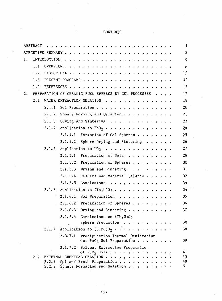

95
v
27 CRITERIA FOR PROCESS SELECTION AND SCALE-UP
271 Scale-up of Sphere Fabrication 95
272 Feed Preparation 95
273 Sphere Formation and Gelation 97
274 Washing 98
275 Drying 98
276 Sintering 98
28 REMOTE APPLICATIONS 98
281 Significant Engineering Scale Demonstrations bullbull bull bull 99
28-2 Engineering Design and Operational Concepts bullbullbullbullbullbullbullbullbullbullbullbullbullbull 100
283 Identification of Potential Operating Difficulties bullbullbullbull bull bull bull bull 102
29 REFERENCES bullbull 103
3 -FABRICATION OF FUEL RODS BY SPHERE-PAC TECHNIQUES bull bull 111
31 PACKING THEORY 111
32 EXPERIMENTAL RESULTS bull bull 114
33 LOADING EQUIPMENT AND METHODS 118
331 Vibrational Input bullbullbull 119
bull e- bull bull332 Fuel Sphere Blending and Loading 122
333 Compaction Aids bullbullbullbullbull 124
334 Postloading Procedures 124 ~-
34 ROD INSPECTION bull bull 126
341 Dimensional Inspection 126
342 Density Homogeneity Assay and Fuel Column Length bull bull bull bull bull bull bull 127
343 Impurity Analysis 129
344 Weld Integrity 129
35 PROCESS SCALE-UP CONSIDERATIONS 129
351 Sphere-Pac Loading 131
352 Fuel Handling 132
36 REMOTE APPLICATION 134
37 REFERENCES bullbullbullbull 135
vi
4 IRRADIATION PERFORMANCE OF SPHERE-PAC FUELS 141
4 1 IRRADIATION OF THERMAL REACTOR FUELS 141middot middot middot middot middot middot 41 1 Studies at ECN Petten Netheriands 141middot 412 Studies at Riso Denmark 155middot middot middot middot 4 1 3 Studies at KFA Juich FRG bull 156
414 -Studies at CNEN Rome Italy 157middot middot middot middot middot middot middot middot 415 Assessment of Tests to Date 159middot middot
42 THERMAL REACTOR IRRADIATIONS OF FAST
middot middot middot middotREACTOR OXIDE FUELS 160
421 Studies at ORNL 160middot middot middot middot middot middot middot middot middot 422 Studies at Karlsruhe FRG 170
43 REFERENCES 170middot middot middot middot middot middot middot middot middot 5 STATUS AND RECOMMENDED FUTURE WORK 173
51 SOL AND BROTH PREPARATION 173middot middot middot middot middot middot middot middot 511 Status 173middot middot middot middot 512 Future Work 174middot middot middot middot middot middot middot middot middot
52 FORMING AND WASHING OF GEL SPHERES 175
521 Status 175middot middot middot middot 522 Future Work 176middot middot middot middot middot middot middot middot
53 DRYING OF GEL SPHERES 176middot middot middot middot middot middot 531 Status 176middot middot middot middot 530 2 Future Work 176middot bull middot middot middot middot bull
54 CALCINING AND SINTERING 177bull middot 541 Status 177middot middot bull middot middot middot middot middot middot middot bull middot middot middot middot 542 Future Work bull 177middot middot middot middot middot middot
55 CHARACTERIZATION OF SPHERES 178~ bullmiddot middot 551 Status 178middot middot - middot middot middot middot middot 552 Future Work bull 178middot middot middot middot bull middot middot bull middot middot bull middot middot bull middot
56 SPHERE-PAC LOADING AND ROD INSPECTION 179middot middot middot middot 561 Status 179middot bull 562 Future Work 179middot bull middot middot bull middot middot bull middot middot
57 IRRADIATION PERFORMANCE 180bull middot middot middot middot middot bull middot bull 571 Status 180
572 Future Work bull 180middot middot bull bull middot bull bull middot middot bull bull bull bull middot bull middotmiddot bull
vii
58 SCRAP RECYCLE 181
581 Status 181
582 Future Work 181
59 IN-PLANT WASTE TREATMENT 181
591 Status 181
592 Future Work bull 182
510 COMMERCIAL FACILITY 182
5101 Status 182
5102 Future ~Jork bull 182
511 REFERENCES 183
r
GEL-SPHERE-PAC FUEL FOR THERMAL REACTIONS ASSESSMENT OF FABRICATION TECHNOLOGY AND IRRADIATION PERFORMANCE
Compiled by R L Beatty R E Norman and K J Notz
ABSTRACT
Recent interest in proliferation-resistant fuel cycles for light-water reactors has focused attention on spiked plushytonium and 233U-Th fuels which will require remote refabrishycation The gel-sphere-pac process for fabricating metal-clad fuel elements has drawn special attention because it involves fewer process steps and fewer mechanically intensive steps than pellet technology all operations deal with either liquids or microspheres which are free-flowing and relatively dust-free These fabrication process characteiistics should also enable lower personnel exposures during both fabrication and maintenance operations
Gel-sphere-pac fabrication technology involves two major areas the preparation of fuel spheres of high density and loading these spheres into rods in an efficiently packed geometry Gel sphere preparation involves three major steps preparation of a sol or of a special solution (broth) gelation of droplets of sol or broth to give semirigid spheres of controlled size and drying and sintering these spheres to a high density Gelation may be accomplished by water extracshytion (suitable only for sols) or ammonia gelation (suitable for both sols and broths but used almost exclusively with broths) Ammonia gelation can be accomplished either extershynally via ammonia gas and ammonium hydroxide or internally via an added ammonia generator such as hexamethylenetetramine Sphere-pac fuel rod fabrication involves controlled blending and metering of three sizes of spheres into the rod and packing by low- to medium-energy vibration to achieve about 88 smear density these sizes have diametral ratios of about 40101 and are blended in size fraction amounts of about 60 coarse 18 medium and 22 fine
In addition to fabrication process advantages irrashydiation test results available to date indicate that sphereshypac fuel performs at least as well as pellet fuel and may in fact offer an advantage in significantly reducing mechanical and chemical interaction between the fuel and cladding
From the standpoint of overall process complexity and economics it should be noted that the normal feed for gel sphere preparation heavy metal nitrate solution is the usual
Chemical Technology Division
I
2
product of fuel reprocessing so that fabrication of gel spheres performs all the functions performed by both conver~ sion and pellet fabrication in the case of pellet technology
In view of the apparent and potential advantages of gelshysphere~pac fuel an assessment of the state of the art of gel-sphere-pac technology was undertaken to provide a sound basis for further development While considerable further development work is required the flexibility of the gelshysphere-pac process in relation to both fabrication of advanced and alternative fuels and fuel performance suggests that con~ tinued development for tWR application is well justified
EXECUTIVE SUMMARY
Recent interest in proliferation-resistant fuel cycles has focused
attention on fuels that will require remote refabrication after reproshy
cessing The gel~sphere-pac process involves fewer process steps and
fewer mechanically intensive steps than pellet technology all operashy
tions deal with either liquids or microspheres which are easily handled
in a dust-free manner For example gel-sphere preparation replaces the
p6wder~conversion step (carried out at the reprocessing plant for pellet
flowsheets) However the dense spheres once prepared are directly
usable for loading fuel rods In comparison pellet flowsheets require
powder pretreatment pre~slugging and pelletizing before the usable
fuel form is obtained These fabrication benefits will also lead to
lower operator exposures during both fabrication itself and during
maintenance
in addition to these fabrication benefits data available to date
show that sphere-pac fuel may give superior performance in-reactor
Therefore an assessmertt of the state of the art for the gel-sphere-pac
proceSs was undertaken to provide a sound basis for further development
of the technology It should be noted that the normal feed for gel~ sphere-pac heavy metal nitrate solution is the normal product of
reprocessing and therefore gel-sphere-pac performs all the functions
performed by both conversion and refabrication in pellet technology
3
Gel-sphere-pac technology involves two special characteristics
the preparation of truly spherical particles of high density in all
necessary sizes and loading these spheres into rods in an efficiently
packed geometry by low- to medium-energy vibration (Note that the
latter operation distinguishes sphere-pac from vi-pac which uses parshy
ticles of any shape and very high-energy compaction) Gel sphere preshy
paration involves three major steps preparation of a sol or of a
special solution (broth) gelation of droplets of sol or broth to give
semi-rigid spheres and drying and sintering these spheres to a high
density Gelation may be accomplished by water extraction (suitable
only for sols) or ammonia gelation (suitable for both sols and broth
but used almost exclusively with broths) ammonia gelation can be
accomplished either externally via ammonia gas and ammonium hydroxide
or internally via an added ammonia generator such as hexamethy1enshy
tetramine Sphere-pac requires three sizes of spheres to achieve a
smear density approaching 88 these sizes have diametra1 ratios of
about 40101 The preferred method at this time from a fabrication
viewpoint is to incorporate all the fissile content in the two large
sizes which allows the fines to be made in a separate operation using
only fertile isotopes - the so-called fertile fines method However
the sphere-pac process is not limited to use of fertile fines and all
three sizes of spheres can have the same composition If a lower denshy
sity is acceptable two sizes will yield about 85 smear density
A discussion of development needs is conveniently organized along
two standards the scale of operation and the various functional
systems involved For processes aimed eventually at the design
construction and successful operation of a commercial facility that
requires remote (shielded hot cell) handling the following sequence is
both realistic and representative of the actual number of development
stages required
Cold Lab to demonstrate process feasibility using nonradioactive
stand-ins
Hot Lab to verify process feasibility using radioactive
materials
4
Cold Engineering to demonstrate equipment concepts under nonshy
radioactive conditions
Hot Engineering to verify equipment concepts under remote
radioactive conditions
Cold Prototype to demonstrate full-scale components including
integrated andor remote operation for the more
complex steps
In general cold lab work provides the basis for both hot lab and cold
engineering work while the latter two together provide the basis for
both hot engineering and cold prototype work while these two provide a
solid basis for a commercial-scale facility Fuel samples for irrashy
diation testing would normally be produced during all stages of developshy
ment In the above sequence gel-sphere-pac development is largely
through cold lab and is getting started on both hot lab and cold engishy
neering A small amount of hot engineering was done in the past and
because of criticality limitations some components are already at proshy
totype scale (but not at prototype sophistication) Some irradiation
testing has been done both in the US and in Europe with test rods
and some full-length rods with generally favorable results additional
tests are under way in the US and abroad
From a functional point of view gel-sphere-pac development may be
divided as follows
gelation process includes three options
- water extraction
- internal chemical precipitation
- external chemical precipitation
droplet formation
washing and drying
calcination and sintering
sphere characterization
waste treatment
sphere-pac loading of rods
inspection of loaded rods
scrap recycle
5
The gelation processes developed at ORNL during the 1960s were
based on water extraction of sols of thoria urania plutonia and
various mixtures thereof and were very successful for product
microspheres up to about 600 [Jm in diameter (larger for some
compositions) However this process had difficulties with urania parshy
ticularly with sizes greater than 600 [Jm and the chemical gelation proshy
cesses developed in Europe are preferred These processes use ammonia
to cause a rapid gelation by the fast precipitation of ammonium diurashy
nate using various organic additives for gel support andor other purshy
poses Both internal and external gelation can yield urania and uraniashy
plutonia spheres over 1200 [Jm in diameter Chemical gelation is also
suitable for thoria-based compositions From scouting tests at ORNL we
prefer internal chemical gelation over external gelation Additional
work must be done to optimize both compositions and conditions to
design and test engineering-scale equipment and to carry out hot lab
tests
Droplet formation is well-understood and performed routinely at the
lab scale for all required sizes For the larger sizes a pulsed
laminar-flow nozzle is used both here and in Europe It provides
excellent size control and acceptable throughputs design and testing of
remotely operable systems are still required For the smallest size
(fines) a turbulent two-fluid nozzle is used and gives adequate
throughput but a broader size spectrum than desired The present
approach is acceptable but an improved method is desirable
The requirements for washing and drying are reasonably wellshy
understood and are being met successfully but largely in batch operashy
tions Continuous procedures need to be designed and tested The
requirements for the three sizes vary somewhat particularly for the
fines During these steps the handling procedures change from hydraulic
transport to gravity or pneumatic transport and equipment amenable to
this interface ~ust be tested
Calcining and sintering are being done succesfully on a batch
basis yielding product about 98 of theoretical density However conshy
siderable development is still required to understand and optimize these
6
processes for all the heavy metal compositions of interest Scale-up
will require equipment for continuous operation andor larger batches
while providing the necessary atmosphere control residence time and
uniformity
Considerable technology has been developed for sphere characshy
terization as part of the HTGR Fuel Recycle Program Contact or glove
box techniques have been developed for the determination of particle
density size shape composition crushing strength and microstrucshy
ture However a need still exists for techniques applicable to the
fines and for more rapid methods of chemical analysis
No direct development work has been done on waste treatment but
the needs have been identified and reasonable processes are known to
exist or are under development for other programs The conventional
wastes - such as discarded organic liquids discarded equipment and
decontamination solutions - can be handled by methods used by other
recycle programs The major waste ammonium nitrate can be handled by
either of two methods catalyzed decomposition in molten salt or regeshy
neration and recycle of ammonia and nitric acid For organics such as
urea and hexamethylenetetramine the preferred treatment is internal
recycle but suitable processes still need to be developed
The sphere-pac process for loading a fuel rod involves vibratory
packing of carefully sized spheres of the proper size ratio
Considerable technology has been developed regarding the identification
of proper sizes size ratios and blending ratios and loading sequences
to produce maximum smear densities and minimum loading times Sphereshy
pac loading of commercial-length fuel rods remains to be demonstrated
Simultaneous loading of all three size fractions shows promise of overshy
coming the problem of excessive loading times for long rods Much of
the particle dispensing and blending technology developed for HTGR fuels
is applicable
Significant development is required to enable economic inspection
of fuel rods with acceptable precision accuracy and speed although
most of the development is required for remote inspection regardless of
whether the fuel rod is fabricated from pellet or gel-sphere-pac fuel
7
Compared with pellets scrap recycle in gel-sphere-pac is a much
smaller problem since sphere dimensions are not as critical as are
pellet dimensions Any defective spheres can be recycled after drying
before sintering to density while dissolution is still relatively easy
Very little effort to date has been directed toward planning and
analysis of an integrated commercial refabrication plant based on gelshy
sphere-pac technology Concepts for gel-sphere-pac processes and equipshy
ment are rapidly progressing to the point where meaningful evaluation
can and should be performed
A thorough irradiation test program needs to be planned and
inaugurated as soon as possible since performance is the crucial item
in the final acceptance of gel-sphere-pac from both commercial and
licensing aspects In terms of total time licensing will probably be
the controlling factor and performance data are need~d
Although not a part of this assessment it should be mentioned that
by the addition of carbon during the gel sphere fabrication step carshy
bide microspheres can be made for use as an advanced fuel in fast reacshy
tors The gel-sphere process is also one of the preferred methods to
make HTGR fuel kernels Thus the process is highly versatile and
applicable to all ceramic-fueled reactors In addition pellets can be
fabricated from calcined spheres in addition to the technical benefits
deriving therefrom this approach has the benefit of yielding a fuel
form that is already licensed However this report deals only with the
fabrication of oxide sphere-pac fuel rods for thermal reactors
1 INTRODUCTION
The objective of this report is to provide a current comprehensive
assessment of US and foreign gel-sphere-pac technology pertinent to
light-water reactor oxide fuels The gel-sphere-pac route for fabricashy
tion of fuel rods is an alternate to the conventional pellet method
Gel-sphere-pac technology is not new but is currently receiving emphasis
for a variety of reasons described later With the gel-sphere-pac
process high density ceramic fuel spheres ofmiddot controlled sizes are
produced and these are subsequently loaded with the assistance of
low-energy vibration into the fuel rod cladding
11 OVERVIEW
Gel-sphere technology is applicable to fuel rod fabrication in
several ways as indicated schematically in Fig 11 bull Oxide spheres can
be used directly for sphere-pac loading of both LWR and fast reactor
fuel rods By the addition of carbon during the sphere fabrication
step carbide microspheres can be made for use as an advanced fuel in
fast reactors The preceding are traditional applications of gel
spheres More recently their possible use for the fabrication of
pellets has been investigated in addition to the technical benefits
deriving therefrom this approach has the benefit of yielding a fuel
form that is already licensed This report will deal only with the
fabrication of oxide spheres and their incorporation into sphere-pac
fuel rods In addition to the applications shown in Fig 11 both
oxide and carbide spheres are suitable feed for HTGRs in which they are
coated with pyrolytic carbon and silicon carbide and then imbedded in a
graphite matrix this application requires spherical particles
Gel-sphere preparation is based on three major steps (1) preparashy
tion of a sol or of a special solution (broth) (2) gelation of
droplets of sol or broth to give semirigid spheres and (3) drying and
sintering these spheres to a high density Gelation may be accomplished
by two methods water extraction (suitable only for sols) and ammonia
gelation (suitable for both sols and broths but used almost exclusively
with broths) Ammonia gelation can be accomplished either externally
9
-----------------
10
ORNL-DWG 78-9912R2
r NITRATE SOLUTION OF I I
U TH ltU TH) J (U PU) (TH PU) I
I I
FABRICATION OF GREEN SPHERES I Ibull BROTH (OR SOL) PREPARATION
bull DROPLET FORMATION AND GELATION I bull WASHING AND DRYING I
r- - - - - -- - - - - -f- - -1 I
DENS IFICATION I REACTION SINTERING CALC INATI ON (FOR OXIDES) I (FOR CARBIDES) (OF OXIDES)
L_ -1 I
I FOR SPHERE-PAC I FOR SPHERE-CAL
I Ibull
ROD LOADING I PELLET FABRICATION bull BLEND I bull PRESSING bull LOW-ENERGY bull SINTERING
VIBRATION I ________ J
ROD LOAD ING I
Fig 11 Application of Gel-Sphere Technology to Fuel Rod Fabrication~ The portion inside the dashed line is addressed in this report
11
via ammonia gas and ammonium hydroxide or internally via an added ammoshy
nia generator such as hexamethylenetetramine internal gelation is
followed by treatment with ammonium hydroxide to complete the reaction
Sphere-pac requires three sizes of spheres to achieve about 88
smear density These sizes must have diametral ratios of about 40101
The actual diameters currently favored are 1200 300 and 30-50 Jlm The
preferred method at this time is to incorporate all the fissile content
in the two large sizes which constitute about 80 of the total mass
This allows the fines to be made in a separate operation using only fershy
tile isotopes - the so-called fertile fines method However the
sphere-pac process is not limited to use of fertile fines and if
required for accountability or other reasons all three sizes of spheres
can have the same composition If a lower density is acceptable two
sizes will yield about 85 smear density
Together the use of gel spheres and sphere-pac involves two speshy
cial characteristics (1) the preparation of truly spherical particles
of high density in all necessary sizes and (2) loading these spheres
into rods in an efficiently packed geometry by low-energy vibration A
generalized equipment flowsheet is shown in Fig 12
ORNL~OWG 1euroH4974R
NITRATE FEED SOLUTIONS SPHERE FORMING ~-roRMjNG AND GELATION lIQUlD
SPHfAE INSPECTION
~SPE
~~ o
PNEUMATIC TRANSFER
Fig 12 Gel-Sphere-Pac Process
12
The original interest in ge1-sphere-pac derived primarily from two
factors (1) the improved handling procedures possible with liquids and
free-flowing spheres over the powder-pellet method (see Fig 13) and
(2) the versatility of the gel-sphere processes in being able to handle
U Th Pu and mixtures thereof
ORNL-DWG 78-5676
LIQUID U Pu Th BROTH SPHERE WASHING
TRANSFER NITRATE PREPERATION FORMATION
and
PNEUMATIC SINTERING CALCINING DRYING TRANSFER
TO WELDING ETC
Fig 13 Gel-Sphere-Pac Fabrication Employs Liquids and Free-~ Flowing Solids which can be Handled in Closed-Pipe Systems
Other fabric~tion benefits are (3) the dust-free operati~ns involved
which are cleaner and result in less operator exposure (4) simpler
mechanical operations which are more amenable to remote operation and
maintenance (5) lower sintering temperature because the small
crystallites produced in the gels sinter more easily to a high density
and (6) easier conversion of mixtures to solid solutions than with
powders
In addition to the above fabrication benefits sphere-pac also proshy
vides potential performance benefits in that less fuel-cladding interacshy
tion has been observed in experiments done so far
1 2 HISTORICAL
The gel-sphere concept was invented by the catalyst industry over
20 years ago while sphere-pac was conceived at ORNL sometime later
Sol-gel sphere-pac technology was vigorously pursued in the-US until
June 30 1972 At that time the uS fast breeder reactor program
concentrated on pellet fuel and government support for particulate fuel
for breeder reactors was terminated The state of the technology at
that time was thoroughly reported in program and topical reports in
13
1-3symposia proceedings and in the complet ion report middotfor the breeder
fuel project referred to above 4 At that time US attention focused
on the preparation of urania sols that were gelled by water extraction
while European labs were looking at the chemical gelation of solutions
of uranyl ion sphere handling techniques were still relatively
unsophisticated
Since 1972 particulate fuel technology has been advanced on two
fronts First sol-gel development of UOZ (ThU)OZ and Th02 continued
as a part of the US and European efforts to develop fuels for the
High-Temperature Gas-Cooled Reactor Extensive progress was made
regarding sphere formation processes control of sphere size and sphere
handling transport and inspection 5 6 Also breeder reactor and
light-water reactor development efforts in England Germany Italy
Switzerland and the Netherlands have contributed significantly to gelshy)
sphere-pac technology for both oxides and carbides European achieveshy
ments were most notable in three areas (1) improvements in processes
to produce large spheres of UOZ by the use of uranium (VI)gel support
via added organics and chemical gelation by precipitation with ammonia
(Z) continuation of irradiation testing and (3) application of the carshy
bide route to UPu for fast reactors Most of the recent foreign work
has not been reported in the open literature
A related but distinctlydifferent loading method called vi-pac
has also been used In this process irregular fragments or ~hards of
ceramic fuel material are loaded into fuel rods and compacted by means
of high-energy vibration Shards were originally made by sol-gel proshy
cessesapplied to bulk materials (ie spheres were not formed) This
approach was successfully used to fabricate 1000 fuel rods 7 but did not
have the full benefits of sphere-pac - notable ease of handling dustshy
free operation and low-energy packing However a major incentive
even at that time was to avoid making pellets under remote conditions
and it was this requirement for thorium fuel cycles that prompted the
early work in sol-gel technology~8 Vi-PCiC fabrication is being pursued
again using crushed high-density UOZ but this work is directed to
possible benefits in performance during irradiation in powerreactors
14
and will be supplanted by sphere-pac fuel when the spheres are
available 9 High-energy vibration has also been used with spheres where
the smallest sizes were not free flowing but again the full benefits
of sphere-pac were not realized even though high densities were
attained and good irradiation performance was achieved IO
13 PRESENT PROGRAMS
The renewed us interest in gel-sphere-pac in 1977 came from two
directions the concern over nonproliferation-type flowsheets which
pointed toward fully remote refabrication and the desire for improved
fuel-cladding behavior to allow more severe thermal ramping during reacshy
tor operation
This report was prepared with funding from the Department of
Energy Division of Nuclear Power Development under its Fuel
Refabrication and Development (FRAn) Program which is administered by
Battelle Pacific Northwest Laboratories and is directed towards lightshy
water reactors II A similar study but directed towards advanced
(breeder) reactors was also done at ORNL for DOE Division of Reactor
Research and Technology (RRT)I2 The FRAD program is supporting a major
gel-sphere-pac development effort at ORNL which has been under way
since June 1977 RRT is supporting several sm~ller programs at ORNL
aimed at providing the basis for a gel-sphere-pac demonstration
The HTQR Recycle Development Program6 which has supported work on
the fabrication of spherical particles for many years is currently
funding work on the preparation of dense microspheres of mixed UOz-UC2
which will be required for the medium-enriched flowsheets proposed under
various nonproliferation scenarios Previously HTGRs used highly
enriched uranium for the fissile fraction and the reference recycle
flowsheet used a resin process to prepare these microspheres which are
a mixed oxide-carbide of-intermediate- density
The Fuel -Performance Improvement- Program9 administered by
Consumers Power Co for DOE-NPD is testing several alternative fuel
forms including sphere-pac ORNL is providing dense urania
microspheres to Exxon Nuclear Company where fuel rods are being fabri shy
cated for irradiation in the Halden and Big Rock Point reactors
15
14 REFERENCES
1 Sol-Gel Processes for Ceramic Nuclear Fuels~ (Proc Panel Sponsored
by IAEA Vienna May amp-10 1968) International Atomic Energy
Agency Vienna 1968
2 R G Wymer and A L Lotts Co-chairmen Symposium on Sol-Gel
Processes and Reactor Fuel Cycles (Proc Symposium Sponsored by
ORNL Gatlinburg Tenn May 4-7 1970) CONF-700502
3 Sol-Gel Processes for Fuel Fabrication (Proe Panel Organized by
IAEA Vienna May 21-24 1973) IAEA-161 International Atomic
Energy Agency Vienna 1974
4 A L Lotts Comp Fast Breeder Reactor Oxide Fuels Development
Final Report ORNL-4901 (November 1973)
5 P R Kasten General Chairman Gas-Cooled Reactors HTGR and
GCFBR~ (Proe American Nuclear Society Topical Meeting Gatlinburg
Tenn May 7-10 1974) CONF-740501
6 A L Lotts and P R Kasten Gas-Cooled Reactor Programs~ HTGR
Fuel Cycle Development Program Annu Prog Rep Sept 30 1977
ORNL-5423 and earlier reports (Thorium Utilization Program) in
this series
7 C C Raws J L Matherne F W Miles and J E Van Cleve
Summary of the Kilorod Project A Semiremote 10 kgday Demonstration
of 233U02-Th02 Fuel Element Fabrication by the ORNL Sol-Gel
Vibratory-Compaction Method ORNL-3681 (August 1965)
8 R G Wymer Coordinator Thorium Fuel Cycle (Proc Int Symp
Gatlinburg Tenn May 3-6 1966) CONF-660524 r
9 C E Crouthamel Comp~ Fuel Performance Improvement Program
QuarterlyAnnual Progress Report April-8eptember 1977 Exxon
Nuclear Co Report COO-4066-4 (November 1977) and earlier reports
in this series
10 JRN Verheugen Comp Postirradiation Examination of Mixedshy
Oxide Vibrasol Fuel Pins Fourth Semi-Annual Report (January-June
1977) ECN-77-122 (August 1977) and earlier reports in this series
16
11 Battelle Pacific Northwest Laboratory The Technical Program Plan
for the Department of Energys Puel Refabrication and Development
Program (in preparation)
12 W J Lackey and J E Selle Camps Assessment of GeL-Sphere-Pac
Puel for Past Breeder Reactors~ ORNL-5468 (October 1978)
2 PREPARATION OF CERAMIC FUEL SPHERES BY GEL PROCESSES
Ceramic fuel sphere preparation by gel processes has been under
development for almost 20 years The concept known as the sol-gel
process originated in the US where active development was pursued
until 1972 At that time the US fast reactor program concentrated on
pellet fuel and the government dropped support for sol-gel However
several foreign countries continued gel-sphere preparation are presently
quite active in this area and have made significant contributions to
gel-sphere technology
Throughout this gel-sphere development period three basic processes
emerged each dependent on a different approach to achieve sphere gelashy
tion These processes are
1 water extraction gelation - developed at ORNL in the US
2 external chemical gelation - developed at SNAM Progetti in Italy
3 internal chemical gelation - developed at KEMA in the Netherlands
The basic steps in each of these processes are generically the
same These are sol or broth preparation sphere formation and gelashy
tion washing (for internal and external gelation only) and drying
calcining and sintering However as described in Sects 21 through
23 different methods are used to accomplish each step Water extracshy
tion gelation uses an organic alcohol to dehydrate droplets of sol until
they solidify (gel) External chemical gelation uses either gaseous or
dissolved ammonia to externally gel droplets of broth Internal chemishy
cal gelation uses the formation of ammonia (as a decomposition product)
to internally gel droplets of f~ed
Water extraction gelation was developed for reactors requiring fuel
spheres no larger than 600 ~m Very little development has been focused
on the large sphere-pac size (gt800 ~m) However this process appears
impractical for such large spheres (ie 600 ~m represents an upper
limit for the applicability of this process) However water extraction
may have some advantages in preparing the fine laquo100 ~m) sphere-pac
fraction The other two processes (external and internal gelation) on
the other hand have been demonstrated to have advantages in preparing
the large fraction All the processes have been used to prepare the
medium coarse (200-350 ~m) sphere-pac fraction
17
18
The following sections of this report describe in detail the three
gel processes for preparing ceramic fuel spheres the current status of
each process flowsheet step is presented equipment experience with
scale-up and remote application is described and the research and deve~
lopment needed to bring gel-sphere technology to a state where commershy
cialization can be carried forth are presented In these discussions
you will note that water extraction is discussed in significantly
greater detail than both internal and external gelation This situation
arises because the ORNL staff (having developed this process) has a much
greater depth of knowledge of this process than could be acquired for
the other two processes from the literature and personal communication
21 WATER EXTRACTION GELATION - P A Haas
For this type of sol-gel process the liquid drops are converted to
solid spheres by extraction of water by an organic liquid The
colloidal particles of the sol are concentrated until they become
unstable and gel The water extraction processes (including compatible
sol preparation procedures) were invented or developed at the Oak Ridge
National LaboratoryI2 Water is removed by mass transfer across the
phase boundary and the rate of gelation is determined by the rate of
mass transfer Since external gelation requires mass transfer of chemishy
cals (usually NH3 or NH4+) external gelation and the water extraction
process share similarities and problems that do not occur for internal
gelation which does not depend on mass transfer In addition most of
the development for the water extraction gelation process was directed
at reactor concepts requiring fuel spheres no larger than 600 ~m This
sphere size represents an upper limit for its applicability
In general terms the water-extraction sol-gel processes for preshy
paring high-density oxide spheres require the following three principal
operations
1 preparing an aqueous oxide sol
2 dispersing the sol as drops into an organic fluid usually
2-ethyl-l-hexanol (2EH) which extracts water from these drops to
give solid gel spheres
19
3 drying and sintering at controlled conditions to remove volatiles
promote densification and reduce or convert chemically as necessary
A continuous sol preparation process was developed for (ThU)02
but other sol preparation processes were batch operations Gel spheres
were formed in continuous column systems while drying and sintering
were batch processes
It is important to recognize that the characteristics of a sol or
gel depend on the conditions used to prepare it and that effects of a
change of conditions are difficult to predict Sols and gels are not at
thermodynamic equilibrium and their properties are not fixed by a comshy
bination of conditions that would fix a system at equilibrium As a
result of the nonequilibrium states the process requirements must be
given in the form of recipes that are dependable for producing the
desired products
The second of our general sol-gel process operations the formation
of gel spheres may be further divided as follows
1 dispersion of the sol into drops each of which contains the amount
of oxide that will be present in a sintered sphere
2 suspension of the sol drop in an organic liquid usually 2EH while _
water is extracted to cause gelation
3 separation of gel microspheres from the forming liquid
4 recovery of the organic liquid for reuse
These four parts of gel sphere formation are carried out in continuous
column systems The first and third operations are similar for all solshy
gel processes for preparation of spheres The formation of liquid drops
is reviewed separately (Sect 24) and the separation of gel spheres
will be mentioned briefly as part of specific sphere formation or drying
procedures Recovery of the organic liquid for recycle will be menshy
tioned separately for each sol composition
20
211 Sol Preparation
The sol is the most important variable for operation of any sol-gel
process A sol is thermodynamically unstable and cannot be uniquely
specified by any practical combination of chemical and physical measureshy
ments Therefore any generalized discussion of the effects of sol
variables is qualitative With these qualificationsthe discussion in
this section considers the generalized effects important to
understanding the sol-gel process including limitations and problems
Detailed or specific preparation procedures are reviewed later in the
specific sections for each composition of product
Gelation by extraction of water requires that the sols be stable
aqueous dispersions of well-crystallized oxides Low concentrations of
- nitrate peptize all the nuclear fuel materials Most feed purification
or fuel reprocessing processes give nitrate solutions as the products
and nitrate in the gel spheres decomposes during high-temperature sinshy
tering without leaving any undesirable residues
All the sol preparation processes reported in the following secshy
tions start with nitrate solutions Uranium and plutonium may require
adjustments to the optimum valence~ while thorium is only tetravalent
The true sols result from growth and dispersion of colloidal oxide
crystallites All the true sols are basically four-valent that is
Th02_ Pu02 and U02 dispersions The procedures for conversion of the
nitrate solutions to colloidal oxide sols are of the types listed below
All these have been applied to thorium plutonium(IV) and uranium(IV)
unless otherwise noted
1 Precipitation of hydroxides with NH40R washing out NH4N03 and pepshy
tizing with RN03
2 extraction of RN03 with liquid amines and hot digestion to grow
crystallites by condensation
3 bull hydrothermal denitration to oxide then peptization of the oxide
mixed with R20 by residual or added RN03 [this is not practical for
U(IV) as it oxidizes to U(VI)]
21
4 slow addition (partial neutralization) of NH40H with digestion to
grow oxide crystallites dispersed at pH of 2 to 4 While stable sols
can be prepared with the NH4N03 present gelation by extraction of
watec is practical only for low NH4N03 concentrations
Each sol preparation procedure has advantages and disadvantages
The precipitation processes are simplest on a laboratory scale but are
difficult to scale up The solvent extraction of HN03 involves liquids
throughout without any handling of precipitates solids or slurries
The hydrothermal denitration gives a usable nitrate waste
(HN03 solution) The pH adjustment with ammonia gives no waste and is a
simple process but the subsequent removal of the NH4N03 is troublesome
and produces a waste product The solvent extraction and the pH adjustshy
ment procedures can start with Th(N03)4-U02(N03)2 solutions (and proshy
ba9ly Th-Pu or U-Pu nitrate solutions) to give mixed sols while the
other two procedu~es cannot Individually prepared sols can be simply
mixed to give mixed oxide sols if both the colloidal dispersions remain
stable at the mixed conditions
212 Sphere Forming and Gelation
After a sol drop is formed it must remain suspended until sufshy
ficient water is extracted to produce a relatively dry gelled sphere
A gel surface that is in equilibrium with unsaturated 2EH (not saturated
with H20) is generally smooth and nonsticking thus the gel spheres can
be drained dried or handled The settling velocity of the spheres
increases as water is extracted Settling is affected more by the denshy
sification of the gel particles than by the decrease in size due to
removal of H20 In the continuous operation of a fluidized gelation
column the higher settling velocity is used to preferentially remove
gelled product spheres from the column
Problems related to fluidization are encountered when sol drops or
incompletely gelled spheres (1) ~oalesce to give large drops (2) stick
to the column and cause large accumulations on the walls or subsequent
releases of large clumps or (3) cluster into clumps without coalescing
22
Large drops or clumps that are formed as a result of these problems have
higher settling velocities than the usual product gel spheres and conshy
sequently will fallout of the column before gelation is complete
Another fluidization problem involves the failure of the sol drop
to remain in the column until gelation is complete Perfect fluidization
is not possible thus the conditions that allow discharge of the gel
product spheres also occasionally allow discharge of incompletely gelled
spheres Since the settling velocity depends partially on the diameter
of the drop and the average residence time required for gelation varies
inversely with its size a disperser that forms sol drops of uniform
size should be selected The discharge of a small quantity of incompleteshy
ly gelled particles can be tolerated If the surface of a particle is
gelled any water remaining in the core may diffuse to the 2EH and in
turn to drier gel particles If the incompletely gelled particles conshy
tain sufficient water to reform a sol drop or to give a sticky surface
they will adhere to and ruin adjacent particles
To form good spheres conditions must be selected so that mass
transfer of the water in the organic liquid outside the drop is
controlling and therefore must be slower than the mass transfer of water
in the sol drop If the mass transfer is too rapid the outside of the
drop will gel quickly and then crack or distort as water is extracted
from the liquid core Organics that have a high solubility for water
tend to have low interfacial tensions with the sol and thus allow
distortions of the sol drop Surface-active compounds in the organic
can greatly reduce the coalescence or sticking of sol drops but they
lower the interfacial tensions
The gelation by extraction of water generally requires wel1shy
crystallized sols of low nitrate-to-metal ratio High nitrate conshy
cent rations in the sols consistently increase distortion clustering
and sticking problems and also increase cracking during drying and sinshy
tering of the gel spheres Sols that are less well crystallized appear
to gel at lower concentration and then crack as removal of water is
completed
23
213 Drying and Sintering
After the extraction of water is completed ltthe gel spheres wet
with 2EH (or other organic) must be dried and sintered The weight loss
is less than 02 g per gram of metal oxide (Th02 U02 Pu02) and most
of this material (alcohol H20 N03-) is removed by volatilization below
220degC The chemical gelation processes give gel spheres with ov~r 10
times as much material to remove and some components (NH4N03 organic
polymers) cannot be removed by drying
The treatment of the gel spheres following water extraction conshy
sists primarily of slowly heating from room temperature to 1150 to
1550degC depending on composition with a purge gas to remove fumes and
vapors densification is then completed during several hours at the peak
temperature In practice the required conditions are more complex and
must meet one or more of the following requirements
1 Gels containing U(IV) must be protected from oxidation by an
inert atmosphere until densification is completed
2 Products containing uranium must be treated with H2 at 1150degC
(usually Ar-H2mixtures for safety) to complete the reduction to U02
3 Gels f9rmed in 2EH should be dried in a steam atmosphere to
220degC to promote removal of 2EH If this treatment is omitted the chemshy
ically bound 2EH can cause rapid heating and cracking if burned out
with air or give excessive carbon in the product if not burned out
4 Since the gel is not washed to remove nitrate high nitrate in
the sol can result in rapid heat generation and cracking of the gel
The presence of both u(Vr) and organic in the gel makes drying of
high-nitrate gels very difficult
5 Carbon remaining in the calcined product can result in
incomplete densification For Pu02 U03-U30S or Th02 the carbon can
be burned out by using an air purge above 220degC For U(IV) sols and
U02 gels steam andor C02 will aid removal of carbon without excessive
oxidation of the uranium
24 shy
214 Application to Th02
Thoria gives the most stable sols the strongest gels and the
simplest process chemistry since Th(IV) is the only significant valence
Therefore most of the sol-gel process variations can be applied to
thoria Thoria sols have been prepared by the four procedures listed in
Sect 211 Thoria sols have also been prepared by precipitation of
thorium oxalate washing thermal decomposition and peptization of the
Th02 with RN03 Any of the Th02 sols with low nitrate content can be
formed into gel spheres by extraction of water
The processes developed at ORNL to prepare Th02 spheres use
middot i d i f 1 i 34h yd rothermaI den1trat on 1n a rotary en trator or so preparat on
The conversion of thorium nitrate to a dispersible Th02 powder must be
carried out under conditions that minimize the decomposition of nitrate
into nitrogen oxides The desired overall reaction is
When this hydrothermal denitration is continued until the residual
nitrate in the Th02 is less than 01 mol per mole of the thorium the
Th02 can be almost completely dispersed (more than 99 often 999)
When improper conditions are used a large fraction of the Th02 cannot
be dispersed even though ahemieat anatyses and aommon physieat measupeshy
menta ape identiaat with those of the dispepsibte Th02
The following three requirements are critical in the preparation of
dispersible Th02
1 Local overheating and the thermal decomposition of thorium
nitrate must be carefully avoided
2 Superheated steam must be supplied throughout -the temperature
range 200 to 400degC to favor the hydrothermal reaction Denitration with
a deficiency of water gives a~ undispersible Th02 product
3 The denitration conditions should favor desirable types of N-Oshy
Th bonding the pres~nce of 02 (or air) for temperatures up to 250degC
appears to favor the preferred bonding
25
Fluidized-bed denitration appears to be an excellent method for
avoiding local overheating and for providing good contact with
superheated steam plus air A 025-m-diam (la-in) fluidized-bed
denitrtor was operated5 to produce dispersible Th02 at the rate of
45 kgh (100 lbh) The Th02 product was carried out of the reactor with
the gases and collected on a filter This product which was dispersed
by agitation with hot water was excellent for the preparation of
high-density Th02 fragments However the residual N03-Th ratios were
higher than the optimum mole ratio (011) for a sol prepared from a
hydrothermal denitration product The Th02 sol produced from a sample
of fluididized-bed product was not suitable for preparation of spheres
the gel spheres cracked into fragments as frequently occurs with highshy
nitrate sols Higher temperatures andor longer residence times in the
fluidized bed would probably yield a product having a lower N03-Th mole
ratio and hence more desirable for use in preparing spheres Other proshy
cess variations such-as holding the thorium nitrate feed at the boiling
point and using some air with the fluidizing or atomizing gas might be
favorable since such variations could affect the N-O-Th bonding
2141 Formation of Gel Spheres
Only the process conditions receive detailed discussion here The
design and operation of the fluidized-bed sphere-forming columns have
been reported elsewhere 6
Surfactants are added to the gelation column to prevent coalescence
of drops clustering or sticking of the gel spheres to the column
walls Although Span 80 is more effective than Ethomeen S15 Span 80
alone or in high concentrations tends to cause a wrinkling or raisin
type of distortion 6 High Ethomeen S15 concentrations although less
objectionable may cause a dimple distortion or contribute to drying
difficulties The overall approach for Th02 spheres is to add Ethomeert
S15 and Span 80 in weight ratios of at least 4 to prevent clustering or
coalescence and to avoid the distortions attributed to Span 80 alone
26
The water content of the 2EH affects the rate of gelation A low
water content requires high flows of 2EH through the still to remove
water Generally used still flow rates are 100 to 150 times the flow
rate of the sol so that the steady-state water concentration of the
2 EH is between 10 and 15 vol
2142 Sphere Drying and Sintering
Drying and sintering of the Th02 spheres involve some complex physshy
ical and chemical changes The density of the gel spheres is less than
40 of that of the sintered spheres they must lose up to 15 of their
weight after discharge from the sphere-forming column Energy changes
are detected by differential thermal analyses of gel spheres as
endothermic peaks 7 The volatile constituents include water nitrate
2EH and surfactants As a preliminary treatment to drying with heat
air may be blown (or drawn by vacuum) down through the bed of gel
spheres to remove much of the 2EH and perhaps some water
The overall drying-sintering schedule starting with gel spheres
from which gross amounts of 2EH had been removed was as follows
Drying
1 argon flow from 25 to 100degC for 1 to 16 h
2 argon plus steam flow from 110 to 220degC for 6 to 24 h
3 argon plus steam flow at 220degC to give a total of 20 to 30 h with
steam
Sintering
1 air atmosphere to SOOdegC at 100degCh
2 air atmosphere from 500 to 1150degC at 300degCh
3 air atmosphere at 11S0degC for 4 h
4 cooldown in air at rates of 05 to 20degCmin
The purpose of the drying operation is to remove volatiles (1) at
rates that do not cause cracking during drying and (2) completely
enough that burning in air during the sintering of Th02 does not cause
cracking of spheres The argon atmosphere is necessary since the parshy
tially dried gels can ignite at surprisingly low temperatures (as low as
150degC for pure Th02 gels and 110degC for other compositions) A high
27
nitrate content in the sol and U(VI) if present lower the autoignishy
tion temperatures and act as oxidizing agents which can cause exoshy
thermic reactions even in the absence of air The ThOZ spheres prepared
from hydrothermally denitrated ThOZ powder are the least troublesome
sol-gel spheres to dry and sinter spheres smaller than 300 ~m can
be dried and sintered without the use of steam As the sphere diameter
increases the use of steam at the higher temperatures becomes more
essential if cracking is to be avoided Sintering in air burns out the
remaining carbon so that low carbon contents do not depend on the steam
stripping
Most of the drying and sintering times given above were selected to
allow heat and mass transfer through beds of spheres and are much
longer than the requirement for a single sphere or a thin layer of spheres
The short times were determined for 1 kg of Th02 in small glass dryers
while the long times were for IS to 30 kg in larger dryers Sintering
was performed in alumina crucibles containing up to 5 kg of Th02 each
215 Application to U02
Since neither U(VI) nor U03 gives stable oxide sols the initial
step for preparing low-nitrate uranium sols is reduction to U(IV)
At least five flowsheets were used to convert the uranous [U(IV)]
nitrate solutions to U02 sols based on both the precipitation with ammoshy
nia and the extraction of RN03 by liquid amines Three problems are
common to all the flowsheets
1 The U(IV) is oxidized to U(VI) by 0Z nitrate or other mild
oxidizing agents and the sol properties become poor as the fraction of
uranium present as U(IV) is reduced to 08 or less
Z Digestion is required to grow amorphous U02 to more
crystallized UOZ which is necessary for higher uranium concentrations
and lower N03- concentrations in a fluid stable sol
28
3 Troublesome properties occur during intermediate stages of the
sol preparation Very poor settling and filtering behavior cause difshy
ficulties for the NH40H precipitation and washing Thioxotropic gels
can be formed at intermediate nitrate concentrations for the amine
extraction of RN03
The first difficulty is minimized by the combination of three
procedures (1) adding formic acid to complex the U(IV) and make it
less sensitive to oxidation by nitrate (2) blanketing all processJ
operations with argon or nitrogen to eliminate oxygen and (3) limiting
the temperatures and times for digestion As a result of the second
difficulty batch processes gave much betterU02 sols than continuous
processes The batch process conditions can be controlled to give a
complex sequence of conditions that are not practical for a continuous
process The batch processes also allowed selection of process conshy
_ditions to minimize the third problem The final versions of both the
precipitation and the amine extraction processes gave good U02 sols
The amine extraction process appeared to be much more practical for
scale-up to larger capacities and for remote operations and therefore
only the batch amine extraction process is described in detail
The engineering-scale demonstration of preparation of U02 spheres
by water extraction was limited to nonfluidized column operation only
Larger UOZ spheres were prepared in fluidized-bed columns as described
for Th02 spheres but long-term recycle of 2EH was not practical
Therefore about 200~m UOZ spheres (sintered diameter) were the largest
practical
2151 Preparation of Sols
To describe the preparation of U02 spheres two one-week demonstrashy
tion runs will be discussed 8 The 1 M ~rania sols used in the
demonstration runs were prepared by the Concentrateu Urania Sol
Preparation (CUSP) process in which a 10 to 14 M crystalline urania
sol is produced directly by solvent extraction The handling of solids
which was required in some earlier urania sol processes is avoided
29
while the sol concentration step inherent in the earlier solvent extracshy
tion process for the preparation of dilute sols9 10 is eliminated or
minimized Further this process lends itself to closer control than
can be imposed easily on the previous processes In general sols preshy
pared by the CUSP process show greater reproducibility and have longer
shelf lives than urania sols prepared by other solvent extraction
methods
Sol preparation time which varies from 35 to 4 h is independent
of batch size since nitrate must be extracted for prescribed periods of
time Various precautions must be taken during sol preparation For
example the first nitrate extraction should require a minimum of 90
min to allow time for the proper release of nitrate otherwise the
N03-U mole ratio of the sol product will be too high even though the
conductivity is in the proper range However care must be taken not to
prolong the first nitrate extraction excessively since thickening or
possibly gelation can result from overextraction During the second
extraction favorable oxidizing conditions are present (elevated temshy
perature and release of NO) consequently to minimize the oxidation of
U(IV) to U(VI) this extraction while sufficiently long to ensure
complete crystal1ization~ should not be unnecessarily extended
Following sol preparation the sol and solvent are drained separateshy
ly and the equipment is washed out successively with dilute HN03 (~3 M)
and with water Some solids accumulate at the solvent-sol interface
primarily during the crystallization phase These solids tend to cling
to the equipment during draining resulting in a loss of uranium to the
equipment wash solution equivalent to approximately 2 to 4 of the urashy
nium in the feed solution and a loss to the solvent wash (dilute HN03)
of approximately 05 The uranium can be recovered from these acidic
wash solutions
Some uranium is lost to the solvent primarily during the first and
second nitrate extractions This loss which amounts to approximately
05 of the uranium in the feed is in the form of entrained sol and is
present as a colloidal suspension The particles are well dispersed
carry a slight negative charge cannot be removed by filtration or
adsorption on silica gel or activated carbon and are not effectively
removed by the standard solvent treatments
30
2152 Preparation of Spheres
Compared with earlier demonstrations the major differences in the
week-long demonstrations of U02 sphere preparation were the use of sol
prepared by the CUSP process and the formation of spheres in a
nonfluidized column In addition the column height was 85 m (28 ft) 11 vs the 3-m (lO-ft) column of earlier work and the temperature of the
2EH was 50 to 80degC in the nonf1uidized column (vs 25 to 35degC for the
fluidized columns) Initial experience with CUSP sols showed that
recycle of 2EH was very troublesome Therefore recycle of the 2EH was
a principal point to be demonstrated In the week-long runs 2EH was
successfully recycled
The principal limitation with regard to the nonfluidized preparashy
tion of spheres is that the sol drops introduced into a nonfluidized
column must be small enough to gel before they settle to the bottom
The required column heights depend on mass transfer and on the settling
ve1OC1ty 1nton as nvest1gate an corre ate mass trans er as amiddot C1 12 hi d d 1 d f
function of sol drop size and organic liquid variables The settling
velocities may be calculated with Stokes equation or a drag coefshy
ficient Both the sol drop size and the density vary with time Thus
mass transfer and the settling velocity also vary with time and analyshy
tical solutions are not possible However the time and free-fall
distance as a function of sol drop variables and alcohol variables can
be conveniently calculated
Heated 2EH is supplied to the top of the column and the temshy
perature decreases down the column as heat is lost to the surroundings
This temperature gradient is favorable since it gives rapid extraction
of water at the top where the sol is fluid and slower extraction at
the bottom where gelation occurs An 85-m (28-ft) column requires a
2EH temperature of 80degC to prepare 210-~m fired spheres from aIM
U02 sol
31
2153 Drying and Sintering
The overall drying-sinter~ng program starting with gel spheres wet
with 2EH was as follows
Drying
1 argon flow from 25 to 110degC for I to 2 h
2 argon plus steam flow at 110 to IS0oe for about 4 h
3 argon plus steam flow at ISOoe overnight
Sintering
1 to 500degC at 100 oeh in argon
2 over the range 500 to I1S0oe at 300 oeh in argon
3 at 1150 0 e for 4 h in Ar-4 H2
4 over the range 1150degC to ltIOOoe for gt36 h in argon
The purpose of the steam was to promote removal of organic substances
and thus avoid leaving excessive carbon in the sintered spheres From
05 to 1 g of steam was used per gram of U02 Although the higher temshy
peratures with steam are more effective for carbon removal they tend
to make the U02 gel become more reactive and more sensitive to oxidashy
tion Therefore 180degC was chosen as the maximum temperature to minimize
difficulty with oxidation during the transfer from the drying equipment
to the sintering furnace The Ar-4 H2 reduces uranium oxides to
D02 for the temperatures employed The long cool-down was characshy
teristic of the furnace however faster cooling as high as 20degCmin or
higher would not affect the spheres Use of an oxygen-free atmosphere
was necessary during cooling because any 02 present would oxidize the
V02 The dense U02 spheres were not reactive with air below IOOdegC
The drying and sintering equipment consisted of small laboratoryshy
scale batch units The product collectors and dryers were Pyrex vessels
fabricated from 600-ml filter funnels with coarse-porosity filter frits
These dryers were placed in a laboratory oven and connected both with an
argon supply and with steam from a distillation flask Sintering was
performed in alumina crucibles in a commercial muffle furnace that had
been modified to allow improved atmospheric control
32
2154 Results and Material Balances
The size distributions of the calcined spheres produced during a
demonstration run is shown in Table 21 The nonfluidized
sphere-forming column was operated continuously The production rate
for the run was approximately 29 kg u02d
Table 21 Size Distribution of U02 Spheres Produced During Nonfluidized Column Demonstration Runa
Proportion 9lt in Each Size Range (11m)0
Batch lt125 125-149 149-177 177-210 210-250 gt250
1 118 67 758 57 007 003 2 147 71 734 45 009 009 3 144 74 685 93 03 015 4 153 90 675 81 01 5 179 86 656 76 02 009 6 101 54 742 102 01 7 103 72 716 106 02 007 8 133 76 677 103 06 04 9 117 66 713 99 05 01
10 97 71 646 163 07 16 11 124 66 707 98 03 02 12 147 135 671 44 01 01 13 97 71 791 40 14 108 191 559 133 08 01
Total weight g
15424 10202 83562 10665 358 252
of grand total 128 85 694 89 03 02
- - 868
aOne glass two-fluid nozzle [033-mm-ID (0013-in) sol feed capillaries] was used sol flow rate about 73 emsmin No vibration
33
Some of the chemical and physical properties of the calcined
spheres are as follows density 97 to 100 of theoretical OU ratio
2003 to 2005 roundness ratio (D D) 102 to 103 carbon con-max mln tent 24 to 60 ppm and iron content 12 to 46 ppm The size control
was good for a nonvibrating nozzle The standard deviation for run 2
was about 10 There was very little surface porosity as indicated by
the small surface area (8 to 400 m2kg) and the low gas release (4 cm3kg)
The dried and calcined spheres (see Fig 21) were round and cracking
and surface imperfections did not represent a problem
Fig 21 Spheres of U02 (a) Gel spheres dried at 170degC in steam-argon (b) Spheres calcined for 4 h at 1130degC in Ar-4 H2
Because of the nature of the operation of the nonfluidized
sphere-forming column essentially no uranium was lost However some
waste 27 and 22 wt was generated during the demonstration runs
This waste resulted from sphere samples dried in air for size and shape
examinations
34
2155 Conclusions
The following conclusions are drawn with regard to the preparation
of high-density U02 spheres from CUSP sols in a nonfluidized forming
column when hot 2EH is used as the dehydrating agent
1 The U(IV) feed can be routinely prepared in a batch slurry
uranium reductor Vigorous agitation is required for a uniform reducshy
tion and completion of the reduction can be determined by monitoring
the redox potential bull
2 CUSP is an instrumented batch process for preparing 10 to 14 M
U02 sols that are fully crystalline and have U(IV) concentrations of 85
to 87 Reproducible sols can be prepared in relatively simple equipshy
ment by following the standard operating procedure Some uranium is
lost to the organic solvent a loss also occurs as the result of equipshy
ment cleanout between batches Uranium in the waste solutions can be
recovered easily The sol yield varies from 92 to 98
3 The operation of the nonfluidized sphere-forming column was
quite satisfactory at about 3 kg U02d Although the production capashy
city of the 100-mm-ID (4-in) column has not been establi~hed it is
greater than 3 kg U02d Some difficulty was encountered with plugging
of the glass two-fluid nozzle capillaries however this was greatly
minimized by installing a glass frit filter in the sol line The 2EH
was recycled and good-quality round spheres were prepared by smallshy
periodic additions (~O1 vol ) of Span 80 Two additions were needed
during the demonstration runs An on-stream factor of 96 was attained
for each run
4 The feasibility of the CUSP nonfluidized column process for the
preparation of high-density medium-size U02 spheres has been
demonstrated and the process can be adapted to commercial use
216 Application to (ThU)02
Three sol preparation processes were used with water extraction for
gelation of (ThU)02 spheres These were
1 Mix Th02 sol from hydrothermal denitration (Sect 214) with
U02 sols (Sect 215) These sols can be mixed in all proportions
35
The mixed sols have the behavior and limitations of U02 with some
improvement toward the properties of Th02 for Thu gt 4 For Thu lt 10
it is adequate to assume that the limitations and results already
described for U02 sols apply and this approach will not be discussed
further
2 Add U03 or uranyl nitrate to Th02 sols prepared by hydrothermal
denitration This is suitable for ThUratios greater than 10 The
U(VI) has a significant effect on the behavior of the sol and these
sols have gelation behavior and limitations similar to Th02-U03 sols
that are prepared by an amine extraction process
3 Extract with a liquid amine The gelation procedures and
results for the third method are also applicable to the mixture of
Th02 sol with U03 or uranyl nitrate above the limit of ThU gt 10 For
the preparation of Th02-U03 sol by amine extraction gelation by extracshy
tion of water was practical for Thu gt 3 Lower ratios were more dif shy
ficult with some useful results for ratios of 2 to 3 Method 3 is
discussed in detail below
2161 Sol Preparation 13 14 The preparation of ThO~-U03 sols by the amine extraction process
consists of extracting nitric acid from a dilute solution of
thorium-uranium(VI) nitrates with a secondary amine (Amberlite LA-2) to
form a dilute Th02-U02 sol that is about 03 M in heavy metals (Th + U) The dilute sol is then concentrated to greater than 1 M by evaporashy
tion of water to give a product that is suitable for use in forming
spheres In the work presented here a dilute sol having a Thu atom
ratio of 425 was evaporated to 16 M (Th + U) It was very fluid at
this concentration The preparation of the dilute sol by the amine
extraction process and the regeneration of the amine were carried out
continuously for 10 d producing an 81 Th0Z-19 U03 sol at the rate of
104 kg(Th + U)d The dilute Th(N03)4-U02(N03)2 feed solution was
prepared and the dilute sol concentrated in batch processes at rates of
preparation that kept pace with the continuous operation of the amine
36
extraction equipment The results demonstrated the feasibility of the
continuous operation of the amine extraction process and confirmed that
a reproducible sol product could be obtained
2162 Preparation of Spheres
In the sphere-forming process gel spheres are produced as water
is extracted from droplets of a given sol by 2EH The droplets are
fluidized by an upflowing stream of 2EH until they gel The settling
velocity of the spheres increases as the water is extracted Proper
selection of the fluidizing velocity of 2EH allows preferential removal
of gelled product and permits continuous operation
The addition of surfactants to the 2EH is required to stabilize the
spherical shape of the sol droplets during water extraction Two surshy
factants are used in combination to facilitate the formation of ThOZ-U03
gel spheres Span 80 and Ethomeen S15 The proper concentrations of
nitric acid and water are also necessary to obtain a spherical gel proshy
duct If proper concentrations were not maintained during operation of
the forming column gel particles that are cracked distorted
clustered or surface-pitted are produced
Past experience largely involving the preparation of ThOZ spheres
has shown that the periodic addition of surfactants to the 2EH gives
satisfactory results for continuous operation of sphere-forming columns
The rate at which the additions are made is established empirically
from visual observations of particles in the column and from microscopic
examination of the product
The sol is dispersed into droplets that are released into the 2EH
at the enlarged top of a tapered fluidization column A throughput of
10 kg(Th + U)d was achieved by using a multiple two-fluid nozzle
disperser and a flow rate of 18Z cm3min for the 164 M (Th + U) sol
Eleven nozzles produced sol droplets 900 to 1500 ~m in diameter A
diameter shrinkage factor of 3 occurs from sol droplet to the calcined
sphere for a high-density (ThU)02 product prepared from a 164 M (Th +
U) sol
37
The column circuit used in the study presented here had been used
over a period of several years and had proved to be effective for proshy
ducing spheres in the 200shy to 600-~m-diam (sintered) size range 6 This
column and all the equipment in the column circuit can be readily
adapted to remote operation
2163 Drying and Sintering
A steam atmosphere was used as the purge gas in the drying operashy
tion because it effectivly removed imbibed and sorbed organic
materials and suppressed exothermic reactions 7 Exothermic reactions of
a magnitude sufficient to cause excessive breakage of the spheres
occurred evenwith steam if a uniform temperature was not maintained
throughout static beds of spheres
Operation of the sintering furnace was entirely satisfactory
Sintering-dependent specifications of particle density carbon content
content of absorbed gases and OU atom ratio were met
To remove carbon and densify the dried spheres were heated in air to
11S0degC They were then reduced at 1150 0 C in Ar-4 H2 for 4 h to attain
the desired OU atom ratio The reduced fuels are cooled to room temshy
perature in argon
The products had densities of 95 to 98 of theoretical 20 to
40 ppm C and OU atom ratios of 2001 to 2020 The products were
solid solutions of U02 in Th02 as determined by x-ray lattice parameter
measurements These gels had a good shrinkage pattern for ease of remoshy
val of the remaining volatiles The density was only about 40 of
theoretical at 850degC and all the pores were open Thus the sorbed
carbon-bearing materials nitrates and water could easily be removed
before pore closure occurred The reducing gas flowed through the parshy
ticle bed rather than across the top This gave suitably low values for
carbon content and OU ratio
38
2164 Conclusions on (ThU)02 Sphere Production
1 Good-quality spheres can be prepared by using either the conshy
tinuous or the batch method of surfactant control
2 The continuous method for controlling the surfactant conshy
centration in the sphere-forming column is definitely superior to the
batch addition method
3 Operation with the multiple two-fluid nozzle unit which conshy
sists of 11 nozzles is entirely satisfactory however a multiple-orifice
gravity-type disperser has performed satisfactorily in other tests and
should also be applicable for this type of operation
4 Yields of 90 to 95 for 250- to 450-Wm-diam product spheres can
be expected from the sphere-forming process at the current level of
development Control of the mean diameter size in the 300- to 400-~m-diam
size range can be attained to plusmn3 of the specified diameter
5 The forming drying and firing operations in the preparation
of spheres appear adaptable to remote operation The column circuit is
sufficiently developed to allow immediate adaptation
217 Application to (UPu)02
All sols for preparing UPu)02 spheres were made by blending
UOZ and Pu02 sols The UPu ratios were greater than 1 and the gelation
and drying requirements were essentially those described for UOZ sols in
S~ct 215 Therefore only the PuOZ sol preparation is described in
detail While PuOZ sols are more difficult to prepare than Th02 sols
the stability and ease of sphere preparation for PuOZ sols are similar
to those for ThOZ sols The most completely demonstrated process for
Pu02 sols is a combination of precipitation and thermal denitration A
more recently developed liquid extraction of RN03 as important advanshy
tages and should be developed further for future applications Both sol
preparation procedures will be described
39
2371 Precipitation Thermal Denitration for Pu02 Sol Preparation
Figure 22 presents the generalized flowsheet for preparing plutoshy
nia sol (The digestion step shown was not used initially) This is a
flexible flowsheet as shown by the ranges of concentrations over which
it has been demonstrated the batch size given is 150 g Pu Before preshy
cipitation a feed adjustment is made if necessary by passing NO gas
through the Pu(NO)4 solution to convert both Pu(VI) and Pu(III) to the
desired Pu(IV) Most Pu(N03)4 solutions do not require a plutonium
valence adjustment A minimum HN03 concentration of 1 M is maintained
in the feed to prevent polymerization however sols have been successshy
fully prepared starting with free HN03 concentrations as high as 3 M
In the precipitation step as little as 48 excess NH40H has proved to
be satisfactory as long as the concentration of this base in the final
solution was at least 1 M The Pu(N03)4 feed solution is added to the
NH40H solution at rates up to 30 cm3min Moderate agitation is used
to ensure rapid neutralization and precipitation of the Pu(OH)4 The
solution of NH4N03 and excess NH40H is drawn off through a filter having
10-~m-diam openings The precipitate is washed four times to remove
NH4+ the filter cake is resuspended in each wash Filtration time is
about 30 min per wash Plutonium losses to the total filtrate have been
less than 001 Af~er the washing step the precipitate is digested
for 2 h in H20 at 95 to 100degC this treatment stabilizes the crystalline
structure and prevents depolymerization during subsequent steps A
high-nitrate sol is then formed by peptizing in dilute RN03 at a N03-Pu
mole ratio of approximately 2 All the steps including peptization are
carried out in a single precipitation-filtration vessel 020 m (8 in)
in diameter with a porous stainless steel filter in the bottom The
high nitrate sol passes through the bottom of the vessel leaving no
solids on the filter
A N03-Pu mole ratio of 1 or greater is necessary to accomplish
peptization Although ratios as high as 4 have been demonstrated a
ratio of 11 is sufficient to produce a sol upon heating to approxishy
mately 90degC At this point a true sol (crystallite size lt 20 nm)
exists but spheres formed from this material would have a low density
40
ORNl Dwg 67-7214
Pu(N03)4 FEED H20 WASH H20 ADDITION NITRATE
I 150 g Pu 12 liters 22 liters ADDITION
1-3M HN03 3 literswQsh 18 -63 M HN03
bull 41-115 9 Pu Iliter
bull PRECIPITATION FI L TER-WASH DIGESTION PEPTIZATION
25-63 MNH40H 4 washes 2 hrs at 95-1000 C 20-53 g Puliter
iIM NH40H ofter Coke volume = - I 2 liters NOPu 13 25
reaction Agitate at -90 0 C
I FILTRATE
I 7 liters
Transfer to evaporator
H20 ADDITION
05 liter
EVAPORATION DENITRATION RESUSPENSION = Drain to Concentrate to Dry and heatdenitration vessel Agitate
1-2 ttl Pu at to 240 0 C 05 liters
102 0 C 3-6 hrs 300 9 Puliter
t CONDENSATE PuOZ SOL
~4 liters NO IPu 01-02
Fig 22 Generalized F10wsheet for Preparing Plutonia Sol
41
and a low resistance to crushing To form a desirable product a sol
must have a N03-Pu mole ratio in the range from 01 to 02 the
appropriate reduction in ratio is accomplished by thermal denitration
Several other methods of precipitation and denitration were attempted
however none produced satisfactory results
In the thermal denitration step the sol is evaporated to dryness
at 100degC to form a thin porous cake that remains intact through subshy
sequent heating to 240degC Excess RN03 evolves during evaporation
giving an initial N03-Pu mole ratio of 08 to 10 in the dry solid
In general after 1 to Z h at 240degC this ratio decreases to OZ to 03
usually an additional 2 to 3 h is required to attain a final N03-Pu
mole ratio of 01 to 015 Progress of the denitration is followed by
periodically resuspending a weighed sample of the dry material and
titrating with NaOH to determine the N03- content It is important that
the heating of the solid be uniform in order to produce a homogeneous
product Denitration that is allowed to proceed until the N03-Pu mole
ratio is appreciably less than 01 yields a form of Pu0Z that cannot be
resuspended The design of the denitration vessel allows independent
control of temperatures of the top and bottom surfaces and limits radial
gradients to about ZoC
The denitration step promotes crystallite growth and agglomeration
After denitration the average size of the crystallites is approximately
8 nm these crystallites form agglomerates as large as 100 nm Though
crystallite growth is desirable the degree of agglomeration must be
limited if a stable sol is to be obtained Denitrated sol having a
N03-Pu mole ratio in the range of 01 to 015 can be resuspended in
water with only mild agitation to form sols having plutonium conshy
centrations approaching 2 M more concentrated sols may be produced by
~ubsequent evaporation if desired
2172 Solvent Extraction Preparation of Pu02 sols
A solvent extraction process for preparing Pu02 sols was
developed IS The process (see Fig 23) has three major operations
1 extraction of HN03 from Pu(N03)4-HN03 feed with a long-chain
alcohol such as n-hexanol until a plutonia sol with a N03-Pu
mole ratio of about 1 is obtained
42
2 seeding in which sol is added to the feed solution before or during
extractionto create a micelle structure of aggregated crystallites
3 thermal denitration which consists of drying and baking the sol
ORNl DWG 71-6175 RI
FEED
01 - 015 ~ III(N034- 05-10 ~ HNO
9 (VOLUME RATIOS)
EXTRACT WITH n-HEXANOl
TO A NOj MOLE RATIO
OF 09 EXTRACT WITH n-HEXANOl
TO A N03 MOLE RATIO
OF 09 EXTRACT WITH n-HEXANOL
TO A NOj MOLE RATIO
OF 09
EVAPORATE TO DRYNESS AND HEAT AT 230C FOR
IS MIN TO GROW CRYSTALLITES
1-2~~ SOL
01-02 NOfPu MOLE RATIO
Fig 23 Solvent Extraction Process for the Preparation of Low-Nitrate Plutonia Sol
The aggregated micelle structure promotes rapid denitration and
crystallite growth because these sols denitrate very rapidly and are
insensitive to overheating denitration can be accomplished by a variety
of continuous processing methods As a result low-nitrate sols
(N03-Pu mole ratio from 01 to 02) with average crystallite diameters
of 60 to 70 nrn are easily prepared The sols can be mixed with urania
or thoria sols in any proportion and used to prepare spheres These
sols therefore have all the versatility of application of sols preshy
pared by earlier methods In addition considerable advantages are
obtained with regard to method of preparation and ease of scale-up
43
The process flowsheet shown in Fig 23 employs continuous
extraction with n-hexanol during which the feed solution is added
incrementally at the indicated volume ratios With this procedure the
effect of double seeding is obtained in a single run because extraction
is continued after each feed addition until colloidal plutonium polymer
is formed Following the final extraction to a N03-Pu mole ratio of
08 to 12 the sol is evaporated to dryness and heated for a minimum of
15 min at 230degC in a dry sweep gas to remove volatile decomposition proshy
ducts The final sol is prepared by resuspending the denitrated solids
in water and evaporating to the desired plutonium concentration Sols
with plutonium concentrations in excess 0f 2 M and having N03-Pu mole
ratios between 01 and 02 are obtained by the process
The extraction apparatus used for the small-scale (20 g Pu) labora~
tory preparation of plutonia sols consists of two identical
contactor-separator sections In the first (or extraction) section
nitric acid is extracted from the aqueous Pu(N03)4 solution with
n-hexanol After separation of the phases the alcohol is pumped to the
second (or stripping) section where the acid is stripped from the alcoshy
hol into water The regenerated alcohol is then recycled to the extracshy
tor The plutonium nitrate solution is circulated through the
extraction section only and the water strip is circulated through the
stripping section only The net result of this extraction-stripping
cycle is to transport HN03 from the plutonium nitrate solution to the
water strip which can be either changed periodically to maintain satisshy
factory extraction rates or processed continuously to remove extracted
plutonium by cation exchange and HN03 by anion exchange The progress
of the extraction is monitored by a conductivity probe located in the
circulating plutonium nitrate stream Further description of this proshy 1 bl 15cess 1S ava1 a e
Before denitration the sol must be dried This was typically
accomplished by evaporation at 80 to 10QoC however it should be
possible to perform this step by nearly any desired method since the
sol can be boiled if desired and the evaporation rate is not critical
The N03-Pu mole ratio of the sol before concentration to dryness is a
44
critical variable the optimum value is in the range of 08 to 10
Lower values of about 06 or less result in plutonia solids that will
not resuspend in water after thermal denitration while higher values
increase the time required for denitration
The presence of water vapor had an adverse effect on denitration
behavior Crystallites from high-nitrate plutonia sol~ prepared by any
method undergo two growth mechanisms during thermal denitration at eleshy
vated temperatures One is crystallite growth which is desirable and
the other is irreversible random aggregation of crystallites which is
undesirable because of the production of large particles that frequently
will not resuspend to form a sol The formation of large particles is
readily detected in a sol by accompanying color change When the
crystallites are primarily unassociated the sol is dark green (nearly
black) As large particles form the color becomes much lighter In a
severe case the sol is nearly white and solids settle rapidly upon
standing
A series of tests was made to determine the effects of low nitrate
concentration and larger crystallite size on the stability of mixed
U02-Pu02 sol The shelf life of mixed sol prepared from low-nitrate
plutonia sol (N03-Pu mole ratio = 02 to 04) and CUSP urania sol was S
to 8 d at 2SoC This compares with a shelf life of only 30 min for
mixed sols prepared with high-nitrate plutonia sol (N03-Pu = 07) In
both cases reducing the temperature to about SoC greatly increased the
shelf life Because of the improved s~elf life a series of mixed-sol
(80 U02 20 Pu02) sphere-forming runs was made in which the sols were
not cooled to SoC as is required when high-nitrate p1utonia sol is
used Yields of 90 to 95 were consistently obtained in these experishy
ments Pure plutonia spheres were also readily prepared from low-nitrate
plutonia sols
A series of laboratory tests was made to demonstrate the formation
of spheres from mixed U02-Pu02 sols prepared from low-nitrate plutonia
sols Several mixed sols containing 80 U02 and 20 Pu02 were prepared
from two plutonia sols and two CUSP sols Good quality sintered spheres
were obtained in yields of 90 to 95 in eight consecutive experiments
45
Although these experiments were perfomed on a laboratory scale the
results indicate that spheres can be prepared by techniques that have
been demonstrated on an engineering scale for Th02 and Th02-U02 sols
22 EXTERNAL CHEMICAL GELATION - R D Spence
The external gelation technique has been called the gel-support
precipitation technique The original gel-support precipitation method
was the Italian SNAM process Though deve16Red in 1962 this method
was first published16 17 in 1970 The distiniuishing feature of this
method is that a water-soluble organic polymer i5 added to a heavy metal
solution or sol The polymer supports the particle spherical shape
while ammonia diffuses into the gel bead and precipitates the heavy
metal One of the most attractive features of the original method was
that no pretreatment of uranium solutions was required The necessary
chemicals were simply added to the uranium solution and the spheres
gelled A simplified flowsheet for the external chemical gelation proshy
cesses is shown in Fig 24 Figure 25 illustrates the process
flowsheet developed for continuous production using the SNAM process
ORHL own 1amp - 4921
METAL (U Pv Th) WAteR SOLUBLE POL (MERS NITRATE SOLUTIONS (METHYL CELLULOSE DERWATIVES
POLYviNYL ALCOHOL) AND OTHERS
OPTIONAL ADDITIVES (MM HOs bull UREA TETRAHYDROfURFURYL ALCOHOL)
NH
NHOM NH NO
ORGANIC
NH H03 NH-40H ANO ORGANICS
CONDENSATE AND GASES
AIR
AIR GASES
Fig 24 Simplified Flowsheet for External Chemical Gelation Process
l
46
ORNL-DWG 78-16548
WET SECTION DRY SECTION MICROSPHERE FORMATION HEAT TREATMENT
VERTICAL MOVING BED CALCINATION FURNACE
CONTINUOUS HIGH TEMPERATURE FURNACE
AGING WASHING COLUMN COLUMN
I
I - __ I ~TWO LIQUID PHASES L _ ~-~ c_ __J TRANSFER DEVICES
TRANSFER DEVICE
Fig 25 Flowsheet of the SNAM Process Based on G Brambilla et al pp 191-209 in Symposium on Sot-Get Ppoaesses and Reaatop FUet Cyates CONF-700502 (May 1970)
Although the Italians developed the SNAM process people at HOBEG and KFA-Julich in Germany and at Harwell in Great Britain use or used
1modified SNAM processes amp-23 Figures 26 and 27 illustrate the proshy
cess flowsheets developed by KFA for continuous production of thoriumshy
containing spheres Workers at KEMA in the Netherlands also used an
external gelation method but had difficulty producing particles greater 24 26than 100 ~m in diameter - Thus they prefer their internal gelashy
tion process In addition KFA people are ~orking toward elmination of 22 23 the water-soluble organic polymers Workers at General Atomic
Company (GA) in the United States use a proprietary external gelation 27 process f or sphere preparat10n
Hochtemperaturreaktor-Brennlement Gesel1schaft
---- - --- - --- ----
47
3 GAS
l I
I EXCHANGER I
I
t
I REJECTED SPI1poundRfS
I I I I
0WASTE
------shyWASTE WAHR II NMNO
I--shy ARGOIIiI WlfH
4- H2 WATER
Fig 26 F10wsheet of the KFA Precipitation Process Using Hexone Based on E Zimmer et a1 TPans Am NuaZ Soa 20 591-93 (1975)
ORNL-DWG 78-~6547
~L~~~~OFF-GAS SOL TANK NH3-GAS I
l VIBRATOR SPHERE I PREPARATION I JACKLEG GEL PARTICLE
SINGLE LAYER BELT DRYER 300middotC
HOLDUP SAMPLERTANK
WASTE WASHING WATER COLUMN
VIBRATORY FEEDER
I WASH WATER
t 7 NH3
Fig 27 Flowsheet of the KFA Precipitation Process Without Hexone Based on H D Ringel and E Zimmer TPans Am NucZ Soc 27 292-93 (1977)
48
The SNAM-type process development status was stated in the conclushy17shysions of a 1970 report
1 The main aspects which make the process particularly attractive are a The feed is a solution which must be neither reduced nor
denitrated b Spheres can be obtained with a nominal diameterchosen in
a wide range (150-1100 ~m) with low dimensional dispersion (plusmn 3)
c The U02 product density can be controlled in a wide range (70-98 TO) and high crushing strength values and oxygen-toshymetal ratios lower than 2005 are obtained
d The heavy metal losses in the different process steps are practically negligible
2 The process has been successfully tested on a pilot plant scale basis to produce any combination of thorium uranium and plushytonium oxide mixtures
3 A continuous production technique has been successfully estabshylished by direct and in glove-box operation of different pilot plants
4 The pilot plant operation is automatically performed and only a minor surveillance is therefore required
5 The know-how hitherto acquired on the pilot plant operation makes it possible to employ the pr9cess on an industrial scale basis
6 At the present development status the gel supported precipishytation process is economically competit~ve in comparison with other processes
The spherical shape is formed by dripping the sol or broth from a
capillary or flowing the sol or broth through a vibrating nozzle into
air or organic liquid Spherical drops form from the effect of surface
tension before exposure to the precipitating chemical Deformation may
occur at the gas-liquid interface or liquid-liquid interface This
problem has been handled successfully by exposing the droplet to ammonia
gas or dissolved ammonia thereby strengthening the surface of the
49
28sphere The British have developed a foam technique The foam is
formed qy bubbling ammonia gas into ammonium hydroxide and cushions the
impact as well as he1ping~harden the sphere
The SNAM process originally had some problems with sphericity 22 29 30 29twinning and sate111tes but the Italians practically elimishy
nated the latter two and improved their product sphericity to typical
values of 1 03
Another problem common to the SNAM-type processes was the presence
of organic compounds in the wet gel spheres The organic compounds
caused sticking during drying and cracking during calcining The 31 32problem was handled by use of surfactants during washing and dehydrat1ng
special calcining to decompose the organic compounds (porosity is essenshy 17 18 2(-23 33-36tia1 for escape of decompos1t10n gases) dissolution of
t hese compounds d wash1ng 23 or as ment10ne above e11m1nat10n 0fur1ng d 22 23 the organic compounds from the process
Although other users have produced fines with their variation of 37-39the SNAM process the Italians used theCNEN method to produce f1nes
The CNEN method uses a nitrate-extracting organic in the gelation step
to gel the sphere while removing the nitrate species After evaluating
both processes the Italians decided to try to develop the SNAM process 37-39to produce both coarse and fine part1c1es
221 Sol and Broth Preparation
As mentioned above no pretreatment was required for preparing the
uranium broth However the thorium was supplied as a sol and the plushy
tonium as Pu(IV) polymer although for low plutonium content the monoshy
meric form is acceptable Pretreatment to achieve the desired state
invo1yes denitration of thorium or plutonium nitrate Several denitrashy
tion methods are available and no preference is cited for one method
over another
50
In general the starting solution is the heavy metal nitrate If
necessary the nitrate solution is pretreated to form a sol Next the
organic polymer and other additives are added often as another solushy
tion These additives provide pH adjustment viscosity adjustment and
filler Besides the polymer a modifier is added to help adjust the
d40I d attac The iviscosity and protect t he po ymer f rom aci k Brit sh reporte
investigating a number of polymers (not named) and that each polymer has
a modifier associated with it According to the literature any polyshy
saccharide was suitable Four prerequisites were required for accepting
a polymer The polymer must
1 be water soluble and compatible with the high ionic content of the
sol or broth
2 thicken the sol or broth along with the modifer to enhance drop
formation but leave the solar broth fluid enough to achieve
reasonable flow rates through the nozzles
3 quickly form a gel structure to withstand impact at the aqueous
interface
4 form a gel structure strong enough to support the heavy metal in
the spherical shape until it solidifies then be capable of
debonding without damaging the inorganic structure
The polymers that have been used include hydroxypropyl methyl
cellulose (Methocel) polyvinyl alcohol (PVA) dextran natural gums
and starch derivatives (Wisprofloc) The modifiers and additives
include tetrahydrofurfuryl alcohol (TFHA) formamide urea ammonium
nitrate dioxane acetamide and glycine Three combinations of polymer
and modifier seem to have enjoyed the most success The original SNAM
recipe used Methocel and THFA the Germans have done most of their work
using PVA and various additives including urea and THFA and the British
have settled on a proprietary polymer and modifier
There are two exceptions to the above general description One
the Germans are working to eliminate the organic additives They use a
large excess of urea and ammonium nitrate and preneutralize by heating
to decompose the urea into ammonia and carbon dioxide Viscosity and pH
of the solution are very important parameters Two the British have
used utanium fluoride (which must be converted to uranyl fluoride) as a
starting solution 17 1841
51
222 Sphere Formation and Gelation
Drop formation was accomplished by dripping from a capillary or
needle by natural stream breakup or with a vibrating nozzle The
details of drop formation are covered in Sect 24 The original SNAM
process used a two-fluid nozzle with air and sol or broth as the two
fluids 16 The air flow rate ~long with the nozzle diameter controlled
the drop diameter Also the air flow kept ammonia from gelling the
solution on the nozzle and clogging the nozzle tip The drop formed its
spherical shape in air then passed through an ammonia gas layer which
hardened the surface into the final shape The drop then impacted the
aqueous ammonia surface the hardened surface retaining its shape The
drop quickly gelled as it settled to the bottom of the vessel in the
gelation solution (concentrated ammonium hydroxide) for aging All the
versions of the SNAM process follow this basic sequence drop formation
surface hardening interface impact and gel formation and aging in
aqueous ammonia Although the British do not use a two-fluid nozzle
they still form the drops in air followed by ammonia gas and conshy 22 28centrated ammonium hydrox1de In addition they have developed a
foam mentioned above to soften the impact and enhance surface hardening
The foam is formed by bubbling ammonia gas into concentrated ammonium
hydroxide that contains a surfactant
The Germans developed a process that differed in detail from the
original SNAM process Rather than a gaseous layer over the aqueous
ammonia an organic compound (methyl isobutyl ketone was used) conshy 20 22 31 32 42taining ammon1a (typically 015 M) was used Going
through the familiar SNAM sequence the drops are formed from a
two-fluid nozzle (vibration was not used) in ammonia-free ketone pass
into ammonia-containing ketone where the surface hardens impact the
aqueous interface and quickly gel in the aqueous ammonia The Germans
also developed a continuous process using a horizontal vibrating
nozzle 22 2336 The drops form in air followed by an ammonia gas
layer and drop a short vertical distance (30 mm) to a 1 aqueous
ammonia solution
52
223 Aging Washing and Dehydrating
The aging solution was generally the same solution as the gelation
medium aqueous ammonia (1-30) The aging time varied from several minshy
utes to overnight Generally when large-scale or continuous production
was being considered a time of 10 to 30 min has been considered long
enough
To prevent cracking on drying the salts (generally ammonium
nitrate) were washed from the wet gel beads Usually a dilute ammonia
solution was used to keep the heavy metals from repeptizing although 36distilled water has been used The last report from the Germans indishy
cates that they use 1 ammonia in the gelation stage as well as during middot A h hwash1ng surfactant was 1ntroduced1n t e wash1ng stage 313242 T e
HOBEG and NUKEM (Germany) processes used an isopropanol wash which not
only washed out the salts and the PVA (eliminating the need for thermal 20-22removal) but also dehydrated the wet gel beads
The Italians used azeotropic distillation to dehydrate their beads 16 17after washing w1th water Carbon tetrachloride was recommended
because of its nonflammabilitybull This method of dehydrating was also
designed for continuous production in pilot plants with capacities up to
30 kgd 17 43 The Italians preferred this method because it gave the
beads a more open porous structure important in calcining Also no
sticking occurred while dehydrating in an organic liquid Other methods
they found successful were air drying (at lOo-120degC) and vacuum drying
224 Drying
In the original SNAM method no details are given on drying organic
liquid from the azeotropic distillation before calcination although the 17spheres are clearly let free of the organic Most likely the carbon
tetrachloride does not wet the spheres very well so draining brief
exposure to air and good ventilation during the initial stages of heat
treatment are sufficient (It is important to remember that carbon
tetrachloride decomposes to form phosgene Therefore carbon tetrashy
chloride should be removed before high temperatures are achieved) As
53
mentioned in the previous section the Italians indicated that air
drying and vacuum dryingwere satisfactory for combining dehydration and
drying
Workers at KFA have developed a belt drier for continuously drying
(and dehydrating) the spheres in a monolayer at 250 to 300degC in 20222331323642 B f d i h h h d i ha1r e ore ry ng t e sp eres were was e w t a
surfactant The atmosphere in the dryer is kept at a minimum humidity
level to ensure controlled drying otherwise drying would be so rapid
that cracking would occur Even so drying is very rapid taking only
about 10 min After drying reabsorption can be so rapid that spheres
may absorb water and burst on cooling Therefore while the spheres are
at 160degC their water content must be equilibrated with that present at
room temperature The continuous process designed by the Germans has
the spheres going directly to a furnace from the belt drier eliminating
the burst problem
The HOBEG and NUKEM processes which dehydrated with isopropanol
used vacuum [53 kPa (400 torr) for HOBEG 67 kPa (500 torr) for NUKEM]
at elevated temperatures (80degC for HOBEG 100degC for NUKEM) to remove the 20-22isopropanol which could be recycled The NUKEM method took
several hours to dry the spheres of isopropanol
225 Calcining and Sintering
Heat treatment at temperatures around 500degC eliminates the organics
still present in the dry gel particles and converts the metals to oxide 16 17 33 34The Italians calcined at 450 to 550degC 1n a1r Harwell
calcined in C02 at SOdegCh to 800 to 850degC (held for 4 h)1841 HOBEG
calcined in air at 300degC The NUKEM process calcined at 300degC for 5 h
in air The KFA belt drier combines dehydration drying and precalci shy
nation at 250degC in 10 to 15 min
Sintering was performed in a reducing atmosphere at high temshy
peratures Generally the particles were sintered for a few hours in
hydrogen or Ar-4 H2 at temperatures ranging from 1200 to 2S00degC The
heating rates used ranged from 100 to 400degCh These sintering conshy
ditions led to greater than 95 of theoretical density (TD) for the
particles~
54
Both SNAM and NUKEM processes used air in sintering thoria 16 20 part1cles The KFA spheres could achieve 99 TD in 10 min at
1000degC but were sintered at 1300~C for several hours to produce a more
stable product 31 3236
226 Application to ThOZ
All the processes start with Th(N03)4 solution The SNAM process
preneutralizes 70 to 80 to Th(OH)4 by NH40H addition The resulting
sol is boiled 15 min cooled and mixed with the Methocel
solution 16 43 The final sol has 05 to 07 M Th and 5 to 10 kgm3
Methocel This sol is used to make ThOZ spheres by the SNAM process
described above The ThOZ spheres are sintered in air or an inert gas
to 1300 to 1350degC at 150 to ZOOdegCh to a density of 96-9816 Narrow
size ranges of plusmn3 are obtained for average diameters of 150 to
1000 Ilm~ 16 1733 Batc es 0 f 1 ogram s i ze have been produced ah kl 1n 1 b orashy
tory studies while several hundred kilograms have been produced in a 1735 hid f didcont i nuous pi1ot pant S ape separation s one a ter ry ng1 an
after sintering on the continuous system with less than 1 rejects in 17each case
35Harwell reported work on Th02 several years ago A viscous solushy
tion was formed by adding an organic polymer (usually Dextran) to a
Th(N03)4 solution This solution vas then formed into drops and precishy
pitated with ammonium or sodium hydroxide The Dextran was removed by
heating to ZSOdegC under vacuum Details were given for (ThU)OZ spheres
and will be given in Sect 228
The Thoria sol for the KFA process is prepared by treating
Th(N03)4 with ammonia gas 20 22Z3323642 The resulting precipitate
is stirred and heated to form the sol with 1 M Th The gel spheres are
formed by use of the two-fluid nozzle with a ketone overlayer described
above The spheres are washed with 05 M ammonia containing a small
amount of surfactant and dried in air at a controlled humidity (eg
40degC dew point) at ZOOdegC The dried spheres could be immediately sinshy
tered at 1200 to 1300degC (several hours) to produce 200 to 600-11m-diam
55
Th02 spheres at 99 TD The laboratory-scale unit using this process
produced 250 drops per second or 05 kg Thh (based on 475- m-diam
kernels)
In the process developed later by KFA the sol was formed in much
the same way However 2 to 3 M Th02 sol is used and viscosity is a
critical parameter The ketone over1ayer has been eliminated and drops
are formed in air with a horizontal vibrating nozzle as described in
Sect 222 A one-nozzle laboratory facility processed 05 to 10 kgh
of heavy metal The sphere diameters produced were 200 to 600 ~m with
narrow distributions (400 plusmn 3 ~m) and good sphericity (101)
The HOBEG process for producing Th02 spheres is the same as that
for producing (ThU)02 spheres The details are given for the mixed
oxide in Sect 228 About 2 Mg of Th02 spheres with diameters of
either 500 or 600 ~m and 97 to 99 TD have been produced
The NUKEM process is described in detail for the (ThU)02 spheres
in Sect 228 and is the same for Th02 kernels The pilot plant for
Th02 spheres includes a vibrating nozzle holder with 12 nozzles A
batch consists of 55 liters of broth containing 180 kg Thm3 From this
90 liters of wet gel spheres are formed and after washing drying and
calcining the spheres are sintered to dense (97-99 Mgm3) Th02 spheres
at 1250degC in air The facility produces 500-~m-diam spheres at 05 kg
Thh per nozzle or 600-~m-diam spheres at 08 kg Thh per nozzle (a total
rate of around 10 kg Th02 spheres per day) Sieving yields of 95 to 98
for 450 to 550 ~m and 550 to 630 ~m were cited
The GA process for Th02 includes preparation of a dispersible
Th02 powder addition of a gelling agent and sphere-forming and gelling 27in a gaseous ammonia column The dispersible Th02 is prepared by
feeding a 2 M Th(N03)4 solution into a fluidized-bed reactor at 400 to
500degC The Th02 is collected and dispersed in dilute HN03 solution to
form a 35 M sol Following gelling the spheres are collected in a
3 NH40H solution and then washed in a three-stage countercurrent wash
column The washed spheres are dried on a continuous belt with infrared
heat then sintered to 1100 to 1300degC to high-density (95 to 99 TD)
Over 5000 kg of Th02 200 to 850 ~m in diameter has been produced by this
process
56
227 Application to U02
The SNAM process starts with uranyl nitrate solution No pretreatshy
ment of the solution is required excess acid and salts are tolerated
The organic polymer and other additives are simply mixed with the uranyl
nitrate before the wet gel spheres are formed The final broth is comshy
posed of OS to 08 M U 50 to 300 kgm3 THFA S to 10 kgm3 Methocel
and 02 to 1 M HN03 (free)16173343 The THFA increases the solution
viscosity enhances the gelation and protects the polymer from acid
attack The other details of the process are covered in the previous
sections The process differs from that for the ThOZ spheres only in
the sintering rate The UOZ spheres are sintered in a hydrogen or Ar-4
H2 atmosphere at a rate of ZOO to 300degCh to 1300 to 13S0degC and held for
1 h to produce particles of 96 TD Particles of 98S TD were achieved
at 1600degC The production quantities and shape separation results are
similar to those described for ThOZ spheres above
The Harwell process using Dextran mentioned above for Th02 and
described below for (ThU)OZ applies as well for UOZ Harwell has
extended its work far beyond these initial tests with Dextran in
developing a process for plutonium or plutonium-uranium (see 41Sect 229) A British patent gave the following two examples for
producing U02 spheres A broth was made containing 80 g U02(N03)26H20
4 ml glacial acetic acid and 84 g of a polymer solution The polymer
solution was made up as 150 ml containing 15 g Wisprofloc P The broth
was added dropwise to NH40H solution aged for 1 h washed with water
dried in trays at room temperature calcined in C02 to 8S0degC (SOdegCh)
and sintered in HZ to 1450degC (100degCh) Dense U02 spheres were produced
with extensive surface cracking The other example starts with 25 ml
(1 g UOZFZml) 375 g Wisprofloc Wand 10 ml formamide are added and
tEe final volume made up to 45 mI The broth was added dropwise to
ammonia The wet gel spheres were washed and boiled in water and dried
in trays in air at room temperature
The KFA process originally used PVA in the broth recipe and a
ketone layer over the gelating solution The broth composition reported
was S02 U 160 NH4N03 240 urea 3 surfactant (Atlas G 1554) and
2S PVA (kgm3) The Germans are attempting to eliminate PVA from the 22recipe The recipe developed so far is 15 M U 11 kg ureakg U
57
and 550 g NH4N03kg U This solution is gently heated to decompose the
urea and the final pH is adjusted to 36 The drops are gelled in an
ammonia bath and aged in 7 M NH40H at 60degC for 10 min The dry spheres
are calcined at 600 to 700degC and sintered at 1800 to 2500degC to produce
200 to 300-vm U02 spheres
The HOBEG broth was composed of uranyl nitrate PVA other additives
(including THFA)21-23 and water The broth was formed into droplets
at the rate of 1000 to 2000min with a vibrating device The droplets
fell 02 to 03 m through ammonia gas and were collected in NH40H The
wet gel spheres were washed with aqueous ammonia dehydrated with isoproshy
panol and vacuum dried at 80degC The dry spheres were calcined at 300degC
in air then sintered in hydrogen at 1700degC to produce 200-~-diam (std
dev 10 Vm) U02 spheres with greater than 95 TD
General Atomic using a proprietary process prepares U02 spheres
by addition of complexing and gelling agents to uranium solutions which 27 are formed and gelled in a gaseous ammonia column The gelled spheres
are collected in a 10 NH40H solution They are then washed in a
six-stage countercurrent column and the water in the washed spheres is
extracted in a four-sta~e alcohol column They are then dried in a
batch microwave dryer followed by low-temperature calcining to 600degC in
a fluidized-bed reactor Finally the U02 spheres are sintered in a
fluidized-bed reactor to 1700degC Spheres between 200 and 350 ~m have
been demonstrated
228 Application to (ThU)02
The thorium sol and uranium broth used in the SNAM process to proshy
duce the pure heavy metal spheres (see the two preceding sections) are
simply mixed and the resulting mixture used in the same process
discussed previously A reducing atmosphere is used for sintering since
uranium is present
The Harwell process using Dextran was given in more detail in the
following for mixed-oxide spheres 35 In a typical preparation of
Th02-U02 spheres 2 g dextran was added to 10 ml of 2M nitric acid
containing 100 g U(VI)liter and 100 g Thliter as metal nitrates
58
precipitation of drops through a 1-mm-diam jet with ammonium hydroxide
gave 3- to 4-mm-diam transparent amber gel spheres which were washed
dried and calcined The KFA Process for the mixed oxide is a repeti shy
tion of the process for Th02 Uranyl nitrate is added to the thorium
sol to give a minimum ThU ratio of 4
The sol for the NUKEM process was prepared by mixing Th(N03)4
preneutralized with ammonia gas (to a pH of 35) uranyl nitrate PVA 20and water The ThU ratio was 50 or 1076 and heavy metal conshy
centration was 100 to 240 kgm3bull Drops of this broth were formed in air
by vibrating nozzles (three facilities of six nozzles each) followed by
ammonia gas A gelation solution of NH40H was used The wet gel
spheres were washed and dehydrated in isopropanol and dried 4 h at 100degC
under a slight vacuum [67 kPa (500 torr)] bullThe dry spheres were
calcined in 5 h in air at 300degC and sintered in hydrogen at 1700degC (4 kg
heavy metalh) The dense (ThU)02 kernels were continuously screened
(354 to 425 ~m desired diameter) and shape separated for a 96 to 98
yield The throughput based on 400-~m spheres is 023 kgh per nozzle
(a total of 42 kgh) Full capacity was 60 to 100 kgd of spheres
The HOBEG process used a sol made from uranyl nitrate
Th(N03)4 with the pH adjusted to 35-40 PVA other additives and 21 22water The sol went through the familiar sequence of vibrating
nozzle air ammonia gas and NH40H solution The wet gel spheres were
washed in an NH40H solution dehydrated in isopropanol and vacuum dried
at 53 kPa (400 torr) The dried spheres were calcined in air at 300degC
and sintered in hydrogen to 1600 to 1700 0 C to 97 to 99 TD The dense
kernels were screened and shape separated with less than 1 rejects
The process has produced 10 Mg (ThU)02 spheres with varying comshy
positions (ThU ratios from 4 to 40) and diameters (200 400 500 600
800 ~m) The capacity of the facility was 18 kgd with 95 to 98
yields
229 Application to (UPu)02
In the SNAM Process the heavy metals were prepared in solutions
independently then mixed The process steps from drop formation to 8inshy
tering were the same as those already described for particles containing
59
uranium (see Sects 227 and 228) The plutonium was prepared in the
polymetric form by denitrating Pu(N034 by solvent extraction 16 3943
Polymeric plutonium forms with as much as 01 M free acid stili in
solution The stock solution was concentrated to 2 M Pu If only a
few per cent of plutonium was required monomeric Pu(NOj)4 was added to
the uranium solution As with the other oxides kilogram batches of
Pu02 spheres were prepared in the laboratory by the SNAM process In
addition a pilot plant with a capacity of 3 to 6 kgd at CNEN Casaccia
Italy has also been used to prepare kilogram batches 17 34
The SNAM process has been reported to have problems with making
good sintered spheres containing plutonium 22 2329 The sintered
spheres have shown a tendency to crack and signs of surface roughening
After a few days the resistance to cracking is practically zero These
problems have been associated with water absorption consequently the
sintered particles must be stored in a dry atmosphere
The Harwell process blends acidic Pu(N03)4 (300 kg Pum3
5 M HN03) U02(N032 solution the organic polymer (a proprietary
agent) and modifier together 41 The resulting mixture is formed into
drops (3-mm drops give 800-~m product) at the rate of 60s into the
NH3-NH40H-surfactant foam system described earlier This foam system is
not used in producing fines The spheres are collected and aged in conshy
centrated NH40H for 30 min and washed with water The dehydrating step
is critical because the spheres shrink appreciably The wet gel spheres
are dehydrated carefully at room temperature (2-3 h for a batch of 700 g
heavy metal) heated to 800degC in C02 at a rate of SOoh and held for 4
h The calcined spheres (90 TD) are then sintered by heating to 1450degC
in Ar-5 HZ at lOOoCh to give dense (UPu02 at 98 plusmn 2 TD The final
product is mostly spherical with the major deformation being a slight pear
shape The laboratory work has been on a batch basis because of criti shy
cality However the pilot plant is planned to be continuous The
Harwell facility is capable of producing large amounts of material to
demanding specifications Campaigns of 50 to 100 kg have been handled
producing fines of 80 ~m in diameter (std dev 2 ~m) and coarse particles
of 800 to 1100 ~m The goal is to achieve 100 yield
60
2210 Summary of Pilot Plants
The facilities discussed above can be used to produce more than one
oxide sphere The SNAM process has been carried farthest in its develshy
opment to commercial scale with designs for pilot plants up to 30 kgd
commissioned Indications are that some of these ambitious plans were
not carried through and little development work is being carried on in
Italy at present The KFA and Harwell processes have developed to the
level of design and construction of continuous pilot plants with
further development being vigorously pursued The NUKEM process was
developed for Th02 and (ThU)02 production but the KFA process has
supplanted NUKEM for (ThU)02 HOBEG developed its version of the SNAM
process to production level
The facilities and capacities are given in Table 22
Table 22 Pilot Plants
Process Site Kernel
Composition Capacity
(kgd) Ref
SNAM San Donato Milanese UOz Thoz (ThU)Oz 10 34 Milan Agip Nucleare
SNAM Casaccia Rome PuOz (UPu)Oz 3 34 CNEN
SNAM Springfields BNFL UOz 20 34
KFA KFA Jiilich ThOz (ThU)Oz 12 36
Harwell Harwell Berks UOz PuOz (UPu)Oz 17 23 AERE
HOBEG HOBEG Hanover UOz ThOz -(ThU)Oz 18 21
NUKEM ThOz (ThU)Oz 60-100 20
GA San Diego Calif bull ThOz 240 27
GA San Diego Calif UOz 24 27
61
23 INTERNAL CHEMICAL GELATION - J M Begovich
The formation of spheres by internal gelation uses a water-soluble
chemical that when heated releases ammonia to precipitate the heavy
metal to form a gel Since the ammonia donor and the heavy metal ions
are dissolved in the same solution the gelation occurs rapidly and
nearly uniformly throughout the drop The rate depends on the solution
concentrations and heat transfer into the drop from the hot immiscible
liquid used to suspend the drops
The internal gelation process (often termed the KEMA process)
generally requires an acid deficient solution of the heavy metal
corresponding to the oxide being prepared (see Fig 28 for a simplified
flowsheet) An ammonia donor solution 3 M in urea and hexamethyleneshy
tetramine (HMTA) is mixed with the concentrated (~3 M) heavy metal
solution with all solutions at OdegC or below The resultant reaction
mixture is pumped through a dispersion device that forms spheres which
Keuring van Electrotechnische Materialen at Arnhem in the Netherlands
ORNl OWG 18 ~ 4929
HEXAMETHYLEHpoundTElRAMINE
ORGANIC DILUTE HOM
AIR
H
DENSE UO OR MIXED OXIDES
Fig 28 Simplified Flowsheet for the Internal Chemical Gelation Process
62
are then gelled in a hot organic medium The organic medium is then
washed off with suitable solvent (eg eCl4) and the spheres are
washed with ammonia (NR40R) The spheres are then air dried calcined
and sintered in a reducing atmosphere to 99 TD
231 Broth Preparation for U02 44The 3 M acid-deficient uranyl nitrate (ADUN) solution can be prepared
in a number of ways (the N03-jU mole ratio should be 15)
1 adding U03 to a substoichiometric amount of nitric acid (RN03)
or to a stoichiometric amount of uranyl nitrate
2 adding U30S to a substoichiometric amount of RN03
3 adding U02 to a substoichiometric amount of RN03
4 amine extraction of acid from uranyl nitrate
For method (1) moderate heating can increase the dissolution rate but
too high a temperature should be avoided since U03middotOSH20 can appear as
a precipitate ORNL experience indicates that 60degC is a reasonable temshy
perature For method (4) a 1 M uranyl nitrate solution should be used
to minimize uranium losses After the extraction the 3 M ADUN solushy
tion is obtained by evaporation
The broth is obtained by mixing 1 volume of the 3 M ADUN with 14
volumes of a solution that is 3 M in HMTA and urea Under acid conshy
ditions HMTA hydrolyzes to form ammonia and formaldehyde To prevent
premature gelation two steps are taken
1 maintaining a low temperature (-5 to OOe) to reduce the decomposhy
sition rate of HMTA
2 addition of urea to complex the uranyl ion (U022+) and protect
it from the slowly decomposing HMTA
At a temperature of -SoC the broth is said to have a shelf life of 24 h
The shelf life is considerably shorter at higher temperatures (eg
a few minutes at ISoC and a few seconds at 60degC) Experience indicates
that if a temperature greater than 5degC is allowed during mixing premashy
ture solidification will occur in less than an hour even if the broth is
subsequently cooled Separately the ADUN and ammonia donor solutions
have indefinite shelf lives
63
In one continuous process developed by KEMA and applied at ECN 22Petten the urea and HMTA solution kept at -SoC was mixed with the
ADUN solution which was kept at about 2degC The volume (and molar)
ratio was 14 to obtain a broth with a uranium molar concentration of
125 and a temperature of -3degC With this reaction mixture the asshy
formed gelled spheres undergo a linear shrinkage factor of 32 in being
processed to sintered spheres of theoretical density Thus if final
diameters of 1200 ~m are desired the initial gel spheres must have
diameters of 3800 ~m This initial droplet diameter can be reduced if
the broth has a higher uranium concentration
Possible methods to achieve a high uranium concentration in the
reaction mixture include (1) adding solid urea to the ADUN such that
the urea-to-uranium molar ratio is 14 and (2) adding solid HMTA to the
ADUN such that the HMTA-to-uranium molar ratio is 14 or (3) adding a
slurry of HMTA and water to the ADUN In the last option just enough
water is added to the HMTA to remove some of its heat of hydration (eg
05 liter to 1 kg HMTA) KEMA considered the last option but decided
against it - most probably because of the difficulty in handling the
HMTA slurry in a continuous process Also the entire heat of hydration
is apparently not removed until enough water has been added to make the
slurry a solution very nearly 3 M in HMTA be d45-48The mo1ar rati 0 0 f HMTA and urea to uran1um can var1e over
a fairly wide range 075 to 23 However too Iowan HMTA conshy
centration yields soft spheres which have a tendency to repeptize
while too high an HMTA concentration can yield spheres with very small
crystallite sizes which present problems later in the washing and
drying stages
232 Sphere Forming and Gelation
The cold broth (-5 to +5degC) is pumped to a disperser which forms
drops of the required size in a hot organic liquid In the hot liquid
the rate of HMTA decomposition overcomes the urea-uranyl ion complex 44and causes the drops to gel The role of the urea than changes with
64
a urea-formaldehyde polymer responsible for enhancing the HMTA decomshy
position rate and gelling the spheres Various organic liquids and
temperatures are used depending on the desired sphere size
Three sizes of spheres are required for Sphere-Pac fuel
fabrication large (800-1500 ~m in diameter) medium (100-400 ~m in
diameter) and fine (10-70 ~m in diameter) Formation of each of these
size fractions is discussed below
442321 Production of Large Spheres
To produce dense 1000-~m-diam U02 spheres KEMA used air pressure
to force the broth through a capillary Free formation of the drops in
air was allowed with the spheres then dropping into a paraffin oi1shy
perch1oroethylene (perc) mixture kept between 85 and 90degC The organic
mixture 23 with a specific gravity of 14 was composed of Shell Ondira
Oil No 33 (20) and perc (80) A small amount of surfactant
(002 vol ) was added to the organic mixture to help prevent drop
clustering or sticking Droplets formed this way had a size distribushy
tion with a standard deviation of 65 ~m Using 12 nozzles achieved a
production rate of 15 mol Uh The drops gelled in a few seconds laquo10 s)
but after 25 min were still only softly gelled
The choice of organic medium for the sphere forming column is
limited A high liquid density is required to minimize the density difshy
ference between the sphere and the liquid so that true spheres are
obtained and the liquid must be nonvolati~e enough to use at the gelashy
tion temperature Although trichloroethylene (TCE) has a boiling point
(bp) of 87degC it is used as the organic medium at temperatures ranging
from 65 to 80degC We have also used perc (bp = 121degC) as the organic
medium Both liquids gave hard smooth gel spheres and a good sintered
product However the best product was produced in TCE Use of either
TCE or perc is advantageous since both are volatile enough for easy
removal from the spheres Chloride contamination of the final product
does not appear to be a problem A disadvantage of the perc is its relashy
tively high density - the uranium concentration of the reaction mixture
must be greater than 155 M so that the spheres will not float on top of
the organic
65
Silicone oil at 85 to 95degC has been used at EIR in Wurenlingen
Switzerland as the organic gelation medium 48 The particular brand
Dow Corning DC-200 100 cS silicone oil has a specific gravity of 09
and a viscosity of 36 mPa s (cP) at 90degC The high viscosity of the
liquid compensates for its low density and thus allows gelation of true
spheres In fact EIR suggests that as long as the sphere Reynolds
number is less than 10 a true sphere can be formed A disadvantage of
the silicone oil is the possible silicon contamination of the final
product
442322 Production of Medium-Size Spheres
To produce 100~m-diam U02 spheres KEMA used either spray nozzles
or spinnerettes The droplets formed in air were collected in a hori shy
zontally flowing stream of DOBANE PT 12 (a mixture of aryl-substituted
branched aliphatic hydrocarbons) at 80 to 90degC When vibrated spray
nozzles were used the standard deviation was 40 ~ with a production
rate up to 5 kg U02h per nozzle The standard deviation was reduced to 2310 ~m when a spinnerette was used A straight paraffin oil was used
for this size fraction to give a low enough density to allow settling of
the gelled particles
The system used for the large size fraction could also likely be
used for the medium spheres Multiple nozzles may be required to obtain
the necessary production rate but vibrated two-fluid nozzles should be
able to form the proper size droplets very uniformly
22 442323 Production of Fines
To produce 10~m-diam fines KEMA used an emulsion technique The
broth was stirred to disperse droplets in cold (0-5degC) Freon 113 which
has a high enough density to float the spheres The Freon was then
warmed to 40degC gelling the spheres The mixture was then pumped into
the bottom of a hot (60degC) NH40H (pH = 95) column at which temperature
the Freon (bp = 45degC) evaporated
66
The disperser used was an ultrasonic vibrator which gave the
proper size but with wide size distribution The solution viscosity
and dispersion technique are all problems for the production of 10-~mshy
diam spheres Using the volatile Freon 113 eliminates the problem of
washing off the organic liquid however other problems still exist
(ie washing of HMTA urea and NH4N03 drying and sintering)
It is possible to produce the fines fraction by use of a turbulent
shear nozzle to form the spheres and 2-ethylhexanol or trichloroethylene
as the gelation liquid This is the method that has been used at ORNL
233 Washing
Washing is a critical step in the production of spheres
Improperly washed spheres will fail during drying or sintering KEMA
feels that only 5 of the HMTA decomposes during gelation and that the
remaining 95 is recovered during washing while the spheres complete
t h i tat i t hrough react10n with ammonia 22 23 Th actuae1r prec1p on e 1
amount of HMTA left unreacted in the spheres is probably lower than 95
since some of the HMTA recovered in the washing step is reformed by the
reaction between ammonia and the formaldehyde formed when the HMTA
decomposed during gelation
Under proper gelation conditions the spheres produced are 23 opaque Transparent spheres have too small a crystallite size and
too high an osmotic pressure imbalance to wash out the excess ammonia
NH4N03 urea and HMTA Such spheres crack during either drying or sinshy
tering The opaque spheres have a large enough crystallite size to
allow the urea HMTA and NH4N03 to be easily washed ou~
KEMA washed for 1 to 2 h at 40degC in two countercurrent washes of
dilute ammonia (pH = 85) with a surfactant added to remove any organic 23 48phase present Alternatively CCl4 could be used to remove the
44organic before washing with NH40H Enough NH40H was used to keep the
solution between spheres at or above a pH of 85 When the large
spheres are washed care must be taken to maintain the correct pH to
avoid large osmotic pressure imbalances The rate of washing of the
67
large spheres appears to be limited by the mass transfer inside the
spheres in that longer washing times are required as the particles get
larger Wash temperatures higher than 40degC should be avoided since
higher temperatures degrade the product allowing soft spheres to stick
together At EIR the washing is monitored for completeness by conducshy 48t1V1ty measurements
When the fines are washed care must be taken to eliminate chanshy
neling through the bed of spheres At KEMA the fines were washed in 22
hot (60degC) NH40H at a pH of 95 Then it was difficult to separate
the fine spheres from the wash solution The use of a centrifuge did
not work well as the spheres tended to be pressed together An
improved solids-liquid separator will clearly be needed for the largeshy
scale production of fine spheres
234 Drying
Following washing the spheres are dried in air at temperatures
ranging from room temperature to 170degC KEMA44 dried its spheres at 70
to 80degC In the continuous process line at Petten the sph~res were
separated from the wash liquid and loaded onto trays which then were
placed in a moving belt dryer The dried spheres had a porosity of 54
as measured with nitrogen adsorption and an average crystallite size of
10 to 15 nm The linear shrinkage from the formed sphere to the dried
sphere was a factor of approximately 16
On a laboratory scale we have found it very convenient to dry in
either of two ways (1) overnight in a covered container in an oven or
(2) overnight using vacuum to pull room temperature air through the
bed If the spheres survive the drying stage intact they will normally
not crack during the remaining steps The rate of drying must be
limited to allow the water time to escape the spheres
68
235 Calcining and Sintering
The available information on calcining spheres made by the KEMA 44 process is somewhat confusing In a 1973 paper Kanij et al states
that they calcined in air at 450degC to remove the volatile organics The
heating rate was 200 to 300degCh They then switched to a reducing
atmosphere and heated at a rate of 10 to 65degCmin to a maximum temshy49perature of 1600degC for 6 h However a 1970 paper mentioned no
calcining step the spheres were transferred directly from air drying
into an oxygen-free dry mixture of NZ-20 H2 at 1400degC
Recent information indicates still another procedure in use at
KEMA 22 23 After drying the spheres are heated to SOOdegC in a mixture
of nitrogen and hydrogen Then spheres are sintered in the reducing
atmosp~ere of nitrogen and hydrogen at 1600 oC although 1500degC may be
high enough It was found to be important to avoid formation of
U308 during calcining since this leads to porous U02
Although KEMA has apparently decided to go directly to a reducing
atmosphere after drying in the continuous process at Petten an air
calcination step at 350degC was used after drying During this calcinashy
tion considerable organic material was driven off giving U03 as the
product Reduction was then achieved by using a nitrogen-hydrogen
atmosphere up to 1600degC The large spheres required a gentle temshy
perature gradient over the range 500 to 900degC By this method the
pilot plant produced 500 kg of the large spheres with a design rate of
4 kg U02h and 20 kg U02shift
236 Application to U02
44Using the KEMA process Kanij et a1 produced smooth spherical
particles of 99 TD as measured with mercury at atmospheric pressure
The carbon and chlorine contents were each below 10 ppm and metal
impurities met accepted nuclear standards The production rate per
nozzle for the large spheres (1000 ~m in diameter) was 340 g U02h A
total of 500 kg of the large spheres was produced in the pilot plant at
Petten The total amount of the medium and fine fractions produced has
not been disclosed however enough of each was produced to load fuel 22rods for irradiation testing
69
20 47 50The Hydrolysis Process developed by the Institute for
Reactor Materials at KFA JUlich differs in a few aspects from the KEMA
process Urea and HMTA are added as solids to a uranyl nitrate solution
in molar ratios of 20 and 233 respectively The reaction mixture is
dispersed into droplets from a cooled two-fluid nozzle into paraffin oil
at 90degC The spheres are washed of paraffin oil with petroleum ether
which is followed by washing with NH40H for several hours to remove
NH4N03 urea and HMTA This last washing step and subsequent steps
must be performed in a C02-free atmosphere to avoid the formation of
soluble U(VI) carbonate complexes After drying in air from room
temperature to 70degC the spheres are heated at a controlled rate to
1300 0 C in a flow of Ar-4 H2 and sintered at 1300degC for 5 h Spheres
with diameters between 100 and 900 ~m were prepared in this manner with
a typical batch having the following properties sphere diameters of
750 plusmn 50 ~m porosity of 07 and 99 TD Intermediate sized spheres
were prepared in a pilot plant at the rate of 100 g UOZh per nozzle by
use of six vibrated nozzles with diameters of Z50 ~m These spheres
after being calcined and sintered in hydrogen at 1200degC to 1700degC had
diameters of 210 plusmn 30 ~m and 98 TD
The Transuranium Institute at Karlsruhe has also made 100- to 45 46
1000-~m-diam U02 spheres using the general KEMA process The broth
was prepared by adding 3 M HMTA and urea solution to 3 M ADUN in molar
ratios ranging from 075 to 125 If either the urea or HMTA was
omitted or the ratio of HMTA to urea was changed much from 10 the proshy
cess failed The broth was dispersed into a paraffin oil-perc mixture
with a specific gravity of 14 at temperatures between 85 and 97degC The
spheres were washed first with CC14 to remove the oil and then with
NH40H to remove the NH4N03 urea and HMTA The spheres were dried
either in air at room temperature or under vacuum at elevated
temperature with no apparent difference to the final product The spheres
were then sintered and reduced in a NZ-8 HZ atmosphere heated at a rate
of 300degCh to l400 oC and held for 3 h Densities of 99 to 100 TD were
obtained with a carbon content of less th~n 200 ppm If the spheres
were sintered to a temperature of only lZOOoC densities were 96 to
98 TD Also UOZ spheres have been prepared by iron-curtain countries5l
using the internal gelation process
70
237 to Other Oxides
Apparently the internal gelation process has never been applied to 49Th02 and only briefly applied to (ThU)02 at KEMA The KEMA work
used the same recipe for the mixed oxide as for pure U02 Uranium conshy
tents up to 50 were studied The process has also been applied to
(UPu)02 at several places
The Dutch planned to use the same chemistry for uranium-plutonium
Th did h k i hmi xtures t hat t hey used f or pure urania 2223 ey enoug wor w t
plutonium at Petten to allow its inclusion in their patents Plutonium
was added to the ADUN used for the large fraction making up about 6 of
the solution The spheres were produced in a small glove box at a maxishy
mum rate of 2 bull 5 kgl d per nozzle The only change in the process came in
the calcination step where the spheres were exposed to air at 700degC to
purposely encourage the formation of U30S Acceptable product was
obtained1when these spheres were then sintered at 1600degC in a
nitrogen-hydrogen atmosphere 47The KFA Julich hydrolysis process was modified for application
to the production of (UPu)02 spheres over the size range of 100 to
1000 vm The experimental work was actually performed at EIR in
Wurenlingen Switzerland The process was similar to that described by 48EIR The HMTA and urea were added as solids to a uranyl nitrate
solution which was then mixed with a plutonium nitrate solution to give
final molar ratios of Pu(u + Pu) = 01 urea(U + Pu) = 2 and HMTA(u
+ Pu) = 232 The reaction mixture was dispersed into silicone oil at
SO to 90degC The spheres were allowed to age for 30 min in the hot oil
before washing in water at 95degC followed byNH40H at 25degC After drying
in air at 70degC they were calcined in argon at 450degC Reduction and
sintering were done in an argon-hydrogen atmosphere by heating at a rate
of 210degch to 1460degC and holding for 5 h High-density spheres with a
single-phase structure were generally obtained However some spheres
had single large spherical holes which may have been caused either by
incomplete degassing of the feed solutions or by radiolytic gas bubble
formation during gelation
------___
71
Plutonium-uranium oxides have also been prepared at GWK KFZ
Kar1sruhe 52 Uranium and plutonium nitrate solutions were mixed in the
ratio desired and denitrated by the addition of formaldehyde After urea
and HMTA were added the broth was dispersed into perc at 90degC causing
the spheres to gel in a few seconds The perc was then removed by evapshy
oration after which the NH4N03 urea and HMTA were washed out with
dilute NH40H The spheres were air dried at temperatures up to 170degC
and then reduced and sintered in a nitrogen-hydrogen atmosphere at
1450degC This last stage took 14 to 18 h including the cooling period
The resultant spheres attained 99 TD with less than 2 being rejected as
scrap The standard deviation for the 1000 ~m size was 150 ~m The carbon content was less than 5 ppm chlorine less than 25 ppm fluorine
less than 10 ppm and water less than 2 ppm The broth could be used
either with or without nitrate deficiency
The European Transuranium Institute at Karlsruhe adapted the KEMA
process to the production of (UPu)02 spheres 45 A 25 M Pu02 sol was
first prepared by precipitating Pu(OH)4 from Pu(N03)4 with NH40H The
hydroxide was washed and then dispersed in water and HN03 to obtain a
N03-Pu molar ratio of 15 After a few hours of heating at 90degC and
stirring a dark green sol was fomed and could be concentrated to
25 M This sol was then mixed with 3 M ADUN Any precipitate formed
redissolved after the addition of solid urea and HMTA The reaction mixshy
ture was then dispersed into a paraffin oil and perc mixture at 70 to
75degC Cluster formation of nonsolidified drops was a major problem but
the clusters were dispersed when washed with CC14 followed by dilute
NH40H The spheres were air dried at 110degC for 14 h then reduced in a
nitrogen-hydrogen atmosphere at 800degC This heat treatment also proshy
duced a considerable amount of water and organic material so that a
good gas flow was necessary The spheres were then sintered in the
reducing atmosphere for 3 h at 1650degC The densities of the final
spheres ranged from 87 to 94 TD with carbon contents of about 40 ppm
The process was capable of producing spheres with diameters ranging from
60 to 1500 vm
Gesellschaft fur Wiederaufarbeitung von Kernbrennstoffen mbH Keruforschungzentfum Karlsruhe Germany
72
24 APPLICATION OF DROP FORMATION PROCEDURES TO MEET GEL-SPHERE-PAC REQUIREMENTS - P A Haas
For a given feed lot the amount of metal oxide in a product sphere
is determined by the size of the sol or broth drop before gelation
Formation of the drops is important to the yield since oversize and
undersize spheres constitute the principal off-specification material
The average drop diameter must be predictable and controllable so that
the specified fired sphere size can be produced from sols or broths with
different properties
The capacities needed for development systems and production plants
are generally in the range from 01 to 10 kgh of product spheres For
a typical product density of 10 Mgm3 the corresponding sphere preparashy
tion rates are given in Table 23 All the gel processes for sphere
preparation require similar liquid drop preparation capabilities indeshy
pendent of the gelation technique All the drop-formation procedures
start with flow of the feed through small orifices or capillaries The
formation of drops from these feed streams can result from several dif shy
ferent mechanisms the four most useful of which will be discussed
separately below
Table 23 Rates of Drop Formation
Sintered Drop formation rate dropss Sphere Sphere
Diameter Mass For 01 For 10 (~m) (~g) kgh product kgh product
900 3820 73 730 300 141 196 196 x 10 3
100 524 5300 530 x 10 3
33 0194 14 x 10 5 14 x 106
241 Drop Weight Mechanism
The slow formation of a drop from a wetted capillary tip or a nonshy
wetted orifice is reproducible and is used as a measure of interfacial or
surface tension The theory is that the drop detaches when the gravitashy
tional force equals the interfacial tension at the wetted perimeter
73
In practice empirical correction factors are required The rate of
drop formation is also a variable because (1) all practical systems
contain surface active materials which make the interfacial tension of
freshly formed surface time dependent (2) the kinetic energy or momenshy
tum of the liquid adds to the weight of the drop and (3) flow of liquid
into the drop continues until the drop has time to move away from the
tip so a new drop can form
The use of this drop formation mechanism can give good uniformity
of drop size from a very simple apparatus It is useful for small tests
where the exact size is not important It is not very promising for
routine operation to prepare sphere-pac fuels The limitations are
1 Only the largest size of spheres could be prepared In theory
the drop diameter is proportional to the one-third power of the orifice
diameter and the orifice sizes for spheres smaller than about 300 ~m
are not practical
2 The orifice must operate with a low pressure drop and a low
broth or sol flow rate per orifice A large number of orifices with a
single feed is easily fabricated but any tendency to plug is not
correctable as the flow through the remaining orifices increases and the
drop size is affected This would be particularly troublesome for chemshy
ical gelation
3 The orifice diameter is the only independent variable usable to
control the drop diameter while the dynamic interfacial tension is difshy
ficult to measure or predict Therefore the average diameter is
difficult to control and reproduce changes require a change
(replacement) of the orifices
4 For the same total flow rate to a single two-fluid nozzle with
vibration or multiple orifices the two-fluid nozzle gives a more unishy
form a more predictable and a more easily controlled drop size
The theoretical equation for the drop weight mechanism is
D = (6dy~pg)13
74
where D is drop diameter
d is wetted perimeter of orifice or tip
y is interfacial tension (dynamic)
Ap is the density difference
g is the gravitional constant
For practical rates of drop formation D is generally 80 to 120 of the
value predicted by the equation For good results the wetted peri shy
meter d must be well defined For a wetted capillary tip d will be
the outside diameter of the capillary at low drop formation rates At
higher flow rates there is a tendency to push the drop formation away
from the tip to result in the inside diameter as the value of d Orifices in a thin plastic surface that is not wetted by the liquid
result in d equal to the orifice diameter and are also less likely to
plug than capillaries of the same inside diameter Maximum practical
capacities per orifice are from 03 cm3min for 1000 ~m drop diameter to
10 cm3min for 3000 ~m drop diameter or about 10 drops per second
242 Laminar Breakup of Jets
A liquid jet discharged from a small opening at viscous or laminar
flow conditions will tend to break up into short lengths which then
form spherical drops The cause of this behavior is surface energy
as represented by interfacial tension The most common drop diameter is
about 2 times the jet diameter and is formed from a length of jet about 5
times the diameter This type of jet breakup persists to high jet veloshy
cities if the jet is protected from other disturbances
Optimum application of this jet breakup to sphere preparation
requires procedures to minimize the following problems
1 The breakup of the jet depends on the size of surface disturshy
bances and normally has a statistical distribution of breakup positions
and therefore drop size around the most probable values The most regushy
lar breakup possible is needed to give uniform drop sizes
75
2 As the liquid viscosity increases the growth of a disturbance
into a break becomes slower therefore viscous jets may require
excessive times or distances and may be affected by other disturbances
3 Conditions that allow any drop-to-drop contact are likely to
result in coalescence to give a drop of 126 times the original
diameter
4 If the orifice diameter used to form the jet is the only
variable for controlling the drop size small adjustments are
inconvenient that is a large number of interchangeable nozzles would
be necessary
5 The drops are generally gelled in an organic liquid A jet
operated in a liquid tends to slow to the liquid velocity (thereby
increasing the jet diameter) If the drops are formed in a gas splatshy
tering and coalescence at the liquid interface are troublesome
6 Plugging of small jet openings is troublesome
One effective technique is to impose a regular vibration on the
liquid jet to control the breakup53 This may be done by moving the jet
opening or by pulsing the liquid flow to the jet Frequencies of drop
formation near the natural frequency of breakup described above can be
imposed by small vibration energy inputs Frequencies different from
the natural frequency by a factor of 2 or more a~e difficult to impose
The use of vibration is very helpful for dealing with problems (1) (2)
and (4) listed above Pulsing the iquid can help minimize plugging
(problem 6) To estimate the natural frequency of breakup the liquid
flow rate and the jet diameter must be known
Another effective technique is to use a two-fluid nozzle with a
drive fluid in an annulus around the jet The drive fluid and jet
should not have large differences in velocities and the smaller jet will
quickly change velocity to match that of the drive fluid The use of
the liquid drive fluid is very helpful for controlling problems (3) and
(5) Extension of the drive fluid flow channel minimizes difficulties
from problems (1) and (2) The jet size can be varied by accelerating r
or decelerating it moderately thus providing some control of the jet
diameter and drop diameter (effective d) without changing the nozzle
The drive fluid flow must be laminar or viscous as the disturbances
76
from turbulent flow would disrupt the jet Somewhat larger jet nozzles
can be used to minimize plugging with a higher drive fluid velocity than
jet velocity to accelerate the jet and give an effective diameter
smaller than the orifice diameter
243 Laminar Jet Breakup Apparatus
The drop forming techniques described in the previous section have
been applied with many different configurations of equipment The sol
or broth jet is fed through a centered orifice or thin-wall capillary
with a drive or blanket fluid flowing in an annulus around thejet The
vibration is produced by an electronic system A sine wave of
controlled frequency is amplified and supplied to an electronic vibrator
which has a moving element similar to a loudspeaker coil The movement
of the vibrator can be mechanically applied to the jet capillary or to
the liquid feed stream to the jet The effects of the vibration are
observed with a strobescopic light of the same frequency The arrangeshy
ment most commonly used at ORNL is shown as Fig 29 A Simpler nozzle
VI8RATOR SUPPORI
RuSSER TUBINC THIN WAL1 i
TWO -HOlD NOZZLE (ABOUT 33mmlOl
iGLASS)
(APILL ARY TIP (ABOUT 05 mm 10)
NOZZLE SUPPORT
POWER SUPPLY 0- 25 v~A 50 - fOOOO Hz
SOL OR BROTH
ORlvE FLUIO (2~ETHYl-1~HpoundXANOU
--OISCHARGE NTO SPHEREmiddot FORMING COLUMN
Fig 29 Two-Fluid Nozzle with Vibration
77
for forming drops in gas without a drive fluid is shown as Fig 210 A
single vibrator or a single drive fluid flow can serve multiple jets
However jets are usually supplied by individually metered flows of sol
ORNL OWG 772253
NHs SARAN WRAPGLASS NOZZLE GAS
WITH CAPILLARV 2em It 5 em
AI R --I)Q-J--- TIP (supported HOLEI
4 LITER PYREX BEAKER
NH40H -t--- SOLUTION
SOL VIBRATOR FEED JACK
RUBBER 4---STAND SLEEVE
MANOMETER
Fig 210 Droplet Formation in Gas Without a Driv~ Fluid
or broth as an unequal division of slow and therefore nonuniform drop
sizes nearly always result when orifices in parallel are supplied by a
single feed stream The vibration can also be effectively applied in
other ways Among these are
1 pulse a diaphragm in the feed line near the nozzle
2 apply the vibration to a rubber or plastic feed line held between a
fixed anvil and the vibrator
3 move the whole nozzle shown in Fig 210 by coupling it rigidly to
the vibrator (axial motion)
4 move the capillary from which the jet discharges transverse to the
axis [Fig 211(b)]
5 apply an ac electrostatic potential to the jet [Fig 211(d)]
All these can give a uniform breakup at frequencies near the natural
frequency of jet breakup and are less effective as the difference from
the natural frequency increases The arrangement shown in Fig 29 is
78
SOL OR BROTH
2EH DRIVE FLUID
G TWO-FLUID NOZZLE
SOL OR BROTH BUCKET
c FREE-FALL OR BUCKET WITH MULTIPLE ORIFICES
ORNL DWG 69-2353R
LOUDSPEAKER
sa OR BROTH
b VIBRATING CAPILLARY
OR BROTH
ELECTRICALLY NON-CONDUCTING
CONTAINER
GROUND ELECTRODE
~~~tottO~~ (IN LUCITE DISC)
d NOZZLES WITH ELECTRICAL POTENTIAL
Fig 211 Devices for Dispersing Sol or Broth as Drops in 2-Ethylshy1-Rexanol (2ER)
79
believed to be less sensitive to resonances in the apparatus than the
other mechanical arrangements and is effective at very low power inputs
The drive-fluid flow carries the drops away from the nozzle into the
bulk liquid where gelation is completed while the other arrangements
[Figs 210 211(b) and (d)] do not
The natural frequency of breakup for a laminar jet of sol or broth
can be calculated from the volume flow rate and the diameter For a jet
in gas (Fig 210) the diameter of the jet is equal to the diameter of
the capillary tip For a liquid drive fluid (Fig 29) the jet is
accelerated to the drive fluid velocity and the effective diameter is
calculated from this velocity and the feed flow rate The centerline
velocity for laminar flow is twice the average velocity The natural
frequency of breakup corresponds to jet lengths of about 5 times the jet
diameter then the frequency is the velocity(S x diameter) For the
two-fluid nozzle the drop diameter from those relationships is
14 ID(R)12 where ID is the drive fluid cfiannel inside diameter
and R is the ratio of sol to drive fluid flow From a simple volume
balance the rate of drop formation times the drop volume must equal the
feed flow rate
244 Turbulent Breakup in Two-Fluid Nozzles
Practical throughput capacities for small spheres require very high
rates of drop formation (Table 23) and the laminar jet breakup or drop
weight mechanisms are not practical for production use A range of
sphere sizes for the fines in sphere-pac fabrication is probably acceptshy
able and may even be preferred but the range should be limited as
the two tails of the size distributions are troublesome If an i
excessive amount of material is in the tail on the large end it will
have to be separated and recycled The finest spheres cause difficulties
in collection washing solids handling contamination spread and
perhaps clustering during calcining
A drop-formaton mechanism based on turbulent flow of drive-fluid
in a two-fluid nozzle is useful for production of fines The sol or
broth stream is dispersed into drops whose average diameter depends on
the turbulence (ie channel inside diameter and fluid velocity) The
80
average diameter is controlled by regulating the drive fluid flow rate
The turbulent nozzle gives a narrower range of sizes particularly less
fines than mechanical mixers or spray nozzles The drops are formed
in the organic medium which gives an advantage over spray nozzles or
spinning disk atomizers in gas 54Results and correlations were recently reported by Karabelas for
turbulent formation of drops in a 50-mm-ID flow channel His studies
were for dispersion of water into hydrocarbons and were for 10 to 40
times larger flow channels but the drop formation otherwise corresponds
to our use of turbulent two-fluid nozzles The form of correlation
Karabelas recommends appears to apply for a wider range of variables and
has a more reasonable theoretical basis than the correlation we had used
for our data Therefore ~e now prefer the following relationship
DS 34
DN = (We)O6
where
DS is the average diameter of the sol drops (weight or volume
basis)
DN is the inside diameter of the nozzle
V is the velocity in the nozzle based on total (organic plus
broth) flow
We is the Weber number (dimensionless)
p is the organic density and
a is the interfacial tension at the time of drop formation
The interfacial tensions are very time dependent when surface
active agents are present and we routinely add a surfactant (Span 80)
as part of the flowsheet conditions However the turbulent nozzle
81
forms drops very quickly before the surface concentration can increasemiddot
Therefore we use organic-broth interfacial tensions as follows to preshy
4ict the drop sizes
45 mNm fpr TCE
15 mNm for 2 EH
4 mNm for isoamyl alcohol
The sol drop diameter increases as the broth viscosity increases and
the correlation might be improved by replacing the constant 34 by
3 ()1 1)1 )02 where)1 and)1 are the broth and organic viscosities S 0 S 0
respectively The data to justify this viscosity term are limited
The most important advantage of operating with the two-fluid nozzle
under turbulent flow conditions is that only small amounts of very small
spheres are produced Other dispersers give much higher yields of such
small spheres This is demonstrated by comparison of the products of
the same mean size for a paddle agitator and the two-fluid nozzle (Table
24)11 From visual observations it appears that the differences are
Table 24 Size Distributions for Th02 Microspheres Prepared by a Paddle Agitator Compared with
Those Prepared by a Two-Fluid Nozzle
9Mean Diam Proportion wt 0 Smaller than Method of dso
Preparation ()1m) O8dso 06dso O4dso O 2ds 0
Paddle agitator 92 42 30 24 18 Two-fluid nozzle
(turbulent flow) 90 30 13 7 V 3 Paddle agitator 78 38 26 19 14 Two-fluid nozzle
(turbulent flow) 76 28 11 lt 2 4
82
even greater at 02d however we do not have numerical measurements at50 the small diameters Large representative samples of product obtained
during operation with two-fluid nozzles under turbulent flow conditions
were generally 60 wt within 07d and d O7 The size distribution50 50of Th02 spheres with a mean diameter of 65 ~m is shown in Fig 212
ORNL DWG 69-10328 1000 -----------------------------------------------~
(j) 500 z o 0 U
~
o 200
0 W fshyW
laquo ~
1~8o SOW
0 70 W 60I n 50(j)
40 d50= 65
dSO-d 20 S5-5~30 ---------- = 057d50 65 20 L-__-L ~_____L _L__L_~__~~L_~____~__~__~__ __
2 5 10 20 30 40 50 60 70 80 90 95 98
WEIGHT PERCENT SMALLER THAN D
Fig 212 Size Distribution of a Sample of Th02 Spheres Prepared by Nonlaminar Flow Dispersion of a Two-Fluid Nozzle
245 Capacity Limitations
The capacities of 01 to 10 kgh of product spheres correspond to
sol or broth flow rates of 5 to 200 cm3min and the corresponding rates
of drop formation were given in Table 23 The use of the drop weight
mechanism will require multiple orifices with difficulties as described
in Sect 241 Single turbulent nozzles as described in Sect 244
can be easily designed for large capacities The capacity limitations
for laminar breakup of jets require more detailed discussion
83
Calculation of maximum capacities per nozzle from the data in Table
23 requires information on the sol concentration and the allowable jet
velocities Large drops for external gelation may be formed in air and
the allowable jet velocities may be as large as 2 mIse For water
extraction or for internal gelation two-fluid nozzles are required
and the drive fluid Reynolds numbers must not exceed 1000 ~OO
preferred) to avoid undesirable turbulent effects at the sol capil shy
lary tip Because 2EH is less viscous and less dense than trichloroshy
ethylene (TCE) or tetrachloroethylene use of 2EH allows about 20
times the velocity and 20 times the capacity at the same Reynolds
number
In summary the practicality of drop formation is as follows
1 Large product spheres (above 600 ~m in diameter) at practical
rates result from breakup of sol or broth fed through capillaries of 05
to 2 mm ID Maximum capacities per nozzle exceed 1000 g Uh for drops
formed in air or 2EH and exceed 100 g Uh ingtTCE
2 The uniformity of drops from capillary breakup can be greatly
improved and controlled by imposing a vibration
3 The techniques of (1) and (2) become increasingly less pracshy
tical as the product diameter decreases below 300 ~m because of reduced
capacity and the plugging of small capillaries Laboratory preparation
of uniform 100-~m-diam product is practical but production-scale operashy
tion is not The calculated capacit~es per nozzle are 7 to 150 g Uh
for 150-~m spheres
4 The uniformity of the product from use of vibration can exceed
98 wt between 09dSO and 1ldSO where dSO is the average diameter
S For a turbulent nozzle a typical result is 60 wt between
d SOl3 and lli and less than 3 wt smaller than O2d SO SO 6 Turbulent nozzles easily meet the capacity requirements for
production operation while calculated capacities per nozzle for 38~m
spheres and laminar flow jet breakup are 1 to 26 g Uh
b
Table 25 Calculation of Allowable Nozzle Flow Rates
Calculated Nozzle Capacities for Laminar Flow
For Drive Fluid of For Drive Flui~ For Sol Jet = 20 ms 2EH 30GC Re = lqOO of TCE 30degC Re = 600
Drive Dense U02 Fluid Sphere Sbl
Di~neter lm
Ca a Ca a C aa Sol 10 Diameter Capacity paclty Velocity panty Velocity apaclty coSo Drop Capillary (mm) (]Jm) (litersh) (g Uh) (ms) (g Uh) (ms) (g Uh) Jgto
4000 2000 8 1200 226 6870 097 3300 0032 110
2000 1000 4 600 565 1695 195 1700 0064 55 1000 500 3 300 141 423 260 540 0086 18 500 250 2 150 035 106 390 150 013 7 250 125 15 75 0088 26 520 70 017 22 125 63 10 38 0022 67 780 26 026 09
aFor a solution concentration of 300 kg Um (gliter)
bThese are conservative calculated values which in practice were found to be low by a factor of at least 5 (For 2EH the calculated and experimental values are in reasonable agreement) Note also that for the smallest sizes (75 and 38 ]Jm) a mUltistage turbulent nozzle is used which has a very high capacity
85
25 GEL-SPHERE CALCINATION AND SINTERING - A E Pasta
This section describes the various heat treatment techniques
applied to assure high-density chemically acceptable oxide spheres of
potential reactor fissile or fertile materials Heat treatment may be
considered in four steps (1) drying (2) calcination to eliminate
excess volatiles (3) sintering to densify the material and (4) reducshy
tion in the case of materials containing uranium or plutonium to proshy
duce the desired oxygen-to-metal ratio Inasmuch as sintering and
reduction ordinarily occur simultaneously these latter two steps will
be considered as one operation
Characterization of the feed and intermediate products will be
discussed in relation to calcination and sintering processes while
characterization of the final product will be presented separately
251 Phenomenological Considerations
As indicated in preceeding sections the recipes for producing
dense spheres of given composition vary widely among the different prepshy
aration schemes Indeed even within a given process (eg the KEMA
internal gelation process) the times temperatures rates andmiddot
atmospheres used for sintering vary from one report to anothe~ In
large part this is due to the lack of basic knowledge of the complex
sintering processes occurring within the spheres Investigators have
concentrated on attempting to produce a high-quality product in the
shortest feasible development time which requires a shotgun approach
In this approach as many variables as possible are evaluated and whatshy
ever works is adopted What has happened during calcination and sinshy
tering is assessed later That this approach works is attested to by
the large number of patents granted for the described processes
However the lack of basic knowledge means that whenever another sphere
forming washing or drying process variation occurs unpredictable
changes may be required in the calcination and sintering steps
Hence one attempting to devise densification routines must conshy
sider the phenomenology of the process and try to control the attendant
86
phenomena to his advantage To this end it would be helpful to discuss
first the observable internal processes in the spheres during heat
treatment These are as follows
Elimination of volatiles (H20 NH3 N03- organic compounds)
Crystallite rearrangement
Crystal growth
Phase changes (eg U03 + U308 + U02)
Initial-stage sintering
Final-stage sintering
These are unfortunately not separable during the processing as
several may be occurring simu1~aneous1y However elimination of volashy
tiles and phase changes are easily followed through use of differential
thermal analysis thermogravimetric analysis off-gas analysis and
x-ray diffraction The first noticeable change on heating dried spheres
is the weight loss due to elimination of H20 Commonly this
occurs20 505556 between 80 and 220degC (physically combined) and 350 and
450degC (chemically combined) for U02 products Ammonia is released at
intermediate temperatures The latter however along with residual
organics can be removed at quite different rates and temperatures
depending on the atmosphere in the calcining furnace 14 56 The
atmosphere must be chosen so as to eliminate these phases without
disrupting the spheres integrity or compromising its sinterability by
changing the pore structure or oxidation state of the uranium A
further consideration in volatile elimination is the structure of the
porosity within the sphere Landspersky and Spitzer57 used porosimetry
to show that some types of gel spheres have large pores which are very
permeable to the volatiles but other types do not These two types of
spheres require different thermal treatments to avoid cracking on sinshy
tering The nature of the porosity is subtly influenced by any of the
steps preceding sintering Normally careful heating in a controlled
atmosphere will eliminate most of the volatile constituents at temshy
p~ratures below 600degC
The initial stage of sintering has been studied for Th02 by
Bannister58 and for U02 by Suzuki et al5960 Landspersky et a15761
and Breschi et al 62 Bannister found that for Th02 gel produced by the
----------- _shy
I 87
ORNL water-extraction technique the first 4 of the linear shrinkage
was due solely to elimination of volatiles After this the remainder
of the shrinkage was controlled by grain boundary diffusion of thorium
Crystallite shape did not change on sintering to 900degC (in air) but
extensive crystal growth occurred for example 60 nm as received to
30 nm at 900degC On the other hand Suzuki et al found that the initial
stage of sintering U02 sol-gel material proceeded in two steps up to
675degC (in H2) the shrinkage was proportional to time implying a grain
rearrangement through boundary sliding (plastic flow) and from about
750 to 800degC volume diffusion controlled the rate Above 800degC grain
growth occurred normally up to about I080degC where grain size increased
abruptly The shape of the grains changed f~om spherical to polyhedral
at this temperature Above I080degC normal grain growth continued and
sintering proceeded Breschi et al studied changes in ammonium
polyuranate under Ar-4 H2 By 500 to 600degC the material was compleshy34
tely transformed to U02 in agreement with other work on SNAM
material They determined that the onset of grain growth was always
above 700degC agreeing with Suzuki and stated that below 700degC grains
agglomerated only They further determined that calcination at a temshy
perature above the grain-growth onset caused too rapid sintering preshy
venting residual volatiles from escaping This leads to a dense outer
layer of large grains and an inner region that is poorly densified
Calcination below 700degC resulted in a more homogenous product
Landsperskys preliminary investigations covered U02 produced by
the KEMA process and KFA-julichs H-Process Calcining in air led to
removal of most volatiles in the range 200 to 250degC which was conshy
sidered to be critical range of crack formation If cracks were not
formed in this range there would be no cracking on sintering Spheres
produced by these two processes consisted of U03 after heating to 360 to
450degC However if the heating rate was too rapid and the material pore
structure prohibited rapid release of the volatiles self-reduction
bccurred In air U03 was stable to 5Io-570degC
1 88
Calcination under Ar-4 H2 Yielded three distinct weight loss 55maxima in agreement with studies by others Elimination of volatiles
was completed by about 600degC Initial-stage sintering (neck growth)
proceeded from 600 to 800degC Only above 800degC did intensive sintering h h 60and pore cI osure occur aga i n ~n agreement w~t ot ers
In more detail Landspersky et a1 57 63 further investigated KEMA
and H-Process V02 Drying in air at both room temperature and 220degC was
compared Room temperature drying left the two types of spheres in difshy
ferent states resulting in KEMA spheres being more sinterable than
H-Process material However drying at 2Z0degC brought both types to stages
where they could be easily sintered to high density Air calcining too
much above 500degC converted V03 to V30S 63Landsperskys sintering study on the same materials in Ar-4 H2
elucidated an important point With spheres that had been air dried
to 220degC then sintered in Ar-4 H2 V(VI) was reduced to V(IV) at temshy
peratures as low as 2S0degC If calcination in air or inert atmosphere to
U30S was allowed before reduction a different microstructure was
formed resulting in different sintering rates for the materials
Apparently above about 600degC sintering begins in either the V02 or
U30S whichever is present In UOZ this occurs with pore elimination
and shrinkage the originally formed pore shape and diameter remaining
unchanged and only that pore volume decreasing On the other hand in
V30S the porosity is redistributed with pore size distribution
shifting to larger diameter as fine porosity is eliminated Once 34 50 64formed the larger pores are retained Several groups have used
this technique to prepare sintered microspheres of controlled porosity
mainly by varying the maximum calcination temperature to vary the amount
or structure of V30S formed
89
Having now discussed volatile elimination reduction crystallite
rearrangement crystal growth and initial-stage sintering only
final-stage sintering remains This process is the elimination of
closed porosity coincident with normal grain growth All the materials
being considered will sinter by the same type of mass transfer process
usually diffusion of the ions along grain boundaries The principal
determinant of final density will then be the microstructure produced by
the preceding steps That is given the appropriate temperature and
time materials containing fine porosity and small grain size will
sinter to high density_ However if large pores andor large grains
have been left in the structure the densification will be impeded as
noted in the work on material with controlled porosity
Summarizing this section densification of particular fuel spheres
is a process not amenable to calculation or even prediction The many
variables in processing before sintering may lead to numerous structures
and chemical constitutents being present The optimal sintering routine
must be developed for each material variation Primary sintering proshy
cess variables are drying and calcination temperatures heating rates
and atmospheres Primary preparation process variables include amount
and type of additives remaining after washing crystallite size of the
gel and structure of the crystallites and their attendant pore volume
and shape The recipes presented for obtaining high-density spheres in
previous sections were determined by trial-and-error techniques guided
by consideration of the described phenomena
Inasmuch as the sintering tlrecipeslt for the various processes have
been presented previously they will not be reiterated here
252 Continuous Processing
Most of the work described in the literature was performed on small
amounts of material in batch operations However scaling of the sinshy
tering processes to larger batches and continuous operation has been
reported with only minor problems occurring Two problems are
90
(1) difficulty in controlling heat released in exothermic reactions on
calcination and (2) difficulty in obtaining uniform temperatures and gas
atmosphere circulation through the mass of spheres These problems have
been attacked through use of fluidized-bed techniques andor use of thin
beds
A large batch dryer and calciner allowing semicontinuous operation 65
was developed at ORNL for remote use For large-throughput operation
a continuous vertical tube moving-bed calciner was developed by 66ORNL In this device the temperature profile along the tube was
controlled so that the moving charge underwent the correct
temperature-time program The countercurrent flow of gas up the tube
provided excellent utilization of the atmosphere A further advantage
qf the moving charge was that interparticle sticking a potential
problem particularly with fines could be avoided A similar device was AM 1 1 1743used 1n a SN process pi ot pant
55The KEMA process has been scaled up to pilot-plant operation
Calcination was performed in shallow beds in a large forced-convection
furnace The particles were then transported in boats through a furshy
nace which provided atmosphere control and the required time-temperature 20profile The same sort of apparatus was employed for (UTh)02 by
HOBEG and KFA in their production plant turning out 4 kg heavy metal
per hour
The SNAM17 43 8-kgd pilot plant used a moving-bed calciner (as
noted above) followed by a continuous-throughput horizontal sintering
furnace (pusher-type) Apparently particle sticking was not a problem
during sintering Thus it appea~s that large batches can be produced
~n a semicontinuous or continuous basis by use of available technology
26 PRODUCT SPHERE CHARACTERIZATION - A E Pasto
Characterization of the sintered spheres is necessary to ensure that
product specifications are met Sphere quality must be verified for
composition impurities density sphericity oxygen-to-metal ratio gas
content microstructure strength and size Development of techniques
for characterizing (UPU)02 coarse and fine spheres has been pursued
91
-67previously at ORNL Results of this five-year fuel development
program are available to help guidecurrent work Further discussion of
product properties needing characterization and where applicable
methods for determining these is presented below
261
Attaining the high smear density required in LWR rods with sphere-pac
fuel requires spheres that are nearly theoretically dense The fuel
density value that needs to be determined is the sphere bulk density
This is readily determined on spheres larger than tens of micrometers
in diameter by immersion in mercury at near atmospheric pressure since
at this pressure pores larger than about 12 ~m in diameter will be
penetrated For smaller spheres the interparticle pores may be smaller
than 12 ~m so that elevated pressures are required to penetrate them
with the mercury
Other techniques include immersion in water or other fluids
However care must be exercised in the use of such techniques since open
pores of nanometer size can be penetrated and falsely high sphere bulk
density values obtained if such porosity is present
Another technique for sphere density determination involves size
measurement (either by optical or electronic means) of a given batch
along with weighing This process is ideally suited for automation to
the production line since spheres can be continuously removed
measured and returned to the line yielding density and size data
simultaneously
262 Size and
Sphere size may be measured by several techniques the choice
depending on the expected use of data obtained Since precise size and
size distribution data are not critical for rod loading requirements
size is probably best measured by continuously screening the materials
as they leave the sintering furnace This assures size range control of
the product suitable for sphere-pac loading However for more precise
size and distribution data to provide feedback to the sphere forming
operation other techniques are desirable The best techniques yield
92
instantaneous measurements on individual particles chosen at random from
a given process step and return them to the stream Such a device 68using a light-blockage technique has been developed at ORNL It is
readily applicable to the large and medium spheres currently being
produced but may not be useful for fine spheres laquo75 ~m) With
this technique individual particles are dropped through a tube past a
light beam shown in Fig 213 The shadow created by the particle is
ORNL-DWG 77-11781
SINGULARIZER
PARTICLE HOPPERPHOTOshyDIODE
DC POWER SUPPLY
LlGHT- EMITTING DIODEAMPLIFIER
COLLIMATING LENS
ANALOG-TOshyDIGTAL
CONVERTER
MULTI-CHANNEL DEC PDP 81E PULSE HEIGHT t----I-t TELETYPE
COMPUTERANALYZER
Fig 213 Electronic Data Collection System for the Particle Size Analyzer
93
detected by a photodiode The drop in the detectors output is conshy
verted to a voltage gain amplified digitized and stored as a single
count in one channel of a multichannel pulse height analyzer Particles
are singularized by a rotating evacuated drum and analyzed at rates up
to 20s with a resolution of 0S-20 ~m on the diameter After the
sample is accumulated the data are transferred automatically to a comshy
puter which generates diameter and volume distribution and calculates
the means and standard deviations Since each particle in the sample is
sized the confidence intervals around the means are small The device
is calibrated with a set of high-preCision stainless steel spheres
(AFBMA Grade 10) with traceability to the NBS established through ORNL
secondary standards The accumulated spheres having passed through the
device~ may then be transferred pneumatically to a weighing station
Mean density of the sample may be derived from the weight and the mean
volume
This device may also be outfitted with another beam and photodiode
at right angles to the first and comparison of the signals will allow a
shape (diameter ratio) factor to be obtained
More complete size and shape analysis but not on a continuous
basis may be performed by commercially available image analysis devices
These may use either the spheres themselves or photo-micrographs or
radiographs as the image former Size may be calculated by linear
dimension (along several axes) projected surface area or perimeter
measurement Shape analysis is simple with this type of equipment
These are essentially microscopes which are also useful for the fine
fraction
263 Chemistry
Standard techniques for chemical analysis of nuclear fuel materials
have been developed especially for pellet fuel These can be applied
in general to gel-derived fuel since it is also a sintered solid
material A good starting point is the specification ANSIASTM C 776
Standard Specification for Sintered Uranium Dioxide Pellets and its
prescribed methods ANSIASTM C 696 Standard Methods for Chemical Mass
Spectrometric and Spectrochemical Analysis of Nuclear-Grade Uranium
94
Dioxide Powders and Pellets The pellet specification has sections on
physical characteristics that require modification Also it and the
methods will have to be modified to account for the various fuel
compositions (UTh)OZ (UPu)02 (ThPu)02
264 Strength
Transfer of sphere-pac fuel and loading it into commercial-length
rods will stress the spheres so much that a high strength will be
required Strength is commonly determined by loading a sphere in 69
compression between two flat steel plates An ORNL modification
involves use of a steel holder plate drilled with 64 flat-bottomed holes
into which individual spheres are placed A pin with flat ends is then
put into one hole and load is applied with an Instron machine Crushing
strength actually load is read from a strip-chart recorder Two
advantageous features were designed into the holder for greater flexibil shy
ity and speed Plates that mate to the holder were fabricated with
holes of appropriate size and depth so that a batch of spheres is simply
poured onto it the plate is tilted and automatically only one sphere
is loaded per hole The plate can then be x-radiographed to determine
individual sphere size When mated to the holder and inverted spheres
of known size are loaded into indexed holes in the holder After
crushing strength determination the mating plate can be reattached and
crushed particles retrieved in known orientation for further analyses
An automated remotely operable device for measuring crushing strength
of spheres is currently under development for HTGR fuels
265 Microstructure
Particle microstructure is determined ceramographically either
through standard mounting and polishing and optical or microprobe examishy
nation or fracturing and electron microscopic examination Several
papers59 626770 have been published illustrating the use of these
techniques
95
Parameters of interest in microstructural evaluation include grain
shape size and distribution porosity shape size location and
distribution and the presence of defects such as voids cracks and
excessive surface rou~hness The effect of microstructure if any on
irradiation performance will need to be determined by irradiation
testing Also the effects of surface roughness and microcracks on the
efficiency of sphere packing during rod loading needs to be evaluated
27 CRITERIA FOR PROCESS SELECTION AND SCALE-UP - P A Haas
The first requirement for process selection is to specify the
product composition and particle size While the sol-gel and
gel-precipitation processes are each usually demonstrated for a range of
compositions and sizes of product spheres the relative practicality of
the different processes is very dependent on the product size and comshy
position Scale-up or process capacity is also important to process
selection Some operations that are convenient and easy on a laboratory
scale are difficult to scale up to large capacities Sphere-pac fabri shy
cation has its greatest promise for remote operations and the remote
application must be considered as a criterion for process selection
This subject is discussed in Sect 28
The objective of this section is to apply the above criteria for
process selection to the gel-sphere preparation The sizes and comshy
positions are determined by the requirements for sphere-pac fabrication
and the application to thermal reactors The capacities of demonstrashy
tion plants are equivalent to 10 to 100 kgh with multiple fabrication
lines for large capacities
271 Scale-Up of Sphere Fabrication
A Sphere-Pac fabrication facility for thermal reactors must provide
the large (800-1500 ~m average diameter) medium (200-350 ~m average
diameter) and fines laquo100 ~m average diameter) of dense U02 (UPu)02
or thorium based fuel The internal gelation process using hexamethyshy
lenetetramine has been most completely demonstrated for all these sizes
with U02 or U02-Pu02 but the fines were difficult to prepare
Gel-supported precipitation or external gelation processes using
96
water-soluble polymers are simpler than internal gelation from the
standpoints of feed stability and the use of aqueous ammonia instead of
a liquid organic forming medium However the suitability of external
gelation processes for the large size and the fines is less certain
Therefore external gelation processes remain second choices until the
preparation of large U02 spheres is demonstrated Gelation by water
extraction is not practical for large U02 spheres but remains a backup
process for the fines
The schematic flowsheets for internal gelation (Fig 28 p 61) and
external gelation (Fig 24 p 45) show the use of many similar operashy
tions with different chemical conditions For this reason and also to
compare the processes the scale-up requirements for both types of proshy
cesses will be discussed together in the order of process steps
272 Feed Preparation
The feed preparation is a simple solution makeup operation with no
significant scale-up problems for external gelation but is more complex
for internal gelation The three complications for internal gelation
are
1 the N03-U mole ratio should not exceed 16 while solvent extracshy
tion purification processes usually produce a value greater than 2
2 the feed constitutents must be precooled to about oOe before final
mixing
3 the feed has a limited life which is very temperature dependent
premature gelation gives solids in process vessels valves lines
etc such solids are troublesome to dissolve and remove
The N03-U ratio can be adjusted by several procedures and all
appear practical for large-scale operation If all or part of the feed
uranium is in the form of 003 it is dissolved in warm HN03 or
U02(N03)2 solutions If all the feed is U02(N03)2middotXHN03 solutions the
extraction of HN03 by a liquid organic amine and vacuum evaporation can
give the required compositions The extraction of HN03 to give an
N03-U ratio of 15 was developed and demonstrated for a resin-based
preparation of HTGR fuels 71 If the N03-U is not too far above 16
NH40H solutions or NH3 gas can be added to partially neutralize This
has undesirable effects on the properties of the gel spheres so the
first two procedures are preferred
97
Continuous or in-line cooling and mixing of two feed solutionsshy
appears necessary for the scale-up of internal gelation Careful design
should provide adequate precooling and minimize the problems of limited
life after mixing All components from final mixing to drop formation
will probably have to be replaceable as an occasional failure with
solidification throughout these components is possible
273 Sphere Formation and Gelation
Drop formation technology was reviewed in Sect 24 Sphere sizes
required for sphere-pac are met more easily by internal gelation than by
external gelation This results from the difference in surface gelation
times which are 1 to 10 s for intetnal gelation and at most 01 s for
external gelation The drops for internal gelation can be formed in
gas above the hot organic medium or in the organic as they have adeshy
quate time to assume a spherical shape before surface gelation begins
For external gelation the surface gelation of the drops is generally
accomplished in at most 01 s in NH3 gas after which the drops fall
into an NH40H solution These external gelation operations do not
appear practical for fines For very large drops it is difficult to
form a surface shell strong enough to survive the impact at the liquid
interface For internal gelation distortion of the large drop from
impact is not harmful as long as the drop does not split into two drops
or encapsulate an organic bubble the drop will return to a spherical
shape before gelation occurs
The capacity limitations for scale-up are most severe for the
medium size A 1 Mgd plant would require about 30 kgh for the large
size and 10 kgh for each of the two smaller sizes The capacity of a
single drop-forming nozzle for either large or fines or of a single
broth feed to a gang of capillaries for falling drops can be 1 kg heavy
metal per hour or greater For the medium size the capacity of a
single feed system and nozzle is about 02 kg heavy metal per hour The
internal gelation pilot plant in the Netherlands used a spinerette
disperser for large capacities but using it results in a moderately
less uniform size
Scale-up of gelation and aging process steps is not difficult and
has little effect on process selection The cross section of the
columns or vessels will be limited to control nuclear criticality
98
Therefore the time and volume requirements will probably be met by conshy
tinuous flow through longer vessels
274 Washing
Continuous countercurrent washing has been demonstrated for both
internal and external gelation particles Drop formation and gelation
are continuous processes and continuous washing is desirable for large
capacities even when the drying or sintering is a batch operation The
minimum holdup time during washing is about 2 h and the bulk conshy
centration of heavy metal is about 200 kgm3bull Thus a wash column for
5 kg heavy metal per hour might be 012 m ID and 2 m in length
Development of conditions for improved washing of fines is in progress
275 Drying
External gelation processes have required careful control of drying
conditions with use of a single layer of particles as a common requireshy
ment Internal gelation particles have been dried in thick beds with
only small effects from atmosphere and temperature Therefore scale-up
of drying is easier for internal gelation Final evaluation of the
scale-up requirements is not possible until the process steps up to
drying are fixed
276 Sintering
Development of sintering conditions and procedures is in progress
Operation of high-temperature furnaces with hydrogen in a remotely operated
facility imposes major engineering design problems (see Sect 28)
However the same requirements occur for all ceramic fuels (pellets as
well as sphere-pac) and the gel spheres probably sinter at lower temshy
peratures than those necessary for pellets Therefore scale-up of sinshy
tering is probably not a major factor in process selection
28 REMOTE APPLICATIONS - C C Haws
Following the review of criteria for process selection and scale-up
a review of remote experience is pertinent since this is the least develshy
oped of all fuel fabrication areas While no direct remote experience
is available on external and internal gelation an extensive water
99
extraction sol-gel program was conducted at ORNL over an approximate
IS-year period beginning in the late 1950s In these kilogram (to ton)
quantities of sintered spherical particles were prepared in a number of
demonstrations Particles of U02 Th02 Pu02 and mixtures of these oxides were prepared as well as the same oxides in mixture with other
oxides The problems encountered and the solutions developed therein
will be of particular interest to this program because they are sha~ed
Specifically the information andor experience gained in remote equipshy
ment design containment shielding remote (and semiremote) operations
and material handling of high-level alpha and gamma active substances
are expected to be largely the same A brief description listing the
principal engineering features of each of these demonstrations follows
281 Significant Engineering Scale Demonstrations
The first sol-gel hot demonstration processing a high-level alpha
and high-energy gamma emitter was the Kilorod program 4 The facility
was designated as a semiremote operation but depended upon direct mainshy
tenance Principal shielding was 01 m (4 in) of boiler plate More
than 1 Mg of 3 233U02-97 Th02 shards were prepared at a rate of
10 kgd then crushed and loaded into about 1000 fuel rods by vibratory
packing Reactor chemical and physical specifications were met by both
the shards and the fuel rods
Personnel exposure levels were maintained below permissable 72limits Whole-body doses for all operations averaged about 19
mremweek Hand and forearm doses averaged about 60 and 113 mremweek
for sol-gel and rod fabrication operations respectively Doses to
maintenance workers were approximately 10 that to the operator on an
individual basis
An isotopic heat-source program based upon sol-gel technology was 73conducted in the late 1960s at ORNL This program culminated in the
construction of a remotely operated pilot plant designed to produce
200 gd (24 h) of 238pu02 spheres In a preparatory glove box demonstrashy
tion 239pu02 spheres were routinely prepared at a 150 gd rate Also shy
start-up operations of the hot-cell pilot plant at 150 gd using 239pu
23238 ppm U in the uranium
100
as a stand-in were successful Extreme radiolytic effects from the
238pu even through considered in the design made operation of the unit
for its intended purpose impractical so operation and the program
were discontinued The success of 239pu operations is of interest to
A h h 238p t he t herma1 reactor program 19 -pur1ty u 1sotope 1S not conshy
sidered as a feed material in the thermal reactor program
In a later demonstration performer in the same cell using the same
equipment and behind the same shielding as for the isotopic heat-source
25 233U02-75 ThOe ffort 32 k g 0 f spheres conta1n1ng 2 were0
74prepared These particles were subsequently used to prepare HTGR fuel
elements and shipped to Pacific Northwest Laboratories There they
were placed in the High-Temperature Lattice Test Reactor for determining
the extent of Doppler broadening in the HTGR In this operation sols
were prepared ina glove-box operation using the Solex flowsheet and
converted to spherical products in the hot cell It is noted that a
thorough remote-maintenance design was considered unnecessary in the
original design since the operation of the assembly was expected to 238 233 cover only the Pu02 and the U programs Maintenance-sensitive
equipment had been located and trimmed for replacement by master-slave
manipulators but general remote-maintenance was not provided or needed
After start-up the equipment operated satisfactorily with overall proshy
cess yields of 95 from feed to sintered product
The operational and engineering experience gained in the above
demonstrations although limited provide confidence in the successful
execution of similar efforts in the thermal reactor program
282 Engineering Design and Operational Concepts
An engineering-scale facility preparing spheres from highly
radioactive feed materials can be visualized by using previous and
existing installations for models The transuranium (TRU) operation at
ORNL possesses many conceptually desirable features Using this facil shy
ity as a principal model operations would be carried out in a series of
alpha-contained shielded cells Equipment would be located on racks
for ease of mounting andremoval from the cell Two or possibly three
racks would be located in anyone cell depending upon accessibility and
101
process complexity factors One basic process operation (depending upon
its complexity and the size and number of equipment pieces required)
could be accomplished on one rack or in one cell For example feed
solution preparation is a comparatively simple operation and thus might
occupy a single rack sphere preparation might require a complete cell
Beyond TRU however operational manipulations would be as completely
automated as possible with actuating devices fixed to the equipment
and operated by means external to the cells such as toggle switches
servo-devices and computers (where a number of sequential operations
were required) Instrumentation would be required not only to control the process but to indicate failure in the completion of any operation
and the stage at which failure occurred All equipment within the cell
would necessarily require a high degree of reliability and be rigidly
designed for indefinite service life Unavoidably some operations would
require viewing windows and master-slave manipulations but these would
be minimized
Maintenance to replace equipment that had failed physically as well
as for equipment suffering from temporary operational breakdowns (eg
a plugged needle in a feeding device) would be no more severe than those
normally encountered in TRU operations today Rack mounting permits
removal of individual equipment pieces or modules especially designed
for removal or entire racks Rack mounting also allows the mounting of
connectors (electrical instrument and process line) in locations of
good visibility and accessibility for maintenance Maintenance is
accomplished primarily by use of impact wrenches and master-slave manishy
pulators Means for removal of equipment from the cells and return to
the cells must be provided as well as transport to and from a designated
cleanup and repair cell Access from each cell to a common transport
canyon preferably above the cells must be provided This must be
accomplished under the imposed alpha contaminant and shielding requireshy
ments Failed equipment would be thrown away or repaired as seen fit
Spares would be provided in the immediate operating area for all equipshy
ment presenting a high maintenance problem as determined in the cold
engineering and prototype phases of development Such equipment would
also be mounted in a location readily accessible to maintenance operashy
tionsand designed for ease of removal and repair
102
283 Identification of Potential Operating Difficulties
Operating difficulties can be anticipated in preparation of feed
materials dispersing the droplets in the forming columns and washing
and drying the formed spheres Of these problems associated with the
dispersal of the feed into droplets and operation of the forming columns
will probably be the most frequent and difficult A plugged (or parshy
tially plugged) feeding device (needle) would require immediate removal
and replacement to continue operation This can arise from any of a
number of minor process instabilities For this reason design of the
feeding system would necessarily provide for quick replacement Removed
needles would be either discarded or thoroughly cleaned dried and
inspected to make certain that they were in operable condition before
being returned to the operation Since this is a tedious task for
manipulator operations an assembly containing several needles might be
replaced rather than individual needles Engineering design and operashy
tional controls would have to provide reliable start-up and shutdown
measures to contol scrap recycle Early detection of maloperation
(ie off-size or misshapen droplets) would also be required Means of
detecting and correcting other problems such as clustering of spheres
in the bottom of the column would also have to be provided At preshy
sent maloperation can be detected only by visual means and therefore
certain operations would necessarily be mounted at a viewing window or
provided with TV viewing (which is less desirable) The buildup of
impurities in the recycling solvent must be monitored to prevent malshy
operation and means necessary to purify the solvent sufficiently for
recycle must be provided
Main~enance and operational difficulties in the feed preparationr
washing and drying stages are expected to be similar to those encounshy
tered in other conventional remote operations For example operashy
tional upsets would result in rejection of feed batches or batches of
cracked spheres thus requiring a short shutdown and scrap disposal
Inadvertent plugging of equipment typically would offer more serious
problems since shutdown dismantling and cleaning out of equipment are
required The effects of problems such as these are usually mitigated
---------~--
103
by good engineering design practices and so long as dismantling and
reassembly can be accomplished with reasonable ease by manipulatorsI
they pose no unusual problems in the present processes
As soon as reliable cold pilot plant equipment is operating data
on equipment and process performance and reliability must be collected
to permit assessment of the impact of operational and equipment failures
on the operability of the ultimate hot pilot plant
The complexity of the process and the equipment demand the
construction and operation of a cold prototype if the hot operation is
to be successful The functional testing of individual equipment pieces
should begin shortly after the equivalent of the start of Title II engishy
neering As individual pieces are proved complete systems should be
assembled and tested in cold mechanical mockups Testing must be conshy
tinuously pursued through in-place testing in the pre-hot operation of
the completed pilot plant This latter testing period should be sufshy
ficiently long to confirm previously obtained performance and reliabil shy
ity and to assure that all equipment can be repaired andor replaced as
designed
29 REFERENCES
1 J P McBride comp Labopatopy Studies of Sol-Gel Ppocesses at
the Oak Ridge National Labopatopy ORNLTM-1980 (September 1967)
2 P A Haas C C Haws Jr F G Kitts and A D Ryon EngineePing
Development of Sol-Gel Ppoaesses at the Oak Ridge National Labopatopy
ORNLTM-1978 (January 1968)
3 P A Hass Ppocess Requipements fop ppepaping Th02 Sphepes by the
ORNL Sol-Gel Ppoces8 ORNLTM-3978 (December 1972)
4 C~ C Haws J L Matherne F W Miles and J E VanCleve Summapy
of the Kilopod Ppojeat A Semipemote 10 kgday Demonstpation of
233U02-Th02 Fuel Element Fabpiaation by the ORNL Sol-Gel
Vibpatopy-Compaation Method ORNL-3681 (August 1965)
S E N Nelson Fluid-Bed Denitpation of Thopium Nitpate MCW-1S11
(Jan 19 1966)
6 P A Haas Sol-Gel Ppepapation of sphepes Design and Opepation of Fluidized Bed Columns ORNL-4398 (September 1969)
104
7 P A HaasF G Kitts and H Beutler Preparation of Reactor
Fuels by Sol-Gel Processes Chem Eng Progr Symp Ser 63(80)
16-27 (1967)
8 B C Finney and P A Haas Sol-Gel Process - Engineering-Scale
Demonstration of the Preparation of High-Density UOz Microspheres
ORNL-4802 (November 1972)
9 J P McBride comp Preparation of UOz Microspheres by a Sol-Gel
Technique ORNL-3874 (February 1966) o 10 D E Ferguson comp Status and Progress Report for Thorium Fuel
Cycle Development Dec 31~ 1962~ ORNL-3385 pp 6-40
11 P A Haas Preparation of Sol-Gel Spheres Smaller than 200
Microns Without Fluidization NucZ TechnoZ 10 283-92 (1971)
12 S D Clinton Mass Transfer of Water from Single Thoria Sol
Droplets Fluidized in 2-Ethyl-l-hexanol~ MS thesis University
of Tennessee Knoxville (1968) also issued as ORNLTM-2l63
(June 1968)
13 J G Moore Sol-Gel Process for Preparing Th02-U03 Sols from
Nitrate Solutions by Solvent Extraction with Amines ORNL-4095
(October 1967)
14 R G Wymer Laboratory and Engineering Studies of Sol-Gel Processes
at Oak Ridge National Laboratory pp 131-72 in Sol-Gel Processes
for Ceramic Nuclear Fuels~ International Atomic Energy Agency
Vienna 1968 also published as ORNLTM-2205 (May 1968)
15 M H Lloyd and O K Tallent A New Solvent Extraction Process
for Preparing PuOz Sols NucZ Technol 18 205-15 (1973)
16 G Brambilla P Gerontqpulos and D Neri The SNAM Process
for the Preparation of Ceramic Nuclear Fuel Microspheres Laboratory
Studies Energ Nucl (Milan) 17 17-24 (1970)
17 A G Facchini The SNAM Process for the Preparation of Ceramic
Nuclear Fuel Microspheres Continuous Production Technique
Energ Nucl (Milan) 17 225-33 (1970)
18 C J Hardy and E S Lane Gel Process Development in the United
Kingdom pp 137-49 in Symposium on Sol-Gel Processes and Reactor
Fuel Cycles CONF-700502 (May 1970)
105
19 MEA Hermans Sol-Gel Proeess and Reaetor Fuel Cyeles RCM-KEMA
2770 (1970)
20 H Huschka et a1 Kernel Fabrication for Different Fuel Cycles
in Germany pp 37-47 in So l-Ge l Proeesses for Fuel Fabrieation
IAEA-161 International Atomic Energy Agency Vienna 1974
21 M Kadner and J Baier Production of Fuel Kernels for
High-Temperature Reactor Fuel E1ements1I Kernteehnik 18 413-20
(1976)
22 Private communication K J Notz ORNL December 16 1977
23 Private communication R D Zimmerman General Atomic Jan 3 1978
24 F W van der Brugghen et a1 Sol-Gel Processes for the
Preparation of Spherical Thorium-Containing Fuel Partic1es1I
pp 370-90 in Thorium Fuel Cyele (Proc 2nd Int Symp Gatlinburg
Tenn May 3-6 1966) CONF-660524 (February 1968)
25 MEA Hermans et a1 status Report from the Netherlands Sol-Gel
Fuel Studies pp 21-32 in Sol-Gel Proeesses for Ceramie Nuelear
Fuels International Atomic Energy Agency Vienna 1968
26 JBW Kanij et a1 Sol-Gel Development at KEMA pp 139-60
in I Proeessi Bol-Gel per la Produzione di CombustibiU Ceramiei
(Proc Int Nucl SympTurin Oct 2-3 1967) Comitato Naziona1e
Energia Nuc1eare Rome 1968
27 Private communication General Atomic Company to ORNL August 1978
28 M P Simpson and C L Stockwell Method of Produeing G~l Spheres
and Gelation Apparatus US Pat 3886086 May 27 1975
29 H Bairiot L Aerts and M Gaube Work Performed in Belgium on
Particles Obtained by a Liquid Route1I pp 79-95 in Sol-Gel Proeesses
for Fuel Fabrieation IAEA-161 International Atomic Energy Agency
Vienna 1974
30 V M Makarov B A Semenov and A S Skotnikov Study of
Sol-Gel Processes in the USSR pp 71-78 in Sol-Gel Proeesses
for Fuel FabrieationIAEA-16l International Atomic Energy Agency
Vienna 1974
31 E Zimmer P Naefe and H Ringel Development of a Method and
Experimental Installation for Refabrieating HTGR Fuels GERHTR-59
(1973)
106
32 E Zimmer P Naefe and H Ringel Continuous Working Process for
the Production of ThOz and (ThU)Oz Fuel Kernels Trans Am Nucl
Soc 20 591-93 (1975)
33 A G Facchini Ceramic Nuclear Fuel Microspheres by the
Gel-Supported Precipitation Process Trans Am Nucl Soc 13
46-47 (1970)
34 A G Facchini and P Gerontopoulos Present State of Art of the
SNAM Process for Preparation of Ceramic Nuclear Fuel Microspheres
pp 227-45 in Sol-Gel ~ocesses for Fuel Fabrication~ IAEA-16l
International Atomic Energy Agency Vienna 1974
35 C J Hardy Status Report from the United Kingdom Sol-Gel and
Gel-Precipitation Processes pp 33-42 in Sol-Gel Processes forgt
Ceramic Nucleargt Fuels~ International Atomic Energy Agency Vienna
1998
36 H D Ringel and E Zimmer Simplified Preparation of ThOz and
(ThU)Oz Fuel Kernels Trgtans Am Nucl Soc 27 292-93 (1977)
37 G Cogliati and A Facchini A Pilot Plant for Continuous
Preparation of U-Pu Oxide Spheres pp 21(-26 in Symposium on
Sol-Gel ~ocesses and Reactor Fuel Cycles~ CONF-700502 (May 1970)
38 A G Facchini Wet Route Microsphere Production and Evaluation
pp 49-70 in Sol-Gel ~oceS8e8 for Fuel Fabrgtication~ IAEA-16l
International Atomic Energy Agency Vienna 1974
39 S Gallone G Schileo and M Zifferero Laboratory Studies and
Pilot Plant Development of Sol-Gel Processes in Italy pp 150--63
in Symposium on Sol-Gel ~ocesses and ReactOrgt Fuel Cycles~
CONF-700502 (May 1970)
40 H A Taylor Gel Precipitation Process Development in the UK
pp 1-7 in Sol-Gel ~ocesses for Fuel Fabrgtication IAEA-16l
International Atomic Energy Agency Vienna 1974
41 E S Lane Improvements in the Manufacture of Microsphergtes by
Gel-~ecipitation Methods) U K Pat 1313750 May 1974
42 E Zimmer unpublished KFA Report (1977)
43 G Brambilla et al The SNAM Process for the Production of
Ceramic Nuclear Fuel Microspheres pp 191-209 in Symposium on
Sol-Gel Processes and ReactOrgt Fuel Cycles CONF-700502 (May 1970)
107
44 JBW Kanij A J Noothout and O Votocik liThe KEMA U(VI)-Process
for the Production of U02 Microspheres pp 185-95 in Sol-Gel
Processes for Fuel Fabrication~ IAEA-16l International Atomic Energy
Agency Vienna 1974
45 K P Louwrier and H Schonherr Fabrication of (Pu-U) Oxide
Microspheres Using an Internal Gelation Method J Nucl Mater
51 232-36 (1974) I
46 K P Louwrier and T Steemers IISol-Gel Process Development at
the European Institute for Transuranium Elements Karlsruhe
Germany1I pp 244-63 in Symposiwn on Sol-Gel Processes and Reactor
Fuel Cycles~ CONF-700502 (May 1970)
47 R Forthmann and G Blass Fabrication of Uranium-Plutonium Oxide
Microspheres by the Hydrolysis Process1I J Nucl Mater 64 275
(1977)
48 M H Lloyd et a1 Crystal Habit and Phase Attribution of U(VI)
Oxides in a Gelation Process J Inorg Nucl Chem 38 1141-47
(1976)
49 F W van der Brugghen et al A U (VI) -Process for Microsphere
Production pp 253-63 in Symposiwn on Sol-Gel Processes and
Reactor Fuel Cycles~ CONF-700502 (May 1970)
50 R Forthmann et a1 Investigations on the Preparation of U02
Microspheres by Internal Gelation of a U02 Sol and from a Uranium
(VI) Solution pp 551-66 in Symposiwn on Sol-Gel Processes and
Reactor Fuel Cycles~ CONF-700502 (May 1970)
51 H Landspersky and V Urbanek Preparation of Dense U02
Microspheres from Colloidal Ammonium Polyuranate Powder
Metall Int 10(2) (1978)
52 HWH Lahr Fabrication Properties and Irradiation Behavior of
UPu Particle Fuel for Light Water Reactors Nucl Technol 31
183-90 (1976)
53 P A Haas and W J Lackey Improved Size Uniformity of Sol-Gel
Spheres by Imposing a Vibration on the Sol in Dispersion Nozzles
ORNLTM-4094 (May 1973)
108
54 A J Karabelas Droplet Size Spectra Generated in Turbulent Pipe
Flow of Dilute LiquidLiquid Dispersions AIChE J 24(2) 170-80
(~larch 1978)
55 Personal communication F de Rooy and F W Hamburg ECN Petten
the Netherlands
56 R G Wymer and A L Lotts comps Status and Progress Report
for Thorium Fuel Cycle Development Dec 31gt 1966gt ORNL-4275
(January 1969)
57 H Landspersky and Z Spitzer Changes in Pore Structure of
Polyuranate Gels in Various Stages of Their Thermal Treatment
Part I - Drying and Calcination Jad Energ 22 (2) 59-67
(1976)
58 M J Bannister Sintering Mechanisms in Thoria Gel J Am
Ceram Soc 58(1-2) 10-14 (1975)
59 H Suzuki T Hase and T Iseki A New Aspect of Grain Growth
of Sol-Gel Urania J Nucl Sci Technol 11(4) 146-52 (1974)
60 H Suzuki et a1 Initial-Stage Sintering of Sol-Gel Urania
J Nucl Sci Technol 11(5) 208-15 (1974)
61 H Landspersky and 1 Va~~ek Thermal Processing of Intermediate
Products Prepared by the Sol-Gel Method for the Production of
Sintered Uranium Dioxide Spheres Jad Energ 21(1) 11-16
(1975) bull
62 R Breschi A Camanzi and A Olivi Changes of Microstructure
on Uranium Oxides During the Sintering Process Energ Nucl
(Milan) 23(6) 317-22 (1976)
63 H Landspersky and Z Spitzer Changes in Pore Structure of
Polyuranate Gels in Various Stages of Their Thermal Treatment
Part II Reduction and Sintering Jad Energ 23(5) 169-75
(1977) bull
64 C J Hardy K R Hyde and C E Lyon Investigations on Porous
U02 Spheres Made by a Sol-Gel Process pp 510-20 in Symposium on
Sol-GeZ Processes and Reactor Fuel Cyclesgt CONF-700502 (May 1970)
65 P A Haas et a1 Engineering Development of Sol-Gel Processes
at the Oak Ridge National Laboratory pp 279-318 in I Processi
Sol-Gel Per La Produzione Di Combustibili Ceramiei Turin (Proc
Int Nucl Symp Oct 2-3 1967 Comitato Naziona1e Energia
Nucleare Rome 1968
109
66 C C Haws and J W Snider A Vertical-Tube Furnace for
Continuously Calcining Sol-Gel Derived Th0 2 -U02 at a Rate of 35
Kilograms per Day~ ORNL-3894 (January 1969)
67 W J Lackey and R A Bradley Microstructure of Sol-Gel-Derived
(U PU)02 Microspheres and Pellets Nucl TechnoZ 14 257-68
(1972)
68 J E Mack and W H Pechin Automatic Particle-Size Analysis of
HTGR Recycle Fuel~ ORNLTM-5907 (September 1977)
69 W J Lackey D P Stinton L E Davis and R L Beatty
Crushing Strength of High-Temperature Gas-Cooled Reactor Fuel
Particles NucZ Technol 31 (2) 191-201 (November 1976)
Crushing Strength of HTGR Fuel Particles~ ORNLTM-5l32
(January 1976)
70 C J Hardy et a1 Examination of Sol-Gel U02 Surfaces by
Scanning Electron Microscopy pp 61-69 in Sol-Gel Processes for
Ceramic Nuclear Fuels International Atomic Energy Agency Vienna
1968
71 P A Haas Resin-Based Preparation of HTGR Fuels Operation of
an Engineering-Scale Uranium Loading System ORNL-5300 (October
1977)
72 R E Brooksbank J P Nichols and A L Lotts The Impact of
Kilorod Facility Operational Experience on the Design of Fabrication
Plants for 233U_Th Fuels pp 321-40 in Thorium Fuel Cycle (Proc
2nd Int Symp Gatlinburg Tenn May 3-6 1966) CONF-660S24
(February 1968)
73 Chern Technol Div Annu Prog Rep May 31 1968 ORNL-4272
pp 169-70
74 Chern Technol Div Annu Prog Rep MaySl 1969 ORNL-4422
pp 183-87
1
1
1
1
1
1
1
1
1
1
1
1
1
1
1
1
1
1
1
1
1
1
1
1
1
1
1
1
1
1
1
1
1
1
1
1
1
3 FABRICATION OF FUEL RODS BY SPHERE-PAC TECHNIQUES
The sphere-pac process is one of two principal techniques (the
other is vi-pac) through which an assemblage of small particles can be
loaded to high density in a nuclear fuel rod The techniques are simishy
lar in that neither requires the critical pellet preparation inherent in
the conventional fabrication process and both depend on vibrational
agitation of the cladding to compact a particle bed Feed particles are
usually spheres produced by a gelation process or angular shards preshy
pared from sintered fused electrodeposited or pneumatically impacted
oXides 1 A number of variations on these processes have been suggested but
not widely accepted for example a mixture of regularly shaped nodules
and irregular shards has been proposed 2 For the purposes of this report
the term sphere-pac (an abbreviation for spherical-compaction) will be
used to describe any process that uses spherical particles as a feed
material regardles~ of the type of compaction force applied during denshy
sification of the fuel rod The term vi-pac (an abbreviation for vibrashy
tory compaction) will be used to describe other forms of the vibratory
loading process Sphere-pac is the significantly more attractive of
these packing options since dust problems and packing time and energy
are minimized by the free-flowing nature of the spherical feed material
31 PACKING THEORY - R R Suchomel
The principle of the vibratory compaction process is the agitat~on
of a group of particles in the presence of only slight restraint so that
they will tend to seek that configuration which offers the closest
packing of the associated partic1es3 Studies of the packing patterns
of spherical particles have been both theoretical and experimental
Theoretical studies often predict unachievably high densities since they
assume long-range packing order of theoretically dense spheres In
practice neither of these requirements is ever fully met
111
112
The simplest studies involve only one size of sphere White and
Walton4 described five theoretically possible ways in which equally sized
spherical particles can be arranged These arrangements are (1) simple
cubic with a theoretical packing density of 5236 (2) orthorhombic
with a theoretical packing density of 6045 (3) double nested with a
theoretical packing density of 6980 (4) face-centered cubic and (5)
hexagonal close-packed for which the theoretical packing densities are
identical at 7405
Experimental work with single-sized spherical particles indicates
that measured packing densities of only about 625 of theoretical density
are usually obtained S This density arises most probably from a mixshy
ture of orthorhombic and double-nested packing arrangements since the
cubic and hexagonal close-packed forms are not geometrically stable
under agitation S
Since a packing arrangement that yields only 62 of theoretical
density is inadequate for fuel rod loading one must consider altershy
natives Whenever regular packing is present a regular arrangement of
void space is also present Smaller sized spheres could be mixed into
the batch to fill these voids and thus increase the density Conversely
anumber of much larger spheres could be added to the original batch
In this situation one large sphere would replace a number of smaller
ones as well as the voids associated with them to again increase denshy
sity_ The optimum binary packing arrangement occurs when these two
effects combine to minimize void space For spherical particles this
occurs with a mixture of about 70 vol coarse and 30 fine
material S6
The two sphere size fractions may be combined and blended before
packing or they may be sequentially packed by infiltrating the smaller
spheres through interstitial spaces in the packed bed formed by the
larger ones McGearyS in using the latter approach found that the
coarse component acted as a fixed porous filter bed which was filled by
the fine component He also found that a minimum seven-fold difference
between sphere diameters of the two components was needed to produce
113
effective infiltration This observation is probably related to the
fact that the planar interstitial void present amid a triangle of three
closely packed same-size spheres can be best filled by a sphere 0154
(~17) times the diameter of the others The precise density achieved
by binary packing will thus depend on the relative sizes of the fracshy
tions but will not exceed a limiting density of 86 of theoretical 5
Experimentally Babcock and Wilcox have prepared fuel rods with 82 of
theoretical density using two sizes of spheres 7 The sphere sizes used
in that study were not reported
When spheres of two sizes with a diameter ratio less than 7 are
used they must be blended together before or during loading into the
fuel rod Previous sphere-pac work at ORNL has shown that two aizes of
spheres with a diameter ratio of 4 will pack with an observed density
of almost 73 of theoretical at a mixture of 65 coarse 35 fines 8
The ORNL work also reported that as larger diameter ratios were used
blending became more difficult and some size segregation was evident
Thus while both approaches to binary packing offer density improvements
the improvements are not adequate for production of acceptable fuel rods
if smear densitities greater than about 82 are required
However a mixture of three differently sized sphere fractions will
provide suitable densities Possible techniques that can be used to
pack three sizes of spheres into a container include (1) preblending
of the three sizes (2) sequential infiltration of the three sizes and
(3) a combination of these processes which involves infiltration of the
smallest spheres into a bed composed of a blend of the two larger sizes
The geometrical considerations associated with ternary packing have
been identified by Hudson9 and White and Walton 4 These strict theoreshy
tical approaches are much too restrictive however for use in sphereshy
pac work More relevant estimates of the most dense possible ternary
packing have been made through observation of the packing density of
individual size fraction and with the assumption that the infiltration
process will do little to change the packing order With this approach
Hauth lO claims that 983 of theoretical density should be obtained if
114
the material in each fraction can be compacted separately to a density
of 74 He used calculated diameter ratios between successive fractions
of 20004351 in determining this density Ayer and Soppett 11
performed the same calculation but used packing densitities of 635 for
each size fraction Using these conditions they predicted a limiting
density of 951 This value is also given in an ORNL reportS which
presumed the same 635 packing density for each size fraction
McGeary5 determined that the fine component would compact to only 595
of its theoretical density to give a calculated ternary packing density
of 935 According to these estimates ternary packing arrangement
should produce nuclear fuel elements
32 EXPERIMENTAL RESULTS - R R Suchomel
Assuming that three sizes of spheres can be used to obtain adequate
density in a fuel rod the problem becomes one of selecting the best
size ratios relative size fraction amounts and loading and vibration
conditions Experimental work should not be expected to duplicate
theoretical expectat~ons because of the restraints imposed by such facshy
tors as the narrow diameter of the cladding extreme length-to-diameter
ratio of the cladding and imperfect pre-blending of particles Also
the theoretical work assumes that all the spheres are of theoretical
density In reality of course if a 90 observed packing density is
achieved with feed material with 5 porosity (sphere density is 95 of
theoretical) then the final smear density of the rod would be (090 x
0~95) or S5
Much of the available experimental sphere-pac work is contained in
an ORNL report S The laboratory investigated the practicality of using
three sizes of spheres with two sequential infiltrations The approach
was found to be impractical From observations by ORNL and Ayer12 it
was judged that the ratio of tube diameter to largest particle diameter
as well as the diameter ratios between consecutive particle sizes must be
115
about 10 for optimum packing Since the miniumum practical sphere size
was about 20 ~m the largest particles would have been 2000 ~m in
diameter Not only was this sphere size beyond production capability
but the process would require a minimum cladding diameter of 20 mm or
078 in
To obtain high densities the ORNL researchers therefore used a
single infiltration of a blended bed This work and a graphical depicshy
tion of the loading process (Fig 31) are described in the following
excerpt 8
ANALYSIS SPHERE-PAC
OF BEDS
~ru
VvI~l
10
20
30
C 40
50
60
70
gtgt
LLI 5 gt J 0 gt
0
0 gt
80
90
o 10 20 30 40 50
VOLUME PACKI NG EFFICI ENCY
Fig 31 ORNL Analysis of Sphere-Pac Beds
116
bull bull bull we developed a graphical construction that may be used to correlate and generalize all our inforshymation relating to the Sphere-Pac fabrication procedure bull bull the horizontal axis represents the volume packing of spheres in a container or bed (packing efficiency) and the vertical axis represents the void volume associated with this volume packing If a 45 0 operating line is established between the two zero points of the axes then the void volume associated with any packed volume may be determined by reading up and then across (line A-B-C) If we now construct a line joining the volume packing efficiency of a given size sphere ( of available void volume filled by spheres) to the void volume zero point the horizontal distance between this line and the operating line is always proportional to the packing efficiency multiplied by the void volume associated with that packed bed density Thus the line A-D represents the packing of a single size sphere in a large tube or in a packed bed bull where the diameter of the sphere is less than approxishymately 125 that of the smallest sphere already in the packed bed
bull now see the effects of using a blended bed or the effect of infiltration at less than the optimum 635 packing efficiency If a d1dz ratio of 40 is used for a blended bed the bed density (volume packing) is increased to 72 point F Infiltration with spheres 110 the size of the medium fraction produces an 88-dense bed point G This is exactly the density that we have obtained and reproduced by this technique We have also produced 865-dense beds by infiltration of a blended bed (d1dz = 34) with the 101 size ratio of me~ium to small This is the density predicted by the graphical correlation for these conditions
The above discussion shows that to produce a 90shydense fuel we must use either a double infiltration with very carefully controlled sphere sizes of a blended bed at d1dz of about 581 followed by a single infiltration This requires investigation of the behavior of beds blended at this diameter ratio They tend to segregate as was shown
About 60 plutonium-bearing fuel rods were fabricated for irrashy
diation tests 8 These rods were loaded by a single infiltration of fines
into a pre-packed bed of single-size coarse particles Final smear
117
densities ranged from 732 to 86~1 of theoretical density in fuel
columns up to 033 m (13 in) long The lower densities resulted from
the use of low-density spheres
Loading results are also available from a number of other laborashy
tories primarily in the form of irradiation test specimen parameters
Interfuel BV of the Netherlands used the sequential infiltration
method to load three sizes of spheres to acceptable densities P F
Sens 13 of Interfuel BV used spheres having diameters of 1000 vm
100 vm and 10 vm in his studies to produce up to 92 smear density He
observed that spread in both the smeared fuel density and the axial denshy
sity variations could be decreased to 2 when high-density fuel parshy
ticles about 99 of theoretical were used Sens 14 has also summarized
Interfuelts sphere-pac irradiation test program nearly 100 fuel rods
having smear densities up to 84 have been loaded and irradiated
Other sphere-pac loading studies have been reported in the open
literature for which two sizes of spheres were used Lahr 15 16 recently
discussed irradiation test rod fabrication at Gelensberg AG in which
seven plutonium-uranium-bearing rods were loaded Smear densities up
to 766 were obtained with two size fractions apparently by infiltrashy
tion of small spheres (12S-200 Vm) into a bed of 800- to 1110-Vm-diam
coarse spheres He also reported that three rods loaded with 1000- to
l250-vm coarse spheres and smaller-than-90-vm nonspherical fines for a
second irradiation test achieved densities of 778 (012-m fuel length)
and 773 (039-m fuel length)
Other irradiation test rods have been loaded by the Swiss17 they
also used two sizes of spheres Working with monocarbide spheres of
600 to 800 and 40 to 60 vm in diameter they achieved smear densities 65
to 80 of theoretical
Similar success have been reported in Italy18 where oxide spheres
of 707 to 840 and 70 to 100 vm in diameter were loaded to 80 smear
density for an irradiation test program
118
From the literature review just given fuel rods clearly can be and
have been loaded to high density by the sphere-pac technique Two
loading methods each employing three sizes of spheres have been develshy
oped to achieve smear densities above 85 they are (1) double or
sequential infiltration and (2) a blended binary bed with single
infiltration The third option a ternary blend approach was not menshy
tioned in experimental literature for sphere-pac but the Dutch workers
are known to have employed this method successfully19 Though ternary
blending of angular particles is the usual practice for vi-pac fuel
fabrication a mixture of spheres of large diameter ratio tends to
segregate during transfer operations This poses a difficult problem
with the ternary blend approach to sphere-pac Thus selection of a proshy
cess approach for further sphere-pac development will be based on the
following considerations The sequential infiltration method would
appear to be too slow for commerical application and will not be conshy
sidered further The blended binary bed and single infiltration techshy
nique though slower than ternary blending is attractive for high smear
density with reasonable loading time The ternary blending approach
while posing a sphere size segregation problem and possible slight denshy
sity penalty relative to the fines infiltration route is attractive
from the standpoint of very rapid loading Therefore both these latter
techniques are candidates for further development
33 LOADING EQUIPMENT AND METHODS - R R Suchomel
The techniques and equipment needed for sphere-pac loading will be
reviewed in this section Other pertinent fuel fabrication technology
will be discussed as applicable to the sphere-pac process
The equipment to be used for rod loading obviously depends on the
sophistication of the technology available Primitive packing studies
can easily be performed with only a section of cladding a supply of
different sized spheres and some device to compact or vibrate the bed
To pack rods to optimum density with good reproducibility other items
such as a follower rod hold-down screen in the case of fines infiltration
--------------_- shy
119
and sphere blenders should be included For the fabrication of a few
irradiation test rods equipment must be provided for outgassing and
pressurizing the ~oaded rods as well as for welding of the end plugs
Advancement to an automatic or remotely operable system would require
the addition of components needed for sphere transferlot blending
batch weighing and sampling fuel rod handling and many other proshy
cessing steps Since no such automatic systems have been developed for
sphere-pac this section will assess only equipment items required for
performing loading tests and fabricating irradiation specimens
331 Vibrational Input
The input of vibration is basic to the sphere-pac process and conshy
siderable information exists concerning selection of the correct vibrashy
tor and proper mode of vibrational input Unfortunately not all the
available information is consistent Traditionally the sphere-pac proshy
cess has been thought to require only low-energy vibration High
energy high acceleration forces were considered necessary only to comshy
pact the angular poorly sized particles used in the vi-pac process
Since this distinction is not maintained throughout the literature it
may be expedient to review all types of vibrational input that have been
used for either sphere-pac or vi-pac development
Most vibrational modes used in fuel compaction are sinusoidal The
most important variables in such motion have been found to be frequency
and acceleration most vibrations are usually described in terms of
these variables Electromechanical vibrators which operate at a fixed
frequency of 60 Hz were the first units to be adopted for sphere-pac
use They are inexpensive relatively quiet during operation and well
suited for glove box work After testing a variety of vibrational freshy
quencies and modes of energy input researchers at ORNL20 found that
frequency had little effect on density and that a frequency of 60 Hz
120
provided the best loading rate To fabricate irradiation test rods at
ORNL a 60-Hz eletromechanical vibrator was-used inside a glove box The
vibrator was tilted 45deg to supply both lateral and axial vibration to
the vertical fuel rod 21
A similar glove box system was set up at Argonne National
Laboratory22 Accelerations up to l5g were measured during fuel rod
vibrat~on from a 60-Hz electromagnetic vibrator The Swiss sphere-pac
program23 also uses a small fixed-frequency vibrator in this case
operation is at 50 Hz
Small pneumatically driven vibrators are noisier but produce
approximately the same output as the electromechanical units
McGeary5 operated such a unit at several frequencies and found that
efficiency of the infiltration process increased in the following order
38 Hz 25g 49 Hz l2g and 56 Hz 2lg Another type of pneumatic
vibrator has been used for compaction studies it could more aptly be
described as an air hammer A device of this type having a frequency
of about 4 Hz and accelerations of up to 20000g was incorporated into
a vi-pac loading machine ~t ORNL24
A third type the electrodynamic vibrator is often used for parshy
ticle compaction It is more versatile providing frequency sweep capashy
bility and imparting higher energy than either the electromagnetic or
the common pneumatic vibrator Frequency of the vibration can typically
be varied and controlled between 0 and 4000 Hz Electrodynamic devices
have been extensively used for vi-pac loading and occasionally for
sphere-pac work A recent application to a modified sphere-pac system
in the Netherlands has been reported by Sens 13 Up to 92 of theoretical
density was obtained by continuous sweep through resonance frequencies
between 400 and 3000 Hz The fuel rod was clamped on a horizontal resoshy
nance beam which in turn was attached to the shaker Use of the beam
induced high accelerations in both the horizontal and vertical
directions
121
The concept of using an electrodynamic vibrator with an attached
resonance beam had been proposed earlier by Hauth l Such a system was
employed at Battelle-Northwest in 1964 for a vi-pac fuel program It
was felt that the resonance beam would be useful in a remote fabrication
facility by permitting the vibration equipment to be located outside the
cell Two different shakers one having a rated output of 33 kN (750 lb)
force and a second with 22 kN (5000 lb) force were used Density
increases frequently occurred at discrete resonant frequencies Use of
the resonance beam more than doubled the number of these frequencies at
which the applied acceleration was sharply increased by resonance
effects Resonance frequencies were found by a continous sweep between
250 and 750 Hz Applied accelerations of up to Sag were recorded Even
fuel rods having very thin (013 mm) end caps were fabricated without
damage to cladding or welded closures Several thousand fuel rods
having lengths of 03 to 25 m (1-8 ft) were loaded and compacted from
vi-pac material to densities of 86 to 88 theoretical With this equipshy
ment as many as 50 rods were fabricated in an 8-h day
Hauth lO has also reported a second vi-pac loading method which did
not use a resonance beam The same electrodynamic vibrators were used
and operated over a range from just below the principal resonant freshy
quency to an upper limit of 3000 Hz This produced accelerations of
lOOg at resonance peaks
Sphere-pac work at Gelsenberg AG used a similar electrodynamic
vibrator IS During the infiltration process the shaker passed accelshy
erations of 2g to 8g at frequencies up to 2000 Hz to the fuel rod
Hirose and Takeda25- 28 thoroughly investigated the use of an
electrodynamic vibrator for vi-pac applications They analyzed the
relationship between obtainable density and several vibration
conditions namely frequency displacement velocity and acceleration
Highest density was obtained at highest acceleration provided that
displacements were in the range of 10 to 30 ~m Similar results were
obtained with both regular but nonsinusoidal and completely random
122
vibrations Random wave vibration produced only about half the peak stress
on the cladding normally generated by sinusoidal wave forms
A literature review by Evans and Millman29 indicates that ultrasonic
frequencies were less effective in producing densely packed fuel rods
then were sonic frequencies in the range of 20 to 5000 Hz
Naruki 30 proposed an optimum vi-pac loading process that involved
several stepwise increases in acceleration For compaction a constant
sweep between 300 and 3000 Hz was maintained for 15 min with accelerashy
tions of 40g and 60g
From this survey it appears that at least two types of vibrators
should be considered for sphere-pac work Small devices either
electromagnetic or pneumatic are desirable from size noise and cost
stand-points However a larger electrodynamic shaker may be required
to successfully load long fuel rods or obtain high throughput rates
332 Fuel Sphere Blending and Loading
Fuel spheres must be properly sized before being loaded into fuel
rods Sphere preparation techniques are expected to yield material with
adequate size control without screening except for normal scalping If
necessary nonspherical particles could be adequately removed by passing
the spheres over a shape separation table 31 32
Vi-pac fuel fabrication requires that all particle types be blended
before rod loading since infiltration is impractical for such nonspherishy
cal material A blending operation will also be required for sphere-pac
loading either for the two coarse components or for all three comshy
ponents depending on the loading technique employed Several blending
techniques have been reported in sphere-pac and vi-pac literature
Hauth lO apparently used conventional powder blending techniques to preshy
pare vi-pac material He then transferred a weighted amount of fuel to
a small conveyor belt which was driven by a variable-speed motor This
permitted the rod loading rate to be closely controlled Hauth indishy
cated that with a suitably modified feeder more than 20 rods could be
compacted simultaneously In another report Hauth1 stated that both
123
vibratory feeders nd small conveyers had been used for rod filling but
that the latter device offered a possible advantage by allowing better
control of particle-size distribution of material just before it entered
the rod
Evans and Millman29 also used a conveyor belt approach to prevent
segregation in their vi-pac study They loaded each of the size fracshy
tions of powder into separate long rectangular boxes of uniform length
and width The boxes were then emptied onto a stationary conveyor belt
so that the various sizes were uniformly distributed along the conveyor
Movement of the conveyor caused simultaneous loading of the different
size fractions
From this survey it appears that at least two types of vibrators
should be considered for sphere-pac work Small devices either
electromagnetic or pneumatic are desirable from size noise and cost
standpoints However a larger electrodynamic shaker may be required
to successfully load long fuel rods or obtain high throughput rates
ORNL researchers8 used a batch blending technique in their early
sphere-pac work They placed up to 60 g of spheres in a 35-mm-diam
l20-cm3 bottle and rolled it at 275 rpm for 5 min to produce a blended
mixture
Ayer22 used a small V-blender to produce a blended coarse bed in
his studies A suitable blend was obtained in about 3 min
Once the fuel spheres have been loaded into the rod they must be
restrained to prevent segregation during compaction The technique
employing a binary coarse blend with single infiltration requires that
the blended coarse bed be restrained during infiltration of the fines
Both Ayer and Soppett ll and the ORNL workers8 used a funnel with a
screen in the bottom for this purpose To aid infiltration of fines in
sphere-pac loading and to enhance compaction of a vi-pa~ bed some sort
of follower rod is almost universally used 8 10l9 A load of up to 4 kg
can be applied to the follower rod to restrain the upper segment of the
bed
124
333 Compaction Aids
In 1937 White4 used a vi-pac loading procedure that included
keeping a vacuum of about 70-cm Hg (7 kPa) on the tube during loading
This materially assisted the compaction process McGeary5 pursued this
approach s~nce he felt it was logical that removal of the air from the
binary packing should speed the introduction of fines into it He
obtained a section of tubing with a vacuum nipple at the bottom and a
close-fitting leather disk to seal the top A vacuum of 73-cm Hg
(3 kPa) was maintained on the binary bed during packing However
contrary to his expectations the vacuum actually prevented proper
infiltration the fines were observed to merely circulate in the upper
regions of the container because of turbulence and updraft currents proshy
duced by leakage around the leather disk He recommended but did not
attempt the use of an airtight plunger
Another method for increasing the rate of bed compaction has been
described by Ayer and Soppet 11 They devised a novel technique for
supplying both vertical and horizontal acceleration to the fuel rod
during vibration They designed a series of loose fitting cages which
were placed over the rods during loading These tubes called rattle
cages effectively imparted a vibratory mode perpendicular to the axial
vibration This reduced bridging of particles and improved packing
regularity
Cannon et al 24 found that compaction density in the ORNL vi-pac
program could be increased 4-5 if all looseness was removed between the
vibrator and the fuel rod They designed a chuck that could be securely
attached to thebase of the fuel rod A differential pressure switch
was included in the design to assure that a proper seat was made before
the chuck nut was tightened
334 Postloading Procedures
After the fuel is loaded into the cladding tube and compacted the
remainder of the fabrication process should be very similar to pellet
fuel fabrication processes The remaining steps to be completed
125
included (1) fuel rod outgassing (if necessary) (2) placement of plenum
spring or other retaining device and (3) end-plug welding
Fuel rod outgassing removes moisture and other sorbed gas conshy
taminants from the fuel Hauth1 chose to outgas fuel particles immeshy
diately before loading by holding them in a vacuum at 250degC for 2 h
Olsen et al 33 outgassed sphere-pac fuel rods after the fuel had been
compacted This was done by evacuating the rod while heating at 110degC
for 30 min Most sphere-pac irradiation test rods are currently loaded
while inside a helium-filled glove box A rod could be outgassed by
heating and evacuating it and then allowing it to backfill with dry
helium Pechin34 has described analytical methods for measuring
moisture and sorbed gas content of sphere-pac fuel Moisture content in
the fuel of less than 10 ppm was successfully measured with this technique
Both pellets and particulate fuels can be held in place through the
use of plenum springs or other restraining devices To restrain a
sphere-pac bed a spacer disk possibly made of alumina or thoria would
be placed on top of the fuel column to transmit the spring pressure or
to isolate a rigid spacer For the fabrication of irradiation test
rods ORNL researchers used thoria spacers and small pieces of outgassed
ceramic fiber (Fiberfrax) to prevent fuel movement during handling and
shipping 21
The procedure used for welding the top end plug should be identical
for both pellet and sphere-pac fuel Welding technology is well
advanced for example Zircaloy is readily welded by tungsten inert-gas
(TIG) or magnetic force welding (MFW) techniques 35 Atmosphere
control is of course import~nt during welding to prevent conshy
tamination and possible corrosion during irradiation An automatic machine
for welding fuel rod end-caps has been developed 36
With the completion of the end-plug welding step the fabrication
process is complete and the assembled fuel rod is moved to an inspecshy
tion station
126
34 ROD INSPECTION - J E Mack P Angelini and E J Allen
The quality control inspection of nuclear fuel during fabrication
is an important part of the manufacturing process37- 39 and aids in
assuring that the fuel rod will operate successfully in a reactor
environment Final steps in sphere-pac fuel rod fabrication include the
determination of fuel density fuel uniformity enrichment assay and
fuel column height
Under a previous program8 quality assurance and operating proceshy
dure documents were developed to control the fabrication of sphere-pac
and pellet-loaded fuel rods for irradiation testing and performance anashy
lysis of fast breeder mixed-oxide fuels In all nearly 50 process
procedures - 25 operator procedures 9 materal specifications and 11
test specifications - were prepared in detail Over 60 fuel rods were
prepared according to these procedures and specifications for irrashy
diation testing I
In many respects the quality assurance tests are independent of
whether the fuel rod is loaded with pellets or spheres 40 Thus most
techniques currently in use by fuel manufacturers and laboratories to
perform the necessary inspections can be applied to sphere-pac fuel
rods While some inspections such as gamma scan and heavy metal assay
are amenable to remote performance8 most of the measurement devices
currently in use will require significant development to enable the
inspection to be performed economically with acceptable precision
accuracy and speed in a remote environment
341 Dimensional Inspection
Conventional methods are available for inspecting rod length
diameter wall thickness ovality and camber both before and after
loading Fuel loading method (particles versus pellets) will have
little influence on inspections that are performed on the empty tubing
However postloading dimensional inspections such as end-cap conshy
centricity and final visual inspection will require development of
remote techniques
127
342 Density Homogeneity Assay and Fuel Column Length
Gamma ray attenuation has been used to determine density profiles
along sphere-pac loaded fuel rods at ORNL41 A 60Co radioisotope source
and NaI(Tl) detector were used to scan rods loaded with a number of
different (ThU)02 fuels Under the (Th233U)02 (Kilorod) project at
ORNL42 rods containing 233U02 fuel were inspected in a hot-cell
environment Results obtained encourage further development of such a
device for application to sphere-pac fuels
A gamma scanning device currently under development provides feedshy
back control to the fuel sphere volumetric dispensers used for loading
the rod The device will function as a level-sensing device and can be
used to determine the overall length of the packed bed A weighing fixshy
ture will be required to obtain an accurate weight of the packed fuel
bed Remote methods for weighing the fuel charge to determine the smear
density must be evaluted with regard to compatibility with the loading
technique and with accountability requirements The basic development
requirements relate to capabilities for remote operation
The total heavy metal concentration and distribution can be detershy
mined by multiple gamma attenuation methods These methods have been
applied to RTGR fuels and can be applied to sphere-pac-loaded
fuel 43 44 The uranium and plutonium content and distribution can be
determined by x-ray densitometry4~ The technique can also be applied to
thorium The Th U and Pu distribution in fuel pins could be detershy
mined by applying multiple gamma ray attenuation with a selective K-edge
absorption method 46 This method has been shown to work in a high
radiation environment and is applied to HTGR fuel rods and reprocessing
streams
High-speed fuel rod enrichment scanners such as the system used by
the Babcock and Wilcox fabrication facility to scan fuel rods loaded
with pellets for commerical nuclear power reactors47 could be applied
to sphere-pac fuel Active scanning devices are also used by the
General Electric Wilmington Nuclear Fuel Manufacturing Operation48 and
other fuel rod producers use similar scanning systems 49 Such devices
use a 252Cf neutron source to induce fission in the fuel The loaded
fuel rod is transported through the irradiation assembly and the
128
delayed fission gamma rays are detected a few seconds after irradiation
In this way the fissile distribution along the fuel rod and the total
assay of the rod are determined Spatial resolution to 3 mID is
possible and fuel rods up to 4 m in length can be scanned within minutes
Attached to such devices are gamma ray attenuation units which
determine fuel column density and enrichment using 137Cs radioisotope
sources and NaICT1) detectors Such units are also used to determine
fuel column length within the rod Fuel rod scanners are commercially
available 50
Other systems which use passive gamma counting have also been
developed and are also used by manufacturing facilities to monitor fuel
distribution along fuel rods These systems can be used to measure 239pu
235U 238U or Th distribution 51
Selection of the proper method for rod inspection depends on the
radiation environment For refabricated thorium-based or spiked fuels
of high gamma activity the delayed fission gamma ray method for detershy
mining the distribution of the fissile ma~erial along a fuel rod may not
be applicable because of interference of radiation from the fuel itself
In such cases the detection ~f prompt fissi~n neutrons from the irrashy
diated sample may be used 52 Experiments are under way to test the -
method by using an existing prompt neutron assay device at ORNL
In summary the basic methods used for determining fuel density
uniformity enrichment assay and column length can be applied to
sphere-pac fuel rods Gamma ray attentuation methods for density and
uniformity measurements are applicable in high radiation environments
The density uniformity and fission product distribution in irradiated
fuel rods are currently being measured at a number of facilities 53 The
best method for each determination depends on the fuel isotopic composition
density and radiation environment Depending on these factors commershy
cially available scanning systems may be usable for some applications
Others may be satisfied by alternate methods currently under development
in the HTGR and FBR programs including the use of optimized neutron
spectra for fuel irradiation with prompt neutron detection and multiple
gamma irradiation with selective K-edge absorption
129
343 Impurity Analysis
Whether sphere-pac rods are loaded with outgassed fuel under a conshy
tained high-quality atmosphere or loaded in air and subsequently
outgassed the application of conventional methods for determining
moisture content and gas release from sphere-pac fuel rods requires
further evaluation Mass spectrometer analysis of samples of outgassed
fuel spheres before loading and control of the rod loading environment
may be the most practical method to measure and control contamination
Destructive anaysis of small sample rods to verify proper pressurizashy
tion and impurity content may be required for verification of the
technique
344 Weld Integrity
Conventional weld inspection techniques can be utilized in a cold
facility Remote inspection of end-cap welds requires the design and
development of equipment to remotely radiograph and leak test fuel rods
as well as equipment associated with the remote handling and positioning
of the rods
35 PROCESS SCALE-UP CONSIDERATIONS - R Rbull Suchomel and J E Mack
At present sphere-pac fuel rods are loaded only in conjunction with
basic process development or the fabrication of irradiation test specishy
mens Scale-up of the loading process to the throughput required for a
commerical facility will require extensive engineering development
Application of sphere-pac to a remote operation would require still
further engineering effort since the technology needed for such work is
not presently available even for pellet fuel fabrication This section
will present an engineering evaluation of the areas that require further
development for commerical or remote operations A flowsheet describing
a typical fuel rod fabrication process employing the coarse blend-fines
infiltration sphere-pac process is shown in Fig 32 This flowsheet
identifies the processing steps required during fuel rod fabrication and
is applicable to either a contact or remote production operation
130
ORNL-DWG 78-1938
COARSE MEDIUM MICROSPHERES MICROSPHERES
FROM MICROSPHERE FROM MICROSPHERE PREPARATION PREPARATION ZIRCALOY-4 TUBING
BOTTOM SPACER----__
FINE MICROSPHERES
FROM MICROSPHERE PREPARATION -amp_L-__---
TOP ALUMINA SPACER----__
OFF-GASES -
REWORK OR REPAIR
TO FUEL ASSEMBLY
Fig 32 Typical Flowsheet for Fuel Rod Fabrication Using the Sphere-Pac Process
131
351 Sphere-Pac Loading
A review of sphere-pac technology indicates that the major
problems in scale-up of the loading process lie in obtaining acceptably
short loading time and high enough fuel density According to work to
date with the coarse blend-fines infiltration loading method an hour or
more may be required to completely load a commerical-length fuel column
Nearly all this time is taken up by the fines infiltration step Such a
processing time would make sphere-pac uncompetitive with pellet fuel
loading in which a fuel rod can be filled in a matter of minutes
A reasonable goal or acceptable criterion for a commerical sphereshy
pac operation might be a 5-min loading time to fill and compact a full shy
length fuel rod To meet this time limit will require much more rapid
fines infiltration or ternary blending
Infiltration times could be dramatically decreased through feeding
of alternating layers of blended coarse and fine spheres into the rod
A small amount of blended coarse would be put into the cladding followed
by an amount of fines calculated to exactly infiltrate this segment of
coarse bed Additional layers would be added until the desired fuel
column height is obtained With this approach the fines fraction would
have to infiltrate only a short section of the bed rather than the
entire fuel column As the alternating layers are made smaller the
process approaches the case in which all three size fractions are
preblended before being loaded into the rod Literature reports indishy
cate that through the use of preblendlng long columns of vi-pac fuel
have been successfully loaded in only 2 to 3 min These short times
were achieved by preblending and then compacting the loaded fuel column
at very high accelerations
If the fines infiltration route proves to have a significant advanshy
tage in density or uniformity and minimum rod loading time is found to
be about an hour the effective processing time could further be reduced
by multiple rod loadings The assumed criterion of 5 min per fuel rod
translates to an output of 12 fuel rods per hour This same output could
132
be achieved by simultaneously loading and compacting 12 rods in a 1-h
batch processing step Large electrodynamic vibrators are commercially
available to handle payloads of such size
However recent ORNL results with the ternary blend sphere-pac proshy
cess look very promising for achieving both high density and short
loading time In early experiments with this method 18-m (6-ft) rods
were loaded to greater than 88 packing density in 6 min The procedure
used was simultaneous feeding of the three size fractions into the rod in
3 min followed by a 3-min compaction using a pair of pueumatic vibrashy
tors With the controlled feeders and blenders now being developed the
ternary blend sphere-pac process now appears the most likely route to
achieving the high smear density and short loading time needed for comshy
merical application
352 Fuel Handling
Pneumatic conveying is the preferred method for transporting the
dried calcined or sintered gel spheres between and within the processing
systems This type of conveying takes advantage of the free-flowing
character of the gel sphere fuel and provides great flexibility in
routing of transfer lines thereby easing restrictions on the placement
of process equipment an important aspect in remote fabrication Also
a pneumatic conveying system is amenable to high throughput and remote
operation Flow indicators pressure monitors and hopper level indicashy
tors allow ready determination of operating parameters and provide feedshy
back for efficient operation Conveying in the dilute phase - where
all material is entrained in the gas stream with no saltation or
settling out - can be accomplished with low pressures [01 MPa laquo15
psi)] and moderate flow [5 litersslaquolO scfm)] Cyclone separators proshy
vide essentially total recovery of spheres including fines from the
conveying gas In addition transfer hoppers and lines constitute a
closed system Thus use of argon as the motive gas virtually eliminates
oxidation and moisture pickup
Extensive development and operating experience has been acquired
under the HTGR Fuel Recycle Development Program at ORNL on pneumatic
133
conveying of nuclear fuel spheres 59 This program has also involved the
development of auxiliary sphere handling equipment such as samplers55
weighers and level sensors The equipment has been developed with the
ultimate goal of total remote operation as required by the 233U fuel
cycle
The first handling step shown in Fig 32 is the lotaccumu1ation
and blending of the two larger size fractions to prepare large lots of
feed stocks for subsequent loading Lot blending of individual size
fractions can be done with commercially available V-blenders A sample
would be extracted from each blended lot to determine sphere size
distribution mean diameter and average density A passive sampler
developed for remote use in HTGR fuel refabrication has been
demonstrated to extract reproducible representative sample frok batches
of spheres 55 These spheres are similar in size to the larger sizes
required for sphere-pac work The sampler consists of a sequence of
conical splitters At each stage spheres are poured over the apex of a
cone and divided into eight streams which are then recombined into two
flows of equal volume one of which is directed out of the device while
the second feeds the next stage After two stages the sample consists
of one-fourth of the total batch after five stages it is 132 and
after ten stages it is 11024 of the inita1 supply The number of stages
can easily b~ changed to provide the desired sample size
From the lot accumulation and blending equipment spheres pass to
dispensing devices The dispensers meter out the precise quantity of
each sphere size needed to produce the desired blended bed Dispensers
of this type have been employed in the HTGR Fuel Refabrication Program
to meter the quantities of fissile fertile and shim particles needed
for production of HTGR fuel rods and have been shown to dispense very
accurate and reproducible portions They are mechanically simple each
consisting of two pinch valves or a pinch valve and a plug valve The
entire unit is removable for service or replacement
These dispensers feed a blender which must homogeneously mix the
spheres and load them into the cladding No devices suitable for
blending spheres at large diameter ratio are available commercially
134
However a number of blenders have been devised and successfully used in
laboratory sphere-pac experiments employing concepts such as conveyor
mixing and vibratory feeding A continuous ring blender based on a cone
splitter which has been developed for fabrication of HTGR fuel rods
shows promise of being scalable to the size needed to fill LWR fuel rods
These techniques should be readily adaptable to a remote operation
36 REMOTE APPLICATION - R R Suchomel
Two of the major difficulties of any remote operation involve
material handling and equipment maintenance Since the sphere-pac proshy
cess is not as mechanically intensive as the pellet fabrication method
equipment maintenance should be simpler However much of the engishy
neering work that will be required for a remote system will be focused
on equipment items not specific to the sphere-pac process For example
sophisticated welding equipment will be needed to secure the top end
plug and precise weighing devices will be required to accurately detershy
mine the amount of fuel in a loaded rod these equipment items are
equally applicable to both pe11et and particulate fuel rods
The flowsheet in Fig 32 shows that many fabrication steps are
common to all fuel forms Once the fuel is loaded and the end plugs are
in place sphere-pac rods are handled no differently from pellet rods
Equipment items specific to fabrication of sphere-pac fuel rods will be
those needed for fuel handling before and while the fuel is loaded into
the cladding
Vibration of the fuel rods during remote loading and compacting can
be accomplished with equipment identical to that used in a contact
operation Special fi~tures must be developed to mount the fuel rod
onto the vibrator and to precisely position the cladding under the
sphere feed tube but no changes would be required in the type or model
of vibrator used in a remote operation
135
3 7 REFERENCES
1 J J Hauth Vibrational Compaction of Nuclear Fuels pp 253-76
in Perspectives in Powder Metallurgy Volume 2~ Vibratory Compacting
ed by H H Hausner Plenum Press New York 1967
2 A J Flipot and P Papeleux Single Cycle Fabrication of Sintered
U02 Grains for Vibro-Compacted Fuel Elements Energ Nucl (Milan)
17(1) 46-52 (1970)
3 W C Bell An Introduction to the Vibratory Compaction of
Powders pp 74-77 in Ceramic Fabrication Processes~ ed by
W D Kingery Technology Press of MIT and John Wiley and Sons
Inc (New York) Chapman and Hall Ltd (London) 1958
4 H E White and S F Walton Particle Packing and Particle
Shape J Am Ceram Soc 20(5) 155-66 (1937)
5 R K McGeary Mechanical Packing of Spherical Particles J Am
Ceram Soc 44(10) 513-22 (1961)
6 AER Westman and H R Hugill The Packing of Particles J Am
Ceram Soc 13 767-79 (1930)
7 J M Kerr et a1 Fabrication Development of Sol-Gel Particulate
Fuels pp 342-57 in Symposium on Sol-Gel Processes and Reactor
Fuel Cycles~ CONF-700502 (May 1970)
8 A L Lotts comp bullbull Fast Breeder Reactor Oxide Fuels Development shy
Final Report~ ORNL-4901 (November 1973)
9 D R Hudson Density and Packing in an Aggregate of Mixed
Spheres J AppZ Phys 20 154-62 (1949)
10 J J Hauth Vibrationally Compacted Ceramic Fuels~ HW-67777
(January 1961)
11 J E Ayer and F E Soppet Vibratory Compaction I Compaction
of Spherical Shapes J Am Ceram Soc 48(4) 180-83 (1965)
12 J E Ayer The Packing of Fueled Spheres pp 310-22 in
Symposium on Sol-Gel Processes and Reaator Fuel Cycles~ CONF-700502
(May 1970)
13 P F Sens et a1 Fabrication of Vibraso1 Fuel Rods pp 13-19
in Nuclear Energy Maturity~ Vol ~ Nuclear Fuel Fabriaation (Proc
European Nuc1 Conf Paris April 21-25 1975) Pergamon Oxford
1976
136
14 P F Sens and EBM Majoor Irradiation Behavior of Vibrasol
Fuel pp 152-60 in Nuclear Energy Maturity Vol 3 Nuclear Fuel
Performance and Management Part 1 (Proc European Nucl Conf
Paris April 21-25 1975) Pergamon Oxford 1976
15 HWH Lahr Fabrication Properties and Irradiation Behavior of
UPu Particle Fuel for Light Water Reactors Nucl Technol 31
183-90 (November 1976)
16 HWH Lahr Properties and Irradiation Behavior of Advanced Oxide
Particle Fuel pp 153-64 in Af1vanced LMFBR Fuels (Proc Topical
Meeting Oct 10-13 1977 Tucson Ariz) American Nuclear Society
La Grange Park Ill 1977
17 R W Stratton and L Smith The Irradiation Behaviour of Sphereshy
Pac Carbide Fuel pp 349-60 in Advanced LMFBR Fuels (Proc
Topical Meeting Oct 10-13 1977 Tucson Ariz) American Nuclear
Society~ La Grange Park Ill 1977
18 A Calza-Bini et a1 ThermalBehaviour of Vibracompacted Sol-Gel
Fuel Pin pp 247-89 in Sol-Gel Processes for Fuel Fabrication
IAEA-16l International Atomic Energy Agency Vienna 1974
19 Private communication P F Sens ECN Petten The Netherlands
20 A R Olsen J D Sease R B Fitts and A L Lotts Fabrication
and Irradiation Testing of Sol-Gel Fuels at Oak Ridge National
Laboratory ORNLTM-197l (September 1968)
21 F G Kitts R B Fitts and A R Olsen Sol-Gel Uraniashy
Plutonia Microsphere Preparation and Fabrication Into Fuel Rods
pp 19y-2l0 in Int Symp Plutonium Fuels Technol Scottsdale
Ariz 196 Nucl Met 13 ed by K E Horton R E Macherey
and R J Allio American Institute of Mining Metallurgical and
Petroleum Engineers New York 1968
22 J E Ayer et al Nuclear-Fuel-Element Loadingby Vibratory
Compaction Uranium-Plutonium Carbide Specimens for EBR-II
Irradiation ANL-7075 (February 1966) shy
23 K Bischoff M H Lloyd and H Schumacher Sol-Gel Processes
for Carbide Preparation pp 9y-128 in Sol-Gel Processes for
Fuel Fabrication IAEA-161 International Atomic Energy Agency
Vienna 1974
137
24 D D Cannon F C Davis and J D Sease A Machine that Will
Remotely Fill and Compact Nuclear Fuel Tubes by Vibration
pp 60-65 in Proa 14th Conf Remote Systems Teahnology~ American
Nuclear Society Hinsdale Ill 1966
25 Y Hirose and S Takeda Vibration Compacted U02
of Sinusoidal Vibration on Compacted Density1 J
Teahnol 5(10) 529-37 (October 1968)
26 Y Hirose and S Takeda llVibration Compacted U02
of Wave Form on Compacted Densityl1 J Nual Sai
22~36 (May 1969)
27 Y Hirose and S Takeda llVibration Compacted U02
Fuel I Effects
Nual 8ai
Fuel II Effects
Teahnol 6(5)
Fuel III
Effects of Random Wave Vibration on Compacted Densityl1 J Nual
Sai Teahnol 6(7) 351-58 (July 1969)
28 Y Hirose and S Takeda llVibration Compacted U02 Fuel IV
Mechanical Response of Vibrating Fuel Rod tI J NuaZ Sai TeahnoZ
6(10) 557~66 (October 1969)
29 P E Evans and R S Millman tiThe Vibratory Packing of Powders
pp 237-51 in Perspeatives in Powder Metallurgy Vol 2~ Vibratory
middotCompaating~ ed by H H Hausner Plenum Press New York 1967
30 K Naruki llVibratory Compaction of Uranium Dioxide I Effect of
Vibration Character 11 J Nual Sai Teahnol 1(2) 5H7 (1964)
31 F J Furman J D Sease and J T Meador Miarosphere Handling
Teahniques~ ORNLTM-2782 (March 1970)
32 P A Haas et al DeveZopment~ Design~ and PreZiminary Operation
of a Resin-Feed Proaessing Faaility for Resin-Based HTGR FueZs~
ORNLTM-6061 (January 1978)
33 A R Olsen S A Rabin J W Snider W S Ernst and J W
Tackett Fabriaation and Preirradiation Information on Vibratorily
Compgated Th02-U02 Fuel Rods for Experiments ETR-I and MTR-III~
ORNLTM-1322 (January 1966)
34 W H Pechin R A Bradley W J Lackey and J D Sease
tlAna1ysis of (UPU)02 Fuels at Oak Ridge National Laboratory11
pp 279-94 in Analytiaal Methods in the Nualear FueZ Cyale~
International Atomic Energy Agency Vienna 1972
138
35 W P Chernock R N Duncan and J R Stewart Recent Developments
in Materials for Light Water Reactor Application pp 37-42 in
Source Book on Materials Selection Volume I R Guina camp
American Society for Metals Metals Park Ohio March 1977
36 J D Sease A L Lotts and F C Davis New Remote Facility and
Equipment at the Oak Ridge National Laboratory for Fabrication of
Fuel Rods Bearing Uranium-233 and Thorium Oxide pp 33-43 in
Proc Conf Hot Lab Equip 11th New York 1963 American Nuclear
Society Hinsdale Ill 1963
37 Regulatory Guide 553 Qualification Calibration and Error Estishy
mation Methods for Nondestructive Assay U- S Nuclear Regulatory
Commission (1975)
38 Regulatory Guide 557 Shipping and Receiving Control of Special
Nuclear Material US Nuclear Regulatory Commission (1976)
39 Regulatory Guide 540 Methods for the Accountability of Plutonium
Dioxide Powder US Nuclear Regulatory Commission (1975)
40 A R Olsen Preirradiation Data for ORNL Series II and BampW Oxide
Fuel Tests in EBR-II ORNLTM-3446 (November 1971) p 52
41 B E Foster and S D Snyder Evaluation of Variables in the
Measurement of Fuel Concentration Variations in Nuclear Fuel
Rods Mater Eval 26 (2) 27-32 (1968)
42 J D Sease A L Lotts and F C Davis Thorium-Uranium-233
Oxide (KilorodJ Facility - Rod Fabrication Process and Equipment
ORNL-3539 (1964)
43 T Gozani H Weber and Y Segal A Gamma Ray Transmission Gauge
for Determination of Heavy and Light Metal Loading of Fuel Elements
Nucl Mater Manage 2(3) l3~49 (Fall 1973)
Q4 D R Johnson P Angelini J E Rushton S R McNeany R W
Knoll R A Bradley and R M DeLozier Fuel Rod Fabrication
Thorium Utilization Program Prog Rep Jan 1 1974-June 30 1975
ORNL-5l28 pp 176-90
45 T R Canada J L Parker and T D Reilly Total Plutonium and
Uranium Determination by Gamma-Ray Densitometry Trans Am Nucl
Soc 22 140-41 (1975)
139
46 P Angelini D Kiplinger R A Gallman and S P Baker
Homogeniety Inspection System Thorium Util-ization Program Prog
Rep July 1975-Bept 30 1976 ORNL-5266 pp 181-84
47 R N Kubik and W G Pettus Experience with a Fuel Rod
Enrichment Scanner Nucl Mater Manage 4(3) 194-201
(Fall 1975)
48 C P Ruiz A C Duckart and J E Menick Nuclear Fuel Rod
Active Gamma Scan System Trans Am Nucl Soc 16 8~0
(June 1973)
49 P Goris and A W DeMerschman FFTF Fuel Pin Nondestruction Assay
Measurements HEDL-SA-950 (October 1975)
50 D G Costello and T Gozani Statistical Considerations in the
Design and Utilization of High Speed Fuel Rod Scanners Nuci
Mater Manage 2(3) 187-204 (Fall 1973)
51 T D Reilly and M L Evans Measurement Reliability for Nuclear
Material Assay NucZ Mater Manage 6(2) 41-46 (Summer 1977)
52 J D Jenkins S R McNeany and J E Rushton Conceptual Des~gn
of the Special Nuclear Material Nondestructive Assay and Accountshy
ability System for the HTGR Fuel Refabrication Pilot Plan ORNLTMshy
4917 (1975)
53 J R Phillips New Techniques in Precision Gamma Scanning LA-5260shy
T (July 1973)
54 J E Mack and D R Johnson Deveiopment of a Pneumatic Transfer
System for HTGR Recycle Fuel Particles ORNLTM-6169 (February 1978)
55 R R Suchomel and W J Lackey Device for Sampling HTGR Recycle
Fuel Particles ORNLTM-5739 (March 1977)
4 IRRADIATION PERFORMANCE OF SPHERE-PAC FUELS FOR THERMAL REACTORS
J A Horak
For sphere-pac (SP) oxide fuels - U02 (UPu)02 and (ThU)02 to
be considered as viable alternatives to pellet fuels they must exhibit
irradiation performance equal or superior to that of pellet fuels under
LWR operating conditions The most important operating parameters are
linear heat rating burnup and fuel effects on the cladding
This section presents the information obtained to date on the above
three parameters for sphere-pac fuels irradiated in thermal neutron
reactors along with limited relevant data from irradiation of fast
reactor fuels Indications are that sphere-pac oxide fuels will perform
as well as or better than pellet fuels under LWR operating conditions
Some of the reasons for the good irradiation performance of the sphereshy
pac fuel are (1) higher gap conductance for sphere-pac fuels than for
pellet fuels (2) less fission product chemical interaction with the
Zircaloy cladding and (3) less fuel-cladding mechanical interaction than
for pellet fuels
41 IRRADIATION OF THERMAL REACTOR FUELS
411 Studies at ECN Petten Netherlands
The major LWR sphere-pac irradiation test program has been conducted
by workers at the Netherlands Energy Research Foundation (ECN) They have
irradiated over 100 fuel rods in three water-cooled reactors the highshy
pressure loop in the High Flux Reactor (HFR) at Petten the Halden Boiling
Water Reactor (HBWR) and the Boiling Water Reactor at Dodewaard
Individual fuel rod tests were conducted in the RFR in a well-instrumented
pressurized loop and in the RBWR Two complete assemblies containing
36 fuel rods per assembly are being irradiated in the Dodewaard Reactor
Each assembly contains 35 sphere-pac fuel rods and one pellet fuel rod
141
142
Table 41 summarizes the ECN irradiation program on sphere-pac fuels
for LWRsl The status of the ECN experiments as of February 1978 is as
follows 2
B-71 -72 and -73 Report issued3
R-I09 Destructive examination in progress
IFA-204 Destructive examination completed
IFA-205 Irradiation continuing
IFA-416 Irradiation continuing
B-202 and -203 Nondestructive examination initiated
Table 41 Survey of Sphere-Pac Irradiations at ECN
Max Linear Maximum Smear Number of
Experiment Fuel Rods Heat Rating
(kWm) Burnup
(MWdkg U) Density ( TD) Fuel Type
B-72 a 2 B-73 a 2
70 70
4 10
86 88
U-sphere pac U-sphere pac
B-71 a 2 75 21 87 U-sphere pac R-I09 4 57 11 84 U-sphere pac IFA-204 4 65 20 86 U-sphere pac IFA-205 7 IFA-416 43
65 50
23 5
85 89
U-sphere pac U-sphere pac pellets
B-202 35 B-203 35
40 40
25 2S
87 87
U-sphere pac U-sphere pac
aSee ref 3
Table 42 contains some of the important details for the R-I09 experiment
irradiations conducted in the HFR4 Emphasis is placed on the R-I09
irradiations at this time because R-I09-2 and R-I09-3 each contained a
pellet and a sphere-pac fuel rod some postirradiation examination (PIE)
has been conducted and the heat ratings are calculated from calorimeters
in the HFR loop which should provide reliable values The only other
experiment that contains both sphere-pac and pellet fuels (IFA-416) is
still under irradiation No metallography is available at this time on
the pellet fuel rods (314 and 315) from experiment R-I09 Because of the
extremely limited data available on sphere-pac and pellet fuels irradiated
in the same experiment emphasis is given to the comparative data that are
available The information from the complete subassembly experiments
B-202 and B-203 will be very important to the current program Tables 43
and 44 contain fabrication data for the fuel rods in the R-I09
Table 42 Main Data of the Irradiation Experiments on Plutonium Recycle Sphere-Pac Fuels
Smear Pressure of Maximum a Maximum aFuelExperiment Density He Filling Linear Heat BurnupRod ( T D ) Gas (MPa) Rating (kWm) ( FIMA)
R-I091 306 84 01 62 116
307 84 01 62 020
308 84 25 60 107
309 84 25 62 122
R-I09Z 302 88 01 60 053
314 88 01 60 051
317 88 01 60 051
R-I093 303 87 Z5 62 054
315 88 Z5 6Z 054
318 88 25 62 052
Fuel Type
(UPu)02 sphere-pac
(UPu)02 sphere-pac
(UPU)02 sphere-pac I-(UPu)OZ sphere-pac p w
UOZ sphere-pac
UOZ pellets
(UPu)OZ sphere-pac
UOZ sphere-pac
UOZ pellets
(UPu)OZ sphere-pac
aThe maxima of the linear heat rating and of the burnup were calculated from loop calorimetry data (This table supplied through the courtesy of ECN)
Table 43 Fuel Rod Fabrication Data for the R-109 Experimentsa
235U Pu in Oxide Smear Density Gas Volume em3 STPFuel av H Column Column Helium
Bundle FuelCompo- 1n U Content Weight Length FillerRod Type1 av Varition Variation lntershysitionb (at Xl (ppm) (g) (mm) (Mgm3) ( TD) Plenum ()lPa)
(wt X) (X of av) ( of av) particle
R-I09-1
306 (UPu)OZ Sphere 072 137 +13 -IS 09 326 523 918 837 +07 -16 58 2 8 01
307 (UPu)02 Sphere 072 137 +10 -11 U9 325 519 922 841 +05 -11 56 30 01
308 (UPu)02 Sphere 072 137 +11 -9 09 3Z7 S27 913 833 +05 -25 60 24 15 f-
309 (UPu)02 Sphere 072 137 +11 -12 09 324 SUI 921 840 +05 -08 56 31 25 +shy+shy
R-109-Z
30Z U02 Sphere 316 09 327 500 962 878 +14 -23 41 33 01
314 U02 Pellet 316 12 328 S02 960 876 +08 -J9 42 35 01
317 (Ulu)OZ Sphere 072 143 +8 -10 08 319- 487 963 879 +14 -24 40 45 Ul
R-109-3
303 UOZ Sphere 316 09 323 498 956 87Z +15 -25 43 38 25
315 UOZ Pellet 316 12 33U 505 961 877 +08 -09 42 33 2
318 (UPu)OZ Sphere 072 143 +10 -12 OS 318 488 960 876 +16 -20 4 I 44 25
aprom AVD Linde and JHN Verheugen ECN-77-0S6 (May 1977) Ref 5
b(UPu)OZ present only all -large spheres 1050 Ilm U02 115 ~m and lt38 ~m
CSphere - vibratorily compacted mixture of three fract1ons Pellets are dished at both ends 9ll mm in diameter 11 to 12 mm long density 1026 Mgm3 U02 dish volume 19 mm3 per pellet
145
Table 44 Nonfuel Data for Fuel Rods in R-109 Experimentsa
Cladding material Zircaloy-4 stress relieved 4 h at 540degC ID mm 930 plusmn 001 OD mm 1075 plusmn 004 surface treatment outer pickled inner sandblasted
Insulation pellet material U02 with 072 at 235U in U diam mm 917 length mm 10 flat ends
Plenum spring material Inconel X750
Plenum volume cm3 STP 056
aFrom ref 5
experiment 5 Table 45 gives the makeup of the sphere-pac rods The U02
columns in rods 314 and 315 consist of 45 pellets each The dishes at both
ends of these pellets have a diameter of 81 rom and a depth of 031 mm
Rods 306 307 308 and 309 contain an insulation pellet only at the bottom
end of the fuel column All other rods have insulation pellets at both
ends of the fuel column
Irradiation of the rods in the HFR pressurized water loop was with
the outer surface of the Zirca1oy-4 as pickled and degreased and the inner
surface sand blasted Table 46 contains the pre- and postirradiation
diameter measurements for experiments R-l09-2 and R-l09-3 The diameter
increases are small and there is no observable difference between the
performance of sphere-pac and pellet fuel rods Table 47 contains the
rod and fuel column length measurements for experiment R-109 Again the
length changes are small and there is no observable difference between
sphere-pac and pellet fuel rods Table 48 contains the fission gas
release data5 6 for fuel rods in experiments R-109-2 and -3 For
sphere-pac rod 302 the fission gas release is about equal to that of
pellet rod 314 In general the release from sphere-pac fuel and pellet
fuel was similar for low-burnup rods and low-density pellets irradiated
at maximum linear heat ratings of about 60 kWm in test reactor with a
relatively large number of scrams and power setbacks
146
Table 45 Makeup of Sphere-Pac Rods in ECN Experiment R-I09a
SphereContent FuelFuel Rods Fraction diam(wt ) Material(JIm)
306-309 large 615 1050 (UPu)02
medium 185 115 U02
fine 200 lt38 U02
317-318 large 65 1100 (UPu)02
medium 19 115 0deg2 fine 16 (IS U02
302-303 large 60 1100 U02
medium 20 100 U02
fine 20 (20 U02
aFrom ref S
Table 46 Pre- and Postirradiation Average Fuel Pin Diameters for Experiments R-I09-2 and R-109-3 a
Diameter mm DiameterFuel Type Location DecreaseRod Before After (JIm)Irradiation Irradiation
302 Sphere pac 0deg 10739 10716 23 90deg 10733 10707 26
314 Pellet 0deg 10742 10720 22 90deg 10745 lO720 25
317 Sphere pac 0deg 10749 10733 16 90deg 10739 10701 38
303 Sphere pac 0deg 10740 10730 10 90deg 1O7S0 10740 10
31S Pellet 0deg 10760 10747 13 90deg 10750 10740 10
318 Sphere pac 0deg 10720 10720 0 90deg 10740 10730 10
aFrom refs 5 6
147
Fuel Rod b
306 307 308 309 302 314 317 303 315 318
306 307 308 309 302 314 317 303 315 318
Table 47 Fuel Rod and Fuel Column Length Measurements for the R-109 Experiments a
Length mm Length Increase
Before After (mm) ()Irradiation Irradiation
Fuel Rod Len~th Measurements
61465 61538 073 plusmn 006 012 61465 61511 046 plusmn 006 008 61465 61509 044 plusmn 006 007 61465 61532 067 plusmn 006 011 61465 61493 028 plusmn 006 005 61470 61517 047 plusmn 006 008 61490 61520 030 plusmn 006 005 61465 61529 064 plusmn 006 010 61465 61501 036 plusmn 006 006 61465 61532 067 plusmn 006 011
Fuel Column Len~th Measurements
523 5207 -23 -04 519 5192 -18 -04 527 5252 -18 -04 518 5158 -22 -04 4998 5007 09 02 5018 4997 -21 -04 4868 4871 03 01 4980 4921 -59 -12 504bull 5 5037 -08 -02 4878 4869 -09 -02
a From ref 5
b All are sphere-pac but 314 and 315 which are ~llet rods
148
Table 48 Fission Gas Release Information for Several Fuel Rods in Experiments R-109-2 and R-109-3a
Value for Each Fuel Rod
302 314 317 303 315 318
Total gas volume cm3 (STP) 1078 898 126 1738 1368 1887 Free volume em3 665 647 81 888 638 841 Inner pressureb MPa 017 015 016 214 234 245
Composition vol H2 004 e lt002 lt002 lt002 lt002 Ar 13 044 1064 005 009 052 02 019 177 010 014 062 009 N2 045 498 023 060 345 019 Xe 194 2389 2898 107 130 178 Kr 25 291 228 016 018 014 He (balance) 761 6601 5775 9796 9434 9726
XeKr ratio 80 82 127 67 72 127 Vol Xe + Kr em3 STP 237 241 394 21 20 36
aFrom refs 5 6
blnner pressure in the fuel rod corrected for the dead volume during puncturing
e Not detected
Figure41 shows the bottom portion (24-39 mm) of fuel rod 306 after
operation at a maximum linear heat rating of 60 kWm to 108 MWdkg metal
The maximum power generation occurs over the region from about 120 to
220 mm above the bottom of the enriched fuel column The maximum linear
heat rating from the structure shown in Fig 41 was about 45 kWm during
the irradiation The most important information shown in Fig 41 is the
1-mm-wide annulus of unrestructured particles between the restructured
(UPu)02 and the cladding A partially restructured region 07 mm wide
is evidenced by the outlines of the large (UPu)02 particles and
intermediate-size (115-pm-diam) U02 particles The partially restrucshy
tured region behaves like the restructured r~gion as evidenced by the
location of the cool-down crack surrounding the restructured and partially
restructured fuel All the sphere-pac fuel rods observed have at least a
1-mm annulus of unrestructured particles between the restructured fuel and
the cladding This annulus and its importance are discussed in detail
later together with the figures showing the cross sections through
several fuel rods at higher power ratings and also during the presentation
of the data from power ramping studies
149
middot--ZIRCALOY-4 CLADDING 933 mm 10 072 mm THICK
w~I---(U PU) O2 PARTICLES
l 2mm
--INSULATOR PELLET
Fig 41 Longitudinal Section Through (UPu)OZ Fuel Rod 306 at 24-39 mm from Bottom of Rod Note annulus of unrestructured particles about 1 mm between the restructured fuel and cladding Axial void is 07 mm in diameter Plutonium is only in large spheres (1000 ~m diam) note the poor as-manufactured quality of several of these particles The smaller UOZ particles (115 ~m and lt38 ~m in diameter) have not relocated during the irradiation and handling Reproduced with permission from ref 4
There is evidence that the width of the unrestructured annulus is
larger for the fuel rods prepressurized with 25 MPa (25 atm) helium fuel
(fuel rod 309) than for the fuel rods filled with only 01 MPa (1 atm)
helium (fuel rod 306)6 This effect would appear to be worth investigashy
tion in any irradiation experiments planned in the current program
150
Figure 42 contains two transverse micrographs of rod 306 4 Figure
42(a) shows the structure at 361 mm from the bottom end of the fuel rod
where the maximum linear heat rating was 470 kWm (143 kWft) The
unrestructured annulus is at least 1 mm wide and the partially restrucshy
tured region is about 1 mm thick From the partially restructured region
to the central void the structure looks identical to that of pellet fuel
showing columnar grains lenticular voids and radial cracks Some of the
medium and smaller diameter U02 particles have fallen out during
polishing and etching since they were present in the as-cut sample and in
the partially polished sample 4
Figure 42(b) shows the transverse microstructure of rod 306 at
414 mm from the bottom of the fuel rod where the maximum linear power was
370 kWm (113 kWft) The unrestructured annulus is 3 times as wide as in
Fig 42(a) and the partially restructured region is also very large
Both Fig 42(a) and (b) are for linear powers that would be at the upper
end of the operating range for commercial LWRs Again as in Fig 42(a)
some of the medium and small U02 particles fell out during polishing and
etching
Note that Figs 41 and 42 show no evidence of fuel or fission
product interaction with the Zircaloy-4 cladding
Figure 43 shows the transverse microstructure of sphere-pac U02
fuel rod 302 at six different distances from the bottom of the rod the
companion U02 pellet fuel rod 314 has not yet been examined 4 For
rod 302 the maximum power generation was 580 Wm (152 kWft) which
occurred over the region from about 200 to 240 mm from the bottom of the
rod This location is shown in Fig 43(b) Even at this power rating the
unrestructured zone is about 13 mm thick A very clear circumferential
cool-down crack is seen at this distance inside the cladding The parshy
tially restructured region in Fig 43(b) is rather narrow and the restrucshy
tured region behaves exactly like pellet fuel
Interestingly Fig 43(a) where the fuel operated at a maximum power
of about 40 kWm exhibits a larger central void than does Fig 43(b)
The reality of this and potential significance to commercial LWR operations
need to be examined further
151
CENTRAL VOID O8-11mm DIAM
RESIDUAL STRUCTURE OF PARTICLES NOT COMPLETELY RESTRUCTURED
E E
PARTIALLY RESTRUCTU RED ANNULUS
UNRESTRUCTURED ANNULUS
ZIRCALOY-4 ___-_-+ ----- CLADDING
(a) (b)
Fig 42 Transverse Microstructures of Rod 306 at Two Different Distances (Hence Two Different Maximum Power Levels) from the Bottom of the Fuel Rod The unrestructured annulus is very large and there is no evidence of interaction of fuel andor fission products with the Zircaloy-4 cladding (a) 361 mm from bottom of fuel rod about 47 kWm (b) 414 rom from bottom of fuel rod about 37 kWm Reproduced with permission from ref 4
152
37 mm 346mm
55 kWm 42 kWm
202mm 365mm 58 kWm 39 kWm
280mm 435mm 50 kWm 28 kWm
5mm
Fig 43 Transverse Microstructure of Fuel Rod 302 at Six Different Elevations (and Power Levels) The elevations from the bottom of the rod and the associated maximum power level are indicated next to each microshygraph Reproduced with permission from ref 4
153
The positions of the microstructures from the bottom of the fuel rod
and the associated maximum power levels are shown in Figs 43(a) through
(f) and are self-explanatory The lower the power level the less the
volume of restructured material and the smaller (usually) the axial void
on proceeding from Fig 43(a) through (f) Again there is no evidence
of any fuel or fission product interaction with the cladding
Unfortunately the burnup levels achieved in fuel rods 302 and 314
(~4 MWdkg metal) are considerably below those of interest for commercial
LWR operation This is a portion of the irradiation test program that
will have to be pursued However even at the highest burnups (~11 MWdkg
metal) achieved in the ECN work and the very high power levels at which
the fuel operated (~62 kWm 19 kWft) the unrestructured annulus is still
1 rom wide One would not expect to operate commercial LWR fuel at these
high power levels
Figure 44 shows the cross section of Fig 43(b) enlarged an addishy
tional 5 times This was the region of maximum power generation in fuel
rod 302 The unrestructured annulus is clearly larger than 1 mm and the
partially restructured region is about 1 mm wide The structure in the
restructured volume of the fuel appears to be identical to that of pellet
fuel The columnar grains lenticular voids and central void are clearly
visible Again there is complete absence of any interaction between fuel
or fission products and the cladding bull
~ ~ ~ --shy
shy
1 mm
Fig 44 Further Enlargement of a Portion of Fig 43(b) The region shown above is the 4 oclock position (ie 120 0 from the top) of Fig 43(b) The unrestructured partially restructured and restrucshytured regions are clearly visible Note also that no fuel or fission product interaction with the cladding has occurred Reproduced with permission from ref 4
I
154
Transverse cracking occurs in the sphere-pac fuels at intervals along
fuel columns operated at higher temperatures These have been observed
clearly by neutron radiography at Petten6 and at Risa 7 They have been
less clearly observed by gamma ray scanning at Petten 6 The cracks are
rather regularly spaced and the sections between cracks have a height-toshy
diameter ratio slightly greater than 1 Apparently sufficient sintering
occurs in the central portion of the fuel to cause the fuel column to crack
as a result of thermal strains during cool-down
The unrestructured annulus which is always present in the sphere-pac
fuel even at the highest power ratings of 66 kWm (20 kWft) should proshy
vide two important benefits to the irradiation performance of LWR fuel
elements The first benefit is a lower stress exerted by the fuel on the
cladding than that in pellet fuel rods The second benefit is that the
unrestructured annulus eliminates the short circuit for fission product
transport to the cladding In the unrestructured annulus the spherical or
at least nearly spherical particles can move vertically under a moderate
stress Hence during fuel expansion that accompanies increases in reactor
power level the stress exerted on the cladding by the fuel is mitigated by
vertical movement of the spheres
Important evidence of this has been obtained by Sens and Majoor 1
They took two fuel rods one with pellet fuel and one with sphere-pac fuel
and measured fuel rod elongation upon increasing the power level from zero
to almost 40 kWm Both rods had the same helium pressure smear density
and cladding The rods were identical in all parameters except that one
contained sphere-pac fuel and the other contained pellet fuel Figure 45
shows the length increases for both fuel rods upon increasing the power
level The strain produced in the fuel rod containing pellets was more
than twice the strain produced in the rod containing sphere-pac fuel In
addition the strain in the pellet rod increased linearly with power until
the average linear power was 30 kWm and the strain relaxation occurring
at any constant power level was extremely slow For example at 35 kWm
the relaxation was not complete in 15 h For the sphere-pac rod at 35 kWm
the relaxation was complete in less than 1 h and the increase in strain
during increase in linear power was significantly less than linear This
was most probably due to relaxation of strains by motion of the
155
ORNL-DWG 78-16999
20
PELLETS 16
LJJ 12ltJ)
laquo LJJ a u Z
c OS I-
SPHERE-PAC(I z W J
04
no ~______~______~______~____-______-____ 10 20 30 40 50
AVERAGE LINEAR HEAT RATING (kWm)
Fig 45 Length Increases in Pellet and Sphere-Pac D02 Fuel Rod on Increasing the Linear Power from Zero to Almost 40kWm The resultant strain in the pellet rod is more than twice that in the sphere-pac rod Based on ref 1
unrestructured spheres at the periphery of the fuel column This should
reduce the radial as well as axial strains in the cladding
Cladding failures that are observed in LWR fuel almost always occur at
an interface between pellets or at a location where a radial crack in the
pellet reaches the cladding The localized stresses in the cladding are
greatest at these two locations The presence of the annulus of unrestrucshy
tured particles in the sphere-pac fuel rod eliminates both the above
mechanisms for producing high localized stresses in the cladding this
should result in improved fuel element performance and decreased cladding
failures
412 Studies at Rise Denmark
Knudsen and co-workers 7 at Riso have conducted overpower ramping
studies on irradiated sphere-pac and pellet fuel rods of D02 clad with
Zircaloy-2 As for t~e Petten studies all experimental parameters were
156
the same except that one rod was made with pellet fuel and the other was
made with sphere-pac fuel The rods were first irradiated in the HBWR to
206 MWdkg metal at linear powers over the range 28-44 kWm The
overpower studies were conducted in the DR) reactor at Riso The rods were
ramped at rates of 5 to 6 kWm min from about 35 kWm to failure The
HOTCAKE and WAFER-1 modeling codes were used to analyze the strains proshy
duced during the ramping studies Knudsen et al concluded that the pershy
formance of the sphere-pac rod at high burnup was not essentially different
from that of the pellet rod They stated that modeling codes could not
distinguish between pellet and sphere-pac fuel This had already been
assumed by us since no one has yet attempted to employ the properties of
sphere-pac fuels in the LWR modeling codes Therefore their results can
be used to qualitatively indicate that sphere-pac fuels behave the same as
pellet fuels for the burnup and linear heat ratings achieved in their
studies
413 Studies at KFA Julich FRG
From 1965 to 1968 Kerforschungsanlage (KFA) at Julich FRG had an
irradiation test program on sphere-pac fuels for use in a Heavy Water
Breeder Reactor (HWBR)2 The program was discontinued when interest in
the HBWR diminished in the late 1960s Reports have been written on the
14 irradiations that were conducted in seven separate experimental
assemblies The fuel and fertile species were relevant to present
interests The fuel was (ThU)02 containing 445 U 90 enriched The
fuel rods contained two size fractions of particles 75 wt 63G-lOOO-pmshy
diam and 25 33-l00-pm-diam spheres The rods had smear densities of
81-82 and were 276 mill long for irradiation in the FRJ-2 Reactor at Julich
The cladding was Zircaloy-4 no rods containing pellet fuel were irradiated
in that program
A portion of the KFA program included two irradiations containing 14
fuel rods 4 of which were taken to high burnup Pertinent information
on these four rods is given in Table 49 The cladding of rods RBE-35
-36 and -37 was autoclaved before loading
The external pressure on the cladding during irradiation was 123 MPa
(121 atm) The other ten fuel rods were irradiated to burnups from 04 to
10 MWdkg(Th+U) at maximum powers of 60 to 69 kWm
157
Table 49 High-Burnup Sphere-Pac Fuel Rods Irradiated by KFA Julich
Cladding Max LinearDimensions mm BurnupExperiment Rod PowerMWdkg(Th+U)
(kWm)OD Wall
LV93-E-31 RBE-35 11 77 062 447 56
LV93-E-31 RBE-36 1177 062 452 57
LV92-E-32 RBE-37 1075 072 498 58
LV92-E-32 RBE-38 1075 072 503 60
After irradiation the 14 fuel rods showed no evidence of interaction
of the fuel or fission products with the cladding The maximum cladding
diametral increases were 002 to 005 mm Neither axial gaps in the fuel
column nor axial shrinkage of the fuel column was detected Some rods
exhibited a very small fuel column elongation Fission gas releases were
4amp-47 for RBE-35 and -36 and 41-51 for RBE-37 and -38 For the rods
irradiated to lower burnups the fission gas releases were 22 to 31
Autoradiography -revealed a higher concentration of 233U in the outer
regions of the fuel than near the center of the fuel 2 The magnitude of
the difference and the absolute concentrations were not provided 2 Higher
233U concentrations in the outer regions of the fuel are most probably
due to flux depression across the fuel rod The higher thermal neutron
flux in the outer region of the fuel resulted in a higher conversion of
232Th to 233Uin this region
Although the experimental program has not been active since 1970
Kraftwerkunion (KWU) has sold an HWR to Argentina and interest in the LWR
and HWBR programs may be revived An assembly of 12 fuel rods has been
fabricated and is ready for insertion into a reactor that would provide
relevant information for assessing the performance of sphere-pac fuels in
LWRs or HWRs
414 Studies at CNEN Rome Italy
In the Italian fuel development program 16 sphere-pac fuel rods someshy
what relevant to LWR fissile contents were irradiated in the RS-l swimming
158
pool reactor 8 Two fuel rods of solid solution UO982PuO01802 conshy
taining 45O-500-~m and lt37-~m-diam spheres to produce a smear density of
80 clad with Zircaloy-2 were irradiated in the Halden BHWR (experiment
IFA~124) After irradiation at a maximum linear power of 520 kWm
(158 kWft) to 05 MWdkg heavy metal the rods were removed from the
reactor because of an apparent fission product leak from the experimental
assembly No cladding breach could be detected during postirradiation
examination At this low burnup the maximum diametral strain was 18
maximum ovality was 07 and no detectable increase in the fuel column or
fuel rod length was observed The average temperature of the Zircaloy-2
during the 50-d irradiation was 250degC The restructuring profile and
central void profile for the two fuel rods are shown in Fig 46 which was
prepared from radial cross section ceramographs at many locations along
the rod The restructuring and central void profile offer direct evidence
that particles did not fall down the central void from the top of the fuel
column during irradiation The central void was closed at the top and
bottom of the fuel column the particles that were observed in the central
void during postirradiation examination of sphere-pac fuels were transshy
ported there during ceramographic preparation of the fuel rod
The original conference proceedings have a mistake in Table 1 on p 377 indicating the fuel to be UO982PuO1802 instead of the composition given above
ORNL-DWG 78-15698
RESTRUCTURING PROFILE
Fig 46 Central Void and Restructuring Profiles in Two Fuel Rods of UO982PuO01802 Irradiated in the Halden Reactor at a Maximum Power of 520 kWm to 05 MWdkg Heavy Metal The reactor control rods were inserted from the left in the figure producing a shorter restructured zone in the upper fuel rod From A Cervellati et al pp 324-413 CONF-700502
159
Restructuring of the particles was observed to within approximately
the outer 1 mm of the fuel This is consistent with the Petten results
reported earlier Restructuring had occured in all regions of the fuel
that operated above 380 kWm (116 kWft)
In the regions of highest linear power the Zircaloy cladding was
severely corroded and hydrided 8 This phenomenon has been observed in
other fuel rods where poor hydrogen and moisture control existed during
fabrication of the fuel or during loading or helium filling of the fuel
rod 6 910
The second experiment in the Italian fuel development program (SDK-2)
contained six rods of UO9SPuOOS02 in vi-pac and pellet form that were
to be irradiated under representative BWR operating conditions Particle
sizes of 710 to 840 ~m mixed with fines of 2S to 88 ~m were used to provide
a smear density of 80 No further information on SDK-2 is given in
reference 8
The ItaliansS irradiated an additional IS sphere-pac fuel rods of FBR
fissile contents (ie 10-18 Pu) All the postirradiation examination
data and ceramography are consistent with the data in Figs 41 through
46 of this presentation
415 Assessment of Tests to Date
The failure of Zircaloy cladding in water-cooled reactors is predomishy
nately by stress-corrosion cracking (SCC) due to fission product attack at
the grain boundaries of the regions of highly localized stresses 911-13
To date at least Cs I and Cd have been identified and several others
have been suggested9 as corrosive chemical species involved in the see of
Zircaloys The unrestructured annulus that exists at the periphery of
sphere-pac fuel rods should reduce fission product transport to the
cladding and decrease cladding failures
With the unrestructured annulus present no pellet-pellet interfaces or
radial pellet cracks are available to provide the fission products a rapid
transport path to the cladding The fission products will still move
rapidly in the central restructured region through the radial cracks but
these cracks terminate in the unrestructured and partially restructured
annuli From there out to the cladding a straight line distance from 1 to
160
2 mID the fission products must move by some type of random walk process
through the packed spheres to reach the cladding The actual distance that
must be traversed is some multiple of the 1 to 2 mm since the packing of
different size spheres eliminates a straight-line path to the cladding
For SCC to occur both stresses and a corrosive chemical environment
are needed The presence of the unsintered annulus reduces both the probashy
bility of producing highly localized stresses in the cladding and the conshy
centration of corrosive fission products to reach the cladding Since
these characteristics of sphere-pac fuel mitigate the apparent causes of
SCC sphere-pac LWR fuel rods should perform at least as well as pellet
fuels
42 THERMAL REACTOR IRRADIATIONS OF FAST REACTOR OXIDE FUELS
There have been several irradiations of fast reactor (UPu)02 fuel
rods in thermal reactors Several of these irradiations have been instrushy
mented and the information obtained provides a significant contribution to
understanding the irradiation performance of sphere-pac oxide fuels Inshy
reactor temperature measurements are valuable in determining fuel restrucshy
turing temperatures and kinetics and effective gap conductances for both
pellet and sphere-pac oxide fuels The gas pressure measurements are used
to determine fission gas release rates total fission gas release and
oxygen buildup rates during irradiation Combining temperature and
pressure measurements provides information on fuel thermal conductivity and
gap conductance as functions of fission gas release
The information presented in this section should be utilized only for
relative comparison between pellet and sphere-pac fuel The absolute
information should not be directly related to LWR applications because of
(1) use of stainless steel rather than Zircaloy cladding (2) generally
higher linear heat ratings than experienced by LWR fuels and (3) signifi shy
cant differences in radial fission rate profiles for the high-fissileshy
content fuel compared with LWR fuel in a thermal neutron environment
421 Studies at ORNL
To assess the performance of sphere-pac oxide fuel 19 sphere-pac
and 1 pellet fuel rods of U02 and (UPU)02 were irradiated in
161
uninstrumented capsules in the ETR Two sphere sizes (300-600-~m-diam and
lt44-~m-diam) were used to produce smear densities of 84 The compositions
of sphere-pac fuel studied 14 were U0202 (20 enriched) 235UO80PUO2002
and 238UO85PUO150197 Table 410 and Fig 47 show the effect of linear
power density at very low burnups on these fuels Since restructuring of
the fuel proceeds exponentially with temperature most of the restructuring
of the spheres occurs early in the life of the fuel for maximum fuel temshy
peratures above 1650degC15 This has also been noted by Lahr1617 who obshy
served the initiation of restructuring of (UPu)02 fuel within 2 min after
Table 410 Low-Burnup Irradiation Conditions of Sphere-Pac Fuel Rods
Fission MaximumMaximum SmearBurnup Gas CladdingRoda Composition Power Density
(at ) Release Temperature(kWm) ()() (OC)
A 345 06 4 80 260UO85PuO150197
B 445 07 27 81 320UO 85PuO1501 97
C 114 14 24 76 730UO80PuO200200
aTransverse cross sections shown in Fig 47
R-SlJ Ol
ROD A ROD B ROD C
Fig 47 Transverse Cross Sections of Sphere-Pac Fuel Rods After Irradiation at Low Burnup Note that even at the extremely high linear power of 114 kWm (35 kWft) (Table 410) there is a small annulus of nonshyrestructured spheres between the restructured fuel and the cladding
162
beginning of irradiation in (UPu)02 operated at linear power levels from
630 to 694 kWm (192-212 kWft) The results shown in Fig 47 and
those of Lahr illustrate that restructuring begins very early in the life
of the fuel element The early initiation of sintering and restructuring
in sphere-pac and pellet U02-Pu02 fast breeder fuels have also been conshy
firmed by thermocoupled irradiations in the ORR 18
Table 411 lists the conditions and Fig 48 shows the transverse
microstructures of two sphere-pac fuel rods and one pellet fuel rod irrashy
diated in the ETR1920 For the urania-plutonia sphere-pac fuel operated
at 655 kWm (20 kWft) a large annulus of unrestructured spheres is
adjacent to the cladding For the hyperstoichiometric urania sphere-pac
fuel operated at 72 kWm (22 kWft) the annulus is much smaller but most
of the radial cracks are terminated at the inner side of the annulus For
the stoichiometric urania pellet fuel operated at 85 kWm (26 kWft) the
radial cracks prop-agate to the cladding Figure 48 illustrates that the
central void diameter is larger for higher linear power and lower fuel
rod smear density Because of the differences in fissile atom density
and composition of the fuel shown in Fig 48 the comparisons are only
qualitative
Only one of the ETR irradiations of urania-plutonia was taken to
high burnups 87 to 113 at at linear heat ratings of 290 and
330 kWm (88 and 101 kWft) respectively21 These fuels had an
unrestructured annulus of particles at least 06 mm thick between the
Table 411 Conditions of Irradiation of Sphere-Pac and Pellet Fuels to Higher Burnups
Fission MaximumMaximum Smear
Burnup Gas CladdingRoda Composition Power Density(at ) Release Temperature(kWm) ()() ( degC)
460A UO85PuO150197 655 60 44 82
B U0202 720 55 44 73 470
Cb U0200 850 57 47 84 540
a Transverse cross sections shown in Fig 48 b Pellet fuel
R-51302
f- 0 W
64 mm
sphere-pac sphere-pac pelletRod A Rod B Rod C
Fig 48 Transverse Cross Sections of Sphere-Pac and Pellet Fuel Rods Operated at High Linear Powers to Burnups of 55 to 60 (See Table 411)
164
restructured fuel and the cladding For the high-burnup UO85PuO150197
the fission gas released ranged from 61 to 89 for U0202 irradiated in
the same tests at 365 kWm (112 kWft) to 138 burnup the fission gas
release was 96
To determine restructuring kinetics and effective gap conductances
for sphere-pac fuel three capsules containing the six fuel rods described
in Table 412 were irradiated in instrumented capsules in the ORR l4 Eight
thermocouples were located at the longitudinal center of each fuel rod to
measure fuel temperature and cladding temperature at three locations
Radial heat flow from the center of the fuel rod to the outer capsule wall
was measured with four additional thermocouples in the capsule wall The
transverse cross sections of two sphere-pac fuel rods and one pellet fuel
rod are shown in Fig 49
The sphere-pac rod in SG-2 that operated at a central temperature of
1500degC showed only slight restructuring in the central half of the fuel
In the cooler outer annulus of the fuel some of the particles were lost
during ceramographic preparation of the samples this also occurred in the
cooler outer region of the sphere-pac fuel rod in SG-3 The higher maximum
temperature of 2000degC experienced by the sphere-pac rod in SG-3 resulted
in complete restructuring in the central half of the fuel Considerable
restructuring also occurred in the pellet fuel that operated at a maximum
central temperature of 2000degC Note that a linear power of only 475 kWm
produced the 2000degC central temperature in the pellet fuel while a power
of 525 kWm was required to produce the 2000degC central temperature in the
sphere-pac fuel This resulted in the outer cladding temperature being
75degC higher in the sphere-pac rod than in the pellet rod
The 12 thermocouples at the longitudinal center of each fuel rod proshy
vided data needed to determine the gap conductance between the outer fuel
surface and inner cladding surface for the sphere pac fuel and the pellet
fuel of identical chemical composition These measurements lO showed a gap
conductance for UO80PuO200199 pellet fuel of 73 kWm2 degc and for
sphere-pac fuel 193 kWm2 DC Figure 410 shows the transverse fuel
temperature profile for the sphere-pac and pellet fuels irradiated in ORR
capsule SG-3 Because of the lower gap conductance for the pellet fuel
its surface temperature was higher than that of the sphere-pac fuel
Capsule
SG-l
SG-2
SG-3
Table 412 Fuel Parameters and Operating Conditions for Instrumented ORR Irradiations of (UPU)02
Fuel Roda
Form
Sphere-pac
2 Sphere-pac
3 Sphere-pac
4 Sphere-pac
5 Sphere-pac
6 Pellet
Fuel Parameters
Composition
UO85 PuO150199
UO85 PuO150199
UO80PuO200199
UO80PUO200199
UO80Pu O200198
UO80PuO200198
Smearb Density
( of Theoretical)
Total Time
(h)
81 1200
81 1200
81 1763
82 1763
82 2180
82 2180
Operating Conditions
Maximumc
Tempera ture (OC)
Time at Maximum
Temperature (h)
)1800 d
e d
1500 72
e 72
2000 35
2000 120
a Clad with titanium-modified type 304 stainless steel 952-mm-OD by 038-mm wall (0375 by 0015 in)
bFuel density between central thermocouple and cladding inner surface
cMaximum fuel central temperature
dNot determined
eNot recorded no central thermocouple
fpellet was 835 dense pellet-cladding radial gap was 36 mm pellet OD 8694 mm
Maximum Heat
Generation (kWm)
49
49 ~ 0
395 Ul
395
525
475
166
1-53573
67
_10~
Fig 49 Transverse Cross Sections of Sphere-Pac and Pellet Fuel Rods After Short-Time Irradiation in ORR to About 05 Burnup Irradiation conditions and other information are given in Table 412 Top rod 3 middle rod 5 bottom rod 6
Figure 411 shows longitudinal fuel-cladding interfaces for sphereshy
pac and pellet fuel rods that operated 1022 at the same cladding inner
surface temperature in ORR capsule SG-3 No detectable cladding attack
occurred in the sphere-pac rod However attack to a significant depth of
the cladding was apparent in the pellet rod near the pellet interfaces
In addition two instrumented capsules each containing four uraniashy
plutonia rods were irradiated 10 in the ETR Each fuel rod contained nine
thermocouples for temperature measurements and pressure transducers for
fission gas release measurements The pertinent information on the fuel
its operating conditions and performance is given in Table 413 The most
important information obtained in this irradiation is shown in Figs 412
and 413 In Fig 412 melting appears to have occurred in the central
167
Fig 410 Transverse Temperature Profile for UO80PuO200198 Sphere-Pac and Pellet Fuel Irradiated in Instrumented ORR Capsule SG-3 The temperatures on the extreme left are the fuel surface temperatures (From ref 10)
R-56090
SPHERE-PAC SOL-GEl
Fig 411 Absence of Fuel-Cladding Chemical Interaction for SphereshyPac UO80PuO200198 Fuel Irradiated in ORR Capsule SG-3 Type 304 stainless steel cladding inner surface was above 650degC for 430 h in sphereshypac rod (left) and for 265 h in pellet rod (right)
168
Table 413 Fuel Rod Parameters for Instrumented ETR Capsule 121 Containing UO80PUO200198a
Peak InnerSmear Peak Peak Fission GasFuel CladdingFuel Rod Density Power Burnup ReleaseForm Temperature() (kWm) () ()( 0c)
121-1 pellet 810 51 5 575 93 812
121-2 pellet 81 2 57 625 98 993
121-3 sphere-pac 839 54 605 95 863
121-4 sphere-pac 855 395 460 67 749
a From ref 10
R~0287
Fig 412 Transverse Cross Section Through Two Pellet Rods Irradishyated in ETR Instrumented Capsule 121 Melting or near melting has occurred near the center and the fuel and cladding have interacted chemically (a) 121-1 (b) 121-2 From ref 10
169
1 13
- - ~~~ -~ ~
-~ bull 0 ~ --- ~ _ - J -
Fig 413 Transverse Cross Section Through Two Sphere-Pac Fuel Rods Irradiated in ETR Instrumented Capsule 121 Large radial cracks terminate at the outer edge of the restructured region No detectable chemical interaction has occurred between the fuel and the cladding however the cladding appears to be adherent to the fuel at the center and bottom of rod 121-3 (a) 121-3 (b) 121-4 From ref 10
region of the pellet fuel The small white spots in the columnar grain
region and in the equiaxed grain region further out are unoxidized metalshy
lic fission products Large radial cracks propagate to the inner side
of the cladding and the fuel and cladding have interacted chemically
Figure 413 shows no apparent melting at the center of the sphere-pac fuel
and no detectable chemical interaction between the fuel and cladding Rod
121-3 has a very large central void and restructuring appears to have
occurred over the full fuel radius This is surprising since the measured
peak cladding inner temperature was 605degC quite low for restructuring
andor mass transport by vaporization-condensation In rod 121-3 the fuel
appears to adhere to the cladding in at least two locations The circumshy
ferential cool-down crack follows the outline of the unrestructured or parshy
tially restructured spheres The large radial cracks do not propagate to
the cladding but are terminated at the outer edge of the restructured
region
170
422 Studies at Karlsruhe FRG
In addition to the fuel development work at KFA for the German thermal
reactor program eight fuel rods of (UPu)02 clad with alloy 14988 have
been irradiated in the helium-cooled loop of the FR-2 reactor at Karlsruhe
in capsules containing thermocouples 16 17 The plutonium contents ranged
from 929 to 215 which is the fissile content of fast reactor fuels
Two size fractions of particles were used 800 to 1100-~m (UPU)02 and
125 to 200-~m U02 to obtain reported smear densities of 40 to 81 Irrashy
diation times ranged from 2 min to 10 h at average linear powers ranging
from 630 to 694 kWm (192 to 212 kWft) The principal information
obtained from these irradiations was that restructuring begins in both
pellet and sphere-pac fuels within 2 min at the linear power levels used
Average cladding temperatures at the center of the fuel rod ranged from 280
to 392degC Although the fissile content of the fuel is in the range of
interest for fast breeder reactors these cladding temperatures are too low
for fast reactors Also alloy 14988 is not used in thermal reactors and
the upper end of the average cladding temperatures is too high for LWRs Of
the eight fuel rods irradiated only one had an average cladding temshy
perature less than 350degC
43 REFERENCES
1 P F Sens and E B M Majoor Irradiation Behaviour of Vibrasol
Fuel pp 152-60 in Nuateap Enepgy MatuPity vote J Nuateap Fuet
Pepfopmanae and Management Papt 1 (Proc European Nucl Conf Paris
April 21-25 1975) Pergamon Oxford 1976
2 F J Homan private communication after trip to KFA Julich and ECN
Petten January 23-February 2 1978
3 A van der Linde and HJB Lucas Luyckx Pepfopmance of sphepe-Pac
U02 Fuel Pins Ippadiated in a Loop ECN-38 (March 1978)
4 JHN Verheugen comp POBtippadiation Examination of Mixed-Oxide
VibPaBol Fuel Pins Foupth semi-Annual Repopt (Januapy-June 1977)
Alloy 14988 is similar to 4STM type 316 stainless steel with a nominal composition of 67 wt Fe 16 wt Crt 14 wt Ni 13 wt Mo 11 wt Mn and 07 wt V and low limits on impurities C Sit P S Co CUt N Ta and Nb
171
ECN-77-122 (August 1977) Internal report with restricted distribushy
tion Work performed under contract with the Commission of the
European Communities in the program Plutonium Recycle in LWRs
S AVD Linde and JRN Verheugen Postippadiation Examination
Results of sphepe-Pac Mixed-Oxide Fuel Pins Ippadiated Undep PWR
Conditions - Nondestpuctive Examinations ECN-77-0S6 (May 1977)
Internal report with restricted distribution Work performed under
contract with the Commission of the European Communities in the
program Plutonium Recycle in LWRs
6 JRN Verh~ugen comp Postippadiation Examination of Mixed-Oxide
VibpasoL FueL Rods Thipd Bemi-AnnuaL Repopt (JuLy-Decembep 1976)
ECN-77-030 (February 1977) Internal report with restricted distri shy
bution Work performed under contract with the Commission of the
European Communities in the program Plutonium Recycle in LWRs
7 P Knudsen C Bagger and N Kjaer-Pedersen Analysis of Overpower
Performance of Righ-Burnup Pellet and Vipac U02-Zr Fuel Pins
Tpans Am NucL SOc 24 172 (November 1976)
8 A Cervellati et a1 Irradiation Tests of Sol-Gel Products
pp 374-413 in SYmposium on SOL-Gel Ppocesses and Reactop Fuel
CycLes CONF-700502 (May 1970)
9 B Frost et al Watep Reactop Fuel Pepfopmance (Proc ANS Topical
Meeting St Charles Ill May 9-11 1977) American Nuclear
Society LaGrange Park Ill 1977 see especially pp 274-361
10 A L Lotts camp Fast Bpeedep Reactop Oxide FueLs DeveLopment shy
Final Repopt ORNL-4901 (November 1973)
ll J C Wood et al Environmentally Induced Fracture of Zircaloy by
Iodine and Cesium The Effects of Strain Rate Localized Stresses
and Temperature J NucL Matep 57 155 (1975)
12 J C Wood Environmentally Influenced Failure of U02-Zircaloy Fuel
Tpans Am NucL SOc 23 157-58 (June 1976)
13 JTA Roberts et al PLanning SUppopt Document fop the EPRI Light
Watep Reactop FueL Pepfopmance Ppogpam EPRI-NP-370-SR (January 1977)
14 F G Kitts R B Fitts and A R Olsen Sol-Gel Urania-Plutonia
Microsphere Preparation and Fabrication into Fuel Rods pp 195-210
172
in Int ~mp PLutonium FueLs TechnoL 1 tcottsdaLe~ Apiz 1967 NucL
Met 13 ed by K E Horton R E Macherey and R J Allio
American Institute of Mining Metallurgical and Petroleum Engineers
New York 1968
15 A R Olsen C M Cox and R B Fitts Low Burnup Irradiation
Tests of Sphere-Pac Sol-Gel (UPu)02 Fuels (Summary) Trons Am
NucL SOa 12(2) 605-06 (1969)
16 H W H Lahr Fabrication Properties and Irradiation Behavior of
UPu Particle Fuel for Light Water Reactors NuaL TeahnoL 31
18l-90 (November 1976)
17 HWH Lahr Properties and Irradiation Behavior of Advanced Oxide
Particle Fuel pp 15J-64 in Advanced LMFBR fueLs (Proc Topical
Meeting Oct 10-13 1977 Tucson Ariz) American Nuclear Society
La Grange Park Ill 1977
18A R Olsen R B Fitts and W J Lackey In-Reactop RestpuotuPing
Tempepatupes and Kinetios fop (UPu)02 ORNLTM-3387 (July 1971)
pp 579-602 in FPoo Conf Fast Reaotop FueL ELement TeohnoLogy
American Nuclear Society Hinsdale Ill 1971
19 A R Olsen Intermediate-Burnup Irradiation Tests of Sphere-Pac
Sol-Gel Fuels Tpans Am NuoL SOc 13(1) 32-33 (1970)
20 C M Cox R B Fitts A R Olsen and A L Lotts Irradiation
Performance of Sol-Gel (UPU)02 Fuels for Breeder Reactors
pp 359-73 in ~mposium on SOL-Gel Ppooesses and Reaotop Fuel Cyoles
CONF-700502 (May 1970)
21 A R Olsen High-Burnup Irradiation Tests of Sphere-Pac Sol-Gel
Fuels (summary) Trons Am NuoL Soo 15(1) 181-82 (June 1972)
22 R B Fitts E L Long Jr and J M Leitnaker Observations of
Fuel-Cladding Chemical Interactions as Applied to GCBR Fuel Rods
pp 431-58 in FPoo Conf Fast Reaotop FueL ELement TechnoLogy
ed by Ruth Farmakes American Nuclear Society Hinsdale Ill 1971
5 STATUS AND RECOMMENDED FUTURE WORK
W J Lackey
Although gel-sphere-pac technology has been under development for a
number of years in several countries extensive additional development
and demonstration remain to be accomplished before licensing and comshy
mercial application can be realized Areas requiring additional work
are discussed below Much of the overall technology required for
design construction and operation of a commerical gel-sphere-pac
refabrication plant is common to that required for a similar plant using
the pellet route and only those tasks that are specific to gel-sphereshy
pac technology are addressed here A more detailed discussion is
available 1
Many of these tasks are currently being investigated as a part of
programs initiated in 1977 This work is funded at ORNL by the
Department of Energy Division of Nuclear Power Development as a part
of the Fuel Refabrication and Development Program which is administered
by Battelle Pacific Northwest Laboratories and through the Reactor
Research and Technology Division
51 SOL AND BROTH PREPARATION
511 Status
Generally the equipment used for sol or broth preparation has been
laboratory and engineering scale but not prototype Because of
inherent criticality limitations many of the engineering-scale unit
operations are actually equivalent to prototype scale but integrated
operation of prototype systems has not been done Extensive experience
exits for Th02 and considerable experience has been accumulated with
U02 certain (ThU)02 compositions and certain (UPU)02 compositions
Laboratory-scale experience with both sols and broth encompasses
virtually all possible compositions of uranium thorium and plutonium
oxides of interest however specific processes need to be selected and
optimized
173
174
To achieve fuel smear densities as high as 88 of theoretical
requires fissile spheres larger in diameter (800 to 1500~m diam) than
those that could be routinely prepared with the processes previously
used in the US Thus the European technology is an important base of
information since the U(VI) broth method is the preferred route for preshy
paring larger spheres
Sphere technology may be ahead of pellet technology in one signifi shy
cant aspect namely remote operation From the very outset sol-gel
methods were aimed at 233UTh cycles and continuing recycle of
plutonium the former is known to require fully remote fabrication and
the latter will probably require it Therefore having this objective
sol-gel processes from the outset were selected with the fully remote
criteria in mind and certain compositions have in fact been made in
hot cells Much laboratory-scale experience exists in the US for
glove box fabrication of plutonia and mixed (UPu) and (ThU) oxide
spheres but with the older sol-gel flowsheets Considerable experience
exits in Europe for preparation of- (UPu) oxide and carbide spheres by a
broth-type process
512 Future Work
It is important to evaluate European broth-type processes for preshy
paring large spheres and to select a process for further development
Scouting tests of known internal and external chemical gelation proshy
cesses must be conducted Subsequently flowsheets must be developed
for selected processes as necessary to meet US fuel cycle requireshy
ments Critical parameters must be explored over a wide range to proshy
vide good process definition and control
All uranium-plutonium processes now in use start with a pure plutoshy
nium nitrate solution Therefore particular emphasis should be placed
on developing techniques for utilizing co-processed uranium-plutonium
Similarly little or no work on Th-Pu gel-sphere processes has been
conducted in Europe Therefore particular emphasis must be placed
175
here also if on-going reactor design and fuel cycle studies indicate
that these are desirable fuels The influence of potential spikes and
low-decontamination flowsheets on fuel fabrication technology is a vir shy
tual unknown and must be evaluated for both pellet and sphere-pac fuels
Development is required to guide selection of types and amounts of
organic additives for preparing broth This selection is a key techshy
nical issue in that it controls the ability to form true spheres with a
sufficiently open structure that they can be washed and dried without
cracking and can be sintered to high density Suitable environmental
conditions for handling and storing broths must also be determined
Another major need is in the area of fine laquo75-~m-diam) sphere preshy
paration European programs have had difficulty in preparing this size
material The initial work with true sols shows promise here since the
slower gelation rate could be an asset for this application
As is true for most steps in the gel-sphere-pac process there is
need to progress through the normally accepted stages of development to
gain the required technology to successfully demonstrate a commercially
feasible operation Currently the technology is best characterized as
being in the cold laboratory stage of development The need exists for
hot laboratory tests to verify that radiolysis will not be a problem (or
to define the allowable limits) for both the processes and the equipment
Additionally cold development at engineering and prototype scale is
required Considerable attention must be placed on remote operation and
maintenance and on analytical procedures for maintaining and verifying
product quality Design evaluation and prototype testing are required
for nitrate feed solution receiving storage metering and blending
52 FORMING AND WASHING OF GEL SPHERES
521 Status
The status of sphere forming and washing is basically the same as
that discussed for sol preparation Several designs of pulsed droplet
generators capable of producing essentially single-size large or medium
spheres have been operated Multi-needle units have also been operated
176
with throughputs of 10 kgh Gel spheres have been washed in a conshy
tinuous mode with contact engineering-scale equipment Concerning fine
spheres a turbulent two-fluid nozzle method exists for droplet forshy
mation but the range in sizes is greater than desired and an improved
method is needed
522 Future Work
The most important technical issue in sphere forming is the selecshy
tion of gelation conditions gelation medium (organic ammonia gas
ammonium hydroxide solution) gelation temperature and rate and decelshy
eration and transfer techniques to produce spherical particles of unishy
form structure suitable for washing drying and sintering Methods
must be devised for the internal recycle of gel support organics and
ammonia A process must be selected for disposing of or treating the
ammonium nitrate waste
Increasing feed rate while maintaining a narrow sphere size distri shy
bution is needed for the medium (20o-350-~m-diam) spheres An improved
method for forming fines having higher product yield in the 2o-50-~m-diam
range is desired The use of spiked fuel may require modification of
the process flowsheets Remotely operable and maintainable equipment is
needed for fissile spheres_ and prototype contact equipment for fertile
fines is still required
53 DRYING OF GEL SPHERES
531 Status
The status of sphere drying is essentially the same as described
previously for sol and broth preparation With contact equipment used
spheres have been dried batchwise and also continuously on wire mesh
belts
532 Future Work
The influence of drying conditions such as temperature and relashy
tive humidity on sphere integrity and subseq~ent sinterability must be
177
investigated further Existing hydraulic and pneumatic techniques for
handling wet and dry products must be demonstrated Remote equipment
development is required
54 CALCINING AND SINTERING
541 Status
Spheres of Th02 are easily sintered to densities in excess of 99 of
theoretical at temperatures below 1450degC Urania and urania-plutonia
spheres of various compositions have been routinely sintered to denshy
sities greater than 95 at 1550degC or below Recently broth-derived urashy
nia spheres were repeatedly sintered to over 99 of theoretical density
at 1450degC after calcination at 450degC to remove volatiles remaining after
drying Sphere sintering however has not been demonstrated for all
proposed fuel compositions being considered Most experience has been
with batch operations Plutonia experience has been limited to batch
sizes of several hundred grams
542 Future Work
Detailed processes for calcining and sintering spheres of the
required composition(s) must be developed for the specific gel
process(es) selected Variables that must be considered are heating
rate temperature time and calcining and sintering atmosphere
Development of a sintering process requiring temperatures no greater
than about 1450 0 C would be of considerable benefit in that more reliable
heating elements could be used However the extent to which sintering
temperatures can be lowered could be limited by the grain size adequate
for fission gas retention rather than density considerations While
sintering furnace development can draw from previous pellet work speshy
cial requirements may exist for providing improved gas-sphere contact
178
for example a fluidized bed might be advantageous A suitable continuous
or batch remote furnace with high material throughput remains to be
developed
It has been shown with (UPu)02_x sol-gel spheres that stoichiomeshy
try moisture and gas content can be controlled to currently specified
limits for pellet fuels However in the earlier work~the product was
always handled in inert-atmosphere glove boxes after sintering Since
numerous equipment items could be simpler and more reliable if some
exposure to air and moisture is not deleterious it is important to
determine the exact degree of precaution necessary in the subsequent
handling of sintered coarse and fine spheres
Sintering of fine spheres presents two special problems that must
be overcome First the fines tend to be blown out of the furnace by
the flowing gas atmosphere Also fine spheres tend to adhere slightly
to one another during sintering in some instances subsequent agitation
is required to break up the agglomerates
55 CHARACTERIZATION OF SPHERES
551 Status
Contact or glove-box laboratory-scale techniques have been used to
thoroughly characterize spheres of several compositions With few
exceptions this equipment was not remotely operable and not suitable
for on-line inspection Except for the fines sphere size distribution
can currently be measured automatically by an analyzer developed for
remote operation
552 Future Work
Remotely operable equipment is needed for most of the ~equired anashy
lyses A faster technique is needed for size and shape analysis of
fines Faster techniques are needed for residual gas and moisture
determinations Improved techniques are needed for determination of
density and oxygen-to-metal ratio Improved specifications for sphere
---------___
179
shape and microstructure are required Grain size specifications must
be established relatively soon as these requirements could have a
significant impact on sintering furnace design
56 SPHERE-PAC LOADING AND ROD INSPECTION
561 Status
Satisfactory smear density is presently being achieved with the
sphere-pac process for rods up to 2 m long by using three distinct sizes
of spheres Two alternate loading procedures are currently being
investigated In one method all three sphere size fractions are either
preblended or simultaneously fed into the fuel rod In the second proshy
cess the two larger size fractions are simultaneously loaded into the
rod and the smallest spheres are subsequently infiltrated through this
initial bed This process is understood at the laboratory scale but
poorly developed at the engineering scale Hundreds of rods about 05 m
or less in length have been loaded manually but automatic loading of 2shy
or 4-m-long rods is just beginning Much of the particle dispensing and
blending technology developed for HTGR fuels is applicable
562 Future Work
Extensive development is required to optimize the required blend of
spheres of various sizes to specify allowable size range limits and to
develop the optimum loading scheme (preblending vs fines infiltration)
The loading process must be optimized to yield not only high smear denshy
sity and uniformity but practical loading time as well The nature of
the imposed vibration and the method of attaching the vibrator to the
cladding or cladding support remain to be optimized Multiple-rod
loading arrangements may need to be devised
Existing pneumatic transfer techniques must be modified to accomoshy
date the largest coarse spheres which are denser and larger than
HTGR fuel particles for which the technology was initially developed
Similarly modifications are required for the pneumatic transfer of
180
fines which are much smaller than HTGR fuel particles Volumetric or
gravimetric sphere dispensers are required for all three size fractions
Equipment for blending two or three sizes of spheres and transferring
the blend without size segregation must be more fully developed
Dust control and atmosphere containment must be demonstrated
Procedures must be developed to minimize cladding contamination
Techniques for accountability and inventory control must be developed
A gamma interrogation device is needed to monitor fuel level within a
rod during loading and to subsequently verfity axial fuel homogeneity
Techniques for restraining the fuel column during and after loading must
be proven
Fuel relocation after loading but before irradiation must be
investigated The possible need for thermally assisted outgassing of
loaded pins must be considered
57 IRRADIATION PERFORMANCE
571 Status
Although over 200 sphere-pac fuel rods have been irradiated addishy
tional work must be conducted to confirm the good irradiation perforshy
mance observed to date In particular sphere-pac fuel rods must be
irradiated under representative LWR operating conditions in sufficient
number to obtain Nuclear Regulatory Commission licensing of sphere-pac
fuel for use in commerical LWRs
572 Future Work
The following additional work on the thermal and irradiation pershy
formance of sphere-pac fuels is required
1 Determine the thermal conductivity and gap conductance of
sphere-pac LWR-size fuel rods
2 Determine the quantitative steady-state irradiation performance
of sphere-pac fuels at burnups of about 30 MWdMg heavy metal and at
linear powers of 16 to 39 kWm (Y-12 kWft) Pellet fuel rods must be
irradiated side by side with the sphere-pac fuel rods
181
3 Conduct power increase studies of sphere-pac fuel rods after
various levels of burnup Pellet fuel rods should be exposed to the
same power increases
4 Determine the probability of fuel washout in sphere-pac fuel
rods during operation under steady state and under power increase
conditions companion fuel rods of pellet fuel must accompany the
sphere-pac fuel rods to assess both the relative and absolute probabili shy
ties of fuel washout
58 SCRAP RECYCLE
581 Status
Work in this area is just beginningfor all fuel forms except for
HTGR-related engineering analyses A large quantity of thorium-uranium
scrap has been processed at ORNL to recover the 233U The recovery used
a batch dissolver designed specifically for scrap fluoride-catalyzed
dissolution in nitric acid and cleanup by solvent extraction andor ion
exchange This operation was performed remotely but directly maintained
after facility cleanout
582 Future Work
An engineering analysis of the type and quantity of scrap is
required including an analysis of utilization of the reprocessing line
for scrap recovery rather than an independent scrap line Obviously
scrap recovery processes and equipment are undeveloped
59 IN-PLANT WASTE TREATMENT
591 Status
The present status is similar to scrap recycle it has not been
considered to any depth under the gel-sphere-pac work but has been
treated under the HTGR Fuel Recycle Program Many wastes are generic
for example small side streams of organic
solyents discarded equipment
and tools decontamination solutions and various off-gases These
182
generic wastes are being considered by other programs However some
wastes are specific to gel sphere procedures such as large quantities of
ammonium nitrate and some of the organics such as urea used during gel
sphere formation
592 Future Work
The major areas requiring attention are ammonium nitrate and orgashy
nic handling At least two choices are available for the ammonium
nitrate catalyzed decomposition to water and nltrous oxide and regenshy
eration of NH3 and HN03 via a calcium oxide process For organics such
as urea and hexamethylenetetramine the preferred treatment is internal
recycle but suitable processes still need to be developed
510 COMMERCIAL FACILITY
5101 Status
Very little effort to date has been directed toward planning and
analysis of an integrated commercial refabrication plant based on gelshy
sphere-pac technology However those portions of such a plant that
are common with HTGR particulate fuel technology have been thoroughly
considered Concepts for gel-sphere-pac processes and equipment are
rapidly progressing to the point where meaningful evaluation can be
performed
5102 Future Work
An engineering study of a commerical-size refabrication plant using
gel-sphere-pac technology is needed Equipment and facility concepts
should be generated for a complete integrated refabrication facility
Material throughput surge capacity and space requirements need to be
estimated Schemes for sampling inspection accountability safeshy
guards maintenance scrap recycle and waste handling must be
generated An economic analysis for such a commerical plant should be
perfQrmed
------------__-
183
511 REFERENCE
1 Battelle Pacific Northwest Laboratories The Teohnioal PpogPam Plan
fop the Depaptment of Enepgys Fuel Refabpioation and Development
PpogPam (in preparation)
- middot
1185 I
ORNL-5469 Distribution Categories UC-77 UC-78 and UC-83
INTERNAL DISTRIBUTION
1-2 Central Research Library 38 W J Lackey 3 Document Reference Section 39 R E Leuze
4-5 Laboratory Records Department 40 A L Lotts 6 Laboratory Records Department RC 41 J E Mack 7 ORNL Patent Section 42 M M Martin 8 E J Allen 43 R W McClung 9 P Angelini 44-53 R E Norman
10-19 R L Beatty 54 A R Olsen 20 J M Begovich 55 K J Notz 21 R A Bradley 56 A E Pasto 22 C R Brinkman 57 T F Scanlan 23 A J Caputo 58 J E Selle 24 J A Carpenter Jr 59 W D Simpson 25 G L Copeland 60 R D Spence 26 J E Cunningham 61 D P Stinton 27 R G Donnelly 62 R R Suchomel 28 R W Glass 63 V J Tennery 29 P A Haas 64 S M Tiegs 30 C C Haws 65 T N Tiegs 31 R F Hibbs 66 D F Williams 32 M R Hill 67 R W Ba11uffi (Consultant) 33 F J Homan 68 A L Bement (Consultant) 34 J A Horak 69 w R Hibbard Jr (Consultant) 35 R R Judkins 70 E H Kottcamp Jr (Consultant) 36 F A Kappelmann 71 M J Mayfield (Consultant) 37 R K Kibbe 72 J T Stringer (Consultant)
EXTERNAL DISTRIBUTION
73-82 COMMISSION OF THE EUROPEAN COMMUNITIES Rue de la Loi 200 DG XII Brussels Belgium
F Lafontaine
83 DOE CHICAGO OPERATIONS OFFICE 9800 S Cass Ave Argonne IL 60439
Manager
186
84-85 DOE DIVISION OF NUCLEAR POWER DEVELOPMENT Washington DC 20545
Director
86 DOE FAST FLUX TEST FACILITY PROJECT OFFICEPO Box 550 Richland WA 99352
Director
87-137 FUEL REFABRICATION AND DEVELOPMENT PROGRAM OFFICE Battell Pacific Northwest Laboratories PO Box 999 Richland WA 99352
138 DOE RICHLAND OPERATIONS OFFICE PO Box 55 Richland WA 99352
Manager
139 SAN-DEVELOPMENT SAN DIEGO AREA OFFICE PO Box 81325 San Diego CA 92138
140 DOE SAN FRANCISCO OPERATIONS OFFICE 1333 Broadway Wells Fargo Building Oakland CA 94612
Manager
141 DOE OAK RIDGE OPERATIONS OFFICE PO Box E Oak Ridge TN 37830
Assistant Manager Energy Research and Development
142-486 DOE TECHNICAL INFORMATION CENTER PO Box 62 Oak Ridge TN 37830
For distribution as shown in TID 4500 Distribution Category UC-77 (Gas-Cooled Reactor Technology UC-78 (Light Water Reactor Technology) UC-83 (Nuclear Converter Reactor Fuel Cycle Technology)
j
11 U S GOVERNMENT PRINTING OFFICE 1979-640-245-273