GEGN583/483 Groundwater modeling Eileen Poeter...
23
1 GEGN583/483 Groundwater modeling Eileen Poeter [email protected] go to inside.mines.edu/~epoeter/583CSM click on Syllabus – download and open under January 12 click on I t d ti C t lM d l BC df under January 12 click on Introduction-ConceptualModel-BC.pdf – download and open If you do not have a login – please ask me for help ALL GROUND-WATER HYDROLOGY WORK IS MODELING A Model is a representation of a system. Modeling begins when one formulates a concept of a hydrologic system, continues with application of, for example, Darcy's Law or the Theis equation to the problem, and may culminate in a complex numerical simulation. All models are wrong, but some are useful. - George Box GEGN583/483 Eileen Poeter MODELS can be used BENEFICIALLY and for DECEPTION [email protected] Hydrologic Science and Engineering Program Department of Geology and Geological Engineering International Ground Water Modeling Center, IGWMC Colorado School of Mines
Transcript of GEGN583/483 Groundwater modeling Eileen Poeter...

1
GEGN583/483 Groundwater modeling
Eileen [email protected]
go toinside.mines.edu/~epoeter/583CSM
click on Syllabus – download and open under January 12 click on I t d ti C t lM d l BC dfunder January 12 click on Introduction-ConceptualModel-BC.pdf
– download and open
If you do not have a login – please ask me for help
ALL GROUND-WATER HYDROLOGY WORK IS MODELING
A Model is a representation of a system. Modeling begins when one formulates a concept of a hydrologic system, continues with application of, for example, y , pp f, f p ,
Darcy's Law or the Theis equation to the problem, and may culminate in a complex numerical simulation.All models are wrong, but some are useful. - George Box
GEGN583/483 Eileen PoeterMODELS can be used BENEFICIALLY and for DECEPTION
GEGN583/483 Eileen [email protected]
Hydrologic Science and Engineering ProgramDepartment of Geology and Geological Engineering
International Ground Water Modeling Center, IGWMCColorado School of Mines
2
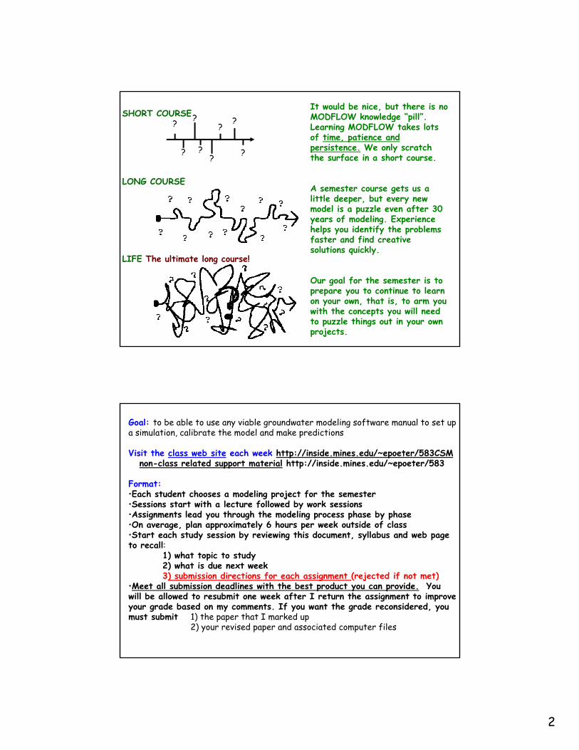
SHORT COURSE? ?
??
????
It would be nice, but there is no MODFLOW knowledge “pill”. Learning MODFLOW takes lots of time, patience and persistence. We only scratch the surface in a short course.
LONG COURSE
LIFE The ultimate long course!
A semester course gets us a little deeper, but every new model is a puzzle even after 30 years of modeling. Experience helps you identify the problems faster and find creative solutions quickly.
LIFE The ultimate long course!
Our goal for the semester is to prepare you to continue to learn on your own, that is, to arm you with the concepts you will need to puzzle things out in your own projects.
Goal: to be able to use any viable groundwater modeling software manual to set up a simulation, calibrate the model and make predictions
Visit the class web site each week http://inside.mines.edu/~epoeter/583CSMnon-class related support material http://inside.mines.edu/~epoeter/583
Format:•Each student chooses a modeling project for the semester•Sessions start with a lecture followed by work sessions•Assignments lead you through the modeling process phase by phase•On average, plan approximately 6 hours per week outside of class•Start each study session by reviewing this document, syllabus and web page to recall:
1) what topic to study2) what is due next week3) b i i di ti f h i t ( j t d if t t)3) submission directions for each assignment (rejected if not met)
•Meet all submission deadlines with the best product you can provide. You will be allowed to resubmit one week after I return the assignment to improve your grade based on my comments. If you want the grade reconsidered, you must submit 1) the paper that I marked up
2) your revised paper and associated computer files

3
Assignments:
Assignment #1 Conceptual ModelAssignment #2 Finite Difference Calculation & GridAssignment #3 Analytical ModelAssignment #4 Finite Difference SpreadsheetAssignment # 5 Steady State Numerical ModelsAssignment # 6 Model CalibrationAssignment # 7 Transient ModelingAssignment # 8 Analytical Transport ModelingAssignment # 9 Numerical Transport ModelingAssignment # 10 Final Presentation
Review the description in the syllabus as you start each. Use the outlines provided for guidance on your submission
WHY MODEL? SOLVE a PROBLEM or make a PREDICTION A Model is a A THINKING TOOL!
ALL IMPORTANT MECHANISMS & PROCESSES MUST BE INCLUDED IN THE MODEL, OR RESULTS WILL BE INVALID. KEEP AN OPEN MIND !
Make Predictions
Evaluate Uncertainty

4
hSWhKhKhK ∂=−⎟
⎞⎜⎛ ∂∂
+⎟⎟⎞
⎜⎜⎛ ∂∂
+⎟⎞
⎜⎛ ∂∂
Ground Water Models impose boundary conditions and solve the governing equation of Ground Water Flow:
tsSWzzK
zyyKyxxK
x ∂⎟⎠
⎜⎝ ∂∂
+⎟⎟⎠
⎜⎜⎝ ∂∂
+⎟⎠
⎜⎝ ∂∂
Geometry
Material Properties (K, S, T, Φe, D, R, etc)
Boundary Conditions (Head, Flux, Concentration etc)
Stresses (changing boundary conditions)
Qpumping well
1D flow to a well with Theis Boundary Conditions
EXAMPLE CONCEPTUAL MODEL:
wn
t th b ti ll
∞ ∞ Infinite Aquifer
No Flow Top and Bottom
log
s dr
awdo
w
log time
at the observation well …..p
5
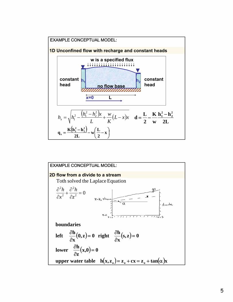
1D Unconfined flow with recharge and constant heads
w is a specified flux
EXAMPLE CONCEPTUAL MODEL:
h1 h2
Lx=0
constanthead
constanthead no flow base
( )⎟⎠⎞
⎜⎝⎛ −−
−= x
2Lw
L2hhKq
22
21
x
( ) ( )xxLKw
Lxhhhhx −+
−−=
22
212
1 L2hh
wK
2Ld
22
21 −−=
2D flow from a divide to a stream
0
Equation Laplace thesolvedToth
2
2
2
2
=∂∂
+∂∂
zh
xh
EXAMPLE CONCEPTUAL MODEL:
∂∂ zx
hhboundaries
∂∂
α
( ) ( )
( )
( ) ( )xtanzcxzz,xh tablewater upper
00,xzh lower
0z,sxhright 0z,0
xh left
ooo α+=+=
=∂∂
=∂∂
=∂∂

6
Toth’s result:
Prec
ipita
tion
ltrat
ion
EXAMPLE CONCEPTUAL MODEL (Turkey Creek Basin):
Evap
otra
n-sp
iratio
n
P
rnmpi
ngIn
fil
ISD
S R
etur
Pum

7
CRITICAL STEPS IN MODELING PROCESS * DEFINE THE PROBLEM * CONCEPTUAL MODEL DEVELOPMENT * DEFINING MATERIAL PROPERTIES * DEFINING BOUNDARY CONDITIONS * DEFINING INITIAL CONDITIONS, IF TRANSIENT * SELECTING APPROPRIATE EQUATION / CODE SELECTING APPROPRIATE EQUATION / CODE * CALIBRATION * CHECKING IF RESULTS MAKE SENSE * INTERPRETING RESULTS * DEALING WITH UNCERTAINTY
AFTER EACH STAGE OF MODELING ASK
DOES MY RESULT MAKE SENSE? DOES MY RESULT MAKE SENSE? HAS MY QUESTION BEEN ANSWERED SATISFACTORILY?
IF YES, STOP! WHAT WILL MORE MODELING GAIN? IF NO, USE RESULTS TO GUIDE FURTHER DATA COLLECTION
EXAMPLE OF A SIMPLE NUMERICAL MODEL- Complex geologic material distributions are simplified to discrete blocks- Numerical values define each block to represent geometry, properties, boundary
conditions, initial conditions and stresses to represent a groundwater system- Properties may vary between and within layers - BLOCKS may be INACTIVE (e.g. open circles) NO FLOW BOUNDARIES- BLOCKS may have SPECIFIED HEAD or SPECIFIED FLOW

8
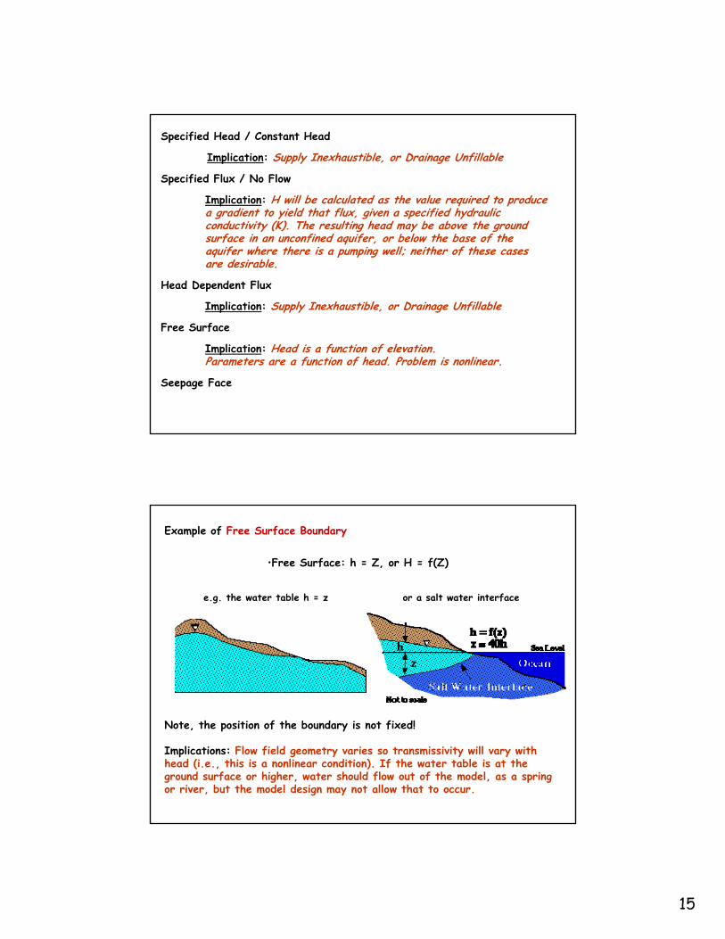
BOUNDARY CONDITIONSBoundary Types
Specified Head: head is defined as a function of space and time (ABC, EFG ) Constant Head: a special case of specified head (ABC, EFG)
Specified Flux: could be recharge across (CD) or zero across (HI)No Flow (Streamline): a special case of specified flux where the flux is zero (HI)
Head Dependent Flux: could replace (ABC, EFG)
Free Surface: water-table, phreatic surface (CD)
Seepage Face: h = z; pressure = atmospheric at the ground surface (DE)
Implication: Supply Inexhaustible, or Drainage Unfillable
Specified Head / Constant Head
Specified Flux / No Flow
Free Surface
Head Dependent Flux
Free Surface
Seepage Face

9
If heads are fixed at the ground surface to represent a swampy area, and an open pit mine is simulated by defining heads in the pit area, to the elevation of the pit bottom, the use of constant heads to represent the swamp will substantially overestimate in-flow to the pit. This is because the heads are inappropriately held high, while in the physical setting the swamp would dry up and
Example of Potential ProblemsFrom Misunderstanding/Misusing a Constant Head Boundary
physical setting, the swamp would dry up and heads would decline, therefore actual in-flow would be lower. The swampy area is caused by a high water table. It is not an infinite source of water.
Lesson: Monitor the in-flow at constant head boundaries and make calculations to assure yourself the flow rates are reasonable.
Model Field
When a well is placed near a stream, and the stream is defined as a specified head, the drawdown may be underestimated, if the pumping is large enough to affect the stream stage. The specified flux boundary may supply more water than the stream carries, and drawdowns should be greater, for the i i t Th t t
Example of Potential ProblemsFrom Misunderstanding/Misusing a Specified Head Boundary
given pumping rate. The stream stage, and flow rate, should decrease to reflect the impact of the pumping.
Lesson: Monitor the in-flow at specified head boundaries. Confirm that the flow is low enough relative to the stream flow, such that stream storage will not be affected.
Model Field

10
Implication: Supply Inexhaustible, or Drainage Unfillable
Specified Head / Constant Head
Implication: H will be calculated as the value required to produce a gradient to yield that flux, given a specified hydraulic
d ( ) h l h d b b h d
Specified Flux / No Flow
conductivity (K). The resulting head may be above the ground surface in an unconfined aquifer, or below the base of the aquifer where there is a pumping well; neither of these cases are desirable.
Free Surface
Head Dependent Flux
Free Surface
Seepage Face
In a simple unconfined aquifer with one well. If the injection flux is too large, calculated heads may be above the ground surface in unconfined aquifer models. If the withdrawal flux is too large, calculated heads may fall below the bottom of the aquifer, yet the
d l till i ld t
Example of Potential ProblemsFrom Misunderstanding/Misusing a Specified Flux Boundary
model may still yield water.
Lesson: Monitor calculated heads at specified flux boundaries to ensure that the heads are physically reasonable.
Injection Withdrawal

11
When a no flow boundary is used to represent a ground water divide, drawdown may be overestimated, and although the model does not indicate it, there may be impacts beyond the model boundaries. When a ground water divide is defined as a no-flow boundary, the flow system on the other side of the boundary cannot supply water to the well, therefore predicted drawdowns will be greater than would be
Example of Potential ProblemsFrom Misunderstanding/Misusing a No Flow Boundary
drawdowns will be greater than would be experienced in the physical system. The no-flow boundary prevents the ground water divide from shifting, implying the drawdown is zero on the other side of the divide.
Lesson: Monitor head at no flow boundaries used to represent flow lines or flow divides to ensure the location is valid even after the stress is applied.
Model Field
Implication: Supply Inexhaustible, or Drainage Unfillable
Specified Head / Constant Head
Implication: H will be calculated as the value required to produce a gradient to yield that flux, given a specified hydraulic
d ( ) h l h d b b h d
Specified Flux / No Flow
conductivity (K). The resulting head may be above the ground surface in an unconfined aquifer, or below the base of the aquifer where there is a pumping well; neither of these cases are desirable.
Free Surface
Head Dependent Flux
Implication: Supply Inexhaustible, or Drainage Unfillable
Free Surface
Seepage Face

12
Example of Potential ProblemsFrom Misunderstanding/Misusing a Head Dependent Flux Boundary
aquifer intoFlux =
Implications:
H1 = Specified head in reservoir H2 = Head calculated in model
AK'b'
HHq 21 −=
Implications: •If H2 is below AB, q is a constant and AB is the seepage face, but model may
continue to calculate increased flow. •If H2 rises, H1 doesn't change in the model, but it may in the field. •If H2 is less than H1, and H1 rises in the physical setting, then inflow is
underestimated. •If H2 is greater than H1, and H1 rises in the physical setting, then outflow is
overestimated.
Head-dependent Flux: General Head Boundary Q + or -
Conductance (is all of Darcy's Law except the head difference)
Q = KA dh/dl
Conductance = KA/thicknessQ = Conductance dh
Conductance of the ghb is calculated as:K * Area / thickness

13
Head-dependent Flux RIVER
Using River Stage and River Bed Conductance
Q KA dh/dlQ = KA dh/dl
Conductance = KA/thickness
Q = Conductance dh
Conductance of the river bed is calculated as:Kv * Area(the plan view area,L*W) / thickness
Head-dependent Flux RIVER
Q = Conductance dhi.e. CRIV dh
dh is limited to dh is limited to stage – bottom of sediment when bottom is above the water table

14
Head-dependent Flux DRAIN (outflow only)Q = KA dh/dlQ = Conductance dhConductance of the drain is calculated as:Kof material over which gradient is calculated *
Area/thicknessArea may be the cylindrical area midway between where the heads used for the gradient are located* length of the drain
Head-dependent Flux: ET only outflow
Q = Maximum when head is at or above the ET surface (usually ground surface) and li l d li t linearly declines to zero when head reaches extinction depth
15
Implication: Supply Inexhaustible, or Drainage Unfillable
Specified Head / Constant Head
Implication: H will be calculated as the value required to produce a gradient to yield that flux, given a specified hydraulic
d ( ) h l h d b b h d
Specified Flux / No Flow
conductivity (K). The resulting head may be above the ground surface in an unconfined aquifer, or below the base of the aquifer where there is a pumping well; neither of these cases are desirable.
Free Surface
Head Dependent Flux
Implication: Supply Inexhaustible, or Drainage Unfillable
Free Surface
Seepage Face
Implication: Head is a function of elevation. Parameters are a function of head. Problem is nonlinear.
•Free Surface: h = Z, or H = f(Z)
Example of Free Surface Boundary
e.g. the water table h = z or a salt water interface
Note, the position of the boundary is not fixed!
Implications: Flow field geometry varies so transmissivity will vary with head (i.e., this is a nonlinear condition). If the water table is at the ground surface or higher, water should flow out of the model, as a spring or river, but the model design may not allow that to occur.

16
Implication: Supply Inexhaustible, or Drainage Unfillable
Specified Head / Constant Head
Implication: H will be calculated as the value required to produce a gradient to yield that flux, given a specified hydraulic
d ( ) h l h d b b h d
Specified Flux / No Flow
conductivity (K). The resulting head may be above the ground surface in an unconfined aquifer, or below the base of the aquifer where there is a pumping well; neither of these cases are desirable.
Free Surface
Head Dependent Flux
Implication: Supply Inexhaustible, or Drainage Unfillable
Free Surface
Seepage Face
Implication: Head is a function of elevation. Parameters are a function of head. Problem is nonlinear.
Implication: Outflow occurs as needed given the problem parameters.
The saturated zone intersects the ground surface at atmospheric pressure and water discharges as evaporation or as a overland flow.
Example of Seepage Face Boundary
Note, the location of the surface is fixed but its length is not and is not know before solution of the problem.
Implications: A seepage surface is neither a head or flow line. Often seepage faces can be neglected in large scale models.

17
Common Designations for Several Important Boundary Conditions
After: Definition of Boundary and Initial Conditions in the Analysis of
Saturated Ground-Water Flow Systems – An Introduction, O. Lehn Franke, Thomas E. Reilly, and Gordon D. Bennett, USGS - TWRI Chapter B5, Book 3, 1987.
BOUNDARY CONDITION
NAME
BOUNDARY TYPE &
GENERAL NAME
FORMAL NAME
Constant Head &
Specified Head
Type 1
specified head
Dirichlet
No-Flow &
Type 2 Neumann&
Specified Flux specified flux Head-dependent
FluxType 3
mixed condition
Cauchy
Natural and Artificial Boundaries It is most desirable to terminate your model at natural geohydrologic boundaries.
However, we often need to limit the extent of the model in order to maintain the desired level of detail and still have the model execute in a reasonable amount of
time. Consequently models sometimes have artificial boundaries. For example, heads may be fixed at known water table elevations at a county line, or a flow line or
ground-water divide may be set as a no-flow boundary.
BOUNDARY TYPE NATURAL EXAMPLES ARTIFICIAL USES CONSTANT or SPECIFIED HEAD
Fully Penetrating Surface Water Features
Distant Boundary (Line of unchanging hydraulic head contour)
SPECIFIED FLUX Precipitation/Recharge Pumping/Injection Wells
Flow line Divide
Impermeable material Subsurface Influx HEAD DEPENDENT FLUX Rivers
Springs (drains) Evapotranspiration Leakage From a Reservoir or Adjacent Aquifer
Distant Boundary (Line of unchanging hydraulic head contour)
18
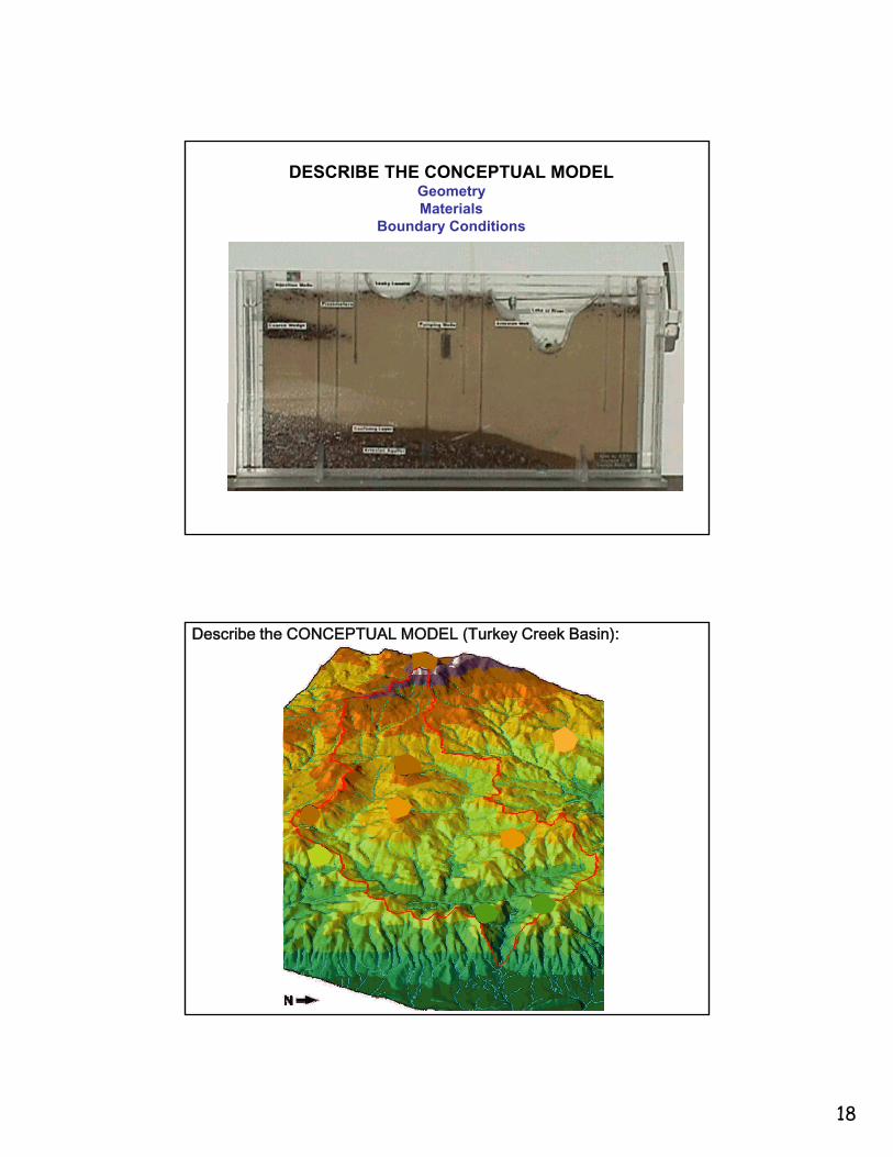
DESCRIBE THE CONCEPTUAL MODELGeometryMaterials
Boundary Conditions
Describe the CONCEPTUAL MODEL (Turkey Creek Basin):
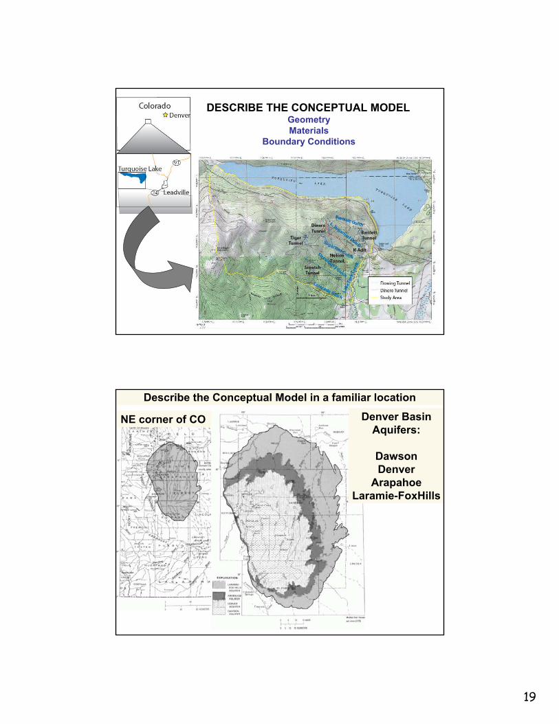
19
DESCRIBE THE CONCEPTUAL MODELGeometryMaterials
Boundary Conditions
Describe the Conceptual Model in a familiar location
NE corner of CO Denver BasinAquifers:
DawsonDenverDenver
ArapahoeLaramie-FoxHills

20
Denver BasinSouth - North
West - East
further south further north
Denver Basin
Precipitation (in/yr) Streams

21
Describe the Conceptual Model
Transmissivity ft2day-1
Bunker Hill BasinSouthern California
Danskin 2005
15”
20”25”25” Precip
Ground Water System Bunker Hill Basin
Dutcher & Garrett 1963
Danskin 2005
Danskin 2005

22
Ground Water System Bunker Hill Basin
1940’s confined water levels
current water levels water tableconfined
Danskin 2005Dutcher & Garrett 1963
Well HydrographsDanskin 2005Think Transients as well
Water levels were high in early years and good for recreationIncreased pumping led to problems with land subsidence
Urbanization resulted in less pumping & flooded foundationsThus pumping was increased to lower water levels
An additional 15,000AFY is needed to keep levels in checkProjections is growth will require an additional 50,000AFY
23
DUE NEXT WEEEK Assignment #1 Conceptual Model:Select a SINGLE-PHASE, CONSTANT DENSITY, SATURATED, FLOW modeling project with both a steady and transient aspect, and write a summary describing it to me. If you do not have a place to model, I can help you identify one. Your description should use illustrations and include:Title Objective Problem Description Geohydrologic Setting
FIGURES (at least one plan and one cross section) ARE REQUIRED TO ILLUSTRATE THE FOLLOWING ITEMS
l ( h )location (show on map)geometry (draw outline of modeled area on the maps and cross sections)boundary conditions (head and flux boundaries and head dependent flux boundaries)property value ranges (i.e. hydraulic conductivity, storage parameters, thicknesses)stresses that will be applied for which you will predict the resulting conditionsspecial considerations (if any)AT LEAST ONE FIGURE needs to show the outline of the area you will model with arrows indicating where water enters and leaves the system and a rough sketch of the pattern of flow through the area, hatched lines where there are no-flow boundaries and a few sketched lines indicating the pattern of flow in the area.Calibration Data that are available (head and groundwater discharge to surface water features). ( g g f f )Indicate location of stream flow gages and wells along with the frequency and period of record of flows and water levels) A description of what you envision your final result will beReferencesSubmit a description and the drawings as hard copy OR as ASSGN1_LASTNAME.ZIPALL FILES IN ZIP FILE MUST EITHER INCLUDE YOUR LAST NAME OR BE IN A
FOLDER THAT INCLUDES YOUR LAST NAME2 WEEKS FROM NOW AN ANALYTICAL MODEL OF SOME ASPECT OF
THIS NEEDS TO BE SUBMITTED
2 WEEKS FROM NOW but be thinking of it as you create your conceptual model * note typo in your pdf … 2 weeks from now not 3
Assignment #3 Analytical Model: Choose an analytical model to represent some aspect of your modeling project and implement it with your model conditions. Describe the problem set-up and solution in a concise and clear manner. If you use a spreadsheet, mathcad, or other code for calculation, provide at least one hand
l l ti t fi th t s lts t Y s b issi sh ld s calculation to confirm that your results are correct. Your submission should use illustrations to describe the conceptual model and how it fits your problem. It should include the following items:
Title Objective Problem DescriptionAnalytical Model DescriptionSimplification of System in order to use the analytical model Simplification of System in order to use the analytical model Parameter values usedCalculationsResults References
submit the write-up as hard copy and if you have electronic files include it in your zip file labeled: ASSGN3_LASTNAME.ZIP