GEAR PUMP Serie F, FM, FT - Välkommen till Tapflo · Pompa ad Ingranaggi - Serie F, FM, FT Gear...
29
Serie F, FM, FT GEAR PUMP OPERATING AND MAINTENANCE MANUAL POMPE CUCCHI s.r.l. POMPE CUCCHI s.r.l. 20090 Opera (MI) - ITALY Via dei Pioppi, 39 Tel.(+39) 02 57606287 (R.A.) Fax (+39) 02 57602257 e-mail: [email protected]
Transcript of GEAR PUMP Serie F, FM, FT - Välkommen till Tapflo · Pompa ad Ingranaggi - Serie F, FM, FT Gear...
Serie F, FM, FT
GEAR PUMP
OPERATING AND MAINTENANCE MANUAL
POMPE CUCCHI s.r.l.
POMPE CUCCHI s.r.l. 20090 Opera (MI) - ITALY Via dei Pioppi, 39
Tel.(+39) 02 57606287 (R.A.) Fax (+39) 02 57602257 e-mail: [email protected]
Pompa ad Ingranaggi - Serie F, FM, FT Gear Pump - F, FM, FT Series
5
CONTENTS
1. GENERAL INFORMATION .........................................................................................................25
1.1 SUPPLY CONDITIONS...................................................................................................25 1.2 MANUFACTURER..........................................................................................................25 1.3 USER MANUAL CONTENT ............................................................................................25 1.4 NAME, TYPE ..................................................................................................................26 1.5 NOISE EMISSIONS........................................................................................................26 1.6 APPLICATION FIELDS AND LIMITS. ALLOWED AND NOT ALLOWED USES..............26
2. TRANSPORT, HANDLING, PACKAGING, STORAGE...............................................................27
3. DESCRIPTION OF THE PUMP AND THE PUMP UNIT.........................................................................27
3.1 GENERAL DESCRIPTION OF THE MACHINE...............................................................27 3.2 WARNINGS ....................................................................................................................27 3.3 PROTECTION DEVICE ..................................................................................................28 3.4 ADDITIONAL DESCRIPTION OF ACCESSORIES .........................................................28
3.4.1 Seal parts............................................................................................................28 3.4.2 Safety valve ........................................................................................................28
4. INSTALLATION, ASSEMBLY.....................................................................................................29
4.1 SPECIAL ASSEMBLY TOOLS........................................................................................29 4.2 INSTALLATION SITE INFORMATION ............................................................................29
4.2.1 Space requirements for operation and installation...............................................29 4.2.2 Inspection before starting installation ..................................................................29 4.2.3 Foundation details...............................................................................................29 4.2.4 Alignment requirements ......................................................................................29 4.2.5 Suction lift ...........................................................................................................29
4.3 INITIAL INSTALLATION..................................................................................................31 4.3.1 Complete Pump Unit ...........................................................................................31 4.3.2 Free shaft pump..................................................................................................31
4.4 DRIVE UNIT AND ACCESSORY ASSEMBLY ................................................................32 4.4.1 Motor ..................................................................................................................32 4.4.2 Installation of safety and control devices .............................................................32
4.5 ELECTRICAL CONNECTIONS, CONNECTION CABLES ..............................................32 4.6 PIPING............................................................................................................................32
4.6.1 General ...............................................................................................................32 4.6.2 Forces and moments which operate on suction and delivery flanges. .................32 4.6.3 Fastening screw torques .....................................................................................33
5. COMMISSIONING, OPERATION, SHUTDOWN .........................................................................33
5.1 DOCUMENTATION ........................................................................................................33 5.2 PUMP PREPARATION FOR STARTUP .........................................................................33
5.2.1 Filling / discharge ................................................................................................33
Pompa ad Ingranaggi - Serie F, FM, FT Gear Pump - F, FM, FT Series
6
5.2.2 Electrical connections .........................................................................................33 5.2.3 Verifying the direction of rotation .........................................................................33
5.3 SAFETY DEVICES .........................................................................................................33 5.3.1 Mechanical safety devices (guards for rotating parts)..........................................33 5.3.2 Acoustic insulation ..............................................................................................34 5.3.3 Splash-proof cover ..............................................................................................34 5.3.4 Regulation on the electric components................................................................34
5.4 COMMISSIONING ..........................................................................................................34 5.4.1 Initial commissioning ...........................................................................................34 5.4.2 Startup after shutdowns ......................................................................................34 5.4.3 Pump system requirements.................................................................................35 5.4.4 Startup/shutdown frequency................................................................................35 5.4.5 Operation and startup with closed valve ..............................................................35
5.5 SHUTDOWN...................................................................................................................35 5.5.1 Decommissioning................................................................................................35 5.5.2 Emptying.............................................................................................................35
6. MAINTENANCE AND INSPECTION...........................................................................................35
6.1 USE PRECAUTIONS......................................................................................................35 6.2 WEARABLE MATERIALS ...............................................................................................36 6.3 SURVEILLANCE DURING OPERATION ........................................................................36 6.4 PREVENTIVE MAINTENANCE.......................................................................................36 6.5 PUMP DISASSEMBLY AND REASSEMBLY ..................................................................36
6.5.1 Tools...................................................................................................................36 6.5.2 Disassembly/reassembly procedure....................................................................36
7. FAULTS: CAUSES AND SOLUTIONS .......................................................................................40
8. WARRANTY CONDITIONS ........................................................................................................42
9. ALLEGATI/ANNEXES ................................................................................................................43
Pompa ad Ingranaggi - Serie F, FM, FT Gear Pump - F, FM, FT Series
25
1. GENERAL INFORMATION
1.1 SUPPLY CONDITIONS According to agreements with the Customer, the pump can be supplied either as bare shaft or pump unit. By pump unit we mean the pump coupled with the motor, including reduction gears and/or speed variators, if any. The coupling can be direct (FM or FT series) or through bell housing (F series).
1.2 MANUFACTURER The pump Manufacturer is POMPE CUCCHI S.R.L.. You can apply for assistance by sending a request to the following address:
Via dei Pioppi 39 - 20090 OPERA (MI) ITALY Tel. +39.02.57.60.62.87 (Hunting Line) Fax +39.02.57.60.22.57 E-mail : [email protected]
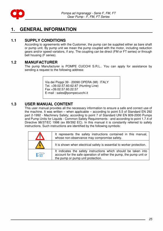
1.3 USER MANUAL CONTENT This user manual provides all the necessary information to ensure a safe and correct use of the machine. It was written – when applicable – according to point 5.5 of Standard EN 292 part 2-1992 - Machinery Safety; according to point 7 of Standard UNI EN 809-2000 Pumps and Pump Units for Liquids - Common Safety Requirements - and according to point 1.7.4 of Directive 98/37/EC 1998 (ex 89/392 EC). In this manual it is constantly referred to safety instructions. Such instructions are identified by the following symbols:
It represents the safety instructions contained in this manual, whose non-observance may compromise safety.
It is shown when electrical safety is essential to worker protection.
It indicates the safety instructions which should be taken into account for the safe operation of either the pump, the pump unit or the pump or pump unit protection.
Pompa ad Ingranaggi - Serie F, FM, FT Gear Pump - F, FM, FT Series
26
1.4 NAME, TYPE The pump standard execution is that with cast iron body, gears and shafts in hardened steel, with self-lubricating bushes made of sintered bronze and P.T.F.E. and ceramic/graphite/viton mechanic seal. The complete series covers different executions (body and gears in bronze or in AISI 316 stainless steel, with shafts in AISI 316)and different capacities. Moreover, executions with pre-heating chambers and special mechanic seal are also provided. The pump identification is realized through an alphanumeric code (see the following example): - 00FG015/WECDB00 : pump type F, cast iron execution, rated capacity 15 l/min. at 1500
rpm (displacement 14,6 cm3/rev), gears and shafts made of tempered steel, standard mechanic seal, equipped with brass safety valve, with bell housing for coupling with a Size 80 motor.
1.5 NOISE EMISSIONS - Reference standard: CEN/TC 197/SC3 N 21 E -fig.8- ISO 3744 on 6 positions - Measured values:
1 - Equivalent weighted continuous acoustic pressure level Leq = 80 dB(A); 2 - Maximum weighted instantaneous acoustic pressure C (peak level) Lpc < 82 dB(C).
- Test conditions: When measuring noise, the pumped liquid (ref. to oil with 30 cP viscosity) must be introduced into the testing system at a speed of less than 0.8 m/s into pipes. It must however reach laminar flow regime (thus the speed must be related to the viscosity) and the conditions outlined in this manual must be respected.
1.6 APPLICATION FIELDS AND LIMITS. ALLOWED AND NOT ALLOWED USES Each machine shall be used according to the type of application, operating conditions and liquid characteristics provided in contract specifications. Each variation which alters the intended use of the pump is forbidden and the User is fully responsible for it (e.g. the use of a liquid which is corrosive to pump materials rather than the recommended fluid, etc.). For variations in use within the application limits (e.g. fluid viscosity variations) it is advised to contact the Manufacturer in advance. In any case, the use of “KK” or alike plastic gears to allow the pump to operate also with poorly lubricating fluids, requires greater attention to avoid excessive or unexpected pressure loads. It is absolutely forbidden to use the machine in hazardous environments (explosive atmosphere, etc…), the use of hazardous substances (e.g. fluids with dangerous gases), in critical conditions (e.g. abnormal temperatures, etc…), which are not supplied with the pump. For pumps and pump units intended to be used in potentially explosive environments, please read carefully “Additional instructions for the operation and management of pumps and pump units intended to be used in potentially explosive atmospheres (Directive 94/9/EC)”.
Pompe Cucchi S.r.l. declines every responsibility for the consequences arising from an improper use of the machine which does not comply with what prescribed in this manual or specifically requested when ordering.
Pompa ad Ingranaggi - Serie F, FM, FT Gear Pump - F, FM, FT Series
27
2. TRANSPORT, HANDLING, PACKAGING, STORAGE
Pompe Cucchi sells “ex works”. Consequently, transport from the manufacturing shop to the named place of destination is carried out by the Customer under his own responsibility. For each transport a suitable standard packaging is ensured or established based on Customer requirements who, in any case, must give information about the type of shipment to be performed (by land, air, “overseas“). In case of long stationary periods under critical environmental conditions (such as: high humidity and/or salinity, etc.) the supply shall be stored in a protected environment.
3. DESCRIPTION OF THE PUMP AND THE PUMP UNIT
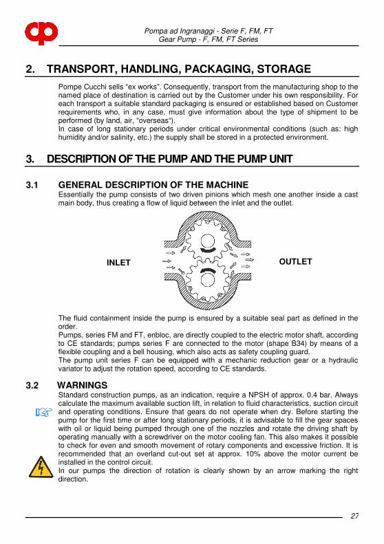
3.1 GENERAL DESCRIPTION OF THE MACHINE Essentially the pump consists of two driven pinions which mesh one another inside a cast main body, thus creating a flow of liquid between the inlet and the outlet.
The fluid containment inside the pump is ensured by a suitable seal part as defined in the order. Pumps, series FM and FT, enbloc, are directly coupled to the electric motor shaft, according to CE standards; pumps series F are connected to the motor (shape B34) by means of a flexible coupling and a bell housing, which also acts as safety coupling guard. The pump unit series F can be equipped with a mechanic reduction gear or a hydraulic variator to adjust the rotation speed, according to CE standards.
3.2 WARNINGS Standard construction pumps, as an indication, require a NPSH of approx. 0.4 bar. Always calculate the maximum available suction lift, in relation to fluid characteristics, suction circuit and operating conditions. Ensure that gears do not operate when dry. Before starting the pump for the first time or after long stationary periods, it is advisable to fill the gear spaces with oil or liquid being pumped through one of the nozzles and rotate the driving shaft by operating manually with a screwdriver on the motor cooling fan. This also makes it possible to check for even and smooth movement of rotary components and excessive friction. It is recommended that an overland cut-out set at approx. 10% above the motor current be installed in the control circuit. In our pumps the direction of rotation is clearly shown by an arrow marking the right direction.
INLET OUTLET
Pompa ad Ingranaggi - Serie F, FM, FT Gear Pump - F, FM, FT Series
28
The pump operating temperature in normal working conditions is about 80°C. In special pump versions, working temperatures of 180°C and more may be achieved. To protect personnel from dangers due to the temperatures reached during the operation of the machine, in the event of accidental contact (burn), the User must reduce the external pump temperature by means of insulation plates, coatings, screens, barriers, etc. As limit reference temperature for the contact surface it is advisable to take 55°C. Below this value, for hot smooth surfaces in bare metal, there is no burn threshold. For a detailed knowledge of this problem in relation to different particular cases, the User can read the standard UNI EN 563 Ed.’94, where burn thresholds are specified for several types of surface according to the “surface temperature - contact time” parameters. Liquids to be pumped must not contain abrasive or solid suspension as this will greatly reduce the pump life. At this purpose we recommend the installation of a properly sized filter on the suction line if solids may be present. When pumps are installed in parallel, the suction lines should be adequately separated to prevent unnecessary turbulence.
3.3 PROTECTION DEVICE The bell housing installed by the Manufacturer is made of an aluminium die-casting, fastened to the motor by screws, duly shaped to prevent fingers from coming into contact with moving parts. It can be removed only by using a proper tool.
3.4 ADDITIONAL DESCRIPTION OF ACCESSORIES
3.4.1 Seal parts The pump is usually supplied equipped with mechanical seal. If the Customer requires a particular type of seal, Pompe Cucchi S.r.l. installs the desired seal after verifying if its dimensions are compatible with those of the pump. In case the Customer requires only the seal mark, the Company leaves the Manufacturer to select the type of seal, by giving information about the pumped liquid.
3.4.2 Safety valve The pump can be equipped with a safety valve, with adjustable calibration, installed on the rear cover. After reaching the calibration pressure, prevailing on the contrast spring reaction, the valve starts opening by connecting the outlet side and the inlet side of the pump. The valve function is just to protect the pump from accidental pressure peaks. Its prolonged opening may imply the pump damaging.
Pompa ad Ingranaggi - Serie F, FM, FT Gear Pump - F, FM, FT Series
29
4. INSTALLATION, ASSEMBLY
4.1 SPECIAL ASSEMBLY TOOLS To assemble the pump you do not need special tools, except for seal extractors (see Maintenance).
4.2 INSTALLATION SITE INFORMATION
4.2.1 Space requirements for operation and installation The space destined by the Customer to the installation of the machine should be enough to gain access to, install and maintain the pump unit.
4.2.2 Inspection before starting installation Before installation, the Customer must ensure that the environmental conditions of the selected site comply with requirements specified under the contract. In particular, unless expressly required and accepted in the order, the installation site should not be exposed to the following environmental conditions: - abnormal temperature; - high humidity; - corrosive atmosphere; - explosion and/or fire hazard areas; - dust, sandstorms; - earthquakes and other similar external conditions; - high level of vibrations; - high altitude; - flood hazard areas.
4.2.3 Foundation details When the pump unit is installed, it shall be firmly fixed in place by fastening bolts or by using other securing methods. Ground fastening bolts or other securing methods shall be of sufficient strength to prevent the pump unit from moving accidentally.
4.2.4 Alignment requirements The alignment operation must not submit the pump unit to axial and radial stress, therefore the offset must always be lower than the tolerance limits expected for the coupling.
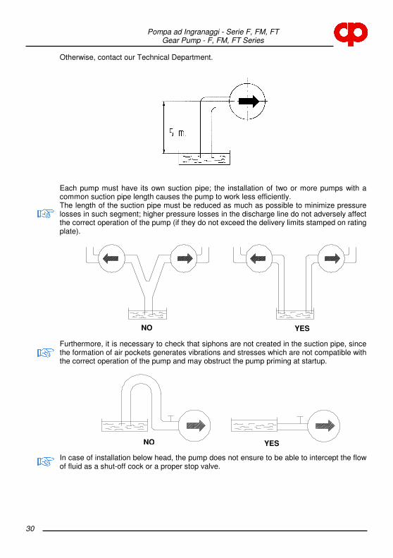
4.2.5 Suction lift The suction lift, that is the vertical distance between the pump inlet mid-point and the free surface of the tank to which the pump is attached, must not exceed 5 m to allow pump priming and avoid cavitation phenomena.
Pompa ad Ingranaggi - Serie F, FM, FT Gear Pump - F, FM, FT Series
30
Otherwise, contact our Technical Department.
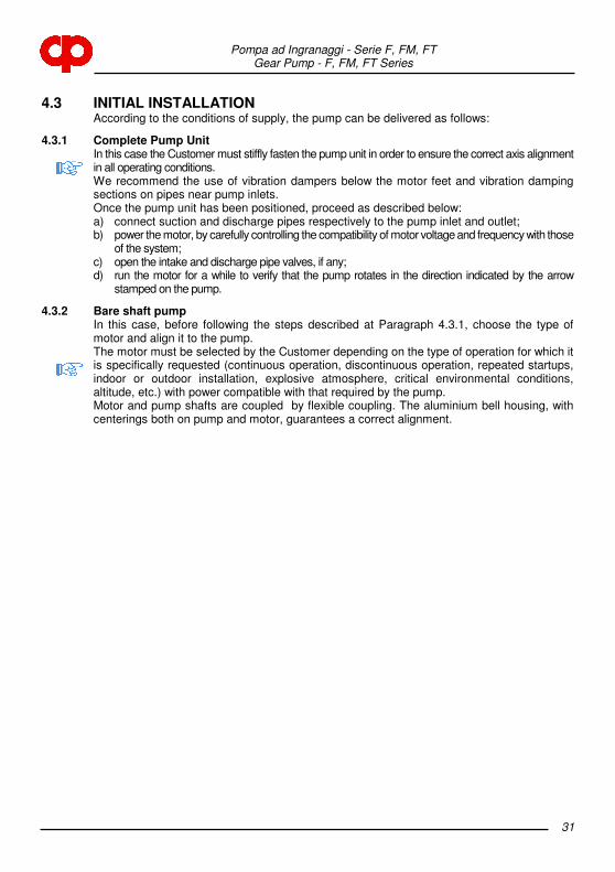
Each pump must have its own suction pipe; the installation of two or more pumps with a common suction pipe length causes the pump to work less efficiently. The length of the suction pipe must be reduced as much as possible to minimize pressure losses in such segment; higher pressure losses in the discharge line do not adversely affect the correct operation of the pump (if they do not exceed the delivery limits stamped on rating plate).
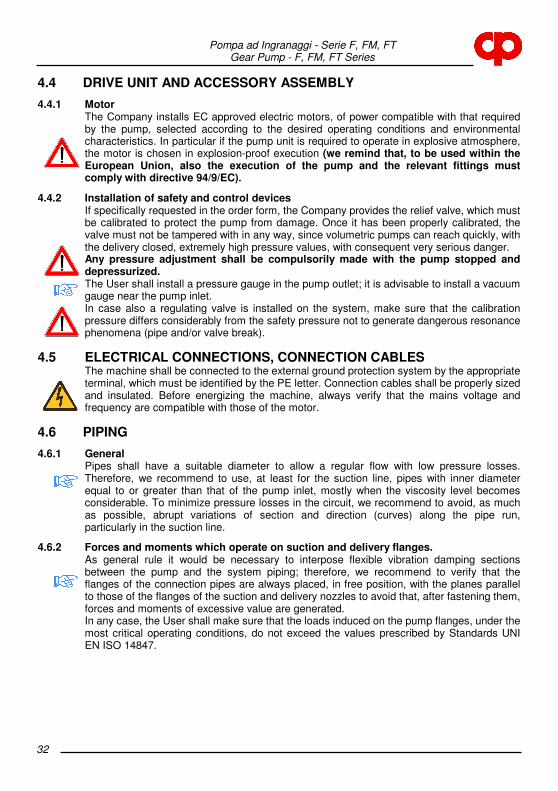
Furthermore, it is necessary to check that siphons are not created in the suction pipe, since the formation of air pockets generates vibrations and stresses which are not compatible with the correct operation of the pump and may obstruct the pump priming at startup.
In case of installation below head, the pump does not ensure to be able to intercept the flow of fluid as a shut-off cock or a proper stop valve.
NO YES
NO YES
Pompa ad Ingranaggi - Serie F, FM, FT Gear Pump - F, FM, FT Series
31
4.3 INITIAL INSTALLATION According to the conditions of supply, the pump can be delivered as follows:
4.3.1 Complete Pump Unit In this case the Customer must stiffly fasten the pump unit in order to ensure the correct axis alignment in all operating conditions. We recommend the use of vibration dampers below the motor feet and vibration damping sections on pipes near pump inlets. Once the pump unit has been positioned, proceed as described below: a) connect suction and discharge pipes respectively to the pump inlet and outlet; b) power the motor, by carefully controlling the compatibility of motor voltage and frequency with those
of the system; c) open the intake and discharge pipe valves, if any; d) run the motor for a while to verify that the pump rotates in the direction indicated by the arrow
stamped on the pump.
4.3.2 Bare shaft pump In this case, before following the steps described at Paragraph 4.3.1, choose the type of motor and align it to the pump. The motor must be selected by the Customer depending on the type of operation for which it is specifically requested (continuous operation, discontinuous operation, repeated startups, indoor or outdoor installation, explosive atmosphere, critical environmental conditions, altitude, etc.) with power compatible with that required by the pump. Motor and pump shafts are coupled by flexible coupling. The aluminium bell housing, with centerings both on pump and motor, guarantees a correct alignment.
Pompa ad Ingranaggi - Serie F, FM, FT Gear Pump - F, FM, FT Series
32
4.4 DRIVE UNIT AND ACCESSORY ASSEMBLY
4.4.1 Motor The Company installs EC approved electric motors, of power compatible with that required by the pump, selected according to the desired operating conditions and environmental characteristics. In particular if the pump unit is required to operate in explosive atmosphere, the motor is chosen in explosion-proof execution (we remind that, to be used within the European Union, also the execution of the pump and the relevant fittings must comply with directive 94/9/EC).
4.4.2 Installation of safety and control devices If specifically requested in the order form, the Company provides the relief valve, which must be calibrated to protect the pump from damage. Once it has been properly calibrated, the valve must not be tampered with in any way, since volumetric pumps can reach quickly, with the delivery closed, extremely high pressure values, with consequent very serious danger. Any pressure adjustment shall be compulsorily made with the pump stopped and depressurized. The User shall install a pressure gauge in the pump outlet; it is advisable to install a vacuum gauge near the pump inlet. In case also a regulating valve is installed on the system, make sure that the calibration pressure differs considerably from the safety pressure not to generate dangerous resonance phenomena (pipe and/or valve break).
4.5 ELECTRICAL CONNECTIONS, CONNECTION CABLES The machine shall be connected to the external ground protection system by the appropriate terminal, which must be identified by the PE letter. Connection cables shall be properly sized and insulated. Before energizing the machine, always verify that the mains voltage and frequency are compatible with those of the motor.
4.6 PIPING
4.6.1 General Pipes shall have a suitable diameter to allow a regular flow with low pressure losses. Therefore, we recommend to use, at least for the suction line, pipes with inner diameter equal to or greater than that of the pump inlet, mostly when the viscosity level becomes considerable. To minimize pressure losses in the circuit, we recommend to avoid, as much as possible, abrupt variations of section and direction (curves) along the pipe run, particularly in the suction line.
4.6.2 Forces and moments which operate on suction and delivery flanges. As general rule it would be necessary to interpose flexible vibration damping sections between the pump and the system piping; therefore, we recommend to verify that the flanges of the connection pipes are always placed, in free position, with the planes parallel to those of the flanges of the suction and delivery nozzles to avoid that, after fastening them, forces and moments of excessive value are generated. In any case, the User shall make sure that the loads induced on the pump flanges, under the most critical operating conditions, do not exceed the values prescribed by Standards UNI EN ISO 14847.
Pompa ad Ingranaggi - Serie F, FM, FT Gear Pump - F, FM, FT Series
33
4.6.3 Fastening screw torques The fastening torque for the screws of our pumps shall be: - for M6 screws 11-12 Nm - for M8 screws 20-22 Nm - for M10 screws 38-40 Nm For more detailed information, contact our Technical Department.
5. COMMISSIONING, OPERATION, SHUTDOWN
5.1 DOCUMENTATION Operating and maintenance manual
5.2 PUMP PREPARATION FOR STARTUP
5.2.1 Filling / discharge To prevent gears from running dry, before starting the pump for the first time or after long stationary periods it is advisable to fill the gear spaces with oil or liquid being pumped through one of the nozzles and rotate the driving shaft by operating manually with a screwdriver on the motor cooling fan. This also makes it possible to check for even and smooth movement of rotary components and excessive friction. The pump discharge, in case of toxic, noxious or, in any case, dangerous fluid, shall take place according to all the necessary cautions. In particular, the pump body shall be emptied according to proper operating maneuvers.
5.2.2 Electrical connections It is necessary to choose wires which satisfy the operating conditions required by the Customer (e.g. voltage, current, electric shock protection, bundle of cables) and can support external influences (e.g. ambient temperature, presence of water or corrosive substances, mechanical stresses, fire hazards). Moreover, we remind that wires must be properly sized to ensure the voltage drop from the power supply inlet to the point of load application does not exceed 4%.
5.2.3 Verifying the direction of rotation Open the intake and discharge valves. To verify the direction of rotation run the motor for a while only to check that the pump rotates in the direction marked by the arrows.
5.3 SAFETY DEVICES
5.3.1 Mechanical safety devices (guards for rotating parts) The hazardous area, represented by the projecting sections of pump side and motor side shafts and the coupling, shall be protected against accidental contact using bell housing, which must be firmly secured both to the motor and to the pump.
Pompa ad Ingranaggi - Serie F, FM, FT Gear Pump - F, FM, FT Series
34
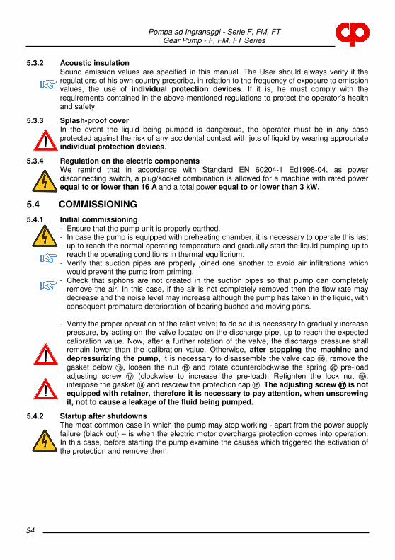
5.3.2 Acoustic insulation Sound emission values are specified in this manual. The User should always verify if the regulations of his own country prescribe, in relation to the frequency of exposure to emission values, the use of individual protection devices. If it is, he must comply with the requirements contained in the above-mentioned regulations to protect the operator’s health and safety.
5.3.3 Splash-proof cover In the event the liquid being pumped is dangerous, the operator must be in any case protected against the risk of any accidental contact with jets of liquid by wearing appropriate individual protection devices.
5.3.4 Regulation on the electric components We remind that in accordance with Standard EN 60204-1 Ed1998-04, as power disconnecting switch, a plug/socket combination is allowed for a machine with rated power equal to or lower than 16 A and a total power equal to or lower than 3 kW.
5.4 COMMISSIONING
5.4.1 Initial commissioning - Ensure that the pump unit is properly earthed. - In case the pump is equipped with preheating chamber, it is necessary to operate this last
up to reach the normal operating temperature and gradually start the liquid pumping up to reach the operating conditions in thermal equilibrium.
- Verify that suction pipes are properly joined one another to avoid air infiltrations which would prevent the pump from priming.
- Check that siphons are not created in the suction pipes so that pump can completely remove the air. In this case, if the air is not completely removed then the flow rate may decrease and the noise level may increase although the pump has taken in the liquid, with consequent premature deterioration of bearing bushes and moving parts.
- Verify the proper operation of the relief valve; to do so it is necessary to gradually increase
pressure, by acting on the valve located on the discharge pipe, up to reach the expected calibration value. Now, after a further rotation of the valve, the discharge pressure shall remain lower than the calibration value. Otherwise, after stopping the machine and depressurizing the pump, it is necessary to disassemble the valve cap @, remove the gasket below B, loosen the nut C and rotate counterclockwise the spring D pre-load adjusting screw A (clockwise to increase the pre-load). Retighten the lock nut C, interpose the gasket B and rescrew the protection cap @. The adjusting screw AAAA is not equipped with retainer, therefore it is necessary to pay attention, when unscrewing it, not to cause a leakage of the fluid being pumped.
5.4.2 Startup after shutdowns The most common case in which the pump may stop working - apart from the power supply failure (black out) – is when the electric motor overcharge protection comes into operation. In this case, before starting the pump examine the causes which triggered the activation of the protection and remove them.

Pompa ad Ingranaggi - Serie F, FM, FT Gear Pump - F, FM, FT Series
35
5.4.3 Pump system requirements In volumetric pumps, pressure is not related to flow rate and/or rotation speed; therefore, avoid installing shut-off valves on the discharge pipe and, in any case, between the pump and the stop valve a relief valve must always be installed.
5.4.4 Startup/shutdown frequency Pumps which are expressly requested by the Customer to start frequently and repeatedly do not show any problems for this kind of operation.
5.4.5 Operation and startup with closed valve It is forbidden to start the pump with the discharge valve closed: such mistake would cause an abrupt pressure rise above the limit values with consequent seizing.
5.5 SHUTDOWN
5.5.1 Decommissioning In case of decommissioning of the pump unit, it is necessary to disconnect the power supply to make unexpected and accidental startups impossible.
5.5.2 Emptying A pump or a pump unit which operates with a flammable, toxic, corrosive or, in any way, hazardous fluid, or with a liquid at a temperature higher than 55°C, shall be equipped with a device such as a connection pipe, to be provided by the User, to collect and dispose the liquid drained or coming from any possible leakage from the shaft seal or discharged by a pressure relief valve.
6. MAINTENANCE AND INSPECTION
6.1 USE PRECAUTIONS Before performing any maintenance operation, please observe the following safety precautions: - Never execute maintenance operations with the pump running. - Cut the power supply to the pump unit. - Wear gloves, glasses and protective suits adequate to the characteristics of the liquid
being pumped. - Wait until the pump is cooled. - Never open the pump unit and/or the relief valve when the pump is pressurized. - Close suction and discharge pipe valves, if any. - Disconnect the pump from suction and discharge pipes, by paying attention to put a
collecting basin for the pipe liquid. - Cut the power supply to the motor and disconnect the earth cable. - Unscrew anchoring screws and remove the pump unit. - Disconnect the pump from the motor, leaving the bell housing connected to the pump. - Place a collecting basin for the pump liquid. - Perform the maintenance operation. - Carry out the pump-motor coupling carefully. - Secure the unit by anchoring screws. - Connect the pump to suction and discharge pipes. - Reconnect the power supply to the motor and the earth cable.
- Open suction and discharge pipe valves, if any.
Pompa ad Ingranaggi - Serie F, FM, FT Gear Pump - F, FM, FT Series
36
- Reconnect the power supply to the pump unit.
6.2 WEARABLE MATERIALS The normal wear parts, included as spares in the 2-year warranty are the following: - bearing bushes; - seal parts (mechanical seal, gaskets); - gears; - shafts.
6.3 SURVEILLANCE DURING OPERATION The pump unit does not need the presence of an Operator during the work cycle. It is up to the User to provide or not a periodic surveillance depending on the importance and seriousness of the operation. The relevant checks shall be aimed to detect abnormal noise, vibration, temperature levels and/or some dripping from the mechanical seals, variations of pressure and/or flow rate, etc.
6.4 PREVENTIVE MAINTENANCE It is always advisable, for a reliable and cost-effective operation, to adopt a policy of preventive maintenance. The service time specified for wearable component parts in this manual can be used as reference for the first period of operation. Later the user will be able to improve the MTBM (Mean Time Between Maintenance) as a result of the acquired experience.
6.5 PUMP DISASSEMBLY AND REASSEMBLY
6.5.1 Tools No special tools are requested, except for seal extractors.
6.5.2 Disassembly/reassembly procedure Before disassembling the pump, it is necessary to perform the operations mentioned at point 6.1 "MAINTENANCE AND INSPECTION". Refer to the drawings and nomenclature attached at the end of the manual.
Pompa ad Ingranaggi - Serie F, FM, FT Gear Pump - F, FM, FT Series
37
a) Access to the mechanical seal In pumps series F, separate the spider bell housing from the motor and, after removing the key O from its seat unscrew screws ; fastening the spider Q to the pump body 1 and remove the seal cover K, without damaging the static part of the seal ?A, which is housed there. In this way, it is possible to check the wearing status of the seal contact surfaces. During re-assembly do not pinch the O-ring < housed in the seal cover. In pumps series FM – FT, carry out the same operations as item e) and then unscrew the screws ; fastening the pump body 1 to the motor and remove the conductor gear 4 and the tongue G. After accurately detecting the ring : position, remove it after unscrewing the dowel X. Remove gently the rotary part > of the mechanic seal and the seal cover = with the stationary ring >A and the O-ring <. It is possible to check the wearing status of the seal contact surface. During re-assembling, do not pinch the seal O-ring < housed in the seal cover. Grease the shaft and exert the helicoidal movement. Reposition the ring : correctly.
b) Replacing static seal In pumps series F, to remove the static part of the seal ? from the seal cover K, it is necessary to extract, by using special pliers, the seeger ring M housed in the cover, remove the ball bearing L and exert a pressure upon the external side of the seal. After placing the seal cover on a plane and greasing the walls to make assembly easier, insert the new static seal with the relevant O-ring; use a pad interposed with a soft bearing to exert the force perpendicularly to the cover. In pumps series FM – FT, remove the static part of the seal > from the seal cover = and replace it with a new one, without damaging the rubber sealing band.
c) Replacing dynamic seal In pumps series F, to remove the dynamic part of the seal ? it is advisable to use an iron wire bent at 90° at one end to hook the first or the second coil of the seal spring ? B. Exert a traction force parallel to the shaft N, by paying attention not to scratch this last. After greasing the shaft to make assembly easier, insert the new mechanical seal by rotating the spring in the direction opposite to that of the coil; use a pad interposed with soft bearing to press the seal up to make the spring ?B rest on the seeger W provided on the shaft. In pumps series FM – FT, carry out the same operations as item a).
d) Replacing bearing bushes Carry out the same operations as indicated in items a), b), c), e). To replace the supporting bushes H and J, bend them with a chisel or similar, paying attention not to damage the diameter of the bushing seats and remove them. Before inserting the new bushings, clean accurately the seat with alcohol to remove all impurities and wipe them very well. Insert the new bushings, which have to be slightly forced into their seats, to the stop beat. With regard to assembly, follow indications in items e), c), b), a).
e) Replacing gears and shafts Carry out the same operations as indicated in items a), b), c). After marking the related position between the rear cover 2 and the pump body 1, remove the socket head screws 7 fastening the cover and remove it, considering that the operation might be difficult because of the accuracy of shafts and dowel pins F. Remove the duct shaft 9, remove any stop springs V, remove the duct gear 8 from the shaft and remove the key 5; Carry out the same operation on the conductor shaft. During re-assembling, do not modify the position of the helicoidal tooth gears, in order not to reverse the axial thrust direction. During re-assembly, carry out operations according to the opposite order and do not rotate the rear cover 2 and do not pinch the O-ring 6 housed into it. Tighten the cover "cross"
Pompa ad Ingranaggi - Serie F, FM, FT Gear Pump - F, FM, FT Series
38
fastening screws 7 by rotating simultaneously the motor shaft, to avoid differentiated pressures on gears, which might increase frictions. With regard to tightening torques, see paragraph 4.6.3. Then carry out operations indicated in items c), a).
f) Safety valve replacement Unscrew the cap @ and remove the external sealing washer B. Move the nut C and unscrew completely the adjusting ring nut A, paying attention to the thrust exerted by the spring D; disassemble the internal sealing washer B. Remove the spring D with the shutter assembled E. During re-assembly check the correct coupling between the shutter E and the seat obtained in the rear cover 2 of the pump and replace both sealing washers B.
Pompa ad Ingranaggi - Serie F, FM, FT Gear Pump - F, FM, FT Series
39
BLANK PAGE
Pom
pa a
d In
gra
naggi - S
erie
F, F
M, F
T
Gear P
um
p - F
, FM
, FT
Serie
s
40
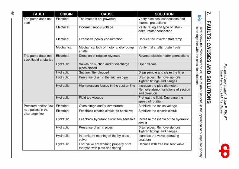
7.
FA
UL
TS
: CA
US
ES
AN
D S
OL
UT
ION
S
Here
belo
w th
e m
ost c
om
mon c
auses o
f malfu
nctio
ns in
the o
pera
tion o
f pum
ps a
re s
hortly
lis
ted to
geth
er w
ith th
e p
ossib
le s
olu
tions.
SOLUTION
Verify electrical connections and thermal protections
Verify rating and type of (star - delta) motor connection
Reduce the inverter start ramp
Verify that shafts rotate freely
Reverse electric motor connections
Open valves
Disassemble and clean the filter
Drain pipes. Remove siphons. Tighten fittings and flanges
Increase the pipe diameter. Remove abrupt variations of section and direction
Preheat the fluid. Decrease the speed of rotation.
Stabilize the mains voltage
Stabilize the electric circuit
Increase the inertia of the hydraulic circuit
Drain pipes. Remove siphons. Tighten fittings and flanges
Increase the valve operating pressure
Replace with free ball foot valve
CAUSE
The motor is not powered
Incorrect supply voltage
Excessive power consumption
Mechanical lock of motor and/or pump shafts
Direction of rotation reversed
Valves on suction and/or discharge pipes closed
Suction filter clogged
Presence of air in the suction pipe
High pressure losses in the suction line
Fluid too viscous
Overvoltage and/or overcurrent
Feedback electric circuit too sensitive
Feedback hydraulic circuit too sensitive
Presence of air in pipes
Intermittent opening of the by-pass valve
Foot valve not working properly or of the type with plate and spring
ORIGIN
Electrical
Electrical
Electrical
Mechanical
Electrical
Hydraulic
Hydraulic
Hydraulic
Hydraulic
Hydraulic
Electrical
Electrical
Hydraulic
Hydraulic
Hydraulic
Hydraulic
FAULT
The pump does not start
The pump does not suck liquid at startup
Pressure and/or flow rate pulses in the discharge line
Pom
pa a
d In
gra
naggi - S
erie
F, F
M, F
T
Gear P
um
p - F
, FM
, FT
Serie
s
41
SOLUTION
Drain pipes. Remove siphons. Tighten fittings and flanges
Decrease pressure losses in the suction line. Reduce the speed of rotation. Change fluid temperature
Replace ball bearing and/or bushes
Decrease pressure losses in pipes. Reduce fluid viscosity
Decrease the speed of rotation or increase the fluid temperature
Increase by-pass valve spring pre-load
Decrease pressure losses in the suction line. Change fluid temperature. Decrease speed of rotation.
Increase by-pass valve spring pre-load
Cool the fluid
Grind rear cover
Decrease the fluid temperature
CAUSE
Presence of air in pipes
Cavitation
Ball bearing and/or bush failure
Pump saturation
Excessive speed of rotation in relation to the fluid viscosity
By-pass valve opening
Cavitation
By-pass valve opening
Friction increase by thermal effect
Gear shim adjustment to a given clerance gear
Decrease in viscosity due to the temperature increase
ORIGIN
Hydraulic
Hydraulic
Mechanical
Hydraulic
Hydraulic
Hydraulic
Hydraulic
Hydraulic
Mechanical
Mechanical
Hydraulic
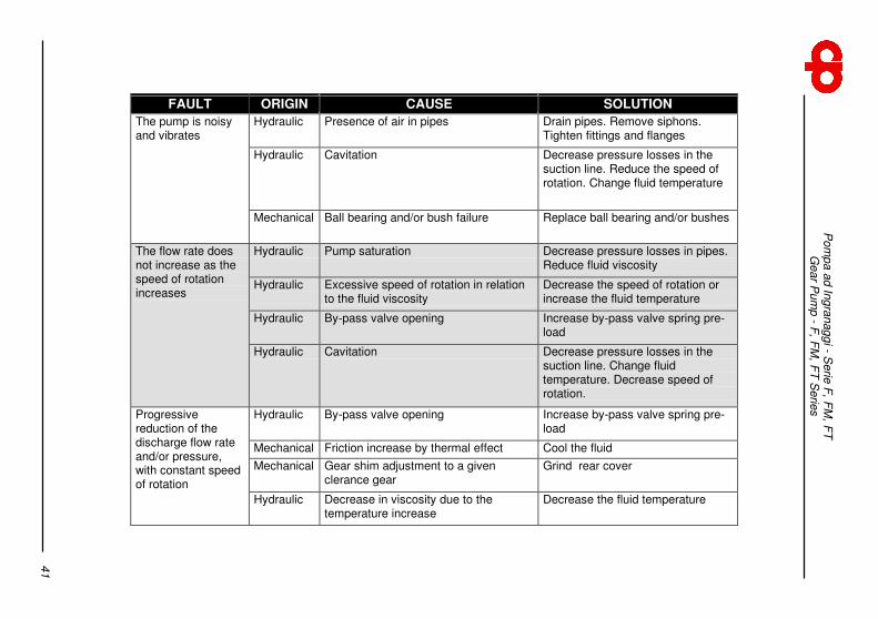
FAULT
The pump is noisy and vibrates
The flow rate does not increase as the speed of rotation increases
Progressive reduction of the discharge flow rate and/or pressure, with constant speed of rotation

Pompa ad Ingranaggi - Serie F, FM, FT Gear Pump - F, FM, FT Series
42
8. WARRANTY CONDITIONS
Pompe Cucchi S.r.l. guarantees that pumps and pump units are free from defects in material, construction, workmanship and assembly for a period of 12 (twelve) months from the delivery date (specified on the D.D.T.). The Purchaser's warranty is limited to the free replacement of parts, which are recognized faulty, by excluding the purchaser's right of requiring the contract cancellation or the price reduction or other damages. Warranty is void in case of misuse or improper use of the pump by the User. The pump shall be used according to what expressly requested in the order or based on the instructions contained in this manual. Any damages resulting from shocks and/or tampering are not covered by this warranty. Warranty does not apply to normal wear parts and damages due to negligence and poor maintenance. For the application of the warranty it is necessary that: - the Customers immediately notifies Pompe Cucchi s.r.l. the trouble he imputes to the
pump; - the pump was not tampered with; - the pump is returned to Pompe Cucchi s.r.l. clean, after removing any trace of the process
fluid and in a proper packaging; - a short description of the fault is provided in writing together with the operating parameters
of the pump or the pump unit; - if required, a chemical analysis or a sample of the process fluid is provided. Pumps which have not been emptied of the process fluid or installations outside the pump unit will not be taken into account. In the event Pompe Cucchi S.r.l. acknowledges the defect under warranty, no charge will be made to the Customer both for the replaced material and the workmanship. The forwarding charges from the Customer to Pompe Cucchi S.r.l. remain to the Sender’s (Customer) account.

Pompa ad Ingranaggi - Serie F, FM, FT Gear Pump - F, FM, FT Series
43
9. ALLEGATI/ANNEXES
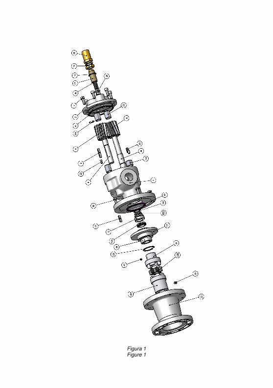
Figura 1 Figure 1
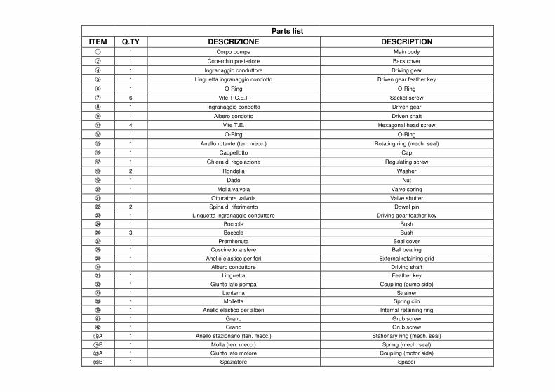
DESCRIPTION
Main body
Back cover
Driving gear
Driven gear feather key
O-Ring
Socket screw
Driven gear
Driven shaft
Hexagonal head screw
O-Ring
Rotating ring (mech. seal)
Cap
Regulating screw
Washer
Nut
Valve spring
Valve shutter
Dowel pin
Driving gear feather key
Bush
Bush
Seal cover
Ball bearing
External retaining grid
Driving shaft
Feather key
Coupling (pump side)
Strainer
Spring clip
Internal retaining ring
Grub screw
Grub screw
Stationary ring (mech. seal)
Spring (mech. seal)
Coupling (motor side)
Spacer
DESCRIZIONE
Corpo pompa
Coperchio posteriore
Ingranaggio conduttore
Linguetta ingranaggio condotto
O-Ring
Vite T.C.E.I.
Ingranaggio condotto
Albero condotto
Vite T.E.
O-Ring
Anello rotante (ten. mecc.)
Cappellotto
Ghiera di regolazione
Rondella
Dado
Molla valvola
Otturatore valvola
Spina di riferimento
Linguetta ingranaggio conduttore
Boccola
Boccola
Premitenuta
Cuscinetto a sfere
Anello elastico per fori
Albero conduttore
Linguetta
Giunto lato pompa
Lanterna
Molletta
Anello elastico per alberi
Grano
Grano
Anello stazionario (ten. mecc.)
Molla (ten. mecc.)
Giunto lato motore
Spaziatore
Q.TY
1
1
1
1
1
6
1
1
4
1
1
1
1
2
1
1
1
2
1
1
3
1
1
1
1
1
1
1
1
1
1
1
1
1
1
1
Parts list
ITEM 1
2
4
5
6
7
8
9
;
<
?
@
A
B
C
D
E
F
G
H
J
K
L
M
N
O
P
Q
V
W
Y
Z
?A
?B
PA
PB
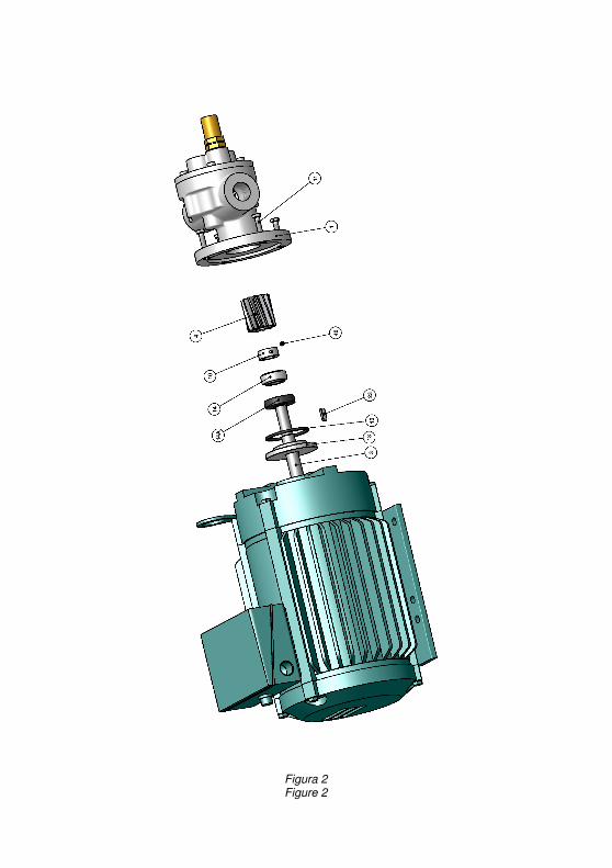
Figura 2 Figure 2
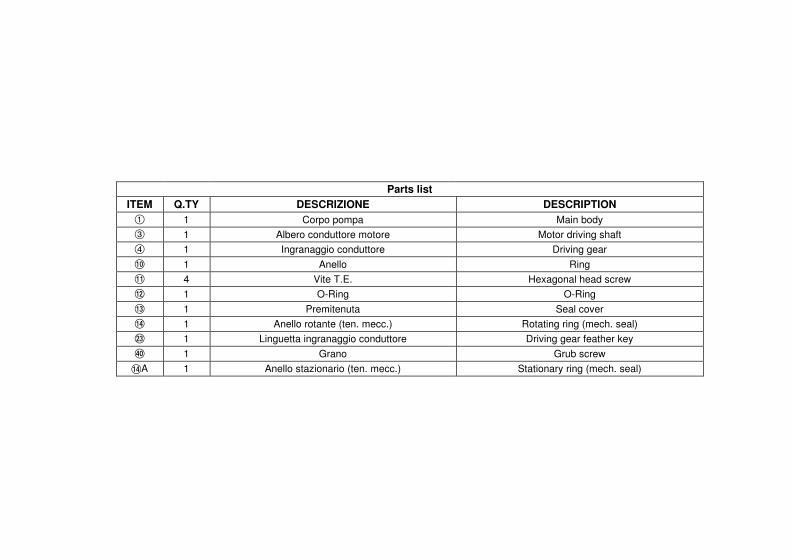
DESCRIPTION
Main body
Motor driving shaft
Driving gear
Ring
Hexagonal head screw
O-Ring
Seal cover
Rotating ring (mech. seal)
Driving gear feather key
Grub screw
Stationary ring (mech. seal)
DESCRIZIONE
Corpo pompa
Albero conduttore motore
Ingranaggio conduttore
Anello
Vite T.E.
O-Ring
Premitenuta
Anello rotante (ten. mecc.)
Linguetta ingranaggio conduttore
Grano
Anello stazionario (ten. mecc.)
Q.TY
1
1
1
1
4
1
1
1
1
1
1
Parts list
ITEM
1
3
4
:
;
<
=
>
G
X
>A
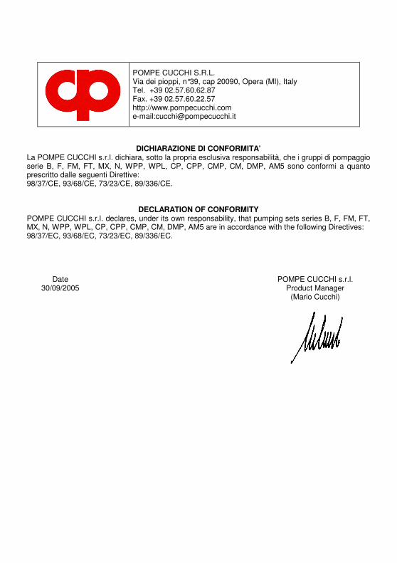
POMPE CUCCHI S.R.L. Via dei pioppi, n°39, cap 20090, Opera (MI), Italy Tel. +39 02.57.60.62.87 Fax. +39 02.57.60.22.57 http://www.pompecucchi.com e-mail:[email protected]
DICHIARAZIONE DI CONFORMITA’ La POMPE CUCCHI s.r.l. dichiara, sotto la propria esclusiva responsabilità, che i gruppi di pompaggio serie B, F, FM, FT, MX, N, WPP, WPL, CP, CPP, CMP, CM, DMP, AM5 sono conformi a quanto prescritto dalle seguenti Direttive: 98/37/CE, 93/68/CE, 73/23/CE, 89/336/CE.
DECLARATION OF CONFORMITY POMPE CUCCHI s.r.l. declares, under its own responsability, that pumping sets series B, F, FM, FT, MX, N, WPP, WPL, CP, CPP, CMP, CM, DMP, AM5 are in accordance with the following Directives: 98/37/EC, 93/68/EC, 73/23/EC, 89/336/EC. Date POMPE CUCCHI s.r.l. 30/09/2005 Product Manager (Mario Cucchi)
POMPE CUCCHI S.R.L. Via dei pioppi, n°39, cap 20090, Opera (MI), Italy Tel. +39 02.57.60.62.87 Fax. +39 02.57.60.22.57 http://www.pompecucchi.com e-mail:[email protected]
DICHIARAZIONE DI INCORPORAZIONE PER FORNITURA DI POMPE AD ASSE NUDO
La POMPE CUCCHI s.r.l. dichiara, sotto la propria esclusiva responsabilità, che le pompe serie B, F, FM, FT, MX, N, WPP, WPL, CP, CPP, CMP, CM, DMP, AM5 sono conformi per progetto a quanto prescritto dalla Direttiva 98/37/CE. Esse non possono essere messe in servizio prima che i gruppi di pompaggio siano stati correttamente assemblati e dichiarati conformi alle seguenti Direttive: 98/37/CE, 93/68/CE, 73/23/CE, 89/336/CE.
DECLARATION OF INCORPORATION FOR SUPPLY OF BARE SHAFT PUMPS
POMPE CUCCHI s.r.l. declares, under its own responsability, that pumps series B, F, FM, FT, MX, N, WPP, WPL, CP, CPP, CMP, CM, DMP, AM5 have been designed in accordance with the 98/37/EC Directive. They cannot be put into operation before the pumping sets have been correctly assembled and declared in accordance with the following Directives: 98/37/EC, 93/68/EC, 73/23/EC, 89/336/EC.
Date POMPE CUCCHI s.r.l. 30/09/2005 Product Manager (Mario Cucchi)

Edizione : 03/2006 Edition : 03/2006
POMPE CUCCHI s.r.l.