Gear Inspection and Measurement - Gear Technology · 44 GEAR TECHNOLOGY Gear Inspection and...
6
44 GEAR TECHNOLOGY Gear Inspection and Measurement Robert Moderow, ITW., Imnois Tools, Uncolnwood l , It The purpose of gear inspection is to: • Assure required accuracy and quality, • Lower overall cost of manufacture by con- trolling rejects and scrap. • Control machines and machining practices and maintain produced accuracy as machines and tools wear, • Determine heat treat distortions to. make necessary corrections .. Basic Gear Ins-pection Terms Runout (Radial) - The total variation ofthe radial distance of a geal"s teeth from its center (or bore). Runourerrors contribute to gear noise, binding. and additional stress in mating gears. Runout (Sectional) - A condition of radial runount where much of the error occurs in dew teeth and is not evenly distributed over the entire gear. This is a more severe error than evenly distributed nmout. Runout (Axial) - Also called wo bhie or face runout, The total variation ofa gear's teeth along its axis, measured from a reference plane per- pendicular to its axis. While in itself not detri- mental, it is almost always accompanied by lead variation, which causes excessive stress, noise. and possible binding in mating gears. Lead - The axial advance of a screw thread (or gear tooth) in one turn (revolution, 360°). Lead Error - The difference between the theoretical leadtrace and the actual lead trace. Usually measured from one end of the tooth to the other, normal to the theoretical lead trace. Contributes tuend-of-tooth contact with the mating gear, causing possible noise, surface crushing. binding, and early failure. Lead A verage- The ave[a~e of the lead error of the gears teeth. Usually based on four lead traces taken around the gear at 90 0 intervals . Lead Variation - The condition in a gear where some teeth vary in lead. plus and minus, from the average lead. Total Lead Variation - The total amount of lead variation, plus to minus. Usually based on four lead traces taken around the gear at 90,0 intervals .. Plus Lead, Minus Lead - Plus lead is minus helix angle. Minus lead is plus helix angle .. (See Fig. 3.) Involute (Profile) - The curved shape of the gear teeth, usually from the S.A.P. or T.I.F. to the end of the tooth. Involute (Pm/ile) Error - The difference between the theoretical profile and the measured profile .. Call cause noise, stresses, and early failure in mating gears. Involute (Profile) Average - The average of the profile error the gear's teeth, Usually of four profile traces taken around the gear at 90° intervals .. Involute (Profile) Variation - The total amount of profile variation, plus to minus. Usu- any of four profile traces taken around the gear at 90° intervals. Total Involute (Profile) Va riation - The total amount of profile variatien, plus to minus. Usu- ally of four profile traces taken around the gear at 90° intervals. Plus Involute, Minus Involute - Plus involute is plus material a1 tip of gear. Minus involute is minus material at tip of gear ..(See Fig. 4.) Spacing - The measured distance between corresponding points on adjacent gear teeth.
Transcript of Gear Inspection and Measurement - Gear Technology · 44 GEAR TECHNOLOGY Gear Inspection and...
44 GEAR TECHNOLOGY
Gear Inspectionand Measurement
Robert Moderow,ITW., Imnois Tools, Uncolnwoodl, It
The purpose of gear inspection is to:• Assure required accuracy and quality,• Lower overall cost of manufacture by con-
trolling rejects and scrap.• Control machines and machining practices
and maintain produced accuracy as machinesand tools wear,
• Determine heat treat distortions to. makenecessary corrections ..
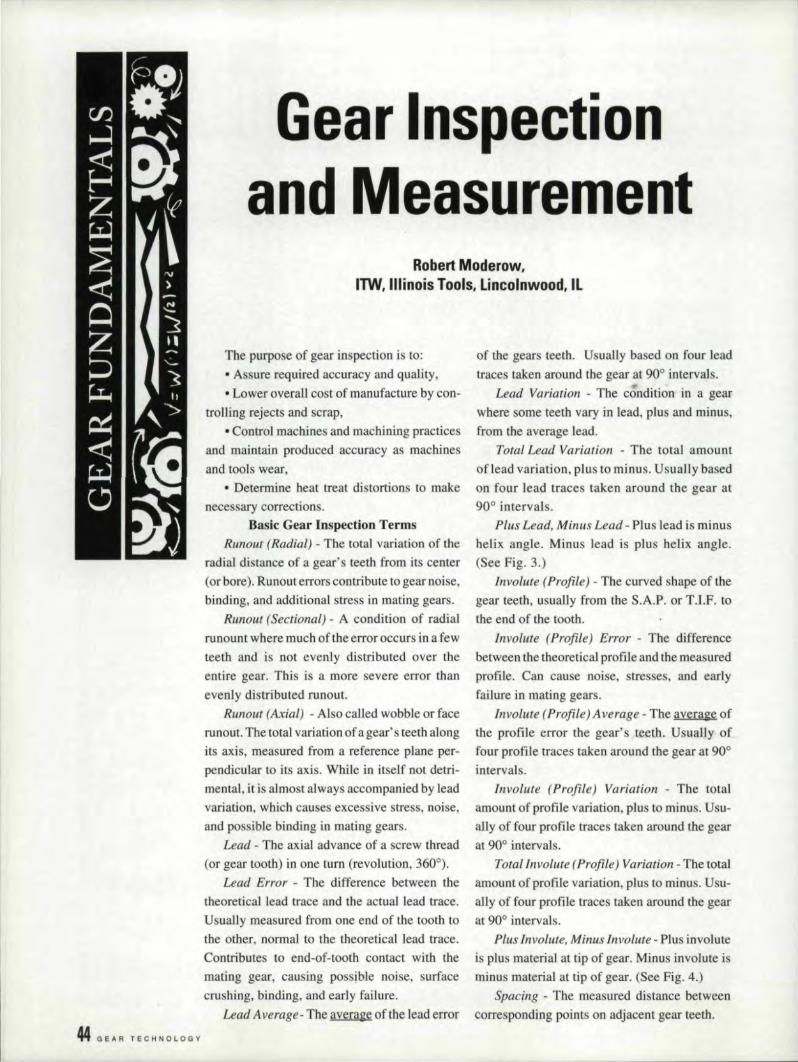
Basic Gear Ins-pection TermsRunout (Radial) - The total variation ofthe
radial distance of a geal"s teeth from its center(or bore). Runourerrors contribute to gear noise,binding. and additional stress in mating gears.
Runout (Sectional) - A condition of radialrunount where much of the error occurs in dewteeth and is not evenly distributed over theentire gear. This is a more severe error thanevenly distributed nmout.
Runout (Axial) - Also called wobhie or facerunout, The total variation ofa gear's teeth alongits axis, measured from a reference plane per-pendicular to its axis. While in itself not detri-mental, it is almost always accompanied by leadvariation, which causes excessive stress, noise.and possible binding in mating gears.
Lead - The axial advance of a screw thread(or gear tooth) in one turn (revolution, 360°).
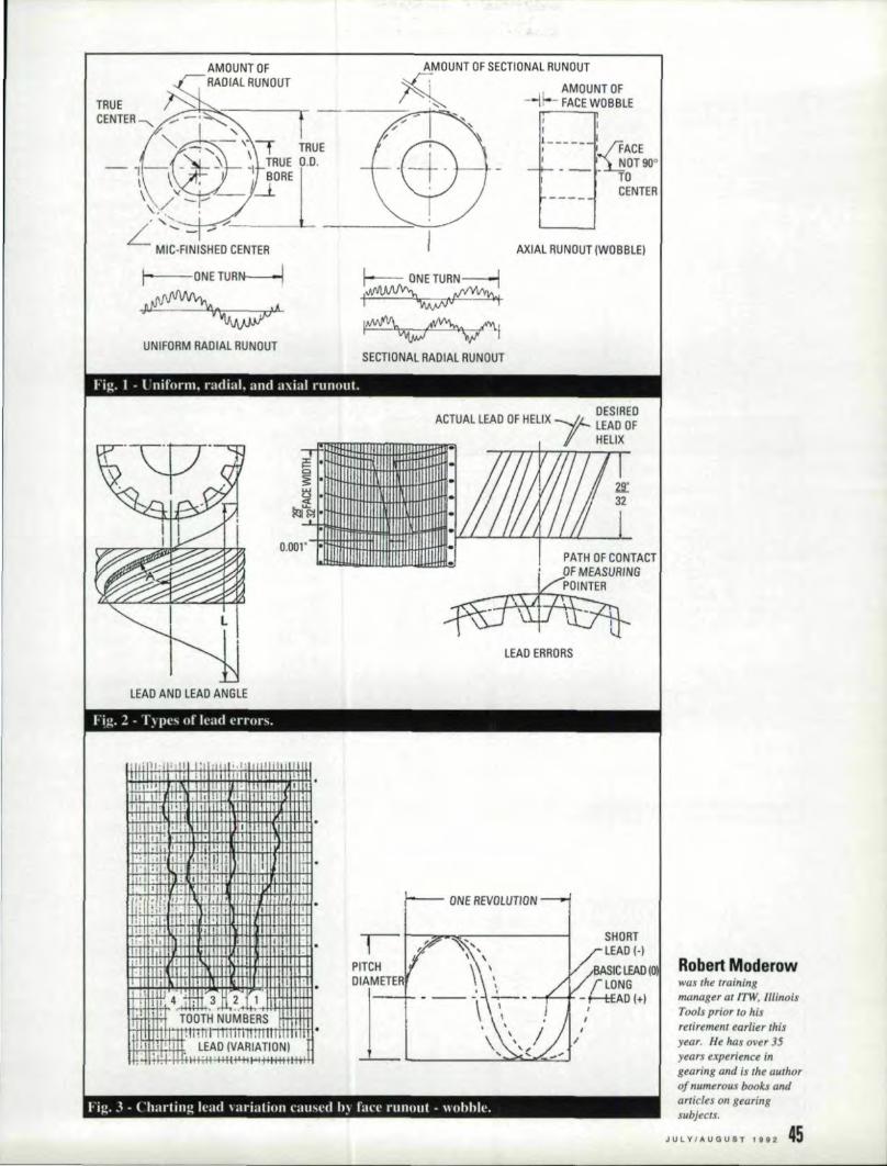
Lead Error - The difference between thetheoretical leadtrace and the actual lead trace.Usually measured from one end of the tooth tothe other, normal to the theoretical lead trace.Contributes tuend-of-tooth contact with themating gear, causing possible noise, surfacecrushing. binding, and early failure.
Lead A verage- The ave[a~e of the lead error
of the gears teeth. Usually based on four leadtraces taken around the gear at 900 intervals .
Lead Variation - The condition in a gearwhere some teeth vary in lead. plus and minus,from the average lead.
Total Lead Variation - The total amountof lead variation, plus to minus. Usually basedon four lead traces taken around the gear at90,0 intervals ..
Plus Lead, Minus Lead - Plus lead is minushelix angle. Minus lead is plus helix angle ..(See Fig. 3.)
Involute (Profile) - The curved shape of thegear teeth, usually from the S.A.P. or T.I.F. tothe end of the tooth.
Involute (Pm/ile) Error - The differencebetween the theoretical profile and the measuredprofile .. Call cause noise, stresses, and earlyfailure in mating gears.
Involute (Profile) Average - The average ofthe profile error the gear's teeth, Usually offour profile traces taken around the gear at 90°intervals ..
Involute (Profile) Variation - The totalamount of profile variation, plus to minus. Usu-any of four profile traces taken around the gearat 90° intervals.
Total Involute (Profile) Va riation - The totalamount of profile variatien, plus to minus. Usu-ally of four profile traces taken around the gearat 90° intervals.
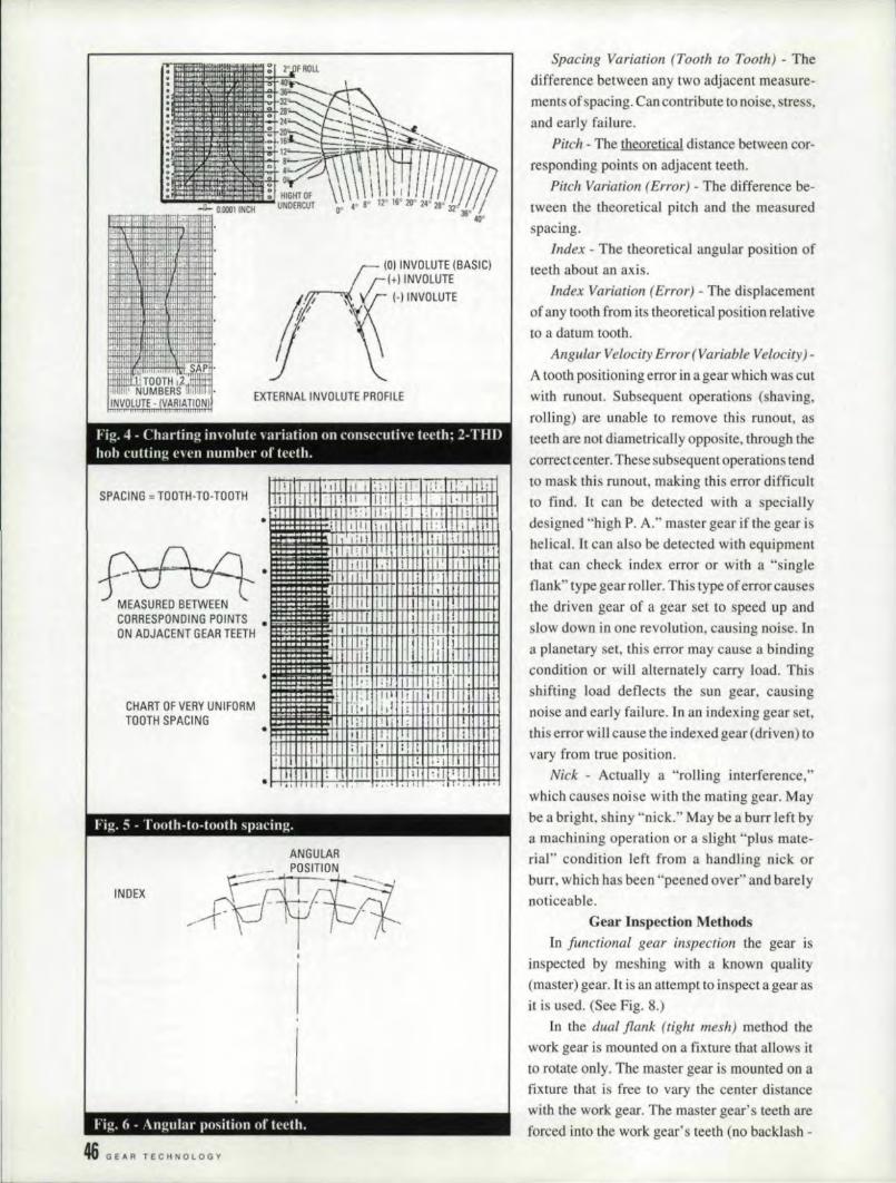
Plus Involute, Minus Involute - Plus involuteis plus material a1 tip of gear. Minus involute isminus material at tip of gear ..(See Fig. 4.)
Spacing - The measured distance betweencorresponding points on adjacent gear teeth.
rig. 1 - l'nifurm, radial. and axial runout.-- -------
lRUECENlER-....
UNIFORM RADilAl RUN,OUl
AXIAL IRUNOUT (WOBBLEI
~ ONE iURN-::--1
I~
~ISECTIONAL RADIAL RUN OUT
1'1 I I -.
1 ii,' i~ t·~ I
1 -r
, "
++f ! 4~: ..,3r ~..HtJ ,lffi ' lOOTH NUMBERS '. ;
M..,. ;:".:I ..I·'I.ll.TIlIl.II~lTITmlmlfT.. I :1". ,,' I. LEAD iVARIATIONI l'
. 1+8 ,H+i+H++I+'#I-'-It+Htt+I+i+."!
LEAD ERRORS
hg. 1 - "1') 1)('"IIf lead errurs.------ ------
.' i 1'11' ;" II I' 'I ",. I I ,IIII I ; II 11 ,
, .1~,+I'~'~'~'N~~~~~~rt'·~I~, ,,,,,,. '1'1
lEAID AND lIEAOANG'lE
, II
H. I ';
, I' I Fill I
SHOR,T~ LEAD (-j
Roben M!oderowwasthe trainingm,mager at 'TW, IllinoisTools prior to hisrelir:ement earlier thisyear. He has over 35years experience ingearing and is the authorof numerous books ,andarticles on gearingsubjects.
JULV/AUGUST 1&92145
I I
PITCHIDIAMETER'
['--..--1- ~--
hl-\. J - (.'harling lead \ arjatjnn cau..t'd h~ rm.'t' runnut - \\ ohbh:--- -
(0) INVOLUTE (BASIC)(+J INVOliUTE(-I INVOLUTE
EXTERNAL INVOLUTE PROFILE
Fig. 4 - Charting im elute \ ariatlon nn consecutive teeth: 2-THDhob flitting e\ en number of teeth.
SPACING = TOOTH-TO·TOOTHTIIIIT· 'dll" 1;,",,:11 Ilil,' 1:',lildT!!!I ,I, II: II II! "i II : 1:11 ;In
.. :111 II uu '~'i I" 11·1 :1·,llIlt 1H!!I'III i,l illl:IIU;J11rT, I: Ii II, . 11,1,1"1 ; j IIlIil,!IIT!, [!II'IIIIIIJ'\
:111 ,IIII,I,! ! III ill' I.1 I Ilillll I : rr"IL .j
,jlllllllll II",1 111'11 I '!l
..MEASURED BETWEENCORRESPONDING POINTS ..ON ADJACENT GEAR TEETH
CHART OF VERY UNIFORMTOOTH SPACING ..
,
I[II, II 11111.:1 \1,: ;'1 II i 1~r• I
- I. I
IITI: -!flll,,11I 1111 'd:'ll 11111,,11.·.,'il··
Fig. 5 - Tooth-to-tooth sparing.------- -------- -----
ANGULAR
POS~INDEX
Fig. 6 - Angular position of teeth.
46 GEA.R TECHNOLOGY
Spacing Variation (Tooth to Tooth) - Thedifference between any two adjacent measure-ments of spacing. Can contribute to noise, stress,and early failure.
Pitch - The theoretical distance between cor-responding points on adjacent teeth,
Pitch Variation (Error) - The difference be-
tween the theoretical pitch and the measuredspacing.
Index - The theoretical angular position ofteeth about an axis.
Index Variation (Error) - The displacementof any tooth from its theoretical. position relati vetoa datum tooth.
Angular Velocity Error (Variable Velocity)-A tooth positioning error in a gear which was cutwith runout. Subsequent operations (shaving,rolling) are unable to remove this runout, asteeth are not diametrically opposite, through thecorrect center ..These subsequent operations tendto mask this runout, making this error difficultto find. It can be detected with a speciallydesigned "high P. A." master gear if the gear ishelical. It can also be detected with equipmentthat can check index error or with a "singleflank" type gear roller. This type of'error causesthe driven gear of a gear set to speed up and
slow down in one revolution, causing noise. Ina planetary set, this error may cause a bindingcondition or win alternately carry load. Thisshifting load deflects the sun gear, causingnoise and early failure. In an indexing gear set,this error will cause tile indexed gear (driven) tovary from true position.
Nick - Actually a "rolling interference,"which causes noise with the mating gear. Maybe a bright, shiny "nick." May be a.burr left by11 machining operation Of a slight "plus mate-rial" condition left from a handling nick orburr, which has been' 'peened over" and barelynoticeable.
Gear Inspeetlen MethodsIn functional gear inspection. the gear is
inspected by meshing with a known quality(master) gear. It is an attempt toinspect a gear asit is used. (See Fig. 8.)
In the dual flank (tigh.t mesh) method thework gear is mounted on a fixture that allows itto rotate only. The master gear is mounted on afixture that is free to vary the center distancewith the work gear ..The master gear's teeth areforced into the work gear's teeth (no backlash -
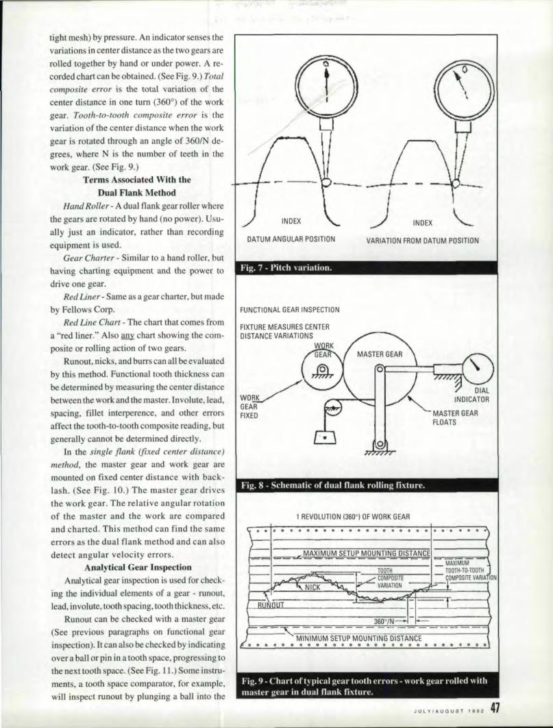
tight me h) by pressure. An indicator senses thevariations in center distance as the two gears arerolled together by hand or under power ..Are-corded chart can be obtained. (See Fig. 9.) Totalcomposi.re error is the total variation 'Of thecenter distance in one turn (360°) of the workgear. Tooth-fa-tooth composite enol' is thevariation of the center distance when the workgear is rotated through an angle of 3601N de-grees, where N is the number of teeth in thework gear. (See Fig ..9.)
Terms Associated With theDual Flank Method
Hand Roller- A dual flank gear roller wherethe gears are rotated by band (no power). Usu-ally just an indicator. rather than recordingequipment is used.
Gear Charter - Similar to a hand roller, buthaving charting equipment and the power todrive one gear.
Red Liner - Same as a gear charter, but madeby Fellow Corp.
Red Line Chart - The chart that comes froma "red liner," Also IDlYchart showingthe com-posite or rolling action of two gears.
Runout, nicks, and burrs can all be evaluatedby this method. Functional tooth thickness canbe determined by measuring the center distancebetween the work and the master. Involute, lead,spacing, fillet interperence, and other errorsaffect the tooth-to-tooth composite reading, butgenerally cannot be determined directly.
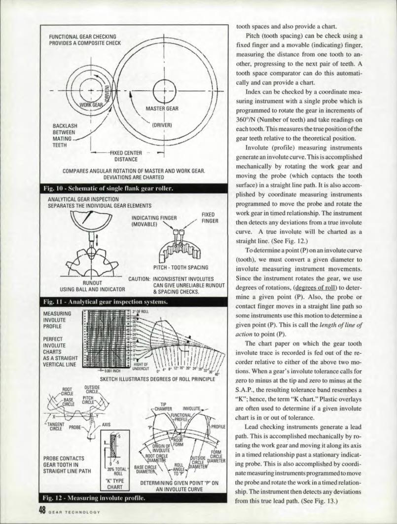
In the single f7.ank (fixed center distance)method, the master gear and work: gear aremounted on fixed center distance with back-lash. (See Fig. 10.) The master gear drivesthe work gear. The relative angular rotationof the master and the work are comparedand charted. This method can find the sameerrors as the dual flank: method and can al 0
detect angular velocity errors.Ana]ytica] Gear lnspection
Analytical gear inspection is used for check-ing the individual elements of a gear - runout,lead. involute, tooth spacing, tooth thickness, etc.
Runout can be checked with a master gear(See previous paragraphs on functional gearinspection). It can also be checked by indicatingover a ball or pin in a tooth space. progressing tothe next tooth pace. (See Fig. l I.) Some instru-ments. a tooth space comparator, for example,will inspect rucout by plunging a ball into the
J INDEX
DATUM ANGULA'R P'OSITION VARIATI'ON FR'OM DATUM P'OSITION
--- --
Fig. 7 - Pitch \ arialinn.
FUNCTIONAL GEAR INSPECTI'ON
FIXTURE MEASURES CENTERDISTANCE VA.RIATIONS
W'O~GEAR
I FIXED
DIAL"<, INDICATOR
. MASTER GEARFLOATS
1 REVOLUTION (360·' 'OFWORK GEAR.--
,,",va •• o •• oOOIi!'.OOi' '8
. I ~~.QltA~M~ETIrP~~~~ Ill§~Ng ==. .-.- . . . I MAXIMUM .
__ .. _ - - -. TOOTH . TOOTH·Tn-TODTHCOMPOSITE ' - COMPOSITE VARIATION
- VARIATION
360"/N---~- _.- -----_ ..- -- -- - ------. MINIMUM SETI)P MOUNTING DISIANCE
,0 o~. lal ,a, 4' 10 0 a 0 0 Go II 0.011 !D" DO, 0 ,00 I) '!IIi' 18, • II. I
Fig. 9 - {'lIart,,!' t~ pical gear tooth errors - \\ or!.: gl'al' rollerl \, ithmaster I!e<lr in dual Ilank fixture.
J U L Y I II. U G U s T 1 9 9 2 47
COMPARES ANGULAR ROTATION OF MASTER AND WORK GEAR.DEVIATIONS ARE CHARTED
,FUNCTIONAL GEAR CHECKINGPROVIDES A COMf'OS!ITE CHECK
!-\:-@
MASTER GEAR
,I /'(DRI~~
~
Fig. W " Schematic of singlt' llunk gear rnller.
.ANALYTICAL GEAR INSPECTIONSEPARATES THE INDIVIElUAL GEAR ELEMENTS
INDICATING FINGER ,,/ '::~~~R(MOVABLEI~ .. -
PITCHI· roOTH SPACING
CAUTION: INCONSISTENT INVOLUTESCAN GINE UNREUIABLE RUNOUT& SPACING CHECKS.
RUN OUTUSING BALL AND INDICATOR
Fig. II - \nal~ tical gem' invpcctiou s~St('I1I~,
MEASURINGINVOLUTEPROFILE
PERFECTINVOLUTE
I CHARTSAS A STRAIGHT
, VERTICAL LINE'
SKETCH 'ILLUSTRATES DEGREES OF ROLL PRINCIPLE
TIPCHAMFER INVOLUTE.-
·~FUNt:TIO~A.·L .PROFILEI
CIRCLE ~ -
-
5•• ;OTAL
ROLL"K'TYPECHART
P.ROBE CONTACTSGEAR TOOTH INSTRAIGHT LINE PATH
,48 (lEAR TECI'lNOLOGY
~----------------------------------------------------------
tooth spaces and also provide a. chart.Pitch (teeth spacing) can be check using a
fixed finger and a movable (indicating) finger,measuring the distance from one tooth to an-other, progressing to the next pair of teeth. Atooth space comparator can do th:is automati-cally and can provide a chart.
Index can be checked by a coordinate mea-suring instrument with a single probe which isprogrammed to rotate the gear in increments of3600JN (Number of teeth) and take readings Olll
each tooth ..This measures the true position of thegear teeth relative to the theoretical position.
Involute (profile) measuring instrumentsgenerate an involute curve ..This is accomplishedmechanically by rotating the work gear andmoving the probe (which contacts the toothsurface) in a straight Hue path. It is also accom-plished by cooordinate measuring instrumentsprogrammed to move the probe and rotate thework gear in timed relationship. The instrumentthen detects any deviations from a true involutecurve, A true involute win be charted as astraight line. (See Fig ..12.)
ToOdetermine a. point (P) on an involute curve(tooth), we must convert a given diameter toinvolute measuring instrument movements.Since the instrument rotates the gear, we usedegrees of rotations, (degrees .of roll) to deter-mine a given point (P). Also, the probe orcontact finger moves in a straight line path sosome instruments use this motion to determine agiven point (Pl. This is call the length of line ofaction to point (P).
The chart paper en which the gear toothinvolute trace is recorded is feci out of the re-corder relative to either of the above two mo-tions. When a gear's involute tolerance calls ferzero to minus at the tip and zero to minus at theS.A.P., the resulting tolerance band resembes a"K"; hence, the term UK chart ....Plastic overlaysare often used to determine if a given involutechart is in or out of tolerance,
Lead checking instruments generate a leadpath. This is accomplished mechanicajly by ro-tating the work gear and!moving it along its axisin a timed relationship past a stationary mdicat-ing probe. This is also accomplished by coordi-nate measuring instruments programmed to movethe probe and rotate the work in a timed relation-ship. The instrument then detects any deviationsfrom this true lead path. (See Fig. 13.)
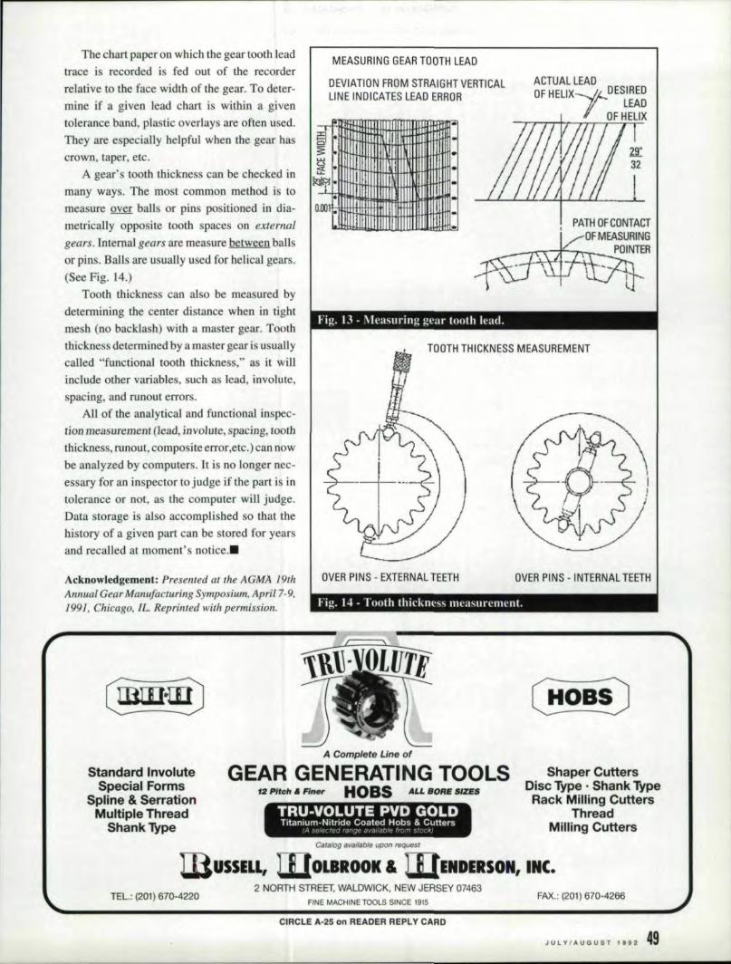
The chart paper on which the gear tooth leadtrace is recorded is fed out of the recorderrelative to the face width of the gear. To deter-mine if a given lead chart is within a giventolerance band, plastic overlays are often used.They are especially helpful when the gear hascrown, taper, etc.
A gear's tooth thickness can be checked inmany ways. The most common method is tomeasure over bans or pins positioned in dia-metrically opposite tooth spaces on externalgears. Internal gears are measure between ballsor pins. Balls are usually used for helicalgears.(See Fig. 14.,)
Tooth thickness can also be measured bydetermining the center distance when in tightmesh (no backlash) with a master gear, Tooththickness determined by a master gear is usuallycalled "functional tooth thickness," as it willinclude other variables, such as lead, involute,spacing, and mnout errors.
AU of the analytical and functional inspec-tiOll measurement (lead, j,nvoJure, spacing, tooththickness, runout, composite error,etc.) can nowbe analyzed by computers. It is no longer nec-essary for an inspector to judge if the part is intolerance or not, as the computer win judge.Data storage is also accomplished so that thehistory of a given part can be stored for yearsand recalledat moment's notice .•
Acknowledgement: Presented at the AGMA 19thAnnual Gear Manrl/acturillg Symposium, April 7-9,1991, Chicago, Il: Reprinted with permission.
MEASURING GEAR TOOTH L'EAD
oEVl'ATiIIlNI FROM STRA'lGHT VERTICALLINE INDIICATES LEAD ERROR
§I Ilol' rITttttftl.AAl-WlflltttITII~: :-i lltIttt:~' I-IJ;.I+lJHItftflHlIII·Q _I I
;2;•. rlllilTTlttttt++H~, iIit' 1tIH1rHHt111111··~.I I ..
." I
ACTUAL lEADOF HEUX-r ...• DESJ~E~
LEADOF HELIX
..
.. PATH OFCONTACTOFMEASIlJRING
POINTER
--- ---
Fig, 13 - Mcasurinu gear tooth lead, I
TQQTH THIICKNESS MEASUREMENT
lOVER PINS - EXTERNAL UETH OVER iPilNS - INTERNAL TEETH
Fig. I~ - Tooth thickness measurement.----------------
Stan,d'ardl Invo!luteSpecia'i F:orms
Spline &. SerrationMultiple Thread
Shank Type
.A ,Complete' tilJe of
TRU-VOLUTE PVD ,GOLDTrtaniurn-Nitride Coated Hobs & Cutters
I~l ....I, L ,Ie : ',,'I -It: d. i, ,1/ ....... //(1 r ,,! '" ".- ---
Shaper Cutt,ersD;isc Type ..Shank 'JYpeRac:k Milling Cutters
ThreadMiilling Cutters
UlUSSEL'L, LpJr'OL'BROOK & WENDERSON, INC.
GiEAR GENEIRATIING T,QOLS·'2 Pile" a. Rn.,. HOaS AU SOA.. SIZES
T:EL.: (201i) '670-42202 NORTH STREET. WALDWICK, NEW JERSEY 07463
FINE MACHINE TOOLS SINCE 19·15FAX.: (201) 670-4266
CIRCL'E A.,25 on READER REPLY CARD
JULY/AUGUST'992 4,9'