Gear Finishing by Shaving, Rolling and Honing, Part I · Gear Finishing by Shaving, Rolling &...
8
Gear Finishing by Shaving, Rolling & Honing - Part I John P. Dugas Nationa:1 Broach & Ma!chine Co. Mt CI,emens, IMI There are several methods available for irn- proving the quality of spur and helical gears following tile standard roughing operations of hobbing or shaping. Rotary gear shaving and eoll-finishing are done in the green or soft state prior to heat treating. These processes have the ability to modify the gear geometry to cornpen- sate for the distortionsthat occur during heat treatment. Gear honing is a particularly effec- tive method of removing nicks and burrs from the active profiles of the teeth after heat treat- ment. Combined with its ability to improve surface finish and make minor form correc- tions. the boning process is rapidly being ac· cepted as an operation through which many gears are processed following heat treatment. INVOLUTE PROFILE CHECKS ,001" AS HOBBED AS SHAVED LEAD CHECKS AS HOBBED AS SHAVED Fig. 1 • Improvement in pl'ofil'eand lead, S.7 NPD .20°, NPA, 3'.8S", P.D., crov ned shaved with stock removal of 0.011" over pins. 14 GEAR TECHNOLOGY The Rotary Gear Sbaving Process Gear shaving is a free-cutting gear finishing operation that removes small amounts of metal from the working surfaces of gear teeth .. It purpose is to correct errors in index, helix angle, tooth profile, and eccentricity (Fig. 1). The pro- cess also Improvesmoth surface finish and eliminates, by crowned tooth forms, the danger oftooth end load concentrations in service, Shav- ing provides for profile modifications that re- duce gear noise and increase a gear's load- carrying capacity, its factor of safety, and its service life. Gear finishing (shaving) is not to be confused with gear cutting (roughing), They are essentially different Any machine designed pri- marily for one cannot be expected to do both with equal effectiveness or with ,equal economy. Gear shaving is the logical remedy for the inaccuracies inherent in gear cutting. Uis equally effective as a control for those trouble ome dislortion caused by heat treatment The form of the shaving cutter can be reground to make profile allowance for different heat- treatment movements due to varying heats of steel, The shaving machine can be reset to make allowance for lead change in heat treatment. Rotary gear shaving is a production process that utilizes a high-speed steel, hardened and ground, ultraprecision shaving cutter. The cut- teris made in the form of a helical gear. It has gashes in the flanks of the teeth that act as the cutting edges. The cutter is meshed with the work gear in crossedaxe relation hip (Fig. 2) and rotated in both directions during the work cycle while the center distance is reduced incrementally. Simul- taneously, tile work is traversed back. and forth
Transcript of Gear Finishing by Shaving, Rolling and Honing, Part I · Gear Finishing by Shaving, Rolling &...

Gear Finishing byShaving, Rolling &
Honing - Part IJohn P. Dugas
Nationa:1 Broach & Ma!chine Co.Mt CI,emens, IMI
There are several methods available for irn-proving the quality of spur and helical gearsfollowing tile standard roughing operations ofhobbing or shaping. Rotary gear shaving andeoll-finishing are done in the green or soft stateprior to heat treating. These processes have theability to modify the gear geometry to cornpen-sate for the distortionsthat occur during heattreatment. Gear honing is a particularly effec-tive method of removing nicks and burrs fromthe active profiles of the teeth after heat treat-ment. Combined with its ability to improvesurface finish and make minor form correc-tions. the boning process is rapidly being ac·cepted as an operation through which manygears are processed following heat treatment.
INVOLUTE PROFILE CHECKS
,001"
AS HOBBED AS SHAVED
LEAD CHECKS
AS HOBBED AS SHAVED
Fig. 1 • Improvement in pl'ofil'eand lead, S.7 NPD .20°, NPA, 3'.8S", P.D.,crov ned shaved with stock removal of 0.011" over pins.
14 GEAR TECHNOLOGY
The Rotary Gear Sbaving ProcessGear shaving is a free-cutting gear finishing
operation that removes small amounts of metalfrom the working surfaces of gear teeth .. Itpurpose is to correct errors in index, helix angle,tooth profile, and eccentricity (Fig. 1). The pro-cess also Improvesmoth surface finish andeliminates, by crowned tooth forms, the dangeroftooth end load concentrations in service, Shav-ing provides for profile modifications that re-duce gear noise and increase a gear's load-carrying capacity, its factor of safety, and itsservice life. Gear finishing (shaving) is not to beconfused with gear cutting (roughing), They areessentially different Any machine designed pri-marily for one cannot be expected to do bothwith equal effectiveness or with ,equal economy.
Gear shaving is the logical remedy for theinaccuracies inherent in gear cutting. Uis equallyeffective as a control for those trouble omedislortion caused by heat treatment
The form of the shaving cutter can be regroundto make profile allowance for different heat-treatment movements due to varying heats ofsteel, The shaving machine can be reset to makeallowance for lead change in heat treatment.
Rotary gear shaving is a production processthat utilizes a high-speed steel, hardened andground, ultraprecision shaving cutter. The cut-teris made in the form of a helical gear. It hasgashes in the flanks of the teeth that act as thecutting edges.
The cutter is meshed with the work gear incrossedaxe relation hip (Fig. 2) and rotated inboth directions during the work cycle while thecenter distance is reduced incrementally. Simul-taneously, tile work is traversed back. and forth

across the width of the cutter. The traverse pathcan be either parallel or diagonal to the workgear axis, depending on the type of work gear.the production rate, and finish requirements.The gear shaving process can be performed athigh production rate . It removes material in theform of fine hair-like chips.
Machines are available to shave external spurand helical gears up to Sm (200") in diameter.Other machines are also available for shavinginternal spur or helical. gears. For be t resultswith shaving. the hardness of the gear teethshould not exceed 30 Rockwell C cale. U stockremoval is kept to recommended limits and the
gears are properly qualified, the shaving processwill finish gear teeth in the 3.6- to 2.S-m (7-tolO-pitch) range to the following accuracies: in-volute profile, 0.005 mm (0.0002 in); tooth-to-tooth spacing, 0.0075 nun (0.0003 in); lead orparallelism. 0.005 mm (0.0002 in.)
In any event, it should be remembered thatgear shaving can remove from 65% to 80% of theerrors in the bobbed or shaped gear. It will makea good gear better ..The quality of the sha ved gearis dependent to a large degree on having goodhobbed or shaped gear teeth.
Excellent surface finish is achieved with gearshaving. A value of approximately 2511. in is thenormal finish achieved with production gearshaving, although much finer finishes are pos-sible by slowing theproee s. In some cases,shaving cutters will finish up to 80,000 gearsbefore they need harpening, They many gener-ally be sharpened from four to ten times,
The shaving process offer attractive advan-tages in theabihty to modify the tooth form, If acrowned tooth form or a tapered tooth form aredesired to avoid end bearing conditions, thesecan be 'easily provided by shaving.
If modifications are desired in the involuteprofile, these can be made by unable modifica-tio ns in the grou ed cutter tooth form. U a crownedtooth form or a tapered tooth form are desired toavoid end bearing conditions, these can be easilyprovided by shaving.
Modification in the involute profile can bemade by suitable modifications in the groundcutter tooth form. If heat-treatment distortionscan be controlled toa minimum, t.he rno t inex-pensive way to produce an accurate, quiet, high-performance gear is to specify hobbing followedby gear shaving .. Tille shaving process has a
Fig ..1 - Crossed axes me "bing of shavingcutter andwork gear..
Fig ..3 - Assortment of rotary gear shaving cutters ..
variety of standardized production equipmentavailable, ranging from hand loading to fullyautomatic loading and unloading,
Basic PrlnelplesThe rotary gear shaving process is based on
fundamental principles. This process uses agashed rotary cutter in the form of a helical gearhaving a helix angle different from that of thegear to be shaved (Fig. 3). The axes of cutter andgear are crossed at a predetermined angle dur-ingthe shaving operation. When cutter and workgear are rotated in close mesh. the edge of eachcutter gash. as it moves over the urface of awork gear tooth, shaves a fine, hair-like chip.The finer the cut, the less pressure is requiredbetween tool and work, eliminating the len-dency to cold work the surface metal of the
,John P. Dugasis the Sales Manager (II
National Broach & Ma-chine Co .. Mr. Clemens.Ml. He is the author ofnumerous articles OJI
gearing subjects.
!,lARCH I APRil 1~92 15

Fig..4 - 12" Rotary gear shaving machine ..
work gear teeth.This process is performed in a shaving ma-
chine (Fig. 4), which has a motor-driven cutterhead and a reciprocating work table. The cutterhead is adjustable to obtain the desired crossedaxes relationship with the work. The work car-ried between live centers is driven by the cutter.During the shaving cycle, the work is recipro-cated parallel to its axis across the face of thecutter and up-fed an increment into the cutterwith each stroke of the table. This shavingcycle(conventional) is one of several methods.
The Crossed Axis Principle - To visual:ize thecrossed axis principle, consider two parallel cyl-inders of the same length and diameter (Fig. 5).When brought together under pressure, theircommon contact surface is a rectangle having alength of a cylinder and width that varies withcontact pressure and cylinder diameter.
When one of these cylinders is swung aroundso that the angle between its axis and that of the
PARALLEL DIAMETER CONTACT
~aI
CROSSED-AXES CONTACT
RIGHT ANGLE CONTACT
Fig. 5 - Contact between cylinders changes as crossed axes are varied.
16 GEAR TECHNOLOGY
other cylinder is increased up to 90°, their com-mon plane remains a parallelogram, but its areadecreases as the axial angle increases. The sameconditions prevail when, instead of the two plaincylinders, a shaving cutter and a work gear aremeshed together. When the angle between theiraxes is from 10 to 15°, tooth surface contact isreduced and pressure required for cutting issmall. As the work gear is moved away axiallyfrom the point of intersection backlash devel-ops. Conversely. as it is returned to the point ofaxial intersection, backlash decreases until thetwo members engage in tight mesh with theteeth ofthe cutter wedging between those ofthe work gear. Thus, each succeeding cuttingedge sinks deeper into the work gear toothuntil the point of axial intersection is reached.
For shaving, the cutter and work gear axes arecrossed at an angle usually in the range of lO~o15° or approximately equal to the difference intheir helix angles ..
Crossing of the axes produces reasonably uni-
form diagonal sliding action from the tips of theteeth to the roots. This not only compensates forthe nonuniform involute action typical of gearsin mesh on parallel axes, but also provides thenecessary shearing action for stock removal.
Relationship Between Cutting and GuidingAction - Increasing the angle between cutter andwork axes increases cutting action, but, as thisreduces the width of the contact zone, guidingaction is sacrificed. Conversely, guiding actioncan be increased by reducing the angle of crossedaxes, but at the expense of cutting action.
Preparation Prior to Shaving - The first con-sideration in manufacturing a gear is to select thelocating surfaces and use them throughout theprocess sequence. Close relationship betweenthe locating surface and the face of the gear itselfmust be held, Otherwise, when the teeth are cutand finished with tooling that necessarily con-tacts the gear faces, the teeth win be in animproper relationship with the locating or re-lated surface on which the gear operates. Gearsthat locate on round diameters or spline teethmust fit the work arbors closely, or these criticalhole-to-face relationships will be destroyed.
Typical manufacturing tolerances for gearblanks prior to cutting of the teeth are shown inTable 1.
Once the gear blank has been manufactured,it is necessary to cut the gear teeth. The most

common method today for rough-culling gearteeth axe hobblng Bindshapercutting. Of primaryconcern 10 the shaving cutter manufacturer ithe fillet produced by the roughing operation.The lip . of the shaving cutter teeth must notcontact the gear root fillet during the shavingoperation. If such contact does occur. excessivewear of the cutter res 1.1 Its, and. the accuracy of theinvolute profile i affected.
The shaving cutter just fini hes the gear toothbelow its active profile. Thu • the height of the
fill lei should not exceed the lowest point ofcontact between the having cutter teeth and theteeth on the work gear.
Protuberance-type hobs and simper cuttersare often used priorto having to produce a slight is the direction of reciprocation (traverse) oftheundercut or relief ncar the base of the gear tooth. work through and under the tool.Thi method a ures a smooth blending of the Axial or Conventional - Axial shaving isshaved tooth profile and the un haved tooth widely \I ed in low- and medium-producnonfillet, as well as reduce sn3ving cutter tooth tip operation (Fig. 7). It is the mosteconomicalwear (Fig. 6). The amount nf undercut produced method for shaving wide-face-width gears. Inby the protuberance-type tool hould be made thi method, the traver se path i along theaxis offor the thin end of [he tooth. The position of the the work gear. The number of stroke may varyundercut should be uch that its upper margin due to the amount of stock to be removed. Themeets the involute profile at a point below its length of traver, e is determined by the facecontact diameter. width of the work. For best results, thelength of
Shaving Stock - The amount of stock removed traverse should be approximately 1.6 mm ([/during the shaving process isakey to its succe s- 16") greater than the face width of the work.ful applicstion. Sufficient toek hould be re-
Table I.• TypicollGeor Blank Tol'ell'ilnces
Blank 'F"". Hole Hole Hole 0,0. 0,0.Dia. RUOOOl Size Taper Roundness In.- RunoutID_ In, In. lo.lln. In.- Max Max lo.
Up 10 .1. 0.0003- 0.0003· 0.0002- 0.0002- 0.003 0.003l-in. Thiel, O,I)OO1i 0.0006 0.000] 0.0003
1104. up10 I-In Q,(I(){)4. 0.0005- 0.0002- 0.0003 - 0.005 0.00511rick 0,0008 0.00 I 0.0003 0.0005
4 108 0.0006· 0.1)00&· 0,0002- 0.0004- 0.005 0.007OJI0I2 (1.0012 0.0003 0.0006
811012 (1.001- 0.001- 0.0002- 0.0005- 0.005 0.008o.(m 0.00 15 0.0003 0.0007
moved [0 penni! correction of errors in thepre haved teeth. However, if too much stock isremoved ..cutter life and part accuracy are effec-tively reduced.
Table 2 shews the recommended amounts of
stock to be removed during shaving and thecortesponding amount of undercut required.
Shaving Metilods - There are four basic meth-ods for rotary having of eternal pur andheli-cal gear: (W)axial or conventional. (2) diagonal.(3) tangential or underpass and (4) plunge, Theprincipal diUerence among the various method
r: PRE.S. HAVEDI r-SHAVEO
POINT OF INTERSECTIONOF PRE·SH ..WED PROFILEWITH PROTUBERANCE UNDERCUT
-- FORM DIAMETER
, .ooo~ GREATER THAN SHAVING STOCK- /' .001 (DEPENDING ON DlA. PITCH)
POINT OF MAXIMUM UNDERCUT(MAXIMUM HEIGHT OFROOT FILLET) TYPICAL PROTUBERANCE TYPE
ROOT FILLET BASIC HOB TOOTH FORMAS GENERATED BV PRE·SHAVING TOOL
Fig..·6- ndereut produced by pr,otuberance hob and basic bob to.oth form.TabJe n -Recommeaded Shaving Stock and' ndercnt For Pre-shavedGcaxs
Dia:~l:1~'lcbShuvi~ Stock TollI.ll'U ndercut
(In. per Si e of TOOLh) lin. per Side of Tooth)
2104 0.0015 to 0.0020 R0025 10 0 0030
5106 0.0012 [00.0018 0.0023 10 0.0028
710110 0.0010 to 0.0015 0.001:5 100.11020
lito .14 0 ..0008 ro 0.00 13 0.0012 tu 0.001.7
161018 0.0005 to 0.00 I0
20104H 0.0003 10 0.0008
521072 0,0001 100.0003
FULL STROKE
CROSSEDAXES ANGLE I
I~~I!t"""=--t-
~ : GEARI TAAVEIRSE: PATH
"--+--',..- -- ....
MARCH , AIPRI~ 111112 Ill'

SHAVING CUnE
WORK GEIl,
Fig. 8,• Rocking table action (or crowning during convendonal shaving.
TRAVERSEANGLE GEAR
CUTTER
Fig. 9 • Diagonal shaving ..
GEARTRAVERSEPATH
FULLSTROKEANGLE
CROSSEDAXES ANGLE
GEAR
CUTTER
TRAVERSE
Fig. 10 • Tangential shaving (underpass),
CUTTER
GEAR
CROSSEDAXES
!Fig.n-Plunge shaviling.
work face. In axial shaving. in order to inducelead crown, it is necessary to rock the machinetable by use of the built-in crowning mechanism(Fig. 8).
Diagonal - In diagonal shaving, the traversepath is at an angle to the gear axis (Fig. 9).Diagonal shaving is used primarily in medium-and high-production operations.
18 GSAR TECHNOLOGY
By use of this method, shaving times arereduced by a, much as 50%. In diagonal shaving,the urn of the traverse angle and the crosses axesangle is limited to approximately 55°, unlessdifferential-type serrations are used; otherwise,the serrations will track. The relative face widthsofthe gear and the shaving cutter have an impor-tantrelanonshipwith the diagonal traverse angle.A wide-face-width work gear and a narrow shav-ing cutter restrict the diagonal traverse to a smallangle. Increasing the cutter face width permitsan increase in the diagonal angle. Crowning thegear teeth can be accomplished by rocking themachine table, provided the sum of the traverseangle and crossed axes angle does 110t exceed5SO. When using high diagonal angles, it ispreferable to grind a reverse crown (hollow) inthe lead of the shaving tool.
In most cases, the diagonal traverse angle willvary from 30 to 60° to obtain optimum condi-tions of cutting speed and work gear quality.
With diagonal traverse shaving, the center-line of crossed axes is not restricted to a.singleposition on the cutter asin conventional shaving,but is migrated across the cutter face, eveningout the wear. Consequently, cutter life is ex-tended. Although conventional shaving requiresa number of table strokes,each with its incre-ment of upfeed, diagonal shaving of finer-pitchgear may be done in just two strokes with noupfeed and a fixed center distance between cut-ter and work. Au automatic upfeed mechanismon the shaving machine rnaterially enlarges thescope of diagonal. shaving by making it availablefor multistroke operations. This device feeds thework into the cutter in a series of small incre-ments, synchronized with table reciprocation.Removing tock from the workgear in a series ofsmall increment. instead of two large incre-ments. further increases cutter life. It also makesthe process feasible for gears requiring morestock removal than can be handled ana two-stroke cycle. When upfeed is completely auto-matico there can be no danger of an error inselecting feed rate .,Inasmuch as the cycle startsand stops in a position of maximum backlash,loading and unloading can be very fast.
Tan~ential or Underpass - In the tangential.(underpass) method of shaving (Fig ..10), thetraverse path of the work is perpendicular to itsaxis .. Tangential shaving is used primarily i.11high-production operations and is ideally suited

for shaving gears with restricting shoulders.When using this method. the serrations on thecutter must be or the differential type. Also. theface width of the cutter must be larger than thatof the work gear.
Plunge - Plunge shaving is used in high pro-duction operarlons (Fig. 11). In this method, thework gear j fed into the shaving cutter with notable reciprocation. The shaving cutter mu I
have the differential-type erration or cuttingaction will be impaired. To obtain a crownedlead on the work. it is nece sary to grind into thehaving cutter lead a reverse crown or hollow. In
all cases of plunge shaving, tile face width of theshaving tool must be greater than that of thework gear. The primary advantage of plungeshaving is a very short cycle time.
Shaving Internal' Gears -Internal gears canbe shaved on special machines in which thework drives the cutter (Fig. 12), or by internalcutter head attachments on external shavingmachines (Fig. 13).
Because of tile crossed axes relation hip be-tween the cutter and the workgear in internalhaving, the cutter require a slight amount of
crown in the teeth to avoid interference with thework gear teeth. Crowning ofthe teeth on gearsover 19 mm (3/4") wideis best achieved by arocking action of the work head similar to therocking table action with external gear shaving.
When internalgear are.19 mm (3/4") wideand under, or should Interference limit the workreciprocation and crossed axes angle, plungeshaviag can be applied. The cutter is providedwith differential errations and plunge-fed up-ward into the work. If lead crown is desired onthe work gear, a reverse crowned cutter is usedwith the plunge feed shaving process.
The Shaving CutterRotary having cutter are high-precision.
hardened and ground, high-speed steel generat-ing tools held to Class A and AA tolerances inall principle elements (Fig. 14). The gashe inthe having cutter extend 'the fun length of thetooth, terminating in a clearance space at thebottom. The e clearance spaces provide unre-stricted channel for a constant flow of coolantto promptly di pose of chips. They also permituniform depth of serration penetration and in-crease cutter life.
The shaving cutter i rotated at high speedsup to 122m (400 and more surface ft.) per minute.
Fig. 1.3- Ex~.ernal shaver wHit internal. cutter headattachment,
Feed is fine and the tool contact zone is re-stricted. Cutter life depends on . everal factor :operating peed. feed ..material and hardne s ofthe work gear, its required tolerances, type ofcoolant, and the size ratio of culler to work gear.
Design - Rotary gear shaving cutters are de-signed much like other helical involute gears.The serrations on the tooth profiles, in conjunc-tion with the crossing of the axes of the cutter andthe work gear, make it a cutting tool. In design-ing rotary gear shaving cutters, the following aresome of the points that must be considered:
I. Normal diametral pitch and normal pres-sure angle must be the same as those of the gearsto be shaved.
2. Helix angle is chosen to give a desiredcrossed axis angle between the cutter and work.The crossed axis angle is the difference betweenthe helix angles of the shaving cutter and workgear. The desired range is from 5 to 1.5°.
MARCH I APRILI~92 19
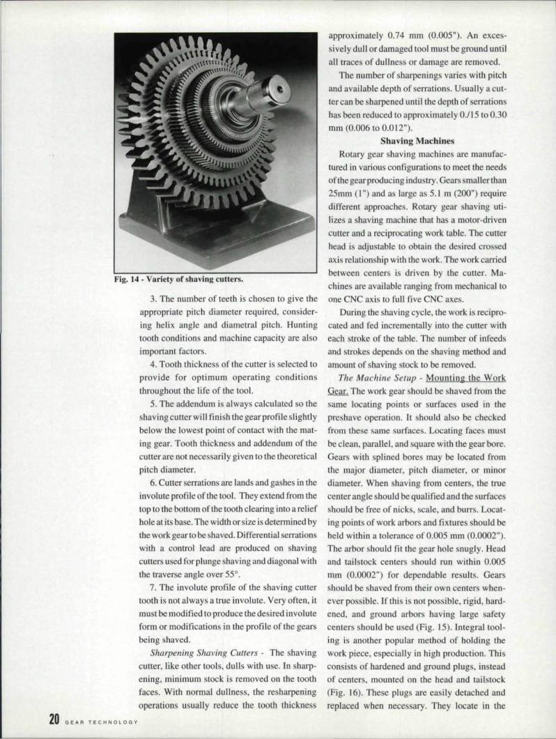
Fig. M·· Vari.ety ofshaviag cutters.
3. The number of teeth is chosen to give theappropriate pitch diameter required, consider-inghelix angle and diarnetral pitch. Huntingtooth conditions and machine capacity are alsoimportant factors.
4. Tooth thickness of the cutter is selected toprovide for optimum operating conditionsthroughout the life of the tool.
5. The addendum is always calculated so theshaving cutter will finish the gear profile slightlybelow the lowest point of contact with the mat-ing gear. Tooth thickne. and addendum of thecutter are not necessarily given to the theoreticalpitch diameter.
6. Cuner . errations are lands and gashes in theinvolute profile of the tool. They extend from thetop to the bottom of the tooth clearing into a reliefhole at its base. The width or size is determined bythe work gear to be shaved. Differential serrationswith a control lead are produced on shavingcutters used for plunge shaving and diagonal withthe traverse angle over 55°.
7. The involute profile of the shaving cuttertooth is not always a true involute. Very often, itmust be modified to produce the desired involuteform or modifications in the profile of the gearsbeing shaved.
Sharpening Shaving Cutlers - The shavingcutter, like other tools, dulls with use. In sharp-ening, minimum stock is removed on the toothfaces. With normal dullness, the resharpeningoperations usually reduce the tooth thickness
,20 C! EAR TEe H N a LOG Y
approximately 0.74 mm (0.005"). An exces-sively dull or damaged tool must be ground untilall traces of dullness or damage are removed.
The number of sharpenings varies with pitchand available depth of serrations. Usually a cut-ter can be sharpened until the depth of serrationshas been reduced to approximately 0.115 to 0.30111m (0.006 to 0.012").
Sbaving MachinesRotary gear shaving machines are manufac-
tured in various configurations to meet the needsof the gear producing industry. Gears smaller than25mm (I. ") and as large as 5.1. m (200") requiredifferent approaches. Rotary gear shaving uti-lizes a shaving machine that has a motor-drivencutter ami a reciprocating work table ..The cutterhead is adju table to obtain the desired crossedaxis relationship with the work. The work carriedbetween centers is driven by the cutter. Ma-chines are available ranging from mechanical. toone CNC axis to full five CNC axes.
During the shaving cycle, the work is recipro-cated and fed incrementally into the cutter witheach stroke of the table. The number of infeedsand strokes depends on the shaving method andamount of shaving stock to be removed.
The Machine Setup - Mounting the Work:Gear ..The work gear should be shaved from thesame locating points or surfaces used in thepreshave operation. It. should also be checkedfrom these same surfaces ..Locating faces mustbe clean, parallel, and square with the gear bore.'Gears with splined bores may be located fromthe major diameter, pitch diameter, or minordiameter. When shaving from centers, the truecenter angle should be qualified and the surfacesshould be free of nicks, scale, and burrs. Locat-ing points of work arbors and fixtures should 'beheld within a tolerance of 0.005 mm (0.0002").The arbor should fit the gear hole snugly. Headand tailstock centers should run within 0.005mm (O.OOO2") for dependable results. Gearsshould be shaved from their own centers when-ever possible. If this is not possible, rigid, hard-ened, and ground arbors having large afetycenters should be used (Fig. 15). Integral tool-ing is another popular method of holding theworkpiece, especially in highproduction, Thisconsists of hardened and ground plugs, insteadof centers, mounted on the head and tailstock(Fig. 16). These plugs are easily detached andreplaced when nece sary. They locate in the

bore and against the face of'the gear. It is there-fore essential that the gear faces be square andbore tolerances held to assure a good slip fit onthe plugs ..
Mounting the Cutter. Great care is required inhandling the shaving cutter to avoid any acci-dental contacts 'between its teeth and other hardobjects. The slightest bump may nick a tooth.Until the cutter is placed on its spindle it shouldlie flat and away from other objects. The cutterspindle and spacers should be thoroughly cleanedand the spindle checked before the cutter ismounted. The spindle should run within a 0.005mm (0.0002") on the 0.0. and 0.0025 mm(0.0001 ") on the flange full indicator reading.
After mounting, the cutter face should beindicated to check mounting accuracy. Facerunout should not exceed 0.02 mm (0.0008") fora 30.5-em (I 20") cutter; 0.0] 5 mm (0.0006") fora 23-cm (9") cutter; or 0.10I mm (0.0004") for aI8-cm (7") cutter.
Feeds and Speeds. Shaving cutter spindlespeeds will vary with the gear material hardness,finish. and size of part. Normally, when using aI8-em (7") cutter on a 2.5-m (lO-pitch) gearhaving a 7.6-cm (3") pitch diameter, spindlespeed will be approximately 200 r/min; or, whereusing a 23-cm (9")cuUer, 1.60r/rnin. This speedfigured on the pitch circle is approximately 122surface ill (400 surface ft) per minute and thisgenerally produces good results.
The following are formulae for determiningcutter and gear speeds (r/min):Cutter r/min ;;;;:desired surface speed per min
cutter diameter x 1t
Gear rlmin;;;;:cutter r{min x number of teeth in cutter
number of teeth in gear
For conventional shaving. about 0.25 mm(0.010") per revolution of the gear is considereda good starting point and becomes a factor in thefoUowing formula:
Table feed rate [mmlm:in (in.lrnin)] :::::0.25 (0.010) x 'Gear r/rnin
For diagonal shaving ,an "effecti ve feed rate" ofappro imately LOmrn (0..0.40.") per revolution ofgear is considered a good starting point. Effec-tive feed rate is the rate of the speed at which thepoint ofcrossed axes migrates across tbe face ofthe gear and having cutter ..The following is the
BASIC PLUG·CLJP
FLANGED PLLJG-CLJP
Fig. IS- Ty-pical. hardened and ground work-holding arbors.
.-"~-",,",,,"r- -""\III~
fI,.......-~-t:LJ __ J)
INTEGRAL PLUG·CUP INTEGRAL EXPANDING
Fig. 1·6- Integral work-holding arbors.
formula for determining the table traverse rate(in.lmin) 10produce a] .O-mm (0.040") effectivefeed rare:
Table traverse rate [mmlmin (in.zminj]«1.0 mmc(0.040") x Gear r/min.
R f
Rf = sine traverse angletangent crossed axes angle
cosine traverse angle
+
These suggested feed rates may be varieddepending on indi vidual operating conditions. Ifhigher production is desired, the table feed ratecan be increased, but this may result in somesacrifice of the quality of tooth finish. Wheresurface finish is very important.as w:ith aviationand marine gears, table feeds are reduced belowthe amounts indicated. In some ca es (notably.large tractor applications), feeds considerably inexcess of those indicated are used. I.From Dudley's Gear Handbook. Znd ed. DennisP. Townsend. ed., ©1991 by McGraw-Hill. Re-printed by permission of McGraw-Hill Publish-ing Co.
This is the conclusion of Part 1. Part llof thisarticle, which will run in our next issue, willcover gear roll-finishing and rotary gear honingof both shaved and ground gears.
t.I " R CHI It P R I L 1 992 21