
Gear clamping with the HAINBUCH system: O.D. … · Gear clamping with the HAINBUCH system: ... as...
16
Gear clamping with the HAINBUCH system: O.D. clamping I.D. clamping
Transcript of Gear clamping with the HAINBUCH system: O.D. … · Gear clamping with the HAINBUCH system: ... as...
Gear clamping with the HAINBUCH system:
O.D. clamping
I.D. clamping
Broschüre Gear Industry US_final.indd 1 30.08.2011 16:41:22
2 America
Content
Who is HAINBUCH?
3
Main gear clamping possibilit ies
I.D. clamping 4
O.D. clamping - with adaptat ions for quick change from O.D. to I.D. 6
Solut ions
Gear clamping examples 10
Broschüre Gear Industry US_final.indd 2 30.08.2011 16:41:29

3America
profileTradit ion is good. Combined with innovat ion it is even better. For 60 years we have been constant ly developing new clam-ping solut ions focusing on your wants and needs. Set-up t imes and cost savings, flexibility, product ivity, energy efficiency, and security – all are desired from clamping solut ions. Our products deliver these essent ials. Included are CE cert ificat ion, and for-mal commitments to minimize environmental impact as well as exemplary corporate and social conduct. This is us and what we owe to you.
HAINBUCH – as flexible as your requirements!
Key advantagesHAINBUCH designs, develops and produces different
clamping tools that are simple and better Third-generat ion family business The company was founded in 1951 More than 500 employees worldwide 3 nat ional locat ions 8 internat ional subsidiaries [China, France, Great Britain,
Italy, Sweden, Slovakia, Thailand, USA] Nearly 40 agencies worldwide
Who is HAINBUCH?
Broschüre Gear Industry US_final.indd 3 30.08.2011 16:41:30
4 America
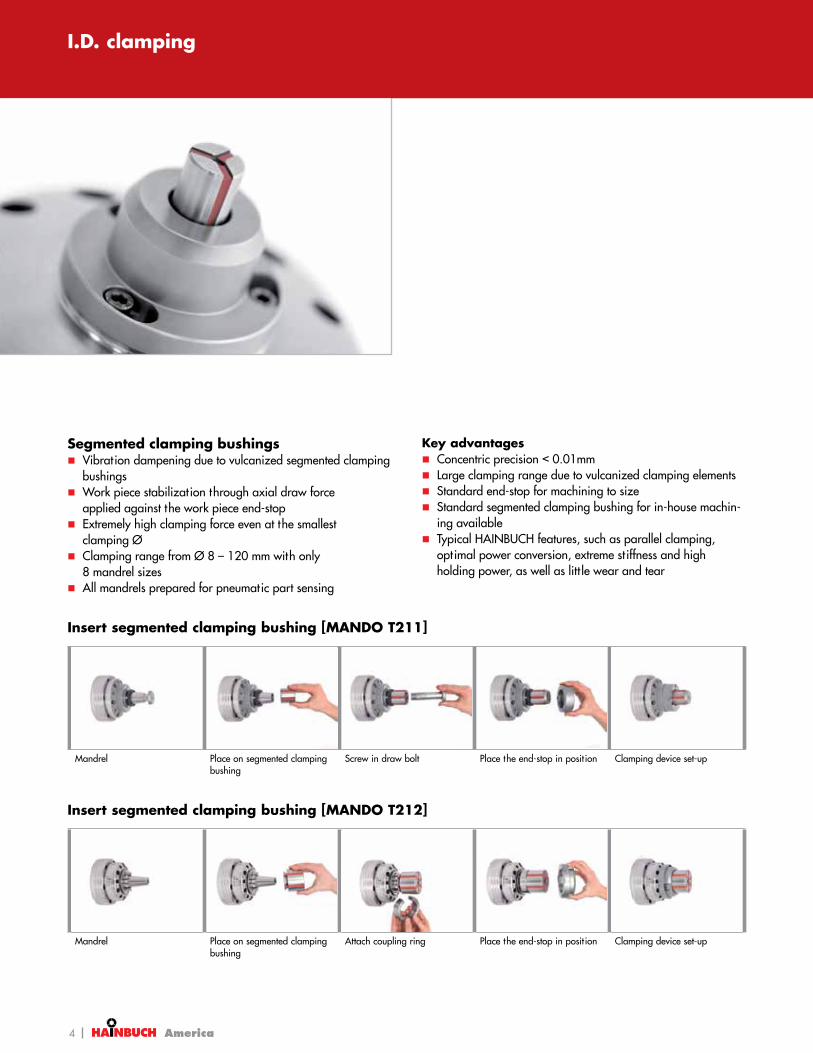
I.D. clamping
Insert segmented clamping bushing [MANDO T211]
Mandrel Place on segmented clamping bushing
Screw in draw bolt Place the end-stop in posit ion Clamping device set-up
Insert segmented clamping bushing [MANDO T212]
Mandrel Place on segmented clamping bushing
Attach coupling ring Place the end-stop in posit ion Clamping device set-up
Segmented clamping bushings Vibrat ion dampening due to vulcanized segmented clamping
bushings Work piece stabilizat ion through axial draw force
applied against the work piece end-stop Extremely high clamping force even at the smallest
clamping Ø Clamping range from Ø 8 – 120 mm with only
8 mandrel sizes All mandrels prepared for pneumatic part sensing
Key advantages Concentric precision < 0.01mm Large clamping range due to vulcanized clamping elements Standard end-stop for machining to size Standard segmented clamping bushing for in-house machin-
ing available Typical HAINBUCH features, such as parallel clamping,
opt imal power conversion, extreme st iffness and high holding power, as well as litt le wear and tear
Broschüre Gear Industry US_final.indd 4 30.08.2011 16:41:33

5America
I.D. clamping
Standard segmented mandrels at a glance
MANDO T211 in detail
Designation
1 Spindle flange suitable for all standard mandrel sizes2 Torsional safety3 Integrated ejector pins for forced opening of the clamping bushing4 Torsional safety for segmented clamping bushing5 Standard end-stop for machining to size6 Draw bolt [with safeguard against spinning out of segmented
clamping bushing at empty clamping]7 Segmented clamping bushing made of case-hardened steel
[60 HRC]
12
34
5
6
7
MANDO T212 in detail
Designation
1 Spindle flange suitable for all standard mandrel sizes2 Torsional safety3 Trimming sleeve for SAD segmented clamping bushings4 Torsional safety for segmented clamping bushing5 Installat ion aid, recommended for vert ical machines from mandrel
size 2 on6 Segmented clamping bushing made of case-hardened steel
[60 HRC]7 Coupling ring for fast changing of the segmented clamping
bushing8 High st iffness through one-piece crown coupling
MANDO T211 MANDO T212
Descript ion With draw bolt Without draw bolt –Sizes 0, 1, 2, 3, 4 XXS, XS, S, 0, 1, 2, 3, 4 –Clamping range of all sizes [mm] 20 – 120 8 – 100 –
374
Advantages Form-compensat ing segmented clamping bushing on request
Clamping range from Ø 20 – 120 mm with only 5 mandrel sizes
Clamping without draw bolt, ideal for blind bores
Clamping range from Ø 8 – 100mm with only 8 mandrel sizes
Custom solut ion opt imally tailo-red for your requirements
333 333
Standard Special segmented mandrels
1 2
34
5
678
Broschüre Gear Industry US_final.indd 5 30.08.2011 16:41:40

6 America
Clamping device
Rotating
Clamping element
Adaptation clamping device
TOPlus chuck
Clamping head –O.D. clamping
MANDO Adapt mandrel – I.D. clamping
Jaw adapter – clampingin front of the chuck
SPANNTOP chuck
MANOK plus manual stat ionary chuck
TOROK manual chuck
HYDROK hydraulic stat ionary chuck
Circumferent ial clamping3 different versions: For raw mate-rial, precision machining and for in-house machiningAn abundance of profile clamping possibilit iesCoolant-resistant rubber-metal con-nect ion, prevents chips in the chuckIn stock
Quick change-over from O.D. to I.D. clamping without indicat ing due to CENTREX interfaceConcentricity < 0.00 5mm between chuck taper and mandrel taper5 different mandrel sizesClamping range Ø12 – 100mmAvailable with and without draw boltIn stock
Approximately double the clamping Ø can be realizedDrilling and milling between the jawsInstallat ion and removal with tapered bolts – without changing fixtureLoading plug for in-house machining of the soft jaws
Stationary
The HAINBUCH modular system
O.D. clamping
Broschüre Gear Industry US_final.indd 6 30.08.2011 16:42:01

7America
Mandrel adaptions Changing over from O.D. clamping to I.D. clamping, without changing the clamping device? No problem! With MANDO Adapt, just place the mandrel in the mounted clamping device. In this process the mandrel engages in the coupling of the clamping device via a sophist icated mechanism, where the clamping head usually engages. A great t ime-savings solut ion, not to ment ion that MANDO Adapt is very attract ive with extreme rigidity and precision. Concentricity of 0.005 mm between chuck taper and mandrel taper, and for stat ionary clamping devices repeatability of 0.003 mm can be achieved. And best of all, this can all be accom-plished without indicat ing.
The MANDO Adapt is available in 3 variants: T211 – Clamping with pull-back effect and draw boltT212 – Clamping with pull-back effect without draw boltT812 – Clamping without pull-back effect without draw bolt
Ingeniously simple and effective, genuine HAINBUCH!
Key advantagesExtremely fast conversion without disassembling the base
clamping device [2 min.] Vibrat ion dampening due to vulcanized segmented clamping
bushings Extremely high clamping force even at at the smallest
clamping Ø Large span range due to vulcanized clamping elements Standard end-stop for machining to size Standard segmented clamping bushing for in-house machin-
ing available Typical HAINBUCH features, such as parallel clamping,
opt imal power conversion, extreme st iffness and high holding power, as well as litt le wear and tear
O.D. clamping
Broschüre Gear Industry US_final.indd 7 30.08.2011 16:42:06

8 America
MANDO Adapt at a glance
MANDO Adapt T211 MANDO Adapt T212 MANDO Adapt T812
1
2
4
5
6
3
Descript ion Mandrel-clamping-device with draw bolt
Mandrel-clamping-device without draw bolt
Mandrel-clamping-device without draw bolt
Sizes 0, 1, 2, 3, 4 XS, S, 0, 1, 2, 3, 4 XS, S, 0, 1, 2, 3, 4Clamping range of all sizes [mm] 20 – 120 13 – 100 13 – 100Variants SE [hexogonal], RD [round] SE [hexagonal], RD [round] RD [round]Actuat ion Draw Draw Pressure
374
Advantages Form-compensat ing segmented clamping bushings on request
Clamping range from Ø 20 – 120 mm with only 5 mandrel sizes
Work piece stabilizat ion through axial draw force applied against the work piece end-stop
Clamping without draw bolt, ideal for blind bores
Clamping range from Ø 13 – 100 mm with only 7 mandrel sizes
Work piece stabilizat ion through axial draw force applied against the work piece end-stop
Clamping without draw bolt, ideal for blind bores
Clamping range from Ø 13 – 100 mm with only 7 mandrel sizes
Pure radial clamping, no pull-back against the work piece end-stop. Ideal for pick-off from the main spindle
333 333
Change-over to mandrel adaptation T211 [2 min.]
Remove clamping head Insert MANDO Adapt T211 Install segmented clamping bushing
Screw in draw bolt Clamping device set-up
Change-over to mandrel adaptation T212 [2 min.]
Insert MANDO Adapt T212 Install segmented clamping bushing
Attach coupling ring Place on trimming sleeve/end-stop
Clamping device set-up
O.D. clamping
Broschüre Gear Industry US_final.indd 8 30.08.2011 16:42:10

9America
MANDO Adapt T211 SE in detail
Designation
1 CENTREX system for ultra precise usage without adjustment2 Coupling: Mandrel locks automatically when the draw bolt is
assembled3 Mounting screws for fast change4 Integrated forced release of the clamping bushing5 Torsional safety for segmented clamping bushing6 Standard end-stop for machining to size7 Draw bolt8 Segmented clamping bushing made of case-hardened steel
[60 HRC]
MANDO Adapt T212 SE in detail
Designation
1 CENTREX system for ultra precise usage without adjustment2 Coupling: Mandrel is locked via separate key3 Mounting screws for fast change4 Trimming sleeve for machinable [SAD] segmented clamping
bushings5 High st iffness through one-piece crown coupling with integrated
driver for segmented clamping bushing6 Segmented clamping bushing made of case-hardened steel
[60 HRC]7 Coupling ring for fast change of segmented clamping bushing
MANDO Adapt T812 RD in detail
Designation
1 Bayonet locking mechanism2 CENTREX system for ultra precise usage without adjustment3 Mounting screws for fast change4 Coupling ring for fast change of segmented clamping bushing5 Standard end-stop with integrated coupling guide for in-house
machining6 Segmented clamping bushing made of case-hardened steel
[60 HRC]
O.D. clamping
1
23
45
8
7
6
3
2
1
7
6
5
4
1
2
4
5
6
3
Broschüre Gear Industry US_final.indd 9 30.08.2011 16:42:14

10 America
Gear wheel power honing
Requirement:Excellent concentricityLarge loading strokeLarge clamping range
Solution: MandrelExcellent rigidity Highly conformable, due to
rubber vulcanized clamping bushings
Vibration dampening Large radial stroke for automatic
loading
Output shaft gear cutt ing
Requirement: Compensat ing clamping on shaft
journal Centering between centers
Solution: SPANNTOP chuck Float ing clamping element Rigid center integrated in chuck
body
Gear wheel gear shaping
Requirement:Convent ional collets with long slotsHigh torque transmission losses Uneven centering
Solution: Multiple centering mandrel 5 gear wheels Vulcanized segmented clamping
bushings Each gear wheel is centered inde-
pendent ly therefore large bore tolerances can be compensated
Concentricity < 0.02 mm
Rear axle shaft gear cutt ing
Requirement: Long cutter over-stroke Low-interference profile
Solution: Collet chuck Vulcanized draw-in collet Optimum chip shielding Chip removal through open chuck
body
Gear wheel gear cutt ing
Requirement: High transfer of force with small
clamping diameter
Solution: Mandrel Clamping with pull-back effect Hard wear-resistant segments Excellent rigidity and concentricity
Gear wheel power honing
Requirement: Excellent concentricity Large loading stroke Large clamping range
Solution: Mandrel with counter fixture Excellent rigidity Highly elast ic, because of rubber vulca-
nizat ion on clamping bushings Vibrat ion dampening Large radial stroke for automatic
loading
Transmission manufacturers have particularly high standards for the individual components. For example, the concentric precision of the individual gears is a decisive factor effecting final transmission noise level. This is certainly also the reason why transmission manufacturers around the world use HAINBUCH clamping systems.
Our clamping systems are convincing due to the pull-back effect against the fixed end-stop. This effect, pulling the part flush against its face makes it possible to virtually eliminate chatter. The fact that HAINBUCH clamping devices provide concentricity well below 0,01mm in addition to large opening strokes [often necessary to enable automatic loading] are additional substantial advantages.
Gearing solutions
Broschüre Gear Industry US_final.indd 10 30.08.2011 16:42:26

11America
Requirement: Compensat ing clamping on shaft
journal Centering between centers
Solution: SPANNTOP chuck Float ing clamping element Rigid center integrated in chuck
body
Gear rings gear cutt ing
Requirement: Complicated mandrel with jaws
guided in T-grooves Gear rings were deformed Required: mult iple clamping which
simulates the installed condit ion of the part
Solution: Mandrel 25 gear rings clamped at once Over 100 t radial clamping force All rings expanded to defined
dimension and machined to a uniform size
Gear shaft gear cutt ing
Requirement: Excellent concentricity Large loading stroke Large clamping range
Solution: SPANNTOP chuck Excellent rigidity Vibrat ion dampening through
pull-back effect, posit ive face locat ion of the part
Large radial stroke for automatic loading
Requirement: Long cutter over-stroke Low-interference profile
Solution: Collet chuck Vulcanized draw-in collet Optimum chip shielding Chip removal through open chuck
body
Gear shaft gear cutt ing
Requirement: Excellent concentricity Vibrat ion dampening Large loading stroke Large clamping range High holding power with small
clamping diameter
Solution: Mandrel Tremendous rigidity I.D. clamping without interference
of draw bolt in a blind bore Large radial stroke for automatic
loading
Gearwheel power honing
Requirement: Mult iple part clamping Gears must be independent ly centered High vibrat ion dampening
Solution: Double segment mandrel Vibrat ion dampening due to vulcanized
rubber in-between clamping segments 2 independent ly working clamping
bushings Slim design
Requirement: Excellent concentricity Large loading stroke Large clamping range
Solution: Mandrel with counter fixture Excellent rigidity Highly elast ic, because of rubber vulca-
nizat ion on clamping bushings Vibrat ion dampening Large radial stroke for automatic
loading
Gear shaft gear cutt ing
Requirement: No contaminat ion with vert ical
mounted chuck Excellent concentricity Large loading stroke Large clamping range
Solution: SPANNTOP chuck Chip removal through open chuck body Tremendous rigidity Vibrat ion damping through
pull-back effect, posit ive face locat ion of the part
Large radial stroke for loading
Since there are special requirements regarding interference and precision in gear machining, HAINBUCH has always worked closely together with machine builders. Numerous world-class gear manufacturers have adopted devices that exploit the vulcanized segmented clamping elements from HAINBUCH. These companies have enjoyed a mult itude of benefits including superior precision, rigidity, vibrat ion damping, durability, simplicity and flexibility.
You too can benefit from our experience!
Gearing solutions
Broschüre Gear Industry US_final.indd 11 30.08.2011 16:42:34

12 America
ChallengeHigh throughputMaximum machine product ivitySecure centering and clamping in spite of open blank tolerances
Work piece Gear
Clamping requirement 5x clamping of gear blanks
Machining Gear hobbing
HAINBUCH solution Mult i-centering mandrel
Workholding technology Results / customer benefitsBulk clamping of 5 gearsIndividual centering thanks to spring assemblies + axial clampingIncreased opening stroke for ease of loading
Secure and rigid clamping in spite of open bore tolerancesVirtually wear-free technology, no downtimeProcess reliability due to the closed design
SAVINGSMachining of 5 gears in series as compared to single part clamping savings: approx. 12 sec./pieceIncreased rigidity due to bulk clamping design approx. 25 % in tool costs
Mult i-centering mandrel5x clamping of gear blanks
Segmented clamping bushing
Gearing solutions
Broschüre Gear Industry US_final.indd 12 30.08.2011 16:42:37

13America
Work piece Gears for wind turbines
Clamping requirement I.D. clamping
Machining Gear hobbing and grinding of large gears
ChallengeClamp Ø 200 mm – 420 mm bores, gear Ø up to 1000 mmMinimize set-up t imeCover clamping range with a few basic mandrels
HAINBUCH solution Segmented mandrels, type 213
Workholding technology Results / customer benefitsSegmented mandrels, type 213, easy set-upCENTREX machine adapter for repeatable assemblyOnly 4 mandrel sizes for the complete clamping rangeDraw bolt with pilot area for easy loadingMandrels with pull-back effect
Mandrel change-over accuracy < 0.005 mmAchieved concentricity of all mandrel sizes < 0.02 mmSet-up t ime for mandrel change-over is 15 min. Minimized tool wear thanks to extremely rigid clamping
SAVINGSMinimized set-up t ime savings: approx. 70 % in set-up timeReduced tool wear savings: approx. 20 % in tool costs
Gearing solutions
Broschüre Gear Industry US_final.indd 13 30.08.2011 16:42:40

14 America
ChallengeHob extremely thin-walled gears – in small unit quant it iesMachine an ent ire familiy of parts [16 work pieces] with two basic mandrels and work piece-specific change partsMachine: EMAG VSC 400 WF [WF = Walzfräsen, German term for hobbing] with standard clamping cylinder
HAINBUCH solution DKS special mandrel with centroteX quick-change system
Workholding technology Results / customer benefitsTwo clamping posit ions. Large type 212 bushing, small type 213 bushingActuat ion of the rear clamping posit ion via a drawtubeActuat ion of the front clamping unit via springs – allowing for use of the standard cylinderAir check confirmationBayonet locking mechanism
High flexibility with just two basic mandrelsQuick change-over from this mandrel to an addit ional mandrel [type 213] with clamping repeatability < 0.01 mm Secure tolerance-independent clamping on two different clamping diameters with pull-back effect on end-stop
SAVINGSReduced tool wear savings: 20 % in tool costs Improved dimensional accuracy by clamping on both reference surfaces savings: 30 % less of
the tolerance band
Work piece Thin-walled gear
Clamping requirement I.D. clamping
Machining Gear hobbing
Gearing solutions
Broschüre Gear Industry US_final.indd 14 30.08.2011 16:42:49

15America
Work piece Cylindrical gear
Clamping requirement I.D. clamping
Machining Gear cutt ing
ChallengeExtremely high pressure angle in the machined area due to cutter shapeConvent ional clamping device suscept ible to vibrat ionClamping diameter with open toleranceAutomatic loading
HAINBUCH solution Mandrel type 213
Workholding technology Results / customer benefitsMandrel with opt imized design and pull-back effect for increased clamping rigidityVulcanized segmented clamping bushing for vibrat ion-dampening effectLarge span and load strokes are possible to accomodate automatic loadingUser friendly set-up due to quick-change interface
Extremely rigid clamping in spite of slender designExcellent vibrat ion dampening due to high clamping areaSignificant ly increased tool life
SAVINGSReduced tool wear savings: approx. 30 % of tool costs Reduced set-up t ime savings: approx. 30 min. of set-up time
Gearing solutions
Broschüre Gear Industry US_final.indd 15 30.08.2011 16:42:52

Attain better operationalefficiencies through:
n Faster change-over times n Improved part quality n Shorter cycle times n Improved tool life
A 60 year track record of providing the best clamping solutions in the industry has earned HAINBUCH a reputation as problem solvers. Let us bring our experience to your team to help create your GREEN LIGHT STRATEGY.
For more information call 1.800.281.5734 Germantown, WI USA • [email protected] • www.hainbuchamerica.com


![STANDARD CHUCKS SPANNTOP nova chuck - HAINBUCH · SPANNTOP nova combi deadlength size 32. Technical data I G AM C D A B ... Max. radial clamping force [kN] ... Clamping head protrusion](https://static.fdocuments.net/doc/165x107/5ade95387f8b9a595f8e5c02/standard-chucks-spanntop-nova-chuck-nova-combi-deadlength-size-32-technical-data.jpg)


![Gear clamping with the HAINBUCH system: O.D. … · Gear clamping with the HAINBUCH system: ... [MANDO T211] Mandrel Place on ... Ingeniously simple and effective, genuine HAINBUCH!](https://static.fdocuments.net/doc/165x107/5af6ad097f8b9a154c916296/gear-clamping-with-the-hainbuch-system-od-clamping-with-the-hainbuch-system.jpg)


