GD200 QUICK REFERENCE GUIDE.… · GD200 QUICK REFERENCE GUIDE Make the most of your purchase! Go...
1
991000809 2-18-16 (REV:01) WARNING: This Quick Reference Guide is not a substitute for reading the operator’s manual. To reduce the risk of injury or death, user must read and understand operator’s manual before installing or using this product. All page references refer to the operator’s manual. ASSEMBLY INSTALLATION GD200 QUICK REFERENCE GUIDE Make the most of your purchase! Go to www.ryobitools.com and register your new tool online. For questions about operating or maintaining your product, please call, 1-877-205-5714. Insert outer trolley into the end rail. Slide the inner and outer trolley’s together until they engage. (See page 16). Assemble the rails (see page 16). Pull the front pulley through the end rail and into a sleeve. (see page 16). Install the front brace (see page 17). 2 3 4 Place sprocket onto power head (see page 18). Adjust belt tension (see page 18). Place rail assembly onto power head (see page 19). Secure rail assembly to power head. Raise Wi-Fi antenna to upright position. (See page 19). Check the condition of the door and identify the spring type (see page 22). Measure and cut mounting straps that are a half inch longer than the distance between the header bracket and the ceiling. Mount power head to the ceiling (see page 26). NOTE: The proper configuration and placement of mounting straps will vary based on the design and construction of your garage ceiling. Install indoor keypad and entrapment label (see page 33). Attach the emergency release rope (see page 27). Install the header bracket (see page 23). Install the door bracket (see page 27). NOTE: Installation varies for single panel and wooden garage doors. See page 28 for details. Wire indoor keypad and safety sensors (see pages 32 and 33). NOTE: Strip 1/2 in. of insulation from the ends of each wire prior to installation. Attach rail assembly to header bracket (see page 24). Install center brackets (not included) to joists (see page 26). 1 6 5 7 8 1 5 8 9 10 11 6 2 7 3 4 Connect door bracket to outer trolley (see page 29). NOTE: Installation varies for single panel doors. See page 30 for details. Assemble and install safety sensors (see page 31). Align sensors until they are directly facing each other (see page 38).
Transcript of GD200 QUICK REFERENCE GUIDE.… · GD200 QUICK REFERENCE GUIDE Make the most of your purchase! Go...
9910008092-18-16 (REV:01)
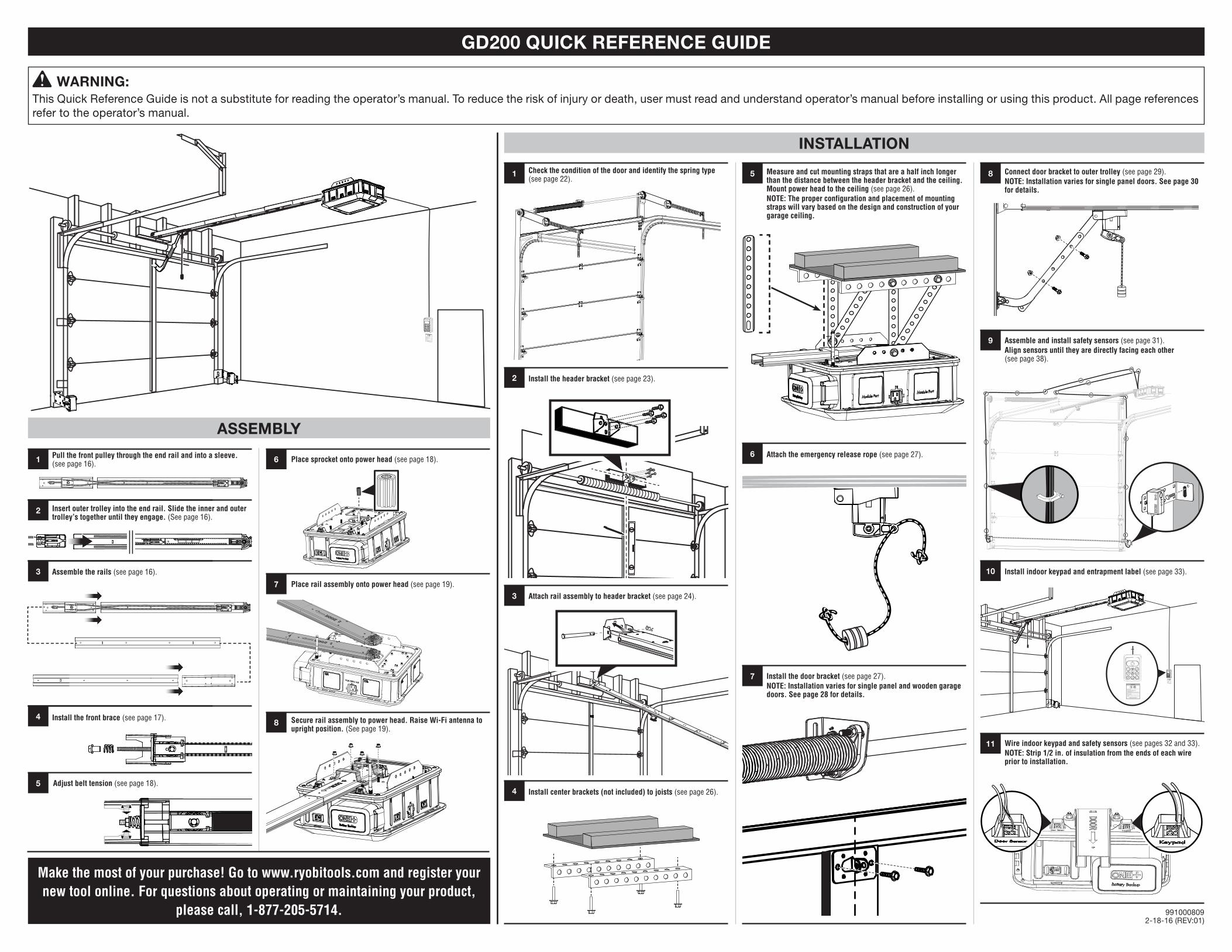
WARNING:This Quick Reference Guide is not a substitute for reading the operator’s manual. To reduce the risk of injury or death, user must read and understand operator’s manual before installing or using this product. All page references refer to the operator’s manual.
ASSEMBLY
INSTALLATION
GD200 QUICK REFERENCE GUIDE
Make the most of your purchase! Go to www.ryobitools.com and register your new tool online. For questions about operating or maintaining your product,
please call, 1-877-205-5714.
Insert outer trolley into the end rail. Slide the inner and outer trolley’s together until they engage. (See page 16).
Assemble the rails (see page 16).
Pull the front pulley through the end rail and into a sleeve. (see page 16).
Install the front brace (see page 17).
2
3
4
Place sprocket onto power head (see page 18).
Adjust belt tension (see page 18).
Place rail assembly onto power head (see page 19).
Secure rail assembly to power head. Raise Wi-Fi antenna to upright position. (See page 19).
Check the condition of the door and identify the spring type (see page 22).
Measure and cut mounting straps that are a half inch longer than the distance between the header bracket and the ceiling. Mount power head to the ceiling (see page 26). NOTE: The proper configuration and placement of mounting straps will vary based on the design and construction of your garage ceiling.
Install indoor keypad and entrapment label (see page 33).
Attach the emergency release rope (see page 27).
Install the header bracket (see page 23).
Install the door bracket (see page 27).NOTE: Installation varies for single panel and wooden garage doors. See page 28 for details.
Wire indoor keypad and safety sensors (see pages 32 and 33).NOTE: Strip 1/2 in. of insulation from the ends of each wire prior to installation.
Attach rail assembly to header bracket (see page 24).
Install center brackets (not included) to joists (see page 26).
1 6
5
7
8
1 5 8
9
10
11
6
2
7
3
4
Child can become trapped or pinned under an automatic garage door resulting in serious injury or death.• Do not allow children to walk or run under a closing door.• Do not allow children to operate door opener controls.• Always keep a closing door within sight.• In the event a person is trapped under the door, push the control button or use the emergency release.• This operator system is equipped with an unattended operation feature. The door could move unexpectedly. Not intended for use with single panel garage doors.Test door opener monthly:• Refer to Operator’s Manual.• Use a 1 ½ inch thick object (or 2 X 4 laid flat) placed on the floor under the closing door.• In the event the door does reverse upon contact, adjust, repair, or replace the opener.
Do not remove or paint over this label. Mount this label next to the wall control.Mount the wall control out of the reach of children at least 5 feet above the floor.
Child can become trapped or pinned under an automatic garage door resulting in serious injury or death.• Do not allow children to walk or run under a closing door.• Do not allow children to operate door opener controls.• Always keep a closing door within sight.• In the event a person is trapped under the door, push the control button or use the emergency release.• This operator system is equipped with an unattended operation feature. The door could move unexpectedly. Not intended for use with single panel garage doors.Test door opener monthly:• Refer to Operator’s Manual.• Use a 1 ½ inch thick object (or 2 X 4 laid flat) placed on the floor under the closing door.• In the event the door does reverse upon contact, adjust, repair, or replace the opener.
Do not remove or paint over this label. Mount this label next to the wall control.
Mount the wall control out of the reach of children at least 5 feet above the floor.
Connect door bracket to outer trolley (see page 29).NOTE: Installation varies for single panel doors. See page 30 for details.
Assemble and install safety sensors (see page 31).Align sensors until they are directly facing each other (see page 38).


![CCNP BCMSN Quick Reference Sheets - Lagout Quick Reference... · CCNP BCMSN Quick Reference Sheets Exam 642-812 ... [ 4 ] CCNP BCMSN Quick Reference Sheets. ... switch would be used](https://static.fdocuments.net/doc/165x107/5a7a6ec87f8b9a05538dccf5/ccnp-bcmsn-quick-reference-sheets-lagout-quick-referenceccnp-bcmsn-quick-reference.jpg)