GD1 MRR guidance for installations 120716final clean - · PDF fileEUROPEAN COMMISSION...
84
EUROPEAN COMMISSION DIRECTORATE-GENERAL CLIMATE ACTION Directorate A – International and Climate Strategy CLIMA.A.3 - Monitoring, Reporting, Verification 1 Guidance Document The Monitoring and Reporting Regulation – General guidance for installations MRR Guidance document No. 1, Version of 16 July 2012 This document is part of a series of documents provided by the Commission services for supporting the implementation of Commission Regulation (EU) No. 601/2012 of 21 June 2012 on the monitoring and reporting of greenhouse gas emissions pursuant to Directive 2003/87/EC of the European Parliament and of the Council 1 . The guidance represents the views of the Commission services at the time of publication. It is not legally binding. This guidance document takes into account the discussions within meetings of the informal Technical Working Group on the Monitoring and Reporting Regula- tion under the WGIII of the Climate Change Committee (CCC), as well as writ- ten comments received from stakeholders and experts from Member States. This guidance document was unanimously endorsed by the representatives of the Member States at the meeting of the Climate Change Committee on 7 June 2012. All guidance documents and templates can be downloaded from the documen- tation section of the Commission’s website at the following address: http://ec.europa.eu/clima/policies/ets/monitoring/index_en.htm. 1 http://eur-lex.europa.eu/LexUriServ/LexUriServ.do?uri=OJ:L:2012:181:0030:0104:EN:PDF
Transcript of GD1 MRR guidance for installations 120716final clean - · PDF fileEUROPEAN COMMISSION...

EUROPEAN COMMISSION DIRECTORATE-GENERAL CLIMATE ACTION Directorate A – International and Climate Strategy
CLIMA.A.3 - Monitoring, Reporting, Verification
1
Guidance Document
The Monitoring and Reporting Regulation –
General guidance for installations
MRR Guidance document No. 1, Version of 16 July 2012
This document is part of a series of documents provided by the Commission
services for supporting the implementation of Commission Regulation (EU) No.
601/2012 of 21 June 2012 on the monitoring and reporting of greenhouse gas
emissions pursuant to Directive 2003/87/EC of the European Parliament and of
the Council1.
The guidance represents the views of the Commission services at the time of
publication. It is not legally binding.
This guidance document takes into account the discussions within meetings of
the informal Technical Working Group on the Monitoring and Reporting Regula-
tion under the WGIII of the Climate Change Committee (CCC), as well as writ-
ten comments received from stakeholders and experts from Member States.
This guidance document was unanimously endorsed by the representatives of
the Member States at the meeting of the Climate Change Committee on 7 June
2012.
All guidance documents and templates can be downloaded from the documen-
tation section of the Commission’s website at the following address:
http://ec.europa.eu/clima/policies/ets/monitoring/index_en.htm.
1 http://eur-lex.europa.eu/LexUriServ/LexUriServ.do?uri=OJ:L:2012:181:0030:0104:EN:PDF
2
TABLE OF CONTENTS
1 SUMMARY ..................................................................................... 4
1.1 Where should I start reading? .................................................................. 4
1.2 What is new in the MRR? .......................................................................... 5
2 INTRODUCTION ............................................................................ 7
2.1 About this document ................................................................................. 7
2.2 How to use this document ........................................................................ 7
2.3 Where to find further information ............................................................. 8
3 THE EU ETS COMPLIANCE CYCLE ........................................... 10
3.1 Importance of MRV in the EU ETS .......................................................... 10
3.2 Overview of the compliance cycle.......................................................... 11
3.3 The importance of the monitoring plan ................................................. 13
3.4 Milestones and deadlines ........................................................................ 14
3.4.1 The annual compliance cycle ..................................................................... 14
3.4.2 Preparing for the third trading period ......................................................... 16
3.5 Roles and responsibilities ....................................................................... 18
4 CONCEPTS AND APPROACHES ............................................... 19
4.1 Underlying principles .............................................................................. 19
4.2 Source streams, emission sources and related terms......................... 21
4.3 Monitoring approaches ........................................................................... 22
4.3.1 Standard methodology ............................................................................... 23
4.3.2 Mass balance approach ............................................................................. 25
4.3.3 Measurement based approaches ............................................................... 27
4.3.4 Fall-back methodology ............................................................................... 29
4.3.5 Combinations of approaches ..................................................................... 30
4.4 Categorisation of installations, emission sources and source streams ...................................................................................................... 30
4.4.1 Installation categories ................................................................................ 31
4.4.2 Installations with low emissions ................................................................. 32
4.4.3 Source streams .......................................................................................... 32
4.4.4 Emission sources ....................................................................................... 34
4.5 The tier system ......................................................................................... 34
4.6 Reasons for derogation ........................................................................... 35
4.6.1 Unreasonable costs ................................................................................... 36
4.7 Uncertainty ................................................................................................ 38
5 THE MONITORING PLAN ............................................................ 40
5.1 Developing a monitoring plan ................................................................. 40
5.2 Selecting the correct tier ......................................................................... 43
3
5.3 Uncertainty assessment as supporting document............................... 46
5.3.1 General requirements ................................................................................ 46
5.3.2 Simplifications ............................................................................................ 47
5.3.3 Further guidance ........................................................................................ 48
5.4 Procedures and the monitoring plan ..................................................... 48
5.5 Data flow and control system ................................................................. 53
5.6 Keeping the monitoring plan up to date ................................................ 54
5.6.1 Significant changes .................................................................................... 55
5.6.2 Non-significant updates of the monitoring plan .......................................... 56
5.7 The improvement principle ..................................................................... 57
6 CALCULATION BASED APPROACHES .................................... 59
6.1 Monitoring of activity data ...................................................................... 59
6.1.1 Tier definitions ............................................................................................ 59
6.1.2 Relevant elements of the monitoring plan .................................................. 60
6.2 Calculation factors – Principles.............................................................. 63
6.2.1 Default values............................................................................................. 64
6.2.2 Laboratory analyses ................................................................................... 67
6.3 Calculation factors – specific requirements ......................................... 68
6.3.1 Emission factor ........................................................................................... 68
6.3.2 Net calorific value (NCV) ............................................................................ 69
6.3.3 Oxidation factor and conversion factors ..................................................... 70
6.3.4 Carbon content in case of mass balances ................................................. 70
6.3.5 Biomass fraction ......................................................................................... 71
6.4 PFC emissions.......................................................................................... 71
7 SIMPLIFIED APPROACHES ....................................................... 73
7.1 Installations with low emissions ............................................................ 73
7.2 Other “simple” installations .................................................................... 73
7.2.1 Practical approach to simplifications .......................................................... 74
7.2.2 Determining the scope for simplified approaches ...................................... 75
8 CEMS ........................................................................................... 78
8.1 General requirements .............................................................................. 78
8.2 N2O emissions .......................................................................................... 80
8.3 Transferred / inherent CO2 and CCS ...................................................... 80
8.3.1 Transferred CO2 and CCS ......................................................................... 80
8.3.2 Inherent CO2 .............................................................................................. 81
9 ANNEX ......................................................................................... 83
9.1 Acronyms .................................................................................................. 83
9.2 Legislative texts ....................................................................................... 83

4
1 SUMMARY
Monitoring and reporting of emissions is a cornerstone of the EU ETS2 (the Un-
ion Emissions Trading Scheme). Following the revision of the EU ETS Directive
in 2009, updated rules for monitoring and reporting have been laid down in an
EU Regulation (the Monitoring and Reporting Regulation, hereinafter the
“MRR”). Together with a new Regulation for verification of emissions and ac-
creditation of verifiers (the “AVR”), the MRR replaces the Monitoring and Re-
porting Guidelines (MRG 2007). The MRR is applicable from the third trading
period onwards (that is for emissions from 1 January 2013).
This guidance document is the first of a series of guidance documents and elec-
tronic templates provided by the Commission services to support the EU-wide
harmonised implementation of the MRR. It gives an introduction to the EU ETS
compliance system, the concepts used for monitoring and reporting of station-
ary installations, and then describes in more detail the requirements laid down
in the MRR for the possible monitoring approaches. This guidance does not add
to the mandatory requirements of the MRR, but it is aimed at assisting in more
correct interpretation and facilitated implementation.
This guidance document represents the views of the Commission services at
the time of publication. It is not legally binding.
Note that this document does not cover requirements for aircraft operators. Air-
craft operators in search of guidance on monitoring and reporting in the EU ETS
are invited to consult guidance document No. 2.
1.1 Where should I start reading?
This document has been developed to guide readers who are new to the EU
ETS as well as those who are already familiar with the EU ETS. The later group
should in particular pay attention to sections which are marked with a “NEW”
sign throughout the document (for a list of guiding symbols see section 2.2).
Section 1.2 of this summary will serve as useful starting point.
Readers with little experience of the EU ETS and its MRV (Monitoring, Report-
ing and Verification) system should read in particular chapter 3 (about the EU
ETS compliance cycle) and chapter 4 (concepts and approaches). All readers
who need to monitor an installation and therefore have to develop (or update) a
monitoring plan, are advised to check chapter 5 on monitoring plans. Depending
on the monitoring approaches relevant for the installation to be monitored,
chapters 6 (calculation-based approaches) and 8 (measurement-based ap-
proaches) will give valuable insight into the details of MRR requirements for
those approaches.
The MRR has put considerable emphasis on simplifying monitoring wherever
this is possible for cost effectiveness reasons without compromising the robust-
2 For an explanation of acronyms and for references of legislative texts please see the annex of this document.
5
ness of the monitoring. Operators in search for such options are advised to look
out for the “simplified!” icon.
Operators of installations with low emissions (for definition see section 4.4.2)
should look for the “small” icon, and in particular to section 7.1. Finally, the MRR
has provided a new option for Member States to provide for standardised and
simplified monitoring plan templates. This option is discussed in detail in section
7.2 of this document.
1.2 What is new in the MRR?
The M&R Regulation has been developed with view to enhancing EU-wide
harmonisation of approaches beyond that already achieved by Member State
implementation of MRG 2007. It also takes into account several best practices
found in the Member States. Therefore, a reader may sometimes be already
familiar with the approach presented here, whereas the same approach will be
new to a reader from another Member State. Readers who want to focus in par-
ticular on new elements of the MRR when reading this guidance, should espe-
cially note the following changes compared to the MRG 2007:
� The central role of the monitoring plan (MP) for the whole MRV system has
been further emphasised. For development of a new monitoring plan or for
revision of an existing MP, see section 5.1.
� The requirements for choosing the appropriate and required tier (the tier
hierarchy) have been amended (see section 5.2), as well as the definitions
for the source stream categories (major, minor and de-minimis source
streams, see section 4.4).
� Important clarifications have been introduced regarding the role of written
procedures, which supplement the MP with various details, but which are
kept separate from the MP in order to facilitate their more frequent mainte-
nance and implementation. This is described in section 5.4.
� The MRR has also introduced new rules for the process of updating the
monitoring plan, as discussed in section 5.6. Furthermore the principle of
continuous improvement of the MP has been strengthened by the MRR,
including a requirement to react to recommendations of the verifier (see
section 5.7).
� Further requirements in the context of the monitoring plan concern the evi-
dence for meeting the specific tiers, including an uncertainty assessment
as appropriate (see section 5.3), and the risk assessment necessary to es-
tablish an appropriate control system concerning the data flows of the in-
stallation (see section 5.5). These “supporting documents” must be submit-
ted to the competent authority together with the monitoring plan3.
� Some terminology has changed (“calculation factors” as an overarching
term for emission factor, net calorific value, oxidation factor, conversion
factor, biomass fraction, carbon content; and introduction of the “prelimi-
nary emission factor). For further details see section 4.3.
3 Installations with low emissions (see section 4.4.2) are exempt from this requirement.
small
6
� Improved possibilities to combine the various allowed monitoring ap-
proaches, i.e. calculation-based approaches (standard and mass-balance
methods), measurement-based approaches and the “fall-back” approach
(i.e. no-tier methodology). In particular, measurement-based approaches
have been put on equal footing with calculation-based approaches includ-
ing in relation to minimum tier requirements (see section 4.3.5).
� When selecting a particular monitoring approach, and when deciding upon
possible improvements thereof, the concept of avoiding unreasonable
costs is crucial. The MRR has added clarification concerning interpretation
of unreasonable costs (see section 4.6.1).
� When assessing the appropriateness of a measuring instrument for the de-
termination of quantities of fuels and materials, the uncertainty of the
measurement is the main parameter to check, and the MRR has intro-
duced flexibility to allow several new approaches, including reliance on na-
tional legal metrological control where appropriate and possible (see sec-
tion 5.3). The MRR has furthermore strengthened measures for securing
regular maintenance, calibration and adjustment of metering equipment.
� The MRR uses the same definition for biomass, biofuels and bioliquids as
the Directive on Renewable Energy Sources (RES-D). Consequently, the
sustainability criteria established by the RES-D must be applied where rel-
evant in order to apply an emission factor of zero to such biomass. Note
that this topic is covered in detail in a separate guidance document (see
section 2.3 for where to find other guidance documents).
� For cases where calculation factors are to be determined using laboratory
analyses, the MRR contains two major new elements: The requirement to
have a dedicated sampling plan (in the form of a written procedure) ap-
proved by the competent authority, and clarifications for criteria by which a
laboratory can be regarded as equivalent to an EN ISO/IEC 17025 accred-
ited laboratory (see section 6.2.2).
� Rules for transferred and inherent CO2 have been updated (see section
8.3).
� The interplay with the verification, as regulated by the new A&V Regula-
tion, has been significantly improved. In particular, the rules for the data
flow and control activities of operators have been elaborated, as shown in
section 5.5, and the improvement principle establishes a feedback loop
from the verifier’s findings to the operator’s monitoring plan (see section
5.7).
� Finally, the MRR sends a strong signal for harmonisation, as it has laid a
basis for the Commission to provide electronic templates4 for monitoring
plans, emission reports and other communication between operators, veri-
fiers and competent authorities. Those templates are published together
with this series of guidance documents (see section 2.3 for where to find
other guidance documents).
4 Note that Member States may provide their own templates or use more advanced electronic re-porting systems (e.g. web-based systems), if they require at least the same data.
7
2 INTRODUCTION
2.1 About this document
This document has been written to support the M&R Regulation, by explaining
its requirements in a non-legislative language. For some more specific technical
issues, further guidance documents will be made available. The set of guidance
documents is further complemented by electronic templates5 for information to
be submitted by operators to the competent authority. However, it should al-
ways be remembered that the Regulation is the primary requirement.
This document interprets the Regulation regarding requirements for installa-
tions. It also builds on guidance and best practice developed during the first two
phases6 of the EU ETS (2005 to 2007 and 2008 to 2012), in particular the expe-
rience gathered by the Member States based on the Monitoring and Reporting
Guidelines (MRG 2007) including a set of guidance notes known as the ETSG7
guidance notes developed under the framework of IMPEL. It also takes into ac-
count the valuable input from the task force on monitoring established under the
EU ETS Compliance Forum, and from the informal technical working group
(TWG) of Member State experts established under Working Group 3 of the Cli-
mate Change Committee.
2.2 How to use this document
Where article numbers are given in this document without further specification,
they always refer to the M&R Regulation. For acronyms, references to legisla-
tive texts and links to further important documents, please see the Annex.
This document only refers to emissions starting from 2013. Although most of the
concepts have been used in the MRG 2007 before, this document does not give
a detailed comparison to the MRG 2007. Instead, a symbol (such as on the
margin here) indicates where changes to requirements compared to the MRG
have taken place, or where concepts have not been used in the MRG before.
This symbol points to important hints for operators and competent authorities.
This indicator is used where significant simplifications to the general require-
ments of the MRR are promoted.
The light bulb symbol is used where best practices are presented.
The small installation symbol is used to guide the reader to topics which are ap-
plicable for installations with low emissions.
5 Note that Member States may define their own templates, which must contain at least the same information as the Commission’s templates.
6 Within this documents, as in some Member States, the term 'phase' is used with the same mean-ing as 'trading period' (Article 3(2) of the MRR).
7 ETS support group; IMPEL is the European Union Network for the Implementation and Enforce-ment of Environmental Law. The notes are found at http://impel.eu/projects/emission-trading-proposals-for-future-development-of-the-eu-ets-phase-ii-beyond.
small
8
The tools symbol tells the reader that other documents, templates or electronic
tools are available from other sources (including those still under development).
The book symbol points to examples given for the topics discussed in the sur-
rounding text.
2.3 Where to find further information
All guidance documents and templates provided by the Commission on the ba-
sis of the M&R Regulation and the A&V Regulation can be downloaded from the
Commission’s website at the following address:
http://ec.europa.eu/clima/policies/ets/monitoring/index_en.htm
The following documents are provided8:
� Guidance document No. 1 (this document): “The Monitoring and Re-
porting Regulation – General guidance for installations”.
� Guidance document No. 2: “The Monitoring and Reporting Regulation –
General guidance for aircraft operators”. This document outlines the
principles and monitoring approaches of the MRR relevant for the avia-
tion sector. It also includes guidance on the monitoring plan templates
provided by the Commission.
� Guidance document No. 3: “Biomass issues in the EU ETS”: This doc-
ument discusses the application of sustainability criteria for biomass, as
well as the requirements of Articles 38, 39 and 53 of the MRR. This
document is relevant for operators of installations as well as for aircraft
operators.
� Guidance document No. 4: “Guidance on Uncertainty Assessment”.
This document for installations gives information on assessing the un-
certainty associated with the measurement equipment used, and thus
helps the operator to determine whether he can comply with specific tier
requirements.
� Guidance document No. 5: “Guidance on sampling and analysis” (only
for installations). This document deals with the criteria for the use of
non-accredited laboratories, development of a sampling plan, and vari-
ous other related issues concerning the monitoring of emissions in the
EU ETS.
� Guidance document No. 6: “Data flow activities and control system”.
This document discusses possibilities to describe data flow activities for
monitoring in the EU ETS, the risk assessment as part of the control
system, and examples of control activities.
8 This list is at the current stage non-exhaustive. Further documents may be added later.

9
The Commission furthermore provides the following electronic templates9:
� Template No. 1: Monitoring plan for the emissions of stationary installations
� Template No. 2: Monitoring plan for the emissions of aircraft operators
� Template No. 3: Monitoring plan for the tonne-kilometre data of aircraft op-
erators
� Template No. 4: Annual emissions report of stationary installations
� Template No. 5: Annual emissions report of aircraft operators
� Template No. 6: Tonne-kilometre data report of aircraft operators
Besides these documents dedicated to the MRR, a separate set of guidance
documents on the A&V Regulation is available under the same address. Fur-
thermore, the Commission has provided guidance on the scope of the EU ETS
which should be consulted to decide whether an installation or part thereof
should be included in the EU ETS. That guidance is available under
http://ec.europa.eu/clima/policies/ets/docs/guidance_interpretation_en.pdf
Although not directly related to monitoring issues, with the exception of report-
ing on relevant changes in the installation under Article 24 of the Community-
wide Implementation Measures, the set of guidance documents and templates
provided by the Commission on the allocation process for the third phase are
also acknowledged at this point. That set of guidance can be found under
http://ec.europa.eu/clima/policies/ets/benchmarking/documentation_en.htm
All EU legislation is found on EUR-Lex: http://eur-lex.europa.eu/
The most important legislation is furthermore listed in the Annex of this docu-
ment.
Also competent authorities in the Member States may provide useful guidance
on their own websites. Operators of installations should in particular check if the
competent authority provides workshops, FAQs, helpdesks etc.
9 This list is at the current stage non-exhaustive. Further templates may be added later.

10
3 THE EU ETS COMPLIANCE CYCLE
3.1 Importance of MRV in the EU ETS
Monitoring, reporting and verification (MRV) of emissions play a key role in the
credibility of any emission trading system. Without MRV, compliance would lack
transparency and be much more difficult to track, and enforcement compro-
mised. This holds true also for the European Union Emission Trading Scheme
(EU ETS). It is the complete, consistent, accurate and transparent monitoring,
reporting and verification system that creates trust in emissions trading. Only in
this way can it be ensured that operators meet their obligation to surrender suf-
ficient allowances.
This observation is based on the twofold nature of the EU ETS: On the one
hand it is a market based instrument. It has allowed a significant market to
evolve, in which market participants want to know the monetary value of the al-
lowances they get allocated, they trade and they have to surrender. On the oth-
er hand it is an instrument for achieving an environmental benefit. But in con-
trast to other environmental legislation, the goal is not to be achieved by indi-
viduals, but the whole group of EU ETS participants having to achieve the goal
jointly. This requires a considerable level of fairness between participants, en-
sured by a solid MRV system. The competent authorities’ oversight activities
contribute significantly to ensuring that the goal set by the cap is reached,
meaning that the anticipated emission reductions are delivered in practice. It is
therefore the responsibility of the competent authorities together with the ac-
creditation bodies to protect the integrity of the EU ETS by supervising the well-
functioning of the MRV system.
Both, carbon market participants and competent authorities want to have assur-
ance that one tonne CO2 equivalent emitted finds its equivalent of one tonne
reported (for the purpose of one allowance to be surrendered). This principle
has become known already from the early days of the EU ETS as the proverbial
postulation: “A tonne must be a tonne!”
In order to ensure that this is achieved in a robust, transparent, verifiable and
yet cost effective way, the EU ETS Directive10
provides a solid basis for a good
monitoring, reporting and verification system. This is achieved by Articles 14
and 15 in connection with Annexes IV and V of the EU ETS Directive. Based on
Article 14, the Commission has provided the “M&R Regulation11
” (MRR), which
replaces the well-known Monitoring and Reporting Guidelines (MRG 2007) for
emissions starting from 1 January 2013.
However, it has always been recognised by the Commission as well as by
Member States that a complex and technical legislation such as the MRR needs
to be supported by further guidance, in order to ensure harmonised implemen-
10
Directive 2003/87/EC of the European Parliament and of the Council of 13 October 2003 estab-lishing a scheme for greenhouse gas emission allowance trading within the Community and amending Council Directive 96/61/EC; most recently amended by Directive 2009/29/EC, making it the so-called “revised EU ETS Directive”.
11 Commission Regulation (EU) No. 601/2012 of 21 June 2012 on the monitoring and reporting of greenhouse gas emissions pursuant to Directive 2003/87/EC of the European Parliament and of the Council. Download: http://eur-lex.europa.eu/LexUriServ/LexUriServ.do?uri=OJ:L:2012:181:0030:0104:EN:PDF

11
tation throughout all Member States, and for paving the way to smooth compli-
ance through pragmatic approaches wherever possible.
Furthermore a Regulation for verification and accreditation of verifiers has been
provided (the “A&V Regulation”12
), for which a separate series of guidance doc-
uments is being developed by the Commission.
3.2 Overview of the compliance cycle
The annual process of monitoring, reporting, verification of emissions and the
competent authority’s procedure for accepting emission reports are often re-
ferred to as the “compliance cycle”. Figure 1 shows the main elements of this
cycle.
On the right side of the picture there is the “main cycle”: The operator monitors
the emissions throughout the year. After the end of the calendar year (within
three months) he must prepare the annual emissions report (AER), seek verifi-
cation and submit the verified report to the competent authority (CA). The latter
must correlate with the surrender of allowances in the Registry system13
. Here
the principle “a tonne must be a tonne” translates into “a tonne must be an al-
lowance”, i.e. at this point the market value of the allowance is correlated with
the costs of meeting the environmental goal of the EU ETS. Thereafter the mon-
itoring goes on, as shown in the picture. More precisely, the monitoring contin-
ues without any stop at the end of the year.
The monitoring process needs a firm basis. Resulting data must be sufficiently
robust for creating trust in the reliability of the ETS, including the fairness of the
surrender obligation, and it must be consistent throughout the years. Therefore
the operator must ensure that the monitoring methodology is documented in
writing, and cannot be changed arbitrarily. In the case of the EU ETS, this writ-
ten methodology is called the Monitoring Plan (MP) of the installation (see Fig-
ure 1). It is part of the permit14
, which every installation in the EU ETS must
have for the emission of greenhouse gases.
The figure also shows that the monitoring plan, although very specific for an in-
dividual installation, must follow the requirements of the EU-wide applicable leg-
islation, in particular the Monitoring and Reporting Regulation. As a result, the
MRV system of the EU ETS is able to square the circle between strict EU-wide
rules providing reliability and preventing arbitrary and undue simplifications, and
allowing for sufficient flexibility for the circumstances of individual installations.
12
Commission Regulation (EU) No 600/2012 of 21 June 2012 on the verification of greenhouse gas emission reports and tonne-kilometre reports and the accreditation of verifiers pursuant to Di-rective 2003/87/EC of the European Parliament and of the Council. Download: http://eur-lex.europa.eu/LexUriServ/LexUriServ.do?uri=OJ:L:2012:181:0001:0029:EN:PDF
13 For the purpose of simplification, the surrender of allowances has not been included in the picture. Similarly, the picture also ignores the processes of allocation and trading of allowances.
14 This permit pursuant to Article 4 of the EU ETS Directive is usually referred to as the GHG emis-sion permit. Note that for simplifying administration, according to point (c) of Article 6(2), the moni-toring plan may be treated separately from the permit when it comes to formal changes of the monitoring plan.

12
Monitoring throughout the year
Verification
Annual Report
Submit report
Legislation (MRR)
Monitoring plan (installation specific)
Improvement
suggestions
Competent Authority Compliance
checks
Picture by
Figure 1: Principle of the EU ETS compliance cycle
Figure 1 also shows some key responsibilities of the competent authority. It has
to supervise the compliance of the operators. As the first step, the CA has to
approve every monitoring plan before it is applied. This means that the monitor-
ing plans developed by the operator are checked for compliance with the MRR’s
requirements. Where the operator makes use of some simplified approaches al-
lowed by the MRR, this must be justified by the operator, for example, based on
the grounds of technical feasibility or unreasonable costs, where otherwise re-
quired higher tiers cannot be achieved.
Secondly, the CA may carry out inspections at installations, to gather assurance
that the monitoring plan is well aligned to the reality of the installation. The CA
may, for example, check if the installed meters are of the type laid down in the
monitoring plan, whether required data is retained, and written procedures are
followed as required.
Finally, it is the responsibility of the competent authority to carry out checks on
the annual emission reports. This includes spot checks on the already verified
reports, but also cross-checks with figures entered in the verified emissions ta-
ble of the registry system, and checking that sufficient allowances have been
surrendered.
However, the compliance cycle has a wider perspective. As Figure 1 shows,
there is a second cycle. This is the regular review of the monitoring plan, for
which the verification report may provide valuable input. Besides, the operator is
required to continuously strive for further improving the monitoring methodology.
Any inspections by the CA should also inter alia aim at identifying elements of
the monitoring methodology which are not appropriate any more, for example,
after technical changes have been made to the installation.

13
3.3 The importance of the monitoring plan
From the previous section it becomes apparent, that the approved monitoring
plan is the most important document for every installation participating in the EU
ETS. Like a recipe for a cook and like the management handbook for a certified
quality management system, it serves as manual for the operator’s tasks.
Therefore it should be written in a way that allows all, particularly new staff to
immediately follow the instructions. It must also allow the CA to understand
quickly the operator’s monitoring activities. Finally, the MP is the guide for the
verifier against which the operator’s emission report is to be judged.
Typical elements of a monitoring plan include the following activities of the op-
erator (applicability depends on the specific installation’s circumstances):
� Data collection (metering data, invoices, production protocols,...);
� Sampling of materials and fuels;
� Laboratory analyses of fuels and materials;
� Maintenance and calibration of meters;
� Description of calculations and formulae to be used;
� Control activities (e.g. four eyes principle for data collection);
� Data archiving (including protection against manipulation);
� Regular identification of improvement possibilities.
However, monitoring plans must be drafted carefully (� chapter 5), so that ad-
ministrative burden is minimised. Since the MP is to be approved by the compe-
tent authority, it goes without saying that also changes of the MP are only al-
lowed with the consent of the CA. The M&R Regulation reduces the administra-
tive efforts here by allowing two approaches which should already be taken into
account when drafting monitoring plans:
� Only changes which are “significant” need the approval by the CA (Article
15 of the MRR, see section 5.6 below);
� Monitoring activities which are not crucial in every detail, and which by their
nature tend to be frequently amended as found necessary, may be put into
“written procedures”, which are mentioned and described briefly in the MP,
but the detail of which are not considered part of the approved MP. The re-
lationship between monitoring plan and written procedures is described in
more detail in section 5.4.
Because of the importance of the monitoring plan, the Commission is also
providing templates for monitoring plans. Some Member States might have pro-
vided customized templates based on the Commission’s templates, other Mem-
ber States use a dedicated (usually web-based) electronic reporting system
(that must also meet at least stated Commission requirements). Before develop-
ing a monitoring plan, operators are therefore advised to check their competent
authority’s website or make direct contact with the CA for finding out the con-
crete requirements for submitting a monitoring plan. National legislation may al-
so state specific requirements.
14
3.4 Milestones and deadlines
3.4.1 The annual compliance cycle
The EU ETS compliance cycle is built around the requirement that monitoring is
always related to the calendar year15
, as shown in Table 1 and Figure 2. Opera-
tors have three months after the end of the year to finalise the emission reports
and to get them verified by an accredited verifier in accordance with the A&V
Regulation. Thereafter operators have to surrender the corresponding amount
of allowances. Subject to national legislation, the competent authority may or
shall perform (spot) checks on the reports received, and must determine a con-
servative estimate of the emissions, if the operator fails to submit an emissions
report, or where a report has been submitted, but it is either not compliant with
the MRR or not (positively) verified in accordance with the A&V Regulation (Ar-
ticle 70(1) of the MRR). When the CA detects any kind of errors in the submitted
reports, corrections to the verified emissions figure may be a result. Note that
for such corrections no deadline is given by EU legislation. However, there may
be some requirement given in national legislation.
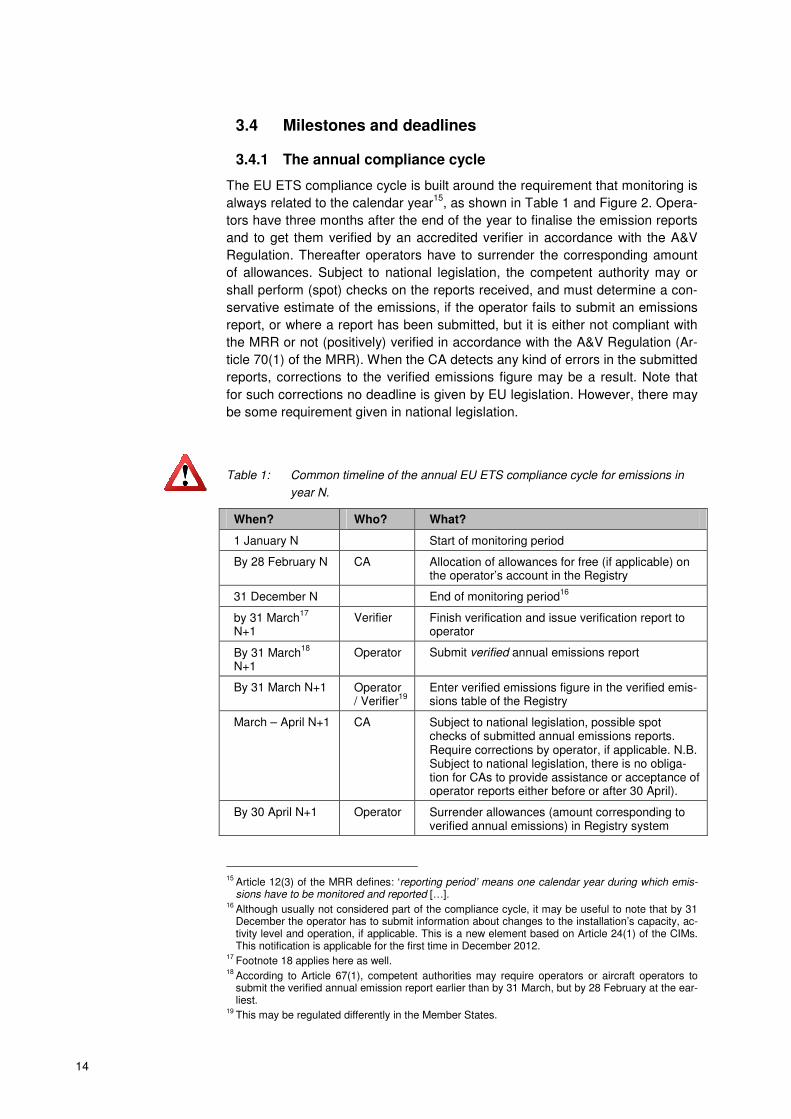
Table 1: Common timeline of the annual EU ETS compliance cycle for emissions in
year N.
When? Who? What?
1 January N Start of monitoring period
By 28 February N CA Allocation of allowances for free (if applicable) on the operator’s account in the Registry
31 December N End of monitoring period16
by 31 March17
N+1
Verifier Finish verification and issue verification report to operator
By 31 March18
N+1
Operator Submit verified annual emissions report
By 31 March N+1 Operator / Verifier
19
Enter verified emissions figure in the verified emis-sions table of the Registry
March – April N+1 CA Subject to national legislation, possible spot checks of submitted annual emissions reports. Require corrections by operator, if applicable. N.B. Subject to national legislation, there is no obliga-tion for CAs to provide assistance or acceptance of operator reports either before or after 30 April).
By 30 April N+1 Operator Surrender allowances (amount corresponding to verified annual emissions) in Registry system
15
Article 12(3) of the MRR defines: ‘reporting period’ means one calendar year during which emis-sions have to be monitored and reported […].
16 Although usually not considered part of the compliance cycle, it may be useful to note that by 31 December the operator has to submit information about changes to the installation’s capacity, ac-tivity level and operation, if applicable. This is a new element based on Article 24(1) of the CIMs. This notification is applicable for the first time in December 2012.
17 Footnote 18 applies here as well.
18 According to Article 67(1), competent authorities may require operators or aircraft operators to submit the verified annual emission report earlier than by 31 March, but by 28 February at the ear-liest.
19 This may be regulated differently in the Member States.
15
When? Who? What?
By 30 June N+1 Operator Submit report on possible improvements of the MP, if applicable
20
(No specified deadline)
CA Carry out further checks on submitted annual emissions reports, where considered necessary or as may be required by national legislation; require changes of the emissions data and surrender of additional allowances, if applicable (in accordance with Member State legislation).
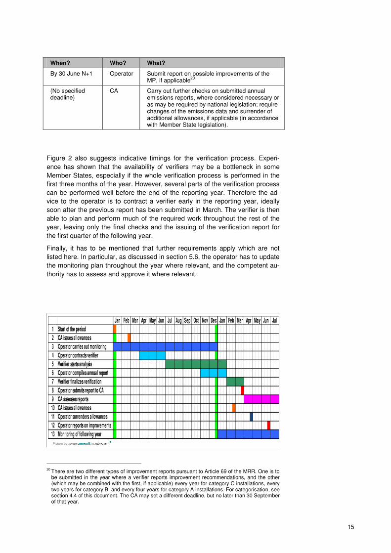
Figure 2 also suggests indicative timings for the verification process. Experi-
ence has shown that the availability of verifiers may be a bottleneck in some
Member States, especially if the whole verification process is performed in the
first three months of the year. However, several parts of the verification process
can be performed well before the end of the reporting year. Therefore the ad-
vice to the operator is to contract a verifier early in the reporting year, ideally
soon after the previous report has been submitted in March. The verifier is then
able to plan and perform much of the required work throughout the rest of the
year, leaving only the final checks and the issuing of the verification report for
the first quarter of the following year.
Finally, it has to be mentioned that further requirements apply which are not
listed here. In particular, as discussed in section 5.6, the operator has to update
the monitoring plan throughout the year where relevant, and the competent au-
thority has to assess and approve it where relevant.
Picture by
1 Start of the period
2 CA issues allowances
3 Operator carries out monitoring
4 Operator contracts verifier
5 Verifier starts analysis
6 Operator compiles annual report
7 Verifier finalizes verification
8 Operator submits report to CA
9 CA assesses reports
10 CA issues allowances
11 Operator surrenders allowances
12 Operator reports on improvements
13 Monitoring of following year
Sep Oct MayJan Feb Mar AprNov DecJul Aug Jun JulJan Feb Mar Apr May Jun
20
There are two different types of improvement reports pursuant to Article 69 of the MRR. One is to be submitted in the year where a verifier reports improvement recommendations, and the other (which may be combined with the first, if applicable) every year for category C installations, every two years for category B, and every four years for category A installations. For categorisation, see section 4.4 of this document. The CA may set a different deadline, but no later than 30 September of that year.

16
Figure 2: Example timeline for the EU ETS compliance cycle. Please see Table 1
for explanation of deadlines. Note in particular that subject to national
legislation, the timeline may differ.
3.4.2 Preparing for the third trading period
In order to make the compliance cycle work, the monitoring plans of all installa-
tions need to be approved by the competent authority before the start of the
monitoring period. For new entrants to the ETS, the MP must be approved be-
fore the start of operations. For the start of the third trading phase the transition
from MRG 2007 to the application of the MRR requires that the monitoring plans
of all installations be revised and adapted to the new requirements. Based on
experience from previous ETS phases, such a general revision process may
require several months and should be well prepared. For the purpose of provid-
ing additional guidance, a (legally non-binding) timeline is presented here. Rela-
tively long timescales are assumed, as required for the most complex installa-
tions, as follows: Firstly, preparation of the monitoring plan by the operators can
take up to several months, depending on the complexity of installations. How-
ever, for simple installations, the monitoring plan may be compiled within a few
working days.
Because the CA will also need a few weeks or months for assessing all submit-
ted MPs (depending on current workload) and because operators will then need
some weeks for finally implementing the new approved MP, it can be envisaged
that the CA should start early with workshops and other information for opera-
tors as considered appropriate. This especially concerns 2012 (the year before
the MRR is to be applied). Operators in turn should prepare the new monitoring
plans early enough for submission of MPs by the mid of the year, but at the lat-
est by end of September21
. An example timeline is shown in Table 2.
Table 2: Model timeline for preparing the EU ETS compliance cycle for the start of the
new trading period. Note that deadlines may significantly differ according to
the Member States.
When? Who? What?
May – Sept. 2012 Operator Check existing MP for required updates, or devel-op new MP, as applicable
July – Sept. 2012 CA Suggested deadline for receiving new or updated MP from operators
July – Dec. 2012 CA Check and approve MPs
Oct. – Dec. 2012 Operator Prepare for implementation of approved MP
1 January 2013 Start of monitoring period using the new MRR re-quirements
21
Note that the concrete deadlines set by competent authorities in the Member States may differ from this assumption.

17
18
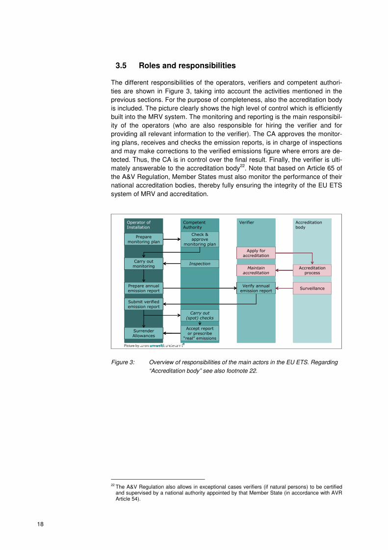
3.5 Roles and responsibilities
The different responsibilities of the operators, verifiers and competent authori-
ties are shown in Figure 3, taking into account the activities mentioned in the
previous sections. For the purpose of completeness, also the accreditation body
is included. The picture clearly shows the high level of control which is efficiently
built into the MRV system. The monitoring and reporting is the main responsibil-
ity of the operators (who are also responsible for hiring the verifier and for
providing all relevant information to the verifier). The CA approves the monitor-
ing plans, receives and checks the emission reports, is in charge of inspections
and may make corrections to the verified emissions figure where errors are de-
tected. Thus, the CA is in control over the final result. Finally, the verifier is ulti-
mately answerable to the accreditation body22
. Note that based on Article 65 of
the A&V Regulation, Member States must also monitor the performance of their
national accreditation bodies, thereby fully ensuring the integrity of the EU ETS
system of MRV and accreditation.
Picture by
Operator of Installation
Prepare
monitoring plan
Carry out monitoring
Prepare annual emission report
Submit verified emission report
Surrender Allowances
Verifier
Verify annual emission report
Apply for accreditation
Maintain accreditation
Competent Authority
Check & approve
monitoring plan
Carry out
(spot) checks
Accept report
or prescribe “real” emissions
Inspection
Accreditation body
Accreditationprocess
Surveillance
Picture byPicture by
Operator of Installation
Prepare
monitoring plan
Carry out monitoring
Prepare annual emission report
Submit verified emission report
Surrender Allowances
Verifier
Verify annual emission report
Apply for accreditation
Maintain accreditation
Competent Authority
Check & approve
monitoring plan
Carry out
(spot) checks
Accept report
or prescribe “real” emissions
Inspection
Accreditation body
Accreditationprocess
Surveillance
Operator of Installation
Prepare
monitoring plan
Carry out monitoring
Prepare annual emission report
Submit verified emission report
Surrender Allowances
Operator of Installation
Prepare
monitoring plan
Carry out monitoring
Prepare annual emission report
Submit verified emission report
Surrender Allowances
Verifier
Verify annual emission report
Apply for accreditation
Maintain accreditation
Verifier
Verify annual emission report
Apply for accreditation
Verifier
Verify annual emission report
Apply for accreditation
Maintain accreditation
Competent Authority
Check & approve
monitoring plan
Carry out
(spot) checks
Accept report
or prescribe “real” emissions
Inspection
Competent Authority
Check & approve
monitoring plan
Carry out
(spot) checks
Accept report
or prescribe “real” emissions
Inspection
Accreditation body
Accreditationprocess
Surveillance
Accreditation body
Accreditationprocess
Surveillance
Figure 3: Overview of responsibilities of the main actors in the EU ETS. Regarding
“Accreditation body” see also footnote 22.
22
The A&V Regulation also allows in exceptional cases verifiers (if natural persons) to be certified and supervised by a national authority appointed by that Member State (in accordance with AVR Article 54).

19
4 CONCEPTS AND APPROACHES
This chapter is dedicated to explaining the most important terms and concepts
needed for developing a monitoring plan.
4.1 Underlying principles
Articles 5 to 9 of the MRR outline the guiding principles which the operators
have to follow when fulfilling their obligations. These are:
1. Completeness (Article 5): The completeness of emission sources and
source streams is at the very core of the EU ETS monitoring principles. In
order to ensure completeness of emissions monitored, the operator should
take into account the following considerations:
� Article 4 of the MRR requires that all process and combustion emis-
sions from all emission sources and source streams (� section 4.2)
are to be included, which belong to activities listed in Annex I of the
EU ETS Directive, or which are included in the EU ETS by “opt-in”
(pursuant to Article 24 of the Directive, as e.g. some N2O emitting ac-
tivities during the second ETS phase).
� Annex I of the EU ETS Directive states that all combustion activities of
an installation are to be included in the EU ETS, if the threshold of any
of the other activities is exceeded. Due to the definition of “combus-
tion” in the Directive23
, this includes process emissions from flue gas
scrubbing in these cases, too.
� Further specific points to be considered for each activity can be found
in Annex IV of the MRR, under the heading “Scope” for each activity.
� Article 20 requires emissions from regular operations as well as from
abnormal events including start-up and shut-down and emergency sit-
uations to be included.
� Emissions from mobile machinery used within the installation are gen-
erally excluded.
� Operators should also be aware of the guidance24
issued by the
Commission regarding the interpretation of Annex I of the EU ETS Di-
rective.
2. Consistency and comparability (Article 6(1)): Time series25
of data need
to be consistent throughout the years. Arbitrary changes of monitoring meth-
odologies are prohibited. This is why the monitoring plan has to be approved
by the competent authority, such as also significant changes to the MP. Be-
cause the same monitoring approaches are defined for all installations, from
which they may choose using the tier system (� see section 4.5), the data
created is also comparable between installations.
23
Article 3(t) of the EU ETS Directive defines: “‘Combustion’ means any oxidation of fuels, regard-less of the way in which the heat, electrical or mechanical energy produced by this process is used, and any other directly associated activities, including waste gas scrubbing“.
24 http://ec.europa.eu/clima/policies/ets/docs/guidance_interpretation_en.pdf
25 This does not imply a requirement to produce time series of data, but assumes that the operator, verifier or competent authority may use time series as a means of consistency checks.
20
3. Transparency (Article 6(2)): All data collection, compilation and calculation
must be made in a transparent way. This means that the data itself, the
methods for obtaining and using them (in other words: the whole data flow)
have to be documented transparently, and all relevant information has to be
securely stored and retained allowing for sufficient access by authorised
third parties. In particular, the verifier and the competent authority must be
allowed access to this information.
It is worth mentioning that transparency is in the own interest of the operator:
It facilitates transfer of responsibilities between existing and new staff and
reduces the likelihood of errors and omissions. In turn this reduces the risk
of over-surrendering, or under-surrendering and penalties. Without transpar-
ency, the verification activities are more onerous and time-consuming.
Furthermore Article 66 of the MRR specifies that relevant data is to be
stored for 10 years. The minimum data to be retained is listed in Annex IX of
the MRR.
4. Accuracy (Article (7)): Operators have to take care that data is accurate,
i.e. neither systematically nor knowingly inaccurate. Due diligence is re-
quired by operators, striving for the highest achievable accuracy. As the next
point shows, “highest achievable” may be read as where it is technically fea-
sible and “without incurring unreasonable costs”.
5. Integrity of methodology (Article 8): This principle is at the very heart of
any MRV system. The MRR mentions it explicitly and adds some elements
that are needed for good monitoring:
� The monitoring methodology and the data management must allow
the verifier to achieve “reasonable assurance26
” on the emissions re-
port, i.e. the monitoring must be able to endure a quite intensive test;
� Data shall be free from material27
misstatements and avoid bias;
� The data shall provide a credible and balanced account of an installa-
tion’s emissions.
� When looking for greater accuracy, operators may balance the benefit
against additional costs. They shall aim for “highest achievable accu-
racy, unless this is technically not feasible or would lead to unreason-
able costs”.
6. Continuous improvement (Article 9): In addition to the requirement of Arti-
cle 69, which requires the operator to submit regularly reports on improve-
ment possibilities, e.g. for reaching higher tiers, this principle also is the
foundation for the operator’s duty of responding to the verifier’s recommen-
dations (see also Figure 1 on page 12).
26
Article 3(18) of the A&V Regulation defines: “‘reasonable assurance’ means a high but not abso-lute level of assurance, expressed positively in the verification opinion, as to whether the opera-tor’s or aircraft operator’s report subject to verification is free from material misstatement.” For more details on the definition this term, see guidance documents on the A&V guidance. Section 2.3 provides a link to those documents.
27 See footnote 26.
21
4.2 Source streams, emission sources and related terms
Emission source: The M&R Regulation defines (Article 3(5)): “‘emission
source’ means a separately identifiable part of an installation or a process within
an installation, from which relevant greenhouse gases are emitted or, for avia-
tion activities, an individual aircraft”. Thus, an emission source can be consid-
ered either as a (physical) part of the installation, or rather a virtual construction
which defines the system boundaries of a process which leads to emissions.
As will be outlined below, different monitoring methodologies may be applied as
defined by the MRR. For these methodologies, two other concepts have been
found useful for ensuring the completeness of the emissions monitored:
� Source streams; and
� measurement points.
Source streams28
: This term refers to all the inputs and outputs which have to
be monitored when using a calculation based approach (�see 4.3). The word-
ing is the result of the attempt to quickly express “fuel or material entering or
leaving the installation, with a direct impact on emissions”. In the simplest case
it means the fuels “streaming” into the installation and forming a “source” of
emissions. The same is true for raw materials which give rise to process emis-
sions. In some cases, process emissions are calculated based on a product,
such as burnt lime. In this case this product is the source stream. Furthermore
the term includes also mass streams going into and coming from the system
boundaries of mass balances. This is justified by the fact that mass streams en-
tering and leaving the installation are treated in principle by applying the same
requirements29
as for other source streams, as can be concluded from sections
4.3.1 and 4.3.2 below.
Measurement point (Article 3(42)) means “the emission source for which con-
tinuous emission measurement systems (CEMS) are used for emission meas-
urement, or the cross-section of a pipeline system for which the CO2 flow is de-
termined using continuous measurement systems”. Briefly, this is the point
where the instruments of a continuous measurement system are installed.
The following terms are only relevant for the description of the installation,
which has to be included in the monitoring plan:
Emission points: The term is not defined explicitly by the MRR. However, it
becomes clear when checking where the term is used by the MRR: Annex I,
section 1 of the MRR requires under point (4)(b) that the monitoring plan con-
tains: “a list of all relevant emission points during typical operation, and during
restrictive and transition phases, including breakdown periods or commissioning
28
MRR Article 3(4): ‘source stream’ means any of the following: (a) a specific fuel type, raw material or product giving rise to emissions of relevant greenhouse gases at one or more emission sources as a result of its consumption or production; (b) a specific fuel type, raw material or product containing carbon and included in the calculation of greenhouse gas emissions using a mass balance methodology”
29 The same requirements are valid for activity data, while other calculation factors (carbon content instead of emission factor) are used. However, as is shown in section 4.3.2, emission factor and carbon content can be calculated from each other. In terms of analytical chemistry, it is always the carbon content which is to be determined.

22
phases, supplemented by a process diagram where requested by the compe-
tent authority”. In other words, the description of the installation in the monitor-
ing plan should list all emission points by describing the points where the
greenhouse gases are actually released from the installation, including for fugi-
tive emissions, if applicable.
Technical units: For completeness purposes, it is useful to mention that the
term “technical unit” is used by the EU ETS Directive for referring to parts of the
installation, in particular in the chapeau of Annex I of the Directive. The term is
used for explaining the aggregation rule for determining whether an installation
is to be included in the EU ETS or not30
. Therefore it will help the competent au-
thority to have a listing of those units. It can therefore be considered best prac-
tice to include such list in the MP as well.
4.3 Monitoring approaches
The MRR, like the MRG 2007, allow the operator to choose monitoring method-
ologies from a building block system based on different monitoring approaches.
However, the MRR goes significantly beyond the flexibility of the MRG, as now
all types of combinations of these approaches are allowed, under the condition
that the operator demonstrates that neither double counting nor data gaps in the
emissions will occur. The choice of methodology needs the approval of the CA,
which is given usually implicitly as part of the monitoring plan approval.
The following methodologies are available:
1. Calculation based approaches:
a. Standard methodology (distinguishing combustion and process emis-
sions);
b. Mass balance;
2. Measurement based approaches;
3. Methodology not based on tiers (“fall-back approach”);
4. Combinations of approaches.
Note that the calculation based approaches are also requiring measurements.
However, the measurement here is usually applied to parameters such as the
fuel consumption, which can be related to the emissions by calculation, while
the measurement based approach always includes measurement of the green-
house gas itself. These approaches are briefly outlined below.
30
For more information, see guidance on the interpretation of Annex I of the EU ETS Directive, http://ec.europa.eu/clima/policies/ets/docs/guidance_interpretation_en.pdf.

23
4.3.1 Standard methodology
The terms “standard methodology” and “calculation factors” have not been used
in the MRG 2007. However, the approach involved in the standard methodology
has been transferred to the MRR without major changes.
The principle of this method is the calculation of emissions by means of activity
data (e.g. amount of fuel or process input material consumed) times an emis-
sion factor (and further factors). Figure 4 illustrates this. Those further factors
are the oxidation factor for combustion emissions and the conversion factor for
process emissions. Both are used for correcting the emissions numbers in case
of incomplete chemical reactions.
Emissions = = Input × Emission factor
Products and wasteaccounted forby further factors
Fuels
Process inputs
Picture by
Figure 4: Principle of the standard methodology for calculating emissions
Under this methodology, the following formulae are applied for CO2 emissions31
:
1. Combustion emissions:
OFEFADEm ⋅⋅=
(1)
Where:
Em ...... Emissions [t CO2]
AD ....... Activity data [TJ, t or Nm3]
EF ....... Emission factor [t CO2/TJ, t CO2/t or t CO2/Nm3]
OF ....... Oxidation factor [dimensionless]
Factors with units in tonnes are usually to be used for solids and liquids. Nm3
are usually used for gaseous fuels. In order to achieve numbers of similar mag-
nitude, values are usually given in [1000 Nm3] in practice.
31
N2O emissions are usually determined using measurement approaches, and for PFC special re-quirements are applicable. They are therefore not covered by this section.
24
Activity data of fuels (including if fuels are used as process input) has to be ex-
pressed as net calorific value:
NCVFQAD ⋅=
(2)
Where:
FQ ....... Fuel quantity [t or Nm3]
NCV .... Net Calorific Value [TJ/t or TJ/Nm3]
Under certain conditions (where the use of an emission factor expressed as t
CO2/TJ incurs unreasonable costs or where at least equivalent accuracy of the
calculated emissions can be achieved) the CA may allow the operator to use an
emission factor expressed as t CO2/t fuel or t CO2/Nm3 (Article 36(2)). In that
case, activity data is expressed as tonnes or Nm3 fuel, instead using equation
(2), and the NCV may be determined using a lower tier than in other cases (Ar-
ticle 26(5)).
Where biomass is involved, the emission factor must be determined from the
preliminary emission factor and the biomass fraction of the fuel:
)1( BFEFEF pre −⋅=
(3)
Where:
EF ....... Emission factor;
EFpre .... Preliminary emission factor (i.e. according to Article 3(35), “the as-
sumed total emission factor of a mixed fuel or material based on the total car-
bon content composed of biomass fraction and fossil fraction before multiplying
it with the fossil fraction to result in the emission factor”);
BF ....... biomass fraction [dimensionless].
Therefore, the overall standard formula for combustion emissions is:
OFBFEFNCVFQEm pre ⋅−⋅⋅⋅= )1(
(4)
2. Process emissions are calculated as:
CFEFADEm ⋅⋅= (5)
Where:
Em ...... Emissions [t CO2]
AD ....... Activity data [t or Nm3]
EF ....... Emission factor [t CO2/t or t CO2/Nm3]
CF ....... Conversion factor [dimensionless].
Note that the activity data may refer to either an input material (e.g. limestone or
soda ash), or to the resulting output of the process, e.g. the cement clinker or
burnt lime. In both cases activity data is used with positive values due to the di-
rect correlation with the emission value. Annex II, section 4 of the MRR intro-

25
duces for this purpose Method A (input based) and Method B (output based).
Both methods are considered equivalent, i.e. the operator should choose the
method which leads to the more reliable data, is better applicable with his
equipment, and avoids unreasonable costs.
Further activity specific details are listed in Annex IV of the MRR. Note that in
case of more complex processes, the mass balance will usually be the more
suitable monitoring approach. Furthermore it is to be mentioned that N2O pro-
cess emissions always require a measurement based approach32
. PFC process
emissions are determined a calculation based approach, which is discussed in
section 6.4.
More details on the MRR’s requirements for monitoring using the standard
methodology are given in chapter 6.
4.3.2 Mass balance approach
Like the standard approach, the mass balance33
approach is a calculation
based method for determining the emissions of an installation. The standard
approach is straightforward to apply in cases where a fuel or material is directly
related to the emissions. However, in cases such as integrated steelworks or
sites of the chemical industry, it is often difficult to relate the emissions directly
to individual input materials, because the products (and wastes) contain signifi-
cant amounts of carbon (e.g. bulk organic chemicals, carbon black,…). Thus, it
is not enough to account for the amount of non-emitted carbon by means of an
oxidation factor or conversion factor. Instead, a complete balance of carbon en-
tering and leaving the installation or a defined part34
thereof is used (see Figure
5).
Σ C
InputΣ C
Output
Emissions = f ×(Σ CInput - Σ COutput)
Picture by
Figure 5: Principle of mass balance approaches
32
As an exception, N2O from temporary occurrences of unabated emissions are estimated based on calculation, see section 8.2.
33 For clarity reasons this document uses the term “material balance” for determining activity data based on batch metering (see section 6.1.2), while “mass balance” is strictly used for the calcula-tion approach discussed in this section and in Article 25.
34 As will be shown in an example on page 32.

26
The following formula is applicable for mass balances:
( )∑ ⋅⋅=i
iiMB CCADfEm (6)
Where:
EMMB ... Emissions from all source streams included in the mass balance [t CO2]
f ........... factor for converting the molar mass of carbon to CO2. The value of f is
3.664 t CO2/t C (Article 25(1)).
i ........... index for the material or fuel under consideration.
ADi ...... Activity data (i.e. the mass in tonnes) of the material or fuel under con-
sideration. Ingoing materials or fuels taken into account as positive,
outgoing materials or fuels have negative activity data. Mass streams to
and from stock piles must be taken into account appropriately in order
to give correct results for the calendar year.
CCi ...... The carbon content of the component under consideration. Always di-
mensionless and positive.
If the carbon content of a fuel is to be calculated from an emission factor ex-
pressed as t CO2/TJ, the following equation is used:
fNCVEFCC iii /⋅=
(7)
If the carbon content of a material or fuel is to be calculated from an emission
factor expressed as t CO2/t, the following equation is used:
fEFCC ii /=
(8)
The following remarks should be considered when setting up a monitoring plan
using a mass balance:
� Emissions of carbon monoxide (CO) are not counted as outgoing source
stream in the mass balance, but are considered as the molar equivalent of
CO2 emissions (Article 25(2)). This is easily accomplished by just not listing
the CO as outgoing material.
� Where biomass materials or fuels are included in a mass balance, the CCi
is to be adjusted for the fossil fraction only. Where biomass is assumed to
belong to output streams, the operator should provide a justification to the
competent authority for this assumption. The methodology proposed must
avoid underestimations of emissions.
� It is important to comply with the principle of completeness of the monitor-
ing data, i.e. all input materials and fuels must be taken into account, if not
monitored by an approach outside the mass balance. However, in some
cases it may be difficult to determine smaller amounts of carbon precisely.
In this situation the operator should explore whether the material may be
considered a de-minimis source stream (see section 4.4.3). In particular,
assuming the amount of carbon leaving the installation in slag or wastes as
zero may be considered an applicable estimation method for such de-

27
minimis source streams. This would be similar to assuming a conversion
factor of 100% in case of the standard methodology.
More details on the MRR’s requirements for monitoring using a mass balance
methodology are given in chapter 6.
Note that it may be useful to combine the mass balance approach and the
standard approach, as the following example shows:
In this installation, two clearly separable parts exist: A gas-fired CHP plant, and a non-integrated steel production (electric arc furnace process). In such a case it is useful to combine the calculation based approaches:
� CHP plant: standard methodology; Source streams:
� Natural gas (for simplicity it may be useful to include here all natural
gas streams, even those belonging to the steel plant)
� Steel plant: Mass balance; Source streams:
� Ingoing: scrap, pig iron, alloying components
� Outgoing: products, slag
4.3.3 Measurement based approaches
Compared to the MRG 2007, the provisions for measurement based methodol-
ogies have been significantly updated.
In contrast to the calculation based approaches, the greenhouse gases in the
installation’s off-gases are themselves the object of the measurement in the
measurement based approaches. This is difficult in installations with many
emission points (stacks) or indeed impossible where fugitive emissions35
have
to be taken into account. On the other hand, the strength of the measurement
based methodologies is the independence of the number of different fuels and
materials applied (e.g. where many different waste types are combusted), and
their independence of stoichiometric relationships (this is why N2O emissions
have to be monitored in this way).
The MRR assumes that with current equipment it is not possible to continuously
measure the biomass fraction of the emitted CO2 with sufficient reliability.
Therefore the MRR requires any biomass to be determined by a calculation
based approach for subtracting it from the total emissions determined by meas-
urement. However, subject to the scientific progress expected, future updates of
the MRR could look to include further provisions for determining biomass by
measurement36
.
35
Fugitive emissions are emissions which are not led through a duct, such as emissions from open furnaces, or leakages from pipeline systems.
36 See guidance document No. 3 on biomass issues for further options to use more flexible ways of determining biomass fraction. In the spirit of cost efficiency, such estimation methods for use in calculation based approaches can be explored for use in connection with CEMS.

28
Emissions
Concentration
Flow meter
CO2(e)
Picture by
Figure 6: Schematic description of a continuous emission measurement system
(CEMS).
The application of CEMS (Continuous Emission Measurement Systems37
) al-
ways requires two elements:
� Measurement of the GHG concentration38
; and
� Volumetric flow of the gas stream where the measurement takes place.
According to Article 43 of the MRR, the emissions are first to be determined for
each hour39
of measurement from the hourly average concentration and the
hourly average flow rate. Thereafter all hourly values of the reporting year are
summed up for the total emissions of that emission point. Where several emis-
sion points are monitored (e.g. two separate stacks of a power plant), this data
aggregation is done first for each source separately, before adding the emis-
sions of all sources to result in the total emissions40
.
Further requirements for using CEMS are given in chapter 8 of this document.
37
Article 3(39) of the MRR defines: ‘continuous emission measurement’ means a set of operations having the objective of determining the value of a quantity by means of periodic measurements, applying either measurements in the stack or extractive procedures with a measuring instrument located close to the stack, whilst excluding measurement methodologies based on the collection of individual samples from the stack.
38 This may need additional corrections, such as for moisture content.
39 Pursuant to Article 44(1), operators shall use shorter periods than an hour, where this is possible without additional costs. This takes account of the fact that many measurement systems generate automatically half-hourly values due to other requirements than the MRR. In such case, the half-hourly values are used.
40 “Total” here means total of all emissions determined by CEMS. This does not exclude that further emissions from other parts of the installation are determined by calculation approaches.
29
4.3.4 Fall-back methodology
The M&R Regulation provides a very broad set of methodologies for monitoring,
and tier level definitions which have been proven in recent years to be reasona-
bly applicable in nearly all installations in the EU ETS. Nevertheless it has been
recognised that special circumstances may exist in installations under which
applying the tier system is technically not feasible, or leads to unreasonable
costs for the operator. Although there might be other reasonably precise meth-
ods of monitoring, these circumstances would render the operator non-
compliant with the MRR.
In order to avoid such unwanted “pseudo-non-compliance”, the MRR (Article
22) allows the operator to apply non-tier methodology (also known as “fall-back
methodology”), if:
� a calculation approach using at least tier 1 for at least one major or minor
source stream (� see section 4.4.3), is not possible without incurring un-
reasonable costs; and
� a measurement based approach for the correlated emission source using
tier 1 is also not possible without incurring unreasonable costs.
Note that this section is not applicable for de-minimis source streams (� see
section 4.4.3), because no-tier estimation methodologies are allowed for these
anyway.
Where the above conditions are met, the operator may propose in the monitor-
ing plan an alternative monitoring methodology, for which he can demonstrate
that it allows achieving the required overall uncertainty level for the emissions of
the total installation41
. In other words: Instead complying with the uncertainty
levels for individual source streams, one common uncertainty level for the emis-
sions of the total installation is to be complied with. However, such individual
monitoring approach has the drawback that it can’t be easily compared with
other approaches. Consequently, the operator must:
� every year carry out a full uncertainty assessment42
for the installation’s
emissions and provide evidence that the required uncertainty level is met;
� submit the result together with the annual emissions report (including for
verification); and
� provide a justification for using the fall-back methodology demonstrating
unreasonable costs or technical infeasibility in the regular improvement re-
ports (� see section 5.7) pursuant to Article 69. If the conditions are not
met anymore, the operator has to modify the monitoring plan and use a ti-
er-based approach henceforth.
Note: Due to the increased administrative effort required for fall-back methodol-
ogies, operators are advised to carefully check whether a tier-based approach
is still possible for all major and minor source streams or emission sources. In
particular, operators should strive to use “standard” tier approaches for as many
source streams and emission sources even if in the end a fall-back methodolo-
gy is required for a limited part of the installation’s emissions.
41
This overall uncertainty is less than 7.5% for category A installations, less than 5.0% for category B installations and less than 2.5% for category C installations. For categorisation of installations see section 4.4.
42 ISO Guide to the Expression of Uncertainty in Measurement (JCGM 100:2008) is to be applied here. It is publicly accessible under http://www.bipm.org/en/publications/guides/gum.html.
30
4.3.5 Combinations of approaches
Except where Annex IV requires specific methodologies to be applied for some
activities, the M&R Regulation allows the operator to combine seamlessly the
different approaches outlined above, on the condition that no data gaps and no
double counting occur. Where different approaches would lead to similar tier
levels, the operator may use other criteria for choosing the methodology, such
as:
� Which methodology gives the more reliable results, i.e. where are the more
robust measurement instruments used, fewer observations needed, etc.?
� Which method has the lower inherent risk? (�see section 5.5) I.e. which
methodology is easier to control by a second data source, where are fewer
possibilities to make errors or omissions?
As an example, the following fictitious installation might use all possible ap-
proaches simultaneously. It consists of the following elements:
� A coal fired boiler: A measurement based methodology is used (Note: if
this were monitored using the standard approach, combustion emissions
from coal and the associated process emissions from the use of limestone
in the flue gas desulphurisation would have to be monitored separately)
� Production of iron & steel (electric arc furnace):
� Natural gas used for heating: simplest approach is the standard meth-
odology
� Steel making: A mass balance is used (Ingoing: scrap, pig iron, alloy-
ing components; Outgoing: products, slag)
� In addition that installation operates a recycling plant (activity non-ferrous
metal production and processing), where scrap stemming from electronic
devices are burned in a rotary kiln. All scrap is treated as one (major)
source stream. Due to the big heterogeneity of that material a fall-back
methodology has to be used (the carbon content might e.g. be estimated
from a combined heat and mass balance of this kiln).
4.4 Categorisation of installations, emission sources and source streams
It is a basic philosophy in the MRV system of the EU ETS, that the biggest
emissions should be monitored most accurately, while less ambitious methods
may be applied for smaller emissions. By this method, cost effectiveness is tak-
en into account, and unreasonable financial and administrative burden is avoid-
ed where the benefit of more efforts would be only marginal.

31
4.4.1 Installation categories
For the purpose of identifying the required “ambition level” of monitoring (details
will be given in section 5.2), the operator has to classify the installation accord-
ing to the average annual emissions (Article 19(2)):
� Category A: Annual average emissions are equal to or less than 50 000
tonnes of CO2(e);
� Category B: Annual average emissions are more than 50 000 tonnes of
CO2(e) and equal to or less than 500 000 tonnes of CO2(e);
� Category C: Annual average emissions are more than 500 000 tonnes of
CO2(e).
The “annual average emissions” here mean the annual average verified emis-
sions of the previous trading period. As for annual reporting, emissions from bi-
omass are excluded (i.e. zero-rated), but contrary to annual reporting, CO2
transferred out of the installation, if any, is counted as emitted, in order to give a
better indication of the size of the GHG amounts occurring at the installation.
Where the average annual verified emissions of the trading period immediately
preceding the current trading period for the installation are not available or inac-
curate, the operator shall use a conservative estimate (Article 19(4)). This is in
particular the case where the installation boundaries change due to an exten-
sion of the scope of the EU ETS Directive.
Example: For the third EU ETS phase (starting in 2013), the operator deter-
mines the installation’s category as follows:
� Average annual verified emissions in 2008-2012 (assuming a commuted
average for 2012 from the 2008-2011 data, because 2012 data is not
available at the time of submission of the MP for 2013) excluding biomass
have been 349 000 tonnes CO2(e). There was no transfer of CO2, so the in-
stallation is category B.
� In 2015, the installation starts up an additional CHP plant, which is de-
signed to emit around 200 000 t CO2 per year. Therefore the emissions are
not accurate any more, and the operator has to make a conservative esti-
mate of emissions. The new estimate for the annual emissions is 549 000
t CO2 per year, so the installation becomes category C. As a consequence,
the operator has to revise the monitoring plan (higher tiers may be re-
quired) and submit an updated MP to the competent authority for approval
(see section 5.6).
� In 2017, the installation starts a pilot project for CO2 capture and transfers
on average 100 000 t CO2 to an installation for the geological storage of
CO2. However, in this case the category of the installation does not change
to B, because the transfer of CO2 is not to be taken into account. However,
due to the significant change of the installation’s functioning, a revision of
the MP is clearly needed.

32
4.4.2 Installations with low emissions
Installations which on average emit less than 25 000 t CO2(e) per year can be
classified as “installations with low emissions” in accordance with Article 47 of
the MRR. For these, special simplifications of the MRV system are applicable in
order to reduce administrative costs (see section 7.1).
As for other installation categories, the annual average emissions are to be de-
termined as average annual verified emissions of the previous trading period,
with exclusion of CO2 stemming from biomass and before subtraction of trans-
ferred CO2. Where those average emissions are not available or are no longer
applicable because of changes in the installation’s boundaries or changes to the
operating conditions of the installation, a conservative estimate is to be used
concerning the projected emissions for the next five years.
A special situation then arises if the installation’s emissions exceed the thresh-
old of 25 000 t CO2 per year. In that case it seems necessary to revise the
monitoring plan and submit a new one to the CA, for which the simplifications
for small installations are not applied any more. However, the wording of Article
47(8) suggests that the operator should be allowed to continue as an installation
with low emissions providing that the operator can demonstrate to the compe-
tent authority that the 25 000 t CO2 per year threshold has not been exceeded
in the previous five years and will not be exceeded again (e.g. due to limitations
in installation capacity) Thus, high emission in one single year out of five years
may be tolerable, but if the threshold is exceeded again in one of the following
five years, that exception will not be applicable any more.
Example: An older and less efficient reserve boiler has to be used in only one
year due to a longer maintenance shut-down of the main boiler. The emissions
exceed the 25 000 t CO2/year threshold in this one year, but the operator can
easily demonstrate to the CA that after these maintenance works it will not hap-
pen again in the next 5 years.
4.4.3 Source streams
Within an installation the greatest attention is and should be given to the bigger
source streams. For minor source streams, lower tier requirements are applica-
ble from the M&R Regulation (�section 5.2). The operator has to classify all
source streams for which he uses calculation based approaches. For this pur-
pose, he must compare the emissions of the source stream with the “total of all
monitored items”. This treatment seems more complex than it has been in the
MRG 2007, because the MRR allows free combinations of monitoring method-
ologies, while the MRG 2007 assume that source streams are only classified
when only calculation based methodologies are used.
The following steps have to be performed (due to the extended possibility to
combine approaches, this classification deviates from the MRG approach):
� Determine the “total of all monitored items”, by adding up:
� The emissions (CO2(e)) of all source streams using the standard meth-
odology (see section 4.3.1);

33
� The absolute values of all CO2 streams in a mass balance (i.e. the
outgoing streams are also counted as positive! See section 4.3.2);
and
� All CO2 and CO2(e) which is determined using a measurement based
methodology (see section 4.3.3).
� Only CO2 from fossil sources is taken into account for this calculation.
Transferred CO2 is not subtracted from the total.
� Thereafter the operator should list all source streams (including those
which form a part in a mass balance, given in absolute numbers) sorted in
descending order.
� The operator may then select source streams which he wants to be classi-
fied “minor” or “de-minimis” source streams, in order to apply reduced re-
quirements to them. For this purpose, the thresholds given below must be
complied with.
The operator may select as minor source streams: source streams which
jointly correspond to less than 5 000 tonnes of fossil CO2 per year or to less
than 10% of the “total of all monitored items”, up to a total maximum contribu-
tion of 100 000 tonnes of fossil CO2 per year, whichever is the highest in terms
of absolute value.
The operator may select as de-minimis source streams: source streams
which jointly correspond to less than 1 000 tonnes of fossil CO2 per year or to
less than 2% of the “total of all monitored items”, up to a total maximum contri-
bution of 20 000 tonnes of fossil CO2 per year, whichever is the highest in terms
of absolute value. Note that the de-minimis source streams are no longer part of
the minor source streams.
All other source streams are classified as major source streams.
Note: The MRR does not specify a reference time span for these classifications,
such as the previous trading period in the case of installation categorisation.
However, Article 14(1) requires the operator to regularly check if the monitoring
plan reflects the nature and functioning of the installation and whether the moni-
toring methodology can be improved.
This check should be performed at least once per year (e.g. when the annual
emission report has been compiled, as there it becomes evident if source
streams have exceeded the relevant thresholds). Best practice is to have a pro-
cedure which connects such check to the regular performance of control activi-
ties such as monthly horizontal or vertical checks (see section 5.5). Furthermore
the check should be automatically triggered by any change of the capacity or
operations of the installation.
Example: The source streams of the fictitious installation described in section
4.3.5 are classified using the approach outlined above. The result is shown in
Table 3.
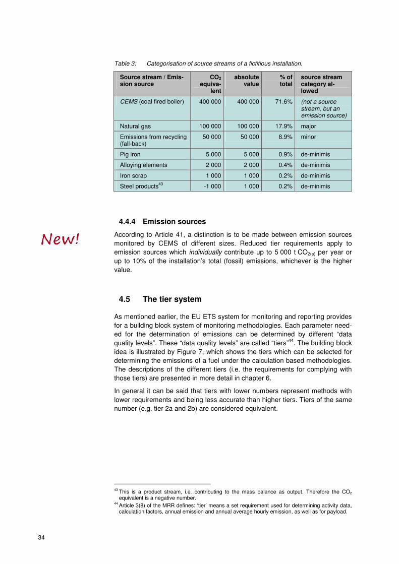
34
Table 3: Categorisation of source streams of a fictitious installation.
Source stream / Emis-sion source
CO2 equiva-
lent
absolute value
% of total
source stream category al-lowed
CEMS (coal fired boiler) 400 000 400 000 71.6% (not a source stream, but an emission source)
Natural gas 100 000 100 000 17.9% major
Emissions from recycling (fall-back)
50 000 50 000 8.9% minor
Pig iron 5 000 5 000 0.9% de-minimis
Alloying elements 2 000 2 000 0.4% de-minimis
Iron scrap 1 000 1 000 0.2% de-minimis
Steel products43
-1 000 1 000 0.2% de-minimis
4.4.4 Emission sources
According to Article 41, a distinction is to be made between emission sources
monitored by CEMS of different sizes. Reduced tier requirements apply to
emission sources which individually contribute up to 5 000 t CO2(e) per year or
up to 10% of the installation’s total (fossil) emissions, whichever is the higher
value.
4.5 The tier system
As mentioned earlier, the EU ETS system for monitoring and reporting provides
for a building block system of monitoring methodologies. Each parameter need-
ed for the determination of emissions can be determined by different “data
quality levels”. These “data quality levels” are called “tiers”44
. The building block
idea is illustrated by Figure 7, which shows the tiers which can be selected for
determining the emissions of a fuel under the calculation based methodologies.
The descriptions of the different tiers (i.e. the requirements for complying with
those tiers) are presented in more detail in chapter 6.
In general it can be said that tiers with lower numbers represent methods with
lower requirements and being less accurate than higher tiers. Tiers of the same
number (e.g. tier 2a and 2b) are considered equivalent.
43
This is a product stream, i.e. contributing to the mass balance as output. Therefore the CO2 equivalent is a negative number.
44 Article 3(8) of the MRR defines: ‘tier’ means a set requirement used for determining activity data, calculation factors, annual emission and annual average hourly emission, as well as for payload.
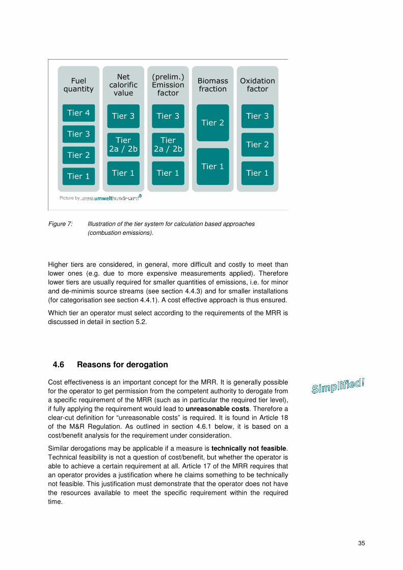
35
Fuel quantity
Tier 4
Tier 3
Tier 2
Tier 1
Net calorific value
Tier 3
Tier 2a / 2b
Tier 1
(prelim.) Emission factor
Tier 3
Tier 2a / 2b
Tier 1
Biomass fraction
Tier 2
Tier 1
Oxidation factor
Tier 3
Tier 2
Tier 1
Picture by
Figure 7: Illustration of the tier system for calculation based approaches
(combustion emissions).
Higher tiers are considered, in general, more difficult and costly to meet than
lower ones (e.g. due to more expensive measurements applied). Therefore
lower tiers are usually required for smaller quantities of emissions, i.e. for minor
and de-minimis source streams (see section 4.4.3) and for smaller installations
(for categorisation see section 4.4.1). A cost effective approach is thus ensured.
Which tier an operator must select according to the requirements of the MRR is
discussed in detail in section 5.2.
4.6 Reasons for derogation
Cost effectiveness is an important concept for the MRR. It is generally possible
for the operator to get permission from the competent authority to derogate from
a specific requirement of the MRR (such as in particular the required tier level),
if fully applying the requirement would lead to unreasonable costs. Therefore a
clear-cut definition for “unreasonable costs” is required. It is found in Article 18
of the M&R Regulation. As outlined in section 4.6.1 below, it is based on a
cost/benefit analysis for the requirement under consideration.
Similar derogations may be applicable if a measure is technically not feasible.
Technical feasibility is not a question of cost/benefit, but whether the operator is
able to achieve a certain requirement at all. Article 17 of the MRR requires that
an operator provides a justification where he claims something to be technically
not feasible. This justification must demonstrate that the operator does not have
the resources available to meet the specific requirement within the required
time.
36
4.6.1 Unreasonable costs
When assessing whether costs for a specific measure are reasonable, the costs
are to be compared with the benefit it would give. Costs are considered unrea-
sonable where the costs exceed the benefit (Article 18). The detailed descrip-
tion of the cost-benefit analysis is a new element in the MRR.
Costs: It is up to the operator to provide a reasonable estimation of the costs
involved. Only costs which are additional to those applicable for the alternative
scenario should be taken into account. The MRR also requires that the equip-
ment costs are to be assessed using a depreciation period appropriate for the
economic lifetime of the equipment. Thus, the annual costs during the lifetime
rather than the total equipment costs are to be used in the assessment.
Example: An old measuring instrument is found to not function properly any
more, and is to be exchanged for a new one. The old instrument has allowed
reaching an uncertainty of 3% corresponding to tier 2 (±5%) for activity data (for
tier definitions see section 6.1.1). Because the operator would have to apply a
higher tier anyway, he considers whether a better instrument would incur un-
reasonable costs. Instrument A costs 40 000 € and leads to an uncertainty of
2.8% (still tier 2), instrument B costs 70 000 €, but allows an uncertainty of 2.1%
(tier 3, ±2.5%). Due to the rough environment in the installation, a depreciation
period of 5 years is considered appropriate.
The costs to be taken into account for the assessment of unreasonable costs
are 30 000 € (i.e. the difference between the two meters) divided by 5 years, i.e.
6 000 €. No cost for the working time should be considered, as the same work-
load is assumed to be necessary independent from the type of the meter to be
installed. Also same maintenance costs can be assumed as approximation.
Benefit: As the benefit of e.g. more precise metering is difficult to express in fi-
nancial values, an assumption is to be made following the MRR. The benefit is
considered to be proportionate to an amount of allowances in the order of mag-
nitude of the reduced uncertainty. In order to make this estimation independent
from daily price fluctuations, the MRR requires a constant allowance price of
20 € to be applied. For determining the assumed benefit, this allowance price is
to be multiplied by an “improvement factor”, which is the improvement of uncer-
tainty multiplied by the average annual emissions caused by the respective
source stream45
over the three most recent years46
. The improvement of uncer-
tainty is the difference between the uncertainty currently achieved47
and the un-
certainty threshold of the tier which would be achieved after the improvement.
Where no direct improvement of the accuracy of emissions data is achieved by
an improvement, the improvement factor is always 1%. Article 18(3) lists some
of such improvements, e.g. switching from default values to analyses, increas-
45
Where one measuring instrument is used for several source streams, such as a weighbridge, the sum of emissions of all related source streams should be used.
46 Only the fossil emissions are considered. Transferred CO2 is not subtracted. Where the most av-erage emissions of the most recent three years are not available or not applicable due to technical changes, a conservative estimate is to be used.
47 Please note that the “real” uncertainty is meant here and not uncertainty threshold of the tier.
37
ing the number of samples analysed, improving the data flow and control sys-
tem, etc.
Please note the minimum threshold introduced by the MRR: Accumulated im-
provement costs below 2 000 € per year are always considered reasonable,
without assessing the benefit. For installations with low emissions (� section
4.4.2) this threshold is only 500 €.
Summarizing the above by means of a formula, the costs are considered rea-
sonable, if:
( )
tiernewcurr UUAEmPC −⋅⋅< (9)
Where:
C ......... Costs [€/year]
P ......... specified allowance price = 20 € / t CO2(e)
AEm .... Average emissions from related source stream(s) [t CO2(e)/year]
Ucurr ..... Current uncertainty (not the tier) [%]
Unew tier . Uncertainty threshold of the new tier that can be reached [%]
Example: For the replacement of meters described above, the benefit of “im-
provement” for instrument A is zero, as it is a mere replacement maintaining the
current tier. It cannot be unreasonable, as the installation cannot be operated
without at least this instrument.
In case of instrument B, tier 3 (threshold uncertainty = 2.5 %) can be reached.
Thus, the uncertainty improvement is Ucurr – Unew tier = 2.8% – 2.5% = 0.3%.
The average annual emissions are AEm = 120 000 t CO2/year. Therefore, the
assumed benefit is 0.003 ·120 000 ·20 € =7 200 €. This is higher than the as-
sumed costs (see above). It is therefore not unreasonable to require instrument
B installed.

38
4.7 Uncertainty
When somebody would like to ask the basic question about the quality of the
MRV system of any emission trading system, he would probably ask: “How
good is the data?” or rather “Can we trust the measurements which produce the
emission data?” When determining the quality of measurements, international
standards refer to the quantity of “uncertainty”. This concept needs some expla-
nation.
There are different terms frequently used in a similar way as uncertainty. How-
ever, these are not synonyms, but have their own defined meaning (see also il-
lustration in Figure 8):
� Accuracy: This means closeness of agreement between a measured val-
ue and the true value of a quantity. If a measurement is accurate, the aver-
age of the measurement results is close to the “true” value (which may be
e.g. the nominal value of a certified standard material48
). If a measurement
is not accurate, this can sometimes be due to a systematic error. Often this
is can be overcome by calibrating and adjustment of instruments.
� Precision: This describes the closeness of results of measurements of the
same measured quantity under the same conditions, i.e. the same thing is
measured several times. It is often quantified as the standard deviation of
the values around the average. It reflects the fact that all measurements
include a random error, which can be reduced, but not completely eliminat-
ed.
� Uncertainty49
: This term characterizes the range within which the true val-
ue is expected to lie with a specified level of confidence. It is the overarch-
ing concept which combines precision and assumed accuracy. As shown in
Figure 8, measurements can be accurate, but imprecise, or vice versa. The
ideal situation is precise and accurate.
If a laboratory assesses and optimizes its methods, it usually has an interest in
distinguishing accuracy and precision, as this leads the way to identification of
errors and mistakes. It can show such diverse reasons for errors such as the
need for maintenance or calibration of instruments, or for better training of staff.
However, the final user of the measurement result (in the case of the ETS, this
is the operator and the competent authority) simply wants to know how big the
interval is (measured average ± uncertainty), within which the true value is
probably found.
In the EU ETS, only one value is given for the emissions in the annual emis-
sions report. Only one value is entered in the verified emissions table of the reg-
istry. The operator can’t surrender “N ± x%” allowances, but only the precise
value N. It is therefore clear that it is in everybody’s interest to quantify and re-
duce the uncertainty “x” as far as possible. This is the reason why monitoring
plans must be approved by the competent authority, and why operators have to
48
Also a standard material, such as e.g. a copy of the kilogram prototype, disposes of an uncertain-ty due to the production process. Usually this uncertainty will be small compared to the uncertain-ties later down in its use.
49 The MRR defines in Article 3(6): ‘uncertainty’ means a parameter, associated with the result of the determination of a quantity, that characterises the dispersion of the values that could reasonably be attributed to the particular quantity, including the effects of systematic as well as of random factors, expressed in per cent, and describes a confidence interval around the mean value com-prising 95% of inferred values taking into account any asymmetry of the distribution of values.
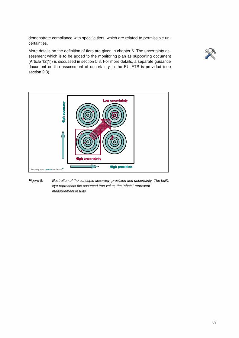
39
demonstrate compliance with specific tiers, which are related to permissible un-
certainties.
More details on the definition of tiers are given in chapter 6. The uncertainty as-
sessment which is to be added to the monitoring plan as supporting document
(Article 12(1)) is discussed in section 5.3. For more details, a separate guidance
document on the assessment of uncertainty in the EU ETS is provided (see
section 2.3).
Picture by
Hig
h a
ccu
rac
y
High precision
High uncertainty
Low uncertainty
Picture byPicture by
Hig
h a
ccu
rac
y
High precision
High uncertainty
Low uncertainty
Hig
h a
ccu
rac
y
High precision
High uncertainty
Low uncertainty
Figure 8: Illustration of the concepts accuracy, precision and uncertainty. The bull’s
eye represents the assumed true value, the “shots” represent
measurement results.

40
5 THE MONITORING PLAN
This chapter describes the way an operator can develop a monitoring plan from
scratch. This will be the case for few installations only, i.e. for new installations,
including installations which will be included in the EU ETS from 2013 for the
first time. However, due to the transition from the MRG 2007 to the M&R Regu-
lation, operators will have to revise the monitoring plans of all installations, in
order to identify gaps or relevant improvement possibilities. Therefore this chap-
ter will also be valuable for existing installations. Where significant changes
compared to the MRG 2007 have been introduced by the MRR, this is high-
lighted in the text specifically with the usual icons.
5.1 Developing a monitoring plan
When developing a monitoring plan, operators should follow some guiding prin-
ciples:
� Knowing in detail the situation of their own installation, the operator should
make the monitoring methodology as simple as possible. This is achieved
by attempting to use the most reliable data sources, robust metering in-
struments, short data flows, and effective control procedures.
� Operators should imagine their annual emission report from verifier’s per-
spective. What would a verifier ask about how the data has been com-
piled? How can the data flow be made transparent? Which controls prevent
errors, misrepresentations, omissions?
� Because installations usually undergo technical changes over the years,
monitoring plans must be considered living documents to a certain extent.
In order to minimise administrative burden, operators should be careful
which elements must be laid down in the monitoring plan itself, and what
can be put into written procedures supplementing the MP.
Note: for installations with small emissions and some other “simple” in-
stallations, this chapter is only partly relevant. It is advisable to consult
first chapter 7 of this document.
The following step-by-step approach might be considered helpful:
1. Define the installation’s boundaries. Operators of incumbent installations
should be aware that the scope of the EU ETS Directive (its Annex I) has
been updated during the EU ETS review50
. Therefore the boundaries should
be re-evaluated before the start of the new ETS period in 2013.
2. Determine the installation’s category (� see section 4.4.1) based on an es-
timate of the installation’s annual GHG emissions. Where the boundaries of
an incumbent are unchanged, the average verified annual emissions of the
previous years can be used. In other situations, a conservative estimate is
needed.
50
See the Commission’s guidance document on the interpretation of the new Annex I: http://ec.europa.eu/clima/policies/ets/docs/guidance_interpretation_en.pdf
small

41
3. List all emission sources and source streams (� for definitions see section
4.2) in order to decide on calculation or measurement based approach.
Classify the source streams as major, minor and de-minimis as appropriate.
4. Identify the tier requirements based on the installation category (see section
5.2). Note that the system of required tiers has been significantly changed
from the MRG 2007 to the MRR.
5. List and assess potential sources of data:
a. For activity data (for detailed requirements see section 6.1. Note that
Articles 27 to 29 bring significant changes compared to the MRG, when
it comes to assessing if the uncertainty is met as required for meeting
specific tiers):
i. How can the amount of fuel or material be determined?
• Are there instruments for continual metering, such as flow me-
ters, weighing belts etc. which give direct results for the
amount of material entering or leaving the process over time?
• Or must the fuel or material quantity be based on batches
purchased? In this case, how can the quantity on stock piles
or in tanks at the end of the year be determined?
ii. Are measuring instruments owned/controlled by the operator avail-
able?
• If yes: What is their uncertainty level? Are they difficult to cali-
brate? Are they subject to legal metrological control51
?
• If no: Can measuring instruments be used, which are under
the control of the fuel supplier? (This is often the case for gas
meters, and for many cases where quantities are determined
based on invoices.)
iii. Estimate uncertainty associated with those instruments and deter-
mine the achievable tier associated. Note: For uncertainty assess-
ment several simplifications are applicable, in particular if the
measuring instrument is subject to national legal metrological con-
trol. For details see guidance document No. 4 (see section 2.3).
b. Calculation factors (NCV, emission factor or carbon content, oxidation
or conversion factor, biomass fraction): Depending on the required tiers
(which are determined based on installation category and source
stream category):
i. Are default values applicable? If yes, are values available? (Annex
VI of the MRR, publications of the competent authority, national in-
ventory values)?
ii. If the highest tiers are to be applied, or if no default values are ap-
plicable, chemical analyses have to be carried out for determining
the missing calculation factors. In this case the operator must
51
Some measuring instruments used for commercial transactions are subject to national legal met-rological control. Special requirements (simplified approaches) are applicable to such instruments under the MRR. See guidance document No. 4 (see section 2.3) for details.
42
• Decide on the laboratory to be used. If no accredited laborato-
ry52
is available, establish evidence on the equivalence to ac-
creditation (see section 6.2.2);
• Select the appropriate analytical method (and applicable
standard);
• Design a sampling plan (see guidance document No. 5 (see
section 2.3)).
6. Can all required tiers be met? If not, can a lower tier be met, if allowed in
accordance with technical feasibility and unreasonable costs (� section
4.6)?
7. Will measurement based approaches (CEMS, see sections 4.3.3 and 8) be
used53
? Can the relevant tiers and other requirements be complied with?
(Note that the requirements for using CEMS have been significantly
changed compared to the MRG 2007.)
8. If answers for points 6 and 7 are negative: Is there a way of using a fall-
back methodology (see section 4.3.4)? A full uncertainty assessment for the
installation is required in this case.
9. Next the operator should define all data flows (who takes which data from
where, does what with the data, hands over the results to whom, etc.) from
the measuring instruments or invoices to the final annual report. The design
of a flow diagram will be helpful. More details on data flow activities are
found in section 5.5.
10. With this overview of the data sources and data flows, the operator can car-
ry out a risk analysis (see section 5.5). Thereby he will determine where in
the system errors might occur most easily.
11. Using the risk analysis, the operator should:
a. If applicable, decide whether CEMS or calculation based approaches
are more suitable;
b. Assess which measuring instruments and data sources to use for activi-
ty data (see point 5.a above). In case of several possibilities, the one
with the lowest uncertainty and lowest risk should be used;
c. In all other cases which need decisions54
, decide based on the lowest
associated risk; and
d. Define control activities for mitigating the identified risks (see section
5.5).
12. It may be necessary to repeat some of the steps 5 to 11, before finally writ-
ing down the monitoring plan and the related procedures. In particular, the
risk analysis will need update after having the control activities defined.
52
„Accredited laboratory“ is used here as short form of “a laboratory which has been accredited pur-suant to EN ISO/IEC 17025 for the analytical method required”.
53 CEMS must be used for N2O emissions, and may be used for CO2 emissions. If the requirements for calculation based methods for CO2 cannot be reached, CEMS should be considered as equal-ly valid alternative.
54 E.g. where several departments could handle the data, choose the most suitable with the lowest number of error possibilities.
43
13. Then the operator will write the monitoring plan (using the templates provid-
ed by the Commission, an equivalent template by a Member State or a ded-
icated IT system provided by a Member State), and the supporting docu-
ments required (Article 12(1)):
a. Evidence that all the tiers noted in the monitoring plan are complied with
(this requires an uncertainty assessment, which can be very simple in
most cases, see section 5.3);
b. The result of the final risk analysis (�section5.5), showing that the de-
fined control system is appropriately mitigating the identified risks;
c. Further documents (such as installation description and diagram) may
need to be attached;
d. The written procedures referenced by the MP need to be developed,
but do not need to be attached to the MP when submitting it to the CA
(see section 5.4 on procedures).
The operator should make sure that all versions of the monitoring plan, the re-
lated documents and procedures are clearly identifiable, and that the most re-
cent versions are always used by all staff involved. A good document manage-
ment system is advisable from the beginning.
5.2 Selecting the correct tier
Compared to the MRG 2007, the system of defining the minimum required tiers
has been significantly changed. The new system is laid down in Article 26 for
calculation based approaches (i.e. for standard methodology and mass balanc-
es). The overarching rule is that the operator should apply the highest tier
defined for each parameter55
. For major source streams within Category B
and C installations this is mandatory. For other source streams and smaller in-
stallations, the following set of rules defines the exceptions from the rule:
1. Instead of the highest tiers defined, category A installations are required to
apply at least the tiers specified in Annex V of the MRR for major source
streams.
2. Regardless of the installation category, the same tiers of Annex V are appli-
cable for commercial standard fuels56
with regard to calculation factors.
3. Where the operator demonstrates to the satisfaction of the competent au-
thority, that applying the tiers required by the previous points leads to un-
55
In fact, this rule is not new, but has been existing already since the MRG 2004. However, the rule has been softened on an interim basis for the first two phases.
56 Article 3(31) defines: ‘commercial standard fuel’ means the internationally standardised commer-cial fuels which exhibit a 95% confidence interval of not more than 1% for their specified calorific value, including gas oil, light fuel oil, gasoline, lamp oil, kerosene, ethane, propane, butane, jet kerosene (jet A1 or jet A), jet gasoline (Jet B) and aviation gasoline (AvGas). Commercial standard fuels are considered easy to monitor. Therefore Article 31(4) allows the same treatment also for other fuels which exhibit similar constant composition: “Upon application by the operator, the competent authority may allow that the net calorific value and emission fac-tors of fuels are determined using the same tiers as required for commercial standard fuels pro-vided that the operator submits, at least every three years, evidence that the 1% interval for the specified calorific value has been met during the last three years”.
44
reasonable costs (� section 4.6) or is technically not feasible (� section
4.6), the operator may apply a tier which is
� one tier lower in case of category C installations;
� one or two tiers lower in case of category B and A installations;
Tier 1 is always the lowest possible tier.
4. Where the tier levels required by the previous point are still technically not
feasible or involving unreasonable costs, the CA may allow the operator to
apply an even lower tier (with a minimum of tier 1) for a transitional time of
not more than three years, if the operator provides a suitable plan for nec-
essary improvement within this period.
The above is applicable to major source streams. For minor source streams,
lower tiers are allowed in general. The MRR therefore states that the highest ti-
er that is technically feasible and not incurring unreasonable costs may be ap-
plied with a minimum of tier 1. This means that the operator should first investi-
gate which tier level is actually applied or can easily be applied. This tier is then
laid down in the monitoring plan57
.
Operators are expected to apply tiers equal or higher than 1 also for de-
minimis source streams where this can be achieved “without additional effort”
(i.e. without any notable costs). However, cases may exist where even tier 1 will
involve significant or even unreasonable costs. For those cases the MRR allows
that the operator applies a conservative58
estimation method (this is a “no-tier
method”). The operator should describe this method in the monitoring plan.
Special rules are applicable to calculation factors in some cases:
� For oxidation and conversion factors, the operator may apply in all types of
installations tier 1 (i.e. setting the factor to a value of 100%)59
.
� For some methodologies, the net calorific value (NCV) of fuels is not re-
quired for calculation, but is to be reported for consistency reasons only.
According to Article 26(5) this is the case for:
� Fuels where the CA has allowed to use emission factors expressed as
t CO2 per tonne (or Nm3) instead of t CO2/TJ;
� Fuels which are used as process input (if the emission factor is not
expressed as per TJ);
� Fuels which are part of a mass balance as described in section 4.3.2.
In these cases the NCV may be determined using a lower tier than the
highest, i.e. any of the tiers 1, 2a and 2b. However, the highest tier which
does not involve additional efforts should be applied.
The full system of tier selection requirements for calculation based approaches
is summarized by Table 4.
57
It is to be noted that the monitoring plan always has to reflect the tier actually applied, not the min-imum one required. The general principle is that operators should attempt to improve their moni-toring systems wherever possible.
58 “Conservative” means that the method shall not lead to underestimation of the emissions.
59 This is the “translation” of the MRR text of Article 26(4), which requires “the lowest tiers listed in Annex II, as a minimum”.
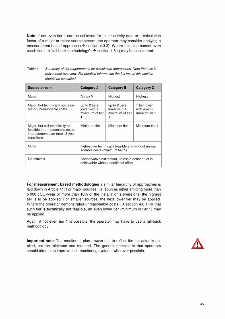
45
Note: If not even tier 1 can be achieved for either activity data or a calculation
factor of a major or minor source stream, the operator may consider applying a
measurement based approach (� section 4.3.3). Where this also cannot even
reach tier 1, a “fall-back methodology” (� section 4.3.4) may be considered.
Table 4: Summary of tier requirements for calculation approaches. Note that this is
only a brief overview. For detailed information the full text of this section
should be consulted.
Source stream Category A Category B Category C
Major Annex V Highest Highest
Major, but technically not feasi-ble or unreasonable costs
up to 2 tiers lower with a minimum of tier 1
up to 2 tiers lower with a minimum of tier 1
1 tier lower with a mini-mum of tier 1
Major, but still technically not feasible or unreasonable costs; improvement plan (max. 3 year transition)
Minimum tier 1 Minimum tier 1 Minimum tier 1
Minor highest tier technically feasible and without unrea-sonable costs (minimum tier 1)
De-minimis Conservative estimation, unless a defined tier is achievable without additional effort
For measurement based methodologies a similar hierarchy of approaches is
laid down in Article 41: For major sources, i.e. sources either emitting more than
5 000 t CO2/year or more than 10% of the installation’s emissions, the highest
tier is to be applied. For smaller sources, the next lower tier may be applied.
Where the operator demonstrates unreasonable costs (� section 4.6.1) or that
such tier is technically not feasible, an even lower tier (minimum is tier 1) may
be applied.
Again, if not even tier 1 is possible, the operator may have to use a fall-back
methodology.
Important note: The monitoring plan always has to reflect the tier actually ap-
plied, not the minimum one required. The general principle is that operators
should attempt to improve their monitoring systems wherever possible.
46
5.3 Uncertainty assessment as supporting document
5.3.1 General requirements
As shown in section 6.1.1, the tiers for activity data are expressed using a spec-
ified “maximum permissible uncertainty over a reporting period”. When submit-
ting a new or updated monitoring plan, the operator must demonstrate the com-
pliance of his monitoring methodology (in particular of the measuring instru-
ments applied) with those uncertainty levels. Pursuant to Article 12(1), this is
done by submitting an uncertainty assessment as supporting document togeth-
er with the monitoring plan. (Note: installations with low emissions (� section
4.4.2) are exempt from this requirement).
This supporting document should contain the following information:
� Evidence for compliance with uncertainty thresholds for activity data;
� Evidence for compliance with uncertainty required for calculation factors, if
applicable60
;
� Evidence for compliance with uncertainty requirements for measurement
based methodologies, if applicable;
� If a fall-back methodology is applied for at least part of the installation, an
uncertainty assessment for the total emissions of the installation is to be
presented.
It is advisable that the operator designs at the same time a pragmatic procedure
for repeating this assessment regularly61
.
For activity data, the assessment shall comprise (Article 28(2), by way of analo-
gy also required by Article 29):
� the specified uncertainty of the applied measuring instruments,
� uncertainty associated with the calibration, and
� any additional uncertainty connected to how the measuring instruments are
used in practice.
� Furthermore the influence of the uncertainty related to determination of
stocks at the start/end of the year are to be included, if relevant. They are
relevant if:
� fuel or material quantities are determined based on batch measure-
ments rather than continual metering, i.e. mostly when invoices are
used,
� storage facilities are capable of containing at least 5% of the annual
used quantity of the fuel or material considered; and
� the installation is not an installation with low emissions (� section
4.4.2)
60
This is applicable only where the sampling frequency for analyses is determined based on the rule of 1/3 of the activity data uncertainty (Article 35(2)). For more information see section 6.2.2.
61 Such procedure is to be referenced in the monitoring plan in accordance with Annex I, section 1, point 1(c)(ii), and is needed for compliance with Articles 28(1), and 22, if applicable.

47
5.3.2 Simplifications
As mentioned above in this section and in section 4.7, uncertainty encom-
passes several sources of uncertainty, in particular errors which are caused by
a lack of precision (in principle this is the meter’s uncertainty as specified by the
manufacturer for use in an appropriate environment, and certain conditions for
installation, such as length of straight piping before and after a flow meter) and
a lack of accuracy (e.g. caused by aging or corrosion of the instrument, which
may result in a drift). Therefore the MRR calls for the uncertainty assessment to
take account of measuring instrument’s uncertainty, as well as influence from
calibration and all other possible influencing parameters. However, in practice
such uncertainty assessment is very demanding, and exceeds the possibilities
of many operators’ resources. The MRR therefore provides for several pragmat-
ic simplifications.
5.3.2.1 Simplification based on ETSG approach
For the second EU ETS phase, the so-called ETSG guidance document pro-
posed a simplified approach, which allowed the overall uncertainty for a source
stream’s activity data to be approximated by the uncertainty known for a specific
type of instrument, under the condition that other sources of uncertainty are suf-
ficiently mitigated. This is considered to be the case in particular if the instru-
ment is installed according to certain conditions. The ETSG note contains a list
of instrument types and installation conditions which helps the user applying this
approach.
The M&R Regulation has picked up the principle of this approach and allows
the operator to use the “Maximum Permissible Error (MPE) in service”62
speci-
fied for the instrument as overall uncertainty, provided that measuring instru-
ments are installed in an environment appropriate for their use specifications.
Where no information is available for the MPE in service, or where the operator
can achieve better values than the default values, the uncertainty obtained by
calibration may be used, multiplied by a conservative adjustment factor for tak-
ing into account the higher uncertainty when the instrument is “in service”.
The information source for the MPE in service and the appropriate use specifi-
cations is not further specified by the MRR, leaving some room for flexibility. It
may be assumed that the manufacturer’s specifications, specifications from le-
gal metrological control, but also guidance documents such as the Commis-
sion’s guidance are suitable sources.
5.3.2.2 Relying on national legal metrological control
The second simplification allowed by the MRR, is even more simplifying in prac-
tice: Where the operator demonstrates to the satisfaction of the CA, that a
measuring instrument is subject to national legal metrological control, the MPE
62
The MPE in service is significantly higher than the MPE of the new instrument. The MPE in ser-vice is often expressed as a factor times the MPE of the new instrument.
48
(in service) allowed by the metrological control legislation may be taken as un-
certainty, without providing further evidence63
.
5.3.2.3 Installations with low emissions
Article 47(4) and (5) exempt operators of installations with low emissions (�
section 4.4.2) completely from delivering an uncertainty assessment, where ac-
tivity data is based on purchase records.
5.3.3 Further guidance
The topic of uncertainty assessment, and related topics such as default values
for MPEs and use conditions of frequently used instrument types, are dealt with
by guidance document No. 4 (see section 2.3).
5.4 Procedures and the monitoring plan
The monitoring plan should ensure that the operator carries out all the monitor-
ing activities consistently over the years, like according to a recipe book. In or-
der to prevent incompleteness, or arbitrary changes by the operator, the compe-
tent authority’s approval is required. However, there are always elements in the
monitoring activities, which are less crucial, or which may change frequently.
The M&R Regulation provides a useful tool for such situations: Such monitoring
activities may (or even shall) be put into “written procedures”64
, which are men-
tioned and described briefly in the MP, but are not considered part of the MP.
These procedures are tightly linked to, but not part of the monitoring plan. They
must be just described in the MP with such level of detail that the CA can un-
derstand the content of the procedure, and can reasonably assume that a full
documentation of the procedure is maintained and implemented by the opera-
tor. The full text of the procedure would be delivered to the competent authority
only upon request. The Operator shall also make procedures available for the
purposes of verification (Article 12(2)). As a result, the operator has the full re-
sponsibility for the procedure. This gives him the flexibility to make amendments
to the procedure whenever needed, without requiring update of the monitoring
plan, as long as the procedure’s content stays within the limitations of its de-
scription laid down in the monitoring plan.
The MRR contains several elements which are by default expected to be put in-
to written procedures, such as:
� Managing responsibilities and competency of personnel;
� Data flow and control procedures (� section 5.5);
� Quality assurance measures;
63
The philosophy behind this approach is that control is exerted here not by the CA responsible for the EU ETS, but by another authority which is in charge of the metrological control issues. Thus, double regulation is avoided and administration is reduced.
64 Article 11(1) 2
nd sub-paragraph: “The monitoring plan shall be supplemented by written proce-
dures which the operator or aircraft operator establishes, documents, implements and maintains for activities under the monitoring plan, as appropriate.”
small
49
� Estimation method for substitution data where data gaps have been found;
� Regular review of the monitoring plan for its appropriateness (including un-
certainty assessment where relevant);
� A sampling plan65
, if applicable (� see section 6.2.2), and a procedure for
revising the sampling plan, if relevant;
� Procedures for methods of analyses, if applicable;
� Procedure for demonstrating evidence for equivalence to EN ISO/IEC
17025 accreditation of laboratories, if relevant;
� Procedure for uncertainty assessment in case of fall-back methodologies
(� section 4.3.4) applied;
� Procedures for use of measurement based methodologies, including for
corroborating calculations and for subtracting biomass emissions, if rele-
vant;
� Only if the Member State requires this: A procedure for ensuring that the
requirements of Article 24(1) of the CIMs are met.
The MRR furthermore outlines how the procedure must be described in the
Monitoring plan. Note that for simple installations also the procedures will usual-
ly be very simple and straightforward. Where the procedure is very simple, it
may be useful to use the procedure text immediately as “description” of the pro-
cedure as required for the monitoring plan.
Example for a procedure:
An operator might apply different fractions of municipal or industrial waste as
fuel. If every type of waste were to be considered as individual source stream,
the operator would have to update the monitoring plan every time a new waste
is delivered. The competent authority would be required to issue an approval of
the monitoring plan each time. Thus, such situation cannot be considered
practical, in particular if the monitoring method is always the same (e.g. same
balance used, same sampling and analyses methods applied).
Note: This example is without prejudice to other legal requirements regarding
burning of waste, such as requirements under the Industrial Emissions Directive
(IED, Directive 2010/75/EU). This example assumes that the different types of
waste mentioned do not infringe any permit conditions or other legal
requirements. The focus here lies purely on the EU ETS monitoring aspects.
Solution for monitoring: The operator uses a procedure for checking if the waste
delivered fits into the boundaries of the defined source stream before applying
the monitoring approach defined in the monitoring plan. The procedure could be
outlined like this:
1. The shift personnel at entrance gate is instructed to report every delivery of
a waste material to the RSM (ETS Responsible Shift Manager)66
.
2. RSM checks if waste delivered complies with quality standard as defined by
<procedure x.y.1>. That procedure defines:
65
Containing information on the methodologies for preparation of samples, including information on responsibilities, locations, frequencies and quantities and methodologies for the storage and transport of samples (Article 33).
66 Note that not the name of responsible persons, but the name of the post is to be used, in order to avoid necessary updates whenever persons change.

50
a. that only waste of certain waste catalogue numbers are permitted by
the CA,
b. only certain net calorific values, humidity and particle size can be used
in the installation;
c. In case of doubt, RSM will request the on-site laboratory to perform
adequate analyses.
3. If the waste does not comply with <procedure x.y.1>, it has to be put on
storage until the calculation factors have been determined. In this case this
waste is put on a list of new materials, which will be notified to the CA every
year in the first week of November.
4. Thereafter the waste can be used in the installation. The mass noted down
on the delivery note, as well as the calculation factors are entered in the
ETS data log, filename “E:\Raw data\SourceStreamData.xls”, sheet
“WasteLog” by RSM.
<End of procedure>
Table 5 and Table 6 outline the necessary elements of information required to
be put into the monitoring plan for each procedure (Article 12(2)), and give
examples for procedures.
Table 5: Example related to the management of staff: Descriptions of a written
procedure as required in the monitoring plan.
Item according to Article 12(2) Possible content (examples)
Title of the procedure ETS personnel management
Traceable and verifiable reference for identification of the procedure
ETS 01-P
Post or department responsible for im-plementing the procedure and the post or department responsible for the manage-ment of the related data (if different)
HSEQ deputy head of unit
Brief description of the procedure67
• Responsible person maintains a list of personnel involved in ETS data man-agement
• Responsible person holds at least one meeting per year with each involved person, at least 4 meetings with key staff as defined in the annex of the procedure; Aim: Identification of train-ing needs
• Responsible person manages internal and external training according to identified needs.
67
This description is required to be sufficient clear to allow the operator, the competent authority and the verifier to understand the essential parameters and operations performed.
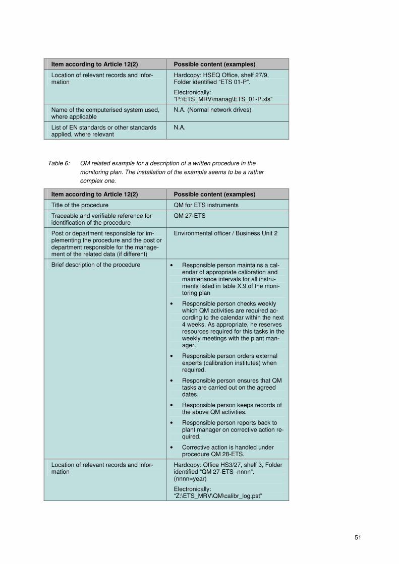
51
Item according to Article 12(2) Possible content (examples)
Location of relevant records and infor-mation
Hardcopy: HSEQ Office, shelf 27/9, Folder identified “ETS 01-P”.
Electronically: “P:\ETS_MRV\manag\ETS_01-P.xls”
Name of the computerised system used, where applicable
N.A. (Normal network drives)
List of EN standards or other standards applied, where relevant
N.A.
Table 6: QM related example for a description of a written procedure in the
monitoring plan. The installation of the example seems to be a rather
complex one.
Item according to Article 12(2) Possible content (examples)
Title of the procedure QM for ETS instruments
Traceable and verifiable reference for identification of the procedure
QM 27-ETS
Post or department responsible for im-plementing the procedure and the post or department responsible for the manage-ment of the related data (if different)
Environmental officer / Business Unit 2
Brief description of the procedure • Responsible person maintains a cal-endar of appropriate calibration and maintenance intervals for all instru-ments listed in table X.9 of the moni-toring plan
• Responsible person checks weekly which QM activities are required ac-cording to the calendar within the next 4 weeks. As appropriate, he reserves resources required for this tasks in the weekly meetings with the plant man-ager.
• Responsible person orders external experts (calibration institutes) when required.
• Responsible person ensures that QM tasks are carried out on the agreed dates.
• Responsible person keeps records of the above QM activities.
• Responsible person reports back to plant manager on corrective action re-quired.
• Corrective action is handled under procedure QM 28-ETS.
Location of relevant records and infor-mation
Hardcopy: Office HS3/27, shelf 3, Folder identified “QM 27-ETS -nnnn”. (nnnn=year)
Electronically: “Z:\ETS_MRV\QM\calibr_log.pst”

52
Item according to Article 12(2) Possible content (examples)
Name of the computerised system used, where applicable
MS Outlook calendar, also used for stor-ing documents as attachments chrono-logically
List of EN standards or other standards applied, where relevant
In the instrument list (document ETS-Instr-A1.xls) the applicable standards are listed. This document is made available to the CA and verifier upon request.
53
5.5 Data flow and control system
Monitoring of emissions data is more than just reading instruments or carrying
out chemical analyses. It is of utmost importance to ensure that data are pro-
duced, collected, processed and stored in a controlled way. Therefore the oper-
ator must define instructions for “who takes data from where and does what with
the data”. These “data flow activities” (Article 57) form part of the monitoring
plan (or are laid down in written procedures, where appropriate (see section
5.4). A data flow diagram is often a useful tool for analysing and/or setting up
data flow procedures. Examples for data flow activities include reading from in-
struments, sending samples to the laboratory and receiving the results, aggre-
gating data, calculating the emissions from various parameters, and storing all
relevant information for later use.
As human beings (and often different information technology systems) are in-
volved, mistakes in these activities can be expected. The M&R Regulation
therefore requires the operator to establish an effective control system (Arti-
cle 58). This consists of two elements:
� A risk assessment, and
� Control activities for mitigating the risks identified.
“Risk” is a parameter which takes into account both, the probability of an inci-
dent and its impact. In terms if emission monitoring, the risk refers to the proba-
bility of a misstatement (omission, misrepresentation or error) being made, and
its impact in terms of annual emissions figure.
When the operator carries out a risk assessment, he analyses for each point in
the data flow needed for the whole installation’s emission monitoring, whether
there would be a risk of misstatements. Usually this risk is expressed by qualita-
tive parameters (low, medium, high) rather than by trying to assign exact fig-
ures. He furthermore assesses potential reasons for misstatements (such as
paper copies being transported from one department to another, where delays
may occur, or copy & paste errors may be introduced), and identifies which
measures might reduce the found risks, e.g. sending data electronically and
storing a paper copy in the first department; search for duplicates or data gaps
in spreadsheets, control check by an independent person (“four eyes princi-
ple”)…
Measures identified to reduce risks are implemented. The risk assessment is
then re-evaluated with the new (reduced) risks, until the operator considers that
the remaining risks are sufficiently low for being able to produce an annual
emissions report which is free from material misstatement(s)68
.
The control activities are laid down in written procedures and referenced in the
monitoring plan. The results of the risk assessment (taking into account the con-
trol activities) are submitted as supporting documentation to the competent au-
thority when approval of the monitoring plan is requested by the operator.
68
The operator should strive to produce “error-free” emission reports (Article 7: Operators “shall ex-ercise due diligence to ensure that the calculation and measurement of emissions exhibit the highest achievable accuracy”). However, verification cannot produce 100% assurance. Instead, verification aims at providing a reasonable level of assurance that the report is free from material misstatements. For further information see the relevant guidance document on the A&V Regula-tion (see section 2.3).

54
Operators are required to establish and maintain written procedures related to
control activities for at least (Article 58(3)):
(a) quality assurance of the measurement equipment;
(b) quality assurance of the information technology system used for data flow
activities, including process control computer technology;
(c) segregation of duties in the data flow activities and control activities as well
as management of necessary competencies;
(d) internal reviews and validation of data;
(e) corrections and corrective action;
(f) control of out-sourced processes;
(g) keeping records and documentation including the management of docu-
ment versions.
Installations with low emissions: Article 47(3) exempts operators of installa-
tions with low emissions (� section 4.4.2) from submitting a risk analysis when
submitting the monitoring plan for approval by the competent authority. Howev-
er, operators will still find it useful to carry out a risk assessment for their own
purposes. It has the advantage of reducing the risk of under-reporting, under-
surrender of allowances and consequential penalties, and also over-reporting
and over-surrender.
Note that a dedicated document containing more detailed information on the da-
ta flow activities and control system (including risk analysis) is also planned.
5.6 Keeping the monitoring plan up to date
The monitoring plan must always correspond to the current nature and function-
ing of the installation. Where the practical situation at the installation is modified,
e.g. because technologies, processes, fuels, materials, measuring equipment,
IT systems, or organisation structures (i.e. staff assignments) are changed
(where relevant for the monitoring of emissions), the monitoring methodology
must be updated (Article 14)69
. Depending on the nature of the changes, one of
the following situations can occur:
� If an element of the monitoring plan itself needs updating, one of the follow-
ing situations can apply:
69
Article 14(2) lists a minimum of situations in which a monitoring plan update is mandatory: “(a) new emissions occur due to new activities carried out or due to the use of new fuels or mate-rials not yet contained in the monitoring plan; (b) the change of availability of data, due to the use of new measuring instrument types, sampling methods or analysis methods, or for other reasons, leads to higher accuracy in the determination of emissions; (c) data resulting from the previously applied monitoring methodology has been found incorrect; (d) changing the monitoring plan improves the accuracy of the reported data, unless this is techni-cally not feasible or incurs unreasonable costs; (e) the monitoring plan is not in conformity with the requirements of this Regulation and the com-petent authority requests the operator or aircraft operator to modify it; (f) it is necessary to respond to the suggestions for improvement of the monitoring plan contained in a verification report.”
small
55
� The change to the monitoring plan is a significant one. This situation is
discussed in section 5.6.1. In case of doubt, the operator has to as-
sume that the change is significant.
� The change to the monitoring plan is not significant. The procedure
described under 5.6.2 applies.
� An element of a written procedure is to be updated. If this doesn’t affect the
description of the procedure in the monitoring plan, the operator will carry
out the update under his own responsibility without notification to the com-
petent authority.
The same situations may occur as a consequence of the requirement to im-
prove the monitoring methodology continuously (see section 5.7).
The M&R Regulation in Article 16(3) also defines the requirements for record
keeping about any monitoring plan updates, such that a complete history of
monitoring plan updates is maintained, which allows a fully transparent audit
trail, including for the purposes of the verifier.
For this purpose it is considered best practice for the operator to make use of a
“logbook”, in which all non-significant changes to the monitoring plan and to
procedures are recorded, as well as all versions of submitted and approved
monitoring plans. This must be supplemented with a written procedure for regu-
lar assessment of whether the monitoring plan is up to date (Article 14(1) and
point 1(c) of section 1 of Annex I).
5.6.1 Significant changes
Whenever a significant change to the monitoring plan is necessary, the operator
shall notify the update to the competent authority without undue delay. The
competent authority then has to assess whether the change is indeed a signifi-
cant one. Article 15(3) contains a (non-exhaustive) list of monitoring plan up-
dates which are considered significant70
. If the change is not significant, the
procedure described under 5.6.2 applies. For significant changes, the compe-
tent authority thereafter carries out its normal process of approving monitoring
plans71
.
70
Article 15(3): 3. Significant modifications to the monitoring plan of an installation shall include the following: (a) changes of the category of the installation; (b) notwithstanding Article 47(8), changes regarding whether the installation is considered an in-stallation with low emissions; (c) changes to emission sources; (d) a change from calculation-based to measurement-based methodologies, or vice versa, used to determine emissions; (e) a change in the tier level applied; (f) the introduction of new source streams; (g) a change in the categorisation of source streams - between major, minor or de-minimis source streams; (h) a change of the default value for a calculation factor, where the value is to be laid down in the monitoring plan; (i) the introduction of new procedures related to sampling, analysis or calibration, where the changes of those procedures have a direct impact on the accuracy of emissions data; (j) the implementation or adaption of a quantification methodology for emissions from leakage at storage sites.
71 This process may differ between Member States. The usual procedure will include a complete-ness check for the information provided, a check for the appropriateness of the new monitoring

56
The approval process may sometimes need longer than the physical change of
the installation (e.g. where new source streams are introduced for monitoring).
Furthermore the competent authority may find the operator’s monitoring plan
update incomplete or inappropriate and may require additional amendments of
the monitoring plan. Thus, monitoring according to the old monitoring plan may
be incomplete or lead to inaccurate results, while the operator is not sure
whether the new monitoring plan will be approved as requested. The MRR pro-
vides for a pragmatic approach here:
According to Article 16(1), the operator shall immediately apply the new moni-
toring plan where he can reasonably assume that the updated monitoring plan
will be approved as proposed. This may apply e.g. when an additional fuel is in-
troduced, which will be monitored using the same tiers as comparable fuels in
that installation. Where the new monitoring plan is not yet applicable, because
the situation in the installation will change only after the approval of the monitor-
ing plan by the competent authority, monitoring is to be carried out in accord-
ance with the old monitoring plan until the new one is approved.
Where the operator is unsure whether the CA will approve the changes, he shall
carry out monitoring in parallel using both the new and the updated monitoring
plan (Article 16(1)). Upon receiving the approval of the competent authority, the
operator shall use only the data obtained in accordance with the new monitoring
plan as approved (Article 16(2)).
5.6.2 Non-significant updates of the monitoring plan
While significant updates of the monitoring plan are to be notified without undue
delay, the competent authority may allow the operator to delay the notification of
non-significant updates in order to simplify the administrative process (Article
15(1)). Where this is the case and the operator can reasonably assume that
changes to the monitoring plan are non-significant, they may be collected and
submitted to the CA once a year (by 31 December), if the competent authority
allows this approach.
The final decision on whether a change to the monitoring plan is significant is
the responsibility of the competent authority. However, an operator can reason-
ably anticipate that decision in many cases:
� Where a change is comparable to one of the cases listed in Article 15(3),
the change is significant;
� Where the impact of the proposed monitoring plan change on the overall
monitoring methodology or on the risks for error is small, it may be non-
significant;
� In case of doubt assume it is a significant change and follow section 5.6.1.
Non-significant changes do not need the approval of the competent authority.
However, in order to provide for legal certainty, the competent authority must in-
form the operator without undue delay of its decision to consider changes non-
significant where the operator has notified them as significant. Operators can be
plan in regard of the changed situation of the installation, and a check for compliance with the M&R Regulation. The competent authority may also reject the new monitoring plan or require fur-ther improvements. The competent authority may also come to the conclusion that the proposed changes are not significant ones.

57
expected to appreciate if the competent authority acknowledges receipt of noti-
fications in general.
5.7 The improvement principle
While the previous section has dealt with monitoring plan updates which are
mandated as consequence of factual changes at the installation, the MRR also
requires the operator to explore possibilities to improve the monitoring method-
ology when the installation itself is unchanged. For implementing this “improve-
ment principle”, there are two requirements:
� Operators must take account of the recommendations included in the veri-
fication reports (Article 9), and
� Operators must check regularly on their own initiative, whether the monitor-
ing methodology can be improved (Article 14(1) and Article 69(1)-(3)).
Operators must react to those findings on possible improvements by
� Sending a report on the proposed improvements to the competent authority
for approval,
� Updating the monitoring plan as appropriate (using the procedures outlined
in sections 5.6.1 and 5.6.2), and
� Implementing the improvements according to the time table proposed in
the approved improvement report.
For the improvement report responding to a verifier’s recommendations, the
deadline is 30 June of the year in which the verification report is issued. For the
improvement report on the operator’s own initiative (which may be combined
with the one on verifier’s findings) the deadline is the 30 June as well, but it has
to be delivered
� every year for category C installations,
� every two years for category B installations, and
� every four years for category A installations.
The deadline of 30 June may be extended by the competent authority up to
30 September of the same year.
Operators of installations with low emissions (� section 4.4.2) have to take into
consideration the verifier’s recommendations in their monitoring, but are ex-
empted from providing a corresponding improvement report to the competent
authority (Article 47(3)).
The improvement reports have to contain in particular the following information:
� Improvements for achieving higher tiers, if the “required” tiers are not yet
applied. “Required” here means “those tiers which are applicable if no un-
reasonable costs occur and if the tier is technically feasible”72
.
72
Those „required“ tiers are: (a) for calculation approaches (first sub-paragraph of Article 26(1)): the highest tiers defined in Annex II of the MRR for category B and C installations, and the tiers laid down in Annex V for cat-egory A installations and for calculation factors for commercial standard fuels; (b) for measurement based approaches (Article 41(1)): The highest tier for each emission source
small

58
� If the operator applies a fall-back methodology (� section 4.3.4), the report
shall contain a justification as to why it is technically not feasible or would
incur unreasonable costs to apply at least tier 1 for one or more major or
minor source streams. If this justification is not applicable any more, the
operator has to report how at least tier 1 for those source streams is to be
applied.
� The report should contain for each possible improvement either a descrip-
tion of the improvement and the related timetable, or evidence regarding
technical non-feasibility or unreasonable costs, if applicable (� section
4.6).
Note: The Commission plans to provide harmonised templates for improvement
reports.
which emits more than 5 000 tonnes of CO2(e) per year, or which contributes more than 10% of the total annual emissions of the installation; The next lower tiers for other sources.

59
6 CALCULATION BASED APPROACHES
This chapter gives further details which must be considered when applying cal-
culation based monitoring methodologies. The principles of the methodology
have been outlined already in sections 4.3.1 (standard methodology) and 4.3.2
(mass balance). All calculation based approaches have common elements
which need to be defined in the monitoring plan. They will be discussed in this
chapter as follows:
� For the monitoring of activity data, amounts of material or fuel need to be
monitored, with tiers being defined according to uncertainty of metering (�
section 6.1).
� Calculation factors have to be determined either as default values (section
6.2) or have to be determined by analyses (section 6.2.2)
� For calculation factors a few specific requirements are found in the MRR.
These are discussed in section 6.3.
6.1 Monitoring of activity data
6.1.1 Tier definitions
As discussed earlier, the tiers (� section 4.5) for activity data of a source
stream are defined using thresholds for a maximum uncertainty allowed for the
determination of the quantity of fuel or material over a reporting period. Whether
a tier is met, must be demonstrated by submitting an uncertainty assessment to
the competent authority together with the monitoring plan, except it is an instal-
lation with low emissions (� section 4.4.2). Elements of this uncertainty as-
sessment have been discussed in section 5.3. For illustration, Table 7 shows
the tier definitions for combustion of fuels. A full list of the tier definitions of the
MRR is given in section 1 of Annex II of the MRR.
Table 7: Typical definitions of tiers for activity data based on uncertainty, given for the
combustion of fuels as example.
Tier No. Definition
1 Amount of fuel [t] or [Nm3] over the reporting period
73 is determined with a
maximum uncertainty of less than ± 7.5 %.
2 Amount of fuel [t] or [Nm3] over the reporting period is determined with a
maximum uncertainty of less than ± 5.0 %.
3 Amount of fuel [t] or [Nm3] over the reporting period is determined with a
maximum uncertainty of less than ± 2.5 %.
4 Amount of fuel [t] or [Nm3] over the reporting period is determined with a
maximum uncertainty of less than ± 1.5 %.
73
Reporting period is the calendar year.
60
Note that the uncertainty is meant to refer to “all sources of uncertainty, includ-
ing uncertainty of instruments, of calibration, environmental impacts”, unless
some of the simplifications mentioned in section 5.3.2 are applicable. The im-
pact of the determination of stock changes at the beginning and end of the peri-
od is to be included, if applicable.
6.1.2 Relevant elements of the monitoring plan
When developing the monitoring plan, the operator has to make several choices
regarding the way activity data is determined. In the case of fuels, “activity data”
includes the component of the net calorific value. However, the quantity of ma-
terial or fuel is discussed here specifically, to which the calculation factors are
related. For simplicity purpose, the term “activity data” is used here synonymous
to “quantity of material or fuel”, and the net calorific value is discussed together
with the other calculation factors in sections 6.2 and 6.3.2 below.
Continual vs. batch metering
In principle, there are two ways how the activity data can be determined (Article
27(1)):
(a) based on continual metering at the process which causes the emissions;
(b) based on aggregation of metering of quantities separately delivered (batch
metering) taking into account relevant stock changes.
Continual metering: In case (a), the material or fuel is directly passing the
measuring instrument before being fed to the GHG emitting process (or in some
cases coming from there). This is the case for e.g. gas meters or belt weigher.
Similarly, the metering may take place at the entrance to the installation, which
is the more usual case for natural gas supplies. The quantity of the reporting pe-
riod is read from the meter either as “value at the end of the period minus value
at the beginning of the period” (this is usually the case for gas meters), or by
summing up (integrating) many readings (e.g. every minute, hour or day) over
the whole reporting period. The uncertainty assessment has to deal primarily
with the uncertainty of this one instrument.
Note that cases may exist where part of the material entering the installation is
not used within the installation, but exported to another installation or consumed
within the installation for an activity which is not covered by the EU ETS. Alt-
hough the latter situation will not occur as frequently as it did in the first two ETS
phases74
, the metering of the amount of fuel or material exported must be taken
into account in the uncertainty assessment, and thus must be done using
measurement instruments which allow the total quantity used within the EU ETS
74
In particular, point 5 of Annex I to the revised EU ETS Directive is important: “When the capacity threshold of any activity in this Annex is found to be exceeded in an installation, all units in which fuels are combusted, other than units for the incineration of hazardous or municipal waste, shall be included in the greenhouse gas emission permit.” This sentence will significantly reduce the number of occasions such as where part of the natural gas entering the installation is consumed in units considered not part of the GHG emissions permit. For more details, see the Commission’s guidance on the interpretation of Annex I. (http://ec.europa.eu/clima/policies/ets/docs/guidance_interpretation_en.pdf)

61
installation to be determined with an overall uncertainty below the allowed
threshold of the applicable tier.
Batch metering: In case (b), the material quantity is determined using a mate-
rial balance (Article 27(2)):
)( endbegin SSEPQ −+−=
(10)
Where:
Q ......... Quantity of fuel or material applied in the period
P ......... Purchased quantity
E ......... Exported quantity (e.g. fuel delivered to parts of the installation or other
installations which are not included in the EU ETS)
Sbegin .... Stock of the material or fuel at the beginning of the year
Send ..... Stock of the material or fuel at the end of the year
This method is usually applied where invoices are used as the main data source
for parameter P. The operator should pay special attention to clarifying whether
exports75
occur at the installation. Furthermore the operator has to include in the
monitoring plan a description how the stocks are determined at the beginning
and end of the year. Note some simplifications which are allowed in this regard,
which are discussed below within this section.
Method (b) is often applied where the operator does not dispose of measuring
instruments of his own. Therefore the requirements for “instruments not under
the operator’s control” are usually applicable for the uncertainty assessment.
However, the operator must take into account the uncertainties associated with
the determination of the stock changes. Derogation is granted where the stor-
age facilities are not capable of containing more than 5% of the annual used
quantity of the fuel or material considered. In such case the uncertainty of stock
changes may be omitted from the uncertainty assessment (Article 28(2)).
Note on stock determination:
The MRR (Article 27(2)) allows two simplifications to the determination of stocks
at the beginning and end of the reporting year:
1. Where it is technically not feasible or would incur unreasonable costs to de-
termine quantities in stock by direct measurement, the operator may use an
estimation method. Such situations may e.g. occur in tanks for heavy fuel
oil, where some solid fraction on top of the liquid oil prevents the exact me-
tering of the surface level.
Methods allowed by the MRR are:
a. data from previous years and correlated with output for the reporting pe-
riod;
75
Typical “exports” include the use of fuels for mobile machinery such as fork lifts, or where neigh-bouring installations are supplied with one common gas meter, while at least one of those installa-tions does not fall within the scope of the EU ETS.
62
b. documented procedures and respective data in audited financial state-
ments for the reporting period.
2. Theoretically, the stocks would have to be determined at midnight of the
31 December every year, which may not be possible in practice. Therefore
the MRR allows76
choosing the next most appropriate day to separate a re-
porting year from the following one. Data must be reconciled accordingly to
the calendar year required. The deviations involved for one or more source
streams shall be clearly recorded, form the basis of a value representative
for the calendar year, and be considered consistently in relation to the next
year.
Operator’s instruments vs. supplier’s instruments
The MRR does not require every operator to equip the installation with measur-
ing instruments at any cost. That would contradict the MRR’s approach regard-
ing cost effectiveness. Instead, instruments which are under the control of other
parties (in particular fuel suppliers) may be used. In particular in the context of
commercial transactions such as fuel purchase it is often the case that the me-
tering is done by only one of the trade partners. The other partner may assume
that the uncertainty associated with the measurement is reasonably low, be-
cause such measurements are often governed by legal metrological control. Al-
ternatively, requirements on quality assurance for instruments, including
maintenance and calibration can be included in the purchase contracts. Howev-
er, the operator must seek a confirmation on the uncertainty applicable for such
meters in order to assess if the required tier can be met.
Thus, the operator may choose whether to use his own instruments or to rely on
instruments used by the supplier. However, a slight preference is given by the
MRR to the operator’s own instruments: If the operator decides to use other in-
struments despite having his own instruments at his disposal, he has to provide
evidence to the competent authority that the supplier’s instruments allow com-
pliance with at least the same tier, give more reliable results and are less prone
to control risks than the methodology based on his own instruments. This evi-
dence must be accompanied with a simplified uncertainty assessment.
In many cases this uncertainty assessment will be very short and simple. In par-
ticular, if the operator has no alternative instrument available under the opera-
tor’s own control, the operator does not have to compare the tier applicable us-
ing his own instrument with the tier applicable to the supplier’s instrument. For
demonstrating the applicable tier for the supplier’s instrument, suitable evidence
should be added to the uncertainty assessment on the CA’s request.
Furthermore the control risk may be low, where invoices are subject to an ac-
counting department’s controls77
.
In the case that invoices are used as primary data for determining the material
or fuel quantity, the MRR requires the operator to demonstrate that the trade
partners are independent. In principle, this should be considered a safeguard
76
Under the condition that the exact time would be technically not feasible or would incur unreason-able costs the operator.
77 Note that the existence of the accounting’s controls does not automatically dispense the operator from including appropriate risk mitigation measures in the EU ETS related control system. The risk assessment according to Article 58(2) must include this risk as appropriate.

63
for ensuring that meaningful invoices exist. In many cases it will also be an indi-
cator whether national legal metrological control is applicable.
Note that there is a “hybrid” possibility allowed by the M&R Regulation: The in-
strument is outside the control of the operator, but the reading for monitoring is
done by the operator. In such a case the owner of the instrument is responsible
for maintenance, calibration and adjustment of the instrument, and ultimately for
the applicable uncertainty value, but the data on material quantity can be direct-
ly checked by the operator. Again, this is a situation frequently found for natural
gas meters.
Information on further requirements regarding determination of activity data:
Within this section 6.1 all the topics surrounding uncertainty, including mainte-
nance, calibration and adjusting of measuring instruments have not been dis-
cussed. However, this is a very important topic which exceeds the scope of this
guidance document. Reference is therefore made to section 5.3, and in particu-
lar 5.3.3, in which further information sources are listed.
6.2 Calculation factors – Principles
Besides the activity data, the “calculation factors” are important parts of any
monitoring plan based on a calculation methodology. These factors are (as out-
lined in the context of the calculation formulae in section 4.3.1 and 4.3.2):
� In case of the standard methodology for combustion of fuels, or fuels used
as process input: Emission factor, net calorific value, oxidation factor and
biomass fraction;
� In case of the standard methodology for process emissions (in particular
decomposition of carbonates): Emission factor and conversion factor;
� For mass balances: Carbon content, and if applicable: biomass fraction
and net calorific value.
According to Article 30(1) of the MRR, these factors can be determined by one
of the following principles:
a. As default values (� Section 6.2.1); or
b. by laboratory analyses (� section 6.2.2).
The applicable tier will determine which of these options is used. Lower tiers al-
low for default values, i.e. for values which are kept constant throughout the
years, and updated only when more accurate data becomes available. The
highest tier defined for each parameter in the MRR is usually the laboratory
analysis, which is more demanding, but of course more accurate. The result of
the analysis is valid for the very batch from which the sample has been taken,
while a default value is usual an average or conservative value determined on
the basis of big quantities of that material. E.g. emission factors for coal as used
in national inventories might be applicable to a country-wide average of several
coal types as used also in energy statistics, while the analysis will be valid for
only one batch of one coal type.
Important note: In all cases the operator must ensure that activity data and all
calculation factors are used consistently. I.e. where a fuel’s quantity is deter-
64
mined in the wet state before entering the boiler, the calculation factors must al-
so refer to the wet state. Where analyses are carried out in the laboratory from
the dry sample, the moisture must be taken into account appropriately, for arriv-
ing at calculation factors applicable for the wet material.
Operators must also be careful not to mix up parameters of inconsistent units.
Where the amount of fuel is determined per volume, also the NCV and/or emis-
sion factor must refer to volume rather than mass78
.
6.2.1 Default values
When an operator intends to use a default value for a calculation factor, the val-
ue of that factor must be documented in the monitoring plan. The only exception
is where the information source is changing on an annual basis. In principle this
is the case where the competent authority regularly updates and publishes the
standard factors used in the national GHG inventory. In such cases the monitor-
ing plan should contain the reference to the place (webpage, official journal,
etc.) where these values are published, instead of the value itself (Article 31(2)).
The applicable type of default values is determined by the applicable tier defini-
tion. Sections 2 to 4 of Annex II of the MRR give a general scheme for these
definitions. The sector specific monitoring methodologies in Annex IV further
specify those tiers, or sometimes overrule the tier definitions with more specific
ones. A complete listing of all tier definitions would significantly exceed the
scope of this guidance. However, a simplified overview of tier definitions given
by Annex II is presented in Table 8.
Table 8: Overview of the most important tier definitions for calculation factors, based
on Annex II of the MRR. The following abbreviations are used:
EF…Emission factor, NCV…net calorific value, OF…oxidation factor,
CF…conversion factor, CC…carbon content, BF…biomass fraction. The tier
definitions are further specified in the further text.
Source stream type
Factor Tier Tier definition
Combustion emis-sions
EF79
1 Type I default values
2a Type II default values
2b Established proxies (if applicable)
3 Laboratory analyses
Combustion emis-sions
OF 1 Default value OF=1
2 Type II default values
3 Laboratory analyses
Combustion emis-sions and mass
NCV 1 Type I default values
2a Type II default values
78
See section 4.3.1, in which conditions are mentioned under which the operator may use emission factors expressed as t CO2/t fuel instead of t CO2/TJ.
79 According to section 2.1 of Annex II of the MRR, the tiers defined shall relate to the preliminary emission factor, where a biomass fraction is determined for a mixed fuel or material.
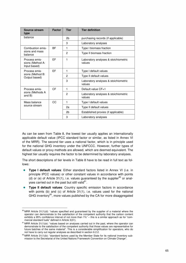
65
Source stream type
Factor Tier Tier definition
balance 2b purchasing records (if applicable)
3 Laboratory analyses
Combustion emis-sions and mass balance
BF 1 Type I biomass fraction
2 Type II biomass fraction
Process emis-sions (Method A: Input based)
EF 1 Laboratory analyses & stoichiometric values
Process emis-sions (Method B: Output based)
EF 1 Type I default values
2 Type II default values
3 Laboratory analyses & stoichiometric values
Process emis-sions (Methods A and B)
CF 1 Default value CF=1
2 Laboratory analyses & stoichiometric values
Mass balance source stream
CC 1 Type I default values
2a Type II default values
2b Established proxies (if applicable)
3 Laboratory analyses
As can be seen from Table 8, the lowest tier usually applies an internationally
applicable default value (IPCC standard factor or similar, as listed in Annex VI
of the MRR). The second tier uses a national factor, which is in principle used
for the national GHG inventory under the UNFCCC. However, further types of
default values or proxy methods are allowed, which are deemed equivalent. The
highest tier usually requires the factor to be determined by laboratory analyses.
The short descriptions of tier levels in Table 8 have to be read in full text as fol-
lows:
� Type I default values: Either standard factors listed in Annex VI (i.e. in
principle IPCC values) or other constant values in accordance with points
(d) or (e) of Article 31(1), i.e. values guaranteed by the supplier80
or anal-
yses carried out in the past but still valid81
.
� Type II default values: Country specific emission factors in accordance
with points (b) and (c) of Article 31(1), i.e. values used for the national
GHG inventory82
, more values published by the CA for more disaggregated
80
MRR Article 31(1)(d): “values specified and guaranteed by the supplier of a material where the operator can demonstrate to the satisfaction of the competent authority that the carbon content exhibits a 95% confidence interval of not more than 1%” – this is a similar approach as for “com-mercial standard fuels” defined in Article 3(31).
81 MRR Article 31(1)(e): “values based on analyses carried out in the past, where the operator can demonstrate to the satisfaction of the competent authority that those values are representative for future batches of the same material”. This is a considerable simplification for operators, who do not have to carry out regular analyses as described in section 6.2.2.
82 MRR Article 31(1)(b): “standard factors used by the Member State for its national inventory sub-mission to the Secretariat of the United Nations Framework Convention on Climate Change“.

66
fuel types, or other literature values which are agreed by the competent au-
thority83
.
� Established proxies: These are methods based on empirical correlations
as determined at least once per year in accordance with the requirements
applicable for laboratory analyses (see 6.2.2). However, these rather com-
plicated analyses are only carried out once per year, therefore this tier is
considered a lower level than full analyses. The proxy correlations may be
based on
� density measurement of specific oils or gases, including those com-
mon to the refinery or steel industry, or
� net calorific value for specific coal types.
� Purchasing records: Only in case of commercially traded fuels, the net
calorific value may be derived from the purchasing records provided by the
fuel supplier, provided it has been derived based on accepted national or
international standards.
� Laboratory analyses: In this case the requirements discussed in section
6.2.2 below are fully applicable.
� Type I biomass fraction84
: One of the following methods is applied, which
are considered equivalent:
� Use of a default value or an estimation method published by the
Commission in accordance with Article 39(2),
� Use a value determined in accordance with the second subparagraph
of Article 39(2), i.e.
� Assume the material fully fossil (BF=0), or
� Use an estimation method approved by the competent authority.
For fuels or materials originating from a production process with
defined and traceable input streams, the operator may base such
estimation on a mass balance of fossil and biomass carbon en-
tering and leaving the process.
� Apply Article 39(3) in case of natural gas grids, into which biogas is in-
jected: “where the guarantee of origin has been established in ac-
cordance with Articles 2(j) and 15 of Directive 2009/28/EC (Renewa-
ble Energy Sources Directive) for biogas injected into and subse-
quently removed from a gas network, the operator shall not use anal-
yses for the determination of the biomass fraction.” In this case that
guarantee of origin system has to be applied.
� Type II biomass fraction: The biomass fraction is determined in accord-
ance with Article 39(1), i.e. by laboratory analyses in accordance with the
requirements discussed in section 6.2.2. In that case the relevant standard
and the analytical methods therein to be used require the explicit approval
by the competent authority.
83
MRR Article 31(1)(c): “literature values agreed with the competent authority, including standard factors published by the competent authority, which are compatible with factors referred to in point (b), but they are representative of more disaggregated sources of fuel streams”.
84 Note that it is not discussed here how to determine whether the relevant sustainability criteria are met (if applicable). On biomass issues in general see guidance document No. 3 (see section 2.3).
67
6.2.2 Laboratory analyses
Where the M&R Regulation refers to determination “in accordance with Article
32 to 35”, this means that a parameter must be determined by (chemical) labor-
atory analyses. The MRR imposes relatively strict rules for such analyses, in
order to ensure a high quality level of the results. In particular, the following
points need consideration:
� The laboratory must demonstrate its competence. This is achieved by one
of the following approaches:
� An accreditation in accordance with EN ISO/IEC 17025, where the
analysis method required is within the accreditation scope; or
� Demonstrating that the criteria listed in Article 34(3) are satisfied. This
is considered reasonably equivalent to the requirements of EN
ISO/IEC 17025. Note that this approach is allowed only where use of
an accredited lab is shown to be technically not feasible or involving
unreasonable costs (� section 4.6).
� The way samples are taken from the material or fuel to be analysed is con-
sidered crucial for receiving representative results. Therefore the MRR puts
considerably more emphasis on this topic than the MRG 2007. Operators
have to develop sampling plans in the form of written procedures (� see
section 5.4) and get them approved by the competent authority. Note that
this applies also where the operator does not carry out the sampling him-
self, but treats it as an outsourced process.
� Analyses methods usually have to follow international or national stand-
ards85
.
Note that the above is usually related to the highest tiers for calculation factors.
Therefore these rather demanding requirements are rarely applicable to smaller
installations. In particular operators of installations with low emissions (� sec-
tion 4.4.2) may use “any laboratory that is technically competent and able to
generate technically valid results using the relevant analytical procedures, and
provides evidence for quality assurance measures as referred to in Article
34(3)”. In fact, the minimum requirements would be that the laboratory demon-
strates that it is technically competent and “capable of managing its personnel,
procedures, documents and tasks in a reliable manner”, and that it demon-
strates quality assurance measures for calibration and test results86
. However, it
is in the operator’s interest to receive reliable results from the laboratory. There-
fore operators should strive to comply with the requirements of Article 34 to the
highest degree feasible.
Furthermore it is important to note that the MRR in the activity specific require-
ments of Annex IV allow the use of “industry best practice guidelines” for some
85
For the use of standards, Article 32(1) defines the following hierarchy: “The operator shall ensure that any analyses, sampling, calibrations and validations for the determination of calculation fac-tors are carried out by applying methods based on corresponding EN standards. Where such standards are not available, the methods shall be based on suitable ISO standards or national standards. Where no applicable published standards exist, suitable draft standards, in-dustry best practice guidelines or other scientifically proven methodologies shall be used, limiting sampling and measurement bias.”
86 Examples for such measures are given in Article 34(3), point (j): regular participation in proficiency testing schemes, applying analytical methods to certified reference materials, or inter-comparison with an accredited laboratory.
small

68
lower tiers, where no default values are applicable. In such cases, where de-
spite approval to apply a lower tier methodology analyses are still required, it
may not be appropriate or possible to apply Articles 32 to 35 in full. However,
the competent authority should deem the following as minimum requirements:
� Where the use of an accredited laboratory is technically not feasible or
would lead to unreasonable costs, the operator may use any laboratory
that is technically competent and able to generate technically valid results
using the relevant analytical procedures, and provides evidence for quality
assurance measures as referred to in Article 34(3).
� The operator shall submit a sampling plan in accordance with Article 33.
� The operator shall determine the analysis of frequency in accordance with
Article 35.
More detailed guidance on topics related to laboratory analyses, sampling, fre-
quency of analyses, equivalence to accreditation etc. are given in guidance
document No. 5.
6.3 Calculation factors – specific requirements
In addition to the general approaches for determining calculation factors (default
values / analyses) as discussed in section 6.2 and the general overview given in
sections 4.3.1 and 4.3.2, some rules for each factor are laid down in the MRR.
These are discussed below.
6.3.1 Emission factor
Article 3(13) of the MRR defines: “‘emission factor’ means the average emission
rate of a greenhouse gas relative to the activity data of a source stream assum-
ing complete oxidation for combustion and complete conversion for all other
chemical reactions.” Furthermore Article 3(35) is important for materials contain-
ing biomass: “‘preliminary emission factor’ means the assumed total emission
factor of a mixed fuel or material based on the total carbon content composed of
biomass fraction and fossil fraction before multiplying it with the fossil fraction to
result in the emission factor”.
Important: According to section 2.1 of Annex II of the MRR, the tiers defined in
the MRR shall relate to the preliminary emission factor, where a biomass frac-
tion is determined for a mixed fuel or material. I.e. tiers are applicable always to
individual parameters.
As reflected by the definition, the emission factor is the stoichiometric factor
which converts the (fossil) carbon content of a material into the equivalent mass
of (fossil) CO2 assumed to be emitted. Adjustment for incomplete reactions is
handled via the oxidation or conversion factor. However, as mentioned in Article
37(1), sometimes national inventories don’t use oxidation or conversion factors
(i.e. those factors are set to 100%), but have the adjustment for incomplete re-
action included in the emission factor. Where such factors are used as default
values in accordance with Article 31(1)(b), operators should consult with the
competent authority, if in case of doubt.
69
For combustion emissions, the emission factor is expressed in relation to the
energy content (NCV) of the fuel rather than its mass or volume. However, un-
der certain conditions (where the use of an emission factor expressed as
t CO2/TJ incurs unreasonable costs or where at least equivalent accuracy of the
calculated emissions can be achieved) the competent authority may allow the
operator to use an emission factor expressed as t CO2/t fuel or t CO2/Nm3 (Arti-
cle 36(2)).
Where the applicable tier requires the emission factor to be determined by anal-
yses, the carbon content is to be analysed. Where a fuel or material contains
organic as well as inorganic carbon87
, usually the total carbon content is to be
determined. Note that inorganic carbon is always considered fossil.
For fuels, the NCV must also be determined (depending on the tier, this may
require another analysis of the same sample).
If the emission factor of a fuel expressed as t CO2/TJ is to be calculated from
the carbon content, the following equation is used:
NCVfCCEF /⋅=
(11)
If the emission factor of a material or fuel expressed as t CO2/t is to be calculat-
ed from the carbon content, the following equation is used:
fCCEF ⋅=
(12)
The variable names are explained in sections 4.3.1 and 4.3.2.
6.3.2 Net calorific value (NCV)
Because activity data of fuels is to be reported as energy content (� section
4.3.1), the NCV is an important parameter to be reported. This allows emission
reports to be compared with energy statistics and national GHG inventories un-
der the UNFCCC.
Note: Although the activity data of fuels is “NCV times the fuel quantity”, the tier
definitions for activity data refer to fuel quantity only, and the NCV is a separate
parameter (calculation factor), for which individual tiers are applicable.
However, under certain conditions, the NCV is not indispensable for the emis-
sion calculation. This is the case:
� where emission factors of fuels are expressed as t CO2/t fuel or t CO2/Nm3
(Article 36(2)88
);
� where fuels are used as process inputs; and
� fuels being part of a mass balance.
In those cases, the NCV may be determined using a lower tier than in other
cases (Article 26(5)).
87
E.g. paper contains organic carbon (cellulose fibres, resins etc) as well as inorganic carbon (car-bonate fillers).
88 This may be allowed by the competent authority if the use of an emission factor expressed as t CO2/TJ would incur unreasonable costs, or where at least equivalent accuracy can be achieved with this method.
70
6.3.3 Oxidation factor and conversion factors
These two factors are used to account for incomplete reaction. Thus, if they are
to be determined based on laboratory analyses, the factor would be determined
as follows (oxidation factor):
combash CCOF /1−= (13)
Where:
OF ....... Oxidation factor [dimensionless]
Cash ..... carbon contained in ash, soot and other non-oxidised forms of carbon
(excluding carbon monoxide, which is considered as molar equivalent of
CO2 emissions)
Ccomb ... (total) carbon combusted.
The two C variables are expressed as [tonnes C], i.e. quantity of material or fuel
times the concentration of carbon in it. Therefore not only the carbon content of
the ash has to be determined by analysis, but also the amount of ash must be
determined for the period for which the oxidation factor is determined.
Further points to be considered in line with Article 37:
� Unlike for other parameters, for all categories of installations and source
streams, tier 1 is the minimum applicable tier. This is equivalent to OF = 1
or CF = 1, i.e. reflects a conservative assumption in any event.
� Competent authorities are allowed to require an operator to use that tier 1.
As outlined in section 6.3.1, this may be required because in some cases
the effect of incomplete reaction has been included in the emission factor.
� Where several fuels are used in an installation and tier 3 (i.e. laboratory
analyses) is required, the operator may choose one of two options:
� Determination of one average oxidation for the whole combustion pro-
cess, to be applied to all involved source streams, or
� Attribution of the incomplete oxidation to one major source stream,
and use OF = 1 for the other source streams.
� Where biomass or mixed fuels are used, the operator must provide
evidence that an underestimation of emissions is avoided.
6.3.4 Carbon content in case of mass balances
Due to the close relation between emission factor in the standard methodology
and the carbon content in case of the mass balance, the items discussed under
section 6.3.1 (emission factor) apply as appropriate. In particular, analyses are
applicable in the same way, and default values given in Annex VI of the MRR
can be converted into default values for the carbon content by using the formu-
lae given in section 4.3.2.
71
6.3.5 Biomass fraction
A separate guidance document is provided89
for biomass related topics. These
topics cover:
� Criteria for zero-rating of biomass (i.e. whether it is allowed to set the
emission factor to zero). In particular practical approaches for applying the
sustainability criteria of the RES Directive90
are outlined.
� Determining the biomass fraction (Article 39);
� Simplifications, in particular regarding determining activity data (Article 38);
� A list of biomass materials.
6.4 PFC emissions
Section 8 of Annex IV of the M&R Regulation describes the determination of
PFC (Perfluorocarbon) emissions. PFC emissions are currently only covered by
the ETS for the activity “production of primary aluminium”. The gases to be
monitored are CF4 and C2F6. Emissions from anode effects as well as fugitive
emissions are to be included.
The MRR specifies that “the most recent version of the guidance mentioned un-
der Tier 3 of section 4.4.2.4 of the 2006 IPCC Guidelines shall be used.” That
guidance is the “Aluminium sector greenhouse gas protocol” published by the
International Aluminium Institute (IAI)91
. This uses a calculation based approach
which significantly deviates from the calculation based approach outlined in sec-
tion 4.3.1. Two different methods are allowed by the MRR: The “slope method”
and the “overvoltage method”. Which method is to be applied depends on the
installation’s process control equipment.
While the MRR describes the principle requirements and calculation formulae,
other details on the applicable methods should be taken from the guidance
mentioned above. Note that the IAI guidance is not applicable for CO2 emis-
sions from primary aluminium production and from anode production. Instead
the MRR’s usual calculation methods are to be used.
For calculating CO2(e) emissions from CF4 and C2F6 emissions, the operator
shall use the following formula:
624)()(
624 FCCF GWPFCEmGWPCFEmEm ⋅+⋅= (14)
Where
Em .............. emissions expressed as t CO2(e)
Em(CF4) ...... emissions of CF4 in tonnes
89
Guidance document No. 3. For reference see section 2.3. 90
RES means Renewable Energy Sources. The RES Directive is “Directive 2009/28/EC of the Eu-ropean Parliament and of the Council of 23 April 2009 on the promotion of the use of energy from renewable sources and amending and subsequently repealing Directives 2001/77/EC and 2003/30/EC”, downloadable under: http://eur-lex.europa.eu/LexUriServ/LexUriServ.do?uri=OJ:L:2009:140:0016:0062:EN:PDF
91 Download at http://www.world-aluminium.org/media/filer/2012/06/12/fl0000234.pdf

72
Em(C2F6) ..... emissions of C2F6 in tonnes
GWP ........... Global warming potential as listed in MRR Annex VI section 3
Table 6.
73
7 SIMPLIFIED APPROACHES
7.1 Installations with low emissions
For the definition of installations with low emissions, see section 4.4.2. For
those installations several simplifications are found in Article 47 of the MRR.
These are:
� The installation may use a simplified monitoring plan (where a Member
State has provided an appropriate template), see section 7.2.
� The operator may apply as a minimum tier 1 for activity data and calcula-
tion factors for all source streams, unless higher accuracy is achievable
without additional effort for the operator (i.e. no justifications regarding un-
reasonable costs are required).
� The operator is not required to submit the supporting documents men-
tioned in Article 12(1) when submitting a monitoring plan for approval, i.e.
there is no requirement for submitting
� evidence that the required tiers are met (uncertainty assessment, see
section 5.3), and
� a risk assessment as part of the control system.
� The operator is exempted from reporting on improvements reacting on find-
ings by the verifier.
� The operator may determine the amount of fuel or material by using avail-
able and documented purchasing records and estimated stock changes,
without providing an uncertainty assessment.
� He is also exempted from including the uncertainty of determined stocks at
the beginning and end of the year in the uncertainty assessment.
� If the operator uses analyses by a non-accredited laboratory, simplified ev-
idence regarding the competence of the laboratory92
is needed.
All other requirements for installations are to be respected. However, because
an installation with low emissions may apply lower tiers, the overall monitoring
requirements are usually relatively easy to meet.
7.2 Other “simple” installations
The M&R Regulation aims to avoid unreasonable or disproportionate costs for
installations wherever possible. The concept of “installations with low emis-
sions” as introduced already by the MRG 2007 has been found useful, but not
enough, as there are many installations participating in the EU ETS which are
rather simple to monitor, but which could not make use of some of the simplifi-
cations offered to installations with low emissions.
Before we discuss further elements of the MRR, we must ask how a monitoring
plan can be simplified in general, i.e. how can the administrative burden for op-
92
The operator may use “any laboratory that is technically competent and able to generate techni-cally valid results using the relevant analytical procedures, and provides evidence for quality as-surance measures as referred to in Article 34(3)”. See section 6.2.2 for further details.
small

74
erators (of “simple” installations) be reduced? In principle, there are three areas
which have to be covered in the monitoring plan (assuming that “simple” instal-
lations always use a calculation based methodology for monitoring):
� Monitoring of activity data,
� Determination of calculation factors, and
� Organisational issues, including data flow and control procedures.
When analysing the MRR’s possibilities for simplification, it turns out that its re-
quirements are largely proportionate anyway. I.e. if an installation is really sim-
ple, the monitoring is also simple to perform. For monitoring of activity data the
most obvious simplification is the use of invoices. For calculation factors, only
the highest tiers require more effort due to the laboratory analyses to be per-
formed, while smaller emitters are usually entitled to use default values. The on-
ly remaining area for simplification are the “organisational” issues (of which
many require written procedures). This is exactly where Article 13 of the MRR
comes in.
The M&R Regulation provides a flexible approach to allow simplifications where
deemed appropriate by the competent authority. Article 13(1) of the MRR gives
Member States the possibility to allow operators to use standardised or simpli-
fied monitoring plans, for which the Member States may publish templates
based on the templates and guidelines published by the Commission. That Arti-
cle mentions in particular the possibility that such templates include (standard-
ised) descriptions of data flow and control procedures (� section 5.5).
Dedicated templates may solve two issues: Firstly, the minimum content of
monitoring plans, found in Annex I of the MRR as well as in the electronic tem-
plates for monitoring plans provided by the Commission, aims at avoiding gaps
in the monitoring plans of complex installations. Fully responding to these needs
may result in unnecessary burden for operators of small or simple installations.
Secondly, there may be elements of monitoring plans which apply to many in-
stallations in a similar way. It would be a considerable simplification for opera-
tors if there were standardised texts available which they may use where ap-
propriate, rather than developing everything themselves. An additional efficien-
cy improvement, in the process of approving monitoring plans, results where the
competent authorities themselves would disseminate information on text blocks
which are deemed appropriate in standard situations.
7.2.1 Practical approach to simplifications
Bearing in mind the nature and functioning of the monitoring plan templates
provided by the Commission, it seems most practical for Member States who
want to make use of Article 13 to provide modified versions of the Commission’s
original monitoring plan template. Those modified templates can be adapted to
the needs of simple installations in particular by two elements:
� Hiding sheets or sections of the template93
which are not relevant;
93
Note that the original template does not hide full sections due to transparency considerations. Sections which are not relevant due to other data inputs are made automatically grey by the origi-nal template, but are not hidden.
75
� Inserting standard text blocks in the template, for example for standard da-
ta sources (national GHG inventory etc) or default values, simple data flow
and control procedures.
Such approach would also support those operators which can use only parts of
the simplified or standardised monitoring plan templates.
Note that the simplifications made in the templates must be appropriate for the
types of installations for which these templates are developed.
7.2.2 Determining the scope for simplified approaches
The central tool for determining the appropriateness of simplifications is the risk
assessment94
. Competent authorities may allow any use of a standardised and
simplified approach in the monitoring plan only where this does not lead to an
undue risk of misstatements in the emission report. Because each installation is
different, it does not seem appropriate to define one single way of broad simpli-
fication to a wide range of installations. Instead the MRR offers flexibility to
competent authorities, but requires that any simplification be justifiable based
on a simplified risk assessment.
It is acknowledged that a detailed risk assessment may be a disproportionate
effort for a competent authority. Therefore this guidance provides some indica-
tors based on which competent authorities may decide whether simplifications
can be allowed. It is proposed to classify installations into one of the three fol-
lowing groups:
1. Installation types which are considered too complex for allowing simplifica-
tions under Article 13 (� indicators given in section 7.2.2.1),
2. Installations which are considered eligible for simplified or standardised
monitoring plans under Article 13 (� section 7.2.2.2), and
3. Installations where an assessment of the individual situation is required.
In the third case, competent authorities are encouraged to make use of the se-
cond sub-paragraph of Article 13(2), i.e. that it should be the operator who per-
forms a risk assessment for his installation. In this particular case it may be
most appropriate to apply only some of the simplifications offered in standard-
ised monitoring plan templates.
7.2.2.1 Installations with potentially high risks
The following types of installations are considered too complex for allowing
simplified MPs:
� Installations applying measurement based approaches (CEMS),
� Installations carrying out activities where PFC or N2O are included in An-
nex I of the EU ETS Directive,
94
Article 13(2): “Before the approval of any simplified monitoring plan referred to in paragraph 1, the competent authority shall carry out a simplified risk assessment as to whether the proposed con-trol activities and procedures for control activities are commensurate with the inherent risks and control risks identified, and justify the use of such a simplified monitoring plan. Member States may require the operator or aircraft operator to carry out the risk assessment pur-suant to the previous sub-paragraph itself, where appropriate.

76
� Installations for capture, transport and geological storage of CO2, as in-
cluded in Annex I of the EU ETS Directive,
� Installations applying a fall-back methodology in accordance with Article 22
of the MRR,
� Category C installations which apply other source streams than commer-
cial standard fuels,
� Category B or C installations which have at least one major source stream
for which instruments are used which are not subject to national legal met-
rological control,
� Installations which have to use laboratory analyses in accordance with Ar-
ticles 33 to 35,
� Installations which have more than three major source streams to monitor,
or which apply several different monitoring methodologies (e.g. batch me-
tering as well as some continual measurements for activity data, several
different sampling plans,…)
7.2.2.2 Installations eligible for simplified monitoring plans
The following types of installations are considered generally eligible for allowing
simplified MPs:
� Installations of category A and B which have only natural gas as source
stream,
� installations which use only commercial standard fuels without process
emissions,
� installations which
� can use exclusively invoices for monitoring activity data,
� use exclusively default values for calculation factors, and
� which use a limited number95
of source streams with fossil carbon;
� Installations with low emissions, if
� only minor and de-minims source streams are not monitored using in-
voices and default values,
� the installation does not use CEMS or fall-back approaches, and
� the installation does not carry out PFC or N2O emitting activities or
capture, transport or geological storage of CO2.
� Installations emitting fossil CO2 only from minor and de-minimis source
streams.
This list includes also all installations which comply with the above criteria, but
have to monitor one or more biomass source streams in addition. In other
words, biomass source streams do not affect the eligibility for simplified ap-
proaches, as the following example shows.
95
As guidance, the CA should perform an individual assessment where the number of source streams exceeds 10.

77
Assuming an installation of category A or B which has only natural gas as
source stream, and uses in addition various types of solid biomass. This could
be e.g. a biomass plant for district heating, which uses natural gas for covering
peak load periods.
If ignoring the biomass, it complies with the first criterion presented above. It is
therefore also eligible for simplified approaches as a whole.

78
8 CEMS
8.1 General requirements
In addition to what has been outlined in section 4.3.3 about measurement
based methodologies, further points are to be taken into account:
� In contrast to the MRG 2007, CEMS are now put on equal footing with cal-
culation based approaches, i.e. it is not necessary any more to demon-
strate to the CA that using a CEMS achieves greater accuracy than the
calculation approach using the most accurate tier approach. However, min-
imum tier (� see section 5.2) requirements have been defined implying
uncertainty levels comparable to those of calculation approaches are appli-
cable. Thus, the operator must demonstrate to the CA that those tiers can
be met with the CEMS proposed. Table 9 gives an overview on defined ti-
ers for measurement based approaches.
� The measurement based emissions must be corroborated using a calcula-
tion based approach. However, no specific tiers are required for this calcu-
lation. Thus, this is a considerable simplification compared to the MRG
2007, where at least lower tiers had to be applied.
Due to the non-stoichiometric nature of N2O emissions from nitric acid pro-
duction, no corroborating calculation is required for those emissions.
� Carbon monoxide (CO) emitted to the atmosphere shall be treated as the
molar equivalent amount of CO2 (Article 43(1)).
� Concentration measurements may be difficult in gas streams of very high
CO2 concentrations. This is in particular important for measurement of CO2
transferred between installations for the capture, pipeline systems for the
transport and installations for geological storage of CO2. In such cases CO2
concentrations may be determined indirectly, by determining the concen-
tration of all other constituents of the gas and subtracting them from the to-
tal (Equation 3 in Annex VIII of the MRR).
� Flue gas flow may be determined either by direct measurement, or by a
mass balance96
using only parameters which are easier to measure, name-
ly input material flows, input airflow and concentration of O2 and other gas-
es which need to be measured also for other purposes.
� The operator must ensure that the measurement equipment is suitable for
the environment in which it is to be used, and regularly maintained and cal-
ibrated. Nevertheless the operator must be aware that equipment may fail
once in a while. Therefore Article 45 outlines how data from missing hours
are to be conservatively replaced. The operator has to make provisions for
such data substitution when developing the monitoring plan97
.
96
Article 43(5) allows the use of “a suitable mass balance, taking into account all significant parame-ters on the input side, including for CO2 emissions at least input material loads, input airflow and process efficiency, as well as on the output side including at least the product output, the O2, SO2 and NOx concentration”.
97 In accordance with point (4)(a)(ii) of section 1 of Annex I of the MRR, the monitoring plan must contain: “the method for determining whether valid hours or shorter reference periods for each pa-rameter can be calculated, and for substitution of missing data in accordance with Article 45”.
79
� Operators must apply EN 14181 (“Stationary source emissions – Quality
assurance of automated measuring systems”) for quality assurance. This
standard requires several activities:
� QAL 1: Testing whether the CEMS is meeting the specified re-
quirements. For this purpose EN ISO 14956 (“Air quality. Eval-
uation of the suitability of a measurement procedure by com-
parison with a required uncertainty measurement”) is to be
used.
� QAL 2: Calibration and validation of the CEM;
� QAL 3: Ongoing quality assurance during operation;
� AST: Annual surveillance test
According to the standard, QAL 2 and AST are to be performed by accred-
ited laboratories, QAL 3 is performed by the operator. Competence of the
personnel carrying out the tests must be ensured.
This standard does not cover quality assurance of any data collection or
processing system (i.e. IT systems). For those the operator has to ensure
appropriate quality assurance by separate means.
� Another standard to be applied is EN 15259 (“Air quality – Measurement of
stationary source emissions – Requirements for measurement sections
and sites and for the measurement objective, plan and report”)
� All other methods applied in the context of the measurement based ap-
proach should be based also on EN standards. Where such standards are
not available, the methods shall be based on suitable ISO standards,
standards published by the Commission or national standards. Where no
applicable published standards exist, suitable draft standards, industry best
practice guidelines or other scientifically proven methodologies shall be
used, limiting sampling and measurement bias.
The operator shall consider all relevant aspects of the continuous meas-
urement system, including the location of the equipment, calibration,
measurement, quality assurance and quality control.
� The operator shall ensure that laboratories carrying out measurements,
calibrations and relevant equipment assessments for continuous emission
measurement systems (CEMS) shall be accredited in accordance with EN
ISO/IEC 17025 for the relevant analytical methods or calibration activities.
Where the laboratory does not have such accreditation, the operator shall
ensure that equivalent requirements of Article 34(2) and (3) are met.
Table 9: Tiers defined for CEMS (see section 1 of Annex VIII of the MRR), expressed
using the maximum permissible uncertainties for the annual average hourly
emissions.
Tier 1 Tier 2 Tier 3 Tier 4
CO2 emission sources ± 10% ± 7.5% ± 5% ± 2.5%
N2O emission sources ± 10% ± 7.5% ± 5% N.A.
CO2 transfer ± 10% ± 7.5% ± 5% ± 2.5%
80
8.2 N2O emissions
Section 16 of Annex IV of the MRR deals with determining N2O emissions from
certain chemical production processes, which are covered by Annex I of the EU
ETS Directive (production of nitric acid, adipic acid, glyoxal and glyoxylic acid),
or which may be unilaterally included pursuant to Article 24 of the Directive
(production of caprolactam). N2O emitted from the activity “combustion of fuel”
is not covered. N2O emissions usually have to be determined using a meas-
urement based approach.
In addition to the points mentioned under sections 4.3.3 and 8.1, the following
specific points should be noted:
� In subsection B.3 of section 16 of Annex IV specific requirements for de-
termining the flue gas flow are given. Where needed, the oxygen concen-
tration must be measured in accordance with subsection B.4.
� Subsection B.5 specifies requirements for calculation of N2O emissions in
case of specific periods of unabated N2O emissions (e.g. when the abate-
ment system fails) and where measurement is technically not feasible.
For calculating CO2(e) emissions from N2O emissions, the operator shall use the
following formula:
ONGWPONEmEm2
)(2
⋅= (15)
Where
Em .............. emissions expressed as t CO2(e)
Em(N2O) ..... emissions of N2O in tonnes
GWPN2O ...... Global warming potential of N2O as listed in MRR Annex VI
section 3 Table 6.
8.3 Transferred / inherent CO2 and CCS
8.3.1 Transferred CO2 and CCS
The MRR has brought a considerable change compared to the MRG 2007
where “transferred CO2” is concerned.
Under the new rules, CO2 being not emitted, but transferred out of an installa-
tion may be subtracted from that installation’s emissions only if the receiving in-
stallation is one of the following (Article 49(1)):
� a capture installation for the purpose of transport and long-term geological
storage in a storage site permitted under Directive 2009/31/EC;
� a transport network with the purpose of long-term geological storage in a
storage site permitted under Directive 2009/31/EC;
� a storage site permitted under Directive 2009/31/EC for the purpose of
long-term geological storage.

81
In all other cases, the CO2 transferred out of the installation counts as emission
of the originating installation.
In order to make the calculation consistent in the case of a “CCS chain” (i.e.
several installations together performing the capture, transport and geological
storage of CO2), the receiving installation has to add that CO2 to its emissions
(see sections 21 to 23 of Annex IV of the MRR), before it may again subtract
the amount transferred to the next installation or to the storage site. Thus, CCS
installations are monitored using a form of mass balance approach, where
some of the CO2 entering or leaving the installation (i.e. at the transfer points) is
monitored using continuous measurement systems.
For these continuous measurement systems (CMS) the rules specified for
CEMS (�sections 4.3.3 and 8.1) apply mutatis mutandis (the word “emissions”
has to be omitted from CEMS). In particular the provision of “indirect” CO2
measurement98
is applicable. The highest tier (tier 4) has to be used, unless un-
reasonable costs or technical infeasibility are demonstrated. As a special provi-
sion, it is important to clearly identify the transferring and receiving installations
in annual emissions report, using the unique identifiers which are also used in
the ETS registry system.
For monitoring at the interface between installations, the operators may choose
whether the measurement is carried out by the transferring or receiving installa-
tion (Article 48(3)). Where both carry out measurements and where the results
deviate, the arithmetic mean shall be used. If the deviation is higher than the
uncertainty approved in the MP, a value with conservative adjustment is to be
reported by the operators, which needs the approval by the competent authori-
ty.
8.3.2 Inherent CO2
While “transferred CO2” in the MRR means “more or less pure CO2” (the CCS
Directive99
requires the CO2 stream to “consist overwhelmingly” of CO2), the
term “inherent CO2” in the MRR (article 48) refers to CO2 which results from an
Annex I activity and is contained in a gas which is considered a fuel, such as
waste gases from a blast furnace or from some parts of mineral oil refineries.
In order to ensure a consistent reporting of both receiving and transmitting in-
stallation, the following approaches are applicable:
� Where an installation uses a fuel which contains inherent CO2, the emis-
sion factor (or in case of mass balances, the carbon content) takes into ac-
count the inherent CO2 (i.e. the CO2 forms a part of the source stream, and
the inherent CO2 counts as emitted by the installation which indeed emits
the CO2).
� The installation which transfers the CO2 to the other installation, subtracts
the CO2 from its emissions. Usually this is done using a mass balance. The
inherent CO2 is simply treated in the same way as any other carbon in that
outgoing source stream.
98
I.e. determining the concentration of all other constituents of the gas and subtracting them from the total (Equation 3 in Annex VIII of the MRR).
99 Directive 2009/31/EC

82
� An exception is applicable where the inherent CO2 is transferred to a non-
ETS installation: In this case the inherent CO2 has to be counted as emis-
sion.
Regarding monitoring the point of transfer, the same approach as for trans-
ferred CO2 is applicable, i.e. operators may choose whether the measurement
is carried out by the transferring or receiving installation (Article 48(3), see sec-
tion 8.3.1 above).
83
9 ANNEX
9.1 Acronyms
EU ETS ....... EU Emission Trading Scheme
MRV ............ Monitoring, Reporting and Verification
MRG 2007 .. Monitoring and Reporting Guidelines
MRR ............ Monitoring and Reporting Regulation (M&R Regulation)
AVR ............ Accreditation and Verification Regulation (A&V Regulation)
MP .............. Monitoring Plan
Permit ......... GHG emissions permit
CIMs .......... Community-wide fully harmonised Implementing Measures (i.e. al-
location rules based on Article 10a of the EU ETS Directive)
CA .............. Competent Authority
ETSG .......... ETS Support Group (a group of ETS experts under the umbrella of
the IMPEL network, who have developed important guidance notes
for the application of the MRG 2007)
IMPEL ......... European Union Network for the Implementation and Enforcement
of Environmental Law (http://impel.eu)
AER ............ Annual Emissions Report
CEMS ......... Continuous Emission Measurement System
MPE ............ Maximum Permissible Error (term usually used in national legal
metrological control)
MS .............. Member State(s)
CCS ............ Carbon Capture and [geological] Storage
9.2 Legislative texts
EU ETS Directive: Directive 2003/87/EC of the European Parliament and of the
Council of 13 October 2003 establishing a scheme for greenhouse gas emis-
sion allowance trading within the Community and amending Council Directive
96/61/EC, most recently amended by Directive 2009/29/EC. Download consoli-
dated version:
http://eur-lex.europa.eu/LexUriServ/LexUriServ.do?uri=CONSLEG:2003L0087:20090625:EN:PDF
M&R Regulation: Commission Regulation (EU) No. 601/2012 of 21 June 2012
on the monitoring and reporting of greenhouse gas emissions pursuant to Di-
rective 2003/87/EC of the European Parliament and of the Council.
http://eur-lex.europa.eu/LexUriServ/LexUriServ.do?uri=OJ:L:2012:181:0030:0104:EN:PDF
A&V Regulation: Commission Regulation (EU) No. 600/2012 of 21 June 2012
on the verification of greenhouse gas emission reports and tonne-kilometre re-

84
ports and the accreditation of verifiers pursuant to Directive 2003/87/EC of the
European Parliament and of the Council.
http://eur-lex.europa.eu/LexUriServ/LexUriServ.do?uri=OJ:L:2012:181:0001:0029:EN:PDF
MRG 2007: Commission Decision 2007/589/EC of 18 July 2007 establishing
guidelines for the monitoring and reporting of greenhouse gas emissions pursu-
ant to Directive 2003/87/EC of the European Parliament and of the Council. The
download of the consolidated version contains all amendments: MRG for N2O
emitting activities, aviation activities; capture, transport in pipelines and geologi-
cal storage of CO2, and for the activities and greenhouse gases only included
from 2013 onwards. Download:
http://eur-lex.europa.eu/LexUriServ/LexUriServ.do?uri=CONSLEG:2007D0589:20110921:EN:PDF
RES Directive: Directive 2009/28/EC of the European Parliament and of the
Council of 23 April 2009 on the promotion of the use of energy from renewable
sources and amending and subsequently repealing Directives 2001/77/EC and
2003/30/EC. Download:
http://eur-lex.europa.eu/LexUriServ/LexUriServ.do?uri=OJ:L:2009:140:0016:0062:EN:PDF